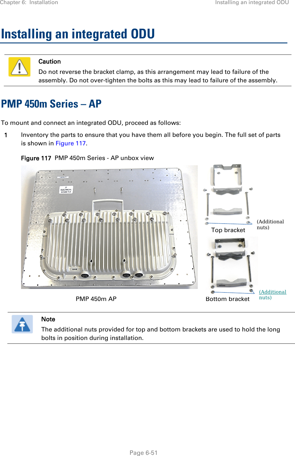
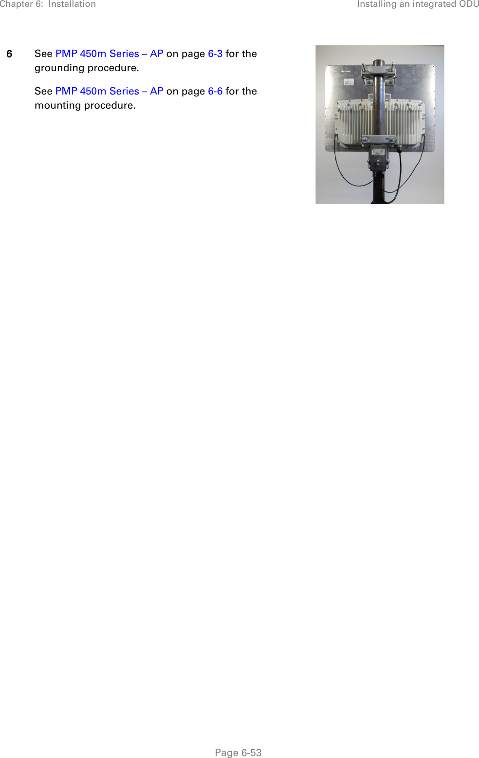
Cambium Networks 50450I Fixed Outdoor Point to Multipoint Transceiver User Manual 450 Platform User Guide
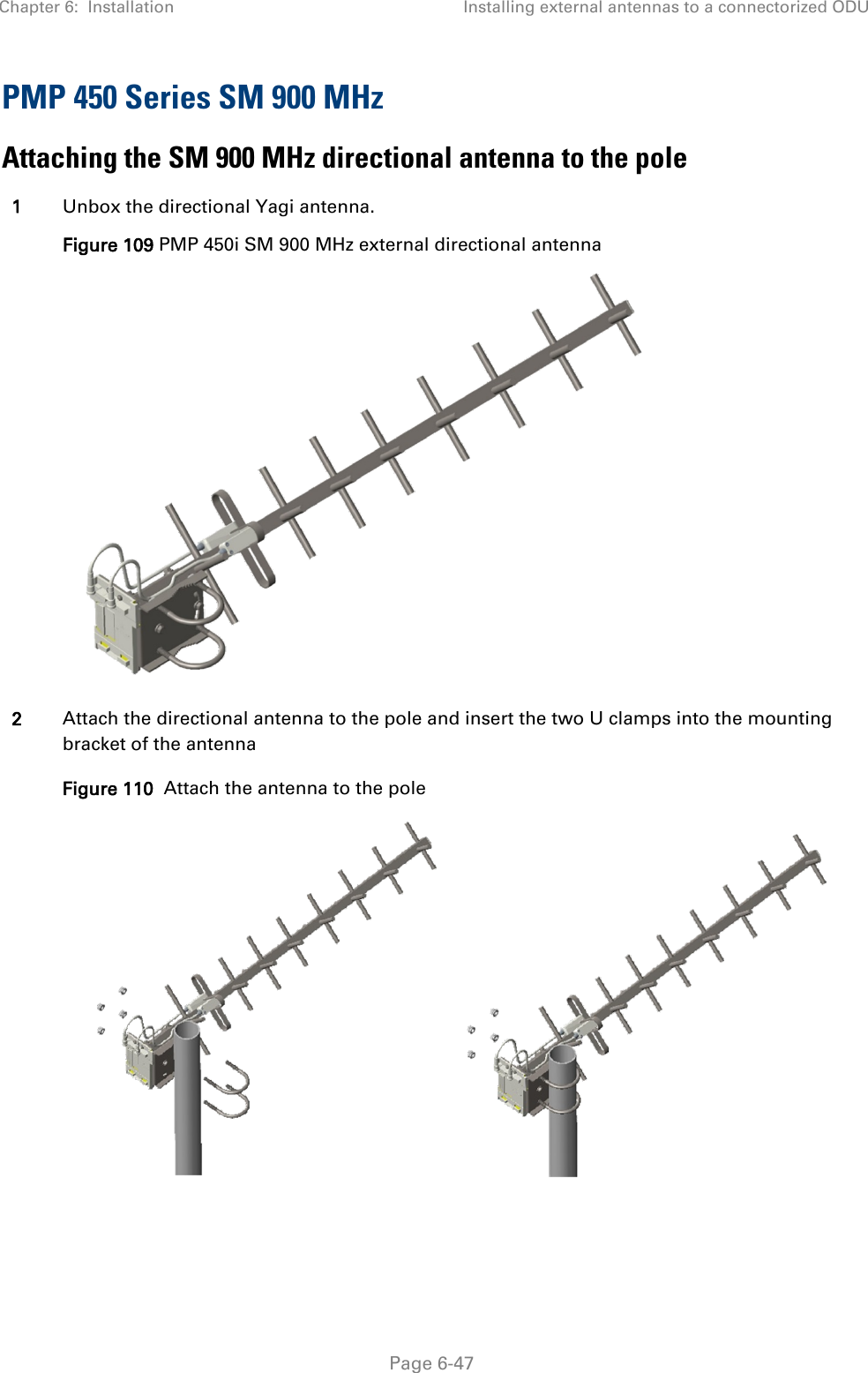
Cambium Networks Limited Fixed Outdoor Point to Multipoint Transceiver 450 Platform User Guide
Contents
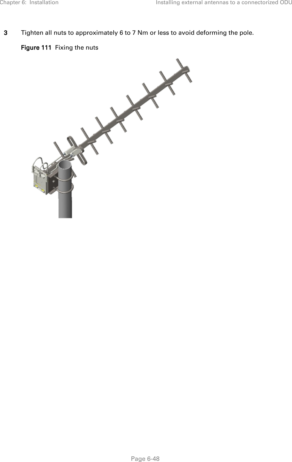
- 1. Installation Guide
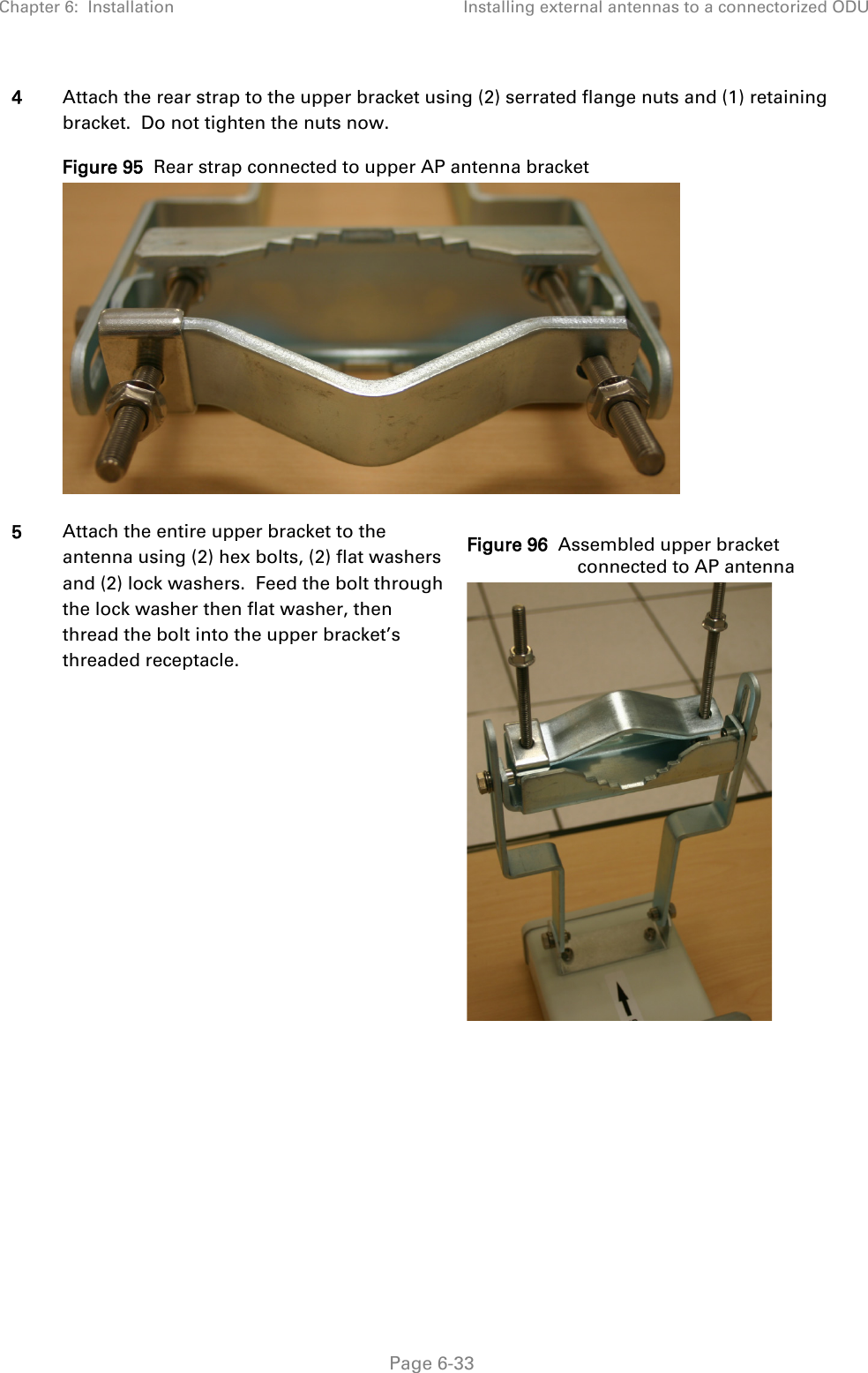
- 2. User Guide Part 1
- 3. User Guide Part 2
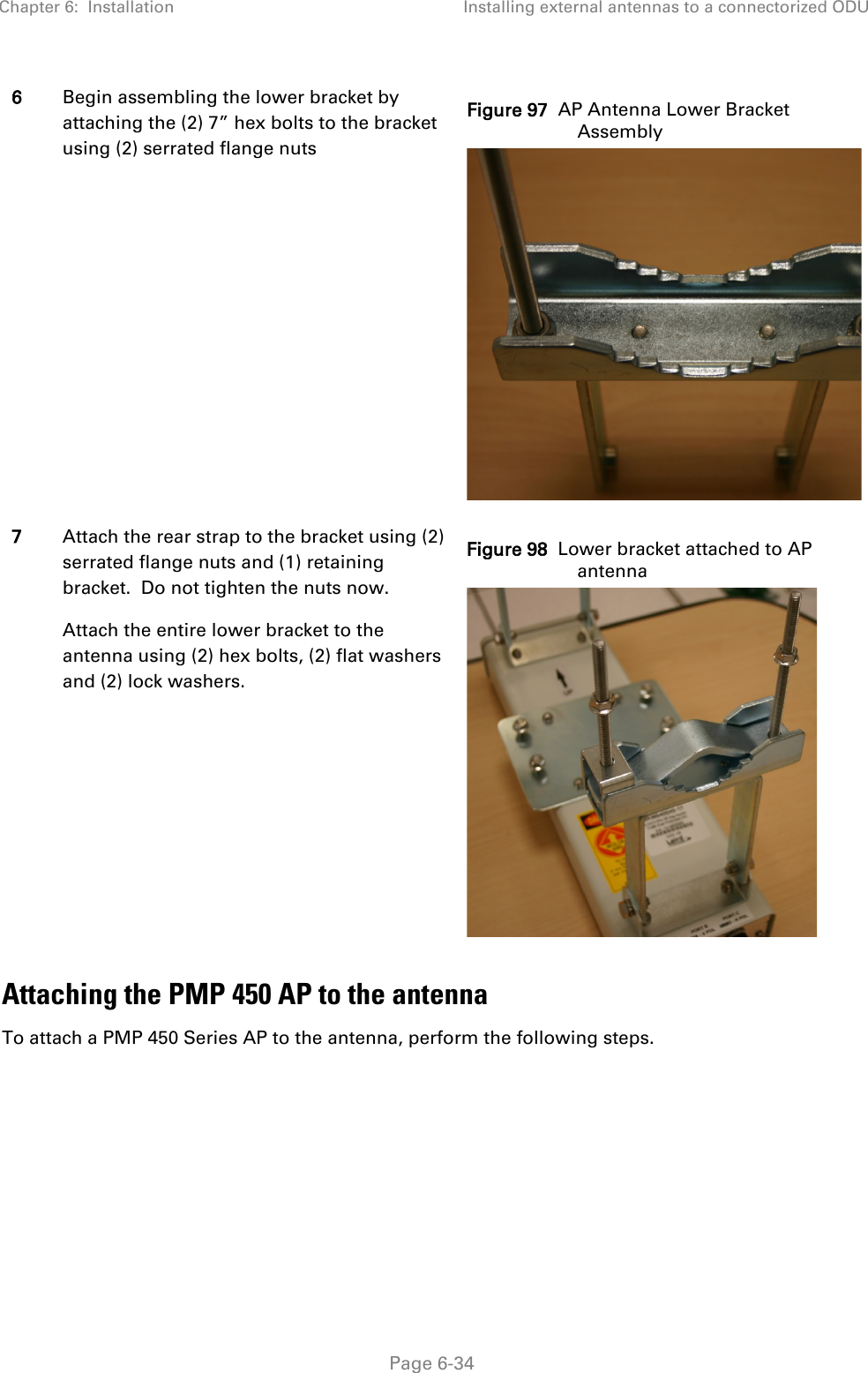
- 4. User Guide Part 3
- 5. User Guide Part 4
- 6. User Guide Part 5
- 7. User Guide Part 6
- 8. User Guide Part 7
- 9. Exhibit D Users Manual per 2 1033 b3
- 10. User Manual - Part 1
- 11. User Manual - Part 2
- 12. User Manual - Part 3
- 13. User Manual - Part 4
- 14. Users Manual - Part 5
- 15. Users Manual - Part 6
- 16. User Manual
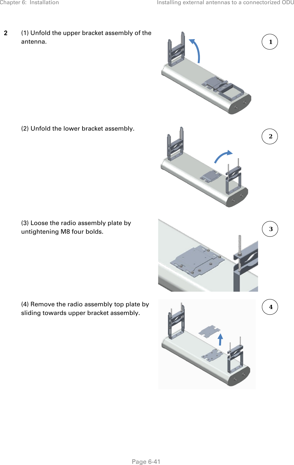
User Manual - Part 3