Cambium Networks 50450I Fixed Outdoor Point to Multipoint Transceiver User Manual 450 Platform User Guide
Cambium Networks Limited Fixed Outdoor Point to Multipoint Transceiver 450 Platform User Guide
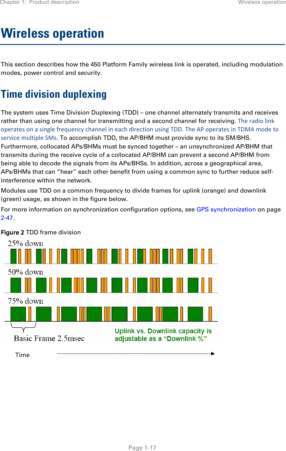
Contents
- 1. Installation Guide
- 2. User Guide Part 1
- 3. User Guide Part 2
- 4. User Guide Part 3
- 5. User Guide Part 4
- 6. User Guide Part 5
- 7. User Guide Part 6
- 8. User Guide Part 7
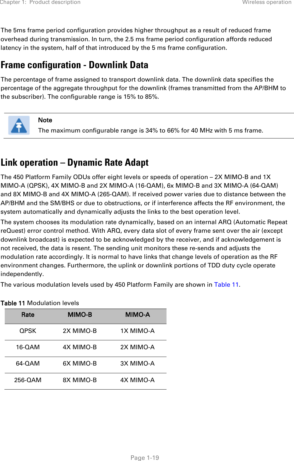
- 9. Exhibit D Users Manual per 2 1033 b3
- 10. User Manual - Part 1
- 11. User Manual - Part 2
- 12. User Manual - Part 3
- 13. User Manual - Part 4
- 14. Users Manual - Part 5
- 15. Users Manual - Part 6
- 16. User Manual
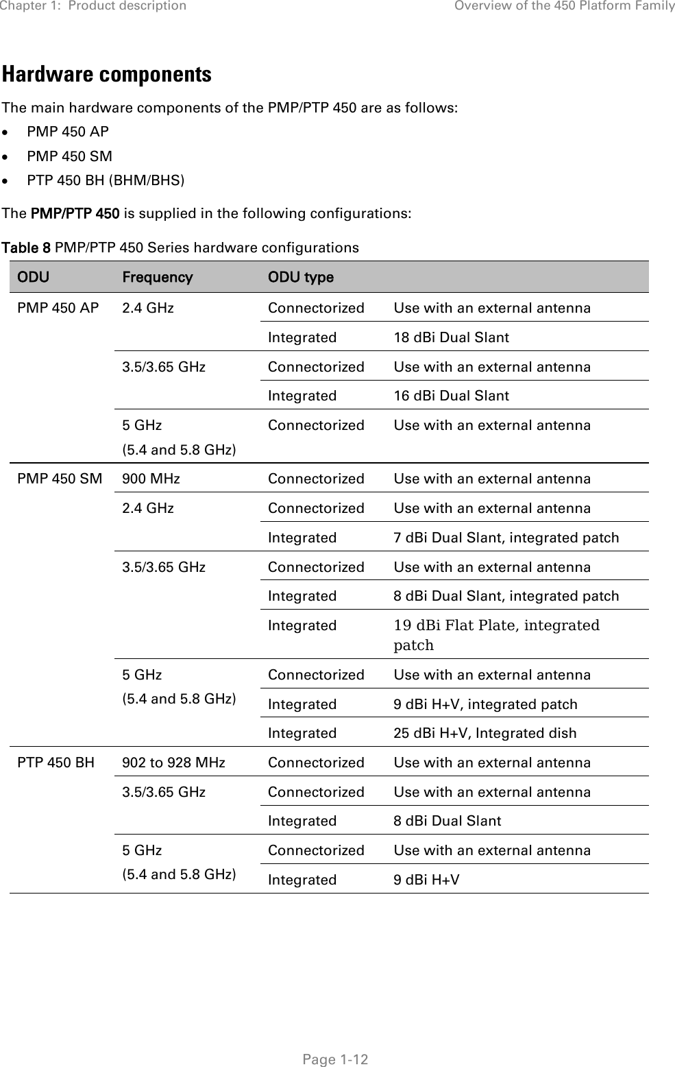
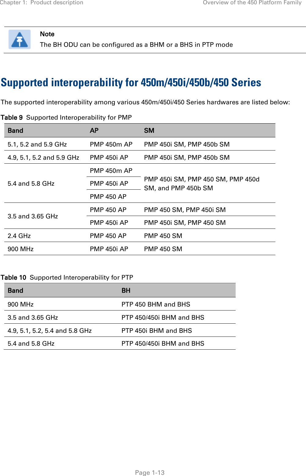
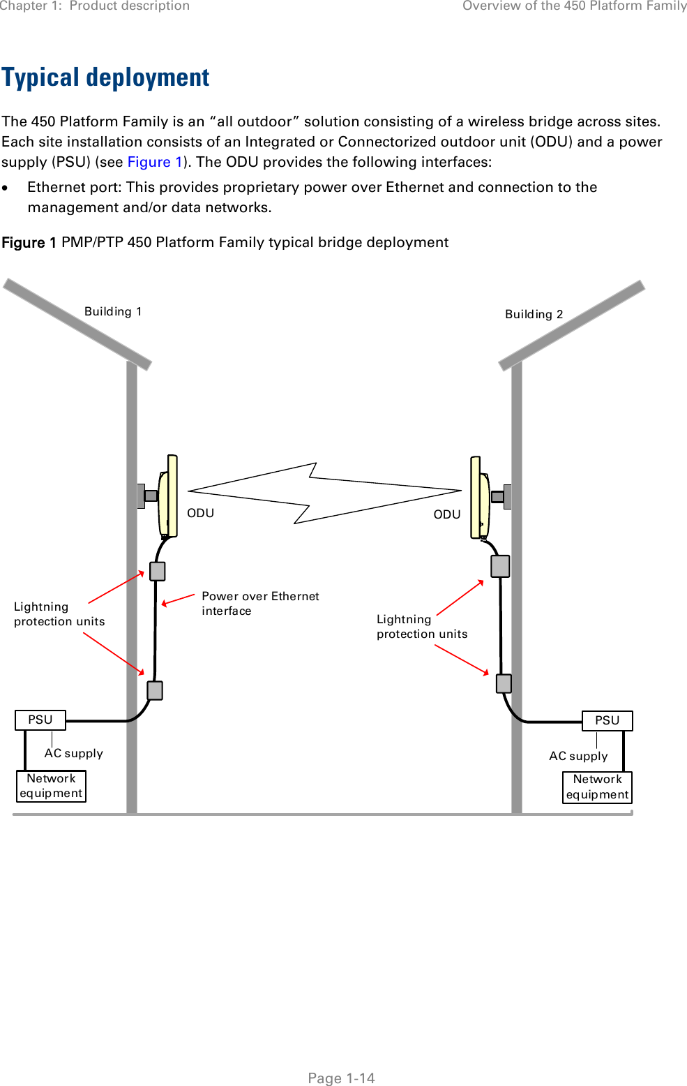
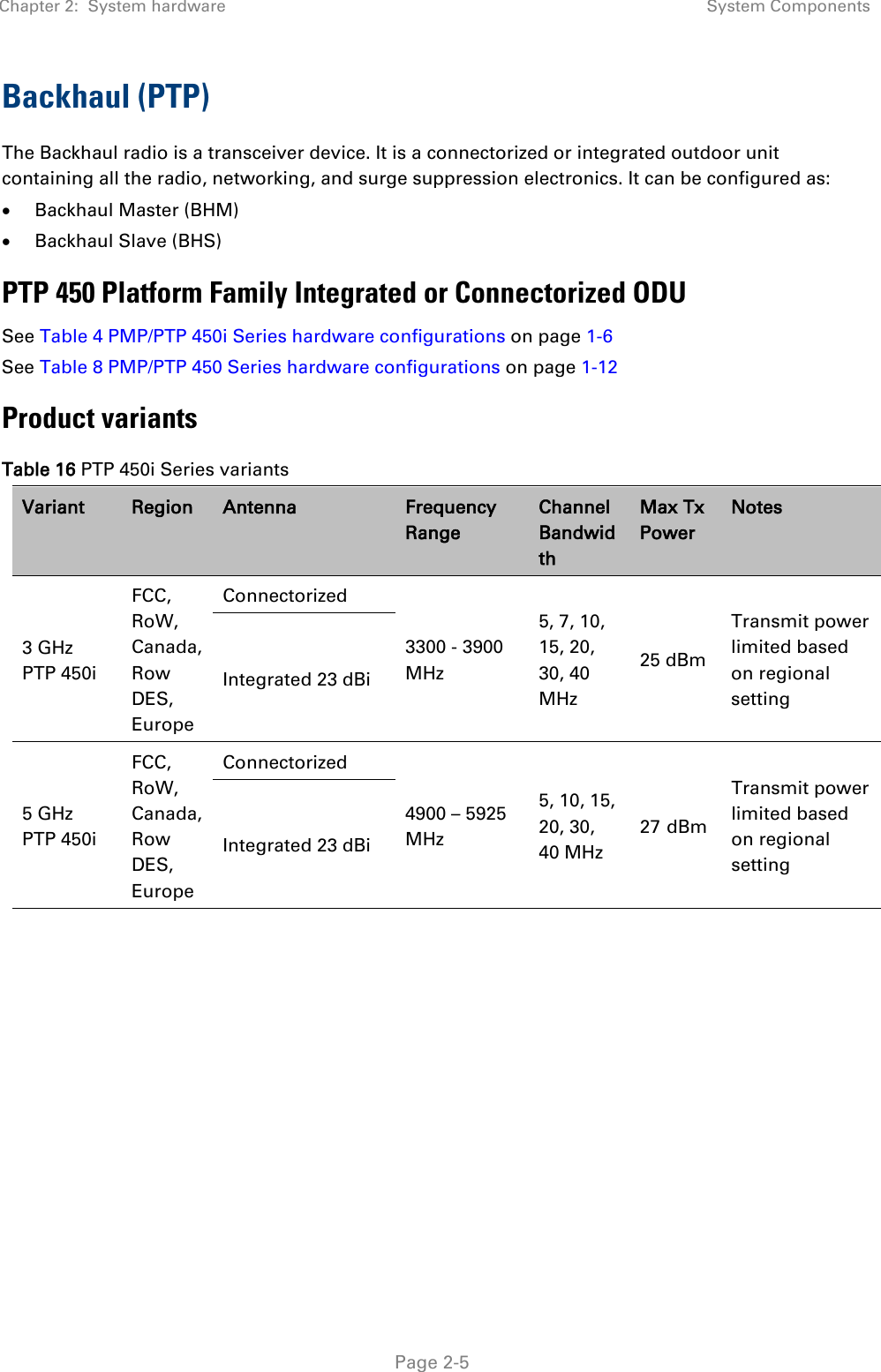
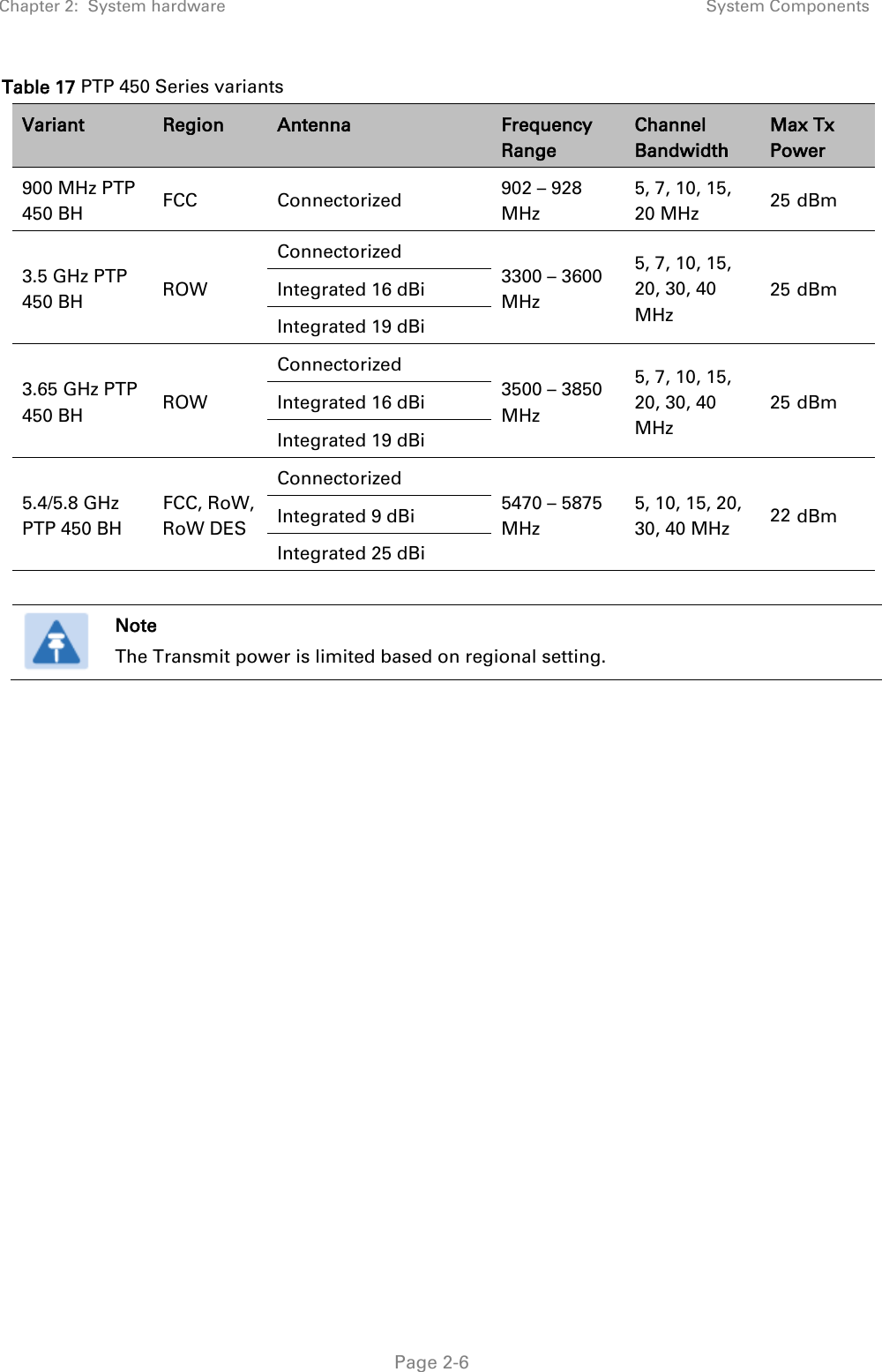
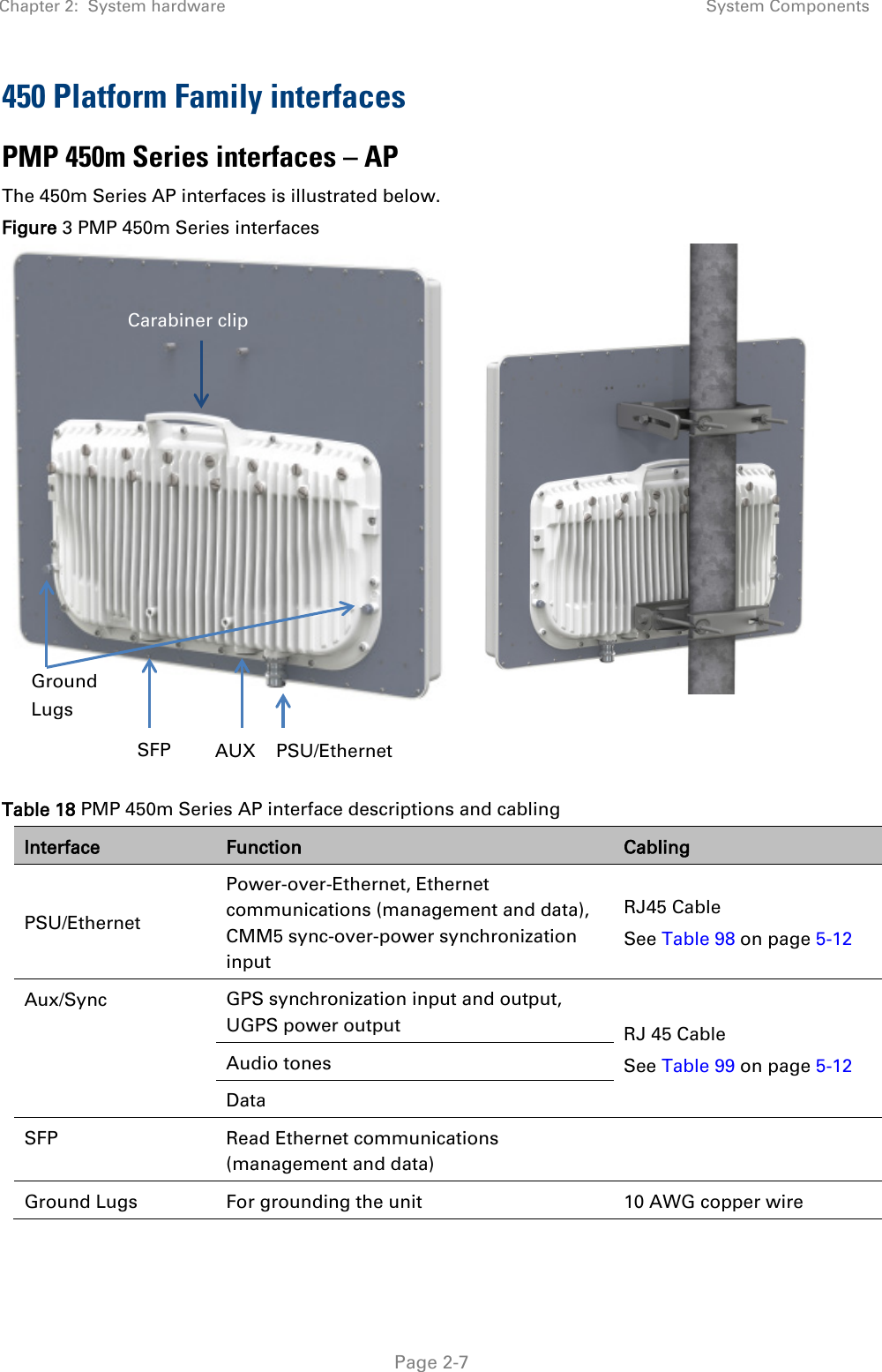
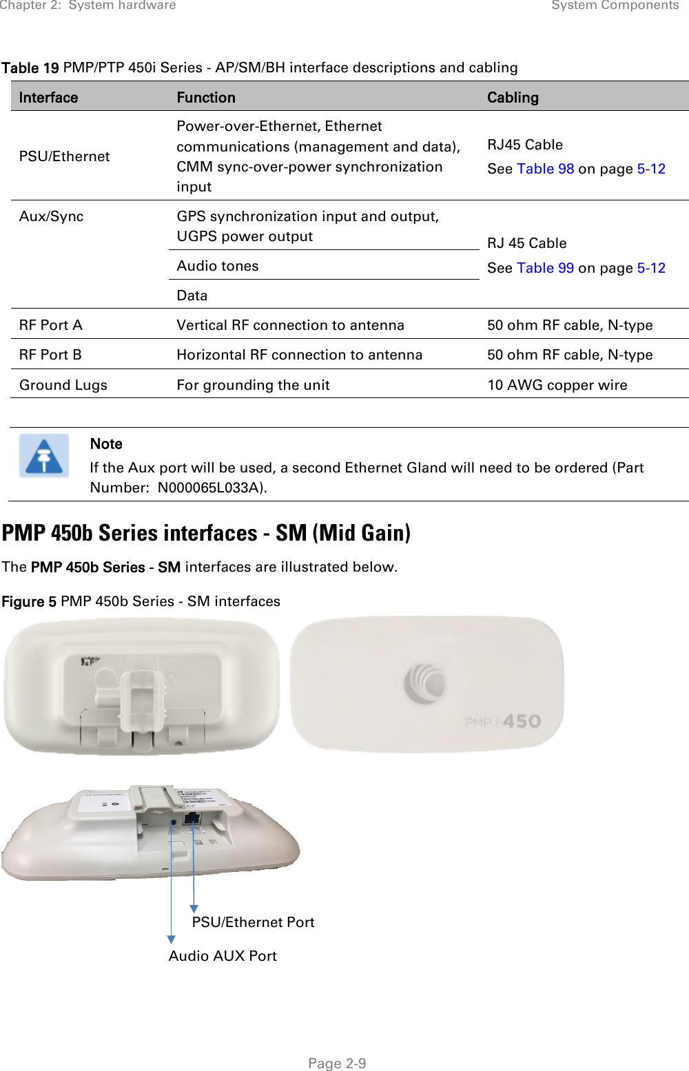
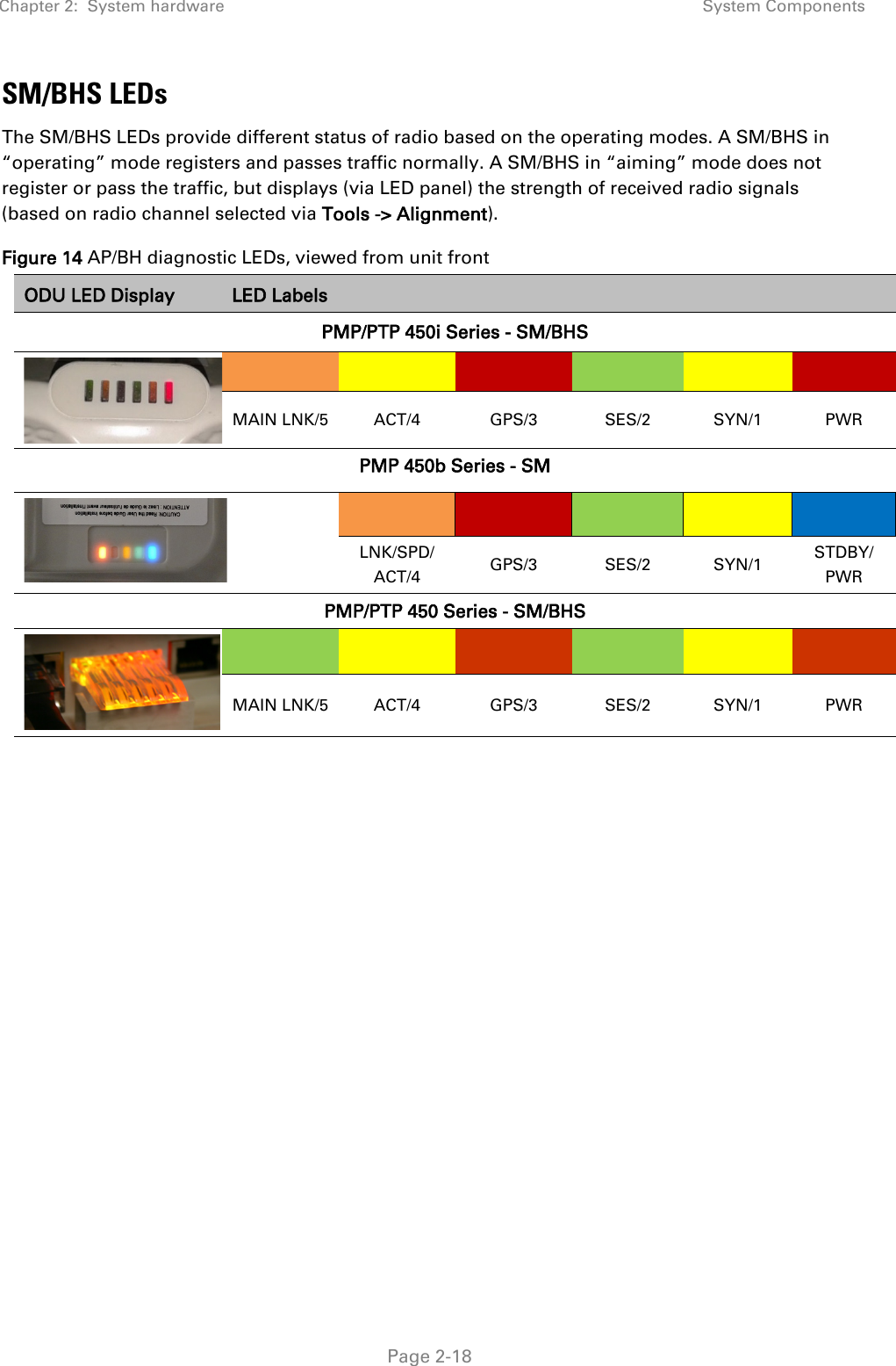
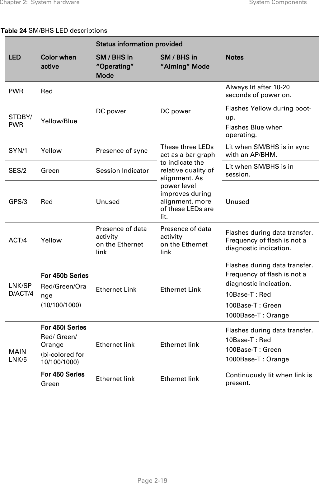
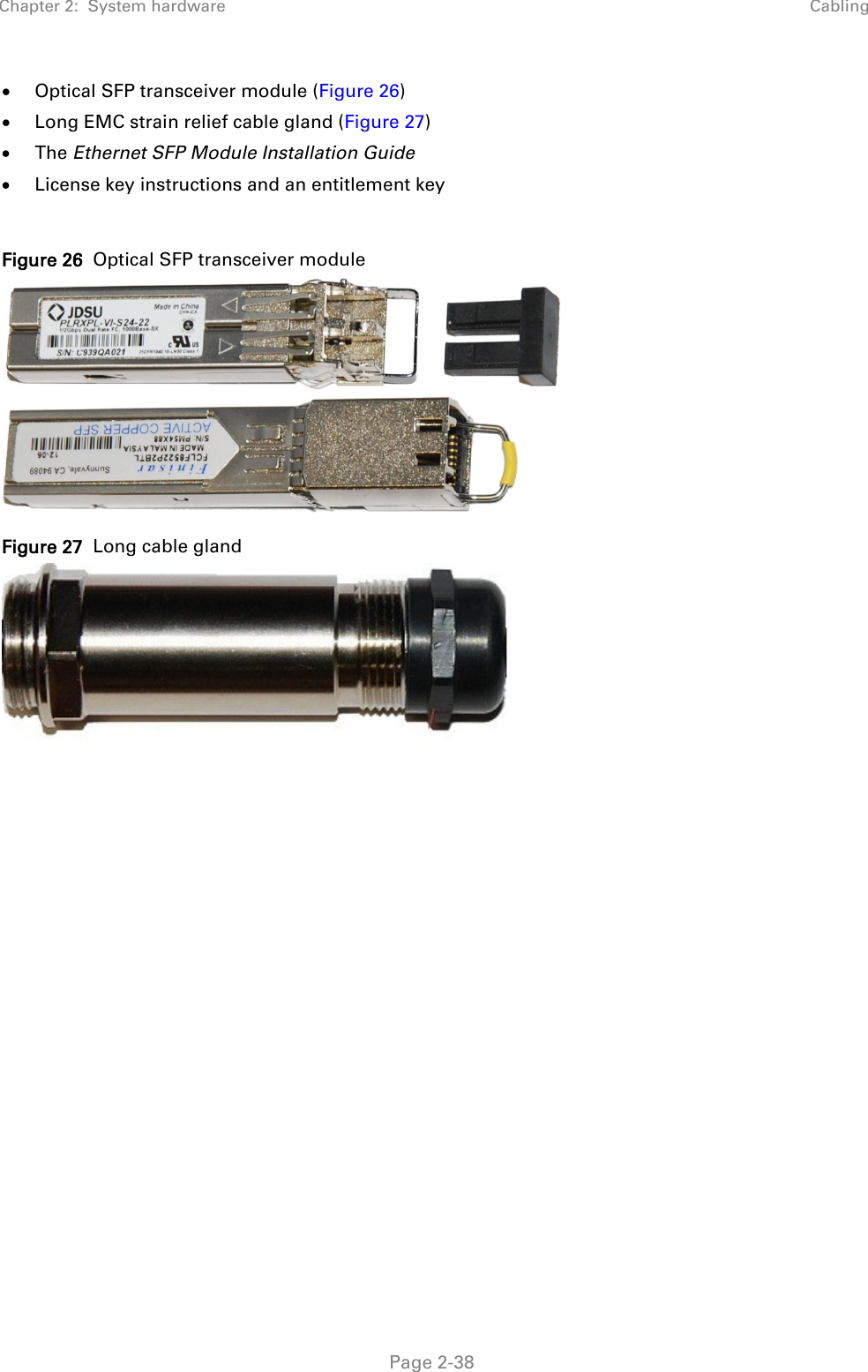
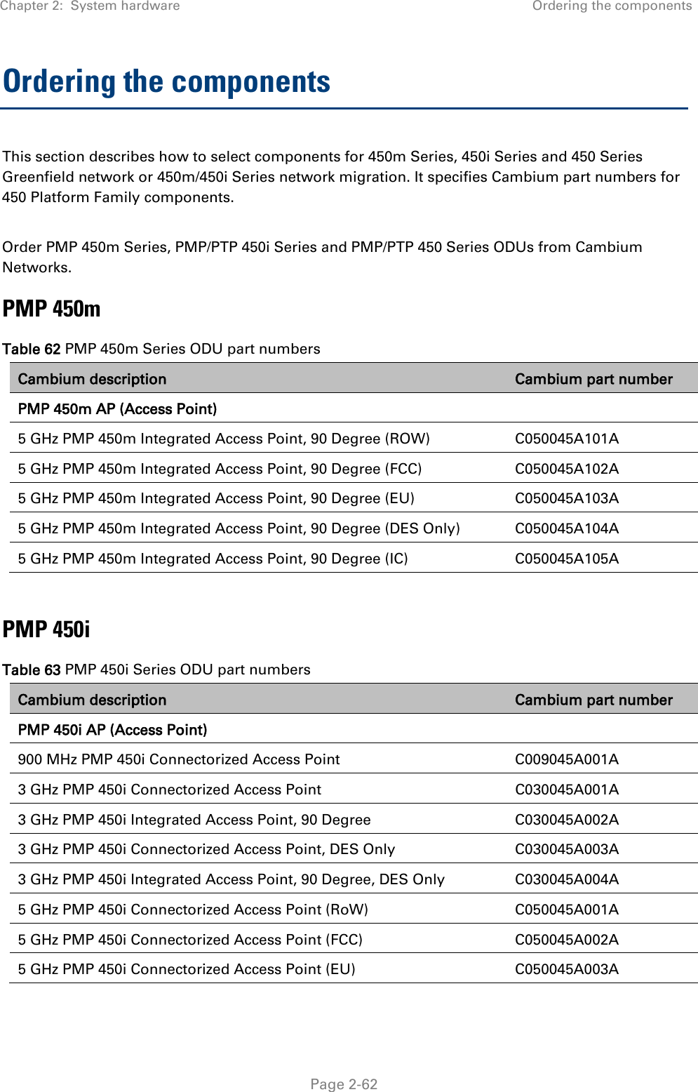
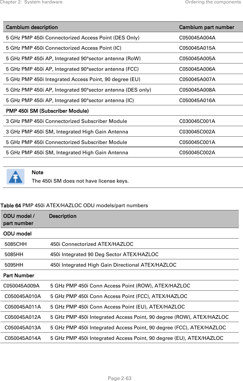
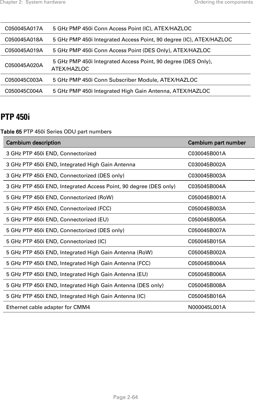
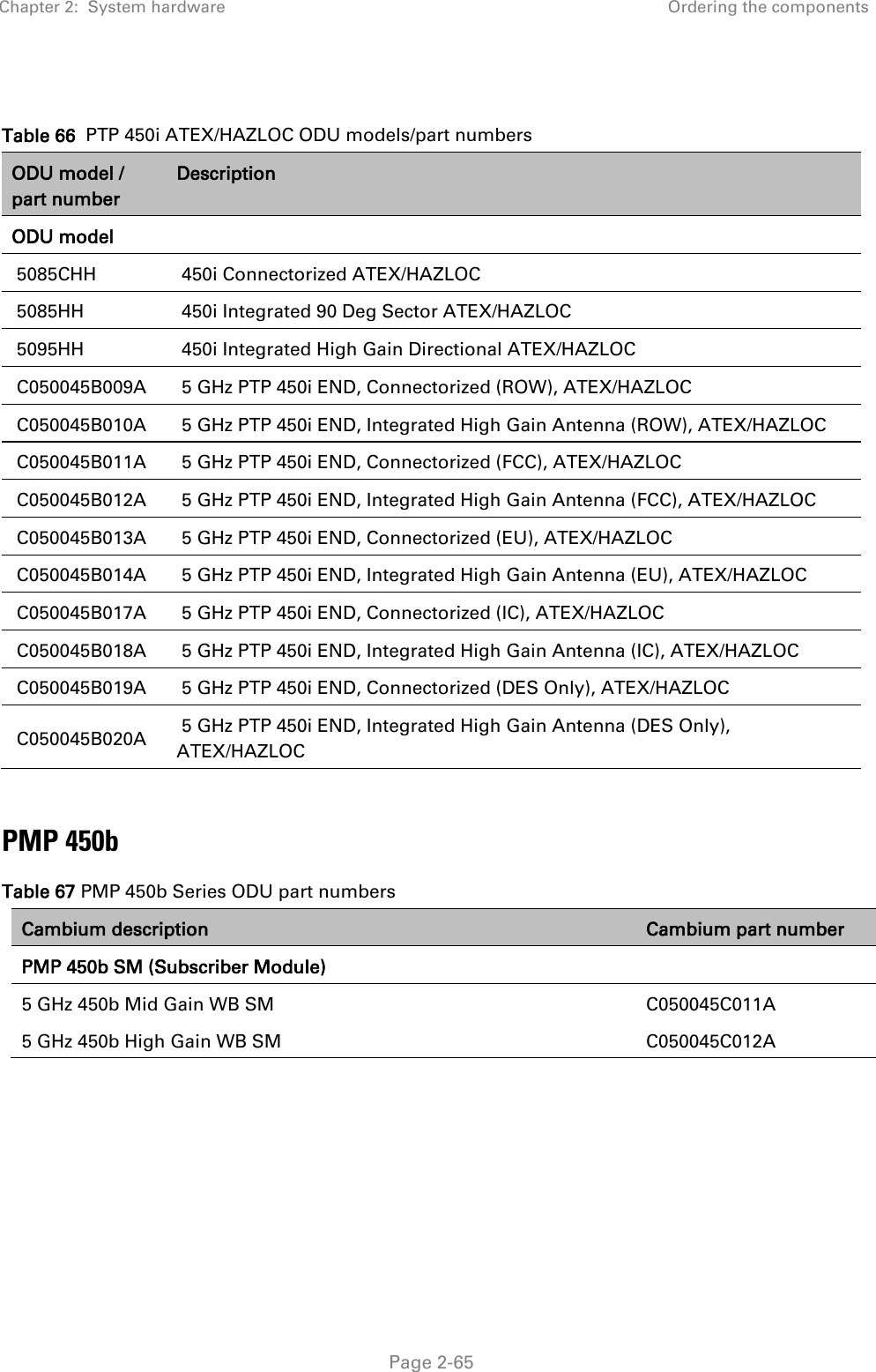
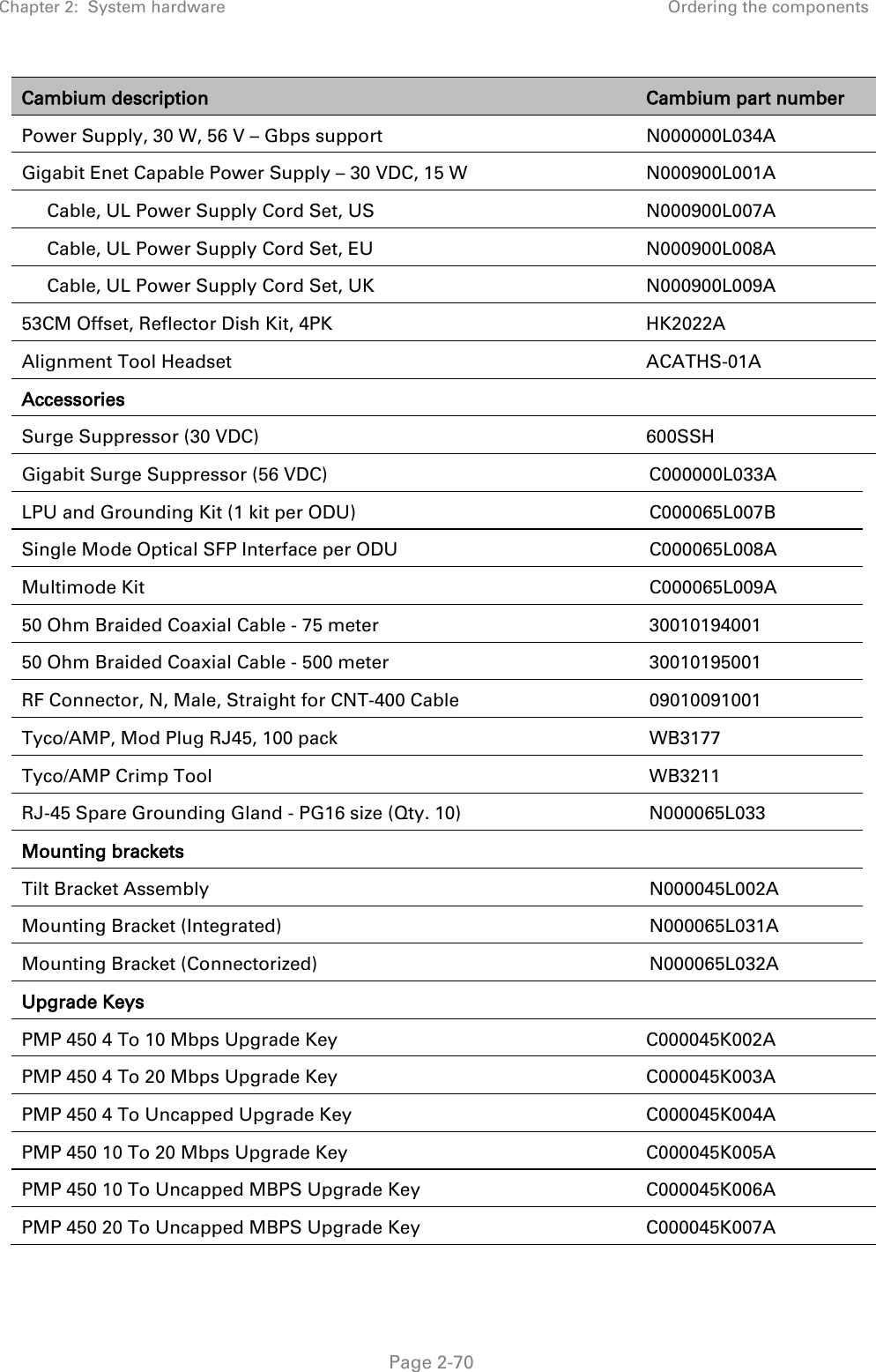
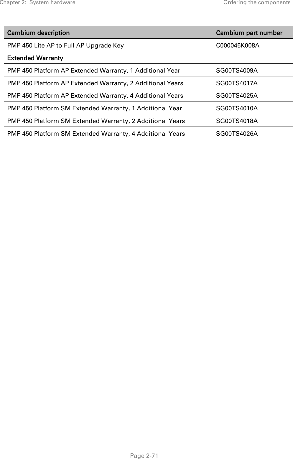
User Manual
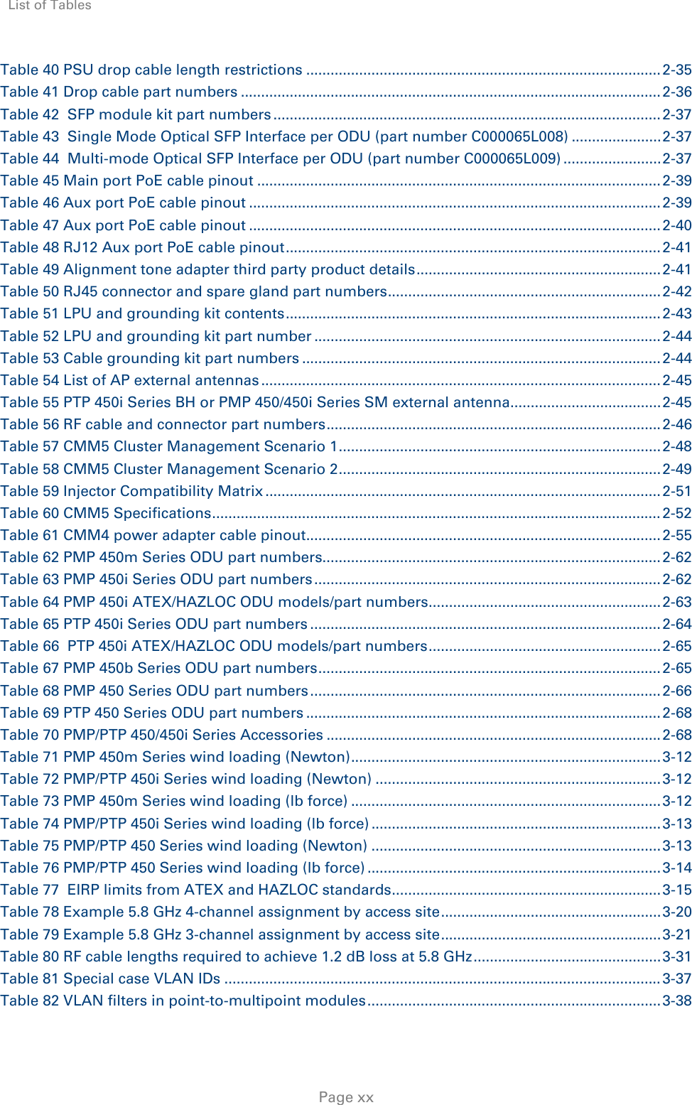
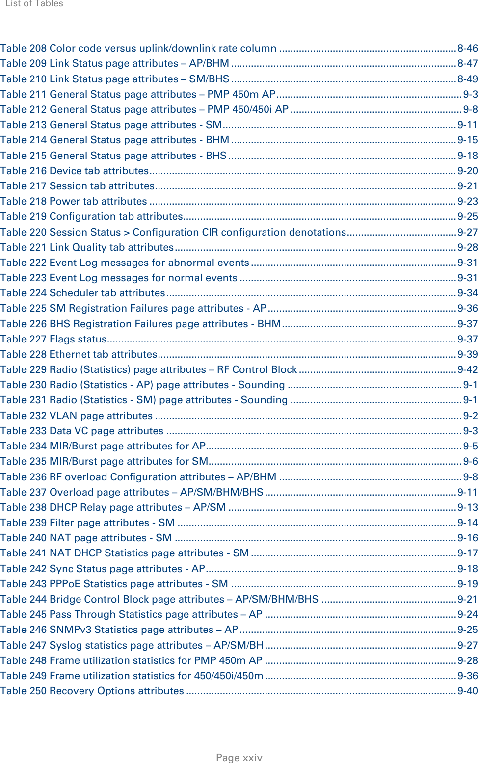
![Page 2 Purpose Cambium Networks Point-to-Multi-Point (PMP)/Point-To-Point (PTP) 450 documents are intended to instruct and assist personnel in the operation, installation and maintenance of the Cambium PMP/PTP equipment and ancillary devices of 450 Platform Family. It is recommended that all personnel engaged in such activities be properly trained. Cambium disclaims all liability whatsoever, implied or express, for any risk of damage, loss or reduction in system performance arising directly or indirectly out of the failure of the customer, or anyone acting on the customer's behalf, to abide by the instructions, system parameters, or recommendations made in this document. Product notation conventions in document This document covers Cambium 450 Series, 450i Series and 450m Series products. The following notation conventions are followed while referring to product series and product family: Product notation Description • 450 Platform Family Refers to the complete 450 Series family, which includes 450 Series, 450i Series, 450b Series and 450m Series • 450 Series Refers to 450 Series devices in the following configurations: - PMP 450 - AP [2.4GHz/3.5 GHz/3.65 GHz /5 GHz] - Connectorized - SM [900 MHz/2.4GHz/3.5 GHz/3.65 GHz /5 GHz] - Connectorized/ Integrated - PTP 450 BHM/ BHS [900 MHz/3.5 GHz/3.65 GHz/5 GHz] - Connectorized/ Integrated - PMP 450d SM [5 GHz] • 450i Series Refers to 450i Series devices in the following configurations: - PMP 450i - AP [900 MHz/3 GHz/5 GHz] - Connectorized/ Integrated - SM [3 GHz/5 GHz] - Connectorized/ Integrated - PTP 450i BHM/ BHS [3 GHz/5 GHz] - Connectorized/ Integrated • 450b Series Refers to 450b Series devices in the following configurations: - PMP 450b - SM [5 GHz] - Integrated](https://usermanual.wiki/Cambium-Networks/50450I.User-Manual/User-Guide-3868901-Page-30.png)