Cambium Networks 50450I Fixed Outdoor Point to Multipoint Transceiver User Manual 450 Platform User Guide
Cambium Networks Limited Fixed Outdoor Point to Multipoint Transceiver 450 Platform User Guide
Contents
- 1. Installation Guide
- 2. User Guide Part 1
- 3. User Guide Part 2
- 4. User Guide Part 3
- 5. User Guide Part 4
- 6. User Guide Part 5
- 7. User Guide Part 6
- 8. User Guide Part 7
- 9. Exhibit D Users Manual per 2 1033 b3
- 10. User Manual - Part 1
- 11. User Manual - Part 2
- 12. User Manual - Part 3
- 13. User Manual - Part 4
- 14. Users Manual - Part 5
- 15. Users Manual - Part 6
- 16. User Manual
Users Manual - Part 5
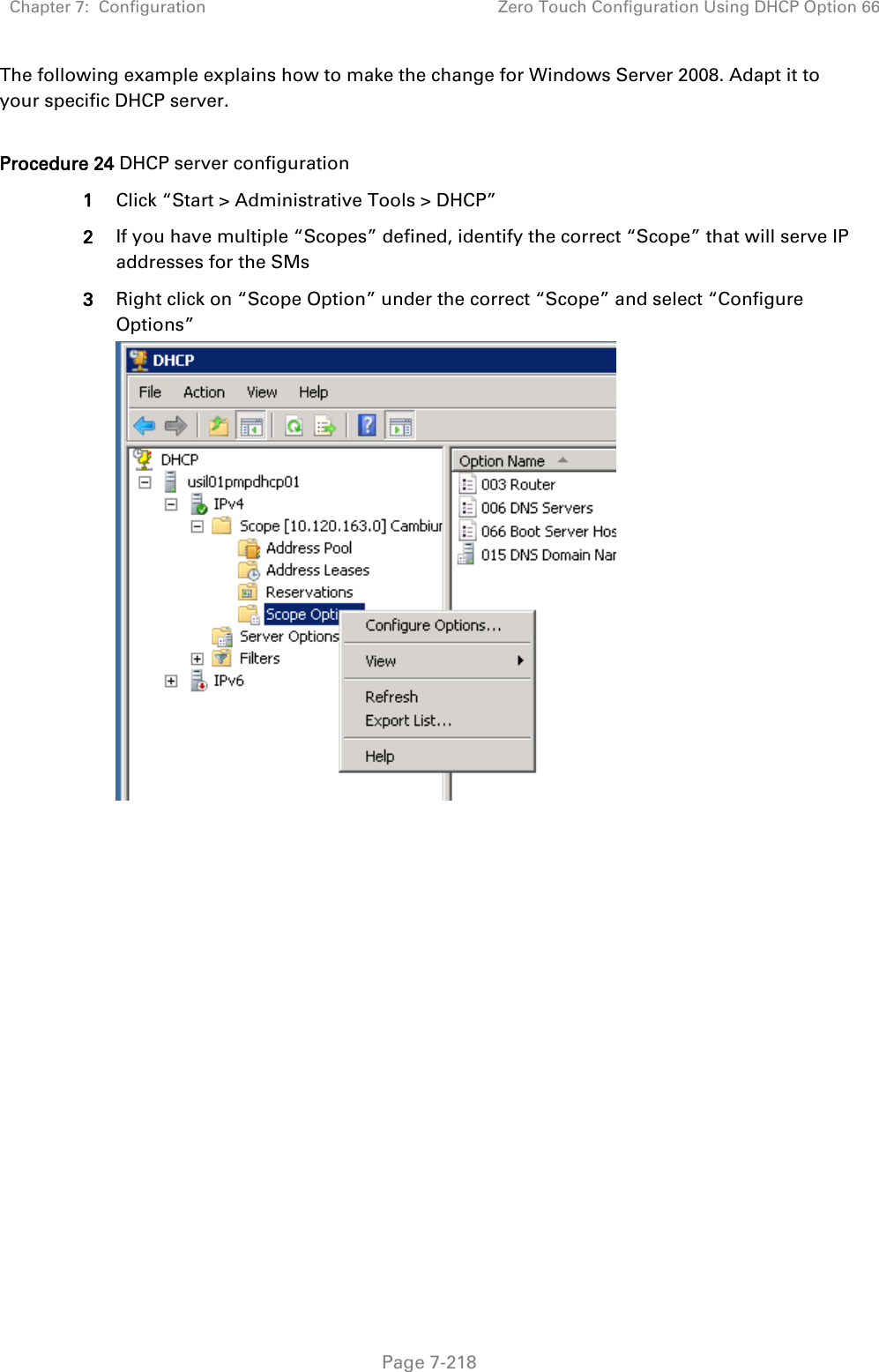
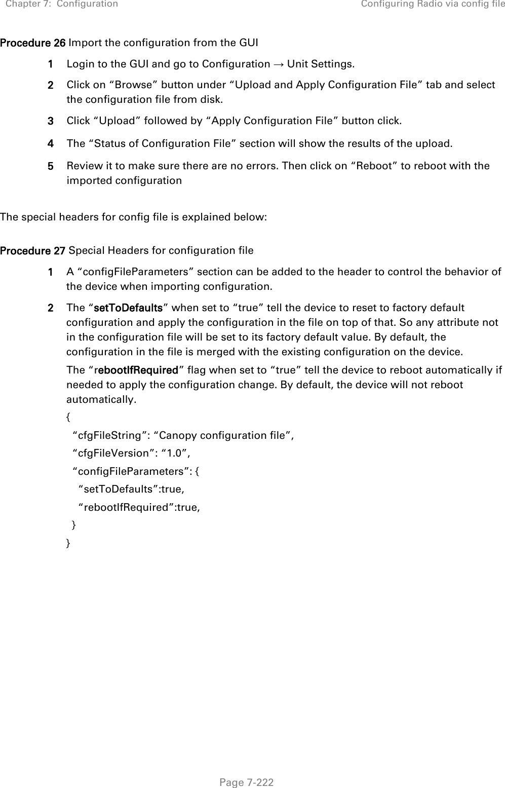
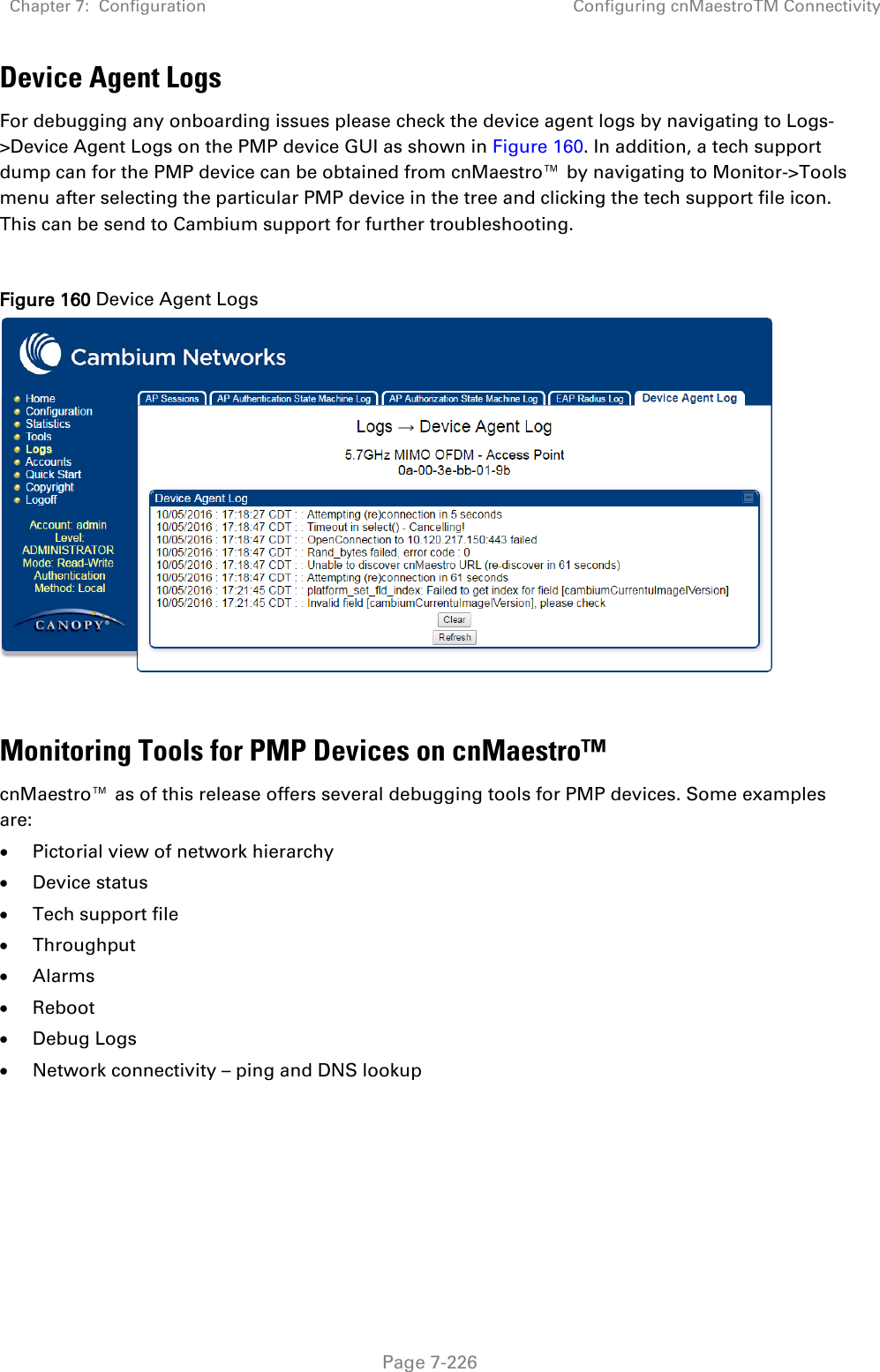
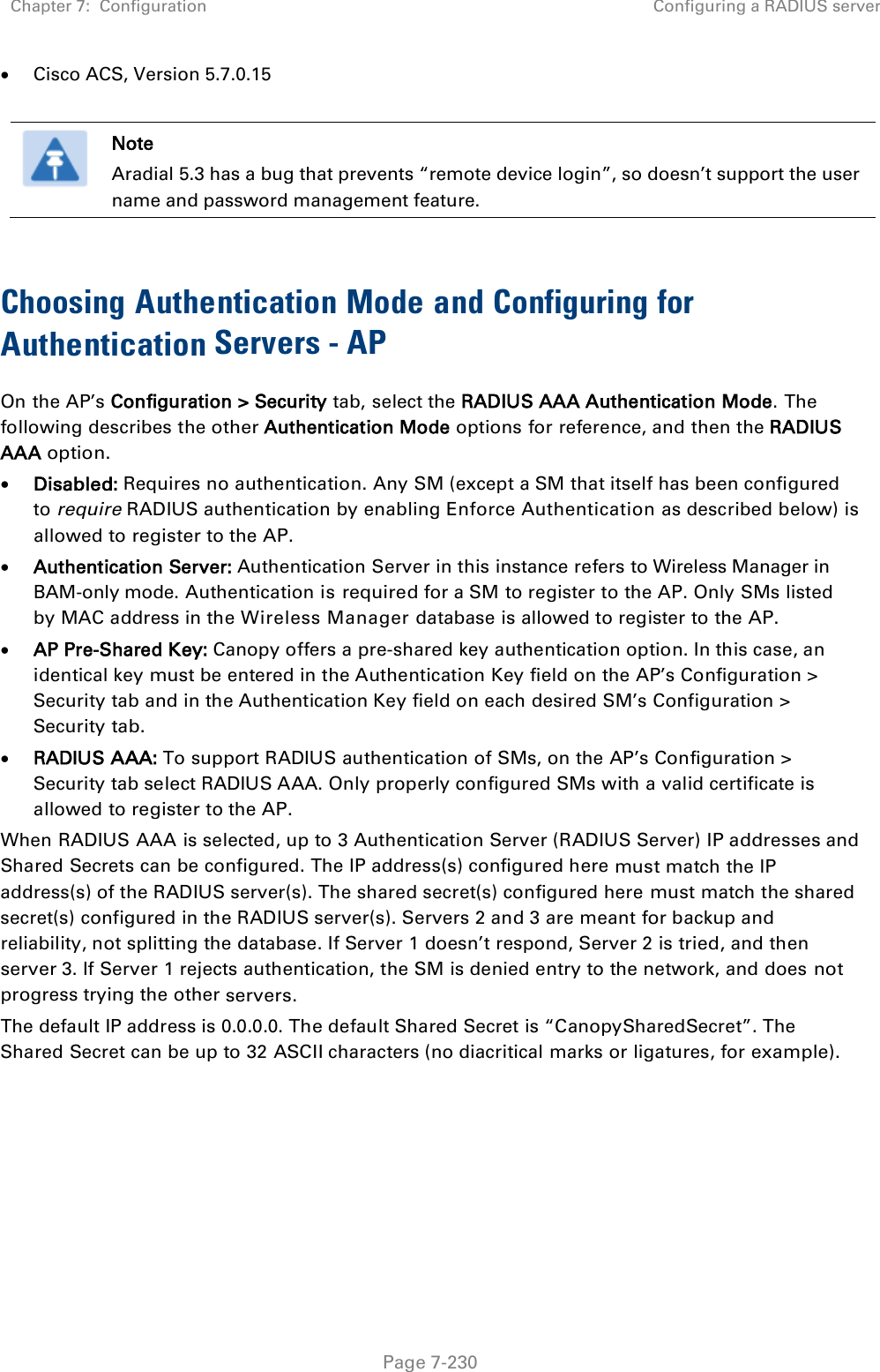
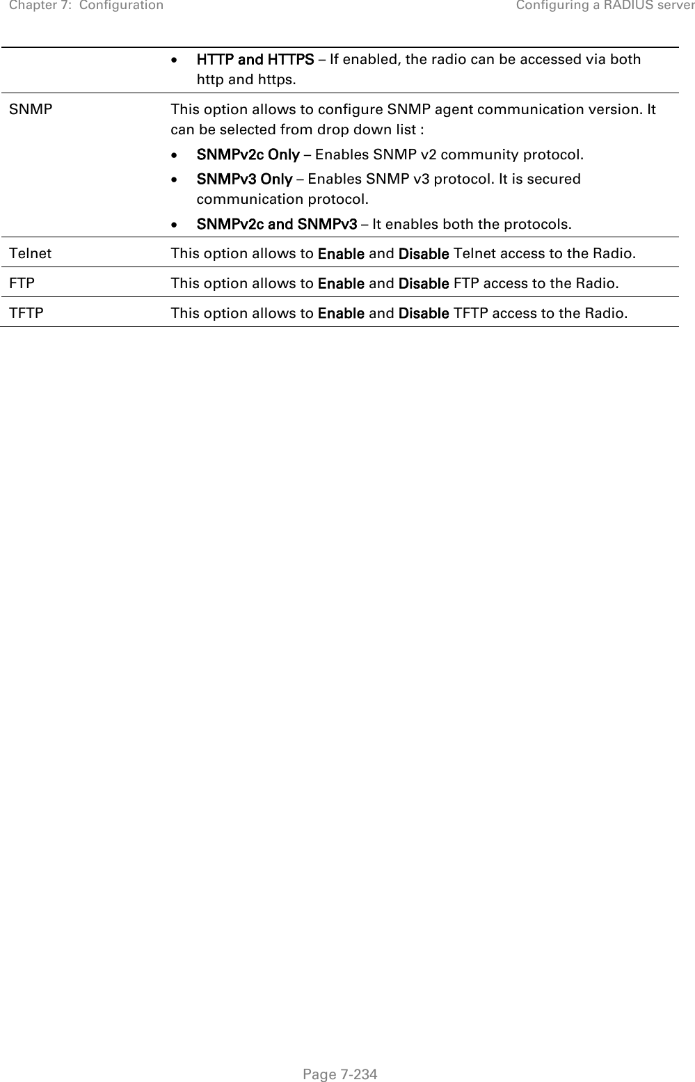
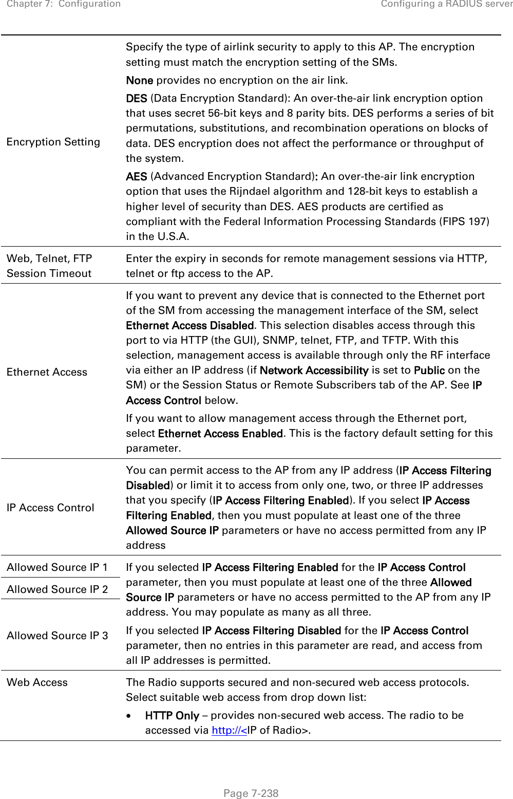
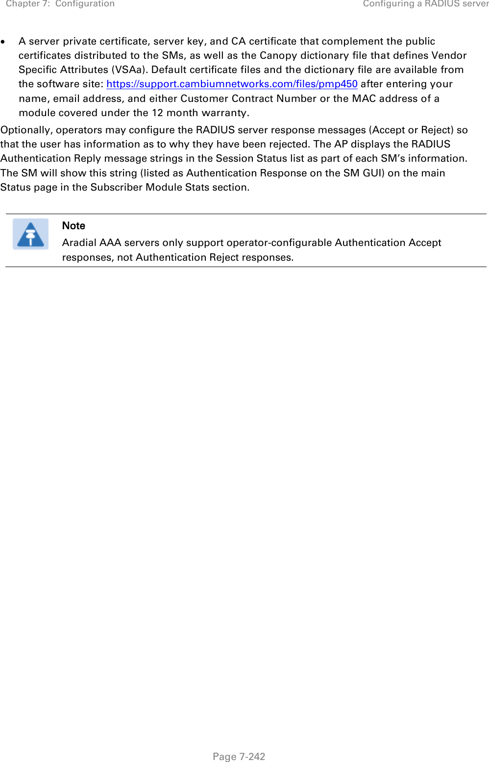
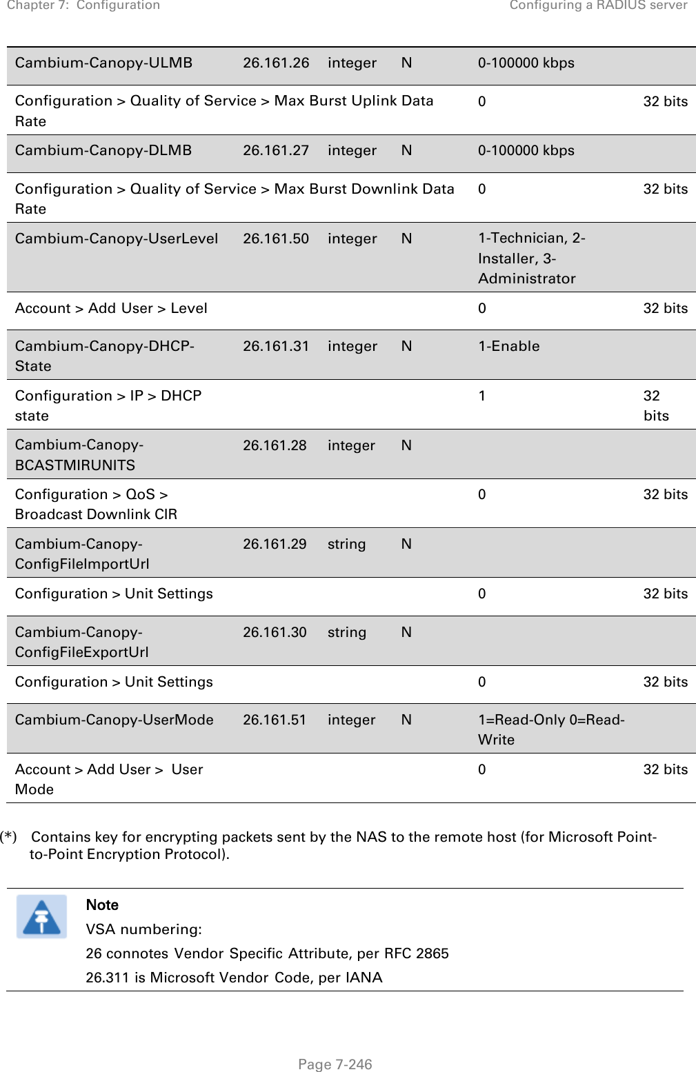
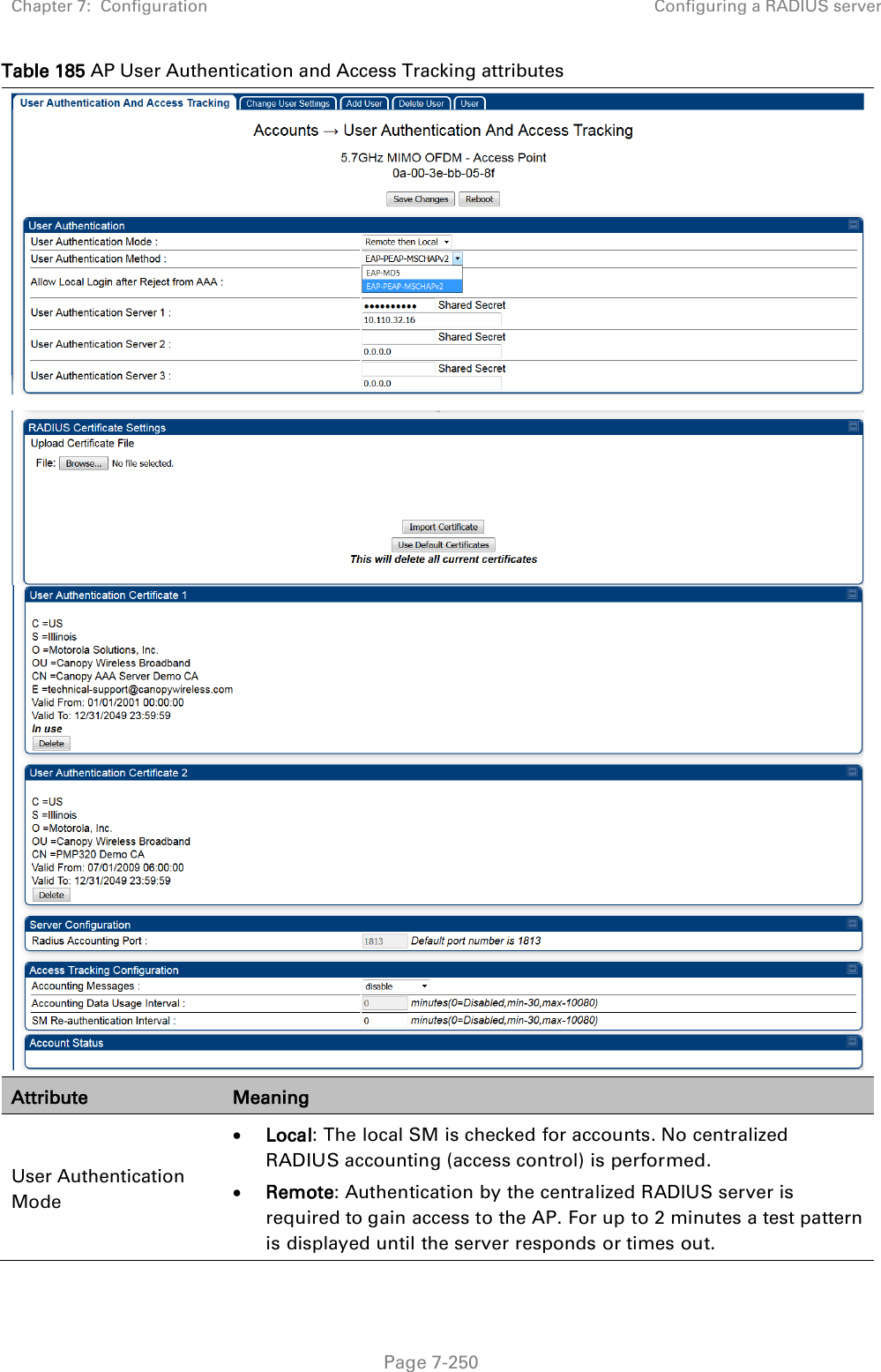
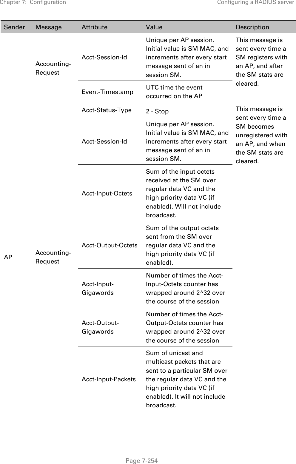
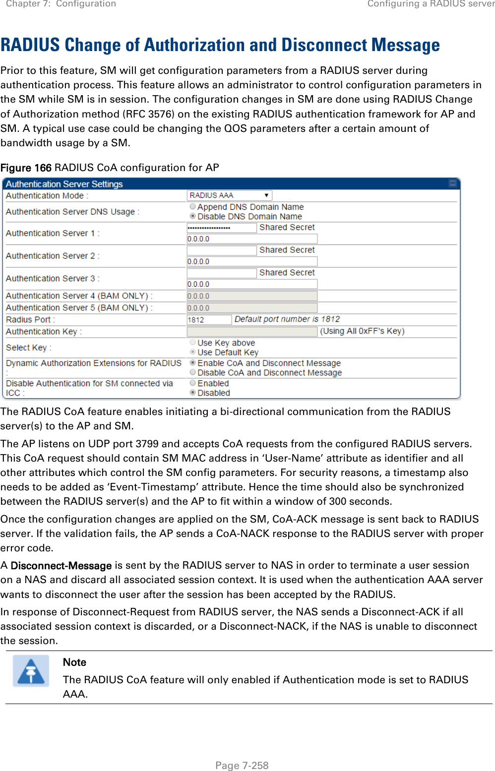
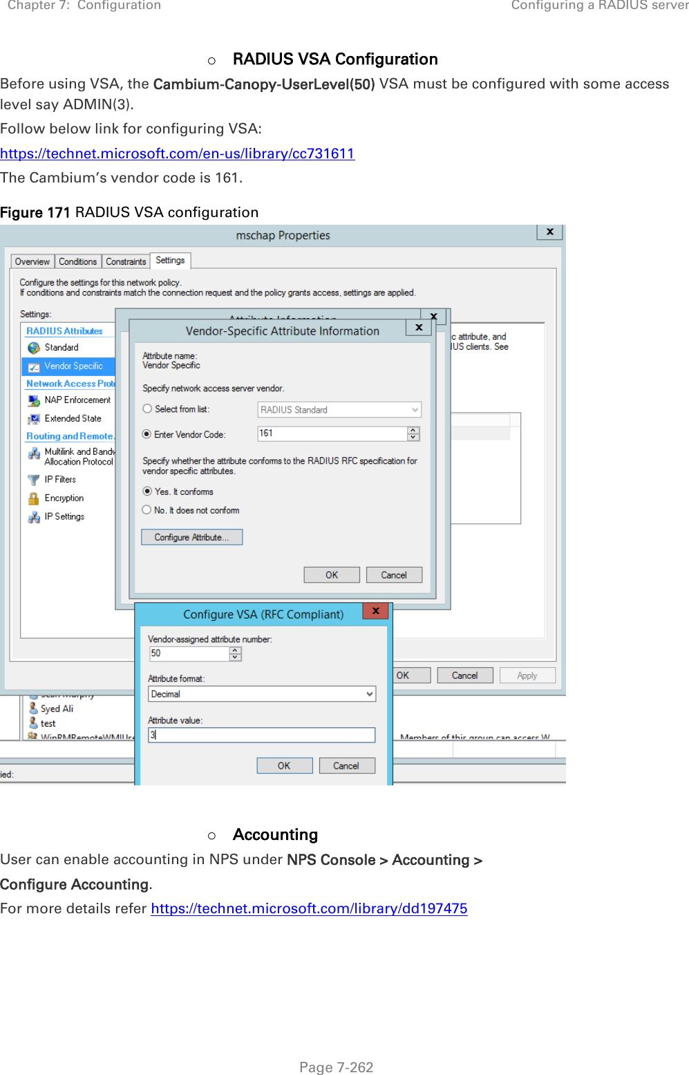
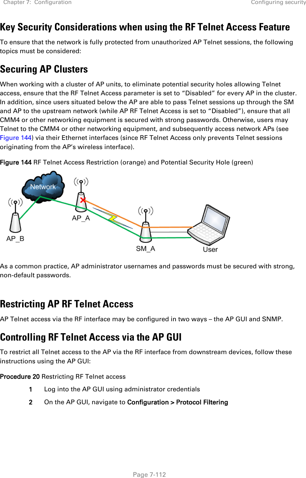
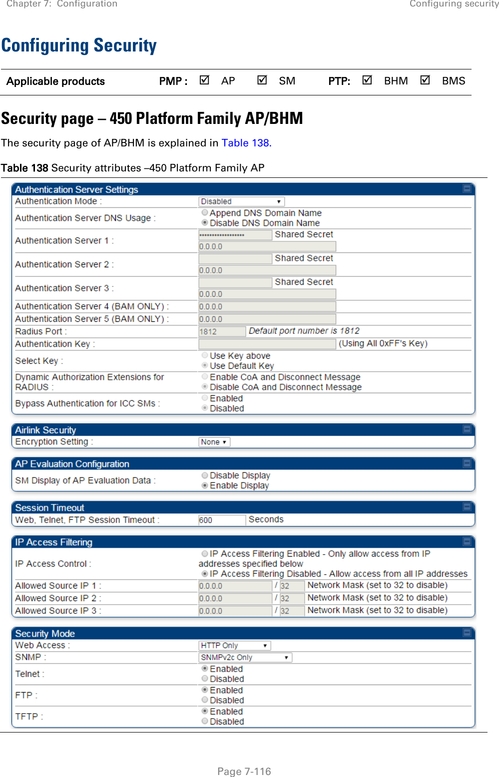
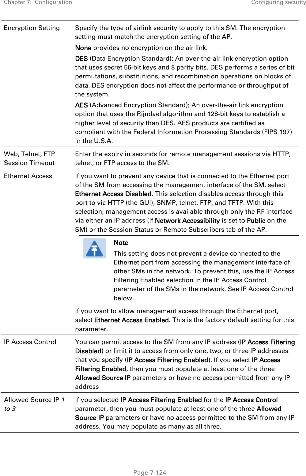
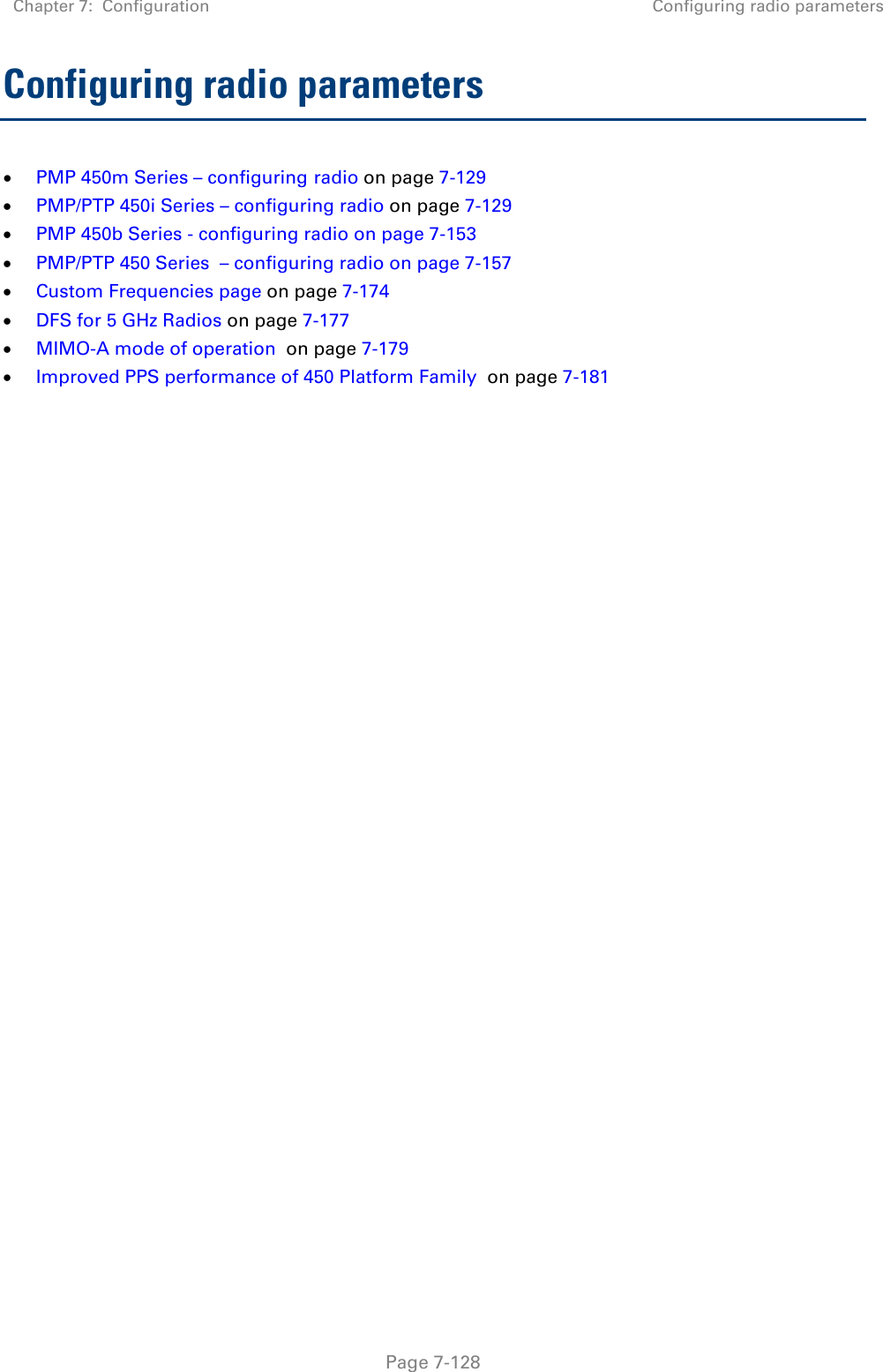
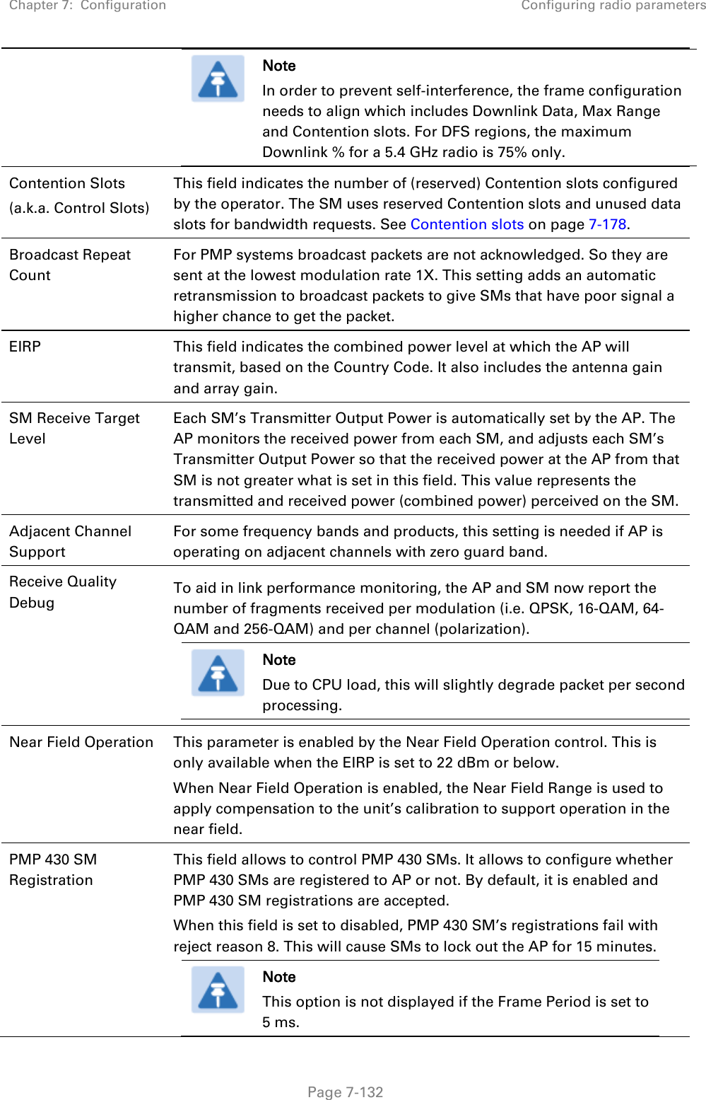
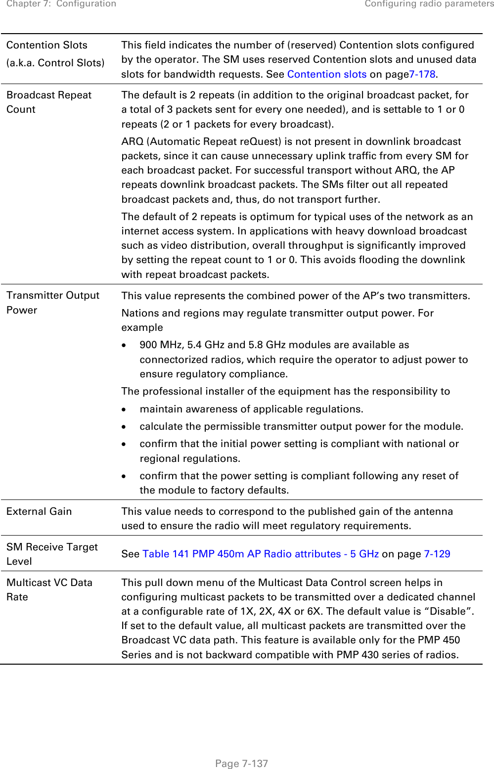
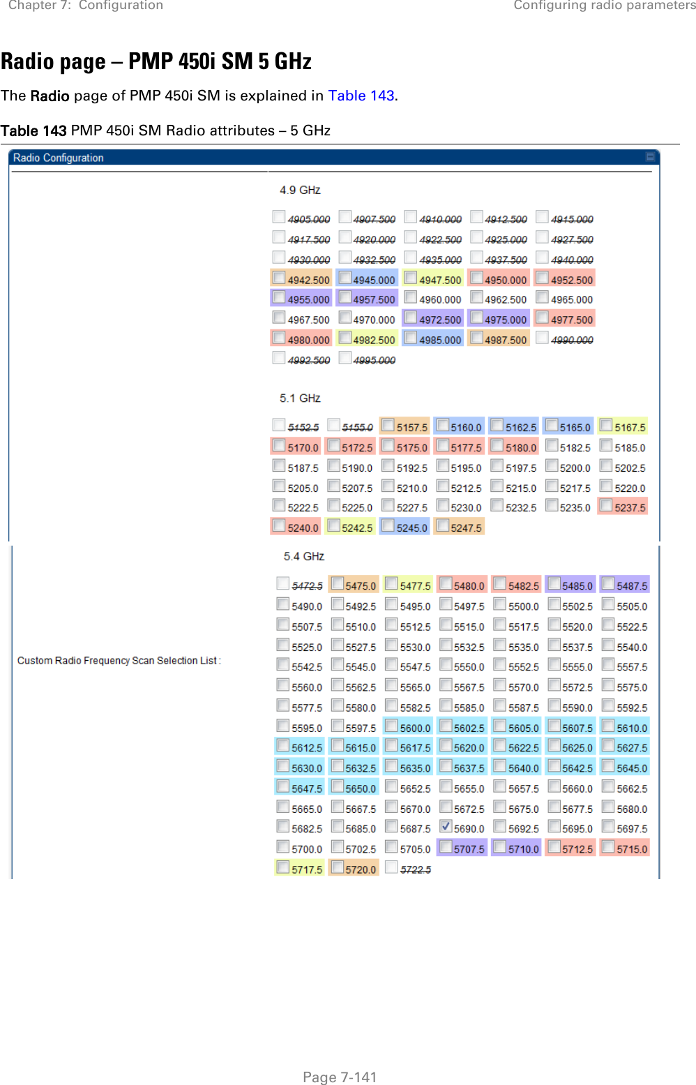
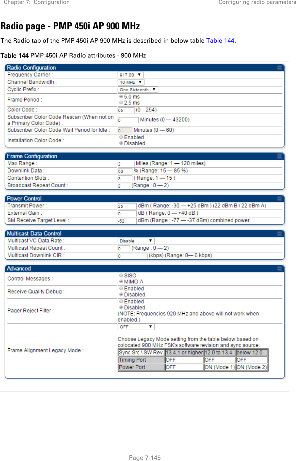
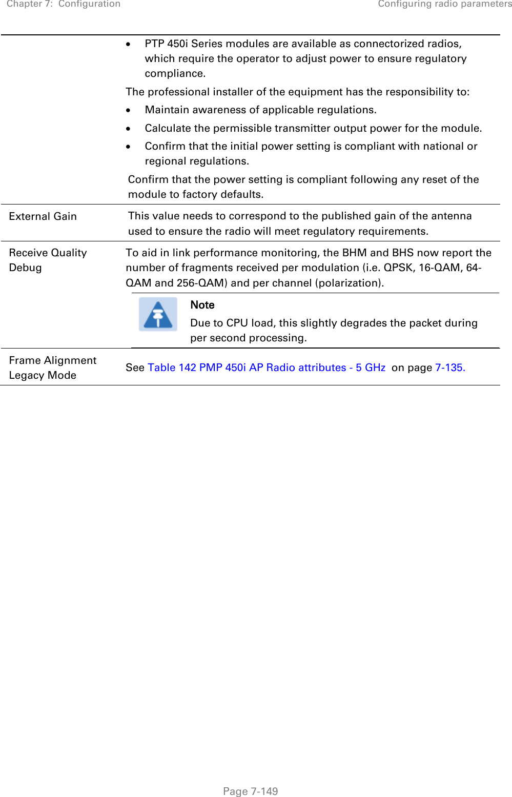
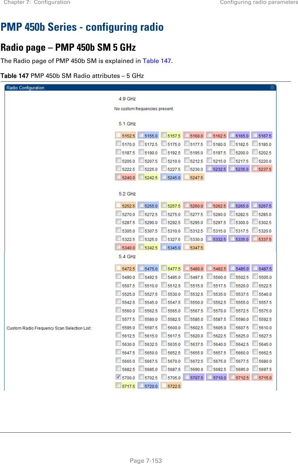
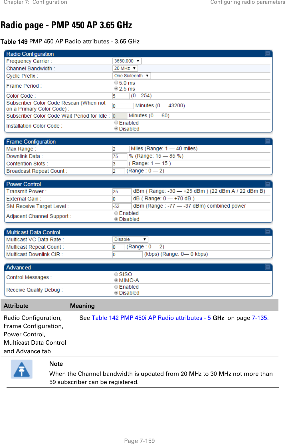
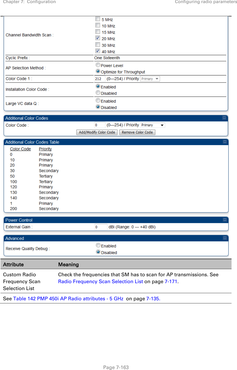
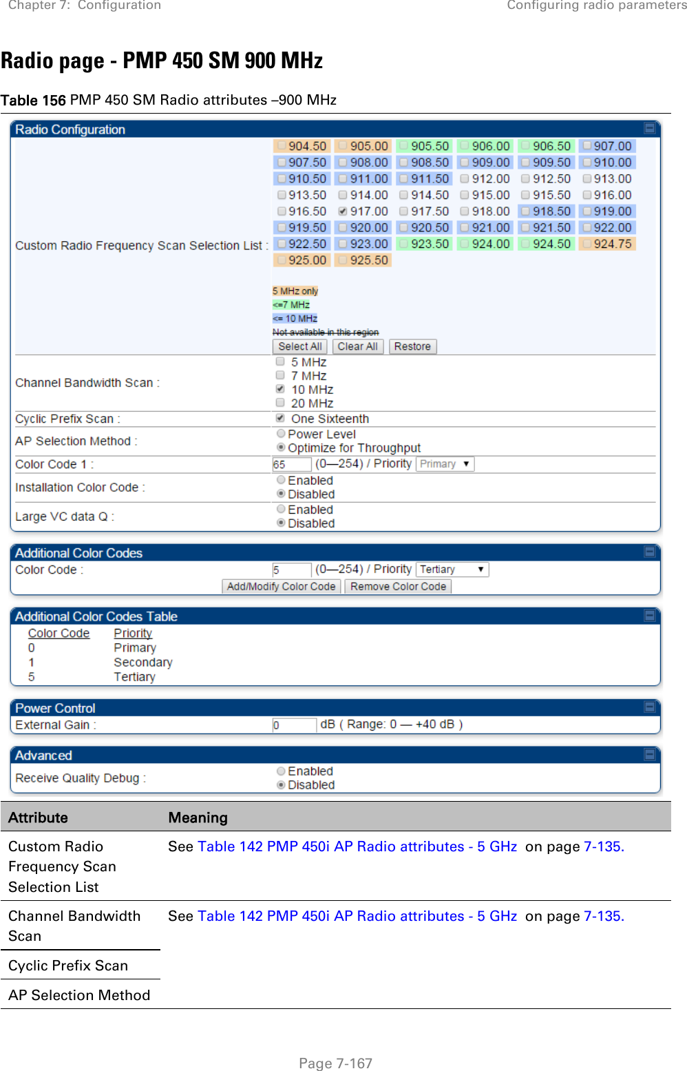
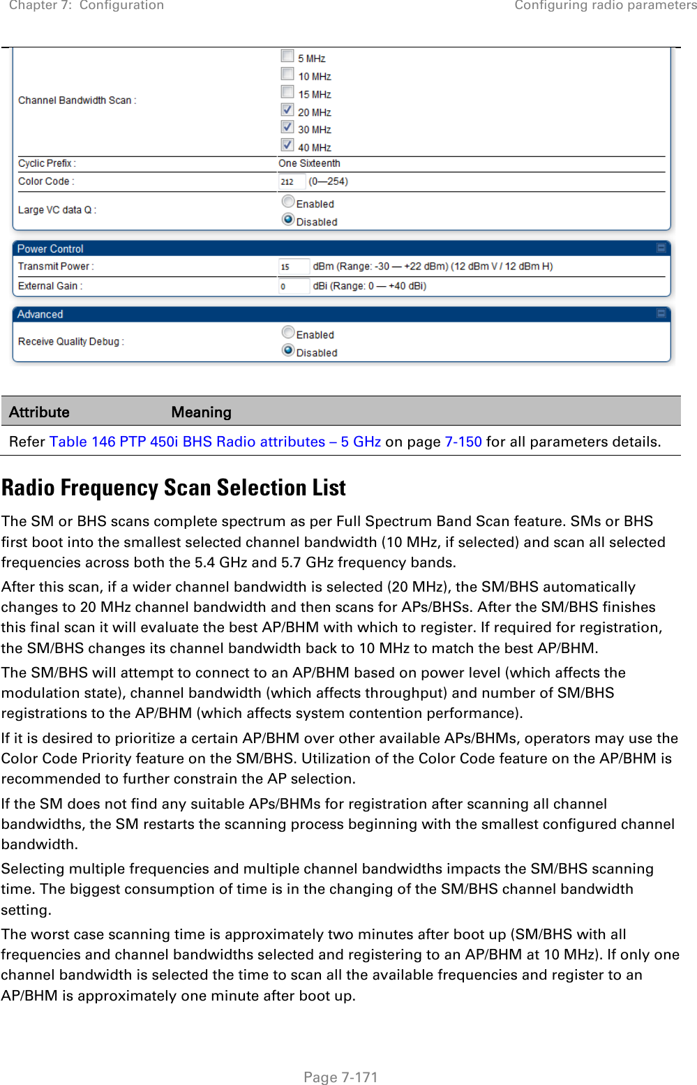
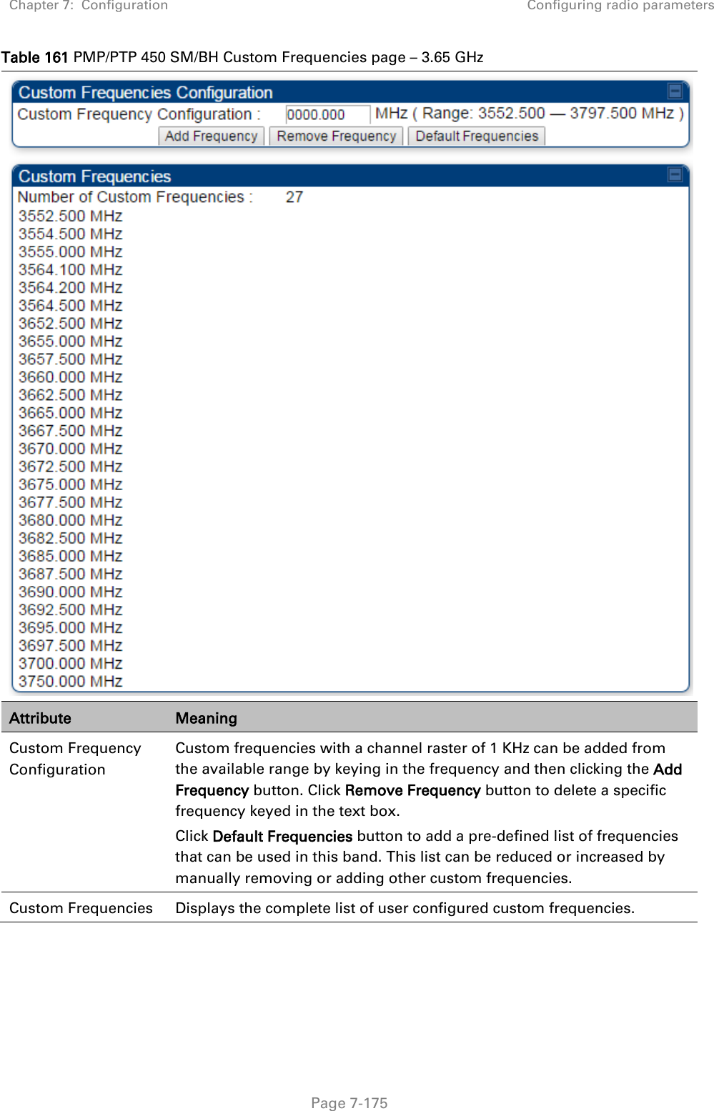
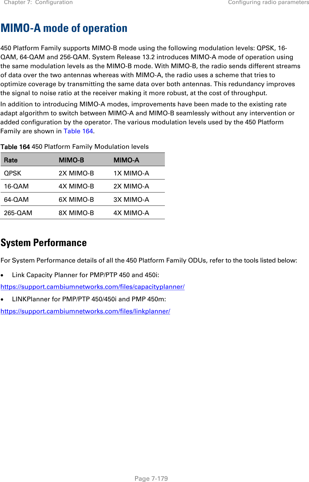
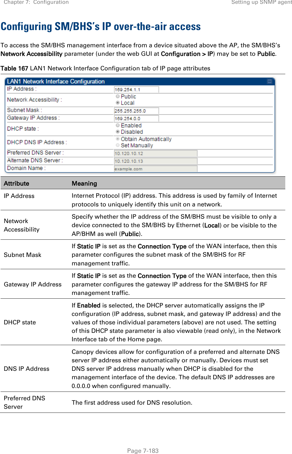
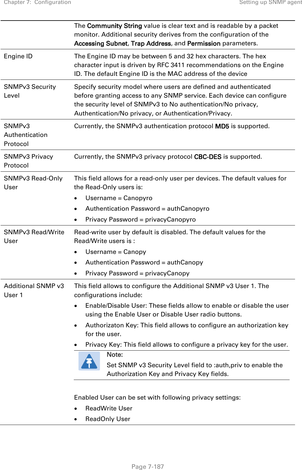
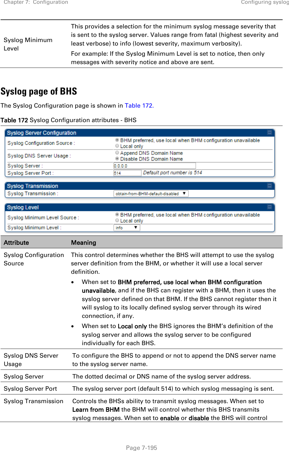
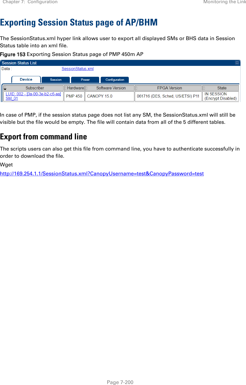
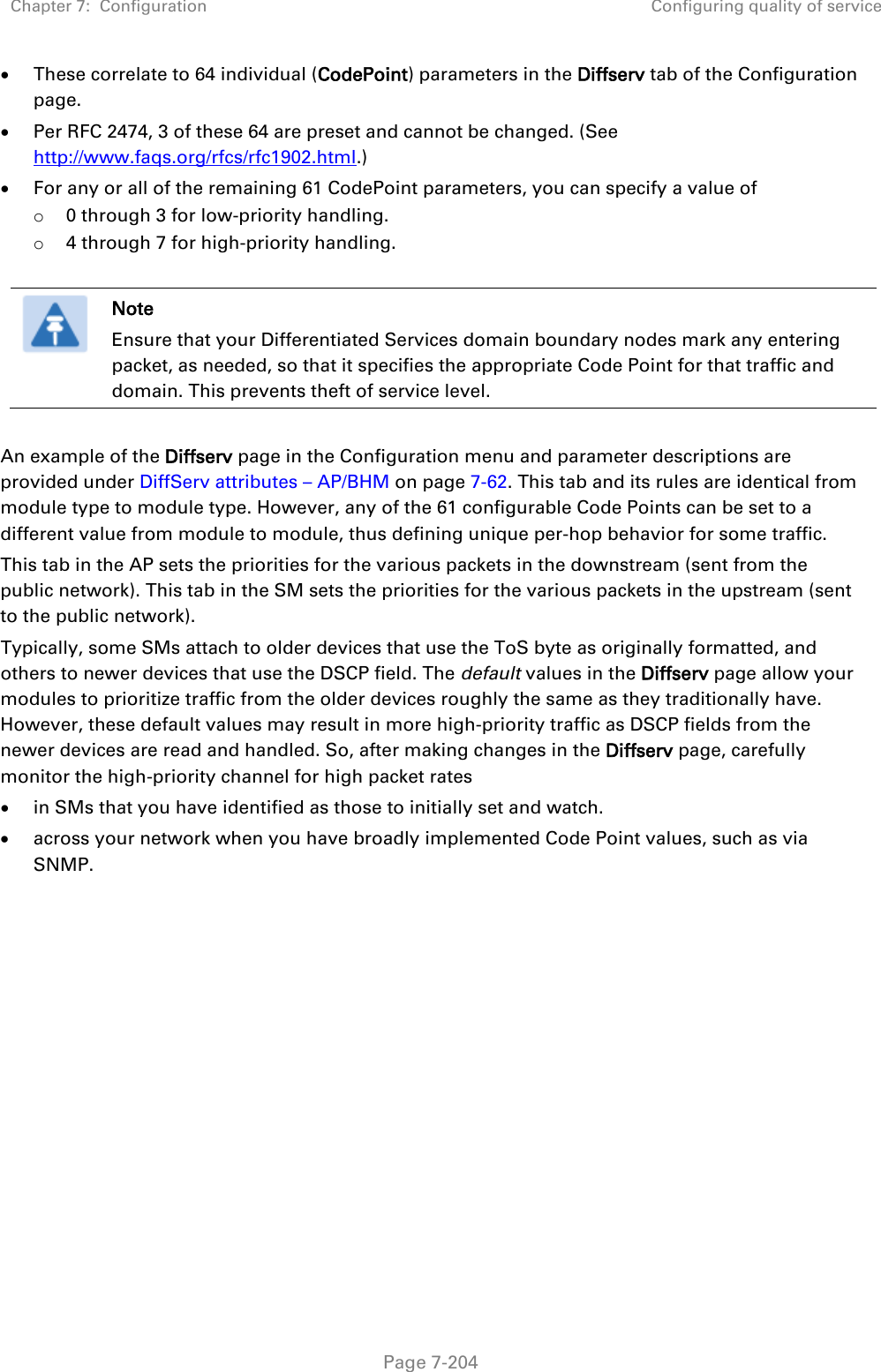
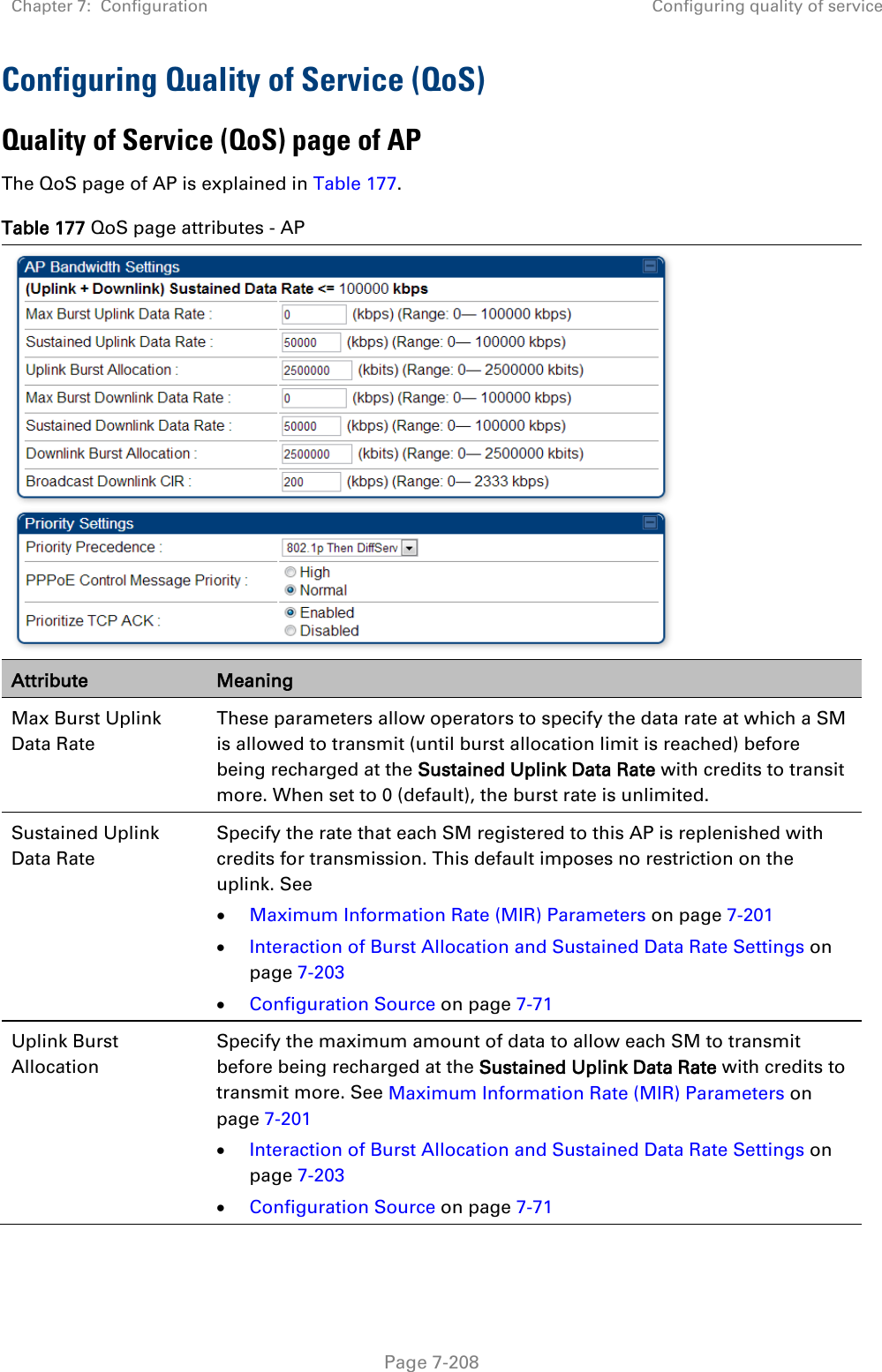
![Chapter 7: Configuration Configuring security Page 7-111 Filtering management through Ethernet See Filtering management through Ethernet on page 3-48. Allowing management only from specified IP addresses See Allowing management from only specified IP addresses on page 3-49. Restricting radio Telnet access over the RF interface RF Telnet Access restricts Telnet access to the AP from a device situated below a network SM (downstream from the AP). This is a security enhancement to restrict RF-interface sourced AP access specifically to the LAN1 IP address and LAN2 IP address (Radio Private Address, typically 192.168.101. [LUID]). This restriction disallows unauthorized users from running Telnet commands on the AP that can change AP configuration or modifying network-critical components such as routing and ARP tables. The RF Telnet Access may be configured via the AP GUI or via SNMP commands, and RF Telnet Access is set to “Enabled” by default. Once RF Telnet Access is set to “Disabled”, if there is a Telnet session attempt to the AP originating from a device situated below the SM (or any downstream device), the attempt is dropped. This also includes Telnet session attempts originated from the SM’s management interface (if a user has initiated a Telnet session to a SM and attempts to Telnet from the SM to the AP). In addition, if there are any active Telnet connections to the AP originating from a device situated below the SM (or any downstream device), the connection is dropped. This behavior must be considered if system administrators use Telnet downstream from an AP (from a registered SM) to modify system parameters. Setting RF Telnet Access to “Disabled” does not affect devices situated above the AP from accessing the AP via Telnet, including servers running the CNUT (Canopy Network Updater tool) application. Also, setting RF Telnet Access to “Disabled” does not affect any Telnet access into upstream devices (situated above or adjacent to the AP) through the AP (see Figure 143). The figure below depicts a user attempting two telnet sessions. One is targeted for the AP (orange) and one is targeted for the network upstream from the AP (green). If RF Telnet Access is set to “Disabled” (factory default setting), the Telnet attempt from the user to the AP is blocked, but the attempt from the user to Network is allowed to pass through the Cambium network. Figure 143 RF Telnet Access Restrictions (orange) and Flow through (green)](https://usermanual.wiki/Cambium-Networks/50450I.Users-Manual-Part-5/User-Guide-3815623-Page-2.png)
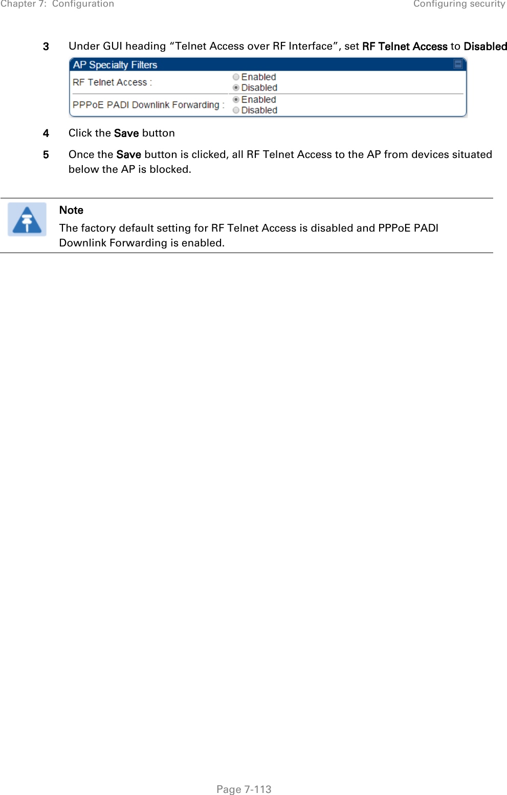
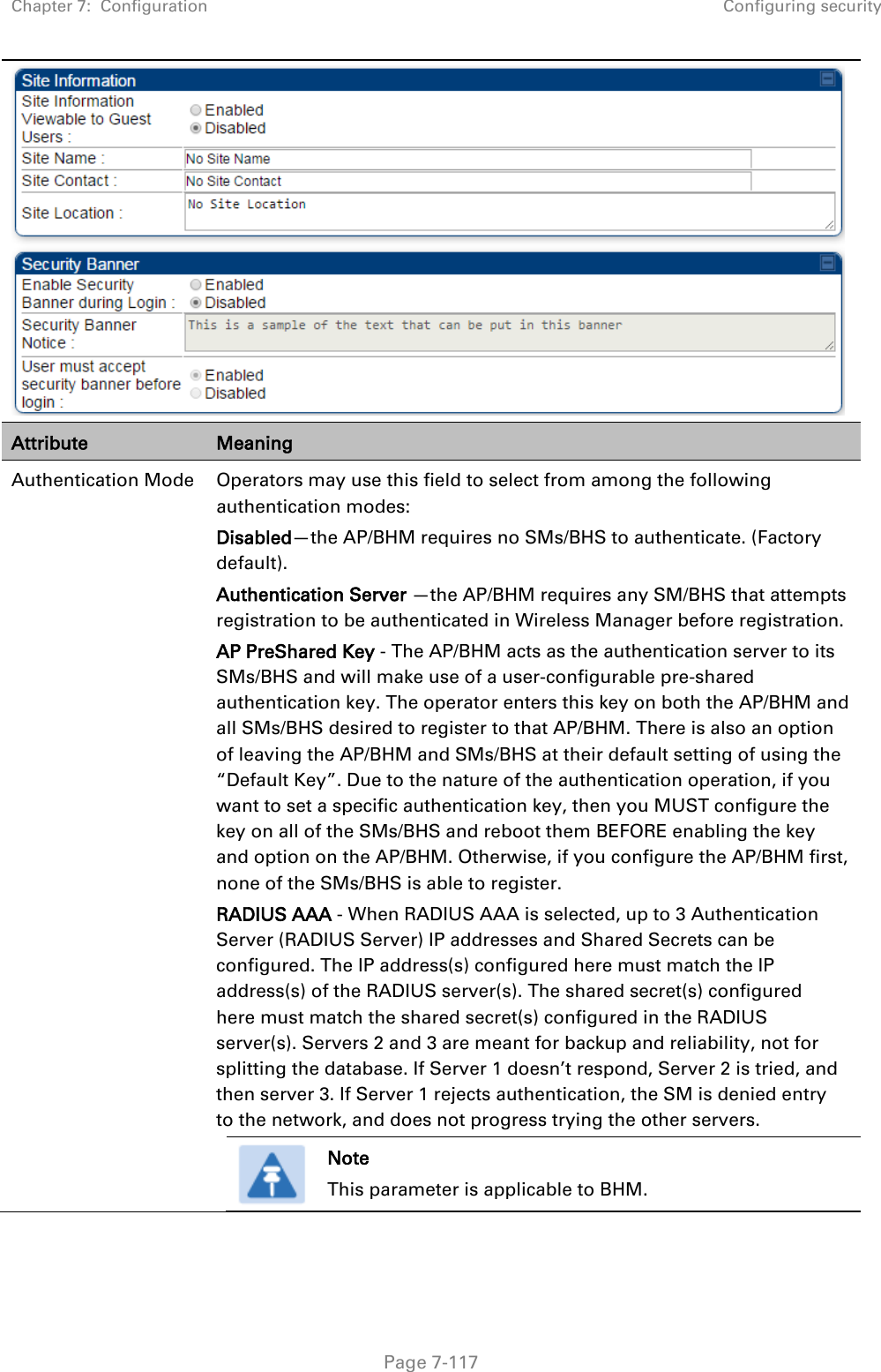
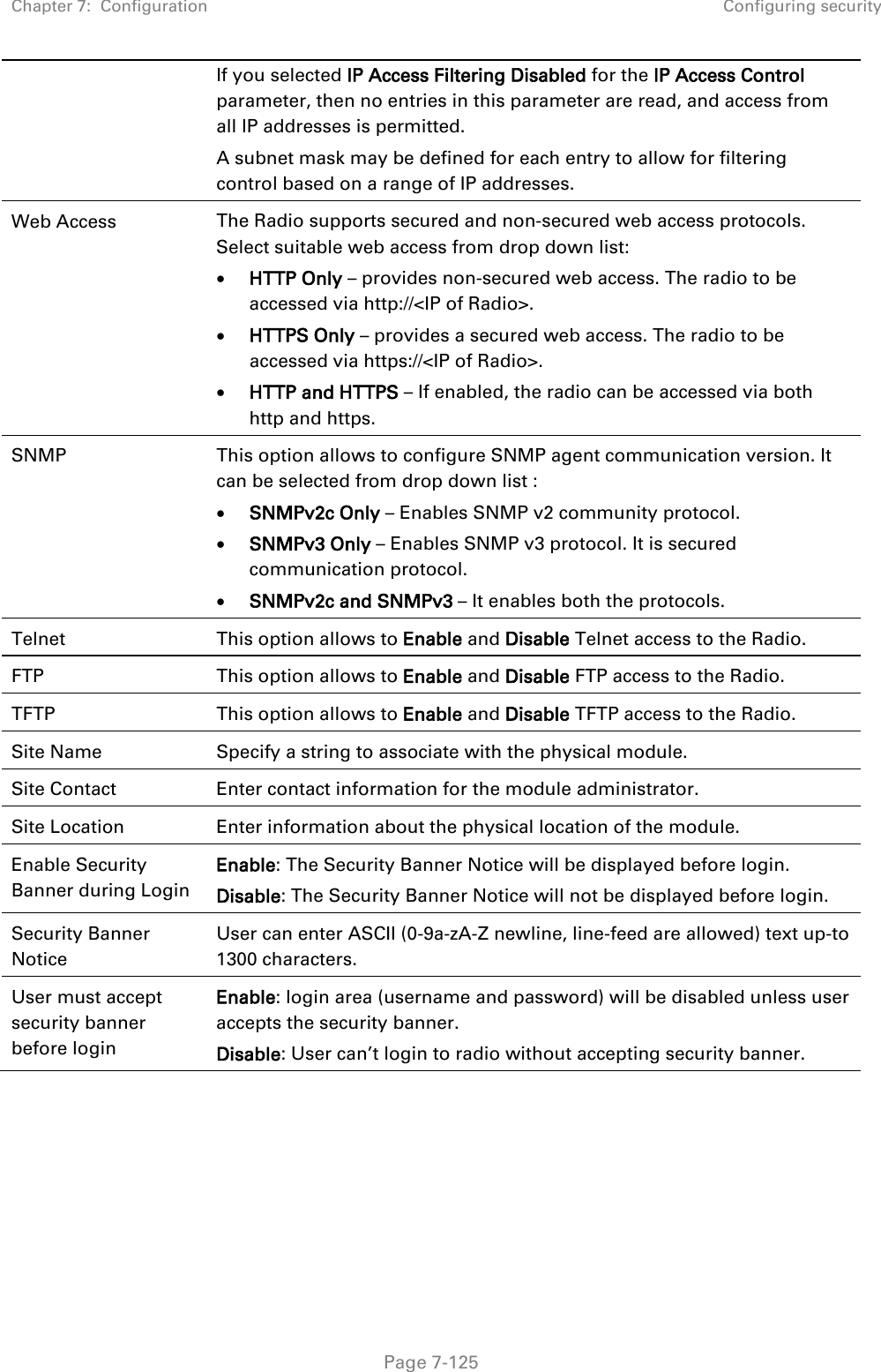
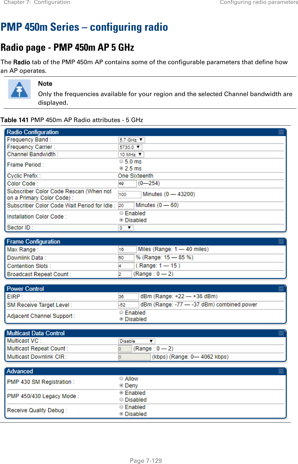
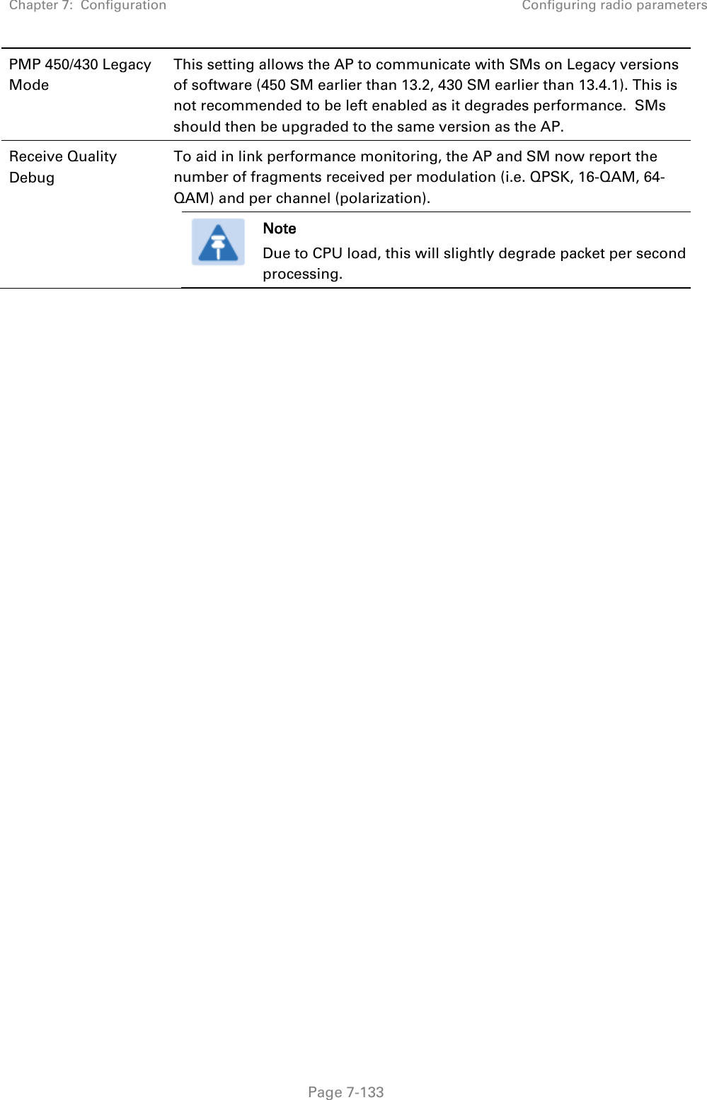

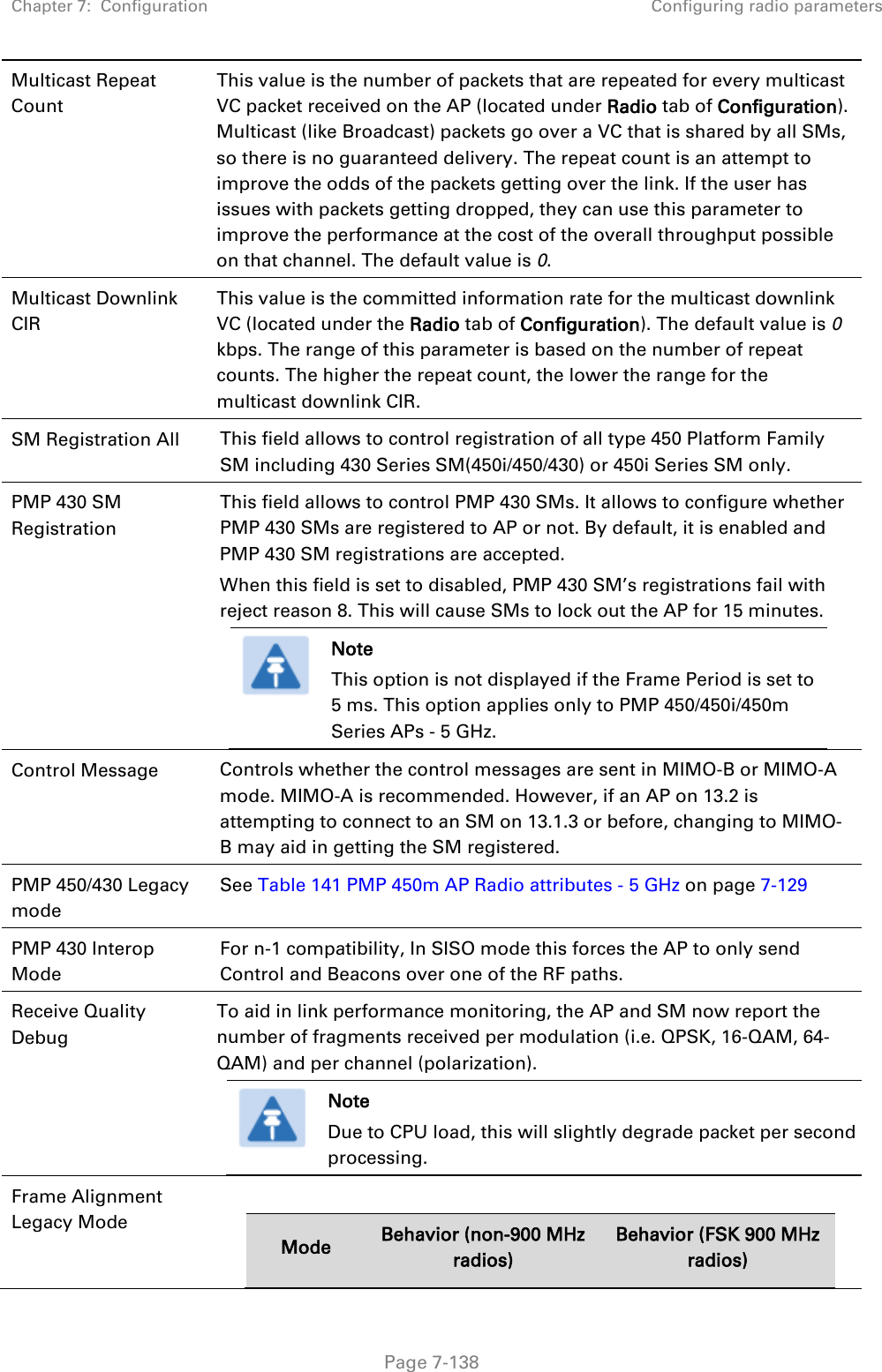
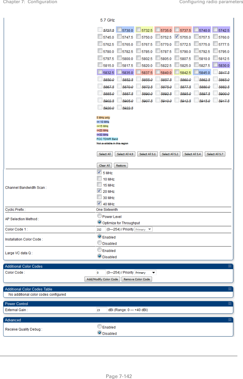
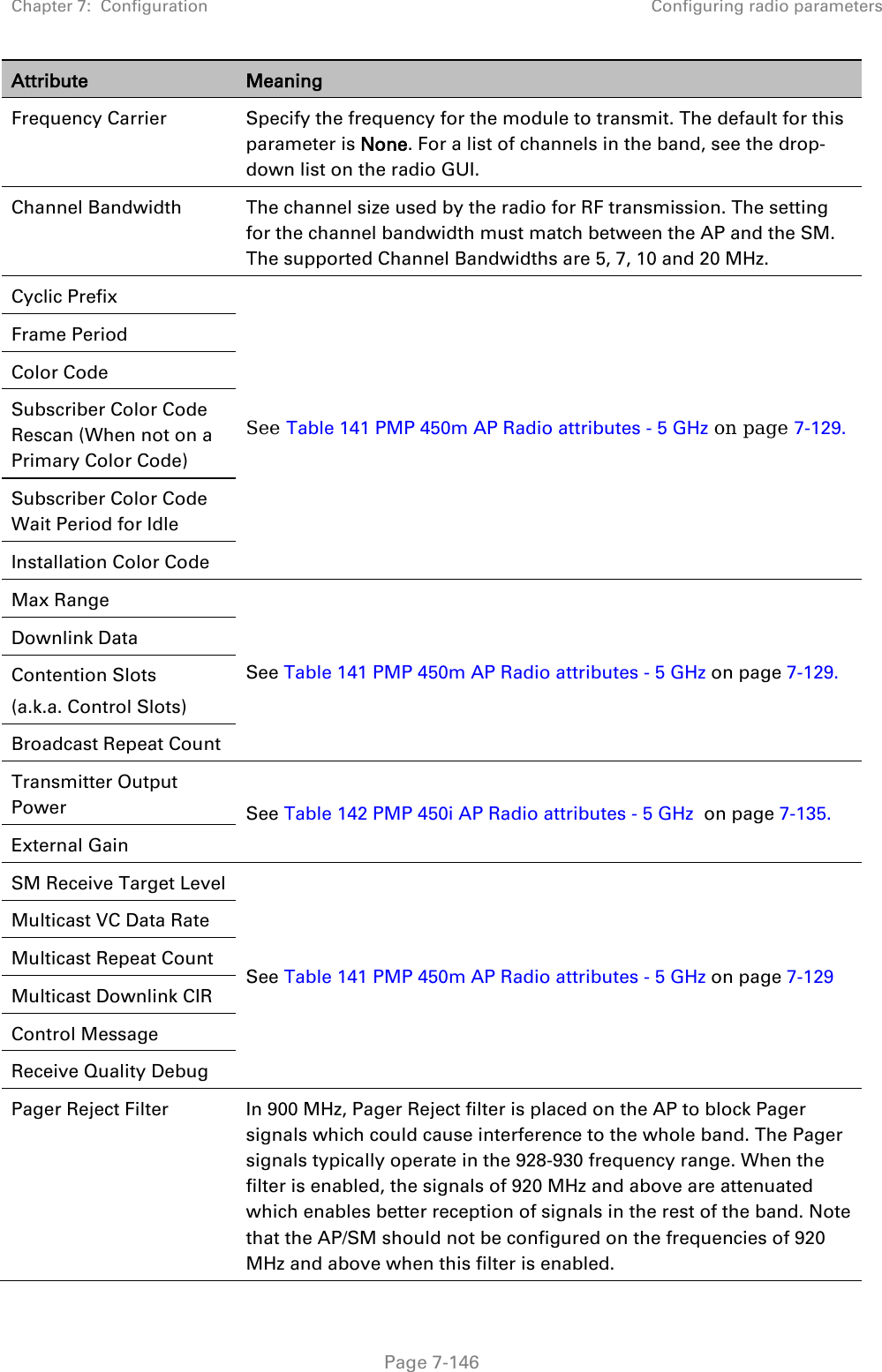
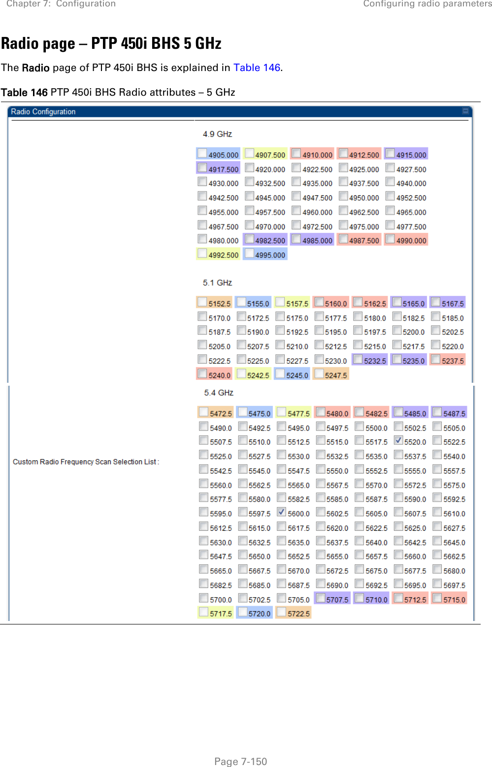
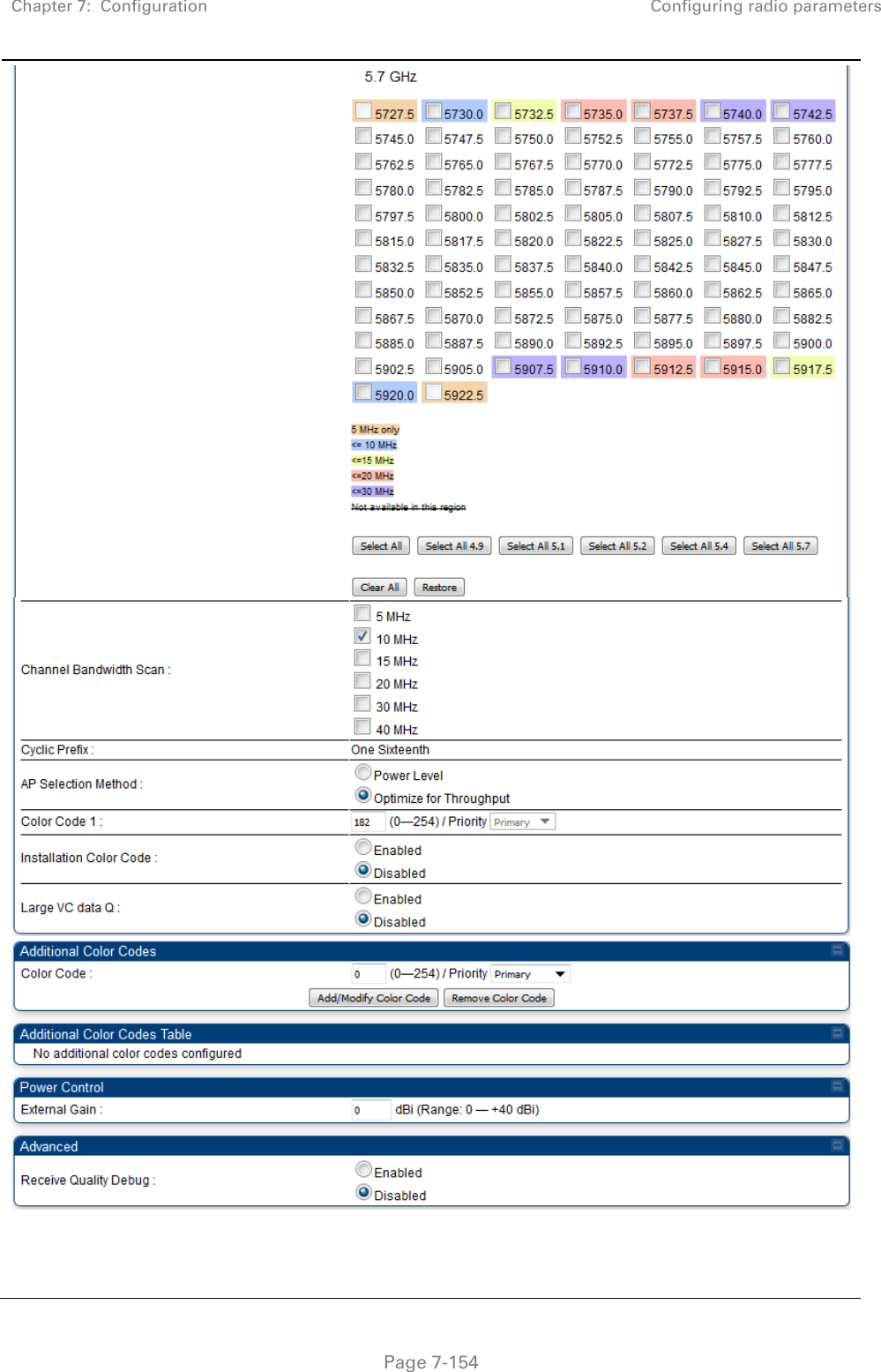


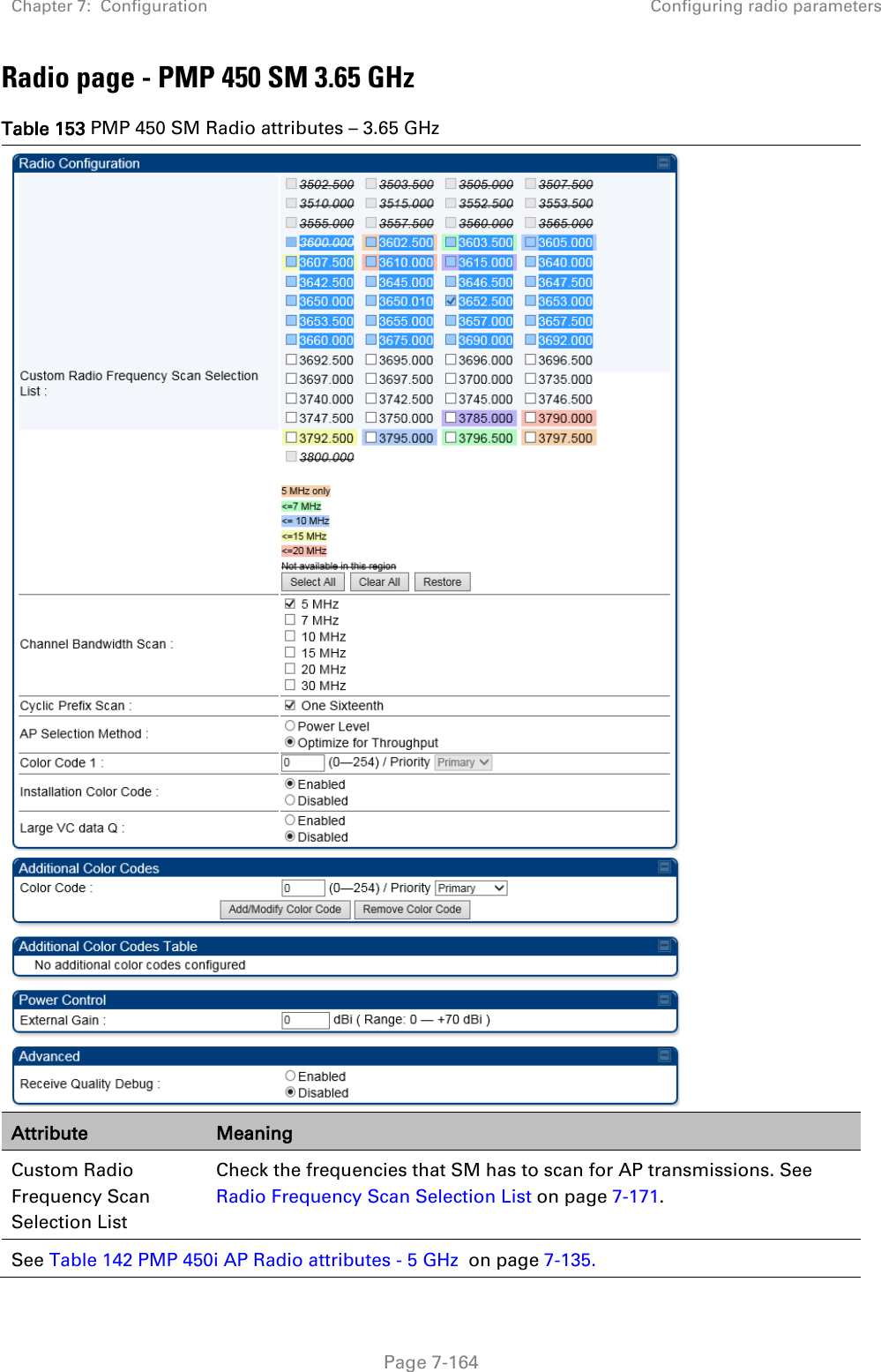
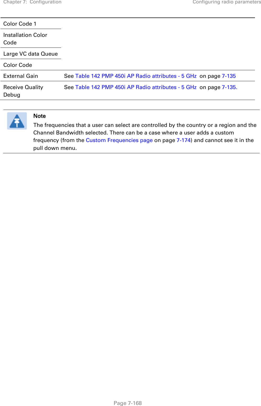
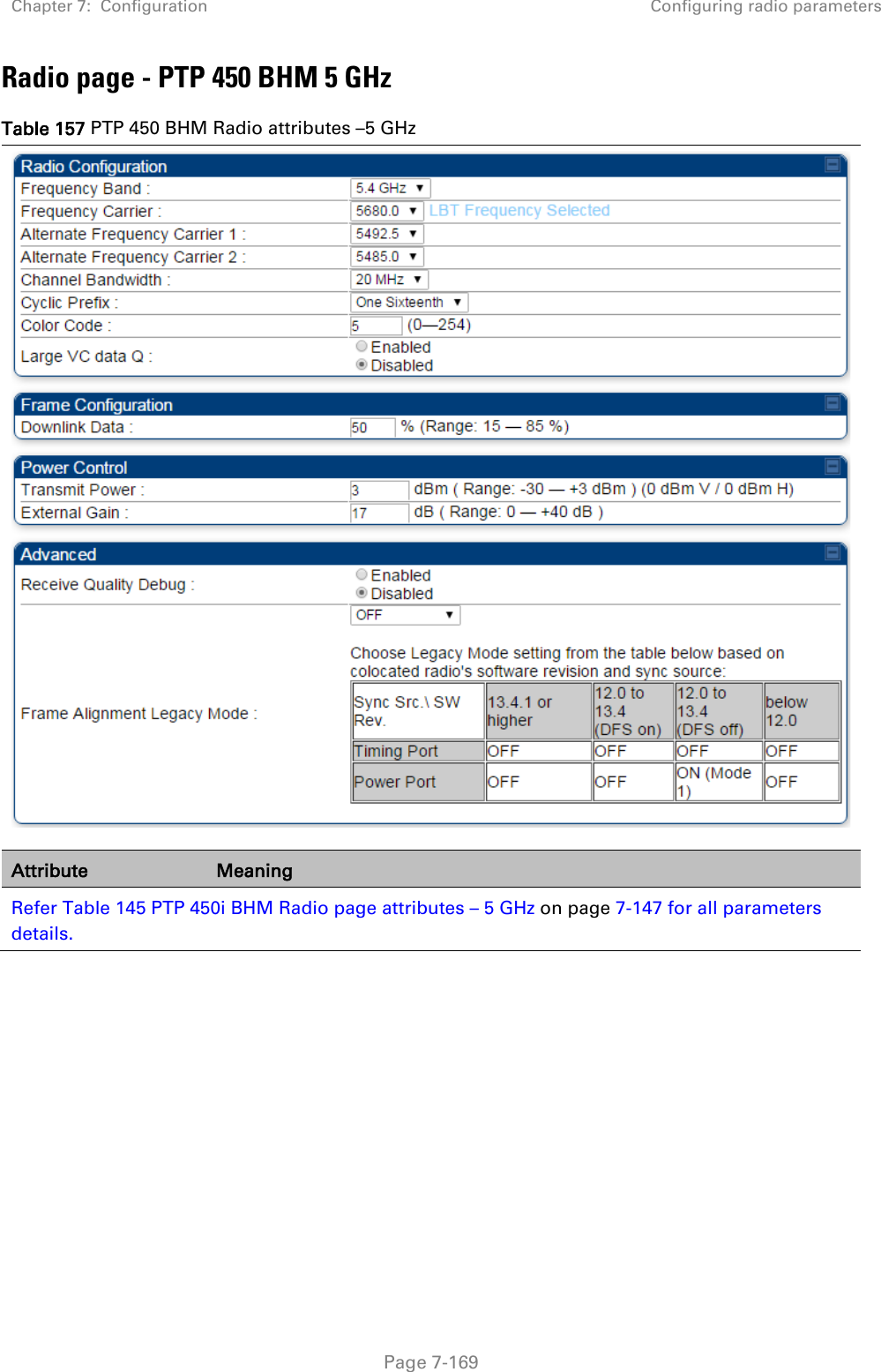
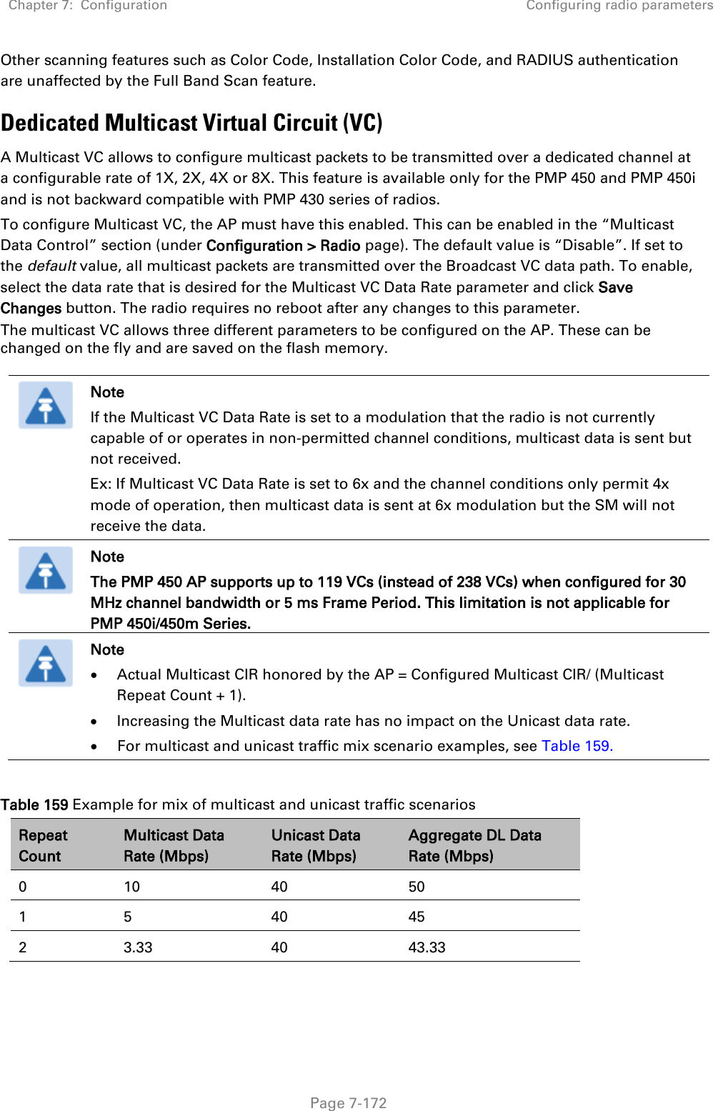
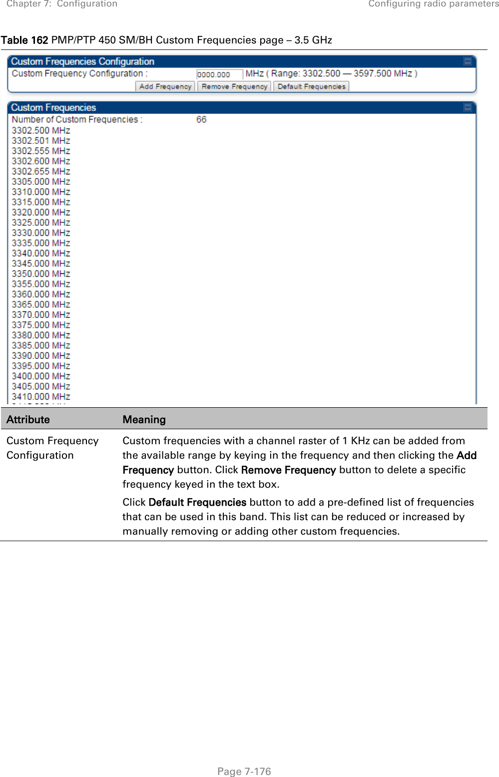
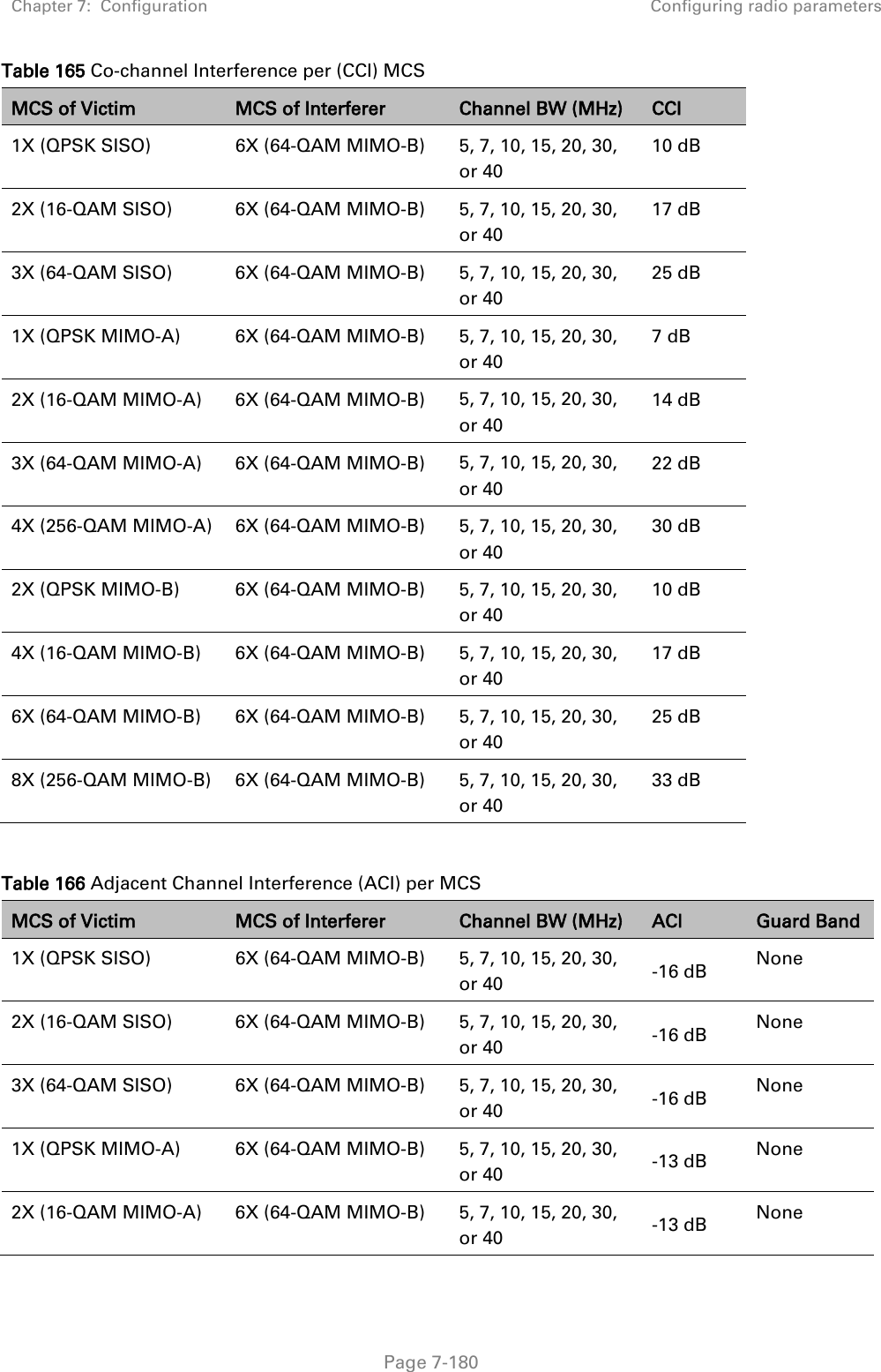
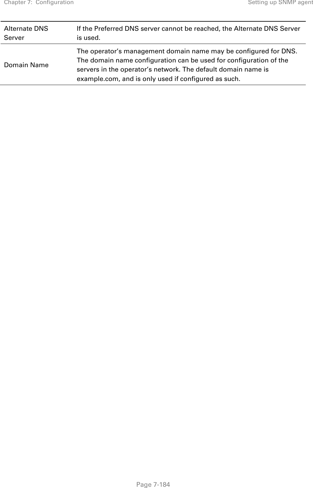
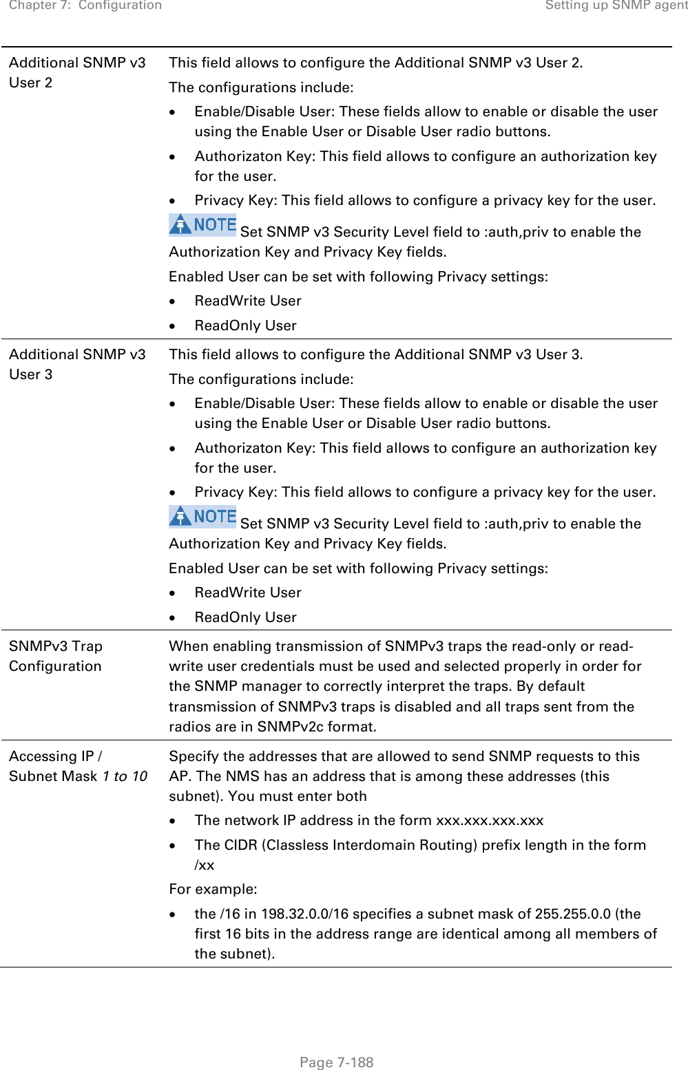
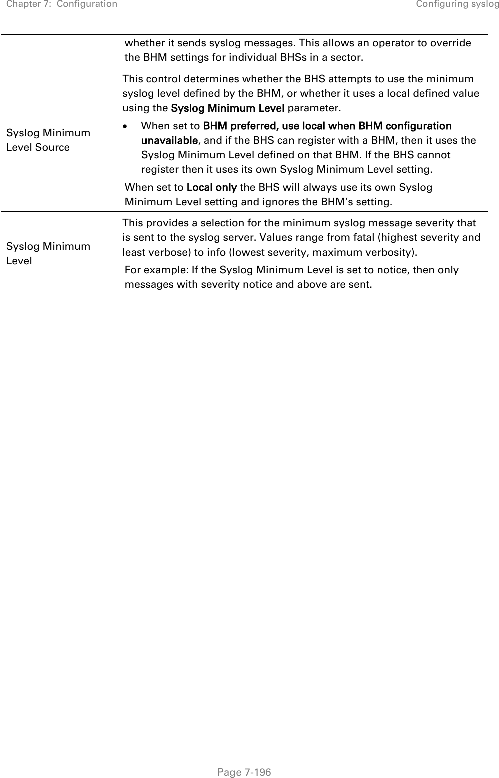
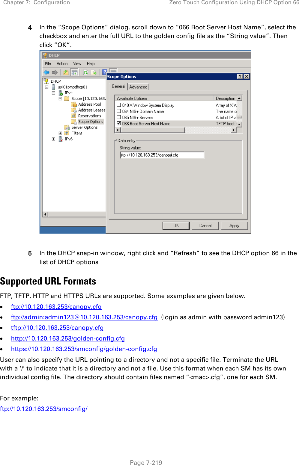
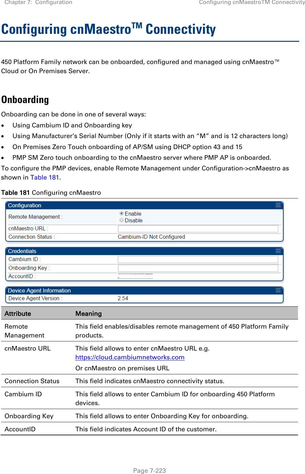
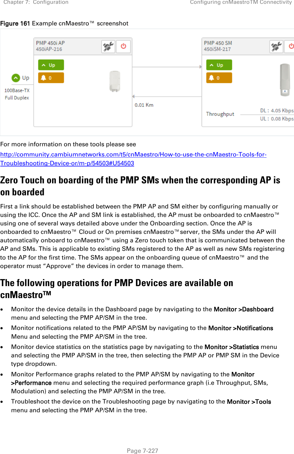
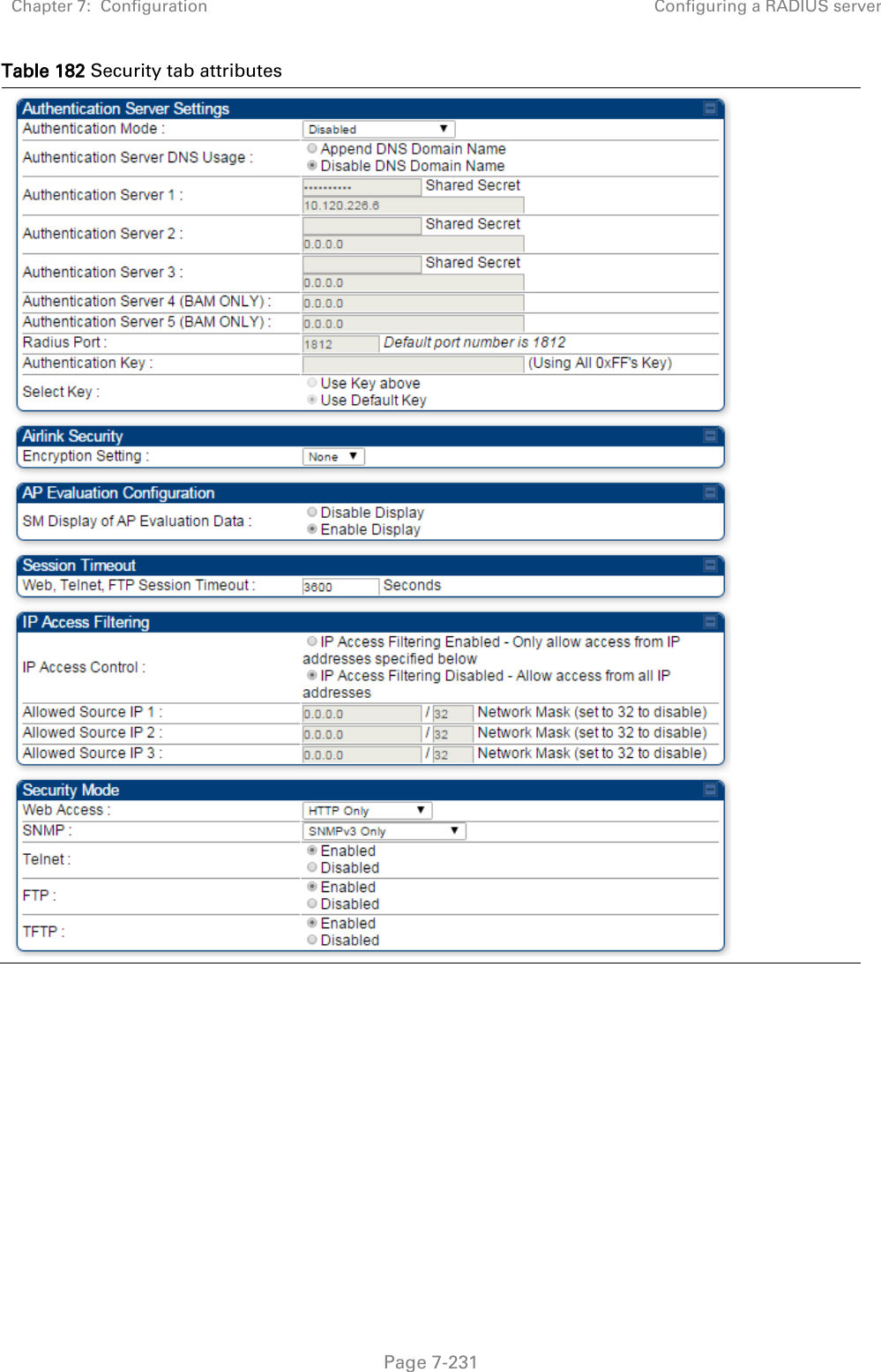
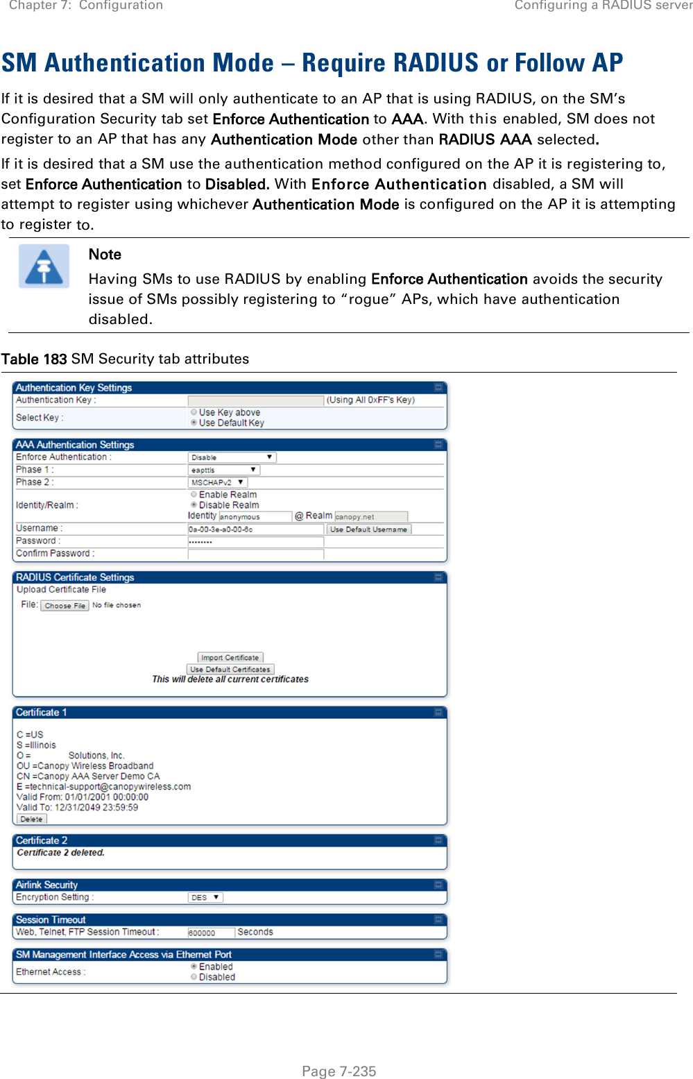
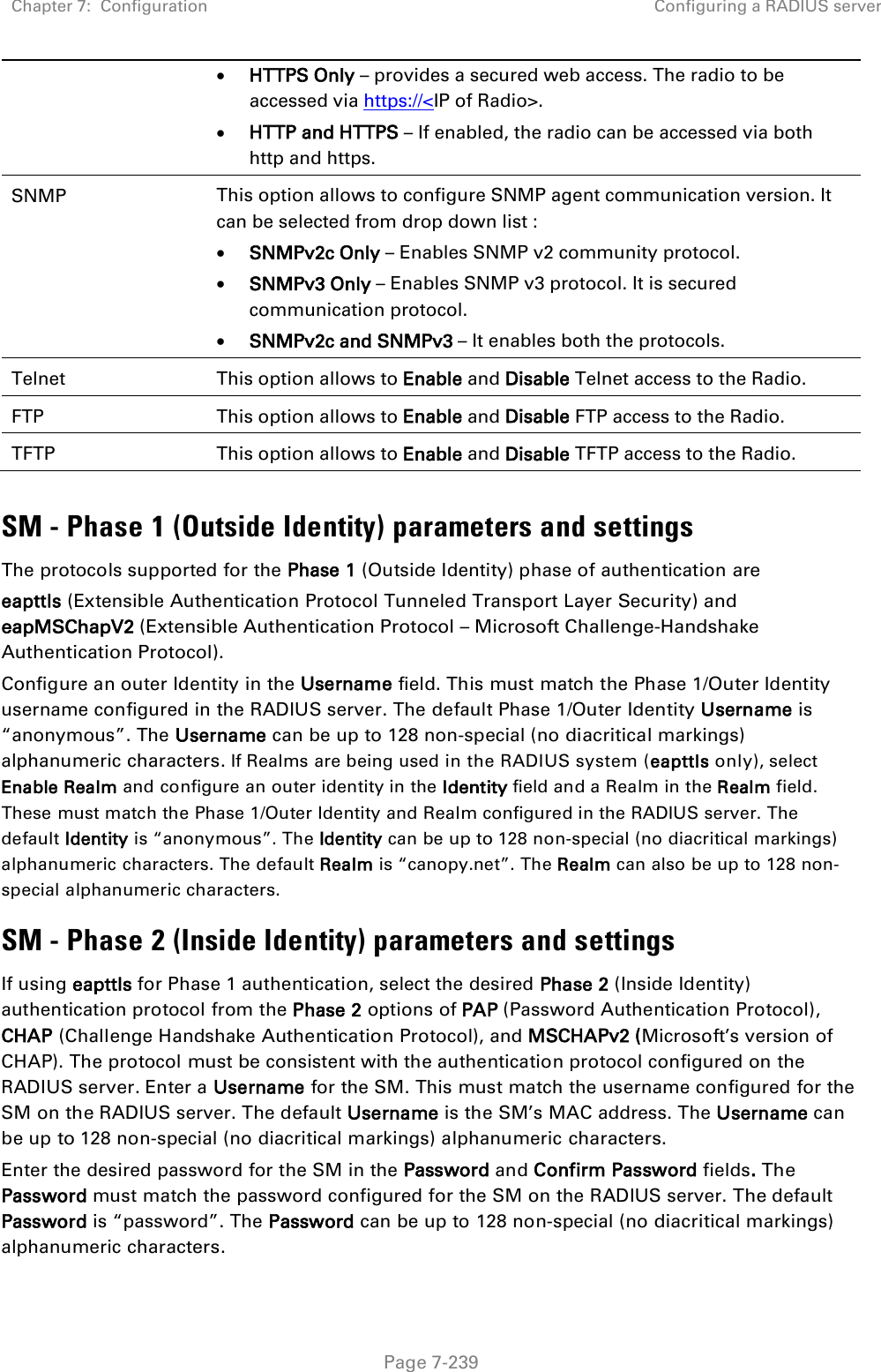
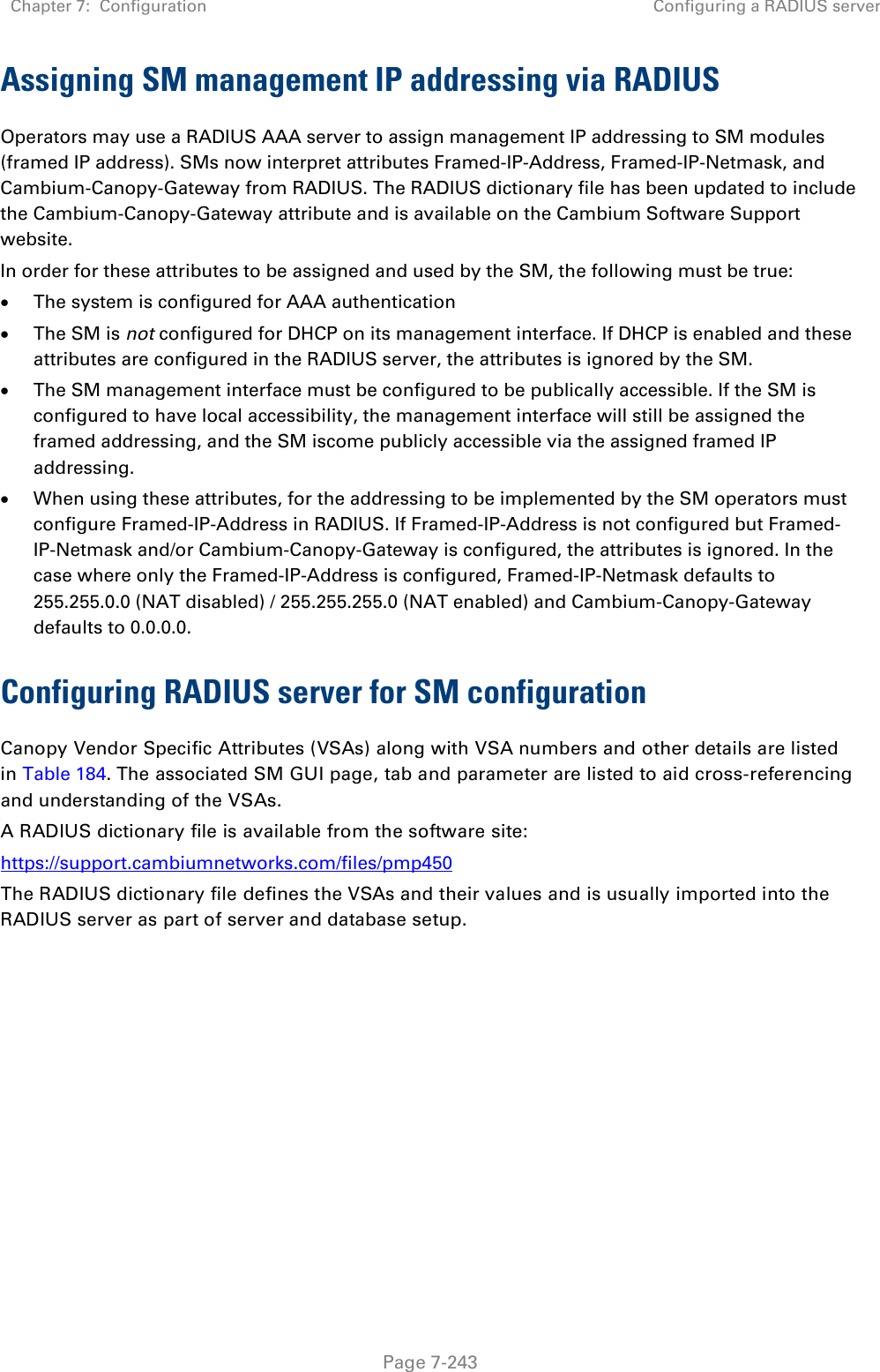
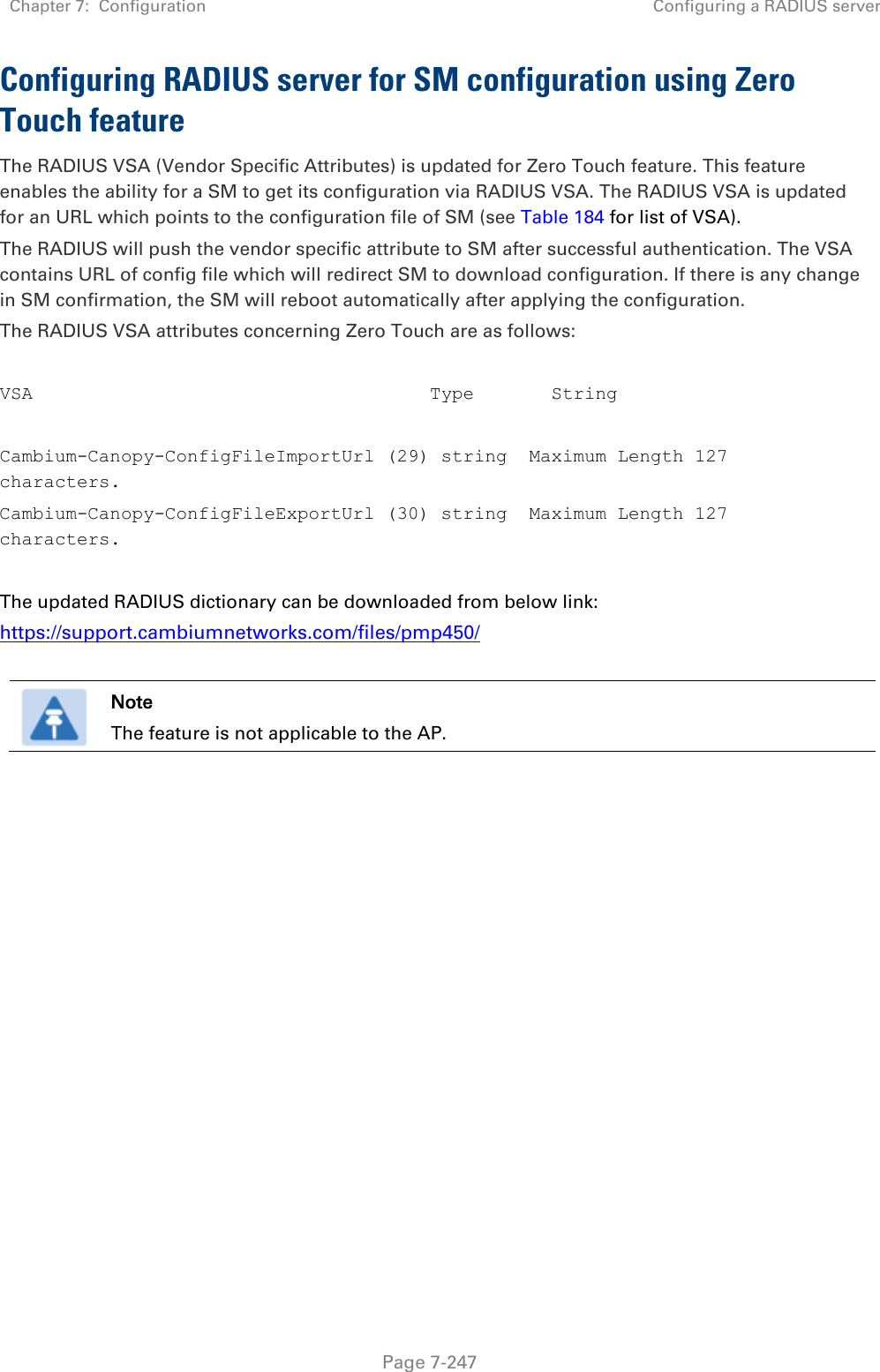
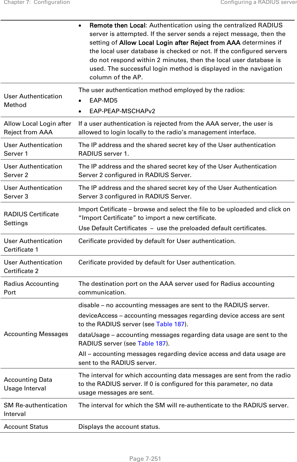
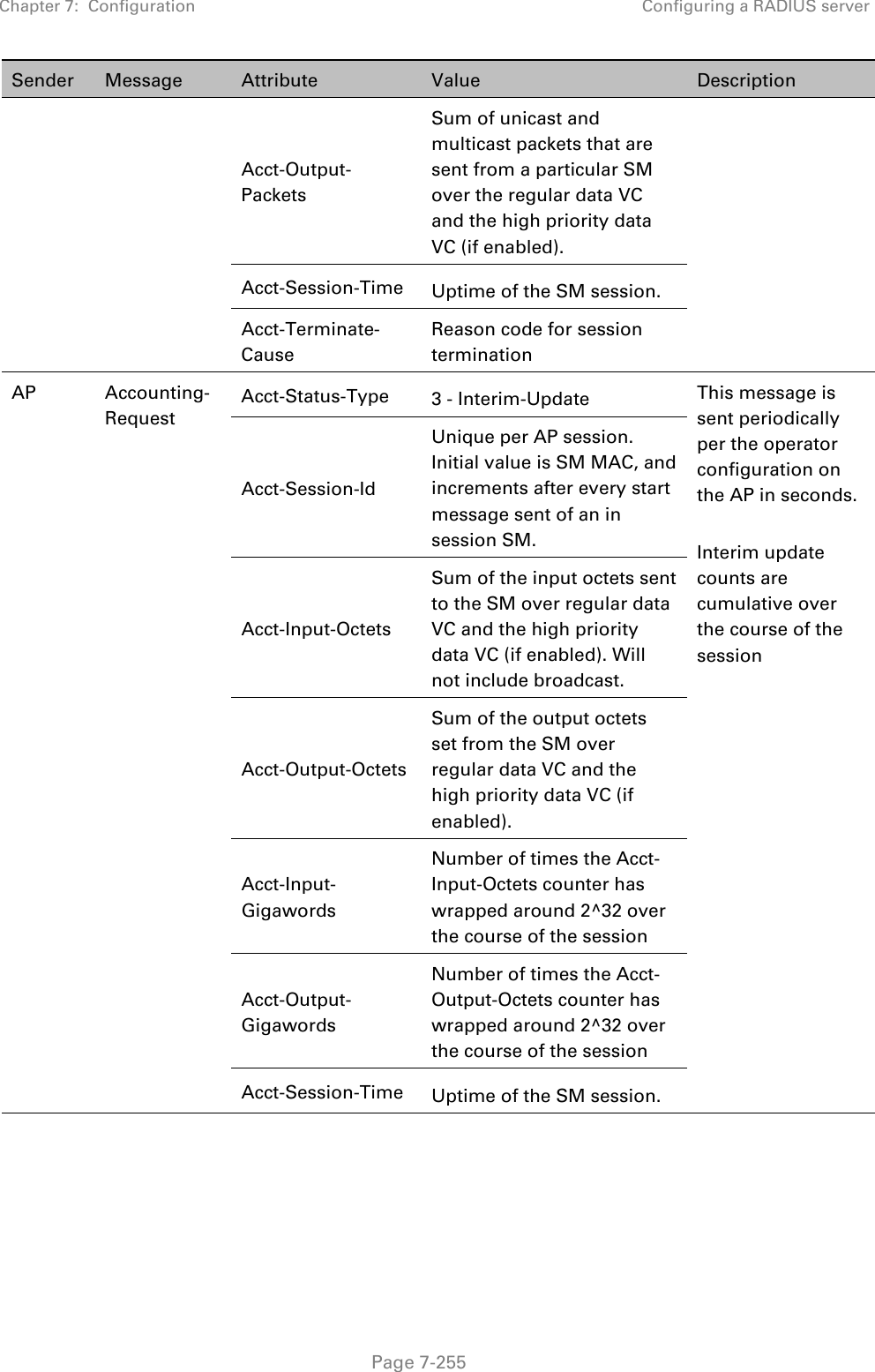
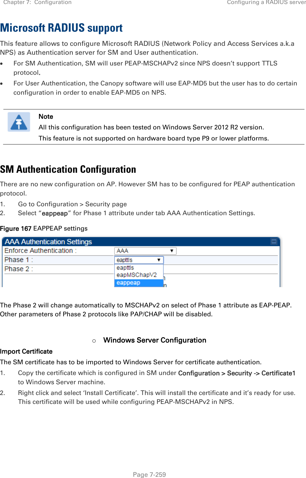
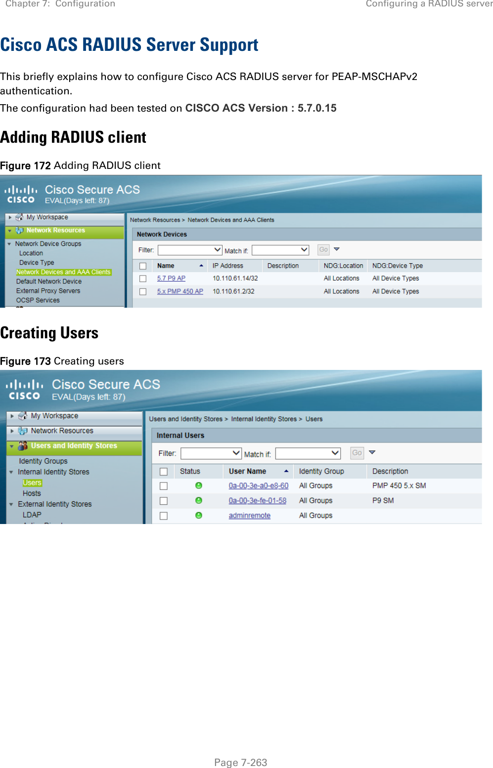
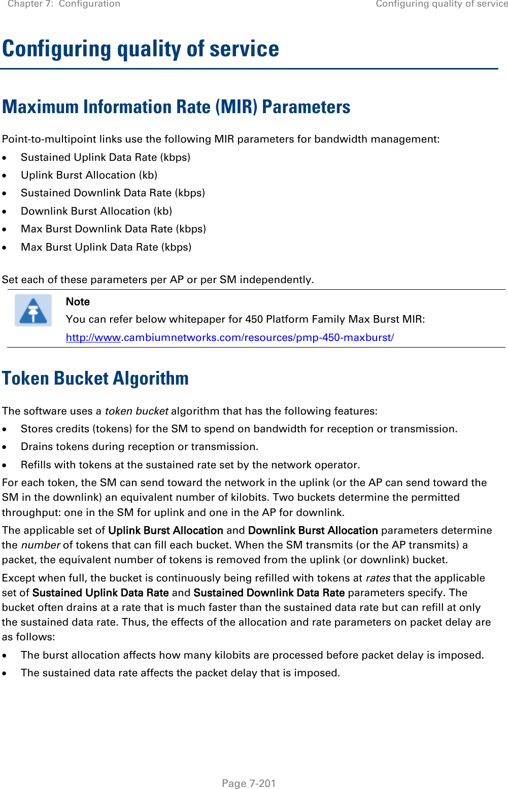
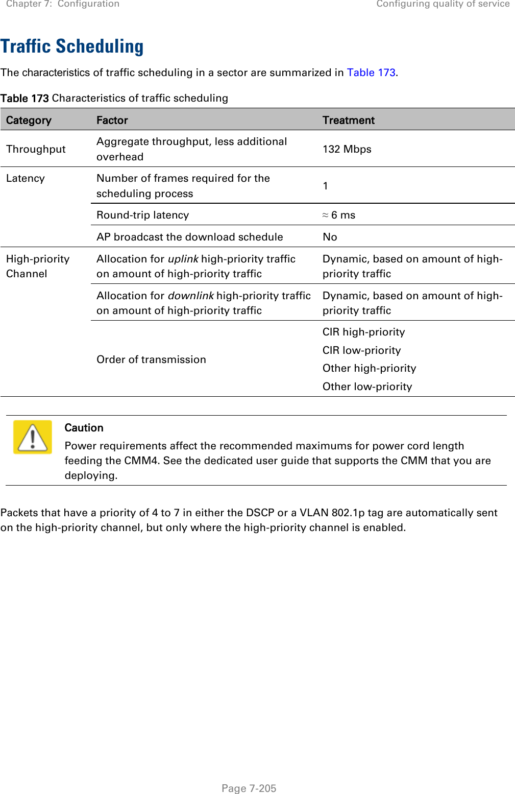
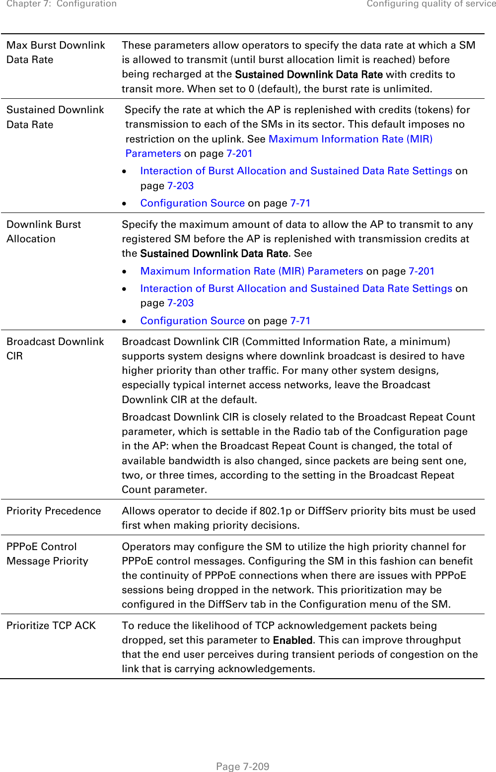
![Chapter 7: Configuration Configuring remote access Page 7-197 Configuring remote access Accessing SM/BHS over-the-air by Web Proxy The SM/BHS may be accessed via the AP/BHM management GUI by navigating to Home > Session Status (or Home > Remote Subscribers for AP only) and clicking on the SM’s hyperlink. For example, to access one of the SMs, click LUID: 002 – [0a-00-3e-37-b9-fd], as shown in Figure 150. Figure 150 AP Session Status page The SessionStatus.xml hyper link allows user to export all displayed SM data in Session Status table into an xml file. To access any one of the SMs, click 450 Platform Family - SM hyperlink, as shown in Figure 151. Figure 151 AP Remote Subscribers page](https://usermanual.wiki/Cambium-Networks/50450I.Users-Manual-Part-5/User-Guide-3815623-Page-88.png)
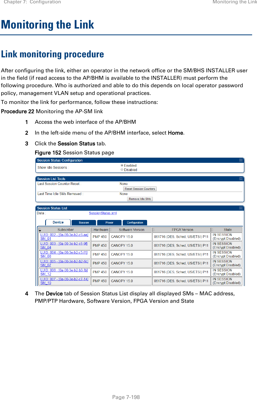
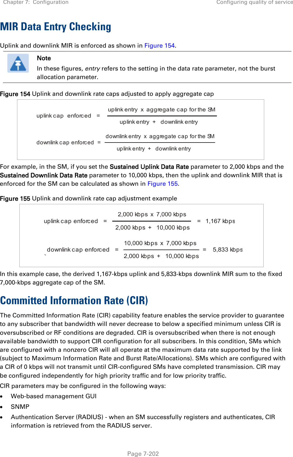
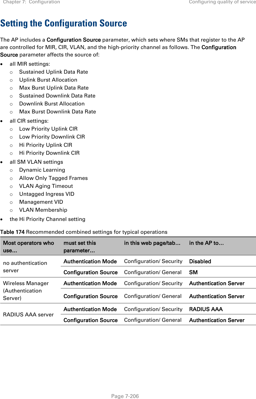
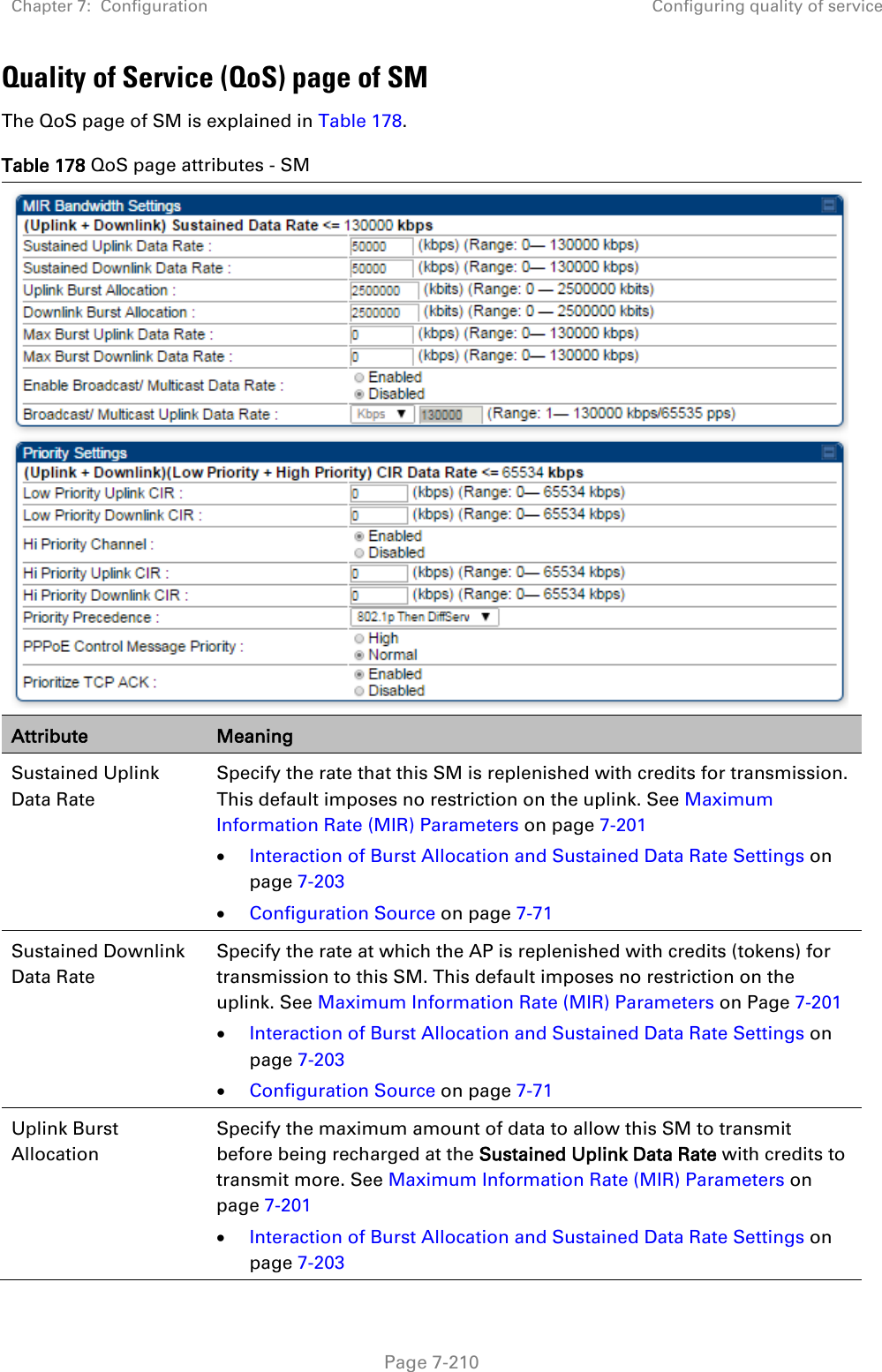
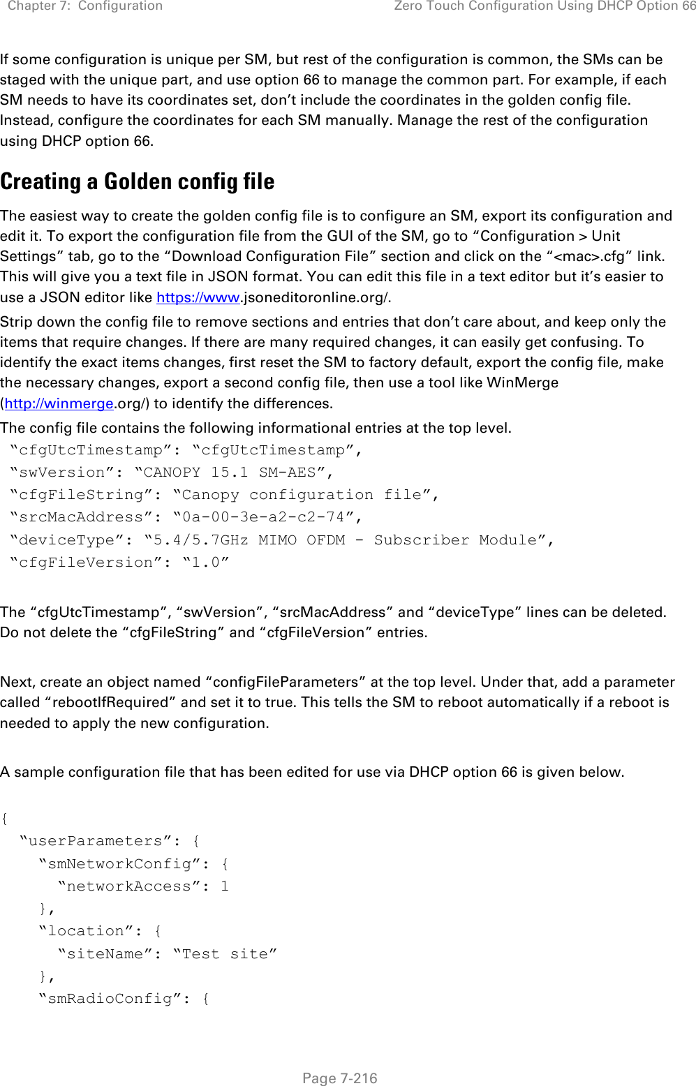
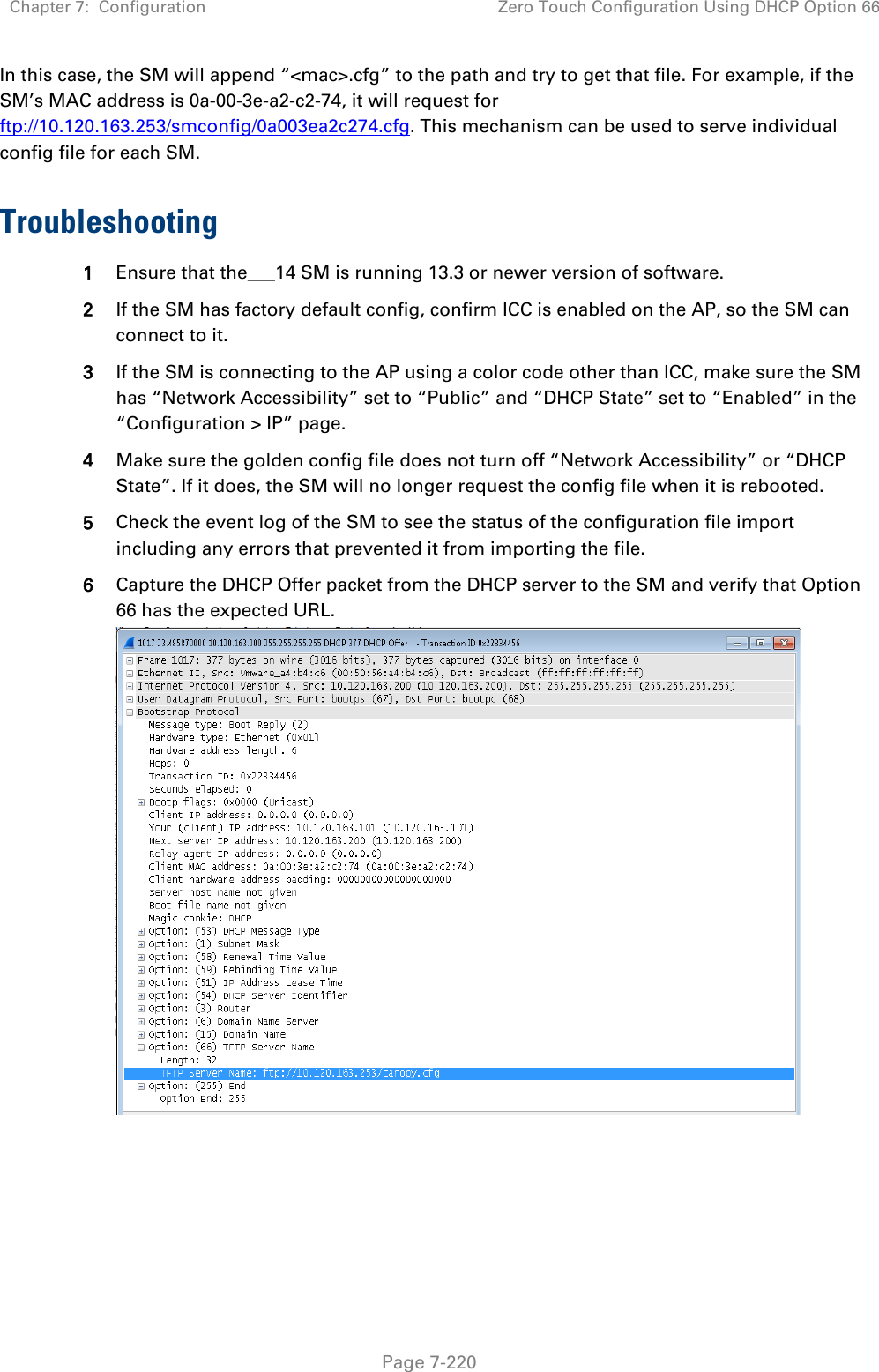
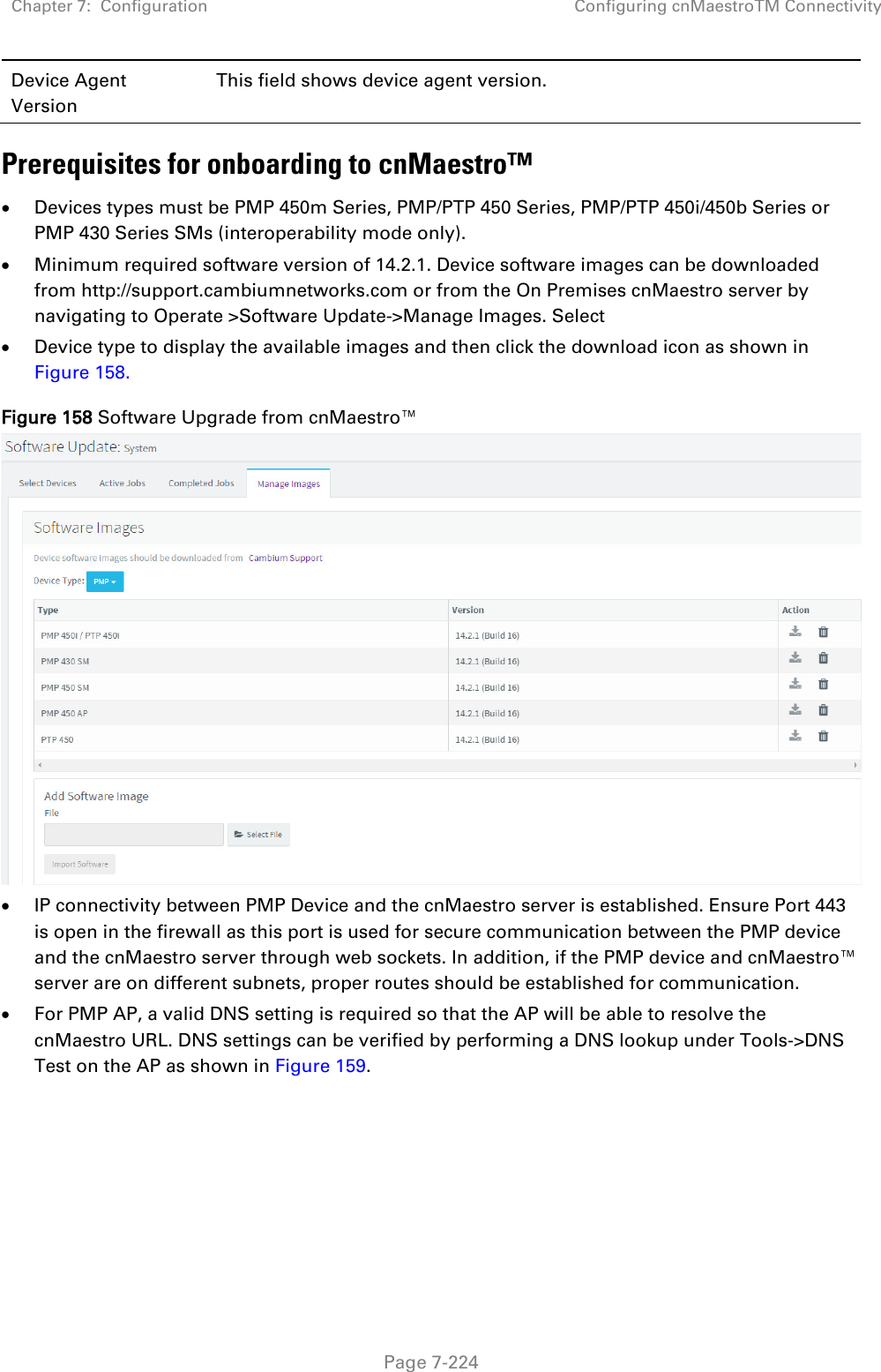
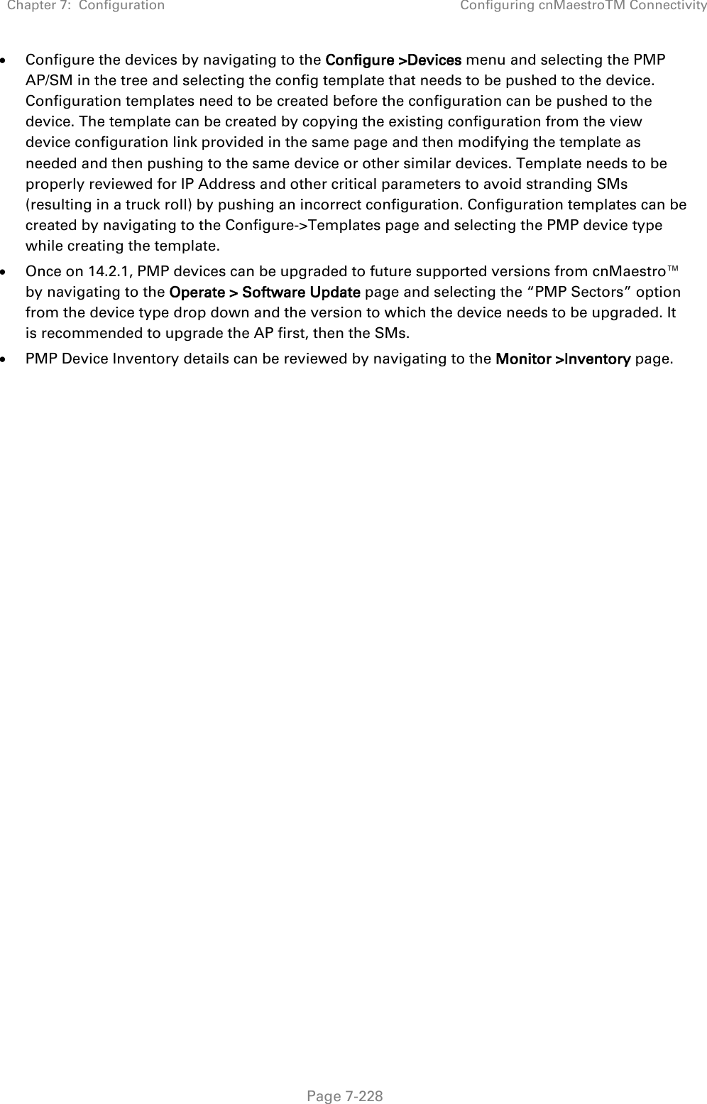
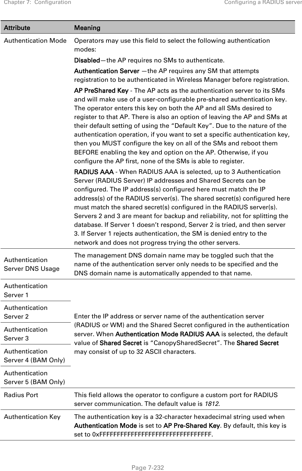
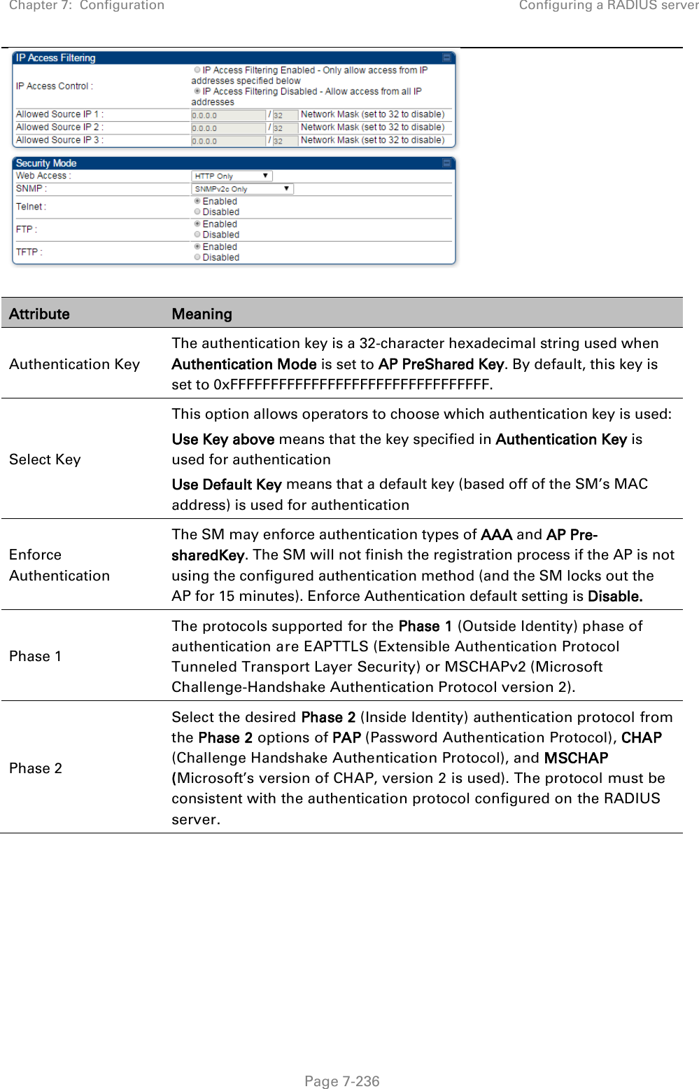
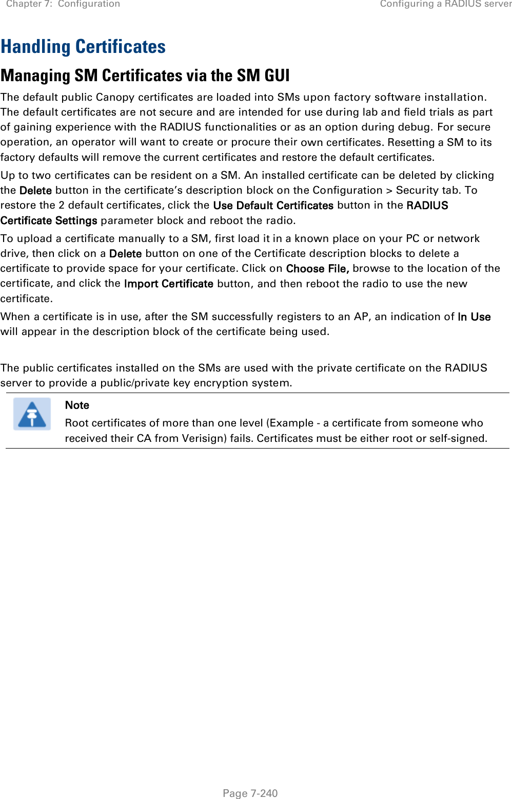
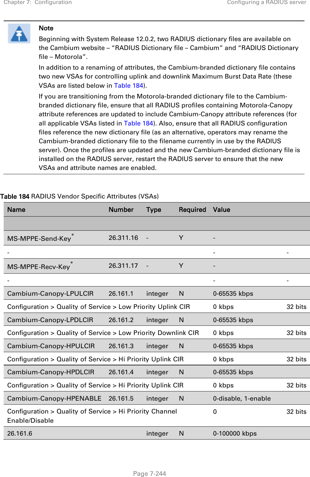
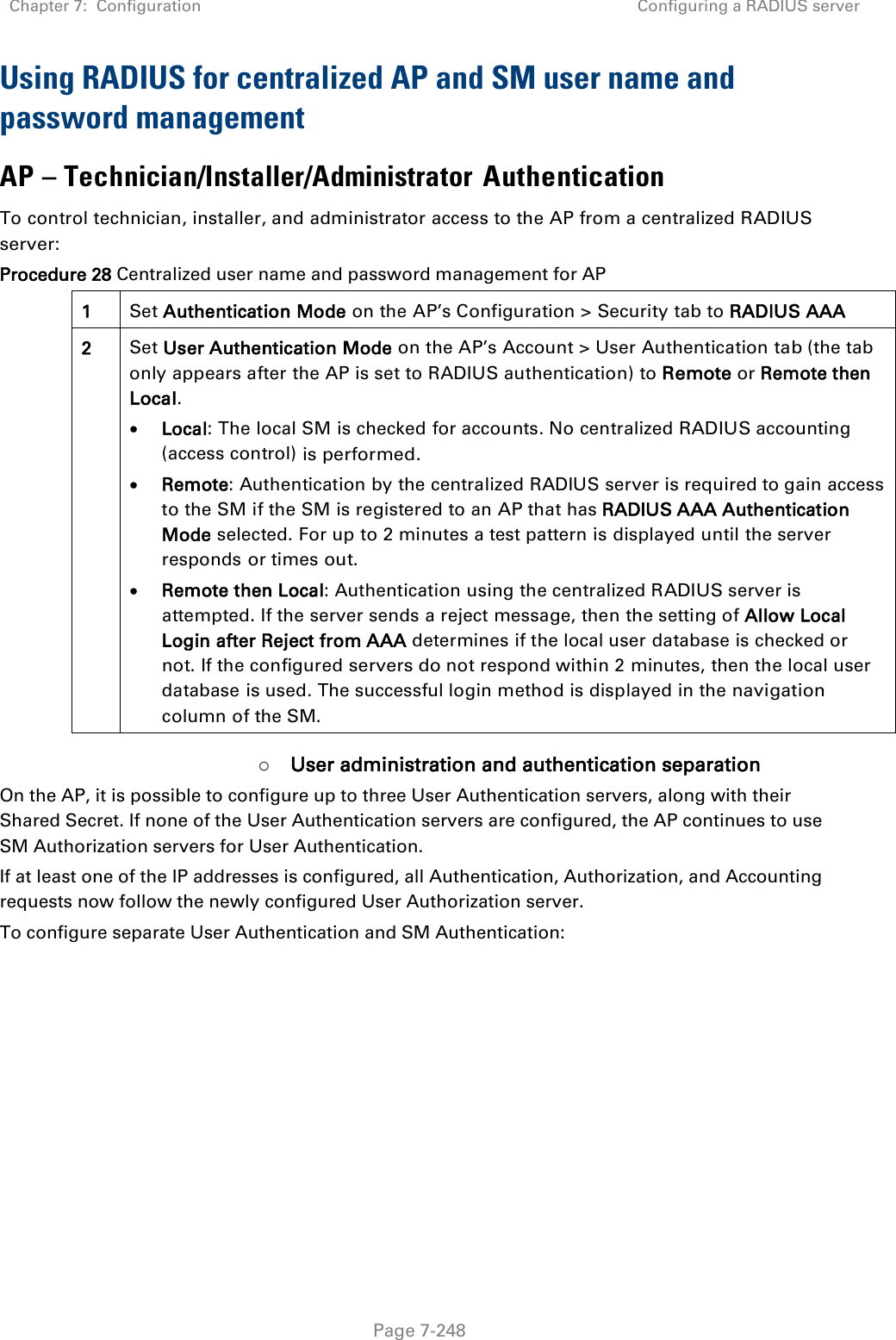
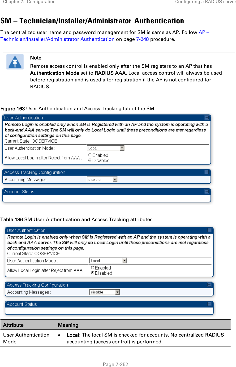
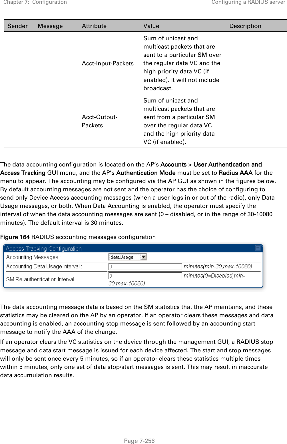
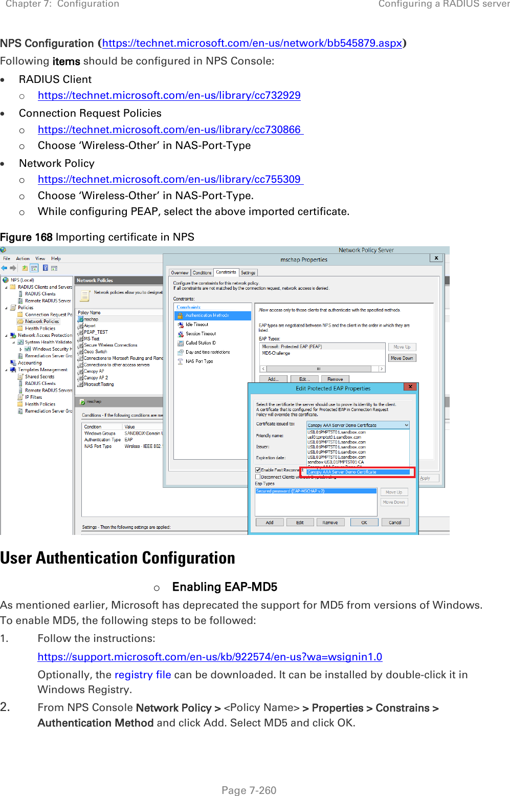
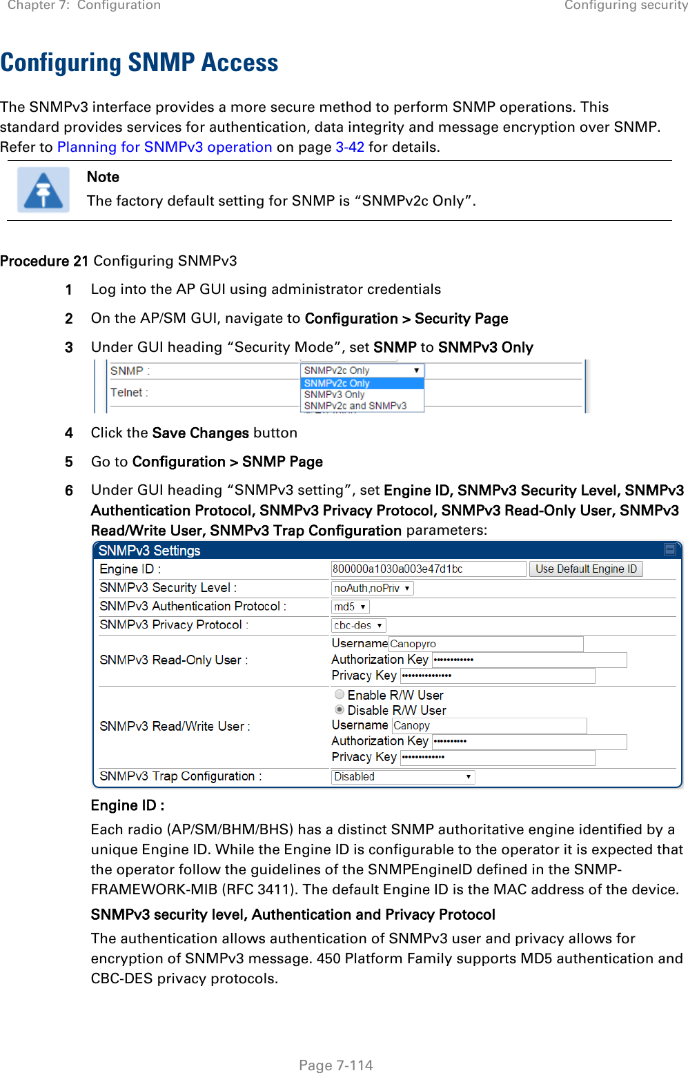
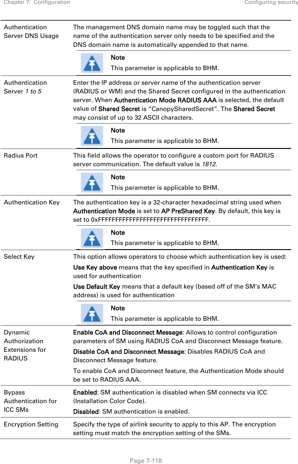
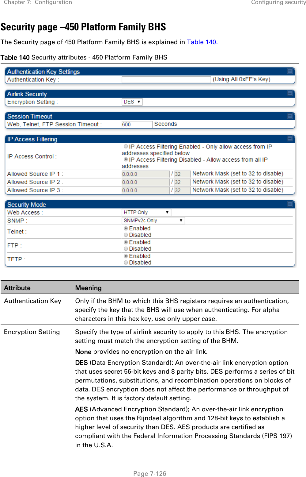
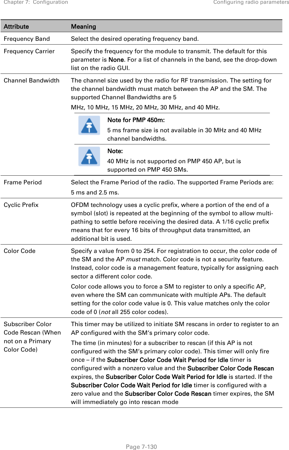
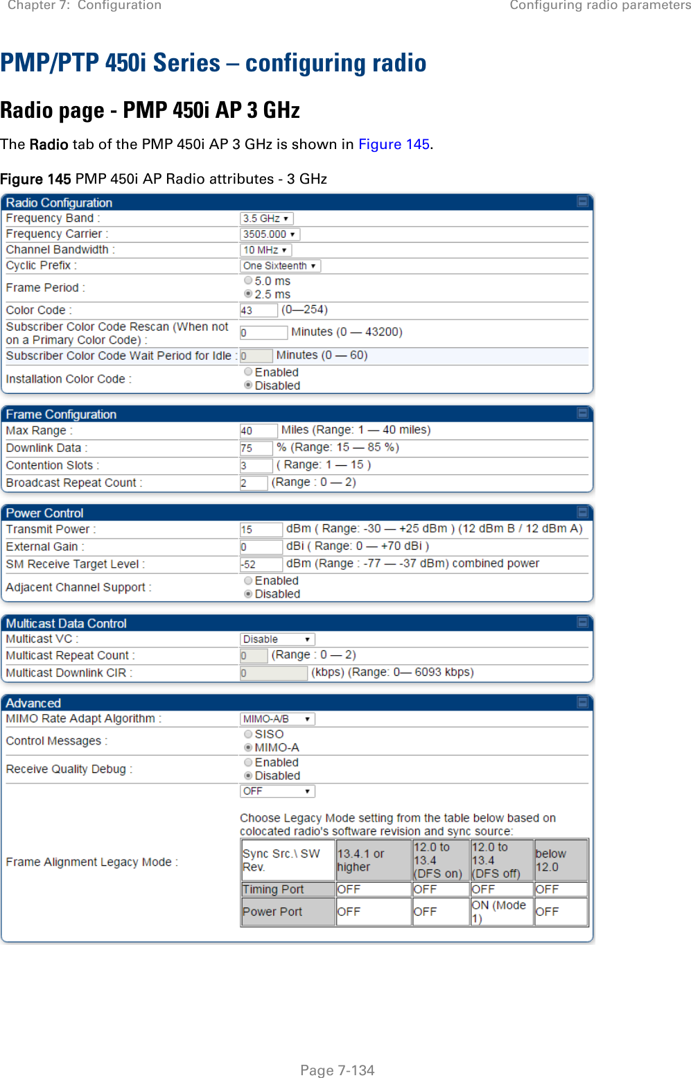
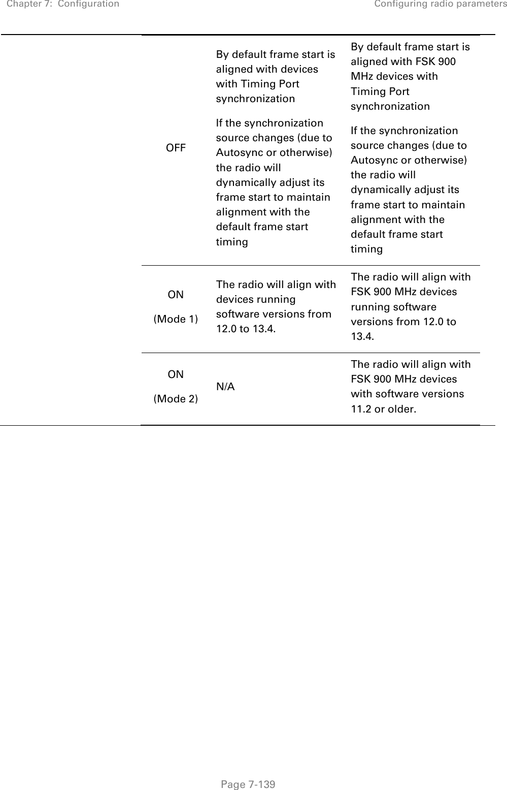
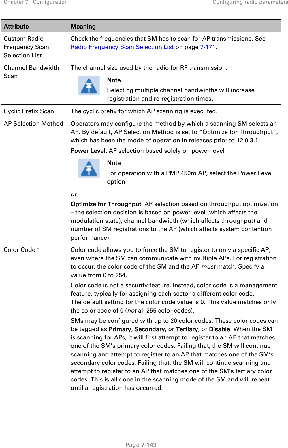
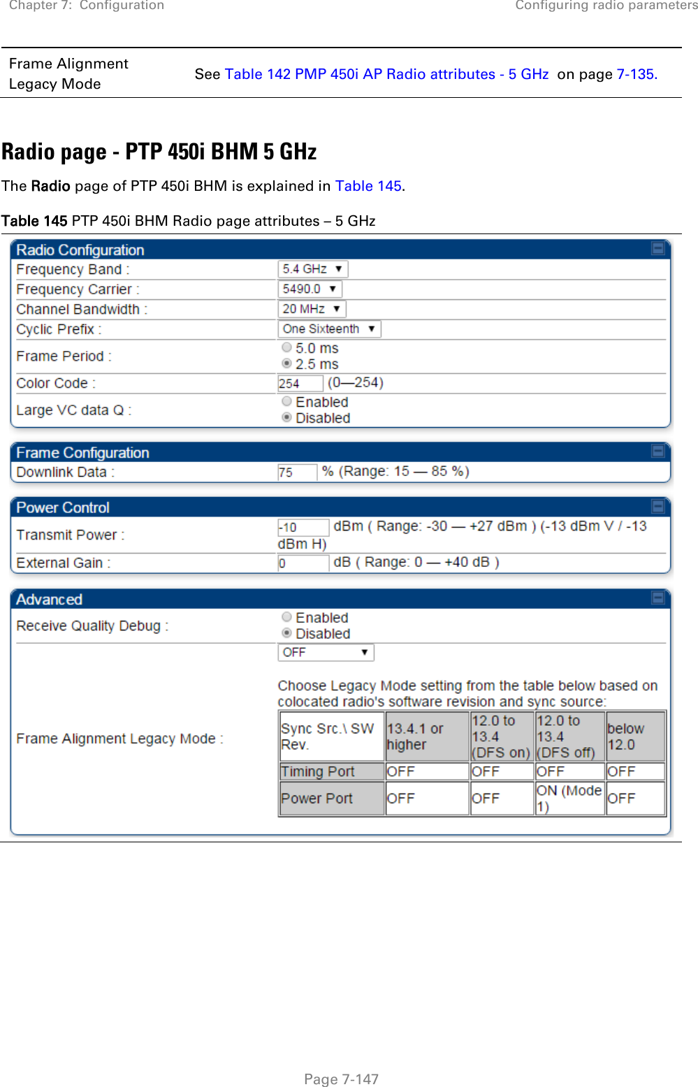
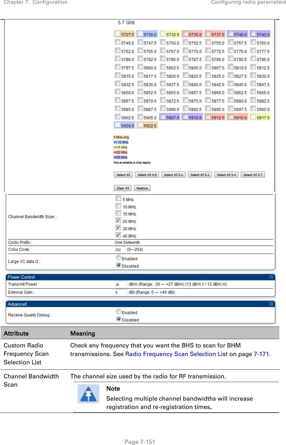
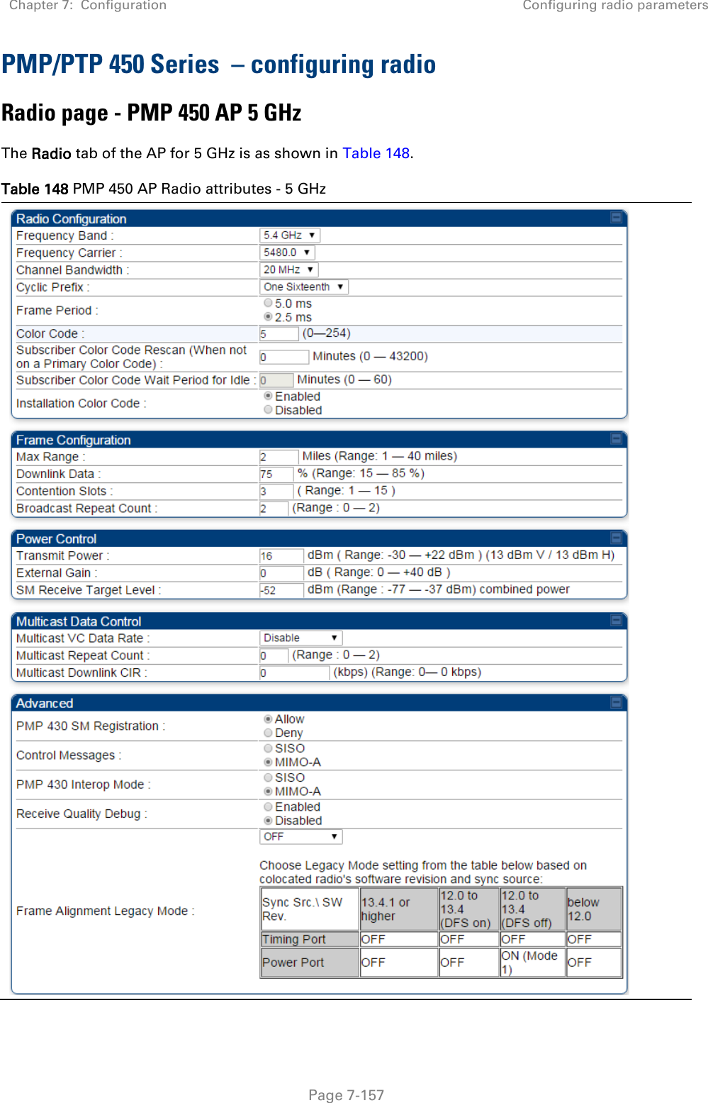
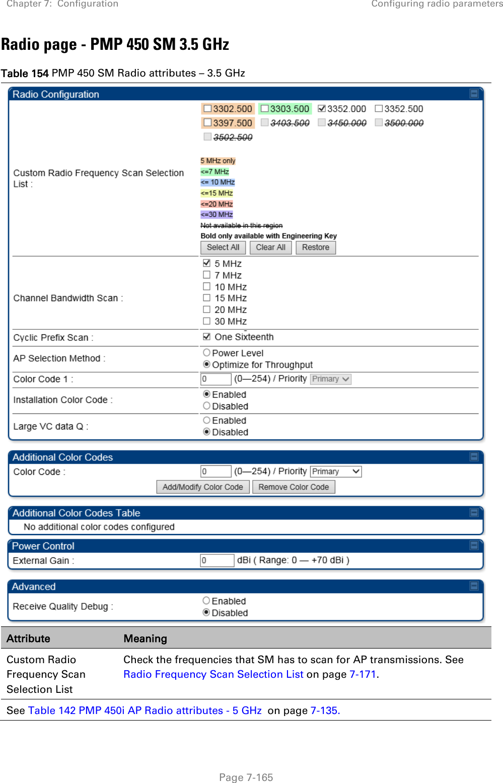
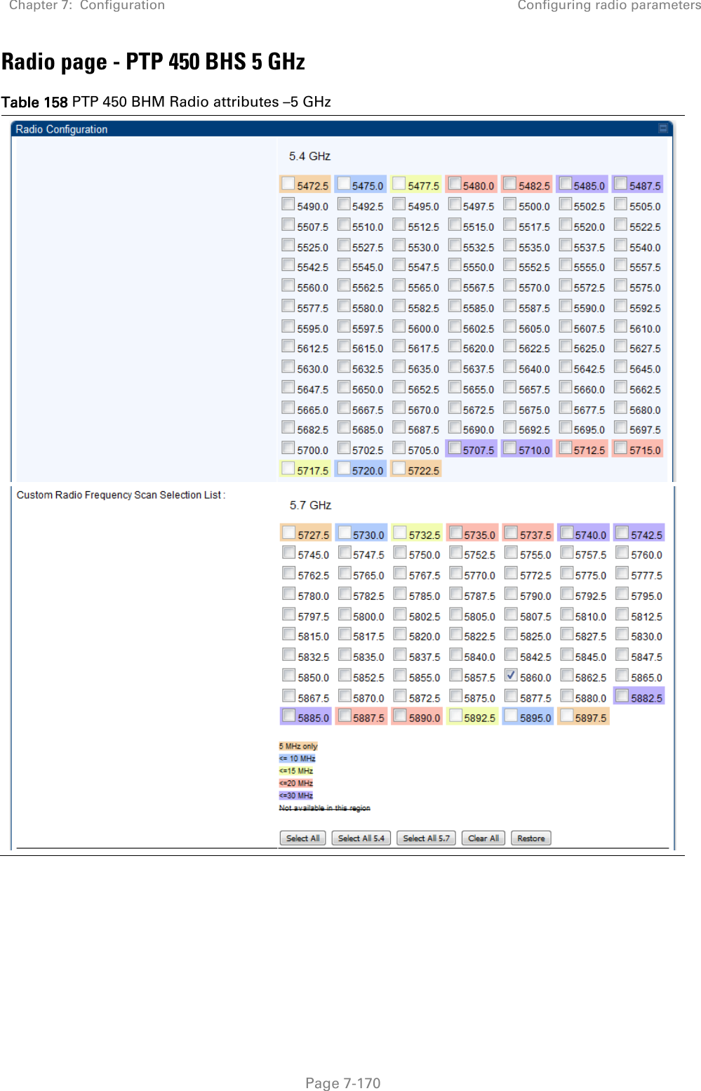
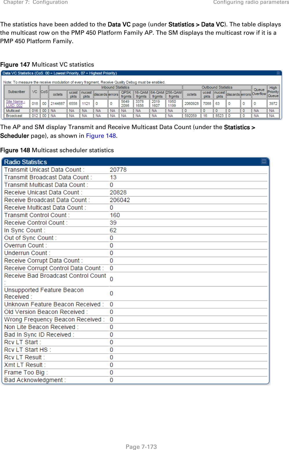
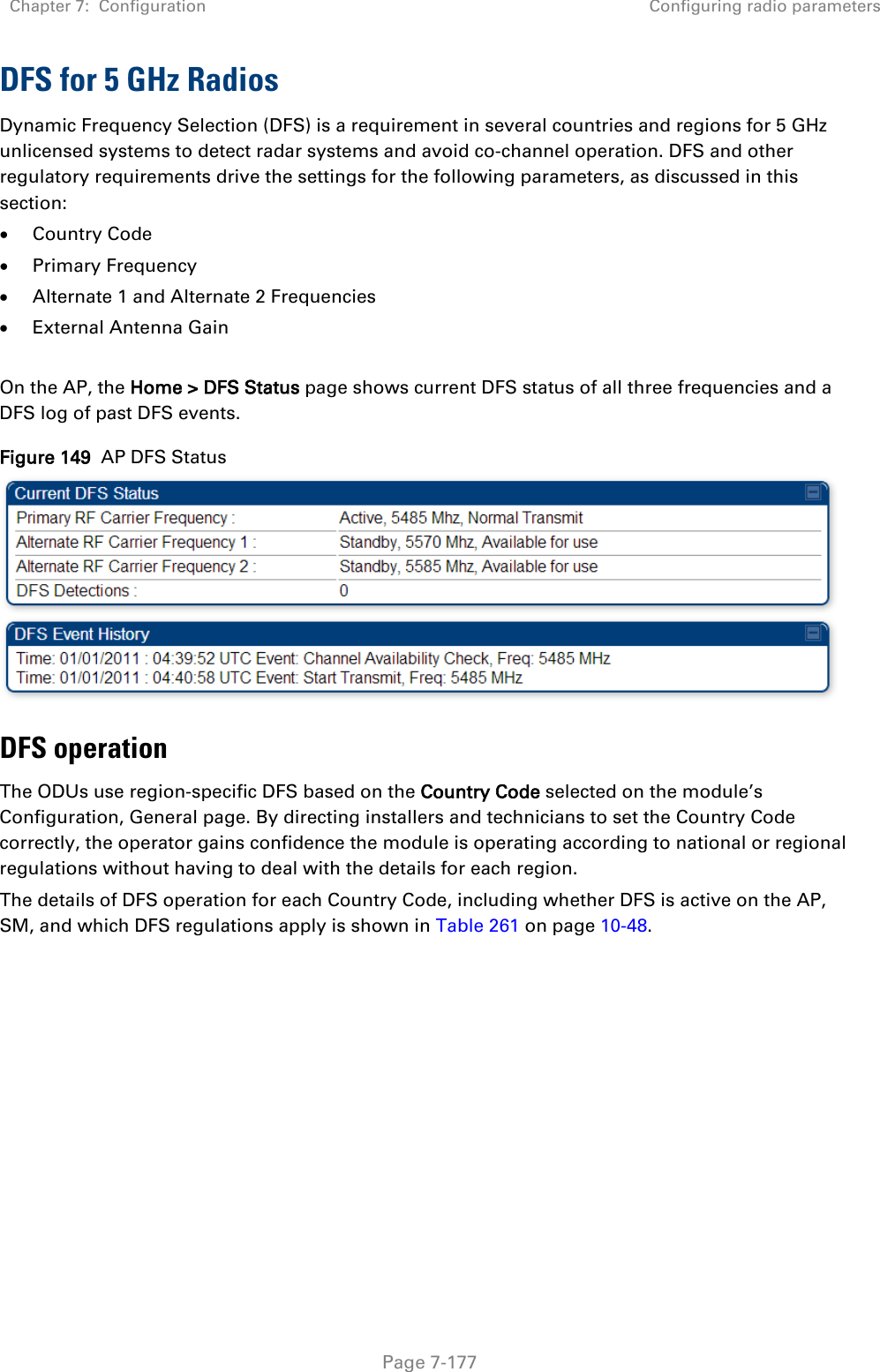
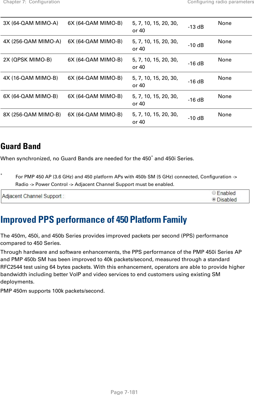
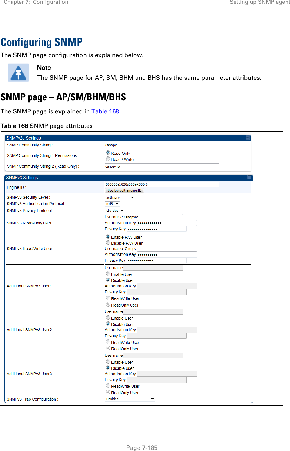
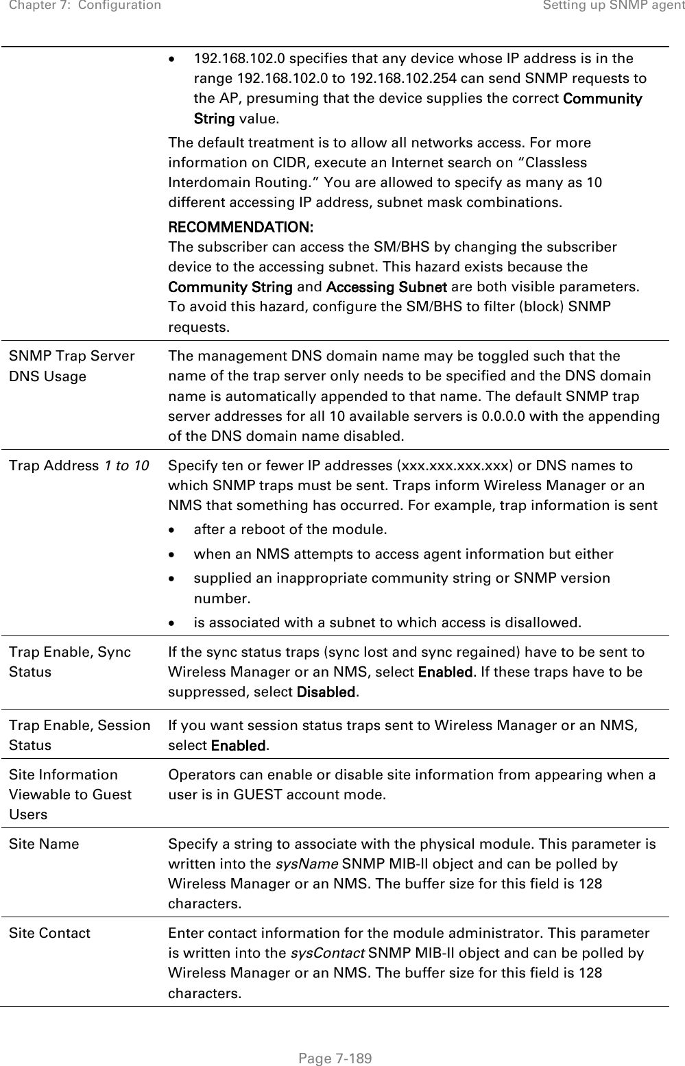
![Chapter 7: Configuration Zero Touch Configuration Using DHCP Option 66 Page 7-217 “frequencyScanList”: [ 5475000, 5480000 ], “colorCodeList”: [ { “colorCode”: 42, “priority”: 1 } ] }, “networkConfig”: { “lanDhcpState”: 1 } }, “cfgFileVersion”: “1.0”, “cfgFileString”: “Canopy configuration file”, “configFileParameters”: { “rebootIfRequired”: true } } When configuration is imported, only the items that exist in the configuration file are modified. Parameters that are not in the imported file are not changed. If user wish to revert those settings to their factory default values, please add a “setToDefaults” item under “configFileParameters” section with a value of true. “cfgFileVersion”: “1.0”, “cfgFileString”: “Canopy configuration file”, “configFileParameters”: { “rebootIfRequired”: true, “setToDefaults”: true } In case, the SM needs to fetch the configuration file on each boot up even when not connecting to AP via ICC, set “Network Accessibility” to “Public” and “DHCP State” to “Enabled” in the “Configuration > IP” page before exporting the configuration. Hosting the config file Copy the golden configuration file to an FTP, TFTP, HTTP or HTTPS server. This location can be password protected; you just have to include the user name and password in the URL. DHCP server configuration Configure DHCP server to return the full URL to the golden config file as the value of DHCP option 66.](https://usermanual.wiki/Cambium-Networks/50450I.Users-Manual-Part-5/User-Guide-3815623-Page-108.png)