Cambium Networks 50450I Wireless Ethernet Bridge, Dual Channel OFDM MIMO Combination Access Point, Subscriber Station and Point to Point Equipment User Manual PMP 450i and PTP 450i Configuration and User Guide
Cambium Networks Limited Wireless Ethernet Bridge, Dual Channel OFDM MIMO Combination Access Point, Subscriber Station and Point to Point Equipment PMP 450i and PTP 450i Configuration and User Guide
Contents
- 1. Installation Guide
- 2. User Guide Part 1
- 3. User Guide Part 2
- 4. User Guide Part 3
- 5. User Guide Part 4
- 6. User Guide Part 5
- 7. User Guide Part 6
- 8. User Guide Part 7
- 9. Exhibit D Users Manual per 2 1033 b3
- 10. User Manual - Part 1
- 11. User Manual - Part 2
- 12. User Manual - Part 3
- 13. User Manual - Part 4
- 14. Users Manual - Part 5
- 15. Users Manual - Part 6
- 16. User Manual
Installation Guide

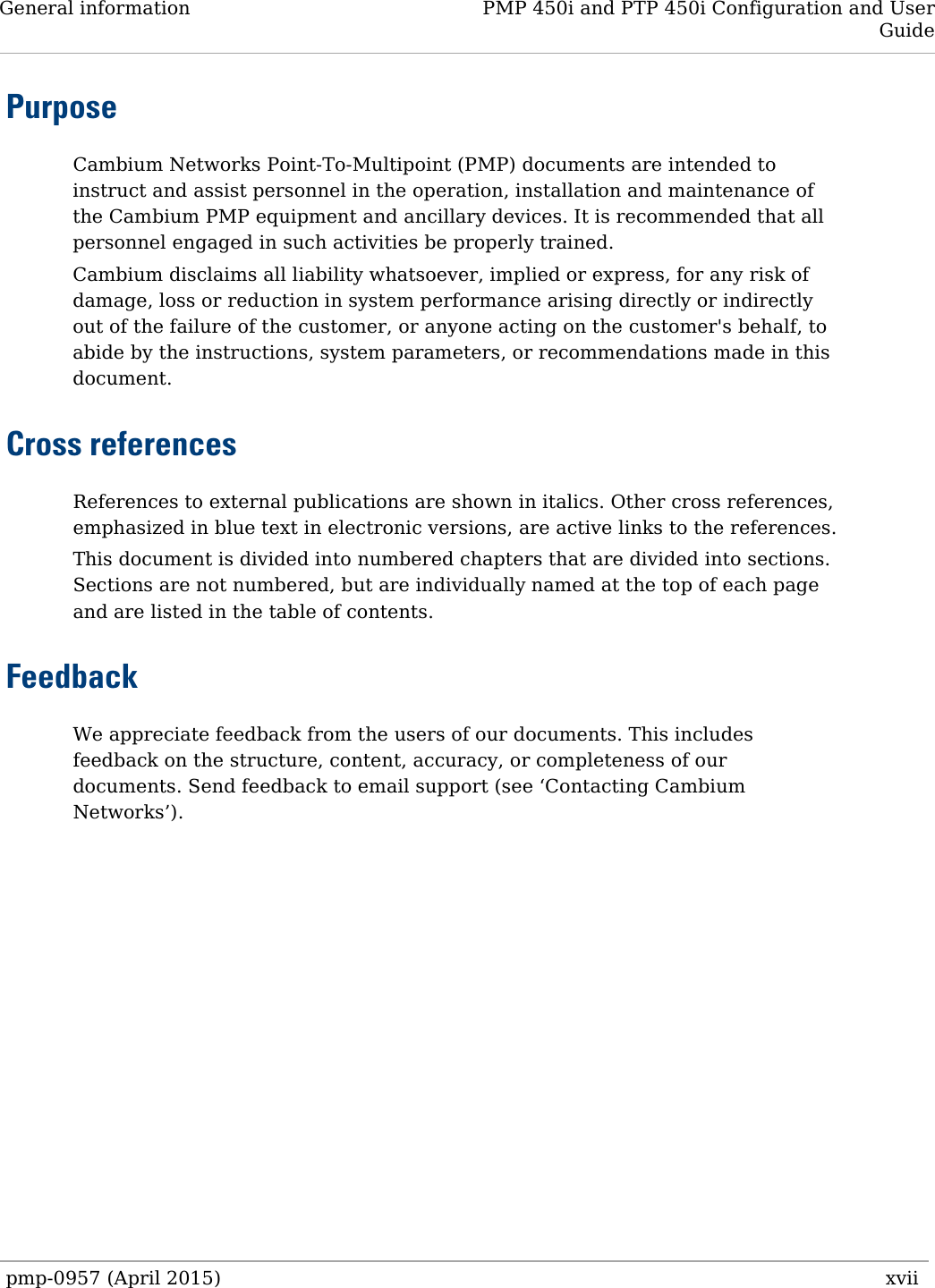
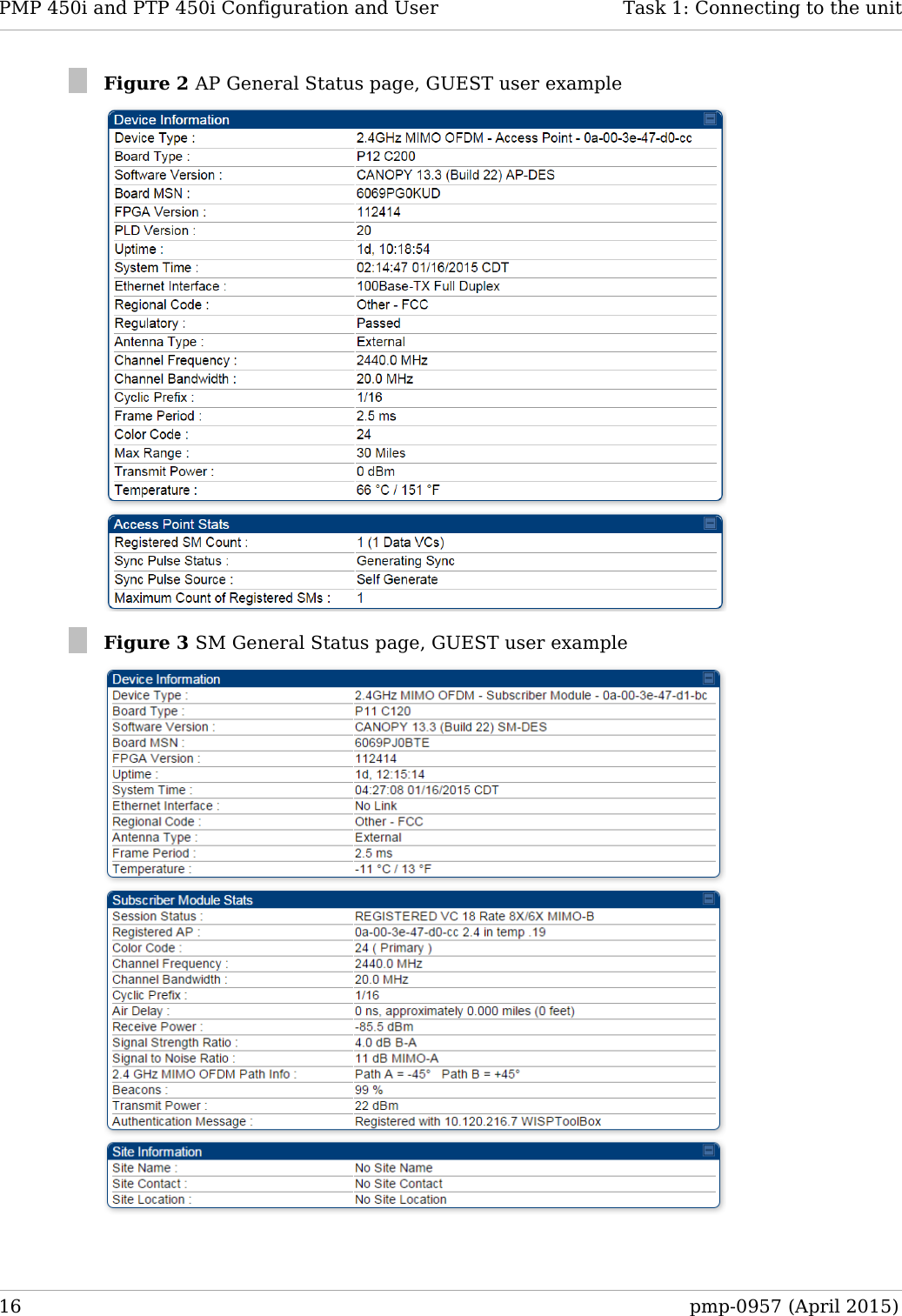
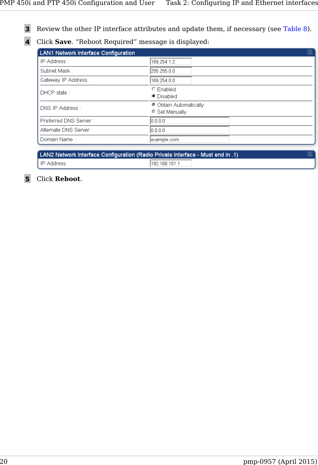
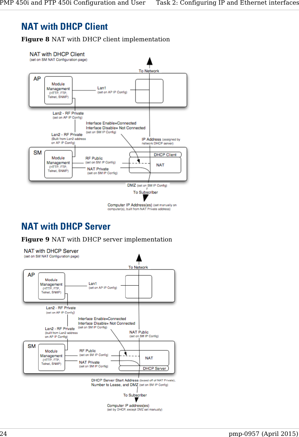
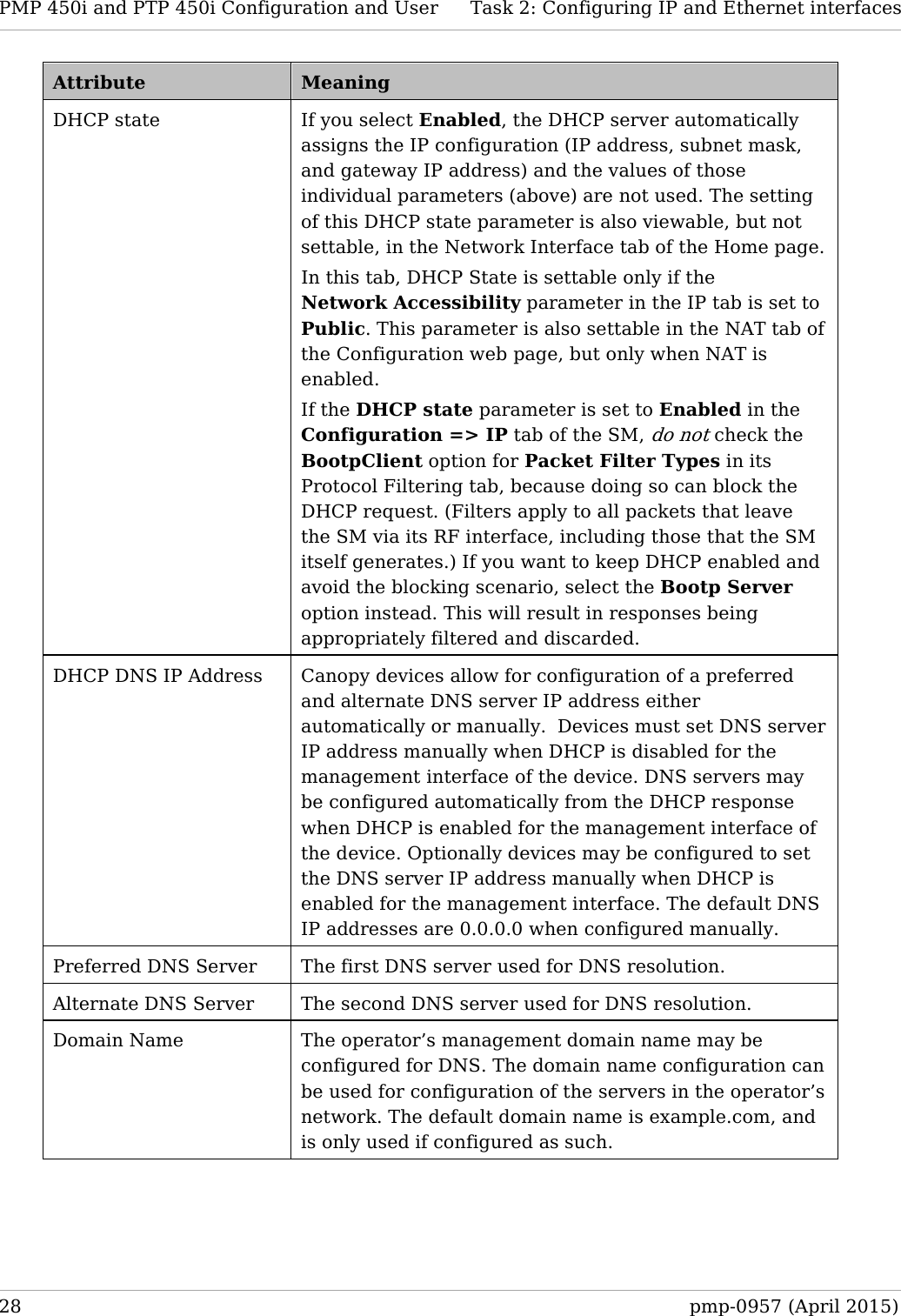
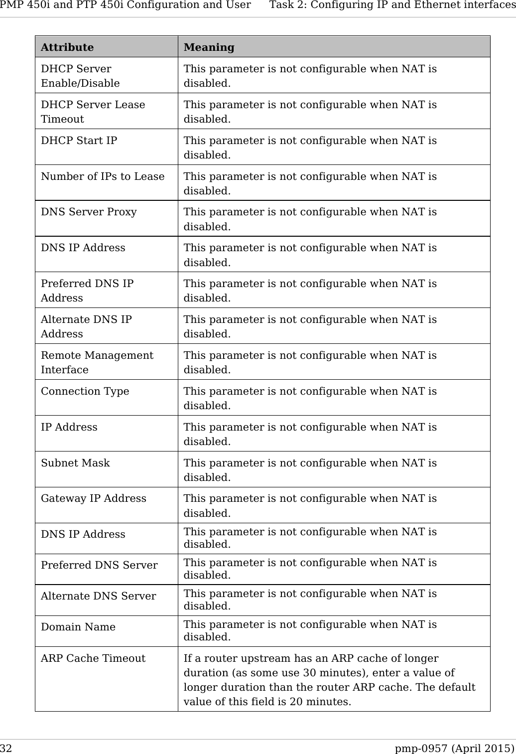
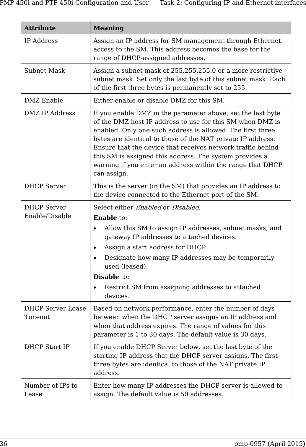
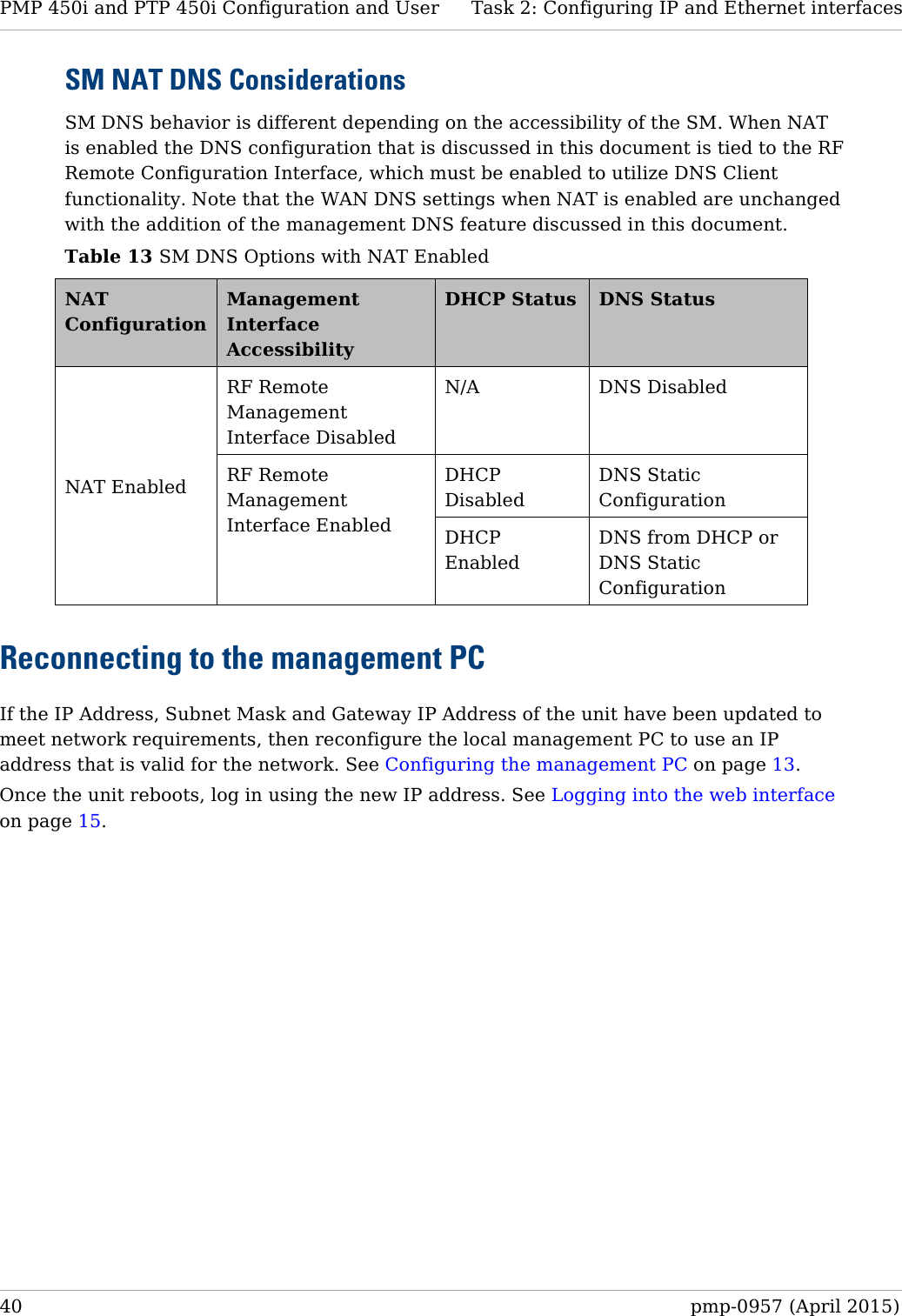
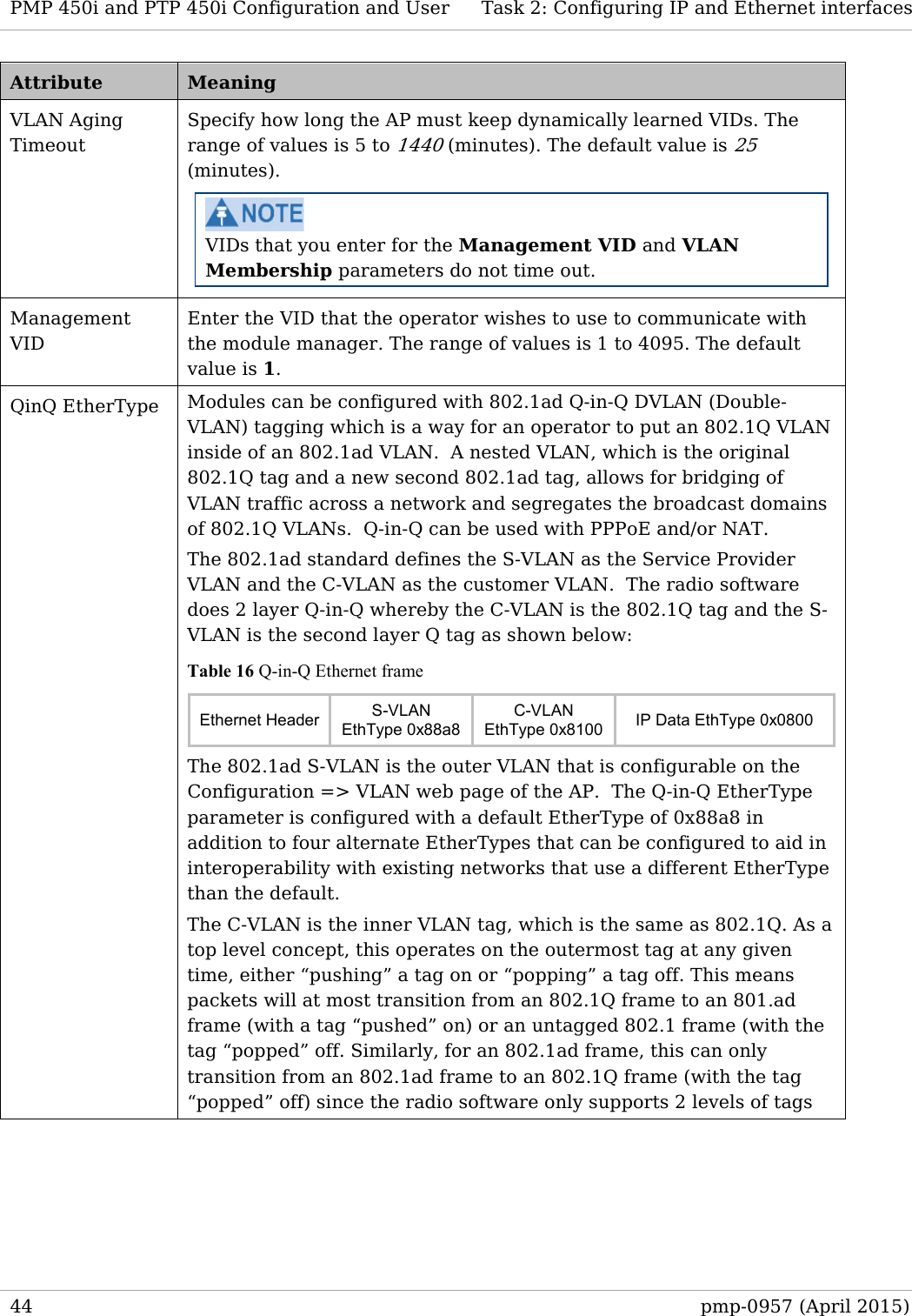
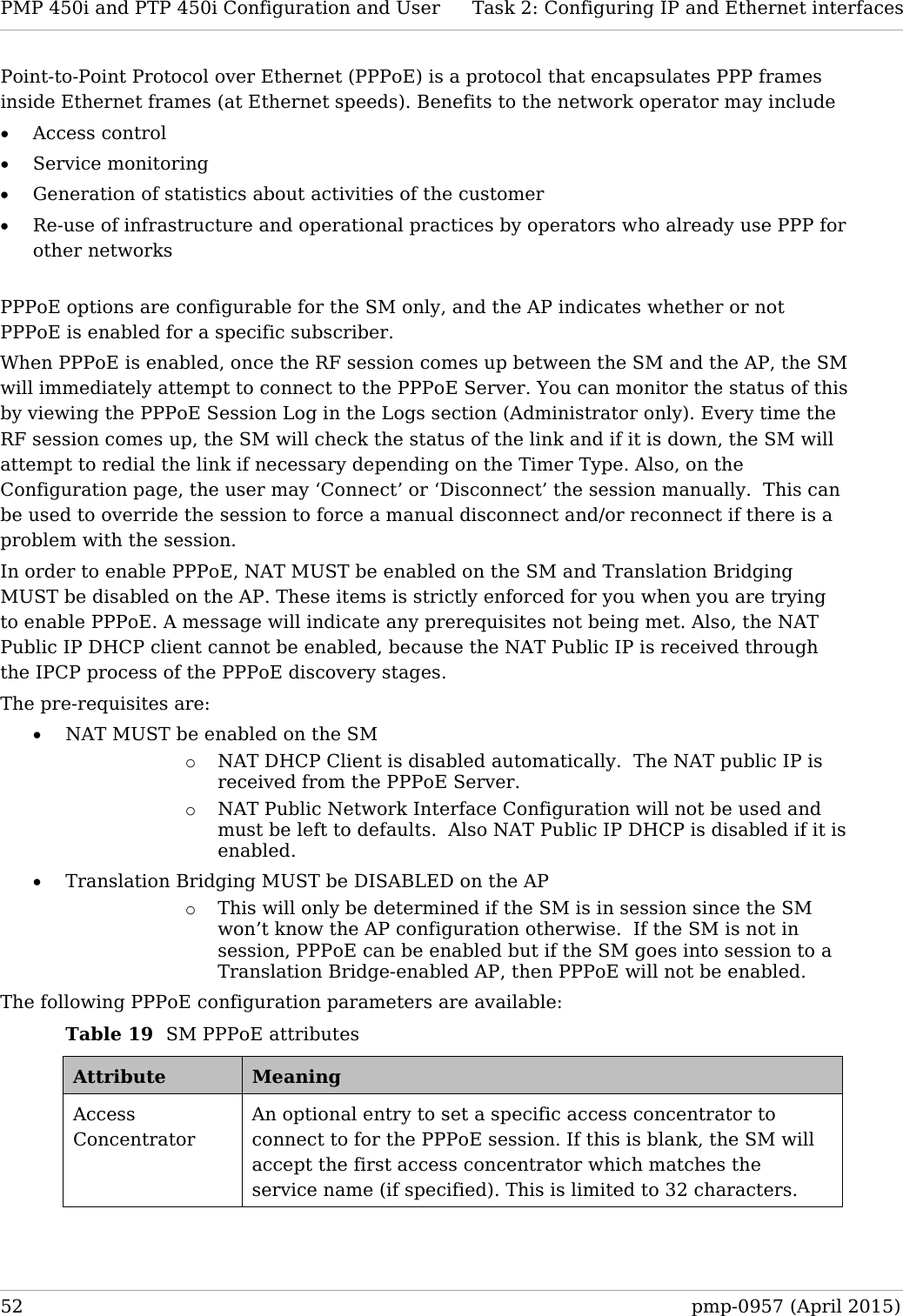
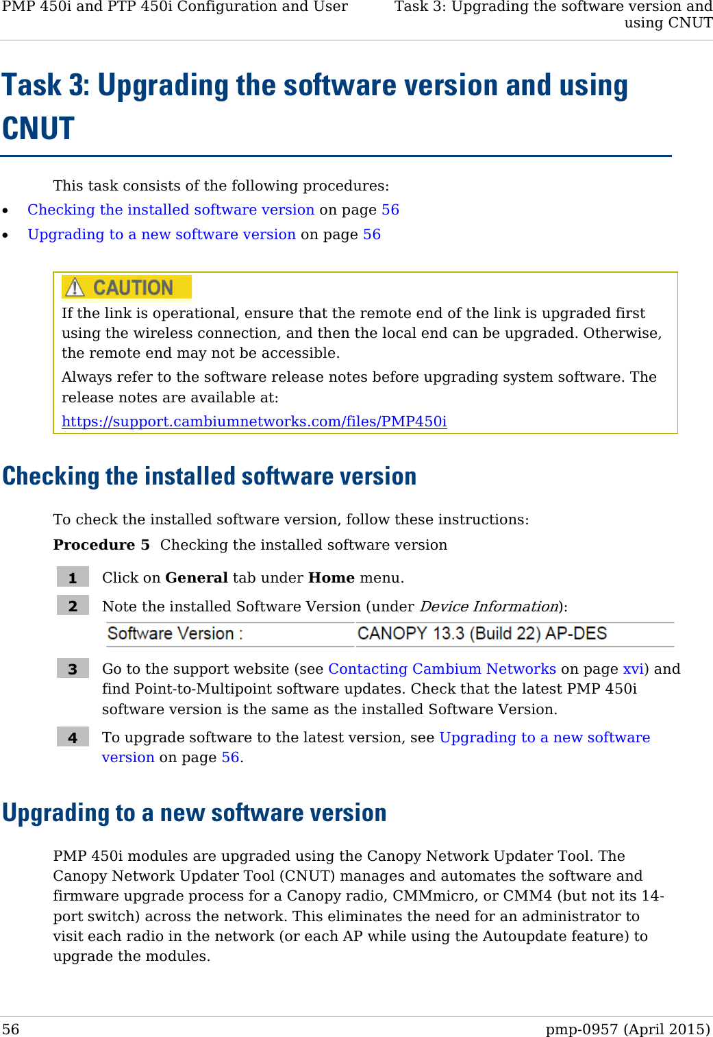

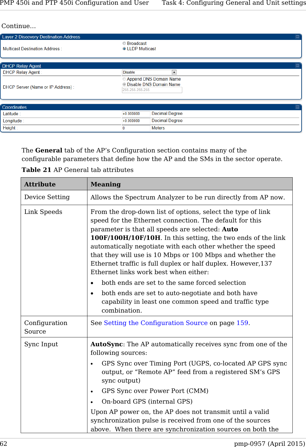
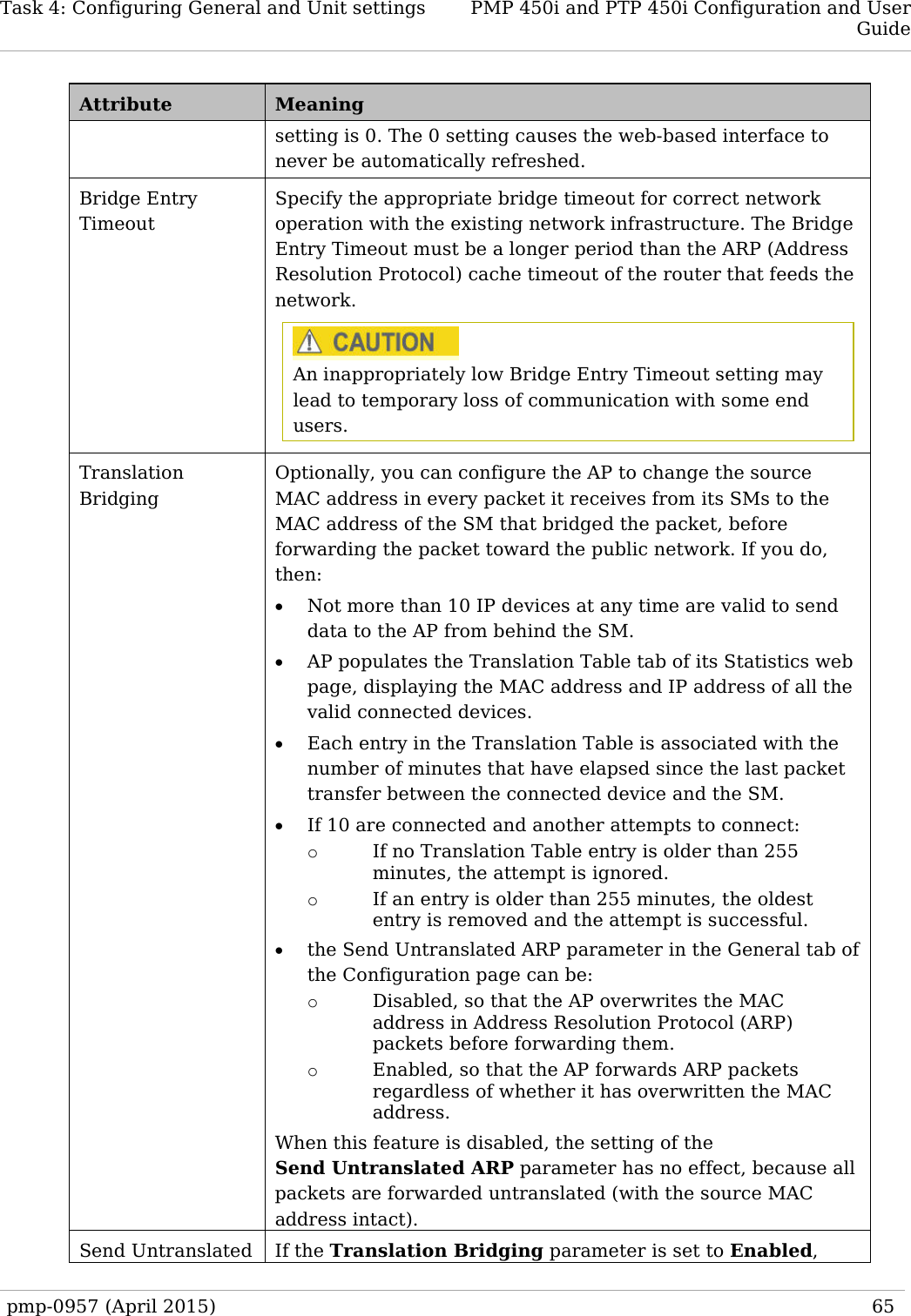
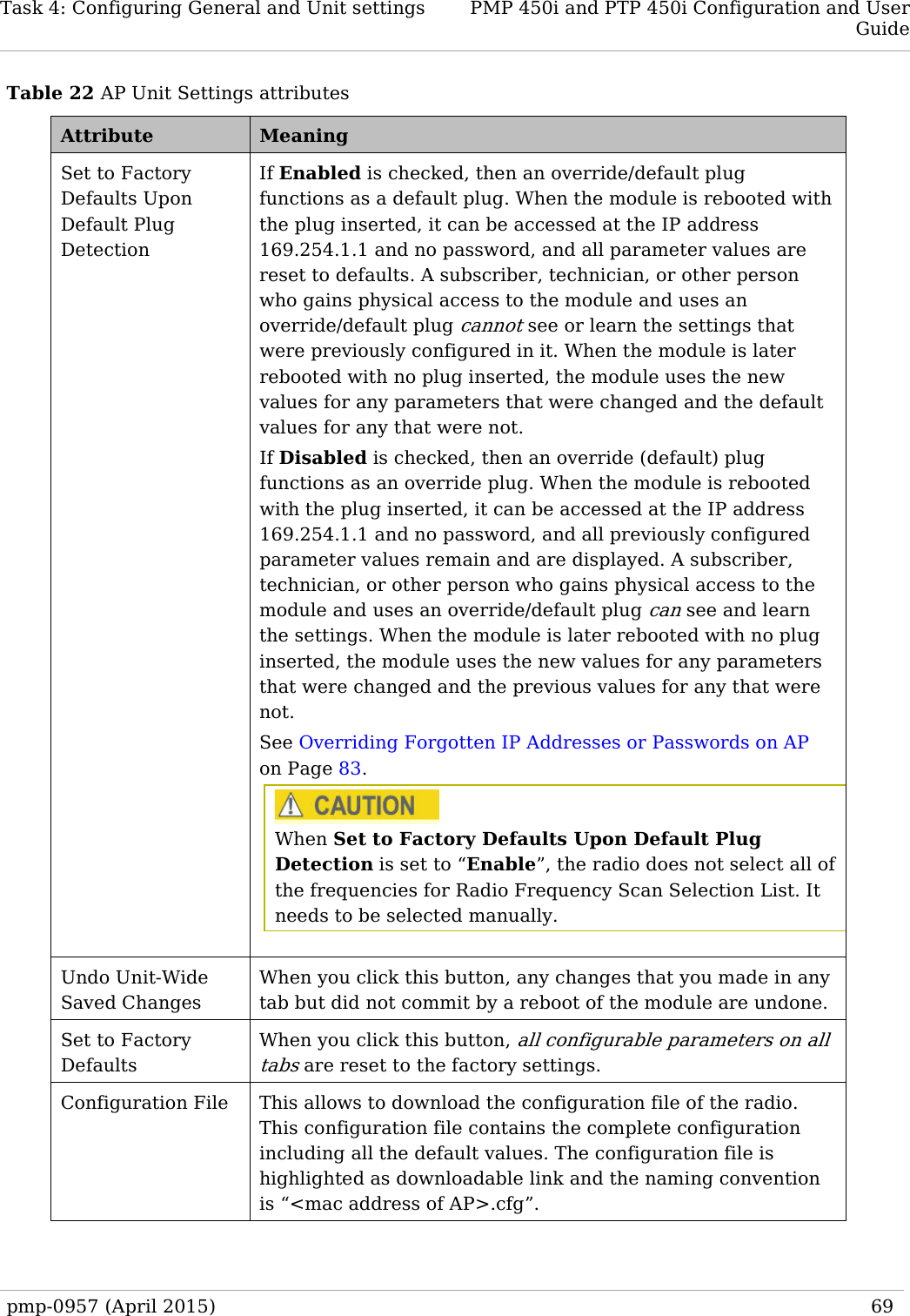
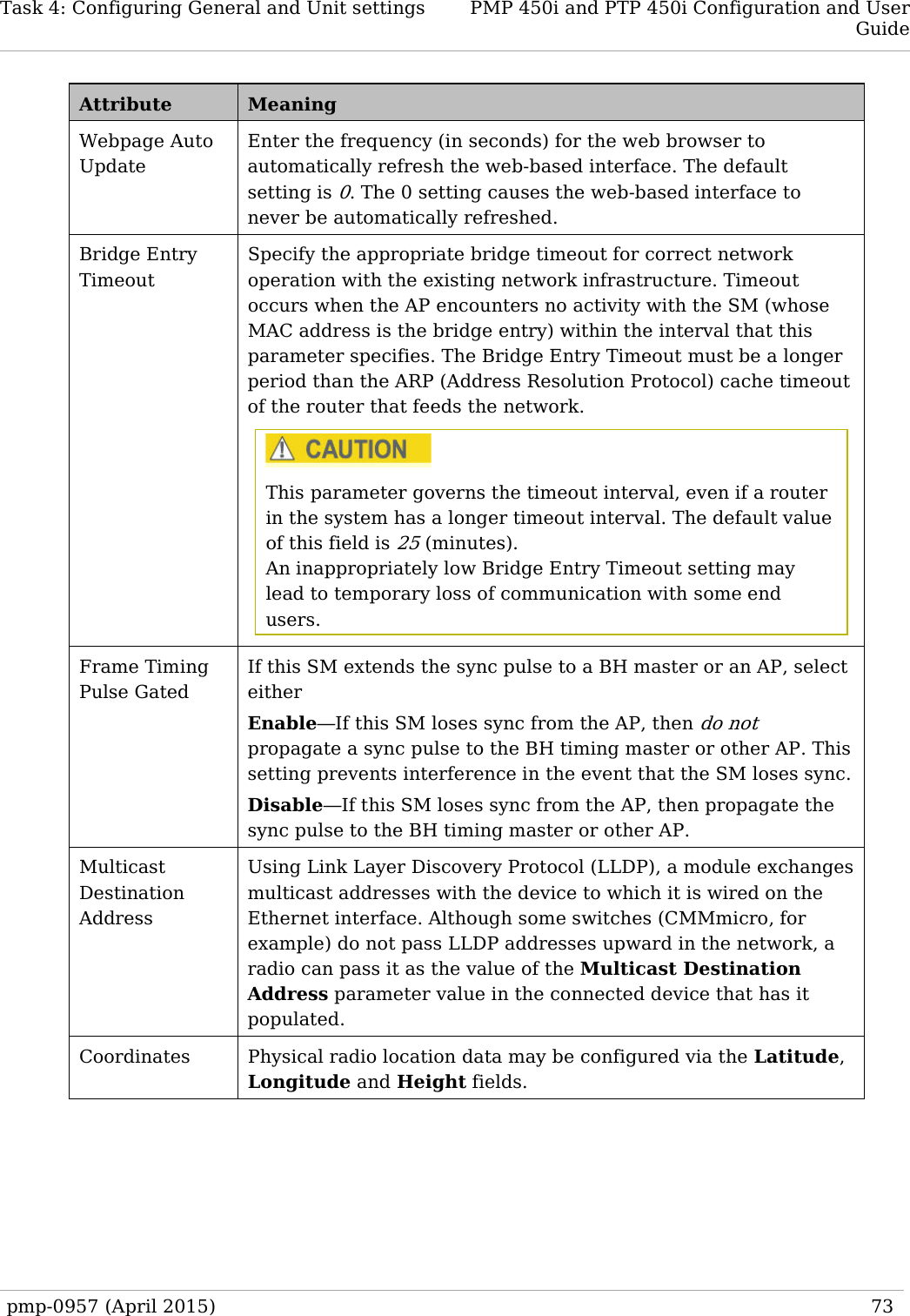
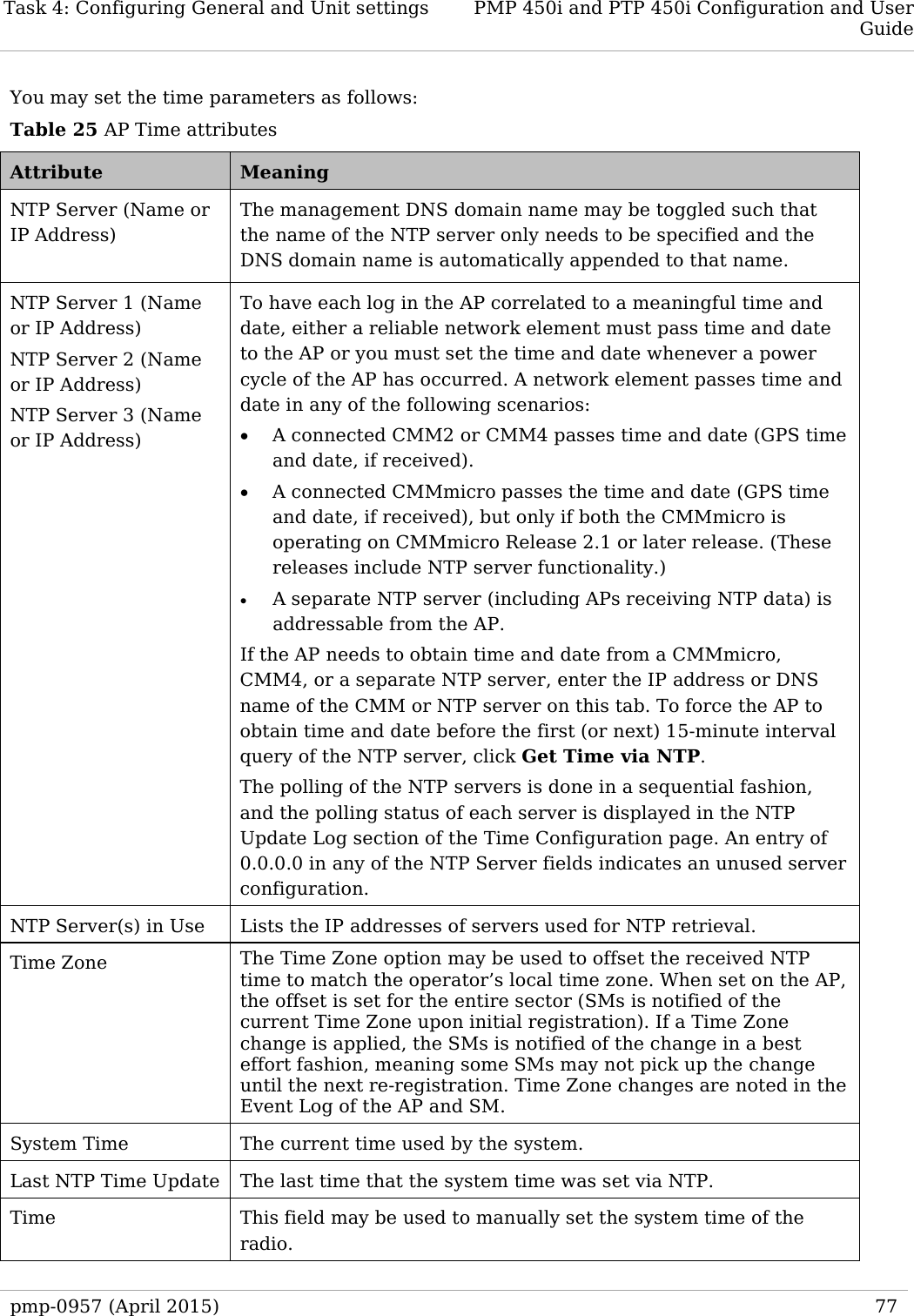
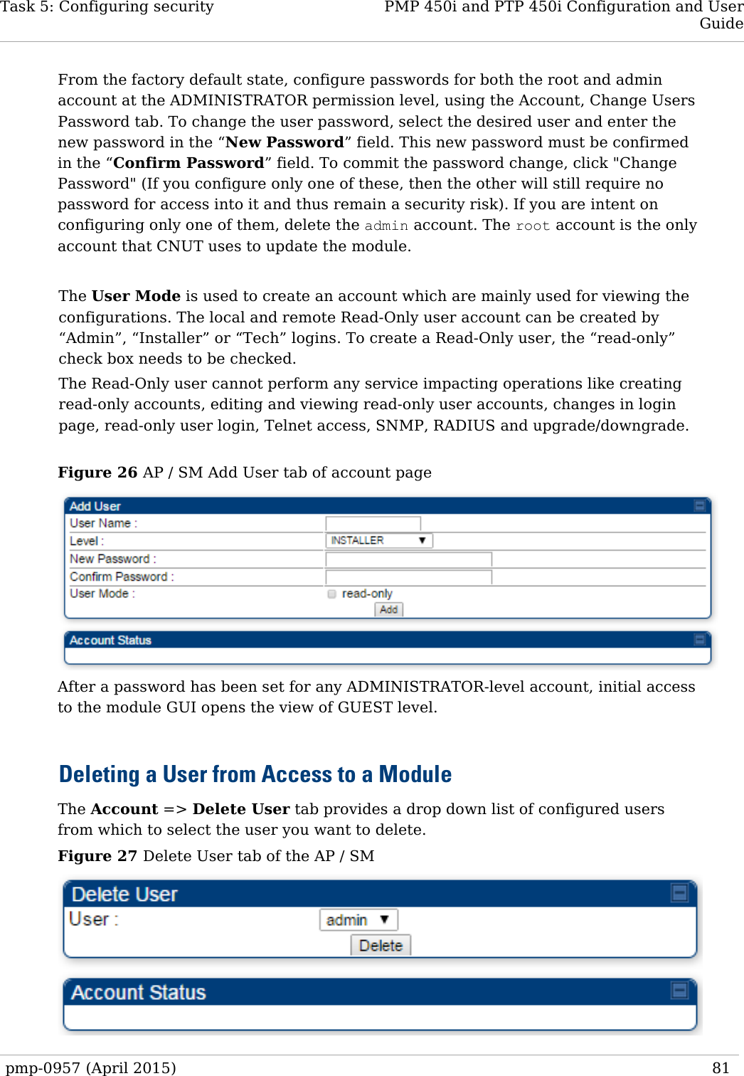
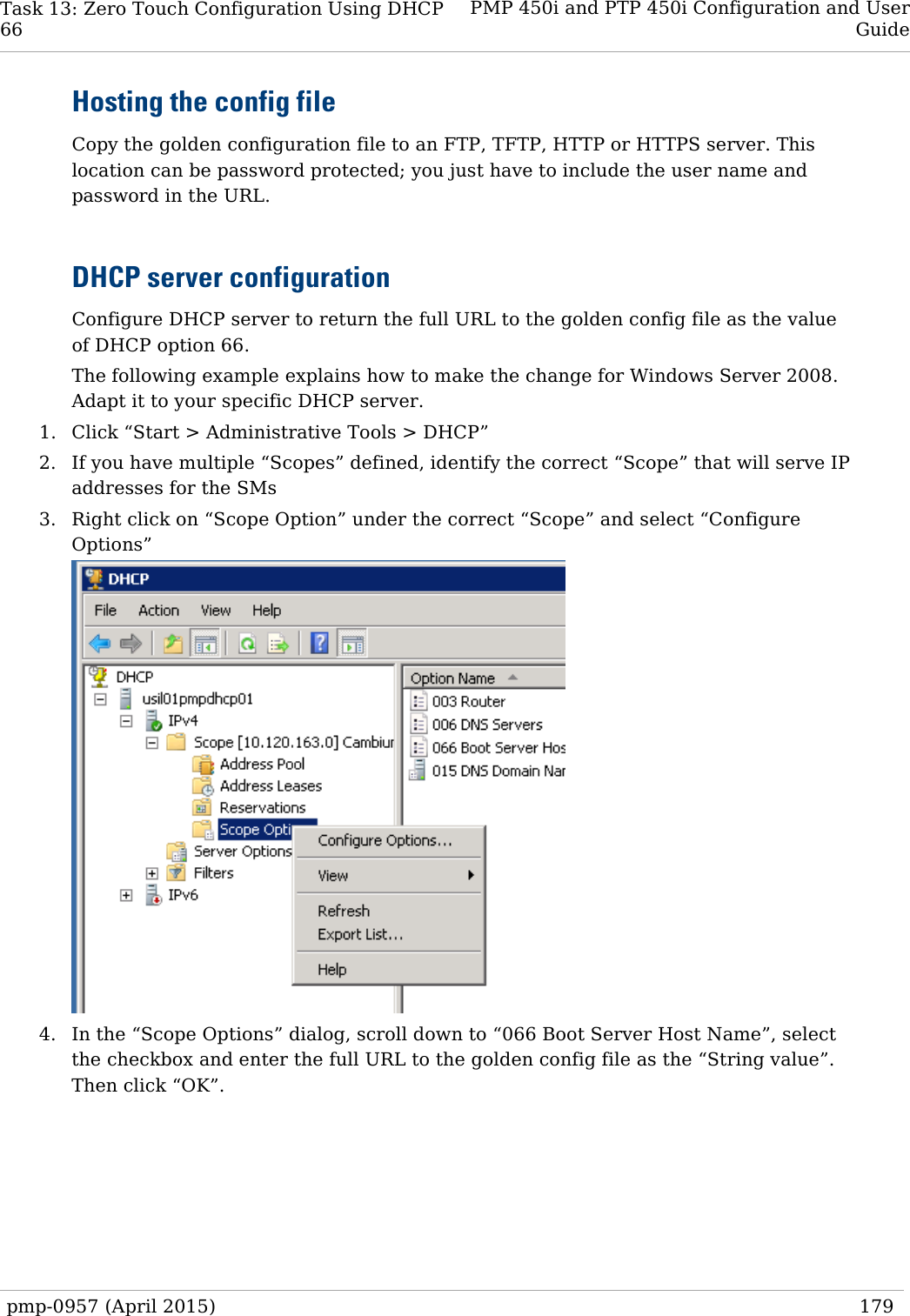
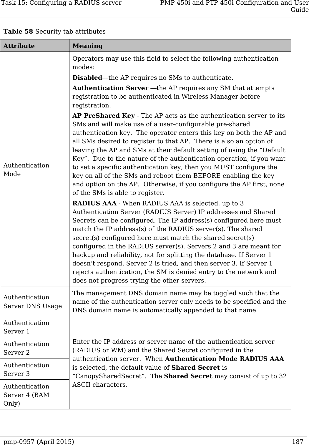
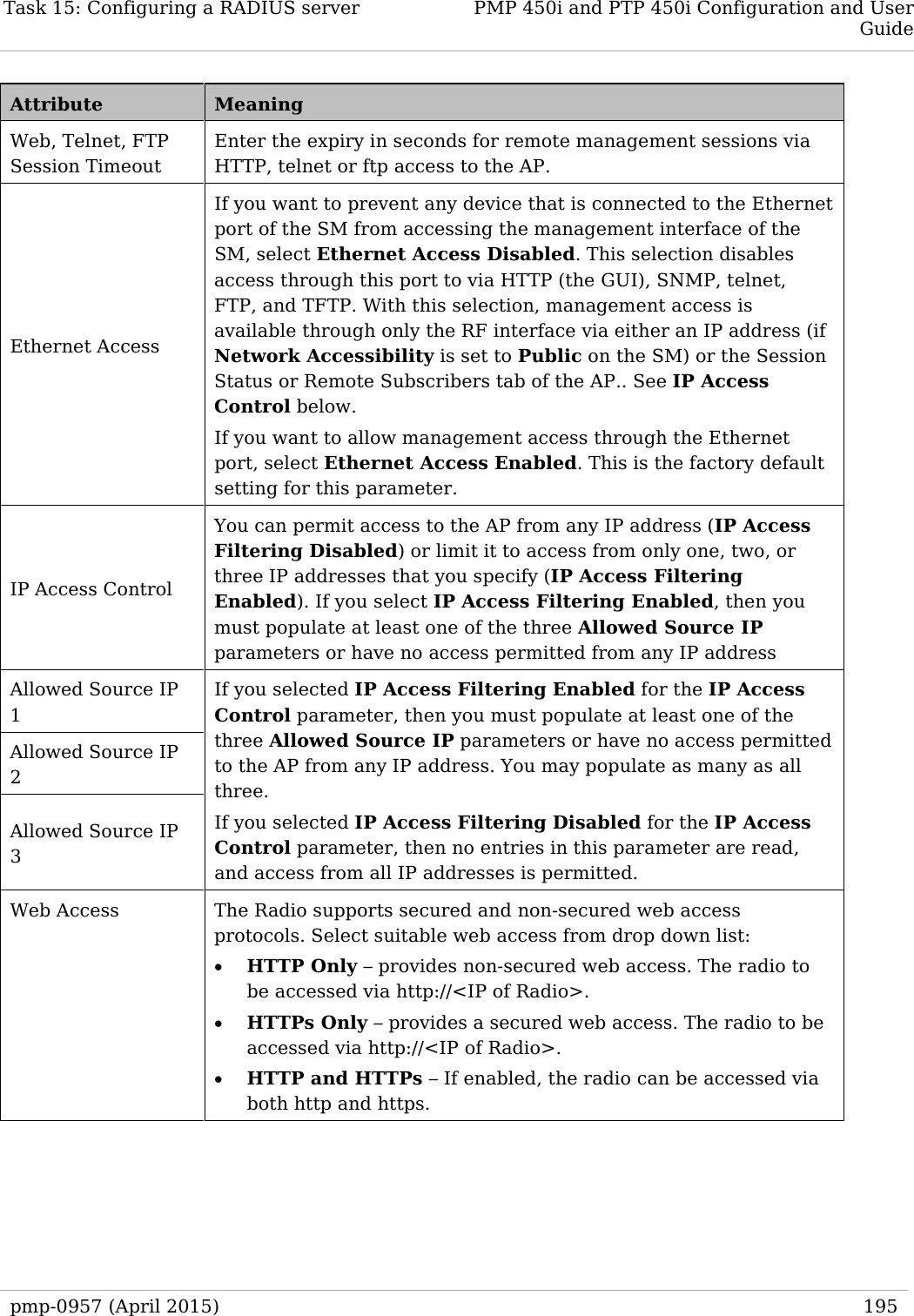
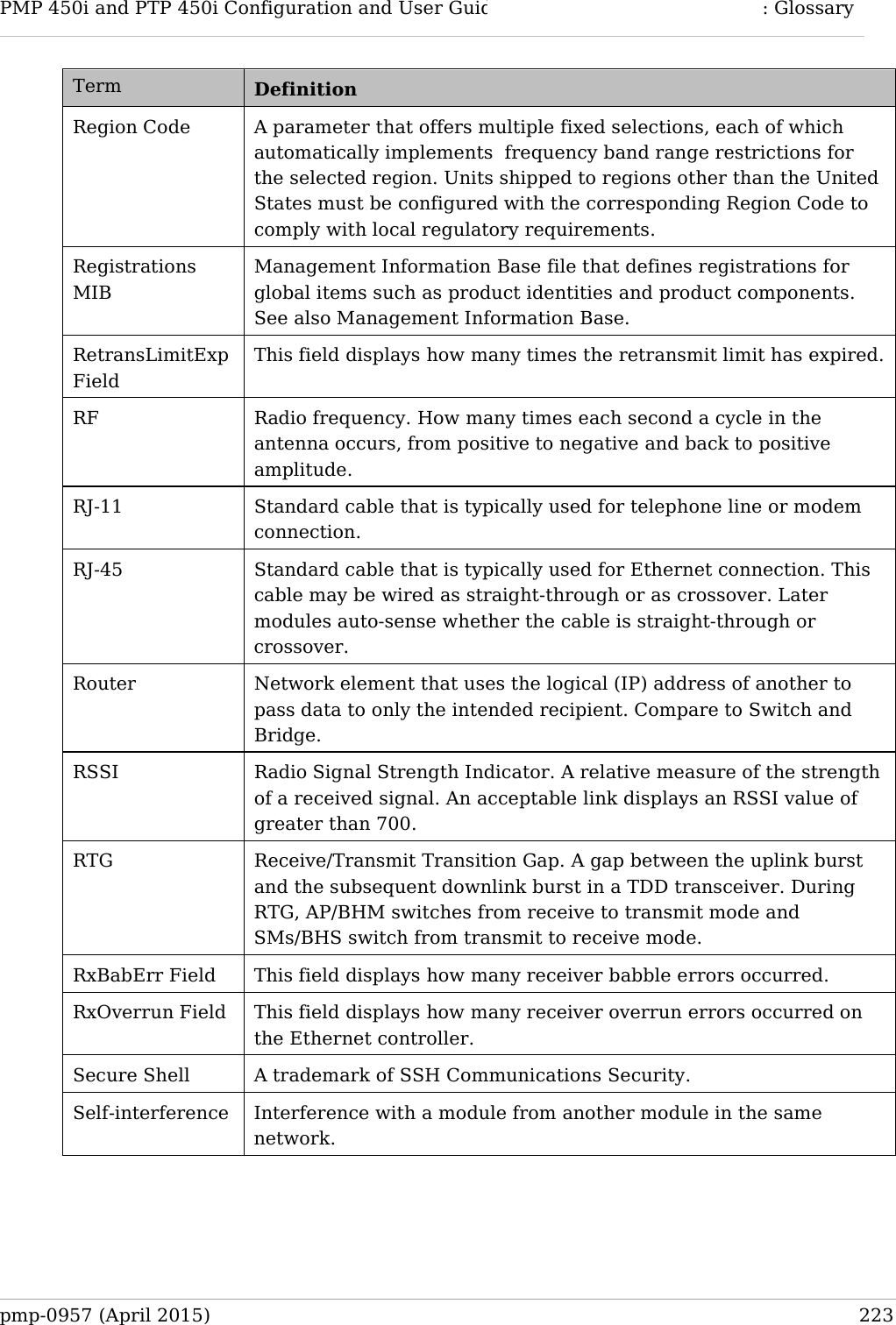
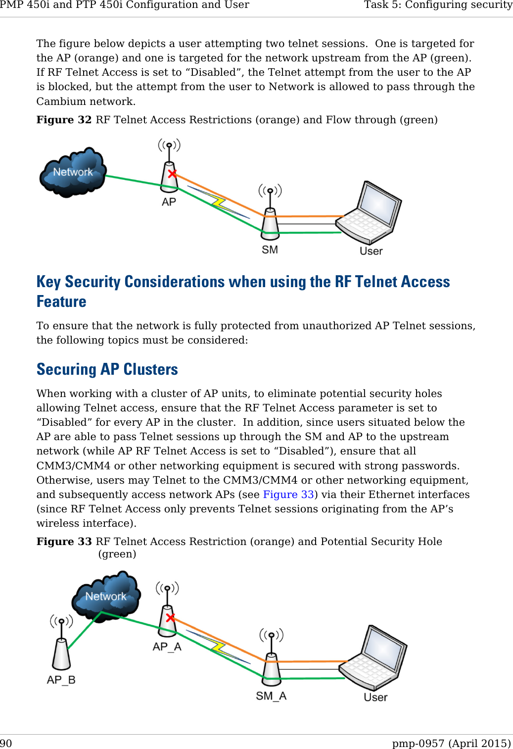
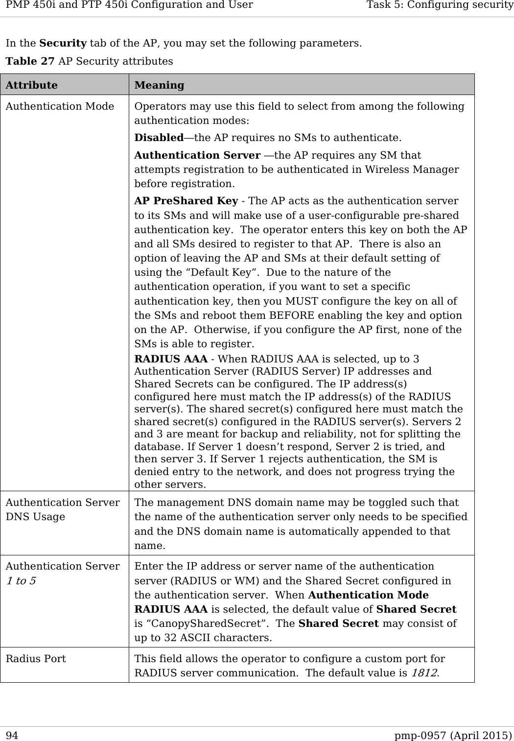
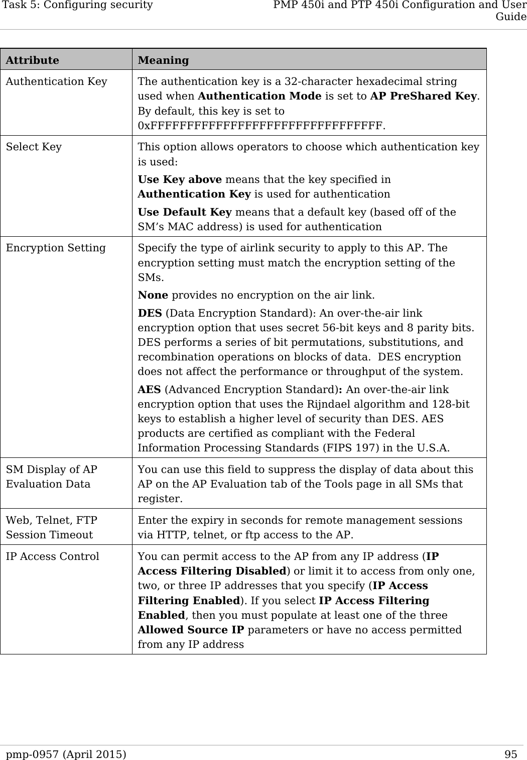
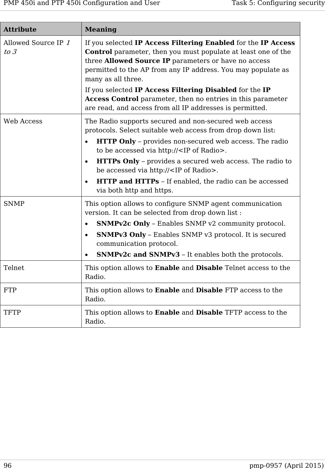
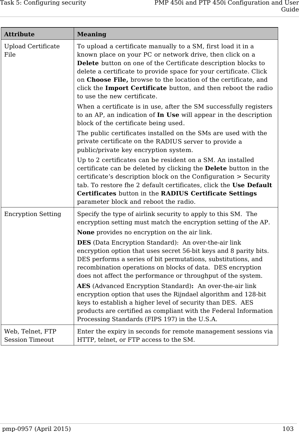
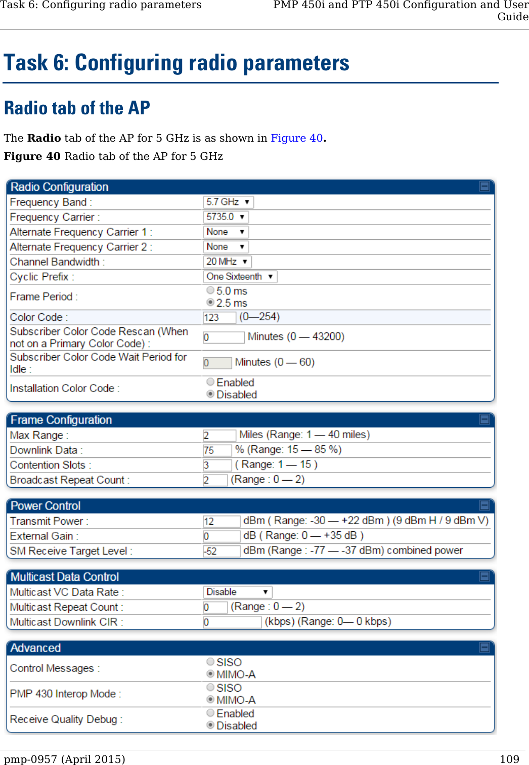
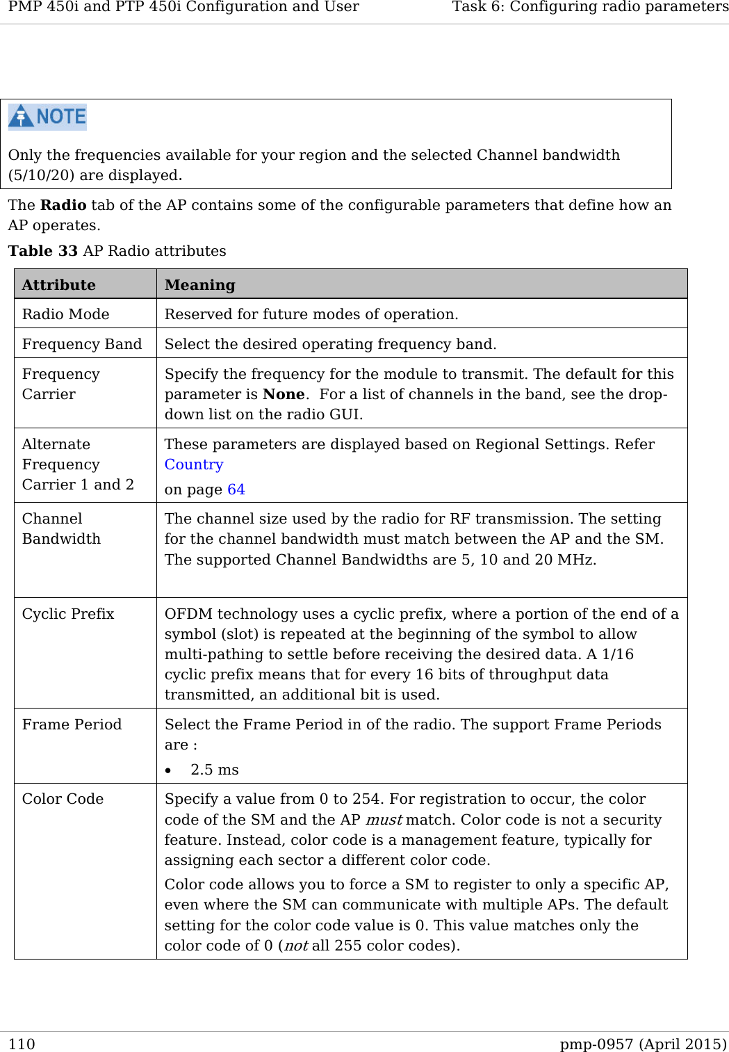
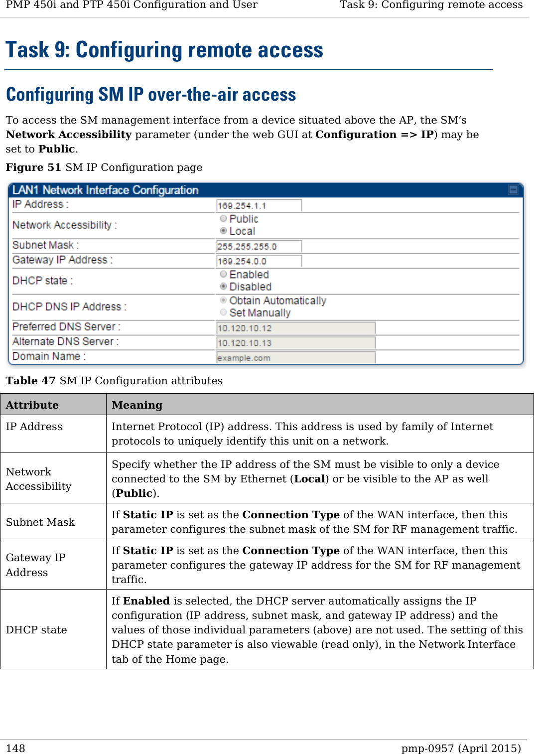
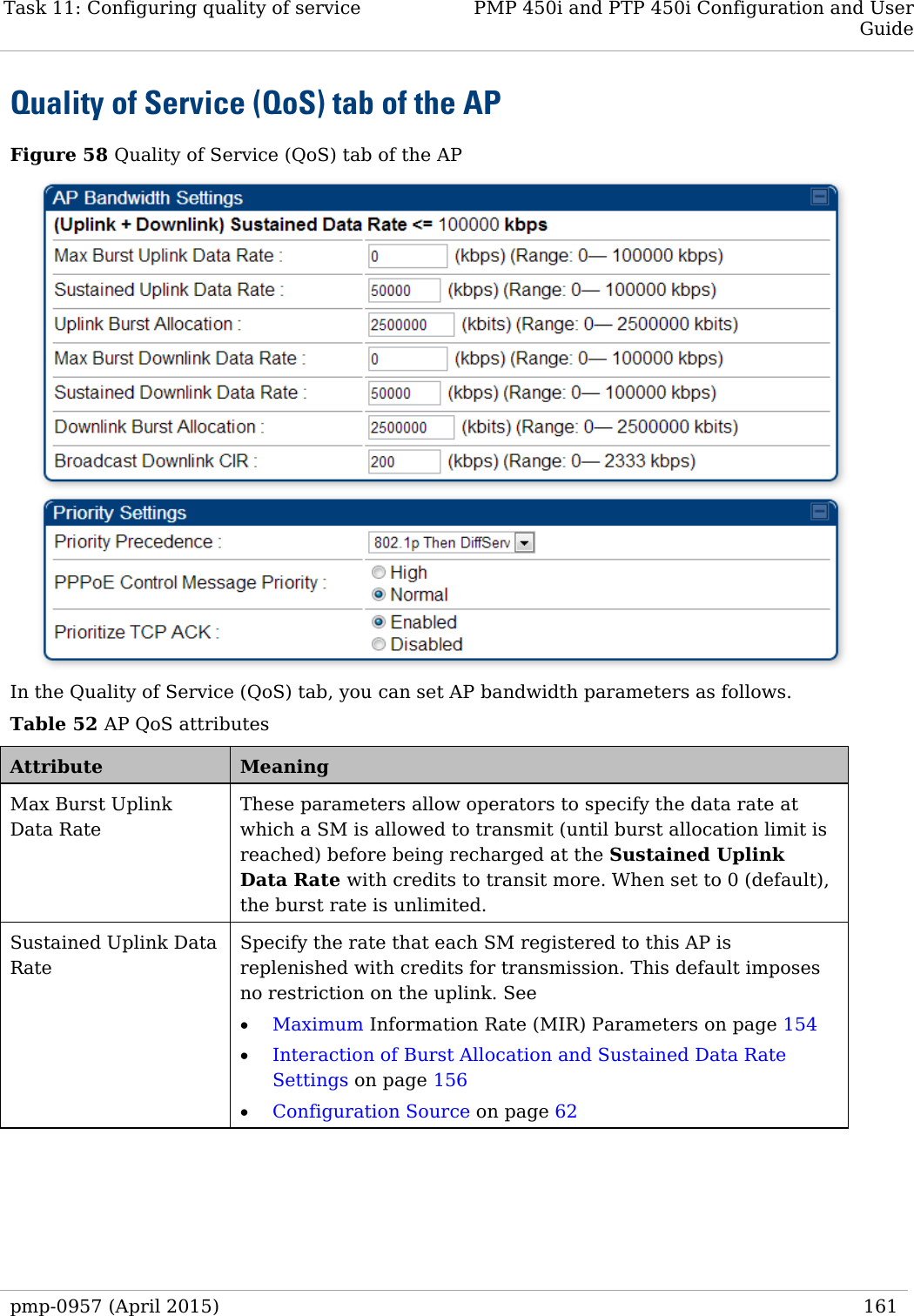
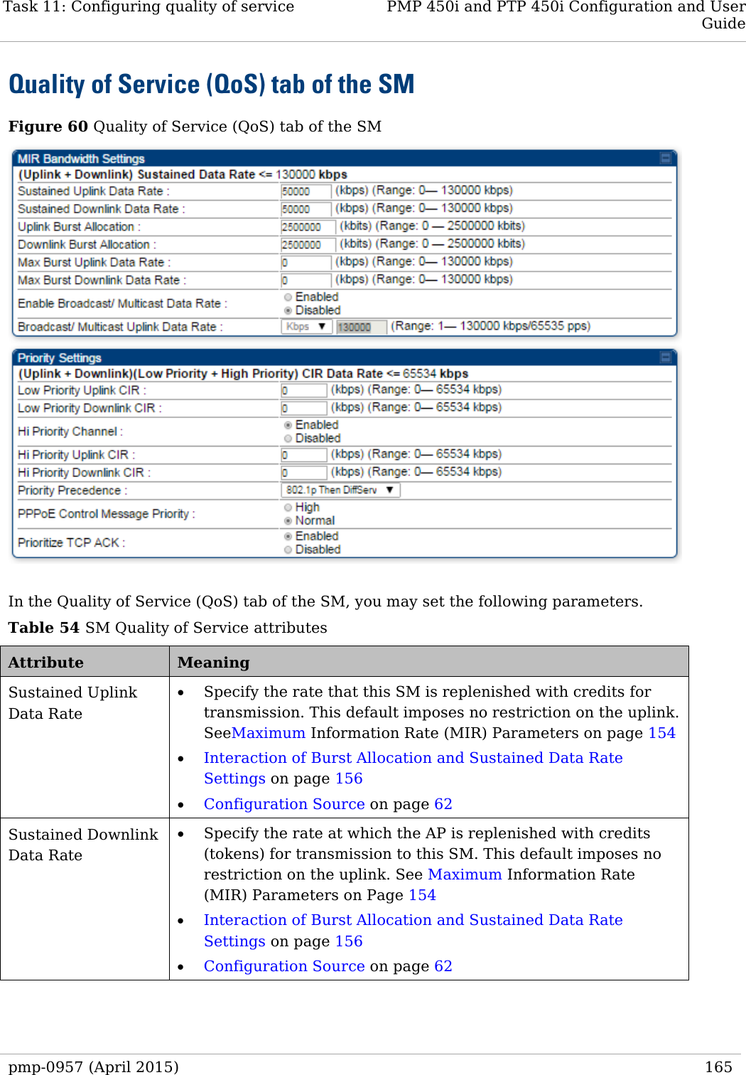
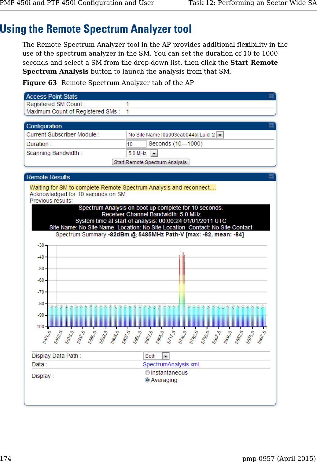
![Task 5: Configuring security PMP 450i and PTP 450i Configuration and User Guide • IP Access Filtering Disabled, then management access is allowed from any IP address, even if the Allowed Source IP 1 to 3 parameters are populated. • IP Access Filtering Enabled, and specify at least one address in the Allowed Source IP 1 to 3 parameter, then management access is limited to the specified address(s). If you intend to use Wireless Manager to manage the element, then you must ensure that the IP address of the Wireless Manager server is listed here. Configuring management IP by DHCP The IP tab in the Configuration web page of every radio contains a LAN1 Network Interface Configuration, DHCP State parameter that, if enabled, causes the IP configuration (IP address, subnet mask, and gateway IP address) to be obtained through DHCP instead of the values of those individual parameters. The setting of this DHCP state parameter is also viewable, but is not settable, in the Network Interface tab of the Home page. In the SM, this parameter is settable • in the NAT tab of the Configuration web page, but only if NAT is enabled. • in the IP tab of the Configuration web page, but only if the Network Accessibility parameter in the IP tab is set to Public. Restricting radio Telnet access over the RF interface RF Telnet Access restricts Telnet access to the AP from a device situated below a network SM (downstream from the AP). This is a security enhancement to restrict RF-interface sourced AP access specifically to the LAN1 IP address and LAN2 IP address (Radio Private Address, typically 192.168.101.[LUID]). This restriction disallows unauthorized users from running Telnet commands on the AP that can change AP configuration or modifying network-critical components such as routing and ARP tables. The RF Telnet Access may be configured via the AP GUI or via SNMP commands, and RF Telnet Access is set to “Enabled” by default. Once RF Telnet Access is set to “Disabled”, if there is a Telnet session attempt to the AP originating from a device situated below the SM (or any downstream device), the attempt is dropped. This also includes Telnet session attempts originated from the SM’s management interface (if a user has initiated a Telnet session to a SM and attempts to Telnet from the SM to the AP). In addition, if there are any active Telnet connections to the AP originating from a device situated below the SM (or any downstream device), the connection is dropped. This behavior must be considered if system administrators use Telnet downstream from an AP (from a registered SM) to modify system parameters. Setting RF Telnet Access to “Disabled” does not affect devices situated above the AP from accessing the AP via Telnet, including servers running the CNUT (Canopy Network Updater tool) application. Also, setting RF Telnet Access to “Disabled” does not affect any Telnet access into upstream devices (situated above or adjacent to the AP) through the AP (see Figure 32). pmp-0957 (April 2015) 89](https://usermanual.wiki/Cambium-Networks/50450I.Installation-Guide/User-Guide-2619716-Page-111.png)
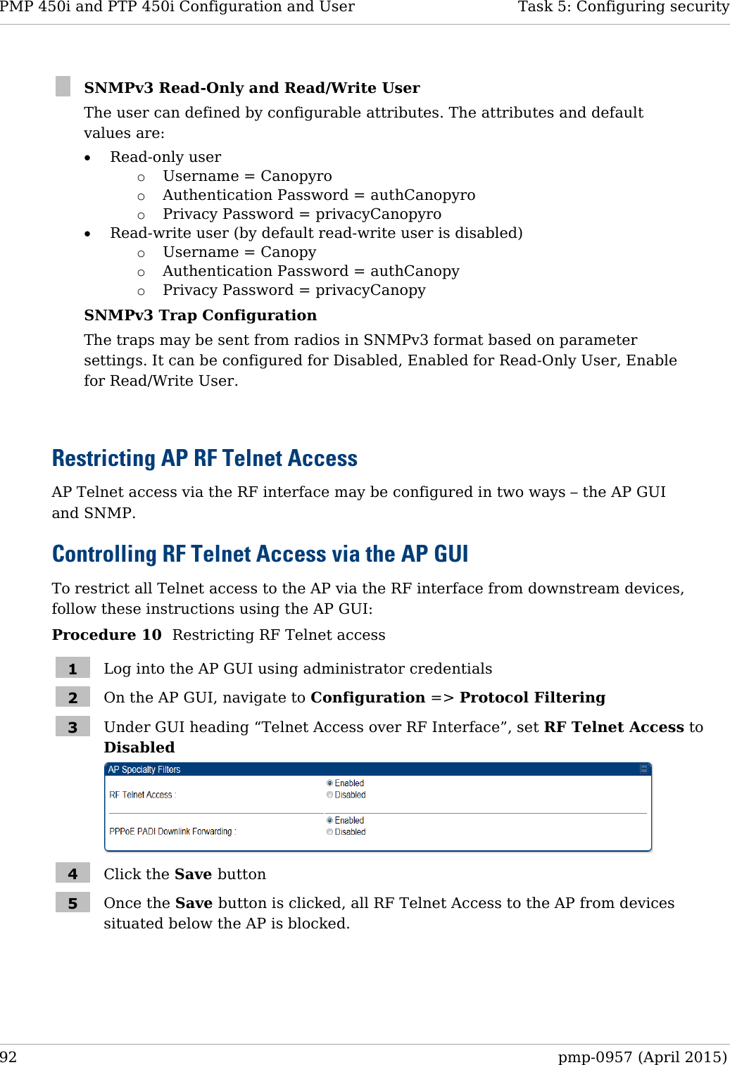
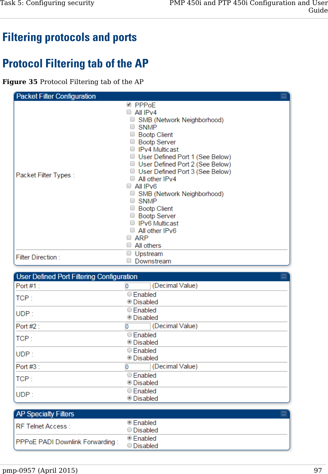
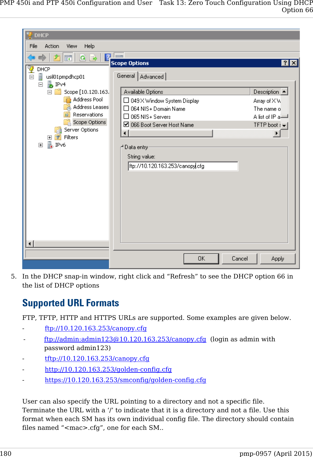
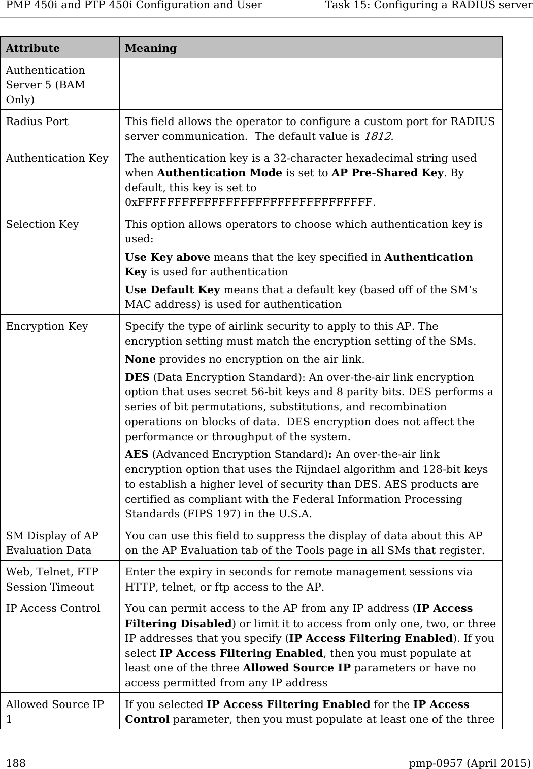
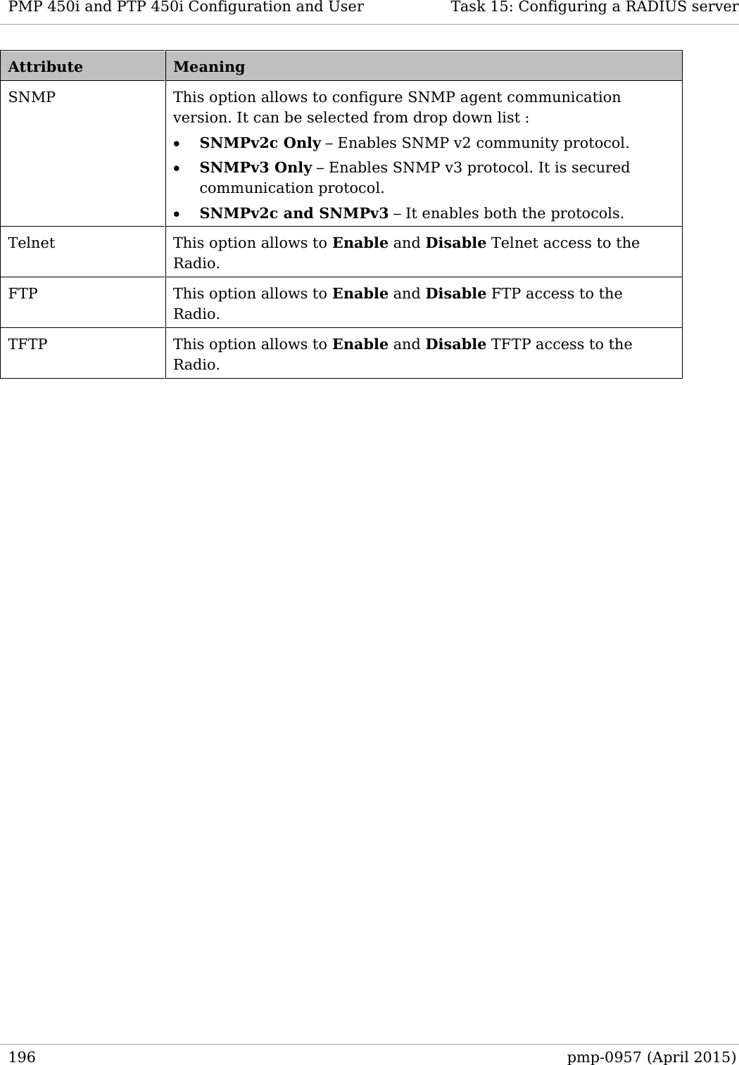
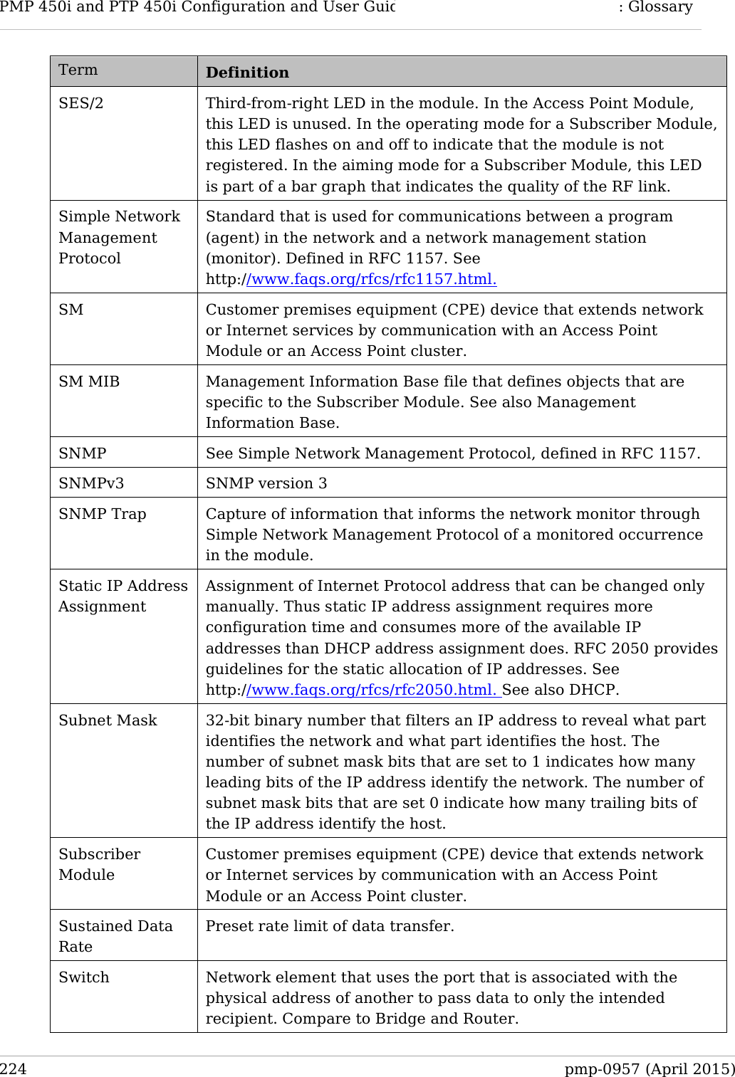
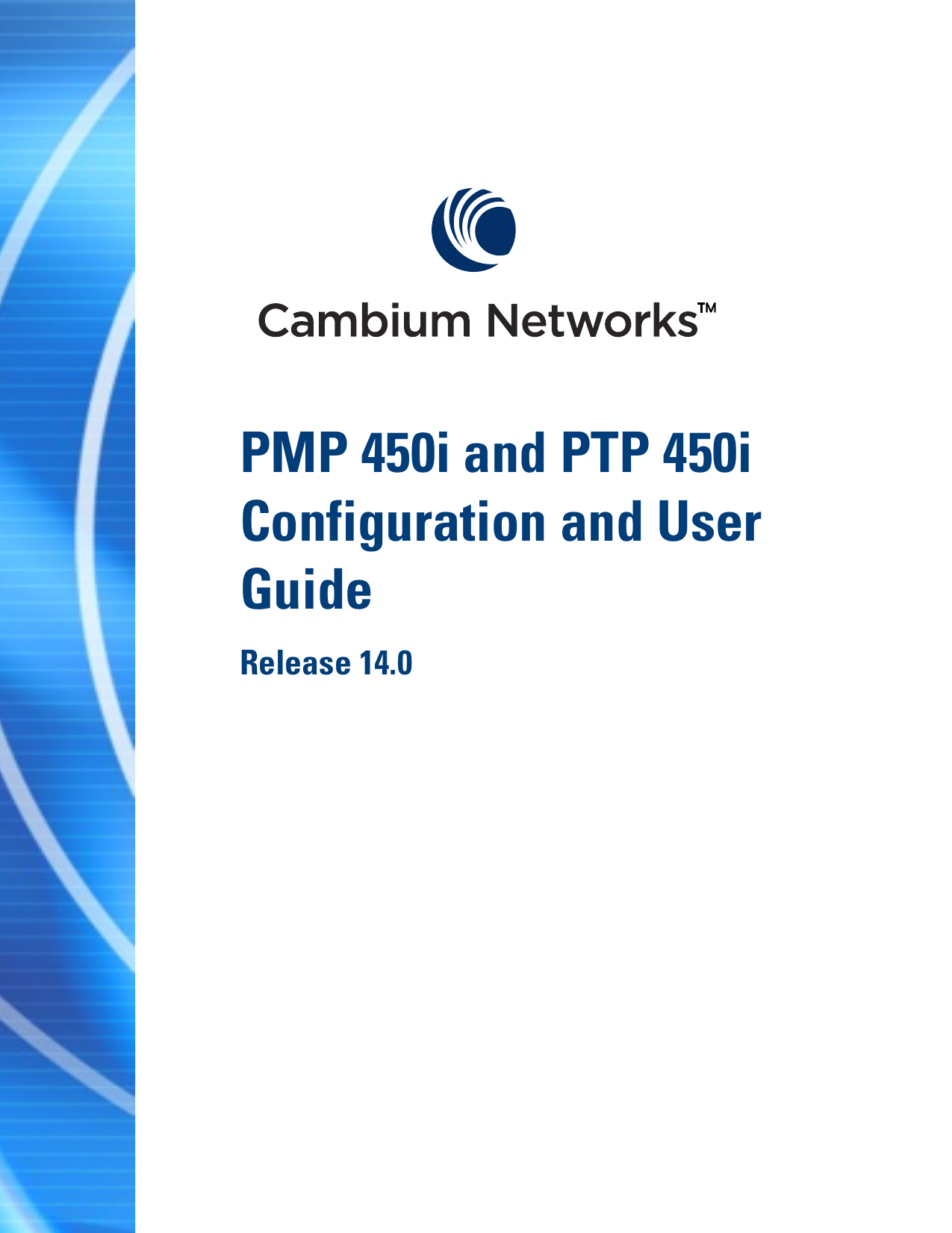
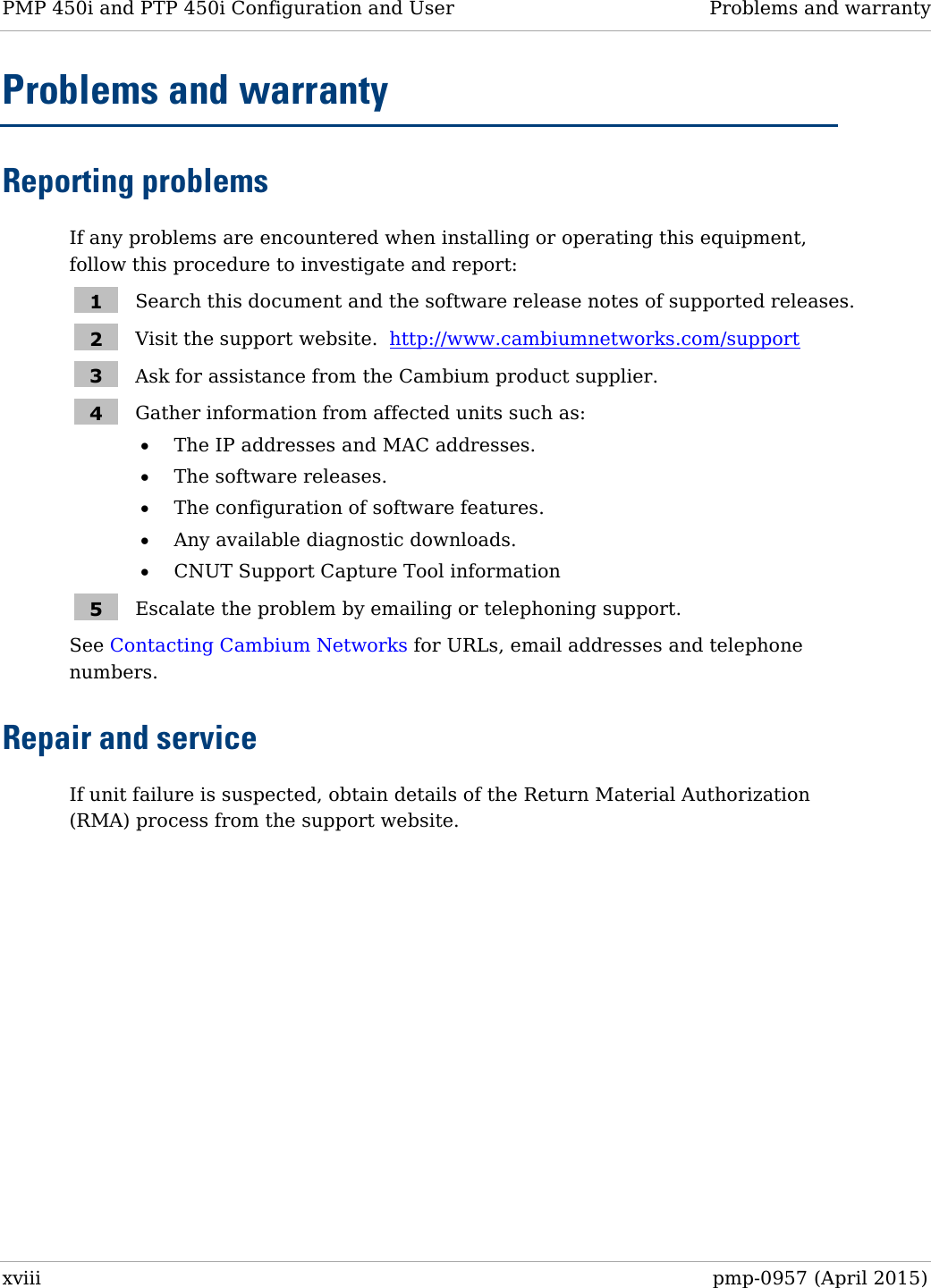
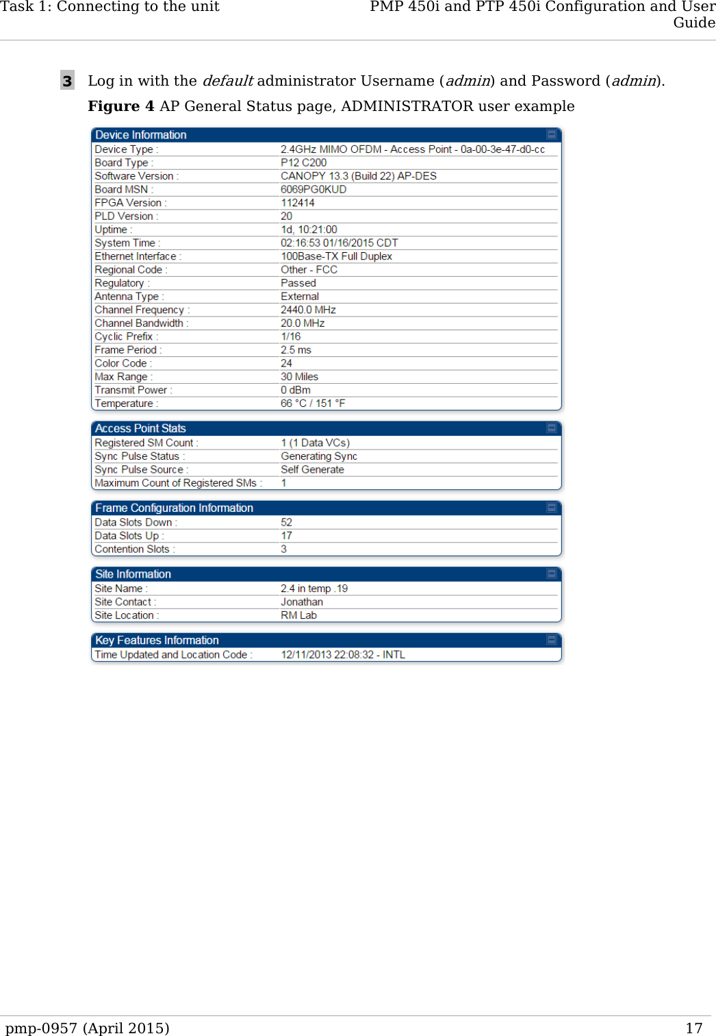
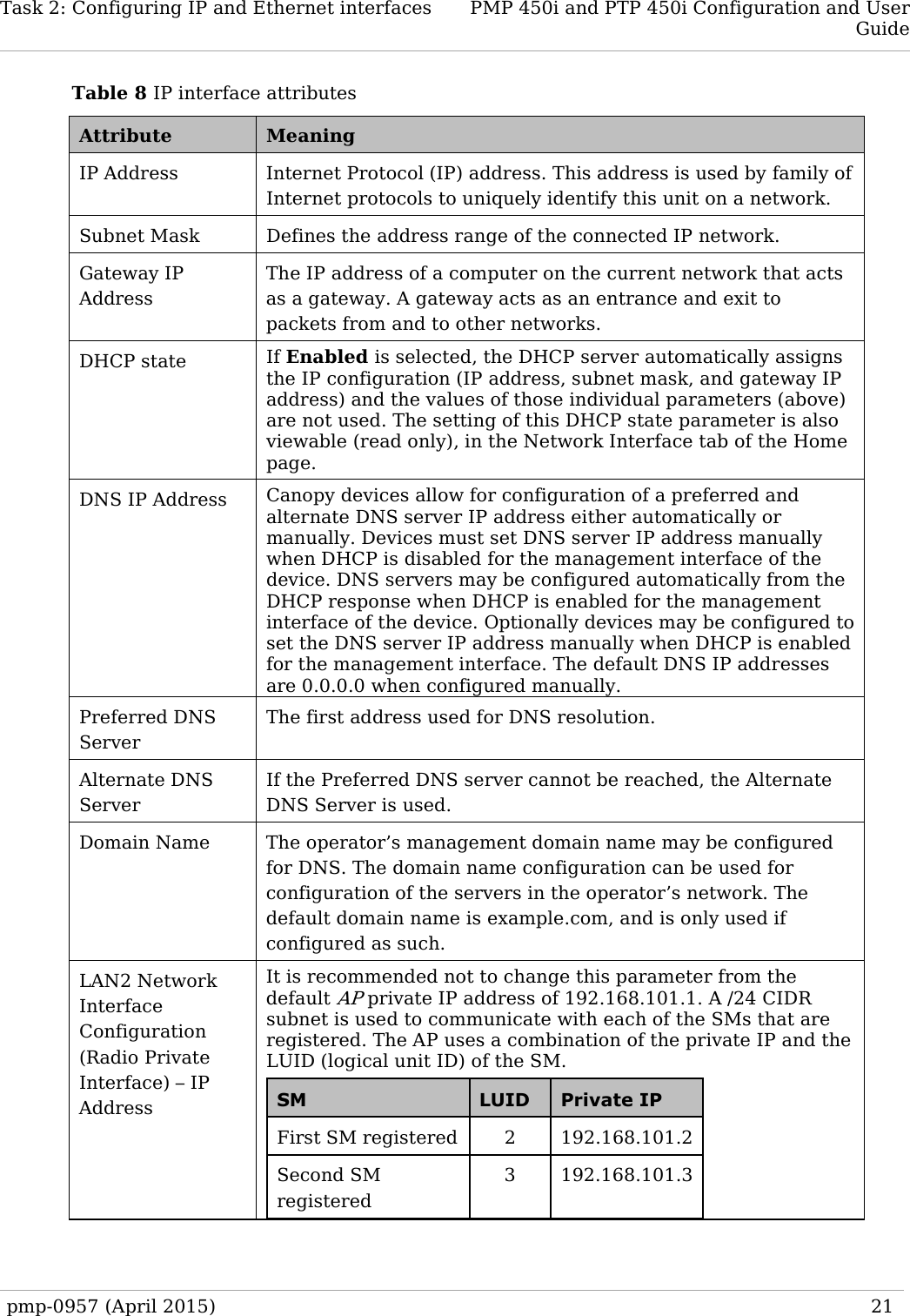
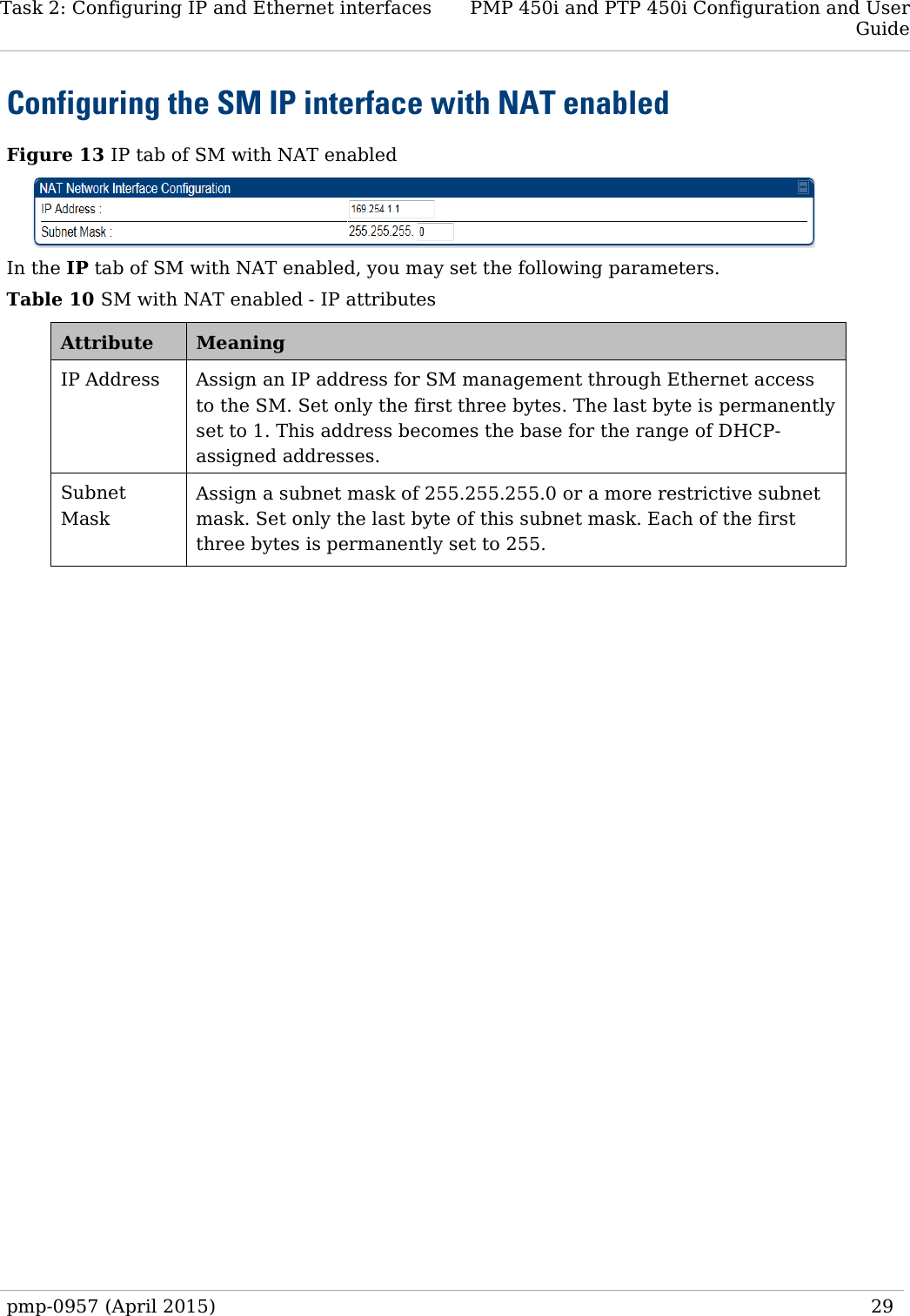
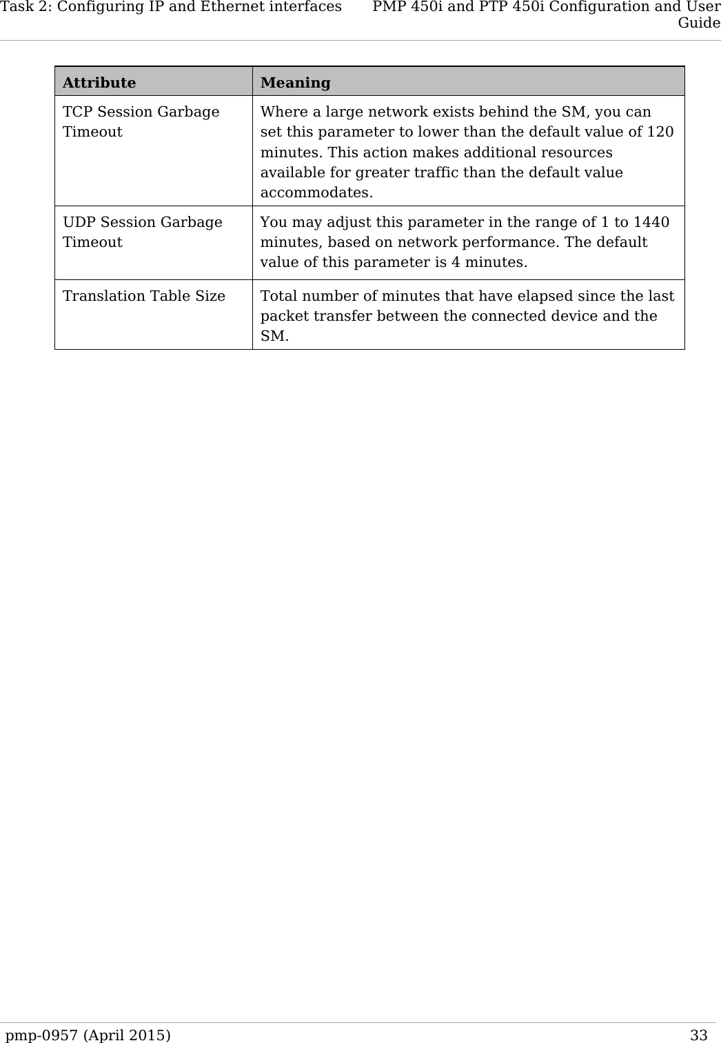
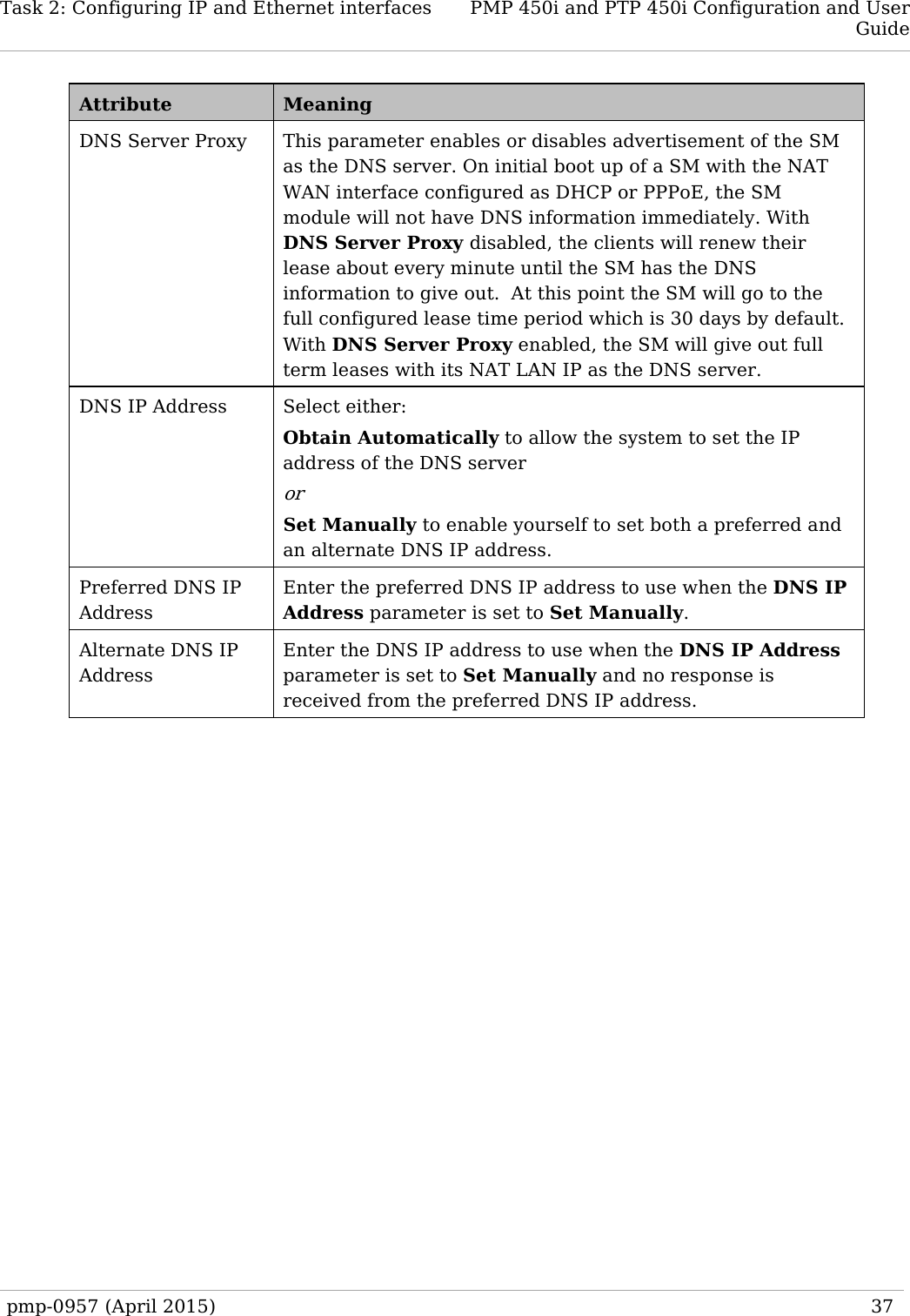
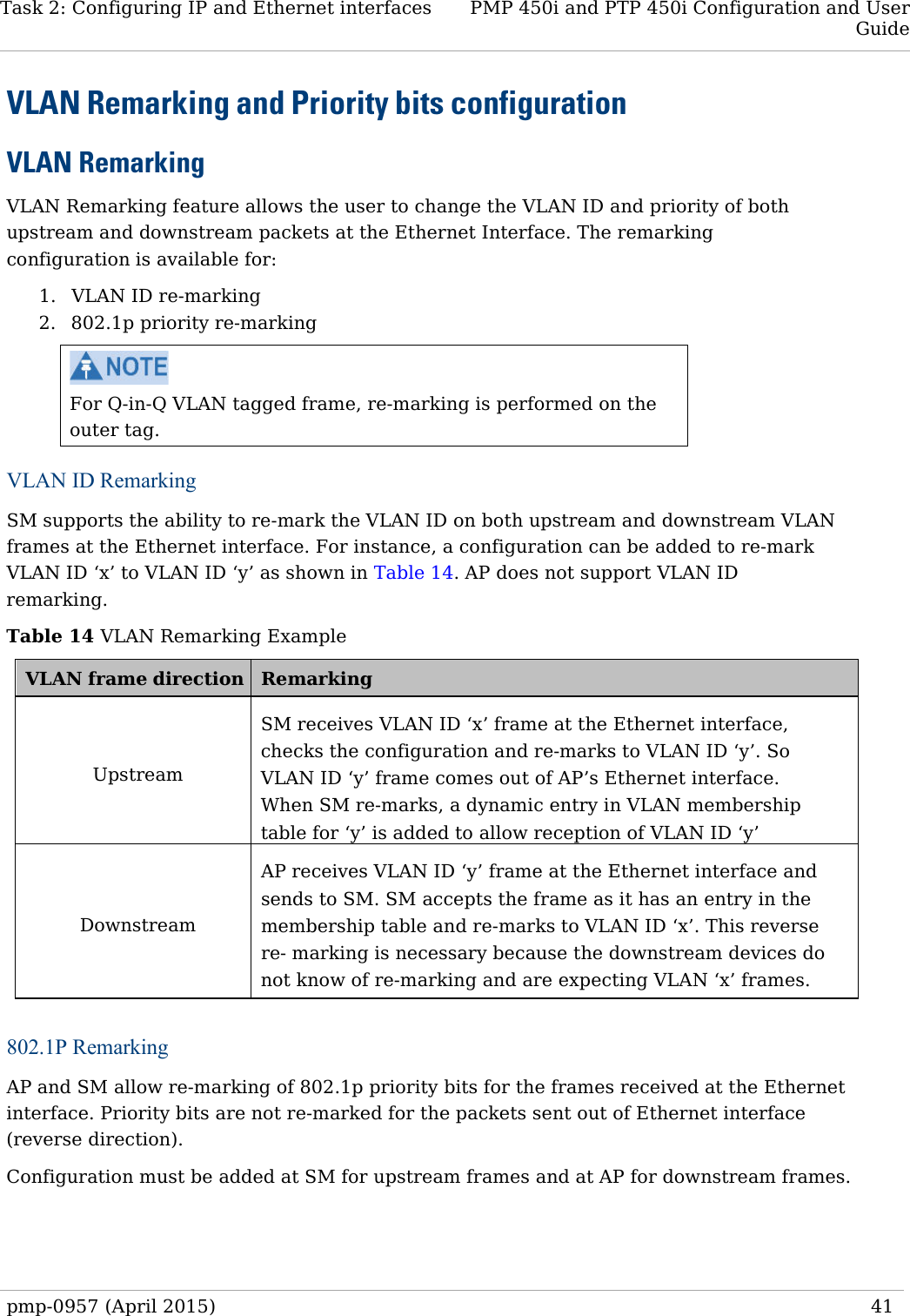
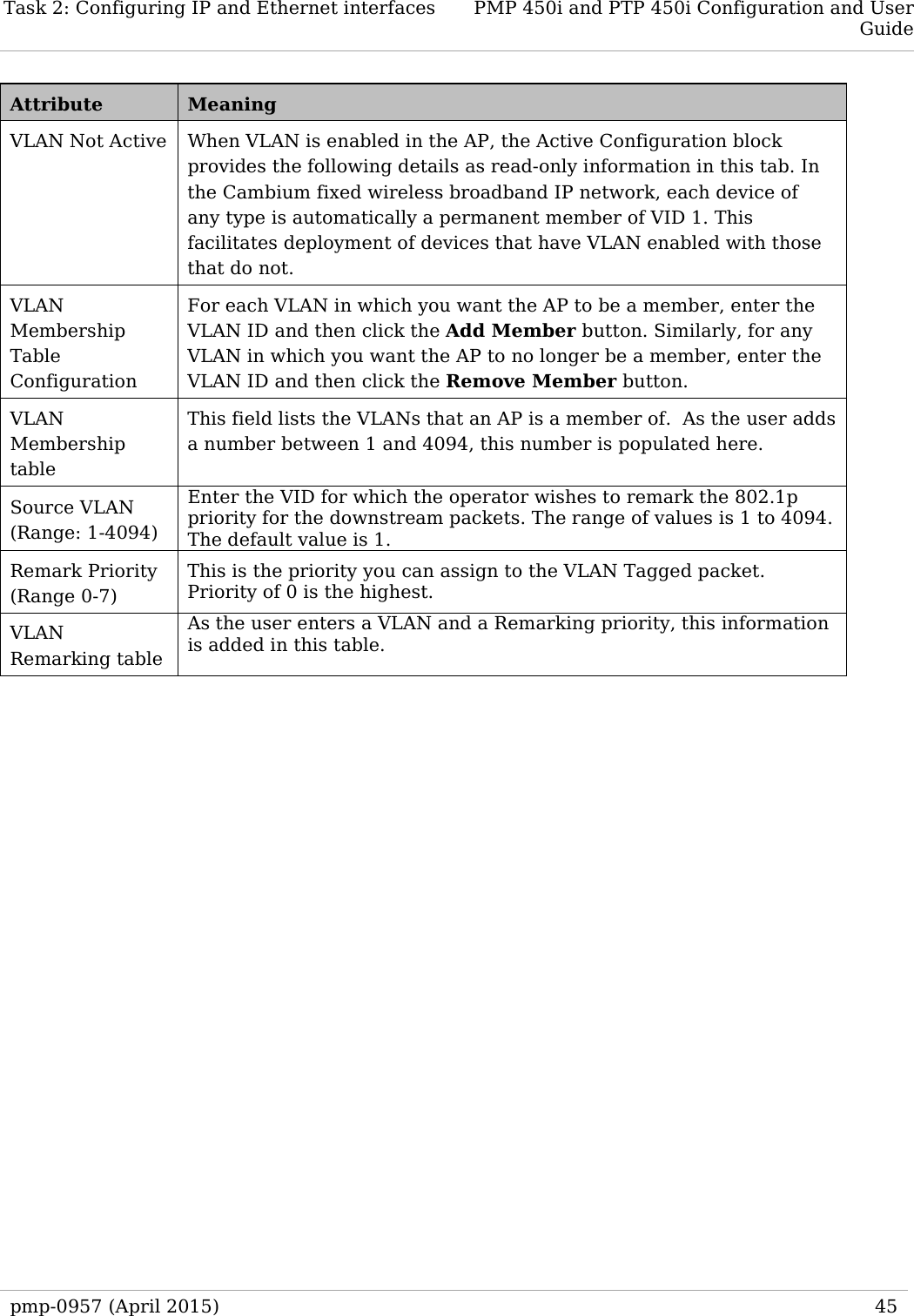
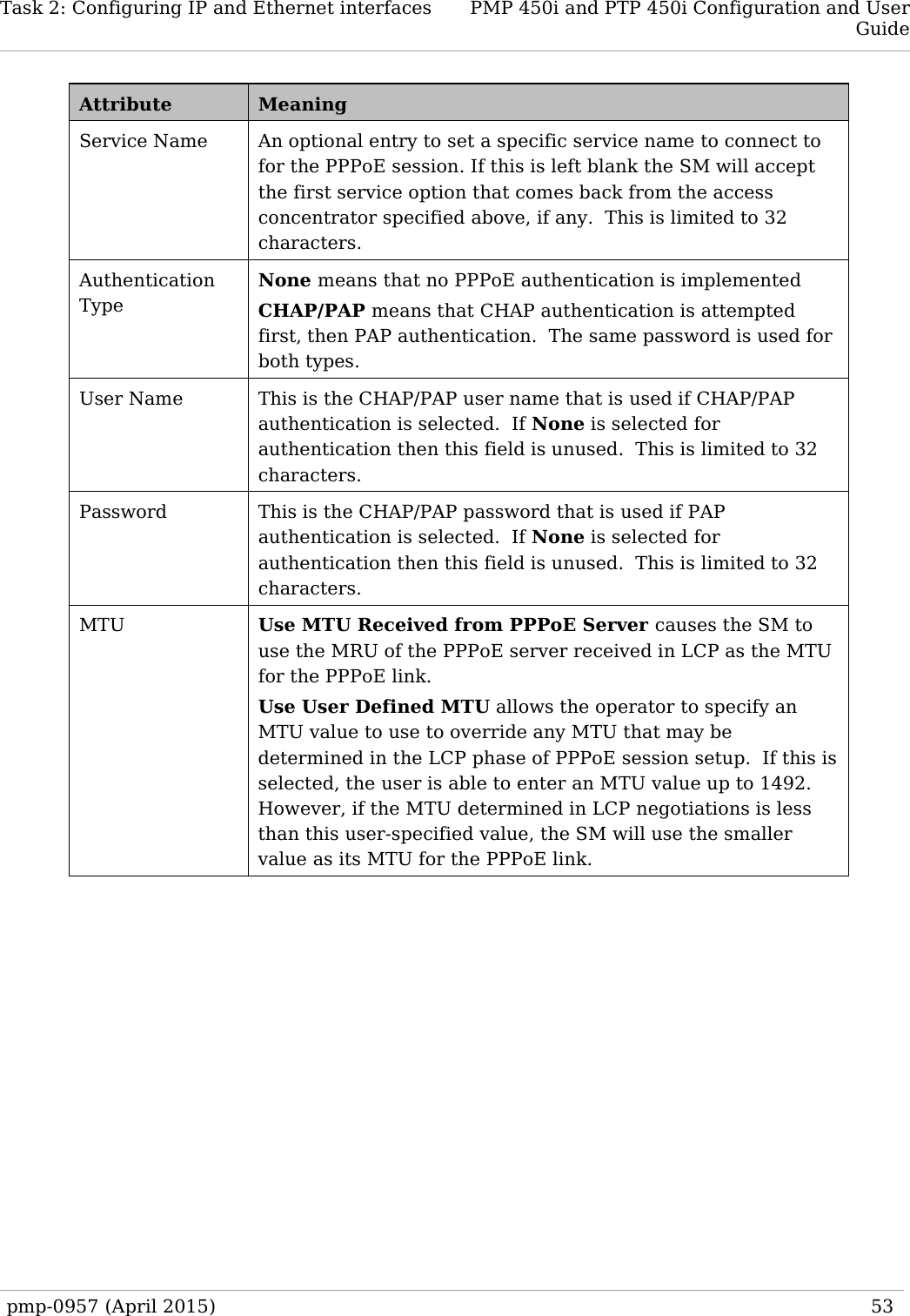
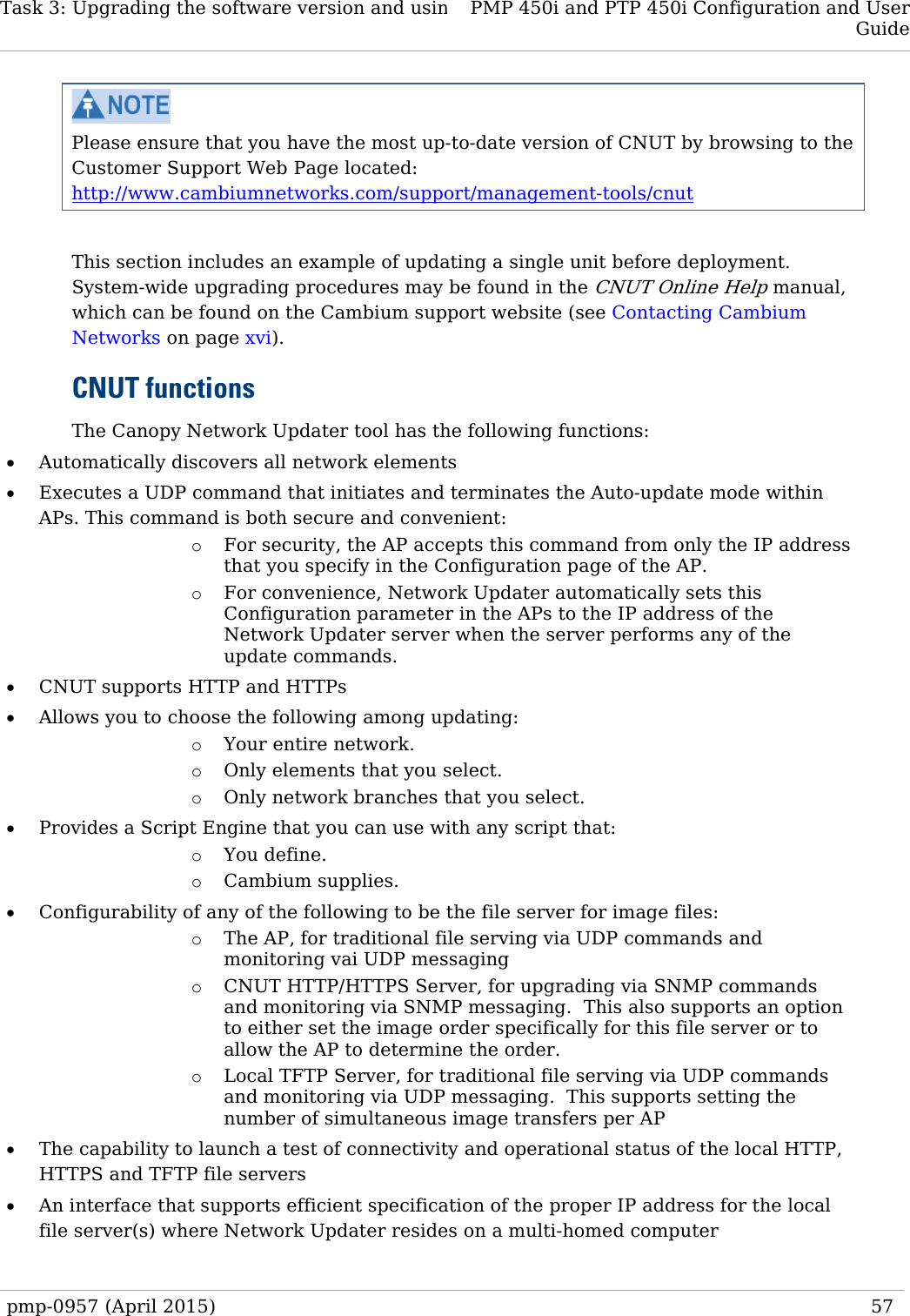
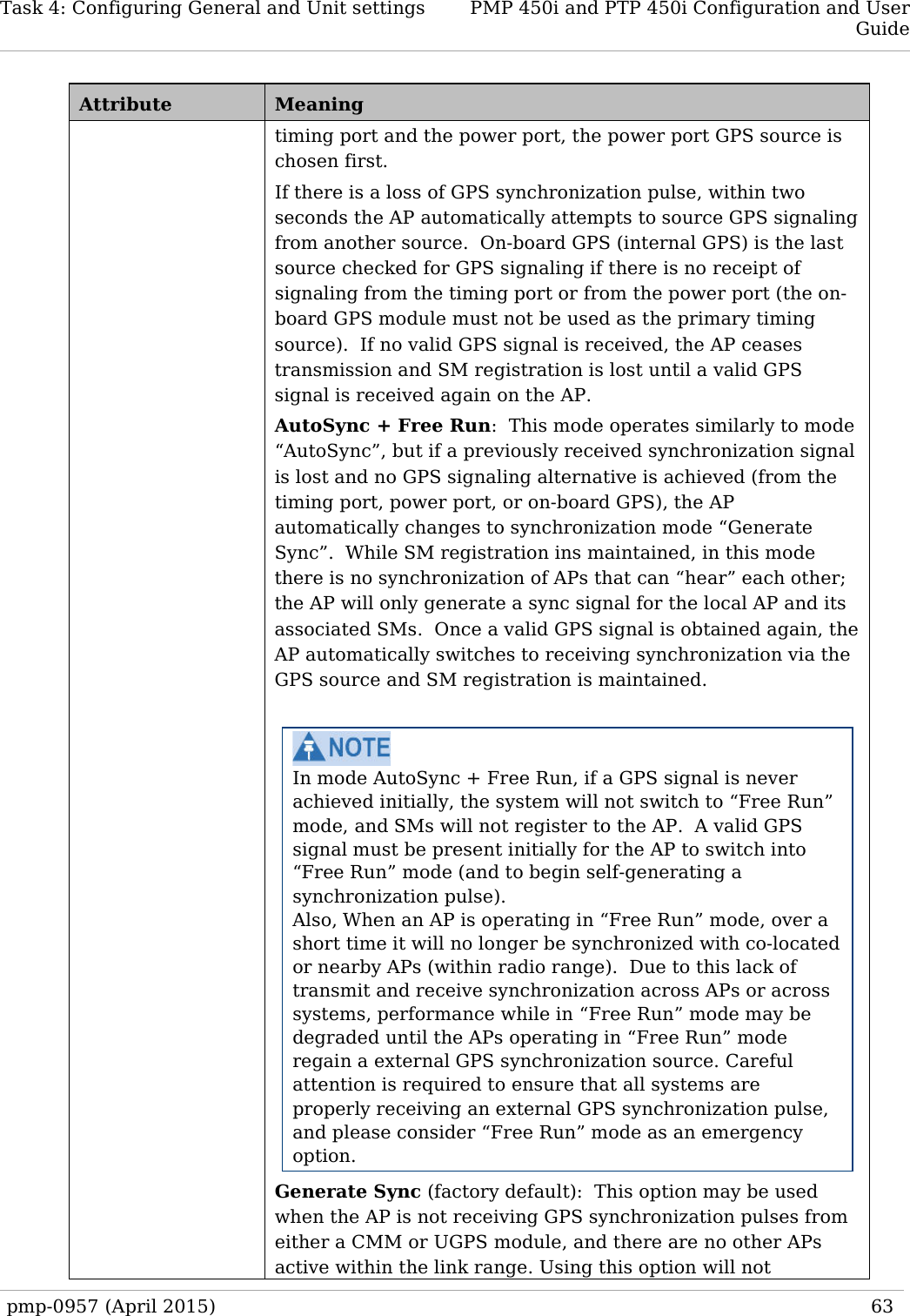
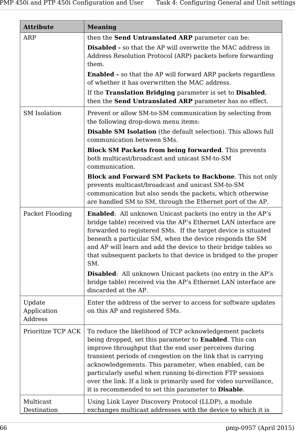
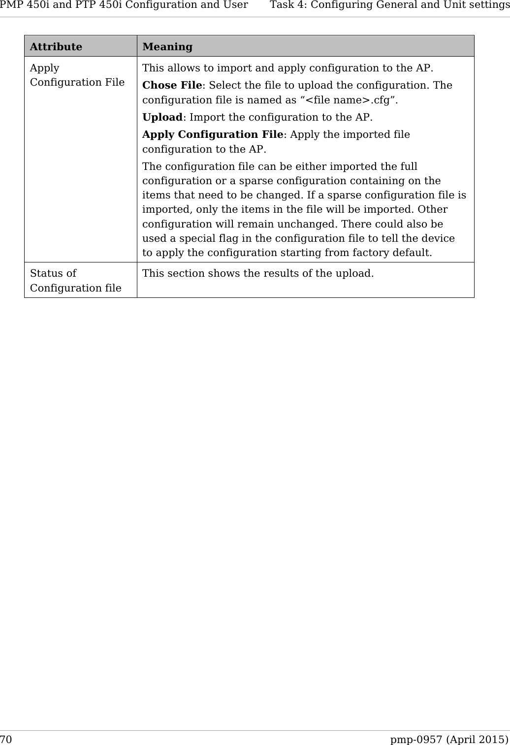
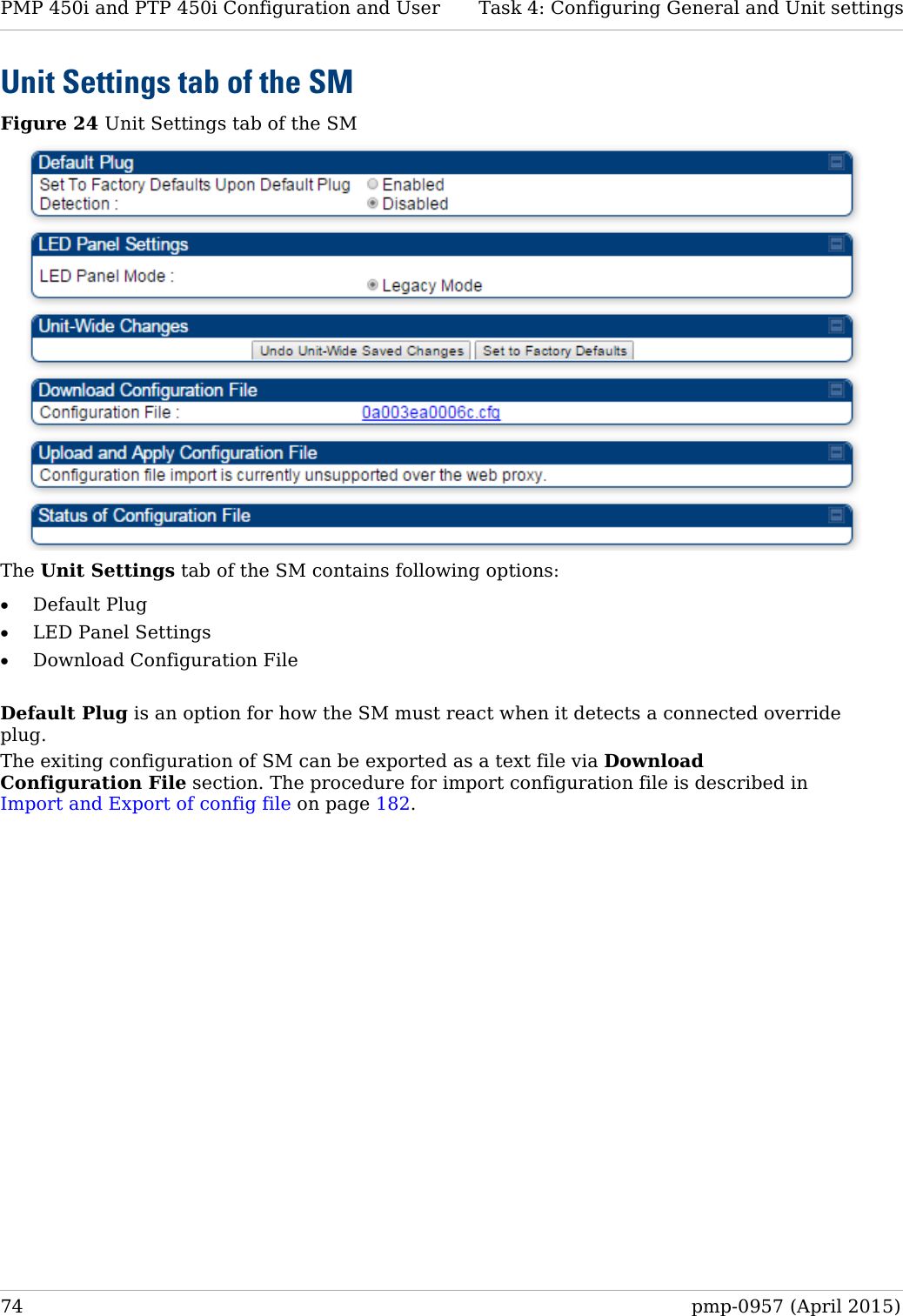
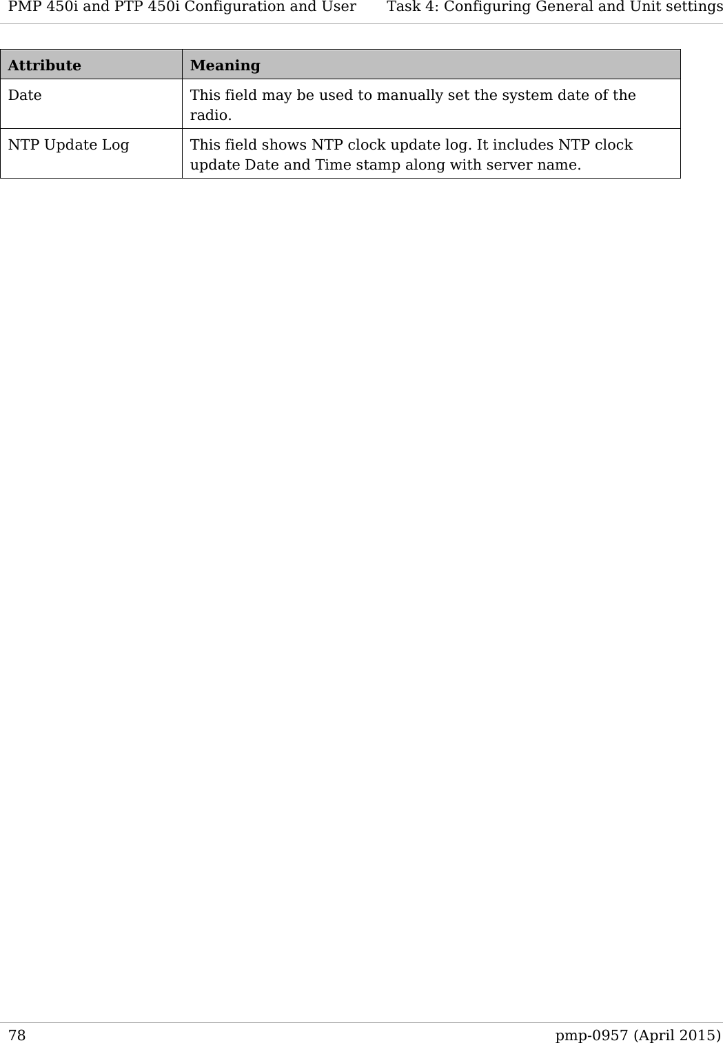
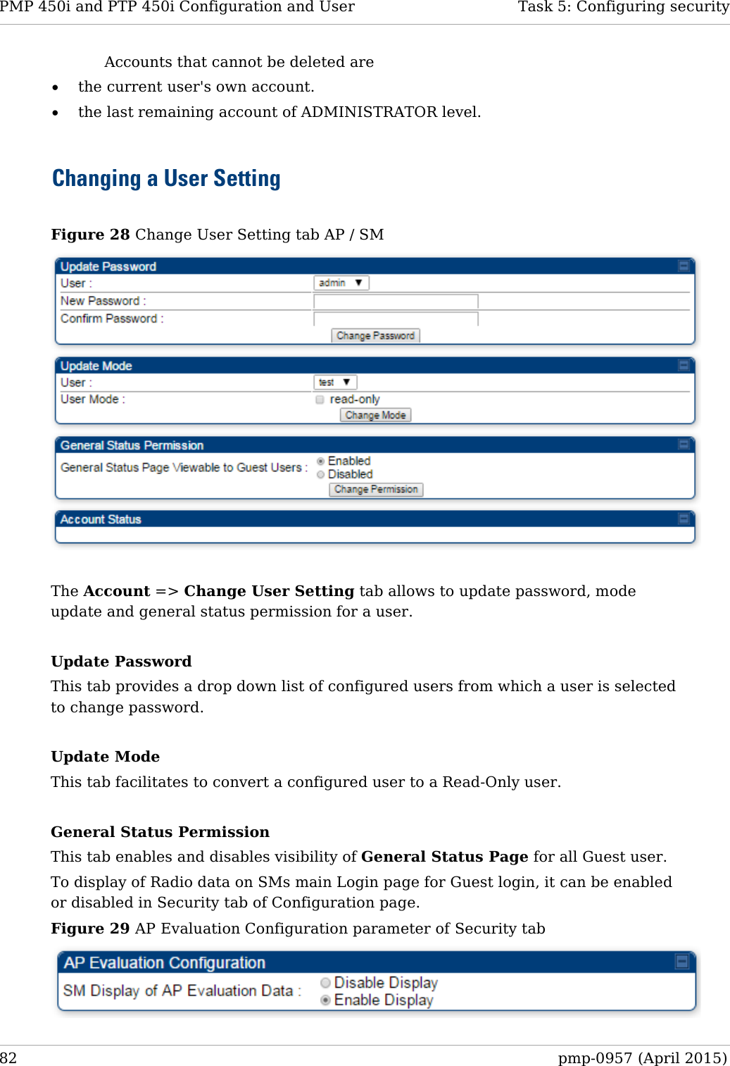
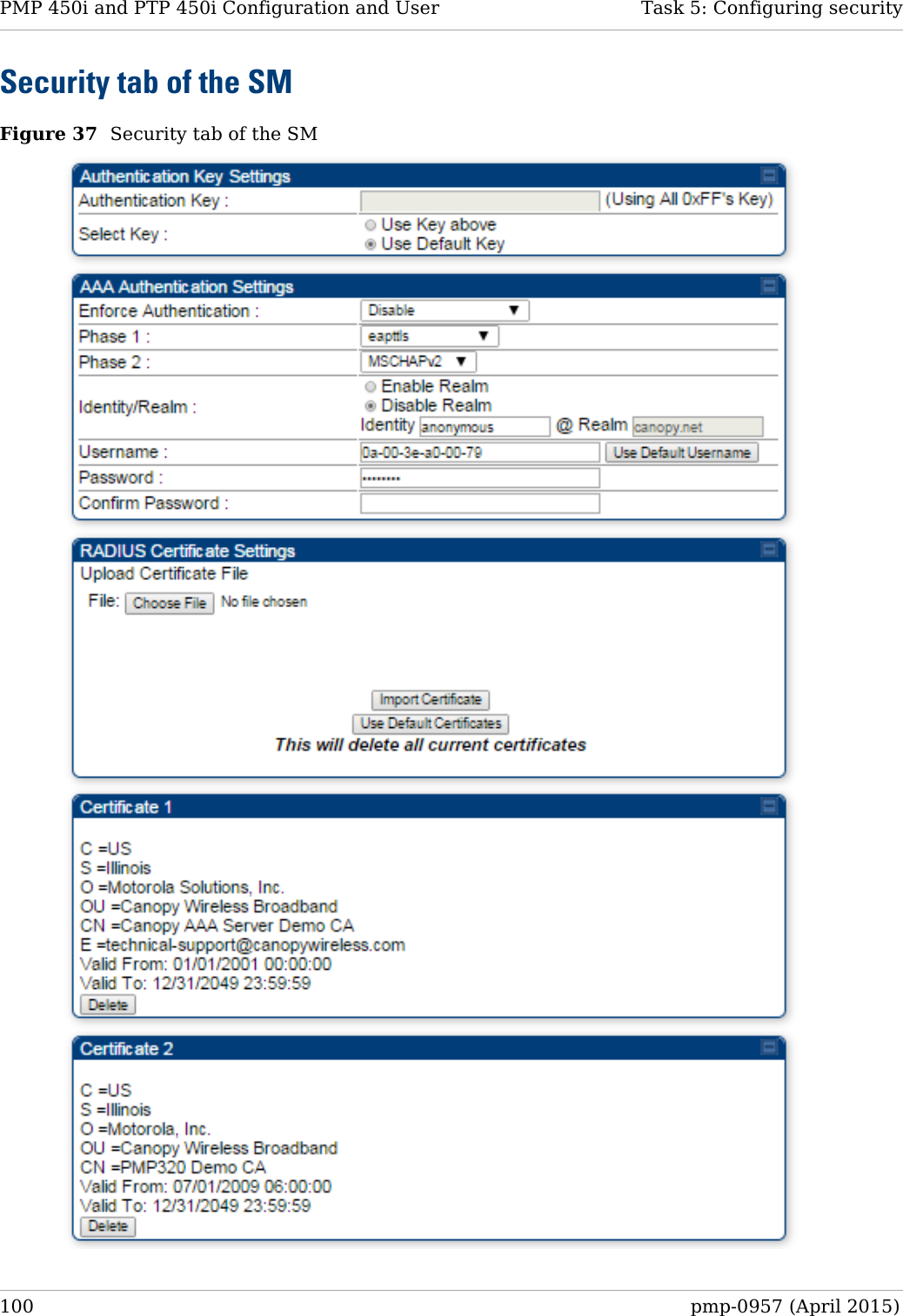
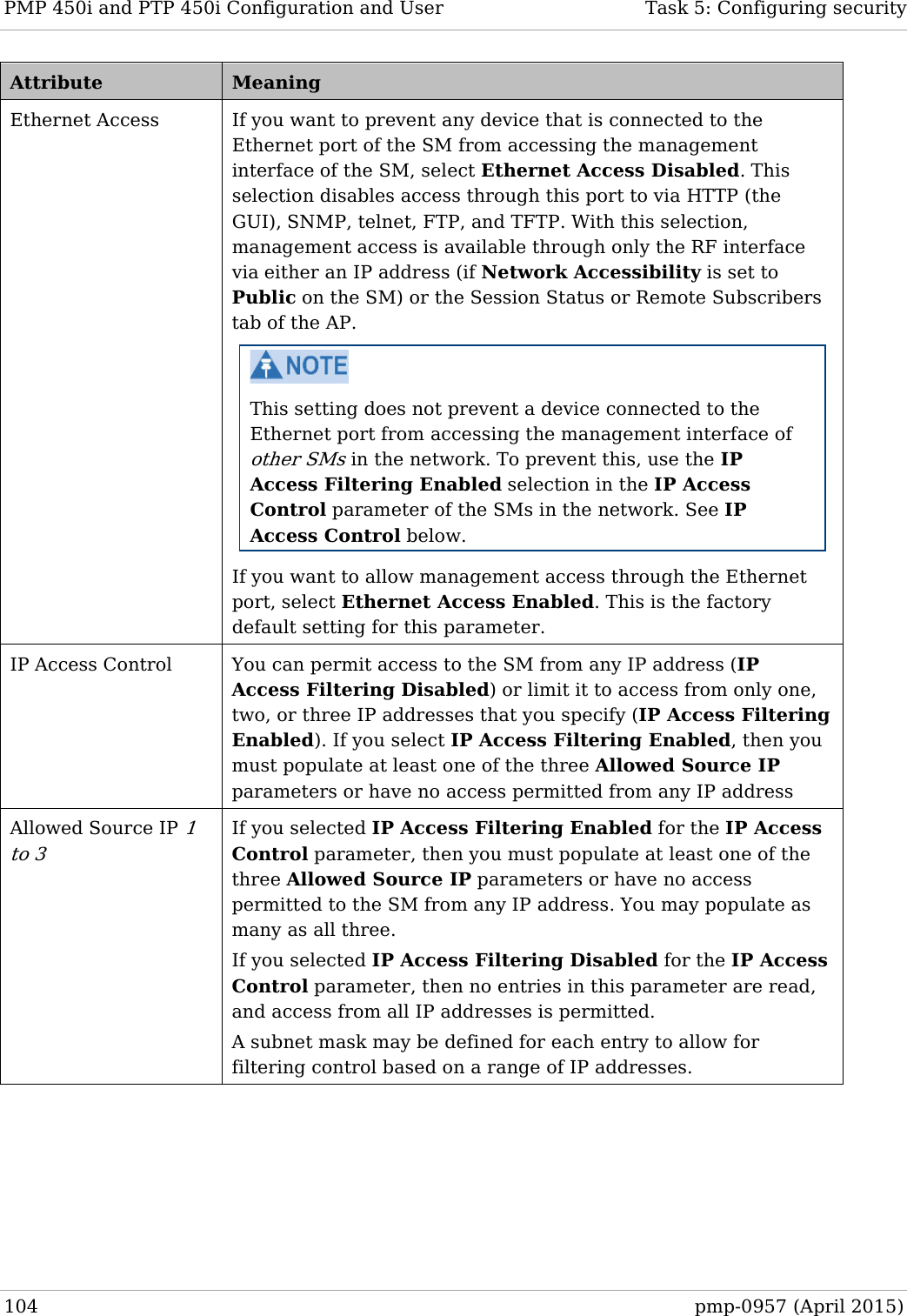
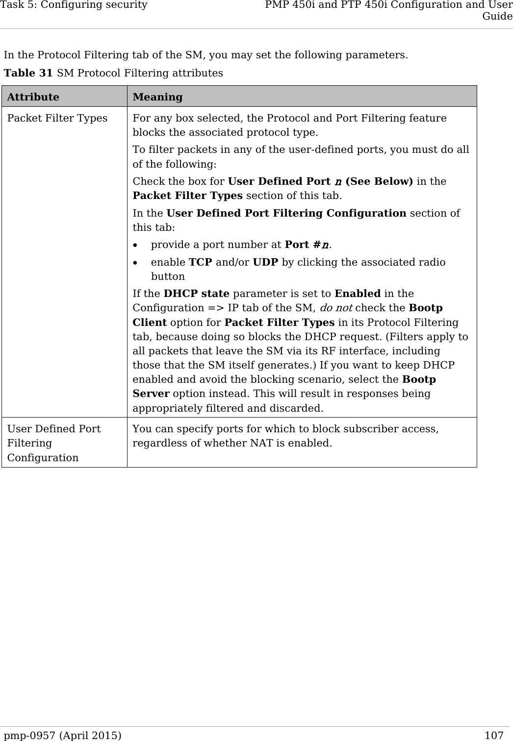
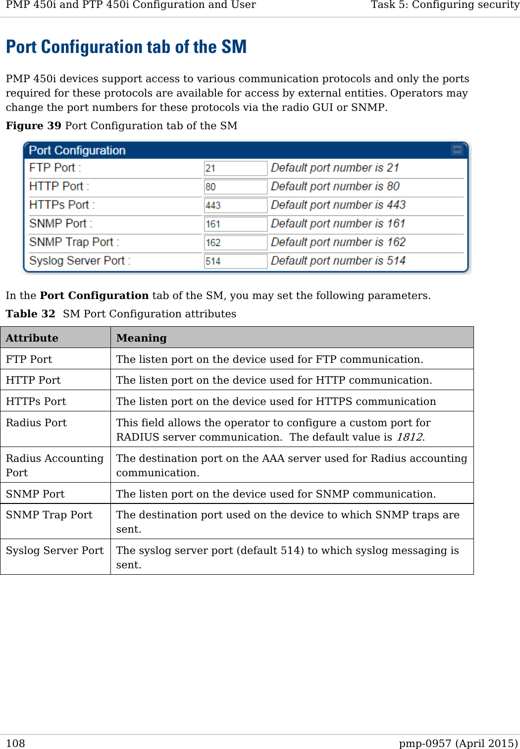
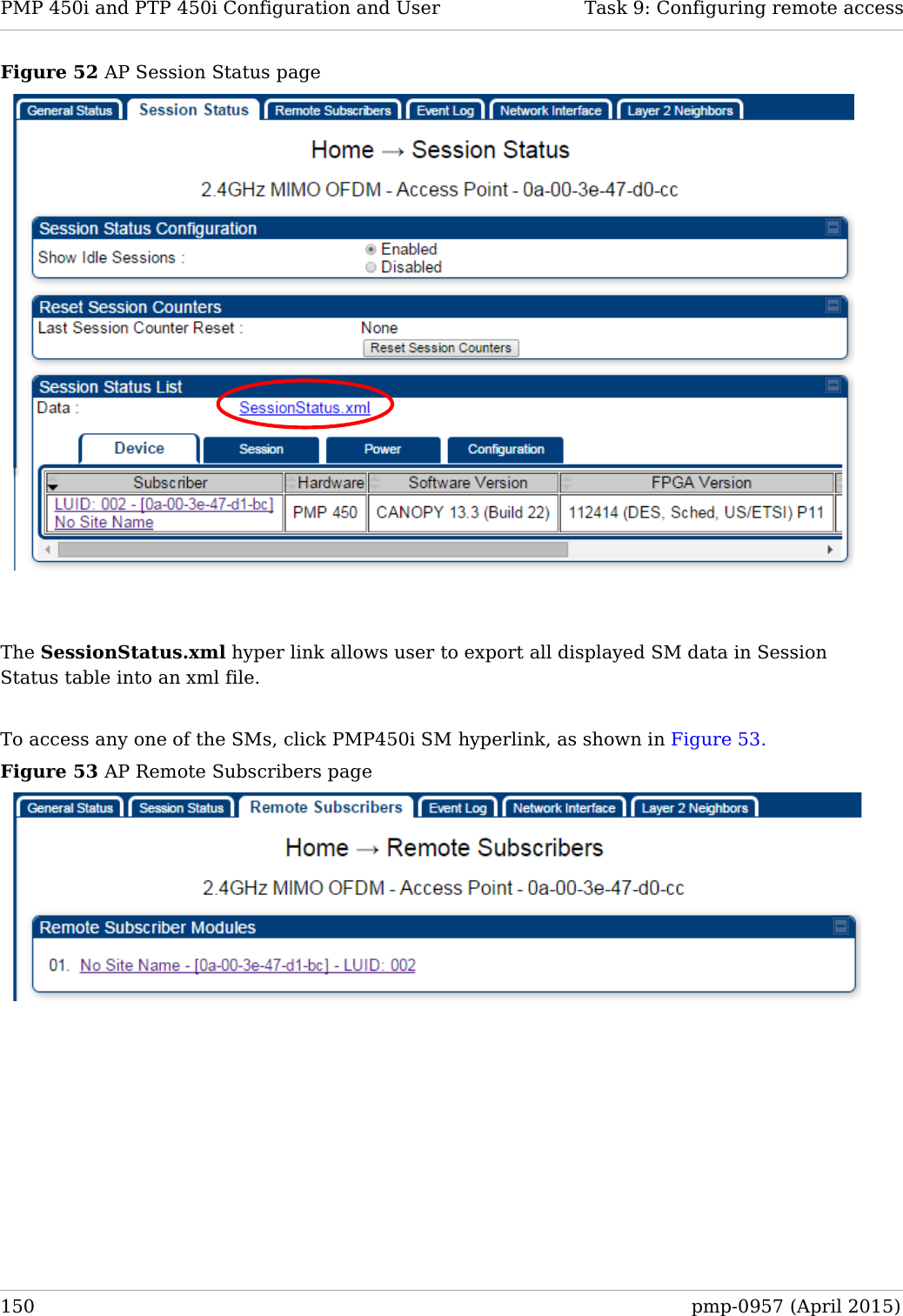
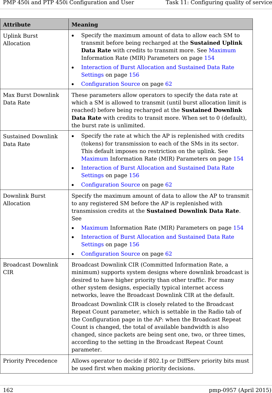
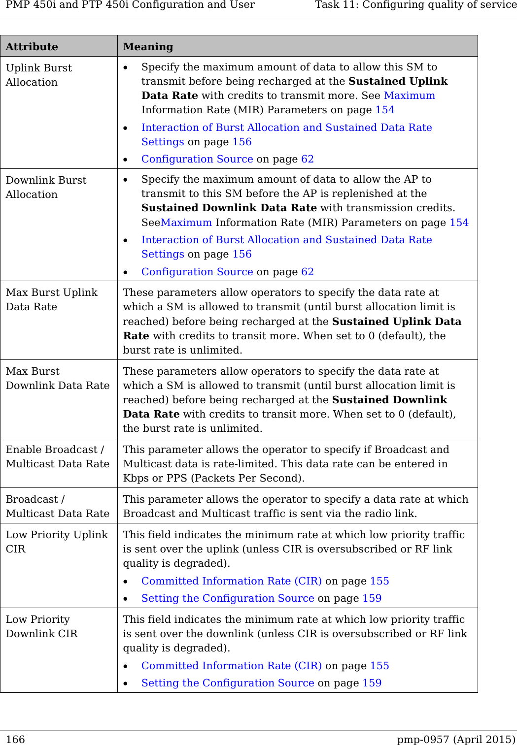
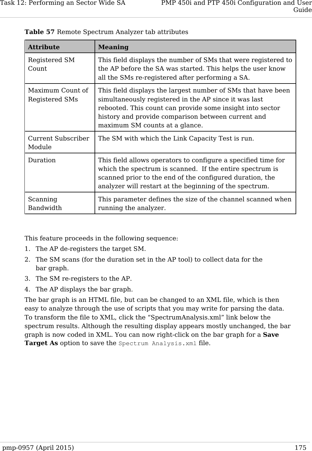
![PMP 450i and PTP 450i Configuration and User Task 5: Configuring security In the Protocol Filtering tab of the AP, you may set the following parameters. Table 28 AP Protocol Filtering attributes Attribute Meaning Packet Filter Types For any box selected, the Protocol and Port Filtering feature blocks the associated protocol type. To filter packets in any of the user-defined ports, you must do all of the following: Check the box for User Defined Port n (See Below) in the Packet Filter Types section of this tab. In the User Defined Port Filtering Configuration section of this tab: • provide a port number at Port #n. • enable TCP and/or UDP by clicking the associated radio button Filter Direction Operators may choose to filter upstream (uplink) RF packets or downstream (downlink) RF packets. User Defined Port Filtering Configuration You can specify ports for which to block subscriber access, regardless of whether NAT is enabled. RF Telnet Access RF Telnet Access restricts Telnet access to the AP from a device situated below a network SM (downstream from the AP). This is a security enhancement to restrict RF-interface sourced AP access specifically to the LAN1 IP address and LAN2 IP address (Radio Private Address, typically 192.168.101.[LUID]). This restriction disallows unauthorized users from running Telnet commands on the AP that can change AP configuration or modifying network-critical components such as routing and ARP tables. PPPoE PADI Downlink Forwarding Enabled: the AP allows downstream and upstream transmission of PPPoE PADI packets. By default, PPPoE PADI Downlink Forwarding is set to “Enabled”. Disabled: the AP disallows PPPoE PADI packets from entering the Ethernet interface and exiting the RF interface (downstream to the SM). PPPoE PADI packets are still allowed to enter the AP’s RF interface and exit the AP’s Ethernet interface (upstream). 98 pmp-0957 (April 2015)](https://usermanual.wiki/Cambium-Networks/50450I.Installation-Guide/User-Guide-2619716-Page-120.png)
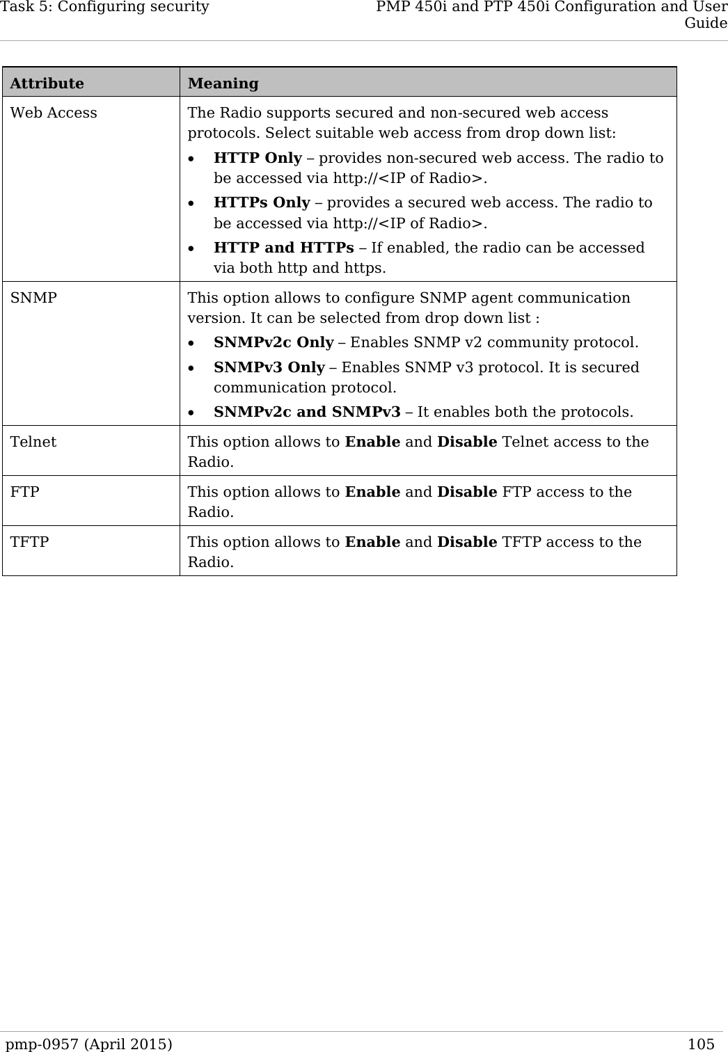


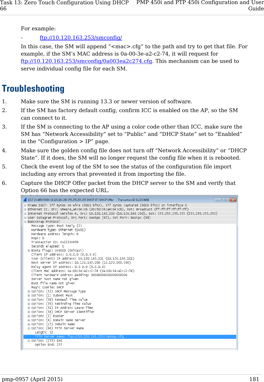
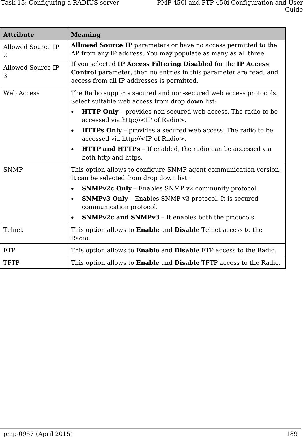
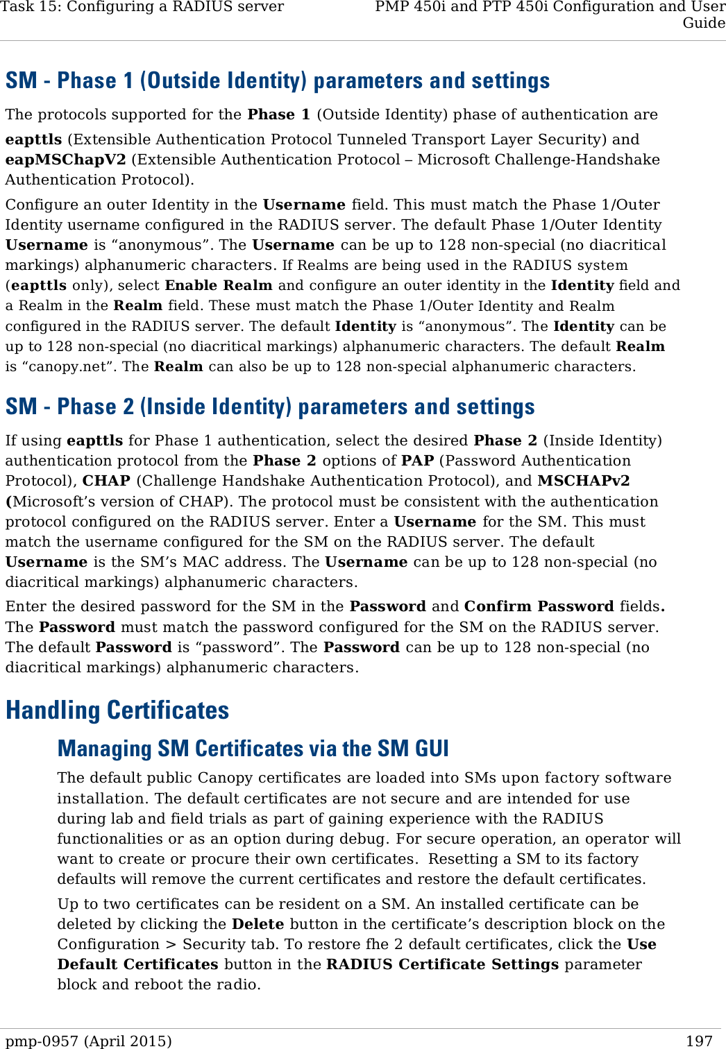
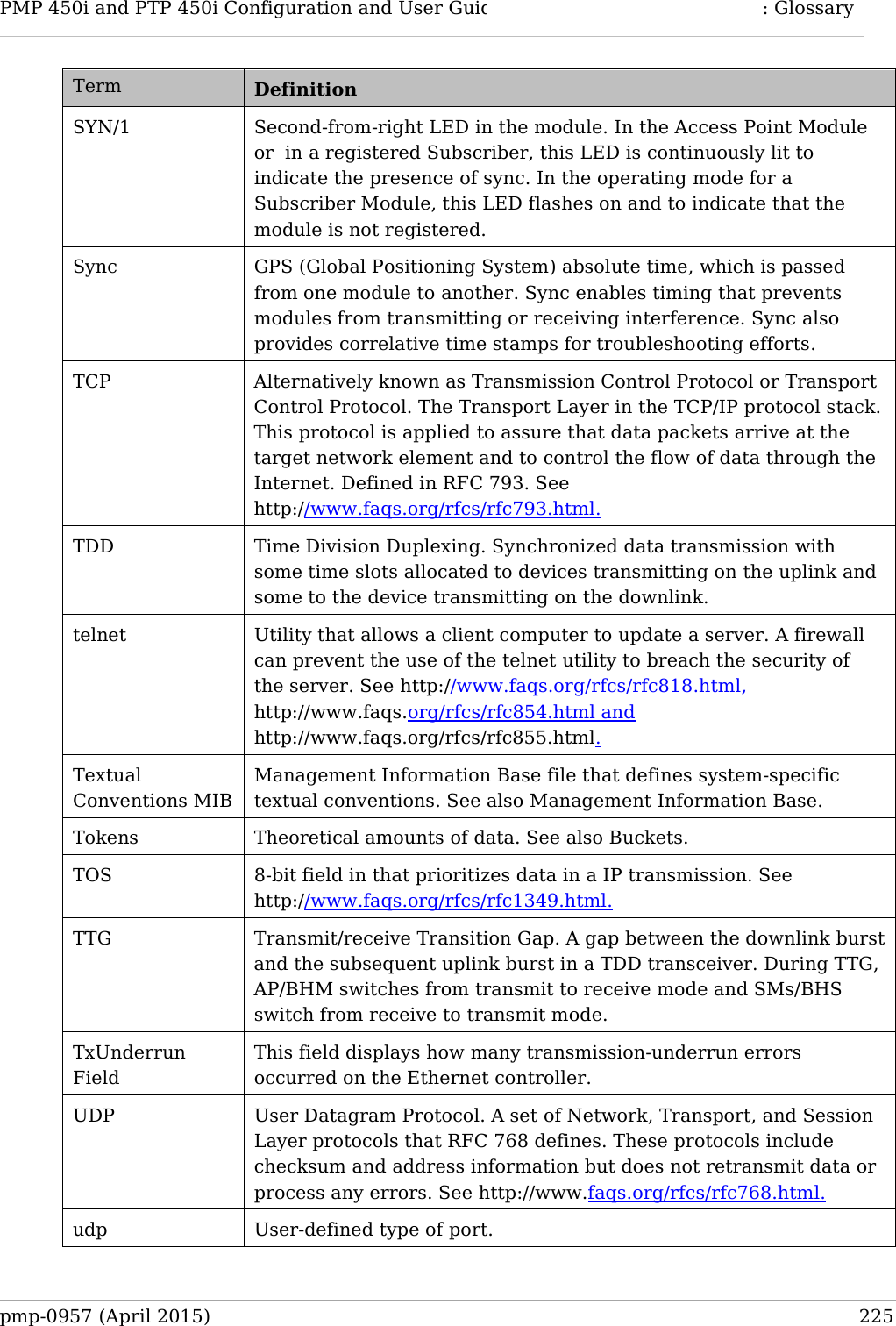
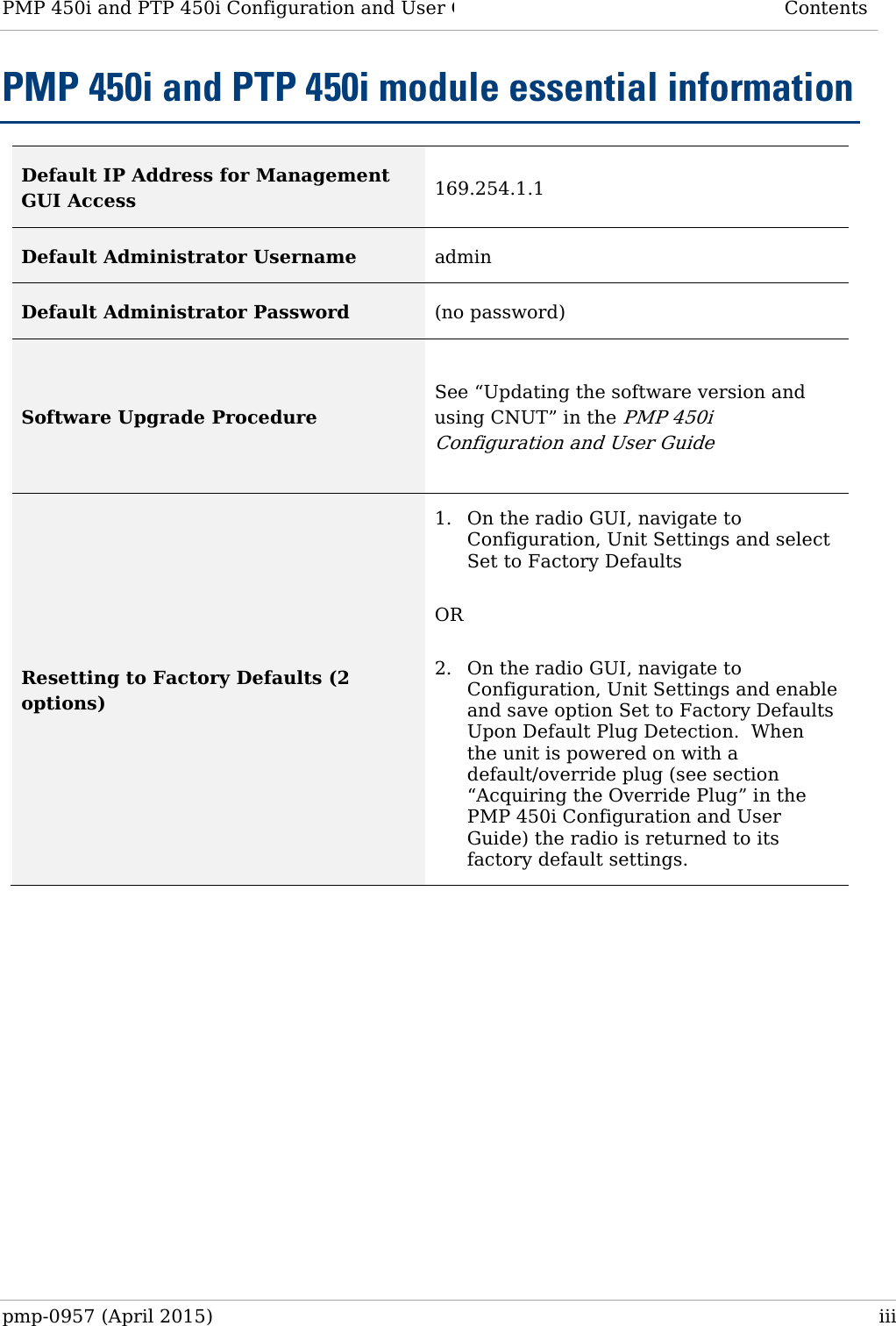
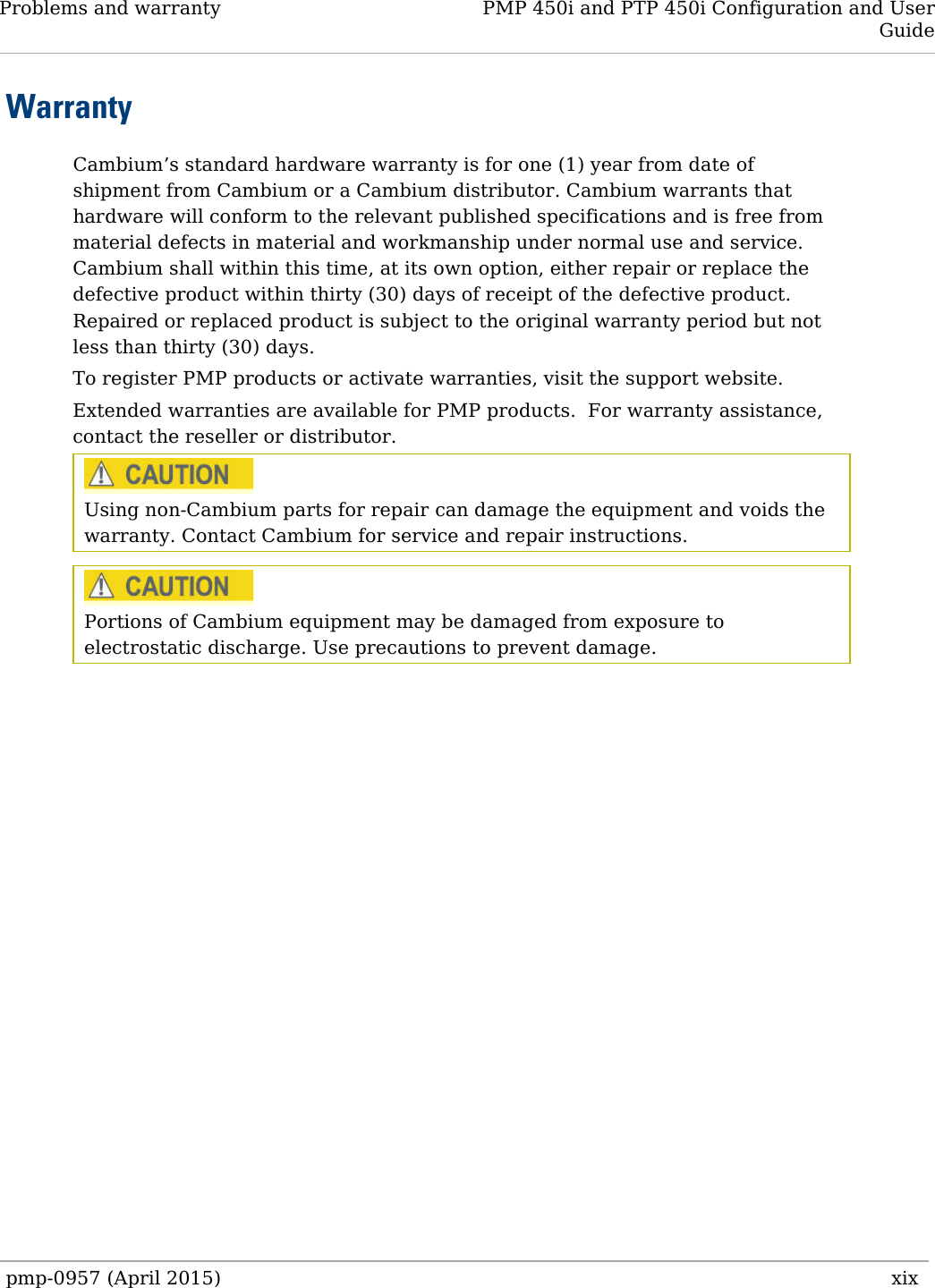
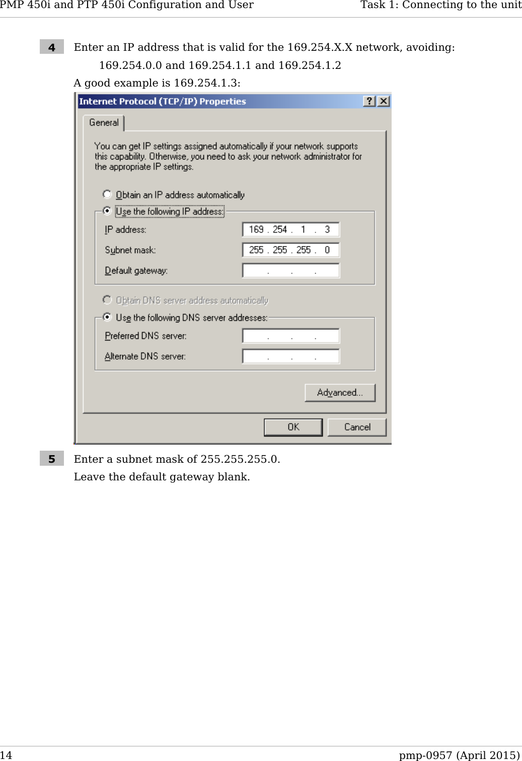
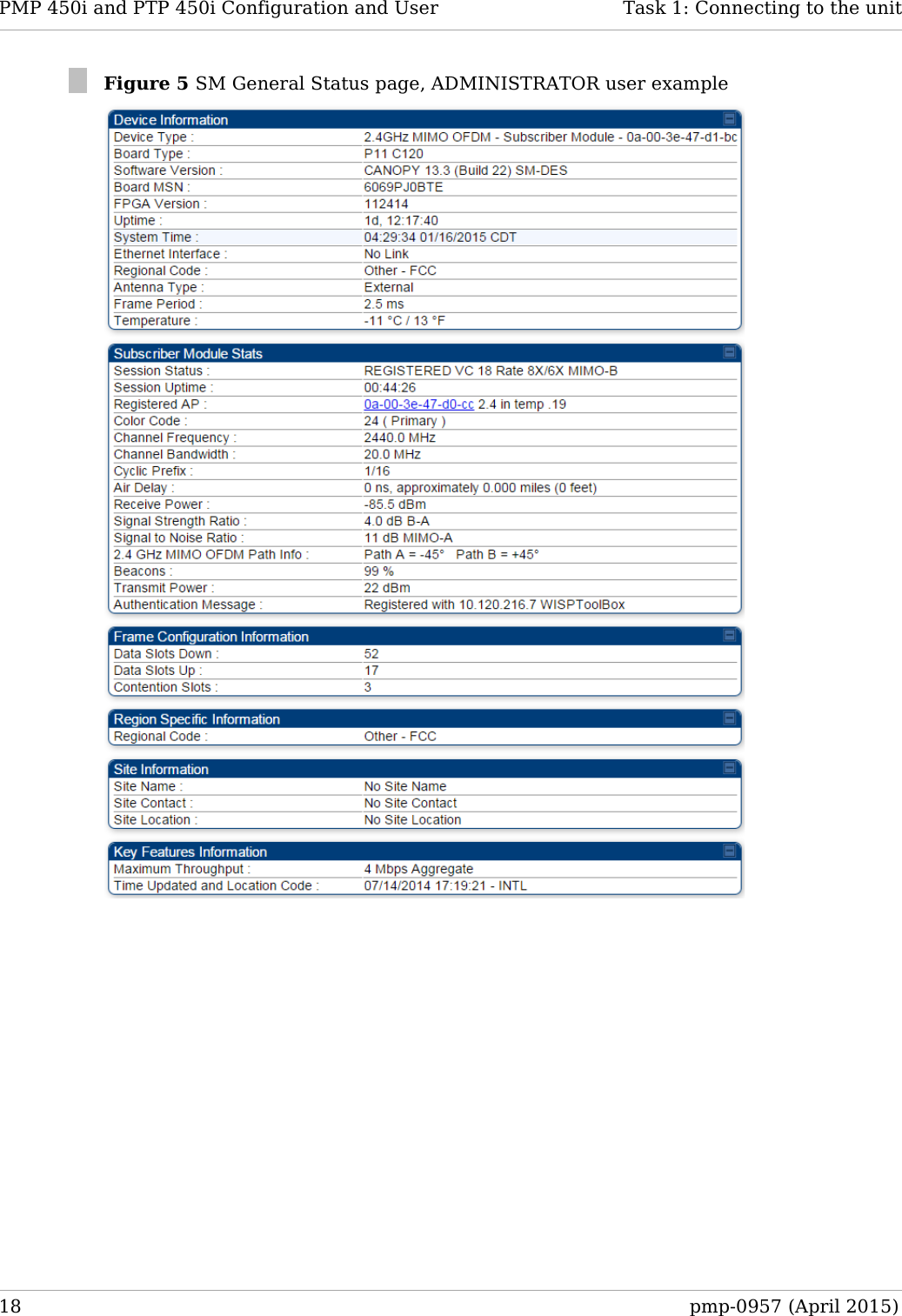
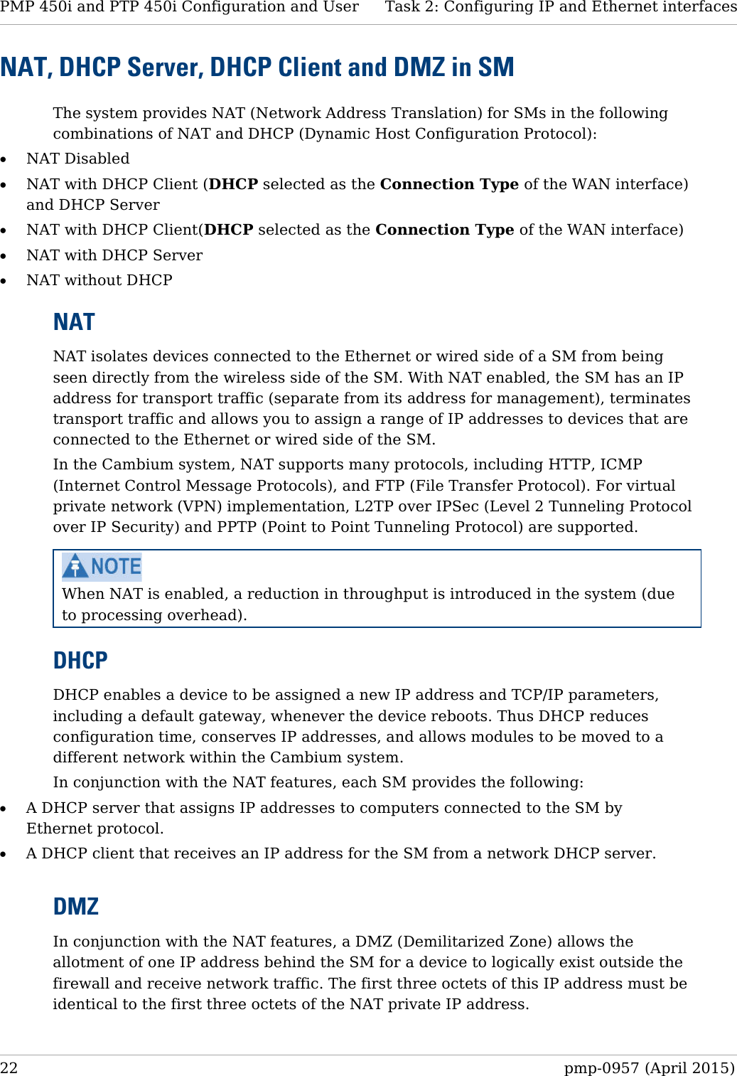
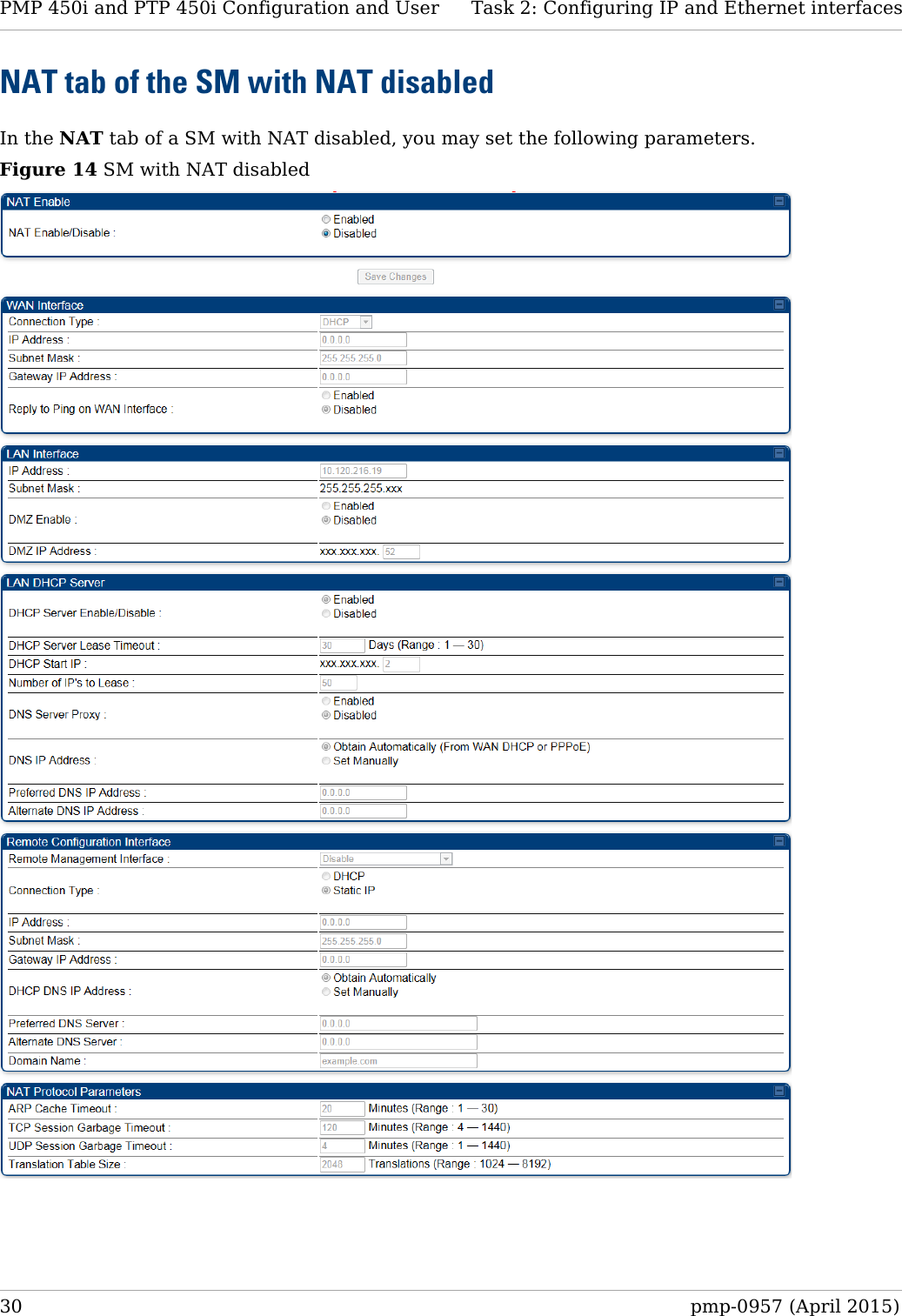
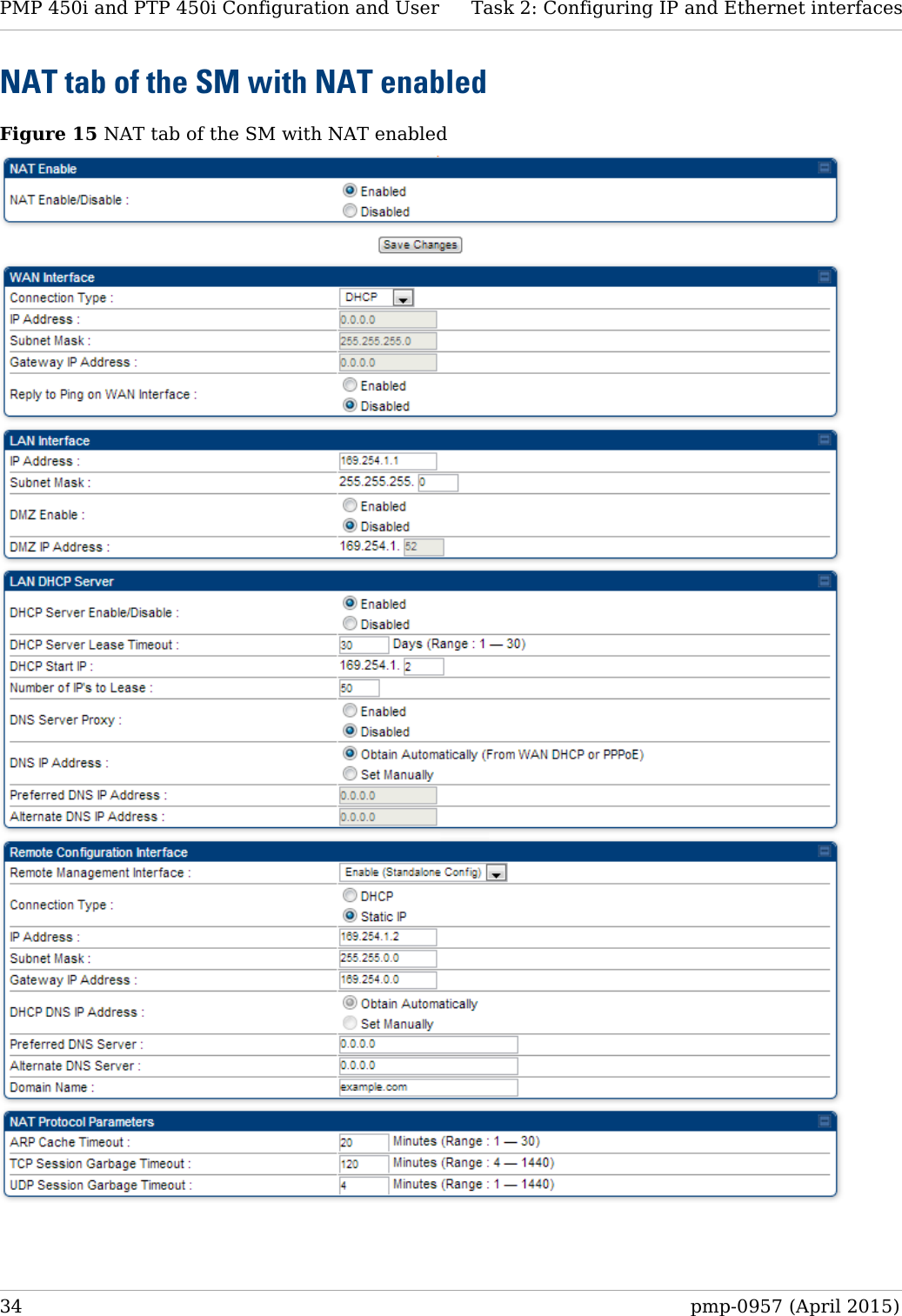
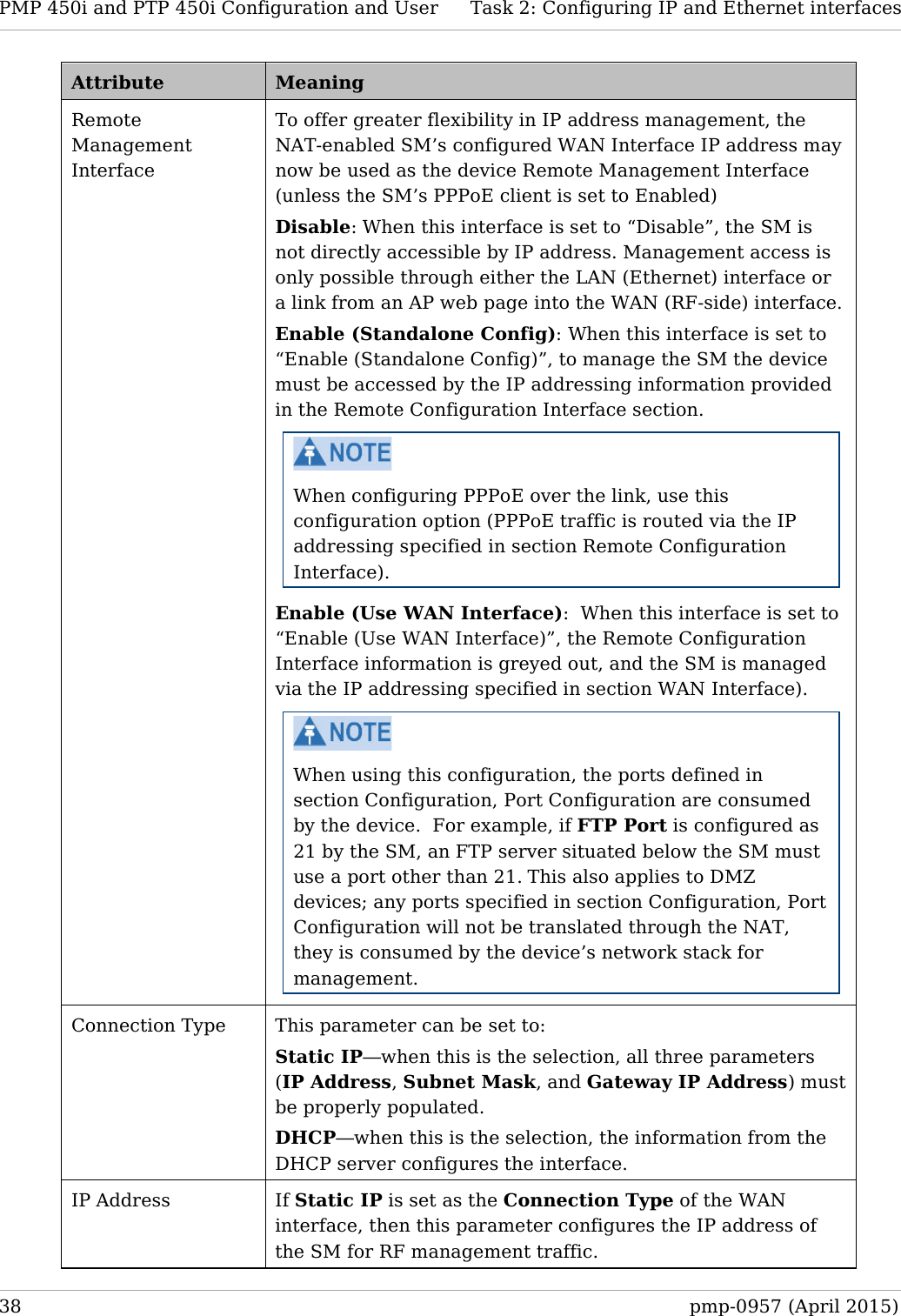
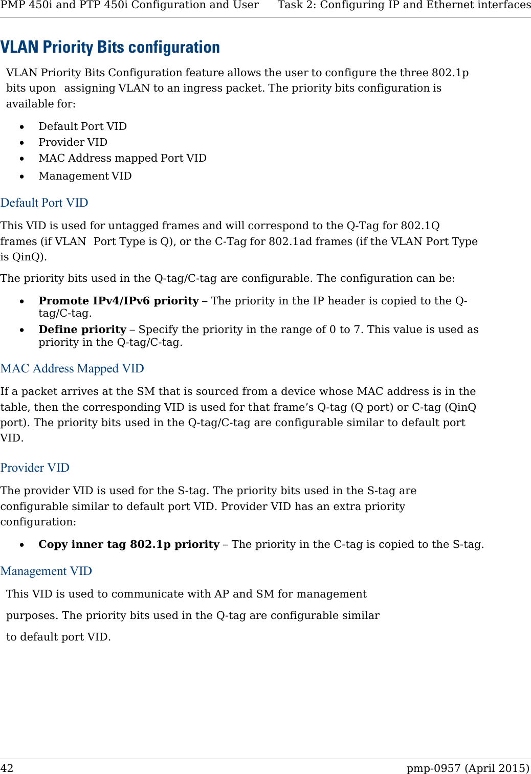
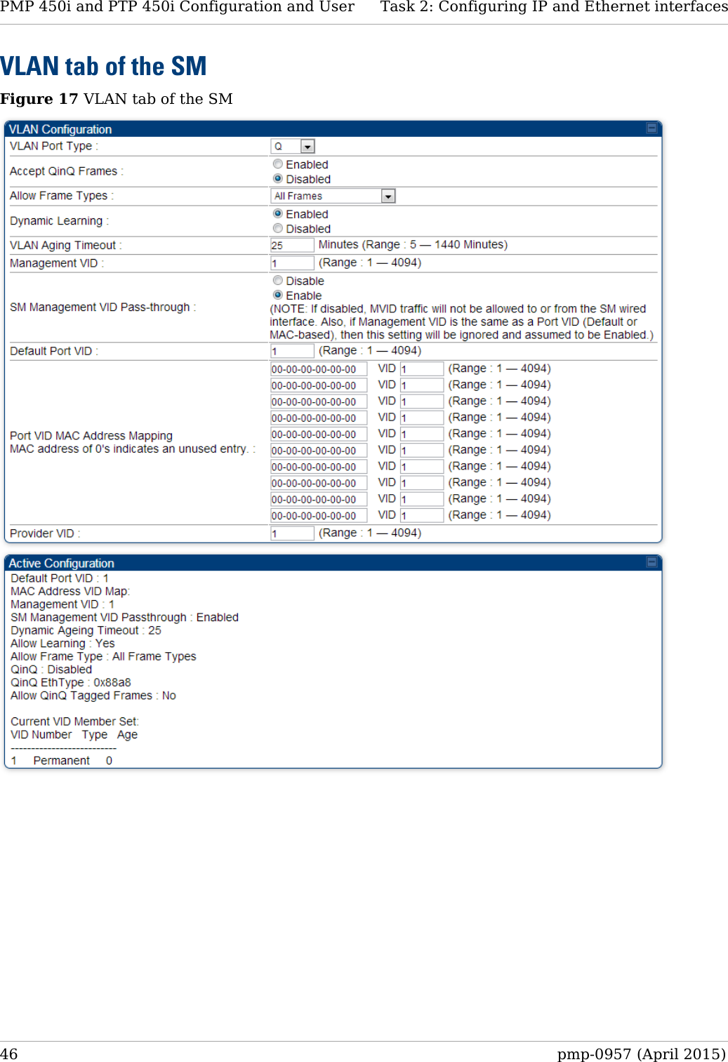
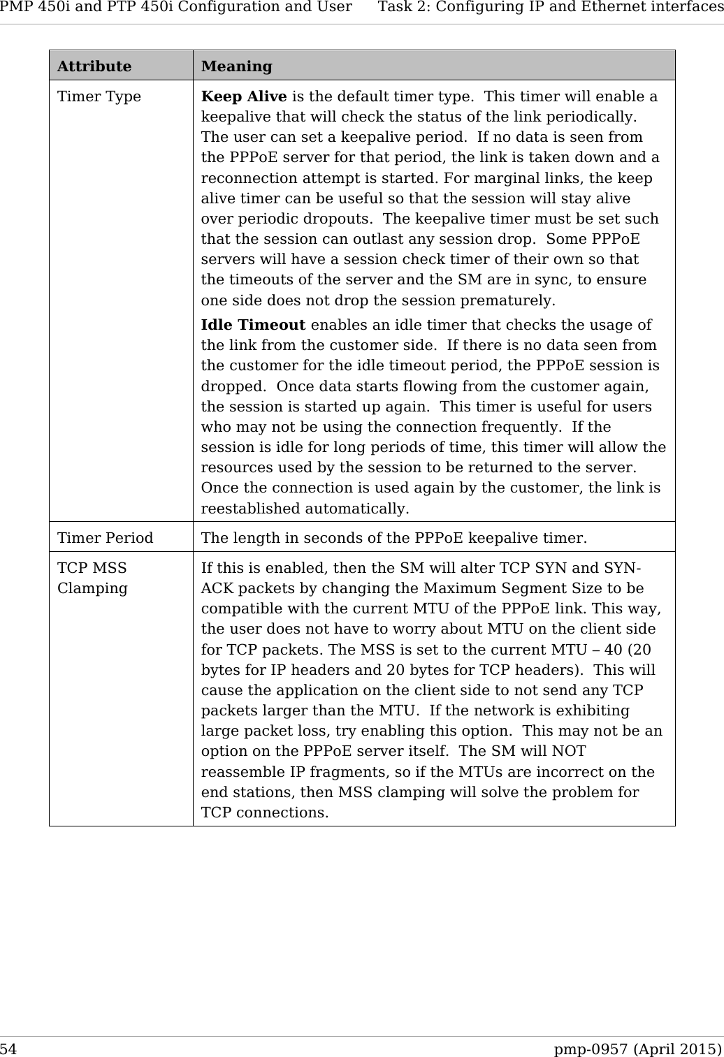
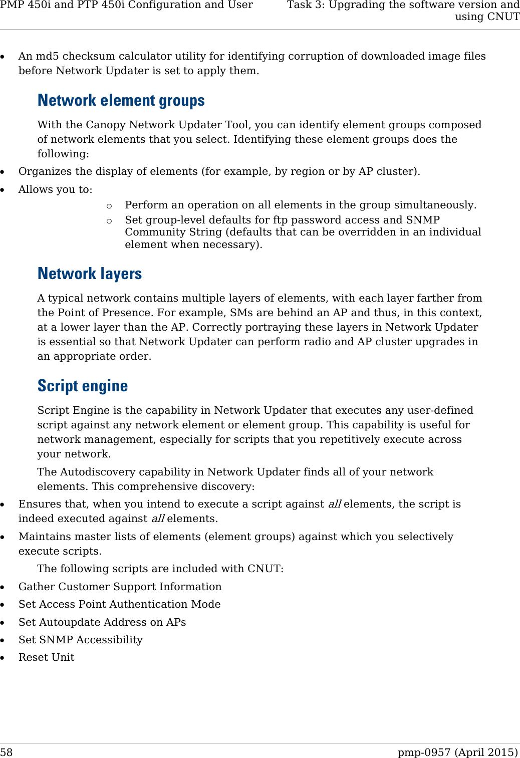
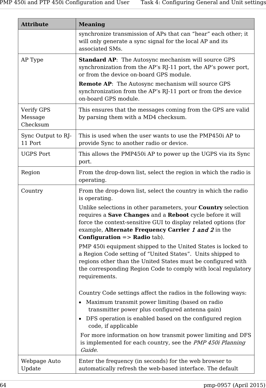
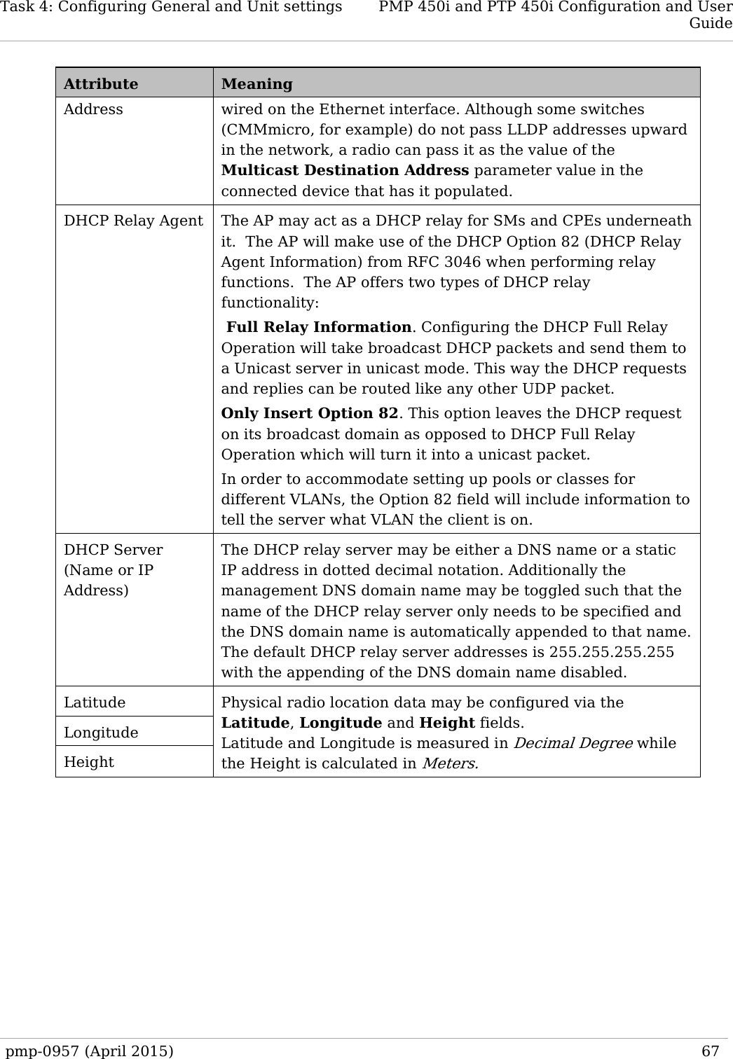
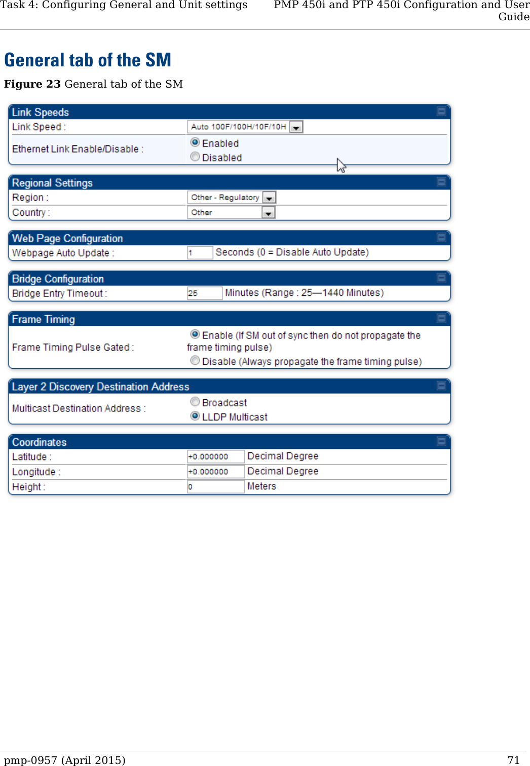
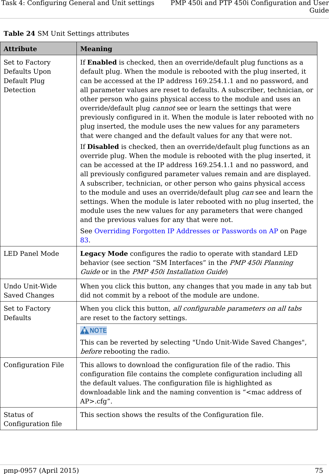
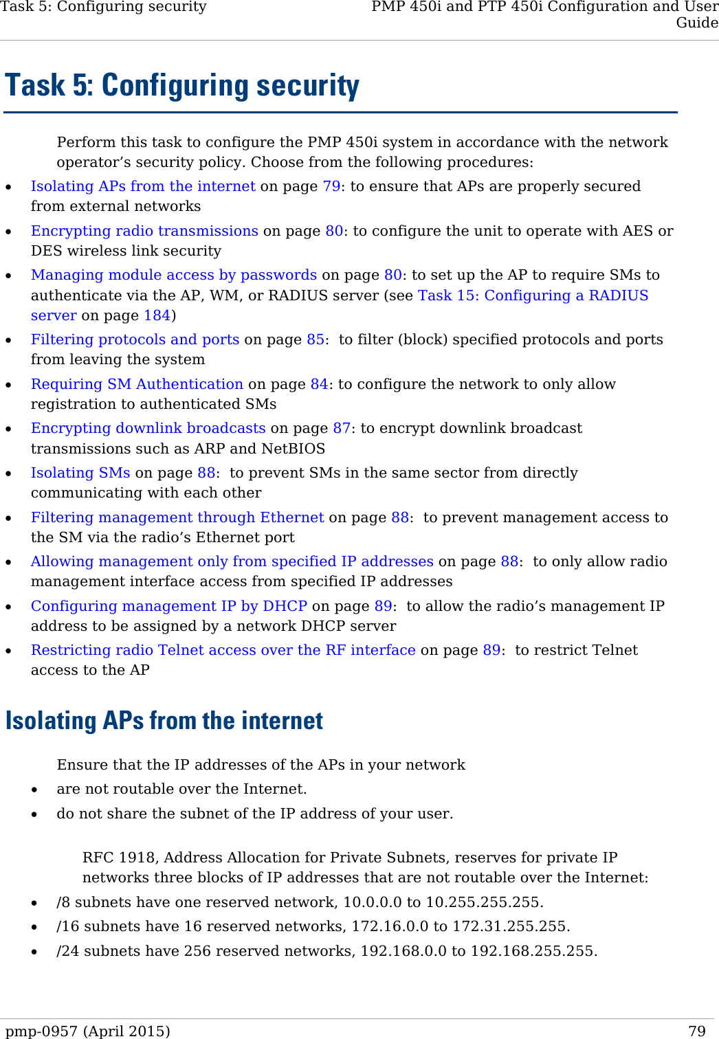
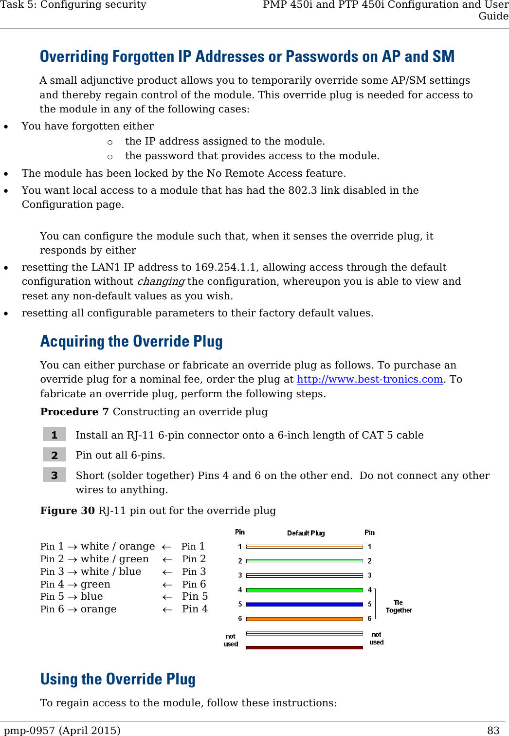
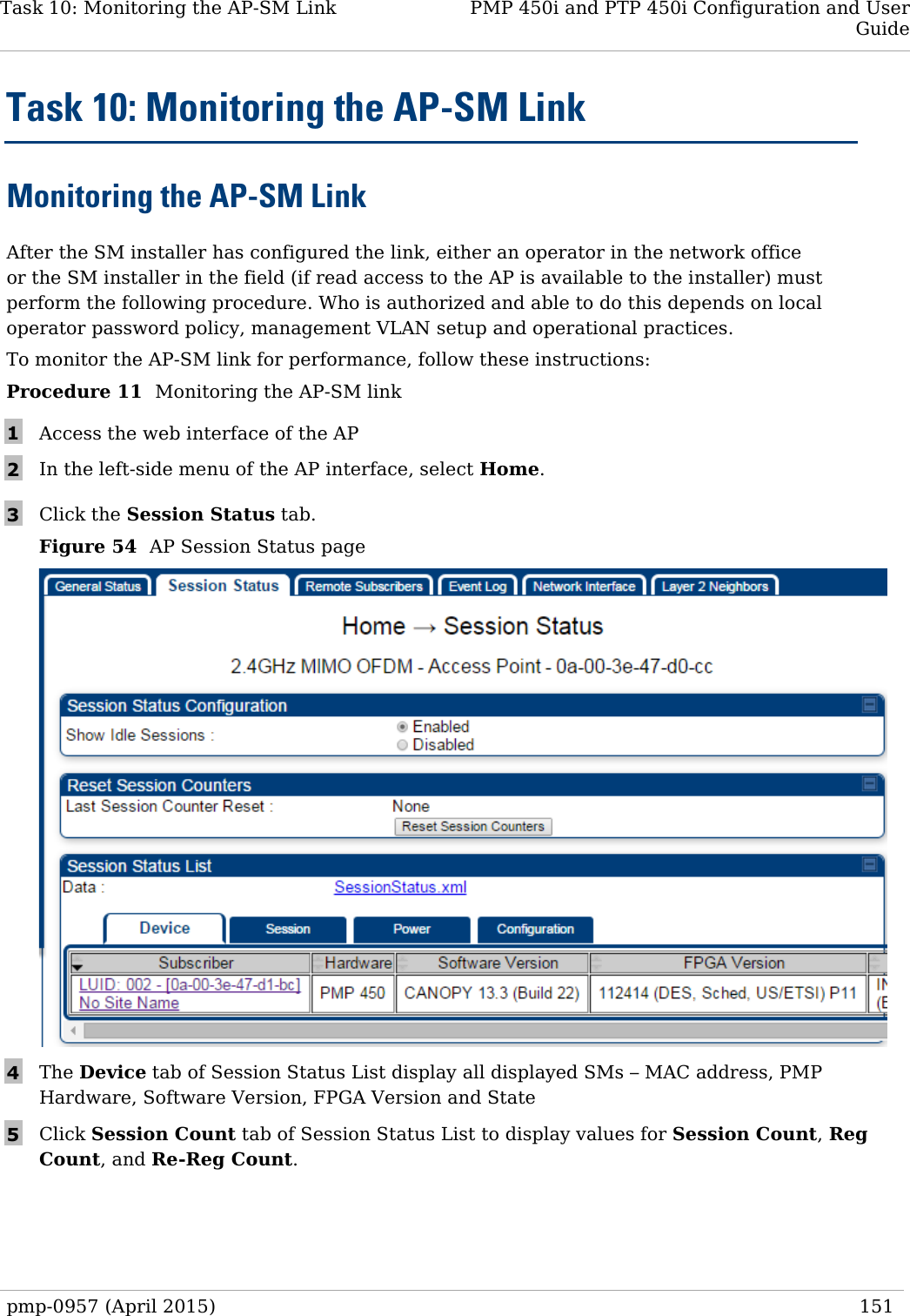
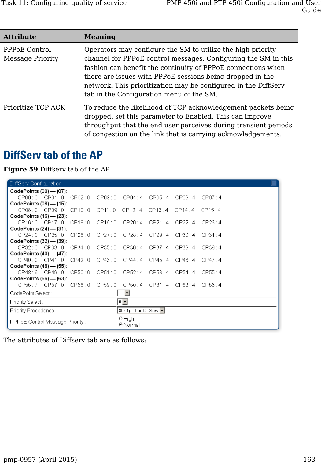
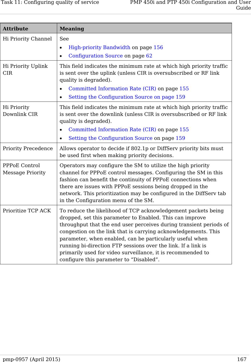
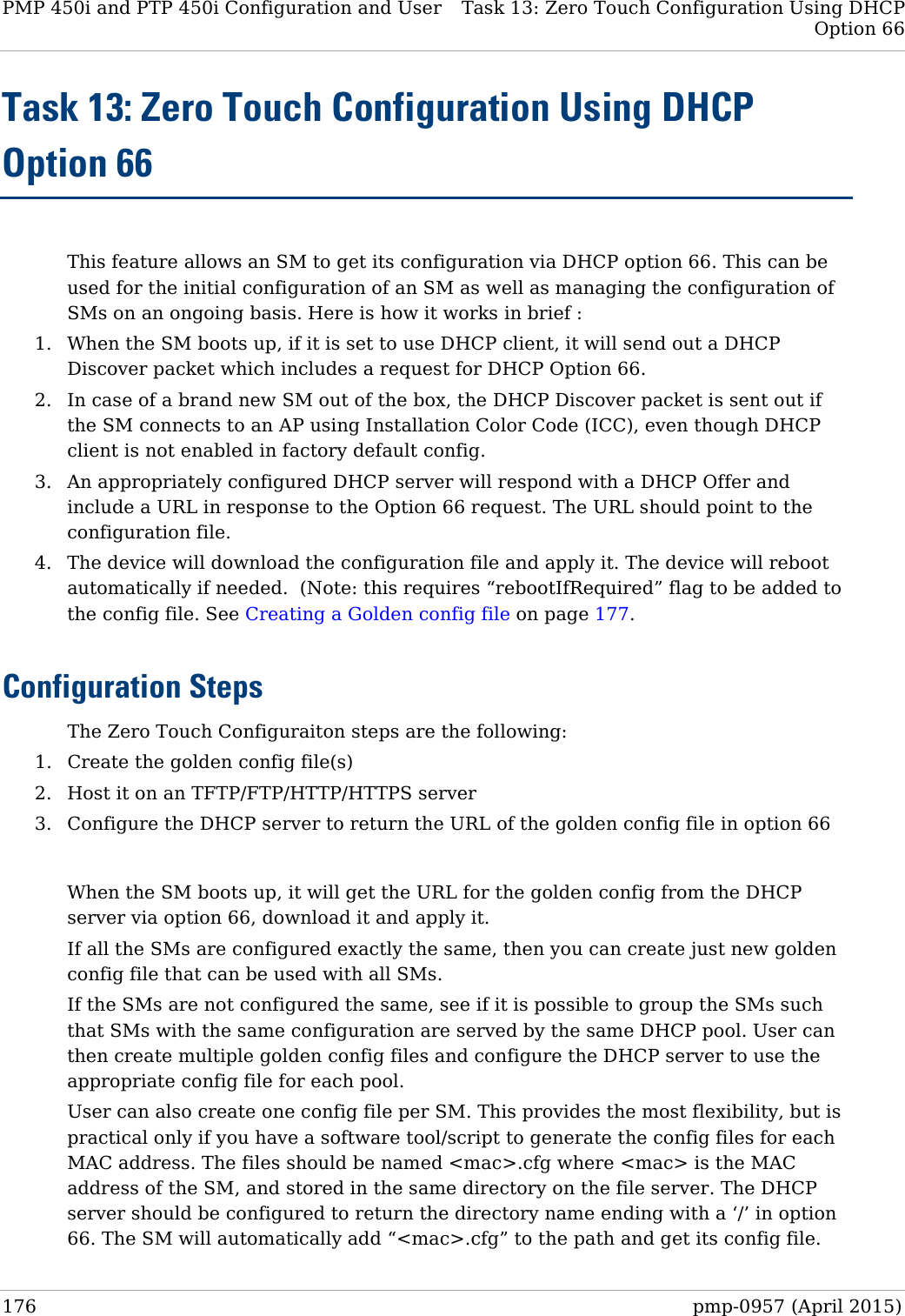
![Task 9: Configuring remote access PMP 450i and PTP 450i Configuration and User Guide Attribute Meaning DNS IP Address Canopy devices allow for configuration of a preferred and alternate DNS server IP address either automatically or manually. Devices must set DNS server IP address manually when DHCP is disabled for the management interface of the device. The default DNS IP addresses are 0.0.0.0 when configured manually. Preferred DNS Server The first address used for DNS resolution. Alternate DNS Server If the Preferred DNS server cannot be reached, the Alternate DNS Server is used. Domain Name The operator’s management domain name may be configured for DNS. The domain name configuration can be used for configuration of the servers in the operator’s network. The default domain name is example.com, and is only used if configured as such. Accessing SM over-the-air by LUID The SM may be accessed via the AP management GUI by navigating to either Home => Session Status or Home => Remote Subscribers and clicking on the SM’s hyperlink. For example, to access one of the SMs, click LUID: 002 – [0a-00-3e-37-b9-fd], as shown in Figure 52. pmp-0957 (April 2015) 149](https://usermanual.wiki/Cambium-Networks/50450I.Installation-Guide/User-Guide-2619716-Page-171.png)
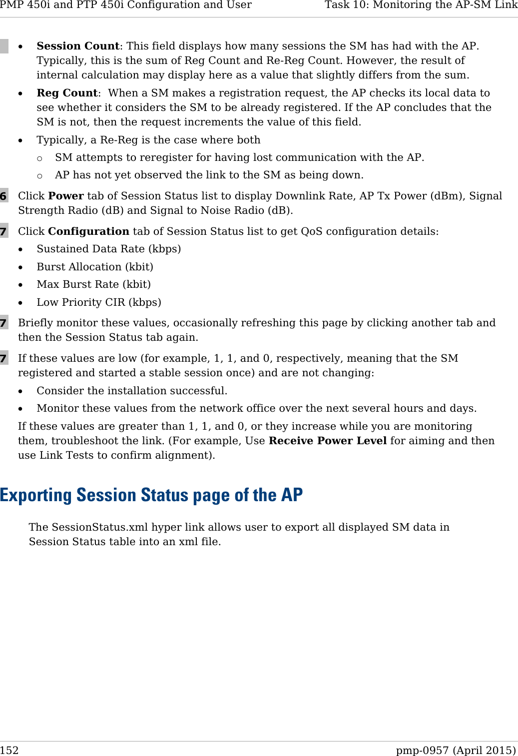
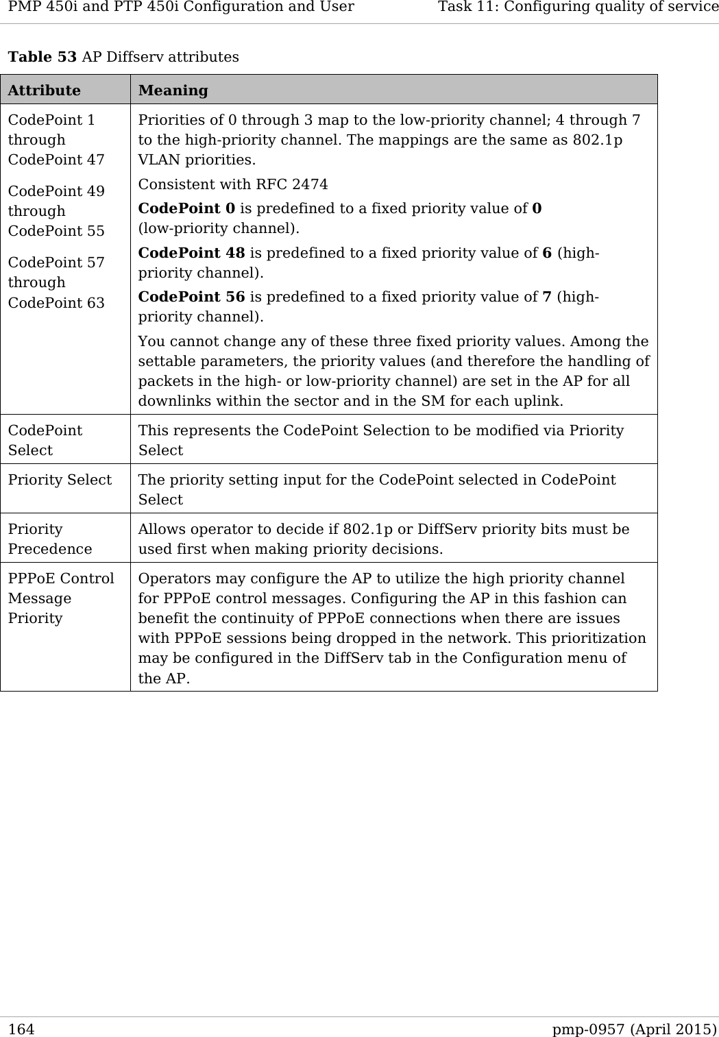
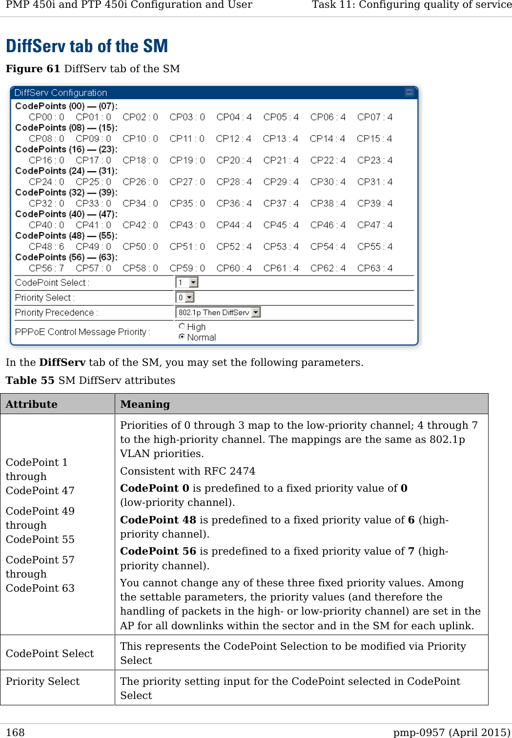

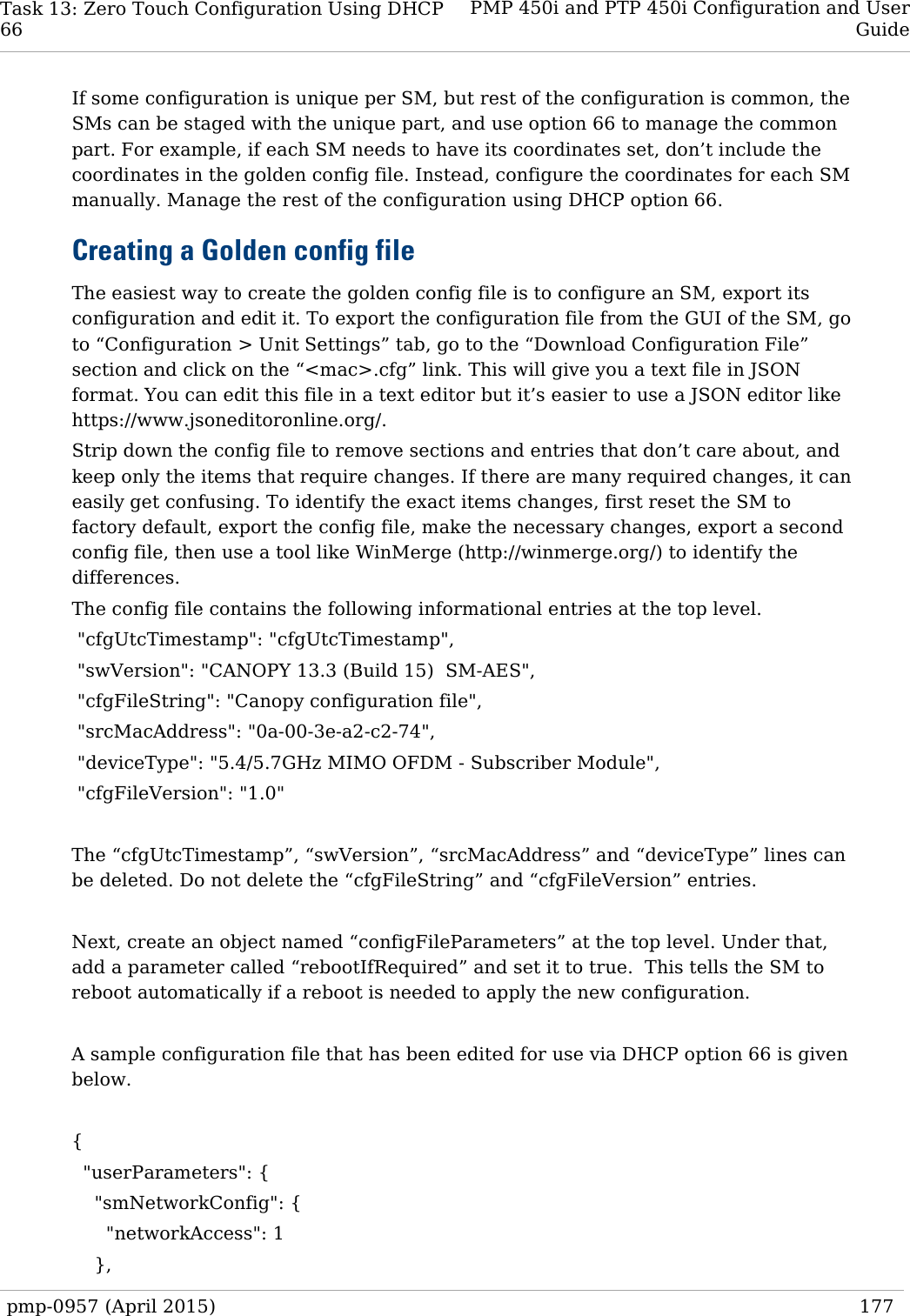
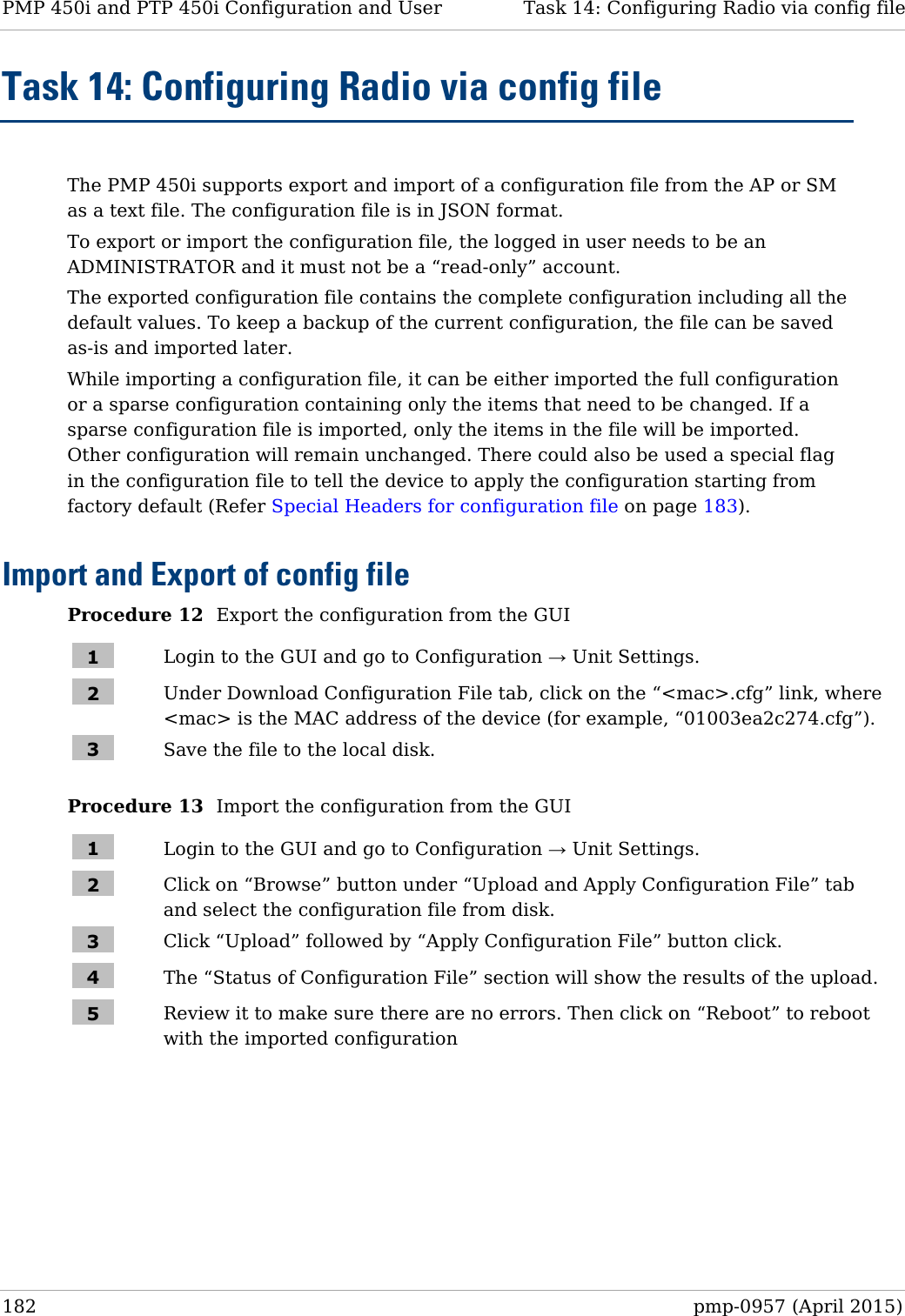
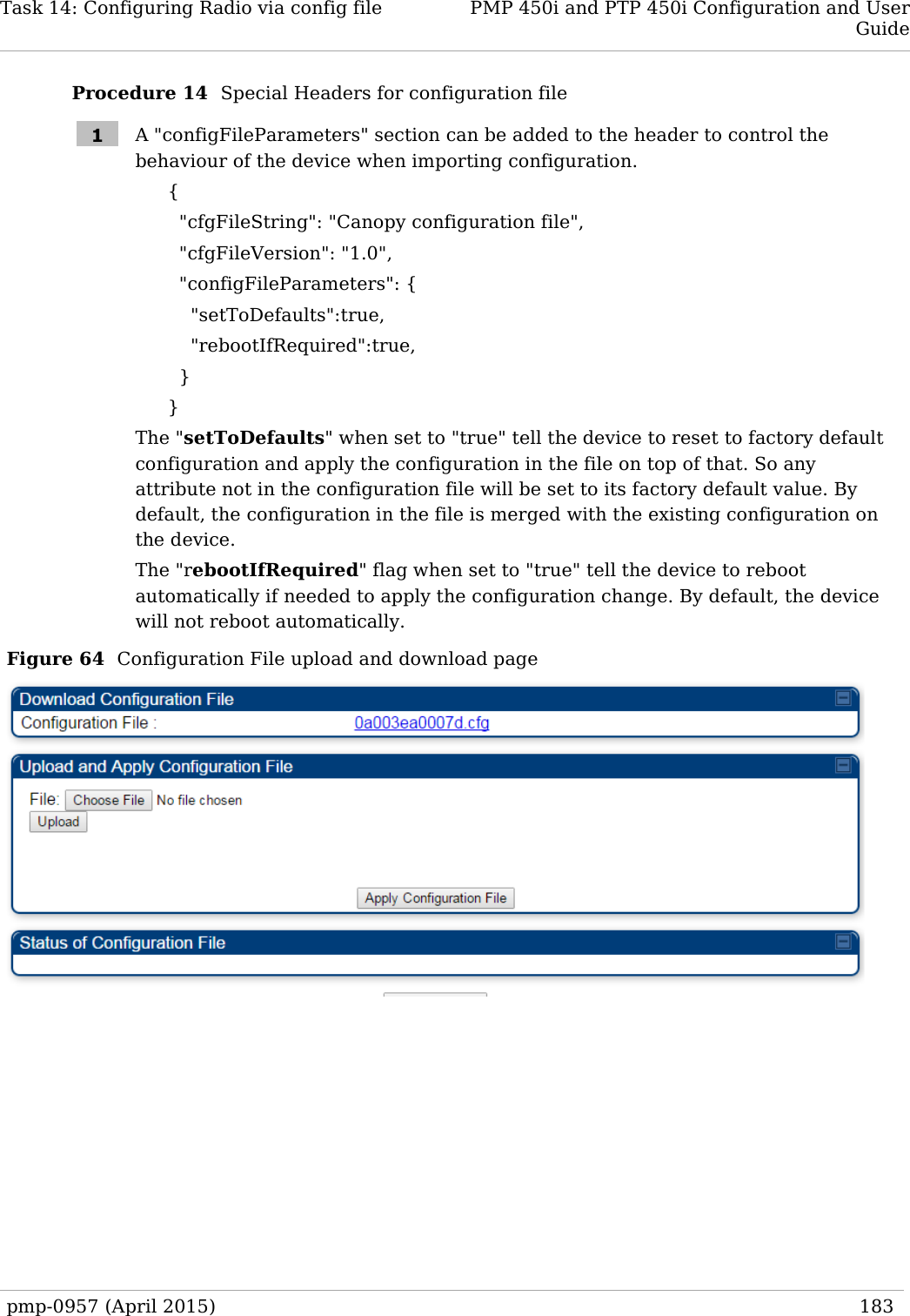
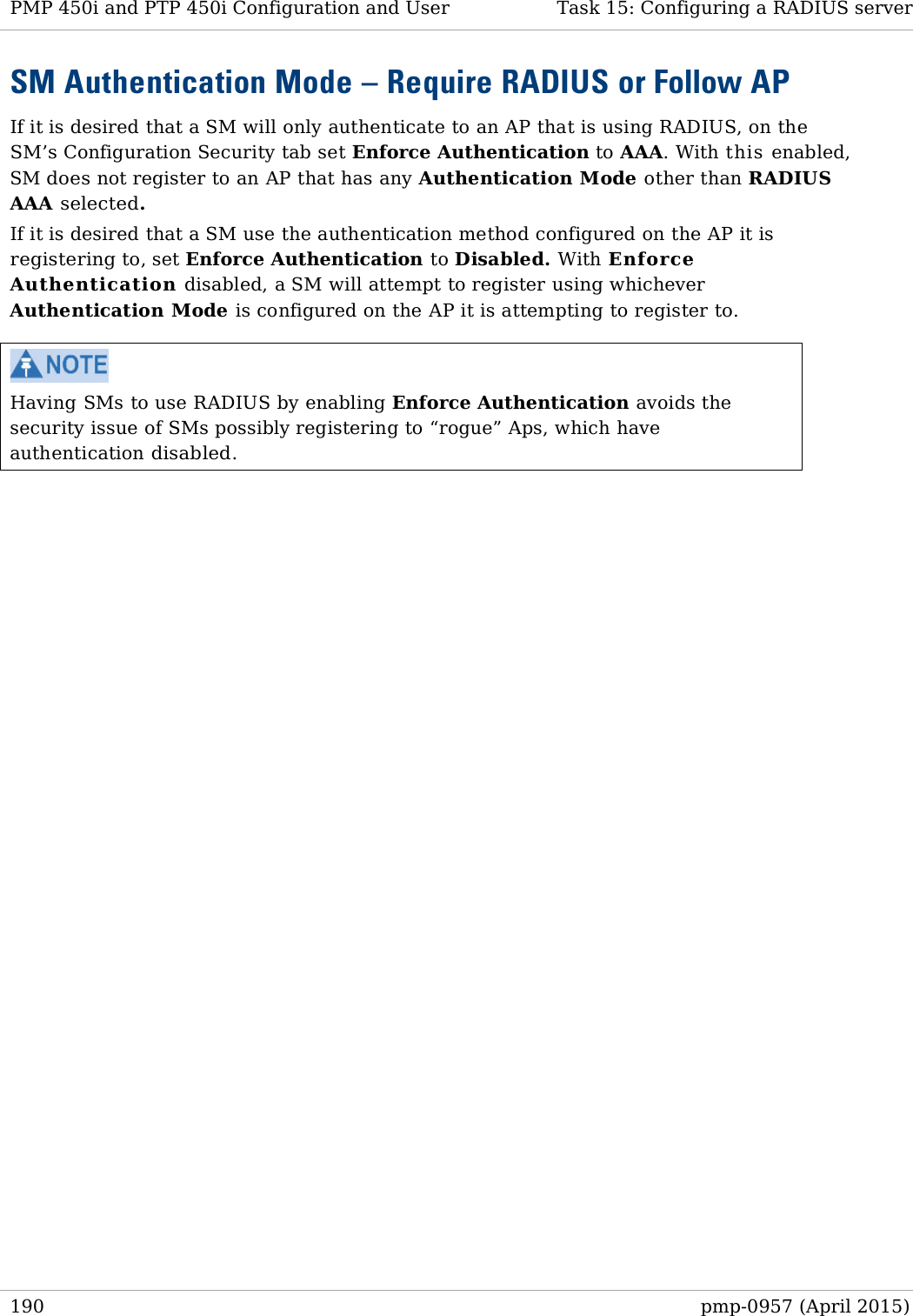
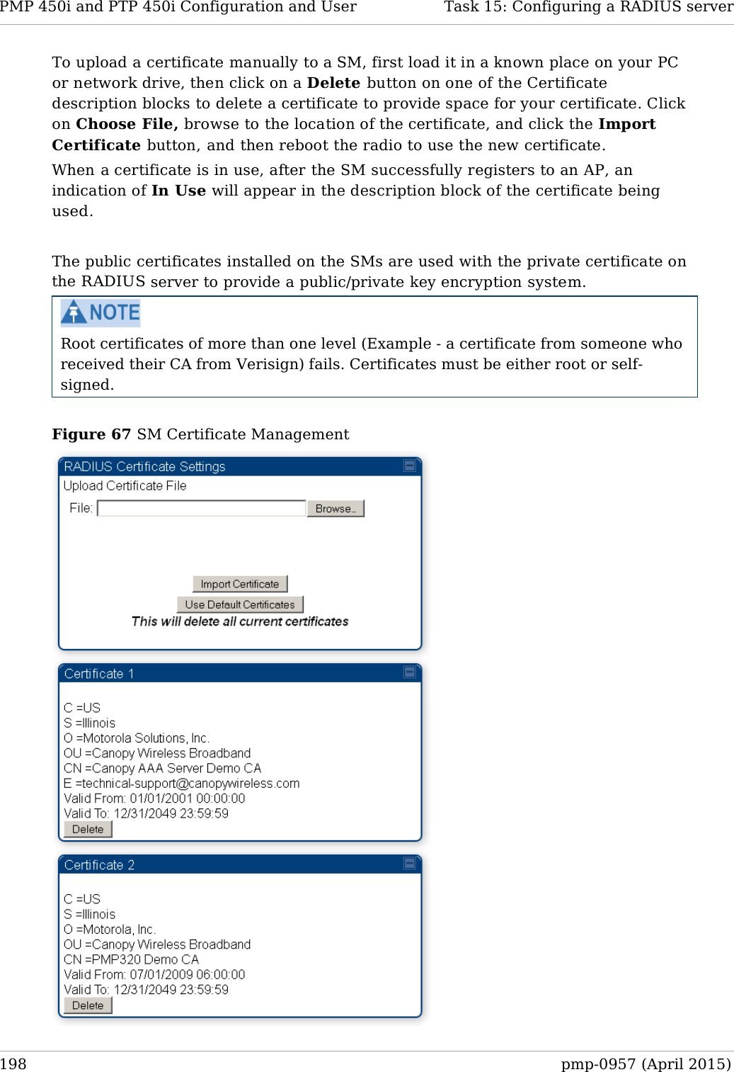
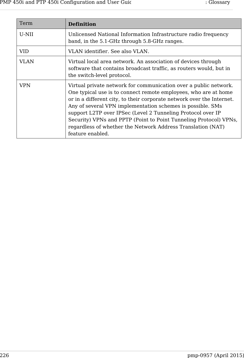
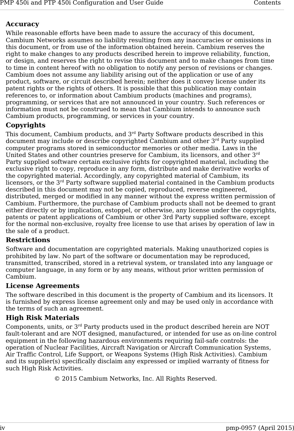
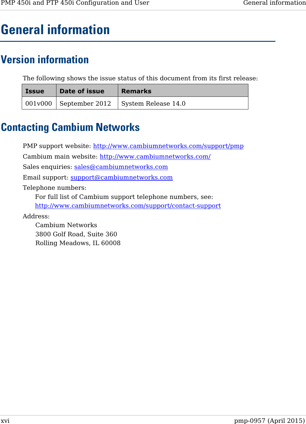
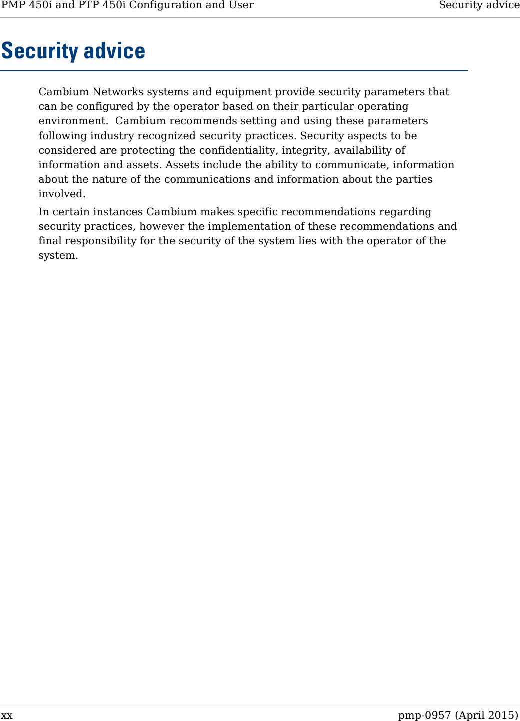
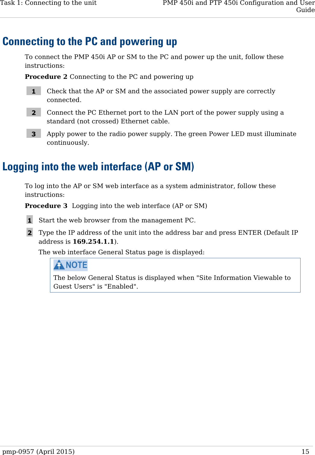
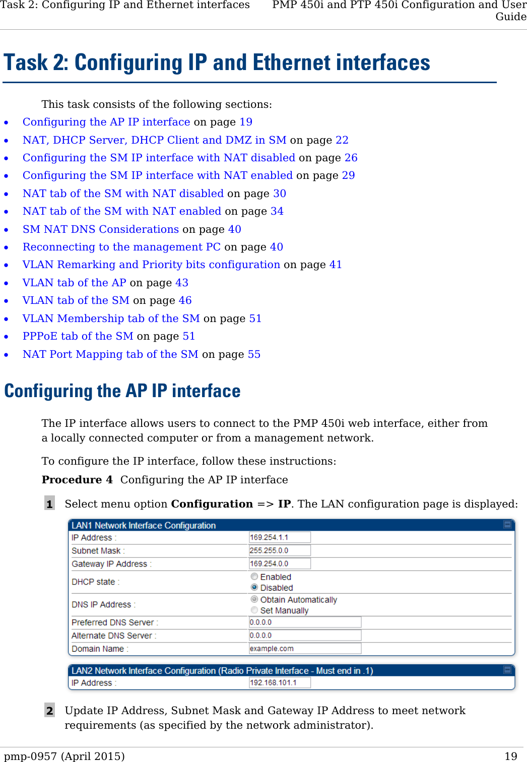
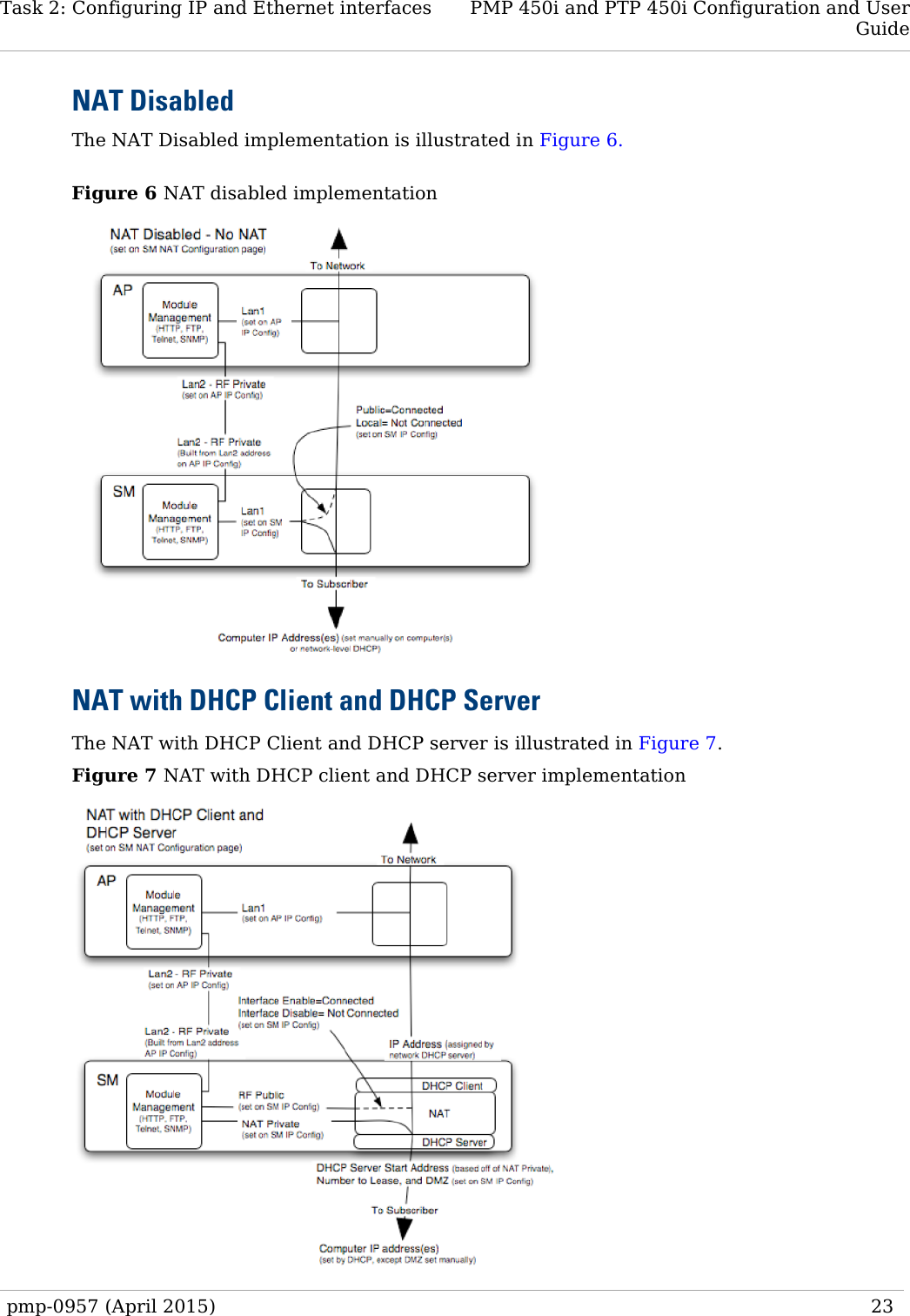
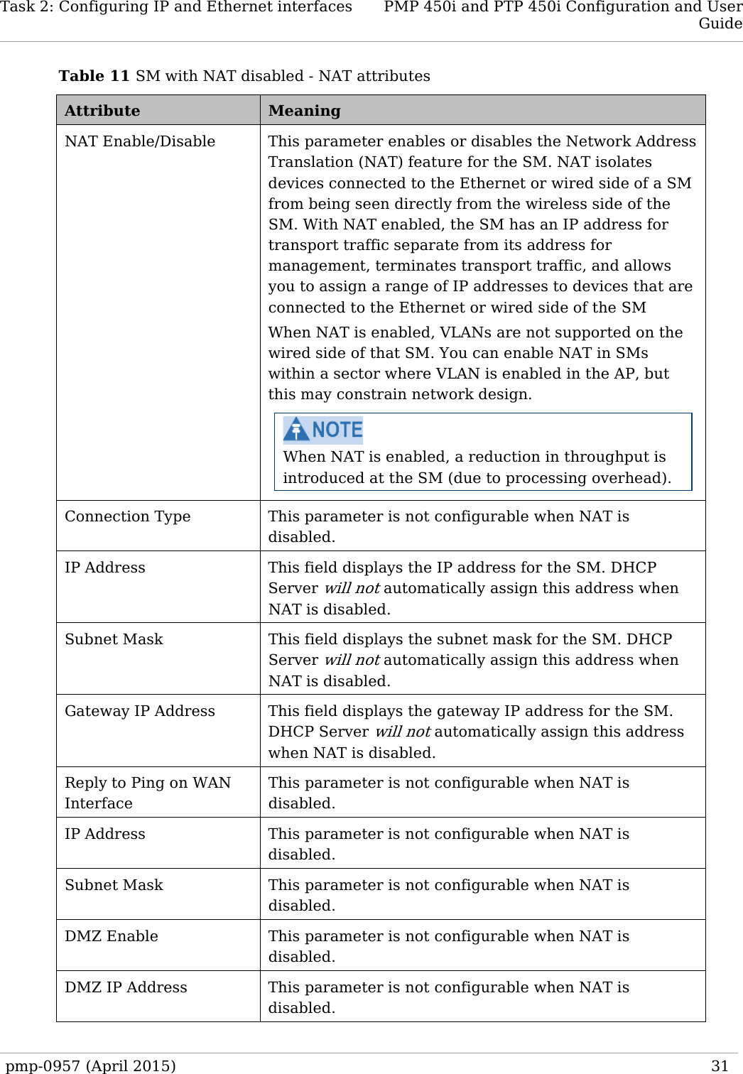
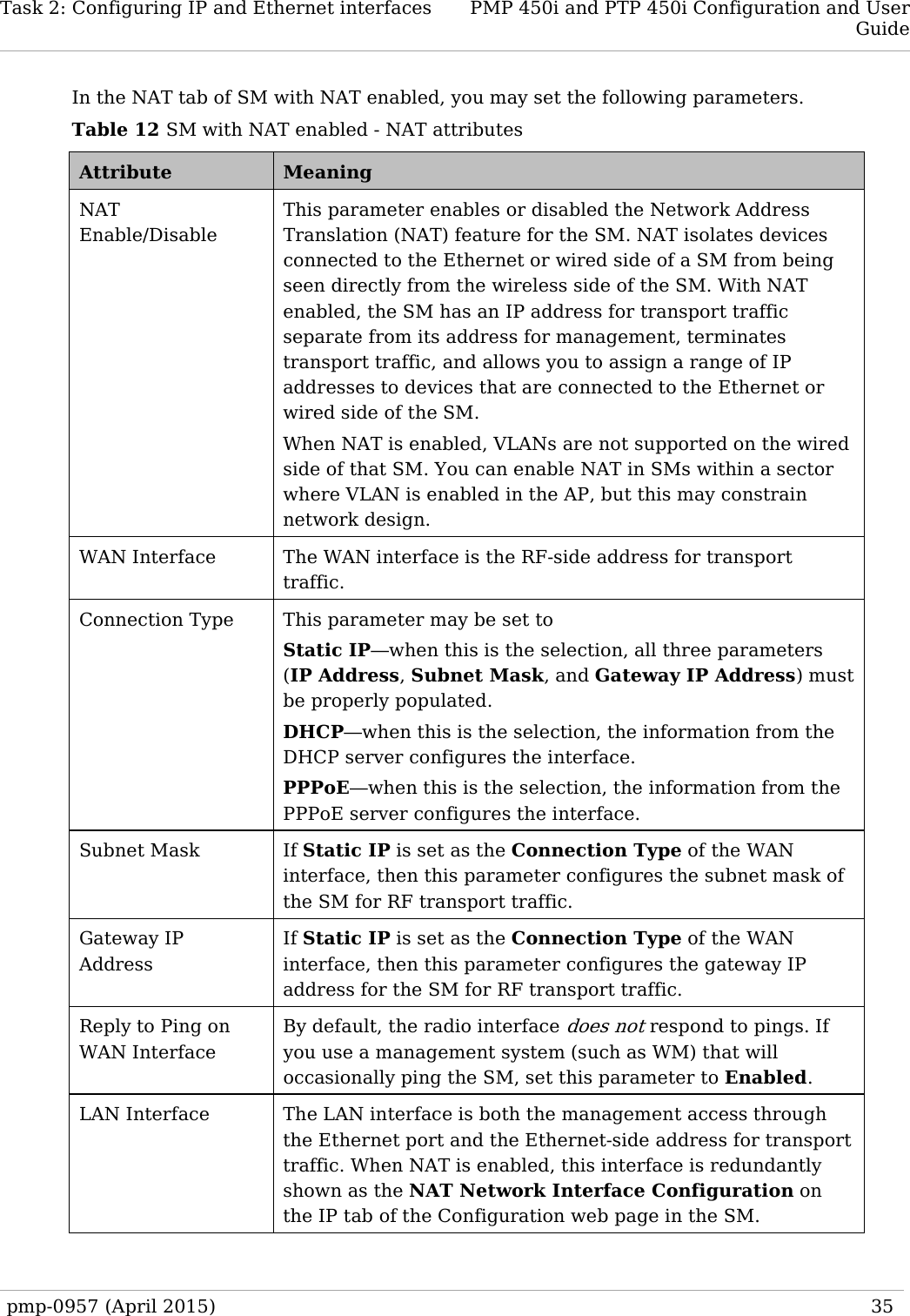
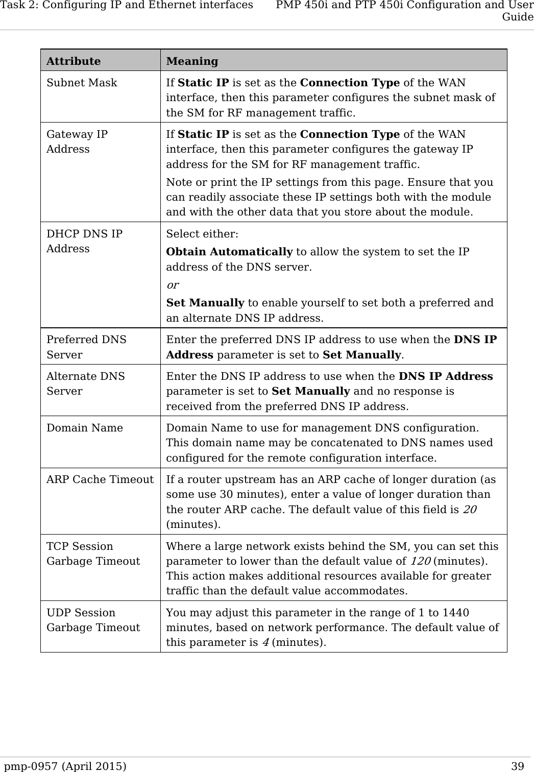
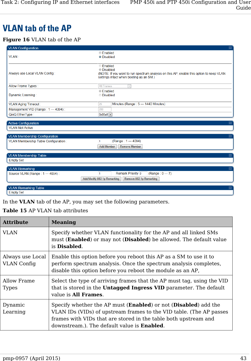
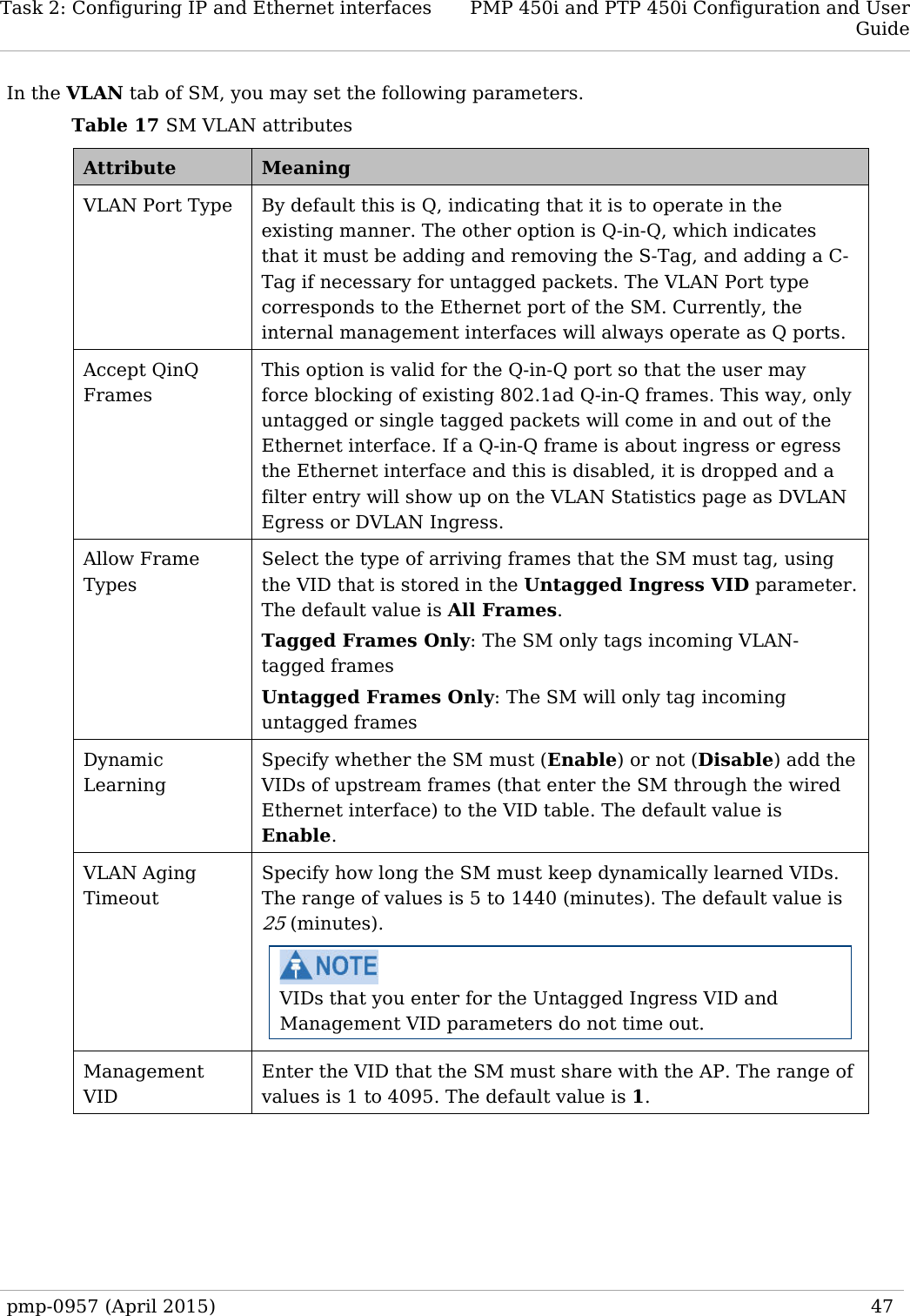
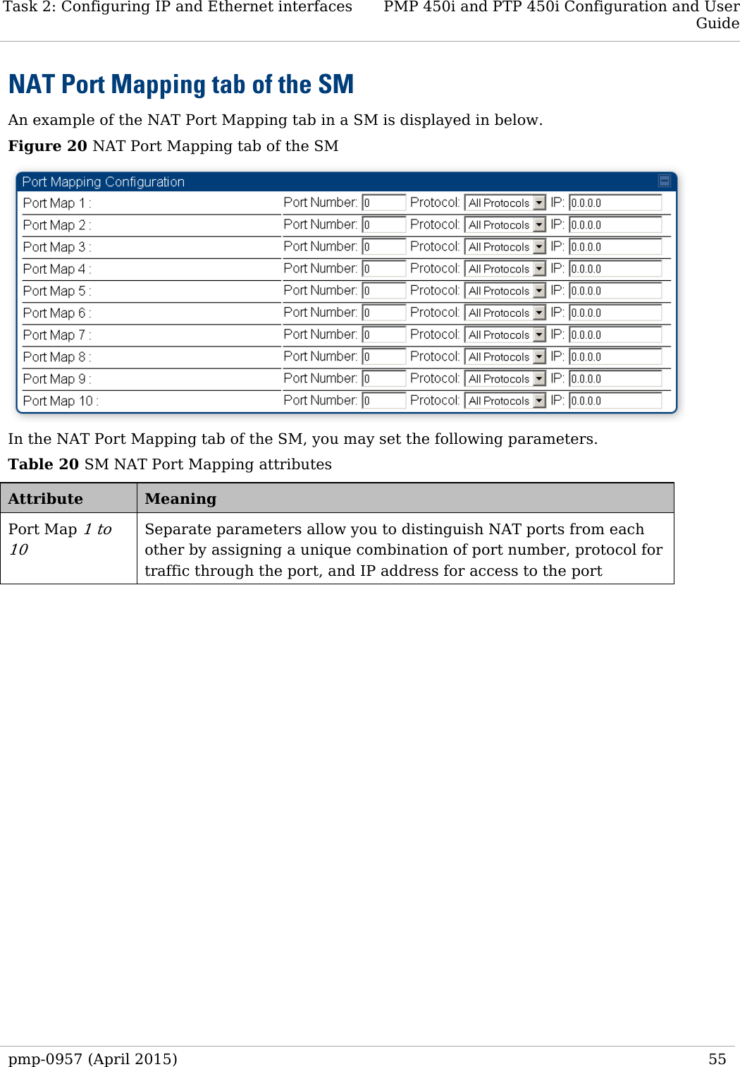
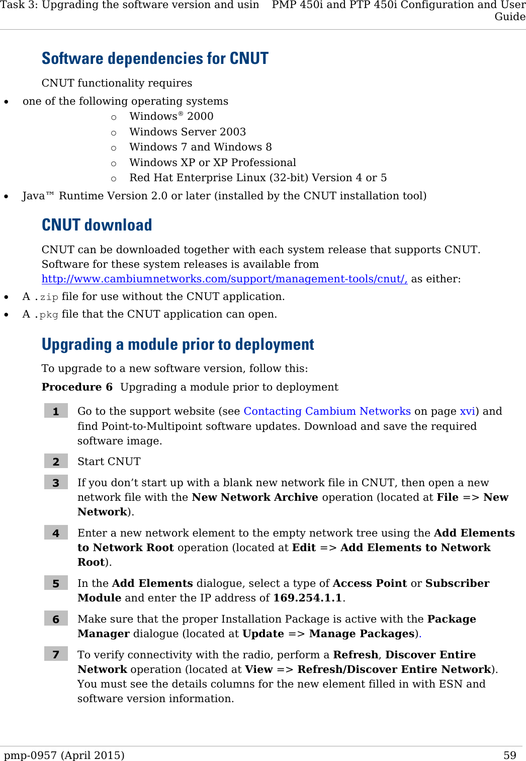
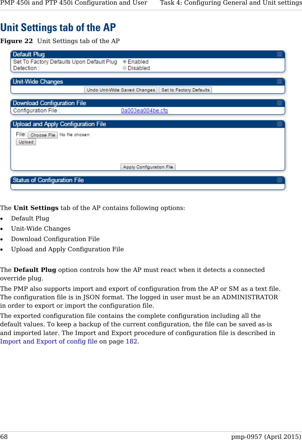
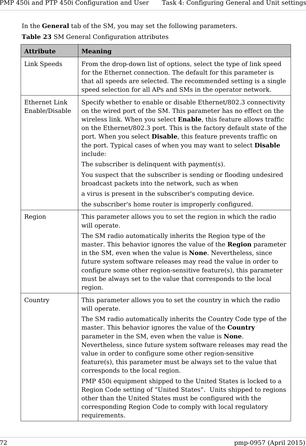
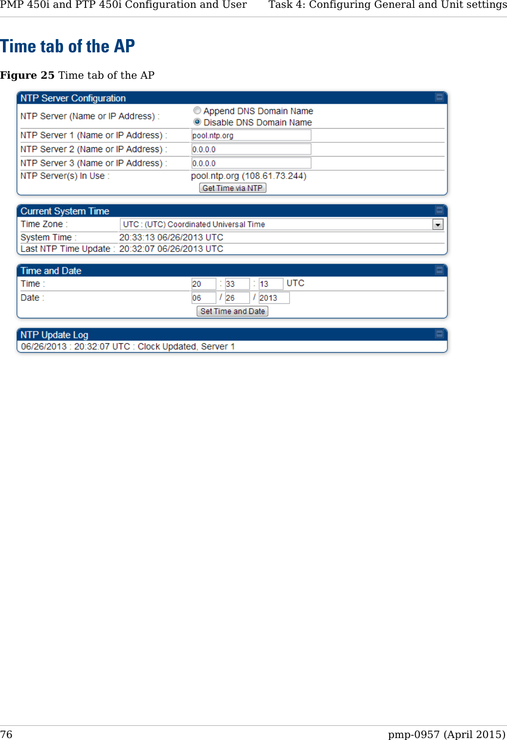
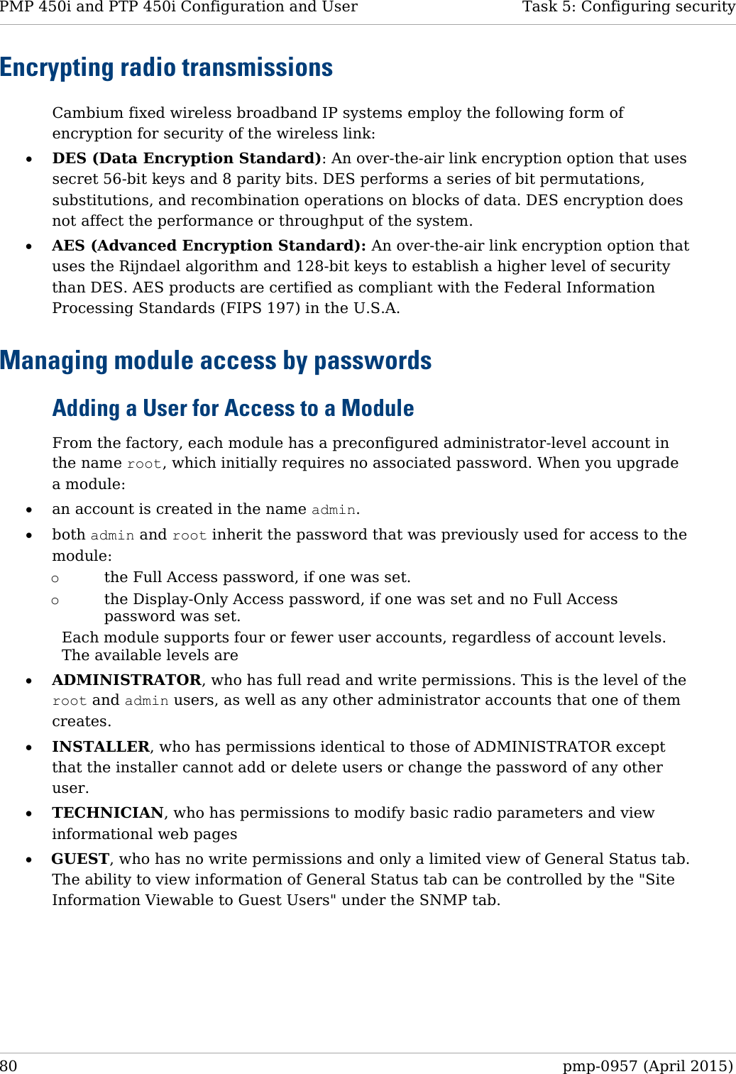
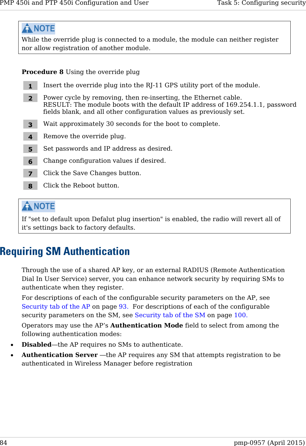
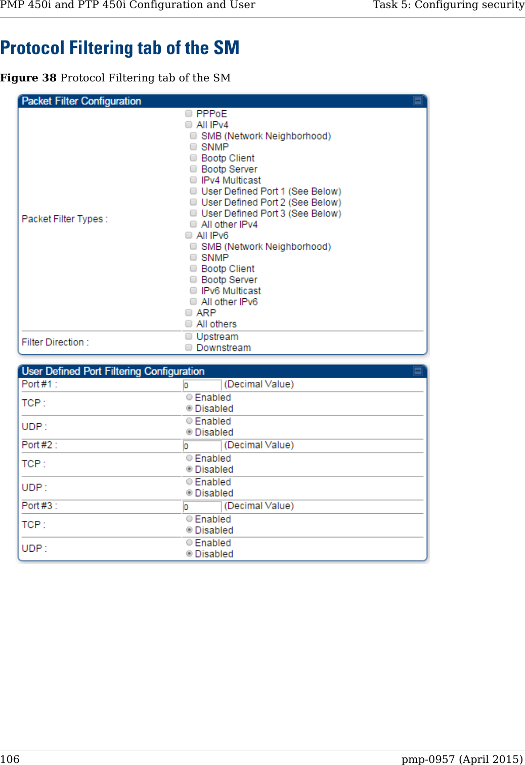
![PMP 450i and PTP 450i Configuration and User Task 13: Zero Touch Configuration Using DHCP Option 66 "location": { "siteName": "Test site" }, "smRadioConfig": { "frequencyScanList": [ 5475000, 5480000 ], "colorCodeList": [ { "colorCode": 42, "priority": 1 } ] }, "networkConfig": { "lanDhcpState": 1 } }, "cfgFileVersion": "1.0", "cfgFileString": "Canopy configuration file", "configFileParameters": { "rebootIfRequired": true } } When configuration is imported, only the items that exist in the configuration file are modified. Parameters that are not in the imported file are not changed. If user wish to revert those settings to their factory default values, please add a “setToDefaults” item under “configFileParameters” section with a value of true. "cfgFileVersion": "1.0", "cfgFileString": "Canopy configuration file", "configFileParameters": { "rebootIfRequired": true, "setToDefaults": true } In case, the SM needs to fetch the configuration file on each boot up even when not connecting to AP via ICC, set “Network Accessibility” to “Public” and “DHCP State” to “Enabled” in the “Configuration > IP” page before exporting the configuration. 178 pmp-0957 (April 2015)](https://usermanual.wiki/Cambium-Networks/50450I.Installation-Guide/User-Guide-2619716-Page-200.png)