Cambium Networks 50450I Wireless Ethernet Bridge, Dual Channel OFDM MIMO Combination Access Point, Subscriber Station and Point to Point Equipment User Manual PMP 450i and PTP 450i Configuration and User Guide
Cambium Networks Limited Wireless Ethernet Bridge, Dual Channel OFDM MIMO Combination Access Point, Subscriber Station and Point to Point Equipment PMP 450i and PTP 450i Configuration and User Guide
Contents
- 1. Installation Guide
- 2. User Guide Part 1
- 3. User Guide Part 2
- 4. User Guide Part 3
- 5. User Guide Part 4
- 6. User Guide Part 5
- 7. User Guide Part 6
- 8. User Guide Part 7
- 9. Exhibit D Users Manual per 2 1033 b3
- 10. User Manual - Part 1
- 11. User Manual - Part 2
- 12. User Manual - Part 3
- 13. User Manual - Part 4
- 14. Users Manual - Part 5
- 15. Users Manual - Part 6
- 16. User Manual
Installation Guide

PMP 450i and PTP 450i
Configuration and User
Guide
Release 14.0

PMP 450i and PTP 450i Configuration and User Guide Contents
ii pmp-0957 (April 2015)

PMP 450i and PTP 450i Configuration and User G
Contents
PMP 450i and PTP 450i module essential information
Default IP Address for Management
GUI Access 169.254.1.1
Default Administrator Username admin
Default Administrator Password (no password)
Software Upgrade Procedure
See “Updating the software version and
using CNUT” in the
PMP 450i
Configuration and User Guide
Resetting to Factory Defaults (2
options)
1. On the radio GUI, navigate to
Configuration, Unit Settings and select
Set to Factory Defaults
OR
2. On the radio GUI, navigate to
Configuration, Unit Settings and enable
and save option Set to Factory Defaults
Upon Default Plug Detection. When
the unit is powered on with a
default/override plug (see section
“Acquiring the Override Plug” in the
PMP 450i Configuration and User
Guide) the radio is returned to its
factory default settings.
pmp-0957 (April 2015) iii

PMP 450i and PTP 450i Configuration and User Guide Contents
Accuracy
While reasonable efforts have been made to assure the accuracy of this document,
Cambium Networks assumes no liability resulting from any inaccuracies or omissions in
this document, or from use of the information obtained herein. Cambium reserves the
right to make changes to any products described herein to improve reliability, function,
or design, and reserves the right to revise this document and to make changes from time
to time in content hereof with no obligation to notify any person of revisions or changes.
Cambium does not assume any liability arising out of the application or use of any
product, software, or circuit described herein; neither does it convey license under its
patent rights or the rights of others. It is possible that this publication may contain
references to, or information about Cambium products (machines and programs),
programming, or services that are not announced in your country. Such references or
information must not be construed to mean that Cambium intends to announce such
Cambium products, programming, or services in your country.
Copyrights
This document, Cambium products, and 3rd Party Software products described in this
document may include or describe copyrighted Cambium and other 3rd Party supplied
computer programs stored in semiconductor memories or other media. Laws in the
United States and other countries preserve for Cambium, its licensors, and other 3rd
Party supplied software certain exclusive rights for copyrighted material, including the
exclusive right to copy, reproduce in any form, distribute and make derivative works of
the copyrighted material. Accordingly, any copyrighted material of Cambium, its
licensors, or the 3rd Party software supplied material contained in the Cambium products
described in this document may not be copied, reproduced, reverse engineered,
distributed, merged or modified in any manner without the express written permission of
Cambium. Furthermore, the purchase of Cambium products shall not be deemed to grant
either directly or by implication, estoppel, or otherwise, any license under the copyrights,
patents or patent applications of Cambium or other 3rd Party supplied software, except
for the normal non-exclusive, royalty free license to use that arises by operation of law in
the sale of a product.
Restrictions
Software and documentation are copyrighted materials. Making unauthorized copies is
prohibited by law. No part of the software or documentation may be reproduced,
transmitted, transcribed, stored in a retrieval system, or translated into any language or
computer language, in any form or by any means, without prior written permission of
Cambium.
License Agreements
The software described in this document is the property of Cambium and its licensors. It
is furnished by express license agreement only and may be used only in accordance with
the terms of such an agreement.
High Risk Materials
Components, units, or 3rd Party products used in the product described herein are NOT
fault-tolerant and are NOT designed, manufactured, or intended for use as on-line control
equipment in the following hazardous environments requiring fail-safe controls: the
operation of Nuclear Facilities, Aircraft Navigation or Aircraft Communication Systems,
Air Traffic Control, Life Support, or Weapons Systems (High Risk Activities). Cambium
and its supplier(s) specifically disclaim any expressed or implied warranty of fitness for
such High Risk Activities.
© 2015 Cambium Networks, Inc. All Rights Reserved.
iv pmp-0957 (April 2015)

PMP 450i and PTP 450i Configuration and User G
Contents
Safety and regulatory information
This section describes important safety and regulatory guidelines that must be
observed by personnel installing or operating PMP 450i equipment.
Important safety information
To prevent loss of life or physical injury, observe the safety guidelines in
this section.
Power lines
Exercise extreme care when working near power lines.
Working at heights
Exercise extreme care when working at heights.
Grounding and protective earth
PMP 450i units must be properly grounded to protect against lightning. It is the
user’s responsibility to install the equipment in accordance with national
regulations. In the USA, follow Section 810 of the
National Electric Code,
ANSI/NFPA No.70-1984
(USA). In Canada, follow Section 54 of the
Canadian
Electrical Code
. These codes describe correct installation procedures for grounding
the outdoor unit, mast, lead-in wire and discharge unit, size of grounding
conductors and connection requirements for grounding electrodes. Other
regulations may apply in different countries and therefore it is recommended that
installation of the outdoor unit be contracted to a professional installer.
Powering down before servicing
Always power down and unplug the equipment before servicing.
Primary disconnect device
The AP or SM unit’s power supply is the primary disconnect device.
External cables
Safety may be compromised if outdoor rated cables are not used for connections
that is exposed to the outdoor environment.
pmp-0957 (April 2015) v

PMP 450i and PTP 450i Configuration and User Guide Contents
RF exposure near the antenna
Radio frequency (RF) fields is present close to the antenna when the transmitter is
on. Always turn off the power to the unit before undertaking maintenance activities
in front of the antenna.
Minimum separation distances
Install the AP or SM so as to provide and maintain the minimum separation
distances from people.
The minimum separation distances for each frequency variants are specified in the
PMP 450i Planning Guide.
Important regulatory information
The PMP 450i product is certified as an unlicensed device in frequency bands where
it is not allowed to cause interference to licensed services (called primary users of
the bands).
Radar avoidance
In countries where radar systems are the primary band users, the regulators have
mandated special requirements to protect these systems from interference caused
by unlicensed devices. Unlicensed devices must detect and avoid co-channel
operation with radar systems.
Installers and users must meet all local regulatory requirements for radar detection.
To meet these requirements, users must set the correct region code during
commissioning of the PMP 450i. If this is not done, installers and users may be
liable to civil and criminal penalties.
Contact the Cambium helpdesk if more guidance is required.
USA and Canada specific information
The USA Federal Communications Commission (FCC) has asked manufacturers to
implement special features to prevent interference to radar systems that operate in
the 5250-5350 and 5470-5725 MHz bands. These features must be implemented in
all products able to operate outdoors in the UNII band. The use of the 5600 – 5650
MHz band is prohibited, even with detect-and-avoid functionality implemented.
Manufacturers must ensure that such radio products cannot be configured to
operate outside of FCC rules; specifically it must not be possible to disable or
modify the radar protection functions that have been demonstrated to the FCC.
In order to comply with these FCC requirements, Cambium supplies variants of the
PMP 450i for operation in the USA or Canada. These variants are only allowed to
operate with region codes that comply with FCC/IC rule.
The list of FCC and Canada approved antennas for operation with the
PMP 450i/PTP 450i is provided in Appendix B.
vi pmp-0957 (April 2015)

PMP 450i and PTP 450i Configuration and User G
Contents
Renseignements spécifiques aux USA et au Canada
La Commission Fédérale des Communications des Etats-Unis (FCC) a demandé aux
fabricants de mettre en œuvre des mécanismes spécifiques pour éviter d’interférer
avec des systèmes radar fonctionnant dans la bande 5600 MHz à 5650 MHz. Ces
mécanismes doivent être mis en œuvre dans tous les produits capables de
fonctionner à l'extérieur dans la bande 5470 MHz à 5725 MHz.
Les fabricants doivent s'assurer que les produits de radiocommunications ne
peuvent pas être configurés pour fonctionner en dehors des règles de la FCC, en
particulier, il ne doit pas être possible de désactiver ou modifier les fonctions de
protection des radars qui ont été démontrés de la FCC.
Afin de se conformer à ces exigences de la FCC, Cambium fournit des variantes du
PMP 450i exclusivement pour les Etats-Unis ou au Canada. Ces variantes sont
autorisés à fonctionner avec des clés de licence qui sont conformes aux règles de la
FCC / IC. En particulier, le fonctionnement des canaux de radio qui chevauchent la
bande 5600-5650 MHz est interdite et ces canaux sont définitivement exclus.
La liste des antennes certifiées pour l’opération du PMP 450i/PTP 450i aux Etats
Unis conforme aux spécifications de La Commission Fédérale des Communications
des Etats-Unis (FCC) et au Canada est disponible dans l’Annexe B (Appendix B).
Specific expertise and training for professional installers
To ensure that the PMP 450i is installed and configured in compliance with the
requirements of Industry Canada and the FCC, installers must have the radio
engineering skills and training described in this section. This is particularly
important when installing and configuring a PMP 450i system for operation in the
5.1 GHz and 5.4 GHz UNII bands.
pmp-0957 (April 2015) vii

PMP 450i and PTP 450i Configuration and User Guide Contents
Contents
PMP 450i and PTP 450i module essential information ...................................................... iii
Safety and regulatory information .......................................................................... v
Important safety information ........................................................................................ v
Important regulatory information ................................................................................ vi
Specific expertise and training for professional installers ......................................... vii
About This Configuration and User Guide ..............................................................xv
General information .......................................................................................................... xvi
Version information .................................................................................................... xvi
Contacting Cambium Networks ................................................................................. xvi
Problems and warranty .................................................................................................. xviii
Security advice .................................................................................................................. xx
Warnings, cautions and notes .......................................................................................... xxi
Chapter 1: Reference information ........................................................................ 1
Wireless specifications ........................................................................................................ 2
General wireless specifications ..................................................................................... 2
Compliance with safety standards ...................................................................................... 3
Electrical safety compliance.......................................................................................... 3
Electromagnetic compatibility (EMC) compliance ....................................................... 3
Human exposure to radio frequency energy ................................................................ 4
Compliance with radio regulations ..................................................................................... 7
Type approvals ............................................................................................................... 7
DFS for 5 GHz Radios .................................................................................................... 8
FCC IDs and certification numbers ............................................................................. 10
Chapter 2: Configuration ................................................................................... 11
Preparing for configuration ............................................................................................... 12
Safety precautions during configuration .................................................................... 12
Task 1: Connecting to the unit .......................................................................................... 13
Configuring the management PC ................................................................................ 13
Connecting to the PC and powering up ...................................................................... 15
Logging into the web interface (AP or SM) ................................................................ 15
Task 2: Configuring IP and Ethernet interfaces ............................................................... 19
Configuring the AP IP interface .................................................................................. 19
NAT, DHCP Server, DHCP Client and DMZ in SM ..................................................... 22
Configuring the SM IP interface with NAT disabled .................................................. 26
Configuring the SM IP interface with NAT enabled ................................................... 29
NAT tab of the SM with NAT disabled ........................................................................ 30
NAT tab of the SM with NAT enabled ......................................................................... 34
Reconnecting to the management PC ......................................................................... 40
VLAN Remarking and Priority bits configuration ........................................................ 41
VLAN tab of the AP ...................................................................................................... 43
viii pmp-0957 (April 2015)

PMP 450i and PTP 450i Configuration and User G
Contents
VLAN tab of the SM ..................................................................................................... 46
VLAN Membership tab of the SM ............................................................................... 51
PPPoE tab of the SM.................................................................................................... 51
NAT Port Mapping tab of the SM ................................................................................ 55
Task 3: Upgrading the software version and using CNUT ............................................... 56
Checking the installed software version ..................................................................... 56
Upgrading to a new software version ......................................................................... 56
Task 4: Configuring General and Unit settings ................................................................ 61
General tab of the AP’s Configuration section............................................................ 61
Unit Settings tab of the AP .......................................................................................... 68
General tab of the SM ................................................................................................. 71
Unit Settings tab of the SM ......................................................................................... 74
Time tab of the AP ....................................................................................................... 76
Task 5: Configuring security ............................................................................................. 79
Isolating APs from the internet ................................................................................... 79
Encrypting radio transmissions .................................................................................. 80
Managing module access by passwords ..................................................................... 80
Requiring SM Authentication ...................................................................................... 84
Filtering protocols and ports ....................................................................................... 85
Encrypting downlink broadcasts ................................................................................. 87
Isolating SMs ............................................................................................................... 88
Filtering management through Ethernet .................................................................... 88
Allowing management only from specified IP addresses ........................................... 88
Configuring management IP by DHCP........................................................................ 89
Restricting radio Telnet access over the RF interface ............................................... 89
Security tab of the AP .................................................................................................. 93
Filtering protocols and ports ....................................................................................... 97
Protocol Filtering tab of the AP................................................................................... 97
Port configuration tab of the AP ................................................................................. 99
Security tab of the SM ............................................................................................... 100
Protocol Filtering tab of the SM................................................................................ 106
Port Configuration tab of the SM .............................................................................. 108
Task 6: Configuring radio parameters ............................................................................ 109
Radio tab of the AP .................................................................................................... 109
Radio tab of the SM ................................................................................................... 123
Task 7: Setting up SNMP agent ...................................................................................... 134
SNMP tab of the AP ................................................................................................... 135
SNMP tab of the SM .................................................................................................. 139
Task 8: Configuring syslog .............................................................................................. 144
Configuring AP system logging (syslog) ................................................................... 145
Configuring SM system logging (syslog) .................................................................. 146
Task 9: Configuring remote access ................................................................................. 148
Configuring SM IP over-the-air access ..................................................................... 148
Accessing SM over-the-air by LUID .......................................................................... 149
Task 10: Monitoring the AP-SM Link .............................................................................. 151
Monitoring the AP-SM Link ....................................................................................... 151
pmp-0957 (April 2015) ix

PMP 450i and PTP 450i Configuration and User Guide Contents
Exporting Session Status page of the AP .................................................................. 152
Task 11: Configuring quality of service .......................................................................... 154
Maximum Information Rate (MIR) Parameters ........................................................ 154
Token Bucket Algorithm ............................................................................................ 154
MIR Data Entry Checking ......................................................................................... 155
Committed Information Rate (CIR) ........................................................................... 155
Bandwidth from the SM Perspective ........................................................................ 156
Interaction of Burst Allocation and Sustained Data Rate Settings .......................... 156
High-priority Bandwidth ............................................................................................ 156
Traffic Scheduling ..................................................................................................... 158
Setting the Configuration Source ............................................................................. 159
Quality of Service (QoS) tab of the AP ...................................................................... 161
DiffServ tab of the AP ................................................................................................ 163
Quality of Service (QoS) tab of the SM ..................................................................... 165
DiffServ tab of the SM ............................................................................................... 168
Task 12: Performing an Sector Wide SA ......................................................................... 170
Using Spectrum Analyzer tool ................................................................................... 171
Using the Remote Spectrum Analyzer tool ............................................................... 174
Task 13: Zero Touch Configuration Using DHCP Option 66 .......................................... 176
Configuration Steps ................................................................................................... 176
Troubleshooting ......................................................................................................... 181
Task 14: Configuring Radio via config file ...................................................................... 182
Import and Export of config file ................................................................................ 182
Task 15: Configuring a RADIUS server .......................................................................... 184
Understanding RADIUS for PMP 450i ...................................................................... 184
Choosing Authentication Mode and Configuring for Authenti
c
ation Ser
v
er
s - AP
................................................................................................................................... 185
SM Authentication Mode – Require RADIUS or Follow AP .................................. 190
Handling Certificates ................................................................................................ 197
Configuring your RADIUS servers for SM authentication ....................................... 199
Assigning SM management IP addressing via RADIUS ........................................... 200
Configuring your RADIUS server for SM configuration ........................................... 200
Using RADIUS for centralized AP and SM user name and password management 204
RADIUS Device Data Accounting .............................................................................. 208
RADIUS Device Re-authentication ............................................................................ 212
Appendix A : Glossary ...................................................................................... 213
Appendix B : FCC and IC approved antennas .................................................... 227
x pmp-0957 (April 2015)

List of Figures
Figure 1 AP DFS Status ............................................................................................................ 8
Figure 2 AP General Status page, GUEST user example ....................................................... 16
Figure 3 SM General Status page, GUEST user example ...................................................... 16
Figure 4 AP General Status page, ADMINISTRATOR user example ..................................... 17
Figure 5 SM General Status page, ADMINISTRATOR user example .................................... 18
Figure 6 NAT disabled implementation .................................................................................. 23
Figure 7 NAT with DHCP client and DHCP server implementation ...................................... 23
Figure 8 NAT with DHCP client implementation ................................................................... 24
Figure 9 NAT with DHCP server implementation .................................................................. 24
Figure 10 NAT without DHCP implementation ...................................................................... 25
Figure 11 IP tab of the SM with NAT disabled ...................................................................... 26
Figure 12 IP tab of SM ............................................................................................................ 26
Figure 13 IP tab of SM with NAT enabled ............................................................................. 29
Figure 14 SM with NAT disabled ........................................................................................... 30
Figure 15 NAT tab of the SM with NAT enabled ................................................................... 34
Figure 16 VLAN tab of the AP ................................................................................................ 43
Figure 17 VLAN tab of the SM ............................................................................................... 46
Figure 18 VLAN Membership tab of the SM .......................................................................... 51
Figure 19 PPPoE tab of the SM .............................................................................................. 51
Figure 20 NAT Port Mapping tab of the SM .......................................................................... 55
Figure 21 General tab ............................................................................................................. 61
Figure 22 Unit Settings tab of the AP ................................................................................... 68
Figure 23 General tab of the SM ............................................................................................ 71
Figure 24 Unit Settings tab of the SM ................................................................................... 74
Figure 25 Time tab of the AP .................................................................................................. 76
Figure 26 AP / SM Add User tab of account page .................................................................. 81
Figure 27 Delete User tab of the AP / SM .............................................................................. 81
Figure 28 Change User Setting tab AP / SM .......................................................................... 82
Figure 29 AP Evaluation Configuration parameter of Security tab ....................................... 82
Figure 30 RJ-11 pin out for the override plug ........................................................................ 83
Figure 31 Categorical protocol filtering ................................................................................. 86
Figure 32 RF Telnet Access Restrictions (orange) and Flow through (green) ...................... 90
Figure 33 RF Telnet Access Restriction (orange) and Potential Security Hole (green) ....... 90
Figure 34 Security tab of the AP ............................................................................................ 93
Figure 35 Protocol Filtering tab of the AP ............................................................................. 97
Figure 36 Port Configuration tab of the AP .......................................................................... 99
Figure 37 Security tab of the SM ........................................................................................ 100
Figure 38 Protocol Filtering tab of the SM .......................................................................... 106
Figure 39 Port Configuration tab of the SM ........................................................................ 108
Figure 40 Radio tab of the AP for 5 GHz .............................................................................. 109

PMP 450i and PTP 450i Configuration and User Guide List of Figures
Figure 41 Multicast VC statistics ......................................................................................... 117
Figure 42 Multicast scheduler statistics .............................................................................. 117
Figure 43 DiffServ tab on AP and SM .................................................................................. 120
Figure 44 Protocol filtering tab on AP and SM (Packet Filter Configuration section) ....... 122
Figure 45 Radio tab of the SM for 5 GHz ............................................................................. 123
Figure 46 Speedtest results example with 1 AP and 1 SM .................................................. 132
Figure 47 SNMP tab of the AP ............................................................................................ 135
Figure 48 SNMP tab of the SM ............................................................................................ 139
Figure 49 AP Syslog Configuration page ............................................................................. 145
Figure 50 SM Syslog Configuration page ............................................................................ 146
Figure 51 SM IP Configuration page .................................................................................... 148
Figure 52 AP Session Status page ........................................................................................ 150
Figure 53 AP Remote Subscribers page ............................................................................... 150
Figure 54 AP Session Status page ....................................................................................... 151
Figure 55 Exporting Session Status page of the AP ........................................................... 153
Figure 56 Uplink and downlink rate caps adjusted to apply aggregate cap ....................... 155
Figure 57 Uplink and downlink rate cap adjustment example ............................................ 155
Figure 58 Quality of Service (QoS) tab of the AP ................................................................. 161
Figure 59 Diffserv tab of the AP ........................................................................................... 163
Figure 60 Quality of Service (QoS) tab of the SM ................................................................ 165
Figure 61 DiffServ tab of the SM ......................................................................................... 168
Figure 62 Spectrum Analyzer tab of the AP/ SM ................................................................ 171
Figure 63 Remote Spectrum Analyzer tab of the AP .......................................................... 174
Figure 64 Configuration File upload and download page ................................................... 183
Figure 65 Security tab of the AP .......................................................................................... 186
Figure 66 Security tab of the SM ......................................................................................... 191
Figure 67 SM Certificate Management ................................................................................ 198
Figure 68 User Authentication and Access Tracking tab of the AP .................................... 205
Figure 69 User Authentication and Access Tracking tab of the SM ................................... 207
Figure 70 RADIUS accounting messages configuration ..................................................... 211
Figure 71 Device re-authentication configuration ............................................................... 212
xii pmp-0957 (April 2015)

PMP 450i and PTP 450i Configuration and User G
List of Tables
List of Tables
Table 1 PMP 450i wireless specifications ........................................................................ 2
Table 2 PMP 450i safety compliance specifications ........................................................ 3
Table 3 EMC emissions compliance ................................................................................. 3
Table 4 Minimum Safe Separation Distance .................................................................... 6
Table 5 Radio certifications .............................................................................................. 7
Table 6 OFDM DFS operation based on Country Code setting ....................................... 9
Table 7 US FCC IDs Numbers and Covered Configurations ......................................... 10
Table 8 IP interface attributes ......................................................................................... 21
Table 9 SM with NAT disabled - IP attributes ................................................................. 27
Table 10 SM with NAT enabled - IP attributes ............................................................... 29
Table 11 SM with NAT disabled - NAT attributes ........................................................... 31
Table 12 SM with NAT enabled - NAT attributes ............................................................ 35
Table 13 SM DNS Options with NAT Enabled ................................................................ 40
Table 14 VLAN Remarking Example ............................................................................... 41
Table 15 AP VLAN tab attributes .................................................................................... 43
Table 16 Q-in-Q Ethernet frame ...................................................................................... 44
Table 17 SM VLAN attributes .......................................................................................... 47
Table 18 SM VLAN Membership attributes ................................................................... 51
Table 19 SM PPPoE attributes ........................................................................................ 52
Table 20 SM NAT Port Mapping attributes ..................................................................... 55
Table 21 AP General tab attributes ................................................................................. 62
Table 22 AP Unit Settings attributes ............................................................................... 69
Table 23 SM General Configuration attributes ............................................................... 72
Table 24 SM Unit Settings attributes .............................................................................. 75
Table 25 AP Time attributes ............................................................................................ 77
Table 26 Ports filtered per protocol selection ................................................................. 87
Table 27 AP Security attributes ....................................................................................... 94
Table 28 AP Protocol Filtering attributes ........................................................................ 98
Table 29 AP Port Configuration attributes ...................................................................... 99
Table 30 SM Security attributes ................................................................................... 101
Table 31 SM Protocol Filtering attributes ..................................................................... 107
Table 32 SM Port Configuration attributes .................................................................. 108
Table 33 AP Radio attributes ......................................................................................... 110
Table 34 Example for mix of multicast and unicast traffic scenarios ........................... 116
Table 35 DiffServ attributes .......................................................................................... 120
Table 36 DiffServ SNMP objects ................................................................................... 121
Table 37 Packet Filter Configuration attributes (IPv6 only) ......................................... 122
Table 38 SM Radio attributes ........................................................................................ 125
pmp-0957 (April 2015) xiii

List of Tables PMP 450i and PTP 450i Configuration and User
Guide
Table 39 PMP 450i Modulation levels ........................................................................... 130
Table 40 Co-channel Interference per (CCI) MCS, PMP/PTP 450i ............................... 130
Table 41 Adjacent Channel Interference (ACI) per MCS, PMP/PTP 450i .................... 131
Table 42 AP SNMP attributes ........................................................................................ 136
Table 43 SM SNMP attributes ....................................................................................... 141
Table 44 Syslog enhancements...................................................................................... 144
Table 45 AP Syslog Configuration attributes ................................................................ 145
Table 46 Syslog Configuration attributes ...................................................................... 146
Table 47 SM IP Configuration attributes ...................................................................... 148
Table 48 Characteristics of traffic scheduling .............................................................. 158
Table 49 Recommended combined settings for typical operations .............................. 159
Table 50 Where feature values are obtained for a SM with authentication required . 160
Table 51 Where feature values are obtained for a SM with authentication disabled .. 160
Table 52 AP QoS attributes ............................................................................................ 161
Table 53 AP Diffserv attributes ..................................................................................... 164
Table 54 SM Quality of Service attributes .................................................................... 165
Table 55 SM DiffServ attributes .................................................................................... 168
Table 56 Spectrum Analyzer attributes ........................................................................ 173
Table 57 Remote Spectrum Analyzer tab attributes ..................................................... 175
Table 58 Security tab attributes .................................................................................... 187
Table 59 SM Security tab attributes ............................................................................. 193
Table 60 RADIUS Vendor Specific Attributes (VSAs) ................................................... 201
Table 61 AP User Authentication and Access Tracking attributes ............................... 205
Table 62 SM User Authentication and Access Tracking attributes .............................. 207
Table 63 Device data accounting RADIUS attributes ................................................... 208
Table 64 Glossary ........................................................................................................... 213
Table 65 FCC and IC approved antennas list .............................................................. 227
xiv pmp-0957 (April 2015)

PMP 450i and PTP 450i Configuration and User Guide
About This Configuration and User Guide
This guide describes the configuration of the Cambium PMP 450i Series of
point-to-multipoint wireless equipment deployment. It is intended for use by the
system administrator.
After the initial general and legal information, the guide begins with a set of
tasks to complete a basic configuration of the equipment. Once this
configuration is complete, the units are ready for deployment. Advanced
configuration, also defined in this document, may be initiated at the operator’s
discretion.

PMP 450i and PTP 450i Configuration and User
General information
General information
Version information
The following shows the issue status of this document from its first release:
Issue Date of issue Remarks
001v000 September 2012 System Release 14.0
Contacting Cambium Networks
PMP support website: http://www.cambiumnetworks.com/support/pmp
Cambium main website: http://www.cambiumnetworks.com/
Sales enquiries: sales@cambiumnetworks.com
Email support: support@cambiumnetworks.com
Telephone numbers:
For full list of Cambium support telephone numbers, see:
http://www.cambiumnetworks.com/support/contact-support
Address:
Cambium Networks
3800 Golf Road, Suite 360
Rolling Meadows, IL 60008
xvi pmp-0957 (April 2015)

General information PMP 450i and PTP 450i Configuration and User
Guide
Purpose
Cambium Networks Point-To-Multipoint (PMP) documents are intended to
instruct and assist personnel in the operation, installation and maintenance of
the Cambium PMP equipment and ancillary devices. It is recommended that all
personnel engaged in such activities be properly trained.
Cambium disclaims all liability whatsoever, implied or express, for any risk of
damage, loss or reduction in system performance arising directly or indirectly
out of the failure of the customer, or anyone acting on the customer's behalf, to
abide by the instructions, system parameters, or recommendations made in this
document.
Cross references
References to external publications are shown in italics. Other cross references,
emphasized in blue text in electronic versions, are active links to the references.
This document is divided into numbered chapters that are divided into sections.
Sections are not numbered, but are individually named at the top of each page
and are listed in the table of contents.
Feedback
We appreciate feedback from the users of our documents. This includes
feedback on the structure, content, accuracy, or completeness of our
documents. Send feedback to email support (see ‘Contacting Cambium
Networks’).
pmp-0957 (April 2015) xvii

PMP 450i and PTP 450i Configuration and User
Problems and warranty
Problems and warranty
Reporting problems
If any problems are encountered when installing or operating this equipment,
follow this procedure to investigate and report:
1 Search this document and the software release notes of supported releases.
2 Visit the support website. http://www.cambiumnetworks.com/support
3 Ask for assistance from the Cambium product supplier.
4 Gather information from affected units such as:
• The IP addresses and MAC addresses.
• The software releases.
• The configuration of software features.
• Any available diagnostic downloads.
• CNUT Support Capture Tool information
5 Escalate the problem by emailing or telephoning support.
See Contacting Cambium Networks for URLs, email addresses and telephone
numbers.
Repair and service
If unit failure is suspected, obtain details of the Return Material Authorization
(RMA) process from the support website.
xviii pmp-0957 (April 2015)

Problems and warranty PMP 450i and PTP 450i Configuration and User
Guide
Warranty
Cambium’s standard hardware warranty is for one (1) year from date of
shipment from Cambium or a Cambium distributor. Cambium warrants that
hardware will conform to the relevant published specifications and is free from
material defects in material and workmanship under normal use and service.
Cambium shall within this time, at its own option, either repair or replace the
defective product within thirty (30) days of receipt of the defective product.
Repaired or replaced product is subject to the original warranty period but not
less than thirty (30) days.
To register PMP products or activate warranties, visit the support website.
Extended warranties are available for PMP products. For warranty assistance,
contact the reseller or distributor.
Using non-Cambium parts for repair can damage the equipment and voids the
warranty. Contact Cambium for service and repair instructions.
Portions of Cambium equipment may be damaged from exposure to
electrostatic discharge. Use precautions to prevent damage.
pmp-0957 (April 2015) xix

PMP 450i and PTP 450i Configuration and User
Security advice
Security advice
Cambium Networks systems and equipment provide security parameters that
can be configured by the operator based on their particular operating
environment. Cambium recommends setting and using these parameters
following industry recognized security practices. Security aspects to be
considered are protecting the confidentiality, integrity, availability of
information and assets. Assets include the ability to communicate, information
about the nature of the communications and information about the parties
involved.
In certain instances Cambium makes specific recommendations regarding
security practices, however the implementation of these recommendations and
final responsibility for the security of the system lies with the operator of the
system.
xx pmp-0957 (April 2015)
Warnings, cautions and notes PMP 450i and PTP 450i Configuration and User
Guide
Warnings, cautions and notes
The following describes how warnings and cautions are used in this document
and in all documents of the Cambium Networks document set.
Warnings
Warnings precede instructions that contain potentially hazardous situations.
Warnings are used to alert the reader to possible hazards that can cause loss of
life or physical injury. A warning has the following format:
Warning text and the consequence of not following the provided
instructions.
Cautions
Cautions precede instructions and are used when there is a possibility of
damage to systems, software, or individual items of equipment within a system.
However, this damage presents no danger to personnel. A caution has the
following format:
Caution text and consequence for not following the instructions in the caution.
Notes
A note means that there is a possibility of an undesirable situation or provides
additional information to help the reader understand a topic or concept. A note
has the following format:
Note text.
pmp-0957 (April 2015) xxi

Warnings, cautions and notes PMP 450i and PTP 450i Configuration and User
Guide
Chapter 1: Reference information
This chapter contains reference information and regulatory notices that apply to the PMP 450i
Series products.
The following topics are described in this chapter:
• Wireless specifications on page 2 contains specifications of the PMP 450i wireless
interface, including RF bands, channel width and link loss.
• Compliance with safety standards on page 3 lists the safety specifications against which
the PMP 450i has been tested and certified. It also describes how to keep RF exposure
within safe limits.
• Compliance with radio regulations on page 7 describes how the PMP 450i complies with
the radio regulations that are enforced in various countries.
pmp-0957 (April 2015) 1

PMP 450i and PTP 450i Configuration and User
Wireless specifications
Wireless specifications
This section contains specifications of the PMP 450i wireless interface. These specifications
include RF bands, channel bandwidth, spectrum settings, maximum power and link loss.
General wireless specifications
The wireless specifications that apply to all PMP 450i variants are lusted in Table 1.
Table 1 PMP 450i wireless specifications
Item Specification
Channel selection Manual selection (fixed frequency).
Manual power control To avoid interference to other users of the band,
maximum power can be set lower than the default
power limit.
Duplex scheme Adaptive TDD
Range 5 GHz 25 mi / 40 km
Over-the-air encryption DES, AES
Error Correction FEC
2 pmp-0957 (April 2015)

Compliance with safety standards PMP 450i and PTP 450i Configuration and User
Guide
Compliance with safety standards
This section lists the safety specifications against which the PMP 450i has been tested and
certified. It also describes how to keep RF exposure within safe limits.
Electrical safety compliance
The PMP 450i hardware has been tested for compliance to the electrical safety specifications
listed in Table 2.
Table 2 PMP 450i safety compliance specifications
Region Specification
USA UL 60950
Canada CSA C22.2 No.60950
International CB certified & certificate to IEC 60950
Electromagnetic compatibility (EMC) compliance
The EMC specification type approvals that have been granted for PMP 450i are listed in Table 3.
Table 3 EMC emissions compliance
Variant Region Specification (Type Approvals)
PMP 450 USA FCC Part 15 Class B
Canada RSS Gen and RSS 210
International EN 301 489-1 V1.9.2
EN 301 489-17 V2.1.1
pmp-0957 (April 2015) 3

PMP 450i and PTP 450i Configuration and User
Compliance with safety standards
Human exposure to radio frequency energy
Standards
Relevant standards (USA and EC) applicable when working with RF equipment are:
• ANSI IEEE C95.1-1991, IEEE Standard for Safety Levels with Respect to Human
Exposure to Radio Frequency Electromagnetic Fields, 3 kHz to 300 GHz.
• Council recommendation of 12 July 1999 on the limitation of exposure of the general
public to electromagnetic fields (0 Hz to 300 GHz) (1999/519/EC) and respective
national regulations.
•
Directive 2004/40/EC of the European Parliament and of the Council of 29 April 2004
on the minimum health and safety requirements regarding the exposure of workers to
the risks arising from physical agents (electromagnetic fields) (18th individual
Directive within the meaning of Article 16(1) of Directive 89/391/EEC).
• US FCC limits for the general population. See the FCC web site at http://www.fcc.gov,
and the policies, guidelines, and requirements in Part 1 of Title 47 of the Code of
Federal Regulations
• Health Canada limits for the general population. See the Health Canada web site at
http://www.hc-sc.gc.ca/ewh-semt/pubs/radiation/99ehd-dhm237/limits-limites_e.html
and Safety Code 6.
• EN 50383:2002 Basic standard for the calculation and measurement of
electromagnetic field strength and SAR related to human exposure from radio base
stations and fixed terminal stations for wireless telecommunication systems (110 MHz -
40 GHz).
• BS EN 50385:2002 Product standard to demonstrate the compliances of radio base
stations and fixed terminal stations for wireless telecommunication systems with the
basic restrictions or the reference levels related to human exposure to radio frequency
electromagnetic fields (110 MHz – 40 GHz) – general public.
• ICNIRP (International Commission on Non-Ionizing Radiation Protection) guidelines for
the general public. See the ICNIRP web site at http://www.icnirp.de/ and Guidelines for
Limiting Exposure to Time-Varying Electric, Magnetic, and Electromagnetic Fields.
Power density exposure limit
Install the radios for the PMP 450i family of PMP wireless solutions so as to provide and
maintain the minimum separation distances from all persons.
The applicable power density exposure limit from the standards (see Human exposure to
radio frequency energy on page 4) is:
• 10 W/m2 for RF energy in the 5.8-GHz frequency bands.
4 pmp-0957 (April 2015)

Compliance with safety standards PMP 450i and PTP 450i Configuration and User
Guide
Calculation of power density
The following calculation is based on the ANSI IEEE C95.1-1991 method, as that provides
a worst case analysis. Details of the assessment to EN50383:2002 can be provided, if
required.
Peak power density in the far field of a radio frequency point source is calculated as
follows:
Where: Is:
S power density in W/m2
P maximum average transmit power
capability of the radio, in W
G Total Tx antenna gain as a factor,
converted from dB
d distance from point source, in m
Rearranging terms to solve for distance yields:
Calculated distances and power compliance margins
Calculated minimum separation distances, recommended distances and resulting margins
for each frequency band and antenna combination is shown in Table 4. These are
conservative distances that include compliance margins. At these and greater separation
distances, the power density from the RF field is below generally accepted limits for the
general population.
PMP 450i equipment adheres to all applicable EIRP limits for transmit power when
operating in MIMO mode. Separation distances and compliance margins include
compensation for both transmitters.
Explanation of terms used in Table 4:
P burst – maximum average transmit power during transmit burst (Watt)
P – maximum average transmit power of the radio (Watt)
G – total transmit gain as a factor, converted from dB
S – power density (Watt/m2)
d – minimum safe separation distance from point source (meters)
2
4
.
d
GP
S
π
=
S
GP
d
.4
.
π
=
pmp-0957 (April 2015) 5
PMP 450i and PTP 450i Configuration and User
Compliance with safety standards
Table 4 Minimum Safe Separation Distance
Band Antenna P burst
(W)
P
(W)
G
(Linear
Factor)
S
(W/ m2)
d
(m)
4.9
GHz
OMNI 0.25 0.21 20.00 10.00 0.17
Sectored antenna
(90°) 0.25 0.21 50.00 10.00 0.26
2ft Flat Plate 0.25 0.21 631.00 10.00 0.93
4ft Dish 0.10 0.85 2344.00 10.00 1.14
6ft Dish 0.04 0.03 5248.00 10.00 1.07
5.8
GHz
OMNI 0.28 0.24 20.00 10.00 0.18
Sectored antenna (90°) 0.12 0.10 50.00 10.00 0.18
2ft Flat Plate 0.63 0.54 708.00 10.00 1.57
4ft Dish 0.63 0.54 3388.00 10.00 3.43
6ft Dish 0.63 0.54 6457.00 10.00 4.74
Gain of antenna in dBi = 10*log (G). The regulations require that the power used for the
calculations is the maximum power in the transmit burst subject to allowance for source-based
time-averaging. If there are no EIRP limits in the country of deployment, use the distance
calculations for FCC 5.8 GHz for all frequency bands.
6 pmp-0957 (April 2015)
Compliance with radio regulations PMP 450i and PTP 450i Configuration and User
Guide
Compliance with radio regulations
This section describes how the PMP 450i complies with the radio regulations that are enforced in
various countries.
Changes or modifications not expressly approved by Cambium could void the user’s authority
to operate the system.
Type approvals
This system has achieved Type Approval in various countries around the world. This means that
the system has been tested against various local technical regulations and found to comply. The
frequency bands in which the system operates may be ‘unlicensed’ and, in these bands, the
system can be used provided it does not cause interference. The system is not guaranteed
protection against interference from other products and installations.
The radio specification type approvals that have been granted for PMP 450i are listed in Table 3.
Table 5 Radio certifications
Variant Region Specification (Type Approvals)
4.9-GHz USA FCC Part 90Y
5.8-GHz USA FCC Part 15C
FCC compliance testing
With GPS synchronization installed, the system has been tested for compliance to US (FCC)
specifications. It has been shown to comply with the limits for emitted spurious radiation for a
Class B digital device, pursuant to Part 15 of the FCC Rules in the USA. These limits have been
designed to provide reasonable protection against harmful interference. However the equipment
can radiate radio frequency energy and, if not installed and used in accordance with the
instructions, may cause harmful interference to other radio communications. There is no
guarantee that interference will not occur in a particular installation.
A Class B Digital Device is a device that is marketed for use in a residential environment,
notwithstanding use in commercial, business and industrial environments.
pmp-0957 (April 2015) 7
PMP 450i and PTP 450i Configuration and User
Compliance with radio regulations
Notwithstanding that Cambium has designed (and qualified) the PMP 450i products to
generally meet the Class B requirement to minimize the potential for interference, the
PMP 450i product range is not marketed for use in a residential environment.
DFS for 5 GHz Radios
Dynamic Frequency Selection (DFS) is a requirement in several countries and regions for 5 GHz
unlicensed systems to detect radar systems and avoid co-channel operation. DFS and other
regulatory requirements drive the settings for the following parameters, as discussed in this
section:
• Country Code
• Primary Frequency
• Alternate 1 and Alternate 2 Frequencies
• External Antenna Gain
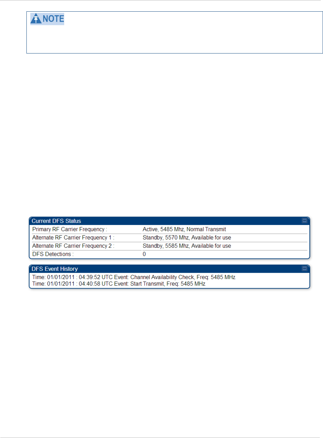
On the AP, the Home => DFS Status page shows current DFS status of all three frequencies
and a DFS log of past DFS events.
Figure 1 AP DFS Status
Background and Operation
The modules use region-specific DFS based on the Country Code selected on the module’s
Configuration, General page. By directing installers and technicians to set the Country Code
correctly, the operator gains confidence the module is operating according to national or regional
regulations without having to deal with the details for each region.
The details of DFS operation for each Country Code, including whether DFS is active on the AP,
SM, and which DFS regulations apply is shown in Table 6 on page 9.
8 pmp-0957 (April 2015)

Compliance with radio regulations PMP 450i and PTP 450i Configuration and User
Guide
Table 6 OFDM DFS operation based on Country Code setting
Country
Code
Band AP SM Weather Radar
Notch-Out
United
States
4.9-GHz No effect No effect No
5.8-GHz No effect No effect No
After an AP with DFS is powered on it performs a channel availability check on its main carrier
frequency for 1 minute, monitoring for the radar signature without transmitting. If no radar
signature is detected during this minute, the module then proceeds to normal beacon transmit
mode. If it does detect a radar signature, the frequency is marked for a 30 minute non-occupancy
period, and the module moves to its 1st alternate carrier frequency. The AP continues this
behavior through its 2nd alternate frequency if needed and then waits until the first frequency
ends the 30 minute non-occupancy period. While operating, if the AP detects a weather radar
signature it marks the current carrier frequency for a 30 minute non-occupancy period and moves
to check the next-in-line carrier frequency.
An SM does not begin transmission until it detects a beacon from an AP. If APs are not
transmitting, SMs will be silent.
Europe applies the ETSI specification to both APs and SMs, while Brazil applies it only to APs. In
the ETSI case, when an SM is powered on, it scans to find a Canopy beacon from a AP. If an AP is
found, the SM performs a channel availability check on that frequency for 1 minute, monitoring
for the radar signature, without transmitting. A DFS decision is made based on the following:
• If no radar pulse is detected during this 1 minute, the SM proceeds through normal steps to
register to an AP.
• If the SM does detect radar, it locks out that frequency for 30 minutes and continues
scanning other frequencies in its scan list.
After an SM with DFS has seen a radar signature on a frequency and locked out that frequency, it
may connect to a different AP if color codes, AP transmitting frequencies, and SM scanned
frequencies support that connection.
To simplify operation and ensure compliance, an SM takes on the DFS type of the AP to which it
registers. For example, when an SM in Europe registers to an AP with the Country Code set to
“United Kingdom”, that SM will use ETSI DFS, no matter what its Country Code is set to, even if
its Country Code is set to “None”. Note, the operator should still configure the Country Code in
the SM correctly, as future releases may use the Country Code for additional region-specific
options.
For all modules running DFS, the module displays its DFS state on its Home => General Status
page as one of the following:
• Checking Channel Availability Remaining time n seconds, where n counts down from
60 to 1.
• Normal Transmit
pmp-0957 (April 2015) 9

PMP 450i and PTP 450i Configuration and User
Compliance with radio regulations
• Radar Detected Stop Transmitting for n minutes, where n counts down from 30 to 1.
• Idle, only for SM/BHS, indicates module is scanning, but has not detected a beacon from an
AP/BHM. Once it detects beacon, the SM/BHS begins a Channel Availability Check on that
frequency.
Regulatory Note: A PMP 450i Series AP with a Country Code set to United States will not be
configurable to another Country Code by installers or end users. This is in response to FCC KDB
594280 and ensures that end users and professional installers will not have access to settings
which could allow a radio to be configured to operate in a manner other than that which was
specified in the FCC equipment authorization grant.
Within the United States and its territories the PMP 450i Country Code is pre-configured to
United States and not selectable in the Configuration, General web page. Radios sold in regions
outside of the United States and its territories are required to set the Country Code to the region
in which it is used.
FCC IDs and certification numbers
Table 7 US FCC IDs Numbers and Covered Configurations
FCC ID Frequency
band Frequencies (MHz)
Antenna Maximum
Combined
Tx Output
Power (dBm)
QWP-50450I
4.9 GHz
Part 90Y
5 MHz: 4942.5 to 4987.5
10 MHz: 4945 to 4985
20 MHz: 4950 to 4980
Omni 24.00
Sector 24.75
Flat plate
directional 24.75
4ft parabolic 23.75
6ft parabolic 22.25
5.8 GHz
FCC Parts
15.207, 15.209
& 15.247
5 MHz: 5730 to 5845
10 MHz: 5730 to 5845
20 MHz: 5735 to 5840
40 MHz: 5747 to 5828
Omni 24.5
Sector 20.75
Flat plate
directional 28.0
4ft parabolic 28.0
6ft parabolic 28.0
10 pmp-0957 (April 2015)

PMP 450i and PTP 450i Configuration and User Guide
Chapter 2: Configuration
This chapter describes all configuration tasks that are performed when a PMP 450i link is
deployed.
Observe the precautions in Preparing for configuration on page 12.
This section is divided into several tasks, including:
• Task 1: Connecting to the unit on page 13
• Task 2: Configuring IP and Ethernet interfaces on page 19
• Task 3: Upgrading the software version and using CNUT on page 56
• Task 4: Configuring General and Unit settings on page 61
• Task 5: Configuring security on page 79
• Task 6: Configuring radio parameters on page 109
• Task 7: Setting up SNMP agent on page 134
• Task 8: Configuring syslog on page 144.
• Task 9: Configuring remote access on page 148
• Task 10: Monitoring the AP-SM Link on page 151
• Task 11: Configuring quality of service on page 154
• Task 12: Performing an Sector Wide SA on page 170
• Task 13: Zero Touch Configuration Using DHCP Option 66 on page 176
• Task 14: Configuring Radio via config file on page 182
• Task 15: Configuring a RADIUS server on page 184

PMP 450i and PTP 450i Configuration and User
Preparing for configuration
Preparing for configuration
This section describes the checks to be performed before proceeding with unit
configuration.
Safety precautions during configuration
All national and local safety standards must be followed while configuring the units
and aligning the antennas.
Ensure that personnel are not exposed to unsafe levels of RF energy. The
units start to radiate as soon as they are powered up.
Observe the following guidelines:
• Do not work in front of the antenna when the AP or SM is powered on.
• Always power down the AP or SM before connecting or disconnecting the drop cable
from the unit.
12 pmp-0957 (April 2015)
Task 1: Connecting to the unit PMP 450i and PTP 450i Configuration and User
Guide
Task 1: Connecting to the unit
This task consists of the following procedures:
• Configuring the management PC on page 13
• Connecting to the PC and powering up on page 15
• Logging into the web interface on page 15
Configuring the management PC
To configure the local management PC to communicate with the PMP 450i AP or SM,
follow these instructions:
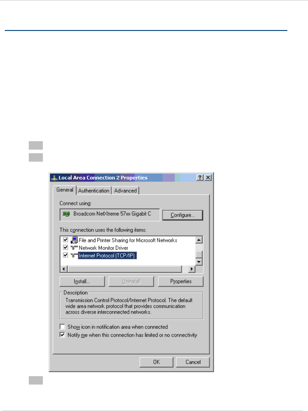
Procedure 1 Configuring the management PC
1 Click Properties for the Ethernet port.
2 Select the Internet Protocol (TCP/IP) item (in Windows 7, this item is called
“Internet Protocol Version 4 (TCP/IPv4)”:
3 Click on Properties.
pmp-0957 (April 2015) 13
PMP 450i and PTP 450i Configuration and User
Task 1: Connecting to the unit
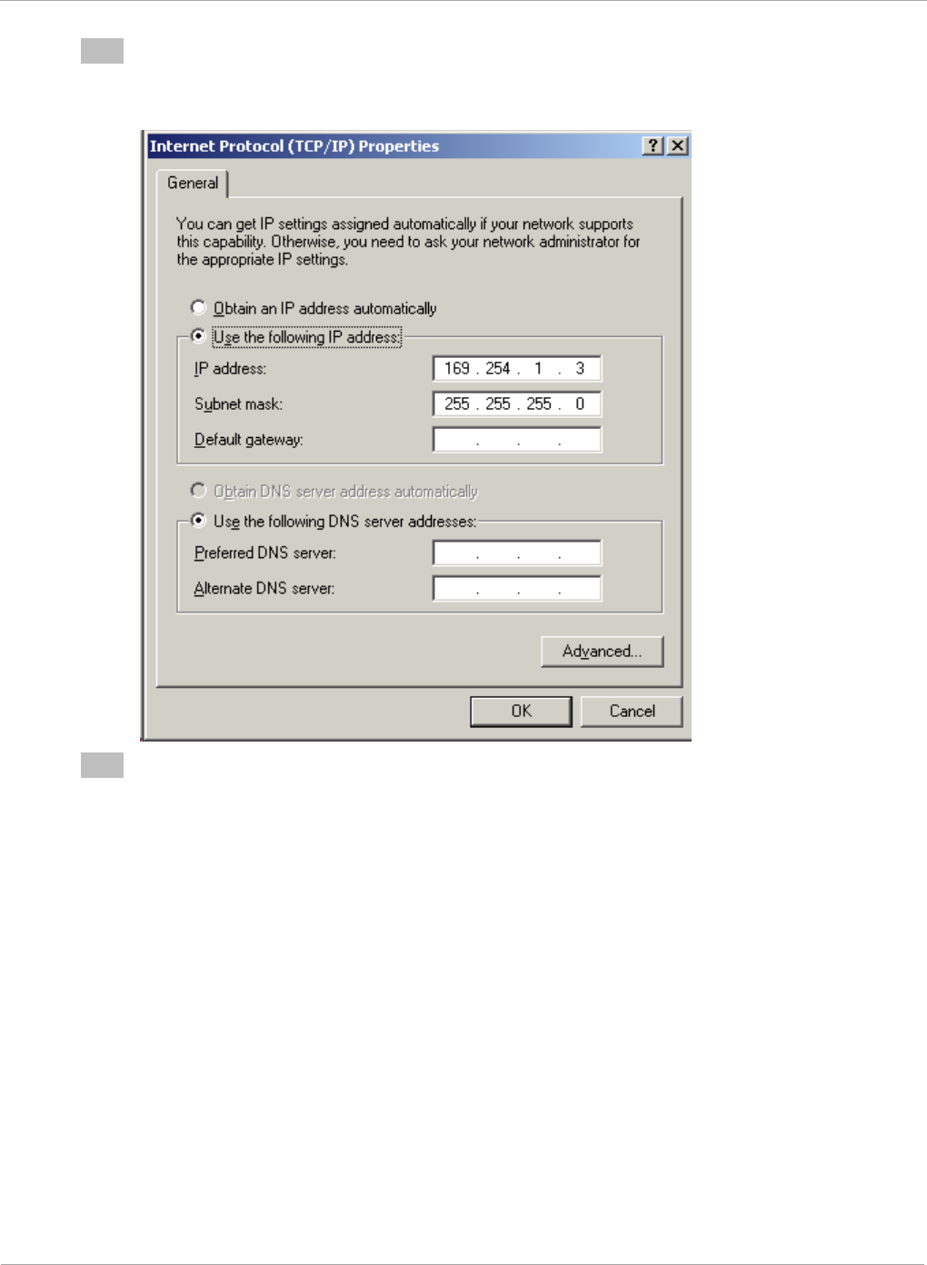
4 Enter an IP address that is valid for the 169.254.X.X network, avoiding:
169.254.0.0 and 169.254.1.1 and 169.254.1.2
A good example is 169.254.1.3:
5 Enter a subnet mask of 255.255.255.0.
Leave the default gateway blank.
14 pmp-0957 (April 2015)
Task 1: Connecting to the unit PMP 450i and PTP 450i Configuration and User
Guide
Connecting to the PC and powering up
To connect the PMP 450i AP or SM to the PC and power up the unit, follow these
instructions:
Procedure 2 Connecting to the PC and powering up
1 Check that the AP or SM and the associated power supply are correctly
connected.
2 Connect the PC Ethernet port to the LAN port of the power supply using a
standard (not crossed) Ethernet cable.
3 Apply power to the radio power supply. The green Power LED must illuminate
continuously.
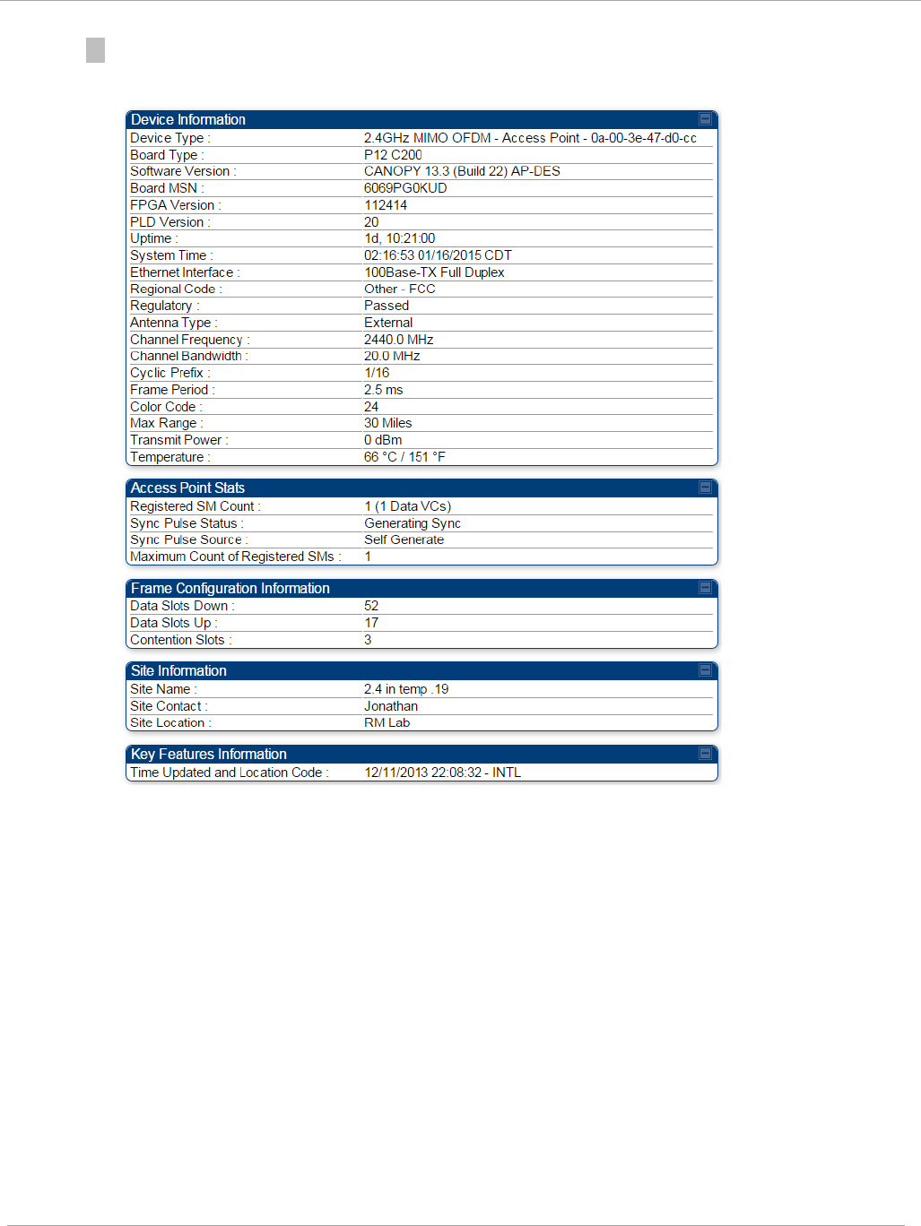
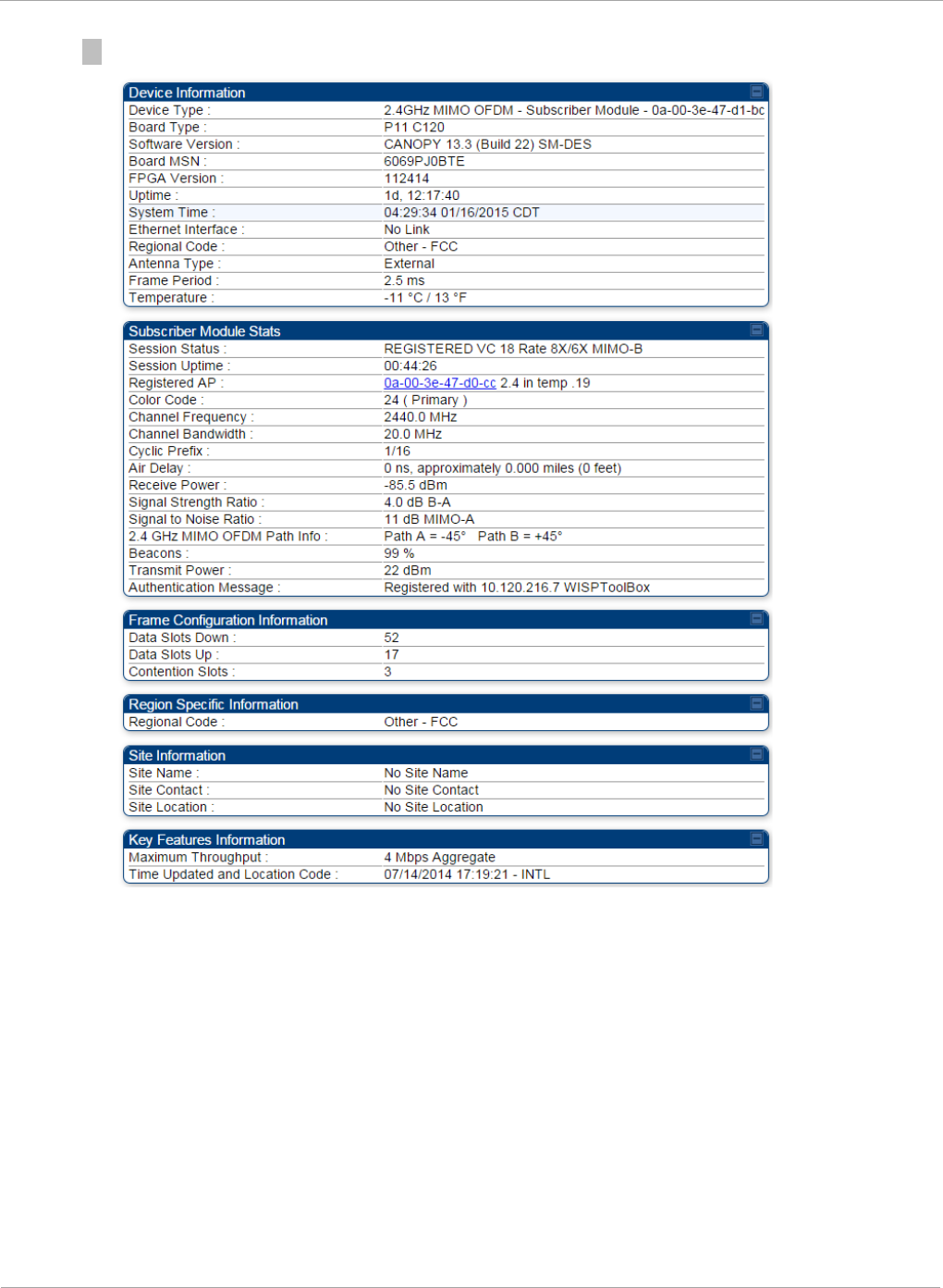
Logging into the web interface (AP or SM)
To log into the AP or SM web interface as a system administrator, follow these
instructions:
Procedure 3 Logging into the web interface (AP or SM)
1 Start the web browser from the management PC.
2 Type the IP address of the unit into the address bar and press ENTER (Default IP
address is 169.254.1.1).
The web interface General Status page is displayed:
The below General Status is displayed when "Site Information Viewable to
Guest Users" is "Enabled".
pmp-0957 (April 2015) 15
PMP 450i and PTP 450i Configuration and User
Task 1: Connecting to the unit
Figure 2 AP General Status page, GUEST user example
Figure 3 SM General Status page, GUEST user example
16 pmp-0957 (April 2015)
Task 1: Connecting to the unit PMP 450i and PTP 450i Configuration and User
Guide
3 Log in with the
default
administrator Username (
admin
) and Password (
admin
).
Figure 4 AP General Status page, ADMINISTRATOR user example
pmp-0957 (April 2015) 17
PMP 450i and PTP 450i Configuration and User
Task 1: Connecting to the unit
Figure 5 SM General Status page, ADMINISTRATOR user example
18 pmp-0957 (April 2015)
Task 2: Configuring IP and Ethernet interfaces PMP 450i and PTP 450i Configuration and User
Guide
Task 2: Configuring IP and Ethernet interfaces
This task consists of the following sections:
• Configuring the AP IP interface on page 19
• NAT, DHCP Server, DHCP Client and DMZ in SM on page 22
• Configuring the SM IP interface with NAT disabled on page 26
• Configuring the SM IP interface with NAT enabled on page 29
• NAT tab of the SM with NAT disabled on page 30
• NAT tab of the SM with NAT enabled on page 34
• SM NAT DNS Considerations on page 40
• Reconnecting to the management PC on page 40
• VLAN Remarking and Priority bits configuration on page 41
• VLAN tab of the AP on page 43
• VLAN tab of the SM on page 46
• VLAN Membership tab of the SM on page 51
• PPPoE tab of the SM on page 51
• NAT Port Mapping tab of the SM on page 55
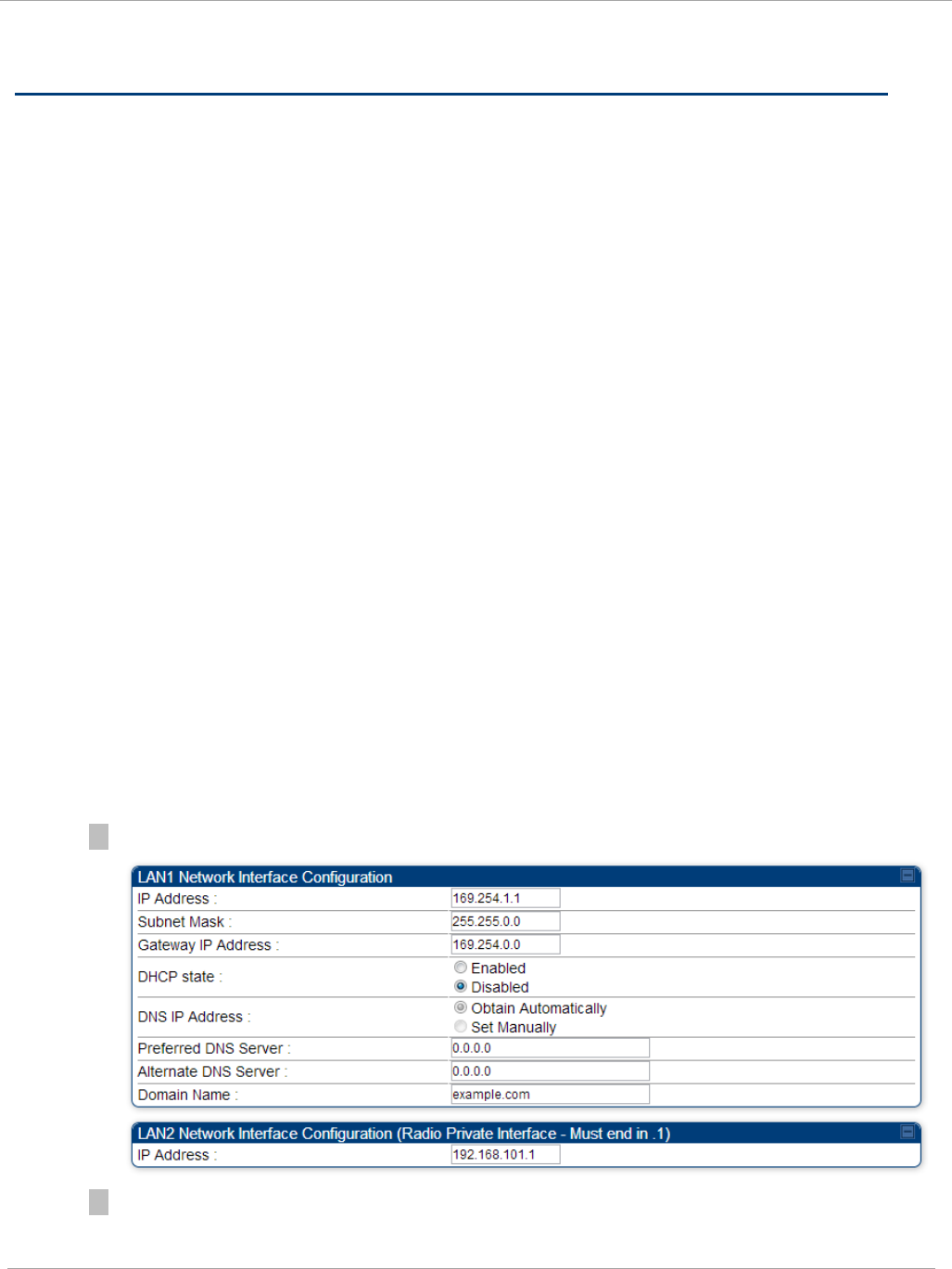
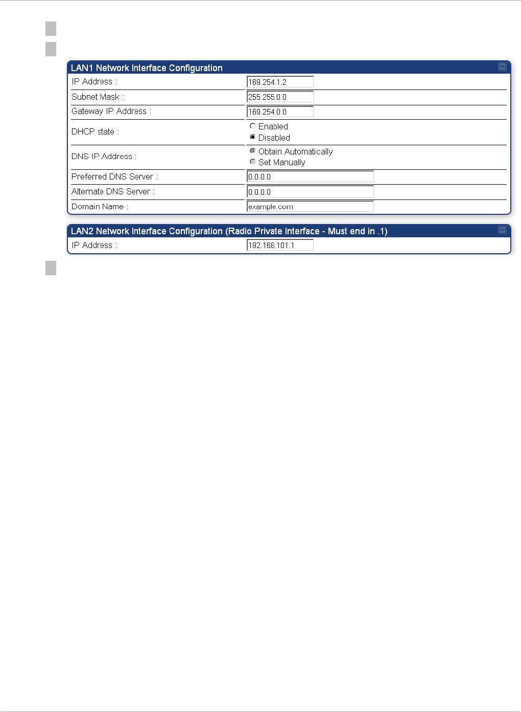
Configuring the AP IP interface
The IP interface allows users to connect to the PMP 450i web interface, either from
a locally connected computer or from a management network.
To configure the IP interface, follow these instructions:
Procedure 4 Configuring the AP IP interface
1 Select menu option Configuration => IP. The LAN configuration page is displayed:
2 Update IP Address, Subnet Mask and Gateway IP Address to meet network
requirements (as specified by the network administrator).
pmp-0957 (April 2015) 19

Task 2: Configuring IP and Ethernet interfaces PMP 450i and PTP 450i Configuration and User
Guide
Table 8 IP interface attributes
Attribute Meaning
IP Address Internet Protocol (IP) address. This address is used by family of
Internet protocols to uniquely identify this unit on a network.
Subnet Mask Defines the address range of the connected IP network.
Gateway IP
Address
The IP address of a computer on the current network that acts
as a gateway. A gateway acts as an entrance and exit to
packets from and to other networks.
DHCP state If Enabled is selected, the DHCP server automatically assigns
the IP configuration (IP address, subnet mask, and gateway IP
address) and the values of those individual parameters (above)
are not used. The setting of this DHCP state parameter is also
viewable (read only), in the Network Interface tab of the Home
page.
DNS IP Address Canopy devices allow for configuration of a preferred and
alternate DNS server IP address either automatically or
manually. Devices must set DNS server IP address manually
when DHCP is disabled for the management interface of the
device. DNS servers may be configured automatically from the
DHCP response when DHCP is enabled for the management
interface of the device. Optionally devices may be configured to
set the DNS server IP address manually when DHCP is enabled
for the management interface. The default DNS IP addresses
are 0.0.0.0 when configured manually.
Preferred DNS
Server
The first address used for DNS resolution.
Alternate DNS
Server
If the Preferred DNS server cannot be reached, the Alternate
DNS Server is used.
Domain Name The operator’s management domain name may be configured
for DNS. The domain name configuration can be used for
configuration of the servers in the operator’s network. The
default domain name is example.com, and is only used if
configured as such.
LAN2 Network
Interface
Configuration
(Radio Private
Interface) – IP
Address
It is recommended not to change this parameter from the
default
AP
private IP address of 192.168.101.1. A /24 CIDR
subnet is used to communicate with each of the SMs that are
registered. The AP uses a combination of the private IP and the
LUID (logical unit ID) of the SM.
SM LUID Private IP
First SM registered
2 192.168.101.2
Second SM
registered
3 192.168.101.3
pmp-0957 (April 2015) 21

PMP 450i and PTP 450i Configuration and User
Task 2: Configuring IP and Ethernet interfaces
NAT, DHCP Server, DHCP Client and DMZ in SM
The system provides NAT (Network Address Translation) for SMs in the following
combinations of NAT and DHCP (Dynamic Host Configuration Protocol):
• NAT Disabled
• NAT with DHCP Client (DHCP selected as the Connection Type of the WAN interface)
and DHCP Server
• NAT with DHCP Client(DHCP selected as the Connection Type of the WAN interface)
• NAT with DHCP Server
• NAT without DHCP
NAT
NAT isolates devices connected to the Ethernet or wired side of a SM from being
seen directly from the wireless side of the SM. With NAT enabled, the SM has an IP
address for transport traffic (separate from its address for management), terminates
transport traffic and allows you to assign a range of IP addresses to devices that are
connected to the Ethernet or wired side of the SM.
In the Cambium system, NAT supports many protocols, including HTTP, ICMP
(Internet Control Message Protocols), and FTP (File Transfer Protocol). For virtual
private network (VPN) implementation, L2TP over IPSec (Level 2 Tunneling Protocol
over IP Security) and PPTP (Point to Point Tunneling Protocol) are supported.
When NAT is enabled, a reduction in throughput is introduced in the system (due
to processing overhead).
DHCP
DHCP enables a device to be assigned a new IP address and TCP/IP parameters,
including a default gateway, whenever the device reboots. Thus DHCP reduces
configuration time, conserves IP addresses, and allows modules to be moved to a
different network within the Cambium system.
In conjunction with the NAT features, each SM provides the following:
• A DHCP server that assigns IP addresses to computers connected to the SM by
Ethernet protocol.
• A DHCP client that receives an IP address for the SM from a network DHCP server.
DMZ
In conjunction with the NAT features, a DMZ (Demilitarized Zone) allows the
allotment of one IP address behind the SM for a device to logically exist outside the
firewall and receive network traffic. The first three octets of this IP address must be
identical to the first three octets of the NAT private IP address.
22 pmp-0957 (April 2015)
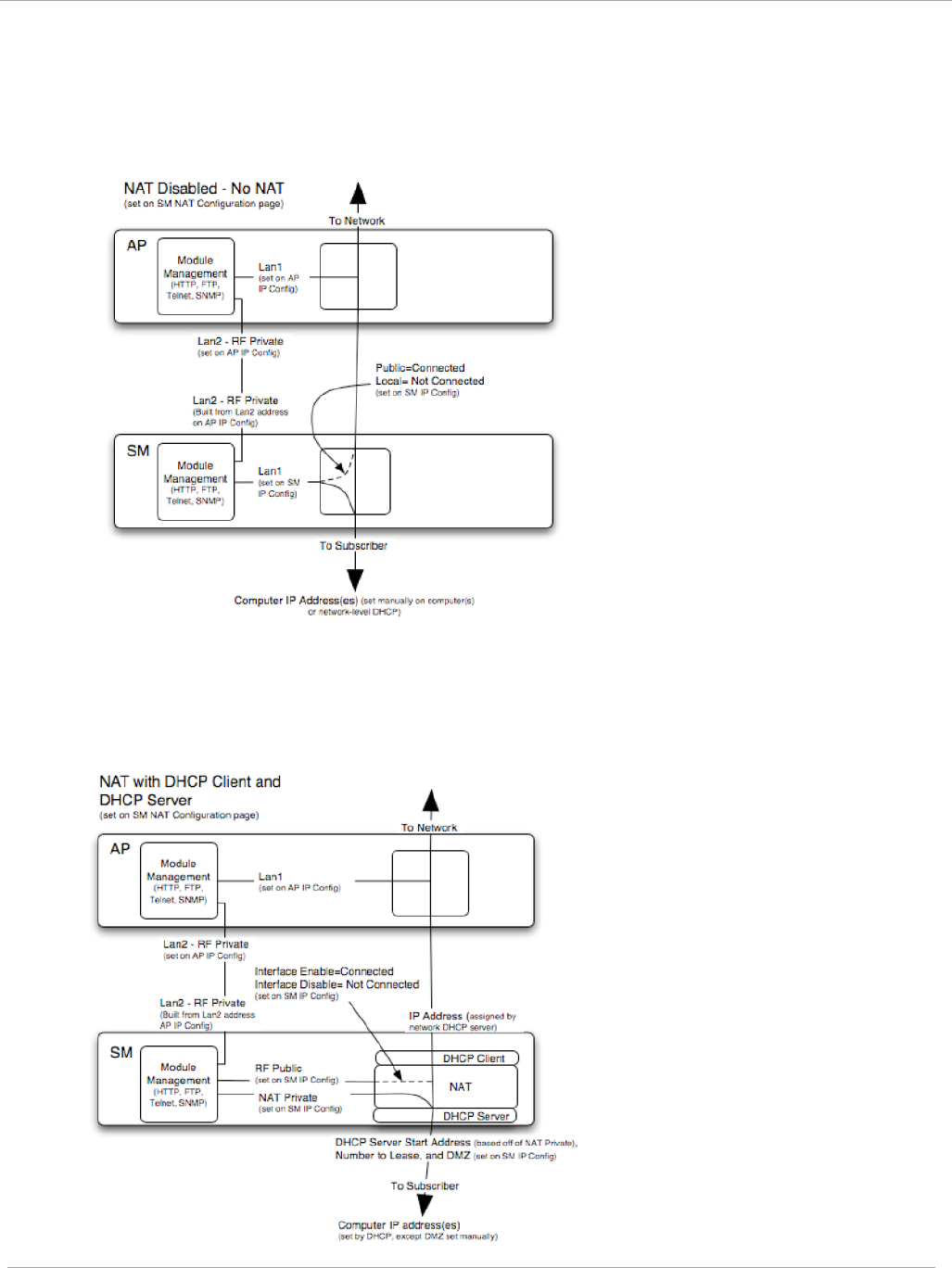
Task 2: Configuring IP and Ethernet interfaces PMP 450i and PTP 450i Configuration and User
Guide
NAT Disabled
The NAT Disabled implementation is illustrated in Figure 6.
Figure 6 NAT disabled implementation
NAT with DHCP Client and DHCP Server
The NAT with DHCP Client and DHCP server is illustrated in Figure 7.
Figure 7 NAT with DHCP client and DHCP server implementation
pmp-0957 (April 2015) 23
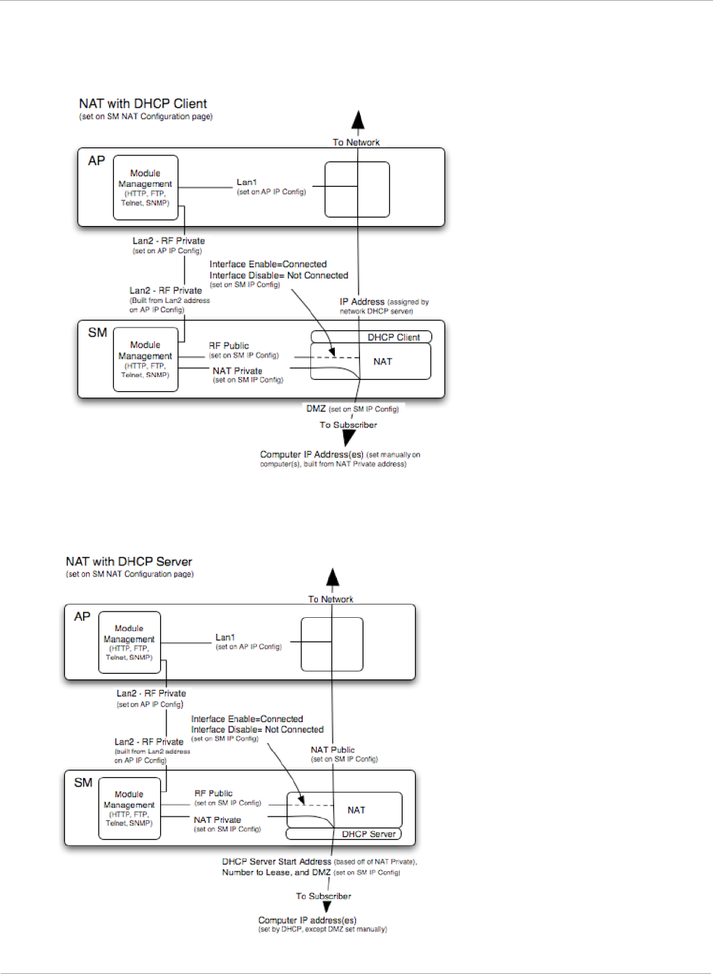
PMP 450i and PTP 450i Configuration and User
Task 2: Configuring IP and Ethernet interfaces
NAT with DHCP Client
Figure 8 NAT with DHCP client implementation
NAT with DHCP Server
Figure 9 NAT with DHCP server implementation
24 pmp-0957 (April 2015)
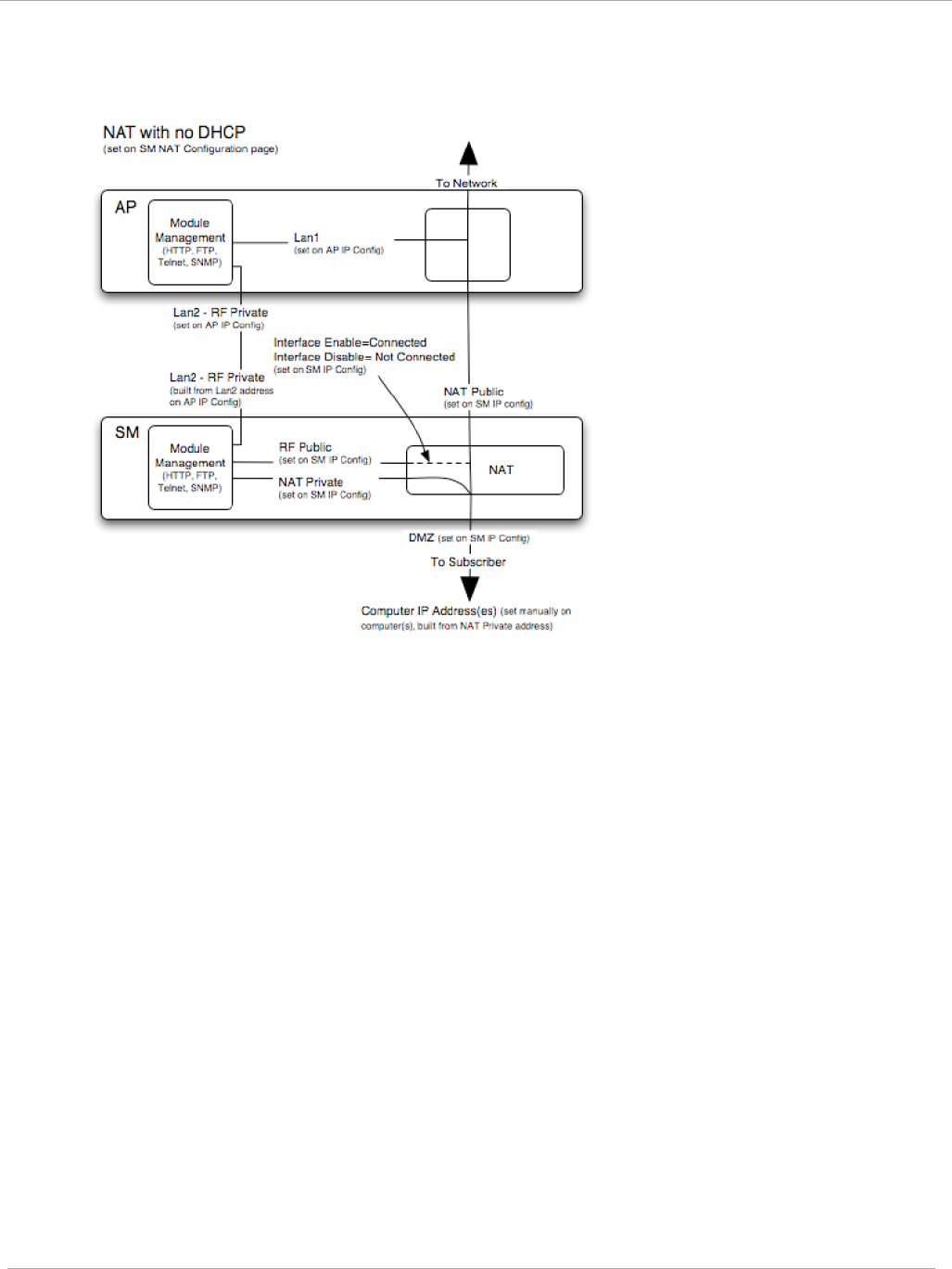
Task 2: Configuring IP and Ethernet interfaces PMP 450i and PTP 450i Configuration and User
Guide
NAT without DHCP
Figure 10 NAT without DHCP implementation
NAT and VPNs
VPN technology provides the benefits of a private network during communication
over a public network. One typical use of a VPN is to connect employees remotely
(who are at home or in a different city), with their corporate network through a
public Internet. Any of several VPN implementation schemes is possible. By design,
NAT translates or changes addresses, and thus interferes with a VPN that is not
specifically supported by a given NAT implementation.
With NAT enabled, SMs support L2TP over IPSec (Level 2 Tunneling Protocol over
IP Security) VPNs and PPTP (Point to Point Tunneling Protocol) VPNs. With NAT
disabled, SMs support all types of VPNs.
pmp-0957 (April 2015) 25
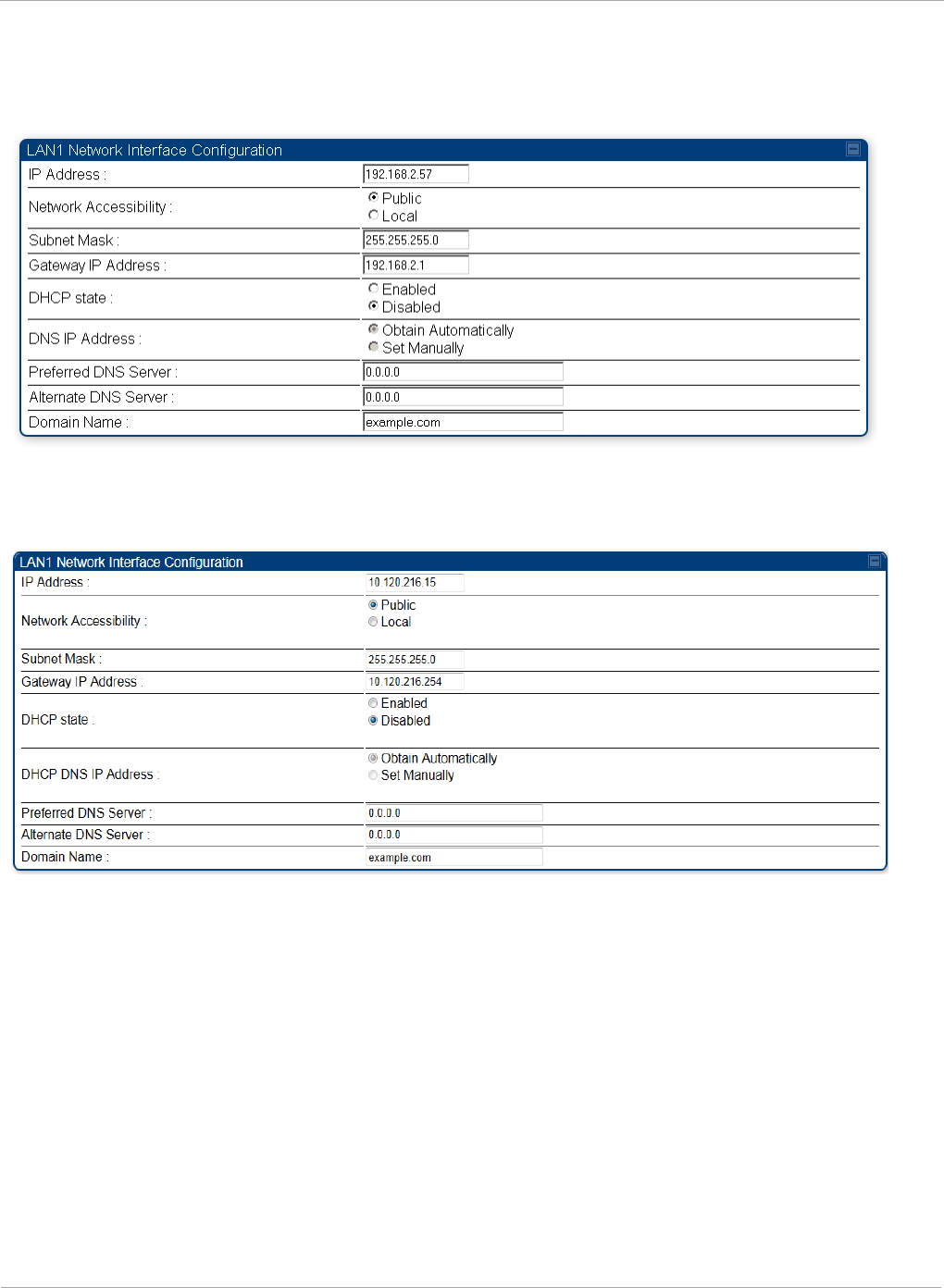
PMP 450i and PTP 450i Configuration and User
Task 2: Configuring IP and Ethernet interfaces
Configuring the SM IP interface with NAT disabled
Figure 11 IP tab of the SM with NAT disabled
The IP tab of SM with NAT disabled is as shown in Figure 12. User may set the parameters
as explained in Table 9.
Figure 12 IP tab of SM
26 pmp-0957 (April 2015)

Task 2: Configuring IP and Ethernet interfaces PMP 450i and PTP 450i Configuration and User
Guide
Table 9 SM with NAT disabled - IP attributes
Attribute Meaning
IP Address
Enter the
non-routable
IP address to associate with the
Ethernet connection on this SM. (The default IP address
from the factory is 169.254.1.1.) If you forget this
parameter, you must both:
• physically access the module.
• use an override plug to electronically access the
module configuration parameters at 169.254.1.1. See
Overriding Forgotten IP Addresses or Passwords on
AP on Page 83.
Note or print the IP settings from this page. Ensure
that you can readily associate these IP settings both
with the module and with the other data that you
store about the module.
Network Accessibility Specify whether the IP address of the SM must be
visible to only a device connected to the SM by Ethernet
(Local) or be visible to the AP as well (Public).
Subnet Mask Enter an appropriate subnet mask for the SM to
communicate on the network. The default subnet mask
is 255.255.0.0.
Gateway IP Address Enter the appropriate gateway for the SM to
communicate with the network. The default gateway is
169.254.0.0.
pmp-0957 (April 2015) 27

PMP 450i and PTP 450i Configuration and User
Task 2: Configuring IP and Ethernet interfaces
Attribute Meaning
DHCP state
If you select Enabled, the DHCP server automatically
assigns the IP configuration (IP address, subnet mask,
and gateway IP address) and the values of those
individual parameters (above) are not used. The setting
of this DHCP state parameter is also viewable, but not
settable, in the Network Interface tab of the Home page.
In this tab, DHCP State is settable only if the
Network Accessibility parameter in the IP tab is set to
Public. This parameter is also settable in the NAT tab of
the Configuration web page, but only when NAT is
enabled.
If the DHCP state parameter is set to Enabled in the
Configuration => IP tab of the SM,
do not
check the
BootpClient option for Packet Filter Types in its
Protocol Filtering tab, because doing so can block the
DHCP request. (Filters apply to all packets that leave
the SM via its RF interface, including those that the SM
itself generates.) If you want to keep DHCP enabled and
avoid the blocking scenario, select the Bootp Server
option instead. This will result in responses being
appropriately filtered and discarded.
DHCP DNS IP Address Canopy devices allow for configuration of a preferred
and alternate DNS server IP address either
automatically or manually. Devices must set DNS server
IP address manually when DHCP is disabled for the
management interface of the device. DNS servers may
be configured automatically from the DHCP response
when DHCP is enabled for the management interface of
the device. Optionally devices may be configured to set
the DNS server IP address manually when DHCP is
enabled for the management interface. The default DNS
IP addresses are 0.0.0.0 when configured manually.
Preferred DNS Server The first DNS server used for DNS resolution.
Alternate DNS Server The second DNS server used for DNS resolution.
Domain Name The operator’s management domain name may be
configured for DNS. The domain name configuration can
be used for configuration of the servers in the operator’s
network. The default domain name is example.com, and
is only used if configured as such.
28 pmp-0957 (April 2015)

Task 2: Configuring IP and Ethernet interfaces PMP 450i and PTP 450i Configuration and User
Guide
Configuring the SM IP interface with NAT enabled
Figure 13 IP tab of SM with NAT enabled
In the IP tab of SM with NAT enabled, you may set the following parameters.
Table 10 SM with NAT enabled - IP attributes
Attribute Meaning
IP Address
Assign an IP address for SM management through Ethernet access
to the SM. Set only the first three bytes. The last byte is permanently
set to 1. This address becomes the base for the range of DHCP-
assigned addresses.
Subnet
Mask
Assign a subnet mask of 255.255.255.0 or a more restrictive subnet
mask. Set only the last byte of this subnet mask. Each of the first
three bytes is permanently set to 255.
pmp-0957 (April 2015) 29
PMP 450i and PTP 450i Configuration and User
Task 2: Configuring IP and Ethernet interfaces
NAT tab of the SM with NAT disabled
In the NAT tab of a SM with NAT disabled, you may set the following parameters.
Figure 14 SM with NAT disabled
30 pmp-0957 (April 2015)

Task 2: Configuring IP and Ethernet interfaces PMP 450i and PTP 450i Configuration and User
Guide
Table 11 SM with NAT disabled - NAT attributes
Attribute Meaning
NAT Enable/Disable This parameter enables or disables the Network Address
Translation (NAT) feature for the SM. NAT isolates
devices connected to the Ethernet or wired side of a SM
from being seen directly from the wireless side of the
SM. With NAT enabled, the SM has an IP address for
transport traffic separate from its address for
management, terminates transport traffic, and allows
you to assign a range of IP addresses to devices that are
connected to the Ethernet or wired side of the SM
When NAT is enabled, VLANs are not supported on the
wired side of that SM. You can enable NAT in SMs
within a sector where VLAN is enabled in the AP, but
this may constrain network design.
When NAT is enabled, a reduction in throughput is
introduced at the SM (due to processing overhead).
Connection Type This parameter is not configurable when NAT is
disabled.
IP Address This field displays the IP address for the SM. DHCP
Server
will not
automatically assign this address when
NAT is disabled.
Subnet Mask This field displays the subnet mask for the SM. DHCP
Server
will not
automatically assign this address when
NAT is disabled.
Gateway IP Address This field displays the gateway IP address for the SM.
DHCP Server
will not
automatically assign this address
when NAT is disabled.
Reply to Ping on WAN
Interface
This parameter is not configurable when NAT is
disabled.
IP Address This parameter is not configurable when NAT is
disabled.
Subnet Mask This parameter is not configurable when NAT is
disabled.
DMZ Enable This parameter is not configurable when NAT is
disabled.
DMZ IP Address This parameter is not configurable when NAT is
disabled.
pmp-0957 (April 2015) 31

PMP 450i and PTP 450i Configuration and User
Task 2: Configuring IP and Ethernet interfaces
Attribute Meaning
DHCP Server
Enable/Disable
This parameter is not configurable when NAT is
disabled.
DHCP Server Lease
Timeout
This parameter is not configurable when NAT is
disabled.
DHCP Start IP This parameter is not configurable when NAT is
disabled.
Number of IPs to Lease This parameter is not configurable when NAT is
disabled.
DNS Server Proxy This parameter is not configurable when NAT is
disabled.
DNS IP Address This parameter is not configurable when NAT is
disabled.
Preferred DNS IP
Address
This parameter is not configurable when NAT is
disabled.
Alternate DNS IP
Address
This parameter is not configurable when NAT is
disabled.
Remote Management
Interface
This parameter is not configurable when NAT is
disabled.
Connection Type This parameter is not configurable when NAT is
disabled.
IP Address This parameter is not configurable when NAT is
disabled.
Subnet Mask This parameter is not configurable when NAT is
disabled.
Gateway IP Address This parameter is not configurable when NAT is
disabled.
DNS IP Address This parameter is not configurable when NAT is
disabled.
Preferred DNS Server This parameter is not configurable when NAT is
disabled.
Alternate DNS Server This parameter is not configurable when NAT is
disabled.
Domain Name This parameter is not configurable when NAT is
disabled.
ARP Cache Timeout If a router upstream has an ARP cache of longer
duration (as some use 30 minutes), enter a value of
longer duration than the router ARP cache. The default
value of this field is 20 minutes.
32 pmp-0957 (April 2015)

Task 2: Configuring IP and Ethernet interfaces PMP 450i and PTP 450i Configuration and User
Guide
Attribute Meaning
TCP Session Garbage
Timeout
Where a large network exists behind the SM, you can
set this parameter to lower than the default value of 120
minutes. This action makes additional resources
available for greater traffic than the default value
accommodates.
UDP Session Garbage
Timeout
You may adjust this parameter in the range of 1 to 1440
minutes, based on network performance. The default
value of this parameter is 4 minutes.
Translation Table Size Total number of minutes that have elapsed since the last
packet transfer between the connected device and the
SM.
pmp-0957 (April 2015) 33
PMP 450i and PTP 450i Configuration and User
Task 2: Configuring IP and Ethernet interfaces
NAT tab of the SM with NAT enabled
Figure 15 NAT tab of the SM with NAT enabled
34 pmp-0957 (April 2015)

Task 2: Configuring IP and Ethernet interfaces PMP 450i and PTP 450i Configuration and User
Guide
In the NAT tab of SM with NAT enabled, you may set the following parameters.
Table 12 SM with NAT enabled - NAT attributes
Attribute Meaning
NAT
Enable/Disable
This parameter enables or disabled the Network Address
Translation (NAT) feature for the SM. NAT isolates devices
connected to the Ethernet or wired side of a SM from being
seen directly from the wireless side of the SM. With NAT
enabled, the SM has an IP address for transport traffic
separate from its address for management, terminates
transport traffic, and allows you to assign a range of IP
addresses to devices that are connected to the Ethernet or
wired side of the SM.
When NAT is enabled, VLANs are not supported on the wired
side of that SM. You can enable NAT in SMs within a sector
where VLAN is enabled in the AP, but this may constrain
network design.
WAN Interface The WAN interface is the RF-side address for transport
traffic.
Connection Type
This parameter may be set to
Static IP—when this is the selection, all three parameters
(IP Address, Subnet Mask, and Gateway IP Address) must
be properly populated.
DHCP—when this is the selection, the information from the
DHCP server configures the interface.
PPPoE—when this is the selection, the information from the
PPPoE server configures the interface.
Subnet Mask If Static IP is set as the Connection Type of the WAN
interface, then this parameter configures the subnet mask of
the SM for RF transport traffic.
Gateway IP
Address
If Static IP is set as the Connection Type of the WAN
interface, then this parameter configures the gateway IP
address for the SM for RF transport traffic.
Reply to Ping on
WAN Interface
By default, the radio interface
does not
respond to pings. If
you use a management system (such as WM) that will
occasionally ping the SM, set this parameter to Enabled.
LAN Interface The LAN interface is both the management access through
the Ethernet port and the Ethernet-side address for transport
traffic. When NAT is enabled, this interface is redundantly
shown as the NAT Network Interface Configuration on
the IP tab of the Configuration web page in the SM.
pmp-0957 (April 2015) 35

PMP 450i and PTP 450i Configuration and User
Task 2: Configuring IP and Ethernet interfaces
Attribute Meaning
IP Address Assign an IP address for SM management through Ethernet
access to the SM. This address becomes the base for the
range of DHCP-assigned addresses.
Subnet Mask Assign a subnet mask of 255.255.255.0 or a more restrictive
subnet mask. Set only the last byte of this subnet mask. Each
of the first three bytes is permanently set to 255.
DMZ Enable Either enable or disable DMZ for this SM.
DMZ IP Address If you enable DMZ in the parameter above, set the last byte
of the DMZ host IP address to use for this SM when DMZ is
enabled. Only one such address is allowed. The first three
bytes are identical to those of the NAT private IP address.
Ensure that the device that receives network traffic behind
this SM is assigned this address. The system provides a
warning if you enter an address within the range that DHCP
can assign.
DHCP Server This is the server (in the SM) that provides an IP address to
the device connected to the Ethernet port of the SM.
DHCP Server
Enable/Disable
Select either
Enabled
or
Disabled
.
Enable to:
• Allow this SM to assign IP addresses, subnet masks, and
gateway IP addresses to attached devices.
• Assign a start address for DHCP.
• Designate how many IP addresses may be temporarily
used (leased).
Disable to:
• Restrict SM from assigning addresses to attached
devices.
DHCP Server Lease
Timeout
Based on network performance, enter the number of days
between when the DHCP server assigns an IP address and
when that address expires. The range of values for this
parameter is 1 to 30 days. The default value is 30 days.
DHCP Start IP If you enable DHCP Server below, set the last byte of the
starting IP address that the DHCP server assigns. The first
three bytes are identical to those of the NAT private IP
address.
Number of IPs to
Lease
Enter how many IP addresses the DHCP server is allowed to
assign. The default value is 50 addresses.
36 pmp-0957 (April 2015)

Task 2: Configuring IP and Ethernet interfaces PMP 450i and PTP 450i Configuration and User
Guide
Attribute Meaning
DNS Server Proxy This parameter enables or disables advertisement of the SM
as the DNS server. On initial boot up of a SM with the NAT
WAN interface configured as DHCP or PPPoE, the SM
module will not have DNS information immediately. With
DNS Server Proxy disabled, the clients will renew their
lease about every minute until the SM has the DNS
information to give out. At this point the SM will go to the
full configured lease time period which is 30 days by default.
With DNS Server Proxy enabled, the SM will give out full
term leases with its NAT LAN IP as the DNS server.
DNS IP Address
Select either:
Obtain Automatically to allow the system to set the IP
address of the DNS server
or
Set Manually to enable yourself to set both a preferred and
an alternate DNS IP address.
Preferred DNS IP
Address
Enter the preferred DNS IP address to use when the DNS IP
Address parameter is set to Set Manually.
Alternate DNS IP
Address
Enter the DNS IP address to use when the DNS IP Address
parameter is set to Set Manually and no response is
received from the preferred DNS IP address.
pmp-0957 (April 2015) 37

PMP 450i and PTP 450i Configuration and User
Task 2: Configuring IP and Ethernet interfaces
Attribute Meaning
Remote
Management
Interface
To offer greater flexibility in IP address management, the
NAT-enabled SM’s configured WAN Interface IP address may
now be used as the device Remote Management Interface
(unless the SM’s PPPoE client is set to Enabled)
Disable: When this interface is set to “Disable”, the SM is
not directly accessible by IP address. Management access is
only possible through either the LAN (Ethernet) interface or
a link from an AP web page into the WAN (RF-side) interface.
Enable (Standalone Config): When this interface is set to
“Enable (Standalone Config)”, to manage the SM the device
must be accessed by the IP addressing information provided
in the Remote Configuration Interface section.
When configuring PPPoE over the link, use this
configuration option (PPPoE traffic is routed via the IP
addressing specified in section Remote Configuration
Interface).
Enable (Use WAN Interface): When this interface is set to
“Enable (Use WAN Interface)”, the Remote Configuration
Interface information is greyed out, and the SM is managed
via the IP addressing specified in section WAN Interface).
When using this configuration, the ports defined in
section Configuration, Port Configuration are consumed
by the device. For example, if FTP Port is configured as
21 by the SM, an FTP server situated below the SM must
use a port other than 21. This also applies to DMZ
devices; any ports specified in section Configuration, Port
Configuration will not be translated through the NAT,
they is consumed by the device’s network stack for
management.
Connection Type
This parameter can be set to:
Static IP—when this is the selection, all three parameters
(IP Address, Subnet Mask, and Gateway IP Address) must
be properly populated.
DHCP—when this is the selection, the information from the
DHCP server configures the interface.
IP Address
If Static IP is set as the Connection Type of the WAN
interface, then this parameter configures the IP address of
the SM for RF management traffic.
38 pmp-0957 (April 2015)

Task 2: Configuring IP and Ethernet interfaces PMP 450i and PTP 450i Configuration and User
Guide
Attribute Meaning
Subnet Mask
If Static IP is set as the Connection Type of the WAN
interface, then this parameter configures the subnet mask of
the SM for RF management traffic.
Gateway IP
Address
If Static IP is set as the Connection Type of the WAN
interface, then this parameter configures the gateway IP
address for the SM for RF management traffic.
Note or print the IP settings from this page. Ensure that you
can readily associate these IP settings both with the module
and with the other data that you store about the module.
DHCP DNS IP
Address
Select either:
Obtain Automatically to allow the system to set the IP
address of the DNS server.
or
Set Manually to enable yourself to set both a preferred and
an alternate DNS IP address.
Preferred DNS
Server
Enter the preferred DNS IP address to use when the DNS IP
Address parameter is set to Set Manually.
Alternate DNS
Server
Enter the DNS IP address to use when the DNS IP Address
parameter is set to Set Manually and no response is
received from the preferred DNS IP address.
Domain Name Domain Name to use for management DNS configuration.
This domain name may be concatenated to DNS names used
configured for the remote configuration interface.
ARP Cache Timeout If a router upstream has an ARP cache of longer duration (as
some use 30 minutes), enter a value of longer duration than
the router ARP cache. The default value of this field is
20
(minutes).
TCP Session
Garbage Timeout
Where a large network exists behind the SM, you can set this
parameter to lower than the default value of
120
(minutes).
This action makes additional resources available for greater
traffic than the default value accommodates.
UDP Session
Garbage Timeout
You may adjust this parameter in the range of 1 to 1440
minutes, based on network performance. The default value of
this parameter is
4
(minutes).
pmp-0957 (April 2015) 39

PMP 450i and PTP 450i Configuration and User
Task 2: Configuring IP and Ethernet interfaces
SM NAT DNS Considerations
SM DNS behavior is different depending on the accessibility of the SM. When NAT
is enabled the DNS configuration that is discussed in this document is tied to the RF
Remote Configuration Interface, which must be enabled to utilize DNS Client
functionality. Note that the WAN DNS settings when NAT is enabled are unchanged
with the addition of the management DNS feature discussed in this document.
Table 13 SM DNS Options with NAT Enabled
NAT
Configuration
Management
Interface
Accessibility
DHCP Status DNS Status
NAT Enabled
RF Remote
Management
Interface Disabled
N/A DNS Disabled
RF Remote
Management
Interface Enabled
DHCP
Disabled
DNS Static
Configuration
DHCP
Enabled
DNS from DHCP or
DNS Static
Configuration
Reconnecting to the management PC
If the IP Address, Subnet Mask and Gateway IP Address of the unit have been updated to
meet network requirements, then reconfigure the local management PC to use an IP
address that is valid for the network. See Configuring the management PC on page 13.
Once the unit reboots, log in using the new IP address. See Logging into the web interface
on page 15.
40 pmp-0957 (April 2015)

Task 2: Configuring IP and Ethernet interfaces PMP 450i and PTP 450i Configuration and User
Guide
VLAN Remarking and Priority bits configuration
VLAN Remarking
VLAN Remarking feature allows the user to change the VLAN ID and priority of both
upstream and downstream packets at the Ethernet Interface. The remarking
configuration is available for:
1. VLAN ID re-marking
2. 802.1p priority re-marking
For Q-in-Q VLAN tagged frame, re-marking is performed on the
outer tag.
VLAN ID Remarking
SM supports the ability to re-mark the VLAN ID on both upstream and downstream VLAN
frames at the Ethernet interface. For instance, a configuration can be added to re-mark
VLAN ID ‘x’ to VLAN ID ‘y’ as shown in Table 14. AP does not support VLAN ID
remarking.
Table 14 VLAN Remarking Example
VLAN frame direction
Remarking
Upstream
SM receives VLAN ID ‘x’ frame at the Ethernet interface,
checks the configuration and re-marks to VLAN ID ‘y’. So
VLAN ID ‘y’ frame comes out of AP’s Ethernet interface.
When SM re-marks, a dynamic entry in VLAN membership
table for ‘y’ is added to allow reception of VLAN ID ‘y’
Downstream
AP receives VLAN ID ‘y’ frame at the Ethernet interface and
sends to SM. SM accepts the frame as it has an entry in the
membership table and re-marks to VLAN ID ‘x’. This reverse
re- marking is necessary because the downstream devices do
not know of re-marking and are expecting VLAN ‘x’ frames.
802.1P Remarking
AP and SM allow re-marking of 802.1p priority bits for the frames received at the Ethernet
interface. Priority bits are not re-marked for the packets sent out of Ethernet interface
(reverse direction).
Configuration must be added at SM for upstream frames and at AP for downstream frames.
pmp-0957 (April 2015) 41

PMP 450i and PTP 450i Configuration and User
Task 2: Configuring IP and Ethernet interfaces
VLAN Priority Bits configuration
VLAN Priority Bits Configuration feature allows the user to configure the three 802.1p
bits upon
assigning VLAN to an ingress packet. The priority bits configuration is
available for:
• Default Port VID
• Provider VID
• MAC Address mapped Port VID
• Management VID
Default Port VID
This VID is used for untagged frames and will correspond to the Q-Tag for 802.1Q
frames (if VLAN
Port Type is Q), or the C-Tag for 802.1ad frames (if the VLAN Port Type
is QinQ).
The priority bits used in the Q-tag/C-tag are configurable. The configuration can be:
• Promote IPv4/IPv6 priority – The priority in the IP header is copied to the Q-
tag/C-tag.
• Define priority – Specify the priority in the range of 0 to 7. This value is used as
priority in the Q-tag/C-tag.
MAC Address Mapped VID
If a packet arrives at the SM that is sourced from a device whose MAC address is in the
table, then the corresponding VID is used for that frame’s Q-tag (Q port) or C-tag (QinQ
port). The priority bits used in the Q-tag/C-tag are configurable similar to default port
VID.
Provider VID
The provider VID is used for the S-tag. The priority bits used in the S-tag are
configurable similar to default port VID. Provider VID has an extra priority
configuration:
• Copy inner tag 802.1p priority – The priority in the C-tag is copied to the S-tag.
Management VID
This VID is used to communicate with AP and SM for management
purposes. The priority bits used in the Q-tag are configurable similar
to default port VID.
42 pmp-0957 (April 2015)
Task 2: Configuring IP and Ethernet interfaces PMP 450i and PTP 450i Configuration and User
Guide
VLAN tab of the AP
Figure 16 VLAN tab of the AP
In the VLAN tab of the AP, you may set the following parameters.
Table 15 AP VLAN tab attributes
Attribute Meaning
VLAN Specify whether VLAN functionality for the AP and all linked SMs
must (Enabled) or may not (Disabled) be allowed. The default value
is Disabled.
Always use Local
VLAN Config
Enable this option before you reboot this AP as a SM to use it to
perform spectrum analysis. Once the spectrum analysis completes,
disable this option before you reboot the module as an AP,
Allow Frame
Types
Select the type of arriving frames that the AP must tag, using the VID
that is stored in the Untagged Ingress VID parameter. The default
value is All Frames.
Dynamic
Learning
Specify whether the AP must (Enabled) or not (Disabled) add the
VLAN IDs (VIDs) of upstream frames to the VID table. (The AP passes
frames with VIDs that are stored in the table both upstream and
downstream.). The default value is Enabled.
pmp-0957 (April 2015) 43

PMP 450i and PTP 450i Configuration and User
Task 2: Configuring IP and Ethernet interfaces
Attribute Meaning
VLAN Aging
Timeout
Specify how long the AP must keep dynamically learned VIDs. The
range of values is 5 to
1440
(minutes). The default value is
25
(minutes).
VIDs that you enter for the Management VID and VLAN
Membership parameters do not time out.
Management
VID
Enter the VID that the operator wishes to use to communicate with
the module manager. The range of values is 1 to 4095. The default
value is 1.
QinQ EtherType Modules can be configured with 802.1ad Q-in-Q DVLAN (Double-
VLAN) tagging which is a way for an operator to put an 802.1Q VLAN
inside of an 802.1ad VLAN. A nested VLAN, which is the original
802.1Q tag and a new second 802.1ad tag, allows for bridging of
VLAN traffic across a network and segregates the broadcast domains
of 802.1Q VLANs. Q-in-Q can be used with PPPoE and/or NAT.
The 802.1ad standard defines the S-VLAN as the Service Provider
VLAN and the C-VLAN as the customer VLAN. The radio software
does 2 layer Q-in-Q whereby the C-VLAN is the 802.1Q tag and the S-
VLAN is the second layer Q tag as shown below:
Table 16 Q-in-Q Ethernet frame
Ethernet Header S-VLAN
EthType 0x88a8
C-VLAN
EthType 0x8100 IP Data EthType 0x0800
The 802.1ad S-VLAN is the outer VLAN that is configurable on the
Configuration => VLAN web page of the AP. The Q-in-Q EtherType
parameter is configured with a default EtherType of 0x88a8 in
addition to four alternate EtherTypes that can be configured to aid in
interoperability with existing networks that use a different EtherType
than the default.
The C-VLAN is the inner VLAN tag, which is the same as 802.1Q. As a
top level concept, this operates on the outermost tag at any given
time, either “pushing” a tag on or “popping” a tag off. This means
packets will at most transition from an 802.1Q frame to an 801.ad
frame (with a tag “pushed” on) or an untagged 802.1 frame (with the
tag “popped” off. Similarly, for an 802.1ad frame, this can only
transition from an 802.1ad frame to an 802.1Q frame (with the tag
“popped” off) since the radio software only supports 2 levels of tags
44 pmp-0957 (April 2015)

Task 2: Configuring IP and Ethernet interfaces PMP 450i and PTP 450i Configuration and User
Guide
Attribute Meaning
VLAN Not Active
When VLAN is enabled in the AP, the Active Configuration block
provides the following details as read-only information in this tab. In
the Cambium fixed wireless broadband IP network, each device of
any type is automatically a permanent member of VID 1. This
facilitates deployment of devices that have VLAN enabled with those
that do not.
VLAN
Membership
Table
Configuration
For each VLAN in which you want the AP to be a member, enter the
VLAN ID and then click the Add Member button. Similarly, for any
VLAN in which you want the AP to no longer be a member, enter the
VLAN ID and then click the Remove Member button.
VLAN
Membership
table
This field lists the VLANs that an AP is a member of. As the user adds
a number between 1 and 4094, this number is populated here.
Source VLAN
(Range: 1-4094)
Enter the VID for which the operator wishes to remark the 802.1p
priority for the downstream packets. The range of values is 1 to 4094.
The default value is 1.
Remark Priority
(Range 0-7)
This is the priority you can assign to the VLAN Tagged packet.
Priority of 0 is the highest.
VLAN
Remarking table
As the user enters a VLAN and a Remarking priority, this information
is added in this table.
pmp-0957 (April 2015) 45
PMP 450i and PTP 450i Configuration and User
Task 2: Configuring IP and Ethernet interfaces
VLAN tab of the SM
Figure 17 VLAN tab of the SM
46 pmp-0957 (April 2015)

Task 2: Configuring IP and Ethernet interfaces PMP 450i and PTP 450i Configuration and User
Guide
In the VLAN tab of SM, you may set the following parameters.
Table 17 SM VLAN attributes
Attribute Meaning
VLAN Port Type By default this is Q, indicating that it is to operate in the
existing manner. The other option is Q-in-Q, which indicates
that it must be adding and removing the S-Tag, and adding a C-
Tag if necessary for untagged packets. The VLAN Port type
corresponds to the Ethernet port of the SM. Currently, the
internal management interfaces will always operate as Q ports.
Accept QinQ
Frames
This option is valid for the Q-in-Q port so that the user may
force blocking of existing 802.1ad Q-in-Q frames. This way, only
untagged or single tagged packets will come in and out of the
Ethernet interface. If a Q-in-Q frame is about ingress or egress
the Ethernet interface and this is disabled, it is dropped and a
filter entry will show up on the VLAN Statistics page as DVLAN
Egress or DVLAN Ingress.
Allow Frame
Types
Select the type of arriving frames that the SM must tag, using
the VID that is stored in the Untagged Ingress VID parameter.
The default value is All Frames.
Tagged Frames Only: The SM only tags incoming VLAN-
tagged frames
Untagged Frames Only: The SM will only tag incoming
untagged frames
Dynamic
Learning
Specify whether the SM must (Enable) or not (Disable) add the
VIDs of upstream frames (that enter the SM through the wired
Ethernet interface) to the VID table. The default value is
Enable.
VLAN Aging
Timeout
Specify how long the SM must keep dynamically learned VIDs.
The range of values is 5 to 1440 (minutes). The default value is
25
(minutes).
VIDs that you enter for the Untagged Ingress VID and
Management VID parameters do not time out.
Management
VID
Enter the VID that the SM must share with the AP. The range of
values is 1 to 4095. The default value is 1.
pmp-0957 (April 2015) 47

PMP 450i and PTP 450i Configuration and User
Task 2: Configuring IP and Ethernet interfaces
Attribute Meaning
SM Management
VID Pass-
through
Specify whether to allow the SM (Enabled) or the AP/RADIUS
(Disabled) to control the VLAN settings of this SM. The default
value is Enabled.
When VLAN is enabled in the AP to whom this SM is registered,
the Active Configuration block provides the following details as
read-only information in this tab. In the Cambium fixed wireless
broadband IP network, each device of any type is automatically
a permanent member of VID 1. This facilitates deployment of
devices that have VLAN enabled with those that do not.
If disabled, MVID traffic is not allowed to or from the SM wired
interface. Also, if Management VID is the same as a Port VID
(Default or MAC-based), then this setting is ignored and
assumed to be Enabled.
Default Port VID This is the VID that is used for untagged frames and will
correspond to the Q-Tag for 802.1Q frames (if VLAN Port Type is
Q), or the C-Tag for 802.1ad frames (if the VLAN Port Type is Q-
in- Q).
Port VID MAC
Address
Mapping
These parameters allow operators to place specific devices
onto different VLANs (802.1Q tag or 802.1ad C-tag) based on
the source MAC address of the packet. If the MAC address
entry is 00-00-00-00-00-00 then that entry is not used. If a
packet arrives at the SM that is sourced from a device whose
MAC address is in the table, then the corresponding VID is
used for that frame’s Q-tag (Q port) or C-tag (Q-in-Q port). If
there is no match, then the Default Port VID is used. This
table is also used in the downstream direction for removal of
the tag based on the destination MAC address so that an
untagged (for Q port) or Q-Tagged (for Q-in-Q port) frame is
delivered to the end device. You may use wildcards for the
non-OUI (Organizationally Unique Identifier) portion of the
MAC address, which is the last 3 bytes. MAC addresses contain
6 bytes, the first 3 of which are the OUI of the vendor that
manufactured the device and the last 3 are unique to that
vendor OUI. If you want to cover all devices from a known
vendor’s OUI, you have to specify 0xFF for the remaining 3
bytes. So, for example, if you wanted all devices from a specific
vendor with an OUI of 00-95-5b (which is a Netgear OUI) to be
on the same VID of 800, you have to specify an entry with MAC
address 00-95-5b-ff-ff-ff. Then, any device underneath of the
SM with MAC addresses starting with 00-95-5b is put on VLAN
800.
48 pmp-0957 (April 2015)

Task 2: Configuring IP and Ethernet interfaces PMP 450i and PTP 450i Configuration and User
Guide
Attribute Meaning
Provider VID The provider VID is used for the S-tag. It is only used if the
Port Type is Q-in-Q and will always be used for the S-tag. If
an existing 802.1Q frame arrives, the Provider VID is what is
used for adding and removing of the outer S-tag. If an
untagged frame arrives to a Q-in-Q port, then the Provider
VID is the S-tag and the Default Port VID (or Port VID MAC
Address Mapping, if valid) is used for the C-tag.
Active
Configuration,
Default Port VID
This is the value of the parameter of the same name, configured
above.
Active
Configuration,
MAC Address
VID Map
This is the listing of the MAC address VIDs configured in Port
VID MAC Address Mapping.
Active
Configuration,
Management
VID
This is the value of the parameter of the same name, configured
above.
Active
Configuration,
SM Management
VID Pass-
Through
This is the value of the parameter of the same name, configured
above.
Active
Configuration,
Dynamic Aging
Timeout
This is the value of the VLAN Aging Timeout parameter
configured above.
Active
Configuration,
Allow Learning
Yes is displayed if the value of the Dynamic Learning
parameter above is Enabled. No is displayed if the value of
Dynamic Learning is Disabled.
Active
Configuration,
Allow Frame
Type
This displays the selection that was made from the drop-down
list at the Allow Frame Types parameter above.
Active
Configuration,
QinQ
This is set to Enabled if VLAN Port Type is set to QinQ, and
is set to Disabled if VLAN Port Type is set to Q.
Active
Configuration,
QinQ EthType
This is the value of the QinQ EtherType configured in the AP.
pmp-0957 (April 2015) 49

PMP 450i and PTP 450i Configuration and User
Task 2: Configuring IP and Ethernet interfaces
Attribute Meaning
Active
Configuration,
Allow QinQ
Tagged Frames
This is the value of Accept QinQ Frames, configured above.
Active
Configuration,
Current VID
Member Set,
VID Number
This column lists the ID numbers of the VLANs in which this
module is a member, whether through assignment or through
dynamic learning.
Active
Configuration,
Current VID
Member Set,
Type
For each VID number in the first column, the entry in this
column correlates the way in which the module became and
continues to be a member:
Permanent—This indicates that the module was assigned the
VID number through direct configuration by the operator.
Dynamic—This indicates that the module adopted the VID
number through enabled dynamic learning, when a tagged
packet from a SM behind it in the network or from a customer
equipment that is behind the SM in this case, was read.
Active
Configuration,
Current VID
Member Set,
Age
For each VID number in the first column of the table, the entry
in this column reflects whether or when the VID number will
time out:
Permanent type - Number never times out and this is
indicated by the digit 0.
Dynamic type - Age reflects what is configured in the VLAN
Aging Timeout parameter in the Configuration => VLAN tab
of the AP or reflects a fewer number of minutes that represents
the difference between what was configured and what has
elapsed since the VID was learned. Each minute, the Age
decreases by one until, at zero, the AP deletes the learned VID,
but can it again from packets sent by elements that are beneath
it in the network.
Values in this Active Configuration block can differ from
attempted values in configurations:
The AP can override the value that the SM has configured
for SM Management VID Pass-Through.
50 pmp-0957 (April 2015)
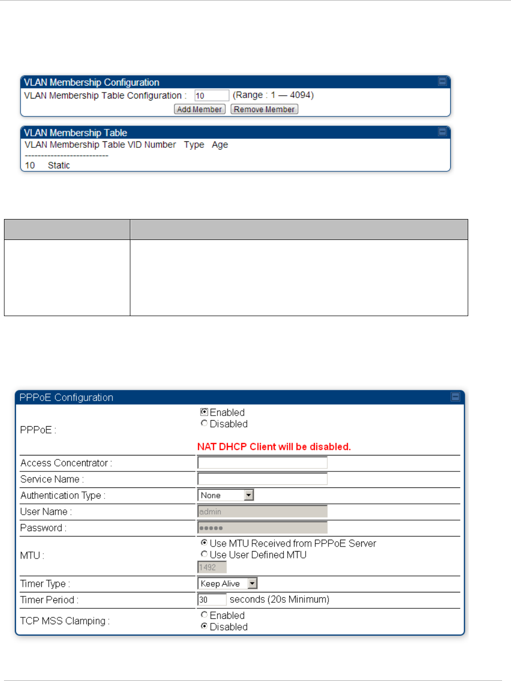
Task 2: Configuring IP and Ethernet interfaces PMP 450i and PTP 450i Configuration and User
Guide
VLAN Membership tab of the SM
Figure 18 VLAN Membership tab of the SM
In the VLAN Membership tab, you may set the following parameter.
Table 18 SM VLAN Membership attributes
Attribute Meaning
VLAN Membership
Table Configuration
For each VLAN in which you want the AP to be a member, enter
the VLAN ID and then click the Add Member button. Similarly,
for any VLAN in which you want the AP to no longer be a
member, enter the VLAN ID and then click the Remove
Member button.
PPPoE tab of the SM
Figure 19 PPPoE tab of the SM
pmp-0957 (April 2015) 51

PMP 450i and PTP 450i Configuration and User
Task 2: Configuring IP and Ethernet interfaces
Point-to-Point Protocol over Ethernet (PPPoE) is a protocol that encapsulates PPP frames
inside Ethernet frames (at Ethernet speeds). Benefits to the network operator may include
• Access control
• Service monitoring
• Generation of statistics about activities of the customer
• Re-use of infrastructure and operational practices by operators who already use PPP for
other networks
PPPoE options are configurable for the SM only, and the AP indicates whether or not
PPPoE is enabled for a specific subscriber.
When PPPoE is enabled, once the RF session comes up between the SM and the AP, the SM
will immediately attempt to connect to the PPPoE Server. You can monitor the status of this
by viewing the PPPoE Session Log in the Logs section (Administrator only). Every time the
RF session comes up, the SM will check the status of the link and if it is down, the SM will
attempt to redial the link if necessary depending on the Timer Type. Also, on the
Configuration page, the user may ‘Connect’ or ‘Disconnect’ the session manually. This can
be used to override the session to force a manual disconnect and/or reconnect if there is a
problem with the session.
In order to enable PPPoE, NAT MUST be enabled on the SM and Translation Bridging
MUST be disabled on the AP. These items is strictly enforced for you when you are trying
to enable PPPoE. A message will indicate any prerequisites not being met. Also, the NAT
Public IP DHCP client cannot be enabled, because the NAT Public IP is received through
the IPCP process of the PPPoE discovery stages.
The pre-requisites are:
• NAT MUST be enabled on the SM
o NAT DHCP Client is disabled automatically. The NAT public IP is
received from the PPPoE Server.
o NAT Public Network Interface Configuration will not be used and
must be left to defaults. Also NAT Public IP DHCP is disabled if it is
enabled.
• Translation Bridging MUST be DISABLED on the AP
o This will only be determined if the SM is in session since the SM
won’t know the AP configuration otherwise. If the SM is not in
session, PPPoE can be enabled but if the SM goes into session to a
Translation Bridge-enabled AP, then PPPoE will not be enabled.
The following PPPoE configuration parameters are available:
Table 19 SM PPPoE attributes
Attribute Meaning
Access
Concentrator
An optional entry to set a specific access concentrator to
connect to for the PPPoE session. If this is blank, the SM will
accept the first access concentrator which matches the
service name (if specified). This is limited to 32 characters.
52 pmp-0957 (April 2015)

Task 2: Configuring IP and Ethernet interfaces PMP 450i and PTP 450i Configuration and User
Guide
Attribute Meaning
Service Name An optional entry to set a specific service name to connect to
for the PPPoE session. If this is left blank the SM will accept
the first service option that comes back from the access
concentrator specified above, if any. This is limited to 32
characters.
Authentication
Type
None means that no PPPoE authentication is implemented
CHAP/PAP means that CHAP authentication is attempted
first, then PAP authentication. The same password is used for
both types.
User Name This is the CHAP/PAP user name that is used if CHAP/PAP
authentication is selected. If None is selected for
authentication then this field is unused. This is limited to 32
characters.
Password This is the CHAP/PAP password that is used if PAP
authentication is selected. If None is selected for
authentication then this field is unused. This is limited to 32
characters.
MTU
Use MTU Received from PPPoE Server causes the SM to
use the MRU of the PPPoE server received in LCP as the MTU
for the PPPoE link.
Use User Defined MTU allows the operator to specify an
MTU value to use to override any MTU that may be
determined in the LCP phase of PPPoE session setup. If this is
selected, the user is able to enter an MTU value up to 1492.
However, if the MTU determined in LCP negotiations is less
than this user-specified value, the SM will use the smaller
value as its MTU for the PPPoE link.
pmp-0957 (April 2015) 53

PMP 450i and PTP 450i Configuration and User
Task 2: Configuring IP and Ethernet interfaces
Attribute Meaning
Timer Type
Keep Alive is the default timer type. This timer will enable a
keepalive that will check the status of the link periodically.
The user can set a keepalive period. If no data is seen from
the PPPoE server for that period, the link is taken down and a
reconnection attempt is started. For marginal links, the keep
alive timer can be useful so that the session will stay alive
over periodic dropouts. The keepalive timer must be set such
that the session can outlast any session drop. Some PPPoE
servers will have a session check timer of their own so that
the timeouts of the server and the SM are in sync, to ensure
one side does not drop the session prematurely.
Idle Timeout enables an idle timer that checks the usage of
the link from the customer side. If there is no data seen from
the customer for the idle timeout period, the PPPoE session is
dropped. Once data starts flowing from the customer again,
the session is started up again. This timer is useful for users
who may not be using the connection frequently. If the
session is idle for long periods of time, this timer will allow the
resources used by the session to be returned to the server.
Once the connection is used again by the customer, the link is
reestablished automatically.
Timer Period The length in seconds of the PPPoE keepalive timer.
TCP MSS
Clamping
If this is enabled, then the SM will alter TCP SYN and SYN-
ACK packets by changing the Maximum Segment Size to be
compatible with the current MTU of the PPPoE link. This way,
the user does not have to worry about MTU on the client side
for TCP packets. The MSS is set to the current MTU – 40 (20
bytes for IP headers and 20 bytes for TCP headers). This will
cause the application on the client side to not send any TCP
packets larger than the MTU. If the network is exhibiting
large packet loss, try enabling this option. This may not be an
option on the PPPoE server itself. The SM will NOT
reassemble IP fragments, so if the MTUs are incorrect on the
end stations, then MSS clamping will solve the problem for
TCP connections.
54 pmp-0957 (April 2015)
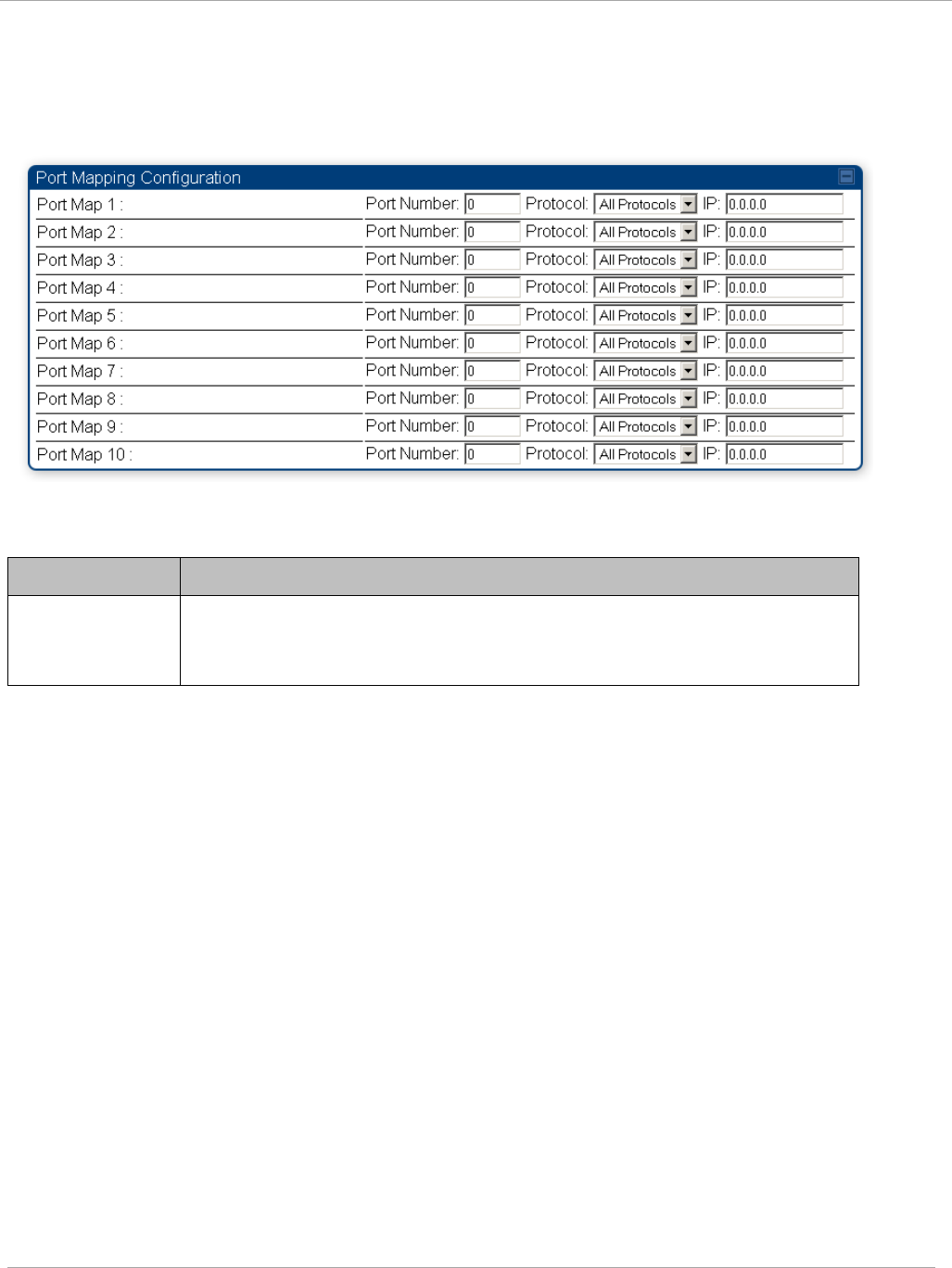
Task 2: Configuring IP and Ethernet interfaces PMP 450i and PTP 450i Configuration and User
Guide
NAT Port Mapping tab of the SM
An example of the NAT Port Mapping tab in a SM is displayed in below.
Figure 20 NAT Port Mapping tab of the SM
In the NAT Port Mapping tab of the SM, you may set the following parameters.
Table 20 SM NAT Port Mapping attributes
Attribute Meaning
Port Map
1 to
10
Separate parameters allow you to distinguish NAT ports from each
other by assigning a unique combination of port number, protocol for
traffic through the port, and IP address for access to the port
pmp-0957 (April 2015) 55
PMP 450i and PTP 450i Configuration and User
Task 3: Upgrading the software version and
using CNUT
Task 3: Upgrading the software version and using
CNUT
This task consists of the following procedures:
• Checking the installed software version on page 56
• Upgrading to a new software version on page 56
If the link is operational, ensure that the remote end of the link is upgraded first
using the wireless connection, and then the local end can be upgraded. Otherwise,
the remote end may not be accessible.
Always refer to the software release notes before upgrading system software. The
release notes are available at:
https://support.cambiumnetworks.com/files/PMP450i
Checking the installed software version
To check the installed software version, follow these instructions:
Procedure 5 Checking the installed software version
1 Click on General tab under Home menu.
2 Note the installed Software Version (under
Device Information
):
3 Go to the support website (see Contacting Cambium Networks on page xvi) and
find Point-to-Multipoint software updates. Check that the latest PMP 450i
software version is the same as the installed Software Version.
4 To upgrade software to the latest version, see Upgrading to a new software
version on page 56.
Upgrading to a new software version
PMP 450i modules are upgraded using the Canopy Network Updater Tool. The
Canopy Network Updater Tool (CNUT) manages and automates the software and
firmware upgrade process for a Canopy radio, CMMmicro, or CMM4 (but not its 14-
port switch) across the network. This eliminates the need for an administrator to
visit each radio in the network (or each AP while using the Autoupdate feature) to
upgrade the modules.
56 pmp-0957 (April 2015)

Task 3: Upgrading the software version and usin
PMP 450i and PTP 450i Configuration and User
Guide
Please ensure that you have the most up-to-date version of CNUT by browsing to the
Customer Support Web Page located:
http://www.cambiumnetworks.com/support/management-tools/cnut
This section includes an example of updating a single unit before deployment.
System-wide upgrading procedures may be found in the
CNUT Online Help
manual,
which can be found on the Cambium support website (see Contacting Cambium
Networks on page xvi).
CNUT functions
The Canopy Network Updater tool has the following functions:
• Automatically discovers all network elements
• Executes a UDP command that initiates and terminates the Auto-update mode within
APs. This command is both secure and convenient:
o For security, the AP accepts this command from only the IP address
that you specify in the Configuration page of the AP.
o For convenience, Network Updater automatically sets this
Configuration parameter in the APs to the IP address of the
Network Updater server when the server performs any of the
update commands.
• CNUT supports HTTP and HTTPs
• Allows you to choose the following among updating:
o Your entire network.
o Only elements that you select.
o Only network branches that you select.
• Provides a Script Engine that you can use with any script that:
o You define.
o Cambium supplies.
• Configurability of any of the following to be the file server for image files:
o The AP, for traditional file serving via UDP commands and
monitoring vai UDP messaging
o CNUT HTTP/HTTPS Server, for upgrading via SNMP commands
and monitoring via SNMP messaging. This also supports an option
to either set the image order specifically for this file server or to
allow the AP to determine the order.
o Local TFTP Server, for traditional file serving via UDP commands
and monitoring via UDP messaging. This supports setting the
number of simultaneous image transfers per AP
• The capability to launch a test of connectivity and operational status of the local HTTP,
HTTPS and TFTP file servers
• An interface that supports efficient specification of the proper IP address for the local
file server(s) where Network Updater resides on a multi-homed computer
pmp-0957 (April 2015) 57

PMP 450i and PTP 450i Configuration and User
Task 3: Upgrading the software version and
using CNUT
• An md5 checksum calculator utility for identifying corruption of downloaded image files
before Network Updater is set to apply them.
Network element groups
With the Canopy Network Updater Tool, you can identify element groups composed
of network elements that you select. Identifying these element groups does the
following:
• Organizes the display of elements (for example, by region or by AP cluster).
• Allows you to:
o Perform an operation on all elements in the group simultaneously.
o Set group-level defaults for ftp password access and SNMP
Community String (defaults that can be overridden in an individual
element when necessary).
Network layers
A typical network contains multiple layers of elements, with each layer farther from
the Point of Presence. For example, SMs are behind an AP and thus, in this context,
at a lower layer than the AP. Correctly portraying these layers in Network Updater
is essential so that Network Updater can perform radio and AP cluster upgrades in
an appropriate order.
Script engine
Script Engine is the capability in Network Updater that executes any user-defined
script against any network element or element group. This capability is useful for
network management, especially for scripts that you repetitively execute across
your network.
The Autodiscovery capability in Network Updater finds all of your network
elements. This comprehensive discovery:
• Ensures that, when you intend to execute a script against
all
elements, the script is
indeed executed against
all
elements.
• Maintains master lists of elements (element groups) against which you selectively
execute scripts.
The following scripts are included with CNUT:
• Gather Customer Support Information
• Set Access Point Authentication Mode
• Set Autoupdate Address on APs
• Set SNMP Accessibility
• Reset Unit
58 pmp-0957 (April 2015)

Task 3: Upgrading the software version and usin
PMP 450i and PTP 450i Configuration and User
Guide
Software dependencies for CNUT
CNUT functionality requires
• one of the following operating systems
o Windows® 2000
o Windows Server 2003
o Windows 7 and Windows 8
o Windows XP or XP Professional
o Red Hat Enterprise Linux (32-bit) Version 4 or 5
• Java™ Runtime Version 2.0 or later (installed by the CNUT installation tool)
CNUT download
CNUT can be downloaded together with each system release that supports CNUT.
Software for these system releases is available from
http://www.cambiumnetworks.com/support/management-tools/cnut/, as either:
• A .zip file for use without the CNUT application.
• A .pkg file that the CNUT application can open.
Upgrading a module prior to deployment
To upgrade to a new software version, follow this:
Procedure 6 Upgrading a module prior to deployment
1 Go to the support website (see Contacting Cambium Networks on page xvi) and
find Point-to-Multipoint software updates. Download and save the required
software image.
2 Start CNUT
3 If you don’t start up with a blank new network file in CNUT, then open a new
network file with the New Network Archive operation (located at File => New
Network).
4 Enter a new network element to the empty network tree using the Add Elements
to Network Root operation (located at Edit => Add Elements to Network
Root).
5 In the Add Elements dialogue, select a type of Access Point or Subscriber
Module and enter the IP address of 169.254.1.1.
6 Make sure that the proper Installation Package is active with the Package
Manager dialogue (located at Update => Manage Packages).
7 To verify connectivity with the radio, perform a Refresh, Discover Entire
Network operation (located at View => Refresh/Discover Entire Network).
You must see the details columns for the new element filled in with ESN and
software version information.
pmp-0957 (April 2015) 59

PMP 450i and PTP 450i Configuration and User
Task 3: Upgrading the software version and
using CNUT
8 Initiate the upgrade of the radio using Update Entire Network Root operation
(located at Update => Update Entire Network Root). When this operation
finishes, the radio is done being upgraded.
60 pmp-0957 (April 2015)
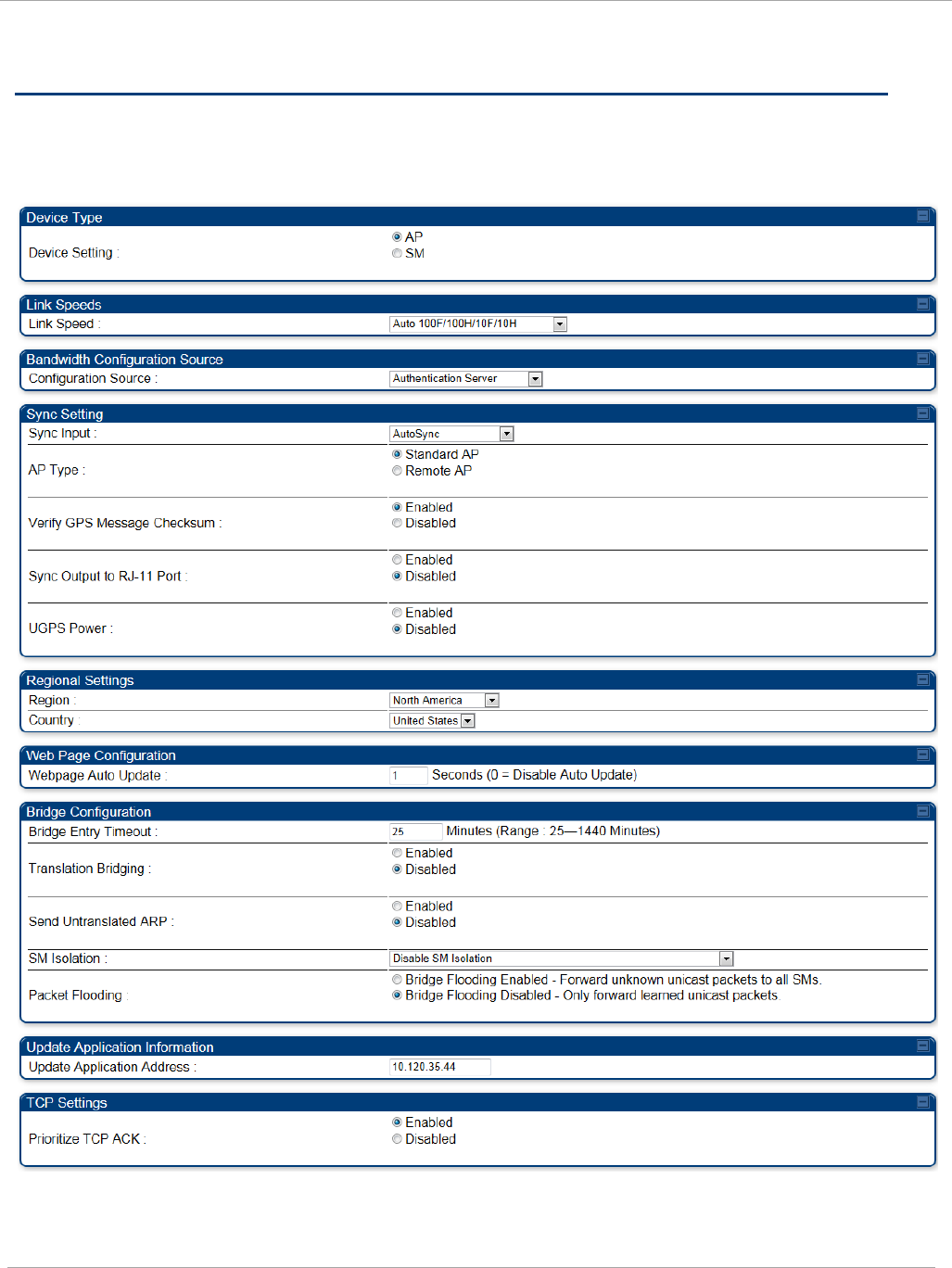
Task 4: Configuring General and Unit settings PMP 450i and PTP 450i Configuration and User
Guide
Task 4: Configuring General and Unit settings
General tab of the AP’s Configuration section
Figure 21 General tab
pmp-0957 (April 2015) 61
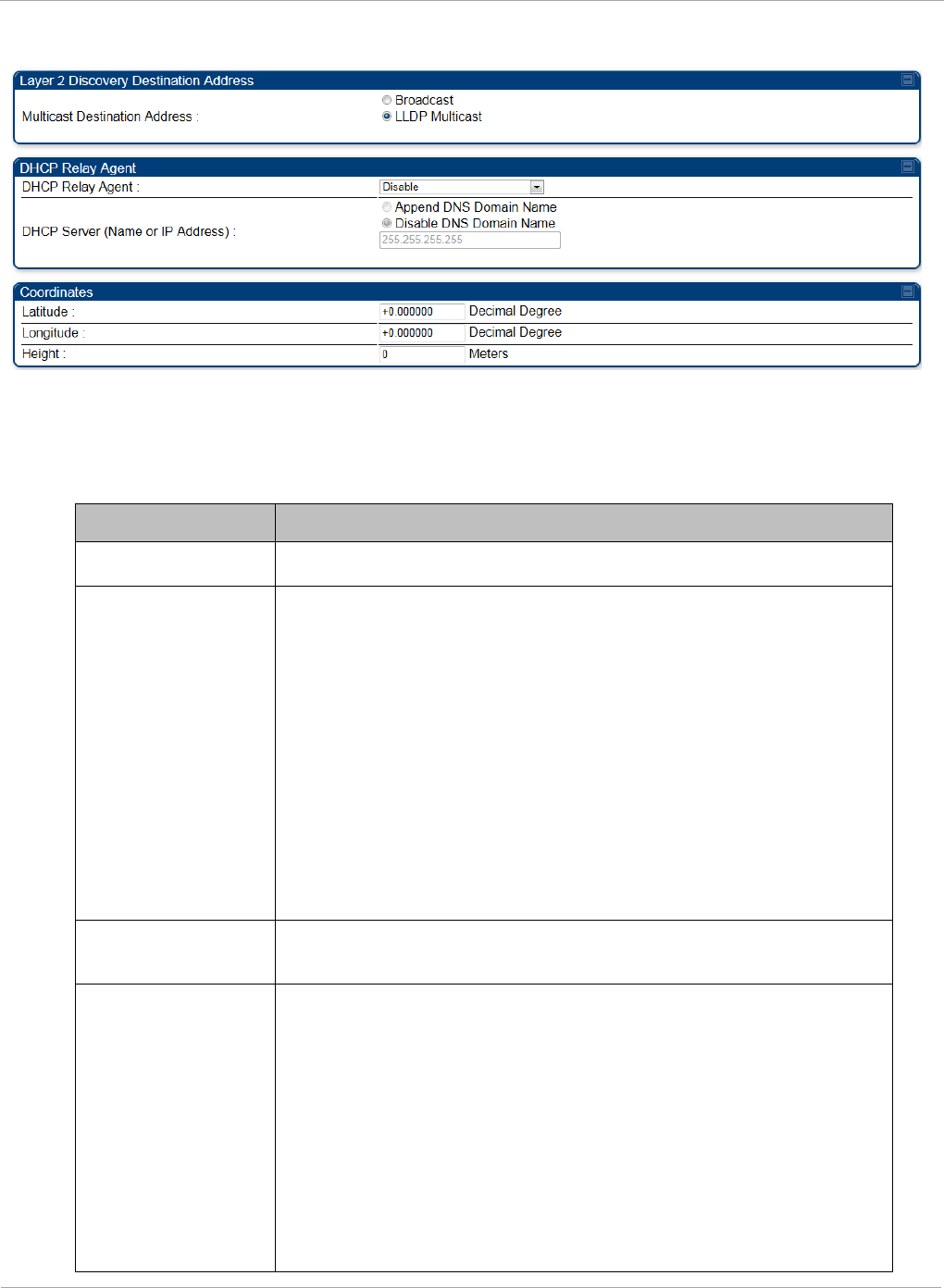
PMP 450i and PTP 450i Configuration and User
Task 4: Configuring General and Unit settings
Continue…
The General tab of the AP’s Configuration section contains many of the
configurable parameters that define how the AP and the SMs in the sector operate.
Table 21 AP General tab attributes
Attribute Meaning
Device Setting Allows the Spectrum Analyzer to be run directly from AP now.
Link Speeds
From the drop-down list of options, select the type of link
speed for the Ethernet connection. The default for this
parameter is that all speeds are selected: Auto
100F/100H/10F/10H. In this setting, the two ends of the link
automatically negotiate with each other whether the speed
that they will use is 10 Mbps or 100 Mbps and whether the
Ethernet traffic is full duplex or half duplex. However,137
Ethernet links work best when either:
• both ends are set to the same forced selection
• both ends are set to auto-negotiate and both have
capability in least one common speed and traffic type
combination.
Configuration
Source
See Setting the Configuration Source on page 159.
Sync Input AutoSync: The AP automatically receives sync from one of the
following sources:
• GPS Sync over Timing Port (UGPS, co-located AP GPS sync
output, or “Remote AP” feed from a registered SM’s GPS
sync output)
• GPS Sync over Power Port (CMM)
• On-board GPS (internal GPS)
Upon AP power on, the AP does not transmit until a valid
synchronization pulse is received from one of the sources
above. When there are synchronization sources on both the
62 pmp-0957 (April 2015)

Task 4: Configuring General and Unit settings PMP 450i and PTP 450i Configuration and User
Guide
Attribute Meaning
timing port and the power port, the power port GPS source is
chosen first.
If there is a loss of GPS synchronization pulse, within two
seconds the AP automatically attempts to source GPS signaling
from another source. On-board GPS (internal GPS) is the last
source checked for GPS signaling if there is no receipt of
signaling from the timing port or from the power port (the on-
board GPS module must not be used as the primary timing
source). If no valid GPS signal is received, the AP ceases
transmission and SM registration is lost until a valid GPS
signal is received again on the AP.
AutoSync + Free Run: This mode operates similarly to mode
“AutoSync”, but if a previously received synchronization signal
is lost and no GPS signaling alternative is achieved (from the
timing port, power port, or on-board GPS), the AP
automatically changes to synchronization mode “Generate
Sync”. While SM registration ins maintained, in this mode
there is no synchronization of APs that can “hear” each other;
the AP will only generate a sync signal for the local AP and its
associated SMs. Once a valid GPS signal is obtained again, the
AP automatically switches to receiving synchronization via the
GPS source and SM registration is maintained.
In mode AutoSync + Free Run, if a GPS signal is never
achieved initially, the system will not switch to “Free Run”
mode, and SMs will not register to the AP. A valid GPS
signal must be present initially for the AP to switch into
“Free Run” mode (and to begin self-generating a
synchronization pulse).
Also, When an AP is operating in “Free Run” mode, over a
short time it will no longer be synchronized with co-located
or nearby APs (within radio range). Due to this lack of
transmit and receive synchronization across APs or across
systems, performance while in “Free Run” mode may be
degraded until the APs operating in “Free Run” mode
regain a external GPS synchronization source. Careful
attention is required to ensure that all systems are
properly receiving an external GPS synchronization pulse,
and please consider “Free Run” mode as an emergency
option.
Generate Sync (factory default): This option may be used
when the AP is not receiving GPS synchronization pulses from
either a CMM or UGPS module, and there are no other APs
active within the link range. Using this option will not
pmp-0957 (April 2015) 63

PMP 450i and PTP 450i Configuration and User
Task 4: Configuring General and Unit settings
Attribute Meaning
synchronize transmission of APs that can “hear” each other; it
will only generate a sync signal for the local AP and its
associated SMs.
AP Type Standard AP: The Autosync mechanism will source GPS
synchronization from the AP’s RJ-11 port, the AP’s power port,
or from the device on-board GPS module.
Remote AP: The Autosync mechanism will source GPS
synchronization from the AP’s RJ-11 port or from the device
on-board GPS module.
Verify GPS
Message
Checksum
This ensures that the messages coming from the GPS are valid
by parsing them with a MD4 checksum.
Sync Output to RJ-
11 Port
This is used when the user wants to use the PMP450i AP to
provide Sync to another radio or device.
UGPS Port This allows the PMP450i AP to power up the UGPS via its Sync
port.
Region From the drop-down list, select the region in which the radio is
operating.
Country
From the drop-down list, select the country in which the radio
is operating.
Unlike selections in other parameters, your Country selection
requires a Save Changes and a Reboot cycle before it will
force the context-sensitive GUI to display related options (for
example, Alternate Frequency Carrier
1 and 2
in the
Configuration => Radio tab).
PMP 450i equipment shipped to the United States is locked to
a Region Code setting of “United States”. Units shipped to
regions other than the United States must be configured with
the corresponding Region Code to comply with local regulatory
requirements.
Country Code settings affect the radios in the following ways:
• Maximum transmit power limiting (based on radio
transmitter power plus configured antenna gain)
• DFS operation is enabled based on the configured region
code, if applicable
For more information on how transmit power limiting and DFS
is implemented for each country, see the
PMP 450i Planning
Guide
.
Webpage Auto
Update
Enter the frequency (in seconds) for the web browser to
automatically refresh the web-based interface. The default
64 pmp-0957 (April 2015)

Task 4: Configuring General and Unit settings PMP 450i and PTP 450i Configuration and User
Guide
Attribute Meaning
setting is 0. The 0 setting causes the web-based interface to
never be automatically refreshed.
Bridge Entry
Timeout
Specify the appropriate bridge timeout for correct network
operation with the existing network infrastructure. The Bridge
Entry Timeout must be a longer period than the ARP (Address
Resolution Protocol) cache timeout of the router that feeds the
network.
An inappropriately low Bridge Entry Timeout setting may
lead to temporary loss of communication with some end
users.
Translation
Bridging
Optionally, you can configure the AP to change the source
MAC address in every packet it receives from its SMs to the
MAC address of the SM that bridged the packet, before
forwarding the packet toward the public network. If you do,
then:
• Not more than 10 IP devices at any time are valid to send
data to the AP from behind the SM.
• AP populates the Translation Table tab of its Statistics web
page, displaying the MAC address and IP address of all the
valid connected devices.
• Each entry in the Translation Table is associated with the
number of minutes that have elapsed since the last packet
transfer between the connected device and the SM.
• If 10 are connected and another attempts to connect:
o If no Translation Table entry is older than 255
minutes, the attempt is ignored.
o If an entry is older than 255 minutes, the oldest
entry is removed and the attempt is successful.
• the Send Untranslated ARP parameter in the General tab of
the Configuration page can be:
o Disabled, so that the AP overwrites the MAC
address in Address Resolution Protocol (ARP)
packets before forwarding them.
o Enabled, so that the AP forwards ARP packets
regardless of whether it has overwritten the MAC
address.
When this feature is disabled, the setting of the
Send Untranslated ARP parameter has no effect, because all
packets are forwarded untranslated (with the source MAC
address intact).
Send Untranslated If the Translation Bridging parameter is set to Enabled,
pmp-0957 (April 2015) 65

PMP 450i and PTP 450i Configuration and User
Task 4: Configuring General and Unit settings
Attribute Meaning
ARP
then the Send Untranslated ARP parameter can be:
Disabled - so that the AP will overwrite the MAC address in
Address Resolution Protocol (ARP) packets before forwarding
them.
Enabled - so that the AP will forward ARP packets regardless
of whether it has overwritten the MAC address.
If the Translation Bridging parameter is set to Disabled,
then the Send Untranslated ARP parameter has no effect.
SM Isolation
Prevent or allow SM-to-SM communication by selecting from
the following drop-down menu items:
Disable SM Isolation (the default selection). This allows full
communication between SMs.
Block SM Packets from being forwarded. This prevents
both multicast/broadcast and unicast SM-to-SM
communication.
Block and Forward SM Packets to Backbone. This not only
prevents multicast/broadcast and unicast SM-to-SM
communication but also sends the packets, which otherwise
are handled SM to SM, through the Ethernet port of the AP.
Packet Flooding Enabled: All unknown Unicast packets (no entry in the AP’s
bridge table) received via the AP’s Ethernet LAN interface are
forwarded to registered SMs. If the target device is situated
beneath a particular SM, when the device responds the SM
and AP will learn and add the device to their bridge tables so
that subsequent packets to that device is bridged to the proper
SM.
Disabled: All unknown Unicast packets (no entry in the AP’s
bridge table) received via the AP’s Ethernet LAN interface are
discarded at the AP.
Update
Application
Address
Enter the address of the server to access for software updates
on this AP and registered SMs.
Prioritize TCP ACK To reduce the likelihood of TCP acknowledgement packets
being dropped, set this parameter to Enabled. This can
improve throughput that the end user perceives during
transient periods of congestion on the link that is carrying
acknowledgements. This parameter, when enabled, can be
particularly useful when running bi-direction FTP sessions
over the link. If a link is primarily used for video surveillance,
it is recommended to set this parameter to Disable.
Multicast
Destination
Using Link Layer Discovery Protocol (LLDP), a module
exchanges multicast addresses with the device to which it is
66 pmp-0957 (April 2015)

Task 4: Configuring General and Unit settings PMP 450i and PTP 450i Configuration and User
Guide
Attribute Meaning
Address
wired on the Ethernet interface. Although some switches
(CMMmicro, for example) do not pass LLDP addresses upward
in the network, a radio can pass it as the value of the
Multicast Destination Address parameter value in the
connected device that has it populated.
DHCP Relay Agent
The AP may act as a DHCP relay for SMs and CPEs underneath
it. The AP will make use of the DHCP Option 82 (DHCP Relay
Agent Information) from RFC 3046 when performing relay
functions. The AP offers two types of DHCP relay
functionality:
Full Relay Information. Configuring the DHCP Full Relay
Operation will take broadcast DHCP packets and send them to
a Unicast server in unicast mode. This way the DHCP requests
and replies can be routed like any other UDP packet.
Only Insert Option 82. This option leaves the DHCP request
on its broadcast domain as opposed to DHCP Full Relay
Operation which will turn it into a unicast packet.
In order to accommodate setting up pools or classes for
different VLANs, the Option 82 field will include information to
tell the server what VLAN the client is on.
DHCP Server
(Name or IP
Address)
The DHCP relay server may be either a DNS name or a static
IP address in dotted decimal notation. Additionally the
management DNS domain name may be toggled such that the
name of the DHCP relay server only needs to be specified and
the DNS domain name is automatically appended to that name.
The default DHCP relay server addresses is 255.255.255.255
with the appending of the DNS domain name disabled.
Latitude Physical radio location data may be configured via the
Latitude, Longitude and Height fields.
Latitude and Longitude is measured in
Decimal Degree
while
the Height is calculated in
Meters.
Longitude
Height
pmp-0957 (April 2015) 67
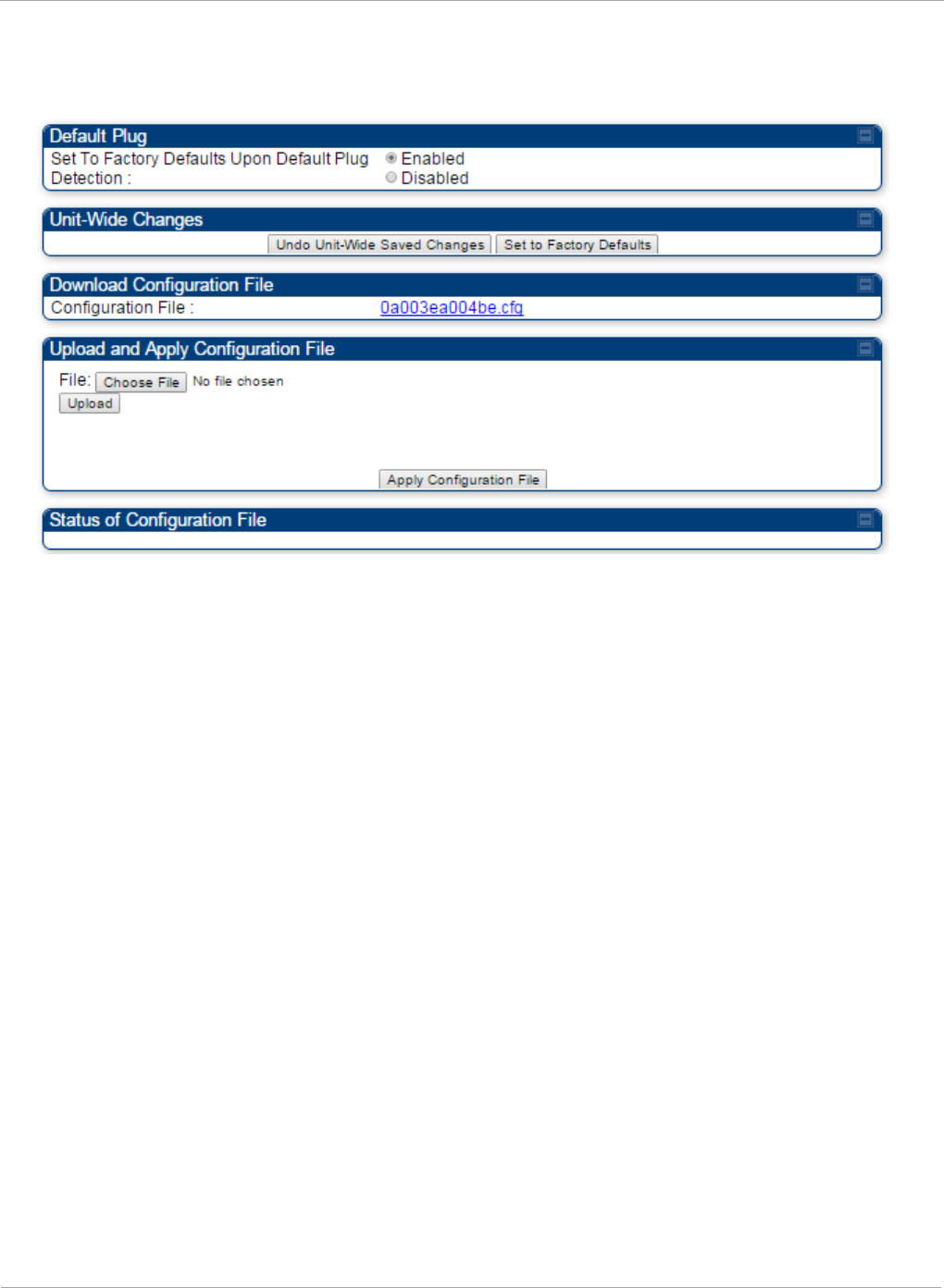
PMP 450i and PTP 450i Configuration and User
Task 4: Configuring General and Unit settings
Unit Settings tab of the AP
Figure 22 Unit Settings tab of the AP
The Unit Settings tab of the AP contains following options:
• Default Plug
• Unit-Wide Changes
• Download Configuration File
• Upload and Apply Configuration File
The Default Plug option controls how the AP must react when it detects a connected
override plug.
The PMP also supports import and export of configuration from the AP or SM as a text file.
The configuration file is in JSON format. The logged in user must be an ADMINISTRATOR
in order to export or import the configuration file.
The exported configuration file contains the complete configuration including all the
default values. To keep a backup of the current configuration, the file can be saved as-is
and imported later. The Import and Export procedure of configuration file is described in
Import and Export of config file on page 182.
68 pmp-0957 (April 2015)

Task 4: Configuring General and Unit settings PMP 450i and PTP 450i Configuration and User
Guide
Table 22 AP Unit Settings attributes
Attribute Meaning
Set to Factory
Defaults Upon
Default Plug
Detection
If Enabled is checked, then an override/default plug
functions as a default plug. When the module is rebooted with
the plug inserted, it can be accessed at the IP address
169.254.1.1 and no password, and all parameter values are
reset to defaults. A subscriber, technician, or other person
who gains physical access to the module and uses an
override/default plug
cannot
see or learn the settings that
were previously configured in it. When the module is later
rebooted with no plug inserted, the module uses the new
values for any parameters that were changed and the default
values for any that were not.
If Disabled is checked, then an override (default) plug
functions as an override plug. When the module is rebooted
with the plug inserted, it can be accessed at the IP address
169.254.1.1 and no password, and all previously configured
parameter values remain and are displayed. A subscriber,
technician, or other person who gains physical access to the
module and uses an override/default plug
can
see and learn
the settings. When the module is later rebooted with no plug
inserted, the module uses the new values for any parameters
that were changed and the previous values for any that were
not.
See Overriding Forgotten IP Addresses or Passwords on AP
on Page 83.
When Set to Factory Defaults Upon Default Plug
Detection is set to “Enable”, the radio does not select all of
the frequencies for Radio Frequency Scan Selection List. It
needs to be selected manually.
Undo Unit-Wide
Saved Changes
When you click this button, any changes that you made in any
tab but did not commit by a reboot of the module are undone.
Set to Factory
Defaults
When you click this button,
all configurable parameters on all
tabs
are reset to the factory settings.
Configuration File This allows to download the configuration file of the radio.
This configuration file contains the complete configuration
including all the default values. The configuration file is
highlighted as downloadable link and the naming convention
is “<mac address of AP>.cfg”.
pmp-0957 (April 2015) 69

PMP 450i and PTP 450i Configuration and User
Task 4: Configuring General and Unit settings
Attribute Meaning
Apply
Configuration File
This allows to import and apply configuration to the AP.
Chose File: Select the file to upload the configuration. The
configuration file is named as “<file name>.cfg”.
Upload: Import the configuration to the AP.
Apply Configuration File: Apply the imported file
configuration to the AP.
The configuration file can be either imported the full
configuration or a sparse configuration containing on the
items that need to be changed. If a sparse configuration file is
imported, only the items in the file will be imported. Other
configuration will remain unchanged. There could also be
used a special flag in the configuration file to tell the device
to apply the configuration starting from factory default.
Status of
Configuration file
This section shows the results of the upload.
70 pmp-0957 (April 2015)
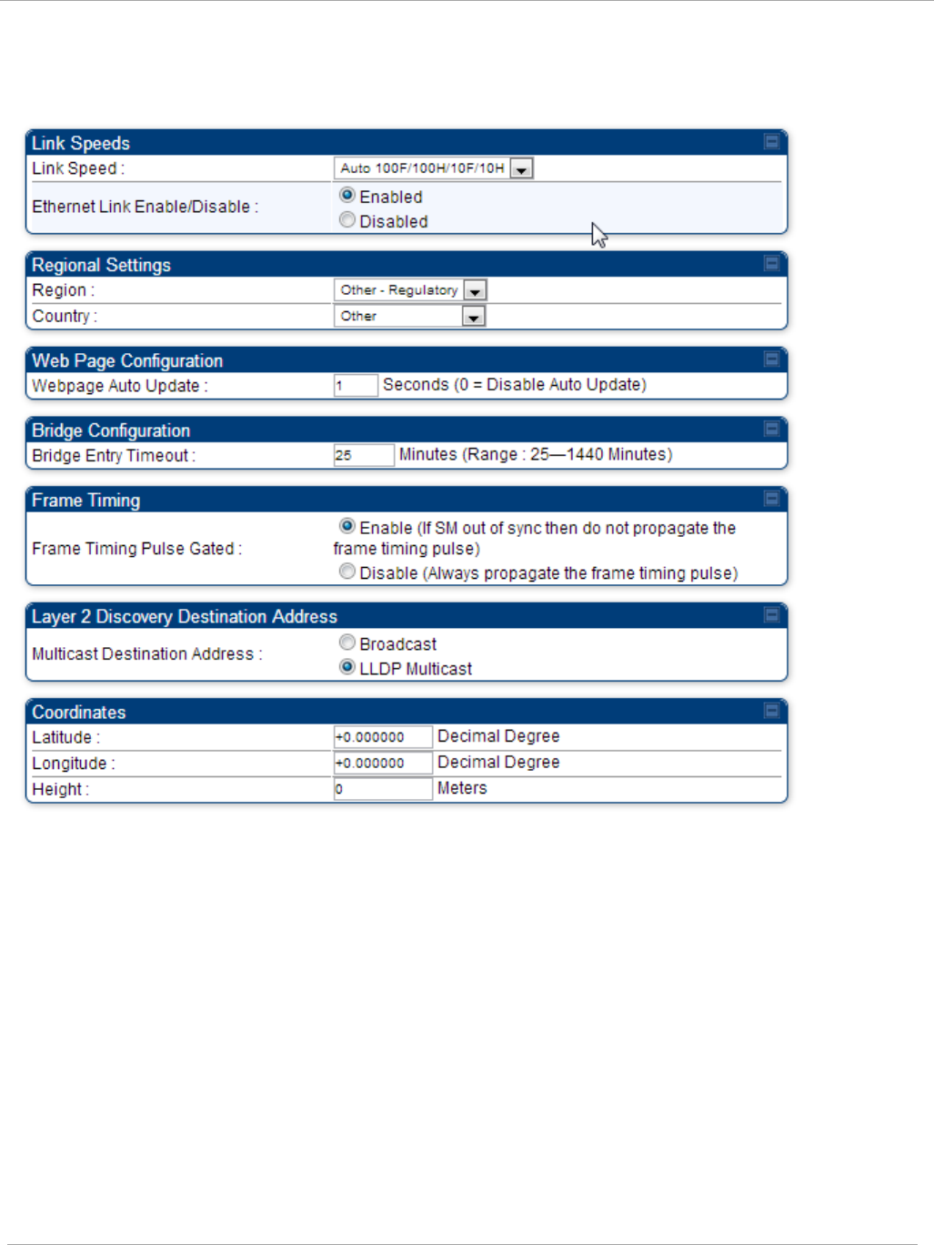
Task 4: Configuring General and Unit settings PMP 450i and PTP 450i Configuration and User
Guide
General tab of the SM
Figure 23 General tab of the SM
pmp-0957 (April 2015) 71

PMP 450i and PTP 450i Configuration and User
Task 4: Configuring General and Unit settings
In the General tab of the SM, you may set the following parameters.
Table 23 SM General Configuration attributes
Attribute Meaning
Link Speeds From the drop-down list of options, select the type of link speed
for the Ethernet connection. The default for this parameter is
that all speeds are selected. The recommended setting is a single
speed selection for all APs and SMs in the operator network.
Ethernet Link
Enable/Disable
Specify whether to enable or disable Ethernet/802.3 connectivity
on the wired port of the SM. This parameter has no effect on the
wireless link. When you select Enable, this feature allows traffic
on the Ethernet/802.3 port. This is the factory default state of the
port. When you select Disable, this feature prevents traffic on
the port. Typical cases of when you may want to select Disable
include:
The subscriber is delinquent with payment(s).
You suspect that the subscriber is sending or flooding undesired
broadcast packets into the network, such as when
a virus is present in the subscriber's computing device.
the subscriber's home router is improperly configured.
Region This parameter allows you to set the region in which the radio
will operate.
The SM radio automatically inherits the Region type of the
master. This behavior ignores the value of the Region parameter
in the SM, even when the value is None. Nevertheless, since
future system software releases may read the value in order to
configure some other region-sensitive feature(s), this parameter
must be always set to the value that corresponds to the local
region.
Country
This parameter allows you to set the country in which the radio
will operate.
The SM radio automatically inherits the Country Code type of the
master. This behavior ignores the value of the Country
parameter in the SM, even when the value is None.
Nevertheless, since future system software releases may read the
value in order to configure some other region-sensitive
feature(s), this parameter must be always set to the value that
corresponds to the local region.
PMP 450i equipment shipped to the United States is locked to a
Region Code setting of “United States”. Units shipped to regions
other than the United States must be configured with the
corresponding Region Code to comply with local regulatory
requirements.
72 pmp-0957 (April 2015)

Task 4: Configuring General and Unit settings PMP 450i and PTP 450i Configuration and User
Guide
Attribute Meaning
Webpage Auto
Update
Enter the frequency (in seconds) for the web browser to
automatically refresh the web-based interface. The default
setting is
0
. The 0 setting causes the web-based interface to
never be automatically refreshed.
Bridge Entry
Timeout
Specify the appropriate bridge timeout for correct network
operation with the existing network infrastructure. Timeout
occurs when the AP encounters no activity with the SM (whose
MAC address is the bridge entry) within the interval that this
parameter specifies. The Bridge Entry Timeout must be a longer
period than the ARP (Address Resolution Protocol) cache timeout
of the router that feeds the network.
This parameter governs the timeout interval, even if a router
in the system has a longer timeout interval. The default value
of this field is
25
(minutes).
An inappropriately low Bridge Entry Timeout setting may
lead to temporary loss of communication with some end
users.
Frame Timing
Pulse Gated
If this SM extends the sync pulse to a BH master or an AP, select
either
Enable—If this SM loses sync from the AP, then
do not
propagate a sync pulse to the BH timing master or other AP. This
setting prevents interference in the event that the SM loses sync.
Disable—If this SM loses sync from the AP, then propagate the
sync pulse to the BH timing master or other AP.
Multicast
Destination
Address
Using Link Layer Discovery Protocol (LLDP), a module exchanges
multicast addresses with the device to which it is wired on the
Ethernet interface. Although some switches (CMMmicro, for
example) do not pass LLDP addresses upward in the network, a
radio can pass it as the value of the Multicast Destination
Address parameter value in the connected device that has it
populated.
Coordinates Physical radio location data may be configured via the Latitude,
Longitude and Height fields.
pmp-0957 (April 2015) 73
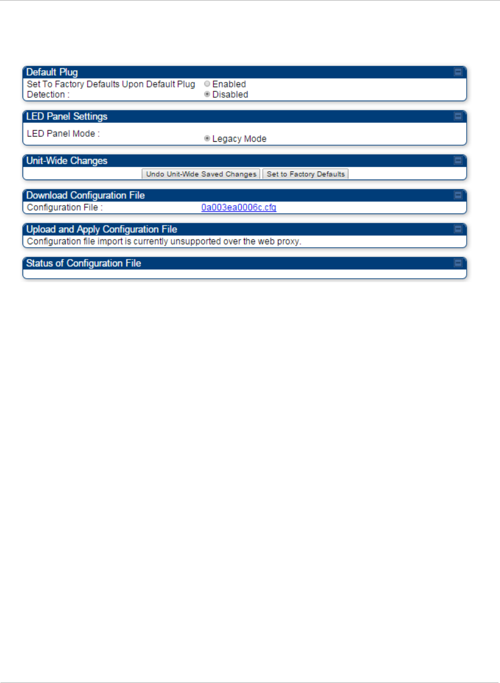
PMP 450i and PTP 450i Configuration and User
Task 4: Configuring General and Unit settings
Unit Settings tab of the SM
Figure 24 Unit Settings tab of the SM
The Unit Settings tab of the SM contains following options:
• Default Plug
• LED Panel Settings
• Download Configuration File
Default Plug is an option for how the SM must react when it detects a connected override
plug.
The exiting configuration of SM can be exported as a text file via Download
Configuration File section. The procedure for import configuration file is described in
Import and Export of config file on page 182.
74 pmp-0957 (April 2015)

Task 4: Configuring General and Unit settings PMP 450i and PTP 450i Configuration and User
Guide
Table 24 SM Unit Settings attributes
Attribute Meaning
Set to Factory
Defaults Upon
Default Plug
Detection
If Enabled is checked, then an override/default plug functions as a
default plug. When the module is rebooted with the plug inserted, it
can be accessed at the IP address 169.254.1.1 and no password, and
all parameter values are reset to defaults. A subscriber, technician, or
other person who gains physical access to the module and uses an
override/default plug
cannot
see or learn the settings that were
previously configured in it. When the module is later rebooted with no
plug inserted, the module uses the new values for any parameters
that were changed and the default values for any that were not.
If Disabled is checked, then an override/default plug functions as an
override plug. When the module is rebooted with the plug inserted, it
can be accessed at the IP address 169.254.1.1 and no password, and
all previously configured parameter values remain and are displayed.
A subscriber, technician, or other person who gains physical access
to the module and uses an override/default plug
can
see and learn the
settings. When the module is later rebooted with no plug inserted, the
module uses the new values for any parameters that were changed
and the previous values for any that were not.
See Overriding Forgotten IP Addresses or Passwords on AP on Page
83.
LED Panel Mode Legacy Mode configures the radio to operate with standard LED
behavior (see section “SM Interfaces” in the
PMP 450i Planning
Guide
or in the
PMP 450i Installation Guide
)
Undo Unit-Wide
Saved Changes
When you click this button, any changes that you made in any tab but
did not commit by a reboot of the module are undone.
Set to Factory
Defaults
When you click this button,
all configurable parameters on all tabs
are reset to the factory settings.
This can be reverted by selecting "Undo Unit-Wide Saved Changes",
before
rebooting the radio.
Configuration File This allows to download the configuration file of the radio. This
configuration file contains the complete configuration including all
the default values. The configuration file is highlighted as
downloadable link and the naming convention is “<mac address of
AP>.cfg”.
Status of
Configuration file
This section shows the results of the Configuration file.
pmp-0957 (April 2015) 75
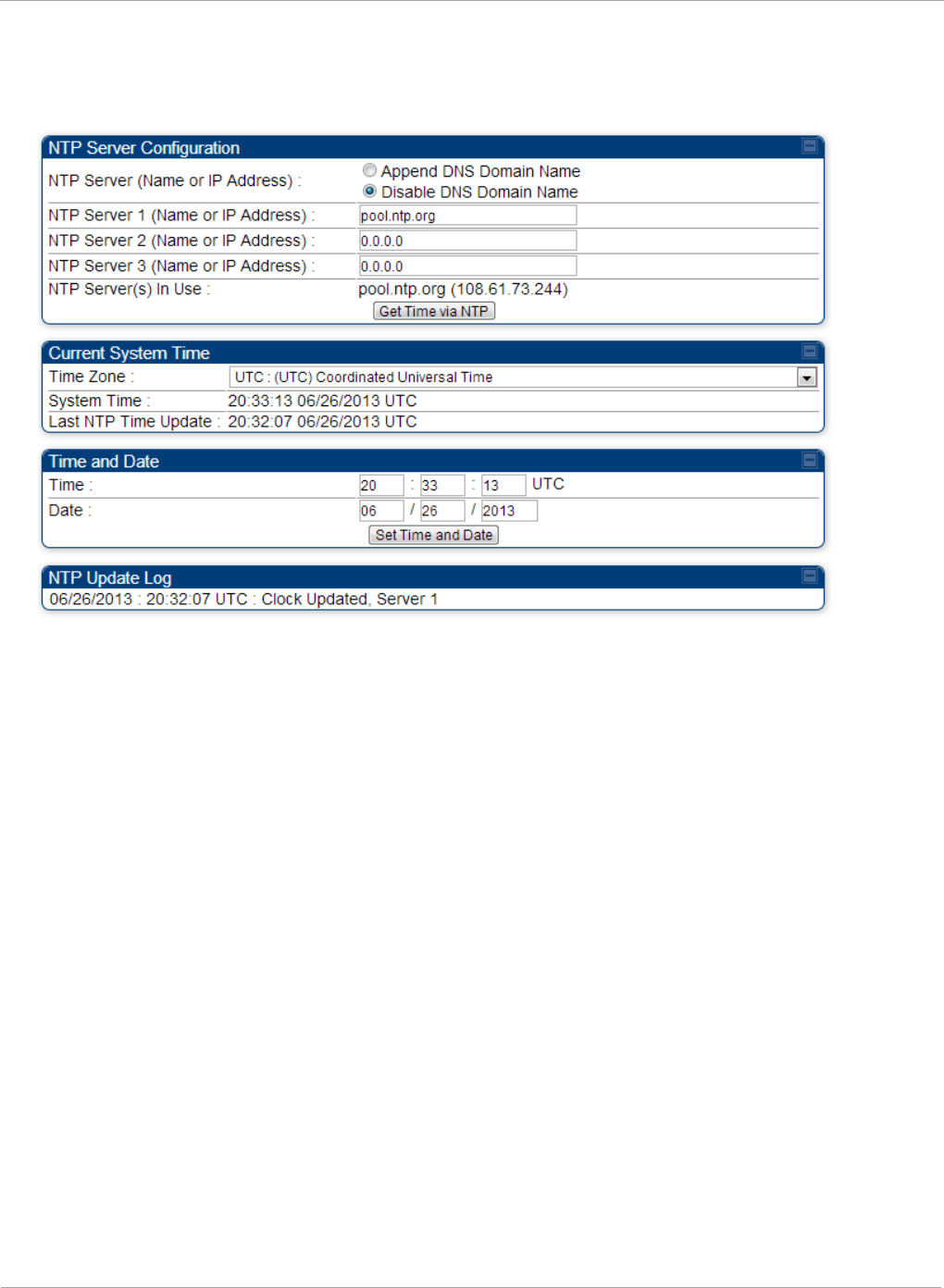
PMP 450i and PTP 450i Configuration and User
Task 4: Configuring General and Unit settings
Time tab of the AP
Figure 25 Time tab of the AP
76 pmp-0957 (April 2015)

Task 4: Configuring General and Unit settings PMP 450i and PTP 450i Configuration and User
Guide
You may set the time parameters as follows:
Table 25 AP Time attributes
Attribute Meaning
NTP Server (Name or
IP Address)
The management DNS domain name may be toggled such that
the name of the NTP server only needs to be specified and the
DNS domain name is automatically appended to that name.
NTP Server 1 (Name
or IP Address)
NTP Server 2 (Name
or IP Address)
NTP Server 3 (Name
or IP Address)
To have each log in the AP correlated to a meaningful time and
date, either a reliable network element must pass time and date
to the AP or you must set the time and date whenever a power
cycle of the AP has occurred. A network element passes time and
date in any of the following scenarios:
• A connected CMM2 or CMM4 passes time and date (GPS time
and date, if received).
• A connected CMMmicro passes the time and date (GPS time
and date, if received), but only if both the CMMmicro is
operating on CMMmicro Release 2.1 or later release. (These
releases include NTP server functionality.)
• A separate NTP server (including APs receiving NTP data) is
addressable from the AP.
If the AP needs to obtain time and date from a CMMmicro,
CMM4, or a separate NTP server, enter the IP address or DNS
name of the CMM or NTP server on this tab. To force the AP to
obtain time and date before the first (or next) 15-minute interval
query of the NTP server, click Get Time via NTP.
The polling of the NTP servers is done in a sequential fashion,
and the polling status of each server is displayed in the NTP
Update Log section of the Time Configuration page. An entry of
0.0.0.0 in any of the NTP Server fields indicates an unused server
configuration.
NTP Server(s) in Use Lists the IP addresses of servers used for NTP retrieval.
Time Zone The Time Zone option may be used to offset the received NTP
time to match the operator’s local time zone. When set on the AP,
the offset is set for the entire sector (SMs is notified of the
current Time Zone upon initial registration). If a Time Zone
change is applied, the SMs is notified of the change in a best
effort fashion, meaning some SMs may not pick up the change
until the next re-registration. Time Zone changes are noted in the
Event Log of the AP and SM.
System Time The current time used by the system.
Last NTP Time Update The last time that the system time was set via NTP.
Time This field may be used to manually set the system time of the
radio.
pmp-0957 (April 2015) 77

PMP 450i and PTP 450i Configuration and User
Task 4: Configuring General and Unit settings
Attribute Meaning
Date This field may be used to manually set the system date of the
radio.
NTP Update Log This field shows NTP clock update log. It includes NTP clock
update Date and Time stamp along with server name.
78 pmp-0957 (April 2015)

Task 5: Configuring security PMP 450i and PTP 450i Configuration and User
Guide
Task 5: Configuring security
Perform this task to configure the PMP 450i system in accordance with the network
operator’s security policy. Choose from the following procedures:
• Isolating APs from the internet on page 79: to ensure that APs are properly secured
from external networks
• Encrypting radio transmissions on page 80: to configure the unit to operate with AES or
DES wireless link security
• Managing module access by passwords on page 80: to set up the AP to require SMs to
authenticate via the AP, WM, or RADIUS server (see Task 15: Configuring a RADIUS
server on page 184)
• Filtering protocols and ports on page 85: to filter (block) specified protocols and ports
from leaving the system
• Requiring SM Authentication on page 84: to configure the network to only allow
registration to authenticated SMs
• Encrypting downlink broadcasts on page 87: to encrypt downlink broadcast
transmissions such as ARP and NetBIOS
• Isolating SMs on page 88: to prevent SMs in the same sector from directly
communicating with each other
• Filtering management through Ethernet on page 88: to prevent management access to
the SM via the radio’s Ethernet port
• Allowing management only from specified IP addresses on page 88: to only allow radio
management interface access from specified IP addresses
• Configuring management IP by DHCP on page 89: to allow the radio’s management IP
address to be assigned by a network DHCP server
• Restricting radio Telnet access over the RF interface on page 89: to restrict Telnet
access to the AP
Isolating APs from the internet
Ensure that the IP addresses of the APs in your network
• are not routable over the Internet.
• do not share the subnet of the IP address of your user.
RFC 1918, Address Allocation for Private Subnets, reserves for private IP
networks three blocks of IP addresses that are not routable over the Internet:
• /8 subnets have one reserved network, 10.0.0.0 to 10.255.255.255.
• /16 subnets have 16 reserved networks, 172.16.0.0 to 172.31.255.255.
• /24 subnets have 256 reserved networks, 192.168.0.0 to 192.168.255.255.
pmp-0957 (April 2015) 79

PMP 450i and PTP 450i Configuration and User
Task 5: Configuring security
Encrypting radio transmissions
Cambium fixed wireless broadband IP systems employ the following form of
encryption for security of the wireless link:
• DES (Data Encryption Standard): An over-the-air link encryption option that uses
secret 56-bit keys and 8 parity bits. DES performs a series of bit permutations,
substitutions, and recombination operations on blocks of data. DES encryption does
not affect the performance or throughput of the system.
• AES (Advanced Encryption Standard): An over-the-air link encryption option that
uses the Rijndael algorithm and 128-bit keys to establish a higher level of security
than DES. AES products are certified as compliant with the Federal Information
Processing Standards (FIPS 197) in the U.S.A.
Managing module access by passwords
Adding a User for Access to a Module
From the factory, each module has a preconfigured administrator-level account in
the name root, which initially requires no associated password. When you upgrade
a module:
• an account is created in the name admin.
• both admin and root inherit the password that was previously used for access to the
module:
o the Full Access password, if one was set.
o the Display-Only Access password, if one was set and no Full Access
password was set.
Each module supports four or fewer user accounts, regardless of account levels.
The available levels are
• ADMINISTRATOR, who has full read and write permissions. This is the level of the
root and admin users, as well as any other administrator accounts that one of them
creates.
• INSTALLER, who has permissions identical to those of ADMINISTRATOR except
that the installer cannot add or delete users or change the password of any other
user.
• TECHNICIAN, who has permissions to modify basic radio parameters and view
informational web pages
• GUEST, who has no write permissions and only a limited view of General Status tab.
The ability to view information of General Status tab can be controlled by the "Site
Information Viewable to Guest Users" under the SNMP tab.
80 pmp-0957 (April 2015)
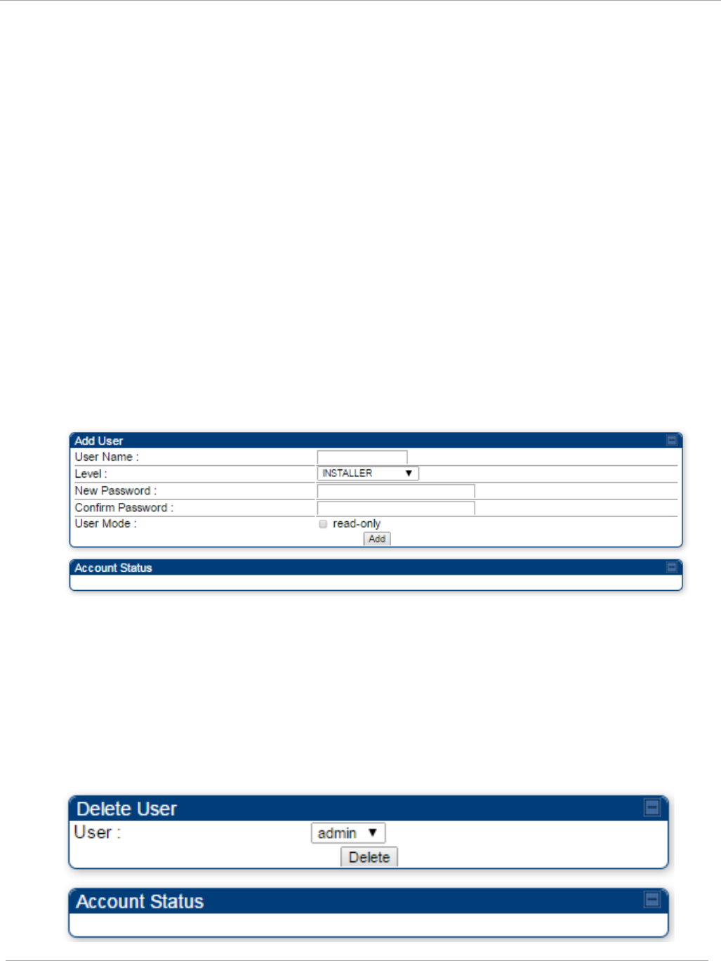
Task 5: Configuring security PMP 450i and PTP 450i Configuration and User
Guide
From the factory default state, configure passwords for both the root and admin
account at the ADMINISTRATOR permission level, using the Account, Change Users
Password tab. To change the user password, select the desired user and enter the
new password in the “New Password” field. This new password must be confirmed
in the “Confirm Password” field. To commit the password change, click "Change
Password" (If you configure only one of these, then the other will still require no
password for access into it and thus remain a security risk). If you are intent on
configuring only one of them, delete the admin account. The root account is the only
account that CNUT uses to update the module.
The User Mode is used to create an account which are mainly used for viewing the
configurations. The local and remote Read-Only user account can be created by
“Admin”, “Installer” or “Tech” logins. To create a Read-Only user, the “read-only”
check box needs to be checked.
The Read-Only user cannot perform any service impacting operations like creating
read-only accounts, editing and viewing read-only user accounts, changes in login
page, read-only user login, Telnet access, SNMP, RADIUS and upgrade/downgrade.
Figure 26 AP / SM Add User tab of account page
After a password has been set for any ADMINISTRATOR-level account, initial access
to the module GUI opens the view of GUEST level.
Deleting a User from Access to a Module
The Account => Delete User tab provides a drop down list of configured users
from which to select the user you want to delete.
Figure 27 Delete User tab of the AP / SM
pmp-0957 (April 2015) 81
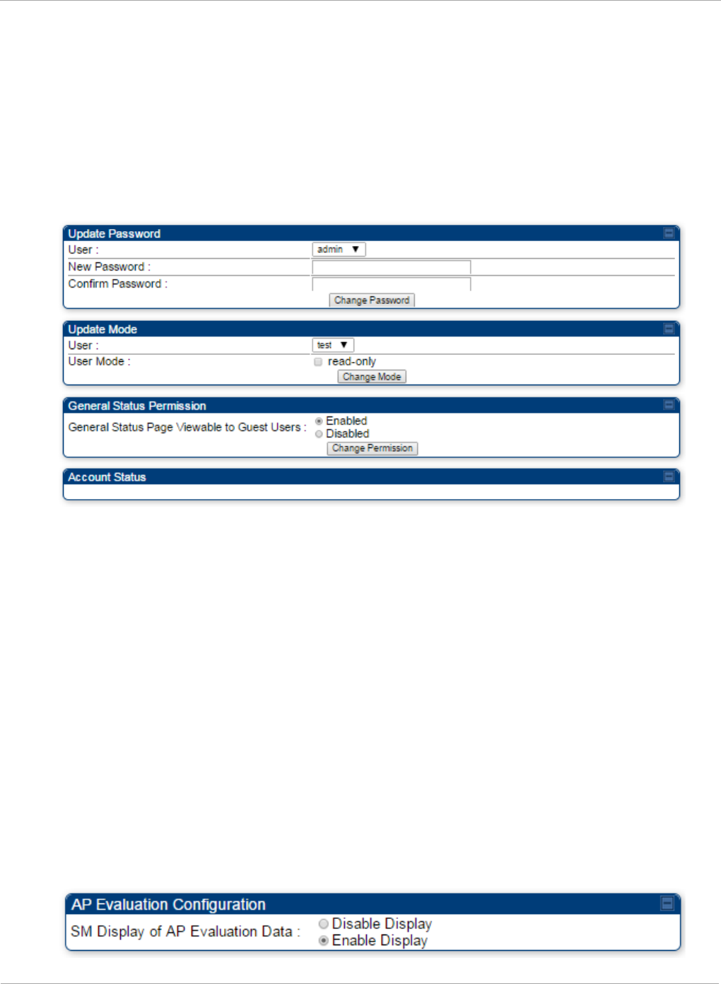
PMP 450i and PTP 450i Configuration and User
Task 5: Configuring security
Accounts that cannot be deleted are
• the current user's own account.
• the last remaining account of ADMINISTRATOR level.
Changing a User Setting
Figure 28 Change User Setting tab AP / SM
The Account => Change User Setting tab allows to update password, mode
update and general status permission for a user.
Update Password
This tab provides a drop down list of configured users from which a user is selected
to change password.
Update Mode
This tab facilitates to convert a configured user to a Read-Only user.
General Status Permission
This tab enables and disables visibility of General Status Page for all Guest user.
To display of Radio data on SMs main Login page for Guest login, it can be enabled
or disabled in Security tab of Configuration page.
Figure 29 AP Evaluation Configuration parameter of Security tab
82 pmp-0957 (April 2015)

Task 5: Configuring security PMP 450i and PTP 450i Configuration and User
Guide
Overriding Forgotten IP Addresses or Passwords on AP and SM
A small adjunctive product allows you to temporarily override some AP/SM settings
and thereby regain control of the module. This override plug is needed for access to
the module in any of the following cases:
• You have forgotten either
o the IP address assigned to the module.
o the password that provides access to the module.
• The module has been locked by the No Remote Access feature.
• You want local access to a module that has had the 802.3 link disabled in the
Configuration page.
You can configure the module such that, when it senses the override plug, it
responds by either
• resetting the LAN1 IP address to 169.254.1.1, allowing access through the default
configuration without
changing
the configuration, whereupon you is able to view and
reset any non-default values as you wish.
• resetting all configurable parameters to their factory default values.
Acquiring the Override Plug
You can either purchase or fabricate an override plug as follows. To purchase an
override plug for a nominal fee, order the plug at http://www.best-tronics.com. To
fabricate an override plug, perform the following steps.
Procedure 7 Constructing an override plug
1 Install an RJ-11 6-pin connector onto a 6-inch length of CAT 5 cable
2 Pin out all 6-pins.
3 Short (solder together) Pins 4 and 6 on the other end. Do not connect any other
wires to anything.
Figure 30 RJ-11 pin out for the override plug
Pin 1 → white / orange ← Pin 1
Pin 2 → white / green ← Pin 2
Pin 3 → white / blue ← Pin 3
Pin 4 → green ← Pin 6
Pin 5 → blue ← Pin 5
Pin 6 → orange ← Pin 4
Using the Override Plug
To regain access to the module, follow these instructions:
pmp-0957 (April 2015) 83
PMP 450i and PTP 450i Configuration and User
Task 5: Configuring security
While the override plug is connected to a module, the module can neither register
nor allow registration of another module.
Procedure 8 Using the override plug
1 Insert the override plug into the RJ-11 GPS utility port of the module.
2 Power cycle by removing, then re-inserting, the Ethernet cable.
RESULT: The module boots with the default IP address of 169.254.1.1, password
fields blank, and all other configuration values as previously set.
3 Wait approximately 30 seconds for the boot to complete.
4 Remove the override plug.
5 Set passwords and IP address as desired.
6 Change configuration values if desired.
7 Click the Save Changes button.
8 Click the Reboot button.
If "set to default upon Defalut plug insertion" is enabled, the radio will revert all of
it's settings back to factory defaults.
Requiring SM Authentication
Through the use of a shared AP key, or an external RADIUS (Remote Authentication
Dial In User Service) server, you can enhance network security by requiring SMs to
authenticate when they register.
For descriptions of each of the configurable security parameters on the AP, see
Security tab of the AP on page 93. For descriptions of each of the configurable
security parameters on the SM, see Security tab of the SM on page 100.
Operators may use the AP’s Authentication Mode field to select from among the
following authentication modes:
• Disabled—the AP requires no SMs to authenticate.
• Authentication Server —the AP requires any SM that attempts registration to be
authenticated in Wireless Manager before registration
84 pmp-0957 (April 2015)

Task 5: Configuring security PMP 450i and PTP 450i Configuration and User
Guide
• AP PreShared Key - The AP acts as the authentication server to its SMs and will
make use of a user-configurable pre-shared authentication key. The operator enters
this key on both the AP and all SMs desired to register to that AP. There is also an
option of leaving the AP and SMs at their default setting of using the “Default Key”.
Due to the nature of the authentication operation, if you want to set a specific
authentication key, then you MUST configure the key on all of the SMs and reboot
them BEFORE enabling the key and option on the AP. Otherwise, if you configure
the AP first, none of the SMs is able to register.
• RADIUS AAA - When RADIUS AAA is selected, up to 3 Authentication Server
(RADIUS Server) IP addresses and Shared Secrets can be configured. The IP
address(s) configured here must match the IP address(s) of the RADIUS server(s).
The shared secret(s) configured here must match the shared secret(s) configured in
the RADIUS server(s). Servers 2 and 3 are meant for backup and reliability, not for
splitting the database. If Server 1 doesn’t respond, Server 2 is tried, and then server
3. If Server 1 rejects authentication, the SM is denied entry to the network, and
does not progress trying the other servers. For more information on configuring the
PMP 450i network to utilize a RADIUS server, see Task 15: Configuring a RADIUS
server on page 184
Filtering protocols and ports
You can filter (block) specified protocols and ports from leaving the AP and SM and
entering the network. This protects the network from both intended and inadvertent
packet loading or probing by network users. By keeping the specified protocols or
ports off the network, this feature also provides a level of protection to users from
each other.
Protocol and port filtering is set per AP/SM. Except for filtering of SNMP ports,
filtering occurs as packets leave the AP/SM. If a SM is configured to filter SNMP,
then SNMP packets are blocked from entering the SM and, thereby, from
interacting with the SNMP portion of the protocol stack on the SM.
Port Filtering with NAT Enabled
Where NAT is enabled, you can filter only the three user-defined ports. The
following are example situations in which you can configure port filtering where
NAT is enabled.
• To block a subscriber from using FTP, you can filter Ports 20 and 21 (the FTP ports)
for both the TCP and UDP protocols.
• To block a subscriber from access to SNMP, you can filter Ports 161 and 162 (the
SNMP ports) for both the TCP and UDP protocols.
In only the SNMP case, filtering occurs before the packet interacts with the
protocol stack.
pmp-0957 (April 2015) 85

PMP 450i and PTP 450i Configuration and User
Task 5: Configuring security
Protocol and Port Filtering with NAT Disabled
Where NAT is disabled, you can filter both protocols and the three user-defined
ports. Using the check boxes on the interface, you can either
• Allow all protocols except those that you wish to block.
• Block all protocols except those that you wish to allow.
You can allow or block any of the following protocols:
• PPPoE (Point to Point Protocol over Ethernet)
• Any or all of the following IPv4 (Internet Protocol version 4) protocols:
o SMB (Network Neighborhood)
o SNMP
o Bootp Client
o Bootp Server
o Up to 3 user-defined ports
o All other IPv4 traffic (see Figure 31)
• Any or all of the following IPv6 (Internet Protocol version 6) protocols:
o SMB (Network Neighborhood)
o SNMP
o Bootp Client
o Bootp Server
o Up to 3 user-defined ports
o All other IPv6 traffic (see Figure 31)
• Filter Direction – Upstream and Downstream
• ARP (Address Resolution Protocol)
Figure 31 Categorical protocol filtering
BootP
Client
BootP
Server
SNMP
IPv4
Multica
st
User
Defined
Port 1
SMB
User
Defined
Port 3
User
Defined
Port 2
PPPoE ARP
All
Others
All
Other
IPv4
86 pmp-0957 (April 2015)

Task 5: Configuring security PMP 450i and PTP 450i Configuration and User
Guide
The following are example situations in which you can configure protocol filtering
where NAT is disabled:
• If you block a subscriber from only PPPoE and SNMP, then the subscriber retains
access to all other protocols and all ports.
• If you block PPPoE, IPv4, and Uplink Broadcast, and you also check the
All others selection, then only Address Resolution Protocol is not filtered.
For more information, see Protocol Filtering tab of the SM on Page 106.
Table 26 Ports filtered per protocol selection
Protocol Selected Port Filtered (Blocked)
SMB
Destination Ports UDP : 137, 138, 139, 445, 3702 and
1900
Destination Ports TCP : 137, 138, 139, 445, 2869,
5357 and 5358
SNMP Destination Ports TCP and UDP : 161 and 162
Bootp Client Source Port 68 UDP
Bootp Server Source Port 67 UDP
User Defined Port
1..3 User defined ports for filtering UDP and TCP
IPv4 Multicast Block IPv4 packet types except other filters defined.
IPv6 Multicast Block IPv6 packet types except other filters defined.
ARP Filter all Ethernet packet type 806
Upstream Applies packet filtering to traffic coming into the FEC
interface
Downstream Applies packet filtering to traffic destined to exit the
FEC interface
Encrypting downlink broadcasts
An AP can be enabled to encrypt downlink broadcast packets such as the following:
• ARP
• NetBIOS
• broadcast packets containing video data on UDP.
The encryption used is DES for a DES-configured module and AES for an AES-
configured module. Before the Encrypt Downlink Broadcast feature is enabled on
the AP, air link security must be enabled on the AP.
pmp-0957 (April 2015) 87

PMP 450i and PTP 450i Configuration and User
Task 5: Configuring security
Isolating SMs
In an AP, you can prevent SMs in the sector from directly communicating with each
other. In CMMmicro Release 2.2 or later and the CMM4, you can prevent connected
APs from directly communicating with each other, which prevents SMs that are in
different sectors of a cluster from communicating with each other.
In the AP, the SM Isolation parameter is available in the General tab of the
Configuration web page. In the drop-down menu for that parameter, you can
configure the SM Isolation feature by any of the following selections:
• Disable SM Isolation (the default selection). This allows full communication
between SMs.
• Block SM Packets from being forwarded. This prevents both multicast/broadcast
and unicast SM-to-SM communication.
• Block and Forward SM Packets to Backbone. This not only prevents
multicast/broadcast and unicast SM-to-SM communication but also sends the
packets, which otherwise are handled SM to SM, through the Ethernet port of the
AP.
In the CMMmicro and the CMM4, SM isolation treatment is the result of how you
choose to manage the port-based VLAN feature of the embedded switch, where you
can switch all traffic from any AP to an uplink port that you specify. However, this is
not packet level switching. It is not based on VLAN IDs. See the VLAN Port
Configuration parameter in the dedicated user guide that supports the CMM
product that you are deploying.
Filtering management through Ethernet
You can configure the SM to disallow any device that is connected to its Ethernet
port from accessing the IP address of the SM. If you set the Ethernet Access
Control parameter to Enabled, then
• no attempt to access the SM management interface (by HTTP, SNMP, FTP, or
TFTP) through Ethernet can succeed.
• any attempt to access the SM management interface over the air (by IP address,
presuming that LAN1 Network Interface Configuration, Network Accessibility
is set to Public, or by link from the Session Status or Remote Subscribers tab in the
AP) is unaffected.
Allowing management only from specified IP addresses
The Security tab of the Configuration web page in the AP and SM includes the IP
Access Control parameter. You can specify one, two, or three IP addresses that
must be allowed to access the management interface (by HTTP, SNMP, FTP, or
TFTP).
If you select
88 pmp-0957 (April 2015)

Task 5: Configuring security PMP 450i and PTP 450i Configuration and User
Guide
• IP Access Filtering Disabled, then management access is allowed from any IP
address, even if the Allowed Source IP
1 to 3
parameters are populated.
• IP Access Filtering Enabled, and specify at least one address in the Allowed
Source IP
1 to 3
parameter, then management access is limited to the specified
address(s). If you intend to use Wireless Manager to manage the element, then you
must ensure that the IP address of the Wireless Manager server is listed here.
Configuring management IP by DHCP
The IP tab in the Configuration web page of every radio contains a LAN1 Network
Interface Configuration, DHCP State parameter that, if enabled, causes the IP
configuration (IP address, subnet mask, and gateway IP address) to be obtained
through DHCP instead of the values of those individual parameters. The setting of
this DHCP state parameter is also viewable, but is not settable, in the Network
Interface tab of the Home page.
In the SM, this parameter is settable
• in the NAT tab of the Configuration web page, but only if NAT is enabled.
• in the IP tab of the Configuration web page, but only if the Network Accessibility
parameter in the IP tab is set to Public.
Restricting radio Telnet access over the RF interface
RF Telnet Access restricts Telnet access to the AP from a device situated below a
network SM (downstream from the AP). This is a security enhancement to restrict
RF-interface sourced AP access specifically to the LAN1 IP address and LAN2 IP
address (Radio Private Address, typically 192.168.101.[LUID]). This restriction
disallows unauthorized users from running Telnet commands on the AP that can
change AP configuration or modifying network-critical components such as routing
and ARP tables.
The RF Telnet Access may be configured via the AP GUI or via SNMP commands,
and RF Telnet Access is set to “Enabled” by default. Once RF Telnet Access is set to
“Disabled”, if there is a Telnet session attempt to the AP originating from a device
situated below the SM (or any downstream device), the attempt is dropped. This
also includes Telnet session attempts originated from the SM’s management
interface (if a user has initiated a Telnet session to a SM and attempts to Telnet
from the SM to the AP). In addition, if there are any active Telnet connections to
the AP originating from a device situated below the SM (or any downstream device),
the connection is dropped. This behavior must be considered if system
administrators use Telnet downstream from an AP (from a registered SM) to modify
system parameters.
Setting RF Telnet Access to “Disabled” does not affect devices situated above the AP
from accessing the AP via Telnet, including servers running the CNUT (Canopy
Network Updater tool) application. Also, setting RF Telnet Access to “Disabled”
does not affect any Telnet access into upstream devices (situated above or adjacent
to the AP) through the AP (see Figure 32).
pmp-0957 (April 2015) 89
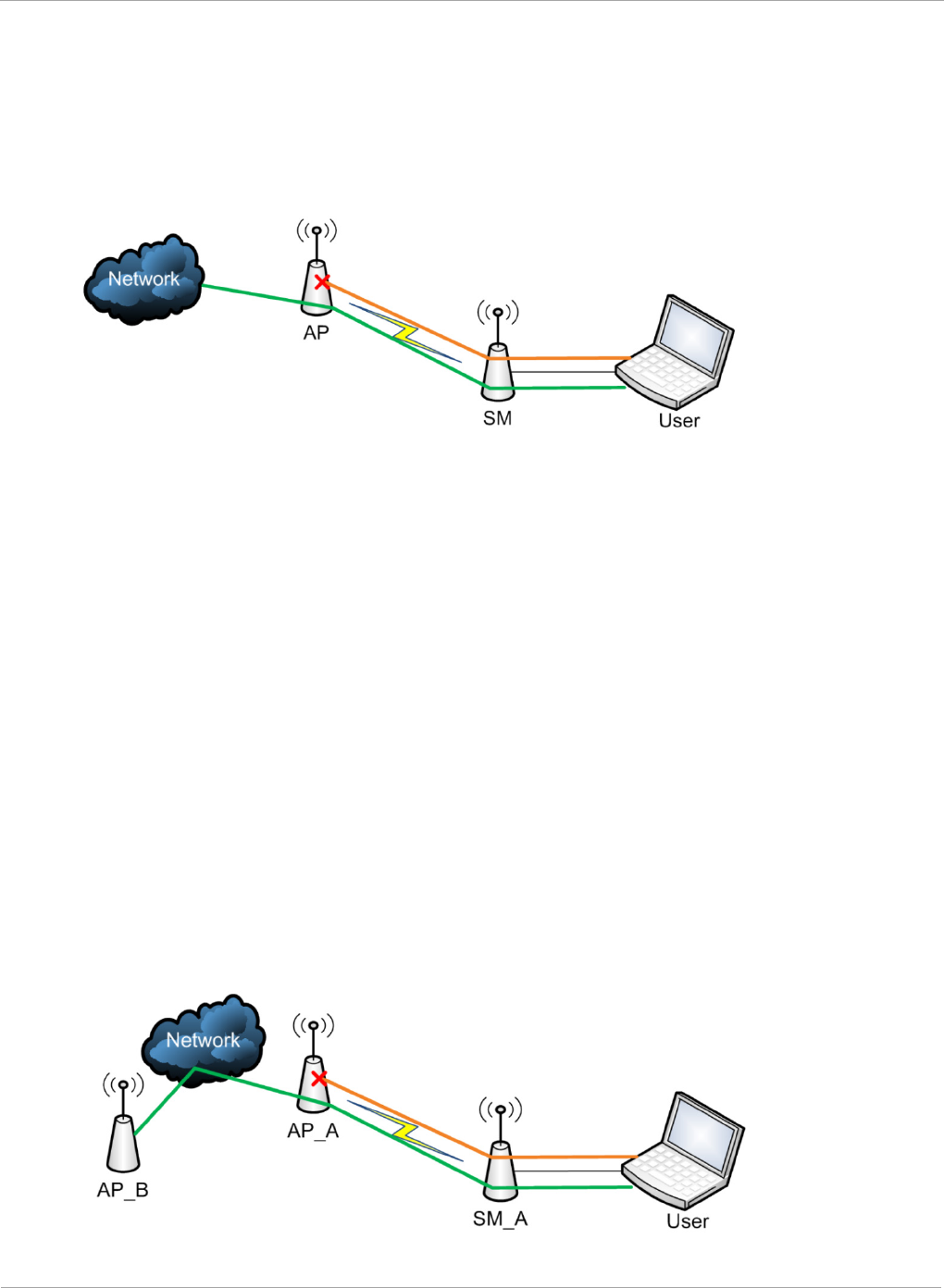
PMP 450i and PTP 450i Configuration and User
Task 5: Configuring security
The figure below depicts a user attempting two telnet sessions. One is targeted for
the AP (orange) and one is targeted for the network upstream from the AP (green).
If RF Telnet Access is set to “Disabled”, the Telnet attempt from the user to the AP
is blocked, but the attempt from the user to Network is allowed to pass through the
Cambium network.
Figure 32 RF Telnet Access Restrictions (orange) and Flow through (green)
Key Security Considerations when using the RF Telnet Access
Feature
To ensure that the network is fully protected from unauthorized AP Telnet sessions,
the following topics must be considered:
Securing AP Clusters
When working with a cluster of AP units, to eliminate potential security holes
allowing Telnet access, ensure that the RF Telnet Access parameter is set to
“Disabled” for every AP in the cluster. In addition, since users situated below the
AP are able to pass Telnet sessions up through the SM and AP to the upstream
network (while AP RF Telnet Access is set to “Disabled”), ensure that all
CMM3/CMM4 or other networking equipment is secured with strong passwords.
Otherwise, users may Telnet to the CMM3/CMM4 or other networking equipment,
and subsequently access network APs (see Figure 33) via their Ethernet interfaces
(since RF Telnet Access only prevents Telnet sessions originating from the AP’s
wireless interface).
Figure 33 RF Telnet Access Restriction (orange) and Potential Security Hole
(green)
90 pmp-0957 (April 2015)
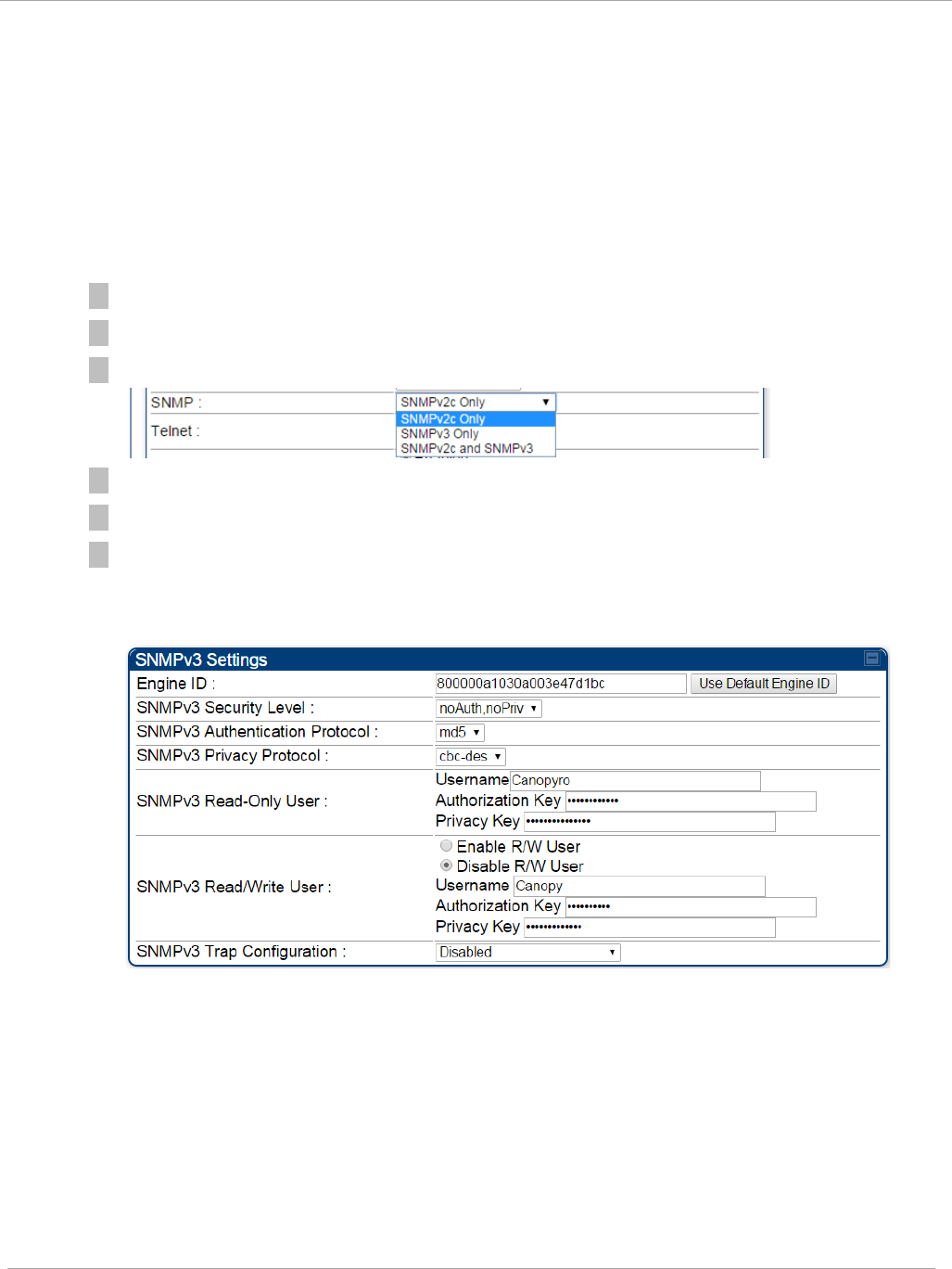
Task 5: Configuring security PMP 450i and PTP 450i Configuration and User
Guide
As a common practice, AP administrator usernames and passwords must be secured
with strong, non-default passwords.
Securing SNMP Access
The SNMPv3 provides a more secure method to perform SNMP operations. This
standard provides services for authentication, data integrity and message
encryption over SNMP.
Procedure 9 Configuring SNMPv3
1 Log into the AP GUI using administrator credentials
2 On the AP/SM GUI, navigate to Configuration => Security Page
3 Under GUI heading “Security Mode”, set SNMP to SNMPv3 Only
4 Click the Save Changes button
5 Go to Configuration => SNMP Page
6 Under GUI heading “SNMPv3 setting”, set Engine ID, SNMPv3 Security
Level, SNMPv3 Authentication Protocol, SNMPv3 Privacy Protocol,
SNMPv3 Read-Only User, SNMPv3 Read/Write User, SNMPv3 Trap
Configuration parameters:
Engine ID :
Each radio (AP or SM) has a distinct SNMP authoritative engine identified by a
unique Engine ID. While the Engine ID is configurable to the operator it is
expected that the operator follow the guidelines of the SNMPEngineID defined
in the SNMP-FRAMEWORK-MIB (RFC 3411). The default Engine ID is the MAC
address of the device.
SNMPv3 security level, Authentication and Privacy Protocol
The authentication allows authentication of SNMPv3 user and privacy allows for
encryption of SNMPv3 message. PMP 450i supports MD5 authentication and
CBC-DES privacy protocols.
pmp-0957 (April 2015) 91
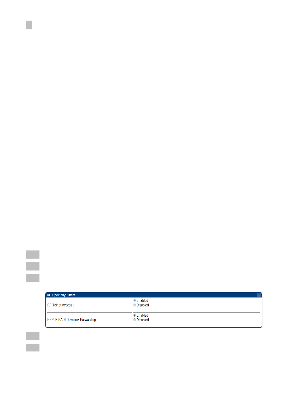
PMP 450i and PTP 450i Configuration and User
Task 5: Configuring security
SNMPv3 Read-Only and Read/Write User
The user can defined by configurable attributes. The attributes and default
values are:
• Read-only user
o Username = Canopyro
o Authentication Password = authCanopyro
o Privacy Password = privacyCanopyro
• Read-write user (by default read-write user is disabled)
o Username = Canopy
o Authentication Password = authCanopy
o Privacy Password = privacyCanopy
SNMPv3 Trap Configuration
The traps may be sent from radios in SNMPv3 format based on parameter
settings. It can be configured for Disabled, Enabled for Read-Only User, Enable
for Read/Write User.
Restricting AP RF Telnet Access
AP Telnet access via the RF interface may be configured in two ways – the AP GUI
and SNMP.
Controlling RF Telnet Access via the AP GUI
To restrict all Telnet access to the AP via the RF interface from downstream devices,
follow these instructions using the AP GUI:
Procedure 10 Restricting RF Telnet access
1 Log into the AP GUI using administrator credentials
2 On the AP GUI, navigate to Configuration => Protocol Filtering
3 Under GUI heading “Telnet Access over RF Interface”, set RF Telnet Access to
Disabled
4 Click the Save button
5 Once the Save button is clicked, all RF Telnet Access to the AP from devices
situated below the AP is blocked.
92 pmp-0957 (April 2015)
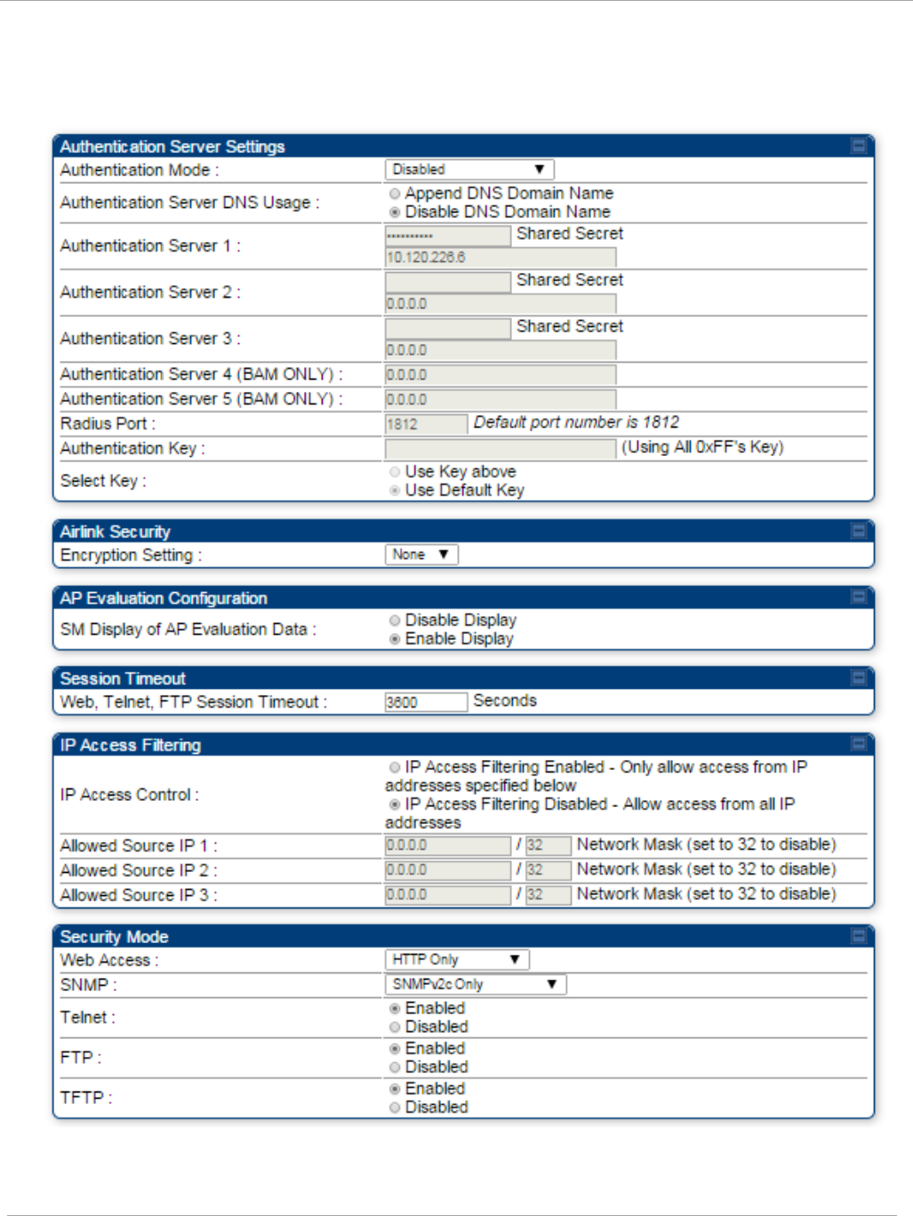
Task 5: Configuring security PMP 450i and PTP 450i Configuration and User
Guide
Security tab of the AP
Figure 34 Security tab of the AP
pmp-0957 (April 2015) 93

PMP 450i and PTP 450i Configuration and User
Task 5: Configuring security
In the Security tab of the AP, you may set the following parameters.
Table 27 AP Security attributes
Attribute Meaning
Authentication Mode Operators may use this field to select from among the following
authentication modes:
Disabled—the AP requires no SMs to authenticate.
Authentication Server —the AP requires any SM that
attempts registration to be authenticated in Wireless Manager
before registration.
AP PreShared Key - The AP acts as the authentication server
to its SMs and will make use of a user-configurable pre-shared
authentication key. The operator enters this key on both the AP
and all SMs desired to register to that AP. There is also an
option of leaving the AP and SMs at their default setting of
using the “Default Key”. Due to the nature of the
authentication operation, if you want to set a specific
authentication key, then you MUST configure the key on all of
the SMs and reboot them BEFORE enabling the key and option
on the AP. Otherwise, if you configure the AP first, none of the
SMs is able to register.
RADIUS AAA - When RADIUS AAA is selected, up to 3
Authentication Server (RADIUS Server) IP addresses and
Shared Secrets can be configured. The IP address(s)
configured here must match the IP address(s) of the RADIUS
server(s). The shared secret(s) configured here must match the
shared secret(s) configured in the RADIUS server(s). Servers 2
and 3 are meant for backup and reliability, not for splitting the
database. If Server 1 doesn’t respond, Server 2 is tried, and
then server 3. If Server 1 rejects authentication, the SM is
denied entry to the network, and does not progress trying the
other servers.
Authentication Server
DNS Usage
The management DNS domain name may be toggled such that
the name of the authentication server only needs to be specified
and the DNS domain name is automatically appended to that
name.
Authentication Server
1 to 5
Enter the IP address or server name of the authentication
server (RADIUS or WM) and the Shared Secret configured in
the authentication server. When Authentication Mode
RADIUS AAA is selected, the default value of Shared Secret
is “CanopySharedSecret”. The Shared Secret may consist of
up to 32 ASCII characters.
Radius Port This field allows the operator to configure a custom port for
RADIUS server communication. The default value is
1812
.
94 pmp-0957 (April 2015)

Task 5: Configuring security PMP 450i and PTP 450i Configuration and User
Guide
Attribute Meaning
Authentication Key The authentication key is a 32-character hexadecimal string
used when Authentication Mode is set to AP PreShared Key.
By default, this key is set to
0xFFFFFFFFFFFFFFFFFFFFFFFFFFFFFFFF.
Select Key
This option allows operators to choose which authentication key
is used:
Use Key above means that the key specified in
Authentication Key is used for authentication
Use Default Key means that a default key (based off of the
SM’s MAC address) is used for authentication
Encryption Setting
Specify the type of airlink security to apply to this AP. The
encryption setting must match the encryption setting of the
SMs.
None provides no encryption on the air link.
DES (Data Encryption Standard): An over-the-air link
encryption option that uses secret 56-bit keys and 8 parity bits.
DES performs a series of bit permutations, substitutions, and
recombination operations on blocks of data. DES encryption
does not affect the performance or throughput of the system.
AES (Advanced Encryption Standard): An over-the-air link
encryption option that uses the Rijndael algorithm and 128-bit
keys to establish a higher level of security than DES. AES
products are certified as compliant with the Federal
Information Processing Standards (FIPS 197) in the U.S.A.
SM Display of AP
Evaluation Data
You can use this field to suppress the display of data about this
AP on the AP Evaluation tab of the Tools page in all SMs that
register.
Web, Telnet, FTP
Session Timeout
Enter the expiry in seconds for remote management sessions
via HTTP, telnet, or ftp access to the AP.
IP Access Control You can permit access to the AP from any IP address (IP
Access Filtering Disabled) or limit it to access from only one,
two, or three IP addresses that you specify (IP Access
Filtering Enabled). If you select IP Access Filtering
Enabled, then you must populate at least one of the three
Allowed Source IP parameters or have no access permitted
from any IP address
pmp-0957 (April 2015) 95

PMP 450i and PTP 450i Configuration and User
Task 5: Configuring security
Attribute Meaning
Allowed Source IP
1
to 3
If you selected IP Access Filtering Enabled for the IP Access
Control parameter, then you must populate at least one of the
three Allowed Source IP parameters or have no access
permitted to the AP from any IP address. You may populate as
many as all three.
If you selected IP Access Filtering Disabled for the IP
Access Control parameter, then no entries in this parameter
are read, and access from all IP addresses is permitted.
Web Access The Radio supports secured and non-secured web access
protocols. Select suitable web access from drop down list:
• HTTP Only – provides non-secured web access. The radio
to be accessed via http://<IP of Radio>.
• HTTPs Only – provides a secured web access. The radio to
be accessed via http://<IP of Radio>.
• HTTP and HTTPs – If enabled, the radio can be accessed
via both http and https.
SNMP This option allows to configure SNMP agent communication
version. It can be selected from drop down list :
• SNMPv2c Only – Enables SNMP v2 community protocol.
• SNMPv3 Only – Enables SNMP v3 protocol. It is secured
communication protocol.
• SNMPv2c and SNMPv3 – It enables both the protocols.
Telnet This option allows to Enable and Disable Telnet access to the
Radio.
FTP This option allows to Enable and Disable FTP access to the
Radio.
TFTP This option allows to Enable and Disable TFTP access to the
Radio.
96 pmp-0957 (April 2015)
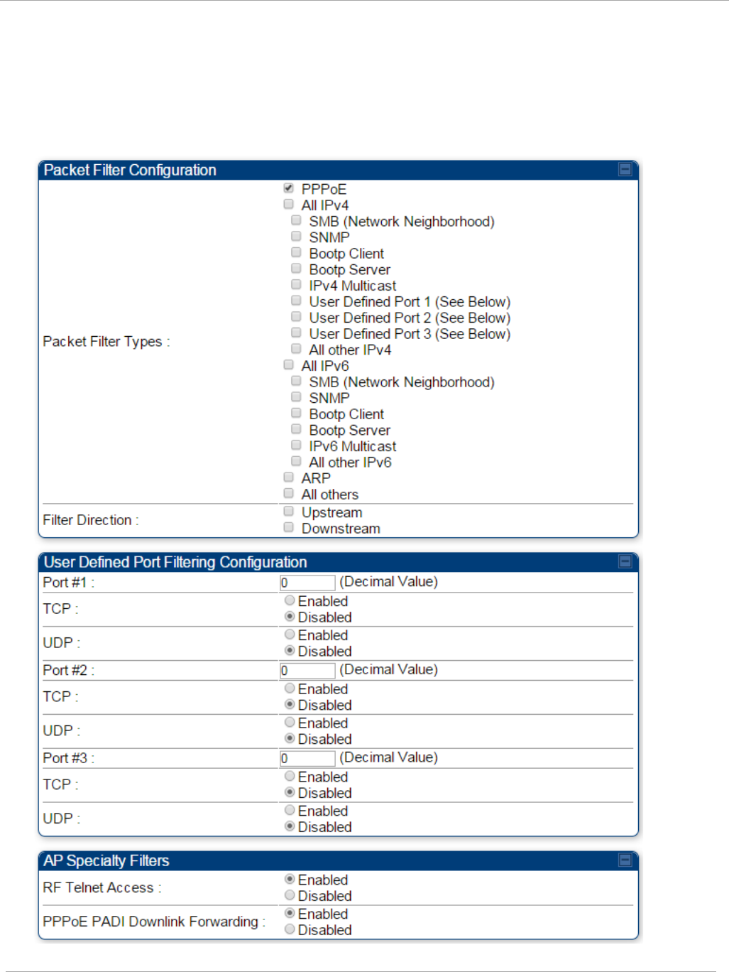
Task 5: Configuring security PMP 450i and PTP 450i Configuration and User
Guide
Filtering protocols and ports
Protocol Filtering tab of the AP
Figure 35 Protocol Filtering tab of the AP
pmp-0957 (April 2015) 97

PMP 450i and PTP 450i Configuration and User
Task 5: Configuring security
In the Protocol Filtering tab of the AP, you may set the following parameters.
Table 28 AP Protocol Filtering attributes
Attribute Meaning
Packet Filter Types
For any box selected, the Protocol and Port Filtering feature
blocks the associated protocol type.
To filter packets in any of the user-defined ports, you must do
all of the following:
Check the box for User Defined Port
n
(See Below) in the
Packet Filter Types section of this tab.
In the User Defined Port Filtering Configuration section of
this tab:
• provide a port number at Port #
n
.
• enable TCP and/or UDP by clicking the associated radio
button
Filter Direction Operators may choose to filter upstream (uplink) RF packets or
downstream (downlink) RF packets.
User Defined Port
Filtering Configuration
You can specify ports for which to block subscriber access,
regardless of whether NAT is enabled.
RF Telnet Access RF Telnet Access restricts Telnet access to the AP from a
device situated below a network SM (downstream from the
AP). This is a security enhancement to restrict RF-interface
sourced AP access specifically to the LAN1 IP address and
LAN2 IP address (Radio Private Address, typically
192.168.101.[LUID]). This restriction disallows unauthorized
users from running Telnet commands on the AP that can
change AP configuration or modifying network-critical
components such as routing and ARP tables.
PPPoE PADI Downlink
Forwarding
Enabled: the AP allows downstream and upstream
transmission of PPPoE PADI packets. By default, PPPoE PADI
Downlink Forwarding is set to “Enabled”.
Disabled: the AP disallows PPPoE PADI packets from entering
the Ethernet interface and exiting the RF interface
(downstream to the SM). PPPoE PADI packets are still allowed
to enter the AP’s RF interface and exit the AP’s Ethernet
interface (upstream).
98 pmp-0957 (April 2015)
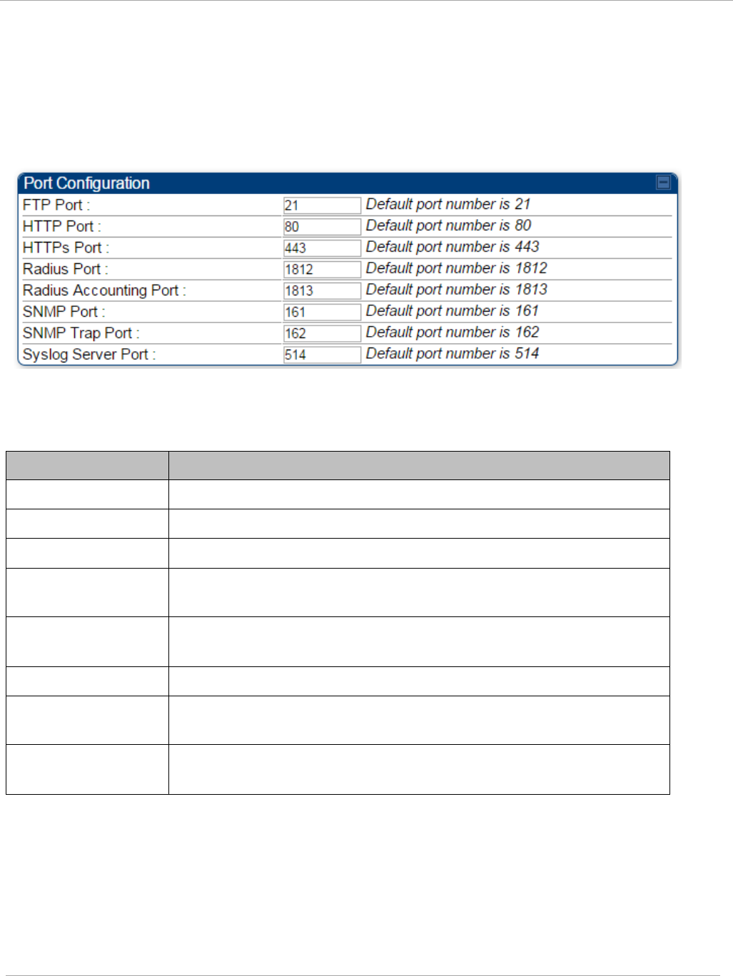
Task 5: Configuring security PMP 450i and PTP 450i Configuration and User
Guide
Port configuration tab of the AP
PMP 450i devices support access to various communication protocols and only the ports
required for these protocols are available for access by external entities. Operators may
change the port numbers for these protocols via the radio GUI or SNMP.
Figure 36 Port Configuration tab of the AP
In the Port Configuration tab of the AP, you may set the following parameters.
Table 29 AP Port Configuration attributes
Attribute Meaning
FTP Port The listen port on the device used for FTP communication.
HTTP Port The listen port on the device used for HTTP communication.
HTTPs Port The listen port on the device used for HTTPS communication
Radius Port The destination port used by the device for RADIUS
communication.
Radius Accounting
Port
The destination port used by the device for RADIUS accounting
communication.
SNMP Port The listen port on the device used for SNMP communication.
SNMP Trap Port The destination port used by the device to which SNMP traps are
sent.
Syslog Server Port The destination port used by the device to which Syslog
messaging is sent.
pmp-0957 (April 2015) 99
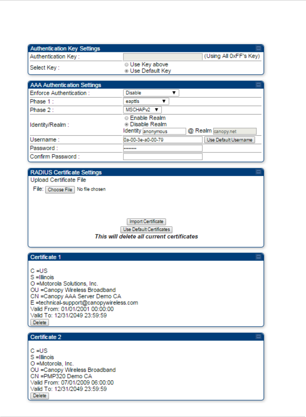
PMP 450i and PTP 450i Configuration and User
Task 5: Configuring security
Security tab of the SM
Figure 37 Security tab of the SM
100 pmp-0957 (April 2015)
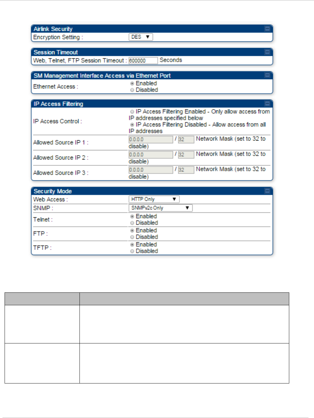
Task 5: Configuring security PMP 450i and PTP 450i Configuration and User
Guide
Continue…
In the Security tab of the SM, you may set the following parameters.
Table 30 SM Security attributes
Attribute Meaning
Authentication Key Only if the AP to which this SM will register requires
authentication, specify the key that the SM will use when
authenticating. For alpha characters in this hex key, use only
upper case.
Select Key
The Use Default Key selection specifies the predetermined key
for authentication in Wireless Manager
The Use Key above selection specifies the 32-digit hexadecimal
key that is permanently stored on both the SM and the WM
pmp-0957 (April 2015) 101

PMP 450i and PTP 450i Configuration and User
Task 5: Configuring security
Attribute Meaning
Enforce
Authentication
The SM may enforce authentication types of AAA and AP Pre-
sharedKey. The SM will not finish the registration process if
the AP is not using the configured authentication method (and
the SM locks out the AP for 15 minutes).
Phase 1 The protocols supported for the Phase 1 (Outside Identity)
phase of authentication are
EAPTTLS (Extensible
Authentication Protocol Tunneled Transport Layer
Security) or
MSCHAPv2 (Microsoft Challenge-Handshake Authentication
Protocol version 2).
Phase 2 Select the desired Phase 2 (Inside Identity) authentication
protocol from the Phase 2 options of PAP (Password
Authentication Protocol), CHAP (Challenge Handshake
Authentication
Protocol), and MSCHAP (Microsoft’s version of
CHAP, version 2 is used). The protocol
must
be
consistent with
the authentication protocol configured on the RADIUS
server.
Identity/Realm If Realms are being used, select Enable Realm and configure
an outer identity in the
Identity
field and a Realm in the
Realm field. These must match the Phase 1/Outer Identity and
Realm
configured in the RADIUS server. The default Identity
is “anonymous”. The Identity can be
up
to
128 non-special (no
diacritical markings) alphanumeric characters. The default
Realm
is
“canopy.net”. The Realm can also be up to 128 non-
special alphanumeric
characters.
Configure an outer Identity in the Username field. This must
match the Phase
1/Outer
Identity username configured in the
RADIUS server. The default Phase 1/Outer
Identity
Username
is “anonymous”. The Username can be up to 128 non-special
(no
diacritical
markings) alphanumeric
characters.
Username Enter a Username for the SM. This must match the username
configured for the SM on
the
RADIUS server. The default
Username is the SM’s MAC address. The Username can be
up
to
128 non-special (no diacritical markings) alphanumeric
characters.
Password Enter the desired password for the SM in the Password and
Confirm Password fields..
The
Password must match the
password configured for the SM on the RADIUS server.
The
default Password is “password”. The Password can be up to
128 non-special (no
diacritical
markings) alphanumeric
characters
102 pmp-0957 (April 2015)

Task 5: Configuring security PMP 450i and PTP 450i Configuration and User
Guide
Attribute Meaning
Upload Certificate
File
To upload a certificate manually to a SM, first load it in a
known place on your PC
or
network
drive, then click on a
Delete button on one of the Certificate description blocks to
delete a certificate to provide space for your certificate. Click
on Choose File, browse to
the
location of the certificate, and
click the Import Certificate button, and then reboot the radio
to use the new certificate.
When a certificate is in use, after the SM successfully registers
to an AP, an indication of In
Use
will appear in the description
block of the certificate being
used.
The public certificates installed on the SMs are used with the
private certificate on the
RADIUS
server to provide a
public/private key encryption
system.
Up to 2 certificates can be resident on a SM. An installed
certificate can be deleted
by
clicking the Delete button in the
certificate’s description block on the Configuration >
Security
tab. To restore fhe 2 default certificates, click the Use Default
Certificates button in
the
RADIUS Certificate Settings
parameter block and reboot the
radio.
Encryption Setting Specify the type of airlink security to apply to this SM. The
encryption setting must match the encryption setting of the AP.
None provides no encryption on the air link.
DES (Data Encryption Standard): An over-the-air link
encryption option that uses secret 56-bit keys and 8 parity bits.
DES performs a series of bit permutations, substitutions, and
recombination operations on blocks of data. DES encryption
does not affect the performance or throughput of the system.
AES (Advanced Encryption Standard): An over-the-air link
encryption option that uses the Rijndael algorithm and 128-bit
keys to establish a higher level of security than DES. AES
products are certified as compliant with the Federal Information
Processing Standards (FIPS 197) in the U.S.A.
Web, Telnet, FTP
Session Timeout
Enter the expiry in seconds for remote management sessions via
HTTP, telnet, or FTP access to the SM.
pmp-0957 (April 2015) 103

PMP 450i and PTP 450i Configuration and User
Task 5: Configuring security
Attribute Meaning
Ethernet Access
If you want to prevent any device that is connected to the
Ethernet port of the SM from accessing the management
interface of the SM, select Ethernet Access Disabled. This
selection disables access through this port to via HTTP (the
GUI), SNMP, telnet, FTP, and TFTP. With this selection,
management access is available through only the RF interface
via either an IP address (if Network Accessibility is set to
Public on the SM) or the Session Status or Remote Subscribers
tab of the AP.
This setting does not prevent a device connected to the
Ethernet port from accessing the management interface of
other SMs
in the network. To prevent this, use the IP
Access Filtering Enabled selection in the IP Access
Control parameter of the SMs in the network. See IP
Access Control below.
If you want to allow management access through the Ethernet
port, select Ethernet Access Enabled. This is the factory
default setting for this parameter.
IP Access Control You can permit access to the SM from any IP address (IP
Access Filtering Disabled) or limit it to access from only one,
two, or three IP addresses that you specify (IP Access Filtering
Enabled). If you select IP Access Filtering Enabled, then you
must populate at least one of the three Allowed Source IP
parameters or have no access permitted from any IP address
Allowed Source IP
1
to 3
If you selected IP Access Filtering Enabled for the IP Access
Control parameter, then you must populate at least one of the
three Allowed Source IP parameters or have no access
permitted to the SM from any IP address. You may populate as
many as all three.
If you selected IP Access Filtering Disabled for the IP Access
Control parameter, then no entries in this parameter are read,
and access from all IP addresses is permitted.
A subnet mask may be defined for each entry to allow for
filtering control based on a range of IP addresses.
104 pmp-0957 (April 2015)

Task 5: Configuring security PMP 450i and PTP 450i Configuration and User
Guide
Attribute Meaning
Web Access The Radio supports secured and non-secured web access
protocols. Select suitable web access from drop down list:
• HTTP Only – provides non-secured web access. The radio to
be accessed via http://<IP of Radio>.
• HTTPs Only – provides a secured web access. The radio to
be accessed via http://<IP of Radio>.
• HTTP and HTTPs – If enabled, the radio can be accessed
via both http and https.
SNMP This option allows to configure SNMP agent communication
version. It can be selected from drop down list :
• SNMPv2c Only – Enables SNMP v2 community protocol.
• SNMPv3 Only – Enables SNMP v3 protocol. It is secured
communication protocol.
• SNMPv2c and SNMPv3 – It enables both the protocols.
Telnet This option allows to Enable and Disable Telnet access to the
Radio.
FTP This option allows to Enable and Disable FTP access to the
Radio.
TFTP This option allows to Enable and Disable TFTP access to the
Radio.
pmp-0957 (April 2015) 105
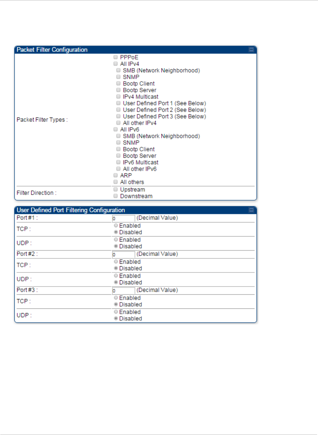
PMP 450i and PTP 450i Configuration and User
Task 5: Configuring security
Protocol Filtering tab of the SM
Figure 38 Protocol Filtering tab of the SM
106 pmp-0957 (April 2015)

Task 5: Configuring security PMP 450i and PTP 450i Configuration and User
Guide
In the Protocol Filtering tab of the SM, you may set the following parameters.
Table 31 SM Protocol Filtering attributes
Attribute Meaning
Packet Filter Types
For any box selected, the Protocol and Port Filtering feature
blocks the associated protocol type.
To filter packets in any of the user-defined ports, you must do all
of the following:
Check the box for User Defined Port
n
(See Below) in the
Packet Filter Types section of this tab.
In the User Defined Port Filtering Configuration section of
this tab:
• provide a port number at Port #
n
.
• enable TCP and/or UDP by clicking the associated radio
button
If the DHCP state parameter is set to Enabled in the
Configuration => IP tab of the SM,
do not
check the Bootp
Client option for Packet Filter Types in its Protocol Filtering
tab, because doing so blocks the DHCP request. (Filters apply to
all packets that leave the SM via its RF interface, including
those that the SM itself generates.) If you want to keep DHCP
enabled and avoid the blocking scenario, select the Bootp
Server option instead. This will result in responses being
appropriately filtered and discarded.
User Defined Port
Filtering
Configuration
You can specify ports for which to block subscriber access,
regardless of whether NAT is enabled.
pmp-0957 (April 2015) 107
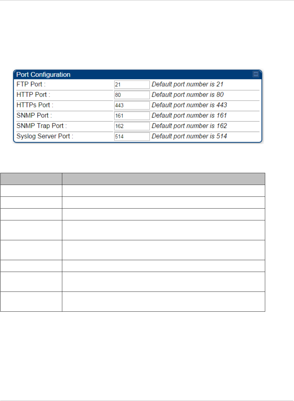
PMP 450i and PTP 450i Configuration and User
Task 5: Configuring security
Port Configuration tab of the SM
PMP 450i devices support access to various communication protocols and only the ports
required for these protocols are available for access by external entities. Operators may
change the port numbers for these protocols via the radio GUI or SNMP.
Figure 39 Port Configuration tab of the SM
In the Port Configuration tab of the SM, you may set the following parameters.
Table 32 SM Port Configuration attributes
Attribute Meaning
FTP Port The listen port on the device used for FTP communication.
HTTP Port The listen port on the device used for HTTP communication.
HTTPs Port The listen port on the device used for HTTPS communication
Radius Port This field allows the operator to configure a custom port for
RADIUS server communication. The default value is
1812
.
Radius Accounting
Port
The destination port on the AAA server used for Radius accounting
communication.
SNMP Port The listen port on the device used for SNMP communication.
SNMP Trap Port The destination port used on the device to which SNMP traps are
sent.
Syslog Server Port The syslog server port (default 514) to which syslog messaging is
sent.
108 pmp-0957 (April 2015)
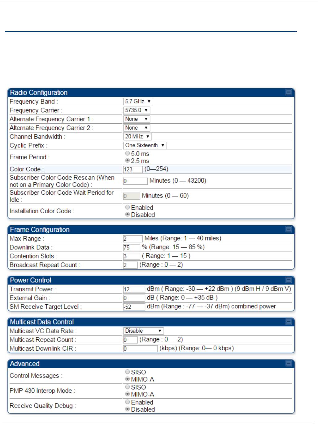

PMP 450i and PTP 450i Configuration and User
Task 6: Configuring radio parameters
Only the frequencies available for your region and the selected Channel bandwidth
(5/10/20) are displayed.
The Radio tab of the AP contains some of the configurable parameters that define how an
AP operates.
Table 33 AP Radio attributes
Attribute Meaning
Radio Mode Reserved for future modes of operation.
Frequency Band Select the desired operating frequency band.
Frequency
Carrier
Specify the frequency for the module to transmit. The default for this
parameter is None. For a list of channels in the band, see the drop-
down list on the radio GUI.
Alternate
Frequency
Carrier 1 and 2
These parameters are displayed based on Regional Settings. Refer
Country
on page 64
Channel
Bandwidth
The channel size used by the radio for RF transmission. The setting
for the channel bandwidth must match between the AP and the SM.
The supported Channel Bandwidths are 5, 10 and 20 MHz.
Cyclic Prefix OFDM technology uses a cyclic prefix, where a portion of the end of a
symbol (slot) is repeated at the beginning of the symbol to allow
multi-pathing to settle before receiving the desired data. A 1/16
cyclic prefix means that for every 16 bits of throughput data
transmitted, an additional bit is used.
Frame Period Select the Frame Period in of the radio. The support Frame Periods
are :
• 2.5 ms
Color Code
Specify a value from 0 to 254. For registration to occur, the color
code of the SM and the AP
must
match. Color code is not a security
feature. Instead, color code is a management feature, typically for
assigning each sector a different color code.
Color code allows you to force a SM to register to only a specific AP,
even where the SM can communicate with multiple APs. The default
setting for the color code value is 0. This value matches only the
color code of 0 (
not
all 255 color codes).
110 pmp-0957 (April 2015)

Task 6: Configuring radio parameters PMP 450i and PTP 450i Configuration and User
Guide
Attribute Meaning
Subscriber Color
Code Rescan
(When not on a
Primary Color
Code)
This timer may be utilized to initiate SM rescans in order to register
to an AP configured with the SM‘s primary color code.
The time (in minutes) for a subscriber to rescan (if this AP is not
configured with the SM‘s primary color code). This timer will only
fire once – if the Subscriber Color Code Wait Period for Idle
timer is configured with a nonzero value and the Subscriber Color
Code Rescan expires, the Subscriber Color Code Wait Period for
Idle is started. If the Subscriber Color Code Wait Period for Idle
timer is configured with a zero value and the Subscriber Color
Code Rescan timer expires, the SM will immediately go into rescan
mode
Subscriber Color
Code Wait
Period for Idle
The time (in minutes) for a subscriber to rescan while idle (if this AP
is not configured with the SM’s primary color code). This timer will
fire periodic events. The fired event determines if any RF unicast
traffic (either inbound or outbound) has occurred since the last
event. If the results of the event determine that no RF unicast traffic
has occurred (SM is idle), then the subscriber will rescan.
Installation
Color Code
With this feature enabled on the AP and SM, operators may install
and remotely configure SMs without having to configure matching
color codes between the modules. While the SM is accessible for
configuration from above the AP (for remote provisioning) and below
the SM (for local site provisioning), no user data is passed over the
radio link. When using the Installation Color Code feature, ensure
that the SM is configured with the factory default Color Code
configuration (Color Code 1 is “0”, Color Code 2-10 set to “0” and
“Disable”). The status of the Installation Color Code can be viewed on
the AP Eval web GUI page, and when the SM is registered using the
Installation Color Code the message “SM is registered via ICC –
Bridging Disabled!” is displayed in red on every SM GUI page. The
Installation Color Code parameter is configurable without a radio
reboot for both the AP and SM. If a SM is registered via Installation
Color Code and the feature is then disabled, operators will need to
reboot the SM or force it to reregister (i.e. using Rescan APs
functionality on the AP Eval page).
pmp-0957 (April 2015) 111

PMP 450i and PTP 450i Configuration and User
Task 6: Configuring radio parameters
Attribute Meaning
Max Range
Enter a number of miles (or kilometers divided by 1.61, then rounded
to an integer) for the furthest distance from which a SM is allowed to
register to this AP. Do not set the distance to any greater number of
miles. A greater distance
• does not increase the power of transmission from the AP.
• can reduce aggregate throughput.
Regardless of this distance, the SM must meet the minimum
requirements for an acceptable link. If the AP is in cluster, then you
must
set this parameter on all other APs in the cluster exactly the
same, except as described in the NOTE admonition below.
The default value of this parameter is 2 miles (3.2 km).
Downlink Data
Specify the percentage of the aggregate throughput for the downlink
(frames transmitted from the AP to the subscriber). For example, if
the aggregate (uplink and downlink total) throughput on the AP is 90
Mb, then 75% specified for this parameter allocates 67.5 Mb for the
downlink and 22.5 Mb for the uplink. The default for this parameter
is 75%. This parameter must be set in the range of 15% - 85%,
otherwise the invalid input will not be accepted and the previously-
entered valid setting is used.
In order to prevent self-interference, the frame configuration
needs to align. This includes Downlink Data, Max Range and
Contention slots.
112 pmp-0957 (April 2015)

Task 6: Configuring radio parameters PMP 450i and PTP 450i Configuration and User
Guide
Attribute Meaning
Contention Slots
(f.k.a. Control
Slots)
This field indicates the number of (reserved) Contention slots
configured by the operator. The SM uses reserved Contention slots
and unused data slots for bandwidth requests
Uplink Data Slots are used first for data. If they are not needed for
data in a given frame, the remaining data slots can be used by the
SMs for bandwidth requests. This allows SMs in sectors with a small
number of Contention slots configured to still successfully transmit
bandwidth requests using unused data slots.
A higher number of Contention slots give higher probability that a
SM’s bandwidth request is correctly received when the system is
heavily loaded, but with the tradeoff that sector capacity is reduced,
so there is less capacity to handle the request. The sector capacity
reduction is about 200 kbps for each Contention slot configured in a
20 MHz channel at QPSK MIMO-A modulation. The reduction in
sector capacity is proportionally higher at MIMO-B modulations (2
times at QPSK MIMO-B, 4 times at 16 QAM MIMO-B, 6 times at 64
QAM MIMO-B and 8 times at 256 QAM MIMO-B). If very few
reserved Contention slots are specified, then latency increases in
high traffic periods. If too many are specified, then the maximum
capacity is unnecessarily reduced.
The suggested Contention slot settings as a function of the number of
active VCs in the sector are shown in the table below.
Number of VCs Recommended Number of Contention slots
1 to 10
3
11 to 50
4
51 to 150
6
151 and above
8
Note that each SM uses one or two VCs. All SMs have a Low Priority
Channel that uses one VC; if the High Priority Channel is enabled for
the SM, then the SM uses a second VC. Therefore the number of
active VCs in a sector is greater than or equal to the number of SMs
registered to the AP in the sector. For example, a network including
20 SMs with High Priority Channel disabled and 20 SMs with High
Priority Channel enabled has 60 active VCs and may be configured
with 6 Contention slots.
In a typical cluster, each AP must be set to the same number of
Contention slots to assure proper timing in the send and receive
cycles. However, where high incidence of small packets exists, as in a
sector that serves several VoIP streams, additional Contention slots
may provide better results. For APs in a cluster of mismatched
Contention slots setting, or where PMP 450i is collocated with radios
using different technologies, like PMP 430 or FSK, in the same
frequency band, use the frame calculator. To download the PMP 450i
Contention Slots Paper, see
http://www.cambiumnetworks.com/solution-papers/pmp-450-
contention-slots.
pmp-0957 (April 2015) 113

PMP 450i and PTP 450i Configuration and User
Task 6: Configuring radio parameters
Attribute Meaning
Broadcast
Repeat Count
The default is 2 repeats (in addition to the original broadcast packet,
for a total of 3 packets sent for every one needed), and is settable to
1 or 0 repeats (2 or 1 packets for every broadcast).
ARQ (Automatic Repeat reQuest) is not present in downlink
broadcast packets, since it can cause unnecessary uplink traffic from
every SM for each broadcast packet. For successful transport without
ARQ, the AP repeats downlink broadcast packets. The SMs filter out
all repeated broadcast packets and, thus, do not transport further.
The default of 2 repeats is optimum for typical uses of the network as
an internet access system. In applications with heavy download
broadcast such as video distribution, overall throughput is
significantly improved by setting the repeat count to 1 or 0. This
avoids flooding the downlink with repeat broadcast packets.
Transmitter
Output Power
This value represents the combined power of the AP’s two
transmitters.
Nations and regions may regulate transmitter output power. For
example
• 5 GHz modules are available as connectorized radios, which
require the operator to adjust power to ensure regulatory
compliance.
The professional installer of the equipment has the responsibility to
• maintain awareness of applicable regulations.
• calculate the permissible transmitter output power for the
module.
• confirm that the initial power setting is compliant with national or
regional regulations.
• confirm that the power setting is compliant following any reset of
the module to factory defaults.
External Gain This value needs to correspond to the published gain of the antenna
used to ensure the radio will meet regulatory requirements.
SM Receive
Target Level
Each SM’s Transmitter Output Power is automatically set by the AP.
The AP monitors the received power from each SM, and adjusts each
SM’s Transmitter Output Power so that the received power at the AP
from that SM is not greater what is set in this field. This value
represents the transmitted and received power (combined power)
perceived on the SM.
114 pmp-0957 (April 2015)

Task 6: Configuring radio parameters PMP 450i and PTP 450i Configuration and User
Guide
Attribute Meaning
Multicast VC
Data Rate
This pull down menu of the Multicast Data Control screen helps in
configuring multicast packets to be transmitted over a dedicated
channel at a configurable rate of 1X, 2X, 4X or 6X. The default value
is “Disable”. If set to the default value, all multicast packets are
transmitted over the Broadcast VC data path. This feature is
available only for the PMP 450i and is not backward compatible with
PMP 430 series of radios.
Multicast Repeat
Count
This value is the number of packets that are repeated for every
multicast VC packet received on the AP (located under Radio tab of
Configuration). Multicast (like Broadcast) packets go over a VC that
is shared by all SMs, so there is no guaranteed delivery. The repeat
count is an attempt to improve the odds of the packets getting over
the link. If the user has issues with packets getting dropped, they can
use this parameter to improve the performance at the cost of the
overall throughput possible on that channel. The default value is
0
.
Multicast
Downlink CIR
This value is the committed information rate for the multicast
downlink VC (located under the Radio tab of Configuration). The
default value is
0
kbps. The range of this parameter is based on the
number of repeat counts. The higher the repeat count, the lower the
range for the multicast downlink CIR.
Control
Messages
Controls whether the control messages are sent in MIMO-B or
MIMO-A mode. MIMO-A is recommended. However, if an AP on 13.2
is attempting to connect to an SM on 13.1.3 or before, changing to
MIMO-B may aid in getting the SM registered.
PMP 430 Interop
Mode For n-1 compatibility, In SISO mode this forces the AP to only send
Control and Beacons over one of the RF paths.
Receive Quality
Debug
To aid in link performance monitoring, the AP and SM now report the
number of fragments received per modulation (i.e. QPSK, 16-QAM,
64-QAM) and per channel (polarization).
Due to CPU load, this will slightly degrade packet per second
processing.
Dedicated Multicast Virtual Circuit (VC)
Previously, multicast packets were transmitted over the Broadcast VC. This channel ran on
the lowest modulation. By creating a new Multicast VC, we can now configure multicast
packets to be transmitted over a dedicated channel at a configurable rate of 1X, 2X, 4X or
6X. This feature is available only for the PMP 450i and is not backward compatible with
PMP 430 series of radios.
pmp-0957 (April 2015) 115
PMP 450i and PTP 450i Configuration and User
Task 6: Configuring radio parameters
To configure Multicast VC, the AP must have this enabled. This can be enabled in the
“Multicast Data Control” section (under Configuration => Radio tab). The default value
is “Disable”. If set to the
default
value, all multicast packets are transmitted over the
Broadcast VC data path. To enable, select the data rate that is desired for the Multicast VC
Data Rate parameter and click Save Changes button. The radio requires no reboot after
any changes to this parameter.
The multicast VC allows three different parameters to be configured on the AP. These can
be changed on the fly and are saved on the flash memory.
If the Multicast VC Data Rate is set to a modulation that the radio is not currently
capable of or operates in non-permitted channel conditions, multicast data is sent but not
received.
Ex: If Multicast VC Data Rate is set to 6x and the channel conditions only permit 4x mode
of operation, then multicast data is sent at 6x modulation but the SM will not receive the
data.
• Actual Multicast CIR honored by the AP = Configured Multicast CINR/ (Multicast
Repeat Count + 1).
• Increasing the Multicast data rate has no impact on the Unicast data rate.
• For multicast and unicast traffic mix scenario examples, see Table 34.
Table 34 Example for mix of multicast and unicast traffic scenarios
Repeat
Count
Multicast Data
Rate
Unicast Data
Rate
Aggregate DL Data
Rate
0 10Mbps 40Mbps 50Mbps
1 5Mbps 40Mbps 45Mbps
2 3.33Mbps 40Mbps 43.33Mbps
New statistics have been added to the Data VC tab (under Statistics => Data VC). The
table displays the multicast row on the PMP450i AP. The SM displays the multicast row if it
is a PMP450i.
116 pmp-0957 (April 2015)
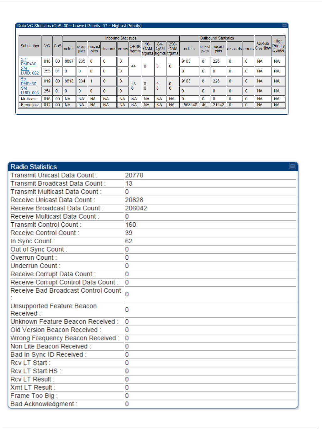
Task 6: Configuring radio parameters PMP 450i and PTP 450i Configuration and User
Guide
Figure 41 Multicast VC statistics
The AP and SM display Transmit and Receive Multicast Data Count (under the Statistics
=> Scheduler tab), as shown in Figure 42.
Figure 42 Multicast scheduler statistics
pmp-0957 (April 2015) 117

PMP 450i and PTP 450i Configuration and User
Task 6: Configuring radio parameters
The frequencies that a user can select are controlled by the country or a region and
the Channel Bandwidth selected. There can be a case where a user adds a custom
frequency (from the Custom Frequency page) and cannot see it in the pull down
menu.
118 pmp-0957 (April 2015)

Task 6: Configuring radio parameters PMP 450i and PTP 450i Configuration and User
Guide
pmp-0957 (April 2015) 119
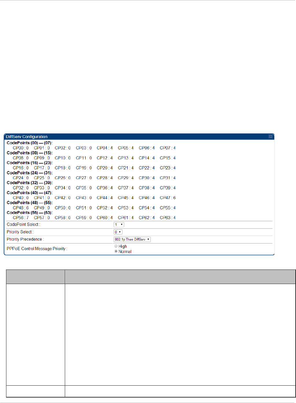
PMP 450i and PTP 450i Configuration and User
Task 6: Configuring radio parameters
IPv6 Prioritization
System Release 13.2 provides operators the ability to prioritize IPv6 traffic in addition
to IPv4 traffic. IPv6 prioritization works similar to IPv4 prioritization where the user
can select the Code Point and the corresponding priority from the GUI of the AP and
the IPv6 packet is set up accordingly. There is no separate GUI option for IPv6 priority.
Once the priority is set, it is set for IPv4 and IPv6 packets. Then depending upon which
packet is received, the set priority is used. The default for IPv6 priority is none.
Configuring IPV6 Priority
IPv6 prioritization is set using the DiffServ tab on the AP and SM (located at
Configuration => DiffServ). A priority set to a specific Code Point will apply to both
IPv4 and IPv6 traffic.
Figure 43 DiffServ tab on AP and SM
Table 35 DiffServ attributes
Attribute Meaning
CodePoint 1
through
CodePoint
47
CodePoint
49 through
CodePoint
55
CodePoint
57 through
Priorities of 0 through 3 map to the low-priority channel; 4 through 7 to
the high- priority channel. The mappings are the same as 802.1p VLAN
priorities.
Consistent with RFC 2474
CodePoint 0 is predefined to a fixed priority
value of 0 (low-priority channel).
CodePoint 48 is predefined to a fixed priority value of 6 (high-priority
channel). CodePoint 56 is predefined to a fixed priority value of 7 (high-
priority channel).
Operator cannot change any of these three fixed priority values. Among
the settable parameters, the priority values (and therefore the handling
f k t i th hi h l i it h l) t i th AP f ll
CodePoint Select This represents the CodePoint Selection to be modified via Priority Select
120 pmp-0957 (April 2015)

Task 6: Configuring radio parameters PMP 450i and PTP 450i Configuration and User
Guide
Priority Select The priority setting input for the CodePoint selected in CodePoint Select
Priority
Precedence
Allows operator to decide if 802.1p or DiffServ priority bits must be
used first when making priority decisions.
PPPoE
Control
Message
Priority
Operators may configure the AP to utilize the high priority channel for
PPPoE control messages. Configuring the AP in this fashion can
benefit the continuity of PPPoE connections when there are issues
with PPPoE sessions being dropped in the network. This prioritization
may be configured in the DiffServ tab in the Configuration menu of the
AP.
Table 36 DiffServ SNMP objects
Name OID MIB Access Syntax / Description
codePoint0,
codePoint4
8,
codePoint5
6
.1.3.6.1.4.1.161.19.3
.3.9.1,
.1.3.6.1.4.1.161.19.3
.3.9.49,
.1.3.6.1.4.1.161.19.3
.3.9.57
WHISP-
BOX-
MIBV2-
MIB
read-only INTEGER
codePoint1 through
codePoint47,
codePoint49
through
codePoint55,
codePoint5
.1.3.6.1.4.1.161.19.3
.3.9.2 through
.1.3.6.1.4.1.161.19.3
.3.9.48,
.1.3.6.1.4.1.161.19.3
.3.9.50 through
WHISP-
BOX-
MIBV2-
MIB
read-
write
INTEGER
priorityPrec
endence
.1.3.6.1.4.1.161.19.3
.3.2.122
WHISP-
BOX-
MIBV2-
MIB
read-
write
INTEGER
{eight021pThenDiffServ(
0),
diffser ThenEight021p(1
pppoeCtlPri
ority
.1.3.6.1.4.1.161.19.3
.3.2.149.0
WHISP-
BOX-
MIBV2-
read-
write
INTEGER {normal(0),
high(1)}
pmp-0957 (April 2015) 121
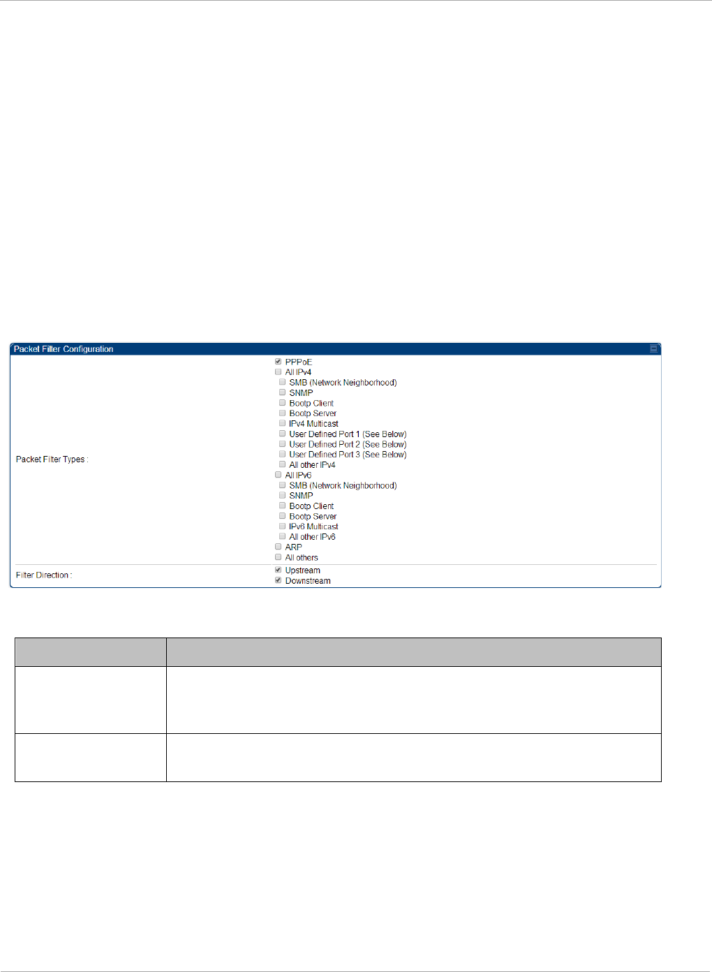
PMP 450i and PTP 450i Configuration and User
Task 6: Configuring radio parameters
IPv6 Filtering
In releases prior to System Release 13.2, the operator can filter (block) specified IPv4
protocols and ports from leaving the AP and SM and entering the network. This protects
the network from both intended and inadvertent packet loading or probing by network
users. By keeping the specified protocols or ports off the network, this feature also
provides a level of protection to users from each other. In System Release 13.2, filtering
capabilities have been added for IPv6 traffic. Unlike IPv6 Prioritization, IPv6 filtering is
done independent of IPv4 filtering.
Configuring IPV6 Filtering
IPv6 filters are set using the Protocol Filtering tab on the AP and SM (at Configuration
=> Protocol Filtering). Once a filter is set for a packet type, those packets will not be
sent over the RF interface depending on “Filter Direction” setting.
Figure 44 Protocol filtering tab on AP and SM (Packet Filter Configuration section)
Table 37 Packet Filter Configuration attributes (IPv6 only)
Attribute Meaning
Packet Filter Types For any box selected, the Protocol Filtering feature blocks the
a
ssociated protocol type. Port filtering on User Defined Ports is
not available for IPv6 at this time.
Filter Direction Operators may choose to filter upstream (uplink) RF packets or
downstream (downlink) RF packets.
122 pmp-0957 (April 2015)

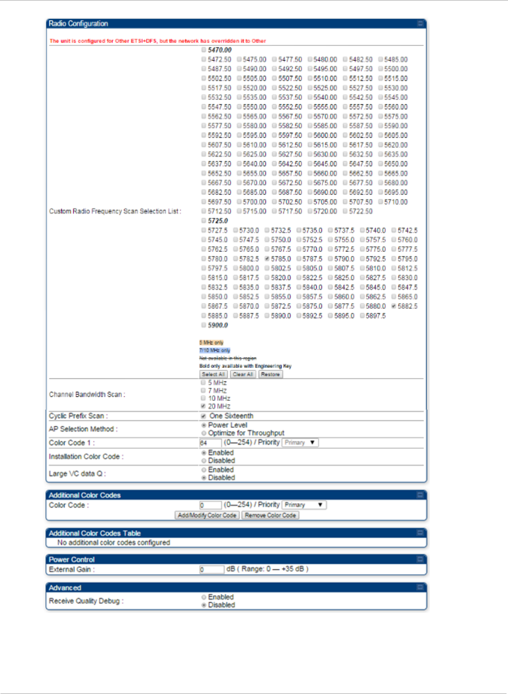
PMP 450i and PTP 450i Configuration and User
Task 6: Configuring radio parameters
124 pmp-0957 (April 2015)

Task 6: Configuring radio parameters PMP 450i and PTP 450i Configuration and User
Guide
In the Radio tab of the SM, you may set the following parameters.
Table 38 SM Radio attributes
Attribute Meaning
Custom Radio
Frequency Scan
Selection List
Check any frequency that you want the SM to scan for AP
transmissions.
Prior to System Release 12.0.3, the PMP 450i SM boot sequence
included loading the current channel bandwidth (10 MHz or 20
MHz, but not both) and frequency band and scanning selected
frequencies in the respective frequency band. After a scan of all
the selected frequencies, the SM can attempt to register to the
best AP based on the SM’s current configuration.
With the introduction of the Full Spectrum Band Scan feature in
12.0.3, SMs first boot into the smallest selected channel
bandwidth (10 MHz, if selected) and scan all selected frequencies
across the 5.7 GHz frequency bands.
After this scan, if a wider channel bandwidth is selected (20 MHz),
the SM automatically changes to 20 MHz channel bandwidth and
then scans for APs. After the SM finishes this final scan it will
evaluate the best AP with which to register. If required for
registration, the SM changes its channel bandwidth back to 10
MHz to match the best AP.
The SM will attempt to connect to an AP based on power level
(which affects the modulation state), channel bandwidth (which
affects throughput) and number of SM registrations to the AP
(which affects system contention performance).
If it is desired to prioritize a certain AP over other available APs,
operators may use the Color Code Priority feature on the SM.
Utilization of the Color Code feature on the AP is recommended to
further constrain the SM’s AP selection.
If the SM does not find any suitable APs for registration after
scanning all channel bandwidths, the SM restarts the scanning
process beginning with the smallest configured channel
bandwidth.
By default, System Release 12.0.3 SMs are configured to scan all
available frequencies and all available channel bandwidths. This
allows operators to install SMs and allow them to register with no
pre-configuration or staging required. SMs upgraded from a
previous release to 12.0.3 retain frequency and channel
bandwidth configuration.
Selecting multiple frequencies and multiple channel bandwidths
impacts the SM scanning time. The biggest consumption of time is
in the changing of the SM channel bandwidth setting.
pmp-0957 (April 2015) 125

PMP 450i and PTP 450i Configuration and User
Task 6: Configuring radio parameters
Attribute Meaning
Continue... The worst case scanning time is approximately two minutes after
boot up (SM with all frequencies and channel bandwidths selected
and registering to an AP at 10 MHz). If only one channel
bandwidth is selected the time to scan all the available
frequencies and register to an AP is approximately one minute
after boot up.
Other scanning features such as Color Code, Installation Color
Code, and RADIUS authentication are unaffected by the Full Band
Scan feature.
Channel Bandwidth
Scan
The channel size used by the radio for RF transmission.
Selecting multiple channel bandwidths will increase
registration and re-registration times.
Cyclic Prefix Scan The cyclic prefix for which AP scanning is executed.
AP Selection
Method
Operators may configure the method by which a scanning SM
selects an AP. By default, AP Selection Method is set to “Optimize
for Throughput”, which has been the mode of operation in
releases prior to 12.0.3.1.
Power Level: AP selection based solely on power level
or
Optimize for Throughput: AP selection based on throughput
optimization – the selection decision is based on power level
(which affects the modulation state), channel bandwidth (which
affects throughput) and number of SM registrations to the AP
(which affects system contention performance).
126 pmp-0957 (April 2015)

Task 6: Configuring radio parameters PMP 450i and PTP 450i Configuration and User
Guide
Attribute Meaning
Color Code 1 to 20 Color code allows you to force the SM to register to only a specific
AP, even where the SM can communicate with multiple APs. For
registration to occur, the color code of the SM and the AP
must
match. Specify a value from 0 to 254.
Color code is not a security feature. Instead, color code is a
management feature, typically for assigning each sector a
different color code. The default setting for the color code value is
0. This value matches only the color code of 0 (
not
all 255 color
codes).
SMs may be configured with up to 20 color codes. These color
codes can be tagged as Primary, Secondary, or Tertiary, or
Disable. When the SM is scanning for APs, it will first attempt to
register to an AP that matches one of the SM’s primary color
codes. Failing that, the SM will continue scanning and attempt to
register to an AP that matches one of the SM’s secondary color
codes. Failing that, the SM will continue scanning and attempt to
register to an AP that matches one of the SM’s tertiary color
codes. This is all done in the scanning mode of the SM and will
repeat until a registration has occurred.
Color codes in the same priority group are treated equally. For
example, all APs matching one of the SM’s primary color codes
are analyzed equally. Likewise, this evaluation is done for the
secondary and tertiary groups in order. The analysis for selecting
an AP within a priority group is based on various inputs, including
signal strength and number of SMs already registered to each AP.
The first color code in the configuration is the pre-Release 9.5
color code. Thus, it is always a primary color code for legacy
reasons.
The color codes can be disabled, with the exception of the first
color code.
Installation Color
Code
With this feature enabled on the AP and SM, operators may install
and remotely configure SMs without having to configure matching
color codes between the modules. When using the Installation
Color Code feature, ensure that the SM is configured with the
factory default Color Code configuration (Color Code 1 is “0”,
Color Code 2-10 set to “0” and “Disable”). The status of the
Installation Color Code can be viewed on the AP Eval web GUI
page, and when the SM is registered using the Installation Color
Code the message “SM is registered via ICC – Bridging Disabled!”
is displayed in red on every SM GUI page. The Installation Color
Code parameter is configurable without a radio reboot for both
the AP and SM.
pmp-0957 (April 2015) 127

PMP 450i and PTP 450i Configuration and User
Task 6: Configuring radio parameters
Attribute Meaning
External Gain This value represents the amount of gain added externally to the
radio in the form of a LENS or Dish. With a CSM, this value
represents the gain of the external antenna that the radio is being
connected to since there is no internal gain for that radio type.
Module Type Recommended
Setting
OFDM integrated antenna with
LENS (5GHz SM only) 5
OFDM Integrated antenna with
CLIP (5GHz SM only) 8
OFDM integrated antenna with
reflector dish 14 (5 GHz)
OFDM Connectorized SM (CSM)
with an external antenna
This value must
correspond to the
published gain of the
external antenna being
used to ensure the
radio meets the
regulatory
requirements in the
region that it is being
deployed in.
Large VC data
Queue
AP and BH have a configurable option used to prevent packet loss
in the uplink due to bursting IP traffic. This is designed for IP
burst traffic particular to video surveillance applications.
Receive Quality
Debug
To aid in link performance monitoring, the AP and SM now report
the number of fragments received per modulation (i.e. QPSK, 16-
QAM, 64-QAM) and per channel (polarization).
Due to CPU load, this will slightly degrade packet per second
processing.
128 pmp-0957 (April 2015)

Task 6: Configuring radio parameters PMP 450i and PTP 450i Configuration and User
Guide
pmp-0957 (April 2015) 129

PMP 450i and PTP 450i Configuration and User
Task 6: Configuring radio parameters
MIMO-A mode of operation for PMP 450i
In releases prior to System Release 13.2, PMP 450i supports MIMO-B mode using the
following modulation levels: QPSK, 16-QAM, 64-QAM and 256-QAM. System Release
13.2 introduces MIMO-A mode of operation using the same modulation levels as the
MIMO-B mode. With MIMO-B, the PMP 450i radio sends different streams of data over
the two antennas whereas with MIMO-A, the PMP 450i radio uses a scheme that tries
to optimize coverage by transmitting the same data over both antennas. This
redundancy improves the signal to noise ratio at the receiver making it more robust, at
the cost of throughput.
In addition to introducing MIMO-A modes, improvements have been made to the existing
rate adapt algorithm to switch between MIMO-A and MIMO-B seamlessly without any
intervention or added configuration by the operator. The various modulation levels used by
the PMP 450i are shown in Table 39.
Table 39 PMP 450i Modulation levels
Rate MIMO-B MIMO-A SISO (for PMP 430
interoperability)
QPSK 2X MIMO-B 1X MIMO-A 1X SISO
16-QAM 4X MIMO-B 2X MIMO-A 2X SISO
64-QAM 6X MIMO-B 3X MIMO-A 3X SISO
265-QAM 8X MIMO-B 4X MIMO-A
For System Performance details of all the PMP 450i products please refer the Link Capacity
Planner v11 at: https://support.cambiumnetworks.com/files/PMP450i.
Table 40 Co-channel Interference per (CCI) MCS, PMP/PTP 450i
MCS of Victim MCS of Interferer Channel BW CCI
1X (QPSK SISO) 6X (64-QAM MIMO-B) 5, 7, 10 or 20 MHz 10 dB
2X (16-QAM SISO) 6X (64-QAM MIMO-B) 5, 7, 10 or 20 MHz 17 dB
3X (64-QAM SISO) 6X (64-QAM MIMO-B) 5, 7, 10 or 20 MHz 25 dB
1X (QPSK MIMO-A) 6X (64-QAM MIMO-B) 5, 7, 10 or 20 MHz 7 dB
2X (16-QAM MIMO-A) 6X (64-QAM MIMO-B) 5, 7, 10 or 20 MHz 14 dB
3X (64-QAM MIMO-A) 6X (64-QAM MIMO-B) 5, 7, 10 or 20 MHz 22 dB
4X (256-QAM MIMO-A)
6X (64-QAM MIMO-B) 5, 7, 10 or 20 MHz 30 dB
2X (QPSK MIMO-B) 6X (64-QAM MIMO-B) 5, 7, 10 or 20 MHz 10 dB
4X (16-QAM MIMO-B) 6X (64-QAM MIMO-B) 5, 7, 10 or 20 MHz 17 dB
6X (64-QAM MIMO-B) 6X (64-QAM MIMO-B) 5, 7, 10 or 20 MHz 25 dB
8X (256-QAM MIMO-B)
6X (64-QAM MIMO-B) 5, 7, 10 or 20 MHz 33 dB
130 pmp-0957 (April 2015)

Task 6: Configuring radio parameters PMP 450i and PTP 450i Configuration and User
Guide
Table 41 Adjacent Channel Interference (ACI) per MCS, PMP/PTP 450i
MCS of Victim MCS of Interferer Channel BW ACI Guard
Band
1X (QPSK SISO) 6X (64-QAM MIMO-B) 5, 7, 10 or 20 MHz -16 dB None
2X (16-QAM SISO) 6X (64-QAM MIMO-B) 5, 7, 10 or 20 MHz -16 dB None
3X (64-QAM SISO) 6X (64-QAM MIMO-B) 5, 7, 10 or 20 MHz -16 dB None
1X (QPSK MIMO-A)
6X (64-QAM MIMO-B) 5, 7, 10 or 20 MHz -13 dB None
2X (16-QAM MIMO-
A)
6X (64-QAM MIMO-B) 5, 7, 10 or 20 MHz -13 dB None
3X (64-QAM MIMO-
A)
6X (64-QAM MIMO-B) 5, 7, 10 or 20 MHz -13 dB None
4X (256-QAM MIMO-
A)
6X (64-QAM MIMO-B) 5, 7, 10 or 20 MHz -10 dB None
2X (QPSK MIMO-B)
6X (64-QAM MIMO-B) 5, 7, 10 or 20 MHz -16 dB None
4X (16-QAM MIMO-
B)
6X (64-QAM MIMO-B) 5, 7, 10 or 20 MHz -16 dB None
6X (64-QAM MIMO-
B)
6X (64-QAM MIMO-B) 5, 7, 10 or 20 MHz -16 dB None
8X (256-QAM MIMO-
B)
6X (64-QAM MIMO-B) 5, 7, 10 or 20 MHz -10 dB None
No Guard Bands are needed for the 5.8 GHz bands.
pmp-0957 (April 2015) 131
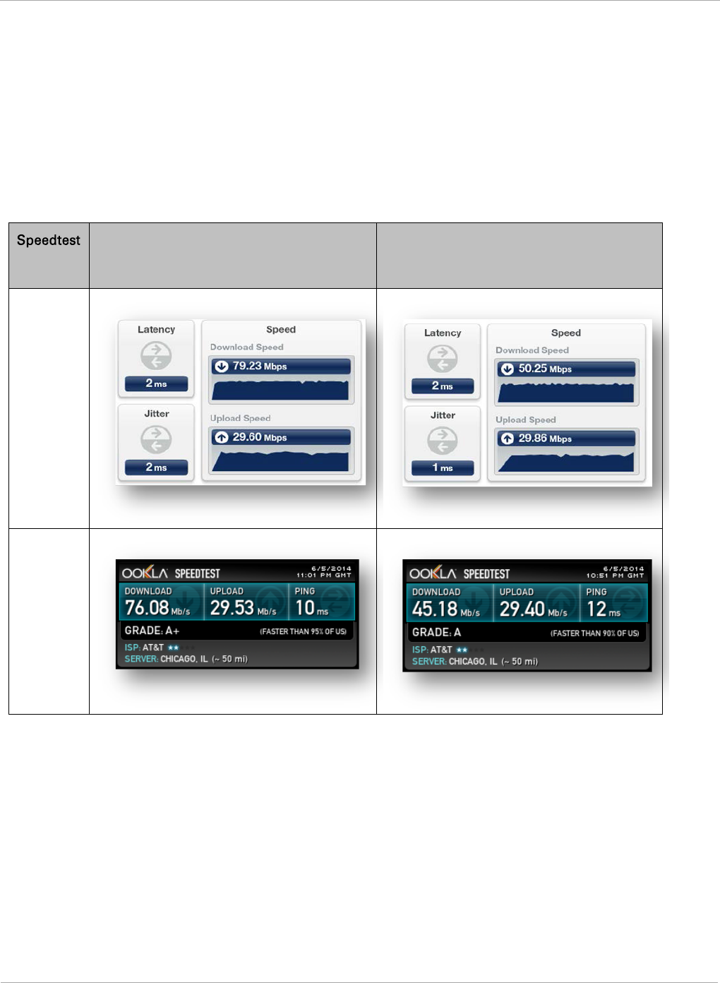
PMP 450i and PTP 450i Configuration and User
Task 6: Configuring radio parameters
Improved PPS performance of PMP 450i SMs
The PMP 450i provides improved packets per second (PPS) performance of the PMP
450i SMs. Through software enhancements and algorithm efficiencies, the PPS
performance of the PMP 450i SM has been improved to 14000 packets/seconds,
measured through a standard RFC2544 test using 64 bytes packets. With this
enhancement, operators are able to provide higher bandwidth including better VoIP
and video services to end customers using existing SM deployments.
Figure 46 Speedtest results example with 1 AP and 1 SM
Server
Bridge Mode
NAT mode
Internal
External
132 pmp-0957 (April 2015)

Task 6: Configuring radio parameters PMP 450i and PTP 450i Configuration and User
Guide
pmp-0957 (April 2015) 133

PMP 450i and PTP 450i Configuration and User
Task 7: Setting up SNMP agent
Task 7: Setting up SNMP agent
Operators may use SNMP commands to set configuration parameters and retrieve data
from the AP and SM modules. Also, if enabled, when an event occurs, the SNMP agent on
the PMP 450i sends a trap to whatever SNMP trap receivers have been configured.
134 pmp-0957 (April 2015)
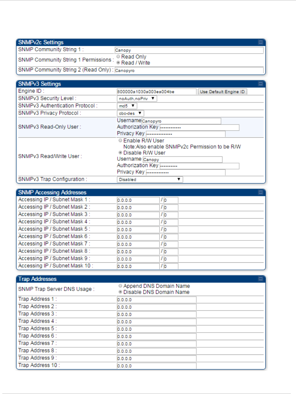
Task 7: Setting up SNMP agent PMP 450i and PTP 450i Configuration and User
Guide
SNMP tab of the AP
Figure 47 SNMP tab of the AP
pmp-0957 (April 2015) 135
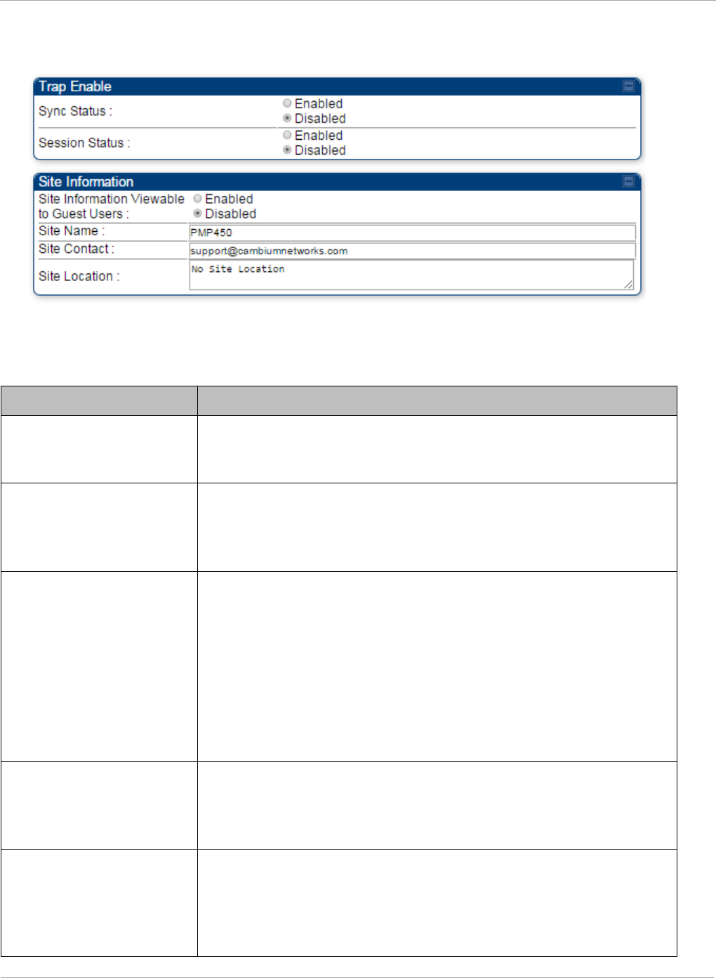
PMP 450i and PTP 450i Configuration and User
Task 7: Setting up SNMP agent
Continue…
You may set the SNMP tab parameters as follows.
Table 42 AP SNMP attributes
Attribute Meaning
SNMP Community String
1
Specify a control string that can allow a Network Management
Station (NMS) to access SNMP information. No spaces are
allowed in this string. The default string is Canopy.
SNMP Community String
1 Permissions
You can designate the SNMP Community String 1 to be the
password for WM, for example, to have Read / Write access to
the module via SNMP or for all SNMP access to the module to
be Read Only.
SNMP Community String
2 (Read Only)
Specify an additional control string that can allow a Network
Management Station (NMS) to read SNMP information. No
spaces are allowed in this string. The default string is
Canopyro. This password will never authenticate a user or an
NMS to read/write access.
The Community String value is clear text and is readable by a
packet monitor. Additional security derives from the
configuration of the Accessing Subnet, Trap Address, and
Permission parameters.
Engine ID The Engine ID may be between 5 and 32 hex characters. The
hex character input is driven by RFC 3411 recommendations on
the Engine ID. The default Engine ID is the MAC address of the
device
SNMPv3 Security Level Specify security model where users are defined and
authenticated before granting access to any SNMP service.
Each device can configure the security level of SNMPv3 to No
authentication/No privacy, Authentication/No privacy, or
Authentication/Privacy.
136 pmp-0957 (April 2015)

Task 7: Setting up SNMP agent PMP 450i and PTP 450i Configuration and User
Guide
Attribute Meaning
SNMPv3 Authentication
Protocol
Currently, the SNMPv3 authentication protocol MD5 is
supported.
SNMPv3 Privacy
Protocol
Currently, the SNMPv3 privacy protocol CBC-DES is supported.
SNMPv3 Read-Only User This filed allows for a read-only user per devices. The default
values for the Read-Only users is:
• Username = Canopyro
• Authentication Password = authCanopyro
• Privacy Password = privacyCanopyro
SNMPv3 Read/Write
User
Read-write user by default is disabled. The default values for the
Read/Write users is :
• Username = Canopy
• Authentication Password = authCanopy
• Privacy Password = privacyCanopy
SNMPv3 Trap
Configuration
When enabling transmission of SNMPv3 traps the read-only or
read-write user credentials must be used and selected properly
in order for the SNMP manager to correctly interpret the traps.
By default transmission of SNMPv3 traps is disabled and all
traps sent from the radios are in SNMPv2c format.
Accessing IP / Subnet
Mask
1 to 10
Specify the addresses that are allowed to send SNMP requests
to this AP. The NMS has an address that is among these
addresses (this subnet). You must enter both
• The network IP address in the form xxx.xxx.xxx.xxx
• The CIDR (Classless Interdomain Routing) prefix length in
the form /xx
For example:
• the /16 in 198.32.0.0/16 specifies a subnet mask of
255.255.0.0 (the first 16 bits in the address range are
identical among all members of the subnet).
• 192.168.102.0 specifies that any device whose IP address is
in the range 192.168.102.0 to 192.168.102.254 can send
SNMP requests to the AP, presuming that the device
supplies the correct Community String value.
The default treatment is to allow all networks access. For more
information on CIDR, execute an Internet search on “Classless
Interdomain Routing.” You are allowed to specify as many as 10
different accessing IP address, subnet mask combinations.
pmp-0957 (April 2015) 137

PMP 450i and PTP 450i Configuration and User
Task 7: Setting up SNMP agent
Attribute Meaning
SNMP Trap Server DNS
Usage
The management DNS domain name may be toggled such that
the name of the trap server only needs to be specified and the
DNS domain name is automatically appended to that name. The
default SNMP trap server addresses for all 10 available servers
is 0.0.0.0 with the appending of the DNS domain name disabled.
Trap Address
1 to 10
Specify ten or fewer IP addresses (xxx.xxx.xxx.xxx) or DNS
names to which SNMP traps must be sent. Traps inform
Wireless Manager or an NMS that something has occurred. For
example, trap information is sent
• after a reboot of the module.
• when an NMS attempts to access agent information but
either
• supplied an inappropriate community string or SNMP
version number.
• is associated with a subnet to which access is disallowed.
Trap Enable, Sync Status
If you want sync status traps (sync lost and sync regained) sent
to Wireless Manager or an NMS, select Enabled. If you want
these traps suppressed, select Disabled.
Trap Enable, Session
Status
If you want session status traps sent to Wireless Manager or an
NMS, select Enabled.
Site Information
Viewable to Guest Users
Operators can enable or disable site information from appearing
when a user is in GUEST account mode.
Site Name Specify a string to associate with the physical module. This
parameter is written into the
sysName
SNMP MIB-II object and
can be polled by Wireless Manager or an NMS. The buffer size
for this field is 128 characters.
Site Contact Enter contact information for the module administrator. This
parameter is written into the
sysContact
SNMP MIB-II object
and can be polled by Wireless Manager or an NMS. The buffer
size for this field is 128 characters.
Site Location Enter information about the physical location of the module.
This parameter is written into the
sysLocation
SNMP MIB-II
object and can be polled by Wireless Manager or an NMS. The
buffer size for this field is 128 characters.
138 pmp-0957 (April 2015)

Task 7: Setting up SNMP agent PMP 450i and PTP 450i Configuration and User
Guide
SNMP tab of the SM
Figure 48 SNMP tab of the SM
pmp-0957 (April 2015) 139
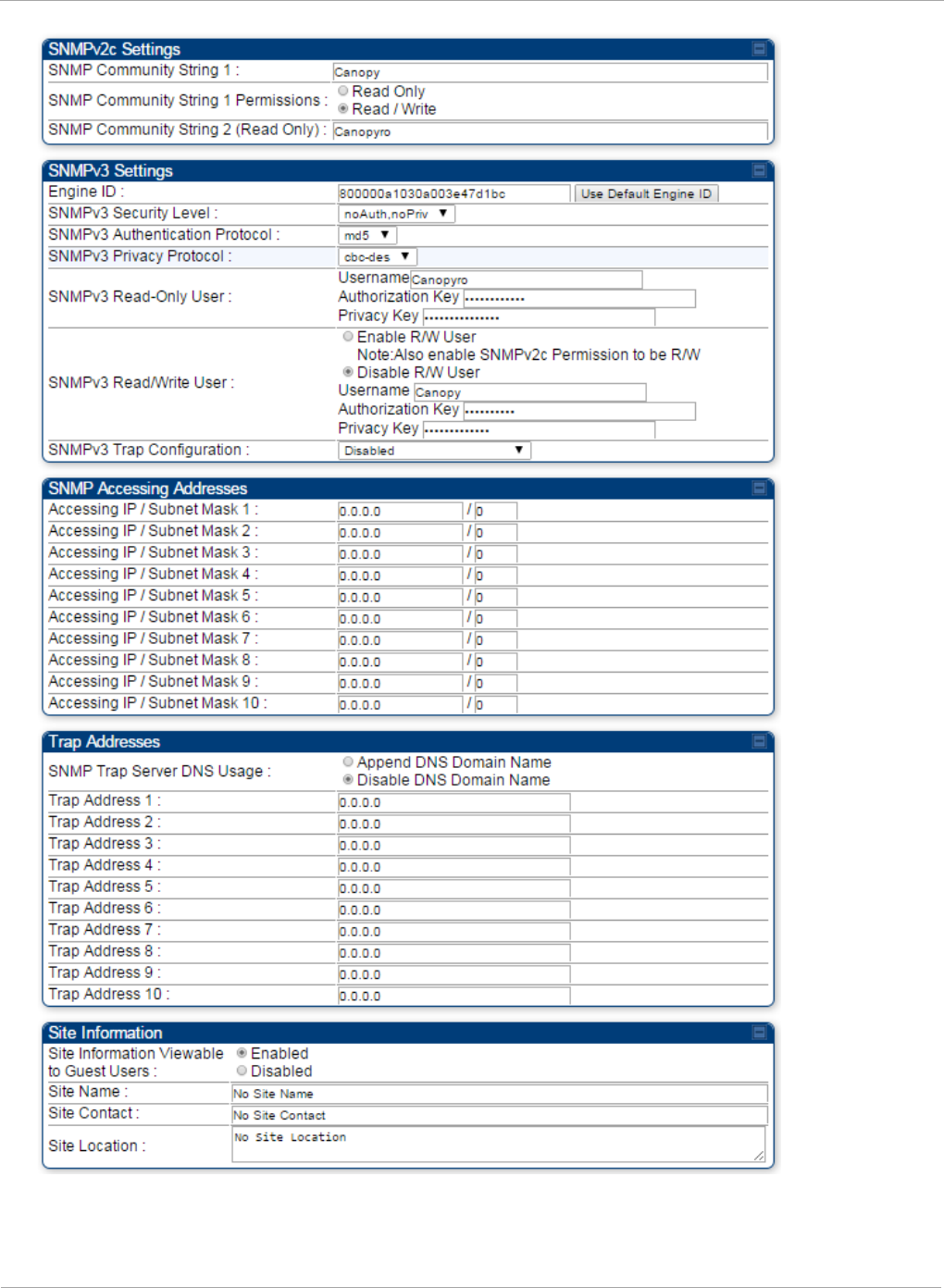
PMP 450i and PTP 450i Configuration and User
Task 7: Setting up SNMP agent
140 pmp-0957 (April 2015)

Task 7: Setting up SNMP agent PMP 450i and PTP 450i Configuration and User
Guide
In the SNMP tab of the SM, you may set the following parameters.
Table 43 SM SNMP attributes
Attribute Meaning
SNMP Community
String 1
Specify a control string that can allow an Network Management
Station (NMS) to access SNMP information. No spaces are
allowed in this string. The default string is Canopy.
SNMP Community
String 1 Permissions
You can designate the SNMP Community String 1 to be the
password for WM, for example, to have Read / Write access to
the module via SNMP or for all SNMP access to the module to be
Read Only.
SNMP Community
String 2 (Read Only)
Specify an additional control string that can allow an Network
Management Station (NMS) to read SNMP information. No spaces
are allowed in this string. The default string is Canopy2. This
password will never authenticate a user or an NMS to read/write
access.
The Community String value is clear text and is readable by a
packet monitor. Additional security derives from the configuration
of the Accessing Subnet, Trap Address and Permission
parameters.
Engine ID The Engine ID may be between 5 and 32 hex characters. The hex
character input is driven by RFC 3411 recommendations on the
Engine ID. The default Engine ID is the MAC address of the device
SNMPv3 Security
Level
Specify security model where users are defined and authenticated
before granting access to any SNMP service. Each device can
configure the security level of SNMPv3 to No authentication/No
privacy, Authentication/No privacy, or Authentication/Privacy.
SNMPv3
Authentication
Protocol
Currently, the SNMPv3 authentication protocol MD5 is
supported.
SNMPv3 Privacy
Protocol
Currently, the SNMPv3 privacy protocol CBC-DES is supported.
SNMPv3 Read-Only
User
This filed allows for a read-only user per devices. The default
values for the Read-Only users is:
• Username = Canopyro
• Authentication Password = authCanopyro
• Privacy Password = privacyCanopyro
pmp-0957 (April 2015) 141

PMP 450i and PTP 450i Configuration and User
Task 7: Setting up SNMP agent
Attribute Meaning
SNMPv3 Read/Write
User
Read-write user by default is disabled. The default values for the
Read/Write users is :
• Username = Canopy
• Authentication Password = authCanopy
• Privacy Password = privacyCanopy
SNMPv3 Trap
Configuration
When enabling transmission of SNMPv3 traps the read-only or
read-write user credentials must be used and selected properly in
order for the SNMP manager to correctly interpret the traps. By
default transmission of SNMPv3 traps is disabled and all traps
sent from the radios are in SNMPv2c format.
Accessing IP / Subnet
Mask
1 to 10
Specify the addresses that are allowed to send SNMP requests to
this SM. Wireless Manager or the NMS has an address that is
among these addresses (this subnet). You must enter both
The network IP address in the form xxx.xxx.xxx.xxx
The CIDR (Classless Interdomain Routing) prefix length in the
form /xx
For example
• the /16 in 198.32.0.0/16 specifies a subnet mask of 255.255.0.0
(the first 16 bits in the address range are identical among all
members of the subnet).
• 192.168.102.0 specifies any device whose IP address is in the
range 192.168.102.0 to 192.168.102.254 can send SNMP
requests to the SM, presuming that the device supplies the
correct Community String value.
The default treatment is to allow all networks access (set to 0).
For more information on CIDR, execute an Internet search on
“Classless Interdomain Routing.” You are allowed to specify as
many as 10 different accessing IP address, subnet mask
combinations.
RECOMMENDATION:
The subscriber can access the SM by changing
the subscriber device to the accessing subnet.
This hazard exists because the Community
String and Accessing Subnet are both visible
parameters. To avoid this hazard, configure the
SM to filter (block) SNMP requests.
142 pmp-0957 (April 2015)

Task 7: Setting up SNMP agent PMP 450i and PTP 450i Configuration and User
Guide
Attribute Meaning
SNMP Trap Server
DNS Usage
The management DNS domain name may be toggled such that the
name of the trap server only needs to be specified and the DNS
domain name is automatically appended to that name. The default
SNMP trap server addresses for all 10 available servers is 0.0.0.0
with the appending of the DNS domain name disabled.
Trap Address
1 to 10
Specify ten or fewer IP addresses (xxx.xxx.xxx.xxx) to which trap
information must be sent. Trap information informs Wireless
Manager or an NMS that something has occurred. For example,
trap information is sent
after a reboot of the module.
when Wireless Manager or an NMS attempts to access agent
information but either
supplied an inappropriate community string or SNMP version
number.
is associated with a subnet to which access is disallowed.
Site Information
Viewable to Guest
Users
Operators can enable or disable site information from appearing
when a user is in GUEST account mode.
Site Name Specify a string to associate with the physical module. This
parameter is written into the
sysName
SNMP MIB-II object and
can be polled by Wireless Manager or an NMS. The buffer size for
this field is 128 characters.
Site Contact Enter contact information for the module administrator. This
parameter is written into the
sysContact
SNMP MIB-II object and
can be polled by Wireless Manager or an NMS. The buffer size for
this field is 128 characters.
Site Location
Enter information about the physical location of the module. This
parameter is written into the
sysLocation
SNMP MIB-II object and
can be polled by Wireless Manager or an NMS. The buffer size for
this field is 128 characters.
pmp-0957 (April 2015) 143

PMP 450i and PTP 450i Configuration and User
Task 8: Configuring syslog
Task 8: Configuring syslog
System Release 13.0 includes enhancements to the existing Syslog functionality. Additional
events are now logged as explained in Table 44.
Table 44 Syslog enhancements
Syslog enhancement Description
Timestamp All syslog messages captured from the radio have a
timestamp.
Configuration Changes
This includes any device setting that has changed and
includes the old or new parameter value, including the
device reboots.
User Login and Logout Syslog records each user login and logout, with
username.
Add or Delete of user accounts
through GUI and SNMP
Syslog captures any user accounts that are added or
deleted.
Spectrum Analysis Syslog records a message every time Spectrum
Analysis runs.
Since the AP must be set to a SM for Spectrum
Analysis, syslog messages is not be reported from the
radio until the scan is done and the radio mode is
switched back to AP.
Link Test Syslog records a message every time a Link Test is
run.
Clear Statistics
Syslog sends a message when Statistics are cleared.
This is done individually for each statistics page that is
cleared.
SM Register or De-register Syslog records a message when a SM registers or
deregisters.
144 pmp-0957 (April 2015)
Task 8: Configuring syslog PMP 450i and PTP 450i Configuration and User
Guide
Configuring AP system logging (syslog)
To configure system logging, select the menu option Configuration => Syslog. The
Syslog Configuration page for AP is shown in Figure 49.
Figure 49 AP Syslog Configuration page
Table 45 AP Syslog Configuration attributes
Attribute Meaning
Syslog DNS Server
Usage
To configure the AP to append or not append the DNS server
name to the syslog server name.
Syslog Server The dotted decimal or DNS name of the syslog server address.
Syslog Server Port The syslog server port (default 514) to which syslog messaging
is sent.
AP Syslog Transmit When enabled, syslog messages are sent from the AP.
SM Syslog Transmit When enabled, syslog messages are sent from all the registered
SMs, unless they are individually set to override this.
Syslog Minimum
Level
This provides a selection for the minimum syslog message
severity that is sent to the syslog server. Values range from
fatal (highest severity and least verbose) to info (lowest
severity, maximum verbosity).
For example: If the Syslog Minimum Level is set to notice, then
only messages with severity notice and above are sent.
pmp-0957 (April 2015) 145
PMP 450i and PTP 450i Configuration and User
Task 8: Configuring syslog
Configuring SM system logging (syslog)
To configure system logging, select the menu option Configuration => Syslog. The
Syslog Configuration page is shown in Figure 50.
Syslog only works with SMs that have Network Accessibility set to Public.
Figure 50 SM Syslog Configuration page
Table 46 Syslog Configuration attributes
Attribute Meaning
Syslog
Configuration
Source
This control determines whether the SM will attempt to use the syslog
server definition from the AP, or whether it will use a local server
definition.
• When set to “AP preferred, use local when AP configuration
unavailable”, and if the SM can register with an AP, then it uses the
syslog server defined on that AP. If the SM cannot register then it
will syslog to its locally defined syslog server through its wired
connection, if any.
• When set to “Local only” the SM ignores the AP’s definition of the
syslog server and allows the syslog server to be configured
individually for each SM.
Syslog DNS
Server Usage
To configure the SM to append or not the DNS server name to the
syslog server name.
Syslog Server The dotted decimal or DNS name of the syslog server address.
Syslog Server
Port The syslog server port (default 514) to which syslog messaging is sent.
146 pmp-0957 (April 2015)

Task 8: Configuring syslog PMP 450i and PTP 450i Configuration and User
Guide
Attribute Meaning
Syslog
Transmission
Controls the SMs ability to transmit syslog messages. When set to
“Learn from AP” the AP will control whether this SM transmits syslog
messages. When set to “enable” or “disable” the SM will control
whether it sends syslog messages. This allows an operator to override
the AP settings for individual SMs in a sector.
Syslog Minimum
Level Source
This control determines whether the SM attempts to use the minimum
syslog level defined by the AP, or whether it uses a local defined value
using the “Syslog Minimum Level” parameter.
• When set to “AP preferred, use local when AP configuration
unavailable”, and if the SM can register with an AP, then it uses the
Syslog Minimum Level defined on that AP. If the SM cannot register
then it uses its own Syslog Minimum Level setting.
• When set to “Local only” the SM will always use its own Syslog
Minimum Level setting and ignores the AP’s setting.
Syslog Minimum
Level
This provides a selection for the minimum syslog message severity that
is sent to the syslog server. Values range from fatal (highest severity
and least verbose) to info (lowest severity, maximum verbosity).
For example: If the Syslog Minimum Level is set to notice, then only
messages with severity notice and above are sent.
pmp-0957 (April 2015) 147
PMP 450i and PTP 450i Configuration and User
Task 9: Configuring remote access
Task 9: Configuring remote access
Configuring SM IP over-the-air access
To access the SM management interface from a device situated above the AP, the SM’s
Network Accessibility parameter (under the web GUI at Configuration => IP) may be
set to Public.
Figure 51 SM IP Configuration page
Table 47 SM IP Configuration attributes
Attribute Meaning
IP Address Internet Protocol (IP) address. This address is used by family of Internet
protocols to uniquely identify this unit on a network.
Network
Accessibility
Specify whether the IP address of the SM must be visible to only a device
connected to the SM by Ethernet (Local) or be visible to the AP as well
(Public).
Subnet Mask If Static IP is set as the Connection Type of the WAN interface, then this
parameter configures the subnet mask of the SM for RF management traffic.
Gateway IP
Address
If Static IP is set as the Connection Type of the WAN interface, then this
parameter configures the gateway IP address for the SM for RF management
traffic.
DHCP state
If Enabled is selected, the DHCP server automatically assigns the IP
configuration (IP address, subnet mask, and gateway IP address) and the
values of those individual parameters (above) are not used. The setting of this
DHCP state parameter is also viewable (read only), in the Network Interface
tab of the Home page.
148 pmp-0957 (April 2015)

Task 9: Configuring remote access PMP 450i and PTP 450i Configuration and User
Guide
Attribute Meaning
DNS IP Address
Canopy devices allow for configuration of a preferred and alternate DNS
server IP address either automatically or manually. Devices must set DNS
server IP address manually when DHCP is disabled for the management
interface of the device. The default DNS IP addresses are 0.0.0.0 when
configured manually.
Preferred DNS
Server The first address used for DNS resolution.
Alternate DNS
Server
If the Preferred DNS server cannot be reached, the Alternate DNS Server is
used.
Domain Name
The operator’s management domain name may be configured for DNS. The
domain name configuration can be used for configuration of the servers in the
operator’s network. The default domain name is example.com, and is only
used if configured as such.
Accessing SM over-the-air by LUID
The SM may be accessed via the AP management GUI by navigating to either Home =>
Session Status or Home => Remote Subscribers and clicking on the SM’s hyperlink.
For example, to access one of the SMs, click LUID: 002 – [0a-00-3e-37-b9-fd], as shown
in Figure 52.
pmp-0957 (April 2015) 149
PMP 450i and PTP 450i Configuration and User
Task 9: Configuring remote access
Figure 52 AP Session Status page
The SessionStatus.xml hyper link allows user to export all displayed SM data in Session
Status table into an xml file.
To access any one of the SMs, click PMP450i SM hyperlink, as shown in Figure 53.
Figure 53 AP Remote Subscribers page
150 pmp-0957 (April 2015)
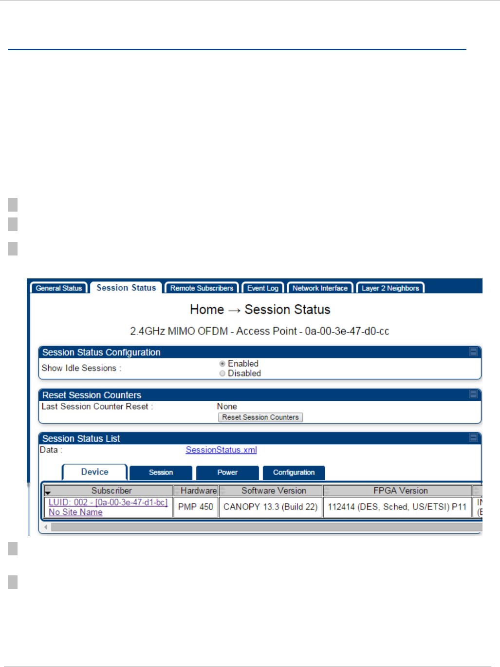
Task 10: Monitoring the AP-SM Link PMP 450i and PTP 450i Configuration and User
Guide
Task 10: Monitoring the AP-SM Link
Monitoring the AP-SM Link
After the SM installer has configured the link, either an operator in the network office
or the SM installer in the field (if read access to the AP is available to the installer) must
perform the following procedure. Who is authorized and able to do this depends on local
operator password policy, management VLAN setup and operational practices.
To monitor the AP-SM link for performance, follow these instructions:
Procedure 11 Monitoring the AP-SM link
1 Access the web interface of the AP
2 In the left-side menu of the AP interface, select Home.
3 Click the Session Status tab.
Figure 54 AP Session Status page
4 The Device tab of Session Status List display all displayed SMs – MAC address, PMP
Hardware, Software Version, FPGA Version and State
5 Click Session Count tab of Session Status List to display values for Session Count, Reg
Count, and Re-Reg Count.
pmp-0957 (April 2015) 151

PMP 450i and PTP 450i Configuration and User
Task 10: Monitoring the AP-SM Link
• Session Count: This field displays how many sessions the SM has had with the AP.
Typically, this is the sum of Reg Count and Re-Reg Count. However, the result of
internal calculation may display here as a value that slightly differs from the sum.
• Reg Count: When a SM makes a registration request, the AP checks its local data to
see whether it considers the SM to be already registered. If the AP concludes that the
SM is not, then the request increments the value of this field.
• Typically, a Re-Reg is the case where both
o SM attempts to reregister for having lost communication with the AP.
o
AP has not yet observed the link to the SM as being down.
6 Click Power tab of Session Status list to display Downlink Rate, AP Tx Power (dBm), Signal
Strength Radio (dB) and Signal to Noise Radio (dB).
7 Click Configuration tab of Session Status list to get QoS configuration details:
• Sustained Data Rate (kbps)
• Burst Allocation (kbit)
• Max Burst Rate (kbit)
• Low Priority CIR (kbps)
7 Briefly monitor these values, occasionally refreshing this page by clicking another tab and
then the Session Status tab again.
7 If these values are low (for example, 1, 1, and 0, respectively, meaning that the SM
registered and started a stable session once) and are not changing:
• Consider the installation successful.
• Monitor these values from the network office over the next several hours and days.
If these values are greater than 1, 1, and 0, or they increase while you are monitoring
them, troubleshoot the link. (For example, Use Receive Power Level for aiming and then
use Link Tests to confirm alignment).
Exporting Session Status page of the AP
The SessionStatus.xml hyper link allows user to export all displayed SM data in
Session Status table into an xml file.
152 pmp-0957 (April 2015)
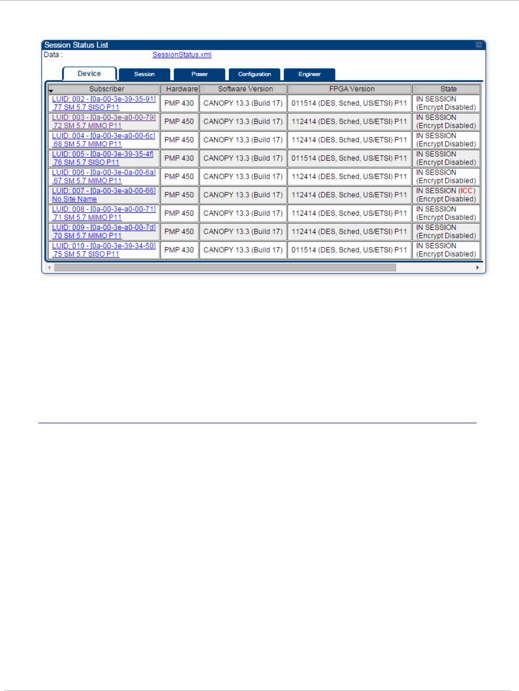
Task 10: Monitoring the AP-SM Link PMP 450i and PTP 450i Configuration and User
Guide
Figure 55 Exporting Session Status page of the AP
In case, the session status page does not list any SM, the SessionStatus.xml will still
be visible but the file would be empty. The file will contain data from all of the 5
different tables.
Export from command line
The scripts users can also get this file from command line, you have to authenticate
successfully in order to download the file.
Wget
http://169.254.1.1/SessionStatus.xml?CanopyUsername=test&CanopyPassword=test
pmp-0957 (April 2015) 153

PMP 450i and PTP 450i Configuration and User
Task 11: Configuring quality of service
Task 11: Configuring quality of service
Maximum Information Rate (MIR) Parameters
Point-to-multipoint links use the following MIR parameters for bandwidth
management:
• Sustained Uplink Data Rate (kbps)
• Uplink Burst Allocation (kb)
• Sustained Downlink Data Rate (kbps)
• Downlink Burst Allocation (kb)
• Max Burst Downlink Data Rate (kbps)
• Max Burst Uplink Data Rate (kbps)
You can independently set each of these parameters per AP or per SM.
Token Bucket Algorithm
The software uses a
token bucket
algorithm that has the following features:
• Stores credits (tokens) for the SM to spend on bandwidth for reception or transmission.
• Drains tokens during reception or transmission.
• Refills with tokens at the sustained rate set by the network operator.
For each token, the SM can send toward the network in the uplink (or the AP can
send toward the SM in the downlink) an equivalent number of kilobits. Two buckets
determine the permitted throughput: one in the SM for uplink and one in the AP for
downlink.
The applicable set of Uplink Burst Allocation and Downlink Burst Allocation
parameters determine the
number
of tokens that can fill each bucket. When the SM
transmits (or the AP transmits) a packet, the equivalent number of tokens is
removed from the uplink (or downlink) bucket.
Except when full, the bucket is continuously being refilled with tokens at
rates
that
the applicable set of Sustained Uplink Data Rate and Sustained Downlink Data
Rate parameters specify. The bucket often drains at a rate that is much faster than
the sustained data rate but can refill at only the sustained data rate. Thus, the
effects of the allocation and rate parameters on packet delay are as follows:
• The burst allocation affects how many kilobits are processed before packet delay is
imposed.
• The sustained data rate affects the packet delay that is imposed.
154 pmp-0957 (April 2015)

Task 11: Configuring quality of service PMP 450i and PTP 450i Configuration and User
Guide
MIR Data Entry Checking
Uplink and downlink MIR is enforced as shown in Figure 56.
In these figures,
entry
refers to the setting in the data rate parameter, not the burst
allocation parameter.
Figure 56 Uplink and downlink rate caps adjusted to apply aggregate cap
For example, in the SM, if you set the Sustained Uplink Data Rate parameter to 2,000
kbps and the Sustained Downlink Data Rate parameter to 10,000 kbps, then the uplink
and downlink MIR that is enforced for the SM can be calculated as shown in Figure 57.
Figure 57 Uplink and downlink rate cap adjustment example
In this example case, the derived 1,167-kbps uplink and 5,833-kbps downlink MIR sum to
the fixed 7,000-kbps aggregate cap of the SM.
Committed Information Rate (CIR)
The Committed Information Rate (CIR) capability feature enables the service provider to
guarantee to any subscriber that bandwidth will never decrease to below a specified
minimum unless CIR is oversubscribed or RF conditions are degraded. CIR is
oversubscribed when there is not enough available bandwidth to support CIR configuration
for all subscribers. In this condition, SMs which are configured with a nonzero CIR will all
operate at the maximum data rate supported by the link (subject to Maximum Information
Rate and Burst Rate/Allocations). SMs which are configured with a CIR of 0 kbps will not
transmit until CIR-configured SMs have completed transmission. CIR may be configured
independently for high priority traffic and for low priority traffic.
CIR parameters may be configured in the following ways:
• Web-based management GUI
• SNMP
• Authentication Server (RADIUS) - when a SM successfully registers and authenticates,
CIR information is retrieved from the RADIUS server.
uplink cap enforced =
uplink entry x aggregate cap for the SM
uplink entry + downlink entry
downlink cap enforced =
downlink entry x aggregate cap for the SM
uplink entry + downlink entry
uplink c ap enforced =
2,000 kbps x 7,000 kbps
2,000 kbps + 10,000 kbps
= 1,167 kbps
downlink cap enforced =
10,000 kbps x 7,000 kbps
2,000 kbps + 10,000 kbps
= 5,833 kbps
pmp-0957 (April 2015) 155

PMP 450i and PTP 450i Configuration and User
Task 11: Configuring quality of service
Active CIR configuration can be verified via the AP’s Home => Session Status tab.
Bandwidth from the SM Perspective
In the SM, normal web browsing, e-mail, small file transfers and short streaming
video are rarely rate limited with practical bandwidth management (QoS) settings.
When the SM processes large downloads such as software upgrades and long
streaming video or a series of medium-size downloads, the bucket rapidly drains,
the burst limit is reached, and some packets are delayed. The subscriber experience
is more affected in cases where the traffic is more latency sensitive.
Interaction of Burst Allocation and Sustained Data Rate
Settings
If the Burst Allocation is set to 1200 kb and the Sustained Data Rate is set to 128
kbps, a data burst of 1000 kb is transmitted at full speed because the Burst
Allocation is set high enough. After the burst, the bucket experiences a significant
refill at the Sustained Data Rate. This configuration uses the advantage of the
settable Burst Allocation.
If both the Burst Allocation and the Sustained Data Rate are set to 128 kb, a burst is
limited to the Burst Allocation value. This configuration does not take advantage of
the settable Burst Allocation.
If the Burst Allocation is set to 128 kb and the Sustained Data Rate is set to 256
kbps, the actual rate is the burst allocation (but in kbps). As above, this
configuration does not take advantage of the settable Burst Allocation.
High-priority Bandwidth
To support low-latency traffic such as VoIP (Voice over IP) or video, the system
implements a high-priority channel. This channel does not affect the inherent
latencies in the system but allows high-priority traffic to be immediately served. The
high-priority pipe separates low-latency traffic from traffic that is latency tolerant,
such as standard web traffic and file downloads.
The number of channels available on the AP is reduced by the number of SMs
configured for the high-priority channel (each SM operating with high-priority
enabled uses two channels (virtual circuits) instead of one).
A module prioritizes traffic by
• reading the Low Latency bit (Bit 3) in the IPv4 Type of Service (ToS) byte in a received
packet. Bit 3 is set by a device outside the system.
• reading the 802.1p field of the 802.1Q header in a received packet, where VLAN is
enabled on the module.
156 pmp-0957 (April 2015)

Task 11: Configuring quality of service PMP 450i and PTP 450i Configuration and User
Guide
• comparing the 6-bit Differentiated Services Code Point (DSCP) field in the ToS byte of a
received packet to a corresponding value in the Diffserv tab of the Configuration page
of the module. A packet contains no flag that indicates whether the encoding is for the
Low Latency bit or the DSCP field. For this reason, you must ensure that all elements in
your trusted domain, including routers and endpoints, set and read the ToS byte with
the same scheme.
Modules monitor ToS bytes with DSCP fields, but with the following differences:
• The 6-bit length of the field allows it to specify one of 64 service
differentiations.
• These correlate to 64 individual (CodePoint) parameters in the Diffserv tab
of the Configuration page.
• Per RFC 2474, 3 of these 64 are preset and cannot be changed. (See
http://www.faqs.org/rfcs/rfc1902.html.)
• For any or all of the remaining 61 CodePoint parameters, you can specify a
value of
o 0 through 3 for low-priority handling.
o 4 through 7 for high-priority handling.
Ensure that your Differentiated Services domain boundary nodes mark any
entering packet, as needed, so that it specifies the appropriate Code Point for that
traffic and domain. This prevents theft of service level.
An example of the Diffserv tab in the Configuration page and parameter
descriptions are provided under DiffServ tab of the AP on Page 163. This tab and its
rules are identical from module type to module type. However, any of the 61
configurable Code Points can be set to a different value from module to module,
thus defining unique per-hop behavior for some traffic.
This tab in the AP sets the priorities for the various packets in the downstream (sent
from the public network). This tab in the SM sets the priorities for the various
packets in the upstream (sent to the public network).
Typically, some SMs attach to older devices that use the ToS byte as originally
formatted, and others to newer devices that use the DSCP field. The
default
values
in the Diffserv tab allow your modules to prioritize traffic from the older devices
roughly the same as they traditionally have. However, these default values may
result in more high-priority traffic as DSCP fields from the newer devices are read
and handled. So, after making changes in the Diffserv tab, carefully monitor the
high-priority channel for high packet rates
• in SMs that you have identified as those to initially set and watch.
• across your network when you have broadly implemented Code Point values, such as
via SNMP.
pmp-0957 (April 2015) 157
PMP 450i and PTP 450i Configuration and User
Task 11: Configuring quality of service
Traffic Scheduling
The characteristics of traffic scheduling in a sector are summarized in Table 48.
Table 48 Characteristics of traffic scheduling
Category Factor Treatment
Throughput Aggregate throughput, less additional
overhead 120 Mbps
Latency
Number of frames required for the
scheduling process 1
Round-trip latency ≈ 6 ms
AP broadcast the download schedule No
High-
priority
Channel
Allocation for
uplink
high-priority traffic
on amount of high-priority traffic
Dynamic, based on amount of
high-priority traffic
Allocation for
downlink
high-priority
traffic on amount of high-priority traffic
Dynamic, based on amount of
high-priority traffic
Order of transmission
CIR high-priority
CIR low-priority
Other high-priority
Other low-priority
Power requirements affect the recommended maximums for power cord length feeding the
CMMmicro or CMM4. See the dedicated user guide that supports the CMM that you are
deploying. However, the requirements do not affect the maximums for the CMM2.
Packets that have a priority of 4 to 7 in either the DSCP or a VLAN 802.1p tag are
automatically sent on the high-priority channel, but only where the high-priority channel is
enabled.
158 pmp-0957 (April 2015)

Task 11: Configuring quality of service PMP 450i and PTP 450i Configuration and User
Guide
Setting the Configuration Source
The AP includes a Configuration Source parameter, which sets where SMs that
register to the AP are controlled for MIR, CIR, VLAN, and the high-priority channel as
follows. The Configuration Source parameter affects the source of:
• all MIR settings:
o Sustained Uplink Data Rate
o Uplink Burst Allocation
o Max Burst Uplink Data Rate
o Sustained Downlink Data Rate
o Downlink Burst Allocation
o Max Burst Downlink Data Rate
• all CIR settings:
o Low Priority Uplink CIR
o Low Priority Downlink CIR
o Hi Priority Uplink CIR
o Hi Priority Downlink CIR
• all SM VLAN settings
o Dynamic Learning
o Allow Only Tagged Frames
o VLAN Aging Timeout
o Untagged Ingress VID
o Management VID
o VLAN Membership
• the Hi Priority Channel setting
Table 49 Recommended combined settings for typical operations
Most operators
who use…
must set this
parameter…
in this web
page/tab…
in the AP to…
no authentication
server
Authentication
Mode
Configuration/
Security Disabled
Configuration
Source
Configuration/
General SM
Wireless Manager
(Authentication
Server)
Authentication
Mode
Configuration/
Security
Authentication
Server
Configuration
Source
Configuration/
General
Authentication
Server
RADIUS AAA
server
Authentication
Mode
Configuration/
Security RADIUS AAA
Configuration Configuration/ Authentication
pmp-0957 (April 2015) 159

PMP 450i and PTP 450i Configuration and User
Task 11: Configuring quality of service
Most operators
who use…
must set this
parameter…
in this web
page/tab…
in the AP to…
Source General Server
Table 50 Where feature values are obtained for a SM with authentication required
Configuration
Source Setting
in the AP
Values are obtained from
MIR Values VLAN Values
High Priority
Channel
State
CIR Values
Authentication
Server
Authentication
Server
Authentication
Server
Authentication
Server
Authentication
Server
SM SM SM SM SM
Authentication
Server+SM
Authentication
Server
Authentication
Server, then
SM
Authentication
Server, then
SM
Authentication
Server, then
SM
HPC represents the Hi Priority Channel (enable or disable).
Where Authentication Server
, then SM
is the indication, parameters for which
Authentication Server does not send values are obtained from the SM. This is the case
where the Authentication Server server is operating on a Authentication Server release that
did not support the feature. This is also the case where the feature enable/disable flag in
Authentication Server is set to disabled. The values are those previously set or, if none ever
were, then the default values.
Where Authentication Server is the indication, values in the SM are disregarded.
Where
SM
is the indication, values that Authentication Server sends for the SM are
disregarded.
For any SM whose Authentication Mode parameter
is not
set to ‘Authentication
Required’, the listed settings are derived as shown in Table 51.
Table 51 Where feature values are obtained for a SM with authentication disabled
Configuration
Source
Setting
in the AP
Values are obtained from
MIR Values VLAN
Values
High Priority
Channel State
CIR Values
Authentication
Server
AP AP AP AP
SM SM SM SM SM
Authentication
Server+SM
SM SM SM SM
160 pmp-0957 (April 2015)
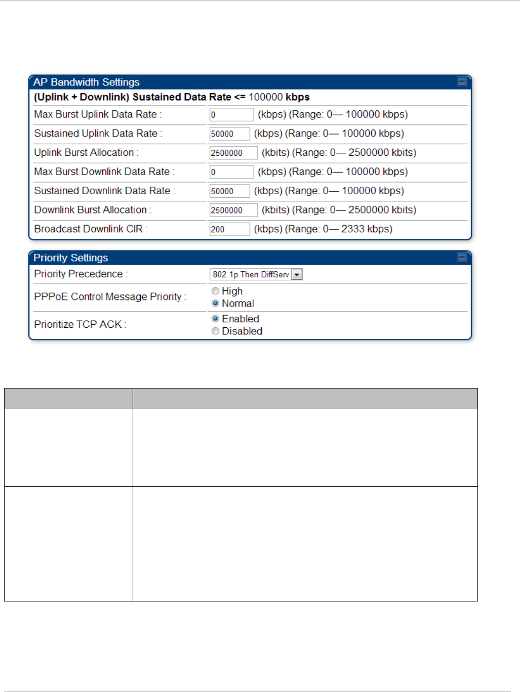
Task 11: Configuring quality of service PMP 450i and PTP 450i Configuration and User
Guide
Quality of Service (QoS) tab of the AP
Figure 58 Quality of Service (QoS) tab of the AP
In the Quality of Service (QoS) tab, you can set AP bandwidth parameters as follows.
Table 52 AP QoS attributes
Attribute Meaning
Max Burst Uplink
Data Rate
These parameters allow operators to specify the data rate at
which a SM is allowed to transmit (until burst allocation limit is
reached) before being recharged at the Sustained Uplink
Data Rate with credits to transit more. When set to 0 (default),
the burst rate is unlimited.
Sustained Uplink Data
Rate
Specify the rate that each SM registered to this AP is
replenished with credits for transmission. This default imposes
no restriction on the uplink. See
• Maximum Information Rate (MIR) Parameters on page 154
• Interaction of Burst Allocation and Sustained Data Rate
Settings on page 156
• Configuration Source on page 62
pmp-0957 (April 2015) 161

PMP 450i and PTP 450i Configuration and User
Task 11: Configuring quality of service
Attribute Meaning
Uplink Burst
Allocation
• Specify the maximum amount of data to allow each SM to
transmit before being recharged at the Sustained Uplink
Data Rate with credits to transmit more. See Maximum
Information Rate (MIR) Parameters on page 154
• Interaction of Burst Allocation and Sustained Data Rate
Settings on page 156
• Configuration Source on page 62
Max Burst Downlink
Data Rate
These parameters allow operators to specify the data rate at
which a SM is allowed to transmit (until burst allocation limit is
reached) before being recharged at the Sustained Downlink
Data Rate with credits to transit more. When set to 0 (default),
the burst rate is unlimited.
Sustained Downlink
Data Rate
• Specify the rate at which the AP is replenished with credits
(tokens) for transmission to each of the SMs in its sector.
This default imposes no restriction on the uplink. See
Maximum Information Rate (MIR) Parameters on page 154
• Interaction of Burst Allocation and Sustained Data Rate
Settings on page 156
• Configuration Source on page 62
Downlink Burst
Allocation
Specify the maximum amount of data to allow the AP to transmit
to any registered SM before the AP is replenished with
transmission credits at the Sustained Downlink Data Rate.
See
• Maximum Information Rate (MIR) Parameters on page 154
• Interaction of Burst Allocation and Sustained Data Rate
Settings on page 156
• Configuration Source on page 62
Broadcast Downlink
CIR
Broadcast Downlink CIR (Committed Information Rate, a
minimum) supports system designs where downlink broadcast is
desired to have higher priority than other traffic. For many
other system designs, especially typical internet access
networks, leave the Broadcast Downlink CIR at the default.
Broadcast Downlink CIR is closely related to the Broadcast
Repeat Count parameter, which is settable in the Radio tab of
the Configuration page in the AP: when the Broadcast Repeat
Count is changed, the total of available bandwidth is also
changed, since packets are being sent one, two, or three times,
according to the setting in the Broadcast Repeat Count
parameter.
Priority Precedence Allows operator to decide if 802.1p or DiffServ priority bits must
be used first when making priority decisions.
162 pmp-0957 (April 2015)
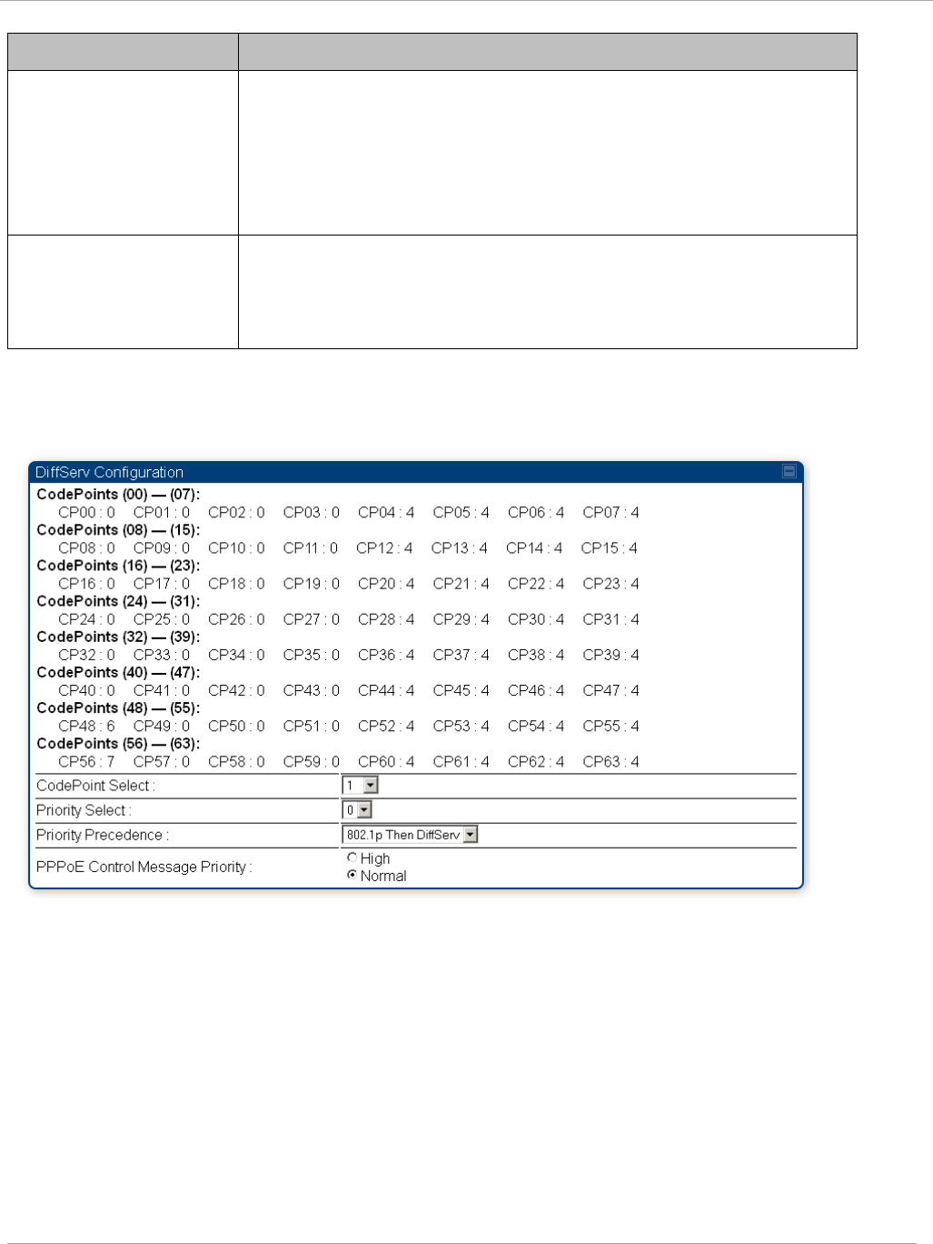
Task 11: Configuring quality of service PMP 450i and PTP 450i Configuration and User
Guide
Attribute Meaning
PPPoE Control
Message Priority
Operators may configure the SM to utilize the high priority
channel for PPPoE control messages. Configuring the SM in this
fashion can benefit the continuity of PPPoE connections when
there are issues with PPPoE sessions being dropped in the
network. This prioritization may be configured in the DiffServ
tab in the Configuration menu of the SM.
Prioritize TCP ACK
To reduce the likelihood of TCP acknowledgement packets being
dropped, set this parameter to Enabled. This can improve
throughput that the end user perceives during transient periods
of congestion on the link that is carrying acknowledgements.
DiffServ tab of the AP
Figure 59 Diffserv tab of the AP
The attributes of Diffserv tab are as follows:
pmp-0957 (April 2015) 163

PMP 450i and PTP 450i Configuration and User
Task 11: Configuring quality of service
Table 53 AP Diffserv attributes
Attribute Meaning
CodePoint 1
through
CodePoint 47
CodePoint 49
through
CodePoint 55
CodePoint 57
through
CodePoint 63
Priorities of 0 through 3 map to the low-priority channel; 4 through 7
to the high-priority channel. The mappings are the same as 802.1p
VLAN priorities.
Consistent with RFC 2474
CodePoint 0 is predefined to a fixed priority value of 0
(low-priority channel).
CodePoint 48 is predefined to a fixed priority value of 6 (high-
priority channel).
CodePoint 56 is predefined to a fixed priority value of 7 (high-
priority channel).
You cannot change any of these three fixed priority values. Among the
settable parameters, the priority values (and therefore the handling of
packets in the high- or low-priority channel) are set in the AP for all
downlinks within the sector and in the SM for each uplink.
CodePoint
Select
This represents the CodePoint Selection to be modified via Priority
Select
Priority Select The priority setting input for the CodePoint selected in CodePoint
Select
Priority
Precedence
Allows operator to decide if 802.1p or DiffServ priority bits must be
used first when making priority decisions.
PPPoE Control
Message
Priority
Operators may configure the AP to utilize the high priority channel
for PPPoE control messages. Configuring the AP in this fashion can
benefit the continuity of PPPoE connections when there are issues
with PPPoE sessions being dropped in the network. This prioritization
may be configured in the DiffServ tab in the Configuration menu of
the AP.
164 pmp-0957 (April 2015)
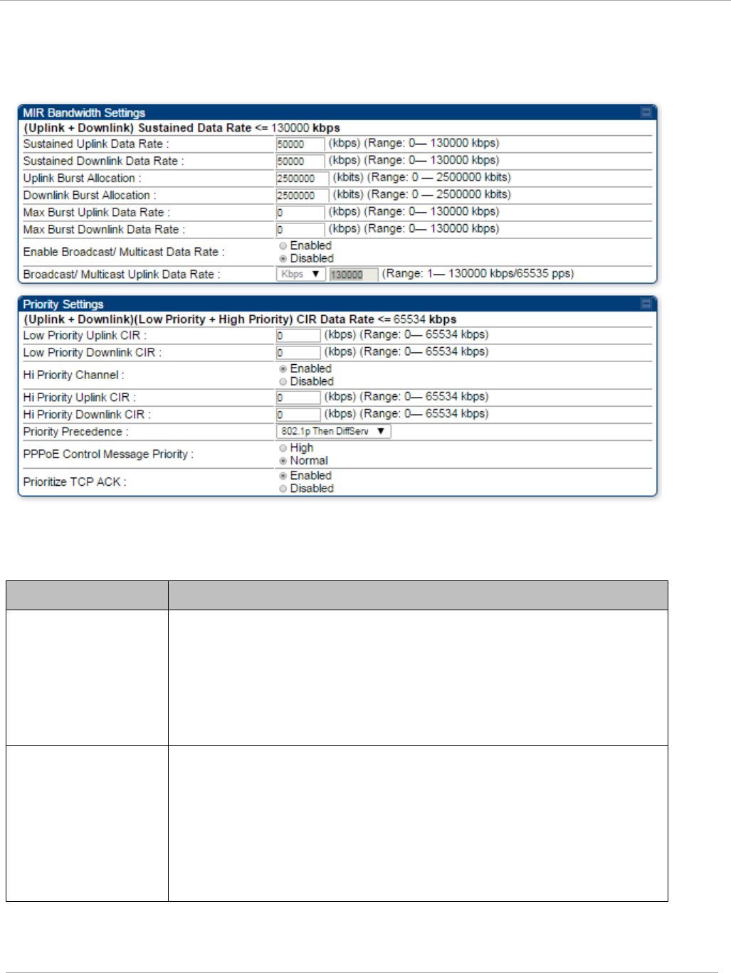
Task 11: Configuring quality of service PMP 450i and PTP 450i Configuration and User
Guide
Quality of Service (QoS) tab of the SM
Figure 60 Quality of Service (QoS) tab of the SM
In the Quality of Service (QoS) tab of the SM, you may set the following parameters.
Table 54 SM Quality of Service attributes
Attribute Meaning
Sustained Uplink
Data Rate
• Specify the rate that this SM is replenished with credits for
transmission. This default imposes no restriction on the uplink.
SeeMaximum Information Rate (MIR) Parameters on page 154
• Interaction of Burst Allocation and Sustained Data Rate
Settings on page 156
• Configuration Source on page 62
Sustained Downlink
Data Rate
• Specify the rate at which the AP is replenished with credits
(tokens) for transmission to this SM. This default imposes no
restriction on the uplink. See Maximum Information Rate
(MIR) Parameters on Page 154
• Interaction of Burst Allocation and Sustained Data Rate
Settings on page 156
• Configuration Source on page 62
pmp-0957 (April 2015) 165

PMP 450i and PTP 450i Configuration and User
Task 11: Configuring quality of service
Attribute Meaning
Uplink Burst
Allocation
• Specify the maximum amount of data to allow this SM to
transmit before being recharged at the Sustained Uplink
Data Rate with credits to transmit more. See Maximum
Information Rate (MIR) Parameters on page 154
• Interaction of Burst Allocation and Sustained Data Rate
Settings on page 156
• Configuration Source on page 62
Downlink Burst
Allocation
• Specify the maximum amount of data to allow the AP to
transmit to this SM before the AP is replenished at the
Sustained Downlink Data Rate with transmission credits.
SeeMaximum Information Rate (MIR) Parameters on page 154
• Interaction of Burst Allocation and Sustained Data Rate
Settings on page 156
• Configuration Source on page 62
Max Burst Uplink
Data Rate
These parameters allow operators to specify the data rate at
which a SM is allowed to transmit (until burst allocation limit is
reached) before being recharged at the Sustained Uplink Data
Rate with credits to transit more. When set to 0 (default), the
burst rate is unlimited.
Max Burst
Downlink Data Rate
These parameters allow operators to specify the data rate at
which a SM is allowed to transmit (until burst allocation limit is
reached) before being recharged at the Sustained Downlink
Data Rate with credits to transit more. When set to 0 (default),
the burst rate is unlimited.
Enable Broadcast /
Multicast Data Rate
This parameter allows the operator to specify if Broadcast and
Multicast data is rate-limited. This data rate can be entered in
Kbps or PPS (Packets Per Second).
Broadcast /
Multicast Data Rate
This parameter allows the operator to specify a data rate at which
Broadcast and Multicast traffic is sent via the radio link.
Low Priority Uplink
CIR
This field indicates the minimum rate at which low priority traffic
is sent over the uplink (unless CIR is oversubscribed or RF link
quality is degraded).
• Committed Information Rate (CIR) on page 155
• Setting the Configuration Source on page 159
Low Priority
Downlink CIR
This field indicates the minimum rate at which low priority traffic
is sent over the downlink (unless CIR is oversubscribed or RF link
quality is degraded).
• Committed Information Rate (CIR) on page 155
• Setting the Configuration Source on page 159
166 pmp-0957 (April 2015)

Task 11: Configuring quality of service PMP 450i and PTP 450i Configuration and User
Guide
Attribute Meaning
Hi Priority Channel
See
• High-priority Bandwidth on page 156
• Configuration Source on page 62
Hi Priority Uplink
CIR
This field indicates the minimum rate at which high priority traffic
is sent over the uplink (unless CIR is oversubscribed or RF link
quality is degraded).
• Committed Information Rate (CIR) on page 155
• Setting the Configuration Source on page 159
Hi Priority
Downlink CIR
This field indicates the minimum rate at which high priority traffic
is sent over the downlink (unless CIR is oversubscribed or RF link
quality is degraded).
• Committed Information Rate (CIR) on page 155
• Setting the Configuration Source on page 159
Priority Precedence Allows operator to decide if 802.1p or DiffServ priority bits must
be used first when making priority decisions.
PPPoE Control
Message Priority
Operators may configure the SM to utilize the high priority
channel for PPPoE control messages. Configuring the SM in this
fashion can benefit the continuity of PPPoE connections when
there are issues with PPPoE sessions being dropped in the
network. This prioritization may be configured in the DiffServ tab
in the Configuration menu of the SM.
Prioritize TCP ACK To reduce the likelihood of TCP acknowledgement packets being
dropped, set this parameter to Enabled. This can improve
throughput that the end user perceives during transient periods of
congestion on the link that is carrying acknowledgements. This
parameter, when enabled, can be particularly useful when
running bi-direction FTP sessions over the link. If a link is
primarily used for video surveillance, it is recommended to
configure this parameter to “Disabled”.
pmp-0957 (April 2015) 167
PMP 450i and PTP 450i Configuration and User
Task 11: Configuring quality of service
DiffServ tab of the SM
Figure 61 DiffServ tab of the SM
In the DiffServ tab of the SM, you may set the following parameters.
Table 55 SM DiffServ attributes
Attribute Meaning
CodePoint 1
through
CodePoint 47
CodePoint 49
through
CodePoint 55
CodePoint 57
through
CodePoint 63
Priorities of 0 through 3 map to the low-priority channel; 4 through 7
to the high-priority channel. The mappings are the same as 802.1p
VLAN priorities.
Consistent with RFC 2474
CodePoint 0 is predefined to a fixed priority value of 0
(low-priority channel).
CodePoint 48 is predefined to a fixed priority value of 6 (high-
priority channel).
CodePoint 56 is predefined to a fixed priority value of 7 (high-
priority channel).
You cannot change any of these three fixed priority values. Among
the settable parameters, the priority values (and therefore the
handling of packets in the high- or low-priority channel) are set in the
AP for all downlinks within the sector and in the SM for each uplink.
CodePoint Select This represents the CodePoint Selection to be modified via Priority
Select
Priority Select The priority setting input for the CodePoint selected in CodePoint
Select
168 pmp-0957 (April 2015)

Task 11: Configuring quality of service PMP 450i and PTP 450i Configuration and User
Guide
Attribute Meaning
Priority Precedence Allows operator to decide if 802.1p or DiffServ priority bits must be
used first when making priority decisions.
PPPoE Control
Message Priority
Operators may configure the SM to utilize the high priority channel
for PPPoE control messages. Configuring the SM in this fashion can
benefit the continuity of PPPoE connections when there are issues
with PPPoE sessions being dropped in the network. This prioritization
may be configured in the DiffServ tab in the Configuration menu of
the SM.
pmp-0957 (April 2015) 169

PMP 450i and PTP 450i Configuration and User
Task 12: Performing an Sector Wide SA
Task 12: Performing an Sector Wide SA
The integrated spectrum analyzer can be very useful as a tool for troubleshooting
and RF planning, but is not intended to replicate the accuracy and programmability
of a high-end spectrum analyzer, which you may sometime need for other purposes.
The AP and SM perform spectrum analysis together in the Sector Spectrum
Analyzer tool.
When you start the Spectrum Analyzer on a module, it enters a scan mode and
drops any RF connection it may have had. When choosing Start Timed Spectrum
Analysis, the scan is run for the amount of time specified in the Duration
configuration parameter. When choosing Start Continuous Spectrum Analysis,
the scan is run continuously for 24 hours, or until stopped manually (using the
Stop Spectrum Analysis button).
You can use any module to see the frequency and power level of any detectable
signal that is within, just above, or just below the frequency band range of the
module.
Vary the days and times when you analyze the spectrum in an area. The RF
environment can change throughout the day or throughout the week.
Temporarily deploy a SM for
each
frequency band range that you need to monitor
and access the Spectrum Analyzer tab in the Tools web page of the module.
170 pmp-0957 (April 2015)
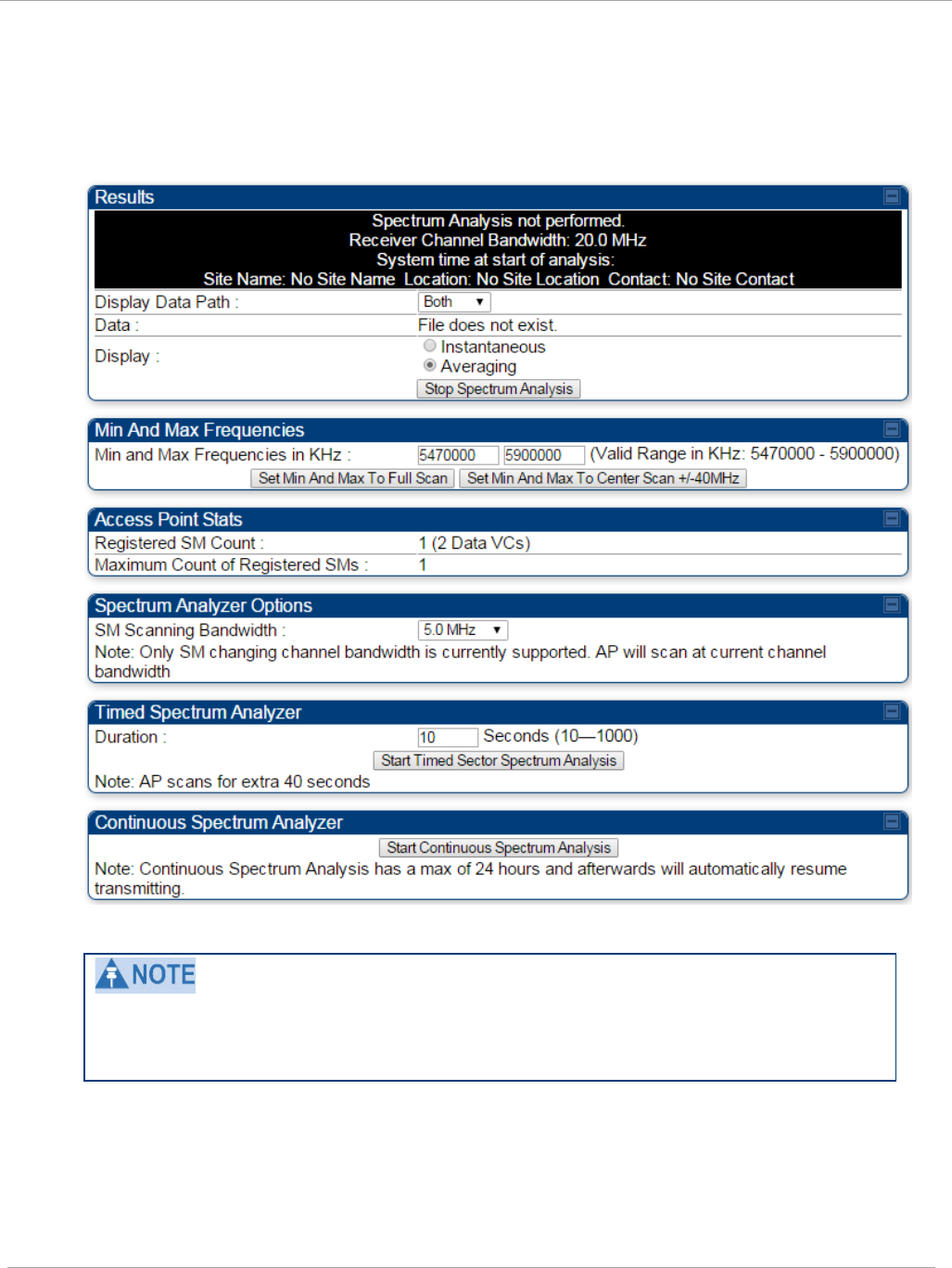
Task 12: Performing an Sector Wide SA PMP 450i and PTP 450i Configuration and User
Guide
Using Spectrum Analyzer tool
The SM and AP display the graphical spectrum analyzer. An example of the
Spectrum Analyzer tab is shown in Figure 62.
Figure 62 Spectrum Analyzer tab of the AP/ SM
Enabling “Perform Spectrum Analysis on Boot for configured Duration” will
increase SM registration time by the amount of seconds specified for the SM to
scan the spectrum upon boot.
New navigation features include:
• Results may be panned left and right through the scanned spectrum by clicking and
dragging the graph left and right
• Results may be zoomed in and out with the mouse wheel
pmp-0957 (April 2015) 171

PMP 450i and PTP 450i Configuration and User
Task 12: Performing an Sector Wide SA
When the mouse is positioned over a bar, the receive power level, frequency,
maximum and mean receive power levels are displayed above the graph
To keep the displayed data current, either set “Auto Refresh” on the module’s
Configuration => General.
172 pmp-0957 (April 2015)

Task 12: Performing an Sector Wide SA PMP 450i and PTP 450i Configuration and User
Guide
Table 56 Spectrum Analyzer attributes
Attribute Meaning
Display Data Path Both means that the vertical and horizontal paths are
displayed or an individual path may be selected to display
only a single-path reading.
Data For ease of parsing data and to facilitate automation, the
spectrum analyzer results may be saved as an XML file. To
save the results in an XML formatted file, right-click the
“SpectrumAnalysis.xml” link and save the file. If these
results are viewed in a browser, they are displayed in the
horizontal bar-graph fashion which was available prior to
12.1.
Display Instantaneous means that each reading (vertical bar) is
displayed with two horizontal lines above it representing the
max power level received (top horizontal line) and the
average power level received (lower horizontal line) at that
frequency.
Averaging means that each reading (vertical bar) is
displayed with an associated horizontal line above it
representing the max power level received at that frequency.
Registered SM
Count
This field displays the MAC address and Site Name of the
registered SM.
Maximum Count of
Registered SMs
This field displays the maximum number of registered SMs.
Duration This field allows operators to configure a specified time for
which the spectrum is scanned. If the entire spectrum is
scanned prior to the end of the configured duration, the
analyzer will restart at the beginning of the spectrum.
Continuous
Spectrum Analyzer
Start Continuous Spectrum Analysis
button ensures that
when the SM is powered on, it automatically scans the
spectrum for 10 seconds. These results may then be
accessed via the Tools => Spectrum Analyzer GUI page.
pmp-0957 (April 2015) 173
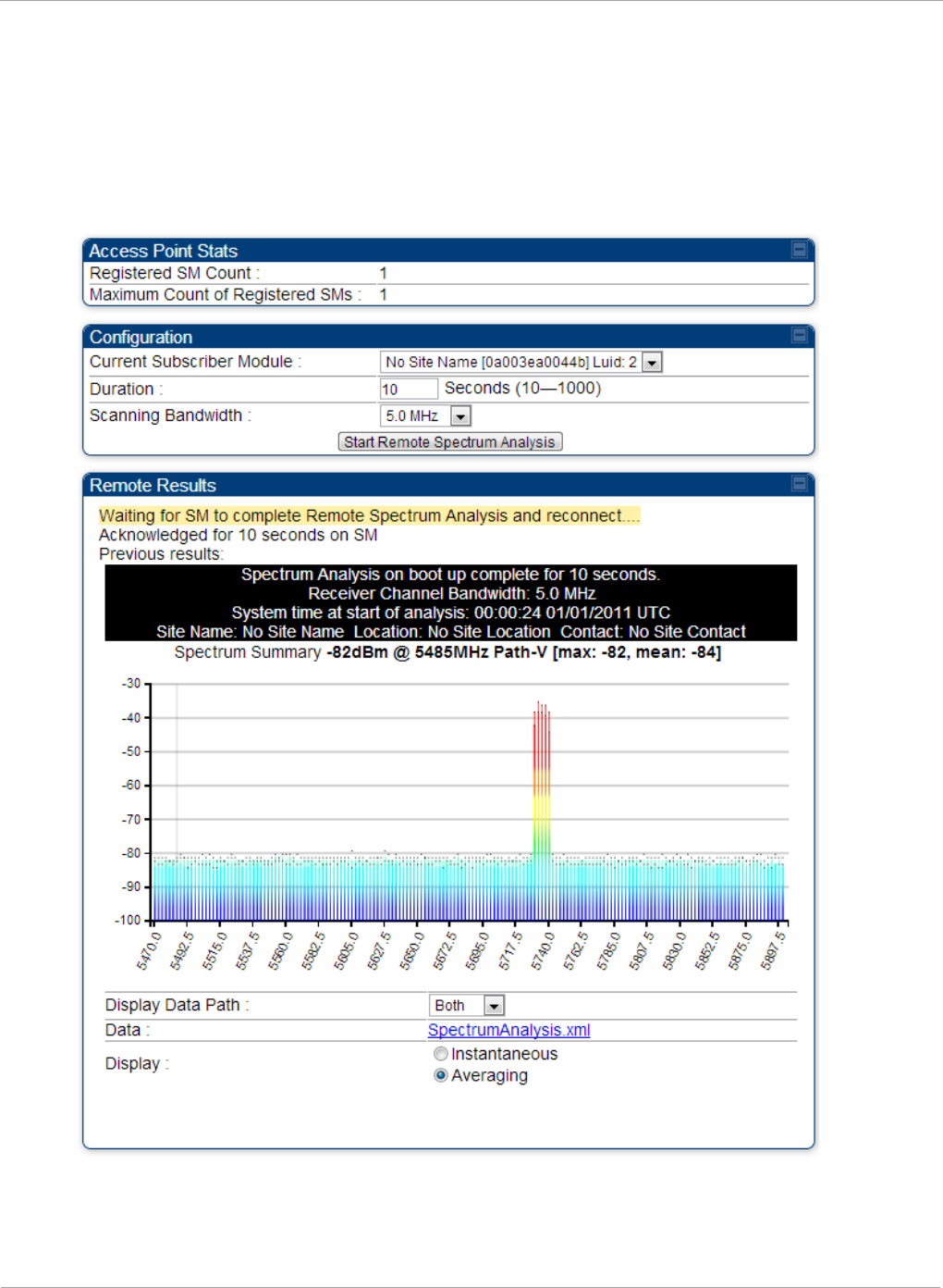
PMP 450i and PTP 450i Configuration and User
Task 12: Performing an Sector Wide SA
Using the Remote Spectrum Analyzer tool
The Remote Spectrum Analyzer tool in the AP provides additional flexibility in the
use of the spectrum analyzer in the SM. You can set the duration of 10 to 1000
seconds and select a SM from the drop-down list, then click the Start Remote
Spectrum Analysis button to launch the analysis from that SM.
Figure 63 Remote Spectrum Analyzer tab of the AP
174 pmp-0957 (April 2015)

Task 12: Performing an Sector Wide SA PMP 450i and PTP 450i Configuration and User
Guide
Table 57 Remote Spectrum Analyzer tab attributes
Attribute Meaning
Registered SM
Count
This field displays the number of SMs that were registered to
the AP before the SA was started. This helps the user know
all the SMs re-registered after performing a SA.
Maximum Count of
Registered SMs
This field displays the largest number of SMs that have been
simultaneously registered in the AP since it was last
rebooted. This count can provide some insight into sector
history and provide comparison between current and
maximum SM counts at a glance.
Current Subscriber
Module
The SM with which the Link Capacity Test is run.
Duration This field allows operators to configure a specified time for
which the spectrum is scanned. If the entire spectrum is
scanned prior to the end of the configured duration, the
analyzer will restart at the beginning of the spectrum.
Scanning
Bandwidth
This parameter defines the size of the channel scanned when
running the analyzer.
This feature proceeds in the following sequence:
1. The AP de-registers the target SM.
2. The SM scans (for the duration set in the AP tool) to collect data for the
bar graph.
3. The SM re-registers to the AP.
4. The AP displays the bar graph.
The bar graph is an HTML file, but can be changed to an XML file, which is then
easy to analyze through the use of scripts that you may write for parsing the data.
To transform the file to XML, click the “SpectrumAnalysis.xml” link below the
spectrum results. Although the resulting display appears mostly unchanged, the bar
graph is now coded in XML. You can now right-click on the bar graph for a Save
Target As option to save the Spectrum Analysis.xml file.
pmp-0957 (April 2015) 175

PMP 450i and PTP 450i Configuration and User
Task 13: Zero Touch Configuration Using DHCP
Option 66
Task 13: Zero Touch Configuration Using DHCP
Option 66
This feature allows an SM to get its configuration via DHCP option 66. This can be
used for the initial configuration of an SM as well as managing the configuration of
SMs on an ongoing basis. Here is how it works in brief :
1. When the SM boots up, if it is set to use DHCP client, it will send out a DHCP
Discover packet which includes a request for DHCP Option 66.
2. In case of a brand new SM out of the box, the DHCP Discover packet is sent out if
the SM connects to an AP using Installation Color Code (ICC), even though DHCP
client is not enabled in factory default config.
3. An appropriately configured DHCP server will respond with a DHCP Offer and
include a URL in response to the Option 66 request. The URL should point to the
configuration file.
4. The device will download the configuration file and apply it. The device will reboot
automatically if needed. (Note: this requires “rebootIfRequired” flag to be added to
the config file. See Creating a Golden config file on page 177.
Configuration Steps
The Zero Touch Configuraiton steps are the following:
1. Create the golden config file(s)
2. Host it on an TFTP/FTP/HTTP/HTTPS server
3. Configure the DHCP server to return the URL of the golden config file in option 66
When the SM boots up, it will get the URL for the golden config from the DHCP
server via option 66, download it and apply it.
If all the SMs are configured exactly the same, then you can create just new golden
config file that can be used with all SMs.
If the SMs are not configured the same, see if it is possible to group the SMs such
that SMs with the same configuration are served by the same DHCP pool. User can
then create multiple golden config files and configure the DHCP server to use the
appropriate config file for each pool.
User can also create one config file per SM. This provides the most flexibility, but is
practical only if you have a software tool/script to generate the config files for each
MAC address. The files should be named <mac>.cfg where <mac> is the MAC
address of the SM, and stored in the same directory on the file server. The DHCP
server should be configured to return the directory name ending with a ‘/’ in option
66. The SM will automatically add “<mac>.cfg” to the path and get its config file.
176 pmp-0957 (April 2015)

Task 13: Zero Touch Configuration Using DHCP
66
PMP 450i and PTP 450i Configuration and User
Guide
If some configuration is unique per SM, but rest of the configuration is common, the
SMs can be staged with the unique part, and use option 66 to manage the common
part. For example, if each SM needs to have its coordinates set, don’t include the
coordinates in the golden config file. Instead, configure the coordinates for each SM
manually. Manage the rest of the configuration using DHCP option 66.
Creating a Golden config file
The easiest way to create the golden config file is to configure an SM, export its
configuration and edit it. To export the configuration file from the GUI of the SM, go
to “Configuration > Unit Settings” tab, go to the “Download Configuration File”
section and click on the “<mac>.cfg” link. This will give you a text file in JSON
format. You can edit this file in a text editor but it’s easier to use a JSON editor like
https://www.jsoneditoronline.org/.
Strip down the config file to remove sections and entries that don’t care about, and
keep only the items that require changes. If there are many required changes, it can
easily get confusing. To identify the exact items changes, first reset the SM to
factory default, export the config file, make the necessary changes, export a second
config file, then use a tool like WinMerge (http://winmerge.org/) to identify the
differences.
The config file contains the following informational entries at the top level.
"cfgUtcTimestamp": "cfgUtcTimestamp",
"swVersion": "CANOPY 13.3 (Build 15) SM-AES",
"cfgFileString": "Canopy configuration file",
"srcMacAddress": "0a-00-3e-a2-c2-74",
"deviceType": "5.4/5.7GHz MIMO OFDM - Subscriber Module",
"cfgFileVersion": "1.0"
The “cfgUtcTimestamp”, “swVersion”, “srcMacAddress” and “deviceType” lines can
be deleted. Do not delete the “cfgFileString” and “cfgFileVersion” entries.
Next, create an object named “configFileParameters” at the top level. Under that,
add a parameter called “rebootIfRequired” and set it to true. This tells the SM to
reboot automatically if a reboot is needed to apply the new configuration.
A sample configuration file that has been edited for use via DHCP option 66 is given
below.
{
"userParameters": {
"smNetworkConfig": {
"networkAccess": 1
},
pmp-0957 (April 2015) 177

PMP 450i and PTP 450i Configuration and User
Task 13: Zero Touch Configuration Using DHCP
Option 66
"location": {
"siteName": "Test site"
},
"smRadioConfig": {
"frequencyScanList": [
5475000,
5480000
],
"colorCodeList": [
{
"colorCode": 42,
"priority": 1
}
]
},
"networkConfig": {
"lanDhcpState": 1
}
},
"cfgFileVersion": "1.0",
"cfgFileString": "Canopy configuration file",
"configFileParameters": {
"rebootIfRequired": true
}
}
When configuration is imported, only the items that exist in the configuration file
are modified. Parameters that are not in the imported file are not changed. If user
wish to revert those settings to their factory default values, please add a
“setToDefaults” item under “configFileParameters” section with a value of true.
"cfgFileVersion": "1.0",
"cfgFileString": "Canopy configuration file",
"configFileParameters": {
"rebootIfRequired": true,
"setToDefaults": true
}
In case, the SM needs to fetch the configuration file on each boot up even when not
connecting to AP via ICC, set “Network Accessibility” to “Public” and “DHCP State”
to “Enabled” in the “Configuration > IP” page before exporting the configuration.
178 pmp-0957 (April 2015)
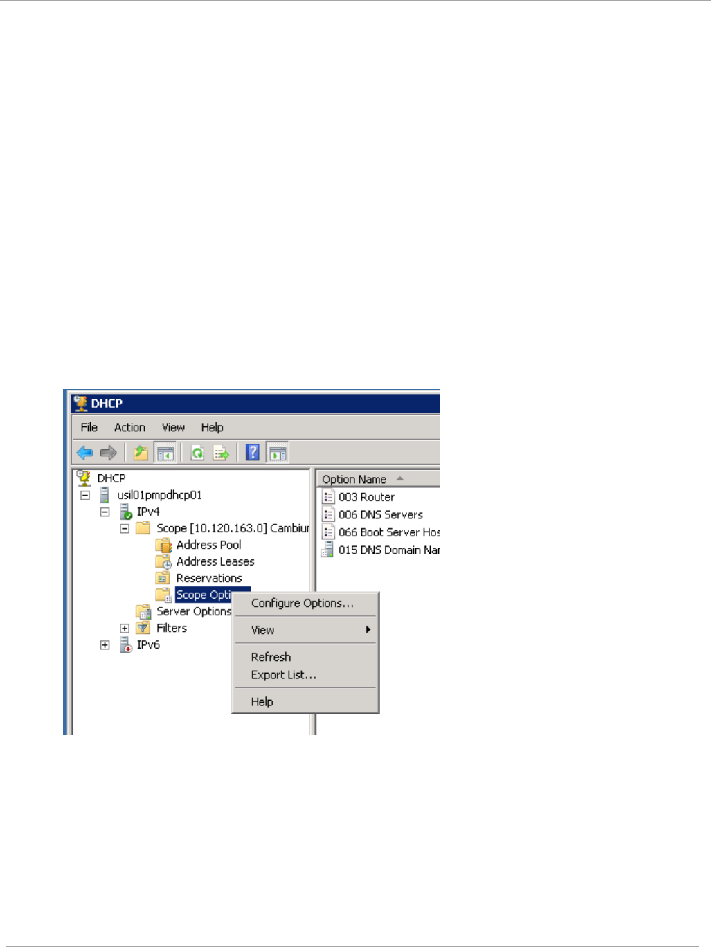
Task 13: Zero Touch Configuration Using DHCP
66
PMP 450i and PTP 450i Configuration and User
Guide
Hosting the config file
Copy the golden configuration file to an FTP, TFTP, HTTP or HTTPS server. This
location can be password protected; you just have to include the user name and
password in the URL.
DHCP server configuration
Configure DHCP server to return the full URL to the golden config file as the value
of DHCP option 66.
The following example explains how to make the change for Windows Server 2008.
Adapt it to your specific DHCP server.
1. Click “Start > Administrative Tools > DHCP”
2. If you have multiple “Scopes” defined, identify the correct “Scope” that will serve IP
addresses for the SMs
3. Right click on “Scope Option” under the correct “Scope” and select “Configure
Options”
4. In the “Scope Options” dialog, scroll down to “066 Boot Server Host Name”, select
the checkbox and enter the full URL to the golden config file as the “String value”.
Then click “OK”.
pmp-0957 (April 2015) 179
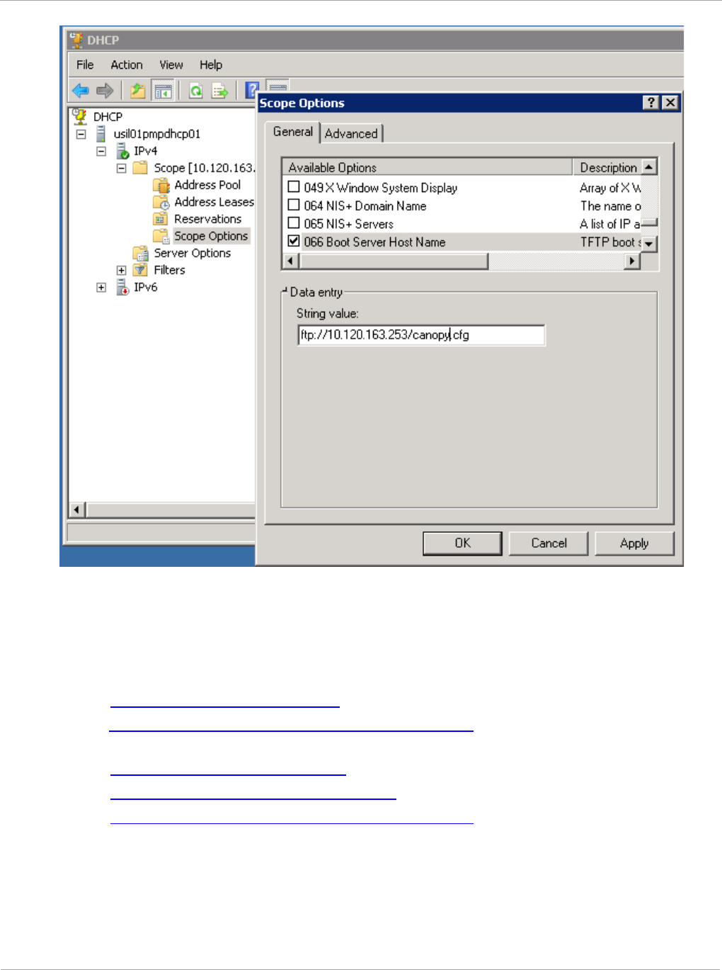
PMP 450i and PTP 450i Configuration and User
Task 13: Zero Touch Configuration Using DHCP
Option 66
5. In the DHCP snap-in window, right click and “Refresh” to see the DHCP option 66 in
the list of DHCP options
Supported URL Formats
FTP, TFTP, HTTP and HTTPS URLs are supported. Some examples are given below.
- ftp://10.120.163.253/canopy.cfg
- ftp://admin:admin123@10.120.163.253/canopy.cfg (login as admin with
password admin123)
- tftp://10.120.163.253/canopy.cfg
- http://10.120.163.253/golden-config.cfg
- https://10.120.163.253/smconfig/golden-config.cfg
User can also specify the URL pointing to a directory and not a specific file.
Terminate the URL with a ‘/’ to indicate that it is a directory and not a file. Use this
format when each SM has its own individual config file. The directory should contain
files named “<mac>.cfg”, one for each SM..
180 pmp-0957 (April 2015)
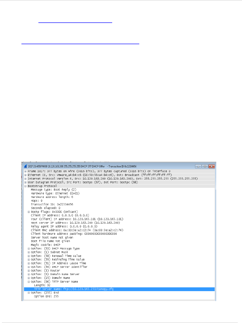
Task 13: Zero Touch Configuration Using DHCP
66
PMP 450i and PTP 450i Configuration and User
Guide
For example:
- ftp://10.120.163.253/smconfig/
In this case, the SM will append “<mac>.cfg” to the path and try to get that file. For
example, if the SM’s MAC address is 0a-00-3e-a2-c2-74, it will request for
ftp://10.120.163.253/smconfig/0a003ea2c274.cfg. This mechanism can be used to
serve individual config file for each SM.
Troubleshooting
1. Make sure the SM is running 13.3 or newer version of software.
2. If the SM has factory default config, confirm ICC is enabled on the AP, so the SM
can connect to it.
3. If the SM is connecting to the AP using a color code other than ICC, make sure the
SM has “Network Accessibility” set to “Public” and “DHCP State” set to “Enabled”
in the “Configuration > IP” page.
4. Make sure the golden config file does not turn off “Network Accessibility” or “DHCP
State”. If it does, the SM will no longer request the config file when it is rebooted.
5. Check the event log of the SM to see the status of the configuration file import
including any errors that prevented it from importing the file.
6. Capture the DHCP Offer packet from the DHCP server to the SM and verify that
Option 66 has the expected URL.
pmp-0957 (April 2015) 181

PMP 450i and PTP 450i Configuration and User
Task 14: Configuring Radio via config file
Task 14: Configuring Radio via config file
The PMP 450i supports export and import of a configuration file from the AP or SM
as a text file. The configuration file is in JSON format.
To export or import the configuration file, the logged in user needs to be an
ADMINISTRATOR and it must not be a “read-only” account.
The exported configuration file contains the complete configuration including all the
default values. To keep a backup of the current configuration, the file can be saved
as-is and imported later.
While importing a configuration file, it can be either imported the full configuration
or a sparse configuration containing only the items that need to be changed. If a
sparse configuration file is imported, only the items in the file will be imported.
Other configuration will remain unchanged. There could also be used a special flag
in the configuration file to tell the device to apply the configuration starting from
factory default (Refer Special Headers for configuration file on page 183).
Import and Export of config file
Procedure 12 Export the configuration from the GUI
1 Login to the GUI and go to Configuration → Unit Settings.
2 Under Download Configuration File tab, click on the “<mac>.cfg” link, where
<mac> is the MAC address of the device (for example, “01003ea2c274.cfg”).
3 Save the file to the local disk.
Procedure 13 Import the configuration from the GUI
1 Login to the GUI and go to Configuration → Unit Settings.
2 Click on “Browse” button under “Upload and Apply Configuration File” tab
and select the configuration file from disk.
3 Click “Upload” followed by “Apply Configuration File” button click.
4 The “Status of Configuration File” section will show the results of the upload.
5 Review it to make sure there are no errors. Then click on “Reboot” to reboot
with the imported configuration
182 pmp-0957 (April 2015)
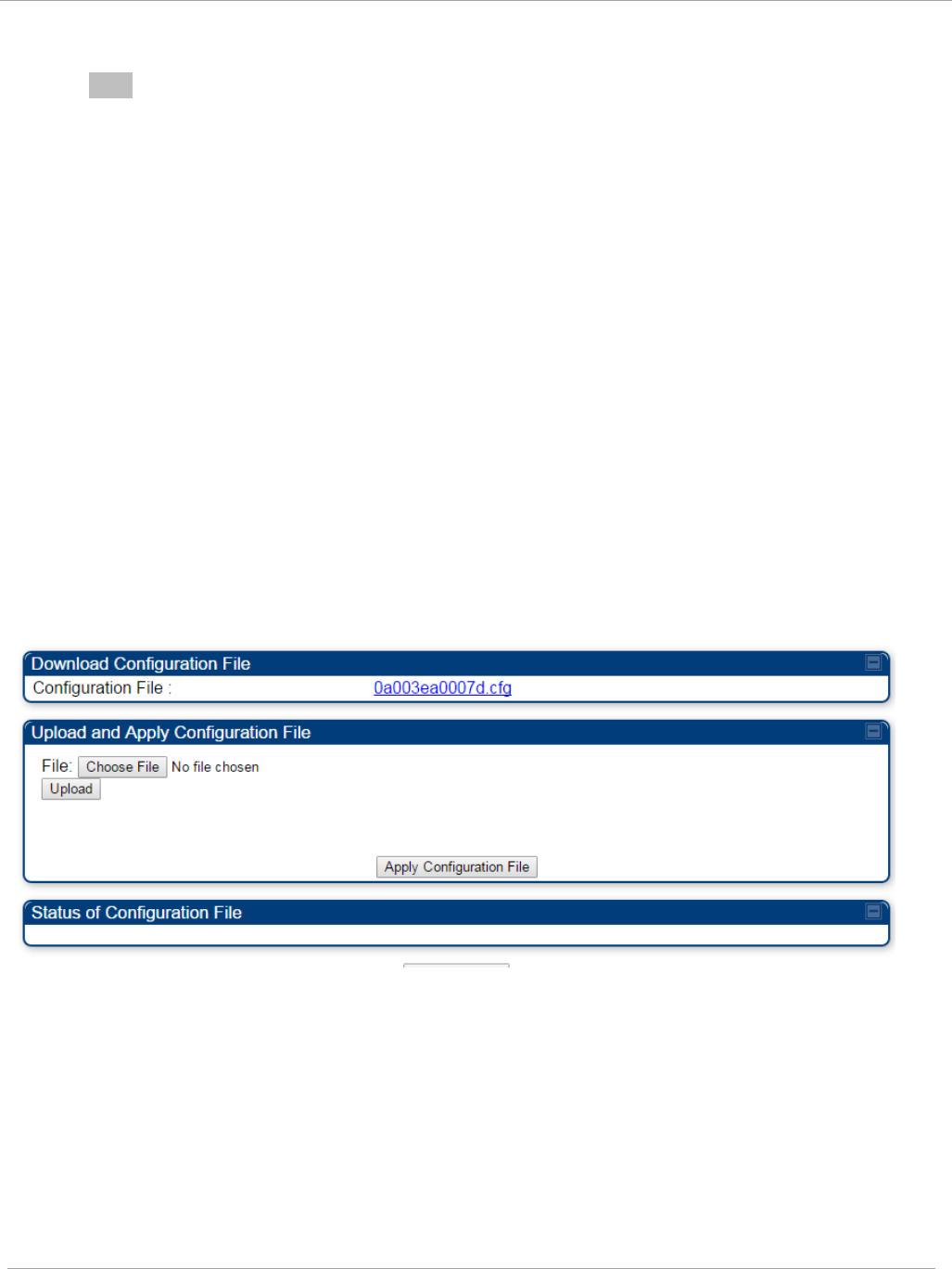
Task 14: Configuring Radio via config file PMP 450i and PTP 450i Configuration and User
Guide
Procedure 14 Special Headers for configuration file
1 A "configFileParameters" section can be added to the header to control the
behaviour of the device when importing configuration.
{
"cfgFileString": "Canopy configuration file",
"cfgFileVersion": "1.0",
"configFileParameters": {
"setToDefaults":true,
"rebootIfRequired":true,
}
}
The "setToDefaults" when set to "true" tell the device to reset to factory default
configuration and apply the configuration in the file on top of that. So any
attribute not in the configuration file will be set to its factory default value. By
default, the configuration in the file is merged with the existing configuration on
the device.
The "rebootIfRequired" flag when set to "true" tell the device to reboot
automatically if needed to apply the configuration change. By default, the device
will not reboot automatically.
Figure 64 Configuration File upload and download page
pmp-0957 (April 2015) 183

PMP 450i and PTP 450i Configuration and User
Task 15: Configuring a RADIUS server
Task 15: Configuring a RADIUS server
Configuring a RADIUS server in a PMP 450i network is optional, but can provide
added security, increase ease of network management and provide usage-based
billing data.
Understanding RADIUS for
PMP 450i
PMP 450i modules include support for the RADIUS (Remote Authentication Dial In
User
Service)
protocol supporting Authentication and Accounting.
RADIUS
Functions
RADIUS protocol support provides the
following
functions:
• SM Authentication allows only known SMs onto the network (blocking
“rogue”
SMs), and can be configured to ensure SMs are connecting to a known
network
(preventing SMs from connecting to “rogue” APs). RADIUS authentication is
used
for
SMs,
but
is not used for APs.
• SM Configuration: Configures authenticated SMs with MIR (Maximum Information
Rate), CIR (Committed Information Rate), High Priority, and VLAN (Virtual LAN)
parameters from the RADIUS server when a SM registers to an AP.
• SM Accounting provides support for RADIUS accounting messages for usage-based
billing. This accounting includes indications for subscriber session establishment,
subscriber session disconnection, and bandwidth usage per session for each SM that
connects to the AP.
• Centralized AP and SM user name and password management allows AP
and
SM usernames and access levels (Administrator, Installer, Technician) to
be
centrally
administered in the RADIUS server instead of on each radio and tracks
access
events
(logon/logoff) for each username on the RADIUS server. This accounting does
not
track and
report
specific configuration actions performed on radios or pull statistics
such as
bit
counts from the radios. Such functions require an Element Management
System
(EMS) such as Cambium Networks Wireless Manager. This accounting is
not
the ability to perform accounting functions on the subscriber/end
user/customer
account.
•
Framed IP
allows o
perators to use a RADIUS server to assign management IP
addressing to SM modules (framed IP address).
Tested RADIUS Servers
The Canopy RADIUS implementation has been tested and is supported
on
• FreeRADIUS, Version
2.1.8
• Aradial RADIUS, Version
5.1.12
184 pmp-0957 (April 2015)

Task 15: Configuring a RADIUS server PMP 450i and PTP 450i Configuration and User
Guide
Aradial 5.3 has a bug that prevents “remote device login”, so
doesn’t
support the
user name and password management
feature.
Choosing Authentication Mode and Configuring for
Authentication Servers - AP
On the AP’s Configuration => Security tab, select the RADIUS AAA
Authentication Mode. The following describes the
other
Authentication Mode
options for reference, and then the RADIUS AAA
option.
•
Disabled
: Requires no authentication. Any SM (except a SM that itself has been
configured to
require
RADIUS authentication by enabling Enforce Authentication as
described below) is allowed to
register
to the
AP.
• Authentication Server: Authentication Server in this instance refers to Wireless
Manager in BAM-only mode. Authentication is
required
for a SM to register to the AP.
Only SMs listed by MAC address in the Wireless Manager database is
allowed to
register to the
AP.
• AP Pre-Shared
Key
: Canopy offers a pre-shared key authentication option. In this
case, an identical key
must
be entered in the Authentication Key field on the AP’s
Configuration > Security tab and in the Authentication Key field on each desired SM’s
Configuration > Security
tab.
• RADIUS
AAA
: To support RADIUS authentication of SMs, on the AP’s Configuration
> Security tab
select
RADIUS AAA. Only properly configured SMs with a valid
certificate is allowed to
register
to the
AP.
When RADIUS AAA is selected, up to 3 Authentication Server (RADIUS Server)
IP
addresses
and Shared Secrets can be configured. The IP address(s) configured
here
must
match the IP address(s) of the RADIUS server(s). The shared secret(s)
configured here
must
match the shared secret(s) configured in the RADIUS
server(s). Servers 2 and 3 are meant
for
backup and reliability, not splitting the
database. If Server 1 doesn’t respond, Server 2 is
tried,
and then
server
3. If
Server 1 rejects authentication, the SM is denied entry to the network, and does
not
progress trying the other
servers.
The default IP address is 0.0.0.0.
The
default Shared Secret is
“CanopySharedSecret”. The Shared Secret can be up to 32
ASCII
characters (no
diacritical marks or ligatures, for
example).
pmp-0957 (April 2015) 185
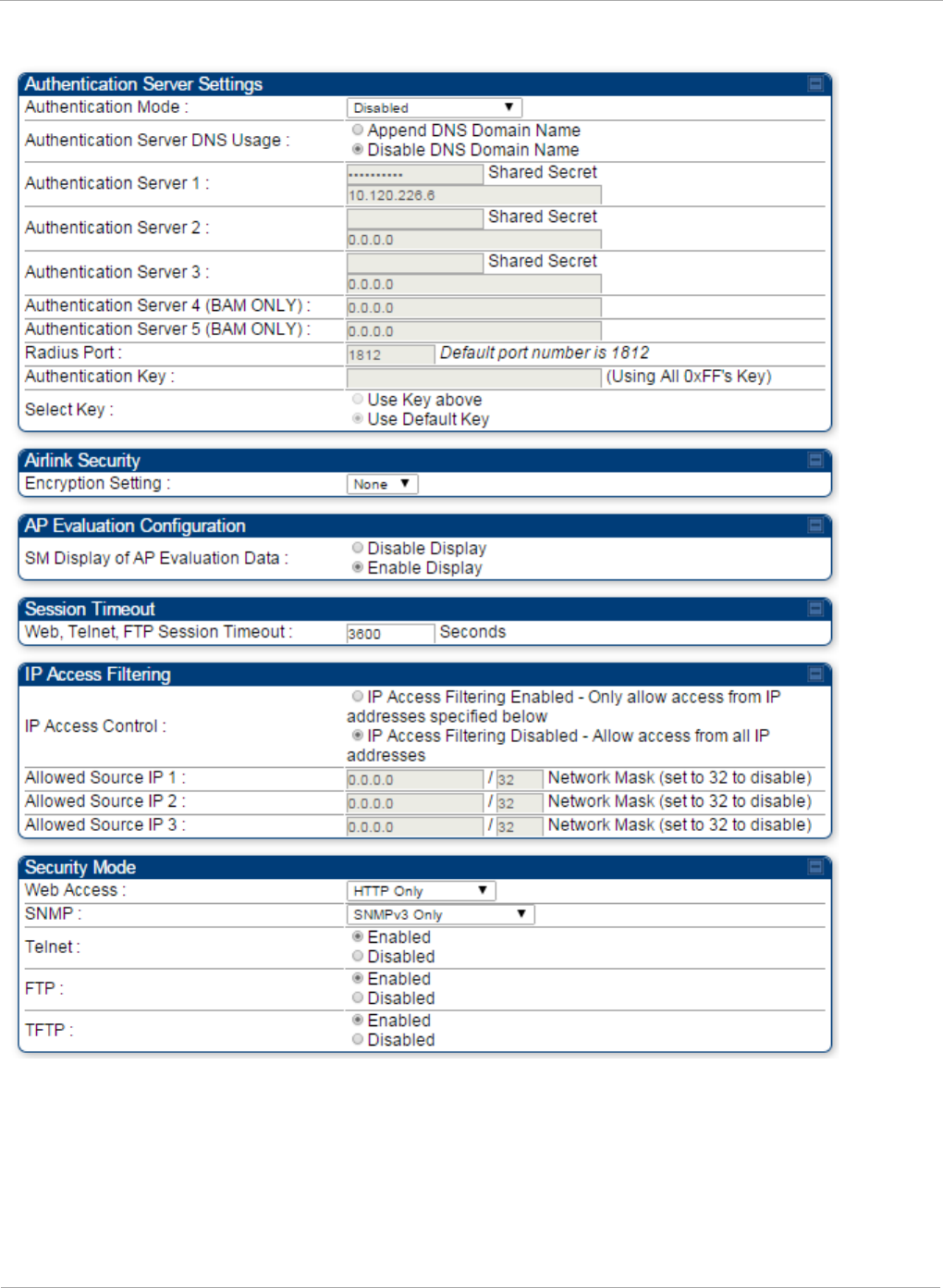
PMP 450i and PTP 450i Configuration and User
Task 15: Configuring a RADIUS server
Figure 65 Security tab of the AP
186 pmp-0957 (April 2015)

Task 15: Configuring a RADIUS server PMP 450i and PTP 450i Configuration and User
Guide
Table 58 Security tab attributes
Attribute Meaning
Authentication
Mode
Operators may use this field to select the following authentication
modes:
Disabled—the AP requires no SMs to authenticate.
Authentication Server —the AP requires any SM that attempts
registration to be authenticated in Wireless Manager before
registration.
AP PreShared Key - The AP acts as the authentication server to its
SMs and will make use of a user-configurable pre-shared
authentication key. The operator enters this key on both the AP and
all SMs desired to register to that AP. There is also an option of
leaving the AP and SMs at their default setting of using the “Default
Key”. Due to the nature of the authentication operation, if you want
to set a specific authentication key, then you MUST configure the
key on all of the SMs and reboot them BEFORE enabling the key
and option on the AP. Otherwise, if you configure the AP first, none
of the SMs is able to register.
RADIUS AAA - When RADIUS AAA is selected, up to 3
Authentication Server (RADIUS Server) IP addresses and Shared
Secrets can be configured. The IP address(s) configured here must
match the IP address(s) of the RADIUS server(s). The shared
secret(s) configured here must match the shared secret(s)
configured in the RADIUS server(s). Servers 2 and 3 are meant for
backup and reliability, not for splitting the database. If Server 1
doesn’t respond, Server 2 is tried, and then server 3. If Server 1
rejects authentication, the SM is denied entry to the network and
does not progress trying the other servers.
Authentication
Server DNS Usage
The management DNS domain name may be toggled such that the
name of the authentication server only needs to be specified and the
DNS domain name is automatically appended to that name.
Authentication
Server 1
Enter the IP address or server name of the authentication server
(RADIUS or WM) and the Shared Secret configured in the
authentication server. When Authentication Mode RADIUS AAA
is selected, the default value of Shared Secret is
“CanopySharedSecret”. The Shared Secret may consist of up to 32
ASCII characters.
Authentication
Server 2
Authentication
Server 3
Authentication
Server 4 (BAM
Only)
pmp-0957 (April 2015) 187

PMP 450i and PTP 450i Configuration and User
Task 15: Configuring a RADIUS server
Attribute Meaning
Authentication
Server 5 (BAM
Only)
Radius Port This field allows the operator to configure a custom port for RADIUS
server communication. The default value is
1812
.
Authentication Key The authentication key is a 32-character hexadecimal string used
when Authentication Mode is set to AP Pre-Shared Key. By
default, this key is set to
0xFFFFFFFFFFFFFFFFFFFFFFFFFFFFFFFF.
Selection Key This option allows operators to choose which authentication key is
used:
Use Key above means that the key specified in Authentication
Key is used for authentication
Use Default Key means that a default key (based off of the SM’s
MAC address) is used for authentication
Encryption Key Specify the type of airlink security to apply to this AP. The
encryption setting must match the encryption setting of the SMs.
None provides no encryption on the air link.
DES (Data Encryption Standard): An over-the-air link encryption
option that uses secret 56-bit keys and 8 parity bits. DES performs a
series of bit permutations, substitutions, and recombination
operations on blocks of data. DES encryption does not affect the
performance or throughput of the system.
AES (Advanced Encryption Standard): An over-the-air link
encryption option that uses the Rijndael algorithm and 128-bit keys
to establish a higher level of security than DES. AES products are
certified as compliant with the Federal Information Processing
Standards (FIPS 197) in the U.S.A.
SM Display of AP
Evaluation Data
You can use this field to suppress the display of data about this AP
on the AP Evaluation tab of the Tools page in all SMs that register.
Web, Telnet, FTP
Session Timeout
Enter the expiry in seconds for remote management sessions via
HTTP, telnet, or ftp access to the AP.
IP Access Control You can permit access to the AP from any IP address (IP Access
Filtering Disabled) or limit it to access from only one, two, or three
IP addresses that you specify (IP Access Filtering Enabled). If you
select IP Access Filtering Enabled, then you must populate at
least one of the three Allowed Source IP parameters or have no
access permitted from any IP address
Allowed Source IP
1
If you selected IP Access Filtering Enabled for the IP Access
Control parameter, then you must populate at least one of the three
188 pmp-0957 (April 2015)

Task 15: Configuring a RADIUS server PMP 450i and PTP 450i Configuration and User
Guide
Attribute Meaning
Allowed Source IP
2
Allowed Source IP parameters or have no access permitted to the
AP from any IP address. You may populate as many as all three.
If you selected IP Access Filtering Disabled for the IP Access
Control parameter, then no entries in this parameter are read, and
access from all IP addresses is permitted.
Allowed Source IP
3
Web Access The Radio supports secured and non-secured web access protocols.
Select suitable web access from drop down list:
• HTTP Only – provides non-secured web access. The radio to be
accessed via http://<IP of Radio>.
• HTTPs Only – provides a secured web access. The radio to be
accessed via http://<IP of Radio>.
• HTTP and HTTPs – If enabled, the radio can be accessed via
both http and https.
SNMP This option allows to configure SNMP agent communication version.
It can be selected from drop down list :
• SNMPv2c Only – Enables SNMP v2 community protocol.
• SNMPv3 Only – Enables SNMP v3 protocol. It is secured
communication protocol.
• SNMPv2c and SNMPv3 – It enables both the protocols.
Telnet This option allows to Enable and Disable Telnet access to the
Radio.
FTP This option allows to Enable and Disable FTP access to the Radio.
TFTP This option allows to Enable and Disable TFTP access to the Radio.
pmp-0957 (April 2015) 189

PMP 450i and PTP 450i Configuration and User
Task 15: Configuring a RADIUS server
SM Authentication Mode – Require RADIUS or Follow
AP
If it is desired that a SM will only authenticate to an AP that is using RADIUS, on the
SM’s
Configuration Security tab set Enforce Authentication to AAA. With this enabled,
SM
does
not register to an AP that has any Authentication Mode other than RADIUS
AAA
selected
.
If it is desired that a SM use the authentication method configured on the AP it is
registering
to, set Enforce Authentication to Disabled. With Enforce
Authentication disabled, a SM will attempt to register
using
whichever
Authentication Mode is configured on the AP it is attempting to register
to.
Having SMs to use RADIUS by enabling Enforce Authentication avoids the
security issue of SMs possibly registering to “rogue” Aps, which have
authentication
disabled.
190 pmp-0957 (April 2015)
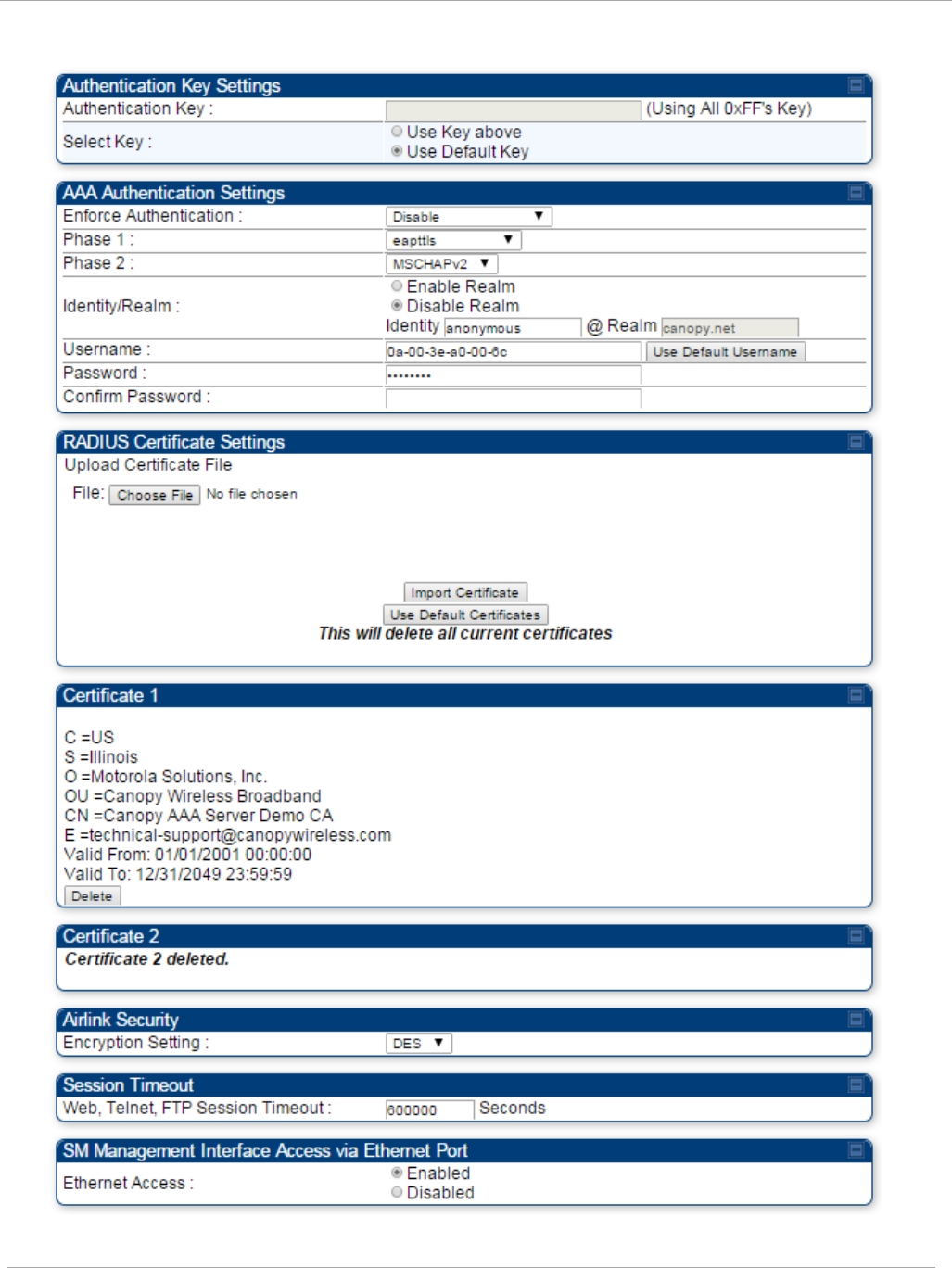
Task 15: Configuring a RADIUS server PMP 450i and PTP 450i Configuration and User
Guide
Figure 66 Security tab of the SM
pmp-0957 (April 2015) 191
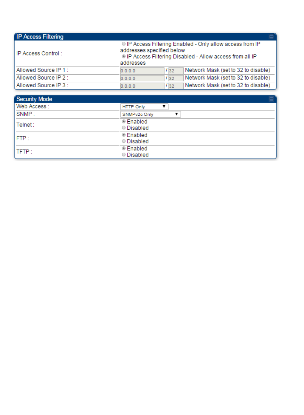
PMP 450i and PTP 450i Configuration and User
Task 15: Configuring a RADIUS server
Continue…
192 pmp-0957 (April 2015)

Task 15: Configuring a RADIUS server PMP 450i and PTP 450i Configuration and User
Guide
Table 59 SM Security tab attributes
Attribute Meaning
Authentication Key
The authentication key is a 32-character hexadecimal string used
when Authentication Mode is set to AP PreShared Key. By
default, this key is set to
0xFFFFFFFFFFFFFFFFFFFFFFFFFFFFFFFF.
Select Key
This option allows operators to choose which authentication key is
used:
Use Key above means that the key specified in Authentication
Key is used for authentication
Use Default Key means that a default key (based off of the SM’s
MAC address) is used for authentication
Enforce
Authentication
The SM may enforce authentication types of AAA and AP Pre-
sharedKey. The SM will not finish the registration process if the
AP is not using the configured authentication method (and the SM
locks out the AP for 15 minutes). Enforce Authentication default
setting is Disable.
Phase 1
The protocols supported for the Phase 1 (Outside Identity) phase
of authentication are
EAPTTLS (Extensible Authentication
Protocol Tunneled Transport Layer
Security) or MSCHAPv2
(Microsoft Challenge-Handshake Authentication Protocol version
2).
Phase 2
Select the desired Phase 2 (Inside Identity) authentication
protocol from the Phase 2 options of PAP (Password
Authentication Protocol), CHAP (Challenge Handshake
Authentication
Protocol), and MSCHAP (Microsoft’s version of
CHAP, version 2 is used). The protocol
must
be
consistent with
the authentication protocol configured on the RADIUS
server.
Identity/Realm
If Realms are being used, select Enable Realm and configure an
outer identity in the
Identity
field and a Realm in the Realm
field. These must match the Phase 1/Outer Identity and
Realm
configured in the RADIUS server. The default Identity is
“anonymous”. The Identity can be
up
to
128 non-special (no
diacritical markings) alphanumeric characters. The default
Realm
is
“canopy.net”. The Realm can also be up to 128 non-
special alphanumeric
characters.
Configure an outer Identity in the Username field. This must
match the Phase
1/Outer
Identity username configured in the
RADIUS server. The default Phase 1/Outer
Identity
Username is
“anonymous”. The Username can be up to 128 non-special (no
diacritical
markings) alphanumeric
characters.
pmp-0957 (April 2015) 193

PMP 450i and PTP 450i Configuration and User
Task 15: Configuring a RADIUS server
Attribute Meaning
Username
Enter a Username for the SM. This must match the username
configured for the SM on
the
RADIUS server. The default
Username is the SM’s MAC address. The Username can be up
to
128 non-special (no diacritical markings) alphanumeric
characters.
Password Enter the desired password for the SM in the Password and
Confirm Password fields.
The
Password must match the
password configured for the SM on the RADIUS server.
The
default Password is “password”. The Password can be up to 128
non-special (no
diacritical
markings) alphanumeric
characters.
Confirm Password
Upload Certificate
File
To upload a certificate manually to a SM, first load it in a known
place on your PC
or
network
drive, then click on a Delete button
on one of the Certificate description blocks to delete a certificate
to provide space for your certificate. Click on Choose File,
browse to
the
location of the certificate, and click the Import
Certificate button, and then reboot the radio to use the new
certificate.
When a certificate is in use, after the SM successfully registers
to an AP, an indication of In
Use
will appear in the description
block of the certificate being
used.
The public certificates installed on the SMs are used with the
private certificate on the
RADIUS
server to provide a
public/private key encryption
system.
Up to 2 certificates can be resident on a SM. An installed
certificate can be deleted
by
clicking the Delete button in the
certificate’s description block on the Configuration >
Security
tab. To restore fhe 2 default certificates, click the Use Default
Certificates button in
the
RADIUS Certificate Settings
parameter block and reboot the
radio.
Encryption Setting
Specify the type of airlink security to apply to this AP. The
encryption setting must match the encryption setting of the SMs.
None provides no encryption on the air link.
DES (Data Encryption Standard): An over-the-air link encryption
option that uses secret 56-bit keys and 8 parity bits. DES performs
a series of bit permutations, substitutions, and recombination
operations on blocks of data. DES encryption does not affect the
performance or throughput of the system.
AES (Advanced Encryption Standard): An over-the-air link
encryption option that uses the Rijndael algorithm and 128-bit
keys to establish a higher level of security than DES. AES products
are certified as compliant with the Federal Information Processing
Standards (FIPS 197) in the U.S.A.
194 pmp-0957 (April 2015)

Task 15: Configuring a RADIUS server PMP 450i and PTP 450i Configuration and User
Guide
Attribute Meaning
Web, Telnet, FTP
Session Timeout
Enter the expiry in seconds for remote management sessions via
HTTP, telnet or ftp access to the AP.
Ethernet Access
If you want to prevent any device that is connected to the Ethernet
port of the SM from accessing the management interface of the
SM, select Ethernet Access Disabled. This selection disables
access through this port to via HTTP (the GUI), SNMP, telnet,
FTP, and TFTP. With this selection, management access is
available through only the RF interface via either an IP address (if
Network Accessibility is set to Public on the SM) or the Session
Status or Remote Subscribers tab of the AP.. See IP Access
Control below.
If you want to allow management access through the Ethernet
port, select Ethernet Access Enabled. This is the factory default
setting for this parameter.
IP Access Control
You can permit access to the AP from any IP address (IP Access
Filtering Disabled) or limit it to access from only one, two, or
three IP addresses that you specify (IP Access Filtering
Enabled). If you select IP Access Filtering Enabled, then you
must populate at least one of the three Allowed Source IP
parameters or have no access permitted from any IP address
Allowed Source IP
1
If you selected IP Access Filtering Enabled for the IP Access
Control parameter, then you must populate at least one of the
three Allowed Source IP parameters or have no access permitted
to the AP from any IP address. You may populate as many as all
three.
If you selected IP Access Filtering Disabled for the IP Access
Control parameter, then no entries in this parameter are read,
and access from all IP addresses is permitted.
Allowed Source IP
2
Allowed Source IP
3
Web Access The Radio supports secured and non-secured web access
protocols. Select suitable web access from drop down list:
• HTTP Only – provides non-secured web access. The radio to
be accessed via http://<IP of Radio>.
• HTTPs Only – provides a secured web access. The radio to be
accessed via http://<IP of Radio>.
• HTTP and HTTPs – If enabled, the radio can be accessed via
both http and https.
pmp-0957 (April 2015) 195

PMP 450i and PTP 450i Configuration and User
Task 15: Configuring a RADIUS server
Attribute Meaning
SNMP This option allows to configure SNMP agent communication
version. It can be selected from drop down list :
• SNMPv2c Only – Enables SNMP v2 community protocol.
• SNMPv3 Only – Enables SNMP v3 protocol. It is secured
communication protocol.
• SNMPv2c and SNMPv3 – It enables both the protocols.
Telnet This option allows to Enable and Disable Telnet access to the
Radio.
FTP This option allows to Enable and Disable FTP access to the
Radio.
TFTP This option allows to Enable and Disable TFTP access to the
Radio.
196 pmp-0957 (April 2015)

Task 15: Configuring a RADIUS server PMP 450i and PTP 450i Configuration and User
Guide
SM - Phase 1 (Outside Identity) parameters and
settings
The protocols supported for the Phase 1 (Outside Identity) phase of authentication
are
eapttls (Extensible Authentication Protocol Tunneled Transport Layer
Security) and
eapMSChapV2
(Extensible Authentication Protocol – Microsoft Challenge-Handshake
Authentication Protocol).
Configure an outer Identity in the Username field. This must match the Phase
1/Outer
Identity username configured in the RADIUS server. The default Phase 1/Outer
Identity
Username is “anonymous”. The Username can be up to 128 non-special (no
diacritical
markings) alphanumeric
characters.
If Realms are being used in the RADIUS system
(eapttls only), select Enable Realm and configure an outer identity in the
Identity
field and
a Realm in the Realm field. These must match the Phase 1/Outer Identity and
Realm
configured in the RADIUS server. The default Identity is “anonymous”. The Identity can be
up
to
128 non-special (no diacritical markings) alphanumeric characters. The default Realm
is
“canopy.net”. The Realm can also be up to 128 non-special alphanumeric
characters.
SM - Phase 2 (Inside Identity) parameters and
settings
If using eapttls for Phase 1 authentication, select the desired Phase 2 (Inside Identity)
authentication protocol from the Phase 2 options of PAP (Password Authentication
Protocol), CHAP (Challenge Handshake
Authentication
Protocol), and MSCHAPv2
(Microsoft’s version of CHAP). The protocol
must
be
consistent with the authentication
protocol configured on the RADIUS
server.
Enter a Username for the SM. This must
match the username configured for the SM on
the
RADIUS server. The default
Username is the SM’s MAC address. The Username can be up
to
128 non-special (no
diacritical markings) alphanumeric
characters.
Enter the desired password for the SM in the Password and Confirm Password fields.
The
Password must match the password configured for the SM on the RADIUS server.
The
default Password is “password”. The Password can be up to 128 non-special (no
diacritical
markings) alphanumeric
characters.
Handling Certificates
Managing SM Certificates via the SM GUI
The default public Canopy certificates are loaded into SMs upon factory software
installation. The default certificates are not secure and are intended for
use
during lab and field trials as part of gaining experience with the RADIUS
functionalities or as
an
option during debug. For secure operation, an operator will
want to create or procure their
own
certificates. Resetting a SM to its factory
defaults will remove the current certificates and restore the default certificates.
Up to two certificates can be resident on a SM. An installed certificate can be
deleted
by
clicking the Delete button in the certificate’s description block on the
Configuration >
Security
tab. To restore fhe 2 default certificates, click the Use
Default Certificates button in
the
RADIUS Certificate Settings parameter
block and reboot the
radio.
pmp-0957 (April 2015) 197
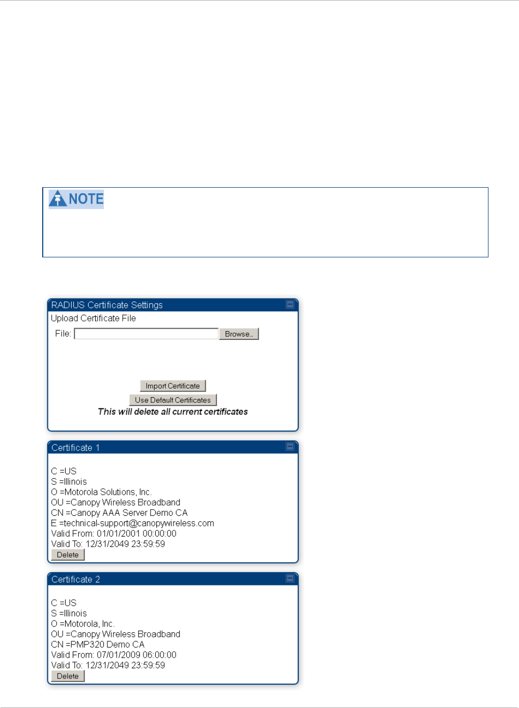
PMP 450i and PTP 450i Configuration and User
Task 15: Configuring a RADIUS server
To upload a certificate manually to a SM, first load it in a known place on your PC
or
network
drive, then click on a Delete button on one of the Certificate
description blocks to delete a certificate to provide space for your certificate. Click
on Choose File, browse to
the
location of the certificate, and click the Import
Certificate button, and then reboot the radio to use the new certificate.
When a certificate is in use, after the SM successfully registers to an AP, an
indication of In
Use
will appear in the description block of the certificate being
used.
The public certificates installed on the SMs are used with the private certificate on
the
RADIUS
server to provide a public/private key encryption
system.
Root certificates of more than one level (Example - a certificate from someone who
received their CA from Verisign) fails. Certificates must be either root or self-
signed.
Figure 67 SM Certificate Management
198 pmp-0957 (April 2015)

Task 15: Configuring a RADIUS server PMP 450i and PTP 450i Configuration and User
Guide
Configuring your RADIUS servers for SM authentication
Your RADIUS server must be configured to use the
following:
• EAPTTLS or MSCHAPv2 as the Phase 1/Outer Identity
protocol.
• If Enable Realm is selected on the SM’s Configuration => Security tab, then the
same
Realm appears there (or access to it).
• The same Phase 2 (Inner Identity) protocol as configured on the SM’s
Configuration
> Security tab under Phase 2 options.
• The username and password for each SM configured on each SM’s
Configuration
=> Security
tab.
• An IP address and NAS shared secret that is the same as the IP address and Shared
Secret configured on the AP’s Configuration => Security tab for
that
RADIUS
server.
• A server private certificate, server key, and CA certificate that complement
the
public
certificates distributed to the SMs, as well as the Canopy dictionary file
that
defines
Vendor Specific Attributes (VSAa). Default certificate files and
the
dictionary
file are
available from the software
site:
https://support.cambiumnetworks.com/files/PMP450i
after entering your
name,
email address, and either Customer Contract Number or
the MAC address of
a
module covered under the 12 month
warranty.
Optionally, operators may configure the RADIUS server response messages (Accept
or Reject) so that the user has information as to why they have been rejected. The
AP displays the RADIUS Authentication Reply message strings in the Session Status
list as part of each SM’s information. The SM will show this string (listed as
Authentication Response on the SM GUI) on the main Status page in the Subscriber
Module Stats section.
Aradial AAA servers only support operator-configurable Authentication Accept
responses, not Authentication Reject responses.
pmp-0957 (April 2015) 199

PMP 450i and PTP 450i Configuration and User
Task 15: Configuring a RADIUS server
Assigning SM management IP addressing via RADIUS
Operators may use a RADIUS AAA server to assign management IP addressing to
SM modules (framed IP address). SMs now interpret attributes Framed-IP-Address,
Framed-IP-Netmask, and Cambium-Canopy-Gateway from RADIUS. The RADIUS
dictionary file has been updated to include the Cambium-Canopy-Gateway attribute
and is available on the Cambium Software Support website.
In order for these attributes to be assigned and used by the SM, the following must
be true:
• The system is configured for AAA authentication
• The SM is
not
configured for DHCP on its management interface. If DHCP is enabled
and these attributes are configured in the RADIUS server, the attributes is ignored by
the SM.
• The SM management interface must be configured to be publically accessible. If the SM
is configured to have local accessibility, the management interface will still be assigned
the framed addressing, and the SM iscome publicly accessible via the assigned framed
IP addressing.
• When using these attributes, for the addressing to be implemented by the SM operators
must configure Framed-IP-Address in RADIUS. If Framed-IP-Address is not configured
but Framed-IP-Netmask and/or Cambium-Canopy-Gateway is configured, the attributes
is ignored. In the case where only the Framed-IP-Address is configured, Framed-IP-
Netmask defaults to 255.255.0.0 (NAT disabled) / 255.255.255.0 (NAT enabled) and
Cambium-Canopy-Gateway defaults to 0.0.0.0.
Configuring your RADIUS server for SM configuration
Canopy Vendor Specific Attributes (VSAs) along with VSA numbers and
other
details are listed in Table 60. The associated SM GUI page, tab and parameter are
listed to aid
cross-referencing
and understanding of the
VSAs.
A RADIUS dictionary file is available from the software
site:
https://support.cambiumnetworks.com/files/PMP450i
The RADIUS dictionary file
defines
the VSAs and their values and is usually
imported into the RADIUS server as part of
server
and database
setup.
200 pmp-0957 (April 2015)

Task 15: Configuring a RADIUS server PMP 450i and PTP 450i Configuration and User
Guide
Beginning with System Release 12.0.2, two RADIUS dictionary files are available
on the Cambium website – “RADIUS Dictionary file – Cambium” and “RADIUS
Dictionary file – Motorola”.
In addition to a renaming of attributes, the Cambium-branded dictionary file
contains two new VSAs for controlling uplink and downlink Maximum Burst Data
Rate (these VSAs are listed below in Table 60).
If you are transitioning from the Motorola-branded dictionary file to the Cambium-
branded dictionary file, ensure that all RADIUS profiles containing Motorola-
Canopy attribute references are updated to include Cambium-Canopy attribute
references (for all applicable VSAs listed in Table 60). Also, ensure that all
RADIUS configuration files reference the new dictionary file (as an alternative,
operators may rename the Cambium-branded dictionary file to the filename
currently in use by the RADIUS server). Once the profiles are updated and the new
Cambium-branded dictionary file is installed on the RADIUS server, restart the
RADIUS server to ensure that the new VSAs and attribute names are enabled.
Table 60 RADIUS Vendor Specific Attributes (VSAs)
N
ame
N
umber
T
ype
R
eq’d
V
alue
S
M GUI Page > Tab >
Parameter
D
efault
Si
ze
MS-MPPE-Send-Key
1
26.311.16
-
Y
-
-
-
-
MS-MPPE-Recv-Key
2
26.311.17
-
Y
-
-
-
-
Cambium-Canopy-LPULCIR
26.161.1
intege
N
0-65535
kbps
Configuration > Quality of Service > Low Priority
0
kbps
32
bits
Cambium-Canopy-LPDLCIR
26.161.2
intege
N
0-65535
kbps
Configuration > Quality of Service > Low Priority
0
kbps
32
bits
Cambium-Canopy-HPULCIR
26.161.3
intege
N
0-65535
kbps
Configuration > Quality of Service > Hi Priority Uplink
0
kbps
32
bits
Cambium-Canopy-HPDLCIR
26.161.4
intege
N
0-65535
kbps
Configuration > Quality of Service > Hi Priority Uplink
0
kbps
32
bits
Cambium-Canopy-
26.161.5
intege
N
0-disable,
1-enable
Configuration > Quality of Service > Hi Priority
0
32
bits
1 Contains key for encrypting packets sent by the NAS to the remote host (for Microsoft
Point-to-Point Encryption Protocol)
2 Contains key for encrypting packets received by the NAS from the remote host (for
Microsoft Point-to-Point Encryption Protocol)
pmp-0957 (April 2015) 201

PMP 450i and PTP 450i Configuration and User
Task 15: Configuring a RADIUS server
Cambium-Canopy-ULBR
26.161.6
intege
N
0-100000
kbps
C
onfiguration > Quality of Service > Sustained Uplink
D
ata
Rate
dependent
on
radio
f
eature
set
32
bits
Cambium-Canopy-ULBL
26.161.7
intege
N
0-2500000
kbps
C
onfiguration > Quality of Service > Uplink Burst
Allocation
dependent
on
radio
feature
set
32
bits
Cambium-Canopy-DLBR
26.161.8
intege
N
0-100000
kbps
C
onfiguration > Quality of Service > Sustained
D
ownlink
Data
Rate
dependent
on
radio
f
eature
set
32
bits
Cambium-Canopy-DLBL
26.161.9
intege
N
0-2500000
kbps
C
onfiguration > Quality of Service > Downlink Burst
A
llocation
dependent
on
radio
f
eature
set
32
bits
Cambium-Canopy-
26.161.14
intege
N
0-disable,
1-enable
Configuration > VLAN > Dynamic
Learning
1
32
bits
Cambium-Canopy-
26.161.15
intege
N
0-all, 1-tagged,
2-untagged
Configuration > VLAN > Allow Frame
Types
0
32
bits
Cambium-Canopy-VLIDSET
26.161.16
intege
N
VLAN Membership
(1-4094)
Configuration > VLAN
Membership
0
32
bits
Cambium-Canopy-VLAGETO
26.161.20
intege
N
5 - 1440
minutes
Configuration > VLAN > VLAN Aging
Timeout
25
mins
32
bits
Cambium-Canopy-VLIGVID
26.161.21
intege
N
1 –
4094
Configuration > VLAN > Default Port
VID
1
32
bits
Cambium-Canopy-VLMGVID
26.161.22
intege
N
1 –
4094
Configuration > VLAN > Management
VID
1
32
bits
Cambium-Canopy-
26.161.23
intege
N
0-disable,
1-enable
Configuration > VLAN > SM Management VID
Pass-
1
32
bits
Cambium-Canopy-BCASTMIR
26.161.24
intege
N
0-100000 kbps,
0=disabled
C
onfiguration > Quality of Service >
B
roadcast/Multicast
Uplink
Data
dependent
on
radio
f
eature
set
32
bits
Cambium
-Canopy-Gateway
26.161.25
ipaddr
N
-
Configuration > IP > Gateway IP Address
0.0.0.0
-
Cambium
-Canopy-ULMB
26.161.26
intege
r
N
0
-100000 kbps
Configuration > Quality of Service > Max Burst
Uplink Data Rate
0
32 bits
202 pmp-0957 (April 2015)

Task 15: Configuring a RADIUS server PMP 450i and PTP 450i Configuration and User
Guide
Cambium
-Canopy-DLMB
26.161.27
intege
r
N
0
-100000 kbps
Configuration > Quality of Service > Max Burst
Downlink Data Rate
0
32 bits
Cambium
-Canopy-UserLevel
26
.161.50
i
ntege
r
N
1
-Technician,
2-Installer,
3
-Administrator
Account > Add User >
Level
0
32
bits
N
ote about VSA
numbering:
26
connotes Vendor Specific Attribute, per RFC
2865
26
.311 is Microsoft Vendor Code, per
IANA
pmp-0957 (April 2015) 203

PMP 450i and PTP 450i Configuration and User
Task 15: Configuring a RADIUS server
Using RADIUS for centralized AP and SM user name and
password management
AP – Technician/Installer/Administrator
Authentication
To control technician, installer, and administrator access to the AP from a
centralized
RADIUS server:
1 Set Authentication Mode on the AP’s Configuration > Security tab to RADIUS
AAA
2 Set User Authentication Mode on the AP’s Account > User Authentication
tab
(the tab only appears after the AP is set to RADIUS authentication) to
Remote
or Remote then
Local
.
•
Local: The local SM is checked for accounts. No centralized
RADIUS
accounting (access control)
is
performed.
•
Remote: Authentication by the centralized RADIUS server
is
required to
gain access to the SM if the SM is registered to an
AP
that has RADIUS
AAA Authentication Mode selected. For up to
2
minutes a test pattern is
displayed until the server responds
or
times
out.
•
Remote then Local: Authentication using the centralized
RADIUS
server is attempted. If the server sends a reject message, then
the
setting of
Allow Local Login after Reject from AAA determines
if
the local user
database is checked or not. If the configured
servers
do
not respond within
2 minutes, then the local user database
is
used. The successful login
method is displayed in the
navigation
column of the SM.
Either the same RADIUS server used for SM authentication can be
used
for user
authentication and accounting (access control), or a separate RADIUS
accounting
server can be used. Indicate your network design under Authentication
Server
Settings
in the AP’s
Security
tab.
If separate accounting server(s) are used, configure the IP address (or addresses)
and Shared
Secret
(s)
in the Accounting Server fields. The default Shared
Secret is “CanopyAcctSecret”. Up to
3
servers can be used for redundancy.
Servers 2 and 3 are meant for backup and reliability,
not
splitting the database. If Server 1 doesn’t respond, Server 2 is tried, and then
server 3.
If
Server
1 rejects authentication, Server 2 is not
tried.
204 pmp-0957 (April 2015)
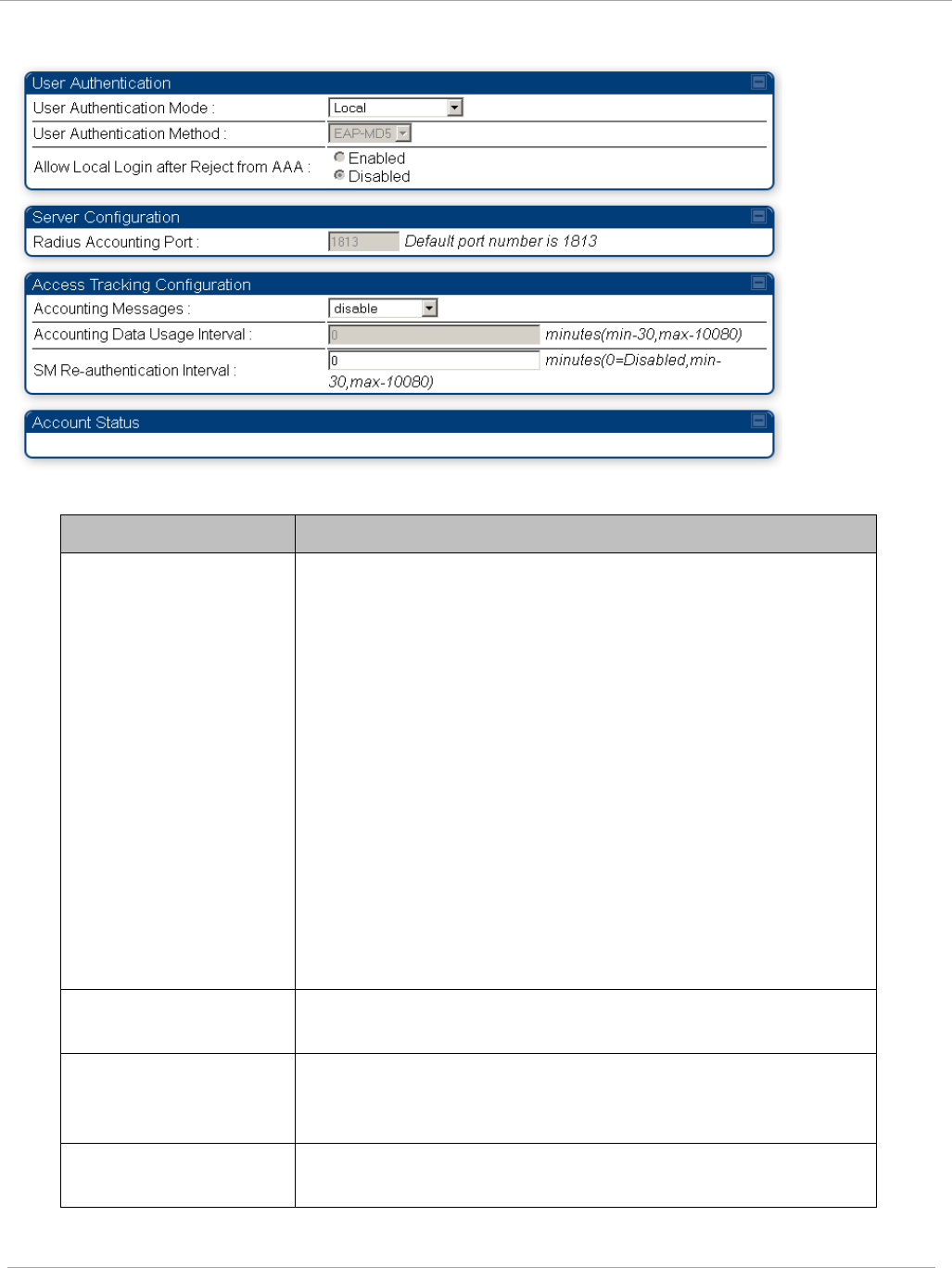
Task 15: Configuring a RADIUS server PMP 450i and PTP 450i Configuration and User
Guide
Figure 68 User Authentication and Access Tracking tab of the AP
Table 61 AP User Authentication and Access Tracking attributes
Attribute Meaning
User Authentication
Mode
• Local: The local SM is checked for accounts. No
centralized
RADIUS
accounting (access control)
is
performed.
• Remote: Authentication by the centralized RADIUS
server
is
required to gain access to the AP. For up to
2
minutes a test pattern is displayed until the server
responds
or
times
out.
• Remote then Local: Authentication using the
centralized
RADIUS
server is attempted. If the server
sends a reject message, then
the
setting of Allow
Local Login after Reject from AAA determines
if
the local user database is checked or not. If the
configured
servers
do
not respond within 2 minutes,
then the local user database
is
used. The successful
login method is displayed in the
navigation
column of
the AP.
User Authentication
Method
The user authentication method employed by the radios is
EAP-MD5.
Allow Local Login
after Reject from AAA
If a user authentication is rejected from the AAA server,
the user is allowed to login locally to the radio’s
management interface.
Radius Accounting
Port
The destination port on the AAA server used for Radius
accounting communication.
pmp-0957 (April 2015) 205

PMP 450i and PTP 450i Configuration and User
Task 15: Configuring a RADIUS server
Attribute Meaning
Accounting Messages
• disable – no accounting messages are sent to the
RADIUS server
• deviceAccess – accounting messages are sent to the
RADIUS server regarding device access (see Table 63).
• dataUsage – accounting messages are sent to the
RADIUS server regarding data usage (see Table 63).
Accounting Data
Usage Interval
The interval for which accounting data messages are sent
from the radio to the RADIUS server. If 0 is configured
for this parameter, no data usage messages are sent.
SM Re-authentication
Interval
The interval for which the SM will re-authenticate to the
RADIUS server.
SM – Technician/Installer/Administrator
Authentication
To control technician, installer, and administrator access to the SM from a centralized
RADIUS server:
Remote access control is enabled only after the SM registers to an AP that
has
Authentication Mode set to RADIUS AAA. Local access control will always be
used
before registration and is used after registration if the AP is not configured
for
RADIUS.
1 Set Authentication Mode on the AP’s Configuration > Security tab to
RADIUS
AAA
(RADIUS)
2 Set User Authentication Mode on the AP’s Account > User
Authentication
and
Access Tracking tab (the tab only appears after the AP is set to AAA
authentication) to Remote or Remote then
Local
.
3 Set User Authentication Mode on the SM’s Account > User Authentication
and Access Tracking tab to Remote or Remote then Local.
•
Local: The local SM is checked for accounts. No centralized
RADIUS
accounting (access control)
is
performed.
•
Remote: Authentication by the centralized RADIUS server
is
required to
gain access to the SM if the SM is registered to an
AP
that has RADIUS
AAA Authentication Mode selected. For up to
2
minutes a test pattern is
displayed until the server responds
or
times
out.
•
Remote then Local: Authentication using the centralized
RADIUS
server is attempted. If the server sends a reject message, then
the
setting of
Allow Local Login after Reject from AAA determines
if
the local user
database is checked or not. If the configured
servers
do
not respond within
2 minutes, then the local user database
is
used. The successful login
method is displayed in the
navigation
column of the SM.
206 pmp-0957 (April 2015)
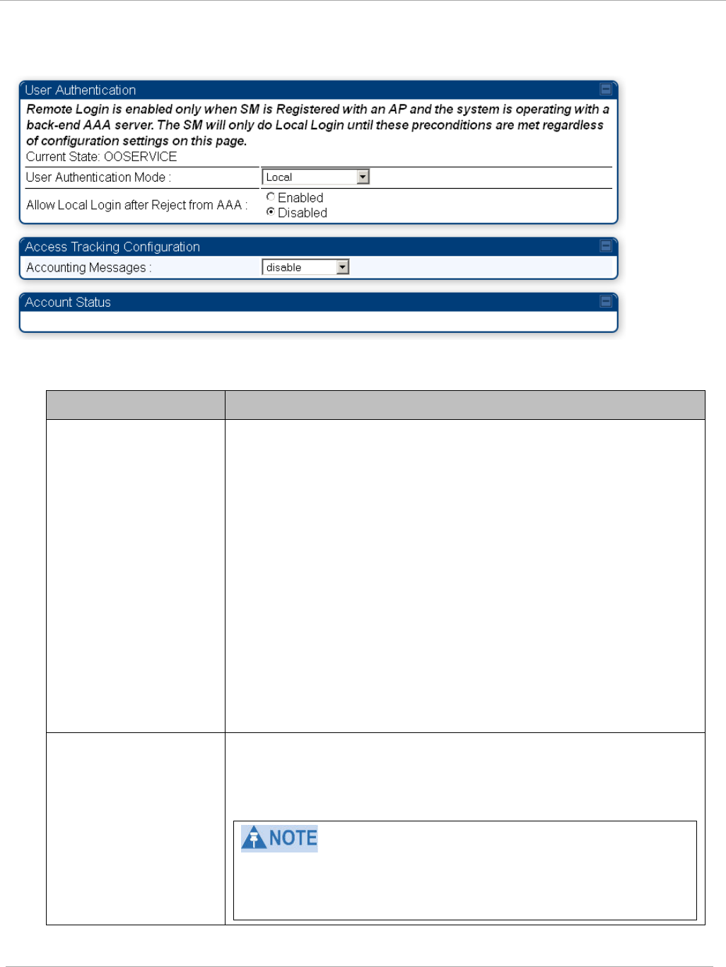
Task 15: Configuring a RADIUS server PMP 450i and PTP 450i Configuration and User
Guide
Figure 69 User Authentication and Access Tracking tab of the SM
Table 62 SM User Authentication and Access Tracking attributes
Attribute Meaning
User Authentication
Mode
•
Local: The local SM is checked for accounts. No
centralized
RADIUS
accounting (access control)
is
performed.
•
Remote: Authentication by the centralized RADIUS server
is
required to gain access to the SM if the SM is registered to
an
AP
that has RADIUS AAA Authentication Mode
selected. For up to
2
minutes a test pattern is displayed until
the server responds
or
times
out.
•
Remote then Local: Authentication using the centralized
RADIUS
server is attempted. If the server sends a reject
message, then
the
setting of Allow Local Login after Reject
from AAA determines
if
the local user database is checked or
not. If the configured
servers
do
not respond within 2
minutes, then the local user database
is
used. The successful
login method is displayed in the
navigation
column of the SM.
Allow Local Login
after Reject from AAA
If a user authentication is rejected from the AAA server, the
user is allowed to login locally to the radio’s management
interface. It is applicable ONLY when the User Authentication
Mode is set to “Remote then Local”.
When the radio User Authentication Mode is set to
“Local” or “Remote”, the Allow Local Login after Reject
from AAA does not any effect.
pmp-0957 (April 2015) 207

PMP 450i and PTP 450i Configuration and User
Task 15: Configuring a RADIUS server
Attribute Meaning
Accounting Messages
• disable – no accounting messages are sent to the RADIUS
server
• deviceAccess – accounting messages are sent to the RADIUS
server regarding device access (see Table 63).
Access
Tracking
To track logon and logoff times on individual radios by technicians, installers, and
administrators, on the AP or SM’s Account > User Authentication and Access
Tracking tab
under
Accounting (Access Tracking) set Accounting Messages to
“deviceAccess”.
Device Access Tracking is enabled separately from User Authentication Mode. A
given AP
or
SM can be configured for both, either, or
neither.
RADIUS Device Data Accounting
PMP 450i systems include support for RADIUS accounting messages for usage-based
billing. This accounting includes indications for subscriber session establishment,
subscriber session disconnection, and bandwidth usage per session for each SM that
connects to the AP. The attributes included in the RADIUS accounting messages are shown
in the table below.
Table 63 Device data accounting RADIUS attributes
Sender Message Attribute Value Description
AP Accounting-
Request
Acct-Status-Type 1 - Start This message is sent
every time a SM
registers with an AP,
and after the SM stats
are cleared.
Acct-Session-Id
Unique per AP session.
Initial value is SM
MAC, and increments
after every start
message sent of an in
session SM.
Event-Timestamp UTC time the event
occurred on the AP
AP Accounting-
Request
Acct-Status-Type 2 - Stop This message is sent
every time a SM
becomes unregistered
with an AP, and when
the SM stats are
cleared.
Acct-Session-Id
Unique per AP session.
Initial value is SM
MAC, and increments
after every start
message sent of an in
session SM.
208 pmp-0957 (April 2015)

Task 15: Configuring a RADIUS server PMP 450i and PTP 450i Configuration and User
Guide
Sender Message Attribute Value Description
Acct-Input-Octets
Sum of the input octets
received at the SM
over regular data VC
and the high priority
data VC (if enabled).
Will not include
broadcast.
Acct-Output-
Octets
Sum of the output
octets sent from the
SM over regular data
VC and the high
priority data VC (if
enabled).
Acct-Input-
Gigawords
Number of times the
Acct-Input-Octets
counter has wrapped
around 2^32 over the
course of the session
Acct-Output-
Gigawords
Number of times the
Acct-Output-Octets
counter has wrapped
around 2^32 over the
course of the session
Acct-Input-
Packets
Sum of unicast and
multicast packets that
are sent to a particular
SM over the regular
data VC and the high
priority data VC (if
enabled). It will not
include broadcast.
Acct-Output-
Packets
Sum of unicast and
multicast packets that
are sent from a
particular SM over the
regular data VC and
the high priority data
VC (if enabled).
Acct-Session-
Time
Uptime of the SM
session.
Acct-Terminate-
Cause
Reason code for
session termination
pmp-0957 (April 2015) 209

PMP 450i and PTP 450i Configuration and User
Task 15: Configuring a RADIUS server
Sender Message Attribute Value Description
AP Accounting-
Request
Acct-Status-Type 3 - Interim-Update This message is sent
periodically per the
operator configuration
on the AP in seconds.
Interim update counts
are cumulative over the
course of the session
Acct-Session-Id
Unique per AP session.
Initial value is SM
MAC, and increments
after every start
message sent of an in
session SM.
Acct-Input-Octets
Sum of the input octets
sent to the SM over
regular data VC and
the high priority data
VC (if enabled). Will
not include broadcast.
Acct-Output-
Octets
Sum of the output
octets set from the SM
over regular data VC
and the high priority
data VC (if enabled).
Acct-Input-
Gigawords
Number of times the
Acct-Input-Octets
counter has wrapped
around 2^32 over the
course of the session
Acct-Output-
Gigawords
Number of times the
Acct-Output-Octets
counter has wrapped
around 2^32 over the
course of the session
Acct-Session-
Time
Uptime of the SM
session.
Acct-Input-
Packets
Sum of unicast and
multicast packets that
are sent to a particular
SM over the regular
data VC and the high
priority data VC (if
enabled). It will not
include broadcast.
210 pmp-0957 (April 2015)
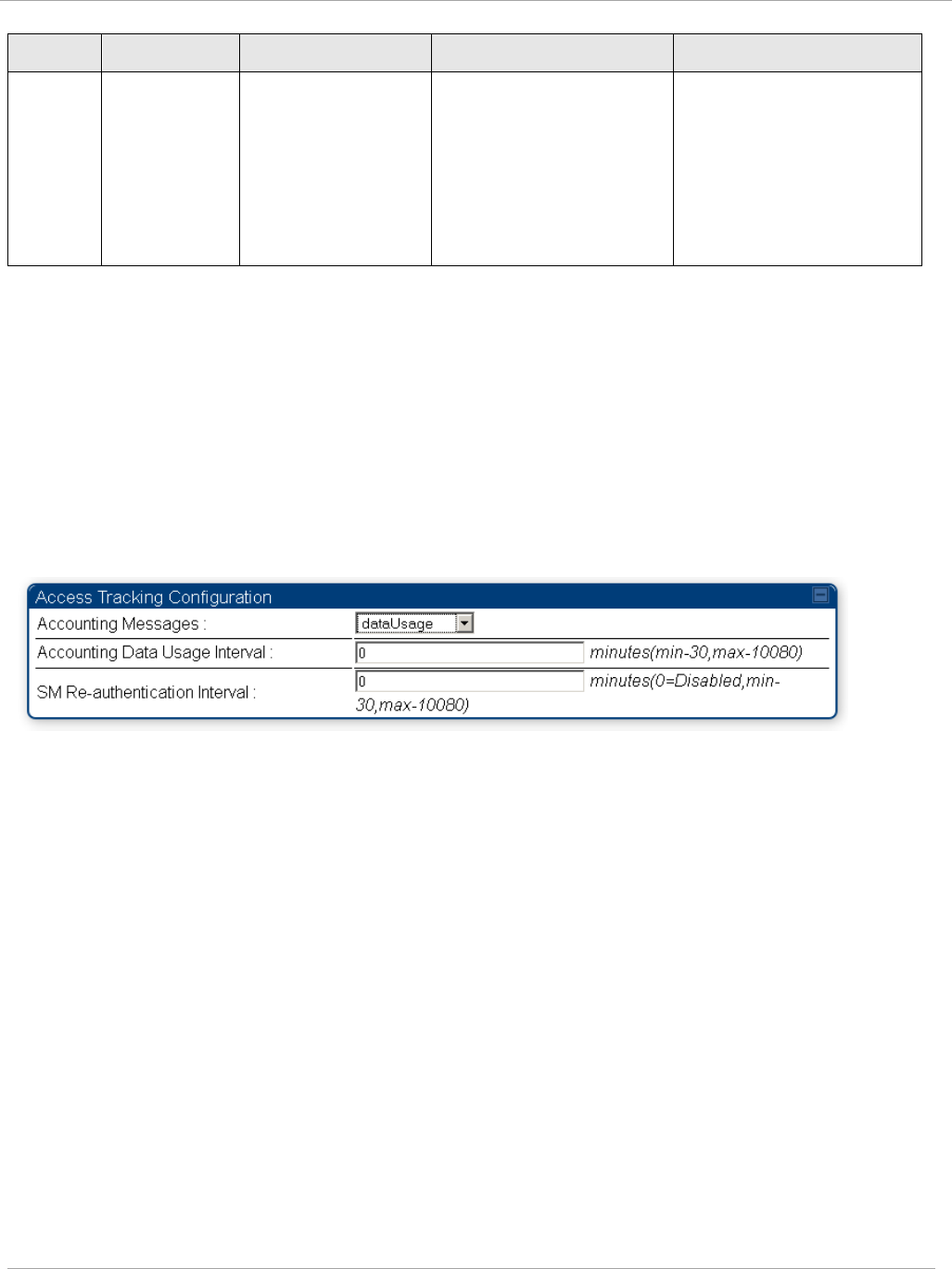
Task 15: Configuring a RADIUS server PMP 450i and PTP 450i Configuration and User
Guide
Sender Message Attribute Value Description
Acct-Output-
Packets
Sum of unicast and
multicast packets that
are sent from a
particular SM over the
regular data VC and
the high priority data
VC (if enabled).
The data accounting configuration is located on the AP’s Accounts => User
Authentication and Access Tracking GUI menu, and the AP’s Authentication Mode
must be set to Radius AAA for the menu to appear. The accounting may be configured via
the AP GUI as shown in the figures below. By default accounting messages are not sent
and the operator has the choice of configuring to send only Device Access accounting
messages (when a user logs in or out of the radio), only Data Usage messages, or both.
When Data Accounting is enabled, the operator must specify the interval of when the data
accounting messages are sent (0 – disabled, or in the range of 30-10080 minutes). The
default interval is 30 minutes.
Figure 70 RADIUS accounting messages configuration
The data accounting message data is based on the SM statistics that the AP maintains, and
these statistics may be cleared on the AP by an operator. If an operator clears these
messages and data accounting is enabled, an accounting stop message is sent followed by
an accounting start message to notify the AAA of the change.
If an operator clears the VC statistics on the device through the management GUI, a
RADIUS stop message and data start message is issued for each device affected. The start
and stop messages will only be sent once every 5 minutes, so if an operator clears these
statistics multiple times within 5 minutes, only one set of data stop/start messages is sent.
This may result in inaccurate data accumulation results.
pmp-0957 (April 2015) 211

PMP 450i and PTP 450i Configuration and User
Task 15: Configuring a RADIUS server
RADIUS Device Re-authentication
PMP 450i systems include support for periodic SM re-authentication in a network without
requiring the SM to re-register (and drop the session). The re-authentication may be
configured to occur in the range of every 30 minutes to weekly.
Figure 71 Device re-authentication configuration
The re-authentication interval is only configurable on the AP. When this feature is enabled,
each SM that enters the network will re-authenticate each the interval time has expired
without dropping the session. The response that the SM receives from the AAA server upon
re-authentication is one of the following:
• Success: The SM continues normal operation
• Reject: The SM de-registers and will attempt network entry again after 1 minute and
then if rejected will attempt re-entry every 15 minutes
• Timeout or other error: The SM remains in session and attempt 5 times to re-
authenticate with the RADIUS-REQUEST message. If these attempts fail, then the SM
will go out of session and proceed to re-authenticate after 5 minutes, then every 15
minutes.
Although re-authentication is an independent feature, it was designed to work alongside
with the RADIUS data usage accounting messages. If a user is over their data usage limit
the network operator can reject the user from staying in the network. Operators may
configure the RADIUS ‘Reply-Message’ attribute with an applicable message (i.e. “Data
Usage Limit Reached”) that is sent to the subscriber module and displayed on the general
page.
212 pmp-0957 (April 2015)

PMP 450i and PTP 450i Configuration and User Guid
: Glossary
Appendix A : Glossary
Table 64 Glossary
Term Definition
10Base-T Technology in Ethernet communications that can deliver 10 Mb of
data across 328 feet (100 meters) of CAT 5 cable.
169.254.0.0 Gateway IP address default in Cambium fixed wireless broadband
IP network modules.
169.254.1.1 IP address default in Cambium fixed wireless broadband IP
network modules.
255.255.0.0 Subnet mask default in Cambium fixed wireless broadband IP
network modules and in Microsoft and Apple operating systems.
802.3 An IEEE standard that defines the contents of frames that are
transferred through Ethernet connections. Each of these frames
contains a preamble, the address to which the frame is sent, the
address that sends the frame, the length of the data to expect, the
data, and a checksum to validate that no contents were lost.
802.11 The IEEE standard for wireless local area networks.
802.15 The IEEE standard for wireless personal area networks.
Access Point
Cluster
Two to six Access Point Modules that together distribute network
or Internet services to a community of subscribers. Each Access
Point Module covers a 60° or 90° sector. This cluster covers as
much as 360°. Also known as AP cluster.
Access Point
Module
Also known as AP. One module that distributes network or Internet
services in a 60° or 90° sector.
ACT/4 Second-from-left LED in the module. In the operating mode, this
LED is lit when data activity is present on the Ethernet link.
Activate To provide feature capability to a module, but not to
enable
(turn
on) the feature in the module. See also Enable.
Address
Resolution
Protocol
Protocol defined in RFC 826 to allow a network element to
correlate a host IP address to the Ethernet address of the host. See
http://www.faqs.org/rfcs/rfc826.html.
Aggregate
Throughput
The sum of the throughputs in the uplink and the downlink.
AP Access Point Module. One module that distributes network or
Internet services to subscriber modules.
pmp-0957 (April 2015) 213

PMP 450i and PTP 450i Configuration and User Guid
: Glossary
Term Definition
APs MIB Management Information Base file that defines objects that are
specific to the Access Point Module. See also Management
Information Base.
ARP Address Resolution Protocol. A protocol defined in RFC 826 to
allow a network element to correlate a host IP address to the
Ethernet address of the host. See
http://www.faqs.org/rfcs/rfc826.html.
ASN.1 Abstract Syntax Notation One language. The format of the text files
that compose the Management Information Base.
Attenuation Reduction of signal strength caused by the travel from the
transmitter to the receiver, and caused by any object between. In
the absence of objects between, a signal that has a short
wavelength experiences a high degree of attenuation nevertheless.
BER Bit Error Rate. The ratio of incorrect data received to correct data
received.
Bit Error Rate Ratio of incorrect data received to correct data received.
Box MIB Management Information Base file that defines module-level
objects. See also Management Information Base.
Bridge Network element that uses the physical address (not the logical
address) of another to pass data. The bridge passes the data to
either the destination address, if found in the simple routing table,
or to all network segments other than the one that transmitted the
data. Modules are Layer 2 bridges except that, where NAT is
enabled for an SM, the SM is a Layer 3 switch. Compare to Switch
and Router, and see also NAT.
Bridge Entry
Timeout Field
Value that the operator sets as the maximum interval for no activity
with another module, whose MAC address is the Bridge Entry. This
interval should be longer than the ARP (Address Resolution
Protocol) cache timeout of the router that feeds the network.
Buckets Theoretical data repositories that can be filled at preset rates or
emptied when preset conditions are experienced, such as when
data is transferred.
Burst Preset amount limit of data that may be continuously transferred.
C/I Ratio Ratio of intended signal (carrier) to unintended signal
(interference) received.
Carrier-to-
interference
Ratio
Ratio of intended reception to unintended reception.
214 pmp-0957 (April 2015)

PMP 450i and PTP 450i Configuration and User Guid
: Glossary
Term Definition
CarSenseLost
Field
This field displays how many carrier sense lost errors occurred on
the Ethernet controller.
CAT 5 Cable Cable that delivers Ethernet communications from module to
module. Later modules auto-sense whether this cable is wired in a
straight-through or crossover scheme.
CIR Committed Information Rate. For an SM or specified group of
SMs, a level of bandwidth that can be guaranteed to never fall
below a specified minimum (unless oversubscribed). In the
Cambium implementation, this is controlled by the Low Priority
Uplink CIR, Low Priority Downlink CIR, High Priority Uplink CIR,
and High Priority Downlink CIR parameters.
CLIP Cassegrain Lens for Improved Performance
Cluster
Management
Module
Module that provides power, GPS timing, and networking
connections for an AP cluster. Also known as CMM.
CMM Cluster Management Module. A module that provides power, GPS
timing, and networking connections for an Access Point cluster.
CodePoint See DiffServ.
Color Code Field Module parameter that identifies the other modules with which
communication is allowed. The range of valid values is 0 to 255.
Community
String Field
Control string that allows a network management station to access
MIB information about the module.
Country Code A parameter that offers multiple fixed selections, each of which
automatically implements frequency band range restrictions for the
selected country. Units shipped to countries other than the United
States must be configured with the corresponding Region Code and
Country Code to comply with local regulatory requirements.
CRCError Field This field displays how many CRC errors occurred on the Ethernet
controller.
Data Encryption
Standard
Over-the-air link option that uses secret 56-bit keys and 8 parity
bits. Data Encryption Standard (DES) performs a series of bit
permutations, substitutions, and recombination operations on
blocks of data.
Demilitarized
Zone
Internet Protocol area outside of a firewall. Defined in RFC 2647.
See http://www.faqs.org/rfcs/rfc2647.html.
DES Data Encryption Standard. An over-the-air link option that uses
secret 56-bit keys and 8 parity bits. DES performs a series of bit
permutations, substitutions, and recombination operations on
blocks of data.
pmp-0957 (April 2015) 215

PMP 450i and PTP 450i Configuration and User Guid
: Glossary
Term Definition
Desensed Received an undesired signal that was strong enough to make the
module insensitive to the desired signal.
DFS See Dynamic Frequency Selection
DHCP Dynamic Host Configuration Protocol, defined in RFC 2131.
Protocol that enables a device to be assigned a new IP address and
TCP/IP parameters, including a default gateway, whenever the
device reboots. Thus DHCP reduces configuration time, conserves
IP addresses, and allows modules to be moved to a different
network within the system. See
http://www.faqs.org/rfcs/rfc2131.html. See also Static IP Address
Assignment.
DiffServ Differentiated Services, consistent with RFC 2474. A byte in the
type of service (TOS) field of packets whose values correlates to the
channel on which the packet should be sent. The value is a numeric
code point. Cambium modules map each of 64 code points to values
of 0 through 7. Three of these code points have fixed values, and
the remaining 61 are settable. Values of 0 through 3 map to the
low-priority channel; 4 through 7 to the high-priority channel. The
mappings are the same as 802.1p VLAN priorities. (However,
configuring DiffServ does not automatically enable the VLAN
feature.) Among the settable parameters, the values are set in the
AP for all downlinks within the sector and in the SM for each
uplink.
Disable To turn off a feature in the module after both the feature activation
file has
activated
the module to use the feature and the operator
has
enabled
the feature in the module. See also Activate and
Enable.
DMZ Demilitarized Zone as defined in RFC 2647. An Internet Protocol
area outside of a firewall. See
http://www.faqs.org/rfcs/rfc2647.html.
Dynamic
Frequency
Selection
A requirement in certain countries and regions for systems to
detect
interference from other systems, notably radar systems, and to
avoid co-channel operation with these systems.
Dynamic Host
Configuration
Protocol
See DHCP.
Electronic Serial
Number
Hardware address that the factory assigns to the module for
identification in the Data Link layer interface of the Open Systems
Interconnection system. This address serves as an electronic serial
number. Same as MAC Address.
216 pmp-0957 (April 2015)

PMP 450i and PTP 450i Configuration and User Guid
: Glossary
Term Definition
Enable To turn on a feature in the module after the feature activation file
has
activated
the module to use the feature. See also Activate.
ESN Electronic Serial Number. The hardware address that the factory
assigns to the module for identification in the Data Link layer
interface of the Open Systems Interconnection system. This
address serves as an electronic serial number. Same as MAC
Address.
EthBusErr Field This field displays how many Ethernet bus errors occurred on the
Ethernet controller.
Ethernet
Protocol
Any of several IEEE standards that define the contents of frames
that are transferred from one network element to another through
Ethernet connections.
ETSI European Telecommunications Standards Institute
Fade Margin The difference between strength of the received signal and the
strength that the receiver requires for maintaining a reliable link. A
higher fade margin is characteristic of a more reliable link.
Standard operating margin.
FCC Federal Communications Commission of the U.S.A.
Field-
programmable
Gate Array
Array of logic, relational data, and wiring data that is factory
programmed and can be reprogrammed.
File Transfer
Protocol
Utility that transfers of files through TCP (Transport Control
Protocol) between computing devices that do not operate on the
same platform. Defined in RFC 959. See
http://www.faqs.org/rfcs/rfc959.html.
FPGA Field-programmable Gate Array. An array of logic, relational data,
and wiring data that is factory programmed and can be
reprogrammed.
Frame Timing
Pulse Gated
Field
Toggle parameter that prevents or allows the module to continue to
propagate GPS sync timing when the module no longer receives the
timing.
Free Space Path
Loss
Signal attenuation that is naturally caused by atmospheric
conditions and by the distance between the antenna and the
receiver.
Fresnel Zone Space in which no object should exist that can attenuate, diffract,
or reflect a transmitted signal before the signal reaches the target
receiver.
pmp-0957 (April 2015) 217

PMP 450i and PTP 450i Configuration and User Guid
: Glossary
Term Definition
FTP File Transfer Protocol, defined in RFC 959. Utility that transfers of
files through TCP (Transport Control Protocol) between computing
devices that do not operate on the same platform. See
http://www.faqs.org/rfcs/rfc959.html.
Global
Positioning
System
Network of satellites that provides absolute time to networks on
earth, which use the time signal to synchronize transmission and
reception cycles (to avoid interference) and to provide reference
for troubleshooting activities.
GPS Global Positioning System. A network of satellites that provides
absolute time to networks on earth, which use the time signal to
synchronize transmission and reception cycles (to avoid
interference) and to provide reference for troubleshooting
activities.
GPS/3 Third-from-left LED in the module. In the operating mode for an
Access Point Module, this LED is continuously lit as the module
receives sync pulse. In the operating mode for a Subscriber, this
LED flashes on and off to indicate that the module is not registered.
GUI Graphical user interface.
High-priority
Channel
Channel that supports low-latency traffic (such as Voice over IP)
over low-latency traffic (such as standard web traffic and file
downloads). To recognize the latency tolerance of traffic, this
channel reads the IPv4 Type of Service DiffServ Control Point
(DSCP) bits. Enabling the high-priority channel reduces the
maximum number of SMs that can be served in the sector.
HTTP Hypertext Transfer Protocol, used to make the Internet resources
available on the World Wide Web. Defined in RFC 2068. See
http://www.faqs.org/rfcs/rfc2068.html.
HTTPS Hypertext Transfer Protocol Secure (HTTPS)
ICMP Internet Control Message Protocols defined in RFC 792, used to
identify Internet Protocol (IP)-level problems and to allow IP links
to be tested. See http://www.faqs.org/rfcs/rfc792.html.
indiscards count
Field
How many inbound packets were discarded without errors that
would have prevented their delivery to a higher-layer protocol.
(Some of these packets may have been discarded to increase buffer
space.)
inerrors count
Field
How many inbound packets contained errors that prevented their
delivery to a higher-layer protocol.
innucastpkts
count Field
How many inbound non-unicast (subnetwork-broadcast or
subnetwork-multicast) packets were delivered to a higher-layer
protocol.
218 pmp-0957 (April 2015)

PMP 450i and PTP 450i Configuration and User Guid
: Glossary
Term Definition
inoctets count
Field
How many octets were received on the interface, including those
that deliver framing information.
Intel A registered trademark of Intel Corporation.
inucastpkts
count Field
How many inbound subnetwork-unicast packets were delivered to a
higher-layer protocol.
inunknownprotos
count Field
How many inbound packets were discarded because of an unknown
or unsupported protocol.
IP Internet Protocol defined in RFC 791. The Network Layer in the
TCP/IP protocol stack. This protocol is applied to addressing,
routing, and delivering, and re-assembling data packets into the
Data Link layer of the protocol stack. See
http://www.faqs.org/rfcs/rfc791.html.
IP Address 32-bit binary number that identifies a network element by both
network and host. See also Subnet Mask.
IPv4 Traditional version of Internet Protocol, which defines 32-bit fields
for data transmission.
ISM Industrial, Scientific, and Medical Equipment radio frequency
band, in the 900-MHz, 2.4-GHz, and 5.8-GHz ranges.
L2TP over IPSec Level 2 Tunneling Protocol over IP Security. One of several virtual
private network (VPN) implementation schemes. Regardless of
whether Subscriber Modules have the Network Address
Translation feature (NAT) enabled, they support VPNs that are
based on this protocol.
Late Collision
Field
This field displays how many late collisions occurred on the
Ethernet controller. A normal collision occurs during the first 512
bits of the frame transmission. A collision that occurs after the first
512 bits is considered a late collision. A late collision is a serious
network problem because the frame being transmitted is
discarded. A late collision is most commonly caused by a mismatch
between duplex configurations at the ends of a link segment.
Latency
Tolerance
Acceptable tolerance for delay in the transfer of data to and from a
module.
LBT Listen Before Talk (LBT) or sometimes called Listen Before
Transmit is a technique used in radio communications whereby a
radio transmitters first sense its radio environment before it starts
a transmission.
Line of Sight Wireless path (not simply visual path) direct from module to
module. The path that results provides both ideal aim and an ideal
Fresnel zone.
pmp-0957 (April 2015) 219

PMP 450i and PTP 450i Configuration and User Guid
: Glossary
Term Definition
LNK/5 Furthest left LED in the module. In the operating mode, this LED is
continuously lit when the Ethernet link is present. In the aiming
mode for a Subscriber Module, this LED is part of a bar graph that
indicates the quality of the RF link.
Logical Unit ID Final octet of the 4-octet IP address of the module.
LOS Line of sight. The wireless path (not simply visual path) direct from
module to module. The path that results provides both ideal aim
and an ideal Fresnel zone.
LUID Logical Unit ID. The final octet of the 4-octet IP address of the
module.
MAC Address Media Access Control address. The hardware address that the
factory assigns to the module for identification in the Data Link
layer interface of the Open Systems Interconnection system. This
address serves as an electronic serial number.
Management
Information Base
Space that allows a program (agent) in the network to relay
information to a network monitor about the status of defined
variables (objects).
Maximum
Information Rate
(MIR)
The cap applied to the bandwidth of an SM or specified group of
SMs. In the Cambium implementation, this is controlled by the
Sustained Uplink Data Rate, Uplink Burst Allocation, Sustained
Downlink Data Rate, and Downlink Burst Allocation parameters.
Media Access
Control Address
Hardware address that the factory assigns to the module for
identification in the Data Link layer interface of the Open Systems
Interconnection system. This address serves as an electronic serial
number.
MIB Management Information Base. Space that allows a program
(agent) in the network to relay information to a network monitor
about the status of defined variables (objects).
MIR See Maximum Information Rate.
NAT Network Address Translation defined in RFC 1631. A scheme that
isolates Subscriber Modules from the Internet. See
http://www.faqs.org/rfcs/rfc1631.html.
NEC National Electrical Code. The set of national wiring standards that
are enforced in the U.S.A.
220 pmp-0957 (April 2015)

PMP 450i and PTP 450i Configuration and User Guid
: Glossary
Term Definition
NetBIOS Protocol defined in RFC 1001 and RFC 1002 to support an
a
pplications programming interface in TCP/IP. This interface allows
a computer to transmit and receive data with another host
computer on the network. RFC 1001 defines the concepts and
methods. RFC 1002 defines the detailed specifications. See
http://www.faqs.org/rfcs/rfc1001.html and
http://www.faqs.org/rfcs/rfc1002.html.
Network Address
Translation
Scheme that defines the Access Point Module as a proxy server to
isolate registered Subscriber Modules from the Internet. Defined in
RFC 1631. See http://www.faqs.org/rfcs/rfc1631.html.
Network
Management
Station
See NMS.
NMS Network Management Station. A monitor device that uses Simple
Network Management Protocol (SNMP) to control, gather, and
report information about predefined network variables (objects).
See also Simple Network Management Protocol.
Object Network variable that is defined in the Management Information
Base.
outdiscards
count Field
How many outbound packets were discarded without errors that
would have prevented their transmission. (Some of these packets
may have been discarded to increase buffer space.)
outerrrors count
Field
How many outbound packets contained errors that prevented their
transmission.
outnucastpkts
count Field
How many packets for which the higher-level protocols requested
transmission to a non-unicast (subnetwork-broadcast or
subnetwork-multicast) address. The number includes those that
were discarded or not sent.
outoctets count
Field
How many octets were transmitted out of the interface, including
those that deliver framing information.
outucastpkts
count Field
How many packets for which the higher-level protocols requested
transmission to a subnetwork-unicast address. The number
includes those that were discarded or not sent.
Override Plug Device that enables the operator to regain control of a module that
has been locked by the No Remote Access feature, the 802.3 Link
Disable feature, or a password or IP address that cannot be
recalled. This device can be either fabricated on site or ordered.
PMP See Point-to-Multipoint Protocol.
pmp-0957 (April 2015) 221

PMP 450i and PTP 450i Configuration and User Guid
: Glossary
Term Definition
Point-to-
Multipoint
Protocol
Defined in RFC 2178, which specifies that data that originates from
a central network element can be received by all other network
elements, but data that originates from a non-central network
element can be received by only the central network element. See
http://www.faqs.org/rfcs/rfc2178.html. Also referenced as PMP.
PPPoE Point to Point Protocol over Ethernet. Supported on SMs for
operators who use PPPoE in other parts of their network
operators who want to deploy PPPoE to realize per-subscriber
authentication, metrics, and usage control.
PPS Packet Per Second
PPTP Point to Point Tunneling Protocol. One of several virtual private
network implementations. Regardless of whether the Network
Address Translation (NAT) feature enabled, Subscriber Modules
support VPNs that are based on this protocol.
Protective Earth Connection to earth (which has a charge of 0 volts). Also known as
ground.
Proxy Server Network computer that isolates another from the Internet. The
proxy server communicates for the other computer, and sends
replies to only the appropriate computer, which has an IP address
that is not unique or not registered.
PTMP See Point-to-Multipoint Protocol.
Quick Start Interface page that requires minimal configuration for initial
module operation.
Radio Signal
Strength
Indicator
Relative measure of the strength of a received signal. An
acceptable link displays an Radio Signal Strength Indicator (RSSI)
value of greater than 700.
Recharging Resumed accumulation of data in available data space (buckets).
See Buckets.
Reflection Change of direction and reduction of amplitude of a signal that
encounters an object larger than the wavelength. Reflection may
cause an additional copy of the wavelength to arrive after the
original, unobstructed wavelength arrives. This causes partial
cancellation of the signal and may render the link unacceptable.
However, in some instances where the direct signal cannot be
received, the reflected copy may be received and render an
otherwise unacceptable link acceptable.
222 pmp-0957 (April 2015)

PMP 450i and PTP 450i Configuration and User Guid
: Glossary
Term Definition
Region Code A parameter that offers multiple fixed selections, each of which
automatically implements frequency band range restrictions for
the selected region. Units shipped to regions other than the United
States must be configured with the corresponding Region Code to
comply with local regulatory requirements.
Registrations
MIB
Management Information Base file that defines registrations for
global items such as product identities and product components.
See also Management Information Base.
RetransLimitExp
Field
This field displays how many times the retransmit limit has expired.
RF Radio frequency. How many times each second a cycle in the
antenna occurs, from positive to negative and back to positive
amplitude.
RJ-11 Standard cable that is typically used for telephone line or modem
connection.
RJ-45 Standard cable that is typically used for Ethernet connection. This
cable may be wired as straight-through or as crossover. Later
modules auto-sense whether the cable is straight-through or
crossover.
Router Network element that uses the logical (IP) address of another to
pass data to only the intended recipient. Compare to Switch and
Bridge.
RSSI Radio Signal Strength Indicator. A relative measure of the strength
of a received signal. An acceptable link displays an RSSI value of
greater than 700.
RTG Receive/Transmit Transition Gap. A gap between the uplink burst
and the subsequent downlink burst in a TDD transceiver. During
RTG, AP/BHM switches from receive to transmit mode and
SMs/BHS switch from transmit to receive mode.
RxBabErr Field This field displays how many receiver babble errors occurred.
RxOverrun Field This field displays how many receiver overrun errors occurred on
the Ethernet controller.
Secure Shell A trademark of SSH Communications Security.
Self-interference Interference with a module from another module in the same
network.
pmp-0957 (April 2015) 223

PMP 450i and PTP 450i Configuration and User Guid
: Glossary
Term Definition
SES/2 Third-from-right LED in the module. In the Access Point Module,
this LED is unused. In the operating mode for a Subscriber Module,
this LED flashes on and off to indicate that the module is not
registered. In the aiming mode for a Subscriber Module, this LED
is part of a bar graph that indicates the quality of the RF link.
Simple Network
Management
Protocol
Standard that is used for communications between a program
(agent) in the network and a network management station
(monitor). Defined in RFC 1157. See
http://www.faqs.org/rfcs/rfc1157.html.
SM Customer premises equipment (CPE) device that extends network
or Internet services by communication with an Access Point
Module or an Access Point cluster.
SM MIB Management Information Base file that defines objects that are
specific to the Subscriber Module. See also Management
Information Base.
SNMP See Simple Network Management Protocol, defined in RFC 1157.
SNMPv3 SNMP version 3
SNMP Trap Capture of information that informs the network monitor through
Simple Network Management Protocol of a monitored occurrence
in the module.
Static IP Address
Assignment
Assignment of Internet Protocol address that can be changed only
manually. Thus static IP address assignment requires more
configuration time and consumes more of the available IP
addresses than DHCP address assignment does. RFC 2050 provides
guidelines for the static allocation of IP addresses. See
http://www.faqs.org/rfcs/rfc2050.html. See also DHCP.
Subnet Mask 32-bit binary number that filters an IP address to reveal what part
identifies the network and what part identifies the host. The
number of subnet mask bits that are set to 1 indicates how many
leading bits of the IP address identify the network. The number of
subnet mask bits that are set 0 indicate how many trailing bits of
the IP address identify the host.
Subscriber
Module
Customer premises equipment (CPE) device that extends network
or Internet services by communication with an Access Point
Module or an Access Point cluster.
Sustained Data
Rate
Preset rate limit of data transfer.
Switch Network element that uses the port that is associated with the
physical address of another to pass data to only the intended
recipient. Compare to Bridge and Router.
224 pmp-0957 (April 2015)

PMP 450i and PTP 450i Configuration and User Guid
: Glossary
Term Definition
SYN/1 Second-from-right LED in the module. In the Access Point Module
or in a registered Subscriber, this LED is continuously lit to
indicate the presence of sync. In the operating mode for a
Subscriber Module, this LED flashes on and to indicate that the
module is not registered.
Sync GPS (Global Positioning System) absolute time, which is passed
from one module to another. Sync enables timing that prevents
modules from transmitting or receiving interference. Sync also
provides correlative time stamps for troubleshooting efforts.
TCP Alternatively known as Transmission Control Protocol or Transport
Control Protocol. The Transport Layer in the TCP/IP protocol stack.
This protocol is applied to assure that data packets arrive at the
target network element and to control the flow of data through the
Internet. Defined in RFC 793. See
http://www.faqs.org/rfcs/rfc793.html.
TDD Time Division Duplexing. Synchronized data transmission with
some time slots allocated to devices transmitting on the uplink and
some to the device transmitting on the downlink.
telnet Utility that allows a client computer to update a server. A firewall
can prevent the use of the telnet utility to breach the security of
the server. See http://www.faqs.org/rfcs/rfc818.html,
http://www.faqs.org/rfcs/rfc854.html and
http://www.faqs.org/rfcs/rfc855.html.
Textual
Conventions MIB
Management Information Base file that defines system-specific
textual conventions. See also Management Information Base.
Tokens Theoretical amounts of data. See also Buckets.
TOS 8-bit field in that prioritizes data in a IP transmission. See
http://www.faqs.org/rfcs/rfc1349.html.
TTG Transmit/receive Transition Gap. A gap between the downlink burst
and the subsequent uplink burst in a TDD transceiver. During TTG,
AP/BHM switches from transmit to receive mode and SMs/BHS
switch from receive to transmit mode.
TxUnderrun
Field
This field displays how many transmission-underrun errors
occurred on the Ethernet controller.
UDP User Datagram Protocol. A set of Network, Transport, and Session
Layer protocols that RFC 768 defines. These protocols include
checksum and address information but does not retransmit data or
process any errors. See http://www.faqs.org/rfcs/rfc768.html.
udp User-defined type of port.
pmp-0957 (April 2015) 225

PMP 450i and PTP 450i Configuration and User Guid
: Glossary
Term Definition
U-NII Unlicensed National Information Infrastructure radio frequency
band, in the 5.1-GHz through 5.8-GHz ranges.
VID VLAN identifier. See also VLAN.
VLAN Virtual local area network. An association of devices through
software that contains broadcast traffic, as routers would, but in
the switch-level protocol.
VPN Virtual private network for communication over a public network.
One typical use is to connect remote employees, who are at home
or in a different city, to their corporate network over the Internet.
Any of several VPN implementation schemes is possible. SMs
support L2TP over IPSec (Level 2 Tunneling Protocol over IP
Security) VPNs and PPTP (Point to Point Tunneling Protocol) VPNs,
regardless of whether the Network Address Translation (NAT)
feature enabled.
226 pmp-0957 (April 2015)

PMP 450i and PTP 450i Configuration and User Guid
: FCC and IC approved antennas
Appendix B : FCC and IC approved antennas
Table 65 FCC and IC approved antennas list
Description Gain
(dBi)
Frequency band
4.9
GHz
5.8
GHz
Directional antennas
PMP450i/PTP450i Integrated
Directional (5092HH) 23
PMP450i/PTP450i Integrated Small
Form Factor Directional (5096HH) 17
MARS 2 ft flat plate
MA-WA56-DP-28N
28.5
28
GABRIEL 4ft Standard Dual
QuickFire Parabolic QFD4-49-N 33.7
GABRIEL 6ft Standard QuickFire
Parabolic QF6-49-N 37.2
ANDREWS 4ft parabolic antenna
PX4F-52-N7A/A
34.9
35.3
ANDREWS 6 ft Parabolic Dual
Polarised PX6F-52-N7A/A 38.1
Sector antennas
PMP450i Integrated 90° sector 16.0
MARS flat plate 90° sector 16.0
LAIRD 90° sector antenna 17.0
Omni antennas
KPPA omni antenna
5.7-DPOMA 13.0
pmp-0957 (April 2015) 227