Cambium Networks 50450I Wireless Ethernet Bridge, Dual Channel OFDM MIMO Combination Access Point, Subscriber Station and Point to Point Equipment User Manual PMP PTP 450i Series User Guide
Cambium Networks Limited Wireless Ethernet Bridge, Dual Channel OFDM MIMO Combination Access Point, Subscriber Station and Point to Point Equipment PMP PTP 450i Series User Guide
Contents
- 1. Installation Guide
- 2. User Guide Part 1
- 3. User Guide Part 2
- 4. User Guide Part 3
- 5. User Guide Part 4
- 6. User Guide Part 5
- 7. User Guide Part 6
- 8. User Guide Part 7
- 9. Exhibit D Users Manual per 2 1033 b3
- 10. User Manual - Part 1
- 11. User Manual - Part 2
- 12. User Manual - Part 3
- 13. User Manual - Part 4
- 14. Users Manual - Part 5
- 15. Users Manual - Part 6
- 16. User Manual
User Guide Part 6

Page 7-176
Syslog event logging
Following events are logged in syslog as explained in Table 136.
Table 136
Syslog parameters
Attribute
Meaning
Timestamp All syslog messages captured from the radio have a timestamp.
Configuration
Changes
This includes any device setting that has changed and includes the old
or new parameter value, including the device reboots.
User Login and
Logout Syslog records each user login and logout, with username.
Add or Delete of user
accounts through
GUI and SNMP
Syslog captures any user accounts that are added or deleted.
Spectrum Analysis Syslog records a message every time Spectrum Analysis runs.
Note
Since the AP/BHM must be set to a SM/BHS for Spectrum
Analysis, syslog messages are not reported from the radio
until the scan is done and the radio mode is switched back
to AP/BHM.
Link Test Syslog records a message every time a Link Test is run.
Clear Statistics Syslog sends a message when Statistics are cleared. This is done
individually for each statistics page that is cleared.
SM Register or De-
register Syslog records a message when a SM registers or deregisters.
BHS Connect or
Disconnect Syslog records a message when a BHS connects or disconnects.
Configuring system logging
To configure system logging, select the menu option
Configuration >
Syslog
.
Syslog page of AP/BHM
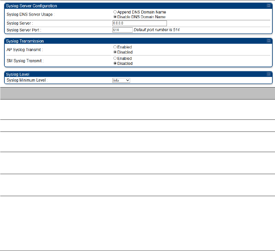
The Syslog Configuration page for AP/BHM is shown in Table 137.
Chapter 7: Configuration Configuring syslog
Page 7-177
Table 137
Syslog Configuration attributes - AP
Attribute
Meaning
Syslog DNS Server Usage
To configure the AP/BHM to append or not append the DNS server
name to the syslog server name.
Syslog Server The dotted decimal or DNS name of the syslog server address.
Syslog Server Port The syslog server port (default 514) to which syslog messaging is
sent.
AP Syslog Transmit
Or BHM Syslog Transmit When enabled, syslog messages are sent from the AP/BHM.
SM Syslog Transmit
Or BHS Syslog Transmit
When enabled, syslog messages are sent from all the registered
SMs/BHS, unless they are individually set to override this.
Syslog Minimum Level
This provides a selection for the minimum syslog message severity
that is sent to the syslog server. Values range from fatal (highest
severity and least verbose) to info (lowest severity, maximum
verbosity).
For example: If the Syslog Minimum Level is set to notice, then only
messages with severity notice and above are sent.
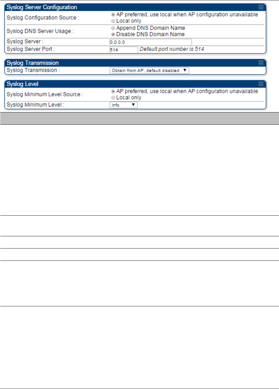
Syslog page of SM
To configure system logging, select the menu option
Configuration > Syslog
. The Syslog
Configuration page is shown in Table 138.
Chapter 7: Configuration Configuring syslog
Page 7-178
Table 138
Syslog Configuration attributes - SM
Attribute
Meaning
Syslog Configuration
Source
This control determines whether the SM will attempt to use the syslog
server definition from the AP, or whether it will use a local server
definition.
When set to
AP preferred, use local when AP configuration unavailable
,
and if the SM can register with an AP, then it uses the syslog server
defined on that AP. If the SM cannot register then it will syslog to its
locally defined syslog server through its wired connection, if any.
When set to
Local only
the SM ignores the AP’s definition of the syslog
server and allows the syslog server to be configured individually for
each SM.
Syslog DNS Server
Usage
To configure the SM to append or not the DNS server name to the
syslog server name.
Syslog Server The dotted decimal or DNS name of the syslog server address.
Syslog Server Port The syslog server port (default 514) to which syslog messaging is sent.
Syslog Transmission Controls the SMs ability to transmit syslog messages. When set to
“Learn from AP” the AP will control whether this SM transmits syslog
messages. When set to “enable” or “disable” the SM will control
whether it sends syslog messages. This allows an operator to override
the AP settings for individual SMs in a sector.
Syslog Minimum
Level Source
This control determines whether the SM attempts to use the minimum
syslog level defined by the AP, or whether it uses a local defined value
using the “Syslog Minimum Level” parameter.
When set to “AP preferred, use local when AP configuration
unavailable”, and if the SM can register with an AP, then it uses the
Syslog Minimum Level defined on that AP. If the SM cannot register
then it uses its own Syslog Minimum Level setting.
When set to “Local only” the SM will always use its own Syslog
Minimum Level setting and ignores the AP’s setting.
Chapter 7: Configuration Configuring syslog
Page 7-179
Syslog Minimum
Level
This provides a selection for the minimum syslog message severity that
is sent to the syslog server. Values range from fatal (highest severity and
least verbose) to info (lowest severity, maximum verbosity).
For example: If the Syslog Minimum Level is set to notice, then only
messages with severity notice and above are sent.
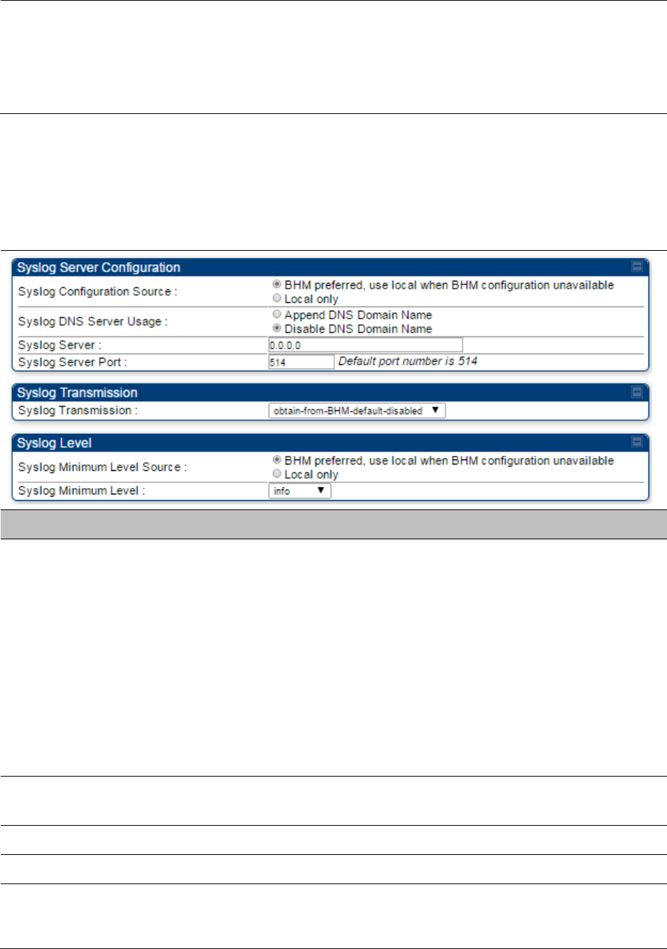
Syslog page of BHS
The Syslog Configuration page is shown in Table 139.
Table 139
Syslog Configuration attributes - BHS
Attribute
Meaning
Syslog Configuration
Source
This control determines whether the BHS will attempt to use the syslog
server definition from the BHM, or whether it will use a local server
definition.
• When set to
BHM preferred, use local when BHM configuration
unavailable
, and if the BHS can register with a BHM, then it uses the
syslog server defined on that BHM. If the BHS cannot register then it
will syslog to its locally defined syslog server through its wired
connection, if any.
• When set to
Local only
the BHS ignores the BHM’s definition of the
syslog server and allows the syslog server to be configured
individually for each BHS.
Syslog DNS Server
Usage
To configure the BHS to append or not to append the DNS server name
to the syslog server name.
Syslog Server The dotted decimal or DNS name of the syslog server address.
Syslog Server Port The syslog server port (default 514) to which syslog messaging is sent.
Syslog Transmission Controls the BHSs ability to transmit syslog messages. When set to
Learn from BHM
the BHM will control whether this BHS transmits
syslog messages. When set to enable or disable the BHS will control

Chapter 7: Configuration Configuring syslog
Page 7-180
whether it sends syslog messages. This allows an operator to override
the BHM settings for individual BHSs in a sector.
Syslog Minimum
Level Source
This control determines whether the BHS attempts to use the minimum
syslog level defined by the BHM, or whether it uses a local defined value
using the
Syslog Minimum Level
parameter.
• When set to
BHM preferred, use local when BHM configuration
unavailable
, and if the BHS can register with a BHM, then it uses the
Syslog Minimum Level defined on that BHM. If the BHS cannot
register then it uses its own Syslog Minimum Level setting.
When set to
Local only
the BHS will always use its own Syslog
Minimum Level setting and ignores the BHM’s setting.
Syslog Minimum
Level
This provides a selection for the minimum syslog message severity that
is sent to the syslog server. Values range from fatal (highest severity and
least verbose) to info (lowest severity, maximum verbosity).
For example: If the Syslog Minimum Level is set to notice, then only
messages with severity notice and above are sent.
Chapter 7: Configuration Configuring remote access
Page 7-181
Configuring remote access
Accessing SM/BHS over-the-air by Web Proxy
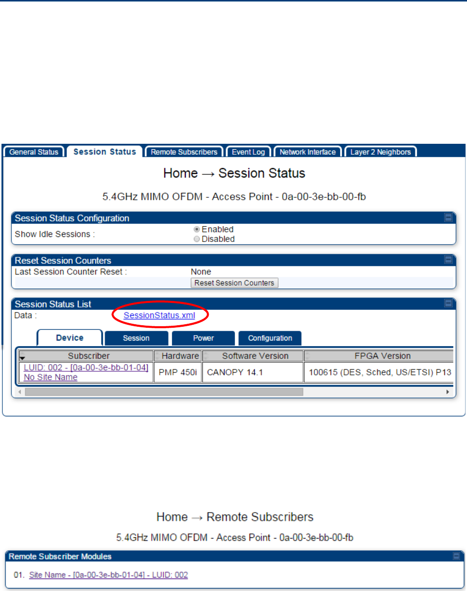
The SM/BHS may be accessed via the AP/BHM management GUI by navigating to
Home >
Session
Status
(or
Home
>
Remote Subscribers
for AP only) and clicking on the SM’s hyperlink.
For example, to access one of the SMs, click
LUID: 002 – [0a-00-3e-37-b9-fd]
, as shown in Figure
120.
Figure 120
AP Session Status page
The
SessionStatus.xml
hyper link allows user to export all displayed SM data in Session Status
table into an xml file.
To access any one of the SMs, click PMP450 platform SM
hyperlink, as shown in Figure 121.
Figure 121
AP Remote Subscribers page
Chapter 7: Configuration Monitoring the Link
Page 7-182
Monitoring the Link
Link monitoring procedure
After configuring the link, either an operator in the network office or the SM/BHS INSTALLER user
in the field (if read access to the AP/BHM is available to the INSTALLER) must perform the
following procedure. Who is authorized and able to do this depends on local operator password
policy, management VLAN setup and operational practices.
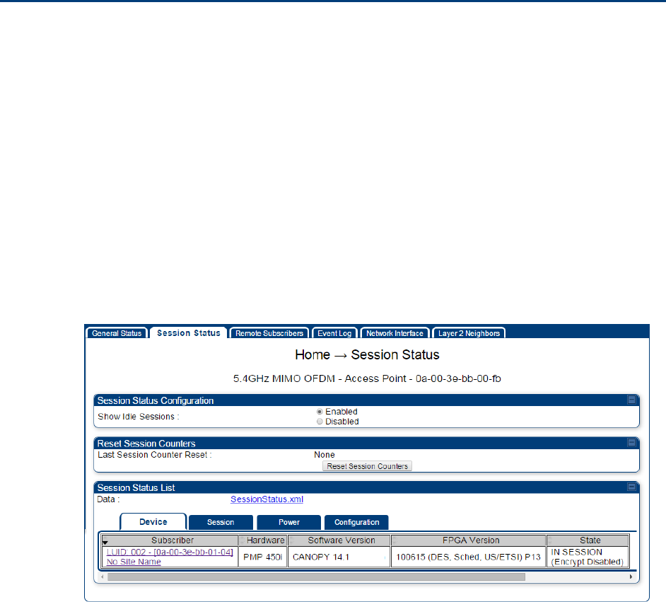
To monitor the link for performance, follow these instructions:
Procedure 21
Monitoring the AP-SM link
1
Access the web interface of the AP/BHM
2
In the left-side menu of the AP/BHM interface, select
Home
.
3
Click the
Session Status
tab.
Figure 122
Session Status page
4
The
Device
tab of Session Status List display all displayed SMs – MAC address,
PMP/PTP Hardware, Software Version, FPGA Version and State
5
Click
Session Count
tab of Session Status List to display values for
Session Count
,
Reg
Count
, and
Re-Reg Count
.
Chapter 7: Configuration Monitoring the Link
Page 7-183
•
Session Count
: This field displays how many sessions the SM/BHS has had with
the AP/BHM. Typically, this is the sum of Reg Count and Re-Reg Count. However,
the result of internal calculation may display here as a value that slightly differs
from the sum.
•
Reg Count
: When a SM/BHS makes a registration request, the AP/BHM checks its
local data to see whether it considers the SM/BHS to be already registered. If the
AP/BHM concludes that the SM/BHS is not, then the request increments the value
of this field.
• Typically, a Re-Reg is the case where both
o SM/BHS attempts to reregister for having lost communication with the
AP/BHM.
o
AP/BHM has not yet observed the link to the SM/BHS as being down.
6
Click
Power
tab of Session Status list to display Downlink Rate, AP Tx Power (dBm),
Signal Strength Radio (dB) and Signal to Noise Radio (dB).
7
Click
Configuration
tab of Session Status list to get QoS configuration details:
• Sustained Data Rate (kbps)
• Burst Allocation (kbit)
• Max Burst Rate (kbit)
• Low Priority CIR (kbps)
8
Briefly monitor these values, occasionally refreshing this page by clicking another tab
and then the Session Status tab again.
9
If these values are low (for example, 1, 1, and 0, respectively, meaning that
the SM/BHS registered and started a stable session once) and are not changing:
• Consider the installation successful.
• Monitor these values from the network office over the next several hours and days.
If these values are greater than 1, 1, and 0, or they increase while you are monitoring
them, troubleshoot the link. (For example, Use
Receive Power Level
for aiming and
then use Link Tests to confirm alignment).
Refer Viewing Session Status on page 9-15 for more details.
Chapter 7: Configuration Monitoring the Link
Page 7-184
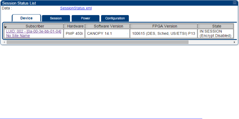
Exporting Session Status page of AP/BHM
The SessionStatus.xml hyper link allows user to export all displayed SMs or BHS data in Session
Status table into an xml file.
Figure 123
Exporting Session Status page of PMP 450i AP
In case of PMP, if the session status page does not list any SM, the SessionStatus.xml will still be
visible but the file would be empty. The file will contain data from all of the 5 different tables.
Export from command line
The scripts users can also get this file from command line, you have to authenticate successfully in
order to download the file.
Wget
http://169.254.1.1/SessionStatus.xml?CanopyUsername=test&CanopyPassword=test

Chapter 7: Configuration Configuring quality of service
Page 7-185
Configuring quality of service
Maximum Information Rate (MIR) Parameters
Point-to-multipoint links use the following MIR parameters for bandwidth management:
• Sustained Uplink Data Rate (kbps)
• Uplink Burst Allocation (kb)
• Sustained Downlink Data Rate (kbps)
• Downlink Burst Allocation (kb)
• Max Burst Downlink Data Rate (kbps)
• Max Burst Uplink Data Rate (kbps)
Set each of these parameters per AP or per SM independently.
Token Bucket Algorithm
The software uses a token bucket algorithm that has the following features:
• Stores credits (tokens) for the SM to spend on bandwidth for reception or transmission.
• Drains tokens during reception or transmission.
• Refills with tokens at the sustained rate set by the network operator.
For each token, the SM can send toward the network in the uplink (or the AP can send toward the
SM in the downlink) an equivalent number of kilobits. Two buckets determine the permitted
throughput: one in the SM for uplink and one in the AP for downlink.
The applicable set of
Uplink Burst Allocation
and
Downlink Burst Allocation
parameters determine
the number of tokens that can fill each bucket. When the SM transmits (or the AP transmits) a
packet, the equivalent number of tokens is removed from the uplink (or downlink) bucket.
Except when full, the bucket is continuously being refilled with tokens at rates that the applicable
set of
Sustained Uplink Data Rate
and
Sustained Downlink Data Rate
parameters specify. The
bucket often drains at a rate that is much faster than the sustained data rate but can refill at only
the sustained data rate. Thus, the effects of the allocation and rate parameters on packet delay are
as follows:
• The burst allocation affects how many kilobits are processed before packet delay is imposed.
• The sustained data rate affects the packet delay that is imposed.

Chapter 7: Configuration Configuring quality of service
Page 7-186
MIR Data Entry Checking
Uplink and downlink MIR is enforced as shown in Figure 124.
Note
In these figures, entry refers to the setting in the data rate parameter, not the burst
allocation parameter.
Figure 124
Uplink and downlink rate caps adjusted to apply aggregate cap
For example, in the SM, if you set the
Sustained Uplink Data Rate
parameter to 2,000 kbps and the
Sustained Downlink Data Rate
parameter to 10,000 kbps, then the uplink and downlink MIR that is
enforced for the SM can be calculated as shown in Figure 125.
Figure 125
Uplink and downlink rate cap adjustment example
`
In this example case, the derived 1,167-kbps uplink and 5,833-kbps downlink MIR sum to the fixed
7,000-kbps aggregate cap of the SM.
Committed Information Rate (CIR)
The Committed Information Rate (CIR) capability feature enables the service provider to guarantee
to any subscriber that bandwidth will never decrease to below a specified minimum unless CIR is
oversubscribed or RF conditions are degraded. CIR is oversubscribed when there is not enough
available bandwidth to support CIR configuration for all subscribers. In this condition, SMs which
are configured with a nonzero CIR will all operate at the maximum data rate supported by the link
(subject to Maximum Information Rate and Burst Rate/Allocations). SMs which are configured with
a CIR of 0 kbps will not transmit until CIR-configured SMs have completed transmission. CIR may
be configured independently for high priority traffic and for low priority traffic.
CIR parameters may be configured in the following ways:
• Web-based management GUI
• SNMP
• Authentication Server (RADIUS) - when a SM successfully registers and authenticates, CIR
information is retrieved from the RADIUS server.
uplink cap enforced =
uplink entry x aggregate cap for the SM
uplink entry + downlink entry
downlink cap enforced =
downlink entry x aggregate cap for the SM
uplink entry + downlink entry
uplink cap enforc ed =
2,000 kbps x 7,000 kbps
2,000 kbps + 10,000 kbps
= 1,167 kbps
downlink cap enforced =
10,000 kbps x 7,000 kbps
2,000 kbps + 10,000 kbps
= 5,833 kbps
Chapter 7: Configuration Configuring quality of service
Page 7-187
Active CIR configuration can be verified via the AP’s
Home >
Session Status
page.
Bandwidth from the SM Perspective
In the SM, normal web browsing, e-mail, small file transfers and short streaming video are rarely
rate limited with practical bandwidth management (QoS) settings. When the SM processes large
downloads such as software upgrades and long streaming video or a series of medium-size
downloads, the bucket rapidly drains, the burst limit is reached, and some packets are delayed.
The subscriber experience is more affected in cases where the traffic is more latency sensitive.
Interaction of Burst Allocation and Sustained Data Rate
Settings
If the Burst Allocation is set to 1200 kb and the Sustained Data Rate is set to 128 kbps, a data burst
of 1000 kb is transmitted at full speed because the Burst Allocation is set high enough. After the
burst, the bucket experiences a significant refill at the Sustained Data Rate. This configuration uses
the advantage of the settable Burst Allocation.
If both the Burst Allocation and the Sustained Data Rate are set to 128 kb, a burst is limited to the
Burst Allocation value. This configuration does not take advantage of the settable Burst Allocation.
If the Burst Allocation is set to 128 kb and the Sustained Data Rate is set to 256 kbps, the actual
rate is the burst allocation (but in kbps). As above, this configuration does not take advantage of
the settable Burst Allocation.
High-priority Bandwidth
To support low-latency traffic such as VoIP (Voice over IP) or video, the system implements a high-
priority channel. This channel does not affect the inherent latencies in the system but allows high-
priority traffic to be immediately served. The high-priority pipe separates low-latency traffic from
traffic that is latency tolerant, such as standard web traffic and file downloads.
The number of channels available on the AP is reduced by the number of SMs configured for the high-
priority channel (each SM operating with high-priority enabled uses two channels (virtual circuits) instead
of one).
A module prioritizes traffic by
• reading the Low Latency bit (Bit 3) in the IPv4 Type of Service (ToS) byte in a received packet.
Bit 3 is set by a device outside the system.
• reading the 802.1p field of the 802.1Q header in a received packet, where VLAN is enabled on
the module.
• comparing the 6-bit Differentiated Services Code Point (DSCP) field in the ToS byte of a
received packet to a corresponding value in the
Diffserv
tab of the Configuration page of the
module. A packet contains no flag that indicates whether the encoding is for the Low Latency
bit or the DSCP field. For this reason, you must ensure that all elements in your trusted
domain, including routers and endpoints, set and read the ToS byte with the same scheme.
Modules monitor ToS bytes with DSCP fields, but with the following differences:
• The 6-bit length of the field allows it to specify one of 64 service differentiations.

Chapter 7: Configuration Configuring quality of service
Page 7-188
• These correlate to 64 individual (
CodePoint
) parameters in the
Diffserv
tab of the Configuration
page.
• Per RFC 2474, 3 of these 64 are preset and cannot be changed. (See
http://www.faqs.org/rfcs/rfc1902.html.)
• For any or all of the remaining 61 CodePoint parameters, you can specify a value of
o 0 through 3 for low-priority handling.
o 4 through 7 for high-priority handling.
Note
Ensure that your Differentiated Services domain boundary nodes mark any entering
packet, as needed, so that it specifies the appropriate Code Point for that traffic and
domain. This prevents theft of service level.
An example of the
Diffserv
page in the Configuration menu and parameter descriptions are
provided under DiffServ attributes – AP/BHM on page 7-63. This tab and its rules are identical from
module type to module type. However, any of the 61 configurable Code Points can be set to a
different value from module to module, thus defining unique per-hop behavior for some traffic.
This tab in the AP sets the priorities for the various packets in the downstream (sent from the
public network). This tab in the SM sets the priorities for the various packets in the upstream (sent
to the public network).
Typically, some SMs attach to older devices that use the ToS byte as originally formatted, and
others to newer devices that use the DSCP field. The default values in the
Diffserv
page allow your
modules to prioritize traffic from the older devices roughly the same as they traditionally have.
However, these default values may result in more high-priority traffic as DSCP fields from the
newer devices are read and handled. So, after making changes in the
Diffserv
page, carefully
monitor the high-priority channel for high packet rates
• in SMs that you have identified as those to initially set and watch.
• across your network when you have broadly implemented Code Point values, such as via
SNMP.
Chapter 7: Configuration Configuring quality of service
Page 7-189
Traffic Scheduling
The characteristics of traffic scheduling in a sector are summarized in Table 140.
Table 140
Characteristics of traffic scheduling
Category
Factor
Treatment
Throughput Aggregate throughput, less additional
overhead 132 Mbps
Latency Number of frames required for the
scheduling process 1
Round-trip latency ≈ 6 ms
AP broadcast the download schedule No
High-priority
Channel
Allocation for uplink high-priority traffic
on amount of high-priority traffic
Dynamic, based on amount of high-
priority traffic
Allocation for downlink high-priority traffic
on amount of high-priority traffic
Dynamic, based on amount of high-
priority traffic
Order of transmission
CIR high-priority
CIR low-priority
Other high-priority
Other low-priority
Caution
Power requirements affect the recommended maximums for power cord length
feeding the CMM4. See the dedicated user guide that supports the CMM that you are
deploying.
Packets that have a priority of 4 to 7 in either the DSCP or a VLAN 802.1p tag are automatically sent
on the high-priority channel, but only where the high-priority channel is enabled.

Chapter 7: Configuration Configuring quality of service
Page 7-190
Setting the Configuration Source
The AP includes a
Configuration Source
parameter, which sets where SMs that register to the AP
are controlled for MIR, CIR, VLAN, and the high-priority channel as follows. The
Configuration
Source
parameter affects the source of:
• all MIR settings:
o Sustained Uplink Data Rate
o Uplink Burst Allocation
o Max Burst Uplink Data Rate
o Sustained Downlink Data Rate
o Downlink Burst Allocation
o Max Burst Downlink Data Rate
• all CIR settings:
o Low Priority Uplink CIR
o Low Priority Downlink CIR
o Hi Priority Uplink CIR
o Hi Priority Downlink CIR
• all SM VLAN settings
o Dynamic Learning
o Allow Only Tagged Frames
o VLAN Aging Timeout
o Untagged Ingress VID
o Management VID
o VLAN Membership
• the Hi Priority Channel setting
Table 141
Recommended combined settings for typical operations
Most operators who
use…
must set this
parameter…
in this web page/tab…
in the AP to…
no authentication
server
Authentication Mode
Configuration/ Security
Disabled
Configuration Source
Configuration/ General
SM
Wireless Manager
(Authentication
Server)
Authentication Mode
Configuration/ Security
Authentication Server
Configuration Source
Configuration/ General
Authentication Server
RADIUS AAA server
Authentication Mode
Configuration/ Security
RADIUS AAA
Configuration Source
Configuration/ General
Authentication Server
Chapter 7: Configuration Configuring quality of service
Page 7-191
Table 142
Where feature values are obtained for a SM with authentication required
Configuration
Source Setting
in the AP
Values are obtained from
MIR Values
VLAN Values
High Priority Channel
State
Authentication
Server
Authentication
Server
Authentication
Server
Authentication
Server
SM SM SM SM
Authentication
Server+SM
Authentication
Server
Authentication
Server, then SM
Authentication
Server, then SM
Note
HPC represents the Hi Priority Channel (enable or disable).
Where Authentication Server, then SM is the indication, parameters for which
Authentication Server does not send values are obtained from the SM. This is the case
where the Authentication Server server is operating on a Authentication Server
release that did not support the feature. This is also the case where the feature
enable/disable flag in Authentication Server is set to disabled. The values are those
previously set or, if none ever were, then the default values.
Where Authentication Server is the indication, values in the SM are disregarded.
Where SM is the indication, values that Authentication Server sends for the SM are
disregarded.
For any SM whose
Authentication Mode
parameter is not set to ‘Authentication Required’, the
listed settings are derived as shown in Table 143.
Table 143
MIR, VLAN, HPC, and CIR Configuration Sources, Authentication Disabled
Configuration
Source Setting
in the AP
Values are obtained from
MIR Values
VLAN Values
High Priority
Channel State
CIR Values
Authentication
Server
AP AP AP AP
SM SM SM SM SM
Authentication
Server+SM
SM SM SM SM
Chapter 7: Configuration Configuring quality of service
Page 7-192
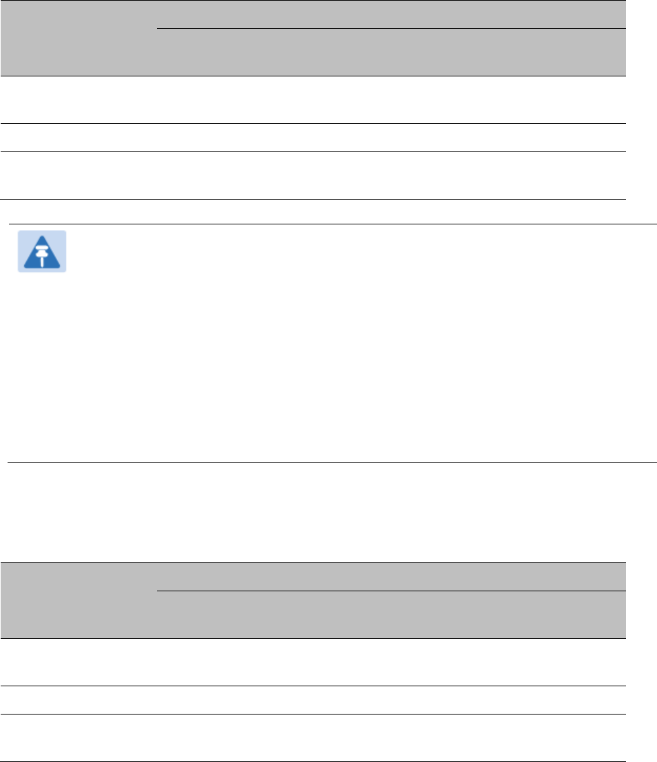
Configuring Quality of Service (QoS)
Quality of Service (QoS) page of AP
The QoS page of AP is explained in Table 144.
Table 144
QoS page attributes - AP
Attribute
Meaning
Max Burst Uplink
Data Rate
These parameters allow operators to specify the data rate at which a SM
is allowed to transmit (until burst allocation limit is reached) before
being recharged at the
Sustained Uplink Data Rate
with credits to transit
more. When set to 0 (default), the burst rate is unlimited.
Sustained Uplink
Data Rate
Specify the rate that each SM registered to this AP is replenished with
credits for transmission. This default imposes no restriction on the
uplink. See
• Maximum Information Rate (MIR) Parameters on page 7-185
• Interaction of Burst Allocation and Sustained Data Rate Settings on
page 7-187
• Configuration Source on page 7-73
Uplink Burst
Allocation
Specify the maximum amount of data to allow each SM to transmit
before being recharged at the
Sustained Uplink Data Rate
with credits to
transmit more. See Maximum Information Rate (MIR) Parameters on
page 7-185
• Interaction of Burst Allocation and Sustained Data Rate Settings on
page 7-187
• Configuration Source on page 7-73
Max Burst Downlink
Data Rate
These parameters allow operators to specify the data rate at which a SM
is allowed to transmit (until burst allocation limit is reached) before

Chapter 7: Configuration Configuring quality of service
Page 7-193
being recharged at the
Sustained Downlink Data Rate
with credits to
transit more. When set to 0 (default), the burst rate is unlimited.
Sustained Downlink
Data Rate
Specify the rate at which the AP is replenished with credits (tokens) for
transmission to each of the SMs in its sector. This default imposes no
restriction on the uplink. See Maximum Information Rate (MIR)
Parameters on page 7-185
• Interaction of Burst Allocation and Sustained Data Rate Settings on
page 7-187
• Configuration Source on page 7-73
Downlink Burst
Allocation
Specify the maximum amount of data to allow the AP to transmit to any
registered SM before the AP is replenished with transmission credits at
the
Sustained Downlink Data Rate
. See
• Maximum Information Rate (MIR) Parameters on page 7-185
• Interaction of Burst Allocation and Sustained Data Rate Settings on
page 7-187
• Configuration Source on page 7-73
Broadcast Downlink
CIR
Broadcast Downlink CIR
(Committed Information Rate, a minimum)
supports system designs where downlink broadcast is desired to have
higher priority than other traffic. For many other system designs,
especially typical internet access networks, leave the Broadcast
Downlink CIR at the default.
Broadcast Downlink CIR is closely related to the Broadcast Repeat Count
parameter, which is settable in the Radio tab of the Configuration page
in the AP: when the Broadcast Repeat Count is changed, the total of
available bandwidth is also changed, since packets are being sent one,
two, or three times, according to the setting in the Broadcast Repeat
Count parameter.
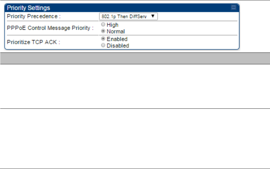
Priority Precedence Allows operator to decide if 802.1p or DiffServ priority bits must be used
first when making priority decisions.
PPPoE Control
Message Priority
Operators may configure the SM to utilize the high priority channel for
PPPoE control messages. Configuring the SM in this fashion can benefit
the continuity of PPPoE connections when there are issues with PPPoE
sessions being dropped in the network. This prioritization may be
configured in the DiffServ tab in the Configuration menu of the SM.
Prioritize TCP ACK To reduce the likelihood of TCP acknowledgement packets being
dropped, set this parameter to
Enabled
. This can improve throughput
that the end user perceives during transient periods of congestion on the
link that is carrying acknowledgements.
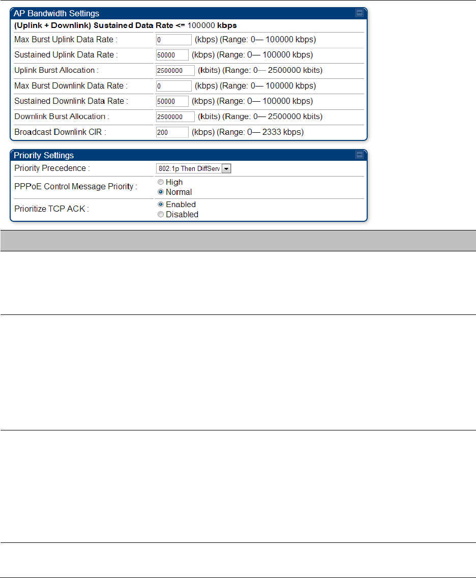
Quality of Service (QoS) page of SM
The QoS page of SM is explained in Table 145.
Chapter 7: Configuration Configuring quality of service
Page 7-194
Table 145
QoS page attributes - SM
Attribute
Meaning
Sustained Uplink
Data Rate
Specify the rate that this SM is replenished with credits for transmission.
This default imposes no restriction on the uplink. See Maximum
Information Rate (MIR) Parameters on page 7-185
• Interaction of Burst Allocation and Sustained Data Rate Settings on
page 7-187
• Configuration Source on page 7-73
Sustained Downlink
Data Rate
Specify the rate at which the AP is replenished with credits (tokens) for
transmission to this SM. This default imposes no restriction on the
uplink. See Maximum Information Rate (MIR) Parameters on Page 7-185
• Interaction of Burst Allocation and Sustained Data Rate Settings on
page 7-187
• Configuration Source on page 7-73
Uplink Burst
Allocation
Specify the maximum amount of data to allow this SM to transmit
before being recharged at the
Sustained Uplink Data Rate
with credits to
transmit more. See Maximum Information Rate (MIR) Parameters on
page 7-185
• Interaction of Burst Allocation and Sustained Data Rate Settings on
page 7-187
• Configuration Source on page 7-73
Downlink Burst
Allocation
Specify the maximum amount of data to allow the AP to transmit to this
SM before the AP is replenished at the
Sustained Downlink Data Rate

Chapter 7: Configuration Configuring quality of service
Page 7-195
with transmission credits. See Maximum Information Rate (MIR)
Parameters on page 7-185
• Interaction of Burst Allocation and Sustained Data Rate Settings on
page 7-187
• Configuration Source on page 7-73
Max Burst Uplink
Data Rate
These parameters allow operators to specify the data rate at which a SM
is allowed to transmit (until burst allocation limit is reached) before
being recharged at the
Sustained Uplink Data Rate
with credits to transit
more. When set to 0 (default), the burst rate is unlimited.
Max Burst Downlink
Data Rate
These parameters allow operators to specify the data rate at which a SM
is allowed to transmit (until burst allocation limit is reached) before
being recharged at the
Sustained Downlink Data Rate
with credits to
transit more. When set to 0 (default), the burst rate is unlimited.
Enable Broadcast /
Multicast Data Rate
This parameter allows the operator to specify if Broadcast and Multicast
data is rate-limited. This data rate can be entered in Kbps or PPS
(Packets Per Second).
Broadcast / Multicast
Data Rate
This parameter allows the operator to specify a data rate at which
Broadcast and Multicast traffic is sent via the radio link.
Low Priority Uplink
CIR
This field indicates the minimum rate at which low priority traffic is sent
over the uplink (unless CIR is oversubscribed or RF link quality is
degraded).
• Committed Information Rate (CIR) on page 7-186
• Setting the Configuration Source on page 7-190
Low Priority
Downlink CIR
This field indicates the minimum rate at which low priority traffic is sent
over the downlink (unless CIR is oversubscribed or RF link quality is
degraded).
• Committed Information Rate (CIR) on page 7-186
• Setting the Configuration Source on page 7-190
Hi Priority Channel
See
• High-priority Bandwidth on page 7-187
• Configuration Source on page 7-73
Hi Priority Uplink CIR This field indicates the minimum rate at which high priority traffic is sent
over the uplink (unless CIR is oversubscribed or RF link quality is
degraded).
• Committed Information Rate (CIR) on page 7-186
• Setting the Configuration Source on page 7-190
Hi Priority Downlink
CIR
This field indicates the minimum rate at which high priority traffic is sent
over the downlink (unless CIR is oversubscribed or RF link quality is
degraded).
• Committed Information Rate (CIR) on page 7-186
• Setting the Configuration Source on page 7-190
Chapter 7: Configuration Configuring quality of service
Page 7-196
Priority Precedence Allows operator to decide if 802.1p or DiffServ priority bits must be used
first when making priority decisions.
PPPoE Control
Message Priority
Operators may configure the SM to utilize the high priority channel for
PPPoE control messages. Configuring the SM in this fashion can benefit
the continuity of PPPoE connections when there are issues with PPPoE
sessions being dropped in the network. This prioritization may be
configured in the DiffServ tab in the Configuration menu of the SM.
Prioritize TCP ACK To reduce the likelihood of TCP acknowledgement packets being
dropped, set this parameter to Enabled. This can improve throughput
that the end user perceives during transient periods of congestion on the
link that is carrying acknowledgements. This parameter, when enabled,
can be particularly useful when running bi-direction FTP sessions over
the link. If a link is primarily used for video surveillance, it is
recommended to configure this parameter to
Disabled
.
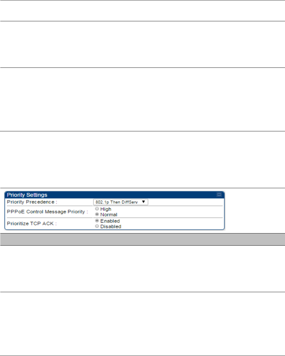
Quality of Service (QoS) page of BHM
The QoS page of BHM is explained in Table 146.
Table 146
QoS page attributes - BHM
Attribute
Meaning
PPPoE Control
Message Priority
Operators may configure the BHM to utilize the high priority channel for
PPPoE control messages. Configuring the BHM in this fashion can
benefit the continuity of PPPoE connections when there are issues with
PPPoE sessions being dropped in the network. This prioritization may be
configured in the DiffServ tab in the Configuration menu of the BHS.
Prioritize TCP ACK To reduce the likelihood of TCP acknowledgement packets being
dropped, set this parameter to Enabled. This can improve throughput
that the end user perceives during transient periods of congestion on the
link that is carrying acknowledgements. This parameter, when enabled,
can be particularly useful when running bi-direction FTP sessions over
the link. If a link is primarily used for video surveillance, it is
recommended to configure this parameter to
Disabled
.
Quality of Service (QoS) page of BHS
The QoS page of BHS is explained in Table 147.
Chapter 7: Configuration Configuring quality of service
Page 7-197
Table 147
QoS page attributes - BHS
Attribute
Meaning
PPPoE Control
Message Priority
Operators may configure the BHS to utilize the high priority channel for
PPPoE control messages. Configuring the BHS in this fashion can benefit
the continuity of PPPoE connections when there are issues with PPPoE
sessions being dropped in the network. This prioritization may be
configured in the DiffServ tab in the Configuration menu of the BHS.
Prioritize TCP ACK To reduce the likelihood of TCP acknowledgement packets being
dropped, set this parameter to Enabled. This can improve throughput
that the end user perceives during transient periods of congestion on the
link that is carrying acknowledgements. This parameter, when enabled,
can be particularly useful when running bi-direction FTP sessions over
the link. If a link is primarily used for video surveillance, it is
recommended to configure this parameter to
Disabled
.
Chapter 7: Configuration Installation Color Code
Page 7-198
Installation Color Code
With this feature enabled on the AP and SM, operators may install and remotely configure SMs
without having to configure matching color codes between the modules. While the SM is
accessible for configuration from above the AP (for remote provisioning) and below the SM (for
local site provisioning), no user data is passed over the radio link. When using the Installation
Color Code feature, ensure that the SM is configured with the factory default Color Code
configuration (Color Code 1 is “0”, Color Code 2-10 set to “0” and “Disable”). The status of the
Installation Color Code can be viewed on the AP Eval web GUI page, and when the SM is
registered using the Installation Color Code the message “SM is registered via ICC – Bridging
Disabled!” is displayed in red on every SM GUI page. The Installation Color Code parameter is
configurable without a radio reboot for both the AP and SM. If an SM is registered via Installation
Color Code and the feature is then disabled, operators will need to reboot the SM or force it to
reregister (i.e. using the
Rescan APs
functionality on the AP Eval page).
Figure 126
Installation Color Code of AP

Chapter 7: Configuration Zero Touch Configuration Using DHCP Option 66
Page 7-199
Zero Touch Configuration Using DHCP Option 66
This feature allows an SM to get its configuration via DHCP option 66. This can be used for the
initial configuration of an SM as well as managing the configuration of SMs on an ongoing basis.
Here is how it works in brief:
• When the SM boots up, if it is set to use DHCP client, it will send out a DHCP Discover packet
which includes a request for DHCP Option 66.
• In case of a brand new SM out of the box, the DHCP Discover packet is sent out if the SM
connects to an AP using Installation Color Code (ICC), even though DHCP client is not enabled
in factory default config.
• An appropriately configured DHCP server will respond with a DHCP Offer and include a URL in
response to the Option 66 request. The URL should point to the configuration file.
• The device will download the configuration file and apply it. The device will reboot
automatically if needed. (Note: this requires “rebootIfRequired” flag to be added to the config
file. See Creating a Golden config file on page 7-200.
Configuration Steps
Procedure 22
Zero Touch Configuration steps
1
Create the golden config file(s)
2
Host it on an TFTP/FTP/HTTP/HTTPS server
3
Configure the DHCP server to return the URL of the golden config file in option 66
When the SM boots up, it will get the URL for the golden config from the DHCP server via option
66, download it and apply it.
If all the SMs are configured exactly the same, then you can create just new golden config file that
can be used with all SMs.
If the SMs are not configured the same, see if it is possible to group the SMs such that SMs with
the same configuration are served by the same DHCP pool. User can then create multiple golden
config files and configure the DHCP server to use the appropriate config file for each pool.
User can also create one config file per SM. This provides the most flexibility, but is practical only
if you have a software tool/script to generate the config files for each MAC address. The files
should be named <mac>.cfg where <mac> is the MAC address of the SM, and stored in the same
directory on the file server. The DHCP server should be configured to return the directory name
ending with a ‘/’ in option 66. The SM will automatically add “<mac>.cfg” to the path and get its
config file.
Chapter 7: Configuration Zero Touch Configuration Using DHCP Option 66
Page 7-200
If some configuration is unique per SM, but rest of the configuration is common, the SMs can be
staged with the unique part, and use option 66 to manage the common part. For example, if each
SM needs to have its coordinates set, don’t include the coordinates in the golden config file.
Instead, configure the coordinates for each SM manually. Manage the rest of the configuration
using DHCP option 66.
Creating a Golden config file
The easiest way to create the golden config file is to configure an SM, export its configuration and
edit it. To export the configuration file from the GUI of the SM, go to “Configuration > Unit
Settings” tab, go to the “Download Configuration File” section and click on the “<mac>.cfg” link.
This will give you a text file in JSON format. You can edit this file in a text editor but it’s easier to
use a JSON editor like https://www.jsoneditoronline.org/.
Strip down the config file to remove sections and entries that don’t care about, and keep only the
items that require changes. If there are many required changes, it can easily get confusing. To
identify the exact items changes, first reset the SM to factory default, export the config file, make
the necessary changes, export a second config file, then use a tool like WinMerge
(http://winmerge.org/) to identify the differences.
The config file contains the following informational entries at the top level.
"cfgUtcTimestamp": "cfgUtcTimestamp",
"swVersion": "CANOPY 13.3 (Build 15) SM-AES",
"cfgFileString": "Canopy configuration file",
"srcMacAddress": "0a-00-3e-a2-c2-74",
"deviceType": "5.4/5.7GHz MIMO OFDM - Subscriber Module",
"cfgFileVersion": "1.0"
The “cfgUtcTimestamp”, “swVersion”, “srcMacAddress” and “deviceType” lines can be deleted.
Do not delete the “cfgFileString” and “cfgFileVersion” entries.
Next, create an object named “configFileParameters” at the top level. Under that, add a parameter
called “rebootIfRequired” and set it to true. This tells the SM to reboot automatically if a reboot is
needed to apply the new configuration.
A sample configuration file that has been edited for use via DHCP option 66 is given below.
{
"userParameters": {
"smNetworkConfig": {
"networkAccess": 1
},
"location": {
"siteName": "Test site"
},
"smRadioConfig": {
Chapter 7: Configuration Zero Touch Configuration Using DHCP Option 66
Page 7-201
"frequencyScanList": [
5475000,
5480000
],
"colorCodeList": [
{
"colorCode": 42,
"priority": 1
}
]
},
"networkConfig": {
"lanDhcpState": 1
}
},
"cfgFileVersion": "1.0",
"cfgFileString": "Canopy configuration file",
"configFileParameters": {
"rebootIfRequired": true
}
}
When configuration is imported, only the items that exist in the configuration file are modified.
Parameters that are not in the imported file are not changed. If user wish to revert those settings to
their factory default values, please add a “setToDefaults” item under “configFileParameters”
section with a value of true.
"cfgFileVersion": "1.0",
"cfgFileString": "Canopy configuration file",
"configFileParameters": {
"rebootIfRequired": true,
"setToDefaults": true
}
In case, the SM needs to fetch the configuration file on each boot up even when not connecting to
AP via ICC, set “Network Accessibility” to “Public” and “DHCP State” to “Enabled” in the
“Configuration > IP” page before exporting the configuration.
Hosting the config file
Copy the golden configuration file to an FTP, TFTP, HTTP or HTTPS server. This location can be
password protected; you just have to include the user name and password in the URL.
DHCP server configuration
Configure DHCP server to return the full URL to the golden config file as the value of DHCP option
66.
Chapter 7: Configuration Zero Touch Configuration Using DHCP Option 66
Page 7-202
The following example explains how to make the change for Windows Server 2008. Adapt it to
your specific DHCP server.
Procedure 23
DHCP server configuration
1
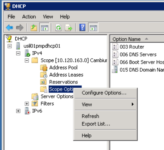
Click “Start > Administrative Tools > DHCP”
2
If you have multiple “Scopes” defined, identify the correct “Scope” that will serve IP
addresses for the SMs
3
Right click on “Scope Option” under the correct “Scope” and select “Configure
Options”
Chapter 7: Configuration Zero Touch Configuration Using DHCP Option 66
Page 7-203
4
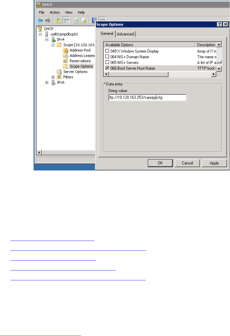
In the “Scope Options” dialog, scroll down to “066 Boot Server Host Name”, select the
checkbox and enter the full URL to the golden config file as the “String value”. Then
click “OK”.
5
In the DHCP snap-in window, right click and “Refresh” to see the DHCP option 66 in the
list of DHCP options
Supported URL Formats
FTP, TFTP, HTTP and HTTPS URLs are supported. Some examples are given below.
• ftp://10.120.163.253/canopy.cfg
• ftp://admin:admin123@10.120.163.253/canopy.cfg (login as admin with password admin123)
• tftp://10.120.163.253/canopy.cfg
• http://10.120.163.253/golden-config.cfg
• https://10.120.163.253/smconfig/golden-config.cfg
User can also specify the URL pointing to a directory and not a specific file. Terminate the URL
with a ‘/’ to indicate that it is a directory and not a file. Use this format when each SM has its own
individual config file. The directory should contain files named “<mac>.cfg”, one for each SM.
For example:
ftp://10.120.163.253/smconfig/
Chapter 7: Configuration Zero Touch Configuration Using DHCP Option 66
Page 7-204
In this case, the SM will append “<mac>.cfg” to the path and try to get that file. For example, if the
SM’s MAC address is 0a-00-3e-a2-c2-74, it will request for
ftp://10.120.163.253/smconfig/0a003ea2c274.cfg. This mechanism can be used to serve individual
config file for each SM.
Troubleshooting
1
Ensure that te SM is running 13.3 or newer version of software.
2
If the SM has factory default config, confirm ICC is enabled on the AP, so the SM can
connect to it.
3
If the SM is connecting to the AP using a color code other than ICC, make sure the SM
has “Network Accessibility” set to “Public” and “DHCP State” set to “Enabled” in the
“Configuration > IP” page.
4
Make sure the golden config file does not turn off “Network Accessibility” or “DHCP
State”. If it does, the SM will no longer request the config file when it is rebooted.
5
Check the event log of the SM to see the status of the configuration file import
including any errors that prevented it from importing the file.
6
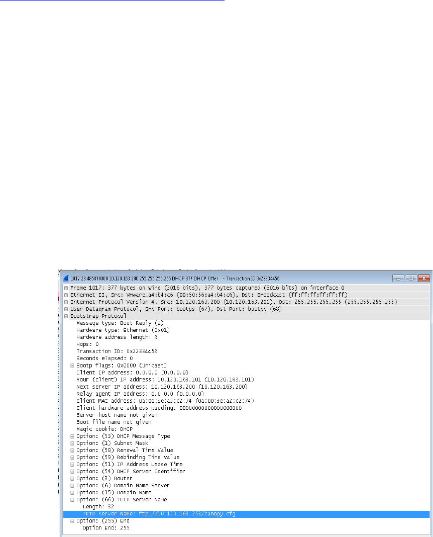
Capture the DHCP Offer packet from the DHCP server to the SM and verify that Option
66 has the expected URL.
Chapter 7: Configuration Configuring Radio via config file
Page 7-205
Configuring Radio via config file
The PMP/PTP 450 platform supports export and import of a configuration file from the AP or SM as
a text file. The configuration file is in JSON format.
To export or import the configuration file, the logged in user needs to be an ADMINISTRATOR and
it must not be a “read-only” account.
The exported configuration file contains the complete configuration including all the default
values. To keep a backup of the current configuration, the file can be saved as-is and imported
later.
While importing a configuration file, it can be either imported the full configuration or a sparse
configuration containing only the items that need to be changed. If a sparse configuration file is
imported, only the items in the file will be imported. Other configuration will remain unchanged.
There could also be used a special flag in the configuration file to tell the device to apply the
configuration starting from factory default (Refer Special Headers for configuration file on page 7-
206).
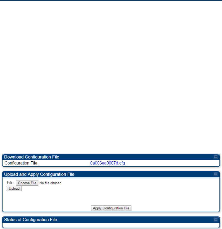
Import and Export of config file
The config file import and export is supported in
Configuration > Unit Settings
page. The
procedure for importing and exporting config file is explained below.
Figure 127
Configuration File upload and download page
The DHCP server configuration procedure is as follows:
Procedure 24
DHCP server configuration
1
Login to the GUI and go to
Configuration
>
Unit Settings.
2
Under Download Configuration File tab, click on the “<mac>.cfg” link, where <mac> is
the MAC address of the device (for example, “01003ea2c274.cfg”).
3
Save the file to the local disk.
The below procedure is to be followed for Importing a config file
Chapter 7: Configuration Configuring Radio via config file
Page 7-206
Procedure 25
Import the configuration from the GUI
1
Login to the GUI and go to Configuration → Unit Settings.
2
Click on “Browse” button under “Upload and Apply Configuration File” tab and select
the configuration file from disk.
3
Click “Upload” followed by “Apply Configuration File” button click.
4
The “Status of Configuration File” section will show the results of the upload.
5
Review it to make sure there are no errors. Then click on “Reboot” to reboot with the
imported configuration
The special headers for config file is explained below:
Procedure 26
Special Headers for configuration file
1
A "configFileParameters" section can be added to the header to control the behaviour
of the device when importing configuration.
2
The "
setToDefaults
" when set to "true" tell the device to reset to factory default
configuration and apply the configuration in the file on top of that. So any attribute not
in the configuration file will be set to its factory default value. By default, the
configuration in the file is merged with the existing configuration on the device.
The "r
ebootIfRequired
" flag when set to "true" tell the device to reboot automatically if
needed to apply the configuration change. By default, the device will not reboot
automatically.
{
"cfgFileString": "Canopy configuration file",
"cfgFileVersion": "1.0",
"configFileParameters": {
"setToDefaults":true,
"rebootIfRequired":true,
}
}

Chapter 7: Configuration Configuring a RADIUS server
Page 7-207
Configuring a RADIUS server
Configuring a RADIUS server in a PMP 450 platform network is optional, but can provide added
security, increase ease of network management and provide usage-based billing data.
Understanding RADIUS for
PMP 450 platform
PMP 450 platform modules include support for the RADIUS (Remote Authentication Dial In User
Service)
protocol supporting Authentication and Accounting.
RADIUS
Functions
RADIUS protocol support provides the
following
functions:
•
SM Authentication
allows only known SMs onto the network (blocking
“rogue”
SMs), and
can be configured to ensure SMs are connecting to a known
network
(preventing SMs from
connecting to “rogue” APs). RADIUS authentication is
used
for SMs,
but
is not used for APs.
•
SM Configuration:
Configures authenticated SMs with MIR (Maximum Information Rate), CIR
(Committed Information Rate), High Priority, and VLAN (Virtual LAN) parameters from the
RADIUS server when a SM registers to an AP.
•
SM Accounting provides
support for RADIUS accounting messages for usage-based billing.
This accounting includes indications for subscriber session establishment, subscriber session
disconnection, and bandwidth usage per session for each SM that connects to the AP.
•
Centralized AP and SM user name and password
management
allows AP
and
SM
usernames and access levels (Administrator, Installer, Technician) to
be
centrally
administered in the RADIUS server instead of on each radio and tracks
access
events
(logon/logoff) for each username on the RADIUS server. This accounting does not track and
report
specific configuration actions performed on radios or pull statistics such as
bit
counts
from the radios. Such functions require an Element Management
System
(EMS) such as
Cambium Networks Wireless Manager. This accounting is
not
the ability to perform
accounting functions on the subscriber/end
user/customer
account.
•
Framed IP
allows o
perators to use a RADIUS server to assign management IP addressing to
SM modules (framed IP address).
Tested RADIUS Servers
The Canopy RADIUS implementation has been tested and is supported
on
• FreeRADIUS, Version
2.1.8
• Aradial RADIUS, Version
5.1.12
Note
Aradial 5.3 has a bug that prevents “remote device login”, so doesn’t support the user
name and password management feature.
Chapter 7: Configuration Configuring a RADIUS server
Page 7-208
Choosing Authentication Mode and Configuring for
Authentication Servers - AP
On the AP’s
Configuration > Security
tab, select the
RADIUS AAA Authentication Mode
. The
following describes the
other
Authentication Mode
options for reference, and then the
RADIUS
AAA
option.
•
Disabled
:
Requires no authentication. Any SM (except a SM that itself has been configured
to
require
RADIUS authentication by enabling Enforce Authentication as described below) is
allowed to
register
to the
AP.
•
Authentication Server:
Authentication Server in this instance refers to Wireless Manager in
BAM-only mode. Authentication is
required
for a SM to register to the AP. Only SMs listed
by MAC address in the Wireless Manager database is
allowed to register to the
AP.
•
AP Pre-Shared
Key
:
Canopy offers a pre-shared key authentication option. In this case, an
identical key
must
be entered in the Authentication Key field on the AP’s Configuration >
Security tab and in the Authentication Key field on each desired SM’s Configuration >
Security
tab.
•
RADIUS
AAA
:
To support RADIUS authentication of SMs, on the AP’s Configuration >
Security tab
select
RADIUS AAA. Only properly configured SMs with a valid certificate is
allowed to
register
to the
AP.
When RADIUS AAA is selected, up to 3 Authentication Server (RADIUS Server)
IP
addresses
and
Shared Secrets can be configured. The IP address(s) configured here
must
match the IP
address(s) of the RADIUS server(s). The shared secret(s) configured here
must
match the shared
secret(s) configured in the RADIUS server(s). Servers 2 and 3 are meant
for
backup and
reliability, not splitting the database. If Server 1 doesn’t respond, Server 2 is
tried,
and then
server
3. If Server 1 rejects authentication, the SM is denied entry to the network, and does
not
progress trying the other
servers.
The default IP address is 0.0.0.0.
The
default Shared Secret is “CanopySharedSecret”. The
Shared Secret can be up to 32
ASCII
characters (no diacritical marks or ligatures, for
example).
Chapter 7: Configuration Configuring a RADIUS server
Page 7-209
Table 148
Security tab attributes

Chapter 7: Configuration Configuring a RADIUS server
Page 7-210
Attribute
Meaning
Authentication Mode Operators may use this field to select the following authentication
modes:
Disabled
—the AP requires no SMs to authenticate.
Authentication Server
—the AP requires any SM that attempts
registration to be authenticated in Wireless Manager before registration.
AP PreShared Key
- The AP acts as the authentication server to its SMs
and will make use of a user-configurable pre-shared authentication key.
The operator enters this key on both the AP and all SMs desired to
register to that AP. There is also an option of leaving the AP and SMs at
their default setting of using the “Default Key”. Due to the nature of the
authentication operation, if you want to set a specific authentication key,
then you MUST configure the key on all of the SMs and reboot them
BEFORE enabling the key and option on the AP. Otherwise, if you
configure the AP first, none of the SMs is able to register.
RADIUS AAA
- When RADIUS AAA is selected, up to 3 Authentication
Server (RADIUS Server) IP addresses and Shared Secrets can be
configured. The IP address(s) configured here must match the IP
address(s) of the RADIUS server(s). The shared secret(s) configured here
must match the shared secret(s) configured in the RADIUS server(s).
Servers 2 and 3 are meant for backup and reliability, not for splitting the
database. If Server 1 doesn’t respond, Server 2 is tried, and then server
3. If Server 1 rejects authentication, the SM is denied entry to the
network and does not progress trying the other servers.
Authentication
Server DNS Usage
The management DNS domain name may be toggled such that the
name of the authentication server only needs to be specified and the
DNS domain name is automatically appended to that name.
Authentication
Server 1
Enter the IP address or server name of the authentication server
(RADIUS or WM) and the Shared Secret configured in the authentication
server. When
Authentication Mode RADIUS AAA
is selected, the default
value of
Shared Secret
is “CanopySharedSecret”. The
Shared Secret
may consist of up to 32 ASCII characters.
Authentication
Server 2
Authentication
Server 3
Authentication
Server 4 (BAM Only)
Authentication
Server 5 (BAM Only)
Radius Port This field allows the operator to configure a custom port for RADIUS
server communication. The default value is 1812.
Authentication Key The authentication key is a 32-character hexadecimal string used when
Authentication Mode
is set to
AP Pre-Shared Key
. By default, this key is
set to 0xFFFFFFFFFFFFFFFFFFFFFFFFFFFFFFFF.

Chapter 7: Configuration Configuring a RADIUS server
Page 7-211
Selection Key This option allows operators to choose which authentication key is used:
Use Key above
means that the key specified in
Authentication Key
is
used for authentication
Use Default Key
means that a default key (based off of the SM’s MAC
address) is used for authentication
Encryption Key Specify the type of airlink security to apply to this AP. The encryption
setting must match the encryption setting of the SMs.
None
provides no encryption on the air link.
DES
(Data Encryption Standard): An over-the-air link encryption option
that uses secret 56-bit keys and 8 parity bits. DES performs a series of bit
permutations, substitutions, and recombination operations on blocks of
data. DES encryption does not affect the performance or throughput of
the system.
AES
(Advanced Encryption Standard)
:
An over-the-air link encryption
option that uses the Rijndael algorithm and 128-bit keys to establish a
higher level of security than DES. AES products are certified as
compliant with the Federal Information Processing Standards (FIPS 197)
in the U.S.A.
SM Display of AP
Evaluation Data
You can use this field to suppress the display of data about this AP on
the AP Evaluation tab of the Tools page in all SMs that register.
Web, Telnet, FTP
Session Timeout
Enter the expiry in seconds for remote management sessions via HTTP,
telnet, or ftp access to the AP.
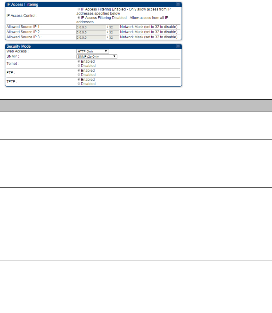
IP Access Control You can permit access to the AP from any IP address (
IP Access Filtering
Disabled
) or limit it to access from only one, two, or three IP addresses
that you specify (
IP Access Filtering Enabled
). If you select
IP Access
Filtering Enabled
, then you must populate at least one of the three
Allowed Source IP
parameters or have no access permitted from any IP
address
Allowed Source IP 1 If you selected
IP Access Filtering Enabled
for the
IP Access Control
parameter, then you must populate at least one of the three
Allowed
Source IP
parameters or have no access permitted to the AP from any IP
address. You may populate as many as all three.
Allowed Source IP 2 If you selected
IP Access Filtering Disabled
for the
IP Access Control
parameter, then no entries in this parameter are read, and access from
all IP addresses is permitted.
Allowed Source IP 3
Web Access The Radio supports secured and non-secured web access protocols.
Select suitable web access from drop down list:
•
HTTP Only
– provides non-secured web access. The radio to be
accessed via http://<IP of Radio>.
•
HTTPS Only
– provides a secured web access. The radio to be
accessed via https1://<IP of Radio>.
•
HTTP and HTTPS – If enabled, the radio can be accessed via both

Chapter 7: Configuration Configuring a RADIUS server
Page 7-212
http and https.
SNMP This option allows to configure SNMP agent communication version. It
can be selected from drop down list :
•
SNMPv2c Only
– Enables SNMP v2 community protocol.
•
SNMPv3 Only
– Enables SNMP v3 protocol. It is secured
communication protocol.
•
SNMPv2c and SNMPv3
– It enables both the protocols.
Telnet This option allows to
Enable
and
Disable
Telnet access to the Radio.
FTP This option allows to
Enable
and
Disable
FTP access to the Radio.
TFTP This option allows to
Enable
and
Disable
TFTP access to the Radio.
Chapter 7: Configuration Configuring a RADIUS server
Page 7-213
SM Authentication Mode – Require RADIUS or Follow
AP
If it is desired that a SM will only authenticate to an AP that is using RADIUS, on the
SM’s
Configuration Security tab set
Enforce Authentication
to
AAA
. With this
enabled, SM
does
not
register to an AP that has any
Authentication Mode
other than
RADIUS AAA
selected
.
If it is desired that a SM use the authentication method configured on the AP it is
registering
to,
set
Enforce Authentication
to
Disabled.
With
Enforce Authentication
disabled, a SM will
attempt to register
using
whichever
Authentication Mode
is configured on the AP it is attempting
to register
to.
Note
Having SMs to use RADIUS by enabling
Enforce Authentication
avoids the security
issue of SMs possibly registering to “rogue” APs, which have authentication
disabled.
Table 149
SM Security tab attributes
Chapter 7: Configuration Configuring a RADIUS server
Page 7-214
Attribute
Meaning
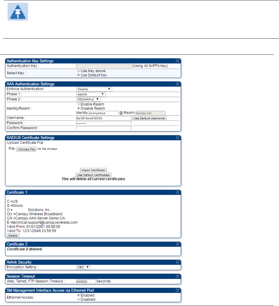
Authentication Key
The authentication key is a 32-character hexadecimal string used when
Authentication Mode
is set to
AP PreShared Key
. By default, this key is
set to 0xFFFFFFFFFFFFFFFFFFFFFFFFFFFFFFFF.
Select Key
This option allows operators to choose which authentication key is used:
Use Key above
means that the key specified in
Authentication Key
is
used for authentication
Use Default Key
means that a default key (based off of the SM’s MAC
address) is used for authentication
Enforce
Authentication
The SM may enforce authentication types of
AAA
and
AP Pre-
sharedKey
. The SM will not finish the registration process if the AP is not
using the configured authentication method (and the SM locks out the
AP for 15 minutes). Enforce Authentication default setting is
Disable.
Phase 1
The protocols supported for the
Phase 1
(Outside Identity) phase of
authentication are
EAPTTLS (Extensible Authentication Protocol
Tunneled Transport Layer
Security) or MSCHAPv2 (Microsoft
Challenge-Handshake Authentication Protocol version 2).
Phase 2
Select the desired
Phase 2
(Inside Identity) authentication protocol from
the
Phase 2
options of
PAP
(Password Authentication Protocol),
CHAP
(Challenge Handshake
Authentication
Protocol), and
MSCHAP
(
Microsoft’s version of CHAP, version 2 is used). The protocol
must
be
consistent with the authentication protocol configured on the RADIUS
server.

Chapter 7: Configuration Configuring a RADIUS server
Page 7-215
Identity/Realm
If Realms are being used, select
Enable Realm
and configure an outer
identity in the
Identity
field and a Realm in the
Realm
field. These must
match the Phase 1/Outer Identity and
Realm
configured in the RADIUS
server. The default
Identity
is “anonymous”. The
Identity
can be
up
to
128 non-special (no diacritical markings) alphanumeric characters. The
default
Realm
is
“canopy.net”. The
Realm
can also be up to 128 non-
special alphanumeric
characters.
Configure an outer Identity in the
Username
field. This must match the
Phase
1/Outer
Identity username configured in the RADIUS server. The
default Phase 1/Outer
Identity
Username
is “anonymous”. The
Username
can be up to 128 non-special (no
diacritical
markings)
alphanumeric
characters.
Username
Enter a
Username
for the SM. This must match the username
configured for the SM on
the
RADIUS server. The default
Username
is
the SM’s MAC address. The
Username
can be up
to
128 non-special
(no diacritical markings) alphanumeric
characters.
Password Enter the desired password for the SM in the
Password
and
Confirm
Password
fields
.
The
Password
must match the password configured
for the SM on the RADIUS server.
The
default
Password
is “password”.
The
Password
can be up to 128 non-special (no
diacritical
markings)
alphanumeric
characters.
Confirm Password
Upload Certificate
File
To upload a certificate manually to a SM, first load it in a known place
on your PC
or
network
drive, then click on a
Delete
button on one of
the Certificate description blocks to delete a certificate to provide space
for your certificate. Click on
Choose File,
browse to
the
location of the
certificate, and click the
Import Certificate
button, and then reboot the
radio to use the new certificate.
When a certificate is in use, after the SM successfully registers to an
AP, an indication of
In
Use
will appear in the description block of the
certificate being
used.
The public certificates installed on the SMs are used with the private
certificate on the
RADIUS
server to provide a public/private key
encryption
system.
Up to 2 certificates can be resident on a SM. An installed certificate can
be deleted
by
clicking the
Delete
button in the certificate’s description
block on the Configuration >
Security
tab. To restore the 2 default
certificates, click the
Use Default Certificates
button in
the
RADIUS
Certificate Settings
parameter block and reboot the
radio.
Encryption Setting
Specify the type of airlink security to apply to this AP. The encryption
setting must match the encryption setting of the SMs.
None
provides no encryption on the air link.
DES
(Data Encryption Standard): An over-the-air link encryption option
that uses secret 56-bit keys and 8 parity bits. DES performs a series of bit
permutations, substitutions, and recombination operations on blocks of

Chapter 7: Configuration Configuring a RADIUS server
Page 7-216
data. DES encryption does not affect the performance or throughput of
the system.
AES
(Advanced Encryption Standard)
:
An over-the-air link encryption
option that uses the Rijndael algorithm and 128-bit keys to establish a
higher level of security than DES. AES products are certified as
compliant with the Federal Information Processing Standards (FIPS 197)
in the U.S.A.
Web, Telnet, FTP
Session Timeout
Enter the expiry in seconds for remote management sessions via HTTP,
telnet or ftp access to the AP.
Ethernet Access
If you want to prevent any device that is connected to the Ethernet port
of the SM from accessing the management interface of the SM, select
Ethernet Access Disabled
. This selection disables access through this
port to via HTTP (the GUI), SNMP, telnet, FTP, and TFTP. With this
selection, management access is available through only the RF interface
via either an IP address (if
Network Accessibility
is set to
Public
on the
SM) or the Session Status or Remote Subscribers tab of the AP.. See
IP
Access Control
below.
If you want to allow management access through the Ethernet port,
select
Ethernet Access Enabled
. This is the factory default setting for this
parameter.
IP Access Control
You can permit access to the AP from any IP address (
IP Access Filtering
Disabled
) or limit it to access from only one, two, or three IP addresses
that you specify (
IP Access Filtering Enabled
). If you select
IP Access
Filtering Enabled
, then you must populate at least one of the three
Allowed Source IP
parameters or have no access permitted from any IP
address
Allowed Source IP 1 If you selected
IP Access Filtering Enabled
for the
IP Access Control
parameter, then you must populate at least one of the three
Allowed
Source IP
parameters or have no access permitted to the AP from any IP
address. You may populate as many as all three.
If you selected
IP Access Filtering Disabled
for the
IP Access Control
parameter, then no entries in this parameter are read, and access from
all IP addresses is permitted.
Allowed Source IP 2
Allowed Source IP 3
Web Access The Radio supports secured and non-secured web access protocols.
Select suitable web access from drop down list:
•
HTTP Only
– provides non-secured web access. The radio to be
accessed via http://<IP of Radio>.
•
HTTPS Only
– provides a secured web access. The radio to be
accessed via https://<IP of Radio>.
•
HTTP and HTTPS
– If enabled, the radio can be accessed via both
http and https.
SNMP This option allows to configure SNMP agent communication version. It
can be selected from drop down list :

Chapter 7: Configuration Configuring a RADIUS server
Page 7-217
•
SNMPv2c Only
– Enables SNMP v2 community protocol.
•
SNMPv3 Only
– Enables SNMP v3 protocol. It is secured
communication protocol.
•
SNMPv2c and SNMPv3
– It enables both the protocols.
Telnet This option allows to
Enable
and
Disable
Telnet access to the Radio.
FTP This option allows to
Enable
and
Disable
FTP access to the Radio.
TFTP This option allows to
Enable
and
Disable
TFTP access to the Radio.
SM - Phase 1 (Outside Identity) parameters and
settings
The protocols supported for the
Phase 1
(Outside Identity) phase of authentication
are
eapttls
(Extensible Authentication Protocol Tunneled Transport Layer
Security) and
eapMSChapV2
(Extensible Authentication Protocol – Microsoft Challenge-Handshake
Authentication Protocol).
Configure an outer Identity in the
Username
field. This must match the Phase
1/Outer
Identity
username configured in the RADIUS server. The default Phase 1/Outer
Identity
Username
is
“anonymous”. The
Username
can be up to 128 non-special (no
diacritical
markings)
alphanumeric
characters.
If Realms are being used in the RADIUS system (
eapttls
only), select
Enable Realm
and configure an outer identity in the
Identity
field and a Realm in the
Realm
field.
These must match the Phase 1/Outer Identity and
Realm
configured in the RADIUS server. The
default
Identity
is “anonymous”. The
Identity
can be
up
to
128 non-special (no diacritical markings)
alphanumeric characters. The default
Realm
is
“canopy.net”. The
Realm
can also be up to 128 non-
special alphanumeric
characters.
SM - Phase 2 (Inside Identity) parameters and
settings
If using
eapttls
for Phase 1 authentication, select the desired
Phase 2
(Inside Identity)
authentication protocol from the
Phase 2
options of
PAP
(Password Authentication Protocol),
CHAP
(Challenge Handshake
Authentication
Protocol), and
MSCHAPv2 (
Microsoft’s version of
CHAP). The protocol
must
be
consistent with the authentication protocol configured on the
RADIUS
server.
Enter a
Username
for the SM. This must match the username configured for the
SM on
the
RADIUS server. The default
Username
is the SM’s MAC address. The
Username
can
be up
to
128 non-special (no diacritical markings) alphanumeric
characters.
Enter the desired password for the SM in the
Password
and
Confirm Password
fields
.
The
Password
must match the password configured for the SM on the RADIUS server.
The
default
Password
is “password”. The
Password
can be up to 128 non-special (no
diacritical
markings)
alphanumeric
characters.

Chapter 7: Configuration Configuring a RADIUS server
Page 7-218
Handling Certificates
Managing SM Certificates via the SM GUI
The default public Canopy certificates are loaded into SMs upon factory software installation.
The default certificates are not secure and are intended for
use
during lab and field trials as part
of gaining experience with the RADIUS functionalities or as
an
option during debug. For secure
operation, an operator will want to create or procure their
own
certificates. Resetting a SM to its
factory defaults will remove the current certificates and restore the default certificates.
Up to two certificates can be resident on a SM. An installed certificate can be deleted
by
clicking
the
Delete
button in the certificate’s description block on the Configuration >
Security
tab. To
restore the 2 default certificates, click the
Use Default Certificates
button in
the
RADIUS
Certificate Settings
parameter block and reboot the
radio.
To upload a certificate manually to a SM, first load it in a known place on your PC
or
network
drive, then click on a
Delete
button on one of the Certificate description blocks to delete a
certificate to provide space for your certificate. Click on
Choose File,
browse to
the
location of the
certificate, and click the
Import Certificate
button, and then reboot the radio to use the new
certificate.
When a certificate is in use, after the SM successfully registers to an AP, an indication of
In
Use
will appear in the description block of the certificate being
used.
The public certificates installed on the SMs are used with the private certificate on the
RADIUS
server to provide a public/private key encryption
system.
Note
Root certificates of more than one level (Example - a certificate from someone who
received their CA from Verisign) fails. Certificates must be either root or self-signed.
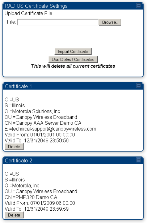
Chapter 7: Configuration Configuring a RADIUS server
Page 7-219
Figure 128
SM Certificate Management
Configuring RADIUS servers for SM authentication
Your RADIUS server must be configured to use the
following:
• EAPTTLS or MSCHAPv2 as the Phase 1/Outer Identity
protocol.
• If
Enable Realm
is selected on the SM’s
Configuration
>
Security
tab, then the
same
Realm
appears there (or access to it).
• The same Phase 2 (Inner Identity) protocol as configured on the SM’s
Configuration
>
Security
tab under Phase 2 options.
• The username and password for each SM configured on each SM’s
Configuration
> Security
tab.
• An IP address and NAS shared secret that is the same as the IP address and
Shared Secret
configured on the AP’s
Configuration > Security
tab for
that
RADIUS server.

Chapter 7: Configuration Configuring a RADIUS server
Page 7-220
• A server private certificate, server key, and CA certificate that complement
the
public
certificates distributed to the SMs, as well as the Canopy dictionary file
that
defines Vendor
Specific Attributes (VSAa). Default certificate files and
the
dictionary
file are available from
the software
site:
https://support.cambiumnetworks.com/files/pmp450 after entering your
name,
email address, and either Customer Contract Number or the MAC address of
a
module covered under the 12 month
warranty.
Optionally, operators may configure the RADIUS server response messages (Accept or Reject) so
that the user has information as to why they have been rejected. The AP displays the RADIUS
Authentication Reply message strings in the Session Status list as part of each SM’s information.
The SM will show this string (listed as Authentication Response on the SM GUI) on the main
Status page in the Subscriber Module Stats section.
Note
Aradial AAA servers only support operator-configurable Authentication Accept
responses, not Authentication Reject responses.

Chapter 7: Configuration Configuring a RADIUS server
Page 7-221
Assigning SM management IP addressing via RADIUS
Operators may use a RADIUS AAA server to assign management IP addressing to SM modules
(framed IP address). SMs now interpret attributes Framed-IP-Address, Framed-IP-Netmask, and
Cambium-Canopy-Gateway from RADIUS. The RADIUS dictionary file has been updated to include
the Cambium-Canopy-Gateway attribute and is available on the Cambium Software Support
website.
In order for these attributes to be assigned and used by the SM, the following must be true:
• The system is configured for AAA authentication
• The SM is not configured for DHCP on its management interface. If DHCP is enabled and these
attributes are configured in the RADIUS server, the attributes is ignored by the SM.
• The SM management interface must be configured to be publically accessible. If the SM is
configured to have local accessibility, the management interface will still be assigned the
framed addressing, and the SM iscome publicly accessible via the assigned framed IP
addressing.
• When using these attributes, for the addressing to be implemented by the SM operators must
configure Framed-IP-Address in RADIUS. If Framed-IP-Address is not configured but Framed-
IP-Netmask and/or Cambium-Canopy-Gateway is configured, the attributes is ignored. In the
case where only the Framed-IP-Address is configured, Framed-IP-Netmask defaults to
255.255.0.0 (NAT disabled) / 255.255.255.0 (NAT enabled) and Cambium-Canopy-Gateway
defaults to 0.0.0.0.
Configuring RADIUS server for SM configuration
Canopy Vendor Specific Attributes (VSAs) along with VSA numbers and
other
details are listed
in Table 150. The associated SM GUI page, tab and parameter are listed to aid
cross-referencing
and understanding of the
VSAs.
A RADIUS dictionary file is available from the software
site:
https://support.cambiumnetworks.com/files/pmp450
The RADIUS dictionary file
defines
the VSAs and their values and is usually imported into the
RADIUS server as part of
server
and database
setup.
Chapter 7: Configuration Configuring a RADIUS server
Page 7-222
Note
Beginning with System Release 12.0.2, two RADIUS dictionary files are available on
the Cambium website – “RADIUS Dictionary file – Cambium” and “RADIUS Dictionary
file – Motorola”.
In addition to a renaming of attributes, the Cambium-branded dictionary file contains
two new VSAs for controlling uplink and downlink Maximum Burst Data Rate (these
VSAs are listed below in Table 150).
If you are transitioning from the Motorola-branded dictionary file to the Cambium-
branded dictionary file, ensure that all RADIUS profiles containing Motorola-Canopy
attribute references are updated to include Cambium-Canopy attribute references (for
all applicable VSAs listed in Table 150). Also, ensure that all RADIUS configuration
files reference the new dictionary file (as an alternative, operators may rename the
Cambium-branded dictionary file to the filename currently in use by the RADIUS
server). Once the profiles are updated and the new Cambium-branded dictionary file is
installed on the RADIUS server, restart the RADIUS server to ensure that the new
VSAs and attribute names are enabled.
Table 150
RADIUS Vendor Specific Attributes (VSAs)
Name
Number
Type
Required
Value
MS-MPPE-Send-Key
2
26.311.16
-
Y
-
-
- -
MS-MPPE-Recv-Key
3
26.311.17
-
Y
-
-
-
-
Cambium-Canopy-LPULCIR
26.161.1
integer N
0-65535
kbps
Configuration > Quality of Service > Low Priority Uplink
CIR
0
kbps
32 bits
Cambium-Canopy-LPDLCIR
26.161.2
integer N
0-65535
kbps
Configuration > Quality of Service > Low Priority Downlink
CIR
0
kbps
32 bits
Cambium-Canopy-HPULCIR
26.161.3
integer
N
0-65535
kbps
Configuration > Quality of Service > Hi Priority Uplink
CIR
0
kbps
32 bits
Cambium-Canopy-HPDLCIR
26.161.4
integer
N
0-65535
kbps
Configuration > Quality of Service > Hi Priority Uplink
CIR
0
kbps
32 bits
Cambium-Canopy-HPENABLE
26.161.5
integer
N
0-disable,
1-enable
2 Contains key for encrypting packets sent by the NAS to the remote host (for Microsoft Point-to-Point
Encryption Protocol)
3 Contains key for encrypting packets received by the NAS from the remote host (for Microsoft Point-
to-Point Encryption Protocol)

Chapter 7: Configuration Configuring a RADIUS server
Page 7-223
Configuration > Quality of Service > Hi Priority
Channel
Enable/Disable
0
32 bits
26.161.6
integer
N
0-100000
kbps
Configuration > Quality of Service > Sustained Uplink
Data
Rate
dependent
on
radio
feature
set
32 bits
Cambium-Canopy-ULBL
26.161.7
integer
N
0-2500000
kbps
Configuration > Quality of Service > Uplink Burst
Allocation
dependent
on
radio
feature
set
32 bits
Cambium-Canopy-DLBR
26.161.8
integer N
0-100000
kbps
Configuration > Quality of Service > Sustained Downlink
Data
Rate
dependent
on
radio
feature
set
32 bits
Cambium-Canopy-DLBL
26.161.9
integer
N
0-2500000
kbps
Configuration > Quality of Service > Downlink Burst
Allocation
dependent
on
radio
feature
set
32 bits
Cambium-Canopy-
VLLEARNEN
26.161.14
integer
N
0-disable,
1-enable
Configuration > VLAN > Dynamic
Learning 1
32 bits
Cambium-Canopy-
VLFRAMES
26.161.15 integer
N
0-all, 1-tagged,
2-
untagged
Configuration > VLAN > Allow Frame
Types 0
32 bits
Cambium-Canopy-VLIDSET
26.161.16 integer N
VLAN Membership
(1-4094)
Configuration > VLAN
Membership 0
32 bits
Cambium-Canopy-VLAGETO
26.161.20 integer
N
5 - 1440
minutes
Configuration > VLAN > VLAN Aging
Timeout
25
mins
32 bits
Cambium-Canopy-VLIGVID
26.161.21
integer
N
1 –
4094
Configuration > VLAN > Default Port
VID 1
32 bits
Cambium-Canopy-VLMGVID
26.161.22 integer
N
1 –
4094
Configuration > VLAN > Management
VID 1
32 bits
Cambium-Canopy-
VLSMMGPASS
26.161.23 integer
N
0-disable,
1-enable
Configuration > VLAN > SM Management VID
Pass-through 1
32 bits
Cambium-Canopy-BCASTMIR
26.161.24 integer
N
0-100000 kbps,
0=disabled
Configuration > Quality of Service > Broadcast/Multicast
Uplink
Data Rate
dependent
on
radio
feature
set
32 bits
Chapter 7: Configuration Configuring a RADIUS server
Page 7-224
Cambium-Canopy-Gateway
26.161.25 ipaddr N
-
Configuration > IP > Gateway IP Address
0.0.0.0 -
Cambium-Canopy-ULMB 26.161.26
integer
N
0-100000 kbps
Configuration > Quality of Service > Max Burst Uplink Data
Rate
0 32 bits
Cambium-Canopy-DLMB 26.161.27
integer
N
0-100000 kbps
Configuration > Quality of Service > Max Burst Downlink Data
Rate
0 32 bits
Cambium-Canopy-UserLevel 26.161.50
integer
N
1-Technician,
2-
Installer, 3-
Administrator
Account > Add User >
Level 0
32 bits
Note
VSA
numbering:
26 connotes Vendor Specific Attribute, per RFC
2865
26.311 is Microsoft Vendor Code, per
IANA
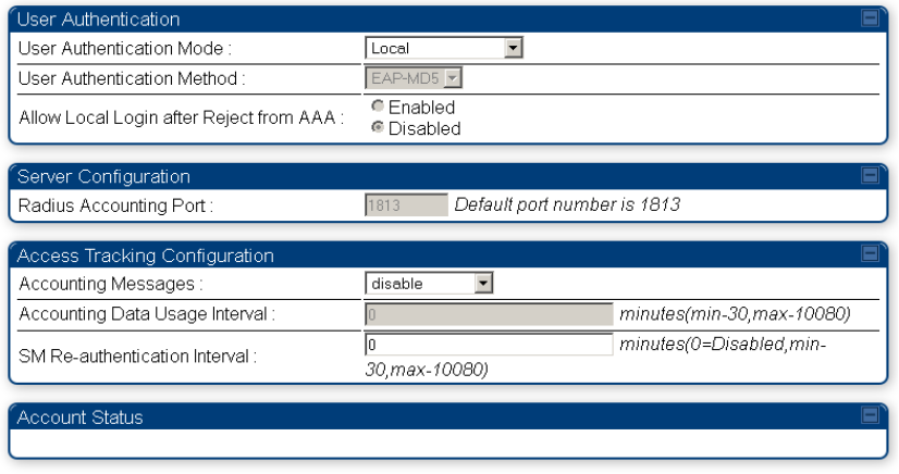
Chapter 7: Configuration Configuring a RADIUS server
Page 7-225
Using RADIUS for centralized AP and SM user name and
password management
AP – Technician/Installer/Administrator
Authentication
To control technician, installer, and administrator access to the AP from a centralized
RADIUS
server:
Procedure 27
Centralized user name and password management for AP
1
Set
Authentication Mode
on the AP’s Configuration > Security tab to
RADIUS AAA
2
Set
User Authentication Mode
on the AP’s Account > User Authentication
tab
(the tab
only appears after the AP is set to RADIUS authentication) to
Remote
or
Remote then
Local
.
•
Local
: The local SM is checked for accounts. No centralized
RADIUS
accounting
(access control)
is
performed.
•
Remote
: Authentication by the centralized RADIUS server
is
required to gain access
to the SM if the SM is registered to an
AP
that has
RADIUS AAA Authentication
Mode
selected. For up to
2
minutes a test pattern is displayed until the server
responds
or
times
out.
•
Remote then Local
: Authentication using the centralized
RADIUS
server is
attempted. If the server sends a reject message, then
the
setting of
Allow Local
Login after Reject from AAA
determines
if
the local user database is checked or
not. If the configured
servers
do
not respond within 2 minutes, then the local user
database
is
used. The successful login method is displayed in the
navigation
column of the SM.
Figure 129
User Authentication and Access Tracking tab of the AP
Chapter 7: Configuration Configuring a RADIUS server
Page 7-226
Table 151
AP User Authentication and Access Tracking attributes
Attribute
Meaning
User Authentication
Mode
•
Local
: The local SM is checked for accounts. No centralized
RADIUS
accounting (access control)
is
performed.
•
Remote
: Authentication by the centralized RADIUS server
is
required to gain access to the AP. For up to
2
minutes a test pattern
is displayed until the server responds
or
times
out.
•
Remote then Local
: Authentication using the centralized
RADIUS
server is attempted. If the server sends a reject message, then
the
setting of
Allow Local Login after Reject from AAA
determines
if
the local user database is checked or not. If the configured
servers
do
not respond within 2 minutes, then the local user database
is
used. The successful login method is displayed in the
navigation
column of the AP.
User Authentication
Method
The user authentication method employed by the radios is EAP-MD5.
Allow Local Login after
Reject from AAA
If a user authentication is rejected from the AAA server, the user is
allowed to login locally to the radio’s management interface.
Radius Accounting
Port
The destination port on the AAA server used for Radius accounting
communication.
Accounting Messages
disable – no accounting messages are sent to the RADIUS server
deviceAccess – accounting messages are sent to the RADIUS server
regarding device access (see Table 153).
dataUsage – accounting messages are sent to the RADIUS server
regarding data usage (see Table 153).
Accounting Data
Usage Interval
The interval for which accounting data messages are sent from the radio
to the RADIUS server. If 0 is configured for this parameter, no data
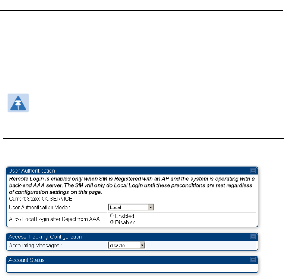
Chapter 7: Configuration Configuring a RADIUS server
Page 7-227
usage messages are sent.
SM Re-authentication
Interval
The interval for which the SM will re-authenticate to the RADIUS server.
SM – Technician/Installer/Administrator
Authentication
The centralized user name and password management for SM is same as AP. Follow AP –
Technician/Installer/Administrator Authentication on page 7-225 procedure.
Note
Remote access control is enabled only after the SM registers to an AP that has
Authentication Mode
set to
RADIUS AAA
. Local access control will always be used
before registration and is used after registration if the AP is not configured for
RADIUS.
Figure 130
User Authentication and Access Tracking tab of the SM
Chapter 7: Configuration Configuring a RADIUS server
Page 7-228
Table 152
SM User Authentication and Access Tracking attributes
Attribute Meaning
User Authentication
Mode
•
Local
: The local SM is checked for accounts. No centralized RADIUS
accounting (access control) is performed.
•
Remote
: Authentication by the centralized RADIUS server is required
to gain access to the SM if the SM is registered to an AP that has
RADIUS AAA Authentication Mode
selected. For up to 2 minutes a
test pattern is displayed until the server responds or times out.
•
Remote then Local
: Authentication using the centralized RADIUS
server is attempted. If the server sends a reject message, then the
setting of
Allow Local Login after Reject from AAA
determines if the
local user database is checked or not. If the configured servers do
not respond within 2 minutes, then the local user database is used.
The successful login method is displayed in the navigation column
of the SM.
Allow Local Login
after Reject from
AAA
If a user authentication is rejected from the AAA server, the user is
allowed to login locally to the radio’s management interface. It is
applicable ONLY when the
User Authentication Mode
is set to “
Remote
then Loca
l”.
Note
When the radio User Authentication Mode is set to
“Local” or “Remote”, the Allow Local Login after Reject
from AAA does not any effect.
Accounting
Messages
• disable – no accounting messages are sent to the RADIUS server
• deviceAccess – accounting messages are sent to the RADIUS server
regarding device access (see Table 153).

Chapter 7: Configuration Configuring a RADIUS server
Page 7-229
Access
Tracking
To track logon and logoff times on individual radios by technicians, installers, and
administrators, on the AP or SM’s
Account
>
User Authentication and Access Tracking
tab
under
Accounting
(Access Tracking) set
Accounting Messages
to “deviceAccess”.
Device Access Tracking
is enabled separately from
User Authentication Mode
. A given AP
or
SM
can be configured for both, either, or
neither.
RADIUS Device Data Accounting
PMP 450 systems include support for RADIUS accounting messages for usage-based billing. This
accounting includes indications for subscriber session establishment, subscriber session
disconnection, and bandwidth usage per session for each SM that connects to the AP. The
attributes included in the RADIUS accounting messages are shown in the table below.
Table 153
Device data accounting RADIUS attributes
Sender Message Attribute Value Description
AP Accounting-
Request
Acct-Status-Type 1 - Start This message is
sent every time a
SM registers with
an AP, and after
the SM stats are
cleared.
Acct-Session-Id
Unique per AP session.
Initial value is SM MAC, and
increments after every start
message sent of an in
session SM.
Event-Timestamp UTC time the event
occurred on the AP
AP Accounting-
Request
Acct-Status-Type 2 - Stop This message is
sent every time a
SM becomes
unregistered with
an AP, and when
the SM stats are
cleared.
Acct-Session-Id
Unique per AP session.
Initial value is SM MAC, and
increments after every start
message sent of an in
session SM.
Acct-Input-Octets
Sum of the input octets
received at the SM over
regular data VC and the
high priority data VC (if
enabled). Will not include
broadcast.
Acct-Output-Octets
Sum of the output octets
sent from the SM over
regular data VC and the
high priority data VC (if
enabled).

Chapter 7: Configuration Configuring a RADIUS server
Page 7-230
Sender Message Attribute Value Description
Acct-Input-
Gigawords
Number of times the Acct-
Input-Octets counter has
wrapped around 2^32 over
the course of the session
Acct-Output-
Gigawords
Number of times the Acct-
Output-Octets counter has
wrapped around 2^32 over
the course of the session
Acct-Input-Packets
Sum of unicast and
multicast packets that are
sent to a particular SM over
the regular data VC and the
high priority data VC (if
enabled). It will not include
broadcast.
Acct-Output-
Packets
Sum of unicast and
multicast packets that are
sent from a particular SM
over the regular data VC
and the high priority data
VC (if enabled).
Acct-Session-Time Uptime of the SM session.
Acct-Terminate-
Cause
Reason code for session
termination
AP Accounting-
Request
Acct-Status-Type 3 - Interim-Update This message is
sent periodically
per the operator
configuration on
the AP in seconds.
Interim update
counts are
cumulative over
the course of the
session
Acct-Session-Id
Unique per AP session.
Initial value is SM MAC, and
increments after every start
message sent of an in
session SM.
Acct-Input-Octets
Sum of the input octets sent
to the SM over regular data
VC and the high priority
data VC (if enabled). Will
not include broadcast.
Acct-Output-Octets
Sum of the output octets
set from the SM over
regular data VC and the
high priority data VC (if
enabled).
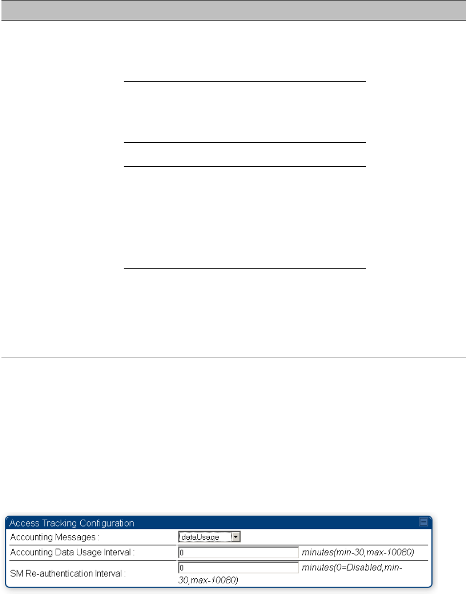
Chapter 7: Configuration Configuring a RADIUS server
Page 7-231
Sender Message Attribute Value Description
Acct-Input-
Gigawords
Number of times the Acct-
Input-Octets counter has
wrapped around 2^32 over
the course of the session
Acct-Output-
Gigawords
Number of times the Acct-
Output-Octets counter has
wrapped around 2^32 over
the course of the session
Acct-Session-Time Uptime of the SM session.
Acct-Input-Packets
Sum of unicast and
multicast packets that are
sent to a particular SM over
the regular data VC and the
high priority data VC (if
enabled). It will not include
broadcast.
Acct-Output-
Packets
Sum of unicast and
multicast packets that are
sent from a particular SM
over the regular data VC
and the high priority data
VC (if enabled).
The data accounting configuration is located on the AP’s
Accounts
>
User Authentication and
Access Tracking
GUI menu, and the AP’s
Authentication Mode
must be set to
Radius AAA
for the
menu to appear. The accounting may be configured via the AP GUI as shown in the figures below.
By default accounting messages are not sent and the operator has the choice of configuring to
send only Device Access accounting messages (when a user logs in or out of the radio), only Data
Usage messages, or both. When Data Accounting is enabled, the operator must specify the
interval of when the data accounting messages are sent (0 – disabled, or in the range of 30-10080
minutes). The default interval is 30 minutes.
Figure 131
RADIUS accounting messages configuration
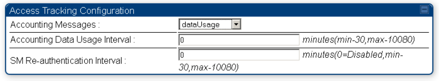
Chapter 7: Configuration Configuring a RADIUS server
Page 7-232
The data accounting message data is based on the SM statistics that the AP maintains, and these
statistics may be cleared on the AP by an operator. If an operator clears these messages and data
accounting is enabled, an accounting stop message is sent followed by an accounting start
message to notify the AAA of the change.
If an operator clears the VC statistics on the device through the management GUI, a RADIUS stop
message and data start message is issued for each device affected. The start and stop messages
will only be sent once every 5 minutes, so if an operator clears these statistics multiple times
within 5 minutes, only one set of data stop/start messages is sent. This may result in inaccurate
data accumulation results.
RADIUS Device Re-authentication
PMP 450 platform systems include support for periodic SM re-authentication in a network without
requiring the SM to re-register (and drop the session). The re-authentication may be configured to
occur in the range of every 30 minutes to weekly.
Figure 132
Device re-authentication configuration
The re-authentication interval is only configurable on the AP. When this feature is enabled, each
SM that enters the network will re-authenticate each the interval time has expired without
dropping the session. The response that the SM receives from the AAA server upon re-
authentication is one of the following:
•
Success
: The SM continues normal operation
•
Reject
: The SM de-registers and will attempt network entry again after 1 minute and then if
rejected will attempt re-entry every 15 minutes
•
Timeout or other error
: The SM remains in session and attempt 5 times to re-authenticate with
the RADIUS-REQUEST message. If these attempts fail, then the SM will go out of session and
proceed to re-authenticate after 5 minutes, then every 15 minutes.
Although re-authentication is an independent feature, it was designed to work alongside with the
RADIUS data usage accounting messages. If a user is over their data usage limit the network
operator can reject the user from staying in the network. Operators may configure the RADIUS
‘Reply-Message’ attribute with an applicable message (i.e. “Data Usage Limit Reached”) that is
sent to the subscriber module and displayed on the general page.

Page 8-1
Chapter 8: Tools
The AP and SM GUIs provide several tools to analyze the operating environment, system
performance and networking, including:
• Using Spectrum Analyzer tool on page 8-2
• Using the Alignment Tool on page 8-15
• Using the Link Capacity Test tool on page 8-21
• Using AP Evaluation tool on page 8-24
• Using BHM Evaluation tool on page 8-28
• Using the OFDM Frame Calculator tool on page 8-32
• Using the Subscriber Configuration tool on page 8-36
• Using the Link Status tool on page 8-37
• Using BER Results tool on page 8-40
• Using the Sessions tool on page 8-41
Chapter 8: Tools Using Spectrum Analyzer tool
Page 8-2
Using Spectrum Analyzer tool
The integrated spectrum analyzer can be very useful as a tool for troubleshooting and RF planning,
but is not intended to replicate the accuracy and programmability of a high-end spectrum analyzer,
which sometime can be used for other purposes.
The AP/BHM and SM/BHS perform spectrum analysis together in the Sector Spectrum Analyzer
tool.
Caution
On start of the Spectrum Analyzer on a module, it enters a scan mode and drops any
RF connection it may have had. When choosing
Start Timed Spectrum Analysis
, the
scan is run for the amount of time specified in the
Duration
configuration parameter.
When choosing
Start Continuous Spectrum Analysis
, the scan is run continuously for
24 hours, or until stopped manually (using the
Stop Spectrum Analysis
button).
Any module can be used to see the frequency and power level of any detectable signal that is
within, just above, or just below the frequency band range of the module.
Note
Vary the days and times when you analyze the spectrum in an area. The RF
environment can change throughout the day or throughout the week.
Mapping RF Neighbor Frequencies
The neighbor frequencies can be analyzed using Spectrum Analyzer tool. Following modules allow
user to:
• Use a BHS or BHM for PTP and SM or AP for PMP as a Spectrum Analyzer.
• View a graphical display that shows power level in RSSI and dBm at 5 MHz increments
throughout the frequency band range, regardless of limited selections in the
Custom Radio
Frequency Scan Selection List
parameter of the SM/BHS.
• Select an AP/BHM channel that minimizes interference from other RF equipment.
Caution
The following procedure causes the SM/BHS to drop any active RF link. If a link is
dropped when the spectrum analysis begins, the link can be re-established when
either a 15 minute interval has elapsed or the spectrum analyzer feature is disabled.
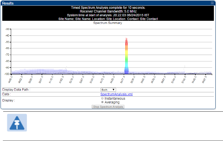
Chapter 8: Tools Using Spectrum Analyzer tool
Page 8-3
Temporarily deploy a SM/BHS for each frequency band range that need to monitor and access the
Spectrum Analyzer tab in the Tools web page of the module.
• Using Spectrum Analyzer tool
• Using the Remote Spectrum Analyzer tool
Spectrum Analyzer tool
Analyzing the spectrum
To use the built-in spectrum analyzer functionality of the AP/SM/BH, proceed as follows:
Procedure 28
Analyzing the spectrum
1
Predetermine a power source and interface that works for the AP/SM/BH in the
area to be analyzed.
2
Take the AP/SM/BH, power source and interface device to the area.
3
Access the
Tools
web page of the AP/SM/BH.
4
Enter
Duration
in Timed Spectrum Analyzer Tab. Default value is 10 Seconds
5
Click
Start Timed Sector Spectrum Analysis
6
The results are displayed:
Figure 133
Spectrum analysis - Results
Note
AP/SM/BH scans for extra 40 seconds in addition to configured
Duration
7
Travel to another location in the area to BHS.
8
Click
Start Timed Spectrum Analysis

Chapter 8: Tools Using Spectrum Analyzer tool
Page 8-4
9
Repeat Steps 4 and 6 until the area has been adequately scanned and logged.
As with any other data that pertains to your business, a decision today to put the data into a
retrievable database may grow in value to you over time.
Note
Wherever the operator find the measured noise level is greater than the sensitivity of
the radio that is plan to deploy, use the noise level (rather than the link budget) for
your link feasibility calculations.
The AP/SM/BH perform spectrum analysis together in the Sector Spectrum Analyzer
feature.
Graphical spectrum analyzer display
The AP/SM/BH display the graphical spectrum analyzer. An example of the
Spectrum Analyzer
page is shown in Figure 133.
The navigation feature includes:
• Results may be panned left and right through the scanned spectrum by clicking and dragging
the graph left and right
• Results may be zoomed in and out using mouse
When the mouse is positioned over a bar, the receive power level, frequency, maximum and mean
receive power levels are displayed above the graph
To keep the displayed data current, either set “Auto Refresh” on the module’s
Configuration >
General.
Spectrum Analyzer page of AP
The Spectrum Analyzer page of AP is explained in Table 154.
Chapter 8: Tools Using Spectrum Analyzer tool
Page 8-5
Table 154
Spectrum Analyzer page attributes - AP
Attribute
Meaning
Display Data Path
Both
means that the vertical and horizontal paths are displayed or an
individual path may be selected to display only a single-path reading.
Data For ease of parsing data and to facilitate automation, the spectrum
analyzer results may be saved as an XML file. To save the results in an
XML formatted file, right-click the “SpectrumAnalysis.xml” link and save
the file.
Display
Instantaneous
means that each reading (vertical bar) is displayed with
two horizontal lines above it representing the max power level received
(top horizontal line) and the average power level received (lower
horizontal line) at that frequency.
Averaging
means that each reading (vertical bar) is displayed with an
associated horizontal line above it representing the max power level
received at that frequency.
Registered SM Count This field displays the MAC address and Site Name of the registered SM.
Maximum Count of
Registered SMs
This field displays the maximum number of registered SMs.
Duration This field allows operators to configure a specified time for which the
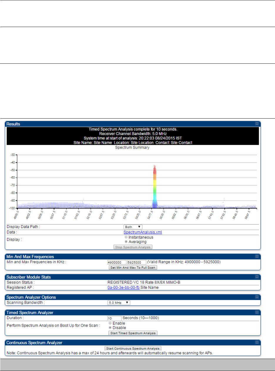
Chapter 8: Tools Using Spectrum Analyzer tool
Page 8-6
spectrum is scanned. If the entire spectrum is scanned prior to the end of
the configured duration, the analyzer will restart at the beginning of the
spectrum.
Continuous
Spectrum Analyzer
Start Continuous Spectrum Analysis
button ensures that when the SM is
powered on, it automatically scans the spectrum for 10 seconds. These
results may then be accessed via the
Tools > Spectrum Analyzer
GUI
page.
Spectrum Analyzer page of SM
The Spectrum Analyzer page of SM is explained in Table 155.
Table 155
Spectrum Analyzer page attributes - SM
Attribute
Meaning

Chapter 8: Tools Using Spectrum Analyzer tool
Page 8-7
Display Data Path Refer Table 154 on page 8-5
Data Refer Table 154 on page 8-5
Display Refer Table 154 on page 8-5
Min and Max
Frequencies in KHz
To scan min to max range of frequencies, enter min and max
frequencies in KHz and press
Set Min and Max to Full Scan
button.
To scan +/- 40 MHz from center frequency, enter center frequency in KHz
and press
Set Min And Max To Center Scan +/- 40KHz
button.
Registered SM Count Refer Table 154 on page 8-5
Maximum Count to
Registered SMs
Refer Table 154 on page 8-5
Duration Refer Table 154 on page 8-5
Spectrum Analyzer page of BHM
The Spectrum Analyzer page of BHM is explained in Table 156.
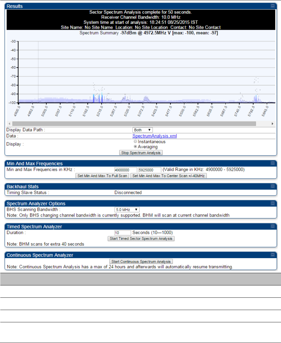
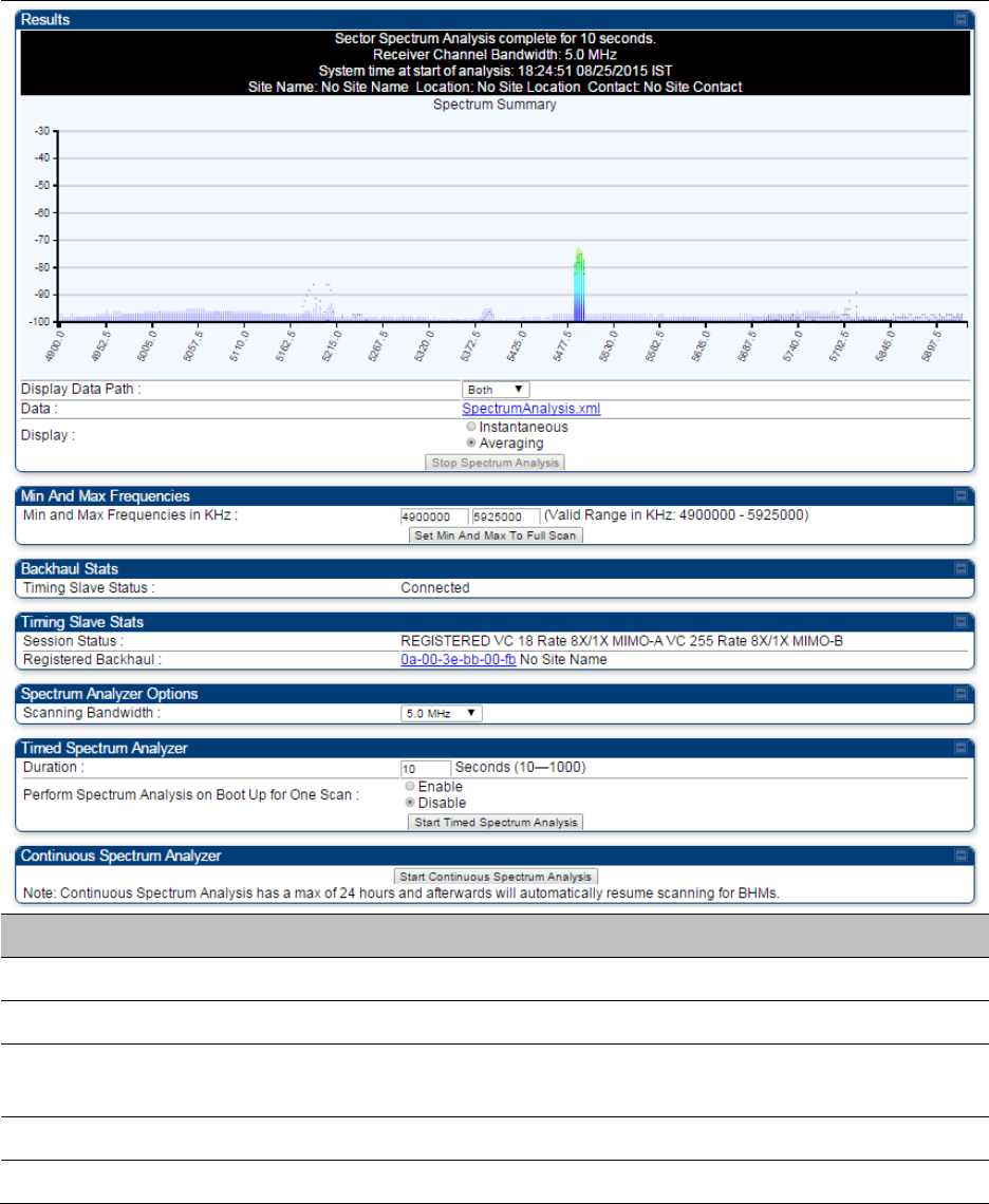
Chapter 8: Tools Using Spectrum Analyzer tool
Page 8-9
Spectrum Analyzer page of BHS
The Spectrum Analyzer page of BHS is explained in Table 157.
Table 157
Spectrum Analyzer page attributes - BHS
Attribute
Meaning
Data Refer Table 154 on page 8-5
Display Refer Table 154 on page 8-5
Session Status This field displays current session status and rates. The session states
can be Scanning, Syncing, Registering or Registered.
Registered Backhaul This field displays MAC address of BHM and PTP model number
Duration Refer Table 154 on page 8-5

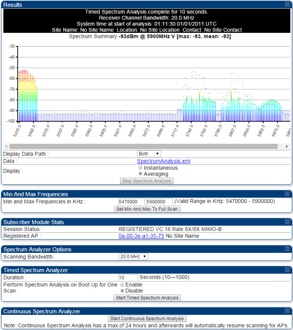
Chapter 8: Tools Using Spectrum Analyzer tool
Page 8-11
Spectrum Analyzer page result of PMP 450 SM
Figure 134
Spectrum Analyzer page result – PMP 450 SM
Chapter 8: Tools Using Spectrum Analyzer tool
Page 8-12
Remote Spectrum Analyzer tool
The Remote Spectrum Analyzer tool in the AP/BHM provides additional flexibility in the use of the
spectrum analyzer in the SM/BHS. Set the duration of 10 to 1000 seconds, then click the
Start
Remote Spectrum Analysis
button to launch the analysis from that SM/BHS.
In PMP configuration, a SM has to be selected from the drop-down list before launching
Start
Remote Spectrum Analysis
.
Analyzing the spectrum remotely
Procedure 29
Remote Spectrum Analyzer procedure
1
The AP/BHM de-registers the target SM/BHS.
2
The SM/BHS scans (for the duration set in the AP/BHM tool) to collect data for the
bar graph.
3
The SM/BHS re-registers to the AP/BHM.
4
The AP/BHM displays the bar graph.
The bar graph is an HTML file, but can be changed to an XML file, which is then easy to analyze
through the use of scripts that you may write for parsing the data. To transform the file to XML,
click the “SpectrumAnalysis.xml” link below the spectrum results. Although the resulting display
appears mostly unchanged, the bar graph is now coded in XML. You can now right-click on the bar
graph for a
Save Target As
option to save the Spectrum Analysis.xml file.
Remote Spectrum Analyzer page of AP
The Remote Spectrum Analyzer page of AP is explained in Table 158.
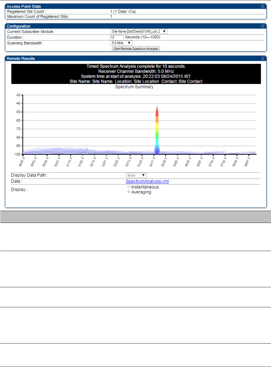
Chapter 8: Tools Using Spectrum Analyzer tool
Page 8-13
Table 158
Remote Spectrum Analyzer attributes - AP
Attribute
Meaning
Registered SM Count This field displays the number of SMs that were registered to the AP
before the SA was started. This helps the user know all the SMs re-
registered after performing a SA.
Maximum Count of
Registered SMs
This field displays the largest number of SMs that have been
simultaneously registered in the AP since it was last rebooted. This
count can provide some insight into sector history and provide
comparison between current and maximum SM counts at a glance.
Current Subscriber
Module
The SM with which the Link Capacity Test is run.
Duration This field allows operators to configure a specified time for which the
spectrum is scanned. If the entire spectrum is scanned prior to the end of
the configured duration, the analyzer will restart at the beginning of the
spectrum.
Scanning Bandwidth This parameter defines the size of the channel scanned when running
the analyzer.
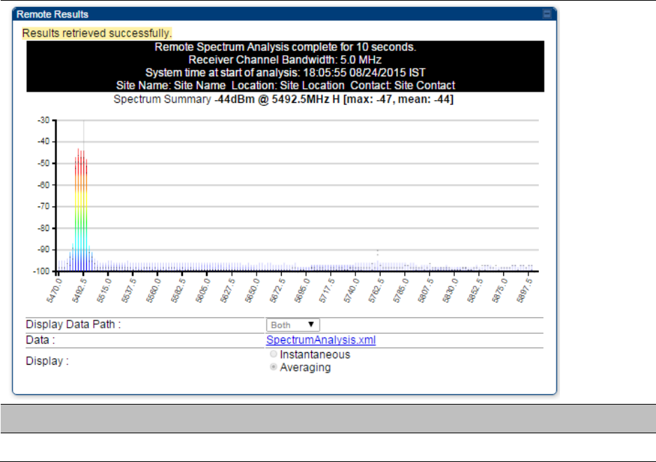
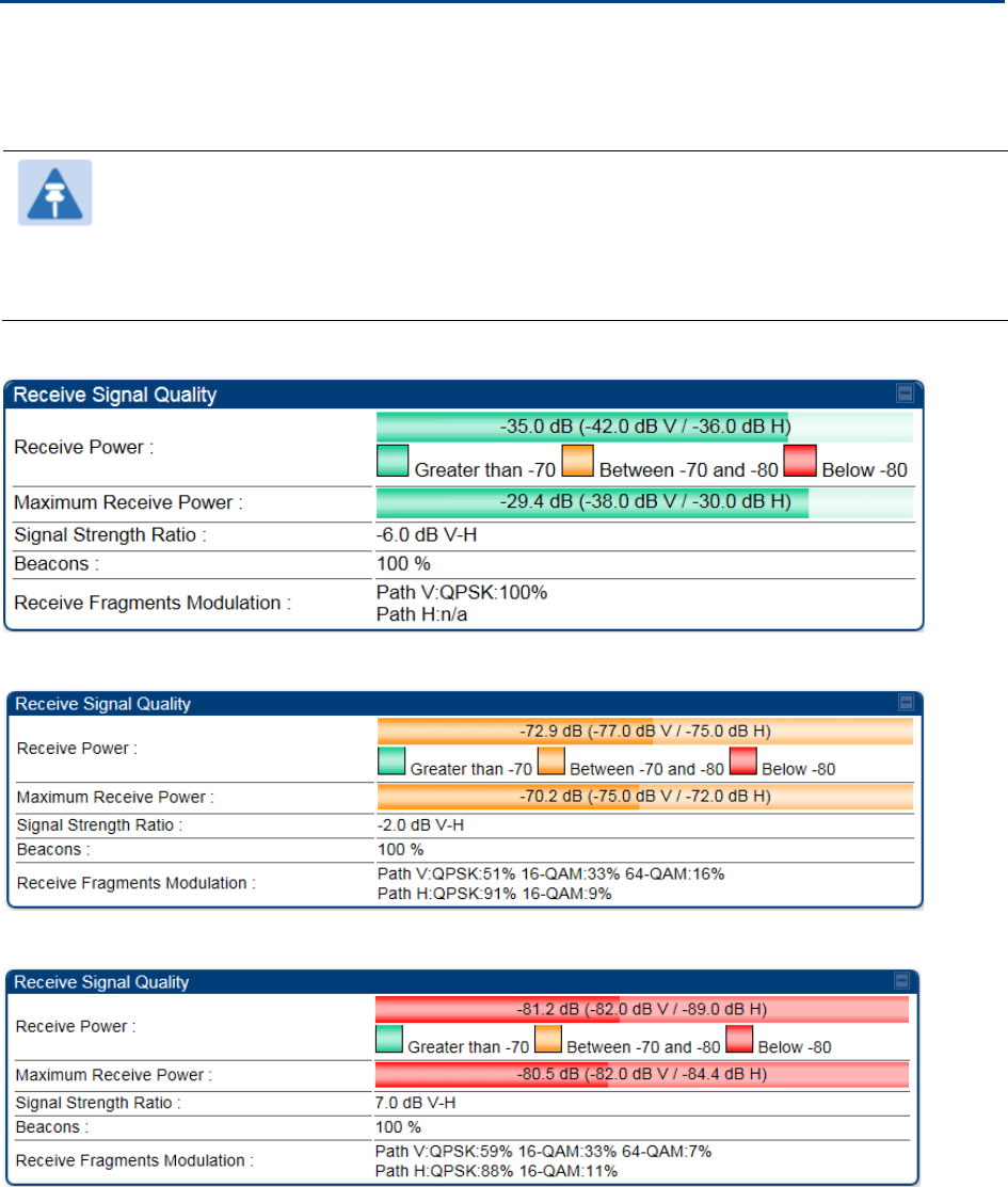
Chapter 8: Tools Using the Alignment Tool
Page 8-15
Using the Alignment Tool
The SM’s or BHS’s Alignment Tool may be used to maximize Receive Power Level, Signal Strength
Ratio and Signal to Noise Ratio to ensure a stable link. The Tool provides color coded readings to
facilitate in judging link quality.
Note
To get best performance of the link, the user has to ensure the maximum Receive
Power Level during alignment by pointing correctly. The proper alignment is
important to prevent interference in other cells. The achieving Receive Power Level
green (>- 70 dBm) is not sufficient for the link.
Figure 135
Alignment Tool tab of SM – Receive Power Level > -70 dBm
Figure 136
Alignment Tool tab of SM – Receive Power Level between -70 to -80 dBm
Figure 137
Alignment Tool tab of SM – Receive Power Level < -80 dBm
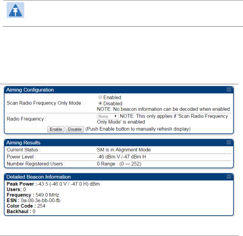
Chapter 8: Tools Using the Alignment Tool
Page 8-16
Alignment Tool and Diagnostic LED – SM/BHS
The SM’s/BHS’s Alignment Tool (located in GUI
Tools ->
Alignment
) may be used to configure the
SM’s/BHS’s LED panel to indicate received signal strength and to display decoded beacon
information/power levels. The SM/BHS LEDs provide different status based on the mode of the
SM/BHS. A SM/BHS in “operating” mode will register and pass traffic normally. A SM/BHS in
“aiming” mode will not register or pass traffic, but will display (via LED panel) the strength of
received radio signals (based on radio channel selected via
Tools
->
Alignment
). To enter “aiming”
mode, configure parameter
Scan Radio Frequency Only Mode
to “Enabled”. See SM/BHS LEDs on
page 2-12.
Note
In order for accurate power level readings to be displayed, traffic must be present on
the radio link.
Refer Table 15 SM/BHS LED descriptions on page 2-13 for SM/BHS LED details.
Alignment page of SM
The Alignment page of SM is explained in Table 160.
Table 160
Alignment page attributes – SM

Chapter 8: Tools Using the Alignment Tool
Page 8-17
Attribute
Meaning
Scan Radio
Frequency Only
Mode
Enabled
: the radio is configured to “aiming” or “alignment” mode,
wherein the LED panel displays an indication of receive power level. See
Table 15 SM/BHS LED descriptions on page 2-13.
Disabled:
the radio is configured to “operating” mode, wherein the SM
registers and passes traffic normally.
Radio Frequency This field indicates the center frequency for which results are displayed.
Current Status This field indicates the current mode of the radio, “alignment” or
“operating”.
Power Level This field indicates the current receive power level (vertical channel) for
the frequency configured in parameter
Radio Frequency
.
Number Registered
Users
When the radio is in “operating” mode, this field reports the number of
registered SMs for the AP operating at the frequency defined in
parameter
Radio Frequency
.
Peak Power This field indicates the highest power level see by the SMs receiver.
Users This field indicates the number of SMs currently registered to the AP
which is transmitting the beacon information.
Frequency This field indicates the frequency of the AP which is transmitting the
beacon information.
ESN This field indicates the MAC, or hardware address of the AP which is
transmitting the beacon information.
Color Code This field displays a value from 0 to 254 indicating the AP’s configured
color code. For registration to occur, the color code of the SM and the AP
must match. Color code is not a security feature. Instead, color code is a
management feature, typically for assigning each sector a different color
code.
Color code allows you to force a SM to register to only a specific AP,
even where the SM can communicate with multiple APs. The default
setting for the color code value is 0. This value matches only the color
code of 0 (not all 255 color codes).
Backhaul
0
indicates that the beacon transmitter is an AP.
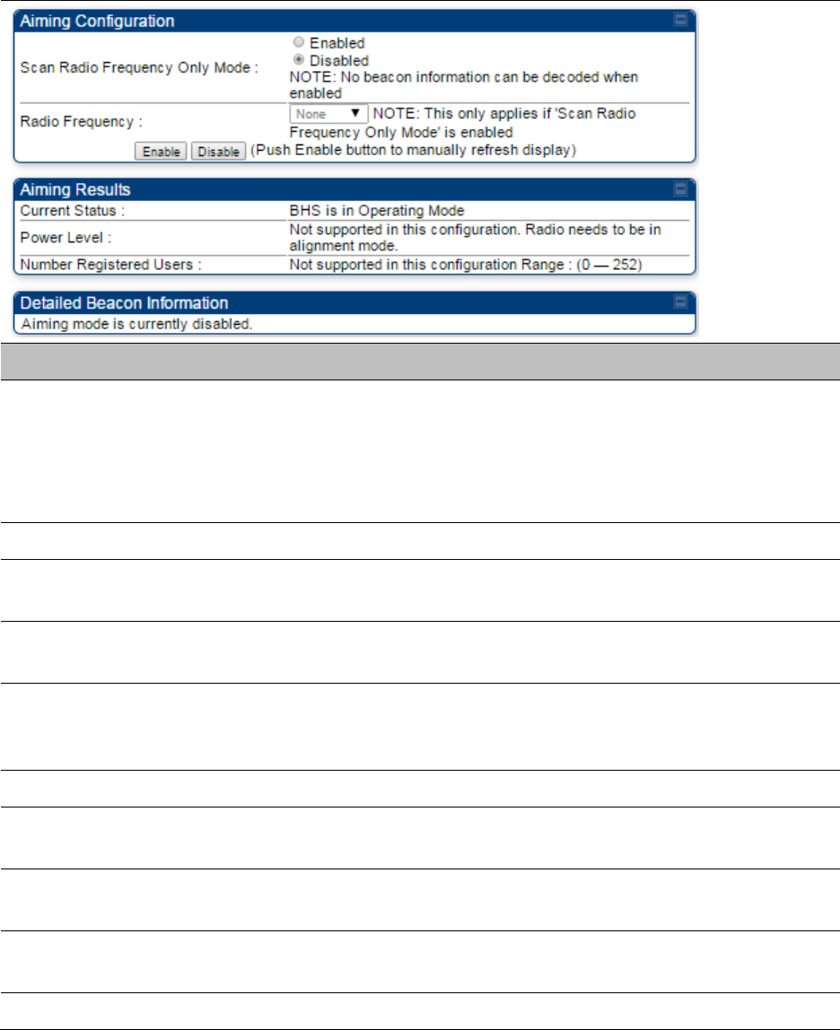
Chapter 8: Tools Using the Alignment Tool
Page 8-18
Alignment page of BHS
The Alignment page of BHS is explained in Table 161.
Table 161
Alignment page attributes - BHS
Attribute
Meaning
Scan Radio
Frequency Only
Mode
Enabled
: the radio is configured to “aiming” or “alignment” mode,
wherein the SM’s LED panel displays an indication of receive power
level. See Table 171 on page 9-7.
Disabled:
the radio is configured to “operating” mode, wherein the SM
registers and passes traffic normally.
Radio Frequency This field indicates the center frequency for which results are displayed.
Current Status This field indicates the current mode of the radio, “alignment” or
“operating”.
Power Level This field indicates the current receive power level (vertical channel) for
the frequency configured in parameter
Radio Frequency
.
Number Registered
Users
When the radio is in “operating” mode, this field reports the number of
registered BHS for the BHM operating at the frequency defined in
parameter
Radio Frequency
.
Peak Power This field indicates the highest power level see by the SMs receiver.
Users This field indicates the number of BHS currently registered to the BHM
which is transmitting the beacon information.
Frequency This field indicates the frequency of the AP which is transmitting the
beacon information.
ESN This field indicates the MAC, or hardware address of the BHM which is
transmitting the beacon information.
Color Code This field displays a value from 0 to 254 indicating the BHM’s configured

Chapter 8: Tools Using the Alignment Tool
Page 8-19
color code. For registration to occur, the color code of the BHS and the
BHM must match. Color code is not a security feature. Instead, color
code is a management feature, typically for assigning each sector a
different color code.
Color code allows you to force a BHS to register to only a specific BHM,
even where the BHS can communicate with multiple APs. The default
setting for the color code value is 0. This value matches only the color
code of 0 (not all 255 color codes).
Backhaul
1
indicates that the beacon transmitter is a BHM.
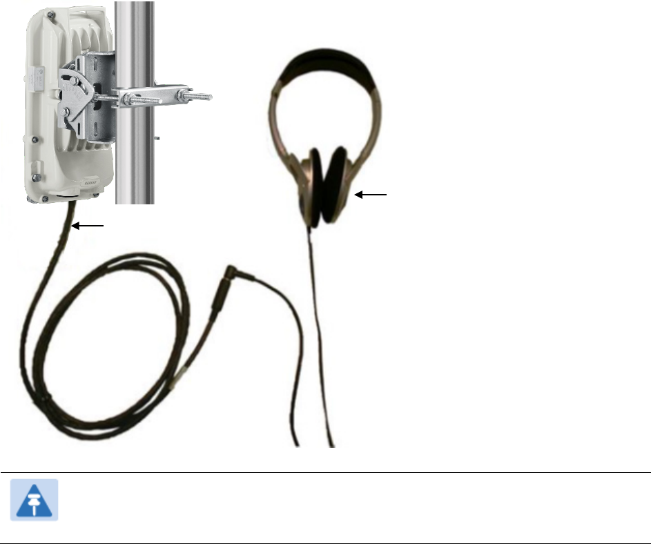
Chapter 8: Tools Using the Alignment Tool
Page 8-20
Alignment Tone
For coarse alignment of the SM/BHS, use the Alignment Tool located at
Tools ->
Alignment Tool
.
Optionally, connect a headset alignment tone kit to the AUX/SYNC port of the SM/BHS and listen
to the alignment tone, which indicates greater SM/BHS receive signal power by pitch. By adjusting
the SM’s/BHS’s position until the highest frequency pitch is obtained operators and installers can
be confident that the SM/BHS is properly positioned. For information on device GUI tools available
for alignment, see sections Alignment Tool and Diagnostic LED – SM/BHS on page 8-16, Using the
Link Capacity Test tool on page 8-21 and Using AP Evaluation tool on page 8-24.
Figure 138
PMP/PTP
450i link alignment tone
Note
The Alignment Tone cable for a 450i uses an RJ-45 to headset cable where the 450
alignment tone cable uses an RJ-12 to headset cable.
Headphones
450i Alignment
tone adapter
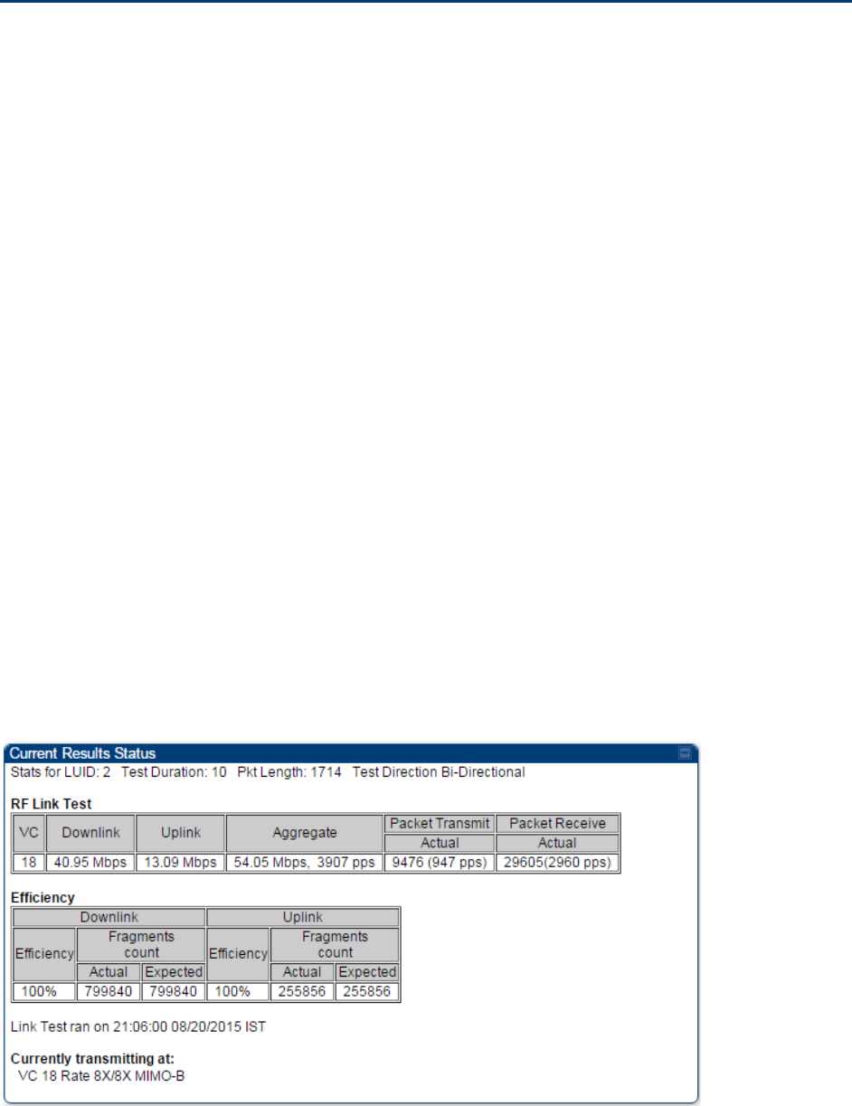
Chapter 8: Tools Using the Link Capacity Test tool
Page 8-21
Using the Link Capacity Test tool
The
Link Capacity Test
tab allows you to measure the throughput and efficiency of the RF link
between two modules. Many factors, including packet length, affect throughput. The
Link Capacity
Test
tab contains the settable parameter
Packet Length
with a range of 64 to 1714 bytes. This
allows you to compare throughput levels that result from various packet sizes.
Performing link capacity test
To run a simple link capacity test that floods the link with 1714 byte packets for 10 seconds,
perform the following procedure:
Procedure 30
Performing a simple Link Capacity Test
1
Access the Link Capacity Test tab in the Tools web page of the module.
2
Select Link Test Mode
Link Test with Bridging
3
Select the subscriber module to test using the Current Subscriber Module parameter.
4
Type into the
Duration
field how long (in seconds) the RF link must be tested.
5
Type into the
Number of Packets
field a value of
0
to flood the link for the duration of
the test.
6
Type into the
Packet Length
field a value of
1714
to send 1714-byte packets during the
test.
7
Click the
Start Test
button.
8
In the Current Results Status block of this tab, view the results of the test. See Figure
139 on page 8-21.
Figure 139
Link Capacity Test tab with 1714-byte packet length
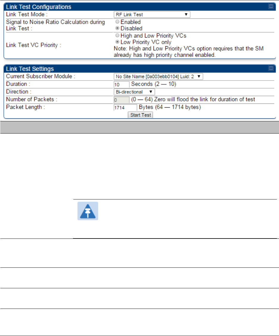
Chapter 8: Tools Using the Link Capacity Test tool
Page 8-22
Link Capacity Test page of AP/SM
The Link Capacity Test page of AP is explained in Table 162.
Table 162
Link Capacity Test page attributes - AP
Attribute
Meaning
Link Test Mode
• RF Link Test: Fully tests radio-to-radio communication, but does not
bridge traffic.
• Link Test with Bridging: Bridges traffic to “simulated” Ethernet ports,
providing a status of the bridged link.
• Link Test with Bridging and MIR: Bridges the traffic during test and
also adheres to any MIR (Maximum Information Rate) settings for
the link.
Note
This mode setting must be equal on both the AP and the
SM when running the link test for proper bridging and MIR
handling.
Signal to Noise Ratio
Calculation during
Link Test
Enable this attribute to display Signal-to-Noise information for the
downlink and uplink when running the link test.
Link Test VC Priority This attribute may be used to enable/disable usage of the high priority
virtual channel during the link test.
Current Subscriber
Module
The SM with which the Link Capacity Test is run. This field is only
applicable for AP (not SM page).
Duration
This field allows operators to configure a specified time for which the
spectrum is scanned. If the entire spectrum is scanned prior to the end of
the configured duration, the analyzer will restart at the beginning of the
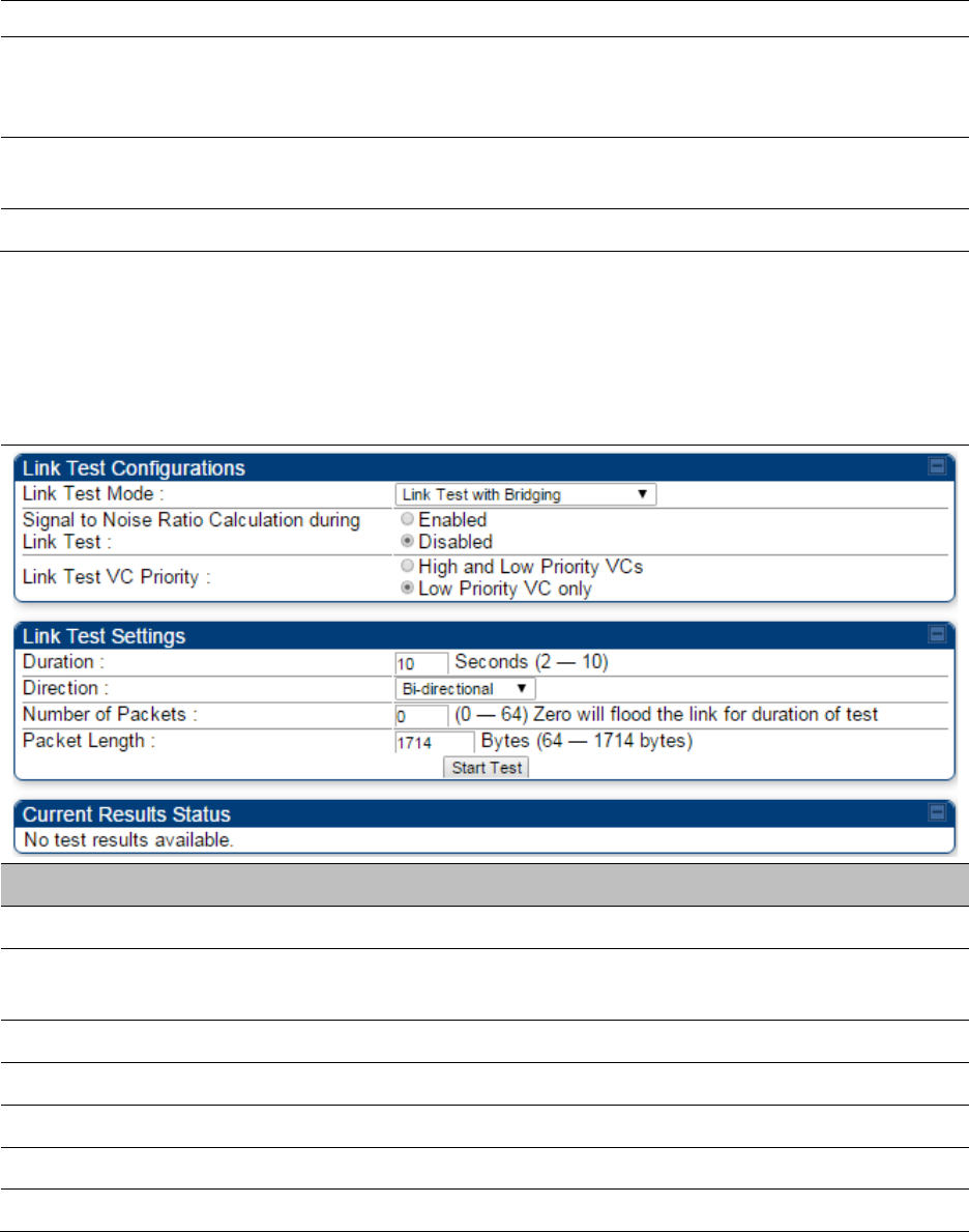
Chapter 8: Tools Using the Link Capacity Test tool
Page 8-23
spectrum.
Direction
Configure the direction of the link test. Specify
Downlink
or
Uplink
to run
the test only in the corresponding direction only. Specific
Bi-Directional
to run the test in both directions.
Number of Packets The total number of packets to send during the Link Capacity Test. When
Link Test Mode is set to
RF Link Test
this field is not configurable.
Packet Length The size of the packets in Bytes to send during the Link Capacity Test
Link Capacity Test page of BHM/BHS
The Link Capacity Test page of BHM/BHS is explained in Table 163.
Table 163
Link Capacity Test page attributes – BHM/BHS
Attribute
Meaning
Link Test Mode See Table 162 on page 8-22
Signal to Noise Ratio Calculation
during Link Test See Table 162 on page 8-22
Link Test VC Priority See Table 162 on page 8-22
Duration See Table 162 on page 8-22
Direction See Table 162 on page 8-22
Number of Packets See Table 162 on page 8-22
Packet Length See Table 162 on page 8-22
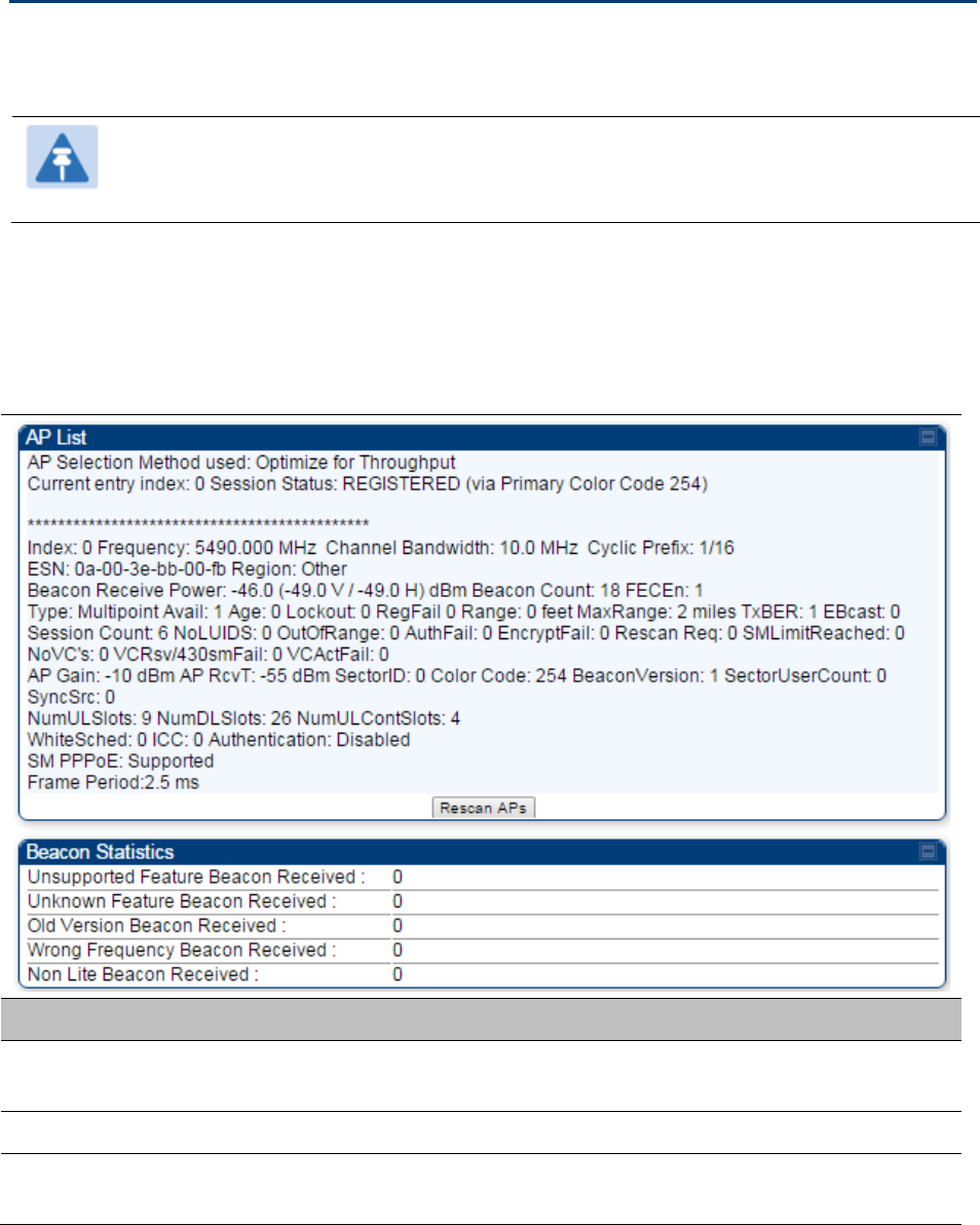
Chapter 8: Tools Using AP Evaluation tool
Page 8-24
Using AP Evaluation tool
The
AP Evaluation
tab on
Tools
web page of the SM provides information about the AP that the
SM sees.
Note
The data for this page may be suppressed by the
SM Display of AP Evaluation Data
setting in the
Configuration > Security
tab of the AP.
AP Evaluation page of AP
The AP Evaluation page of AP is explained in Table 164.
Table 164
AP Evaluation tab attributes - AP
Attribute
Meaning
Index This field displays the index value that the system assigns (for only this
page) to the AP where this SM is registered.
Frequency This field displays the frequency that the AP transmits.
Channel Bandwidth The channel size used by the radio for RF transmission. The setting for
the channel bandwidth must match between the AP and the SM.

Chapter 8: Tools Using AP Evaluation tool
Page 8-25
Cyclic Prefix OFDM technology uses a cyclic prefix, where a portion of the end of a
symbol (slot) is repeated at the beginning of the symbol to allow multi-
pathing to settle before receiving the desired data. A 1/16 cyclic prefixes
mean that for every 16 bits of throughput data transmitted, an additional
bit is used. The Cyclic Prefix 1/16 only can be selected at this time.
ESN This field displays the MAC address (electronic serial number) of the AP.
For operator convenience during SM aiming, this tab retains each
detected ESN for up to 15 minutes. If the broadcast frequency of a
detected AP changes during a 15-minute interval in the aiming
operation, then a multiple instance of the same ESN is possible in the
list. Eventually, the earlier instance expires and disappears and the later
instance remains to the end of its interval, but you can ignore the early
instance(s) whenever two or more are present.
Region This field displays the AP’s configured Country Code setting.
Power Level
This field displays the SM’s combined received power level from the
AP’s transmission.
Beacon Count A count of the beacons seen in a given time period.
FECEn This field contains the SNMP value from the AP that indicates whether
the Forward Error Correction feature is enabled.
0: FEC is disabled
1: FEC is enabled
Type Multipoint indicates that the listing is for an AP.
Age This is a counter for the number of minutes that the AP has been
inactive. At 15 minutes of inactivity for the AP, this field is removed from
the AP Evaluation tab in the SM.
Lockout This field displays how many times the SM has been temporarily locked
out of making registration attempts.
RegFail This field displays how many registration attempts by this SM failed.
Range This field displays the distance in feet for this link. To derive the distance
in meters, multiply the value of this parameter by 0.3048.
MaxRange This field indicates the configured value for the AP’s Max Range
parameter.
TxBER A 1 in this field indicates the AP is sending Radio BER.
EBcast A 1 in this field indicates the AP or BHM is encrypting broadcast packets.
A 0 indicates it is not.
Session Count
This field displays how many sessions the SM (or BHS) has had with the
AP (or BHM). Typically, this is the sum of Reg Count and Re-Reg Count.
However, the result of internal calculation may display here as a value

Chapter 8: Tools Using AP Evaluation tool
Page 8-26
that slightly differs from the sum.
In the case of a multipoint link, if the number of sessions is significantly
greater than the number for other SMs, then this may indicate a link
problem or an interference problem.
NoLUIDs This field indicates how many times the AP has needed to reject a
registration request from a SM because its capacity to make LUID
assignments is full. This then locks the SM out of making any valid
attempt for the next 15 minutes. It is extremely unlikely that a non-zero
number would be displayed here.
OutOfRange This field indicates how many times the AP has rejected a registration
request from a SM because the SM is a further distance away than the
range that is currently configured in the AP. This then locks the SM out
of making any valid attempt for the next 15 minutes.
AuthFail This field displays how many times authentication attempts from this
SM have failed in the AP.
EncryptFail This field displays how many times an encryption mismatch has
occurred between the SM and the AP.
Rescan Req This field displays how many times a re-range request has occurred for
the BHM that is being evaluated in the AP Eval page of a BHS.
SMLimitReached This field displays 0 if additional SMs may be registered to the AP. If a 1
is displayed, the AP will not accept additional SM registrations.
NoVC’s This counter is incremented when the SM is registering to an AP which
determines that no VC resources are available for allocation. This could
be a primary data VC or a high priority data VC.
VCRsvFail This counter is incremented when the SM is registering to an AP which
has a VC resource available for allocation but cannot reserve the
resource for allocation.
VCActFail This counter is incremented when the SM is registering to an AP which
has a VC resource available for allocation and has reserved the VC, but
cannot activate the resource for allocation.
AP Gain This field displays the total external gain (antenna) used by the AP.
RcvT This field displays the AP’s configured receive target for receiving SM
transmissions (this field affects automatic SM power adjust).
Sector ID This field displays the value of the
Sector ID
field that is provisioned for
the AP.
Color Code This field displays a value from 0 to 254 indicating the AP’s configured
color code. For registration to occur, the color code of the SM and the AP
must match. Color code is not a security feature. Instead, color code is a
management feature, typically for assigning each sector a different color

Chapter 8: Tools Using AP Evaluation tool
Page 8-27
code.
Color code allows you to force a SM to register to only a specific AP,
even where the SM can communicate with multiple APs. The default
setting for the color code value is 0. This value matches only the color
code of 0 (not all 255 color codes).
BeaconVersion This field indicates that the beacon is OFDM (value of 1).
Sector User Count This field displays how many SMs are registered on the AP.
NumULHalfSlots This is the number of uplink slots in the frame for this AP.
NumDLHalfSlots This is the number of downlink slots in the frame for this.
NumULContSlots This field displays how many Contention Slots are being used in the
uplink portion of the frame.
WhiteSched Flag to display if schedule whitening is supported via FPGA
ICC This field lists the SMs that have registered to the AP with their
Installation Color Code (ICC),
Primary CC, Secondary CC or Tertiary CC.
SM PPPoE This filed provides information to the user whether the SM is supporting
PPPoE or not.
Frame Period This field displays the configured Frame Period of the radio.
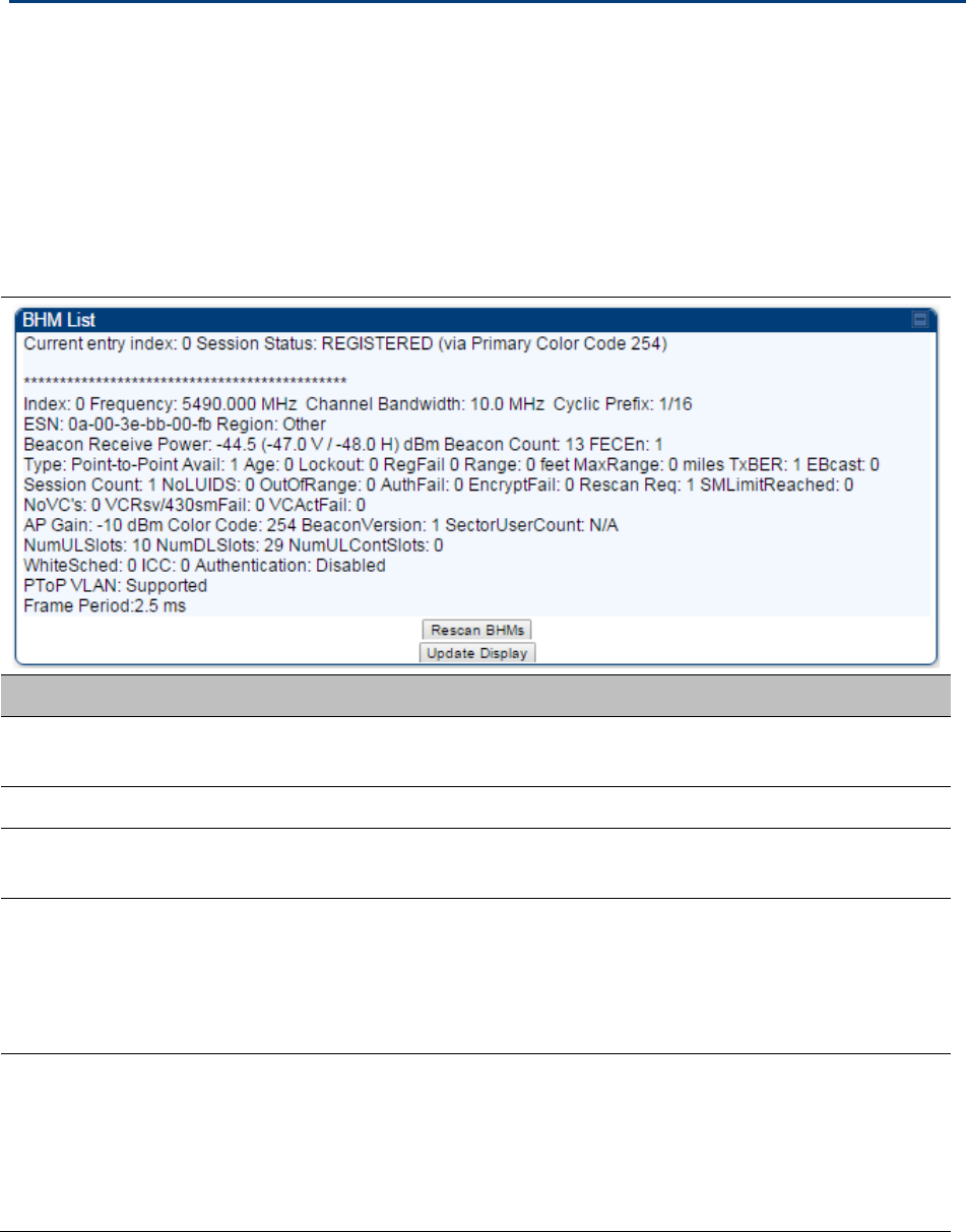
Chapter 8: Tools Using BHM Evaluation tool
Page 8-28
Using BHM Evaluation tool
The
BHM Evaluation
tab on
Tools
web page of the BHS provides information about the BHM that
the BHS sees.
BHM Evaluation page of BHS
The BHM Evaluation page of BHS is explained in Table 165.
Table 165
BHM Evaluation tab attributes - BHS
Attribute
Meaning
Index This field displays the index value that the system assigns (for only this
page) to the BHM where this BHS is registered.
Frequency This field displays the frequency that the BHM transmits.
Channel Bandwidth The channel size used by the radio for RF transmission. The setting for
the channel bandwidth must match between the BHM and the BHS.
Cyclic Prefix OFDM technology uses a cyclic prefix, where a portion of the end of a
symbol (slot) is repeated at the beginning of the symbol to allow multi-
pathing to settle before receiving the desired data. A 1/16 cyclic prefixes
mean that for every 16 bits of throughput data transmitted, an additional
bit is used.
ESN This field displays the MAC address (electronic serial number) of the
BHM. For operator convenience during BHS aiming, this tab retains each
detected ESN for up to 15 minutes. If the broadcast frequency of a
detected BHM changes during a 15-minute interval in the aiming
operation, then a multiple instance of the same ESN is possible in the
list. Eventually, the earlier instance expires and disappears and the later

Chapter 8: Tools Using BHM Evaluation tool
Page 8-29
instance remains to the end of its interval, but you can ignore the early
instance(s) whenever two or more are present.
Region This field displays the BHM’s configured Country Code setting.
Power Level
This field displays the BHS’s combined received power level from the
BHM’s transmission.
Beacon Count A count of the beacons seen in a given time period.
FECEn This field contains the SNMP value from the BHM that indicates whether
the Forward Error Correction feature is enabled.
0: FEC is disabled
1: FEC is enabled
Type Multipoint indicates that the listing is for a BHM.
Age This is a counter for the number of minutes that the BHM has been
inactive. At 15 minutes of inactivity for the BHS, this field is removed
from the BHM Evaluation tab in the BHS.
Lockout This field displays how many times the BHS has been temporarily locked
out of making registration attempts.
RegFail This field displays how many registration attempts by this BHS failed.
Range This field displays the distance in feet for this link. To derive the distance
in meters, multiply the value of this parameter by 0.3048.
MaxRange This field indicates the configured value for the AP’s Max Range
parameter.
TxBER A 1 in this field indicates the BHM is sending Radio BER.
EBcast A 1 in this field indicates the BHM is encrypting broadcast packets. A 0
indicates it is not.
Session Count
This field displays how many sessions the BHS has had with the BHM.
Typically, this is the sum of Reg Count and Re-Reg Count. However, the
result of internal calculation may display here as a value that slightly
differs from the sum.
In the case of a multipoint link, if the number of sessions is significantly
greater than the number for other BHS’s, then this may indicate a link
problem or an interference problem.
NoLUIDs This field indicates how many times the BHM has needed to reject a
registration request from a BHS because its capacity to make LUID
assignments is full. This then locks the BHS out of making any valid
attempt for the next 15 minutes. It is extremely unlikely that a non-zero
number would be displayed here.
OutOfRange This field indicates how many times the BHM has rejected a registration
request from a BHS because the BHS is a further distance away than the

Chapter 8: Tools Using BHM Evaluation tool
Page 8-30
range that is currently configured in the BHM. This then locks the BHS
out of making any valid attempt for the next 15 minutes.
AuthFail This field displays how many times authentication attempts from this
SM have failed in the BHM.
EncryptFail This field displays how many times an encryption mismatch has
occurred between the BHS and the BHM.
Rescan Req This field displays how many times a re-range request has occurred for
the BHM that is being evaluated in the BHM Eval page of a BHM.
SMLimitReached This field displays 0 if additional BHSs may be registered to the BHM. If a
1 is displayed, the BHM will not accept additional BHS registrations.
NoVC’s This counter is incremented when the BHS is registering to a BHM which
determines that no VC resources are available for allocation. This could
be a primary data VC or a high priority data VC.
VCRsvFail This counter is incremented when the BHS is registering to a BHM which
has a VC resource available for allocation but cannot reserve the
resource for allocation.
VCActFail This counter is incremented when the BHS is registering to a BHM which
has a VC resource available for allocation and has reserved the VC, but
cannot activate the resource for allocation.
AP Gain This field displays the total external gain (antenna) used by the BHM.
RcvT This field displays the AP’s configured receive target for receiving BHS
transmissions (this field affects automatic BHS power adjust).
Sector ID This field displays the value of the
Sector ID
field that is provisioned for
the BHM.
Color Code This field displays a value from 0 to 254 indicating the BHM’s configured
color code. For registration to occur, the color code of the BHS and the
BHM must match. Color code is not a security feature. Instead, color
code is a management feature, typically for assigning each sector a
different color code.
Color code allows you to force a BHS to register to only a specific BHM,
even where the BHS can communicate with multiple BHMs. The default
setting for the color code value is 0. This value matches only the color
code of 0 (not all 255 color codes).
BeaconVersion This field indicates that the beacon is OFDM (value of 1).
Sector User Count This field displays how many BHS’s are registered on the BHM.
NumULHalfSlots This is the number of uplink slots in the frame for this BHM.
NumDLHalfSlots This is the number of downlink slots in the frame for this.
NumULContSlots This field displays how many Contention Slots are being used in the

Chapter 8: Tools Using BHM Evaluation tool
Page 8-31
uplink portion of the frame.
WhiteSched Flag to display if schedule whitening is supported via FPGA
ICC This field lists the BHSs that have registered to the BHM with their
Installation Color Code (ICC),
Primary CC, Secondary CC or Tertiary CC.
SM PPPoE This filed provides information to the user whether the BHS is
supporting PPPoE or not.
Frame Period This field displays the configured Frame Period of the radio.

Chapter 8: Tools Using the OFDM Frame Calculator tool
Page 8-32
Using the OFDM Frame Calculator tool
The first step to avoid interference in wireless systems is to set all APs/BHMs to receive timing
from a synchronization source (Cluster Management Module, or Universal Global Positioning
System). This ensures that the modules are in sync and start transmitting at the same time each
frame.
The second step to avoid interference is to configure parameters on all APs/BHMs of the same
frequency band in proximity such that they have compatible transmit/receive ratios (all stop
transmitting each frame before any start receiving). This avoids the problem of one AP/BHM
attempting to receive the signal from a distant SM/BHS while a nearby AP transmits, which could
overpower that signal.
The following parameters on the AP determine the transmit/receive ratio:
• Max Range
• Downlink Data percentage
• (reserved) Contention Slots
If OFDM (PMP 430, PMP 450, PTP 230) and FSK (PMP 1x0) APs/BHMs of the same frequency band
are in proximity, or if APs/BHMs set to different parameters (differing in their Max Range values,
for example), then operator must use the Frame Calculator to identify compatible settings.
The frame calculator is available on the Frame Calculator tab of the Tools web page. To use the
Frame Calculator, type various configurable parameter values into the calculator for each proximal
AP and then record the resulting AP/BHM Receive Start value. Next vary the Downlink Data
percentage in each calculation and iterate until the calculated AP/BHM Receive Start for all
collocated AP/BHMs where the transmit end does not come before the receive start.
The calculator does not use values in the module or populate its parameters. It is merely a
convenience application that runs on a module. For this reason, you can use any FSK module (AP,
SM, BHM, BHS) to perform FSK frame calculations for setting the parameters on an FSK AP and
any OFDM module (AP, SM, BHM, BHS) to perform OFDM frame calculations for setting the
parameters on an OFDM AP/BHM.
For more information on PMP/PTP 450 platform co-location, see
http://www.cambiumnetworks.com/solution-papersThe co-location is also supported for 900 MHz
PMP 450i APs (OFDM) and PMP 100 APps (FSK). Please refer Co-location of PMP 450 and PMP 100
systems in the 900 MHz band and migration recommendations document for details.
Caution
APs/BHMs that have slightly mismatched transmit-to-receive ratios and low levels of
data traffic may see little effect on throughput. A system that was not tuned for co-
location may work fine at low traffic levels, but encounter problems at higher traffic
levels. The conservative practice is to tune for co-location before traffic ultimately
increases. This prevents problems that occur as sectors are built.
The OFDM Frame Calculator page is explained in Table 166.
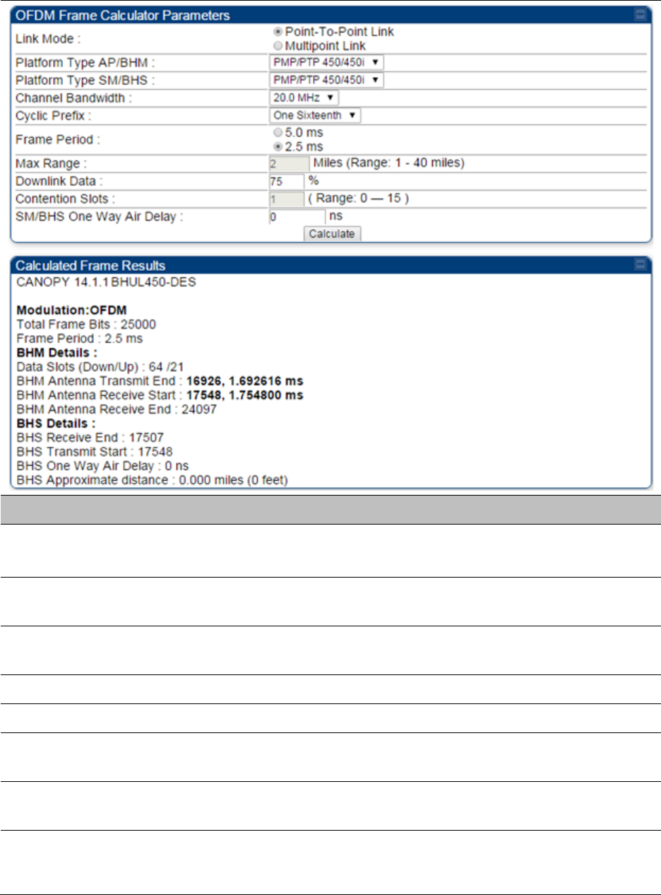
Chapter 8: Tools Using the OFDM Frame Calculator tool
Page 8-33
Table 166
OFDM Frame Calculator page attributes
Attribute
Meaning
Link Mode For AP to SM frame calculations, select
Multipoint Link
For BHM to BHS frame calculations, select
Point-To-Point Link
Platform Type
AP/BHM
Use the drop-down list to select the hardware series (board type) of the
AP/BHM.
Platform Type
SM/BHS
Use the drop-down list to select the hardware series (board type) of the
SM/BHS.
Channel Bandwidth Set this to the channel bandwidth used in the AP/BHM.
Cyclic Prefix Set this to the cyclic prefix used in the AP/BHM.
Max Range Set to the same value as the
Max Range
parameter is set in the AP(s) or
BHM(s).
Frame Period Set to the same value as the
Frame Period
parameter is set in the AP(s)
or BHM(s).
Downlink Data Initially set this parameter to the same value that the AP/BHM has for its
Downlink Data
parameter (percentage). Then, use the Frame Calculator
tool procedure as described in Using the Frame Calculator on page 8-35,

Chapter 8: Tools Using the OFDM Frame Calculator tool
Page 8-34
you will vary the value in this parameter to find the proper value to write
into the
Downlink Data
parameter of all APs or BHMs in the cluster.
PMP 450 platform Series APs or BHMs offer a range of 15% to 85% and
default to 75%. The value that you set in this parameter has the
following interaction with the value of the
Max Range
parameter
(above):
The default
Max Range
value is 5 miles and, at that distance, the
maximum
Downlink Data
value (85% in PMP 450 platform) is functional.
Contention Slots This field indicates the number of (reserved) Contention Slots configured
by the operator. Set this parameter to the value of the
Contention Slot
parameter is set in the APs or BHMs.
SM/BHS One Way
Air Delay
This field displays the time in ns (nano seconds), that a SM/BHS is away
from the AP/BHM.
The Calculated Frame Results display several items of interest:
Table 167
OFDM Calculated Frame Results attributes
Attribute
Meaning
Modulation The type of radio modulation used in the calculation (OFDM for PMP/
PTP 450 platform)
Total Frame Bits The total number of bits used in the calculated frames
Data Slots
(Down/Up)
This field is based on the
Downlink Data
setting. For example, a result
within the typical range for a
Downlink Data
setting of 75% is 61/21,
meaning 61 data slots down and 21 data slots up.
Contention Slots This field indicates the number of (reserved) Contention Slots configured
by the operator.
Air Delay for Max
Range
This is the roundtrip air delay in bit times for the
Max Range
value set in
the calculator
Approximate
distance for Max
Range
The Max Range value used for frame calculation
AP Transmit End In bit times, this is the frame position at which the AP/BHM ceases
transmission.
AP Receive Start In bit times, this is the frame position at which the AP/BHM is ready to
receive transmission from the SM/BHS.
AP Receive End In bit times, this is the frame position at which the AP/BHM will cease
receiving transmission from the SM/BHS.
SM Receive End In bit times, this is the frame position at which the SM/BHS will cease
receiving transmission from the AP/BHM.

Chapter 8: Tools Using the OFDM Frame Calculator tool
Page 8-35
SM Transmit Start In bit times, this is the frame position at which the SM/BHS starts the
transmission.
SM One Way Air
Delay
This filed displays the time in ns, that SM/BHS is away from the AP/BHM.
SM Approximate
distance
This field displays an approximate distance in miles (feet) that the
SM/BHS is away from the AP/BHM.
To use the Frame Calculator to ensure that all APs or BHMs are configured to transmit and receive
at the same time, follow the procedure below:
Procedure 31
Using the Frame Calculator
1
Populate the OFDM Frame Calculator parameters with appropriate values as
described above.
2
Click the
Calculate
button.
3
Scroll down the tab to the Calculated Frame Results section
4
Record the value of the
AP Receive Start
field
5
Enter a parameter set from another AP in the system – for example, an AP in the same
cluster that has a higher
Max Range
value configured.
6
Click the
Calculate
button.
7
Scroll down the tab to the Calculated Frame Results section
8
If the recorded values of the
AP Receive Start
fields are within 150 bit times of each
other, skip to step 10.
If the recorded values of the
AP Receive Start
fields are not within 150 bit times of
each other, modify the
Downlink Data
parameter until the calculated results for
AP
Receive Start
are within 300 bit time of each other, if possible, 150 bit time.
10
Access the Radio tab in the Configuration web page of each AP in the cluster and
change its
Downlink Data
parameter (percentage) to the last value that was used in
the Frame Calculator.
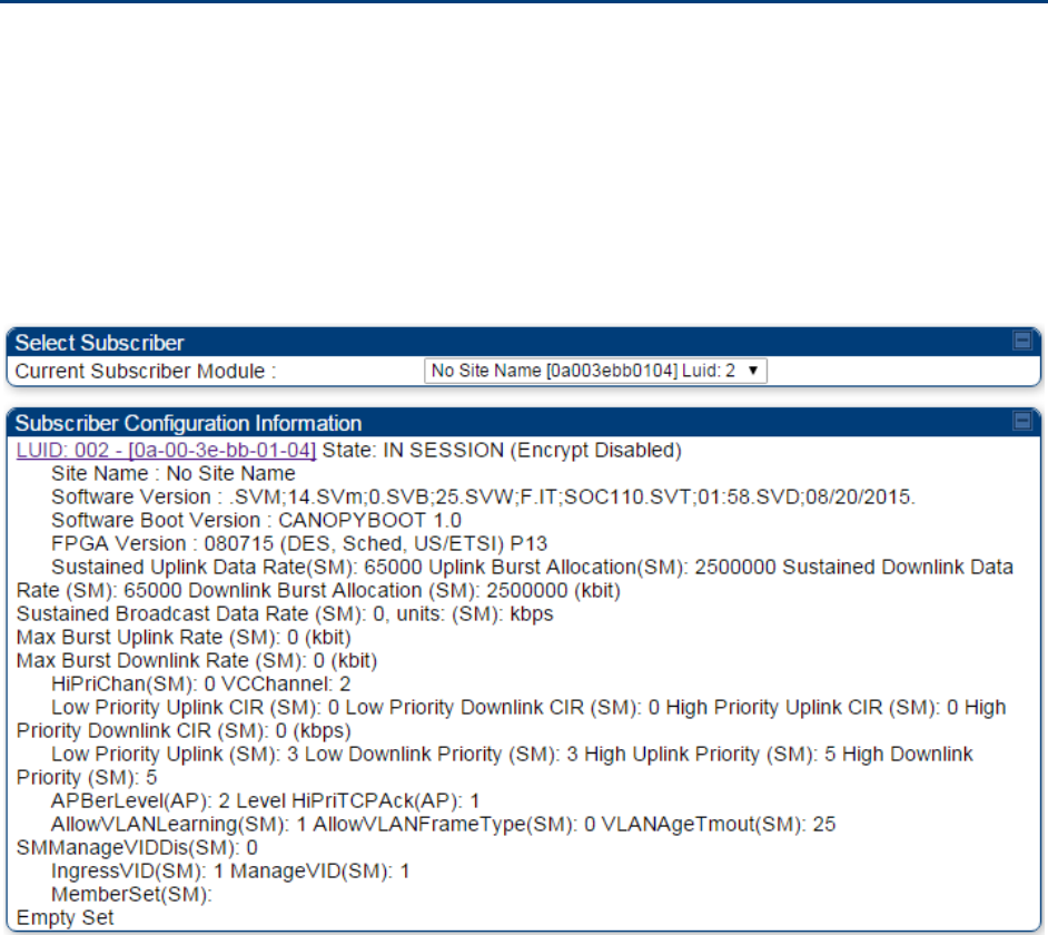
Chapter 8: Tools Using the Subscriber Configuration tool
Page 8-36
Using the Subscriber Configuration tool
The
Subscriber Configuration
page in the Tools page of the AP displays:
• The current values whose control may be subject to the setting in the
Configuration Source
parameter.
• An indicator of the source for each value.
This page may be referenced for information on how the link is behaving based on where the SM
is retrieving certain QoS and VLAN parameters.
Figure 140
SM Configuration page of AP
The AP displays one of the following for the configuration source:
• (SM) – QoS/VLAN parameters are derived from the SM’s settings
• (APCAP) – QoS/VLAN parameters are derived from the AP’s settings, including any keyed
capping (for radios capped at 4 Mbps, 10 Mbps, or 20 Mbps)
• (D) – QoS/VLAN parameters are retrieved from the device, due to failed retrieval from the AAA
or WM server.
• (AAA) – QoS/VLAN parameters are retrieved from the RADIUS server
• (BAM) – QoS/VLAN parameters are retrieved from a WM BAM server
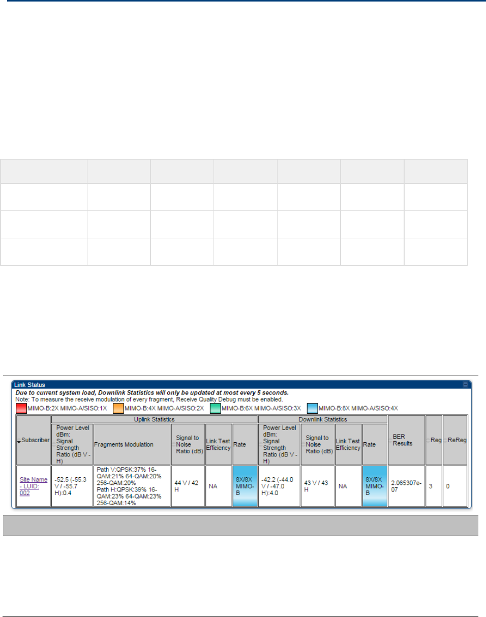
Chapter 8: Tools Using the Link Status tool
Page 8-37
Using the Link Status tool
The Link Status Tool displays information about the most-recent Link Test initiated on the SM or
BHS. Link Tests initiated from the AP or BHM are not included in the Link Status table. This table is
useful for monitoring link test results for all SMs or BHS in the system.
The Link Status table is color coded to display health of link between AP/BHM and SM/BHS. The
current Modulation Level Uplink/Downlink is chosen to determine link health and color coded
accordingly.
Uplink/Downlink Rate Column will be color coded using current Rate as per the table below:
Table 168
Color code vers uplink/downlink rate column
Actual Rate
1x
2x
3x
4x
6x
8x
SISO
RED
ORANGE
GREEN
BLUE
NA
NA
MIMO-A
RED
ORANGE
GREEN
BLUE
NA
NA
MIMO B
NA
RED
NA
ORANGE
GREEN
BLUE
The current Uplink Rate (both low and high VC) for each SM or BHS in Session in now available on
AP or BHM Link Status Page.
The Link Status tool results include values for the following fields.
Table 169
Link Status page attributes - AP
Attribute
Meaning
Subscriber This field displays the LUID (logical unit ID), MAC address and Site Name
of the SM. As each SM registers to the AP, the system assigns an LUID
of 2 or a higher unique number to the SM. If a SM loses registration with
the AP and then regains registration, the SM will retain the same LUID.

Chapter 8: Tools Using the Link Status tool
Page 8-38
Note
The LUID associated is lost when a power cycle of the AP
occurs.
Both the LUID and the MAC are hot links to open the
interface to the SM. In some instances, depending on
network activity and network design, this route to the
interface yields a blank web page. If this occurs, refresh
your browser view.
Site Name indicates the name of the SM. You can assign or
change this name on the Configuration web page of the
SM. This information is also set into the sysName SNMP
MIB-II object and can be polled by an SNMP management
server.
Uplink Statistics -
Power Level: Signal
Strength Ratio
This field represents the combined received power level at the AP/BHM
as well as the ratio of horizontal path signal strength to vertical path
signal strength.
Uplink Statistics –
Fragments
Modulation
This field represents the percentage of fragments received at each
modulation state, per path (polarization).
Uplink Statistics –
Signal to Noise Ratio
This field represents the signal to noise ratio for the uplink (displayed
when parameter Signal to Noise Ratio Calculation during Link Test is
enabled) expressed for both the horizontal and vertical channels.
Uplink Statistics –
Link Test Efficiency
This field displays the efficiency of the radio link, expressed as a
percentage, for the radio uplink.
Downlink Statistics –
Power Level: Signal
Strength Ratio
This field represents the received power level at the SM/BHS as well as
the ratio of horizontal path signal strength to vertical path signal
strength at the SM/BHS.
Downlink Statistics –
Signal to Noise Ratio
This field represents the signal to noise ratio for the downlink (displayed
when parameter Signal to Noise Ratio Calculation during Link Test is
enabled) expressed for both the horizontal and vertical channels.
Downlink Statistics –
Link Test Efficiency
This field displays the efficiency of the radio link, expressed as a
percentage, for the radio downlink.
BER Results This field displays the over-the-air Bit Error Rates for each downlink.
(The ARQ [Automatic Resend reQuest] ensures that the transport BER
[the BER seen end-to-end through a network] is essentially zero.) The
level of acceptable over-the-air BER varies, based on operating
requirements, but a reasonable value for a good link is a BER of 1e-4 (1 x
10-4) or better, approximately a packet resend rate of 5%.
BER is generated using unused bits in the downlink. During periods of
peak load, BER data is not updated as often, because the system puts
priority on transport rather than on BER calculation.

Chapter 8: Tools Using the Link Status tool
Page 8-39
Reg Requests A Reg Requests count is the number of times the SM/BHS registered
after the AP/BHM determined that the link had been down.
If the number of sessions is significantly greater than the number for
other SMs/BHS, then this may indicate a link problem (check mounting,
alignment, receive power levels) or an interference problem (conduct a
spectrum scan).
ReReg Requests A ReReg Requests count is the number of times the AP/BHM received a
SM/BHS registration request while the AP/BHM considered the link to be
still up (and therefore did not expect registration requests).
If the number of sessions is significantly greater than the number for
other SMs/BHS, then this may indicate a link problem (check mounting,
alignment, receive power levels) or an interference problem (conduct a
spectrum scan).
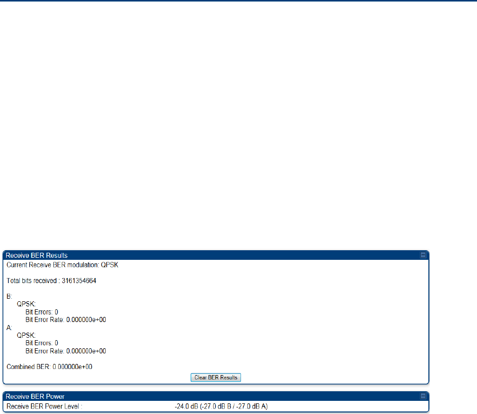
Chapter 8: Tools Using BER Results tool
Page 8-40
Using BER Results tool
Radio BER data represents bit errors at the RF link level. Due to CRC checks on fragments and
packets and ARQ (Automatic Repeat reQuest), the BER of customer data is essentially zero. Radio
BER gives one indication of link quality. Other important indications to consider includes the
received power level, signal to noise ratio and link tests.
BER is only instrumented on the downlink and is displayed on the BER Results tab of the Tools
page in any SM. Each time the tab is clicked, the current results are read and counters are reset to
zero.
The BER Results tab can be helpful in troubleshooting poor link performance.
The link is acceptable if the value of this field is less than 10−4. If the BER is greater than 10−4, re-
evaluate the installation of both modules in the link.
The BER test signal is broadcast by the AP/BHM (and compared to the expected test signal by the
SM/BHS) only when capacity in the sector allows it. This signal is the lowest priority for AP/BHM
transmissions.
Figure 141
BER Results tab of the SM
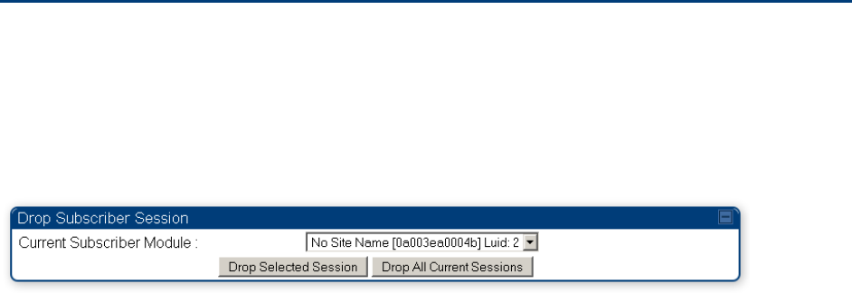
Chapter 8: Tools Using the Sessions tool
Page 8-41
Using the Sessions tool
The PMP 450 platform AP has a tab
Sessions
under the Tools category which allows operators to
drop one or all selected SM sessions and force a SM re-registration. This operation is useful to
force QoS changes for SMs without losing AP logs or statistics. This operation may take 5 minutes
to regain all SM registrations.
Figure 142
Sessions tab of the AP

Page 9-1
Chapter 9: Operation
This chapter provides instructions for operators of the PMP/PTP 450 platform wireless Ethernet
Bridge. The following topics are described in this chapter:
• System information on page 9-2
o Viewing General Status on page 9-2
o Viewing Session Status on page 9-15
o Viewing Remote Subscribers on page 9-20
o Interpreting messages in the Event Log on page 9-20
o Viewing the Network Interface on page 9-23
o Viewing the Layer 2 Neighbors on page 9-24
• System statistics on page 9-25
o Viewing the Scheduler statistics on page 9-25
o Viewing list of Registration Failures statistics on page 9-27
o Interpreting Bridging Table statistics on page 9-28
o Interpreting Translation Table statistics on page 9-29
o Interpreting Ethernet statistics on page 9-30
o Interpreting RF Control Block statistics on page 9-33
o Interpreting VLAN statistics on page 9-34
o Interpreting Data VC statistics on page 9-36
o Interpreting Throughput statistics on page 9-38
o Interpreting Overload statistics on page 9-41
o Interpreting DHCP Relay statistics on page 9-42
o Interpreting Filter statistics on page 9-43
o Viewing ARP statistics on page 9-44
o Viewing NAT statistics on page 9-45
o Viewing NAT DHCP Statistics on page 9-47
o Interpreting Sync Status statistics on page 9-48
o Interpreting PPPoE Statistics for Customer Activities on page 9-49
o Interpreting Bridge Control Block statistics on page 9-50
o Interpreting Pass Through Statistics on page 9-52
o Interpreting SNMPv3 Statistics on page 9-53
o Interpreting syslog statistics on page 9-55
o Interpreting Frame Utilization statistics on page 9-55
• Radio Recovery on page 9-59

Chapter 9: Operation System information
Page 9-2
System information
This section describes how to use the summary and status pages to monitor the status of the
Ethernet ports and wireless link.
• Viewing General Status on page 9-2
• Viewing Session Status on page 9-15
• Viewing Remote Subscribers on page 9-20
• Interpreting messages in the Event Log on page 9-20
• Viewing the Network Interface on page 9-23
• Viewing the Layer 2 Neighbors on page 9-24
Viewing General Status
The
General Status
tab provides information on the operation of this AP/BHM and SM/BHS. This is
the page that opens by default when you access the GUI of the radio.
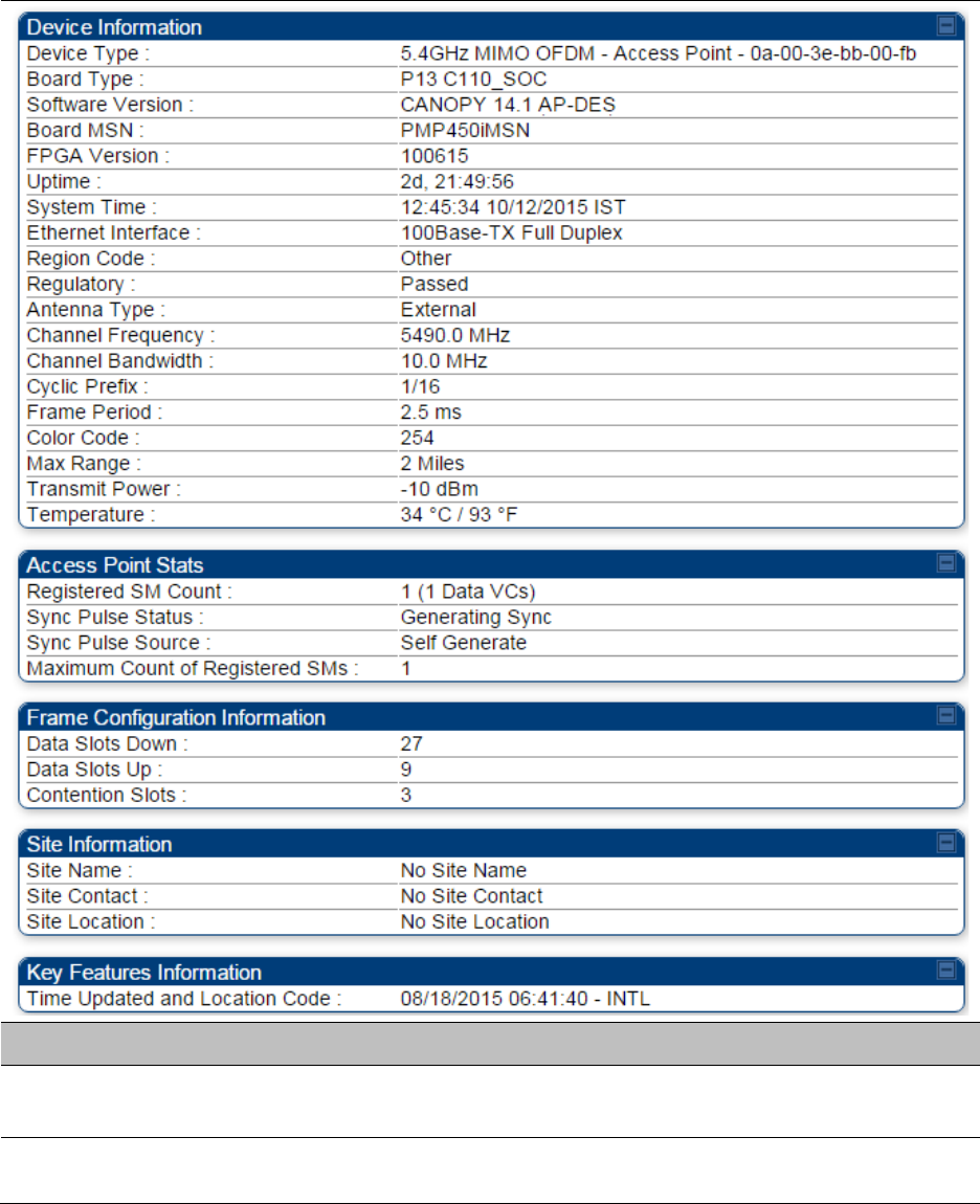
Chapter 9: Operation System information
Page 9-3
General Status page of AP
The AP’s
General Status
page is explained in Table 170.
Table 170
General Status page attributes - AP
Attribute
Meaning
Device Type This field indicates the type of the module. Values include the frequency
band of the SM, its module type and its MAC address.
Software Version This field indicates the system release, the time and date of the release
and whether communications involving the module are secured by DES

Chapter 9: Operation System information
Page 9-4
or AES encryption. If you request technical support, provide the
information from this field.
Board Type This field indicates the series of hardware.
Combo Radio Mode This field indicates the mode of operation, currently only ‘MIMO OFDM
Only’ is supported.
FPGA Version This field indicates the version of the field-programmable gate array
(FPGA) on the module. If you request technical support, provide the
value of this field.
FPGA Type Where the type of logic as a subset of the logic version in the module as
manufactured distinguishes its circuit board, this field is present to
indicate that type. If you request technical support, provide the value of
this field.
PLD Version This field indicates the version of the programmable logic device (PLD)
on the module. If you request technical support, provide the value of this
field.
Uptime This field indicates how long the module has operated since power was
applied.
System Time This field provides the current time. If the AP is connected to a CMM4,
then this field provides GMT (Greenwich Mean Time). Any SM that
registers to the AP inherits the system time.
Last NTP Time
Update
This field displays when the AP last used time sent from an NTP server.
If the AP has not been configured in the Time tab of the Configuration
page to request time from an NTP server, then this field is populated by
00:00:00 00/00/00.
Ethernet Interface This field indicates the speed and duplex state of the Ethernet interface
to the AP.
Regulatory
This field indicates whether the configured
Country Code
and radio
frequency are compliant with respect to their compatibility. PMP 450
equipment shipped to the United States is locked to a Country Code
setting of “United States”. Units shipped to regions other than the
United States must be configured with the corresponding Country Code
to comply with local regulatory requirements.
Channel Center
Frequency
This field indicates the current operating center frequency, in MHz.
Channel Bandwidth This field indicates the current size of the channel band used for radio
transmission.
Cyclic Prefix OFDM technology uses a cyclic prefix, where a portion of the end of a
symbol (slot) is repeated at the beginning of the symbol to allow multi-
pathing to settle before receiving the desired data. A 1/16 cyclic prefix
means that for every 16 bits of throughput data transmitted, an
Chapter 9: Operation System information
Page 9-5
additional bit is used.
Frame Period This field indicates the current Frame Period setting of the radio in ms.
Color Code This field displays a value from 0 to 254 indicating the AP’s configured
color code. For registration to occur, the color code of the SM and the AP
must match. Color code is not a security feature. Instead, color code is a
management feature, typically for assigning each sector a different color
code.
Color code allows you to force a SM to register to only a specific AP,
even where the SM can communicate with multiple APs. The default
setting for the color code value is 0. This value matches only the color
code of 0 (not all 255 color codes).
Max Range This field indicates the setting of the Max Range parameter, which
contributes to the way the radio transmits. Verify that the Max Range
parameter is set to a distance slightly greater than the distance between
the AP and the furthest SM that must register to this AP.
Transmitter Output
Power
This field indicates the combined power level at which the AP is set to
transmit, based on the Country Code and Antenna Gain settings.
Temperature This field indicates the current operating temperature of the device
board.
Registered SM Count This field indicates how many SMs are registered to the AP.
Sync Pulse Status
This field indicates the status of synchronization as follows:
Generating Sync
indicates that the module is set to generate the sync
pulse.
Receiving Sync
indicates that the module is set to receive a sync pulse
from an outside source and is receiving the pulse.
No Sync Since Boot up / ERROR: No Sync Pulse
indicates that the
module is set to receive a sync pulse from an outside source and is not
receiving the pulse.
Note
When this message is displayed, the AP transmitter is
turned off to avoid self-interference within the system.
Sync Pulse Source This field indicates the status of the synchronization source:
Searching
indicates that the unit is searching for a GPS fix
Timing Port/UGPS
indicates that the module is receiving sync via the
timing AUX/SYNC timing port
Power Port
indicates that the module is receiving sync via the power
port (Ethernet port).
On-board GPS
indicates that the module is receiving sync via the unit’s
internal GPS module

Chapter 9: Operation System information
Page 9-6
Maximum Count of
Registered SMs
This field displays the largest number of SMs that have been
simultaneously registered in the AP since it was last rebooted. This
count can provide some insight into sector history and provide
comparison between current and maximum SM counts at a glance.
Data Slots Down This field indicates the number of frame slots that are designated for use
by data traffic in the downlink (sent from the AP to the SM). The AP
calculates the number of data slots based on the
Max Range
,
Downlink
Data
and (reserved)
Contention Slots
configured by the operator.
Data Slots Up
This field indicates the number of frame slots that are designated for use
by data traffic in the uplink (sent from the SM to the AP). The AP
calculates the number of data slots based on the Max Range, Downlink
Data and (reserved) Contention Slots configured by the operator.
Contention Slots This field indicates the number of (reserved) Contention Slots configured
by the operator. See Contention slots on page7-165.
Site Name This field indicates the name of the physical module. You can assign or
change this name in the SNMP tab of the AP Configuration page. This
information is also set into the sysName SNMP MIB-II object and can be
polled by an SNMP management server.
Site Contact This field indicates contact information for the physical module. You can
provide or change this information in the SNMP tab of the AP
Configuration page. This information is also set into the sysName SNMP
MIB-II object and can be polled by an SNMP management server.
Site Location This field indicates site information for the physical module. You can
provide or change this information in the SNMP tab of the AP
Configuration page.
Time Updated and
Location Code
This field displays information about the keying of the radio.
General Status page - SM
The SM’s
General Status
page is explained in Table 171.
Note
In order for accurate power level readings to be displayed, traffic must be present on
the radio link.
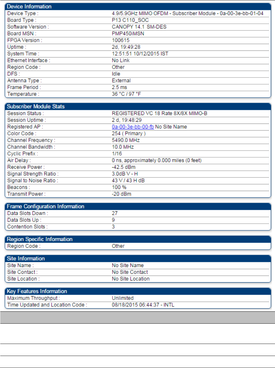
Chapter 9: Operation System information
Page 9-7
Table 171
General Status page attributes - SM
Attribute
Meaning
Device Type This field indicates the type of the module. Values include the frequency
band of the SM, its module type and its MAC address.
Board Type This field indicates the series of hardware.
Software Version This field indicates the system release, the time and date of the release.

Chapter 9: Operation System information
Page 9-8
If you request technical support, provide the information from this field.
FPGA Version This field indicates the version of the field-programmable gate array
(FPGA) on the module. When you request technical support, provide the
information from this field.
PLD Version This field indicates the version of the programmable logic device (PLD)
on the module. If you request technical support, provide the value of this
field.
Uptime This field indicates how long the module has operated since power was
applied.
System Time This field provides the current time. Any SM that registers to an AP
inherits the system time, which is displayed in this field as GMT
(Greenwich Mean Time).
Ethernet Interface This field indicates the speed and duplex state of Ethernet interface to
the SM.
Regional Code
A parameter that offers multiple fixed selections, each of which
automatically implements frequency band range restrictions for the
selected region. Units shipped to regions other than the United States
must be configured with the corresponding Country Code to comply
with local regulatory requirements.
DFS This field indicates that DFS operation is enabled based on the
configured region code, if applicable.
Antenna Type The current antenna type that has been selected.
Frame Period This field indicates the current Frame Period setting of the radio in ms.
Temperature The current operating temperature of the board.
Session Status
This field displays the following information about the current session:
Scanning
indicates that this SM currently cycles through the radio
frequencies that are selected in the Radio tab of the Configuration page.
Syncing
indicates that this SM currently attempts to receive sync.
Registering
indicates that this SM has sent a registration request
message to the AP and has not yet received a response.
Registered
indicates that this SM is both:
• registered to an AP.
• ready to transmit and receive data packets.
Session Uptime This field displays the duration of the current link. The syntax of the
displayed time is hh:mm:ss.
Registered AP Displays the MAC address and site name of the AP to which the SM is
registered to. This parameter provides click-through proxy access to the
AP’s management interface.

Chapter 9: Operation System information
Page 9-9
Color Code This field displays a value from 0 to 254 indicating the SM’s configured
color code. For registration to occur, the color code of the SM and the AP
must match. Color code is not a security feature. Instead, color code is a
management feature, typically for assigning each sector a different color
code.
Color code allows you to force a SM to register to only a specific AP,
even where the SM can communicate with multiple APs. The default
setting for the color code value is 0. This value matches only the color
code of 0 (not all 255 color codes).
Channel Frequency This field lists the current operating frequency of the radio.
Channel Bandwidth The size in MHz of the operating channel.
Cyclic Prefix OFDM technology uses a cyclic prefix, where a portion of the end of a
symbol (slot) is repeated at the beginning of the symbol to allow multi-
pathing to settle before receiving the desired data. A 1/16 cyclic prefix
means that for every 16 bits of throughput data transmitted, an
additional bit is used.
Air Delay This field displays the distance in feet between this SM and the AP. To
derive the distance in meters, multiply the value of this parameter by
0.3048. Distances reported as less than 200 feet (61 meters) are
unreliable.
Receive Power This field lists the current combined receive power level, in dBm.
Signal Strength
Ratio
This field displays the difference of the Vertical path received signal
power to the Horizontal path received signal power.
Signal to Noise Ratio This field lists the current signal-to-noise level, an indication of the
separation of the received power level vs. noise floor.
Beacons Displays a count of beacons received by the SM in percentage. This
value must be typically between 99-100%. If lower than 99%, it indicates
a problematic link. This statistic is updated every 16 seconds.
Transmit Power This field lists the current combined transmit power level, in dBm.
Data Slots Down This field lists the number of slots used for downlink data transmission.
Data Slots Up This field lists the number of slots used for uplink data transmission.
Contention Slots This field indicates the number of (reserved) Contention Slots configured
by the operator. See Contention slots on page7-165.
Site Name This field indicates the name of the physical module. You can assign or
change this name in the SNMP tab of the SM Configuration page. This
information is also set into the sysName SNMP MIB-II object and can be
polled by an SNMP management server.
Site Contact This field indicates contact information for the physical module. You can
provide or change this information in the SNMP tab of the SM

Chapter 9: Operation System information
Page 9-10
Configuration page. This information is also set into the sysName SNMP
MIB-II object and can be polled by an SNMP management server.
Site Location This field indicates site information for the physical module. You can
provide or change this information in the SNMP tab of the SM
Configuration page.
Maximum
Throughput
This field indicates the limit of aggregate throughput for the SM and is
based on the default (factory) limit of the SM and any floating license
that is currently assigned to it.
Time Updated and
Location Code
This field displays information about the keying of the radio.
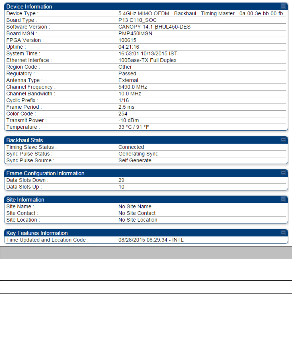
Chapter 9: Operation System information
Page 9-11
General Status page of BHM
The BHM’s
General Status
page is explained in Table 172.
Table 172
General Status page attributes - BHM
Attribute
Meaning
Device Type This field indicates the type of the module. Values include the frequency
band of the BHM, its module type and its MAC address.
Board Type This field indicates the series of hardware.
Software Version This field indicates the system release, the time and date of the release.
If you request technical support, provide the information from this field.
Board MSN This field indicates the Manufacture’s Serial number. A unique serial
number assigned to each radio at the factory for inventory and quality
control.
FPGA Version This field indicates the version of the field-programmable gate array

Chapter 9: Operation System information
Page 9-12
(FPGA) on the module. When you request technical support, provide the
information from this field.
Uptime This field indicates how long the module has operated since power was
applied.
System Time This field provides the current time. Any BHS that registers to a BHM
inherits the system time, which is displayed in this field as GMT
(Greenwich Mean Time).
Ethernet Interface This field indicates the speed and duplex state of Ethernet interface to
the BHM.
Antenna Type The current antenna type that has been selected.
Temperature The current operating temperature of the board.
Session Status
This field displays the following information about the current session:
Scanning
indicates that this BHS currently cycles through the radio
frequencies that are selected in the Radio tab of the Configuration page.
Syncing
indicates that this BHM currently attempts to receive sync.
Registering
indicates that this BHM has sent a registration request
message to the BHM and has not yet received a response.
Registered
indicates that this BHM is both:
• Registered to a BHM.
• Ready to transmit and receive data packets.
Session Uptime This field displays the duration of the current link. The syntax of the
displayed time is hh:mm:ss.
Registered Backhaul Displays the MAC address and site name of the BHM to which the BHS is
registered to. This parameter provides click-through proxy access to the
BHM’s management interface.
Channel Frequency This field lists the current operating frequency of the radio.
Receive Power This field lists the current combined receive power level, in dBm.
Signal Strength
Ratio
This field displays the difference of the Vertical path received signal
power to the Horizontal path received signal power.
Transmit Power This field lists the current combined transmit power level, in dBm.
Signal to Noise Ratio This field lists the current signal-to-noise level, an indication of the
separation of the received power level vs. noise floor.
Beacons Displays a count of beacons received by the BHM in percentage. This
value must be typically between 99-100%. If lower than 99%, it indicates
a problematic link. This statistic is updated every 16 seconds.
Air Delay This field displays the distance in feet between this BHS and the BHM.
To derive the distance in meters, multiply the value of this parameter by

Chapter 9: Operation System information
Page 9-13
0.3048. Distances reported as less than 200 feet (61 meters) are
unreliable.
Data Slots Down This field lists the number of slots used for downlink data transmission.
Data Slots Up This field lists the number of slots used for uplink data transmission.
Regional Code
A parameter that offers multiple fixed selections, each of which
automatically implements frequency band range restrictions for the
selected region. Units shipped to regions other than the United States
must be configured with the corresponding Country Code to comply
with local regulatory requirements.
Site Name This field indicates the name of the physical module. Assign or change
this name in the
Configuration > SNMP
page. This information is also set
into the sysName SNMP MIB-II object and can be polled by an SNMP
management server.
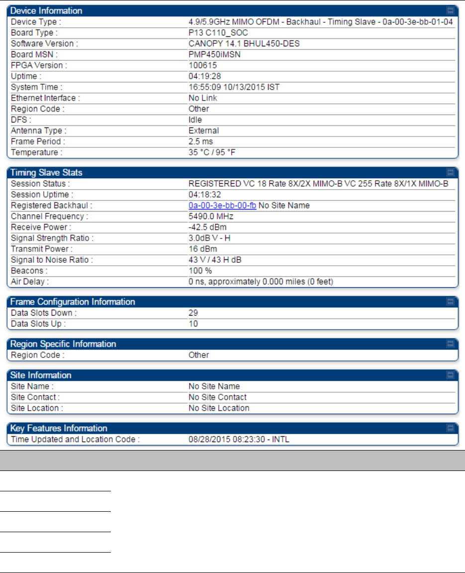

Chapter 9: Operation System information
Page 9-15
Uptime
See Table 173 on page 9-14
System Time
Ethernet Interface
Antenna Type
Temperature
Session Status
Session Uptime
Registered Backhaul
Channel Frequency
Receive Power
Signal Strength
Ratio
Transmit Power
Signal to Noise Ratio
Beacons
Air Delay
Data Slots Down
Data Slots Up
Regional Code
Site Name
Site Contact
Site Location
Time Updated and
Location Code
Viewing Session Status
The
Session Status
page in the Home page provides information about each SM or BHS that has
registered to the AP or BHM. This information is useful for managing and troubleshooting a
system. This page also includes the current active values on each SM or BHS for MIR and VLAN, as
well as the source of these values, representing the SM/BHS itself, Authentication Server, or the
Authentication Server and SM/BHS.
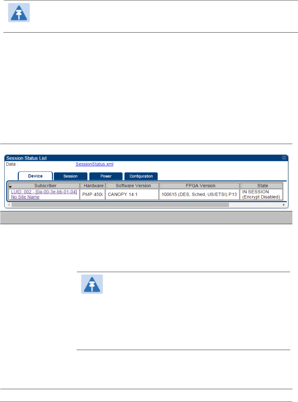
Chapter 9: Operation System information
Page 9-16
Note
In order for accurate power level readings to be displayed, traffic must be present on
the radio link.
The Session Status List has four tab: Device, Session, Power and Configuration.
The SessionStatus.xml hyper link allows user to export session status page from web
management interface of AP or BHM. The session status page will be exported in xml file.
Device tab
The Device tab provides information on the Subscriber’s LUID and MAC, Hardware, Software,
FPGA versions and the state of the SM/BHS (Registered and/or encrypted).
Table 174
Device tab attributes
Attribute
Meaning
Subscriber This field displays the LUID (logical unit ID), MAC address and Site Name
of the SM/BHS. As each SM or BHS registers to the AP/BHM, the system
assigns an LUID of 2 or a higher unique number to the SM/BHS. If a
SM/BHS loses registration with the AP/BHS and then regains
registration, the SM/BHS will retain the same LUID.
Note
The LUID associated is lost when a power cycle of the
AP/BHM occurs.
Both the LUID and the MAC are hot links to open the
interface to the SM/BHS. In some instances, depending on
network activity and network design, this route to the
interface yields a blank web page. If this occurs, refresh
your browser view.
Site Name indicates the name of the SM/BHS. Change this name on the
Configuration web page of the SM/BHS. This information is also set into
the sysName SNMP MIB-II object and can be polled by an SNMP
management server.
Hardware This field displays the SMs or BHS hardware type.
Chapter 9: Operation System information
Page 9-17
Software Version This field displays the software release that operates on the SM/BHS, the
release date and time of the software.
FPGA Version This field displays the version of FPGA that runs on the SM/BHS
State
This field displays the current status of the SM/BHS as either
IN SESSION
to indicate that the SM/BHS is currently registered to the
AP/BHM.
IDLE
to indicate that the SM/BHS was registered to the AP/BHM at one
time, but now is not.
This field also indicates whether the encryption scheme in the module is
enabled.
Session tab
The Session tab provides information on the SMs or BHS Session Count, Reg Count, Re-Reg
Count, Uptime, Air delay, PPPoE State and Timeouts.
Table 175
Session tab attributes
Attribute
Meaning
Subscriber See Table 174 on page 9-16.
Count This field displays how many sessions the SM/BHS has had with the
AP/BHM. Typically, this is the sum of Reg Count and Re-Reg Count.
However, the result of internal calculation may display here as a value
that slightly differs from the sum.
If the number of sessions is significantly greater than the number for
other SMs or BHS, then this may indicate a link problem or an
interference problem.
Reg Count When a SM/BHS makes a registration request, the AP/BHM checks its
local data to see whether it considers the SM/BHS to be already
registered. If the AP/BHM concludes that the SM/BHS is not, then the
request increments the value of this field.
If the number of sessions is significantly greater than the number for
other SMs or BHS, then this may indicate a link problem (check
mounting, alignment, receive power levels) or an interference problem
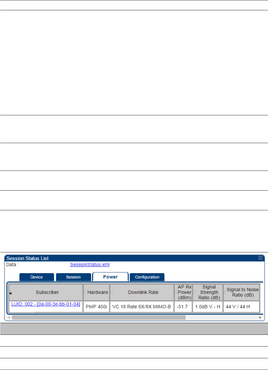
Chapter 9: Operation System information
Page 9-18
(conduct a spectrum scan).
Re-Reg Count
When a SM/BHS makes a registration request, the AP/BHM checks its
local data to see whether it considers the SM/BHS to be already
registered. If the AP/BHM concludes that the SM/BHS is not, then the
request increments the value of this field. Typically, a Re-Reg is the case
where both:
• SM/BHS attempts to reregister for having lost communication with
the AP/BHM.
• AP/BHM has not yet observed the link to the SM/BHS as being down.
If the number of sessions is significantly greater than the number for
other SMs or BHS, then this may indicate a link problem (check
mounting, alignment, receive power levels) or an interference problem
(conduct a spectrum scan).
Uptime Once a SM/BHS successfully registers to an AP/BHM, this timer is
started. If a session drops or is interrupted, this timer is reactivated once
re-registration is complete.
AirDelay This field displays the distance of the SM/BHS from the AP/BHM in
meters, nanoseconds and bits. At close distances, the value in this field
is unreliable.
PPPoE state This field displays the current PPPoE state (whether configured) of the
SM/BHS.
Timeout This field displays the timeout in seconds for management sessions via
HTTP, ftp access to the SM/BHS. 0 indicates that no limit is imposed.
Power tab
Table 176
Power tab attributes
Attribute
Meaning
Subscriber See Table 174 on page 9-16.
Hardware This field displays the SMs or BHS hardware type.
Rate This field displays whether the high-priority channel is enabled in the
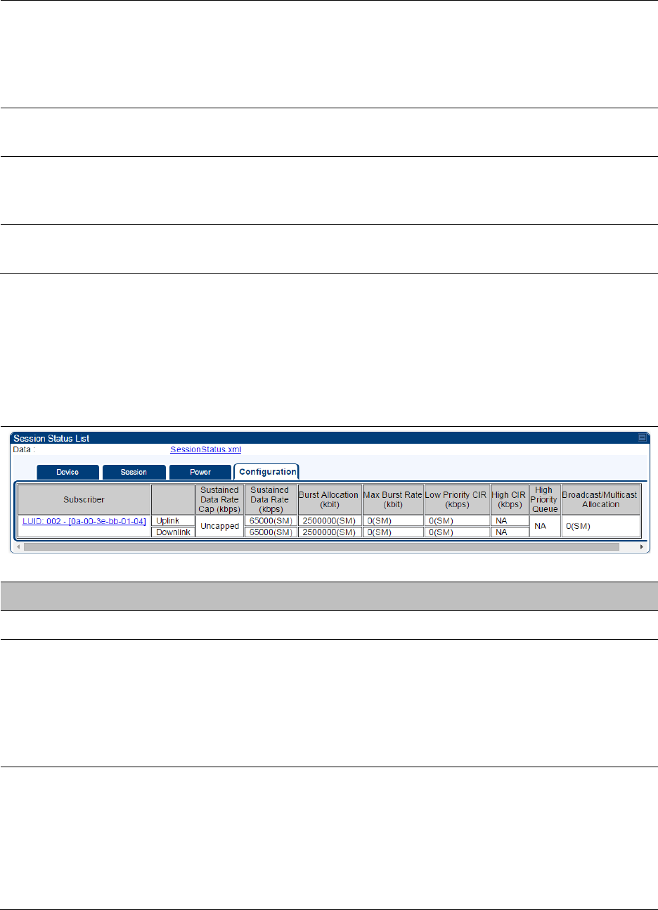
Chapter 9: Operation System information
Page 9-19
SM/BHS and the status of rate adapt. For example, if “8X/4X” is listed,
the radio is capable of operating at 8X but is currently operating at 4X,
due to RF conditions.
This field also states whether it is MIMO-A or MIMO-B radio e.g. “8X/8X
MIMO-B” indicates MIMO-B and “8X/4X MIMO-A” indicates MIMO-A.
AP Receive Power
Level
This field indicates the AP’s or BHM’s combined receive power level for
the listed SM/BHS.
Signal Strength
Ratio
This field displays the ratio of the Vertical path received signal power to
the Horizontal path received signal power. This ratio can be useful for
determining multipathing conditions (high vertical to horizontal ratio).
Signal to Noise Ratio This field lists the current signal-to-noise level, an indication of the
separation of the received power level vs. noise floor.
Configuration tab
The
Configuration
tab provides information on the SMs or BHS Uplink or Downlink (UL/DL)
Sustained Data Rate, UL/DL Burst Allocation, UL/DL Burst Rate, UL/DL Low Priority CIR, UL/DL High
CIR, UL/DL High Priority Queue Information and the UL/DL Broadcast or Multicast Allocation. This
data is refreshed based on the Web Page Auto Update setting on the AP’s or BHS’s General
Configuration page.
Table 177
Configuration tab attributes
Attribute
Meaning
Subscriber See Table 174 on page 9-16.
Sustained Data Rate This field displays the CIR value in kbps that is currently in effect for the
SM/BHS in both the Uplink and Downlink direction. In the Uplink, this is
the specified rate at which each SM/BHS registered to this AP/BHM is
replenished with credits for transmission. In the Downlink, this is the
specified rate at which the AP/BHM must be replenished with credits
(tokens) for transmission to each of the SMs or BHS in its sector.
Burst Allocation This field displays the Burst Allocation value that is currently in effect for
the SM/BHS in both the Uplink and Downlink direction. In the Uplink, this
is the specified maximum amount of data that each SM/BHS is allowed
to transmit before being recharged at the
Sustained Data Rate (Uplink)
with credits to transmit more. In the Downlink, this is the maximum
amount of data to allow the AP/BHM to transmit to any registered
SM/BHS before the AP/BHM is replenished with transmission credits at
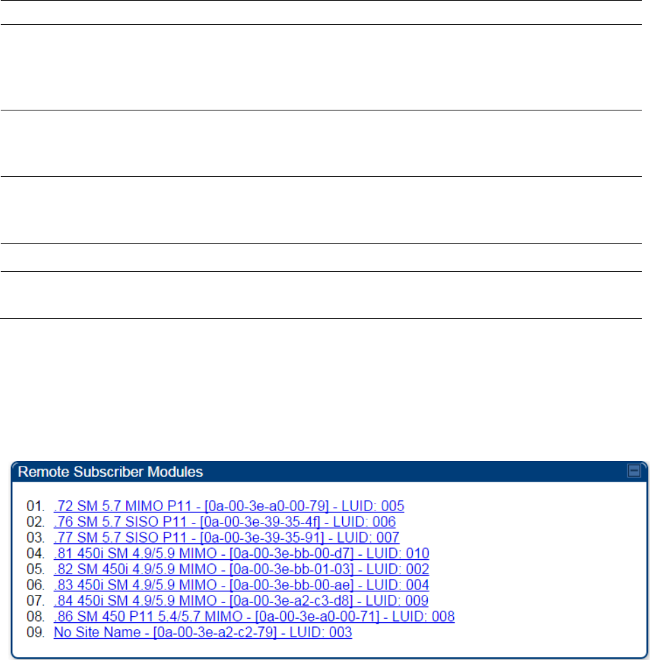
Chapter 9: Operation System information
Page 9-20
the
Sustained Data Rate (Downlink)
.
Max Burst Rate The data rate at which a SM/BHS is allowed to burst (until burst
allocation limit is reached) before being recharged at the
Sustained Data
Rate (Uplink and Downlink individually)
with credits to transit more.
When set to 0 (default), the burst rate is unlimited.
Low Priority CIR This field indicates the minimum rate at which low priority traffic is sent
over the uplink and downlink (unless CIR is oversubscribed or RF link
quality is degraded).
High CIR This field indicates the minimum rate at which high priority traffic is sent
over the uplink and downlink (unless CIR is oversubscribed or RF link
quality is degraded).
High Priority Queue Not applicable for PMP/PTP 450 platform products.
Broadcast/Multicast
Allocation
This field displays the data rate at which Broadcast and Multicast traffic
is sent via the radio link.
Viewing Remote Subscribers
This page allows to view the web pages of registered SMs or BHS over the RF link. To view the
pages for a selected SM/BHS, click its link. The
General Status
page of the SM opens.
Figure 143
Remote Subscribers page of AP
Interpreting messages in the Event Log
Each line in the Event Log of a module Home page begins with a time and date stamp. However,
some of these lines wrap as a combined result of window width, browser preferences and line
length. You may find this tab easiest to use if you expand the window till all lines are shown
beginning with time and date stamp.
Time and Date Stamp
The time and date stamp reflect one of the following:
• GPS time and date directly or indirectly received from the CMM4.
Chapter 9: Operation System information
Page 9-21
• NTP time and date from a NTP server (CMM4 may serve as an NTP server)
• The running time and date that you have set in the Time & Date web page.
Note
In the Time & Date web page, if you have left any time field or date field unset and
clicked the
Set Time and Date
button, then the time and date default to
00:00:00 UT
: 01/01/00.
A reboot causes the preset time to pause or, in some cases, to run in reverse.
Additionally, a power cycle resets the running time and date to the default 00:00:00
UT : 01/01/00. Thus, whenever either a reboot or a power cycle has occurred,
must reset the time and date in the Time & Date web page of any module that is not
set to receive sync.
Event Log Data Collection
The collection of event data continues through reboots and power cycles. When the buffer
allowance for event log data is reached, the system adds new data into the log and discards an
identical amount of the oldest data.
Each line that contains the expression WatchDog flags an event that was both:
• considered by the system software to have been an exception
• recorded in the preceding line.
Conversely, a Fatal Error () message flags an event that is recorded in the next line. Some
exceptions and fatal errors may be significant and require either operator action or technical
support.
Figure 144
Event log data

Chapter 9: Operation System information
Page 9-22
Messages that Flag Abnormal Events
The messages listed below flag abnormal events and, case by case, may signal the need for
corrective action or technical support.
Table 178
Event Log messages for abnormal events
Event Message
Meaning
Expected LUID = 6
Actual LUID = 7
Something is interfering with the control messaging of the module. Also
ensure that you are using shielded cables to minimize interference.
Consider trying different frequency options to eliminate or reduce
interference.
FatalError() The event recorded on the line immediately beneath this message
triggered the Fatal Error ().
Loss of GPS Sync
Pulse Module has lost GPS sync signal.
Machine Check
Exception
This is a symptom of a possible hardware failure. If this is a recurring
message, begin the RMA process for the module.
RcvFrmNum =
0x00066d
ExpFrmNum =
0x000799
Something is interfering with the control messaging of the module. Also
ensure that you are using shielded cables to minimize interference.
Consider trying different frequency options to eliminate or reduce
interference.
System Reset
Exception -- External
Hard Reset
The unit lost power or was power cycled.
System Reset
Exception -- External
Hard Reset
WatchDog
The event recorded on the preceding line triggered this WatchDog
message.
Messages that Flag Normal Events
The messages listed below record normal events and typically do not signal a need for any
corrective action or technical support.
Table 179
Event Log messages for normal events
Event Message
Meaning
Acquired GPS Sync
Pulse. Module has acquired GPS sync signal.
FPGA Features Type of encryption.
FPGA Version FPGA (JBC) version in the module.
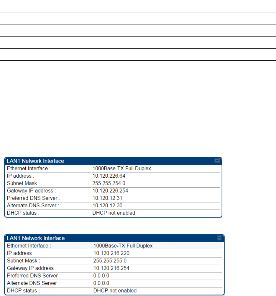
Chapter 9: Operation System information
Page 9-23
GPS Date/Time Set Module is now on GPS time.
Reboot from Webpage Module was rebooted from management interface.
Software Boot Version Boot version in the module.
Software Version The software release and authentication method for the unit.
System Log Cleared Event log was manually cleared.
Viewing the Network Interface
In any module, the LAN1 Network Interface section of this tab displays the defined Internet
Protocol scheme for the Ethernet interface to the module. In SM/BHS devices, this page also
provides an RF Public Network Interface section, which displays the Internet Protocol scheme
defined for network access through the master device (AP/BHM).
Figure 145
Network Interface tab of the AP
Figure 146
Network Interface tab of the SM
Chapter 9: Operation System information
Page 9-24
Viewing the Layer 2 Neighbors
In the Layer 2 Neighbors tab, a module reports any device from which it has received a message in
Link Layer Discovery Protocol within the previous two minutes. Given the frequency of LLDP
messaging, this means that the connected device will appear in this tab 30 seconds after it is
booted and remain until two minutes after its shutdown.
Figure 147
Layer 2 Neighbors page
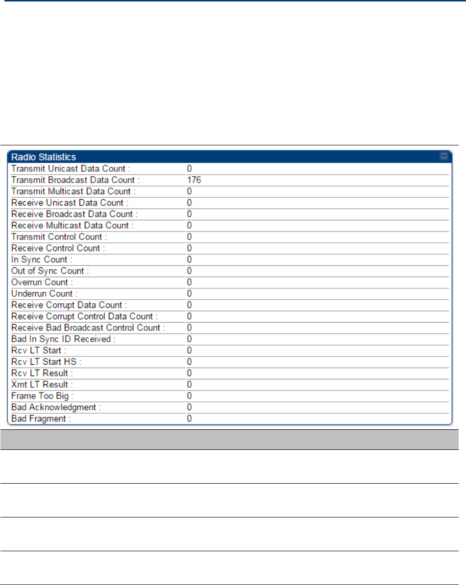
Chapter 9: Operation System statistics
Page 9-25
System statistics
This section describes how to use the system statistics pages to manage the performance of the
PMP/PTP 450 platform link.
Viewing the Scheduler statistics
The
Statistics > Scheduler
page is applicable for all modules (AP/SM/BHM/BHS) and the
parameters are displayed as shown below:
Table 180
Scheduler tab attributes
Attribute
Meaning
Transmit Unicast
Data Count The total amount of unicast packets transmitted from the radio
Transmit Broadcast
Data Count The total amount of broadcast packets transmitted from the radio
Transmit Multicast
Data Count The total amount of multicast packets transmitted by the radio
Receive Unicast Data
Count The total amount of unicast packets received by the radio

Chapter 9: Operation System statistics
Page 9-26
Receive Broadcast
Data Count The total amount of broadcast packets received by the radio
Transmit Control
Count
The amount of radio control type messages transmitted (registration
requests and grants, power adjust, etc.).
Receive Control
Count
The amount of radio control type messages received (registration
requests and grants, power adjust, etc.).
In Sync Count Number of times the radio has acquired sync. In the case of an AP
generating sync this is when generated sync has been locked, or if GPS
synchronization is used it is number of times GPS sync acquired. For the
SM, it is the number of times the SM successfully obtained sync with an
AP.
Out of Sync Count Number of times the radio lost same sync lock.
Overrun Count Number of times FPGA frame has overrun its TX Frame
Underrun Count Number of times FPGAs TX Frame aborted prematurely.
Receive Corrupt Data
Count Number of times a corrupt fragment has been received at the FPGA.
Receive Bad
Broadcast Control
Count
Number of times the radio has received an invalid control message via
broadcast (SM only).
Bad In Sync ID
Received Currently unused
Rcv LT Start Number of Link Test Start messages received. A remote radio has
requested that this radio start a link test to it.
Rcv LT Start HS Number of Link Test Start Handshake messages received. This radio
requested that a remote radio start a link test and the remote radio has
sent a handshake back acknowledging the start.
Rcv LT Result This radio received Link Test results from the remote radio under
test. When this radio initiates a link test, the remote radio will send its
results to this radio for display.
Xmt LT Result This radio transmitted its link test results to the remote radio under
test. When the remote radio initiates a link test, this radio must send its
results to the remote radio for display there.
Frame Too Big This statistics indicates the number of packets received and processed
by the radios which were greater than max packet size 1700 bytes.
Bad
Acknowledgment
This statistics indicates the number of packets received as bad
acknowledgment. It is for engineering use only.
Bad Fragment This statistic indicates number of fragments tagged internally as bad. It
is for engineering use only.
Chapter 9: Operation System statistics
Page 9-27
Viewing list of Registration Failures statistics
SM Registration Failures page of AP
The SM Registration Failures tab identifies SMs that have recently attempted and failed to register
to this AP. With its time stamps, these instances may suggest that a new or transient source of
interference exists.
Table 181
SM Registration Failures page attributes - AP
Attribute
Meaning
Status 17 Flag 0 No response was received from the AAA server and hence SM is trying
to send a session request again.
BHS Registration Failures page of BHM
Table 182
BHS Registration Failures page attributes - BHM
Attribute
Meaning
Status 17 Flag 0 No response was received from the AAA server and hence SM is trying
to send a session request again.
There is a list of flags from 0 to 20 as shown in Table 183 and the “Flags” can be ignored.
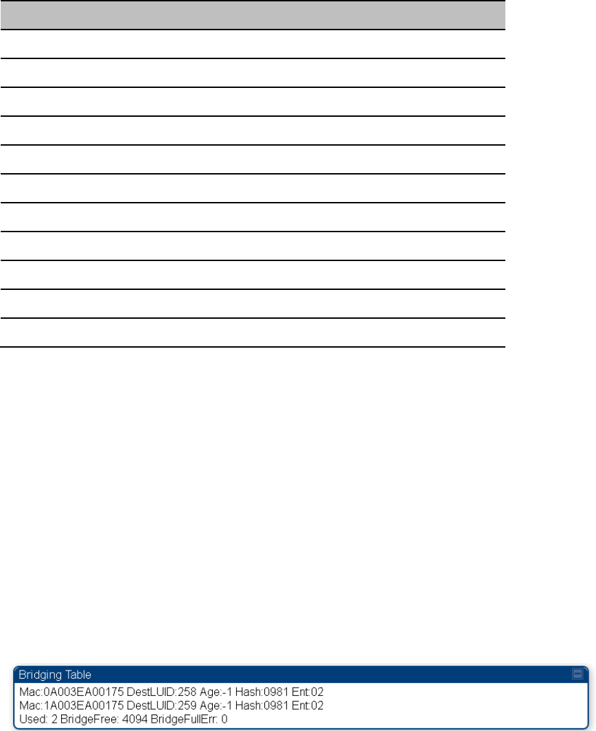
Chapter 9: Operation System statistics
Page 9-28
Table 183
Flags status
Flag
Meaning
Flag
Meaning
0 Normal 11 AP Lite Limit Reached
1 Out of Range 12 Only Ver 9.5+ Allowed
2 No Luids 13 Temporary Data VC for AAA
3 BH ReRange 14 AAA Authentication Failure
4 Auth Fail 15 Registration Grant Reject
5 Encrypt Fail 16 Blank
6 Power Adjust 17 AAA Session Retry
7 No VCs 18 AAA Reauth Failure
8 Reserve VC Fail 19 RegReq at zero power
9 Activate VC Fail 20 RegReq no time ref
10 Hi VC Setup Fail - -
Interpreting Bridging Table statistics
If NAT (network address translation) is not active on the SM/BHS, then the Bridging Table page
provides the MAC address of all devices that are attached to registered SMs/BHS (identified by
LUIDs). The bridging table allows data to be sent to the correct module as follows:
• For the AP/BHM, the uplink is from RF to Ethernet. Thus, when a packet arrives in the RF
interface to the AP/BHM, the AP/BHM reads the MAC address from the inbound packet and
creates a bridging table entry of the source MAC address on the other end of the RF interface.
• For the SM/BHS, the uplink is from Ethernet to RF. Thus, when a packet arrives in the Ethernet
interface to one of these modules, the module reads the MAC address from the inbound packet
and creates a bridging table entry of the source MAC address on the other end of the Ethernet
interface.
Figure 148
Bridging Table page
The Bridging Table supports up to 4096 entries.
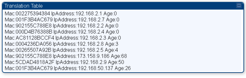
Chapter 9: Operation System statistics
Page 9-29
Interpreting Translation Table statistics
When Translation Bridging is enabled in the AP, each SM keeps a table mapping MAC addresses
of devices attached to the AP to IP addresses, as otherwise the mapping of end-user MAC
addresses to IP addresses is lost. (When Translation Bridging is enabled, an AP modifies all uplink
traffic originating from registered SMs such that the source MAC address of every packet is
changed to that of the SM which bridged the packet in the uplink direction.)
Figure 149
Translation Table page of SM
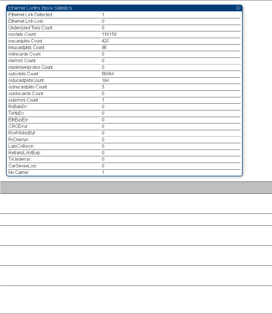
Chapter 9: Operation System statistics
Page 9-30
Interpreting Ethernet statistics
The
Statistics > Ethernet
page reports TCP throughput and error information for the Ethernet
connection of the module. This page is applicable for all modules (AP/SM/BHM/BHS).
The
Ethernet
page displays the following fields.
Table 184
Ethernet tab attributes
Attribute
Meaning
Ethernet Link
Detected
1 indicates that an Ethernet link is established to the radio, 0 indicates
that no Ethernet link is established
Ethernet Link Lost This field indicates a count of how many times the Ethernet link was lost.
Undersized Toss
Count
This field indicates the number of packets that were too small to process
and hence discarded.
inoctets Count This field displays how many octets were received on the interface,
including those that deliver framing information.
inucastpkts Count This field displays how many inbound subnetwork-unicast packets were
delivered to a higher-layer protocol.
Innucastpkts Count This field displays how many inbound non-unicast (subnetwork-
broadcast or subnetwork-multicast) packets were delivered to a higher-
layer protocol.
Chapter 9: Operation System statistics
Page 9-31
indiscards Count This field displays how many inbound packets were discarded without
errors that would have prevented their delivery to a higher-layer
protocol. (Some of these packets may have been discarded to increase
buffer space.)
inerrors Count This field displays how many inbound packets contained errors that
prevented their delivery to a higher-layer protocol.
inunknownprotos
Count
This field displays how many inbound packets were discarded because
of an unknown or unsupported protocol.
outoctets Count This field displays how many octets were transmitted out of the
interface, including those that deliver framing information.
outucastpkts Count This field displays how many packets for which the higher-level
protocols requested transmission to a subnetwork-unicast address. The
number includes those that were discarded or not sent.
outnucastpkts Count This field displays how many packets for which the higher-level
protocols requested transmission to a non-unicast (subnetwork-
broadcast or subnetwork-multicast) address. The number includes those
that were discarded or not sent.
outdiscards Count This field displays how many outbound packets were discarded without
errors that would have prevented their transmission. (Some of these
packets may have been discarded to increase buffer space.)
outerrrors Count This field displays how many outbound packets contained errors that
prevented their transmission.
RxBabErr This field displays how many receiver babble errors occurred.
TxHbErr This field displays how many transmit heartbeat errors have occurred.
EthBusErr This field displays how many Ethernet bus errors occurred on the
Ethernet controller.
CRCError This field displays how many CRC errors occurred on the Ethernet
controller.
RcvFifoNoBuf This field displays the number of times no FIFO buffer space was able to
be allocated
RxOverrun This field displays how many receiver overrun errors occurred on the
Ethernet controller.
Late Collision
This field displays how many late collisions occurred on the Ethernet
controller. A normal collision occurs during the first 512 bits of the frame
transmission. A collision that occurs after the first 512 bits is considered
a late collision.
Caution
A late collision is a serious network problem because the frame

Chapter 9: Operation System statistics
Page 9-32
being transmitted is discarded. A late collision is most commonly
caused by a mismatch between duplex configurations at the ends
of a link segment.
RetransLimitExp This field displays how many times the retransmit limit has expired.
TxUnderrun This field displays how many transmission-underrun errors occurred on
the Ethernet controller.
CarSenseLost This field displays how many carrier sense lost errors occurred on the
Ethernet controller.
No Carrier This field displays how many no carrier errors occurred on the Ethernet
controller.
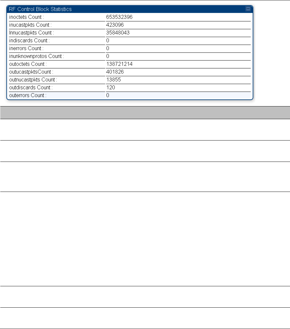
Chapter 9: Operation System statistics
Page 9-33
Interpreting RF Control Block statistics
The
Statistics > Radio
page is applicable for all module (AP/SM/BHM/BHS). The Radio page of the
Statistics page displays the following fields.
Table 185
Radio (Statistics) page attributes
Attribute
Meaning
inoctets Count This field displays how many octets were received on the interface,
including those that deliver framing information.
inucastpkts Count This field displays how many inbound subnetwork-unicast packets were
delivered to a higher-layer protocol.
Innucastpkts Count This field displays how many inbound non-unicast (subnetwork-
broadcast or subnetwork-multicast) packets were delivered to a higher-
layer protocol.
indiscards Count This field displays how many inbound packets were discarded without
errors that would have prevented their delivery to a higher-layer
protocol. This stat is pegged whenever corrupt data is received by
software or whenever the RF Software Bridge queue is full.
Corrupt data is a very unusual event because all packets are CRC
checked by hardware before being passed into software.
The likely case for indiscards is if the RF bridge queue is full. If this is the
case the radio is most likely PPS limited due to excessive small packet
traffic or a problem at the Ethernet interface. If there is a problem at the
Ethernet interface there is likely to be discards at the Ethernet as well.
inerrors Count This field displays how many inbound packets contained errors that
prevented their delivery to a higher-layer protocol.
inunknownprotos
Count
This field displays how many inbound packets were discarded because
of an unknown or unsupported protocol.
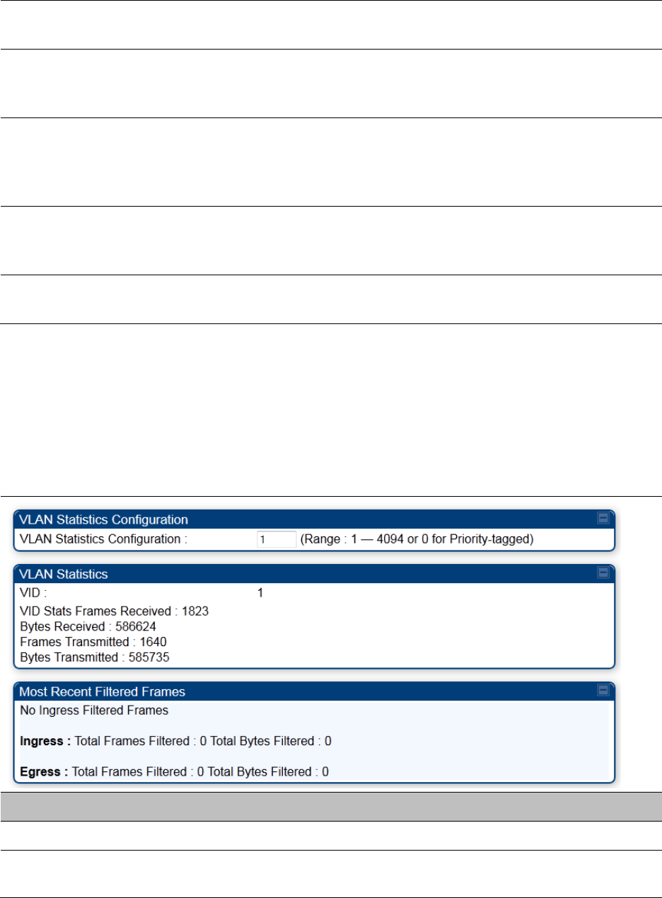
Chapter 9: Operation System statistics
Page 9-34
outoctets Count This field displays how many octets were transmitted out of the
interface, including those that deliver framing information.
outucastpkts Count This field displays how many packets for which the higher-level
protocols requested transmission to a subnetwork-unicast address. The
number includes those that were discarded or not sent.
outnucastpkts Count This field displays how many packets for which the higher-level
protocols requested transmission to a non-unicast (subnetwork-
broadcast or subnetwork-multicast) address. The number includes those
that were discarded or not sent.
outdiscards Count This field displays how many outbound packets were discarded without
errors that would have prevented their transmission. (Some of these
packets may have been discarded to increase buffer space.)
outerrrors Count This field displays how many outbound packets contained errors that
prevented their transmission.
Interpreting VLAN statistics
The
Statistics > VLAN
page provides a list of the most recent packets that were filtered because of
VLAN membership violations. It is applicable for all modules (AP/SM/BHM/BHS).
Table 186
VLAN page attributes
Attribute
Meaning
Unknown This must not occur. Contact Technical Support.
Only Tagged The packet was filtered because the configuration is set to accept only
packets that have an 802.1Q header and this packet did not.

Chapter 9: Operation System statistics
Page 9-35
Ingress When the packet entered through the wired Ethernet interface,
the packet was filtered because it indicated an incorrect VLAN
membership.
Local Ingress When the packet was received from the local TCP/IP stack, the packet
was filtered because it indicated an incorrect VLAN membership.
This must not occur. Contact Technical Support.
Egress When the packet attempted to leave through the wired Ethernet
interface, the packet was filtered because it indicated an incorrect VLAN
membership.
Local Egress When the packet attempted to reach the local TCP/IP stack, the packet
was filtered because it indicated an incorrect VLAN membership.
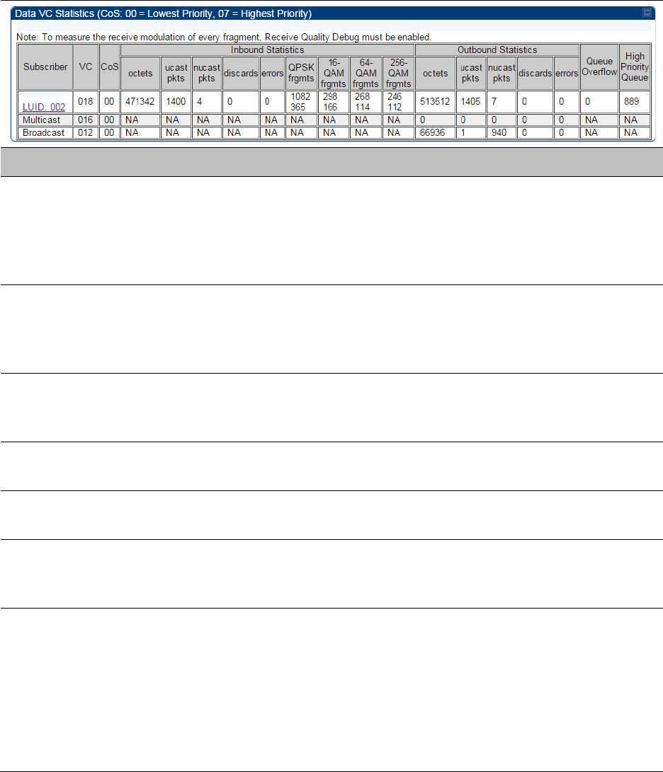
Chapter 9: Operation System statistics
Page 9-36
Interpreting Data VC statistics
The
Statistics
>
Data VC
page displays information about Virtual Channel (VC) used in data
communications. This page is applicable for all modules (AP/SM/BHM/BHS).
The
Data VC
tab displays the fields as explained in Table 187.
Table 187
Data VC page attributes
Attribute
Meaning
Subscriber This field displays the LUID (logical unit ID), MAC address and Site Name
of the SM/BHS. As each SM or BHS registers to the AP/BHM, the system
assigns an LUID of 2 or a higher unique number to the SM/BHS. If a
SM/BHS loses registration with the AP/BHM and then regains
registration, the SM/BHS retains the same LUID.
VC This field displays the virtual channel number. Low priority channels
start at VC18 and count up. High priority channels start at VC255 and
count down. If one VC is displayed, the high-priority channel is disabled.
If two are displayed, the high-priority channel is enabled.
CoS This field displays the Class of Service for the virtual channel. The low
priority channel is a CoS of 00 and the high priority channel is a CoS of
01. CoS of 02 through 07 are not currently used.
Inbound Statistics,
octets
This field displays how many octets were received on the interface,
including those that deliver framing information.
Inbound Statistics,
ucastpkts
This field displays how many inbound subnetwork-unicast packets were
delivered to a higher-layer protocol.
Inbound Statistics,
nucastpkts
This field displays how many inbound non-unicast (subnetwork-
broadcast or subnetwork-multicast) packets were delivered to a higher-
layer protocol.
Inbound Statistics,
discards
This field displays how many inbound packets were discarded without
errors that would have prevented their delivery to a higher-layer
protocol. Inbound discard statistics are incremented similar to the
indiscards stat on the RF control block stats page. The sum of all data VC
indiscards must be close to the RF control block in discards. If indiscards
are evenly distributed across SMs, then the radio is PPS limited due to
either excessive small packet transmissions, or a problem at the Ethernet
link. If indiscards are contained to one or a few SMs, then there is likely a

Chapter 9: Operation System statistics
Page 9-37
problem at or underneath the SM which is incrementing the count.
Inbound Statistics,
errors
This field displays how many inbound packets contained errors that
prevented their delivery to a higher-layer protocol.
Inbound Statistics,
QPSK frgmts
This field displays how many inbound fragments were received via the
QPSK modulation scheme.
Inbound Statistics,
16-QAM frgmts
This field displays how many inbound fragments were received via the
16-QAM modulation scheme.
Inbound Statistics,
64-QAM frgmts
This field displays how many inbound fragments were received via the
64-QAM modulation scheme.
Inbound Statistics,
256-QAM frgmts
This field displays how many inbound fragments were received via the
256-QAM modulation scheme.
Outbound Statistics,
octets
This field displays how many octets were transmitted out of the
interface, including those that deliver framing information.
Outbound Statistics,
ucastpkts
This field displays how many packets for which the higher-level
protocols requested transmission to a subnetwork-unicast address. The
number includes those that were discarded or not sent.
Outbound Statistics,
nucastpkts
This field displays how many packets for which the higher-level
protocols requested transmission to a non-unicast (subnetwork-
broadcast or subnetwork-multicast) address. The number includes those
that were discarded or not sent.
Outbound Statistics,
discards
This field displays how many outbound packets were discarded without
errors that would have prevented their transmission. Outbound discard
statistics are incremented if a VC is not active when a packet is ready to
send. This is a rare condition.
Outbound Statistics,
errors
This field displays how many outbound packets contained errors that
prevented their transmission.
Queue Overflow This is a count of packets that were discarded because the queue for the
VC was already full. If Queue Overflows are being seen across most or
all SMs, then there is either an interferer local to the AP or the APs RF
link is at capacity. If Queue Overflows are being seen at one or only a
few SMs, then it is likely that there is a problem with those specific links
whether it is insufficient signal strength, interferer, or a problem with the
actual SM hardware.
High Priority Queue This is a count of packets that were received on high priority queue.
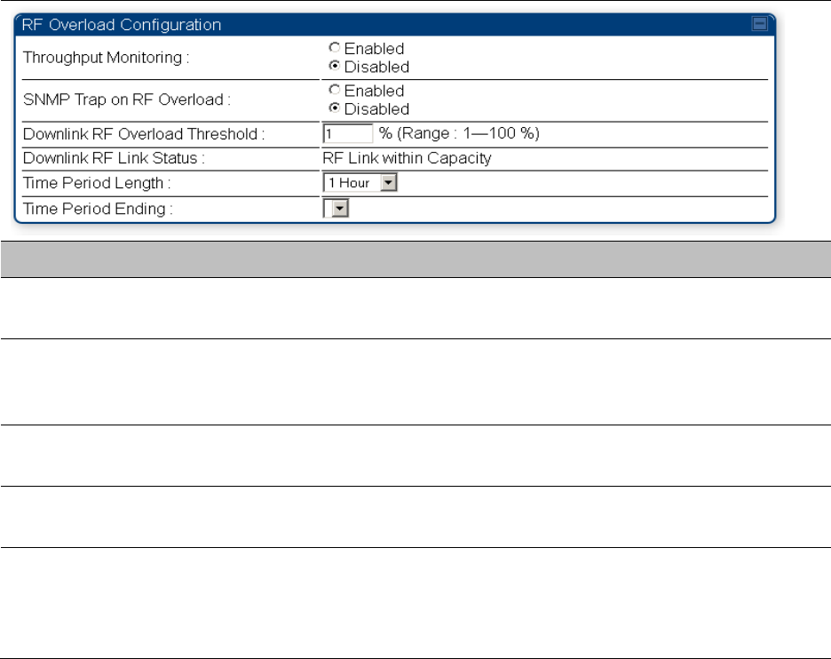
Chapter 9: Operation System statistics
Page 9-38
Interpreting Throughput statistics
The PMP/PTP 450 platform has a
Statistics
>
Throughput
page which shows historical information
about sector or backhaul throughput and packet discards. This page is applicable for AP and BHM
modules. This information can be useful to identify an overloaded sector or heavy bandwidth
users. This page also shows the user throughput in terms of data rate (kbps) and packet rate
(packets per second, or PPS), as well as the average packet size during the sample period.
Operators may set the AP/BHM to send an SNMP trap when it detects an RF overload condition
based on a configurable threshold.
The following configuration parameters are available on the Throughput tab GUI pane and a radio
reboot is not required when configuring these parameters:
Table 188
RF overload Configuration attributes – AP/BHM
Attribute
Meaning
Throughput
Monitoring
This enables or disables the monitoring of sector throughput and packet
discards. This parameter is disabled by default.
SNMP Trap on RF
Overload
This enables or disables the sending of an SNMP trap when an AP/BHM
overload condition is reached (based on Downlink RF Overload
Threshold).
Downlink RF
Overload Threshold
This parameter determines the overload threshold in percent of packets
discarded that triggers the generation of an SNMP trap.
Downlink RF Link
Status
This field displays the status of the capacity of the RF link.
Time Period Length
Time Period Ending
These two configuration parameters determine what set of collection
samples to show on the GUI display. The Time Period Length can be set
from one to three hours. Time Period Ending allows the operator to set
the end time for the set of collection samples to display.
Below the configuration settings are three tables that display the statistics that are collected.
Chapter 9: Operation System statistics
Page 9-39
Board Performance statistics
This table contains a row that corresponds to each 1 minute statistics collection interval. Each row
contains the following data aggregated for the entire AP/BHM:
•
Ethernet Throughput
- Statistics collected at the Ethernet port:
o
kbps in
– average throughput over the collection interval in Kbps into the AP/BHM on the
Ethernet Interface
o
kbps out
– average throughput over the collection interval in Kbps out of the AP/BHM on
the Ethernet Interface
o
PPS in
– average packets per second over the collection interval into the AP/BHM on the
Ethernet Interface
o
PPS out
– average packets per second over the collection interval out of the AP/BHM on the
Ethernet Interface
•
RF Throughput -
Statistics collected at the RF Interface:
o
kbps in
– average throughput over the collection interval in Kbps into the AP/BHM on the
RF Interface
o
kbps out
– average throughput over the collection interval in Kbps out of the AP/BHM on
the RF Interface
o
PPS in
– average packets per second over the collection interval into the AP/BHM on the RF
Interface
o
PPS out
– average packets per second over the collection interval out of the AP/BHM on the
RF Interface
•
Aggregate Through Board
– Sum of bidirectional data transferred through (not originating or
terminating at) the AP/BHM:
o
kbps
– average bidirectional throughput over the collection interval in Kbps
o
PPS
– average bidirectional packets per second over the collection interval
o
Ave Pkt Size
– Average Packet size over the collection interval of bidirectional data
transferred
Board Throughput statistics
This table contains a row that corresponds to each one minute statistics collection interval. This
table may be used to determine if there are problems with any of the interfaces. For example, if the
Ethernet in packets is much higher than the RF out packets it could indicate a denial of service
(DoS) attack on the AP/BHM. Each row contains the following data aggregated for the entire
AP/BHM:
•
Ethernet Statistics
- Statistics collected at the Ethernet port:
o
inOctets
– Number of octets (bytes) received by the AP/BHM at the Ethernet Interface over
the collection interval
o
outOctets
– Number of octets (bytes) sent by the AP/BHM at the Ethernet Interface over the
collection interval
o
inPkts
– Number of packets received by the AP/BHM at the Ethernet Interface over the
collection interval
o
outPkts
– Number of packets sent by the AP/BHM at the Ethernet Interface over the
collection interval
Chapter 9: Operation System statistics
Page 9-40
o
Discards (in/out)
– Number of packets that had to be discarded by the AP/BHM at the
respective Ethernet Interface Queue
•
RF Statistics
- Statistics collected at the RF Interface:
o
inOctets
– Number of octets (bytes) received by the AP/BHM at the RF Interface over the
collection interval
o
outOctets
– Number of octets (bytes) sent by the AP/BHM at the RF Interface over the
collection interval
o
inPkts
– Number of packets received by the AP/BHM at the RF Interface over the collection
interval
o
outPkts
– Number of packets sent by the AP/BHM at the RF Interface over the collection
interval
o
Discards (in/out)
– Number of packets that had to be discarded by the AP/BHM at the
respective RF Interface Queue during the collection interval
o
Discards % (in/out)
– Percent of the total packets received / transmitted that had to be
discarded during the collection interval
LUID RF Throughput statistics
This table contains a row that corresponds to each active LUID served by the AP/BHM. Note that an
LUID may be assigned 1 or 2 VCs. If the LUID is assigned 2 VCs, then the data in the table is the
sum of the activity for both VCs. This table may be used to determine which LUIDs are
experiencing overload so that corrective action can be taken (i.e. fixing a poor RF link or moving a
heavily loaded link to a less congested AP/BHM). Each row contains counters and statistics related
to the RF Interface that are updated once per minute:
•
Inbound Statistics
- Statistics collected at the RF Interface for the Uplink:
o
octets
– Number of octets (bytes) received by the AP/BHM at the RF Interface for this LUID
over the collection interval
o
pkts
– Number of packets received by the AP/BHM at the RF Interface for this LUID over the
collection interval
o
Ave Pkt Size
– Average size of the packets received by the AP/BHM at the RF Interface for
this LUID over the collection interval
o
discards
– Number of packets received by the AP/BHM at the RF Interface for this LUID over
the collection interval that had to be discarded because the RF In Queue was full
o
discards %
– Percent of the total packets received by the AP/BHM at the RF Interface for this
LUID over the collection interval that had to be discarded because the RF In Queue was full
•
Outbound Statistics
- Statistics collected at the RF Interface for the Downlink:
o
octets
– Number of octets (bytes) transmitted by the AP/BHM at the RF Interface for this
LUID over the collection interval
o
pkts
– Number of packets transmitted by the AP/BHM at the RF Interface for this LUID over
the collection interval
o
Ave Pkt Size
– Average size of the packets transmitted by the AP/BHM at the RF Interface
for this LUID over the collection interval
o
discards
– Number of packets to be transmitted by the AP/BHM at the RF Interface for this
LUID over the collection interval that had to be discarded because the RF Out Queue was
full
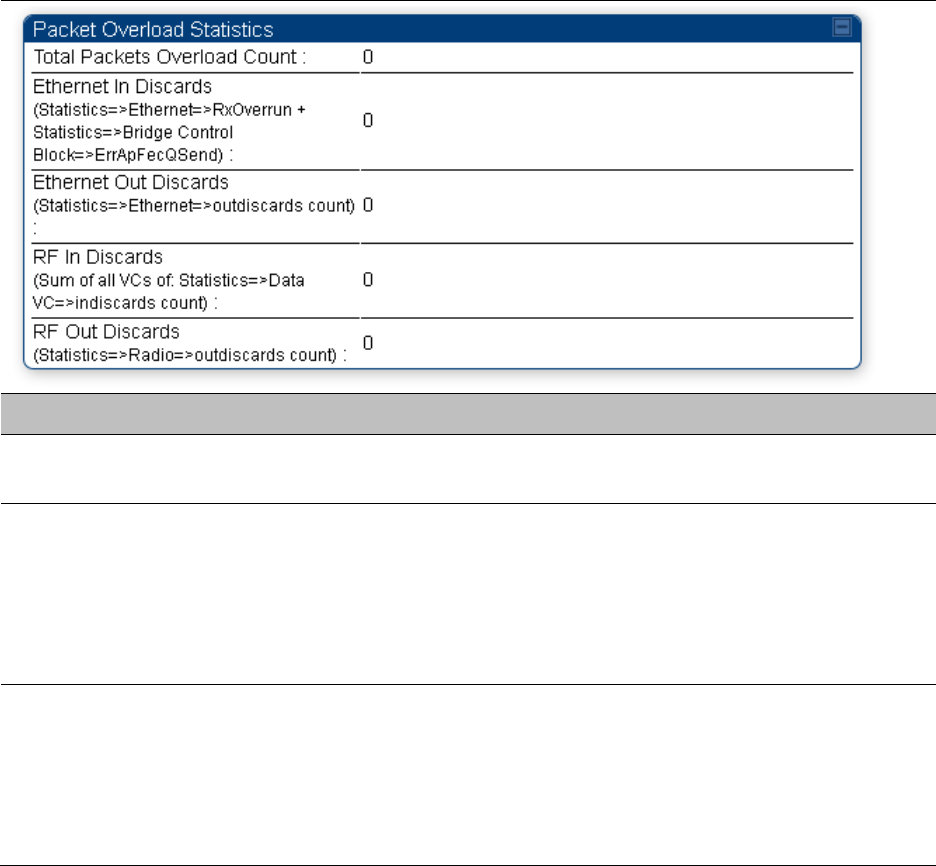
Chapter 9: Operation System statistics
Page 9-41
o
discards %
– Percent of the total packets to be transmitted by the AP/BHM at the RF
Interface for this LUID over the collection interval that had to be discarded because the RF
Out Queue was full.
Interpreting Overload statistics
The Statistics > Overload page displays statistics on packet overload and resultant packet discards.
Unlike the other fields, the Total Packets Overload Count is expressed in only this page. It is not a
count of how many packets have been lost, but rather of how many discard events (packet loss
bursts) have been detected due to overload condition.
This statistics page is applicable for all modules (AP/SM/BHM/BHS) and explained in Table 189.
Table 189
Overload page attributes – AP/SM/BHM/BHS
Attribute
Meaning
Total Packets
Overload Count
This field represents the sum of all RF and Ethernet in/out discards.
Ethernet In Discards This field represents the number of packets tossed due to the Ethernet
queue being full. If a climb in this stat accompanies a climb in RF Out
Discards stat, then most likely the board is at RF capacity either due to
traffic exceeding the RF pipe, or interference temporarily limiting the RF
throughput. If this stat climbs without the RF Out Discards stat climbing,
then the radio is most likely PPS limited.
Ethernet Out
Discards
This field represents the number of packets tossed due to an Ethernet
out overload. This stat must not climb in normal operation because the
Ethernet link is much higher capacity than the RF link. If this stat is
incrementing, then either the Ethernet link is established at a low speed
(i.e. 10Mbps – half duplex), or there is a problem with cabling/Ethernet
hardware.
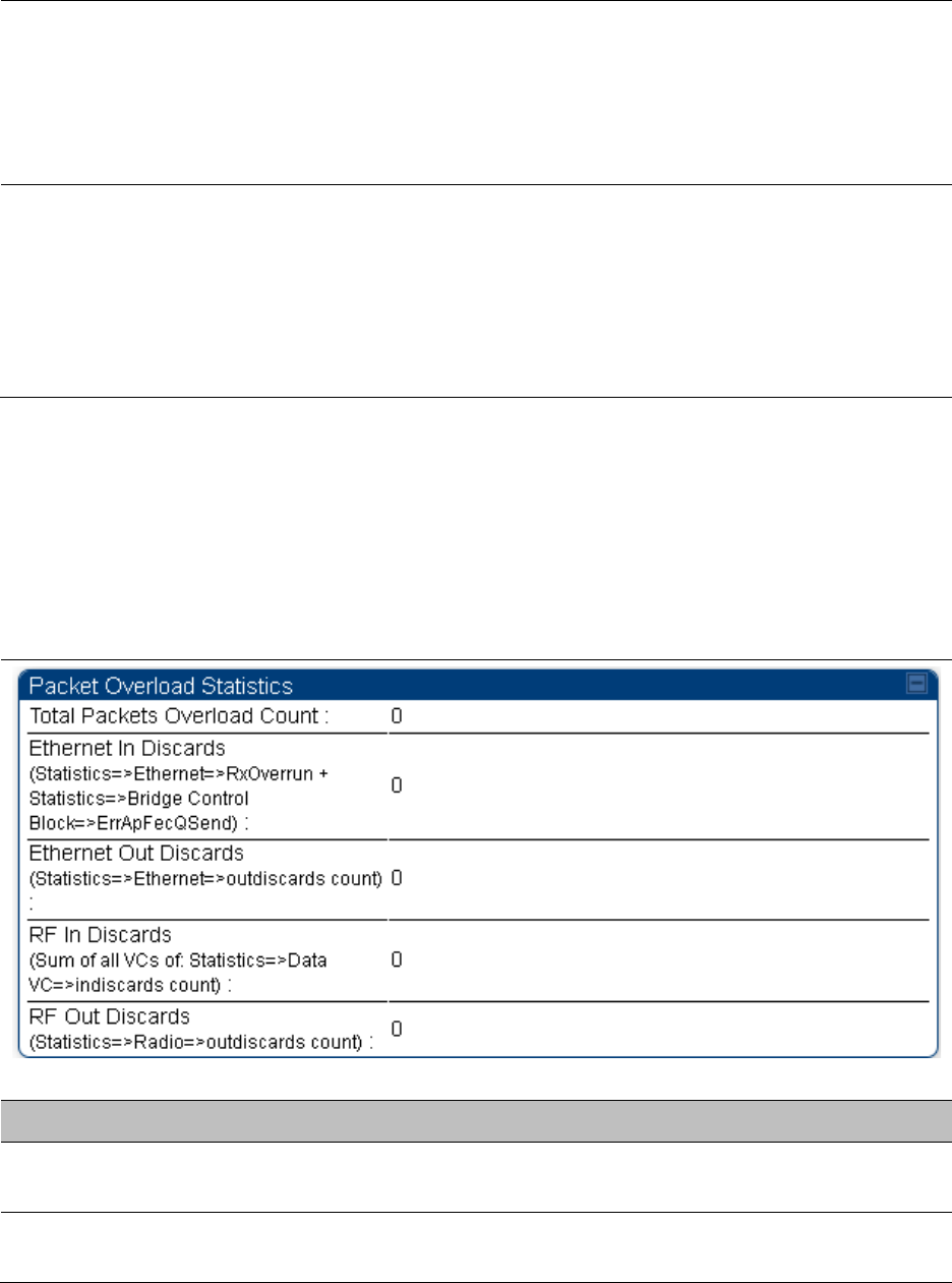
Chapter 9: Operation System statistics
Page 9-42
RF In Discards This field indicates the number of packets tossed due to no resources
available within the radio to process them. This stat also must not be
increasing because the system is designed to shed packets on the RF
Out interface. If this stat is incrementing the board, it is most likely
congested due to high PPS rate in combination with an Ethernet Out
problem, which limits packet flow off the device.
RF Out Discards This field indicates the number of packets tossed due to RF link at
capacity. This stat will increase whenever the RF link is at capacity. When
the internal FPGA RF input queue overflows, this stat is incremented. If
this stat is seen to be incrementing at the AP, then the sector is
congested. If seen at the SM, the number of Contention Slots must be
looked at to ensure that enough Contention Slots are allocated to allow
for bandwidth requests to be seen at the AP.
Interpreting DHCP Relay statistics
The
Statistics > DHCP Relay
page displays requests and replies received, relayed and discarded
when the AP is configured as a DHCP relay. Typically, in a working DHCP relay configuration a
one-to-one ratio is established between requests and replies that are received and relayed. This
statistics page is only applicable for PMP (AP and SM modules) and it is explained in Table 190.
Table 190
DHCP Relay page attributes – AP/SM
Attribute
Meaning
Requests Received This field represents the number of DHCP relay requests received by the
AP.
Requests Relayed This field represents the number of DHCP relay requests relayed by the
AP.
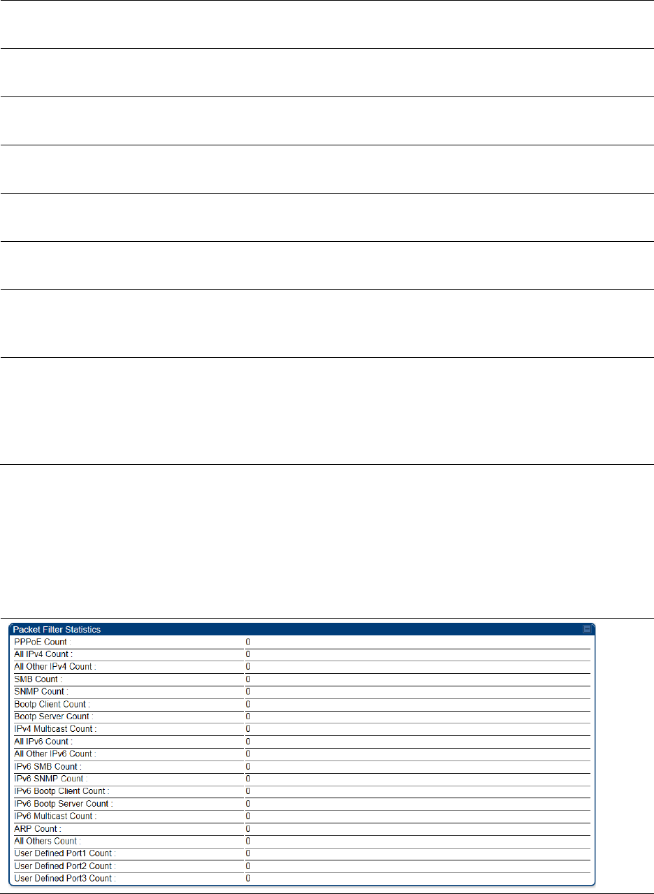
Chapter 9: Operation System statistics
Page 9-43
Requests Discarded This field represents the number of DHCP relay requests discarded by
the AP due to errors in the request.
Replies Received This field represents the number of DHCP relay replies received by the
AP.
Replies Relayed This field represents the number of DHCP relay replies relayed by the
AP.
Replies Discarded This field represents the number of DHCP relay replies discarded by the
AP due to errors in the reply.
Untrusted Message
Discards
This field indicates messages that were discarded because the message
already contained Option 82 information with no Relay Agent specified.
Max Hop Exceeded
Discards
This field indicates messages that have been relayed too many times,
exceeding the max hop count (16).
Invalid Relay Agent
Address Discards
This field indicates messages that have been discarded because the
message relay agent address is already in place (relay agent address
does not equal address of the AP).
Relay Info Exceeding
Max Message Size
(DHCP message
relayed without
Option 82)
This field indicates DHCP messages too large to fit Option 82 data. These
messages are sent on without Option 82 information.
Interpreting Filter statistics
The
Statistics > Filter
page displays statistics on packets that have been filtered (dropped) due to
the filters set on the
Protocol Filtering
page. The filter page of SM is explained in Table 191.
Table 191
Filter page attributes - SM

Chapter 9: Operation System statistics
Page 9-44
Attribute
Meaning
PPPoE Count Number of PPoE packets filtered.
All IPv4 Count Number of IPv4 packets filtered.
All Other IPv4 Count Any IPv4 message that was not SMB, SNMP, Bootp, Multicast or
one of the user defined filters, that was filtered out.
SMB Count Number of IPv4 Server Message Block (file sharing) packets filtered.
SNMP Count Number of IPv4 SNMP packets filtered.
Bootp Client Count Total number of IPv4 DHCP requests filtered.
Bootp Server Count Total number of IPv4 DHCP replies filtered.
IPv4 Multicast Count Number of IPv4 Multicast messages filtered.
All IPv6 Count Number of IPv6 messages filtered.
All Other IPv6 Count Any IPv6 message that was not SMB, SNMP, Bootp, Multicast or
one of the user defined filters, that was filtered out.
IPv6 SMB Count Number of IPv6 Server Message Block (file sharing) packets filtered
IPv6 SNMP Count Number of IPv6 SNMP messages filtered
IPv6 Bootp Client Count Total number of IPv6 DHCP replies filtered
IPv6 Bootp Server Count Total number of IPv6 DHCP replies filtered
IPv6 Multicast Count Number of IPv6 Multicast messages filtered
ARP Count Total number of ARP packets filtered.
All other Count The count of any messages that did not fit above that were filtered
out
User Defined Port1 Count Number of packets defined by the user port1 that were filtered.
User Defined Port2 Count Number of packets defined by the user port2 that were filtered.
User Defined Port3 Count Number of packets defined by the user port3 that were filtered.
Viewing ARP statistics
The
Statistics > ARP
page in a SM module correlated the IP address of the Ethernet-connected
device to its MAC address and provides data about the connection.
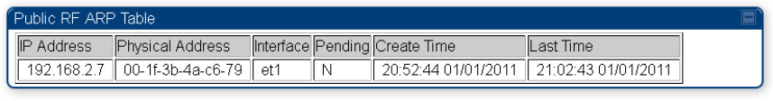
Chapter 9: Operation System statistics
Page 9-45
Figure 150
ARP page of the SM
Viewing NAT statistics
When NAT is enabled on a SM, statistics are kept on the Public and Private (WAN and LAN) sides
of the NAT and displayed on the
Statistics > NAT Stats
page. The NAT page of SM is explained in
Table 192.
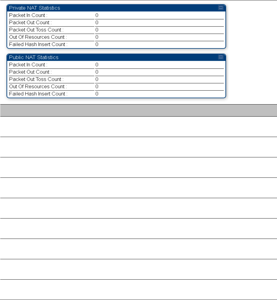
Chapter 9: Operation System statistics
Page 9-46
Table 192
NAT page attributes - SM
Attribute
Meaning
Private NAT Statistics,
Packet In Count
This field represents the number of packets received on the SM’s
LAN/Ethernet interface
Private NAT Statistics,
Packet Out Count
This field represents the number of packets sent from the SM’s
LAN/Ethernet interface
Private NAT Statistics,
Packet Out Toss Count
This field represents the number of packets that we not sent from the
SM’s LAN/Ethernet interface due to addressing issues.
Private NAT Statistics,
Out of Resources Count
This field represents the number of times the NAT table for the SM’s
LAN/Ethernet interfaces has been filled.
Private NAT Statistics,
Failed Hash Insert Count
This field represents the number of times that the device failed to
insert an address binding into the NAT hash table.
Public NAT Statistics,
Packet In Count
This field represents the number of packets received on the SM’s
WAN/wireless interface
Public NAT Statistics,
Packet Out Count
This field represents the number of packets sent from the SM’s
WAN/wireless interface
Public NAT Statistics,
Out of Resources Count
This field represents the number of packets that we not sent from the
SM’s WAN/wireless interface due to addressing issues.
Public NAT Statistics,
Failed Hash Insert Count
This field represents the number of times the NAT table for the SM’s
WAN/wireless interfaces has been filled.
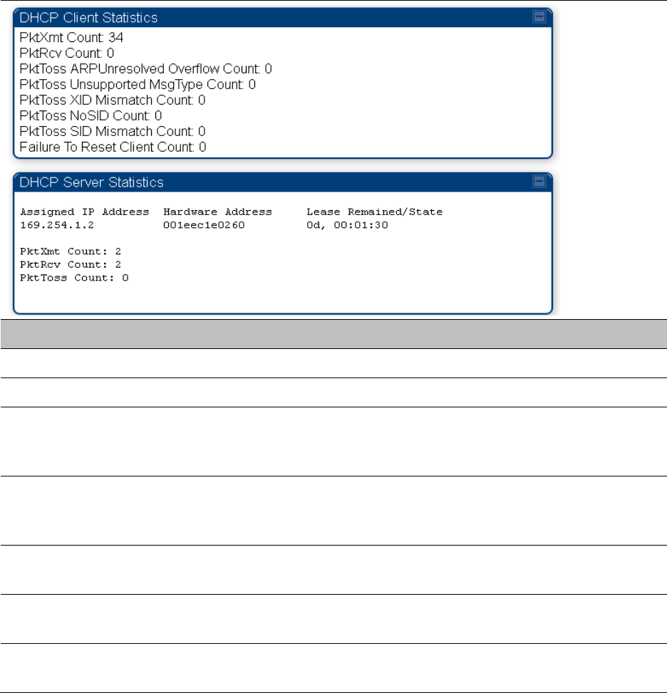
Chapter 9: Operation System statistics
Page 9-47
Viewing NAT DHCP Statistics
The Statistics > NAT DHCP page displays NAT enabled DHCP client statistics. This is statistics page
is applicable for SM only.
When NAT is enabled on a SM with DHCP client (
DHCP
selected as the
Connection Type
of the
WAN interface) and/or DHCP Server, statistics are kept for packets transmitted, received and
tossed, as well as a table of lease information for the DHCP server (Assigned IP Address, Hardware
Address and Lease Remained/State).
Table 193
NAT DHCP Statistics page attributes - SM
Attribute
Meaning
PktXmt Count Represents the number of DHCP packets transmitted from the client
PktRcv Count This field represents the number of DHCP packets received by the client
PktToss
ARPUnresolved
Overflow Count
This field represents the number of packets tossed due to failed attempts
to resolve an IP address into a physical MAC address
PktToss
Unsupported
MsgType Count
This field represents the number of packets tossed due to the receipt of
an unsupported message type (cannot be interpreted by DHCP client)
PktToss XID
Mismatch Count
The field represents the number of packets that were tossed due to a
transaction ID mismatch
PktToss NoSID
Count
This field represents the number of packets that were tossed due to lack
of a DHCP session ID
PktToss SID
Mismatch Count
Represents the number of packets tossed due to a session ID mismatch
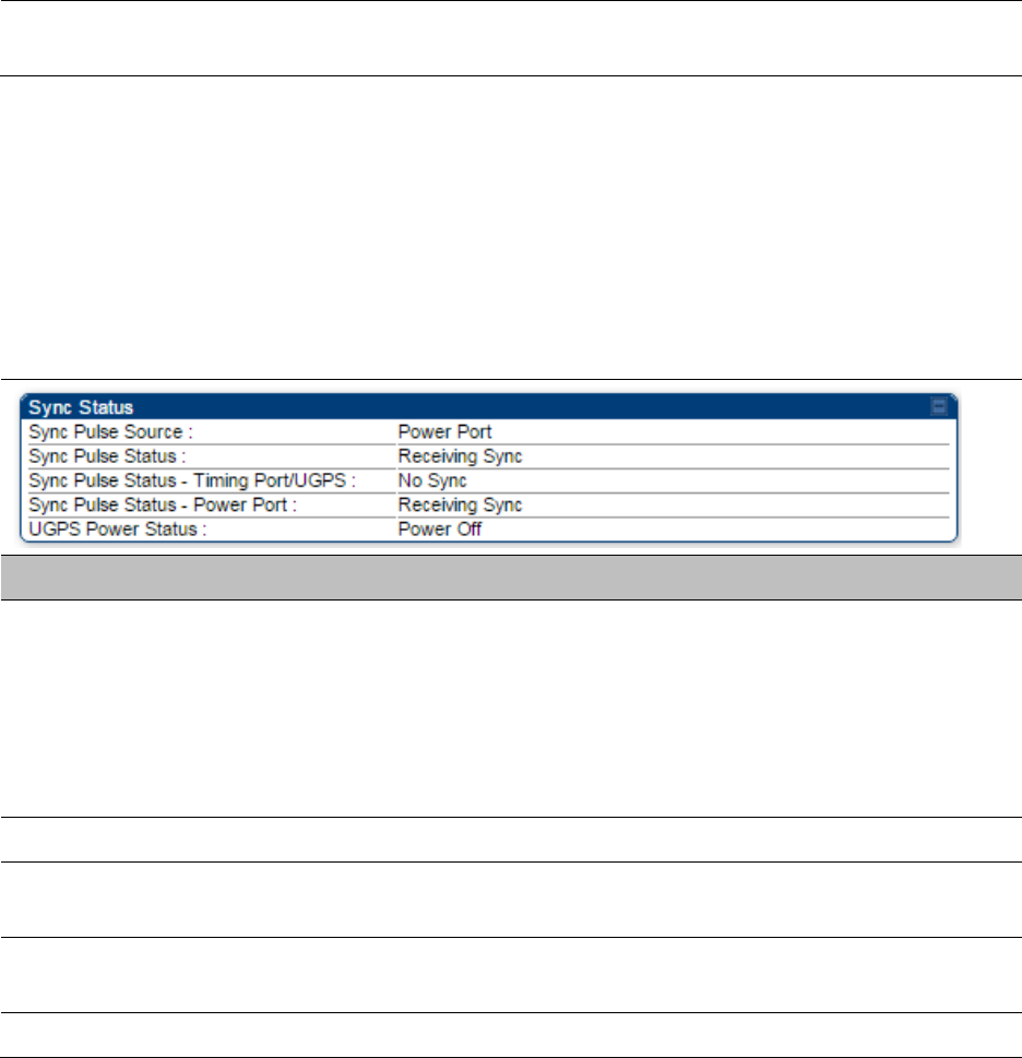
Chapter 9: Operation System statistics
Page 9-48
Failure to Reset
Client Count
This field represents the number of times the DHCP client was unable to
be reset (resulting in no IP address being served).
Interpreting Sync Status statistics
The
Statistics > Sync Status
page of AP is only displayed when the Sync Input is set to AutoSync
or AutoSync+Free Run.
The Sync Status page is explained in Table 194.
Table 194
Sync Status page attributes - AP
Attribute
Meaning
Sync Pulse Source This field indicates the status of the synchronization source:
•
Searching
indicates that the unit is searching for a GPS fix
•
Timing Port/UGPS
indicates that the module is receiving sync via the
timing AUX/SYNC timing port
•
Power Port
indicates that the module is receiving sync via the power
port (Ethernet port).
Sync Pulse Status This field indicates synchronization source pulse status.
Sync Pulse Status –
Timing Port/UGPS
This field indicates synchronization pulse status over Timing Port/UGPS
port.
Sync Pulse Status -
Power Port
This field indicates synchronization pulse status over power port.
UGPS Power Status This field indicates UGPS power up status (on or off).
This information may be helpful in a decision of whether to climb a tower to diagnose a perceived
antenna problem.
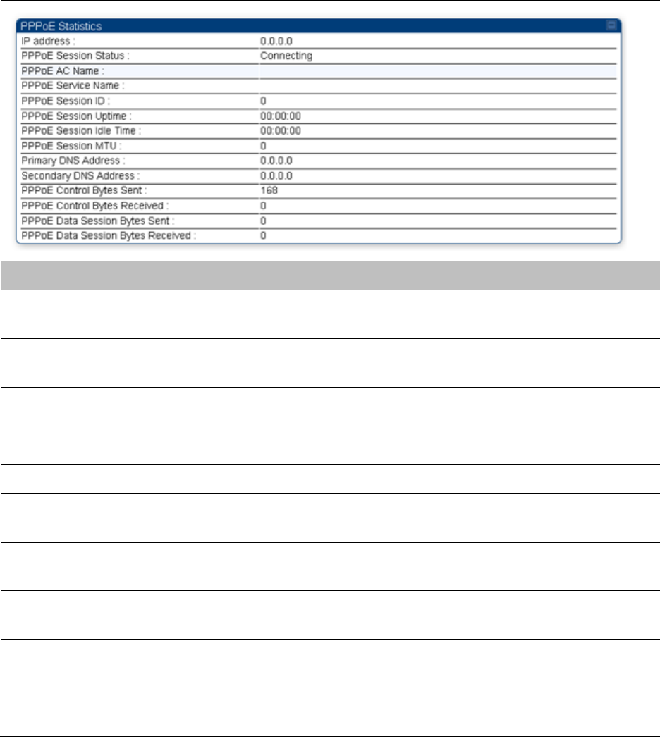
Chapter 9: Operation System statistics
Page 9-49
Interpreting PPPoE Statistics for Customer Activities
The page can be access under
Statistics > PPPoE
of SM GUI.
When the PPPoE feature is enabled on the SM, PPPoE statistics provide data about activities of the
customer.
The PPPoE Statistics of SM is explained in Table 195.
Table 195
PPPoE Statistics page attributes - SM
Attribute
Meaning
IP address This field displays the IP address of the PPPoE session initiator (situated
below the SM)
PPPoE Session
Status
This field displays the operational status of the PPPoE Session
PPPoE AC Name This field displays access concentrator name used in the PPPoE session
PPPoE Service Name This field displays the PPPoE service name associated with the PPPoE
server in use
PPPoE Session ID This field displays the current PPPoE session ID
PPPoE Session
Uptime
This field displays the total session uptime for the PPPoE session
PPPoE Session Idle
Time
This field displays the total idle time for the PPPoE session
PPPoE Session MTU This field displays Maximum Transmission Unit configured for the
PPPoE session
Primary DNS
Address
This field displays the primary DNS server used by the PPPoE session
Secondary DNS
Address
This field displays the secondary DNS server used by the PPPoE session
Chapter 9: Operation System statistics
Page 9-50
PPPoE Control Bytes
Sent
Displays the total number of PPPoE session control bytes sent from SM
PPPoE Control Bytes
Received
This field displays the total number of PPPoE session control bytes
received by the SM
PPPoE Data Session
Bytes Sent
This field displays the total number of PPPoE data session (non-
control/non-session management user data) sent by the SM
PPPoE Data Session
Bytes Received
This field displays the total number of PPPoE data session (non-
control/non-session management user data)
Interpreting Bridge Control Block statistics
The
Statistics > Bridge Control Block
page displays statistics of Bridge FEC, Bridge ratio and Bridge
error. The page is applicable for all modules (AP/SM/BHM/BHS). The Bridge Control Block
Statistics page is explained in Table 196.
Table 196
Bridge Control Block page attributes – AP/SM/BHM/BHS

Chapter 9: Operation System statistics
Page 9-51
Attribute
Meaning
FEC bin This field indicates the number of broadcast packets received by the
bridge control block on the Ethernet interface
FEC bout This field indicates the number of broadcast packets sent by the bridge
control block on the Ethernet interface
FEC btoss This field indicates the number of broadcast packets tossed out by the
bridge control block on the Ethernet interface
FEC btosscap This field indicates the number of broadcast packets tossed out at the
Ethernet interface due to MIR cap being exceeded.
FEC uin This field indicates the number of unicast packets received by the bridge
control block on the Ethernet interface
FEC uout This field indicates the number of unicast packets sent by the bridge
control block on the Ethernet interface
FEC utoss This field indicates the number of unicast packets tossed by the bridge
control block on the Ethernet interface
FEC utosscap This field indicates the number of unicast packets tossed out at the
Ethernet interface due to MIR cap being exceeded.
RF bin This field indicates the number of broadcast packets received by the
bridge control block on the radio interface
RF bout This field indicates the number of broadcast packets sent by the bridge
control block on the radio interface
RF btoss This field indicates the number of broadcast packets tossed by the
bridge control block on the radio interface
RF btosscap This field indicates the number of broadcast packets tossed out at the
radio interface due to MIR cap being exceeded.
RF uin This field indicates the number of unicast packets received by the bridge
control block on the radio interface
RF uout This field indicates the number of unicast packets sent by the bridge
control block on the radio interface
RF utoss This field indicates the number of unicast packets tossed by the bridge
control block on the radio interface
RF utosscap This field indicates the number of unicast packets tossed out at the radio
interface due to MIR cap being exceeded.
ErrNI1QSend This field indicates that a packet which was sourced from the radio
network stack interface 1 (Ethernet interface) could not be sent because
the radio bridge queue was full. The packet was tossed out.
ErrNI2QSend This field indicates that a packet which was sourced from the radio
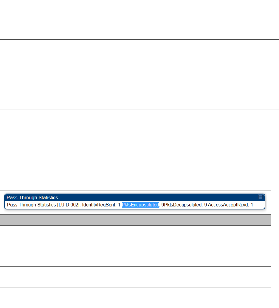
Chapter 9: Operation System statistics
Page 9-52
network stack interface 2 (RF interface) could not be sent because the
radio bridge queue was full. The packet was tossed out.
ErrBridgeFull This field indicates the total number of times the bridging table was full
and could not accept new entries.
ErrSendMsg This field displays the error message from bridge core call back routine.
ErrApFecQSend This field indicates that a packet which was received on the Ethernet
interface could not be processed because the radio bridge queue was
full and packet was tossed out.
ErrApRfQSend This field indicates that a packet which was received on the RF interface
could not be processed because the radio bridge queue was full. The
packet was tossed out.
Interpreting Pass Through Statistics
The
Statistics > Pass Through Statistics
page displays radius related statistics. The page is
applicable for PMP 450 platform AP only. The Pass Through Statistics page is explained in Table
197.
Table 197
Pass Through Statistics page attributes – AP
Attribute
Meaning
IdentityReqSent This field indicates the number of EAP Identity requests sent
through the AP with respect to an SM.
PktsEncapsulated This field indicates no of packets received from the SM which are
encapsulated by the AP.
PktsDecasulated This field indicates no of packets received from the radius server
and are decapsulated by the AP with respect to an SM
AccessAcceptRcvd This field indicates no of RADIUS Access Accept message
received by the AP with respect to an SM.
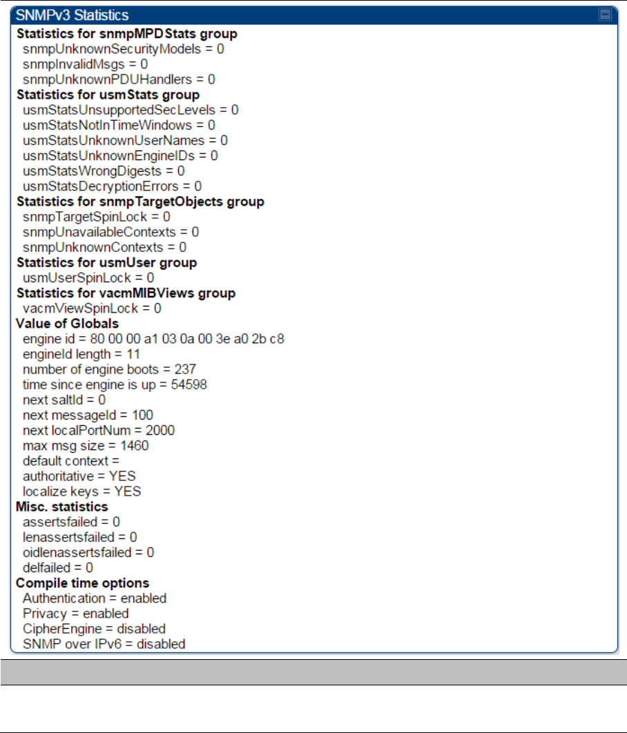
Chapter 9: Operation System statistics
Page 9-53
Interpreting SNMPv3 Statistics
The
Statistics > SNMPv3 Statistics
page displays all SNMPv3 related statistics. The page is
applicable for all platform of PMP 450 platform. The SNMPv3 Statistics page is explained in Table
198.
Table 198
SNMPv3 Statistics page attributes – AP
Attribute
Meaning
Statistics for
snmpMPDStats group SNMP Message Processing and Dispatching RFC 3412

Chapter 9: Operation System statistics
Page 9-54
snmpUnknownSecurityM
odels
The total number of packets received by the SNMP engine which
were dropped because they referenced a securityModel that was
not known to or supported by the SNMP engine.
snmpInvalidMsgs The total number of packets received by the SNMP engine which
were dropped because there were invalid or inconsistent
components in the SNMP message.
snmpUnknownPDUHandl
ers
The total number of packets received by the SNMP engine which
were dropped because the PDU contained in the packet could
not be passed to an application responsible for handling the
pduType, e.g. no SNMP application had registered for the proper
combination of the contextEngineID and the pduType.
usmStatsUnsupportedSec
Levels
The total number of packets received by the SNMP engine which
were dropped because they requested a securityLevel that was
unknown to the SNMP engine or otherwise unavailable.
usmStatsNotInTimeWind
ows
The total number of packets received by the SNMP engine which
were dropped because they appeared outside of the
authoritative SNMP engine's window.
usmStatsUnknownUserN
ames
The total number of packets received by the SNMP engine which
were dropped because they referenced a user that was not
known to the SNMP engine.
usmStatsUnknownEngine
IDs
The total number of packets received by the SNMP engine which
were dropped because they referenced a snmpEngineID that was
not known to the SNMP engine.
usmStatsWrongDigests The total number of packets received by the SNMP engine which
were dropped because they didn't contain the expected digest
value.
usmStatsDecryptionError
s
The total number of packets received by the SNMP engine which
were dropped because they could not be decrypted.
snmpTargetSpinLock This object is used to facilitate modification of table entries in the
SNMP-TARGET-MIB module by multiple managers.
snmpUnavailableContext
s
The total number of packets received by the SNMP engine which
were dropped because the context contained in the message
was unavailable.
snmpUnknownContexts The total number of packets received by the SNMP engine which
were dropped because the context contained in the message
was unknown.
usmUserSpinLock The use of usmUserSpinlock is to avoid conflicts with another
SNMP command generator application which may also be acting
on the usmUserTable.
Chapter 9: Operation System statistics
Page 9-55
vacmViewSpinLock An advisory lock used to allow cooperating SNMP Command
Generator applications to coordinate their use of the Set
operation in creating or modifying views.
snmpEngineBoots It is a count of the number of times the SNMP engine has re-
booted/re-initialized since snmpEngineID was last configured
snmpEngineTime
time since engine is up
which is the number of seconds since the snmpEngineBoots
counter was last incremented
Interpreting syslog statistics
The
Statistics > Syslog Statistics
page displays statistics of syslog messages. The page is
applicable for all modules (AP/SM/BHM/BHS). The Syslog Statistics page is explained in Table 199.
Table 199
Syslog statistics page attributes – AP/SM/BH
Attribute
Meaning
Syslog Server This displays dotted decimal or DNS name (if the DNS is
enabled) of the syslog server address.
Syslog Server Port The syslog server port (default 514) to which syslog messaging
is sent.
Syslog Status This indicates status of syslog messaging. It can be Enable or
Disabled based on configuration
Syslog Message
Transmissions
This field indicates the count of syslog messages sent to UDP
layer.
Syslog Message Dropped This field indicates the count of dropped syslog messages.
Interpreting Frame Utilization statistics
The Frame Utilization Statistics is a feature helps user to understand how effectively the RF
channel is being utilized. This feature allows to check Time Division Duplex (TDD) frame utilization
pattern and diagnose for any excessive usage in uplink or downlink direction.
This forms the first step of identifying the TDD frame utilization information. If the user finds
excessive utilization based on this stats, the second step would be to take several actions like
sectorization, tuning the uplink/downlink ratio etc. to improve RF channel utilization. Efficient use
of the TDD frame will help to achieve optimum performance of link.
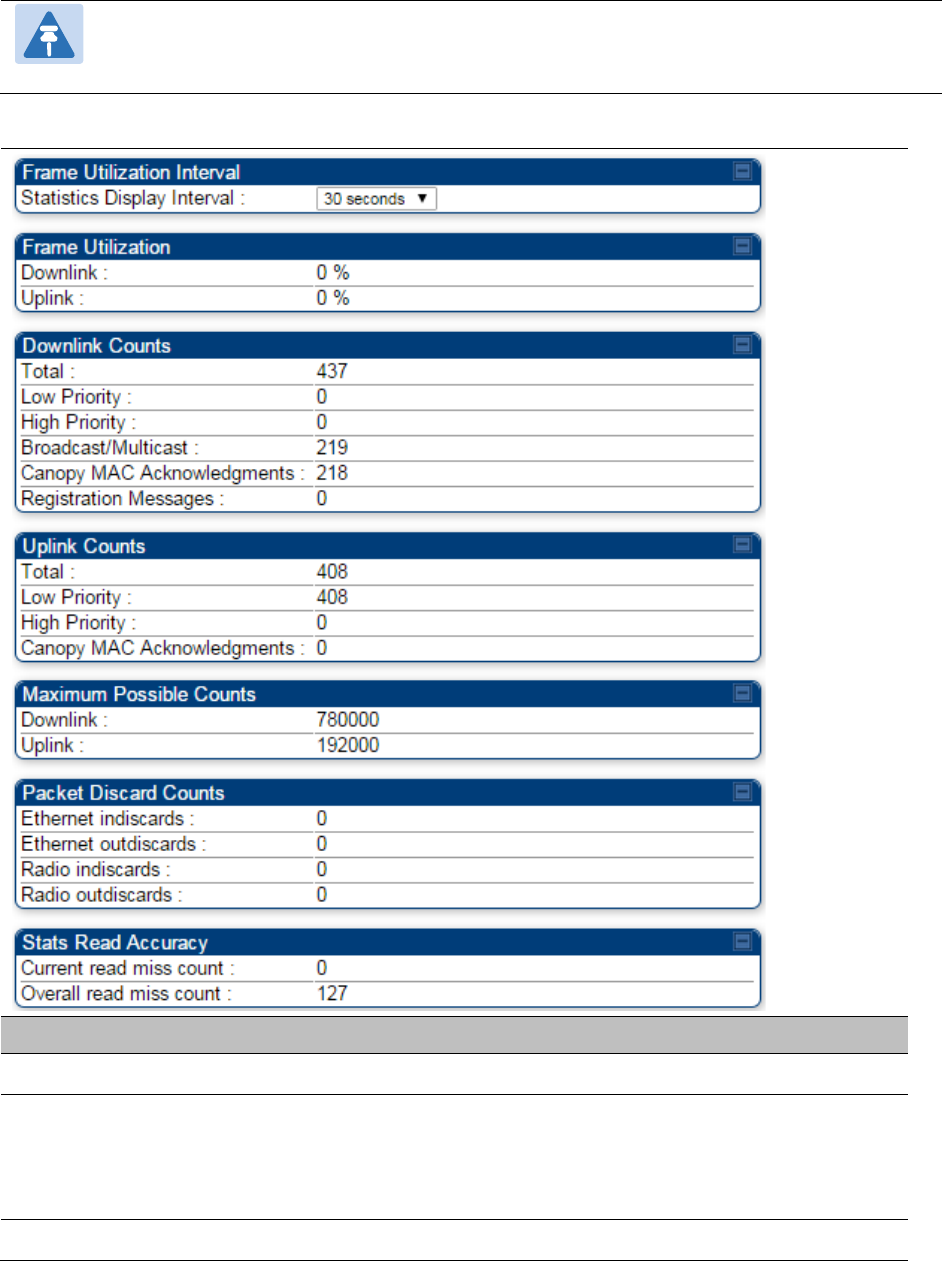
Chapter 9: Operation System statistics
Page 9-56
Note:
The backhauls (BHM and BHS) will have only the downlink scheduler based
statistics
Table 200
Frame utilization statistics
Attribute
Meaning
Frame Utilization Interval
Statistics Display interval This allows to configure timer interval to monitor and display the
frame utilization statistics. It can be configured for 30 seconds
(low interval), 3 minutes (medium interval) or 15 minutes (high
interval) based on requirement.
Frame Utilization

Chapter 9: Operation System statistics
Page 9-57
Downlink This indicates the percentage of downlink data slots used against
the maximum number of slots possible in configured interval.
Uplink This indicates the percentage of uplink data slots used against
the maximum number of uplink slots possible in configured
interval.
Downlink Counts
Total This indicates the sum of all downlink data slots used in the
configured interval.
Low Priority The number of downlink data slots used for low priority
downlink traffic.
High Priority The number of downlink data slots used for high priority
downlink traffic.
Broadcast/Multicast The number of downlink data slots used for broadcast and
multicast traffic.
Canopy MAC
Acknowledgements
The number of downlink data slots used as ACKs.
Registration and Control
message slots
The number of downlink data slots used for registration and
other control messages.
Uplink Counts
Total This indicates the sum of all uplink data slots used in configured
interval.
Low Priority The number of downlink data slots used for low priority uplink
traffic.
High Priority The number of downlink data slots used for high priority
downlink traffic.
Canopy MAC
Acknowledgements
The number of downlink data slots used as ACKs.
Maximum possible counts
Downlink This indicates the maximum possible downlink data slots. This is
based on the configuration of Channel Bandwidth, Frame period,
uplink/downlink allocation, contention slots and configured
Statistics Display interval.
Uplink This indicates the maximum possible uplink data slots. This is
based on the configuration of Channel Bandwidth, Frame period,
uplink/downlink allocation, contention slots and configured
Statistics Display interval.
Packet Discard counts