Cambium Networks 50450I Wireless Ethernet Bridge, Dual Channel OFDM MIMO Combination Access Point, Subscriber Station and Point to Point Equipment User Manual PMP PTP 450i Series User Guide
Cambium Networks Limited Wireless Ethernet Bridge, Dual Channel OFDM MIMO Combination Access Point, Subscriber Station and Point to Point Equipment PMP PTP 450i Series User Guide
Contents
- 1. Installation Guide
- 2. User Guide Part 1
- 3. User Guide Part 2
- 4. User Guide Part 3
- 5. User Guide Part 4
- 6. User Guide Part 5
- 7. User Guide Part 6
- 8. User Guide Part 7
- 9. Exhibit D Users Manual per 2 1033 b3
- 10. User Manual - Part 1
- 11. User Manual - Part 2
- 12. User Manual - Part 3
- 13. User Manual - Part 4
- 14. Users Manual - Part 5
- 15. Users Manual - Part 6
- 16. User Manual
User Guide Part 7

Chapter 9: Operation System statistics
Page 9-58
Ethernet indiscards This indicates the number of Ethernet packets discarded in the IN
queue.
Ethernet outdiscards This indicates the number of Ethernet packets discarded in the
OUT queue.
Radio indiscards This indicates the number of packets discarded over radio in the
IN queue.
Radio outdiscards This indicates the number of packets discarded over radio in the
OUT queue.

Chapter 9: Operation Radio Recovery
Page 9-59
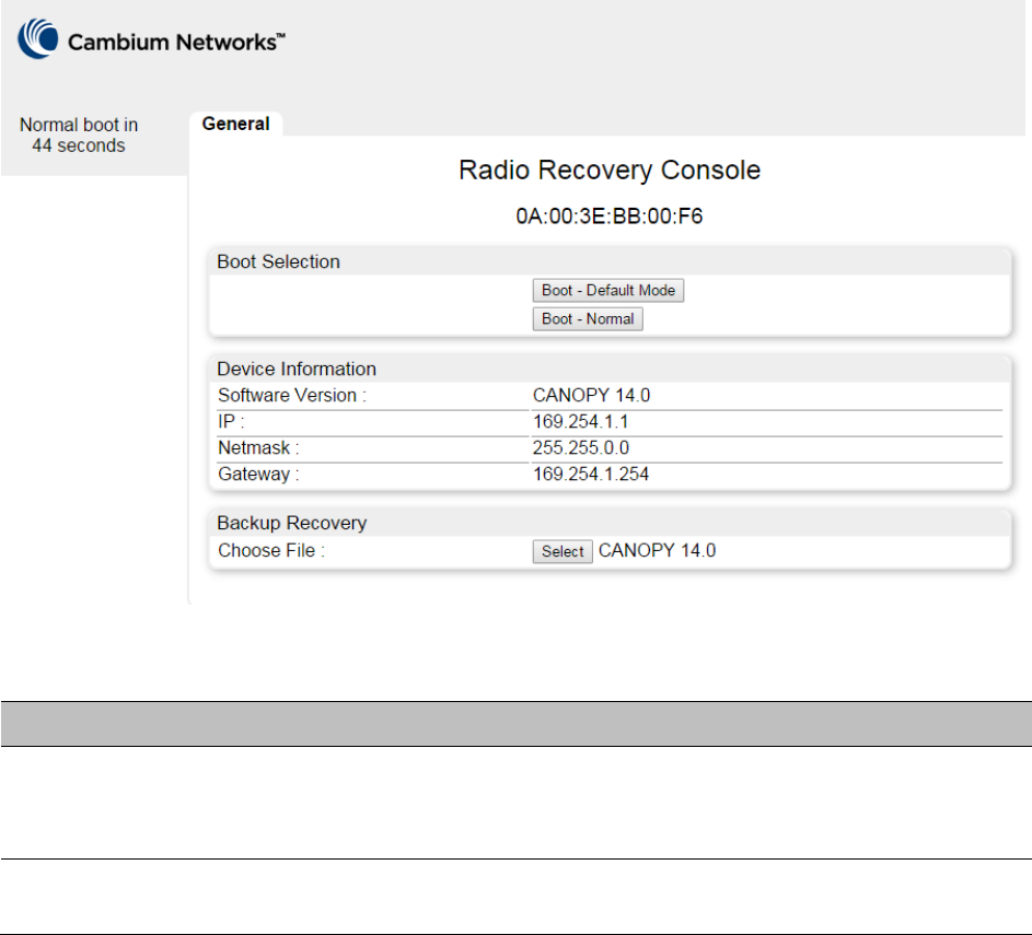
Radio Recovery
This section describes:
• How to recover a PMP/PTP 450i unit from configuration errors or software image corruption
• How to override a PMP/PTP 450 unit from forgotten IP address and password to factory default
Recovery Console – PMP/PTP 450i
Use this procedure to enter recovery console manually.
Note
The unit may enter recovery console automatically, in response to some failures.
Note
Once the unit has entered recovery, it will switch back to normal operation if no access
has been made to the recovery web page within 30 seconds.
Procedure 32
Recovery mode
1
Apply power to PSU for at least 10 seconds.
2
Remove power for two seconds.
3
Re
-apply power to the PSU.
4
When the unit is in recovery mode, access the web interface by entering the default IP
address
169.254.1.1
. The Recovery Image Warning page is displayed.
5
Review the
Boot Selection (Table 201).
6
Select a
recovery option
Chapter 9: Operation Radio Recovery
Page 9-60
Figure 151
Recovery Options page
Table 201
Recovery Options attributes
Attribute
Meaning
Boot Selection
Boot – Default Mode
: Use this option to temporarily set the IP and
Ethernet attributes to factory defaults until the next reboot.
Boot – Normal
: Use this option to reboot the unit.
IP address, Netmask,
Gateway
These fields display IP address, Netmask and Gateway of the radio while
it is in recovery or default mode.
Overriding Forgotten IP Address or Password - PMP/PTP 450
A small adjunctive product allows to temporarily override some PMP/PTP 450 ODU settings and
thereby regain control of the module by powering the module on with the plug inserted into the
unit’s synchronization (RJ11) port. This override plug is needed for access to the module in any of
the following cases:
• You have forgotten either
o the IP address assigned to the ODU.
o the password that provides access to the ODU.
• The ODU has been locked by the No Remote Access feature.
• You want local access to a module that has had the 802.3 link disabled in the Configuration
page.

Chapter 9: Operation Radio Recovery
Page 9-61
You can configure the module such that, when it senses the override plug, it responds by either
• resetting the LAN1 IP address to 169.254.1.1, allowing access through the default configuration
without changing the configuration, whereupon you will be able to view and reset any non-
default values as you wish.
• resetting all configurable parameters to their factory default values.
Using the Default/Override Plug
The following section details usage of the override plug to regain access to PMP/PTP 450 ODU.
Note
While the override plug is connected to a PMP/PTP 450 ODU, the ODU can neither
register nor allow registration of another ODU.
To regain access to the module, perform the following steps.
Procedure 33
Recovery mode
1
Insert the override plug into the RJ-11 GPS utility port of the module.
2
Power cycle by removing, then re-inserting, the Ethernet cable.
RESULT: The module boots with the default IP address of 169.254.1.1, password
fields blank, and all other configuration values as previously set.
3
Wait approximately 30 seconds for the boot to complete.
4
Remove the override plug.
5
Set passwords and IP address as desired.
6
Change configuration values if desired.
7
Click the Save Changes button.
8
Click the Reboot button.

Page 10-1
Chapter 10: Reference Information
This chapter contains reference information and regulatory notices that apply to the PMP/PTP 450
platform Series products.
The following topics are described in this chapter:
• Equipment specifications on page 10-2 contains specifications of the PMP/PTP 450 platform,
ODU specifications including RF bands, channel width and link loss.
• Data network specifications on page 10-22
shows the PMP/PTP 450 platform Ethernet interface
specifications.
• Compliance with safety standards on page 4-22 lists the safety specifications against which the
PMP/PTP 450 platform has been tested and certified. It also describes how to keep RF exposure
within safe limits.
• Country specific radio regulations on page 10-33 describes how the PMP/PTP 450 platform
complies with the radio regulations that are enforced in various countries.
• Equipment Disposal on page 10-35 describes the Equipment Disposal system for Electronic
and Electric Equipment.

Chapter 10: Reference Information Equipment specifications
Page 10-2
Equipment specifications
This section contains specifications of the AP, SM, BHM and BHS associated supplies required for
PMP/PTP 450 platform installations.
Specifications for PMP 450i AP
The PMP 450i AP conforms to the specifications listed in Table 202.
Table 202
PMP 450i AP specifications
Category
Specification
Model Number PMP 450i AP
Spectrum
Channel Spacing 5, 7, 10 and 20 MHz Channel Bandwidth
Configurable on 2.5 MHz increments
Frequency Range 902 to 928 MHz
4900 - 5925 MHz
Channel Bandwidth 902 – 928 MHz 5, 7, 10 and 20 MHz
4900 – 5925
MHz
5, 10 and 20 MHz
Interface
MAC (Media Access
Control) Layer
Cambium Proprietary
Physical Layer 2x2 MIMO OFDM
Ethernet Interface 10/100/1000BaseT, half/full duplex, rate auto negotiated
(802.3 compliant)
Protocols Used IPv4, UDP, TCP, IP, ICMP, Telnet, SNMP, HTTP, FTP
Network Management HTTP, HTTPS, Telnet, FTP, SNMP v3
VLAN 802.1ad (DVLAN Q-in-Q), 802.1Q with 802.1p priority,
dynamic port VID
Sensitivity
Nominal Receive
Sensitivity (w/ FEC) @
900 MHz 1x = -93 dBm, 2x = -88 dBm, 4x = -81 dBm, 6x = -75
dBm, 8x = -68 dBm

Chapter 10: Reference Information Equipment specifications
Page 10-3
5 MHz Channel 4.9 GHz 1x = -90 dBm, 2x = -85.7 dBm, 4x = -80 dBm, 6x = -72.4
dBm, 8x = -65.7 dBm
5.4 GHz 1x = -91 dBm, 2x = -86.3 dBm, 4x = -79.8 dBm, 6x = -
73.5 dBm, 8x = -66 dBm
5.8 GHz 1x = -91 dBm, 2x = -86.3 dBm, 4x = -79.8 dBm, 6x = -
73.5 dBm, 8x = -66 dBm
Nominal Receive
Sensitivity (w/ FEC) @
7 MHz Channel
900 MHz 1x = -91 dBm, 2x = -86 dBm, 4x = -80 dBm, 6x = -74
dBm, 8x = -67 dBm
Nominal Receive
Sensitivity (w/ FEC) @
10 MHz Channel
900 MHz 1x = -90 dBm, 2x = -84 dBm, 4x = -79 dBm, 6x = -73
dBm, 8x = -66 dBm
4.9 GHz 1x = -87.9 dBm, 2x = -84.1 dBm, 4x = -78 dBm, 6x = -
71.5 dBm, 8x = -64.8 dBm
5.4 GHz 1x = -88 dBm, 2x = -84.1 dBm, 4x = -77.1 dBm, 6x = -
71.2 dBm, 8x = -64.2 dBm
5.8 GHz 1x = -88 dBm, 2x = -84.1 dBm, 4x = -77.1 dBm, 6x = -
71.2 dBm, 8x = -64.2 dBm
Nominal Receive
Sensitivity (w/ FEC) @
20 MHz Channel
900 MHz 1x = -86 dBm, 2x = -82 dBm, 4x = -75 dBm, 6x = -69
dBm, 8x = -62 dBm
4.9 GHz 1x = -85.6 dBm, 2x = -80.4 dBm, 4x = -74.3 dBm, 6x = -
68.2 dBm, 8x = -61 dBm
5.4 GHz 1x = -86 dBm, 2x = -82 dBm, 4x = -75 dBm, 6x = -68.9
dBm, 8x = -61 dBm
5.8 GHz 1x = -86 dBm, 2x = -82 dBm, 4x = -75 dBm, 6x = -68.9
dBm, 8x = -61 dBm
Performance
ARQ Yes
Cyclic Prefix 1/16
Frame Period 2.5 ms or 5.0 ms
Modulation Levels
(Adaptive)
Modution Levels MCS SNR (in dB)
2x QPSK 10

Chapter 10: Reference Information Equipment specifications
Page 10-4
4x 16QAM 17
6x 64QAM 24
8x 256QAM 32
Latency 3 - 5 ms
Maximum Deployment
Range
Up to 40 miles (64 km)
GPS Synchronization Yes, via Autosync (CMM4), via UGPS
Quality of Service Diffserv QoS
Link Budget
Antenna Beam Width 900 MHz 65° sector antenna (Dual Slant)
5 GHz 90° (3dB rolloff) sector for integrated (Dual polarity,
H+V)
Antenna Gain (Does
not include cable loss,
~1dB)
900 MHz 13 dBi
5 GHz 16 dBi integrated 90° sector or external
Transmit Power Range 40 dB dynamic range (to EIRP limit by region) (1 dB
step)
Maximum Transmit
Power
+27 dBm combined output (for 5 GHz)
+25 dBm combined output (for 900MHz)
Physical
Sync/AUX port
RJ45 • 10/100/100BASE-T Ethernet Data
• PoE output (planned for future release)
• Sync input or output (Connection and powering of
UGPS Sync input)
Antenna Connection 50 ohm, N-type (Connectorized version only)
Surge Suppression
EN61000-4-5
EN61000-4-5: 1.2 us/50 us, 500 V voltage waveform
Recommended external surge suppressor: Cambium
Networks Model # C000000L033A
Mean Time Between
Failure
> 40 Years
Environmental IP66, IP67
Temperature /
Humidity
-40°C to +60°C (-40°F to +140°F), 0-95% non-
condensing

Chapter 10: Reference Information Equipment specifications
Page 10-5
Weight Connectorized Approx. 2.0 kg (4.5 lbs)
Integrated Approx. 2.5 kg (5.5 lbs)
Wind Survival Connectorized 322 km/h (200 mi/h)
Integrated 200 km/h (124 mi/h)
Dimension(HxWxD) Connectorized 26.0 x 13.4 x 6.4 cm (10.3” x 5.3” x 3.3”)
Integrated 37.0 x 37.0 x 6.3 cm (14.5” x 14.5” x 3.2”)
Power Consumption 15 W typical, 25 W max, 55 W max with Aux port PoE
out enabled
Input Voltage 48-59 V DC, 802.3at compliant
Mounting Wall or Pole mount with Cambium Networks Model #
N000045L002A
Security
Encryption 56-bit DES, FIPS-197 128-bit AES

Chapter 10: Reference Information Equipment specifications
Page 10-6
Specifications for PMP 450i SM
The PMP 450i SM conforms to the specifications listed in Table 203.
Table 203
PMP 450i SM specifications
Category
Specification
Model Number PMP 450i SM
Spectrum
Channel Spacing 5, 10 and 20 MHz Channel Bandwidth
Configurable on 2.5 MHz increments
Frequency Range 4900 - 5925 MHz
Channel Bandwidth 4900 – 5925
MHz
5, 10 and 20 MHz
Interface
MAC (Media Access
Control) Layer
Cambium Proprietary
Physical Layer 2x2 MIMO OFDM
Ethernet Interface 10/100/1000BaseT, half/full duplex, rate auto negotiated
(802.3 compliant)
Protocols Used IPv4, UDP, TCP, IP, ICMP, Telnet, SNMP, HTTP, FTP
Network Management HTTP, HTTPS, Telnet, FTP, SNMP v2c and v3
VLAN 802.1ad (DVLAN Q-in-Q), 802.1Q with 802.1p priority,
dynamic port VID
Sensitivity
Nominal Receive
Sensitivity (w/ FEC) @
5 MHz Channel
4.9 GHz 1x = -93 dBm, 2x = -88.5 dBm, 4x = -81.4 dBm, 6x = -75
dBm, 8x = -67.5 dBm
5.4 GHz 1x = -93 dBm, 2x = -88.7 dBm, 4x = -82.4 dBm, 6x = -
76.1 dBm, 8x = -68.5 dBm
5.8 GHz 1x = -93 dBm, 2x = -89.6 dBm, 4x = -82.6 dBm, 6x = -
76.4 dBm, 8x = -67 dBm
Nominal Receive
Sensitivity (w/ FEC) @
10 MHz Channel
4.9 GHz 1x = -89.7 dBm, 2x = -84.6 dBm, 4x = -78.6 dBm, 6x = -
71.7 dBm, 8x = -65.7 dBm
5.4 GHz 1x = -89.5 dBm, 2x = -86.3 dBm, 4x = -79.3 dBm, 6x = -
73.1 dBm, 8x = -65.4 dBm

Chapter 10: Reference Information Equipment specifications
Page 10-7
5.8 GHz 1x = -90 dBm, 2x = -85.2 dBm, 4x = -78.7 dBm, 6x = -73
dBm, 8x = -65.2 dBm
Nominal Receive
Sensitivity (w/ FEC) @
20 MHz Channel
4.9 GHz 1x = -86.8 dBm, 2x = -82 dBm, 4x = -75.7 dBm, 6x = -
69.4 dBm, 8x = -62.7 dBm
5.4 GHz 1x = -86.1 dBm, 2x = -82.3 dBm, 4x = -76 dBm, 6x = -
69.3 dBm, 8x = -62.3 dBm
5.8 GHz 1x = -87.5 dBm, 2x = -83.1 dBm, 4x = -76.3 dBm, 6x = -
69.1 dBm, 8x = -61.3 dBm
Performance
ARQ Yes
Cyclic Prefix 1/16
Frame Period 2.5 ms or 5.0 ms
Modulation Levels
(Adaptive)
Modulation Levels MCS SNR (in dB)
2x QPSK 10
4x 16QAM 17
6x 64QAM 24
8x 256QAM 32
Latency 3 - 5 ms
Maximum Deployment
Range
Up to 40 miles (64 km)
GPS Synchronization Yes, via Autosync (CMM4)
Quality of Service Diffserv QoS
Link Budget
Antenna Beam Width 10° azimuth for 23 dBi integrated antenna
Antenna Gain (Does
not include cable loss,
~1dB)
5 GHz +23 dBi H+V, integrated or external
Transmit Power Range 40 dB dynamic range (to EIRP limit by region) (1 dB
step)
Maximum Transmit
Power
+27 dBm combined output (for 5 GHz)

Chapter 10: Reference Information Equipment specifications
Page 10-8
Physical
Sync/AUX port
RJ45 • 10/100/1000BASE-T Ethernet Data
• PoE output (planned for future release)
• Sync input or output (Connection and powering of
UGPS Sync input)
Antenna Connection 50 ohm, N-type (Connectorized version only)
Surge Suppression
EN61000-4-5
EN61000-4-5: 1.2us/50us, 500 V voltage waveform
Recommended external surge suppressor: Cambium
Networks Model # C000000L033A
Mean Time Between
Failure
> 40 Years
Environmental IP66, IP67
Temperature /
Humidity
-40°C to +60°C (-40°F to +140°F), 0-95% non-
condensing
Weight Connectorized Approx. 2.0 kg (4.5 lbs)
Integrated Approx. 2.5 kg (5.5 lbs)
Wind Survival Connectorized 322 km/h (200 mi/h)
Integrated 200 km/h (124 mi/h)
Dimension(HxWxD) Connectorized 26.0 x 13.4 x 6.4 cm (10.3” x 5.3” x 3.3”)
Integrated 31.0 x 31.0 x 6.4 cm (12” x 12” x 2.5”)
Power Consumption 15 W typical, 25 W max, 55 W max with Aux port PoE
out enabled
Input Voltage 48-59 V DC, 802.3at compliant
Mounting Wall or Pole mount with Cambium Networks Model #
N000045L002A
Security
Encryption 56-bit DES, FIPS-197 128-bit AES

Chapter 10: Reference Information Equipment specifications
Page 10-9
Specifications for PTP 450i BH
The PTP 450i BH conforms to the specifications listed in Table 204.
Table 204
PTP 450i BH specifications
Category
Specification
Model Number PMP 450i BH
Spectrum
Channel Spacing 5, 10 and 20 MHz Channel Bandwidth
Configurable on 2.5 MHz increments
Frequency Range 4900 - 5925 MHz
Channel Bandwidth 5, 10 and 20 MHz
Interface
MAC (Media Access
Control) Layer
Cambium Proprietary
Physical Layer 2x2 MIMO OFDM
Ethernet Interface 10/100/1000BaseT, half/full duplex, rate auto negotiated
(802.3 compliant)
Protocols Used IPv4, UDP, TCP, IP, ICMP, Telnet, SNMP, HTTP, FTP
Network Management HTTP, HTTPS, Telnet, FTP, SNMP v2c and v3
VLAN 802.1ad (DVLAN Q-in-Q), 802.1Q with 802.1p priority,
dynamic port VID
Sensitivity
Nominal Receive
Sensitivity (w/ FEC) @
5 MHz Channel
4.9 GHz 1x = -92.7 dBm, 2x = -88.1 dBm, 4x = -81 dBm, 6x = -75
dBm, 8x = -67.8 dBm
5.4 GHz 1x = -92.4 dBm, 2x = -88.4 dBm, 4x = -81.3 dBm, 6x = -
75.5 dBm, 8x = -67.8 dBm
5.8 GHz 1x = -92.3 dBm, 2x = -87.5 dBm, 4x = -80.4 dBm, 6x = -
74 dBm, 8x = -67.2 dBm
Nominal Receive
Sensitivity (w/ FEC) @
10 MHz Channel
4.9 GHz 1x = -89.2 dBm, 2x = -85.1 dBm, 4x = -77.8 dBm, 6x = -
72 dBm, 8x = -64.9 dBm
5.4 GHz 1x = -90 dBm, 2x = -85 dBm, 4x = -78.7 dBm, 6x = -71.6
dBm, 8x = -64.4 dBm
5.8 GHz 1x = -89.9 dBm, 2x = -84.3 dBm, 4x = -78 dBm, 6x = -
71.5 dBm, 8x = -64 dBm

Chapter 10: Reference Information Equipment specifications
Page 10-10
Nominal Receive
Sensitivity (w/ FEC) @
20 MHz Channel
4.9 GHz 1x = -87.1 dBm, 2x = -82.1 dBm, 4x = -74.7 dBm, 6x = -
69.2 dBm, 8x = -61.2 dBm
5.4 GHz 1x = -86 dBm, 2x = -81.6 dBm, 4x = -74.9 dBm, 6x = -
68.4 dBm, 8x = -61 dBm
5.8 GHz 1x = -86.6 dBm, 2x = -80.4 dBm, 4x = -74.7 dBm, 6x = -
68.5 dBm, 8x = -61 dBm
Performance
ARQ Yes
Cyclic Prefix 1/16
Frame Period 2.5 ms or 5.0 ms
Modulation Levels
(Adaptive)
Modulation Levels MCS SNR (in dB)
2x QPSK 10
4x 16QAM 17
6x 64QAM 24
8x 256QAM 32
Latency 3 - 5 ms
Maximum Deployment
Range
Up to 40 miles (64 km)
GPS Synchronization Yes, via Autosync (CMM4)
Quality of Service Diffserv QoS
Link Budget
Antenna Beam Width 10° azimuth for 23 dBi integrated antenna
Antenna Gain (Does
not include cable loss,
~1dB)
5 GHz +23 dBi H+V, integrated or external
Transmit Power Range 40 dB dynamic range (to EIRP limit by region) (1 dB
step)
Maximum Transmit
Power
+27 dBm combined output
Physical
Sync/AUX port
RJ45 • 10/100/1000BASE-T Ethernet Data
• PoE output
•
Sync input or output (Connection and powering of

Chapter 10: Reference Information Equipment specifications
Page 10-11
UGPS Sync input)
Antenna Connection 50 ohm, N-type (Connectorized version only)
Surge Suppression
EN61000-4-5
EN61000-4-5: 1.2us/50us, 500 V voltage waveform
Recommended external surge suppressor: Cambium
Networks Model # C000000L033A
Mean Time Between
Failure
> 40 Years
Environmental IP66, IP67
Temperature /
Humidity
-40°C to +60°C (-40°F to +140°F), 0-95% non-
condensing
Weight Connectorized Approx. 2.0 kg (4.5 lbs)
Integrated Approx. 2.5 kg (5.5 lbs)
Wind Survival Connectorized 322 km/h (200 mi/h)
Integrated 200 km/h (124 mi/h)
Dimension(HxWxD) Connectorized 26.0 x 13.4 x 6.4 cm (10.25” x 5.25” x 3.25”)
Integrated 31.0 x 31.0 x 6.4 cm (12” x 12” x 2.5”)
Power Consumption 15 W typical, 25 W max, 55 W max with Aux port PoE
out enabled
Input Voltage 48-59 V DC, 802.3at compliant
Mounting Wall or Pole mount with Cambium Networks Model #
N000045L002A
Security
Encryption 56-bit DES, FIPS-197 128-bit AES

Chapter 10: Reference Information Equipment specifications
Page 10-12
Specifications for PMP 450 AP
The PMP 450 AP conforms to the specifications listed in Table 205.
Table 205
PMP 450 AP specifications
Category
Specification
Model Number PMP 450 AP
Spectrum
Channel Spacing 5, 10 and 20 MHz Channel Bandwidth
Configurable on 2.5 MHz increments
Frequency Range 2.4 GHz 2400 – 2483.5 MHz
3.5 GHz 3300 – 3600 MHz
3.65 GHz 3500 – 3850 MHz
5 GHz 5470 – 5875 MHz
Channel Bandwidth 3.5 and 3.65 GHz 5, 7, 10 and 20 MHz
2.4 and 5 GHz 5, 10 and 20 MHz
OFDM Subcarriers
512 FFT
Interface
MAC (Media Access
Control) Layer
Cambium Proprietary
Physical Layer 2x2 MIMO OFDM
Ethernet Interface 10/100 BaseT, half/full duplex, rate auto negotiated
(802.3 compliant)
Protocols Used IPv4, UDP, TCP, IP, ICMP, Telnet, SNMP, HTTP, FTP
Network Management HTTP, HTTPS, Telnet, FTP, SNMP v3
VLAN 802.1ad (DVLAN Q-in-Q), 802.1Q with 802.1p
priority, dynamic port VID
Sensitivity
Nominal Receive
Sensitivity (w/ FEC) @
5 MHz Channel
2.4 GHz
1x = -91 dBm, 2x = -91 dBm, 4x = -85 dBm, 6x = -78
dBm, 8x = -70 dBm
3.5 GHz 1x = -92 dBm, 2x = -92 dBm, 4x = -86 dBm, 6x = -79

Chapter 10: Reference Information Equipment specifications
Page 10-13
dBm, 8x = -71 dBm
3.65 GHz 1x = -90 dBm, 2x = -90 dBm, 4x = -83 dBm, 6x = -76
dBm, 8x = -68 dBm
5.4 GHz 1x = -89 dBm, 2x = -89 dBm, 4x = -81 dBm, 6x = -75
dBm, 8x = -66 dBm
5.8 GHz 1x = -88 dBm, 2x = -88 dBm, 4x = -81 dBm, 6x = -75
dBm, 8x = -65 dBm
Nominal Receive
Sensitivity (w/ FEC) @
7 MHz Channel
3.5 GHz 1x = -90 dBm, 2x = -90 dBm, 4x = -83 dBm, 6x = -77
dBm, 8x = -71 dBm
3.65 GHz 1x = -89 dBm, 2x = -89 dBm, 4x = -82 dBm, 6x = -75
dBm, 8x = -67 dBm
Nominal Receive
Sensitivity (w/ FEC) @
10 MHz Channel
2.4 GHz 1x = -88 dBm, 2x = -88 dBm, 4x = -81 dBm, 6x = -75
dBm, 8x = -69 dBm
3.5 GHz 1x = -88 dBm, 2x = -88 dBm, 4x = -81 dBm, 6x = -76
dBm, 8x = -68 dBm
3.65 GHz 1x = -86 dBm, 2x = -86 dBm, 4x = -80 dBm, 6x = -73
dBm, 8x = -66 dBm
5.4 GHz 1x = -84 dBm, 2x = -84 dBm, 4x = -78 dBm, 6x = -72
dBm, 8x = -63 dBm
5.8 GHz 1x = -84 dBm, 2x = -84 dBm, 4x = -77 dBm, 6x = -71
dBm, 8x = -63 dBm
Nominal Receive
Sensitivity (w/ FEC) @
20 MHz Channel
2.4 GHz 1x = -85 dBm, 2x = -85 dBm, 4x = -79 dBm, 6x = -72
dBm, 8x = -66 dBm
3.5 GHz 1x = -85 dBm, 2x = -85 dBm, 4x = -79 dBm, 6x = -72
dBm, 8x = -65 dBm
3.65 GHz 1x = -86 dBm, 2x = -86 dBm, 4x = -78 dBm, 6x = -71
dBm, 8x = -63 dBm
5.4 GHz 1x = -81 dBm, 2x = -81 dBm, 4x = -75 dBm, 6x = -68
dBm, 8x = -59 dBm
5.8 GHz 1x = -82 dBm, 2x = -82 dBm, 4x = -75 dBm, 6x = -69
dBm, 8x = -60 dBm
Performance
Subscribers Per Sector Up to 238
ARQ Yes

Chapter 10: Reference Information Equipment specifications
Page 10-14
Cyclic Prefix 1/16
Frame Period 2.5 ms or 5.0 ms
Modulation Levels
(Adaptive)
Modulation
Levels
MCS SNR (in dB)
2x QPSK 10
4x 16QAM 17
6x 64QAM 24
8x 256QAM 32
Latency 3 - 5 ms for 2.5 ms Frame Period
6-10 ms for 5.0 ms Frame Period
Maximum Deployment Range Up to 40 miles (64 km)
Packets Per Second 12,500
GPS Synchronization Yes, via CMM3, CMM4 or UGPS
Quality of Service Diffserv QoS
Link Budget
Antenna Gain (Does
not include cable loss,
~1dB)
2.4 GHz 18 dBi Dual Slant
3.5 GHz 16 dBi Dual Slant
3.65 GHz 16 dBi Dual Slant
5 GHz 17 dBi Horizontal and Vertical
Combined Transmit
Power
-30 to +22 dBm (to EIRP limit by region) in 1 dB-
configurable intervals (2.4 GHz, 5 GHz)
-30 to +25 dBm (to EIRP limit by region) in 1 dB-
configurable intervals (3.5 GHz)
-30 to +25 dBm (to EIRP limit by region and channel
bandwidth) in 1 dB-configurable intervals (3.6 GHz)
Maximum Transmit
Power
22 dBm combined OFDM (2.4 GHz, 5 GHz)
(dependent upon Region Code setting)
25 dBm combined OFDM (3.5 GHz, 3.6 GHz),
(dependent upon Region Code setting)
Physical
Wind Survival
2.4 GHz 216 km/hour (135 mi/hour)

Chapter 10: Reference Information Equipment specifications
Page 10-15
3.5 GHz 216 km/hour (135 mi/hour)
3.65 GHz 216 km/hour (135 mi/hour)
5 GHz 190 km/hour (118 mi/hour)
Antenna Connection 50 ohm, N-type (Connectorized version only)
Environmental IP66, IP67
Temperature /
Humidity
-40°C to +60°C (-40°F to +140°F) /
0-95% non-condensing
Weight 2.4 GHz 15 kg (33 lbs) with antenna
2.5 kg (5.5 lbs) without antenna
3.5 GHz 15 kg (33 lbs) with antenna
2.5 kg (5.5 lbs) without antenna
3.6 GHz 15 kg (33 lbs) with antenna
2.5 kg (5.5 lbs) without antenna
5 GHz 5.9 kg (13 lbs) with antenna
2.5 kg (5.5 lbs) without antenna
Dimension(HxWxD) 2.4 GHz Radio: 27 x 21 x 7 cm (10.6” x 8.3” x 2.8”)
Antenna: 112.2 x 24.5 x 11.7 cm (44.2” x 9.6” x 4.6”)
3.5 GHz
3.6 GHz
5 GHz Radio: 27 x 21 x 7 cm (10.6” x 8.3” x 2.8”)
Antenna: 51 x 13 x 7.3 cm (20.2” x 5.1” x 2.9”)
Power Consumption 14 W
Input Voltage 22 to 32 VDC
Security
Encryption 56-bit DES, AES

Chapter 10: Reference Information Equipment specifications
Page 10-16
Specifications for PMP 450 SM
The PMP 450 SM conforms to the specifications listed in Table 206.
Table 206
PMP 450 SM specifications
Category
Specification
Model Number PMP 450 SM
Spectrum
Channel Spacing 5, 7, 10 and 20 MHz Channel Bandwidth
Configurable on 2.5 MHz increments
Frequency Range 900 MHz 902 – 928 MHz
2.4 GHz 2400 – 2483.5 MHz
3.5 GHz 3300 – 3600 MHz
3.65 GHz 3500 – 3850 MHz
5 GHz 5470 – 5875 MHz
Channel Bandwidth 900 MHz, 3.5 GHz
and 3.65 GHz
5, 7, 10 and 20 MHz
2.4 and 5 GHz 5, 10 and 20 MHz
OFDM Subcarriers
512 FFT
Interface
MAC (Media Access
Control) Layer
Cambium Proprietary
Physical Layer 2x2 MIMO OFDM
Ethernet Interface 10/100 BaseT, half/full duplex, rate auto negotiated
(802.3 compliant)
Protocols Used IPv4, UDP, TCP, IP, ICMP, Telnet, SNMP, HTTP, FTP
Network Management HTTP, HTTPS, Telnet, FTP, SNMP v3
VLAN 802.1ad (DVLAN Q-in-Q), 802.1Q with 802.1p
priority, dynamic port VID
Sensitivity
Nominal Receive
Sensitivity (w/ FEC) @
900 MHz 1x = -91 dBm, 2x = -91 dBm, 4x = -85 dBm, 6x = -78
dBm, 8x = -70 dBm

Chapter 10: Reference Information Equipment specifications
Page 10-17
5 MHz Channel 2.4 GHz
1x = -91 dBm, 2x = -91 dBm, 4x = -85 dBm, 6x = -78
dBm, 8x = -70 dBm
3.5 GHz 1x = -92 dBm, 2x = -92 dBm, 4x = -86 dBm, 6x = -79
dBm, 8x = -71 dBm
3.65 GHz 1x = -90 dBm, 2x = -90 dBm, 4x = -83 dBm, 6x = -76
dBm, 8x = -68 dBm
5.4 GHz 1x = -89 dBm, 2x = -89 dBm, 4x = -81 dBm, 6x = -75
dBm, 8x = -66 dBm
5.8 GHz 1x = -88 dBm, 2x = -88 dBm, 4x = -81 dBm, 6x = -75
dBm, 8x = -65 dBm
Nominal Receive
Sensitivity (w/ FEC) @
7 MHz Channel
900 MHz 1x = -91 dBm, 2x = -84 dBm, 4x = -83 dBm, 6x = -77
dBm, 8x = -71 dBm
3.5 GHz 1x = -90 dBm, 2x = -90 dBm, 4x = -83 dBm, 6x = -77
dBm, 8x = -71 dBm
3.65 GHz 1x = -89 dBm, 2x = -89 dBm, 4x = -82 dBm, 6x = -75
dBm, 8x = -67 dBm
Nominal Receive
Sensitivity (w/ FEC) @
10 MHz Channel
900 MHz 1x = -90 dBm, 2x = -83 dBm, 4x = -80 dBm, 6x = -74
dBm, 8x = -68 dBm
2.4 GHz 1x = -88 dBm, 2x = -88 dBm, 4x = -81 dBm, 6x = -75
dBm, 8x = -69 dBm
3.5 GHz 1x = -88 dBm, 2x = -88 dBm, 4x = -81 dBm, 6x = -76
dBm, 8x = -68 dBm
3.65 GHz 1x = -86 dBm, 2x = -86 dBm, 4x = -80 dBm, 6x = -73
dBm, 8x = -66 dBm
5.4 GHz 1x = -84 dBm, 2x = -84 dBm, 4x = -78 dBm, 6x = -72
dBm, 8x = -63 dBm
5.8 GHz 1x = -84 dBm, 2x = -84 dBm, 4x = -77 dBm, 6x = -71
dBm, 8x = -63 dBm
Nominal Receive
Sensitivity (w/ FEC) @
20 MHz Channel
900 MHz 1x = -87 dBm, 2x = -80 dBm, 4x = -77 dBm, 6x = -72
dBm, 8x = -65 dBm
2.4 GHz 1x = -85 dBm, 2x = -85 dBm, 4x = -79 dBm, 6x = -71
dBm, 8x = -62 dBm
3.5 GHz 1x = -85 dBm, 2x = -85 dBm, 4x = -79 dBm, 6x = -72
dBm, 8x = -65 dBm
3.65 GHz 1x = -86 dBm, 2x = -86 dBm, 4x = -78 dBm, 6x = -71
dBm, 8x = -63 dBm
5.4 GHz 1x = -81 dBm, 2x = -81 dBm, 4x = -75 dBm, 6x = -68

Chapter 10: Reference Information Equipment specifications
Page 10-18
dBm, 8x = -59 dBm
5.8 GHz 1x = -82 dBm, 2x = -82 dBm, 4x = -75 dBm, 6x = -69
dBm, 8x = -60 dBm
Performance
Subscribers Per Sector Up to 238
ARQ Yes
Cyclic Prefix 1/16
Frame Period 2.5 ms or 5.0 ms
Modulation Levels
(Adaptive)
Modulation Levels MCS SNR (in dB)
2x QPSK 10
4x 16QAM 17
6x 64QAM 24
8x 256QAM 32
Latency 3 - 5 ms for 2.5 ms Frame Period
6-10 ms for 5.0 ms Frame Period
Maximum Deployment Range Up to 40 miles (64 km)
GPS Synchronization Yes
Quality of Service Diffserv QoS
Link Budget
Antenna Gain (Does
not include cable loss,
~1dB)
900 MHz 12 dBi Yagi antenna
2.4 GHz 7 dBi Dual Slant, integrated patch
3.5 GHz 8 dBi Dual Slant, integrated patch
3.65 GHz 8 dBi Dual Slant, integrated patch
5 GHz 9 dBi H+V, integrated patch
Combined Transmit
Power
-30 to +22 dBm (to EIRP limit by region) – 2.4 GHz, 5
GHz
-30 to +25 dBm (to EIRP limit by region) – 3.5 GHz,
3.6 GHz
Maximum Transmit
Power
22 dBm combined OFDM (2.4 GHz, 5 GHz)
(dependent upon Region Code setting)

Chapter 10: Reference Information Equipment specifications
Page 10-19
25 dBm combined OFDM (900 MHz, 3.5 GHz, 3.6
GHz), (dependent upon Region Code setting)
Reflector antenna gain 2.4 GHz +12 dBi
3.5 GHz +11 dBi
3.65 GHz +11 dBi
5 GHz +15 dBi
Other antenna (5 GHz
only)
CLIP Gain +8 dBi
LENS Gain +5.5 dBi
Dish +17 dBi
Physical
Wind Survival
190 km/hour (118 mi/hour)
Antenna Connection 50 ohm, N-type (Connectorized version only)
Environmental IP55
Temperature /
Humidity
-40°C to +60°C (-40°F to +140°F) /
0-95% non-condensing
Weight 2.4 GHz 15 kg (33 lbs) with antenna
2.5 kg (5.5 lbs) without antenna
3.5 GHz 15 kg (33 lbs) with antenna
2.5 kg (5.5 lbs) without antenna
3.6 GHz 15 kg (33 lbs) with antenna
2.5 kg (5.5 lbs) without antenna
5 GHz 5.9 kg (13 lbs) with antenna
2.5 kg (5.5 lbs) without antenna
Dimensions (H x W x D) 30 x 9 x 9 cm (11.75” x 3.4” x 3.4”)
Power Consumption 12 W
Input Voltage 20 to 32 VDC
Security
Encryption 56-bit DES, AES
Chapter 10: Reference Information Equipment specifications
Page 10-20
PSU specifications
The PMP/PTP 450i AC+DC Enhanced Power Injector conforms to the specifications listed in Table
207.
Table 207
PMP/PTP 450i
AC power Injector
specifications
Category
Specification
Dimensions 137 mm (5.4 in) x 56 mm (2.2 in) x 38 mm (1.5 in)
Weight 0.240 Kg (0.5 lbs)
Temperature 0°C to +40°C
Humidity 90% non-condensing
Waterproofing Not waterproof
Altitude Sea level to 5000 meters (16000 ft)
AC Input Min 90 V AC, 57 – 63 Hz, max 264 V AC, 47 – 53 Hz.
DC output voltage to the ODU 55V +/- 5%
AC connector IEC-320-C8
Efficiency Better than 85%, efficiency level ‘V’
Over Current Protection Hiccup current limiting, trip point set between 120% to
150% of full load current
Hold up time At least 10 milliseconds
Warning
Do not use above PSU to power up other than 450 platform radios.
The PMP/PTP 450 power supply conforms to the specifications listed in Table 208.
Table 208
PMP/PTP 450
power supply
specifications (part number: N000900L001A)
Category
Specification
Dimensions 118 mm (4.66 in) x 45 mm (1.75 in) x 32 mm (1.25 in)
Weight 0.240 Kg (0.5 lbs)
Temperature 0°C to +40°C
Humidity 20 to 90%
AC Input 90-264 VAC, 47 – 63 Hz, 0.5 A rms at 120 VAC, 0.25 A rms
at 240 VAC.

Chapter 10: Reference Information Equipment specifications
Page 10-21
DC output voltage to the ODU 30 V ± 5%
AC connector IEC-320-C8
Efficiency Better than 85%, efficiency level ‘V’
Over Current Protection Short circuit, with auto recovery; Should restart between
every 0.5 to 2 sec.
Hold up time 10mS min at max load, 120VAC
Note
The 30V PSU (part number: #N000900L001A) has to be used for PMP 450 900 MHz SM.

Chapter 10: Reference Information Data network specifications
Page 10-22
Data network specifications
This section contains specifications of the PMP/PTP 450 platform Ethernet interface.
Ethernet interface
PMP/PTP 450i
The PMP/PTP 450i Ethernet port conforms to the specifications listed in
Table 209.
Table 209
PMP/PTP 450i Main and Aux Ethernet bridging specifications
Ethernet Bridging
Specification
Protocol IEEE 802.3 compatible
QoS IEEE 802.1p, IEEE 802.1Q, IEEE 802.1ad, DSCP IPv4
Main Ethernet port 10/100/1000 BaseT, half/full duplex, rate auto negotiated
Aux Ethernet port 10/100 BaseT, half/full duplex, rate auto negotiated
Maximum Ethernet Frame
Size
1700 Bytes
PMP/PTP 450
Table 210
PMP/PTP 450 Ethernet bridging specifications
Ethernet Bridging
Specification
Protocol IEEE 802.3 compatible
QoS IEEE 802.1p, IEEE 802.1Q, IEEE 802.1ad, DSCP IPv4
Interface 10/100/1000 BaseT, half/full duplex, rate auto negotiated
Maximum Ethernet Frame
Size
1700 Bytes
Note
Practical Ethernet rates depend on network configuration, higher layer protocols and
platforms used.
Over the air throughput is restricted to the rate of the Ethernet interface at the
receiving end of the link.
Chapter 10: Reference Information Wireless specifications
Page 10-23
Wireless specifications
This section contains specifications of the PMP/PTP 450 platform wireless interface. These
specifications include RF bands, channel bandwidth, spectrum settings, maximum power and link
loss.
General wireless specifications
The wireless specifications that apply to all PMP/PTP 450 platform variants are listed under Table
211.
Table 211
PMP/PTP 450 platform wireless specifications
Item
Specification
Channel selection Manual selection (fixed frequency).
Manual power control To avoid interference to other users of the band, maximum power
can be set lower than the default power limit.
Duplex scheme Adaptive TDD
Range Band Platform Range
900 MHz PMP 450i AP
PMP 450 SM
40 mi / 64 km
2.4 GHz PMP 450 40 mi / 64 km
3.5 GHz PMP/PTP 450 40 mi / 64 km
3.65 GHz PMP/PTP 450 40 mi / 64 km
5 GHz PMP/PTP 450 and
450i
40 mi / 64 km
Over-the-air encryption DES, AES
Error Correction Rate 3/4 RS coder

Chapter 10: Reference Information Wireless specifications
Page 10-24
Link Range
Example of the link ranges for PMP and PTP modes are provided in below tables. These assume
the transmit power is not limited by the country of operation for the selected band.
PMP 450i
Table 212
Link range – PMP 5.8 GHz link, 20 MHz Channel Bandwidth, 2.5 ms frame duration,
antenna gain of 17 dBi at AP and 23 dBi at the SM
Parameter
Range Details (km)
1x
2x
4x
6x
8x
Modulation QPSK-
MIMO-A
QPSK-
MIMO-B
16QAM-
MIMO-B
64QAM-
MIMO-B
256QAM-
MIMO-B
Max. LOS
(no fade margin) 239.6 68.3 35.4 16.8 6.7
Max. nLOS
(additional 5 dB link loss) 134.8 38.4 19.9 9.4 3.8
Max. NLOS1
(additional 15 dB link loss) 42.6 12.1 6.3 3.0 1.2
Max. NLOS2
(additional 25 dB link loss) 13.5 3.8 2.0 0.9 0.4
PTP 450i
Table 213
Link range – PTP 5.8 GHz link, 20 MHz Channel Bandwidth, 2.5 ms frame duration,
antenna gain of 23 dBi at each end
Parameter
Range Details (km)
1x
2x
4x
6x
8x
Modulation QPSK-
MIMO-A
QPSK-
MIMO-B
16QAM-
MIMO-B
64QAM-
MIMO-B
256QAM-
MIMO-B
Max. LOS
(no fade margin) 239.6 136.3 70.7 33.5 13.3
Max. nLOS
(additional 5 dB link loss) 134.8 76.7 39.8 18.8 7.5
Max. NLOS1
(additional 15 dB link loss) 42.6 24.2 12.6 6.0 2.4
Max. NLOS2
(additional 25 dB link loss) 13.5 7.7 4.0 1.9 0.7

Chapter 10: Reference Information Wireless specifications
Page 10-25
PMP 450
Table 214
Link range – PMP 5.8 GHz link, 20 MHz Channel Bandwidth, 2.5 ms frame duration,
antenna gain of 17 dBi at AP
Parameter
SM type
Range Details (mi / km)
1x
2x
4x
6x
8x
Modulation QPSK-
MIMO-A
QPSK-
MIMO-B
16QAM-
MIMO-B
64QAM-
MIMO-B
256QAM-
MIMO-B
Max. LOS
(no fade margin) Integrated 7.0 mi /
11.3 km
5.0 mi /
8.0 km
2.3 mi /
3.6 km
1.1 mi /
1.8 km
0.4 mi /
0.6 km
Integrated Dish
(+17 dB) SM 450d
40.0 mi /
64.0 km
31.5 mi /
50.4 km
14.2 mi /
22.8 km
7.1 mi /
11.4 km
2.5 mi /
4.0 km
CLIP
(+8 dB)
19.9 mi /
31.8 km
14.1 mi /
22.5 km
6.4 mi /
10.2 km
3.2 mi /
5.1 km
1.1 mi /
1.8 km
Reflector Dish
(+16 dB)
40.0 mi /
64.0 km
31.5 mi /
50.4 km
14.2 mi /
22.8 km
7.1 mi /
11.4 km
2.5 mi /
4.0 km
Max. nLOS
(additional 5 dB
link loss)
Integrated 4.0 mi /
6.3 km
2.8 mi /
4.5 km
1.3 mi /
2.0 km
0.6 mi /
1.0 km
0.2 mi /
0.4 km
Integrated Dish
(+17 dB) SM 450d
25.0 mi /
40.0 km
17.7 mi /
28.3 km
8.0 mi /
12.8 km
4.0 mi /
6.4 km
1.4 mi /
2.2 km
CLIP
(+8 dB)
11.2 mi /
17.9 km
7.9 mi /
12.7 km
3.6 mi /
5.7 km
1.8 mi /
2.9 km
0.6 mi /
1.0 km
Reflector Dish
(+16 dB)
25.0 mi /
40.0 km
17.7 mi /
28.3 km
8.0 mi /
12.8 km
4.0 mi /
6.4 km
1.4 mi /
2.2 km
Max. NLOS1
(additional 15 dB
link loss)
Integrated 1.3 mi /
2.0 km
0.9 mi /
1.4 km
0.4 mi /
0.6 km
0.2 mi /
0.3 km
0.1 mi /
0.1 km
Integrated Dish
(+17 dB) SM 450d
7.9 mi /
12.7 km
5.6 mi /
9.0 km
2.5 mi /
4.0 km
1.3 mi /
2.0 km
0.4 mi /
0.7 km
CLIP
(+8 dB)
3.5 mi /
5.7 km
2.5 mi /
4.0 km
1.1 mi /
1.8 km
0.6 mi /
0.9 km
0.2 mi /
0.3 km
Reflector Dish
(+16 dB)
7.9 mi /
12.7 km
5.6 mi /
9.0 km
2.5 mi /
4.0 km
1.3 mi /
2.0 km
0.4 mi /
0.7 km
Max. NLOS2
(additional 25 dB
link loss)
Integrated 0.4 mi /
0.6 km
0.3 mi /
0.4 km
0.1 mi /
0.2 km
0.1 mi /
0.1 km
0.0 mi /
0.0 km
Integrated Dish
(+17 dB) SM 450d
2.5 mi /
4.0 km
1.8 mi /
2.8 km
0.8 mi /
1.3 km
0.4 mi /
0.6 km
0.1 mi /
0.2 km
CLIP 1.1 mi / 0.8 mi / 0.4 mi / 0.2 mi / 0.1 mi /

Chapter 10: Reference Information Wireless specifications
Page 10-26
(+8 dB)
1.8 km 1.3 km 0.6 km 0.3 km 0.1 km
Reflector Dish
(+16 dB)
2.5 mi /
4.0 km
1.8 mi /
2.8 km
0.8 mi /
1.3 km
0.4 mi /
0.6 km
0.1 mi /
0.2 km
Table 215
Link range – PMP 5.4 GHz link, 20 MHz Channel Bandwidth, 2.5 ms frame duration,
antenna gain of 17 dBi at AP
Parameter
SM type
Range Details (mi / km)
1x
2x
4x
6x
8x
Modulation QPSK-
MIMO-A
QPSK-
MIMO-B
16QAM-
MIMO-B
64QAM-
MIMO-B
256QAM-
MIMO-B
Max. LOS
(no fade margin) Integrated 6.6 mi /
10.6 km
4.7 mi /
7.5 km
2.4 mi /
3.9 km
1.0 mi /
1.6 km
0.4 mi /
0.6 km
Integrated Dish
(+17 dB) SM 450d
40.0 mi /
64.0 km
29.5 mi /
47.2 km
15.2 mi /
24.3 km
6.5 mi /
10.4 km
2.3 mi /
3.7 km
CLIP
(+8 dB)
16.6 mi /
26.5 km
11.7 mi /
18.8 km
6.1 mi /
9.7 km
2.6 mi /
4.1 km
0.9 mi /
1.5 km
Reflector Dish
(+16 dB)
40.0 mi /
64.0 km
29.5 mi /
47.2 km
15.2 mi /
24.3 km
6.5 mi /
10.4 km
2.3 mi /
3.7 km
Max. nLOS
(additional 5 dB
link loss)
Integrated 3.7 mi /
5.9 km
2.6 mi /
4.2 km
1.4 mi /
2.2 km
0.6 mi /
0.9 km
0.2 mi /
0.3 km
Integrated Dish
(+17 dB) SM 450d
23.4 mi /
37.5 km
16.6 mi /
26.5 km
8.6 mi /
13.7 km
3.7 mi /
5.9 km
1.3 mi /
2.1 km
CLIP
(+8 dB)
9.3 mi /
14.9 km
6.6 mi /
10.6 km
3.4 mi /
5.4 km
1.5 mi /
2.3 km
0.5 mi /
0.8 km
Reflector Dish
(+16 dB)
23.4 mi /
37.5 km
16.6 mi /
26.5 km
8.6 mi /
13.7 km
3.7 mi /
5.9 km
1.3 mi /
2.1 km
Max. NLOS1
(additional 15 dB
link loss)
Integrated 1.2 mi /
1.9 km
0.8 mi /
1.3 km
0.4 mi /
0.7 km
0.2 mi /
0.3 km
0.1 mi /
0.1 km
Integrated Dish
(+17 dB) SM 450d
7.4 mi /
11.9 km
5.2 mi /
8.4 km
2.7 mi /
4.3 km
1.2 mi /
1.9 km
0.4 mi /
0.7 km
CLIP
(+8 dB)
2.9 mi /
4.7 km
2.1 mi /
3.3 km
1.1 mi /
1.7 km
0.5 mi /
0.7 km
0.2 mi /
0.3 km
Reflector Dish
(+16 dB)
7.4 mi /
11.9 km
5.2 mi /
8.4 km
2.7 mi /
4.3 km
1.2 mi /
1.9 km
0.4 mi /
0.7 km
Max. NLOS2
(additional 25 dB Integrated 0.4 mi /
0.6 km
0.3 mi /
0.4 km
0.1 mi /
0.2 km
0.1 mi /
0.1 km
0.0 mi /
0.0 km

Chapter 10: Reference Information Wireless specifications
Page 10-27
link loss)
Integrated Dish
(+17 dB) SM 450d
2.3 mi /
3.7 km
1.7 mi /
2.7 km
0.9 mi /
1.4 km
0.4 mi /
0.6 km
0.1 mi /
0.2 km
CLIP
(+8 dB)
0.9 mi /
1.5 km
0.7 mi /
1.1 km
0.3 mi /
0.5 km
0.1 mi /
0.2 km
0.1 mi /
0.1 km
Reflector Dish
(+16 dB)
2.3 mi /
3.7 km
1.7 mi /
2.7 km
0.9 mi /
1.4 km
0.4 mi /
0.6 km
0.1 mi /
0.2 km
Table 216
Link range – PMP 2.4 GHz link, 20 MHz Channel Bandwidth, 2.5 ms frame duration,
antenna gain of 18 dBi at AP
Parameter
SM type
Range Details (mi / km)
1x
2x
4x
6x
8x
Modulation QPSK-
MIMO-A
QPSK-
MIMO-B
16QAM-
MIMO-B
64QAM-
MIMO-B
256QAM-
MIMO-B
Max. LOS
(no fade margin) Integrated 22.1 mi /
35.4 km
15.7 mi /
25.1 km
7.6 mi /
12.1 km
3.6 mi /
5.7 km
1.7 mi /
2.8 km
Reflector Dish
(+12 dB)
40.0 mi /
64.0 km
40.0 mi /
64.0 km
30.2 mi /
48.4 km
14.3 mi /
22.9 km
6.8 mi /
11.0 km
Max. nLOS
(additional 5 dB
link loss)
Integrated 12.5 mi /
19.9 km
8.8 mi /
14.1 km
4.3 mi /
6.8 km
2.0 mi /
3.2 km
1.0 mi /
1.5 km
Reflector Dish
(+12 dB)
40.0 mi /
64.0 km
35.1 mi /
56.2 km
17.0 mi /
27.2 km
8.0 mi /
12.9 km
3.8 mi /
6.2 km
Max. NLOS1
(additional 15 dB
link loss)
Integrated 3.9 mi /
6.3 km
2.8 mi /
4.5 km
1.3 mi /
2.2 km
0.6 mi /
1.0 km
0.3 mi /
0.5 km
Reflector Dish
(+12 dB)
15.7 mi /
25.1 km
11.1 mi /
17.8 km
5.4 mi /
8.6 km
2.5 mi /
4.1 km
1.2 mi /
1.9 km
Max. NLOS2
(additional 25 dB
link loss)
Integrated 1.2 mi /
2.0 km
0.9 mi /
1.4 km
0.4 mi /
0.7 km
0.2 mi /
0.3 km
0.1 mi /
0.2 km
Reflector Dish
(+12 dB)
5.0 mi /
7.9 km
3.5 mi /
5.6 km
1.7 mi /
2.7 km
0.8 mi /
1.3 km
0.4 mi /
0.6 km

Chapter 10: Reference Information Wireless specifications
Page 10-28
Table 217
Link range – PMP 3.5 GHz link, 20 MHz Channel Bandwidth, 2.5 ms frame duration,
antenna gain of 16 dBi at AP
Parameter
SM type
Range Details (mi / km)
1x
2x
4x
6x
8x
Modulation QPSK-
MIMO-A
QPSK-
MIMO-B
16QAM-
MIMO-B
64QAM-
MIMO-B
256QAM-
MIMO-B
Max. LOS
(no fade margin) Integrated 18.7 mi /
29.9 km
13.2 mi /
21.1 km
6.5 mi /
10.5 km
2.9 mi /
4.7 km
1.0 mi /
1.6 km
Reflector Dish
(+11 dB)
40.0 mi /
64.0 km
40.0 mi /
64.0 km
23.2 mi /
37.2 km
10.4 mi /
16.6 km
3.6 mi /
5.8 km
Max. nLOS
(additional 5 dB
link loss)
Integrated 10.5 mi /
16.8 km
7.4 mi /
11.9 km
3.7 mi /
5.9 km
1.6 mi /
2.6 km
0.6 mi /
0.9 km
Reflector Dish
(+11 dB)
37.3 mi /
59.6 km
26.4 mi /
42.2 km
13.1 mi /
20.9 km
5.8 mi /
9.3 km
2.0 mi /
3.3 km
Max. NLOS1
(additional 15 dB
link loss)
Integrated 3.3 mi /
5.3 km
2.4 mi /
3.8 km
1.2 mi /
1.9 km
0.5 mi /
0.8 km
0.2 mi /
0.3 km
Reflector Dish
(+11 dB)
11.8 mi /
18.8 km
8.3 mi /
13.3 km
4.1 mi /
6.6 km
1.8 mi /
3.0 km
0.6 mi /
1.0 km
Max. NLOS2
(additional 25 dB
link loss)
Integrated 1.0 mi /
1.7 km
0.7 mi /
1.2 km
0.4 mi /
0.6 km
0.2 mi /
0.3 km
0.1 mi /
0.1 km
Reflector Dish
(+11 dB)
3.7 mi /
6.0 km
2.6 mi /
4.2 km
1.3 mi /
2.1 km
0.6 mi /
0.9 km
0.2 mi /
0.3 km
Table 218
Link range – PMP 3.5 GHz link, 20 MHz Channel Bandwidth, 2.5 ms frame duration,
antenna gain of 16 dBi at AP
Parameter
SM type
Range Details (mi / km)
1x
2x
4x
6x
8x
Modulation QPSK-
MIMO-A
QPSK-
MIMO-B
16QAM-
MIMO-B
64QAM-
MIMO-B
256QAM-
MIMO-B
Max. LOS
(no fade margin) Integrated 20.3 mi /
32.5 km
14.4 mi /
23.0 km
5.7 mi /
9.2 km
2.6 mi /
4.1 km
0.8 mi /
1.3 km
Reflector Dish
(+11 dB)
40.0 mi /
64.0 km
40.0 mi /
64.0 km
20.3 mi /
32.5 km
9.1 mi /
14.5 km
2.9 mi /
4.6 km
Max. nLOS
(additional 5 dB
link loss)
Integrated 11.4 mi /
18.3 km
8.1 mi /
12.9 km
3.2 mi /
5.1 km
1.4 mi /
2.3 km
0.5 mi /
0.7 km
Reflector Dish
(+11 dB)
40.0 mi /
64.0 km
28.7 mi /
45.9 km
11.4 mi /
18.3 km
5.1 mi /
8.2 km
1.6 mi /
2.6 km

Chapter 10: Reference Information Wireless specifications
Page 10-29
Max. NLOS1
(additional 15 dB
link loss)
Integrated 3.6 mi /
5.8 km
2.6 mi /
4.1 km
1.0 mi /
1.6 km
0.5 mi /
0.7 km
0.1 mi /
0.2 km
Reflector Dish
(+11 dB)
12.8 mi /
20.5 km
9.1 mi /
14.5 km
3.6 mi /
5.8 km
1.6 mi /
2.6 km
0.5 mi /
0.8 km
Max. NLOS2
(additional 25 dB
link loss)
Integrated 1.1 mi /
1.8 km
0.8 mi /
1.3 km
0.3 mi /
0.5 km
0.1 mi /
0.2 km
0.0 mi /
0.1 km
Reflector Dish
(+11 dB)
4.1 mi /
6.5 km
2.9 mi /
4.6 km
1.1 mi /
1.8 km
0.5 mi /
0.8 km
0.2 mi /
0.3 km
PTP 450
Table 219
Link range –20 MHz Channel Bandwidth, 2.5 ms frame duration, same antenna gain for
BHM and BHS
Parameter
BHS
Range Details (mi / km)
1x
2x
4x
6x
8x
Modulation QPSK-
MIMO-A
QPSK-
MIMO-B
16QAM-
MIMO-B
64QAM-
MIMO-B
256QAM-
MIMO-B
5.8 GHz
Max. LOS
(no fade margin)
Integrated 3.6 mi /
5.7 km
2.5 mi /
4.0 km
1.3 mi /
2.0 km
0.6 mi /
0.9 km
0.2 mi /
0.3 km
Reflector Dish
(+16 dB)
22.5 mi /
36.1 km
16.0 mi /
25.5 km
8.0 mi /
12.8 km
3.6 mi /
5.7 km
1.1 mi /
1.8 km
5.4 GHz
Max. LOS
(no fade margin)
Integrated
3.7 mi /
5.9 km
2.6 mi /
4.2 km
1.3 mi /
2.1 km
0.6 mi /
0.9 km
0.2 mi /
0.3 km
Reflector Dish
(+16 dB)
23.2 mi /
37.0 km
16.4 mi /
26.2 km
8.2 mi /
13.1 km
3.7 mi /
5.9 km
1.1 mi /
1.8 km
3.65 GHz
Max. LOS
(no fade margin)
Integrated 7.6 mi /
12.2 km
5.4 mi /
8.6 km
2.7 mi /
4.3 km
1.2 mi /
1.9 km
0.4 mi /
0.6 km
Reflector Dish
(+11 dB)
27.1 mi /
43.3 km
19.2 mi /
30.7 km
9.6 mi /
15.4 km
4.3 mi /
6.9 km
1.4 mi /
2.2 km
3.5 GHz
Max. LOS
(no fade margin)
Integrated 8.8 mi /
14.1 km
6.3 mi /
10.0 km
2.9 mi /
4.6 km
1.4 mi /
2.2 km
0.5 mi /
0.7 km
Reflector Dish
(+11 dB)
31.3 mi /
50.2 km
22.2 mi /
35.5 km
10.1 mi /
16.2 km
4.9 mi /
7.9 km
1.6 mi /
2.6 km

Chapter 10: Reference Information Wireless specifications
Page 10-30
Throughput
Example of the link budget for PMP and PTP modes are provided in below listed tables. These
assumes the transmit power is not limited by the country of operation for the selected band.
PMP 450
Table 220
Link Budget – PMP 450, 1/16 Cyclic Prefix, 2.5 ms Frame Duration, 75/25 % DL/UL Ratio,
AP connected to one SM
Parameter
Channel BW
Throughput (Mbps)
1x
2x
4x
6x
8x
Modulation QPSK-
MIMO-A
QPSK-
MIMO-B
16QAM-
MIMO-B
64QAM-
MIMO-B
256QAM-
MIMO-B
5.8 GHz Max.
Aggregate
Throughput
20 MHz Channel:
(up+down) 16.2 32.4 64.7 97.1 129.5
10 MHz Channel:
(up+down) 6.9 13.9 27.9 41.8 55.7
5 MHz Channel:
(up+down) 2.2 4.5 9 13.5 18.1
5.4 GHz Max.
Aggregate
Throughput
20 MHz Channel:
(up+down) 16.2 32.4 64.7 97.1 129.5
10 MHz Channel:
(up+down) 6.9 13.9 27.9 41.8 55.7
5 MHz Channel:
(up+down) 2.2 4.5 9 13.5 18.1
3.65 GHz Max.
Aggregate
Throughput
20 MHz Channel:
(up+down) 16.6 33.2 66.4 99.5 132.7
10 MHz Channel:
(up+down) 7.1 14.3 28.7 43 57.3
7 MHz Channel:
(up+down) 4.5 9.1 18 27.1 36
5 MHz Channel:
(up+down) 2.4 4.9 9.9 14.7 19.7
3.5 GHz Max.
Aggregate
Throughput
20 MHz Channel:
(up+down) 16.6 33.2 66.4 99.5 132.7
10 MHz Channel:
(up+down) 7.1 14.3 28.7 43 57.3
7 MHz Channel:
(up+down) 4.5 9.1 18 27.1 36

Chapter 10: Reference Information Wireless specifications
Page 10-31
5 MHz Channel:
(up+down) 2.4 4.9 9.9 14.7 19.7
2.4 GHz Max.
Aggregate
Throughput
20 MHz Channel:
(up+down) 16.2 32.4 64.7 97.1 129.5
10 MHz Channel:
(up+down) 6.9 13.9 27.9 41.8 55.7
5 MHz Channel:
(up+down) 2.2 4.5 9 13.5 18.1

Chapter 10: Reference Information Wireless specifications
Page 10-32
PTP 450
Table 221
Link Budget – PTP 450, 1/16 Cyclic Prefix, 2.5 ms Frame Duration, 75/25 % DL/UL Ratio
Parameter
Channel BW
Throughput (Mbps)
1x
2x
4x
6x
8x
Modulation QPSK-
MIMO-A
QPSK-
MIMO-B
16QAM-
MIMO-B
64QAM-
MIMO-B
256QAM-
MIMO-B
5.8 GHz Max.
Aggregate
Throughput
20 MHz Channel:
(up+down) 17 34 68 102 136
10 MHz Channel:
(up+down) 7.5 15.2 30.3 45.5 60.6
5 MHz Channel:
(up+down) 2.8 5.7 11.5 17.2 23
5.4 GHz Max.
Aggregate
Throughput
20 MHz Channel:
(up+down) 17 34 68 102 136
10 MHz Channel:
(up+down) 7.5 15.2 30.3 45.5 60.6
5 MHz Channel:
(up+down) 2.8 5.7 11.5 17.2 23
3.65 GHz Max.
Aggregate
Throughput
20 MHz Channel:
(up+down) 17 34 68 102 136
10 MHz Channel:
(up+down) 7.5 15.2 30.3 45.5 60.6
7 MHz Channel:
(up+down) 4.9 9.9 19.6 29.5 39.3
5 MHz Channel:
(up+down) 2.8 5.7 11.5 17.2 23
3.5 GHz Max.
Aggregate
Throughput
20 MHz Channel:
(up+down) 17 34 68 102 136
10 MHz Channel:
(up+down) 7.5 15.2 30.3 45.5 60.6
7 MHz Channel:
(up+down) 4.9 9.9 19.6 29.5 39.3
5 MHz Channel:
(up+down) 2.8 5.7 11.5 17.2 23

Chapter 10: Reference Information Country specific radio regulations
Page 10-33
Country specific radio regulations
This section describes how the PMP/PTP 450 platform complies with the radio regulations that are
enforced in various countries.
Caution
Changes or modifications not expressly approved by Cambium could void the user’s
authority to operate the system.
Type approvals
This system has achieved Type Approval in various countries around the world. This means that
the system has been tested against various local technical regulations and found to comply. The
frequency bands in which the system operates may be ‘unlicensed’ and, in these bands, the
system can be used provided it does not cause interference. The system is not guaranteed
protection against interference from other products and installations.
The radio specification type approvals that have been granted for PMP 450 frequency variants are
listed in Table 222.
Table 222
Radio certifications
Variant
Region
Specification (Type Approvals)
2.4 GHz PMP 450 Canada RSS Gen and RSS 210
USA FCC Part 15 Class B
3.5 GHz PMP/PTP 450 Canada RSS Gen and RSS 192
Europe ETSI EN 302 326-2 V1.2.2
3.6 GHz PMP/PTP 450 Canada RSS Gen and RSS 192
USA FCC Part 15 Class B
5.4 GHz PMP/PTP 450
and 450i
Europe ETSI EN 301 893 v1.6.1
USA FCC Part 15 Class B
5.8 GHz PMP/PTP 450
and 450i
Canada RSS Gen and RSS 210
USA FCC Part 15 Class B
Europe ETSI EN 302 502 v1.2.1
900 MHz PMP 450i Canada RSS Gen and RSS 210
USA FCC Part 15.247
Mexico NOM-121-SCT1-2009

Chapter 10: Reference Information Country specific radio regulations
Page 10-34
DFS for 2.4 and 5 GHz Radios
Dynamic Frequency Selection (DFS) is a requirement in several countries and regions for 2.4 and 5
GHz unlicensed systems to detect radar systems and avoid co-channel operation.
The details of DFS operation and channels available for each Country Code, including whether DFS
is active on the AP, SM, which DFS regulation apply, and any channel restrictions are shown in
Table 223 on page 10-34.
Table 223
Country & Bands DFS setting
Region
Code
Country Code
Band
AP
SM
Weather
Radar
Notch-Out
North
America
Mexico 2.4 GHz No effect No effect No
5.4 GHz ETSI EN 301 893
v1.6.1 DFS
No effect No
5.8 GHz No effect No effect No
South
America
Brazil 5.4 GHz ETSI EN 301 893
v1.6.1 DFS No effect No
5.8 GHz No effect No effect No
Europe ETSI 5.4 GHz ETSI EN 301 893
v1.8.1 DFS
ETSI EN 301 893
v1.8.1 DFS
Yes
5.8 GHz ETSI EN 302 502
v1.2.1 DFS
ETSI EN 302 502
v1.2.1 DFS
Yes
Other-
Regulatory
Other-FCC 2.4 GHz No effect No effect No
5.4 GHz FCC DFS No effect No
5.8-GHz No effect No effect No
Other-ETSI 5.4 GHz ETSI EN 301 893
v1.6.1 DFS
ETSI EN 301 893
v1.6.1 DFS No
5.8 GHz ETSI EN 302 502
v1.2.1 DFS
ETSI EN 302 502
v1.2.1 DFS No

Chapter 10: Reference Information Equipment Disposal
Page 10-35
Equipment Disposal
Waste (Disposal) of Electronic and Electric Equipment
Waste
(Disposal)
of Electronic
and Electric
Equipment
Please do not dispose of Electronic and Electric Equipment or
Electronic and Electric Accessories with your household waste.
In some countries or regions, collection systems have been set
up to handle waste of electrical and electronic equipment. In
European Union countries, please contact your local equipment
supplier representative or service center for information about
the waste collection system in your country.
Country specific maximum transmit power
Maximum transmit power 900 MHz band
Table 224
Default combined transmit power per country – 900 MHz band PMP 450i
Countries
Device
Type
Antenna Type
Channel BW
Conducted
Power Limit
(dBm)
EIRP Limit
(dBm)
USA,
Mexico,
Canada,
Other FCC
AP
Sector
5 MHz 24 40
7 MHz 24 40
10 MHz 24 40
20 MHz 23 39
Yagi
5 MHz 24 35
7 MHz 24 40
10 MHz 24 36
20 MHz 23 35
SM, BH Yagi
5 MHz 24 51
7 MHz 24 51
10 MHz 24 51
20 MHz 23 50

Chapter 10: Reference Information Equipment Disposal
Page 10-2
Brazil Any Any
5 MHz 23 54
7 MHz 27 57
10 MHz 27 57
20 MHz 27 60
Other Any Any Any 27 -
Maximum transmit power 4.9 GHz band
Table 225
Default combined transmit power per country – 4.9 GHz band PMP/PTP 450i
Countries
Device
Type
Antenna Type
Channel BW
Conducted
Power Limit
(dBm)
EIRP Limit
(dBm)
USA,
Mexico,
Canada,
Other FCC
AP
Sector
5 MHz 24 40
10 MHz 24 40
20 MHz 23 39
Omni
5 MHz 24 35
10 MHz 24 36
20 MHz 23 35
SM, BH
Flate plate
5 MHz 24 51
10 MHz 24 51
20 MHz 23 50
4ft parabolic
5 MHz 24 52
10 MHz 24 55
20 MHz 23 56
6ft parabolic
5 MHz 24 52
10 MHz 24 55
20 MHz 23 58
Brazil Any Any
5 MHz 23 54
10 MHz 27 57
20 MHz 27 60
Other Any Any Any 27 -

Chapter 10: Reference Information Equipment Disposal
Page 10-3
Maximum transmit power 5.1 GHz band
Table 226
Default combined transmit power per Country – 5.1 GHz band PMP/PTP 450i
Countries
Device
Type
Antenna Type
Channel BW
Conducted
Power Limit
(dBm)
EIRP Limit
(dBm)
USA,
Other FCC
AP Sector 5 MHz 12 30
10 MHz 15 30
20 MHz 16 30
Omni 5 MHz 16 30
10 MHz 17 30
20 MHz 17 30
SM, BH Flat plate 5 MHz -2 30
10 MHz 1 30
20 MHz 3 30
4ft parabolic 5 MHz 6 30
10 MHz 9 30
20 MHz 9 30
Mexico Any Any 5 MHz - 17
10 MHz - 20
20 MHz - 23
Other Any Any Any 27 -

Chapter 10: Reference Information Equipment Disposal
Page 10-4
Maximum transmit power 5.2 GHz band
Table 227
Default combined transmit power per country – 5.2 GHz band
Countries
Device
Type
Antenna Type
Channel BW
Conducted
Power Limit
(dBm)
EIRP Limit
(dBm)
USA,
Other FCC
AP Sector 5 MHz - 22
10 MHz - 25
20 MHz - 28
Omni 5 MHz - 22
10 MHz - 25
20 MHz - 28
SM, BH Flat plate 5 MHz - 20
10 MHz - 23
20 MHz - 26
4ft parabolic 5 MHz - 19
10 MHz - 22
20 MHz - 25
Mexico Any Any 5 MHz - 24
10 MHz - 27
20 MHz - 30
Other Any Any Any 27 -

Chapter 10: Reference Information Equipment Disposal
Page 10-5
Maximum transmit power 5.4 GHz band
Table 228
Default combined transmit power per country – 5.4 GHz band PMP/PTP 450i
Countries
Device
Type
Antenna Type
Channel BW
Conducted
Power Limit
(dBm)
EIRP Limit
(dBm)
USA,
Other FCC
AP Sector 5 MHz 12 30
10 MHz 15 30
20 MHz 16 30
Omni 5 MHz 16 30
10 MHz 17 30
20 MHz 17 30
SM, BH Flat plate 5 MHz -2 30
10 MHz 1 30
20 MHz 3 30
4ft parabolic 5 MHz 6 30
10 MHz 9 30
20 MHz 9 30
Brazil Any Any 10 MHz 19 30
20 MHz 23 30
Mexico Any Any 10 MHz - 30
20 MHz - 30
Other Any Any Any 27 -

Chapter 10: Reference Information Equipment Disposal
Page 10-6
Table 229
Default combined transmit power per country – 5.4 GHz band PMP 450
Countries
Device
Type
Antenna
Type
Channel BW
Conducted
Power Limit
(dBm)
EIRP
Limit
(dBm)
United States, Canada,
Brazil, Australia, Denmark,
Finaland, Germany, Greece,
Liechtenstein, Norway,
Portugal, Spain, UK, Vietnam
AP Sector (18
dBi – 1dB
cable loss)
10 MHz 10 27
20 MHz 13 30
Austria, Belgium, Bosnia &
Herzegovina, Bulgaria,
Croatia, Cyprus, Czech
Republic, France, , Hungary,
Ireland, Italy, Latvia,
Lithuania, Luxembourg,
Macedonia, Malta,
Netherlands, Poland,
Romania, Slovakia,
Slovenia , Sweden
AP Sector (18
dBi – 1dB
cable loss)
10 MHz 10 274
20 MHz 13 30
Algeria AP Sector (18
dBi – 1dB
cable loss)
10 MHz 10 27
20 MHz 13 30
Other AP Sector (18
dBi – 1dB
cable loss)
10 MHz 19 No EIRP
limit
20 MHz 19 No EIRP
limit
Maximum transmit power 5.8 GHz band
Table 230
Default combined transmit power per country – 5.8 GHz band PMP/PTP 450i
Countries
Device
Type
Antenna Type
Channel BW
Conducted Power
Limit (dBm)
EIRP Limit
(dBm)
USA,
Canada,
Brazil,
Other FCC
AP Sector,
Omni
5 MHz - 36
10 MHz - 36
20 MHz - 36
SM, BH Flat plate, 5 MHz 27 -
4 At 5.4 GHz, EU regulations are harmonized. 5600 – 5650 MHz excluded, as ten minute Channel
Availability Check (CAC) is required

Chapter 10: Reference Information Equipment Disposal
Page 10-7
4ft parabolic,
6ft parabolic 10 MHz
27
(26 for 5733 MHz
and below)
-
20 MHz 27 -
Mexico Any Any 5 MHz - 30
10 MHz - 33
20 MHz - 36
Other Any Any 5 MHz 27 -
Table 231
Default combined transmit power per country – 5.8 GHz band PMP 450
Countries
Device
Type
Antenna Type
Channel BW
Conducted
Power Limit
(dBm)
EIRP
Limit
(dBm)
Australia, India, United
States
AP Sector (18 dBi
– 1dB cable
loss)
5 MHz 19 36
10 MHz 19 36
20 MHz 19 36
Brazil, Vietnam AP Sector (18 dBi
– 1dB cable
loss)
5 MHz 7 24
10 MHz 10 27
20 MHz 13 30
Canada AP Sector (18 dBi
– 1dB cable
loss)
5 MHz 9 26
10 MHz 19 36
20 MHz 19 36
Denmakr, Finland,
Germany, Greece,
Iceland, Ireland,
Liechtenstein, Norway,
Portugal, Serbia, Spain,
Switzerland, United
Kingdom,
AP Sector (18 dBi
– 1dB cable
loss)
5 MHz - -
10 MHz 16 33
20 MHz 19 36
Indonesia AP Sector (18 dBi
– 1dB cable
loss)
5 MHz 13 30
10 MHz 19 36
20 MHz 19 36

Chapter 10: Reference Information Equipment Disposal
Page 10-8
Country specific frequency range
Frequency range 900 MHz band
Table 232
Frequency range per country – 900 MHz band
Region
Country
Channel center Frequency limits (MHz)
Lower
Upper
Other Other 902 928
Other-FCC 902 928
North America Canada 902 928
United States 902 928
Mexico 902 928
Puerto Rico 902 928
Oceania Australia 918 926
New Zealand 921 (7 MHz)
921.5 (5 MHz)
928 (7 MHz)
928 (5 MHz)
Brazil 902
915
907.5
928
Ecuador 902 928
Colombia 902 928
Venezuela 902 928

Chapter 10: Reference Information Equipment Disposal
Page 10-9
Frequency range 4.9 GHz band
Table 233
Frequency range per country – 4.9 GHz band PMP/PTP 450i
Countries
Antenna Type
Channel BW
Channel center Frequency limits (MHz)
Lower
Upper
USA,
Mexico,
Canada,
Other FCC
Any 5 MHz 4942.5 4987.5
10 MHz 4945 4985
20 MHz 4950 4980
Brazil Any 5 MHz 4912.5 4987.5
10 MHz 4915 4985
20 MHz 4920 4980
Other Any 5 MHz 4902.5 4997.5
10 MHz 4905 4995
20 MHz 4910 4990
Frequency range 5.4 GHz band
Table 234
Frequency range per country – 5.4 GHz band PMP/PTP 450i
Countries
Antenna Type
Channel BW
Channel center Frequency limits (MHz)
Lower
Upper
Brazil Any 10 MHz 5475 5720
20 MHz 5480 5715
Mexico Any 10 MHz 5475 5595
5655 5720
20 MHz 5480 5590
5660 5710
Other Any 5 MHz 5742.5 5722.5
10 MHz 5475 5720
20 MHz 5480 5715

Chapter 10: Reference Information Equipment Disposal
Page 10-10
Table 235
Frequency range per country – 5.4 GHz band PMP/PTP 450
Region
code
Country Code
Channel
BW
Channel center Frequency limits (MHz)
Lower
Upper
Other
Any 5 MHz 5472.5 5722.5
10 MHz 5475 5720
20 MHz 5480 5715
Other-FCC (Any non-US
country that follows FCC
rules
10 MHz 5475 5595
5645 5720
20 MHz 5465 5490
5640 5715
Other-ETSI (Any country
that follows ETSI rules 10 MHz 5475 5595
5645 5720
20 MHz 5465 5490
5640 5715
Oceania Australia
10 MHz 5475 5595
5645 5720
20 MHz 5465 5490
5640 5715
North
America Canada
10 MHz 5475 5595
5645 5720
20 MHz 5465 5490
5640 5715
South
America
Brazil 10 MHz 5475 5720
20 MHz 5480 5715
Asia Vietnam 10 MHz 5475 5720
20 MHz 5480 5715
Africa Algeria
5 MHz 5472.5 5597.5
10 MHz 5475 5595
20 MHz 5465 5490
Europe
Europe (Denmark, Finland,
France, Germany, Greece,
Iceland, Ireland, Italy,
Liechtenstein, Norway,
Portugal, Serbia, Spain,
Switzerland, United Kingdom)
10 MHz 5475 5595
5645 5720
20 MHz
5465 5490
5640 5715

Chapter 10: Reference Information Equipment Disposal
Page 10-11
Frequency range 5.8 GHz band
Table 236
Frequency range per country – 5.8 GHz band PMP/PTP 450i
Countries
Antenna Type
Channel BW
Channel center Frequency limits (MHz)
Lower
Upper
USA,
Canada,
Brazil,
Other FCC
Any 5 MHz 5730 5845
10 MHz 5730 5845
20 MHz 5735 5840
Mexico Any 5 MHz 5727.5 5847.5
10 MHz 5730 5845
20 MHz 5735 5840
Other Any 5 MHz 5727.5 5897.5
10 MHz 5730 5895
20 MHz 5735 5890
Table 237
Frequency range per country – 5.8 GHz band PMP/PTP 450
Countries
Antenna Type
Channel BW
Channel center Frequency limits (MHz)
Lower
Upper
Denmark,
Norway,
United
Kingdom,
Finland
Any 10 MHz 5730 5790
5820 5845
20 MHz 5735 5785
5825 5840
Germany Any 10 MHz 5760 5870
20 MHz 5765 5865
Spain Any 10 MHz 5730 5790
5820 5850
20 MHz 5735 5785
5825 5845
Greece Any 10 MHz 5730 5790
20 MHz 5735 5785
Portugal,
Iceland, Serbia
Any 10 MHz 5730 5870
20 MHz 5735 5865

Chapter 10: Reference Information Equipment Disposal
Page 10-12
Switzerland,
Liechtenstein
Any 10 MHz 5730 5790
5820 5870
20 MHz 5735 5785
5825 5865
Australia Any 5 MHz 5727.5 5847.5
10 MHz 5730 5845
20 MHz 5735 5840
Canada, United
States
Any 5 MHz 5730 5845
10 MHz 5730 5845
20 MHz 5735 5845
India Any 5 MHz 5727.5 5872.5
10 MHz 5730 5870
20 MHz 5735 5865
Brazil, Vietnam Any 5 MHz 5727.5 5847.5
10 MHz 5730 5845
20 MHz 5735 5840
Indonesia Any 5 MHz 5727.5 5822.5
10 MHz 5730 5820
20 MHz 5735 5815
Malaysia Any 5 MHz 5727.5 5872.5
10 MHz 5830 5870
20 MHz 5835 5865
Chapter 10: Reference Information Equipment Disposal
Page 10-13
FCC specific information
FCC compliance testing
With GPS synchronization installed, the system has been tested for compliance to US (FCC)
specifications. It has been shown to comply with the limits for emitted spurious radiation for a
Class B digital device, pursuant to Part 15 of the FCC Rules in the USA. These limits have been
designed to provide reasonable protection against harmful interference. However the equipment
can radiate radio frequency energy and, if not installed and used in accordance with the
instructions, may cause harmful interference to other radio communications. There is no
guarantee that interference does not occur in a particular installation.
Note
A Class B Digital Device is a device that is marketed for use in a residential
environment, notwithstanding use in commercial, business and industrial
environments.
Note
Notwithstanding that Cambium has designed (and qualified) the PMP/PTP 450
platform products to generally meet the Class B requirement to minimize the potential
for interference, the PMP/PTP 450 platform product range is not marketed for use in a
residential environment.
FCC IDs
Table 238
US FCC IDs
FCC ID
Product
Frequency
Band
Channel
Bandwidth
Frequencies
Maximum
Combined Tx
Output Power
QWP-
50450I
5 GHz
AP, SM &
BH
4.9 GHz
5 MHz 4942.5 – 4987.5 MHz 24 dBm
10 MHz 4945.0 – 4985.0 MHz 24 dBm
20 MHz 4950.0 – 4980.0 MHz 23.5 dBm
5.1 GHz
5 MHz 5156.0 – 5247.5 MHz 16 dBm
10 MHz 5160.0 – 5164.75 MHz 17 dBm
20 MHz 5165.0 – 5245.0 MHz 19 dBm
5.2 GHz
5 MHz 5252.5 – 5343.0 MHz 10 dBm
10 MHz 5255.0 – 5340.5 MHz 13 dBm
20 MHz 5260.0 – 5333.75 MHz 16 dBm
5.4 GHz 5 MHz 5473.0 – 5721.25 MHz 10 dBm
10 MHz 5475.5 – 5719.25 MHz 13 dBm

Chapter 10: Reference Information Equipment Disposal
Page 10-14
FCC ID
Product
Frequency
Band
Channel
Bandwidth
Frequencies
Maximum
Combined Tx
Output Power
20 MHz 5480.0 – 5715.0 MHz 16 dBm
5.8 GHz
5 MHz 5730.0 – 5845.0 MHz 28 dBm
10 MHz 5730.0 – 5845.0 MHz 28 dBm
20 MHz 5735.0 – 5840.0 MHz 28 dBm
Chapter 10: Reference Information Equipment Disposal
Page 10-15
FCC approved antenna list
The lists of antennas which have been approved for operation by the FCC are provided in:
• Table 239 for 4.9 GHz
• Table 240 for 5.1 and 5.2 GHz
• Table 241 for 5.4 GHz
• Table 242 for 5.8 GHz
Note
Any antenna of the same type and of gain equal or lower than the one approved by
the FCC can be used in the countries following the FCC rules.
Table 239
USA approved antenna list 4.9 GHz
Directivity
Type
Manufacturer
Reference
Stated Gain
(dBi)
Directional
Integrated flat
plate
Cambium
Networks
N/A 23.0
2 ft dual polarised
flat plate
Mars Antennas MA-WA56-DP-28N 28.0
4 ft parabolic dual
polarised
Gabriel
Antennas
Dual QuickFire QFD4-49-N 33.7
6 ft Parabolic dual
polarised
Gabriel
Antennas
QuickFire QF6-49-N 37.2
Sector
Integrated 90°
sector flat plate
Cambium
Networks
N/A 16.0
90° sectorised Cambium
Networks
#85009324001 17.0
60° sectorised Cambium
Networks
#85009325001 17.0
Omni-
directional
Dual polar omni-
directional
KP KPPA-5.7-DPOMA 13.0

Chapter 10: Reference Information Equipment Disposal
Page 10-16
Table 240
USA approved antenna list 5.1 and 5.2 GHz
Directivity
Type
Manufacturer
Reference
Stated Gain
(dBi)
Directional
Integrated flat
plate
Cambium
Networks
N/A 23.0
2ft dual polarised
flat plate
Mars Antennas MA-WA56-DP-28N 28.5
4ft parabolic dual
polarised
Gabriel
Antennas
PX4F-52-N7A/A 34.5
Sector
Integrated 90°
sector flat plate
Cambium
Networks
N/A 16.0
90° sectorised Cambium
Networks
#85009324001 17.0
Omni-
directional
Dual polar omni-
directional
KP KPPA-5.7-DPOMA 13.0
Dual polar omni-
directional
Mars Antennas MA-WO56-DP10 10.0
Table 241
USA approved antenna list 5.4 GHz
Directivity
Type
Manufacturer
Reference
Stated Gain
(dBi)
Directional
Integrated flat
plate
Cambium
Networks
N/A 23.0
2 ft dual polarised
flat plate
Mars Antennas MA-WA56-DP-28N 28.5
2 ft dual polarised
parabolic
MTI MT-486013-NVH 28.5
Sector
Integrated 90°
sector flat plate
Cambium
Networks
N/A 16.0
90° sectorised Cambium
Networks
#85009324001 17.0
Omni-
directional
Dual polar omni-
directional
KP KPPA-5.7-DPOMA 13.0
Dual polar omni-
directional
Mars Antennas MA-WO56-DP10 10.0

Chapter 10: Reference Information Equipment Disposal
Page 10-17
Table 242
USA approved antenna list 5.8 GHz
Directivity
Type
Manufacturer
Reference
Stated Gain
(dBi)
Directional
Integrated flat
plate
Cambium
Networks
N/A 23.0
2 ft dual polarised
flat plate
Mars Antennas MA-WA56-DP-28N 28.0
4 ft parabolic dual
polarised
Gabriel
Antennas
PX4F-52-N7A/A 35.3
6 ft Parabolic dual
polarised
Gabriel
Antennas
PX6F-52/A 38.1
Sector
Integrated 90°
sector flat plate
Cambium
Networks
N/A 16.0
90° sectorised Cambium
Networks
#85009324001 17.0
60° sectorised Cambium
Networks
#85009325001 17.0
Omni-
directional
Dual polar omni-
directional
KP KPPA-5.7-DPOMA 13.0
Industry Canada (IC) specific information
4.9 GHz IC notification
The system has been approved under Industry Canada RSS-111 for Public Safety Agency usage.
The installer or operator is responsible for obtaining the appropriate site licenses before installing
or using the system.
Utilisation de la bande 4.9 GHz FCC et IC
Le système a été approuvé en vertu d’Industrie Canada RSS-111 pour l'utilisation par l'Agence de
la Sécurité publique. L'installateur ou l'exploitant est responsable de l'obtention des licences de
appropriées avant d'installer ou d'utiliser le système.
5.2 GHz and 5.4 GHz IC notification
This device complies with Industry Canada RSS-247. Operation is subject to the following two
conditions: (1) This device may not cause harmful interference, and (2) This device must accept
any interference received, including interference that may cause undesired operation. Users
should be cautioned to take note that high power radars are allocated as primary users (meaning
they have priority) of 5250 – 5350 MHz and 5650 – 5850 MHz and these radars could cause
interference and/or damage to license-exempt local area networks (LELAN).
Chapter 10: Reference Information Equipment Disposal
Page 10-18
For the connectorized version of the product and in order to reduce potential radio interference to
other users, the antenna type and its gain should be so chosen that the equivalent isotropically
radiated power (EIRP) is not more than that permitted by the regulations. The transmitted power
must be reduced to achieve this requirement.
Utilisation de la bande 5.2 and 5.4 GHz IC
Cet appareil est conforme à Industrie Canada RSS-247. Son fonctionnement est soumis aux deux
conditions suivantes: (1) Ce dispositif ne doit pas causer d'interférences nuisibles, et (2) Cet
appareil doit tolérer toute interférence reçue, y compris les interférences pouvant entraîner un
fonctionnement indésirable. Les utilisateurs doivent prendre garde au fait que les radars à haute
puissance sont considères comme les utilisateurs prioritaires de 5250 à 5350 MHz et 5650 à 5850
MHz et ces radars peuvent causer des interférences et / ou interférer avec un réseau local ne
nécessitant pas de licence.
Pour la version du produit avec antenne externe et afin de réduire le risque d'interférence avec
d'autres utilisateurs, le type d'antenne et son gain doivent être choisis afin que la puissance
isotrope rayonnée équivalente (PIRE) ne soit pas supérieure à celle permise par la règlementation.
Il peut être nécessaire de réduire la puissance transmise doit être réduite pour satisfaire cette
exigence.
IC notification 5.8 GHz
RSS-GEN issue 3 (7.1.3) Licence-Exempt Radio Apparatus:
This device complies with Industry Canada license-exempt RSS standard(s). Operation is
subject to the following two conditions: (1) this device may not cause interference, and (2) this
device must accept any interference, including interference that may cause undesired
operation of the device.
In Canada, high power radars are allocated as primary users (meaning they have priority) of the
5600 – 5650 MHz spectrum. These radars could cause interference or damage to license-exempt
local area network (LE-LAN) devices.
Utilisation de la bande 5.8 GHz IC
RSS-GEN issue 3 (7.1.3) appareil utilisant la bande sans licence:
Le présent appareil est conforme aux CNR d'Industrie Canada applicables aux appareils radio
exempts de licence. L'exploitation est autorisée aux deux conditions suivantes : (1) l'appareil
ne doit pas produire de brouillage, et (2) l'utilisateur de l'appareil doit accepter tout brouillage
radioélectrique subi, même si le brouillage est susceptible d'en compromettre le
fonctionnement.
Au Canada, les radars à haute puissance sont désignés comme utilisateurs principaux (ils
ont la priorité) dans la bande 5600 à 5650 MHz. Ces radars peuvent causer des
interférences et / ou interférer avec un réseau local ne nécessitant pas de licence.

Chapter 10: Reference Information Equipment Disposal
Page 10-19
IC certification numbers
Table 243
Industry Canada Certification Numbers
IC Cert.
Product
Frequency
Band
Channel
Bandwidth
Frequencies
Maximum
Combined Tx
Output Power
109AO-
50450I
(Pending)
5 GHz
AP, SM &
BHM
4.9 GHz
5 MHz 4942.5 – 4987.5 MHz 24 dBm
10 MHz 4945.0 – 4985.0 MHz 24 dBm
20 MHz 4950.0 – 4980.0 MHz 23.5 dBm
5.8 GHz
5 MHz 5730.0 – 5845.0 MHz 28 dBm
10 MHz 5730.0 – 5845.0 MHz 28 dBm
20 MHz 5735.0 – 5840.0 MHz 28 dBm
Canada approved antenna list
Under Industry Canada regulations, this radio transmitter may only operate using an antenna of a
type and maximum (or lesser) gain approved for the transmitter by Industry Canada. To reduce
potential radio interference to other users, the antenna type and its gain must be so chosen that
the equivalent isotropically radiated power (EIRP) is not more than that necessary for successful
communication.
Conformément à la réglementation d'Industrie Canada, le présent émetteur radio peut fonctionner
avec une antenne d'un type et d'un gain maximal (ou inférieur) approuvé pour l'émetteur par
Industrie Canada. Dans le but de réduire les risques de brouillage radioélectrique à l'intention des
autres utilisateurs, il faut choisir le type d'antenne et son gain de sorte que la puissance isotrope
rayonnée équivalente (PIRE) ne dépasse pas l'intensité nécessaire à l'établissement d'une
communication satisfaisante.
This radio transmitter (identify the device by certification number) has been approved by Industry
Canada to operate with the antenna types listed in Country specific radio regulations, Industry
Canada (IC) , Table 244 with the maximum permissible gain and required antenna impedance for
each antenna type indicated. Antenna types not included in this list, having a gain greater than the
maximum gain indicated for that type, are strictly prohibited for use with this device.
Le présent émetteur radio (identifier le dispositif par son numéro de certification) a été approuvé
par Industrie Canada pour fonctionner avec les types d'antenne énumérés dans la section Country
specific radio regulations, Industry Canada (IC) , Table 244 et ayant un gain admissible maximal et
l'impédance requise pour chaque type d'antenne. Les types d'antenne non inclus dans cette liste,
ou dont le gain est supérieur au gain maximal indiqué, sont strictement interdits pour
l'exploitation de l'émetteur.

Chapter 10: Reference Information Equipment Disposal
Page 10-20
Table 244
Canada approved antenna list 4.9 and 5.8 GHz
Antenna
type
Description
Manufacturer
Reference
Gain (dBi)
4.9 GHz
5.8 GHz
Directional
Integrated flat
plate
Cambium
Networks
N/A 23 23
2 ft dual
polarised flat
plate
MARS
Antennas
MA-WA56-DP-28N
28.5 28
4 ft parabolic
dual polarised
Andrews
Antennas
PX4F-52-N7A/A N/A 35.3
6 ft Parabolic
dual polarised
Gabriel
Antennas
QF6-49-N 37.2 N/A
Sector
Integrated
90° sector flat
plate
Cambium
Networks
N/A
16 16
90°sector Cambium
Networks
85009324001 17 17
60° sectorised Cambium
Networks
#85009325001 16 16
Omni-
directional
Omni-
directional
KP Antennas KPPA-5.7-DPOMA 13 13
Omni-
directional
MARS
Antennas
MA-WO56-DP10 10 10

Chapter 10: Reference Information Equipment Disposal
Page 10-21
Table 245
Canada approved antenna list 5.2 and 5.4 GHz
Directivity
Type
Manufacturer
Reference
Stated Gain
(dBi)
Directional
Integrated flat
plate
Cambium
Networks
N/A 23.0
2ft dual polarised
flat plate
Mars Antennas MA-WA56-DP-28N 28.5
2ft dual polarised
parabolic
MTI MT-486013-NVH 28.5
Sector
Integrated 90°
sector flat plate
Cambium
Networks
N/A 16.0
90° sectorised Cambium
Networks
#85009324001 17.0
Omni-
directional
Dual polar omni-
directional
KP KPPA-5.7-DPOMA 13.0
Dual polar omni-
directional
Mars Antennas MA-WO56-DP10 10.0

Chapter 11: Troubleshooting Equipment Disposal
Page 11-22
Chapter 11: Troubleshooting
This chapter contains procedures for identifying and correcting faults in a PMP/PTP 450 platform
link. These procedures can be performed either on a newly installed link, or on an operational link
if communication is lost, or after a lightning strike.
The following topics are described in this chapter:
• General troubleshooting procedure on page 11-23
• Troubleshooting procedures on page 11-26
• Power-up troubleshooting on page 11-35
• Registration and connectivity troubleshooting on page 11-36

Chapter 11: Troubleshooting General troubleshooting procedure
Page 11-23
General troubleshooting procedure
General planning for troubleshooting
Effective troubleshooting depends in part on measures that you take before you experience
trouble in your network. Cambium recommends the following measures for each site:
• Identify troubleshooting tools that are available at your site (such as a protocol analyzer).
• Identify commands and other sources that can capture baseline data for the site. These may
include:
o Ping
o Tracert or traceroute
o Link Capacity Test results
o Throughput data
o Configuration tab captures
o Status tab captures
o Session logs
o Web browser used
• Start a log for the site.
• Include the following information in the log:
o Operating procedures
o Site-specific configuration records
o Network topology
o Software releases, boot versions and FPGA firmware versions
o Types of hardware deployed
o Site-specific troubleshooting processes
o Escalation procedures
• Capture baseline data into the log from the sources listed above
Chapter 11: Troubleshooting General troubleshooting procedure
Page 11-24
General fault isolation process
Effective troubleshooting also requires an effective fault isolation methodology that includes the
following:
• Attempting to isolate the problem to the level of a system, subsystem, or link, such as
o AP to SM
o AP to CMM4
o AP to GPS
o Backhaul(BH)
o Backhaul(BH) to CMM4
o Power
• Researching Event Logs of the involved equipment
• Interpreting messages in the Event Log
• Answering the questions listed in the following sections.
• Reversing the last previous corrective attempt before proceeding to the next.
• Performing only one corrective attempt at a time.
Questions to help isolate the problem
When a problem occurs, attempt to answer the following questions:
• What is the history of the problem?
o Have we changed something recently?
o Have we seen other symptoms before this?
• How wide-spread is the symptom?
o Is the problem on only a single SM? (If so, focus on that SM.)
o Is the problem on multiple SMs? If so
is the problem on one AP in the cluster? (If so, focus on that AP)
is the problem on multiple, but not all, APs in the cluster? (If so, focus on those APs)
is the problem on all APs in the cluster? (If so, focus on the CMM4 and the GPS signal.)
• Based on data in the Event Log
o does the problem correlate to External Hard Resets with no WatchDog timers? (If so, this
indicates a loss of power. Correct your power problem.)
o is intermittent connectivity indicated? (If so, verify your configuration, power level, cables
and connections and the speed duplex of both ends of the link).
o does the problem correlate to loss-of-sync events?
• Are connections made via shielded cables?
• Does the GPS antenna have an unobstructed view of the entire horizon?
• Has the site grounding been verified?

Chapter 11: Troubleshooting General troubleshooting procedure
Page 11-25
Secondary Steps
After preliminary fault isolation is completed through the above steps, follow these:
• Check the Canopy knowledge base (https://support.cambiumnetworks.com/forum) to find
whether other network operators have encountered a similar problem.
• Proceed to any appropriate set of diagnostic steps. These are organized as follows:
o Module has lost or does not establish connectivity on page 11-26
o NAT/DHCP-configured SM has lost or does not establish connectivity on page 11-28
o SM Does Not Register to an AP on page 11-30
o Module has lost or does not gain sync on page 11-31
o Module does not establish Ethernet connectivity on page 11-32
o CMM4 does not pass proper GPS sync to connected modules on page 11-33
o Module Software Cannot be Upgraded on page 11-34
o Module Functions Properly, Except Web Interface Became Inaccessible on page 11-34

Chapter 11: Troubleshooting Troubleshooting procedures
Page 11-26
Troubleshooting procedures
Proceed to any appropriate set of diagnostic steps. These are organized as follows:
• Module has lost or does not establish connectivity on page 11-26
• NAT/DHCP-configured SM has lost or does not establish connectivity on page 11-28
• SM Does Not Register to an AP on page 11-30
• Module has lost or does not gain sync on page 11-31
• Module does not establish Ethernet connectivity on page 11-32
• CMM4 does not pass proper GPS sync to connected modules on page 11-33
• Module Software Cannot be Upgraded on page 11-34
• Module Functions Properly, Except Web Interface Became Inaccessible on page 11-34
Module has lost or does not establish connectivity
To troubleshoot a loss of connectivity, perform the following steps:
Procedure 34
Troubleshooting loss of connectivity
1
Isolate the end user/SM from peripheral equipment and variables such as routers,
switches and firewalls.
2
Set up the minimal amount of equipment.
3
On each end of the link:
• Check the cables and connections.
• Verify that the cable/connection scheme—straight-through or crossover—is
correct.
• Verify that the LED labeled LNK is green.
• Access the General Status tab in the Home page of the module.
• Verify that the SM is registered.
• Verify that Received Power Level is -87 dBm or higher.
• Access the IP tab in the Configuration page of the module.
• Verify that IP addresses match and are in the same subnet.
• If RADIUS authentication is configured, ensure that the RADIUS server is
operational

Chapter 11: Troubleshooting Troubleshooting procedures
Page 11-27
4
On the SM end of the link:
• Verify that the PC that is connected to the SM is correctly configured to obtain an
IP address through DHCP.
• Execute
ipconfig
(Windows) or
ifconfig
(linux)
• Verify that the PC has an assigned IP address.
5
On each end of the link:
• Access the
General
tab in the Configuration page of each module.
• Verify that the setting for
Link Speeds
(or negotiation) matches that of the other
module.
• Access the
Radio
tab in the Configuration page of each module.
• Verify that the
Radio Frequency Carrier
setting is checked in the Custom Radio
Frequency Scan Selection List.
• Verify that the
Color Code
setting matches that of the other module.
• Access the browser LAN settings (for example, at
Tools > Internet Options > Connections > LAN Settings
in Internet Explorer).
• Verify that none of the settings are selected.
• Access the
Link Capacity Test
tab in the Tools page of the module.
• Perform a link test
• Verify that the link test results show efficiency greater than 90% in both the
uplink and downlink
• Execute
ping
.
o Verify that no packet loss was experienced.
o Verify that response times are not significantly greater than
4 ms from AP to SM
15 ms from SM to AP
o Replace any cables that you suspect may be causing the problem.
Note
A ping size larger than 1494 Bytes to a module times out and fails.
However, a ping of this size or larger to a system that is behind a
Canopy module typically succeeds. It is generally advisable to ping
such a system, since Canopy handles that ping with the same priority
as is given all other transport traffic. The results are unaffected by ping
size and by the load on the Canopy module that brokers this traffic.
6
After connectivity has been re-established, reinstall network elements and variables
that you removed in Step 1.
Chapter 11: Troubleshooting Troubleshooting procedures
Page 11-28
NAT/DHCP-configured SM has lost or does not establish
connectivity
Before troubleshooting this problem, identify the NAT/DHCP configuration from the following list:
• NAT with DHCP Client (
DHCP
selected as the
Connection Type
of the WAN interface) and DHCP
Server
• NAT with DHCP Client (
DHCP
selected as the
Connection Type
of the WAN interface)
• NAT with DHCP Server
• NAT without DHCP
To troubleshoot a loss of connectivity for a SM configured for NAT/DHCP, perform the following
steps.
Chapter 11: Troubleshooting Troubleshooting procedures
Page 11-29
Procedure 35
Troubleshooting loss of connectivity for NAT/DHCP-configured SM
1
Isolate the end user/SM from peripheral equipment and variables such as routers,
switches and firewalls.
2
Set up the minimal amount of equipment.
3
On each end of the link:
• Check the cables and connections.
• Verify that the cable/connection scheme—straight-through or crossover—is
correct.
• Verify that the LED labeled LNK is green.
4
At the SM:
• Access the NAT Table tab in the Logs web page.
• Verify that the correct NAT translations are listed.
RESULT: NAT is eliminated as a possible cause if these translations are correct.
5
If this SM is configured for NAT with DHCP, then at the SM:
• Execute ipconfig (Windows) or ifconfig (Linux)
• Verify that the PC has an assigned IP address.
• If the PC does not have an assigned IP address, then
o enter ipconfig /release “Adapter Name”.
o enter ipconfig /renew “Adapter Name”.
o reboot the PC.
o after the PC has completed rebooting, execute ipconfig
o if the PC has an assigned IP address, then
o access the NAT DHCP Statistics tab in the Statistics web page of the SM.
o
verify that DHCP is operating as configured.
6
After connectivity has been re-established, reinstall network elements and variables
that you removed in Step 1.
Chapter 11: Troubleshooting Troubleshooting procedures
Page 11-30
SM Does Not Register to an AP
To troubleshoot a SM failing to register to an AP, perform the following steps.
Procedure 36
Troubleshooting SM failing to register to an AP
1
Access the Radio tab in the Configuration page of the SM.
2
Note the
Color Code
of the SM.
3
Access the Radio tab in the Configuration page of the AP.
4
Verify that the
Color Code
of the AP matches that of the SM.
5
Note the
Radio Frequency Carrier
of the AP.
6
Verify that the value of the
RF Frequency Carrier
of the AP is selected in the
Custom
Radio Frequency Scan Selection List
parameter in the SM.
7
In the AP, verify that the
Max Range
parameter is set to a distance slightly greater
than the distance between the AP and the furthest SM that must register to this AP.
8
Verify that no obstruction significantly penetrates the Fresnel zone of the attempted
link.
9
Access the
General Status
tab in the Home page of each module.
10
Remove the bottom cover of the SM to expose the LEDs.
11
Power cycle the SM.
RESULT:
Approximately 25 seconds after the power cycle, the green LED labeled
LNK must light to indicate that the link has been established. If the orange LED
labeled SYN is lit instead, then the SM is in Alignment mode because the SM failed
to establish the link.
12
If the AP is configured to require authentication, ensure proper configuration of
RADIUS or Pre-shared AP key.
13
In this latter case and if the SM has encountered no customer-inflicted damage,
then request an RMA for the SM.
Chapter 11: Troubleshooting Troubleshooting procedures
Page 11-31
Module has lost or does not gain sync
To troubleshoot a loss of sync, perform the following steps.
Procedure 37
Troubleshooting loss of sync
1
Access the Event Log tab in the Home page of the SM
2
Check for messages with the following format:
RcvFrmNum =
ExpFrmNum =
3
If these messages are present, check the Event Log tab of another SM that is
registered to the same AP for messages of the same type.
4
If the Event Log of this second SM does not contain these messages, then the fault
is isolated to the first SM.
If the Event Log page of this second SM contains these messages, access the GPS
Status page of the AP.
5
If the
Satellites Tracked
field in the GPS Status page of the AP indicates fewer than
4 or the
Pulse Status
field does not indicate Generating Sync, check the GPS Status
page of another AP in the same AP cluster for these indicators. GPS signal
acquisition must not take longer than 5 minutes from unit startup.
6
If these indicators are present in the second AP, then:
• Verify that the GPS antenna still has an unobstructed view of the entire horizon.
• Visually inspect the cable and connections between the GPS antenna and the
CMM4. If this cable is not shielded, replace the cable with shielded cable
7
If these indicators are not present in the second AP, visually inspect the cable and
connections between the CMM4 and the AP antenna. If this cable is not shielded,
replace the cable with shielded cable.
Chapter 11: Troubleshooting Troubleshooting procedures
Page 11-32
Module does not establish Ethernet connectivity
To troubleshoot a loss of Ethernet connectivity, perform the following steps:
Procedure 38
Troubleshooting loss of Ethernet connectivity
1
Verify that the connector crimps on the Ethernet cable are not loose.
2
Verify that the Ethernet cable is not damaged.
3
If the Ethernet cable connects the module to a network interface card (NIC), verify
that the cable is pinned out as a straight-through cable.
4
If the Ethernet cable connects the module to a hub, switch, or router, verify that the
cable is pinned out as a crossover cable.
5
Verify that the Ethernet port to which the cable connects the module is set to auto-
negotiate speed.
6
Verify VLAN configuration in the network, which may cause loss of module access
if the accessing device is on a separate VLAN from the radio.
7
Power cycle the module.
RESULT:
Approximately 25 seconds after the power cycle, the green LED labeled
LNK must light up to indicate that the link has been established. If the orange LED
labeled SYN is lit instead, then the module is in Alignment mode because the
module failed to establish the link.
8
In this latter case and if the module has encountered no customer-inflicted damage,
then request an RMA for the module.
Chapter 11: Troubleshooting Troubleshooting procedures
Page 11-33
CMM4 does not pass proper GPS sync to connected modules
If the Event Log tabs in all connected modules contain Loss of GPS Sync Pulse messages, perform
the following steps.
Procedure 39
Troubleshooting CMM4 not passing sync
1
Verify that the GPS antenna has an unobstructed view of the entire horizon.
2
Verify that the GPS coaxial cable meets specifications.
3
Verify that the GPS sync cable meets specifications for wiring and length.
4
If the web pages of connected modules indicate any of the following, then find and
eliminate the source of noise that is being coupled into the GPS sync cable:
• In the GPS Status page:
o anomalous number of
Satellites Tracked
(greater than 12, for example)
o incorrect reported
Latitude
and/or
Longitude
of the antenna
• In the Event Log page:
o garbled GPS messages
o large number of Acquired GPS Sync Pulse messages
GPS signal acquisition must not take longer than 5 minutes from unit startup.
5
If these efforts fail to resolve the problem, then request an RMA for the CMM4.

Chapter 11: Troubleshooting Troubleshooting procedures
Page 11-34
Module Software Cannot be Upgraded
If your attempt to upgrade the software of a module fails, perform the following steps.
Procedure 40
Troubleshooting an unsuccessful software upgrade
1
Download the latest issue of the target release and the associated release notes.
2
Verify that the latest version of CNUT is installed.
3
Compare the files used in the failed attempt to the newly downloaded software.
4
Compare the procedure used in the failed attempt to the procedure in the newly
downloaded release notes.
5
If these comparisons reveal a difference, retry the upgrade, this time with the
newer file or newer procedure.
6
If, during attempts to upgrade the FPGA firmware, the following message is
repeatable, then request an RMA for the module:
Error code 6, unrecognized device
Module Functions Properly, Except Web Interface Became
Inaccessible
If a module continues to pass traffic and the SNMP interface to the module continues to function,
but the web interface to the module does not display, perform the following steps:
Procedure 41
Restoring web management GUI access
1
Enter
telnet
DottedIPAddress
.
RESULT:
A telnet session to the module is invoked.
2
At the Login prompt, enter
root
.
3
At the Password prompt, enter
PasswordIfConfigured
.
4
At the Telnet +> prompt, enter
reset
.
RESULT:
The web interface is accessible again and this telnet connection is closed.
Note
The module may also be rebooted via an SNMP-based NMS (Wireless
Manager, for example)
5
If the issue persists, turn off any SNMP-based network/radio monitoring software
and repeat steps 1-4.
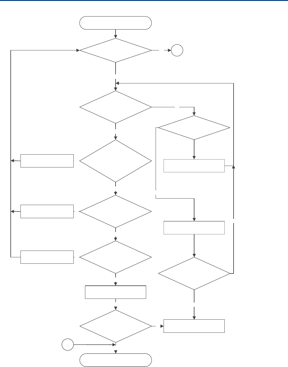
Chapter 11: Troubleshooting Power-up troubleshooting
Page 11-35
Power-up troubleshooting
Module does not power ON
Is the
LED always red?
Is there AC power
going to the supply?
No
Switch ON AC mains power
Test cable, use known
good cable. Could the radio be
in default mode
Yes
Yes
Test cable?
No
Is cable length < 300 meters?
Yes
Connect to a known power
supply
Is the module’s
red L ED ON ?
Yes
Yes
Module is powered ON
Yes
Ethernet cable
repa ire d
Contact Cambium Support for
RMA
No
Is Module’s power
LED ON?
No
A
Yes
Cable wire and pin out
corrected
Cable length within
300 meters
Yes
No
No
A
Connect to known good
module
Is module getting
powered ON?
No
Yes

Chapter 11: Troubleshooting Registration and connectivity troubleshooting
Page 11-36
Registration and connectivity troubleshooting
SM/BMS Registration
If no SMs are registered to this AP, then the Session Status tab displays the simple message
No
sessions
. In this case, try the following steps.
1 More finely aim the SM or SMs toward the AP.
2 Recheck the Session Status tab of the AP for the presence of LUIDs.
3 If still no LUIDs are reported on the Session Status tab, click the
Configuration
button on the left side of the
Home
page.
RESULT:
The AP responds by opening the AP Configuration page.
4 Click the Radio tab.
5 Find the
Color Code
parameter and note the setting.
6 In the same sequence as you did for the AP directly under
Configuring Link for Test
on Page 5-15, connect the SM to a computing device and to power.
7 On the left side of the SM Home page, click the
Configuration
button.
RESULT:
The Configuration page of the SM opens.
8 Click the Radio tab.
9 If the transmit frequency of the AP is not selected in the
Custom Radio Frequency
Scan Selection List
parameter, select the frequency that matches.
10 If the
Color Code
parameter on this page is not identical to the
Color Code
parameter you noted from the AP, change one of them so that they match.
11 At the bottom of the Radio tab for the SM, click the
Save Changes
button.
12 Click the
Reboot
button.
13 Allow several minutes for the SM to reboot and register to the AP.
14 Return to the computing device that is connected to the AP.
15 Recheck the Session Status tab of the AP for the presence of LUIDs.

Page I
Glossary
Term
Definition
10Base-T Technology in Ethernet communications that can deliver 10 Mb of
data across 328 feet (100 meters) of CAT 5 cable.
169.254.0.0 Gateway IP address default in Cambium fixed wireless broadband IP
network modules.
169.254.1.1 IP address default in Cambium fixed wireless broadband IP network
modules.
255.255.0.0 Subnet mask default in Cambium fixed wireless broadband IP
network modules and in Microsoft and Apple operating systems.
802.3 An IEEE standard that defines the contents of frames that are
transferred through Ethernet connections. Each of these frames
contains a preamble, the address to which the frame is sent, the
address that sends the frame, the length of the data to expect, the
data, and a checksum to validate that no contents were lost.
Access Point Cluster Two to six Access Point Modules that together distribute network or
Internet services to a community of subscribers. Each Access Point
Module covers a 60° or 90° sector. This cluster covers as much as
360°. Also known as AP cluster.
Access Point Module Also known as AP. One module that distributes network or Internet
services in a 60° or 90° sector.
ACT/4 Second-from-left LED in the module. In the operating mode, this
LED is lit when data activity is present on the Ethernet link.
Address Resolution
Protocol
Protocol defined in RFC 826 to allow a network element to correlate
a host IP address to the Ethernet address of the host. See
http://www.faqs.org/rfcs/rfc826.html.
Aggregate Throughput The sum of the throughputs in the uplink and the downlink.
AP Access Point Module. One module that distributes network or
Internet services to subscriber modules.
ARP Address Resolution Protocol. A protocol defined in RFC 826 to allow
a network element to correlate a host IP address to the Ethernet
address of the host. See http://www.faqs.org/rfcs/rfc826.html.
APs MIB
Management Information Base file that defines objects that are
specific to the Access Point Module. See also Management

Chapter 11: Troubleshooting Registration and connectivity troubleshooting
Page II
Term
Definition
Information Base.
ASN.1 Abstract Syntax Notation One language. The format of the text files
that compose the Management Information Base.
Attenuation Reduction of signal strength caused by the travel from the
transmitter to the receiver, and caused by any object between. In
the absence of objects between, a signal that has a short
wavelength experiences a high degree of attenuation nevertheless.
BER Bit Error Rate. The ratio of incorrect data received to correct data
received.
Bit Error Rate Ratio of incorrect data received to correct data received.
Box MIB Management Information Base file that defines module-level
objects. See also Management Information Base.
Bridge Network element that uses the physical address (not the logical
address) of another to pass data. The bridge passes the data to
either the destination address, if found in the simple routing table,
or to all network segments other than the one that transmitted the
data. Modules are Layer 2 bridges except that, where NAT is
enabled for an SM, the SM is a Layer 3 switch. Compare to Switch
and Router, and see also NAT.
Buckets Theoretical data repositories that can be filled at preset rates or
emptied when preset conditions are experienced, such as when
data is transferred.
Burst Preset amount limit of data that may be continuously transferred.
CAT 5 Cable Cable that delivers Ethernet communications from module to
module. Later modules auto-sense whether this cable is wired in a
straight-through or crossover scheme.
CIR Committed Information Rate. For an SM or specified group of SMs,
a level of bandwidth that can be guaranteed to never fall below a
specified minimum (unless oversubscribed). In the Cambium
implementation, this is controlled by the Low Priority Uplink CIR,
Low Priority Downlink CIR, High Priority Uplink CIR, and High
Priority Downlink CIR parameters.
Cluster Management
Module
Module that provides power, GPS timing, and networking
connections for an AP cluster. Also known as CMM4.
CMM Cluster Management Module. A module that provides power, GPS
timing, and networking connections for an Access Point cluster.
CodePoint See DiffServ.
Color Code Field Module parameter that identifies the other modules with which

Chapter 11: Troubleshooting Registration and connectivity troubleshooting
Page III
Term
Definition
communication is allowed. The range of valid values is 0 to 255.
Community String Field Control string that allows a network management station to access
MIB information about the module.
Country Code A parameter that offers multiple fixed selections, each of which
automatically implements frequency band range restrictions for the
selected country. Units shipped to countries other than the United
States must be configured with the corresponding Region Code and
Country Code to comply with local regulatory requirements.
CRCError Field This field displays how many CRC errors occurred on the Ethernet
controller.
Data Encryption Standard Over-the-air link option that uses secret 56-bit keys and 8 parity bits.
Data Encryption Standard (DES) performs a series of bit
permutations, substitutions, and recombination operations on
blocks of data.
Demilitarized Zone Internet Protocol area outside of a firewall. Defined in RFC 2647. See
http://www.faqs.org/rfcs/rfc2647.html.
DES Data Encryption Standard. An over-the-air link option that uses
secret 56-bit keys and 8 parity bits. DES performs a series of bit
permutations, substitutions, and recombination operations on
blocks of data.
DFS See Dynamic Frequency Selection
DHCP Dynamic Host Configuration Protocol, defined in RFC 2131. Protocol
that enables a device to be assigned a new IP address and TCP/IP
parameters, including a default gateway, whenever the device
reboots. Thus DHCP reduces configuration time, conserves IP
addresses, and allows modules to be moved to a different network
within the system. See http://www.faqs.org/rfcs/rfc2131.html. See
also Static IP Address Assignment.
DiffServ Differentiated Services, consistent with RFC 2474. A byte in the type
of service (TOS) field of packets whose values correlates to the
channel on which the packet should be sent. The value is a numeric
code point. Cambium modules map each of 64 code points to
values of 0 through 7. Three of these code points have fixed values,
and the remaining 61 are settable. Values of 0 through 3 map to the
low-priority channel; 4 through 7 to the high-priority channel. The
mappings are the same as 802.1p VLAN priorities. (However,
configuring DiffServ does not automatically enable the VLAN
feature.) Among the settable parameters, the values are set in the
AP for all downlinks within the sector and in the SM for each uplink.

Chapter 11: Troubleshooting Registration and connectivity troubleshooting
Page IV
Term
Definition
DMZ Demilitarized Zone as defined in RFC 2647. An Internet Protocol area
outside of a firewall. See http://www.faqs.org/rfcs/rfc2647.html.
Dynamic Frequency
Selection
A requirement in certain countries and regions for systems to detect
interference from other systems, notably radar systems, and to
avoid co-channel operation with these systems.
Dynamic Host
Configuration Protocol
See DHCP.
Electronic Serial Number Hardware address that the factory assigns to the module for
identification in the Data Link layer interface of the Open Systems
Interconnection system. This address serves as an electronic serial
number. Same as MAC Address.
ESN Electronic Serial Number. The hardware address that the factory
assigns to the module for identification in the Data Link layer
interface of the Open Systems Interconnection system. This address
serves as an electronic serial number. Same as MAC Address.
Ethernet Protocol Any of several IEEE standards that define the contents of frames
that are transferred from one network element to another through
Ethernet connections.
ETSI European Telecommunications Standards Institute
Fade Margin The difference between strength of the received signal and the
strength that the receiver requires for maintaining a reliable link. A
higher fade margin is characteristic of a more reliable link. Standard
operating margin.
FCC Federal Communications Commission of the U.S.A.
Field-programmable Gate
Array
Array of logic, relational data, and wiring data that is factory
programmed and can be reprogrammed.
File Transfer Protocol Utility that transfers of files through TCP (Transport Control
Protocol) between computing devices that do not operate on the
same platform. Defined in RFC 959. See
http://www.faqs.org/rfcs/rfc959.html.
FPGA Field-programmable Gate Array. An array of logic, relational data,
and wiring data that is factory programmed and can be
reprogrammed.
Free Space Path Loss Signal attenuation that is naturally caused by atmospheric
conditions and by the distance between the antenna and the
receiver.
Fresnel Zone Space in which no object should exist that can attenuate, diffract, or
reflect a transmitted signal before the signal reaches the target

Chapter 11: Troubleshooting Registration and connectivity troubleshooting
Page V
Term
Definition
receiver.
FTP File Transfer Protocol, defined in RFC 959. Utility that transfers of
files through TCP (Transport Control Protocol) between computing
devices that do not operate on the same platform. See
http://www.faqs.org/rfcs/rfc959.html.
Global Positioning
System
Network of satellites that provides absolute time to networks on
earth, which use the time signal to synchronize transmission and
reception cycles (to avoid interference) and to provide reference for
troubleshooting activities.
GPS Global Positioning System. A network of satellites that provides
absolute time to networks on earth, which use the time signal to
synchronize transmission and reception cycles (to avoid
interference) and to provide reference for troubleshooting activities.
GPS/3 Third-from-left LED in the module. In the operating mode for an
Access Point Module, this LED is continuously lit as the module
receives sync pulse. In the operating mode for a Subscriber, this
LED flashes on and off to indicate that the module is not registered.
GUI Graphical user interface.
High-priority Channel Channel that supports low-latency traffic (such as Voice over IP)
over low-latency traffic (such as standard web traffic and file
downloads). To recognize the latency tolerance of traffic, this
channel reads the IPv4 Type of Service DiffServ Control Point
(DSCP) bits. Enabling the high-priority channel reduces the
maximum number of SMs that can be served in the sector.
HTTP Hypertext Transfer Protocol, used to make the Internet resources
available on the World Wide Web. Defined in RFC 2068. See
http://www.faqs.org/rfcs/rfc2068.html.
HTTPS Hypertext Transfer Protocol Secure (HTTPS)
ICMP Internet Control Message Protocols defined in RFC 792, used to
identify Internet Protocol (IP)-level problems and to allow IP links to
be tested. See http://www.faqs.org/rfcs/rfc792.html.
IP Internet Protocol defined in RFC 791. The Network Layer in the
TCP/IP protocol stack. This protocol is applied to addressing,
routing, and delivering, and re-assembling data packets into the
Data Link layer of the protocol stack. See
http://www.faqs.org/rfcs/rfc791.html.
IP Address 32-bit binary number that identifies a network element by both
network and host. See also Subnet Mask.

Chapter 11: Troubleshooting Registration and connectivity troubleshooting
Page VI
Term
Definition
IPv4 Traditional version of Internet Protocol, which defines 32-bit fields
for data transmission.
ISM Industrial, Scientific, and Medical Equipment radio frequency band,
in the 900-MHz, 2.4-GHz, and 5.8-GHz ranges.
L2TP over IPSec Level 2 Tunneling Protocol over IP Security. One of several virtual
private network (VPN) implementation schemes. Regardless of
whether Subscriber Modules have the Network Address Translation
feature (NAT) enabled, they support VPNs that are based on this
protocol.
Late Collision Field This field displays how many late collisions occurred on the
Ethernet controller. A normal collision occurs during the first 512
bits of the frame transmission. A collision that occurs after the first
512 bits is considered a late collision. A late collision is a serious
network problem because the frame being transmitted is discarded.
A late collision is most commonly caused by a mismatch between
duplex configurations at the ends of a link segment.
Line of Sight Wireless path (not simply visual path) direct from module to
module. The path that results provides both ideal aim and an ideal
Fresnel zone.
LNK/5 Furthest left LED in the module. In the operating mode, this LED is
continuously lit when the Ethernet link is present. In the aiming
mode for a Subscriber Module, this LED is part of a bar graph that
indicates the quality of the RF link.
Logical Unit ID Final octet of the 4-octet IP address of the module.
LOS Line of sight. The wireless path (not simply visual path) direct from
module to module. The path that results provides both ideal aim
and an ideal Fresnel zone.
LUID Logical Unit ID. The final octet of the 4-octet IP address of the
module.
MAC Address Media Access Control address. The hardware address that the
factory assigns to the module for identification in the Data Link layer
interface of the Open Systems Interconnection system. This address
serves as an electronic serial number.
Management Information
Base
Space that allows a program (agent) in the network to relay
information to a network monitor about the status of defined
variables (objects).
Maximum Information
Rate (MIR)
The cap applied to the bandwidth of an SM or specified group of
SMs. In the Cambium implementation, this is controlled by the
Sustained Uplink Data Rate, Uplink Burst Allocation, Sustained

Chapter 11: Troubleshooting Registration and connectivity troubleshooting
Page VII
Term
Definition
Downlink Data Rate, and Downlink Burst Allocation parameters.
MIB Management Information Base. Space that allows a program
(agent) in the network to relay information to a network monitor
about the status of defined variables (objects).
MIR See Maximum Information Rate.
NAT Network Address Translation defined in RFC 1631. A scheme that
isolates Subscriber Modules from the Internet. See
http://www.faqs.org/rfcs/rfc1631.html.
NEC National Electrical Code. The set of national wiring standards that
are enforced in the U.S.A.
NetBIOS Protocol defined in RFC 1001 and RFC 1002 to support an
applications programming interface in TCP/IP. This interface allows
a computer to transmit and receive data with another host computer
on the network. RFC 1001 defines the concepts and methods. RFC
1002 defines the detailed specifications. See
http://www.faqs.org/rfcs/rfc1001.html and
http://www.faqs.org/rfcs/rfc1002.html.
Network Address
Translation
Scheme that defines the Access Point Module as a proxy server to
isolate registered Subscriber Modules from the Internet. Defined in
RFC 1631. See http://www.faqs.org/rfcs/rfc1631.html.
Network Management
Station
See NMS.
NMS Network Management Station. A monitor device that uses Simple
Network Management Protocol (SNMP) to control, gather, and
report information about predefined network variables (objects).
See also Simple Network Management Protocol.
Default Mode Device that enables the operator to regain control of a module that
has been locked by the No Remote Access feature, the 802.3 Link
Disable feature, or a password or IP address that cannot be recalled.
This device can be either fabricated on site or ordered.
PMP See Point-to-Multipoint Protocol.
Point-to-Multipoint
Protocol
Defined in RFC 2178, which specifies that data that originates from a
central network element can be received by all other network
elements, but data that originates from a non-central network
element can be received by only the central network element. See
http://www.faqs.org/rfcs/rfc2178.html. Also referenced as PMP.
PPPoE Point to Point Protocol over Ethernet. Supported on SMs for
operators who use PPPoE in other parts of their network operators

Chapter 11: Troubleshooting Registration and connectivity troubleshooting
Page VIII
Term
Definition
who want to deploy PPPoE to realize per-subscriber authentication,
metrics, and usage control.
PPS Packet Per Second
PPTP Point to Point Tunneling Protocol. One of several virtual private
network implementations. Regardless of whether the Network
Address Translation (NAT) feature enabled, Subscriber Modules
support VPNs that are based on this protocol.
Protective Earth Connection to earth (which has a charge of 0 volts). Also known as
ground.
Proxy Server Network computer that isolates another from the Internet. The
proxy server communicates for the other computer, and sends
replies to only the appropriate computer, which has an IP address
that is not unique or not registered.
Radio Signal Strength
Indicator
Relative measure of the strength of a received signal. An acceptable
link displays a Radio Signal Strength Indicator (RSSI) value of
greater than 700.
Reflection Change of direction and reduction of amplitude of a signal that
encounters an object larger than the wavelength. Reflection may
cause an additional copy of the wavelength to arrive after the
original, unobstructed wavelength arrives. This causes partial
cancellation of the signal and may render the link unacceptable.
However, in some instances where the direct signal cannot be
received, the reflected copy may be received and render an
otherwise unacceptable link acceptable.
Region Code A parameter that offers multiple fixed selections, each of which
automatically implements frequency band range restrictions for the
selected region. Units shipped to regions other than the United
States must be configured with the corresponding Region Code to
comply with local regulatory requirements.
RF Radio frequency. How many times each second a cycle in the
antenna occurs, from positive to negative and back to positive
amplitude.
RJ-12 Standard cable that is typically used for telephone line or modem
connection.
RJ-45 Standard cable that is typically used for Ethernet connection. This
cable may be wired as straight-through or as crossover. Later
modules auto-sense whether the cable is straight-through or
crossover.
Router Network element that uses the logical (IP) address of another to

Chapter 11: Troubleshooting Registration and connectivity troubleshooting
Page IX
Term
Definition
pass data to only the intended recipient. Compare to Switch and
Bridge.
RSSI Radio Signal Strength Indicator. A relative measure of the strength
of a received signal. An acceptable link displays an RSSI value of
greater than 700.
Self-interference Interference with a module from another module in the same
network.
Simple Network
Management Protocol
Standard that is used for communications between a program
(agent) in the network and a network management station
(monitor). Defined in RFC 1157. See
http://www.faqs.org/rfcs/rfc1157.html.
SM Customer premises equipment (CPE) device that extends network or
Internet services by communication with an Access Point Module or
an Access Point cluster.
SNMP See Simple Network Management Protocol, defined in RFC 1157.
SNMPv3 SNMP version 3
SNMP Trap Capture of information that informs the network monitor through
Simple Network Management Protocol of a monitored occurrence in
the module.
Static IP Address
Assignment
Assignment of Internet Protocol address that can be changed only
manually. Thus static IP address assignment requires more
configuration time and consumes more of the available IP
addresses than DHCP address assignment does. RFC 2050 provides
guidelines for the static allocation of IP addresses. See
http://www.faqs.org/rfcs/rfc2050.html. See also DHCP.
Subnet Mask 32-bit binary number that filters an IP address to reveal what part
identifies the network and what part identifies the host. The number
of subnet mask bits that are set to 1 indicates how many leading
bits of the IP address identify the network. The number of subnet
mask bits that are set 0 indicate how many trailing bits of the IP
address identify the host.
Subscriber Module Customer premises equipment (CPE) device that extends network or
Internet services by communication with an Access Point Module or
an Access Point cluster.
Sustained Data Rate Preset rate limit of data transfer.
Switch Network element that uses the port that is associated with the
physical address of another to pass data to only the intended
recipient. Compare to Bridge and Router.

Chapter 11: Troubleshooting Registration and connectivity troubleshooting
Page X
Term
Definition
Sync GPS (Global Positioning System) absolute time, which is passed
from one module to another. Sync enables timing that prevents
modules from transmitting or receiving interference. Sync also
provides correlative time stamps for troubleshooting efforts.
TCP Alternatively known as Transmission Control Protocol or Transport
Control Protocol. The Transport Layer in the TCP/IP protocol stack.
This protocol is applied to assure that data packets arrive at the
target network element and to control the flow of data through the
Internet. Defined in RFC 793. See
http://www.faqs.org/rfcs/rfc793.html.
TDD Time Division Duplexing. Synchronized data transmission with
some time slots allocated to devices transmitting on the uplink and
some to the device transmitting on the downlink.
telnet Utility that allows a client computer to update a server. A firewall
can prevent the use of the telnet utility to breach the security of the
server. See http://www.faqs.org/rfcs/rfc818.html,
http://www.faqs.org/rfcs/rfc854.html and
http://www.faqs.org/rfcs/rfc855.html.
Tokens Theoretical amounts of data. See also Buckets.
TxUnderrun Field This field displays how many transmission-underrun errors
occurred on the Ethernet controller.
UDP User Datagram Protocol. A set of Network, Transport, and Session
Layer protocols that RFC 768 defines. These protocols include
checksum and address information but does not retransmit data or
process any errors. See http://www.faqs.org/rfcs/rfc768.html.
udp User-defined type of port.
U-NII Unlicensed National Information Infrastructure radio frequency
band, in the 5.1GHz through 5.8 GHz ranges.
VID VLAN identifier. See also VLAN.
VLAN Virtual local area network. An association of devices through
software that contains broadcast traffic, as routers would, but in the
switch-level protocol.
VPN Virtual private network for communication over a public network.
One typical use is to connect remote employees, who are at home
or in a different city, to their corporate network over the Internet.
Any of several VPN implementation schemes is possible. SMs
support L2TP over IPSec (Level 2 Tunneling Protocol over IP
Security) VPNs and PPTP (Point to Point Tunneling Protocol) VPNs,
regardless of whether the Network Address Translation (NAT)

Chapter 11: Troubleshooting Registration and connectivity troubleshooting
Page XI
Term
Definition
feature enabled.