Cambium Networks 50450I Fixed Outdoor Point to Multipoint Transceiver User Manual 450 Platform User Guide
Cambium Networks Limited Fixed Outdoor Point to Multipoint Transceiver 450 Platform User Guide
Contents
- 1. Installation Guide
- 2. User Guide Part 1
- 3. User Guide Part 2
- 4. User Guide Part 3
- 5. User Guide Part 4
- 6. User Guide Part 5
- 7. User Guide Part 6
- 8. User Guide Part 7
- 9. Exhibit D Users Manual per 2 1033 b3
- 10. User Manual - Part 1
- 11. User Manual - Part 2
- 12. User Manual - Part 3
- 13. User Manual - Part 4
- 14. Users Manual - Part 5
- 15. Users Manual - Part 6
- 16. User Manual
User Manual - Part 3
Chapter 6: Installation Installing external antennas to a connectorized ODU
Page 6-31
PMP 450 Series
Assembling the PMP 450 AP antenna
To assemble a PMP 450 Series AP antenna, perform the following steps.
Note
Cambium recommends to assemble the antenna, attach the AP and cabling, and to
seal the RF connections before installing the unit at the deployment site.
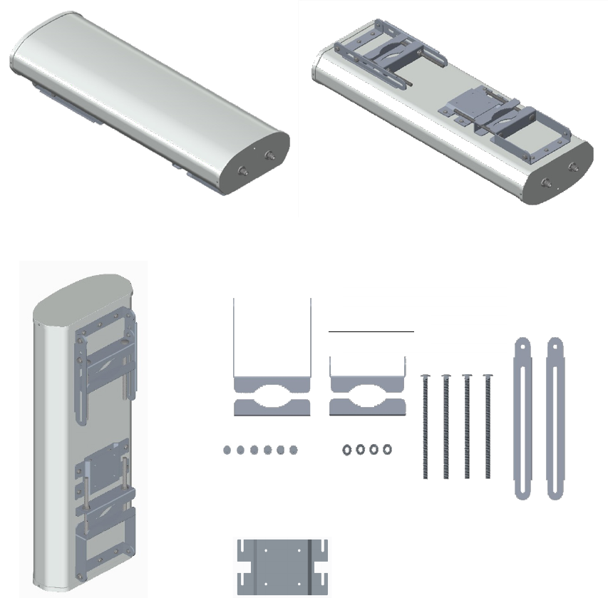
1
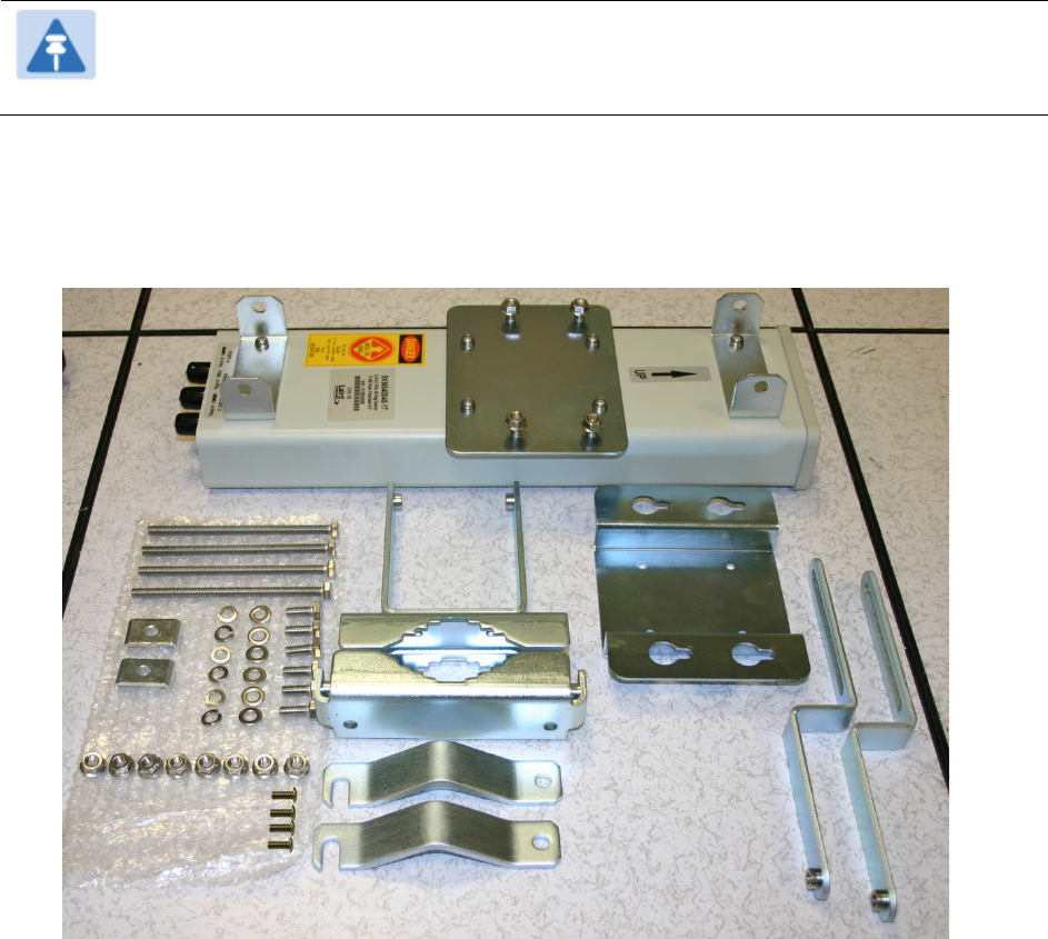
Inventory the parts to ensure that you have them all before you begin. The full set of parts
is shown below.
Figure 92
PMP 450 AP antenna parts
Chapter 6: Installation Installing external antennas to a connectorized ODU
Page 6-32
2
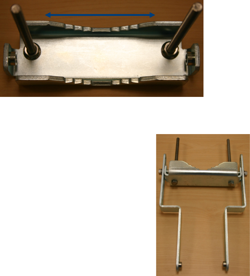
Begin assembling the upper bracket by attaching the (2) 7” hex bolts to the bracket using
(2) serrated flange nuts
Figure 93
AP antenna upper bracket assembly
3
Attach the upper bracket to the adjustment
arms using (2) hex bolts, (2) flat washers
and (2) lock washers. Feed the bolt through
the lock washer then flat washer, then
thread the bolt into the upper bracket’s
threaded receptacle.
Figure 94
AP antenna upper bracket
attached to upper adjustment
arms
Chapter 6: Installation Installing external antennas to a connectorized ODU
Page 6-33
4
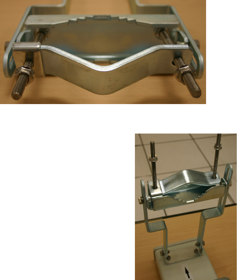
Attach the rear strap to the upper bracket using (2) serrated flange nuts and (1) retaining
bracket. Do not tighten the nuts now.
Figure 95
Rear strap connected to upper AP antenna bracket
5
Attach the entire upper bracket to the
antenna using (2) hex bolts, (2) flat washers
and (2) lock washers. Feed the bolt through
the lock washer then flat washer, then
thread the bolt into the upper bracket’s
threaded receptacle.
Figure 96
Assembled upper bracket
connected to AP antenna
Chapter 6: Installation Installing external antennas to a connectorized ODU
Page 6-34
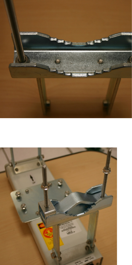
6
Begin assembling the lower bracket by
attaching the (2) 7” hex bolts to the bracket
using (2) serrated flange nuts
Figure 97
AP Antenna Lower Bracket
Assembly
7
Attach the rear strap to the bracket using (2)
serrated flange nuts and (1) retaining
bracket. Do not tighten the nuts now.
Attach the entire lower bracket to the
antenna using (2) hex bolts, (2) flat washers
and (2) lock washers.
Figure 98
Lower bracket attached to AP
antenna
Attaching the PMP 450 AP to the antenna
To attach a PMP 450 Series AP to the antenna, perform the following steps.
Chapter 6: Installation Installing external antennas to a connectorized ODU
Page 6-35
Note
Use shielded cable for all infrastructure connections associated with APs, SMs, and
CMMs. The environment that these modules operate in often has significant unknown
or varying RF energy. Operator experience consistently indicates that the additional
cost of shielded cables is more than compensated by predictable operation and
reduced costs for troubleshooting and support.
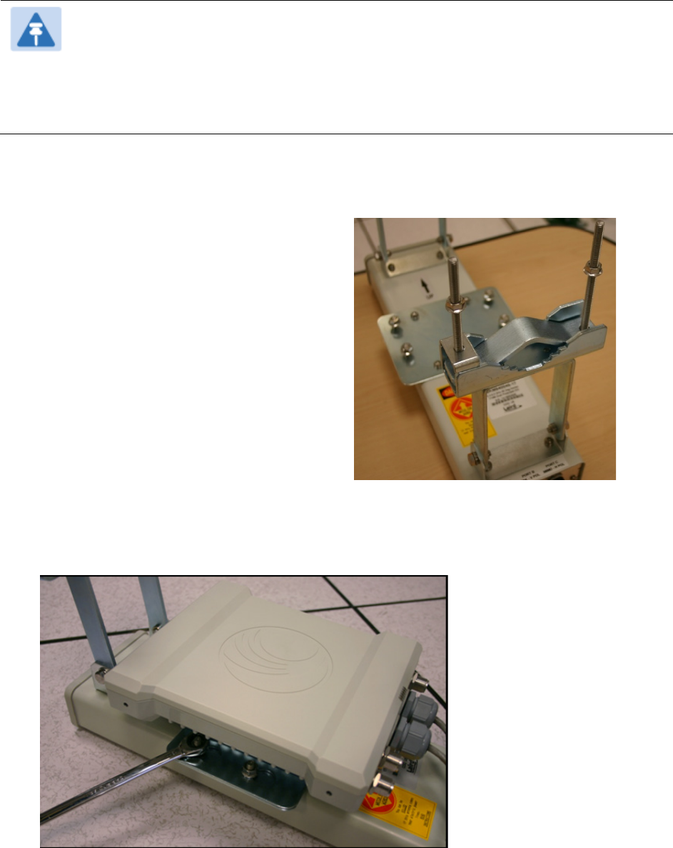
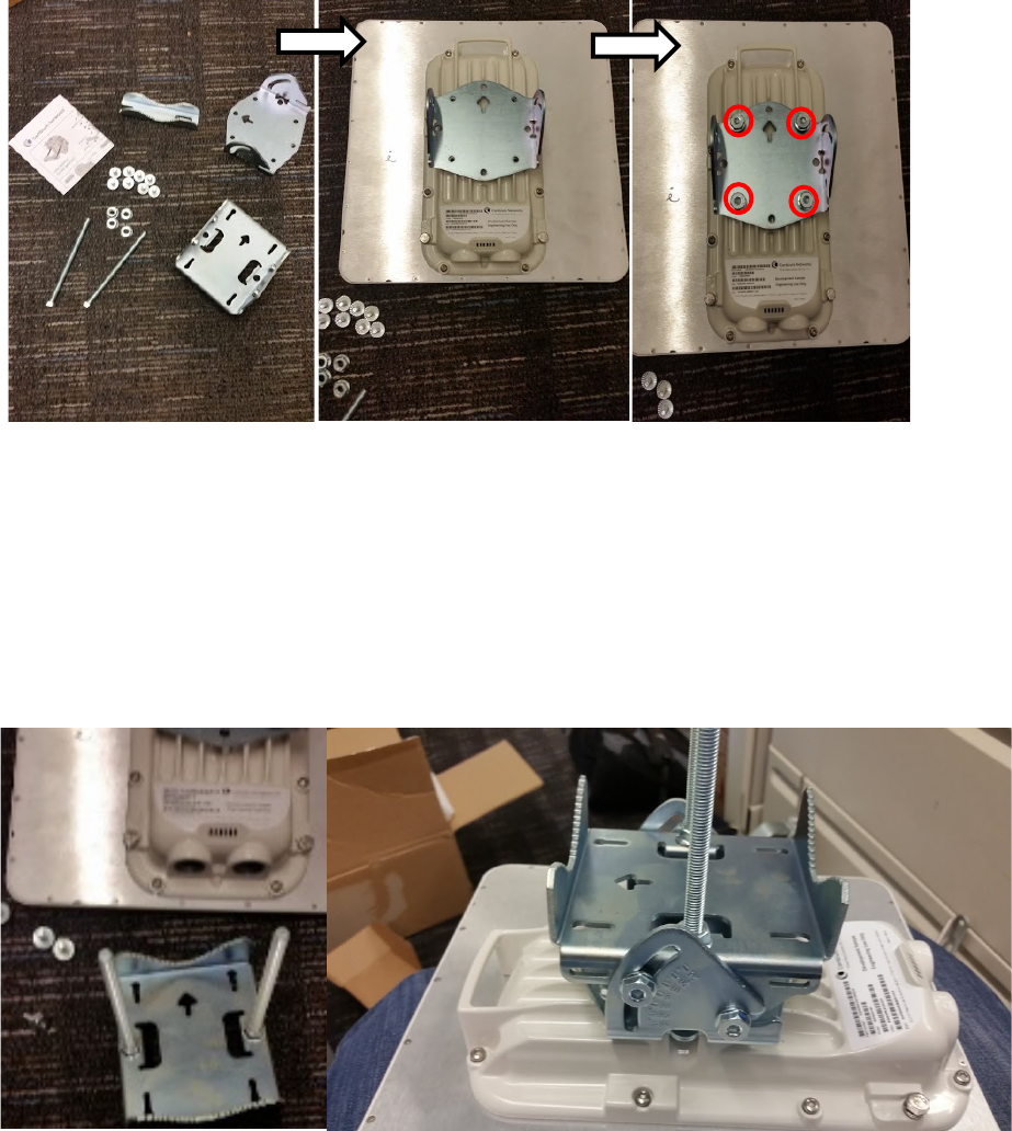
1
Attach the included bracket to the rear of
the AP using the (4) M5 x 7mm bolts
Figure 99
Attaching bracket to the rear of
the AP
2
Attach the AP to the antenna by sliding the bracket onto the bolts and tighten the (4)
serrated flange nuts using a 13 mm spanner wrench.
Figure 100
Lower bracket attached to AP antenna
Chapter 6: Installation Installing external antennas to a connectorized ODU
Page 6-36
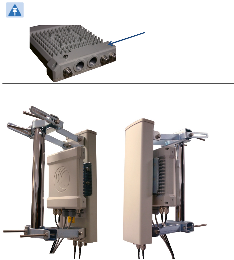
Note
If using a non-standard antenna, do not cover the equilibrium membrane vent located
on the back of the unit.
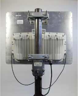
Figure 101 Mounted PMP 450 AP and antenna assembly, viewed from back and back
Equilibrium Membrane Vent
Chapter 6: Installation Installing external antennas to a connectorized ODU
Page 6-37
Attaching the PMP 450 Series AP and antenna to the mount point
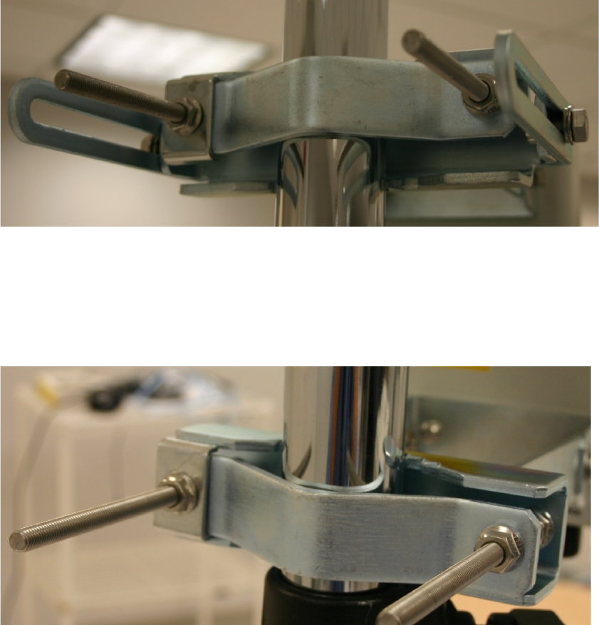
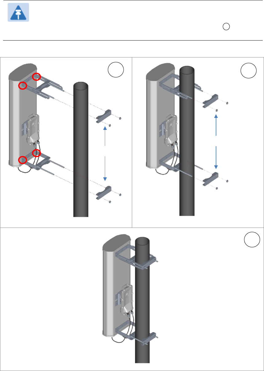
1
Attach the upper bracket of the antenna to the mount point by closing the rear strap around
the pole and tightening the (2) serrated flange nuts using a 13mm spanner wrench. These
must be tightened evenly on the pol to avoid jumping/stripping threads.
Figure 102
Attaching the AP antenna upper bracket to the pole
2
Attach the lower bracket of the antenna to the mount point by closing the rear strap around
the pole and tightening the (2) serrated flange nuts using a 13mm spanner wrench. These
must be tightened evenly on the pole to avoid jumping/stripping threads.
Figure 103
Attaching the AP antenna lower bracket to the pole
3
Use a local map, compass, and/or GPS device as needed to determine the direction that one
or more APs require to each cover the 90
°
sector.

Chapter 6: Installation Installing external antennas to a connectorized ODU
Page 6-38
4
Choose the best mounting location for your particular application.
Note
Use the embedded spectrum analyzer or a commercial analyzer to evaluate
the frequencies present in various locations. OFDM APs need not be mounted
next to each other. They can be distributed throughout a given site. However,
the 90° offset must be maintained. If you want to collocate these APs with
PMP 100 Series APs of the 5.4-GHz frequency band range, plan to allow at
least 25 MHz of separation between their center channels.
5
Secure a ground strap to the ground lug on the back of the AP.
6
Secure the ground strap to the pole, tower, or other trusted ground.
7
The bracket of the standard antenna has provision for measured down tilt. The
recommended practice is to use one of the many radio analysis and mapping tools or on-
line tools to calculate down tilt based on antenna height above the service area.
The proper angle of tilt can be calculated as a factor of both the difference in elevation and
the distance that the link spans. Even in this case, a plumb line and a protractor can be
helpful to ensure the proper tilt. This tilt is typically minimal.
The number of degrees to offset (from vertical) the mounting hardware leg of the support
tube is equal to the angle of elevation from the lower module to the higher module (<B in
the example provided in Figure 67).

Chapter 6: Installation Installing external antennas to a connectorized ODU
Page 6-39
Figure 104 Variables for calculating angle of elevation (and depression)
Where:
Is:
b angle of elevation
B vertical difference in elevation
A horizontal distance between modules
To use metric units to find the angle of elevation, use the following formula:
Where:
Is:
B expressed in meters
A expressed in kilometers
To use English standard units to find the angle of elevation, use the following formula:
Where:
Is:
B expressed in feet
A expressed in miles
The angle of depression from the higher module is identical to the angle of elevation from
the lower module.
8
Connect the coax cables to the antenna and to the AP
9
Weatherproof the connector on the coax cables (see section Attaching and weatherproofing
an N type connector on page 6-69).
tan b =
B
1000A
tan b =
B
5280A
Chapter 6: Installation Installing external antennas to a connectorized ODU
Page 6-40
PMP 450i Series AP 900 MHz
Mounting of PMP 450i AP 900 MHz
1
Inventory the parts to ensure that you have them all before you begin. The full set of parts
is shown in Figure 106.
Figure 105
PMP 450i AP 900 MHz antenna unbox view
Figure 106
PMP 450i AP 900 MHz antenna inventory
Upper bracket
Lower bracket
Adjustable arm
Nuts and bolts
Radio assembly plate
Chapter 6: Installation Installing external antennas to a connectorized ODU
Page 6-41
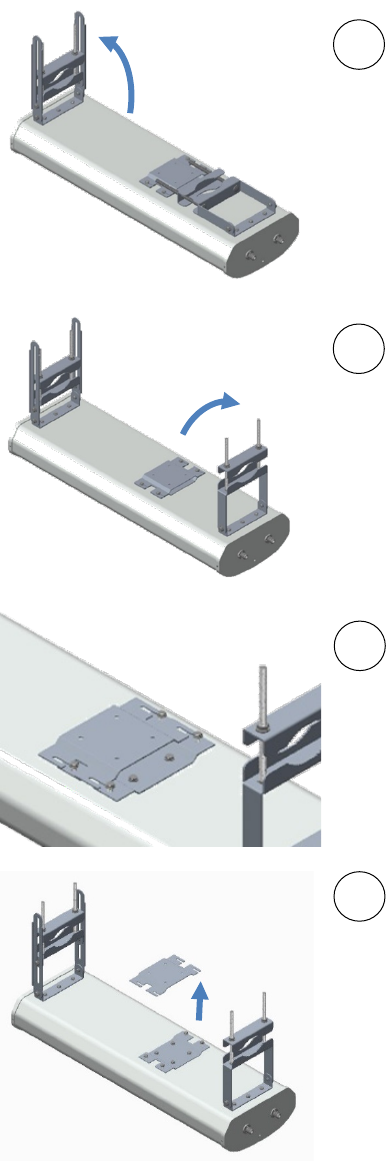
2
(1) Unfold the upper bracket assembly of the
antenna.
(2) Unfold the lower bracket assembly.
(3) Loose the radio assembly plate by
untightening M8 four bolds.
(4) Remove the radio assembly top plate by
sliding towards upper bracket assembly.
1
2
4
3
Chapter 6: Installation Installing external antennas to a connectorized ODU
Page 6-42
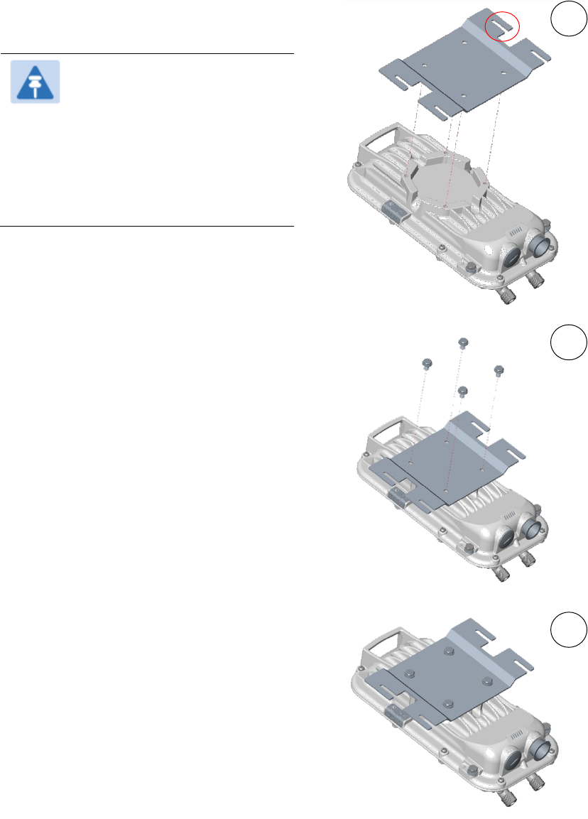
3
(1) Place the radio assembly plate on the
radio and align holes with radio enclosure.
Note
Ensure that the radio plate
notch opening and RF port of
radio in same direction. It is
also important to make sure
you attach the radio assembly
plate in the proper orientation
as shown in figure.
(2) Insert M6 bolts through plate into radio
enclosure
(3) Fix the plate by tightening four bolts
with a torque setting on 2 ±0.5 Nm
1
2
3
Chapter 6: Installation Installing external antennas to a connectorized ODU
Page 6-43
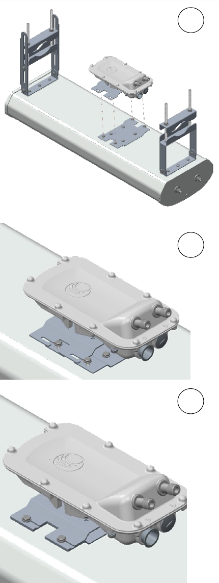
4
(1) Place the radio mounted plate on sector
antenna as shown in the figure. Ensure that
the orientation of RF port of antenna and
radio are in same direction
(2) Line up the radio assembly to four bolts
and slide towards lower bracket assembly
to lock.
(3) Tighten the radio assembly plate using
four M8 bolts to a torque setting of 2 ±0.5
Nm
1
3
2
Chapter 6: Installation Installing external antennas to a connectorized ODU
Page 6-44
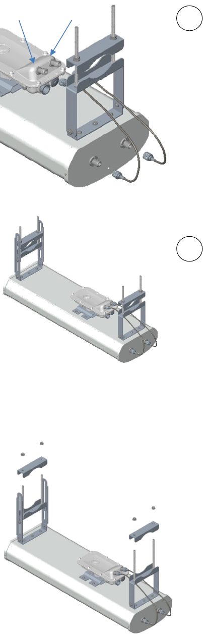
5
(1) Connect the port A of AP to vertical and
port B of AP to horizontal polarization
interfaces of the antenna with RF cable.
Ensure that the RF cables are pass-through
inside the lower bracket assembly
(2) Hand tighten the N type connectors and
the torque should not exceed more than 1
Nm
Mounting of PMP 450i AP 900 MHz antenna to the pole
The mounting procedure of PMP 450i AP 900 MHz and antenna to the pole is given below:
1
Remove the upper and lower rear bracket
strap from the sector antenna.
1
2
Port A
Port B
Chapter 6: Installation Installing external antennas to a connectorized ODU
Page 6-45
2
Attach the upper and lower bracket of the antenna to the mount point by closing the rear
strap around the pole.
Note
Before mounting the radio on the pole, secure the upper and lower bracket
assemblies with a torque setting of 3 to 4 Nm as shown in Figure 1 . Also,
ensure that inner strap of upper bracket is set to zero degree marking.
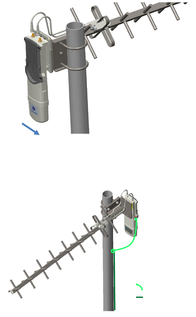
Figure 107
Attaching radio mounting PMP 450i AP 900 MHz antenna to the pole
1
2
3
Rear strap
Rear strap
Inner strap
Chapter 6: Installation Installing external antennas to a connectorized ODU
Page 6-46
3
Tighten the four serrated flange M10 nuts
on the upper and lower rear straps using a
17 mm spanner wrench. These must be
tightened evenly on the pole to avoid
jumping/stripping threads
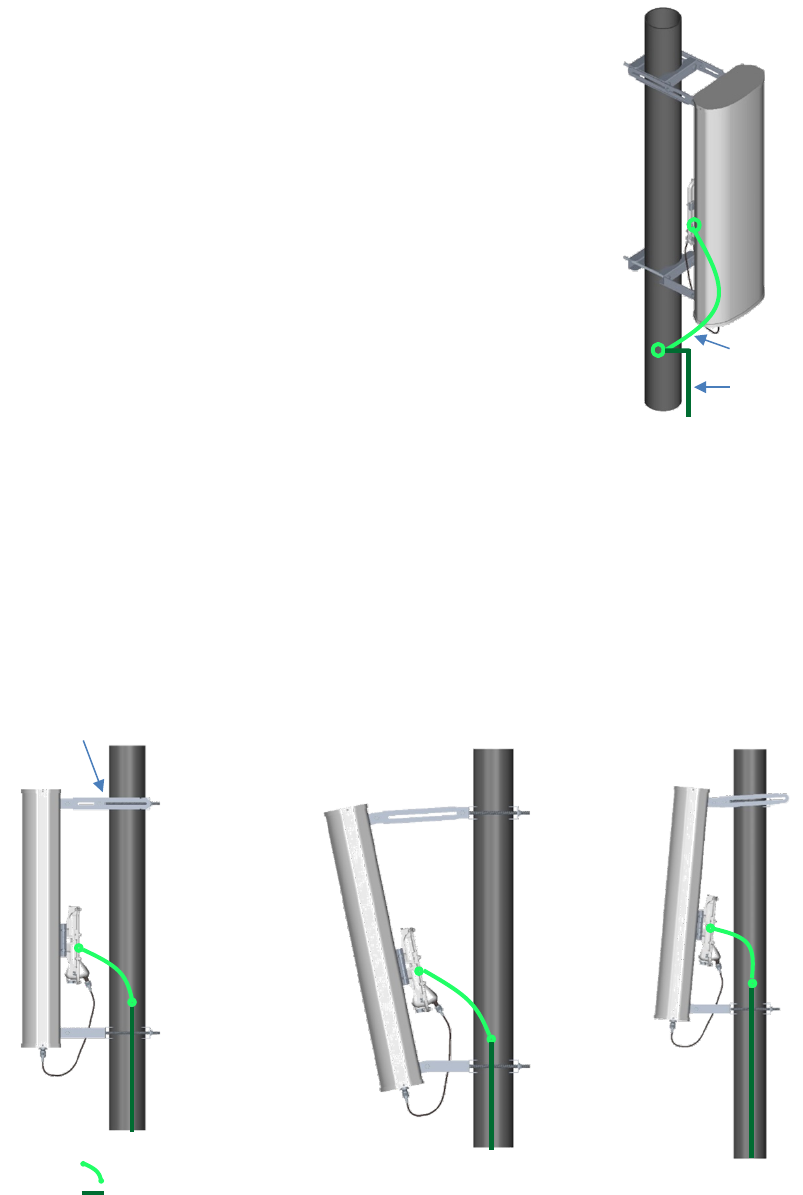
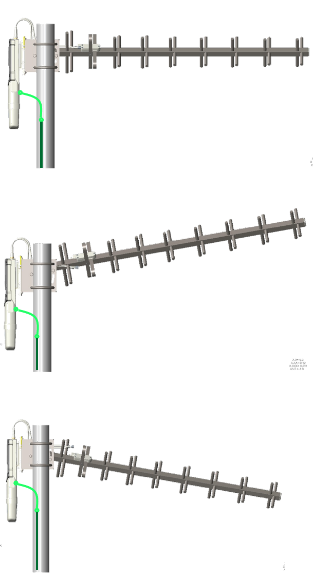
Sector antenna alignment
The 900 MHz sector antenna horizontal and vertical alignment procedure is shown in Figure 108.
The antenna can be aligned from +5 to -10 degree by adjusting the inner strap of the upper bracket
assembly.
Figure 108 900 MHz sector antenna alignment
Horizontal alignment
Vertical alignment
downward tilt
Vertical alignment
upward
tilt
Inner strap
Upper
bracket
assembly
ODU ground cable
Building ground
system
ODU ground cable
Building ground system
Chapter 6: Installation Installing external antennas to a connectorized ODU
Page 6-47
PMP 450 Series SM 900 MHz
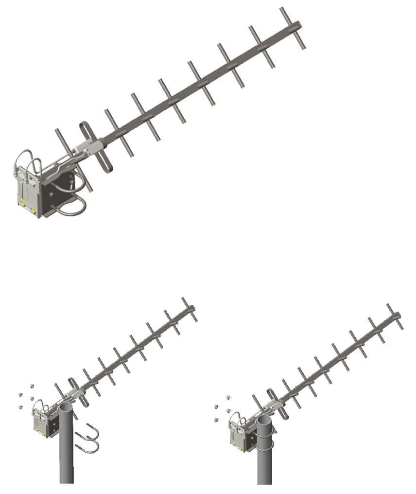
Attaching the SM 900 MHz directional antenna to the pole
1
Unbox the directional Yagi antenna.
Figure 109
PMP 450i SM 900 MHz external directional antenna
2
Attach the directional antenna to the pole and insert the two U clamps into the mounting
bracket of the antenna
Figure 110
Attach the antenna to the pole
Chapter 6: Installation Installing external antennas to a connectorized ODU
Page 6-48
3
Tighten all nuts to approximately 6 to 7 Nm or less to avoid deforming the pole.
Figure 111
Fixing the nuts
Chapter 6: Installation Installing external antennas to a connectorized ODU
Page 6-49
Radio mounting to the antenna
1
Align the radio to E bracket and slide towards right to lock on the antenna as shown in
figure.
Figure 112
Fixing the radio to the antenna
2
Connect the port A of SM to vertical and port B of SM to horizontal polarization interfaces
of the antenna with RF cable.
Figure 113
Connecting RF cable to the radio
Slide towards right to lock
ODU ground cable
Building ground system
Chapter 6: Installation Installing external antennas to a connectorized ODU
Page 6-50
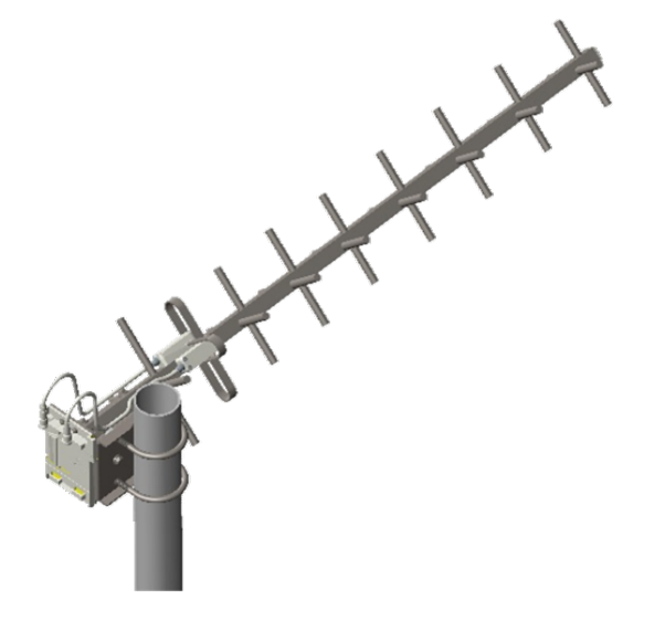
Directional Yagi antenna alignment
The directional Yagi antenna horizontal and vertical alignment procedure is shown below. The
Yagi antenna can be aligned for +15 to -15 degree.
Figure 114 Yagi antenna alignment - horizontally
Figure 115 Yagi antenna alignment - upward tilt
Figure 116 Yagi antenna alignment - downward tilt
Chapter 6: Installation Installing an integrated ODU
Page 6-51
Installing an integrated ODU
Caution
Do not reverse the bracket clamp, as this arrangement may lead to failure of the
assembly. Do not over-tighten the bolts as this may lead to failure of the assembly.
PMP 450m Series – AP
To mount and connect an integrated ODU, proceed as follows:
1
Inventory the parts to ensure that you have them all before you begin. The full set of parts
is shown in Figure 117.
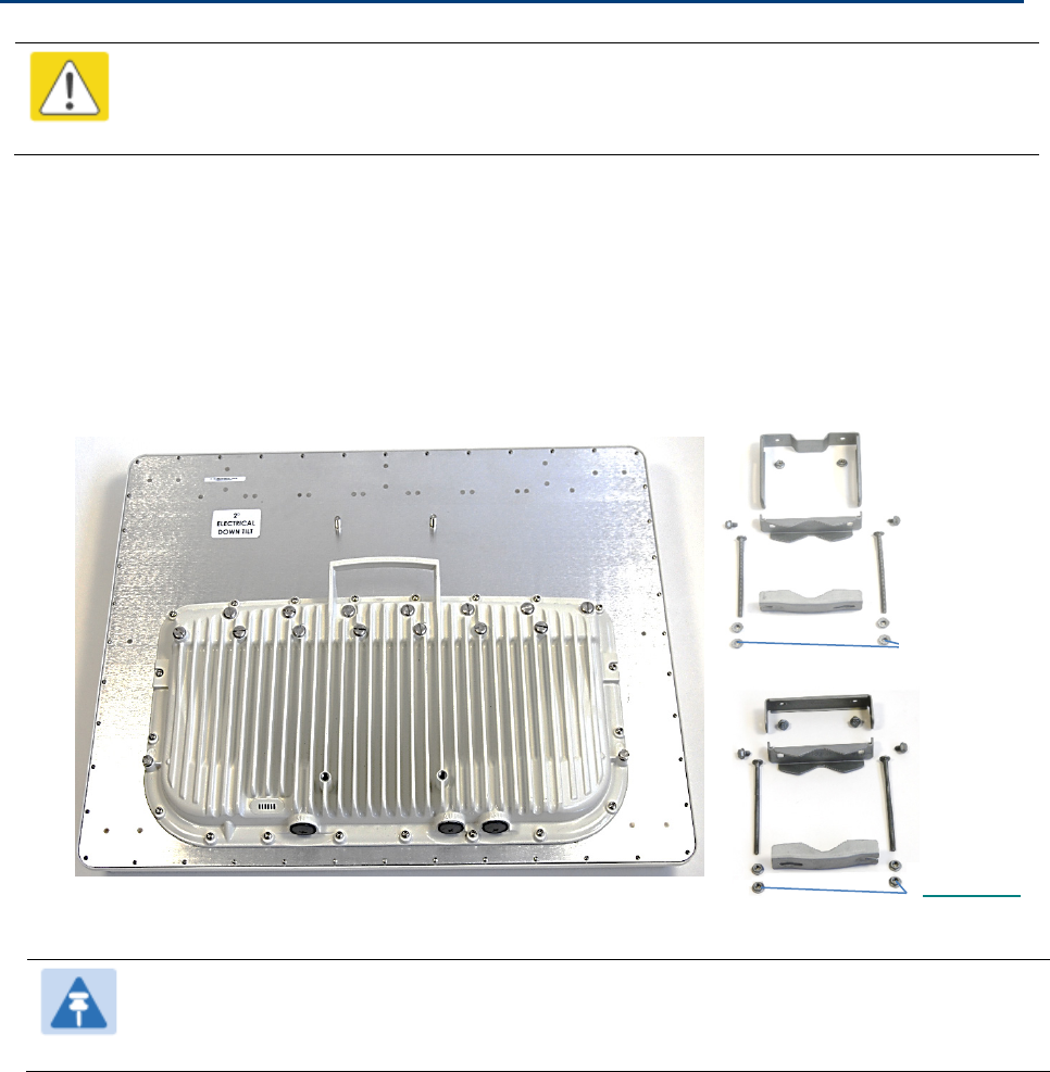
Figure 117
PMP 450m Series - AP unbox view
Note
The additional nuts provided for top and bottom brackets are used to hold the long
bolts in position during installation.
PMP 450m AP Bottom bracket
Top bracket
(Additional
nuts)
(Additional
nuts)
Chapter 6: Installation Installing an integrated ODU
Page 6-52
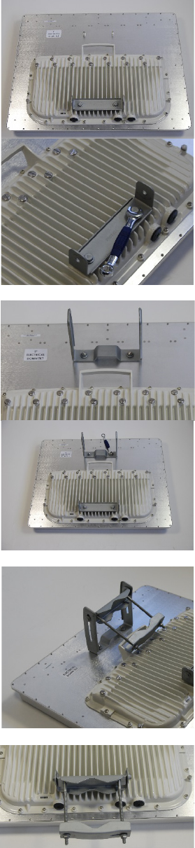
2
Attach the bottom bracket to the ODU using (2) hex
bolts and secure the M8 bolts by applying 5 Nm torque.
3
Attach the top bracket to the projecting studs on the
ODU and secure the top bracket using two M8 nuts by
applying 5 Nm torque.
4
Fix the front and rear strap assembly to the upper
bracket using two bolts. Do not tighten the nuts now.
Note: The PMP 450m antenna operates with 2 degrees
of electrical down-tilt.
5
Fix the front and rear strap assembly to the bottom
bracket using two bolts. Do not tighten the nuts now.
Chapter 6: Installation Installing an integrated ODU
Page 6-53
6
See PMP 450m Series – AP on page 6-3 for the
grounding procedure.
See PMP 450m Series – AP on page 6-6 for the
mounting procedure.
Chapter 6: Installation Installing an integrated ODU
Page 6-54
PMP/PTP 450i Series – AP/SM/BH
To mount and connect an integrated ODU, proceed as follows:
1
Fix the mounting plate to the back of the ODU using the four
M6 bolts, and spring and plain
washers provided. Tighten the bolts to a torque setting of 5.0 Nm (3.7 lb ft).
Figure 118
Fixing the mounting plate to the back of the ODU
2
Attach the bracket body to the mounting plate using the M8 bolt, spring and plain washers.
3
Hoist the ODU to the mounting position.
4
Attach the bracket body to the pole using the bracket clamp, M8 bolts, and spring and plain
washers.
5
If the ODU is mounted outdoors, weatherproof the N type connectors (when antenna alignment
is complete) using PVC tape and
self-amalgamating rubber tape.
Figure 119
Attaching the bracket body
Chapter 6: Installation Connecting Cat5e Ethernet cable
Page 6-55
Connecting Cat5e Ethernet cable
Connecting an RJ45 and gland to a unit
Perform this task to connect the Ethernet cable to an AP.
To connect the Ethernet cable with a gland to an AP unit, proceed as follows:
1
Insert the RJ45 cable through the gland components
2
Insert the RJ45 plug into the socket in the unit, making sure that the locking tab snaps
home.
3
Support the drop cable and gently hand screw the gland body into the unit until the
bushing seal is flush to the unit body.
Note
Do not fit the back shell prior to securing the gland body.
4
Once the gland is fully hand screwed into the unit, tighten it one full rotation only with a 1
1/8 inch spanner wrench.
5
When the gland body has been fitted, tighten the gland back shell.
Caution
Do not over-tighten the gland back shell, as the internal seal and structure or RJ45 port
may be damaged.