Cambium Networks 50450I Fixed Outdoor Point to Multipoint Transceiver User Manual
Cambium Networks Limited Fixed Outdoor Point to Multipoint Transceiver
Contents
- 1. Installation Guide
- 2. User Guide Part 1
- 3. User Guide Part 2
- 4. User Guide Part 3
- 5. User Guide Part 4
- 6. User Guide Part 5
- 7. User Guide Part 6
- 8. User Guide Part 7
- 9. Exhibit D Users Manual per 2 1033 b3
- 10. User Manual - Part 1
- 11. User Manual - Part 2
- 12. User Manual - Part 3
- 13. User Manual - Part 4
- 14. Users Manual - Part 5
- 15. Users Manual - Part 6
- 16. User Manual
Exhibit D Users Manual per 2 1033 b3

Chapter 7: Configuration Configuring a RADIUS server
Page 7-215
Configuring a RADIUS server
Configuring a RADIUS server in a PMP 450 Platform network is optional, but can provide added
security, increase ease of network management and provide usage-based billing data.
Understanding RADIUS for
PMP 450 Platform Family
PMP 450 Platform modules include support for the RADIUS (Remote Authentication Dial In User
Service)
protocol supporting Authentication and Accounting.
RADIUS
Fun
c
tion
s
RADIUS protocol support provides the
following
functions:
SM Authentication allows only known SMs onto the network (blocking
“rogue”
SMs), and
can be configured to ensure SMs are connecting to a known
network
(preventing SMs from
connecting to “rogue” APs). RADIUS authentication is
used
for SMs,
but
is not used for APs.
SM Configuration: Configures authenticated SMs with MIR (Maximum Information Rate), CIR
(Committed Information Rate), High Priority, and VLAN (Virtual LAN) parameters from the
RADIUS server when a SM registers to an AP.
SM Accounting provides support for RADIUS accounting messages for usage-based billing.
This accounting includes indications for subscriber session establishment, subscriber session
disconnection, and bandwidth usage per session for each SM that connects to the AP.
Centralized AP and SM user name and password management allows AP
and
SM
usernames and access levels (Administrator, Installer, Technician) to
be
centrally
administered in the RADIUS server instead of on each radio and tracks
access
events
(logon/logoff) for each username on the RADIUS server. This accounting does not track and
report
specific configuration actions performed on radios or pull statistics such as
bit
counts
from the radios. Such functions require an Element Management
System
(EMS) such as
Cambium Networks Wireless Manager. This accounting is
not
the ability to perform
accounting functions on the subscriber/end
user/customer
account.
Framed IP
allows o
perators to use a RADIUS server to assign management IP addressing to
SM modules (framed IP address).
Tested RADIUS Servers
The Canopy RADIUS implementation has been tested and is supported
on
FreeRADIUS, Version
2.1.8
Aradial RADIUS, Version
5.1.12
Microsoft RADIUS (Windows Server 2012 R2 version)
Cisco ACS, Version 5.7.0.15

Chapter 7: Configuration Configuring a RADIUS server
Page 7-216
Note
Aradial 5.3 has a bug that prevents “remote device login”, so doesn’t support the user
name and password management feature.
Choosing Authentication Mode and Configuring for
Authenti
c
ation Ser
v
er
s - AP
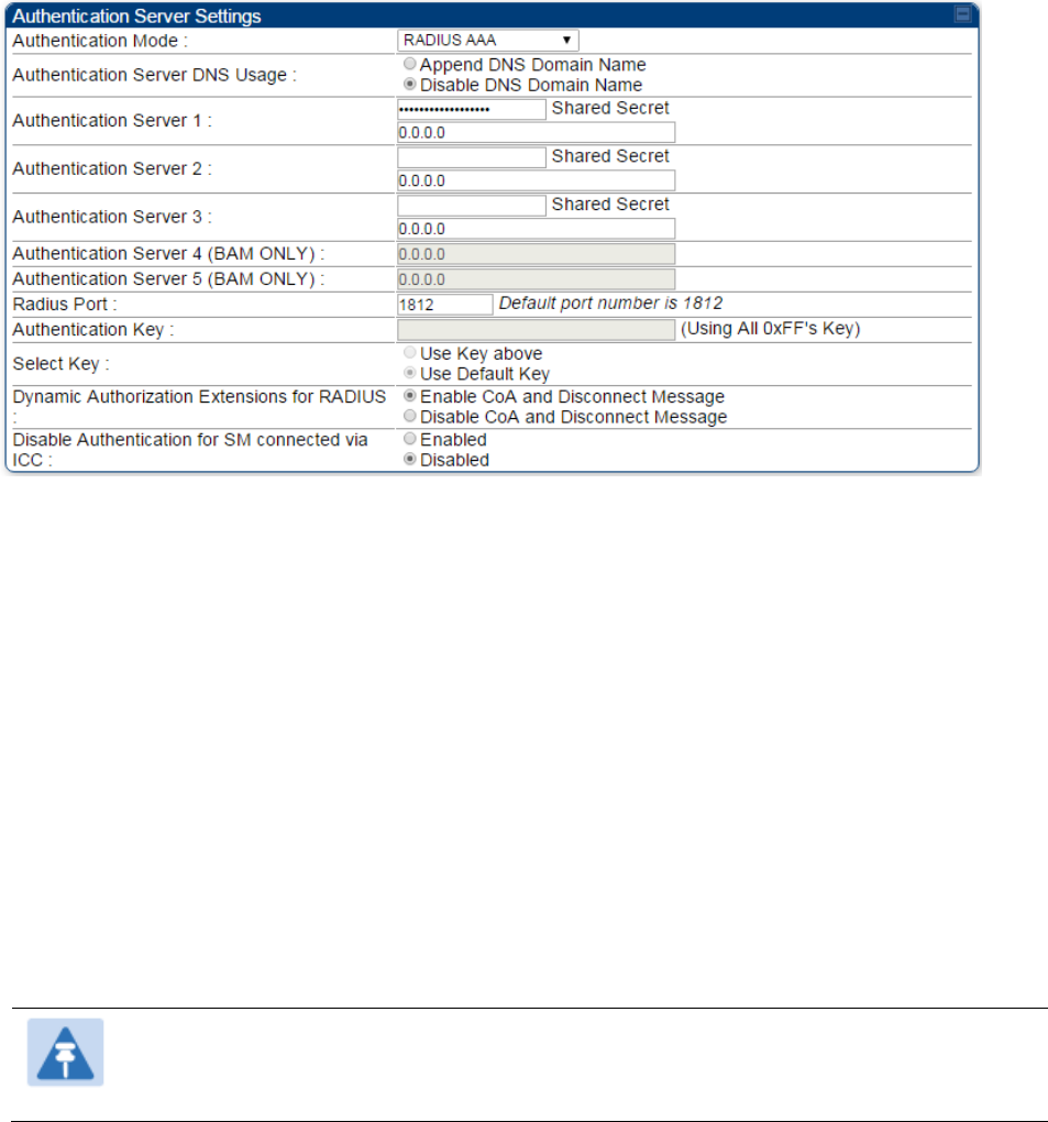
On the AP’s Configuration > Security tab, select the RADIUS AAA Authentication Mode. The
following describes the
other
Authentication Mode options for reference, and then the RADIUS
AAA
option.
Disabled
: Requires no authentication. Any SM (except a SM that itself has been configured
to
require
RADIUS authentication by enabling Enforce Authentication as described below) is
allowed to
register
to the
AP.
Authentication Server: Authentication Server in this instance refers to Wireless Manager in
BAM-only mode. Authentication is
required
for a SM to register to the AP. Only SMs listed
by MAC address in the Wireless Manager database is
allowed to register to the
AP.
AP Pre-Shared
Key
: Canopy offers a pre-shared key authentication option. In this case, an
identical key
must
be entered in the Authentication Key field on the AP’s Configuration >
Security tab
and
in the Authentication Key field on each desired SM’s Configuration >
Security
tab.
RADIUS
AAA
: To support RADIUS authentication of SMs, on the AP’s Configuration >
Security tab
select
RADIUS AAA. Only properly configured SMs with a valid certificate is
allowed to
register
to the
AP.
When RADIUS AAA is selected, up to 3 Authentication Server (RADIUS Server)
IP
addresses
and
Shared Secrets can be configured. The IP address(s) configured here
must
match the IP
address(s) of the RADIUS server(s). The shared secret(s) configured here
must
match the shared
secret(s) configured in the RADIUS server(s). Servers 2 and 3 are meant
for
backup and
reliability, not splitting the database. If Server 1 doesn’t respond, Server 2 is
tried,
and then
server
3. If Server 1 rejects authentication, the SM is denied entry to the network, and does
not
progress trying the other
servers.
The default IP address is 0.0.0.0.
The
default Shared Secret is “CanopySharedSecret”. The
Shared Secret can be up to 32
ASCII
characters (no diacritical marks or ligatures, for
example).
Chapter 7: Configuration Configuring a RADIUS server
Page 7-217
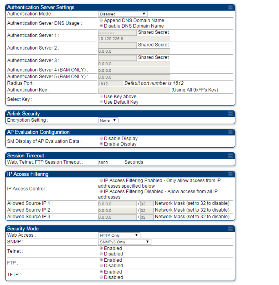
Table 171 Security tab attributes

Chapter 7: Configuration Configuring a RADIUS server
Page 7-218
Attribute Meaning
Authentication Mode Operators may use this field to select the following authentication
modes:
Disabled—the AP requires no SMs to authenticate.
Authentication Server —the AP requires any SM that attempts
registration to be authenticated in Wireless Manager before registration.
AP PreShared Key - The AP acts as the authentication server to its SMs
and will make use of a user-configurable pre-shared authentication key.
The operator enters this key on both the AP and all SMs desired to
register to that AP. There is also an option of leaving the AP and SMs at
their default setting of using the “Default Key”. Due to the nature of the
authentication operation, if you want to set a specific authentication key,
then you MUST configure the key on all of the SMs and reboot them
BEFORE enabling the key and option on the AP. Otherwise, if you
configure the AP first, none of the SMs is able to register.
RADIUS AAA - When RADIUS AAA is selected, up to 3 Authentication
Server (RADIUS Server) IP addresses and Shared Secrets can be
configured. The IP address(s) configured here must match the IP
address(s) of the RADIUS server(s). The shared secret(s) configured here
must match the shared secret(s) configured in the RADIUS server(s).
Servers 2 and 3 are meant for backup and reliability, not for splitting the
database. If Server 1 doesn’t respond, Server 2 is tried, and then server
3. If Server 1 rejects authentication, the SM is denied entry to the
network and does not progress trying the other servers.
Authentication
Server DNS Usage
The management DNS domain name may be toggled such that the
name of the authentication server only needs to be specified and the
DNS domain name is automatically appended to that name.
Authentication
Server 1
Enter the IP address or server name of the authentication server
(RADIUS or WM) and the Shared Secret configured in the authentication
server. When Authentication Mode RADIUS AAA is selected, the default
value of Shared Secret is “CanopySharedSecret”. The Shared Secret
may consist of up to 32 ASCII characters.
Authentication
Server 2
Authentication
Server 3
Authentication
Server 4 (BAM Only)
Authentication
Server 5 (BAM Only)
Radius Port This field allows the operator to configure a custom port for RADIUS
server communication. The default value is 1812.
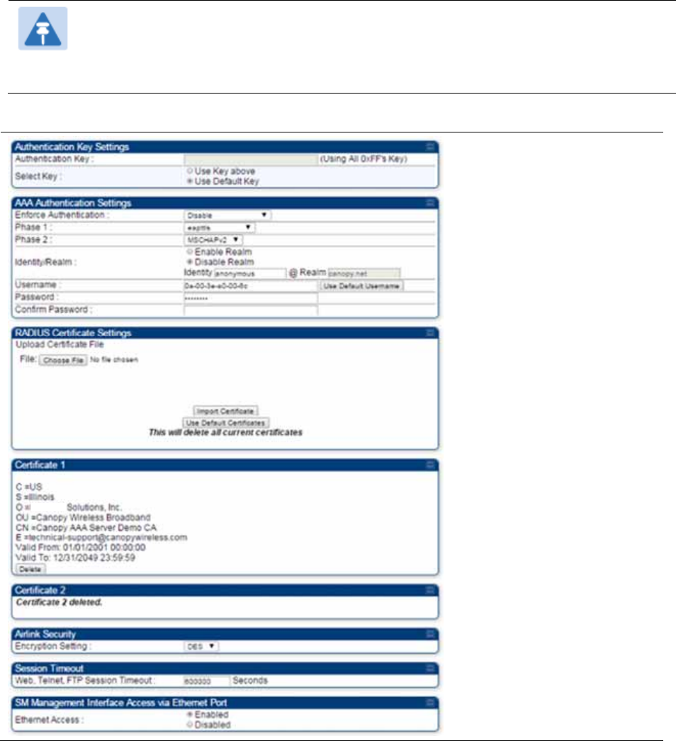
Authentication Key The authentication key is a 32-character hexadecimal string used when
Authentication Mode is set to AP Pre-Shared Key. By default, this key is
set to 0xFFFFFFFFFFFFFFFFFFFFFFFFFFFFFFFF.

Chapter 7: Configuration Configuring a RADIUS server
Page 7-219
Selection Key This option allows operators to choose which authentication key is used:
Use Key above means that the key specified in Authentication Key is
used for authentication
Use Default Key means that a default key (based off of the SM’s MAC
address) is used for authentication
Encryption Key Specify the type of airlink security to apply to this AP. The encryption
setting must match the encryption setting of the SMs.
None provides no encryption on the air link.
DES (Data Encryption Standard): An over-the-air link encryption option
that uses secret 56-bit keys and 8 parity bits. DES performs a series of bit
permutations, substitutions, and recombination operations on blocks of
data. DES encryption does not affect the performance or throughput of
the system.
AES (Advanced Encryption Standard): An over-the-air link encryption
option that uses the Rijndael algorithm and 128-bit keys to establish a
higher level of security than DES. AES products are certified as
compliant with the Federal Information Processing Standards (FIPS 197)
in the U.S.A.
SM Display of AP
Evaluation Data
You can use this field to suppress the display of data about this AP on
the AP Evaluation tab of the Tools page in all SMs that register.
Web, Telnet, FTP
Session Timeout
Enter the expiry in seconds for remote management sessions via HTTP,
telnet, or ftp access to the AP.
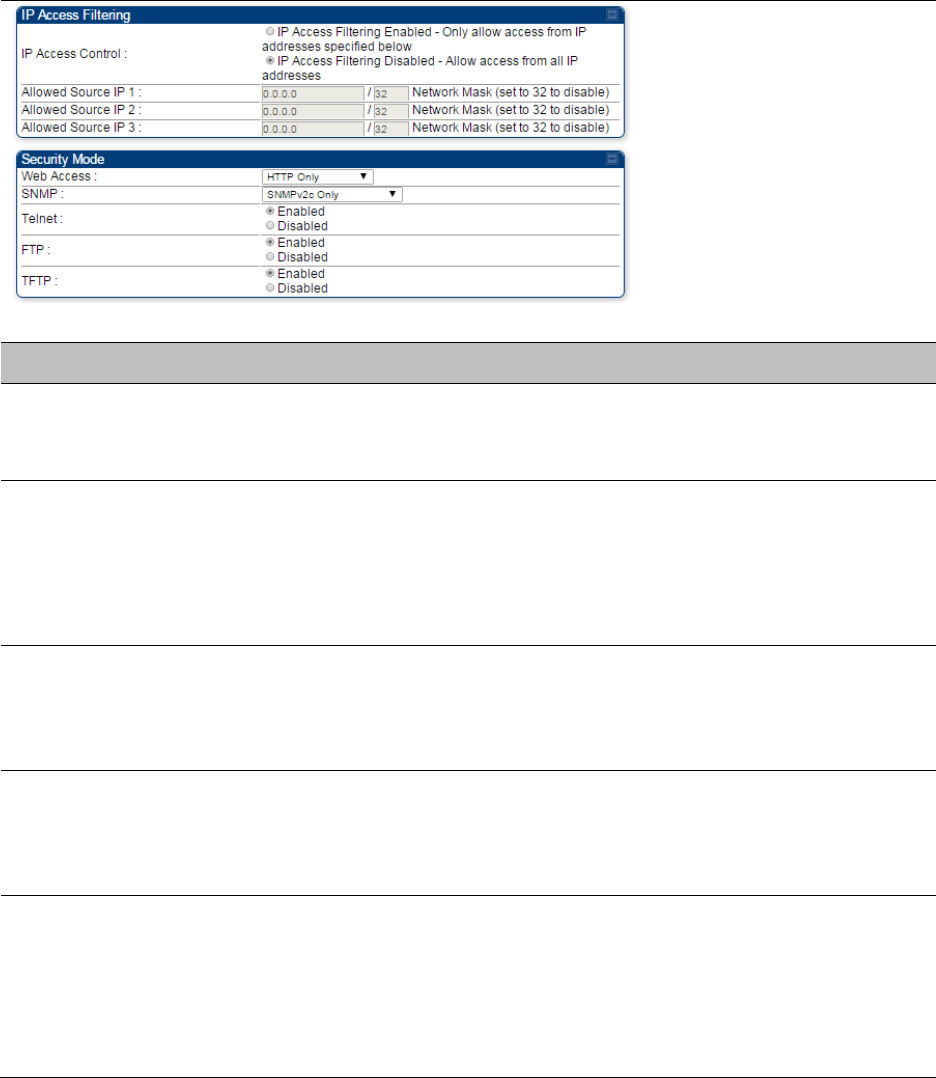
IP Access Control You can permit access to the AP from any IP address (IP Access Filtering
Disabled) or limit it to access from only one, two, or three IP addresses
that you specify (IP Access Filtering Enabled). If you select IP Access
Filtering Enabled, then you must populate at least one of the three
Allowed Source IP parameters or have no access permitted from any IP
address
Allowed Source IP 1 If you selected IP Access Filtering Enabled for the IP Access Control
parameter, then you must populate at least one of the three Allowed
Source IP parameters or have no access permitted to the AP from any IP
address. You may populate as many as all three.
Allowed Source IP 2 If you selected IP Access Filtering Disabled for the IP Access Control
parameter, then no entries in this parameter are read, and access from
all IP addresses is permitted.
Allowed Source IP 3
Web Access The Radio supports secured and non-secured web access protocols.
Select suitable web access from drop down list:
HTTP Only – provides non-secured web access. The radio to be
accessed via http://<IP of Radio>.
HTTPS Only – provides a secured web access. The radio to be
accessed via https1://<IP of Radio>.

Chapter 7: Configuration Configuring a RADIUS server
Page 7-220
HTTP and HTTPS – If enabled, the radio can be accessed via both
http and https.
SNMP This option allows to configure SNMP agent communication version. It
can be selected from drop down list :
SNMPv2c Only – Enables SNMP v2 community protocol.
SNMPv3 Only – Enables SNMP v3 protocol. It is secured
communication protocol.
SNMPv2c and SNMPv3 – It enables both the protocols.
Telnet This option allows to Enable and Disable Telnet access to the Radio.
FTP This option allows to Enable and Disable FTP access to the Radio.
TFTP This option allows to Enable and Disable TFTP access to the Radio.
Chapter 7: Configuration Configuring a RADIUS server
Page 7-221
SM Authentication Mode – Require RADIUS or Follow
AP
If it is desired that a SM will only authenticate to an AP that is using RADIUS, on the
SM’s
Configuration Security tab set Enforce Authentication to AAA. With this enabled, SM
does
not
register to an AP that has any Authentication Mode other than RADIUS AAA
selected
.
If it is desired that a SM use the authentication method configured on the AP it is
registering
to,
set Enforce Authentication to Disabled. With Enforce Authentication disabled, a SM will
attempt to register
using
whichever Authentication Mode is configured on the AP it is attempting
to register
to.
Note
Having SMs to use RADIUS by enabling Enforce Authentication avoids the security
issue
of
SMs possibly registering to “rogue” APs, which have authentication
disabled.
Table 172 SM Security tab attributes
Chapter 7: Configuration Configuring a RADIUS server
Page 7-222
Attribute Meaning
Authentication Key
The authentication key is a 32-character hexadecimal string used when
Authentication Mode is set to AP PreShared Key. By default, this key is
set to 0xFFFFFFFFFFFFFFFFFFFFFFFFFFFFFFFF.
Select Key
This option allows operators to choose which authentication key is used:
Use Key above means that the key specified in Authentication Key is
used for authentication
Use Default Key means that a default key (based off of the SM’s MAC
address) is used for authentication
Enforce
Authentication
The SM may enforce authentication types of AAA and AP Pre-
sharedKey. The SM will not finish the registration process if the AP is not
using the configured authentication method (and the SM locks out the
AP for 15 minutes). Enforce Authentication default setting is Disable.
Phase 1
The protocols supported for the Phase 1 (Outside Identity) phase of
authentication are
EAPTTLS (Extensible Authentication Protocol
Tunneled Transport Layer
Security) or MSCHAPv2 (Microsoft
Challenge-Handshake Authentication Protocol version 2).
Phase 2
Select the desired Phase 2 (Inside Identity) authentication protocol from
the Phase 2 options
of
PAP (Password Authentication Protocol), CHAP
(Challenge Handshake
Authentication
Protocol), and MSCHAP
(Microsoft’s version of CHAP, version 2 is used). The protocol
must
be
consistent with the authentication protocol configured on the RADIUS
server.

Chapter 7: Configuration Configuring a RADIUS server
Page 7-223
Identity/Realm
If Realms are being used, select Enable Realm and configure an outer
identity in the
Identity
field and a Realm in the Realm field. These must
match the Phase 1/Outer Identity and
Realm
configured in the RADIUS
server. The default Identity is “anonymous”. The Identity can be
up
to
128 non-special (no diacritical markings) alphanumeric characters. The
default Realm
is
“canopy.net”. The Realm can also be up to 128 non-
special alphanumeric
characters.
Configure an outer Identity in the Username field. This must match the
Phase
1/Outer
Identity username configured in the RADIUS server. The
default Phase 1/Outer
Identity
Username is “anonymous”. The
Username can be up to 128 non-special (no
diacritical
markings)
alphanumeric
characters.
Username
Enter a Username for the SM. This must match the username
configured for the SM on
the
RADIUS server. The default Username is
the SM’s MAC address. The Username can be up
to
128 non-special
(no diacritical markings) alphanumeric
characters.
Password Enter the desired password for the SM in the Password and Confirm
Password fields.
The
Password must match the password configured
for the SM on the RADIUS server.
The
default Password is “password”.
The Password can be up to 128 non-special (no
diacritical
markings)
alphanumeric
characters.
Confirm Password
Upload Certificate
File
To upload a certificate manually to a SM, first load it in a known place
on your PC
or
network
drive, then click on a Delete button on one of
the Certificate description blocks
to
delete a certificate to provide space
for your certificate. Click on Choose File, browse to
the
location of the
certificate, and click the Import Certificate button, and then reboot the
radio
to
use the new certificate.
When a certificate is in use, after the SM successfully registers to an
AP, an indication of In
Use
will appear in the description block of the
certificate being
used.
The public certificates installed on the SMs are used with the private
certificate on the
RADIUS
server to provide a public/private key
encryption
system.
Up to 2 certificates can be resident on a SM. An installed certificate can
be deleted
by
clicking the Delete button in the certificate’s description
block on the Configuration >
Security
tab. To restore the 2 default
certificates, click the Use Default Certificates button in
the
RADIUS
Certificate Settings parameter block and reboot the
radio.

Chapter 7: Configuration Configuring a RADIUS server
Page 7-224
Encryption Setting
Specify the type of airlink security to apply to this AP. The encryption
setting must match the encryption setting of the SMs.
None provides no encryption on the air link.
DES (Data Encryption Standard): An over-the-air link encryption option
that uses secret 56-bit keys and 8 parity bits. DES performs a series of bit
permutations, substitutions, and recombination operations on blocks of
data. DES encryption does not affect the performance or throughput of
the system.
AES (Advanced Encryption Standard): An over-the-air link encryption
option that uses the Rijndael algorithm and 128-bit keys to establish a
higher level of security than DES. AES products are certified as
compliant with the Federal Information Processing Standards (FIPS 197)
in the U.S.A.
Web, Telnet, FTP
Session Timeout
Enter the expiry in seconds for remote management sessions via HTTP,
telnet or ftp access to the AP.
Ethernet Access
If you want to prevent any device that is connected to the Ethernet port
of the SM from accessing the management interface of the SM, select
Ethernet Access Disabled. This selection disables access through this
port to via HTTP (the GUI), SNMP, telnet, FTP, and TFTP. With this
selection, management access is available through only the RF interface
via either an IP address (if Network Accessibility is set to Public on the
SM) or the Session Status or Remote Subscribers tab of the AP. See IP
Access Control below.
If you want to allow management access through the Ethernet port,
select Ethernet Access Enabled. This is the factory default setting for this
parameter.
IP Access Control
You can permit access to the AP from any IP address (IP Access Filtering
Disabled) or limit it to access from only one, two, or three IP addresses
that you specify (IP Access Filtering Enabled). If you select IP Access
Filtering Enabled, then you must populate at least one of the three
Allowed Source IP parameters or have no access permitted from any IP
address
Allowed Source IP 1 If you selected IP Access Filtering Enabled for the IP Access Control
parameter, then you must populate at least one of the three Allowed
Source IP parameters or have no access permitted to the AP from any IP
address. You may populate as many as all three.
If you selected IP Access Filtering Disabled for the IP Access Control
parameter, then no entries in this parameter are read, and access from
all IP addresses is permitted.
Allowed Source IP 2
Allowed Source IP 3
Web Access The Radio supports secured and non-secured web access protocols.
Select suitable web access from drop down list:
HTTP Only – provides non-secured web access. The radio to be
accessed via http://<IP of Radio>.

Chapter 7: Configuration Configuring a RADIUS server
Page 7-225
HTTPS Only – provides a secured web access. The radio to be
accessed via https://<IP of Radio>.
HTTP and HTTPS – If enabled, the radio can be accessed via both
http and https.
SNMP This option allows to configure SNMP agent communication version. It
can be selected from drop down list :
SNMPv2c Only – Enables SNMP v2 community protocol.
SNMPv3 Only – Enables SNMP v3 protocol. It is secured
communication protocol.
SNMPv2c and SNMPv3 – It enables both the protocols.
Telnet This option allows to Enable and Disable Telnet access to the Radio.
FTP This option allows to Enable and Disable FTP access to the Radio.
TFTP This option allows to Enable and Disable TFTP access to the Radio.
SM - Phase 1 (Outside Identity) parameters and
s
ettin
gs
The protocols supported for the Phase 1 (Outside Identity) phase of authentication
are
eapttls (Extensible Authentication Protocol Tunneled Transport Layer
Security) and
eapMSChapV2
(Extensible Authentication Protocol – Microsoft Challenge-Handshake
Authentication Protocol).
Configure an outer Identity in the Username field. This must match the Phase
1/Outer
Identity
username configured in the RADIUS server. The default Phase 1/Outer
Identity
Username is
“anonymous”. The Username can be up to 128 non-special (no
diacritical
markings)
alphanumeric
characters.
If Realms are being used in the RADIUS system (eapttls only), select
Enable Realm and configure an outer identity in the
Identity
field and a Realm in the Realm field.
These must match the Phase 1/Outer Identity and
Realm
configured in the RADIUS server. The
default Identity is “anonymous”. The Identity can be
up
to
128 non-special (no diacritical markings)
alphanumeric characters. The default Realm
is
“canopy.net”. The Realm can also be up to 128 non-
special alphanumeric
characters.
SM - Phase 2 (Inside Identity) parameters and
s
ettin
gs
If using eapttls for Phase 1 authentication, select the desired Phase 2 (Inside Identity)
authentication protocol from the Phase 2 options
of
PAP (Password Authentication Protocol),
CHAP (Challenge Handshake
Authentication
Protocol), and MSCHAPv2 (Microsoft’s version of
CHAP). The protocol
must
be
consistent with the authentication protocol configured on the
RADIUS
server.
Enter a Username for the SM. This must match the username configured for the
SM on
the
RADIUS server. The default Username is the SM’s MAC address. The Username can
be up
to
128 non-special (no diacritical markings) alphanumeric
characters.
Enter the desired password for the SM in the Password and Confirm Password fields.
The
Password must match the password configured for the SM on the RADIUS server.
The
default
Password is “password”. The Password can be up to 128 non-special (no
diacritical
markings)
alphanumeric
characters.

Chapter 7: Configuration Configuring a RADIUS server
Page 7-226
Handling Certificates
Managing SM Certificates via the SM GUI
The default public Canopy certificates are loaded into SMs upon factory software installation.
The default certificates are not secure and are intended for
use
during lab and field trials as part
of gaining experience with the RADIUS functionalities or as
an
option during debug. For secure
operation, an operator will want to create or procure their
own
certificates. Resetting a SM to its
factory defaults will remove the current certificates and restore the default certificates.
Up to two certificates can be resident on a SM. An installed certificate can be deleted
by
clicking
the Delete button in the certificate’s description block on the Configuration >
Security
tab. To
restore the 2 default certificates, click the Use Default Certificates button in
the
RADIUS
Certificate Settings parameter block and reboot the
radio.
To upload a certificate manually to a SM, first load it in a known place on your PC
or
network
drive, then click on a Delete button on one of the Certificate description blocks
to
delete a
certificate to provide space for your certificate. Click on Choose File, browse to
the
location of the
certificate, and click the Import Certificate button, and then reboot the radio
to
use the new
certificate.
When a certificate is in use, after the SM successfully registers to an AP, an indication of In
Use
will appear in the description block of the certificate being
used.
The public certificates installed on the SMs are used with the private certificate on the
RADIUS
server to provide a public/private key encryption
system.
Note
Root certificates of more than one level (Example - a certificate from someone who
received their CA from Verisign) fails. Certificates must be either root or self-signed.
Chapter 7: Configuration Configuring a RADIUS server
Page 7-227
Figure 144 SM Certificate Management
Configuring RADIUS servers for SM authentication
Your RADIUS server must be configured to use the
following:
EAPTTLS or MSCHAPv2 as the Phase 1/Outer Identity
protocol.
If Enable Realm is selected on the SM’s Configuration > Security tab, then the
same
Realm
appears there (or access to it).
The same Phase 2 (Inner Identity) protocol as configured on the SM’s
Configuration
>
Security tab under Phase 2 options.
The username and password for each SM configured on each SM’s
Configuration
> Security
tab.
An IP address and NAS shared secret that is the same as the IP address
and
Shared Secret
configured on the AP’s Configuration > Security tab for
that
RADIUS server.

Chapter 7: Configuration Configuring a RADIUS server
Page 7-228
A server private certificate, server key, and CA certificate that complement
the
public
certificates distributed to the SMs, as well as the Canopy dictionary file
that
defines Vendor
Specific Attributes (VSAa). Default certificate files and
the
dictionary
file are available from
the software
site:
https://support.cambiumnetworks.com/files/pmp450 after entering your
name,
email address, and either Customer Contract Number or the MAC address of
a
module covered under the 12 month
warranty.
Optionally, operators may configure the RADIUS server response messages (Accept or Reject) so
that the user has information as to why they have been rejected. The AP displays the RADIUS
Authentication Reply message strings in the Session Status list as part of each SM’s information.
The SM will show this string (listed as Authentication Response on the SM GUI) on the main
Status page in the Subscriber Module Stats section.
Note
Aradial AAA servers only support operator-configurable Authentication Accept
responses, not Authentication Reject responses.

Chapter 7: Configuration Configuring a RADIUS server
Page 7-229
Assigning SM management IP addressing via RADIUS
Operators may use a RADIUS AAA server to assign management IP addressing to SM modules
(framed IP address). SMs now interpret attributes Framed-IP-Address, Framed-IP-Netmask, and
Cambium-Canopy-Gateway from RADIUS. The RADIUS dictionary file has been updated to include
the Cambium-Canopy-Gateway attribute and is available on the Cambium Software Support
website.
In order for these attributes to be assigned and used by the SM, the following must be true:
The system is configured for AAA authentication
The SM is not configured for DHCP on its management interface. If DHCP is enabled and these
attributes are configured in the RADIUS server, the attributes is ignored by the SM.
The SM management interface must be configured to be publically accessible. If the SM is
configured to have local accessibility, the management interface will still be assigned the
framed addressing, and the SM iscome publicly accessible via the assigned framed IP
addressing.
When using these attributes, for the addressing to be implemented by the SM operators must
configure Framed-IP-Address in RADIUS. If Framed-IP-Address is not configured but Framed-
IP-Netmask and/or Cambium-Canopy-Gateway is configured, the attributes is ignored. In the
case where only the Framed-IP-Address is configured, Framed-IP-Netmask defaults to
255.255.0.0 (NAT disabled) / 255.255.255.0 (NAT enabled) and Cambium-Canopy-Gateway
defaults to 0.0.0.0.
Configuring RADIUS server for SM configuration
Canopy Vendor Specific Attributes (VSAs) along with VSA numbers and
other
details are listed
in Table 173. The associated SM GUI page, tab and parameter are listed to aid
cross-referencing
and understanding of the
VSAs.
A RADIUS dictionary file is available from the software
site:
https://support.cambiumnetworks.com/files/pmp450
The RADIUS dictionary file
defines
the VSAs and their values and is usually imported into the
RADIUS server as part of
server
and database
setup.
Chapter 7: Configuration Configuring a RADIUS server
Page 7-230
Note
Beginning with System Release 12.0.2, two RADIUS dictionary files are available on
the Cambium website – “RADIUS Dictionary file – Cambium” and “RADIUS Dictionary
file – Motorola”.
In addition to a renaming of attributes, the Cambium-branded dictionary file contains
two new VSAs for controlling uplink and downlink Maximum Burst Data Rate (these
VSAs are listed below in Table 173).
If you are transitioning from the Motorola-branded dictionary file to the Cambium-
branded dictionary file, ensure that all RADIUS profiles containing Motorola-Canopy
attribute references are updated to include Cambium-Canopy attribute references (for
all applicable VSAs listed in Table 173). Also, ensure that all RADIUS configuration
files reference the new dictionary file (as an alternative, operators may rename the
Cambium-branded dictionary file to the filename currently in use by the RADIUS
server). Once the profiles are updated and the new Cambium-branded dictionary file is
installed on the RADIUS server, restart the RADIUS server to ensure that the new
VSAs and attribute names are enabled.
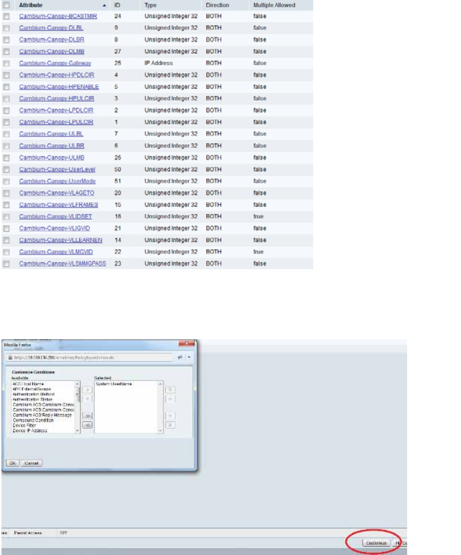
Table 173 RADIUS Vendor Specific Attributes (VSAs)
Name Number Type Required
Value
MS-MPPE-Send-Key
*
26.311.16
-
Y
-
-
- -
MS-MPPE-Recv-Key
*
26.311.17
-
Y
-
-
-
-
Cambium-Canopy-LPULCIR
26.161.1
integer N
0-65535
kbps
Configuration > Quality of Service > Low Priority Uplink
CIR
0
kbps
32 bits
Cambium-Canopy-LPDLCIR
26.161.2
integer N
0-65535
kbps
Configuration > Quality of Service > Low Priority Downlink
CIR
0
kbps
32 bits
Cambium-Canopy-HPULCIR
26.161.3
integer
N
0-65535
kbps
Configuration > Quality of Service > Hi Priority Uplink
CIR
0
kbps
32 bits
Cambium-Canopy-HPDLCIR
26.161.4
integer
N
0-65535
kbps
Configuration > Quality of Service > Hi Priority Uplink
CIR
0
kbps
32 bits
Cambium-Canopy-HPENABLE
26.161.5
integer
N
0-disable,
1-enable
Configuration > Quality of Service > Hi Priority
Channel
Enable/Disable
0
32 bits
26.161.6
integer
N
0-100000
kbps

Chapter 7: Configuration Configuring a RADIUS server
Page 7-231
Configuration > Quality of Service > Sustained Uplink
Data
Rate
dependent
on
radio
feature
set
32 bits
Cambium-Canopy-ULBL
26.161.7
integer
N
0-2500000
kbps
Configuration > Quality of Service > Uplink Burst
Allocation
dependent
on
radio
feature
set
32 bits
Cambium-Canopy-DLBR
26.161.8
integer N
0-100000
kbps
Configuration > Quality of Service > Sustained Downlink
Data
Rate
dependent
on
radio
feature
set
32 bits
Cambium-Canopy-DLBL
26.161.9
integer
N
0-2500000
kbps
Configuration > Quality of Service > Downlink Burst
Allocation
dependent
on
radio
feature
set
32 bits
Cambium-Canopy-
VLLEARNEN
26.161.14
integer
N
0-disable,
1-enable
Configuration > VLAN > Dynamic
Learning 1
32 bits
Cambium-Canopy-
VLFRAMES
26.161.15 integer
N
0-all, 1-tagged,
2-
untagged
Configuration > VLAN > Allow Frame
Types 0
32 bits
Cambium-Canopy-VLIDSET
26.161.16 integer N
VLAN Membership
(1-4094)
Configuration > VLAN
Membership 0
32 bits
Cambium-Canopy-VLAGETO
26.161.20 integer
N
5 - 1440
minutes
Configuration > VLAN > VLAN Aging
Timeout
25
mins
32 bits
Cambium-Canopy-VLIGVID
26.161.21
integer
N
1 –
4094
Configuration > VLAN > Default Port
VID 1
32 bits
Cambium-Canopy-VLMGVID
26.161.22 integer
N
1 –
4094
Configuration > VLAN > Management
VID 1
32 bits
Cambium-Canopy-
VLSMMGPASS
26.161.23 integer
N
0-disable,
1-enable
Configuration > VLAN > SM Management VID
Pass-through 1
32 bits
Cambium-Canopy-BCASTMIR
26.161.24 integer
N
0-100000 kbps,
0=disabled
Configuration > Quality of Service > Broadcast/Multicast
Uplink
Data Rate
dependent
on
radio
feature
set
32 bits
Cambium-Canopy-Gateway
26.161.25 ipaddr N
-
Configuration > IP > Gateway IP Address
0.0.0.0 -

Chapter 7: Configuration Configuring a RADIUS server
Page 7-232
Cambium-Canopy-ULMB 26.161.26
integer
N
0-100000 kbps
Configuration > Quality of Service > Max Burst Uplink Data
Rate
0 32 bits
Cambium-Canopy-DLMB 26.161.27
integer
N
0-100000 kbps
Configuration > Quality of Service > Max Burst Downlink Data
Rate
0 32 bits
Cambium-Canopy-UserLevel 26.161.50
integer
N
1-Technician,
2-
Installer, 3-
Administrator
Account > Add User >
Level 0
32 bits
Cambium-Canopy-DHCP-
State
26.161.31 integer N 1-Enable
Configuration > IP > DHCP
state
1 32
bits
Cambium-Canopy-
BCASTMIRUNITS
26.161.28
integer
N
Configuration > QoS >
Broadcast Downlink CIR
0
32 bits
Cambium-Canopy-
ConfigFileImportUrl
26.161.29
string
N
Configuration > Unit Settings
0 32 bits
Cambium-Canopy-
ConfigFileExportUrl
26.161.30 string N
Configuration > Unit Settings 0 32 bits
Cambium-Canopy-UserMode 26.161.51 integer N 1=Read-Only 0=Read-
Write
Account > Add User > User
Mode
0 32 bits
(*) Contains key for encrypting packets sent by the NAS to the remote host (for Microsoft Point-
to-Point Encryption Protocol).
Note
VSA
numbering:
26 connotes Vendor Specific Attribute, per RFC
2865
26.311 is Microsoft Vendor Code, per
IANA

Chapter 7: Configuration Configuring a RADIUS server
Page 7-233
Configuring RADIUS server for SM configuration using Zero
Touch feature
The RADIUS VSA (Vendor Specific Attributes) is updated for Zero Touch feature. This feature
enables the ability for a SM to get its configuration via RADIUS VSA. The RADIUS VSA is updated
for an URL which points to the configuration file of SM (see Table 173 for list of VSA).
The RADIUS will push the vendor specific attribute to SM after successful authentication. The VSA
contains URL of config file which will redirect SM to download configuration. If there is any change
in SM confirmation, the SM will reboot automatically after applying the configuration.
The RADIUS VSA attributes concerning Zero Touch are as follows:
VSA Type String
Cambium-Canopy-ConfigFileImportUrl (29) string Maximum Length 127
characters.
Cambium-Canopy-ConfigFileExportUrl (30) string Maximum Length 127
characters.
The updated RADIUS dictionary can be downloaded from below link:
https://support.cambiumnetworks.com/files/pmp450/
Note
The feature is not applicable to the AP.
Chapter 7: Configuration Configuring a RADIUS server
Page 7-234
Using RADIUS for centralized AP and SM user name and
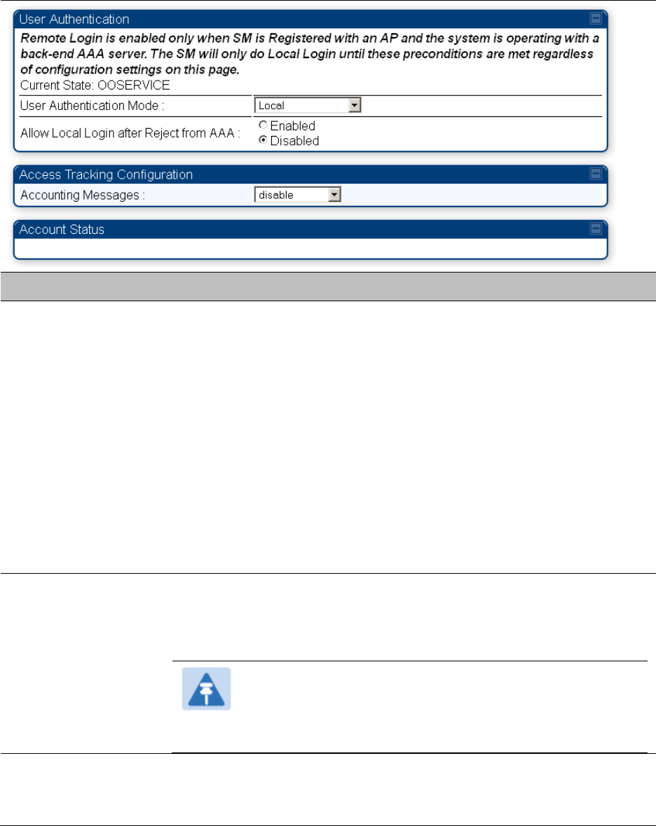
password management
AP – Technician/Installer/Administrator
Authenti
c
ation
To control technician, installer, and administrator access to the AP from a centralized
RADIUS
server:
Procedure 28 Centralized user name and password management for AP
1 Set Authentication Mode on the AP’s Configuration > Security tab
to
RADIUS AAA
2 Set User Authentication Mode on the AP’s Account > User Authentication
tab
(the tab
only appears after the AP is set to RADIUS authentication) to
Remote
or Remote then
Local
.
Local: The local SM is checked for accounts. No centralized
RADIUS
accounting
(access control)
is
performed.
Remote: Authentication by the centralized RADIUS server
is
required to gain access
to the SM if the SM is registered to an
AP
that has RADIUS AAA Authentication
Mode selected. For up to
2
minutes a test pattern is displayed until the server
responds
or
times
out.
Remote then Local: Authentication using the centralized
RADIUS
server is
attempted. If the server sends a reject message, then
the
setting of Allow Local
Login after Reject from AAA determines
if
the local user database is checked or
not. If the configured
servers
do
not respond within 2 minutes, then the local user
database
is
used. The successful login method is displayed in the
navigation
column of the SM.
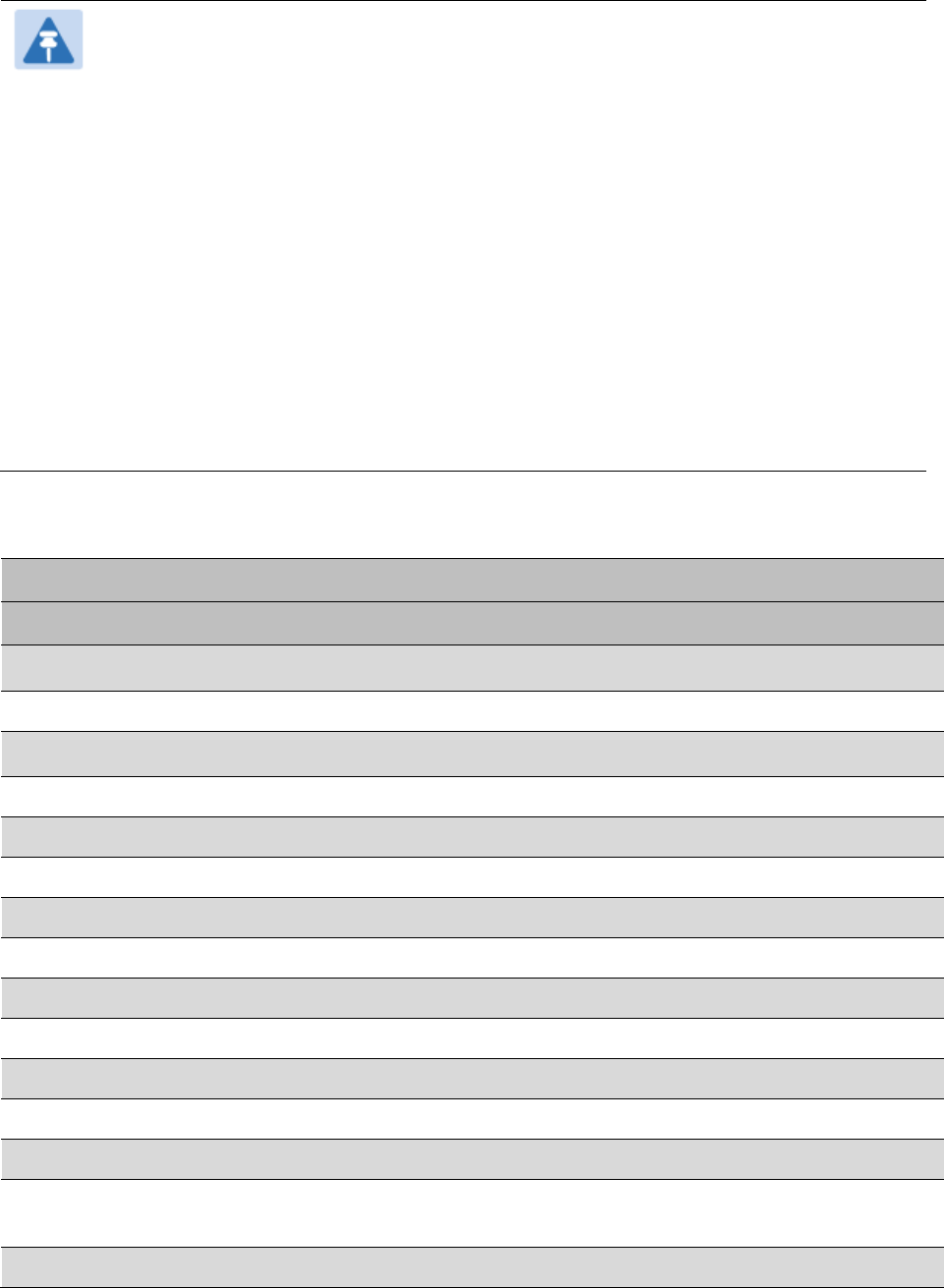
Figure 145 User Authentication and Access Tracking tab of the AP
Table 174 AP User Authentication and Access Tracking attributes
Chapter 7: Configuration Configuring a RADIUS server
Page 7-235
Attribute Meaning
User Authentication
Mode
Local: The local SM is checked for accounts. No centralized
RADIUS
accounting (access control)
is
performed.
Remote: Authentication by the centralized RADIUS server
is
required to gain access to the AP. For up to
2
minutes a test pattern
is displayed until the server responds
or
times
out.
Remote then Local: Authentication using the centralized
RADIUS
server is attempted. If the server sends a reject message, then
the
setting of Allow Local Login after Reject from AAA determines
if
the local user database is checked or not. If the configured
servers
do
not respond within 2 minutes, then the local user database
is
used. The successful login method is displayed in the
navigation
column of the AP.
User Authentication
Method
The user authentication method employed by the radios is EAP-MD5.
Allow Local Login after
Reject from AAA
If a user authentication is rejected from the AAA server, the user is
allowed to login locally to the radio’s management interface.
Radius Accounting
Port
The destination port on the AAA server used for Radius accounting
communication.
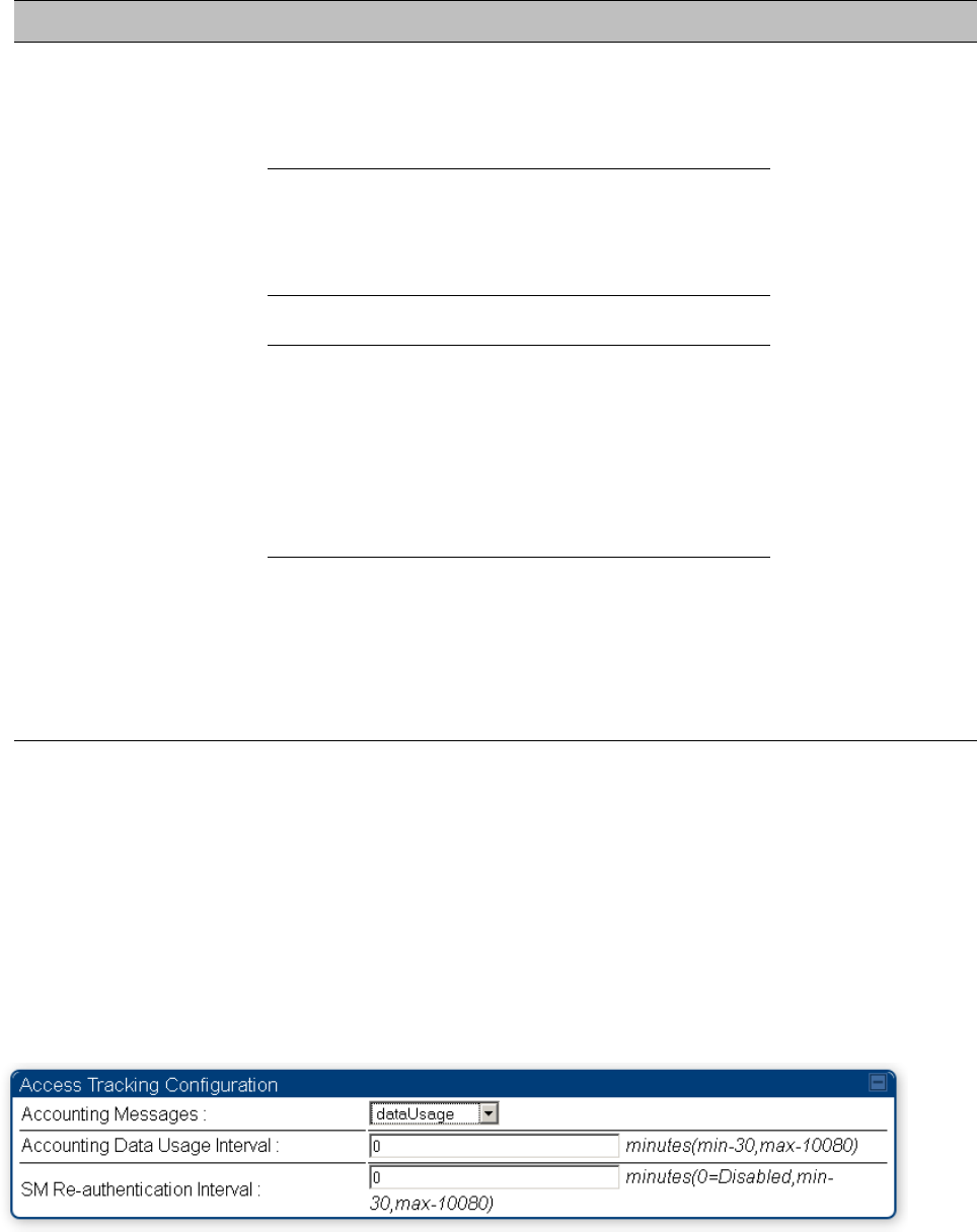
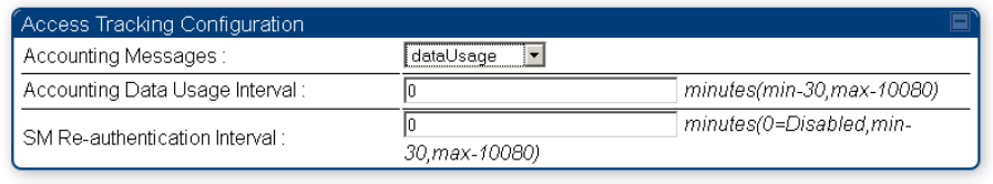
Accounting Messages
disable – no accounting messages are sent to the RADIUS server
deviceAccess – accounting messages are sent to the RADIUS server
regarding device access (see Table 176).
dataUsage – accounting messages are sent to the RADIUS server
regarding data usage (see Table 176).
Accounting Data
Usage Interval
The interval for which accounting data messages are sent from the radio
to the RADIUS server. If 0 is configured for this parameter, no data
usage messages are sent.
Chapter 7: Configuration Configuring a RADIUS server
Page 7-236
SM Re-authentication
Interval
The interval for which the SM will re-authenticate to the RADIUS server.
SM – Technician/Installer/Administrator
Authenti
c
ation
The centralized user name and password management for SM is same as AP. Follow AP –
Technician/Installer/Administrator Authentication on page 7-234 procedure.
Note
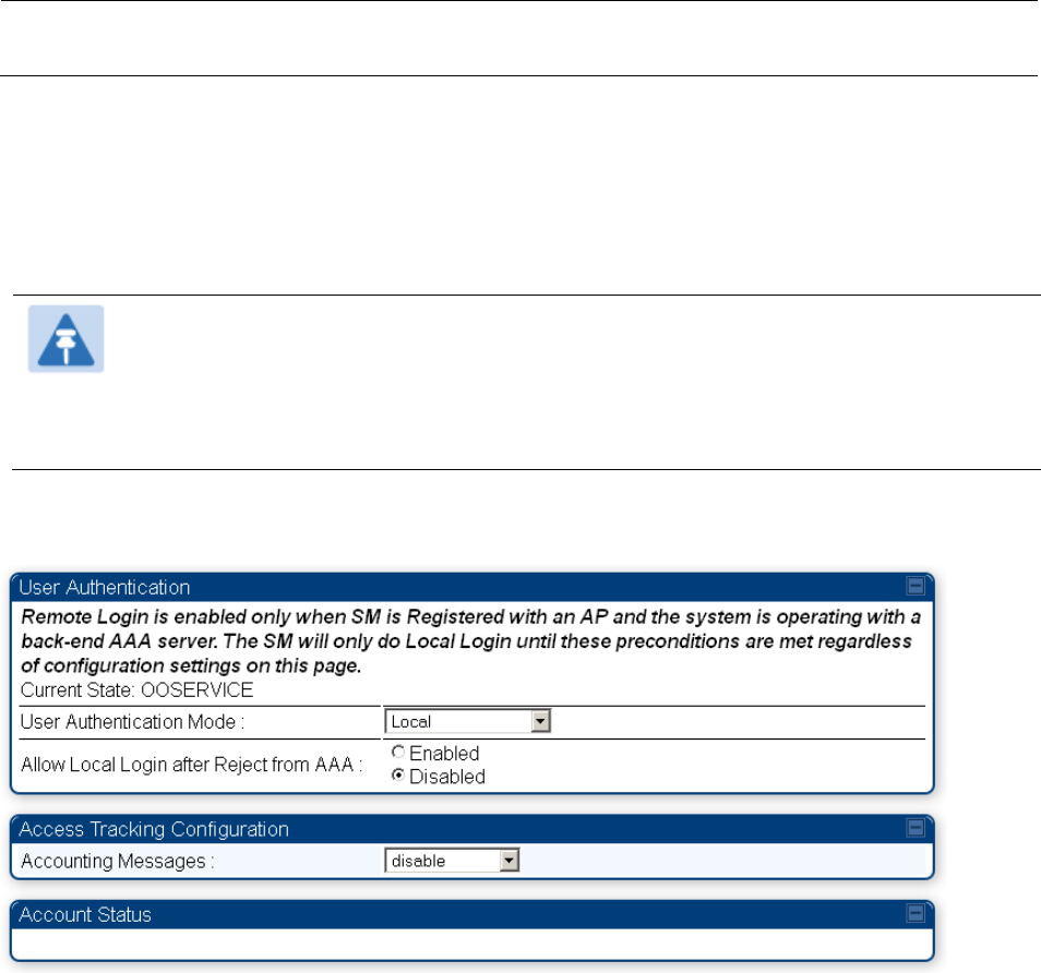
Remote access control is enabled only after the SM registers to an AP that has
Authentication Mode set to RADIUS AAA. Local access control will always be used
before registration and is used after registration if the AP is not configured for
RADIUS.
Figure 146 User Authentication and Access Tracking tab of the SM
Chapter 7: Configuration Configuring a RADIUS server
Page 7-237
Table 175 SM User Authentication and Access Tracking attributes
Attribute Meaning
User Authentication
Mode
Local: The local SM is checked for accounts. No centralized RADIUS
accounting (access control) is performed.
Remote: Authentication by the centralized RADIUS server is required
to gain access to the SM if the SM is registered to an AP that has
RADIUS AAA Authentication Mode selected. For up to 2 minutes a
test pattern is displayed until the server responds or times out.
Remote then Local: Authentication using the centralized RADIUS
server is attempted. If the server sends a reject message, then the
setting of Allow Local Login after Reject from AAA determines if the
local user database is checked or not. If the configured servers do
not respond within 2 minutes, then the local user database is used.
The successful login method is displayed in the navigation column
of the SM.
Allow Local Login
after Reject from
AAA
If a user authentication is rejected from the AAA server, the user is
allowed to login locally to the radio’s management interface. It is
applicable ONLY when the User Authentication Mode is set to “Remote
then Local”.
Note
When the radio User Authentication Mode is set to
“Local” or “Remote”, the Allow Local Login after Reject
from AAA does not any effect.
Accounting
Messages
disable – no accounting messages are sent to the RADIUS server
deviceAccess – accounting messages are sent to the RADIUS server
regarding device access (see Table 176).

Chapter 7: Configuration Configuring a RADIUS server
Page 7-238
Access
T
ra
c
kin
g
To track logon and logoff times on individual radios by technicians, installers,
and
administrators, on the AP or SM’s Account > User Authentication and Access Tracking tab
under
Accounting (Access Tracking) set Accounting Messages to “deviceAccess”.
Device Access Tracking is enabled separately from User Authentication Mode. A given AP
or
SM
can be configured for both, either, or
neither.
RADIUS Device Data Accounting
PMP 450 Platform systems include support for RADIUS accounting messages for usage-based
billing. This accounting includes indications for subscriber session establishment, subscriber
session disconnection, and bandwidth usage per session for each SM that connects to the AP. The
attributes included in the RADIUS accounting messages are shown in the table below.
Table 176 Device data accounting RADIUS attributes
Sender Message Attribute Value Description
AP Accounting-
Request
Acct-Status-Type 1 - Start This message is
sent every time a
SM registers with
an AP, and after
the SM stats are
cleared.
Acct-Session-Id
Unique per AP session.
Initial value is SM MAC, and
increments after every start
message sent of an in
session SM.
Event-Timestamp UTC time the event
occurred on the AP
AP Accounting-
Request
Acct-Status-Type 2 - Stop This message is
sent every time a
SM becomes
unregistered with
an AP, and when
the SM stats are
cleared.
Acct-Session-Id
Unique per AP session.
Initial value is SM MAC, and
increments after every start
message sent of an in
session SM.
Acct-Input-Octets
Sum of the input octets
received at the SM over
regular data VC and the
high priority data VC (if
enabled). Will not include
broadcast.
Acct-Output-Octets
Sum of the output octets
sent from the SM over
regular data VC and the
high priority data VC (if
enabled).

Chapter 7: Configuration Configuring a RADIUS server
Page 7-239
Sender Message Attribute Value Description
Acct-Input-
Gigawords
Number of times the Acct-
Input-Octets counter has
wrapped around 2^32 over
the course of the session
Acct-Output-
Gigawords
Number of times the Acct-
Output-Octets counter has
wrapped around 2^32 over
the course of the session
Acct-Input-Packets
Sum of unicast and
multicast packets that are
sent to a particular SM over
the regular data VC and the
high priority data VC (if
enabled). It will not include
broadcast.
Acct-Output-
Packets
Sum of unicast and
multicast packets that are
sent from a particular SM
over the regular data VC
and the high priority data
VC (if enabled).
Acct-Session-Time Uptime of the SM session.
Acct-Terminate-
Cause
Reason code for session
termination
AP Accounting-
Request
Acct-Status-Type 3 - Interim-Update This message is
sent periodically
per the operator
configuration on
the AP in seconds.
Interim update
counts are
cumulative over
the course of the
session
Acct-Session-Id
Unique per AP session.
Initial value is SM MAC, and
increments after every start
message sent of an in
session SM.
Acct-Input-Octets
Sum of the input octets sent
to the SM over regular data
VC and the high priority
data VC (if enabled). Will
not include broadcast.
Acct-Output-Octets
Sum of the output octets
set from the SM over
regular data VC and the
high priority data VC (if
enabled).
Chapter 7: Configuration Configuring a RADIUS server
Page 7-240
Sender Message Attribute Value Description
Acct-Input-
Gigawords
Number of times the Acct-
Input-Octets counter has
wrapped around 2^32 over
the course of the session
Acct-Output-
Gigawords
Number of times the Acct-
Output-Octets counter has
wrapped around 2^32 over
the course of the session
Acct-Session-Time Uptime of the SM session.
Acct-Input-Packets
Sum of unicast and
multicast packets that are
sent to a particular SM over
the regular data VC and the
high priority data VC (if
enabled). It will not include
broadcast.
Acct-Output-
Packets
Sum of unicast and
multicast packets that are
sent from a particular SM
over the regular data VC
and the high priority data
VC (if enabled).
The data accounting configuration is located on the AP’s Accounts > User Authentication and
Access Tracking GUI menu, and the AP’s Authentication Mode must be set to Radius AAA for the
menu to appear. The accounting may be configured via the AP GUI as shown in the figures below.
By default accounting messages are not sent and the operator has the choice of configuring to
send only Device Access accounting messages (when a user logs in or out of the radio), only Data
Usage messages, or both. When Data Accounting is enabled, the operator must specify the
interval of when the data accounting messages are sent (0 – disabled, or in the range of 30-10080
minutes). The default interval is 30 minutes.
Figure 147 RADIUS accounting messages configuration
Chapter 7: Configuration Configuring a RADIUS server
Page 7-241
The data accounting message data is based on the SM statistics that the AP maintains, and these
statistics may be cleared on the AP by an operator. If an operator clears these messages and data
accounting is enabled, an accounting stop message is sent followed by an accounting start
message to notify the AAA of the change.
If an operator clears the VC statistics on the device through the management GUI, a RADIUS stop
message and data start message is issued for each device affected. The start and stop messages
will only be sent once every 5 minutes, so if an operator clears these statistics multiple times
within 5 minutes, only one set of data stop/start messages is sent. This may result in inaccurate
data accumulation results.
RADIUS Device Re-authentication
PMP 450 Platform systems include support for periodic SM re-authentication in a network without
requiring the SM to re-register (and drop the session). The re-authentication may be configured to
occur in the range of every 30 minutes to weekly.
Figure 148 Device re-authentication configuration
The re-authentication interval is only configurable on the AP. When this feature is enabled, each
SM that enters the network will re-authenticate each the interval time has expired without
dropping the session. The response that the SM receives from the AAA server upon re-
authentication is one of the following:
Success: The SM continues normal operation
Reject: The SM de-registers and will attempt network entry again after 1 minute and then if
rejected will attempt re-entry every 15 minutes
Timeout or other error: The SM remains in session and attempt 5 times to re-authenticate with
the RADIUS-REQUEST message. If these attempts fail, then the SM will go out of session and
proceed to re-authenticate after 5 minutes, then every 15 minutes.
Although re-authentication is an independent feature, it was designed to work alongside with the
RADIUS data usage accounting messages. If a user is over their data usage limit the network
operator can reject the user from staying in the network. Operators may configure the RADIUS
‘Reply-Message’ attribute with an applicable message (i.e. “Data Usage Limit Reached”) that is
sent to the subscriber module and displayed on the general page.
Chapter 7: Configuration Configuring a RADIUS server
Page 7-242
RADIUS Change of Authorization and Disconnect Message
Prior to this feature, SM will get configuration parameters from a RADIUS server during
authentication process. This feature allows an administrator to control configuration parameters in
the SM while SM is in session. The configuration changes in SM are done using RADIUS Change
of Authorization method (RFC 3576) on the existing RADIUS authentication framework for AP and
SM. A typical use case could be changing the QOS parameters after a certain amount of
bandwidth usage by a SM.
Figure 149 RADIUS CoA configuration for AP
The RADIUS CoA feature enables initiating a bi-directional communication from the RADIUS
server(s) to the AP and SM.
The AP listens on UDP port 3799 and accepts CoA requests from the configured RADIUS servers.
This CoA request should contain SM MAC address in ‘User-Name’ attribute as identifier and all
other attributes which control the SM config parameters. For security reasons, a timestamp also
needs to be added as ‘Event-Timestamp’ attribute. Hence the time should also be synchronized
between the RADIUS server(s) and the AP to fit within a window of 300 seconds.
Once the configuration changes are applied on the SM, CoA-ACK message is sent back to RADIUS
server. If the validation fails, the AP sends a CoA-NACK response to the RADIUS server with proper
error code.
A Disconnect-Message is sent by the RADIUS server to NAS in order to terminate a user session
on a NAS and discard all associated session context. It is used when the authentication AAA server
wants to disconnect the user after the session has been accepted by the RADIUS.
In response of Disconnect-Request from RADIUS server, the NAS sends a Disconnect-ACK if all
associated session context is discarded, or a Disconnect-NACK, if the NAS is unable to disconnect
the session.
Note
The RADIUS CoA feature will only enabled if Authentication mode is set to RADIUS
AAA.
Chapter 7: Configuration Configuring a RADIUS server
Page 7-243
Microsoft RADIUS support
This feature allows to configure Microsoft RADIUS (Network Policy and Access Services a.k.a
NPS) as Authentication server for SM and User authentication.
For SM Authentication, SM will user PEAP-MSCHAPv2 since NPS doesn't
support
TTLS
protocol.
For User Authentication, the Canopy software will use EAP-MD5 but the user has to do certain
configuration in order to enable EAP-MD5 on NPS.
Note
All this configuration has been tested on Windows Server 2012 R2 version.
This feature is not supported on hardware board type P9 or lower platforms.
SM Authentication Configuration
There are no new configuration on AP. However SM has to be configured for PEAP authentication
protocol.
1. Go to Configuration > Security page
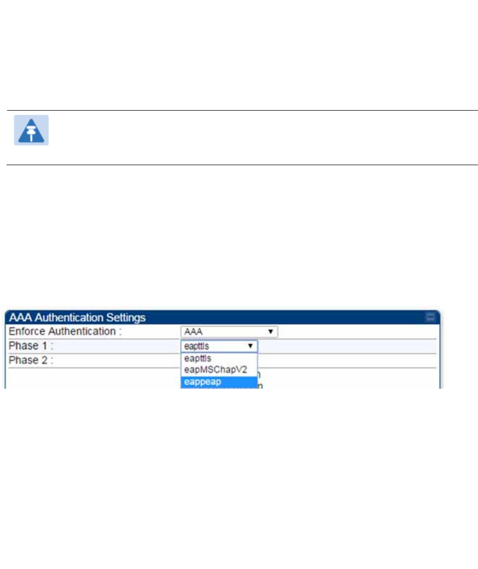
2. Select “eappeap” for Phase 1 attribute under tab AAA Authentication Settings.
Figure 150 EAPPEAP settings
The Phase 2 will change automatically to MSCHAPv2 on select of Phase 1 attribute as EAP-PEAP.
Other parameters of Phase 2 protocols like PAP/CHAP will be disabled.
Windows Server Configuration
Import Certificate
The SM certificate has to be imported to Windows Server for certificate authentication.
1. Copy the certificate which is configured in SM under Configuration > Security -> Certificate1
to Windows Server machine.
2. Right click and select 'Install Certificate'. This will install the certificate and it's ready for use.
This certificate will be used while configuring PEAP-MSCHAPv2 in NPS.
Chapter 7: Configuration Configuring a RADIUS server
Page 7-244
NPS Configuration (https://technet.microsoft.com/en-us/network/bb545879.aspx)
Following items should be configured in NPS Console:
RADIUS Client
o https://technet.microsoft.com/en-us/library/cc732929
Connection Request Policies
o https://technet.microsoft.com/en-us/library/cc730866
o Choose 'Wireless-Other' in NAS-Port-Type
Network Policy
o https://technet.microsoft.com/en-us/library/cc755309
o Choose 'Wireless-Other' in NAS-Port-Type.
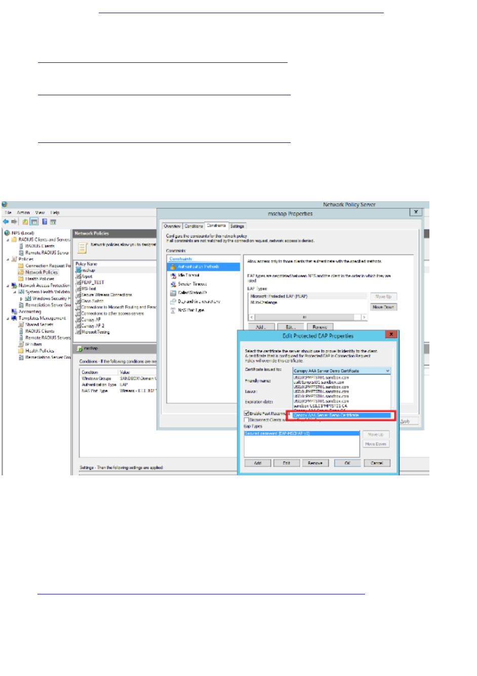
o While configuring PEAP, select the above imported certificate.
Figure 151 Importing certificate in NPS
User Authentication Configuration
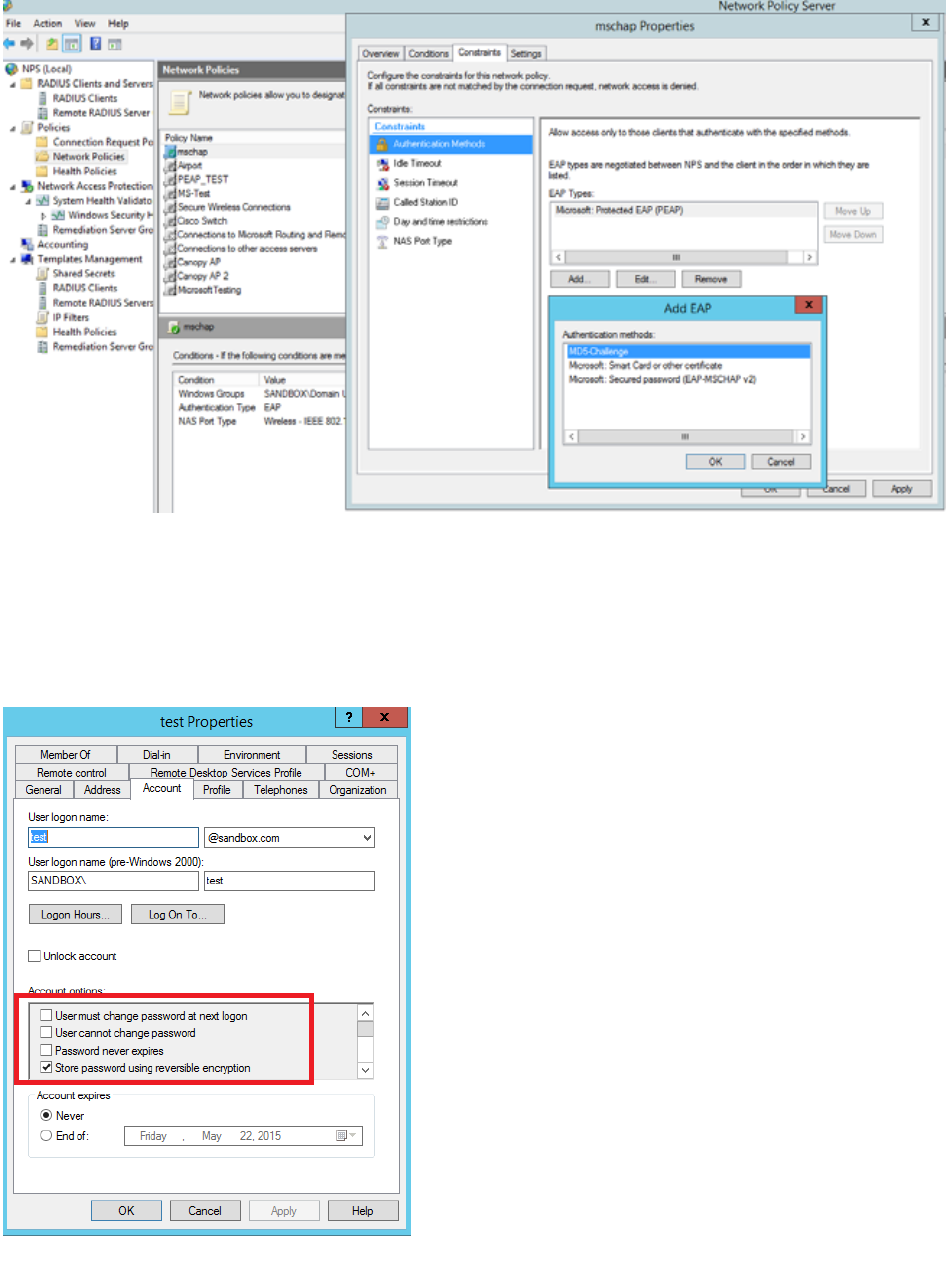
Enabling EAP-MD5
As mentioned earlier, Microsoft has deprecated the support for MD5 from versions of Windows.
To enable MD5, the following steps to be followed:
1. Follow the instructions:
https://support.microsoft.com/en-us/kb/922574/en-us?wa=wsignin1.0
Optionally, the registry file can be downloaded. It can be installed by double-click it in
Windows Registry.
2. From NPS Console Network Policy > <Policy Name> > Properties > Constrains >
Authentication Method and click Add. Select MD5 and click OK.
Chapter 7: Configuration Configuring a RADIUS server
Page 7-245
Figure 152 Selecting MD5 from NPS console
User Configuration in Active Directory
Next open 'Active Directory Users and Computers' and create user.
Make sure user property is configured as shown below.
Figure 153 User configuration
Chapter 7: Configuration Configuring a RADIUS server
Page 7-246
RADIUS VSA Configuration
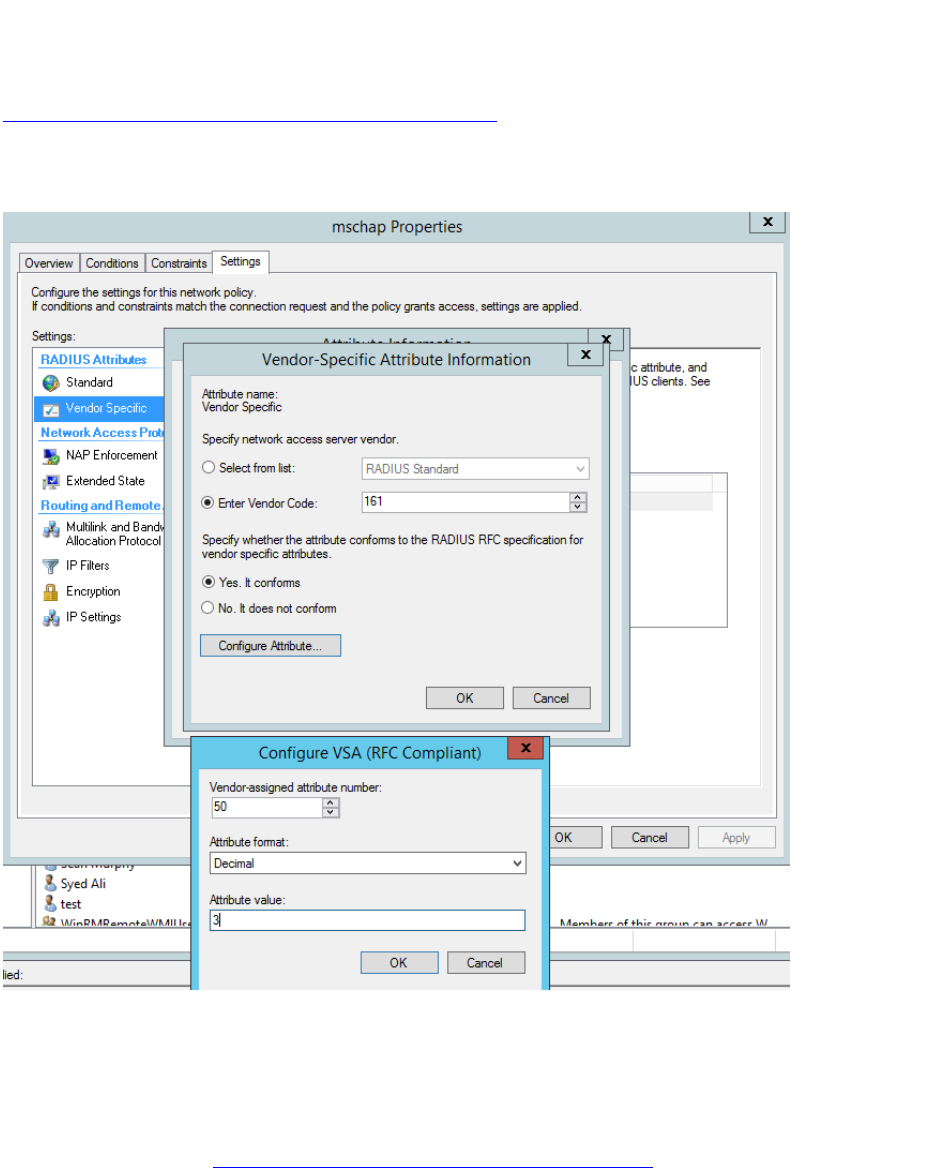
Before using VSA, the Cambium-Canopy-UserLevel(50) VSA must be configured with some access
level say ADMIN(3).
Follow below link for configuring VSA:
https://technet.microsoft.com/en-us/library/cc731611
The Cambium’s vendor code is 161.
Figure 154 RADIUS VSA configuration
Accounting
User can enable accounting in NPS under NPS Console > Accounting >
Configure Accounting.
For more details refer https://technet.microsoft.com/library/dd197475
Chapter 7: Configuration Configuring a RADIUS server
Page 7-247
Cisco ACS RADIUS Server Support
This briefly explains how to configure CIsco ACS RADIUS server for PEAP-MSCHAPv2
authentication.
The configuration had been tested on CISCO ACS Version : 5.7.0.15
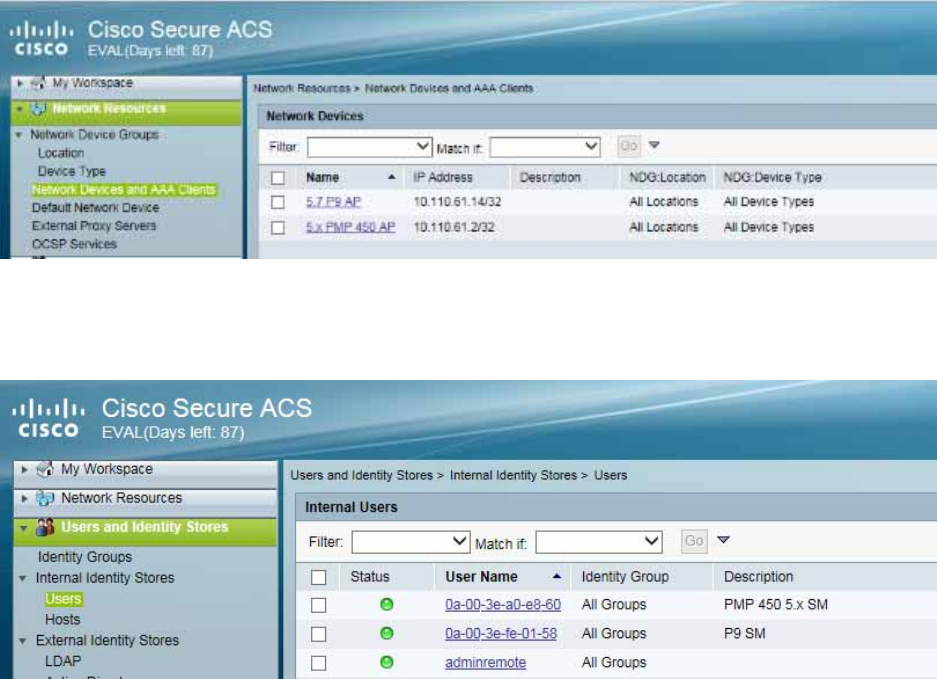
Adding RADIUS client
Figure 155 Adding RADIUS client
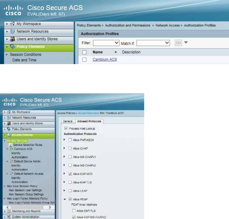
Creating Users
Figure 156 Creating users
Chapter 7: Configuration Configuring a RADIUS server
Page 7-248
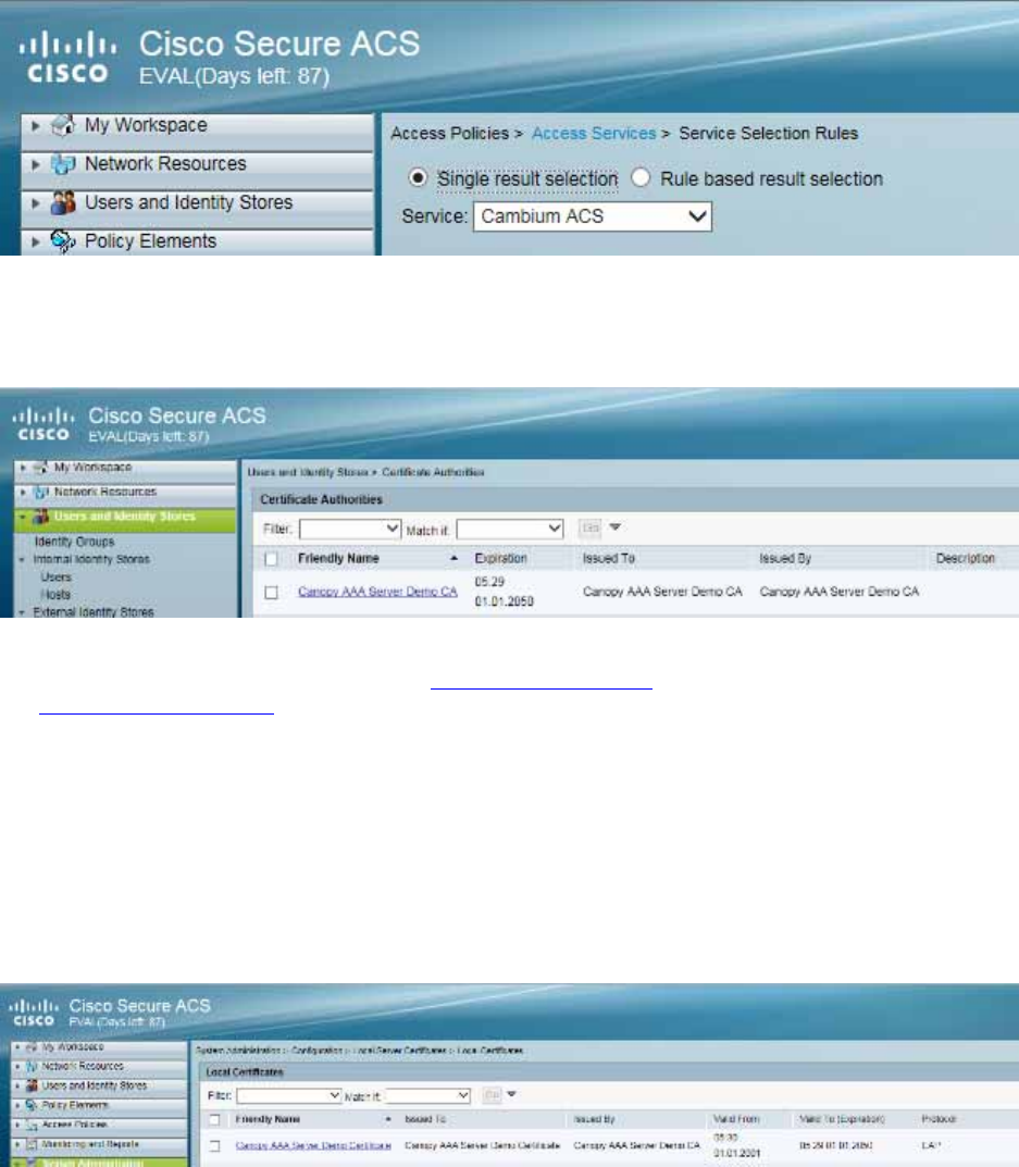
Creating RADIUS instance
Figure 157 Creating RADIUS instance
RADIUS protocols
Figure 158 RADIUS protocols
Chapter 7: Configuration Configuring a RADIUS server
Page 7-249
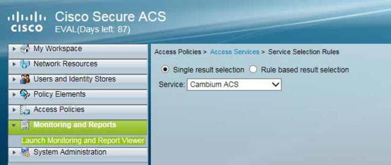
Service selection
Figure 159 Service selection
Adding Trusted CA
Figure 160 Adding Trusted CA
Note that certificate has to be in DER form, so if you have in PEM format convert using openssl.
openssl.exe x509 -in <path-to->/cacert_aaasvr.pem -outform DER -out <path-
to>/cacert_aaasvr.der
Installing Server Certificate
After installing trusted CA, you need to add a server certificate which will be used for TLS tunnel.
Generally you have to install same certificate which is installed in your AP, so that AP can trust the
radius server.
Figure 161 Installing Server Certificate
Chapter 7: Configuration Configuring a RADIUS server
Page 7-250
Monitoring Logs
Figure 162 Monitoring logs
Configuring VSA
Before using VSA , user has to add Cambium Vendor Specific Attribute
Navigate to System Administration > Configuration > Dictionaries > Protocols > RADIUS > RADIUS
VSA > Motorola
If Motorola is not present you can create Vendor with ID 161 and add all the VSA one by one.
Chapter 7: Configuration Configuring a RADIUS server
Page 7-251
Figure 163 VSA list
Using VSA for users
Navigate to Access Policies > Access Services > Cambium ACS > Authorization
1. Change condition to User name
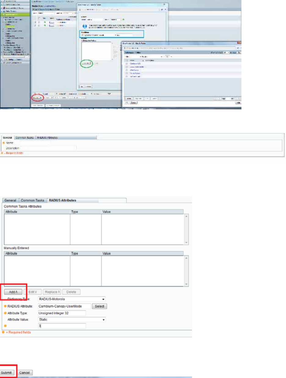
Chapter 7: Configuration Configuring a RADIUS server
Page 7-252
2. Next click Create and then click Select see diagram below
3. Click Create from the screen you get following screen
Chose some name and then move to RADIUS Attributes tab
4. Fill attribute which all you want for that particular user
Important: Click Add for each attribute and when done click Submit.
Chapter 7: Configuration Configuring a RADIUS server
Page 7-253
5. Now you are ready to use this Authorization profile for the use
Select and Press OK
6. Finally press Save Changes and you are ready to use it.

Page 8-1
Chapter 8: Tools
The AP and SM GUIs provide several tools to analyze the operating environment, system
performance and networking, including:
Using Spectrum Analyzer tool on page 8-2
Using the Alignment Tool on page 8-15
Using the Link Capacity Test tool on page 8-21
Using AP Evaluation tool on page 8-31
Using BHM Evaluation tool on page 8-35
Using the OFDM Frame Calculator tool on page 8-39
Using the Subscriber Configuration tool on page 8-44
Using the Link Status tool on page 8-45
Using BER Results tool on page 8-50
Using the Sessions tool on page 8-51
Chapter 8: Tools Using Spectrum Analyzer tool
Page 8-2
Using Spectrum Analyzer tool
The integrated spectrum analyzer can be very useful as a tool for troubleshooting and RF planning,
but is not intended to replicate the accuracy and programmability of a high-end spectrum analyzer,
which sometime can be used for other purposes.
The AP/BHM and SM/BHS perform spectrum analysis together in the Sector Spectrum Analyzer
tool.
Caution
On start of the Spectrum Analyzer on a module, it enters a scan mode and drops any
RF connection it may have had. When choosing Start Timed Spectrum Analysis, the
scan is run for the amount of time specified in the Duration configuration parameter.
When choosing Start Continuous Spectrum Analysis, the scan is run continuously for
24 hours, or until stopped manually (using the Stop Spectrum Analysis button).
Any module can be used to see the frequency and power level of any detectable signal that is
within, just above, or just below the frequency band range of the module.
Note
Vary the days and times when you analyze the spectrum in an area. The RF
environment can change throughout the day or throughout the week.
Mapping RF Neighbor Frequencies
The neighbor frequencies can be analyzed using Spectrum Analyzer tool. Following modules allow
user to:
Use a BHS or BHM for PTP and SM or AP for PMP as a Spectrum Analyzer.
View a graphical display that shows power level in RSSI and dBm at 5 MHz increments
throughout the frequency band range, regardless of limited selections in the Custom Radio
Frequency Scan Selection List parameter of the SM/BHS.
Select an AP/BHM channel that minimizes interference from other RF equipment.
Caution
The following procedure causes the SM/BHS to drop any active RF link. If a link is
dropped when the spectrum analysis begins, the link can be re-established when
either a 15 minute interval has elapsed or the spectrum analyzer feature is disabled.
Chapter 8: Tools Using Spectrum Analyzer tool
Page 8-3
Temporarily deploy a SM/BHS for each frequency band range that need to monitor and access the
Spectrum Analyzer tab in the Tools web page of the module.
Using Spectrum Analyzer tool
Using the Remote Spectrum Analyzer tool
Spectrum Analyzer tool
Analyzing the spectrum
To use the built-in spectrum analyzer functionality of the AP/SM/BH, proceed as follows:
Procedure 29 Analyzing the spectrum
1 Predetermine a power source and interface that works for the AP/SM/BH in the
area to be analyzed.
2 Take the AP/SM/BH, power source and interface device to the area.
3 Access the Tools web page of the AP/SM/BH.
4 Enter Duration in Timed Spectrum Analyzer Tab. Default value is 10 Seconds
5 Click Start Timed Sector Spectrum Analysis
6 The results are displayed:
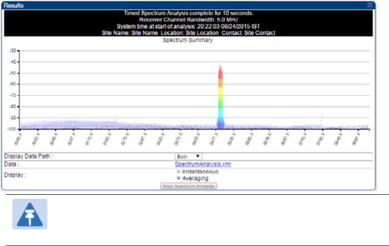
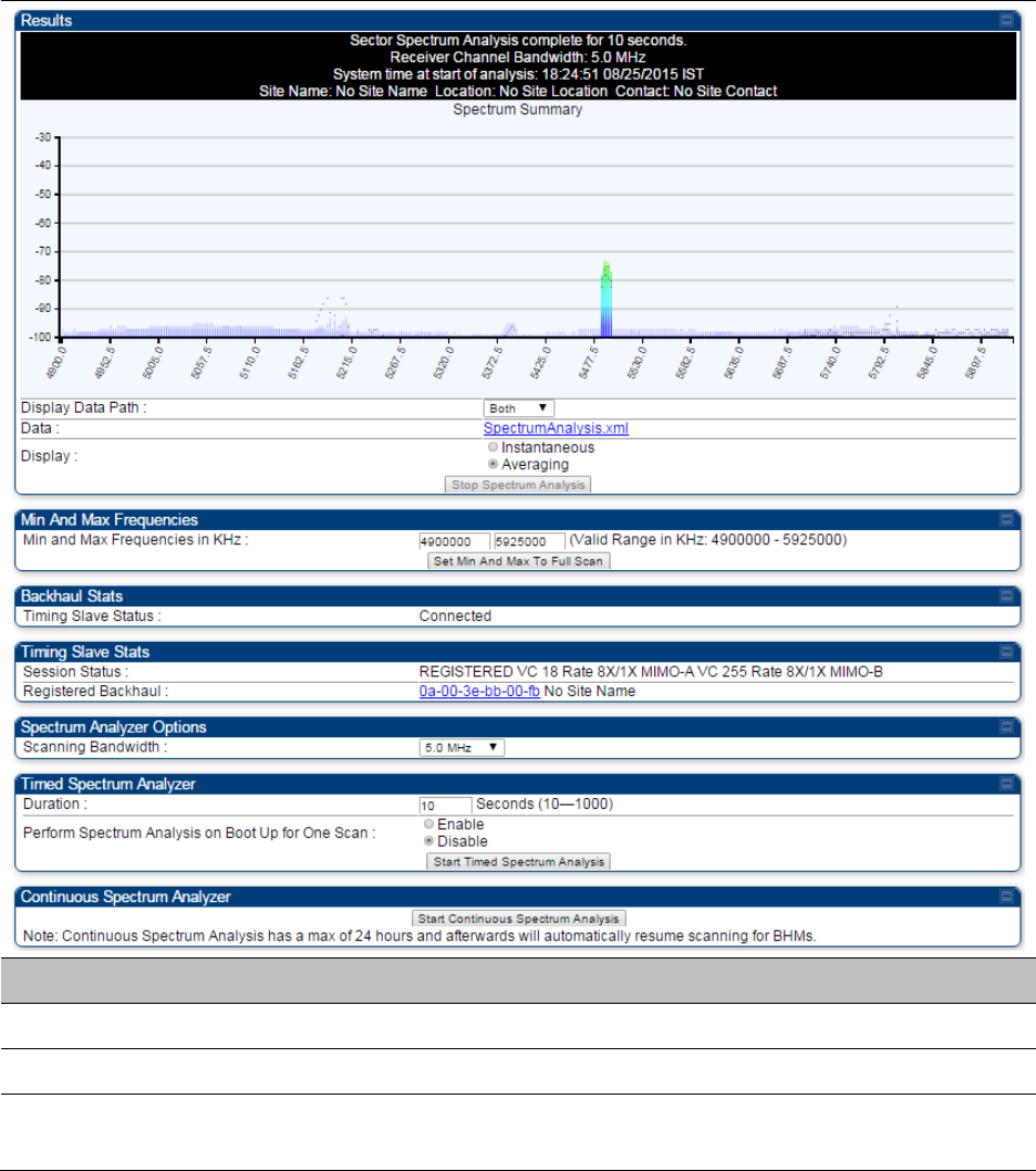
Figure 164 Spectrum analysis - Results
Note
AP/SM/BH scans for extra 40 seconds in addition to configured
Duration
7 Travel to another location in the area to BHS.
8 Click Start Timed Spectrum Analysis

Chapter 8: Tools Using Spectrum Analyzer tool
Page 8-4
9 Repeat Steps 4 and 6 until the area has been adequately scanned and logged.
As with any other data that pertains to your business, a decision today to put the data into a
retrievable database may grow in value to you over time.
Note
Wherever the operator find the measured noise level is greater than the sensitivity of
the radio that is plan to deploy, use the noise level (rather than the link budget) for
your link feasibility calculations.
The AP/SM/BH perform spectrum analysis together in the Sector Spectrum Analyzer
feature.
Graphical spectrum analyzer display
The AP/SM/BH display the graphical spectrum analyzer. An example of the Spectrum Analyzer
page is shown in Figure 164.
The navigation feature includes:
Results may be panned left and right through the scanned spectrum by clicking and dragging
the graph left and right
Results may be zoomed in and out using mouse
When the mouse is positioned over a bar, the receive power level, frequency, maximum and mean
receive power levels are displayed above the graph
To keep the displayed data current, either set “Auto Refresh” on the module’s Configuration >
General.
Spectrum Analyzer page of AP
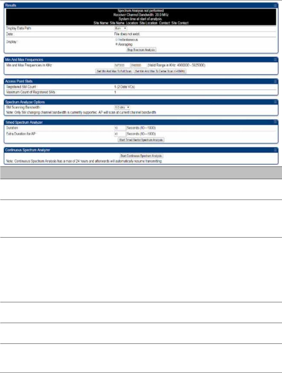
The Spectrum Analyzer page of AP is explained in Table 177.
Chapter 8: Tools Using Spectrum Analyzer tool
Page 8-5
Table 177 Spectrum Analyzer page attributes - AP
Attribute Meaning
Display Data Path Both means that the vertical and horizontal paths are displayed or an
individual path may be selected to display only a single-path reading.
Data For ease of parsing data and to facilitate automation, the spectrum
analyzer results may be saved as an XML file. To save the results in an
XML formatted file, right-click the “SpectrumAnalysis.xml” link and save
the file.
Display Instantaneous means that each reading (vertical bar) is displayed with
two horizontal lines above it representing the max power level received
(top horizontal line) and the average power level received (lower
horizontal line) at that frequency.
Averaging means that each reading (vertical bar) is displayed with an
associated horizontal line above it representing the max power level
received at that frequency.
Min and Max
Frequencies in KHz
Enter minimum and maximum frequencies to be scanned.
Set Min And Max to
Full Scan
On the button press, it sets mimimum and maximum allowed
frequencies for scanning.
Set Min And Max to
Center Scan +/-40
MHz
On the button press, it sets mimium and maximum frequencies to ± 40
MHz of center frequency for scanning.

Chapter 8: Tools Using Spectrum Analyzer tool
Page 8-6
Registered SM Count This field displays the MAC address and Site Name of the registered SM.
Maximum Count of
Registered SMs
This field displays the maximum number of registered SMs.
SM Scanning
Bandwidth
This field allows to select SM’s scanning bandwidth.
Duration This field allows operators to configure a specified time for which the
spectrum is scanned. If the entire spectrum is scanned prior to the end of
the configured duration, the analyzer will restart at the beginning of the
spectrum.
Continuous
Spectrum Analyzer
Start Continuous Spectrum Analysis button ensures that when the SM is
powered on, it automatically scans the spectrum for 10 seconds. These
results may then be accessed via the Tools > Spectrum Analyzer GUI
page.
Spectrum Analyzer page of SM
The Spectrum Analyzer page of SM is explained in Table 178.
Note
Spectrum Analyzer is not currently supported by 450m.
Chapter 8: Tools Using Spectrum Analyzer tool
Page 8-7
Table 178 Spectrum Analyzer page attributes - SM
Attribute Meaning
Display Data Path Refer Table 177 on page 8-5
Data Refer Table 177 on page 8-5
Display Refer Table 177 on page 8-5
Min and Max
Frequencies in KHz
To scan min to max range of frequencies, enter min and max
frequencies in KHz and press Set Min and Max to Full Scan button.
To scan +/- 40 MHz from center frequency, enter center frequency in KHz
and press Set Min And Max To Center Scan +/- 40KHz button.
Registered SM Count Refer Table 177 on page 8-5
Maximum Count to
Registered SMs
Refer Table 177 on page 8-5
Duration Refer Table 177 on page 8-5
Chapter 8: Tools Using Spectrum Analyzer tool
Page 8-8
Spectrum Analyzer page of BHM
The Spectrum Analyzer page of BHM is explained in Table 179.
Table 179 Spectrum Analyzer page attributes - BHM
Attribute Meaning
Data Refer Table 177 on page 8-5
Display Refer Table 177 on page 8-5
Duration Refer Table 177 on page 8-5
Continuous
Spectrum Analyzer
Refer Table 177 on page 8-5
Chapter 8: Tools Using Spectrum Analyzer tool
Page 8-9
Spectrum Analyzer page of BHS
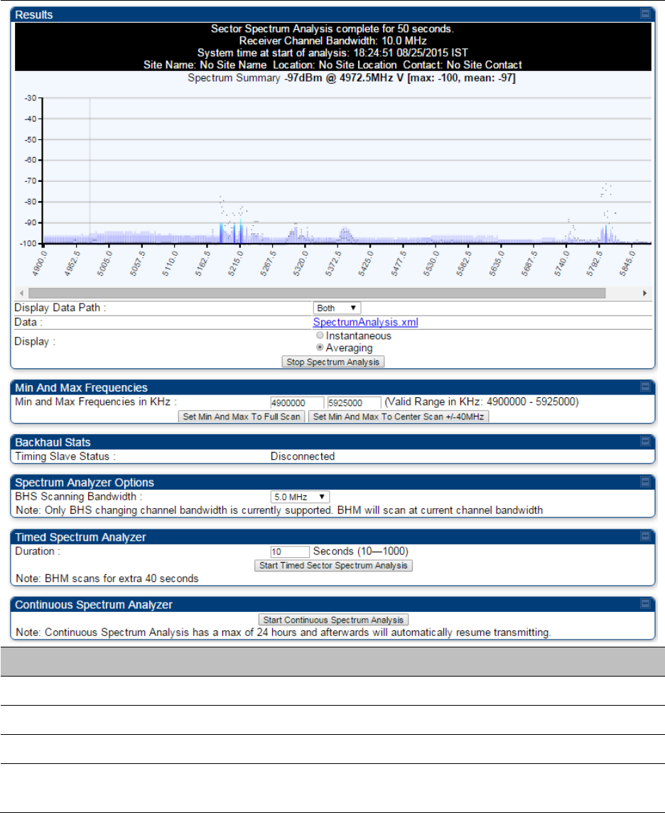
The Spectrum Analyzer page of BHS is explained in Table 180.
Table 180 Spectrum Analyzer page attributes - BHS
Attribute Meaning
Data Refer Table 177 on page 8-5
Display Refer Table 177 on page 8-5
Session Status This field displays current session status and rates. The session states
can be Scanning, Syncing, Registering or Registered.

Chapter 8: Tools Using Spectrum Analyzer tool
Page 8-10
Registered Backhaul This field displays MAC address of BHM and PTP model number
Duration Refer Table 177 on page 8-5
Perform Spectrum
Analysis on Boot Up
for one scan
This field allows to Enable or Disable to start Spectrum Analysis on boot
up of module for one scan.
Continuous
Spectrum Analyzer
Refer Table 177 on page 8-5
Chapter 8: Tools Using Spectrum Analyzer tool
Page 8-11
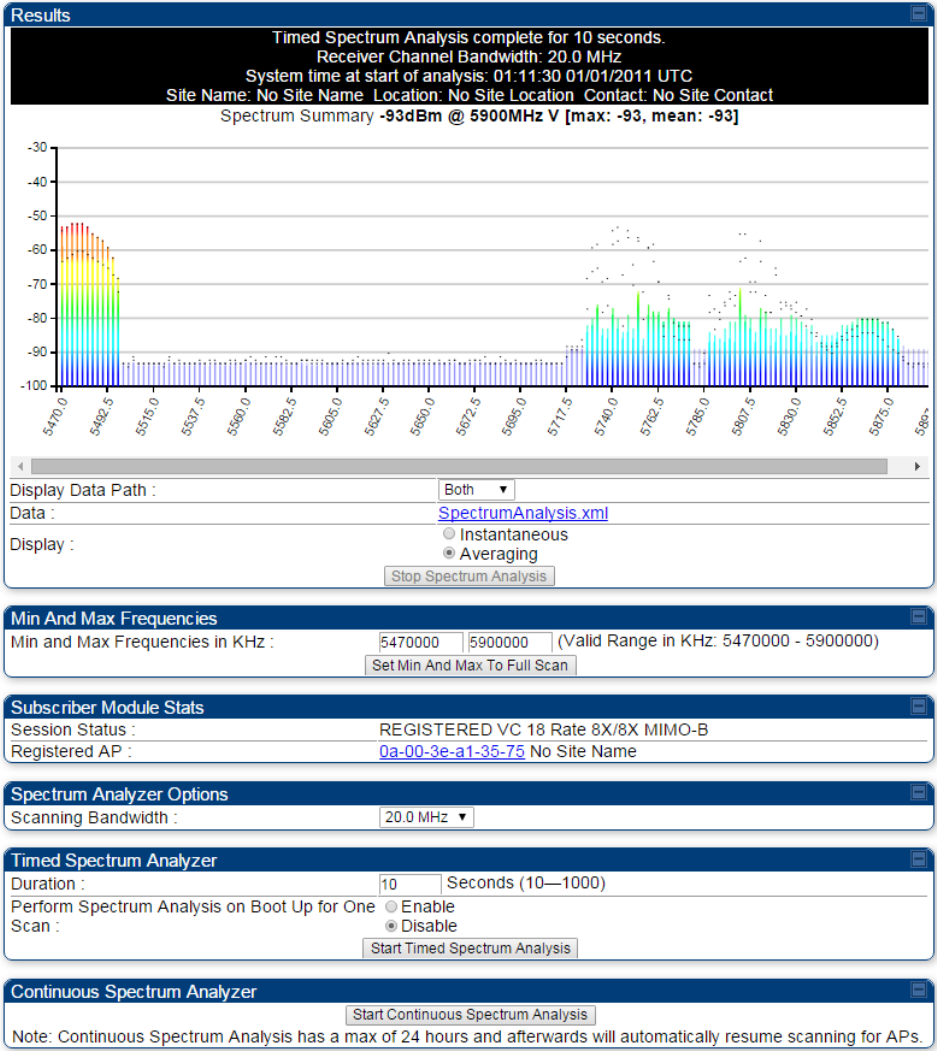
Spectrum Analyzer page result of PMP 450 SM
Figure 165 Spectrum Analyzer page result – PMP 450 SM
Chapter 8: Tools Using Spectrum Analyzer tool
Page 8-12
Remote Spectrum Analyzer tool
The Remote Spectrum Analyzer tool in the AP/BHM provides additional flexibility in the use of the
spectrum analyzer in the SM/BHS. Set the duration of 10 to 1000 seconds, then click the Start
Remote Spectrum Analysis button to launch the analysis from that SM/BHS.
In PMP configuration, a SM has to be selected from the drop-down list before launching Start
Remote Spectrum Analysis.
Analyzing the spectrum remotely
Procedure 30 Remote Spectrum Analyzer procedure
1 The AP/BHM de-registers the target SM/BHS.
2 The SM/BHS scans (for the duration set in the AP/BHM tool) to collect data for the
bar graph.
3 The SM/BHS re-registers to the AP/BHM.
4 The AP/BHM displays the bar graph.
The bar graph is an HTML file, but can be changed to an XML file, which is then easy to analyze
through the use of scripts that you may write for parsing the data. To transform the file to XML,
click the “SpectrumAnalysis.xml” link below the spectrum results. Although the resulting display
appears mostly unchanged, the bar graph is now coded in XML. You can now right-click on the bar
graph for a Save Target As option to save the Spectrum Analysis.xml file.
Remote Spectrum Analyzer page of AP
The Remote Spectrum Analyzer page of AP is explained in Table 181.
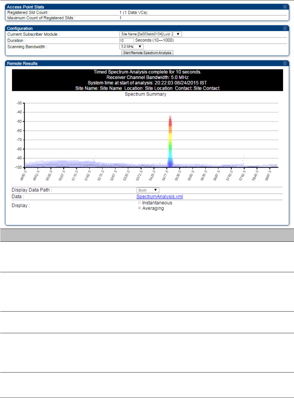
Chapter 8: Tools Using Spectrum Analyzer tool
Page 8-13
Table 181 Remote Spectrum Analyzer attributes - AP
Attribute Meaning
Registered SM Count This field displays the number of SMs that were registered to the AP
before the SA was started. This helps the user know all the SMs re-
registered after performing a SA.
Maximum Count of
Registered SMs
This field displays the largest number of SMs that have been
simultaneously registered in the AP since it was last rebooted. This
count can provide some insight into sector history and provide
comparison between current and maximum SM counts at a glance.
Current Subscriber
Module
The SM with which the Link Capacity Test is run.
Duration This field allows operators to configure a specified time for which the
spectrum is scanned. If the entire spectrum is scanned prior to the end of
the configured duration, the analyzer will restart at the beginning of the
spectrum.
Scanning Bandwidth This parameter defines the size of the channel scanned when running
the analyzer.
Chapter 8: Tools Using Spectrum Analyzer tool
Page 8-14
Remote Spectrum Analyzer page of BHM
The Remote Spectrum Analyzer page of BHM is explained in Table 182.
Table 182 Remote Spectrum Analyzer attributes - BHM
Attribute Meaning
Duration Refer Table 177 on page 8-5
Chapter 8: Tools Using the Alignment Tool
Page 8-15
Using the Alignment Tool
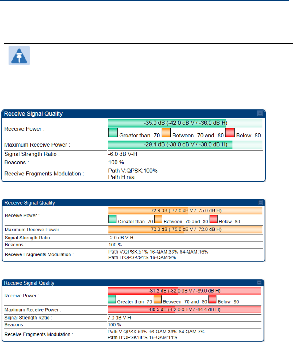
The SM’s or BHS’s Alignment Tool may be used to maximize Receive Power Level, Signal Strength
Ratio and Signal to Noise Ratio to ensure a stable link. The Tool provides color coded readings to
facilitate in judging link quality.
Note
To get best performance of the link, the user has to ensure the maximum Receive
Power Level during alignment by pointing correctly. The proper alignment is
important to prevent interference in other cells. The achieving Receive Power Level
green (>- 70 dBm) is not sufficient for the link.
Figure 166 Alignment Tool tab of SM – Receive Power Level > -70 dBm
Figure 167 Alignment Tool tab of SM – Receive Power Level between -70 to -80 dBm
Figure 168 Alignment Tool tab of SM – Receive Power Level < -80 dBm

Chapter 8: Tools Using the Alignment Tool
Page 8-16
Aiming page and Diagnostic LED – SM/BHS
The SM’s/BHS’s Alignment Tool (located in GUI Tools -> Aiming) may be used to configure the
SM’s/BHS’s LED panel to indicate received signal strength and to display decoded beacon
information/power levels. The SM/BHS LEDs provide different status based on the mode of the
SM/BHS. A SM/BHS in “operating” mode will register and pass traffic normally. A SM/BHS in
“aiming” mode will not register or pass traffic, but will display (via LED panel) the strength of
received radio signals (based on radio channel selected via Tools ->Aiming). See SM/BHS LEDs on
page 2-14.
Note
In order for accurate power level readings to be displayed, traffic must be present on
the radio link.
Refer Table 19 SM/BHS LED descriptions on page 2-15 for SM/BHS LED details.
Aiming page of SM
The Aiming page is similar to Spectrum Analyzer where it scans the spectrum but it does not
establish any session with any Aps. It has two modes – Single Frequency Only and Normal
Frequency Scan List.
The Aiming page of SM is explained in Table 183.
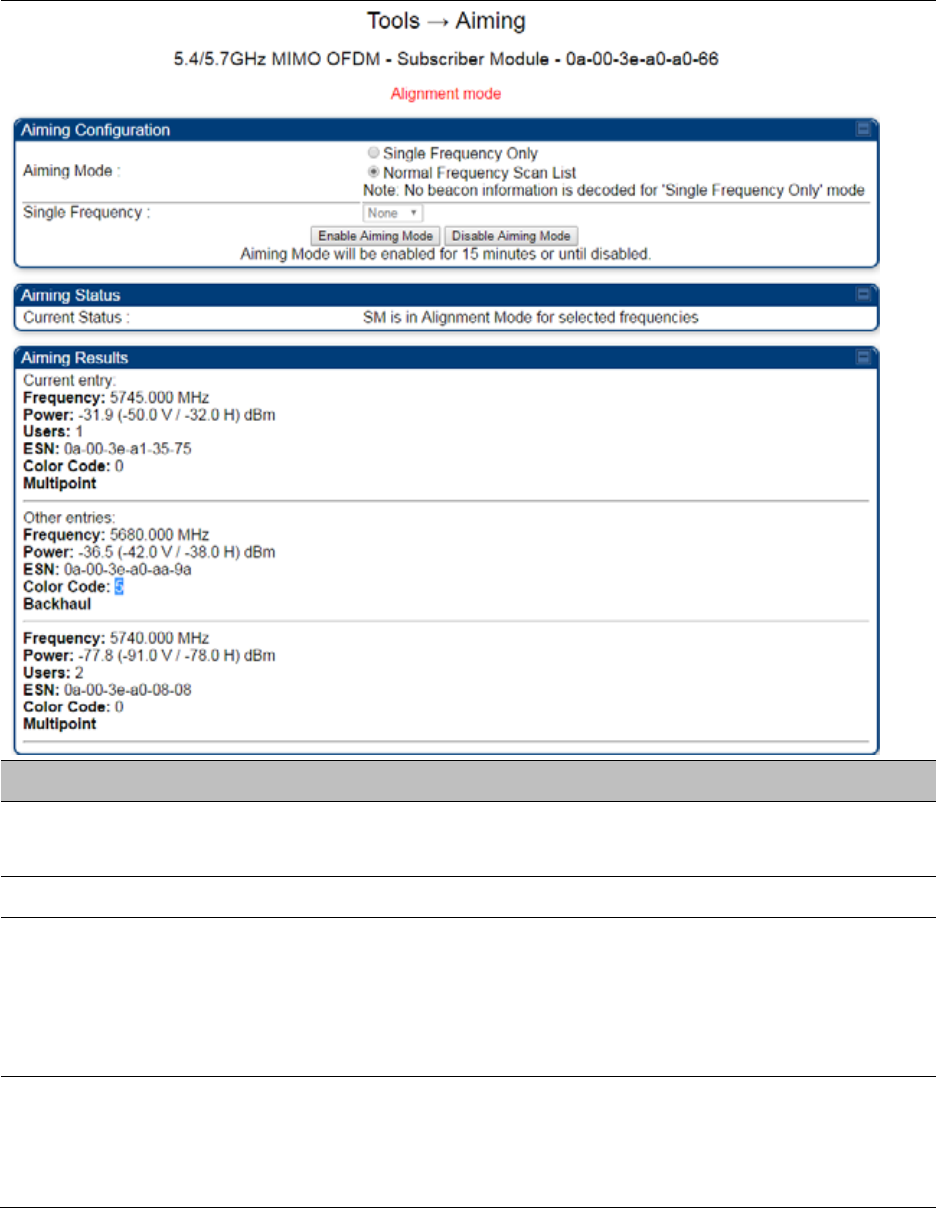
Chapter 8: Tools Using the Alignment Tool
Page 8-17
Table 183 Aiming page attributes – SM
Attribute Meaning
Aiming Mode Single Frequency Only: scans only selected single frequency.
Normal Frequency Scan List: scans: scans all frequency of scan list.
Single Frequency Select a particular frequency from drop down menu for scanning.
Scan Radio
Frequency Only
Mode
Enabled: the radio is configured to “aiming” or “alignment” mode,
wherein the LED panel displays an indication of receive power level. See
Table 19 SM/BHS LED descriptions on page 2-15.
Disabled: the radio is configured to “operating” mode, wherein the SM
registers and passes traffic normally.
Aiming Results The Aiming Results are displayed in two sections – Current entry and
Other entries.
Frequency: this field indicates the frequency of the AP which is
transmitting the beacon information.

Chapter 8: Tools Using the Alignment Tool
Page 8-18
Power: This field indicates the current receive power level (vertical
channel) for the frequency configured in parameter Radio Frequency.
Users: This field indicates the number of SMs currently registered to the
AP which is transmitting the beacon information.
ESN: This field indicates the MAC, or hardware address of the AP/BHM
which is transmitting the beacon information.
Color Code: This field displays a value from 0 to 254 indicating the AP’s
configured color code. For registration to occur, the color code of the SM
and the AP must match. Color code is not a security feature. Instead,
color code is a management feature, typically for assigning each sector a
different color code.
Color code allows you to force a SM to register to only a specific AP,
even where the SM can communicate with multiple APs. The default
setting for the color code value is 0. This value matches only the color
code of 0 (not all 255 color codes).
Multipoint or Backhaul: this field indicates type of configuration - point-
Multipoint(PMP) or Backhaul (PTP).
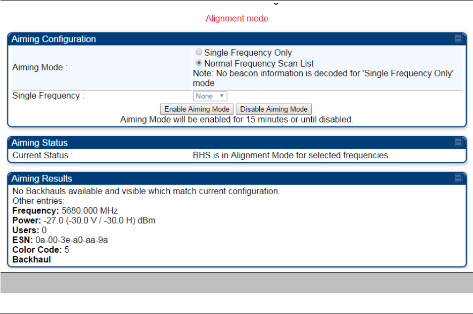
Chapter 8: Tools Using the Alignment Tool
Page 8-19
Aiming page of BHS
The Alignment page of BHS is explained in Table 184.
Table 184 Aiming page attributes - BHS
Attribute Meaning
Refer Table 161 for Atributes details.
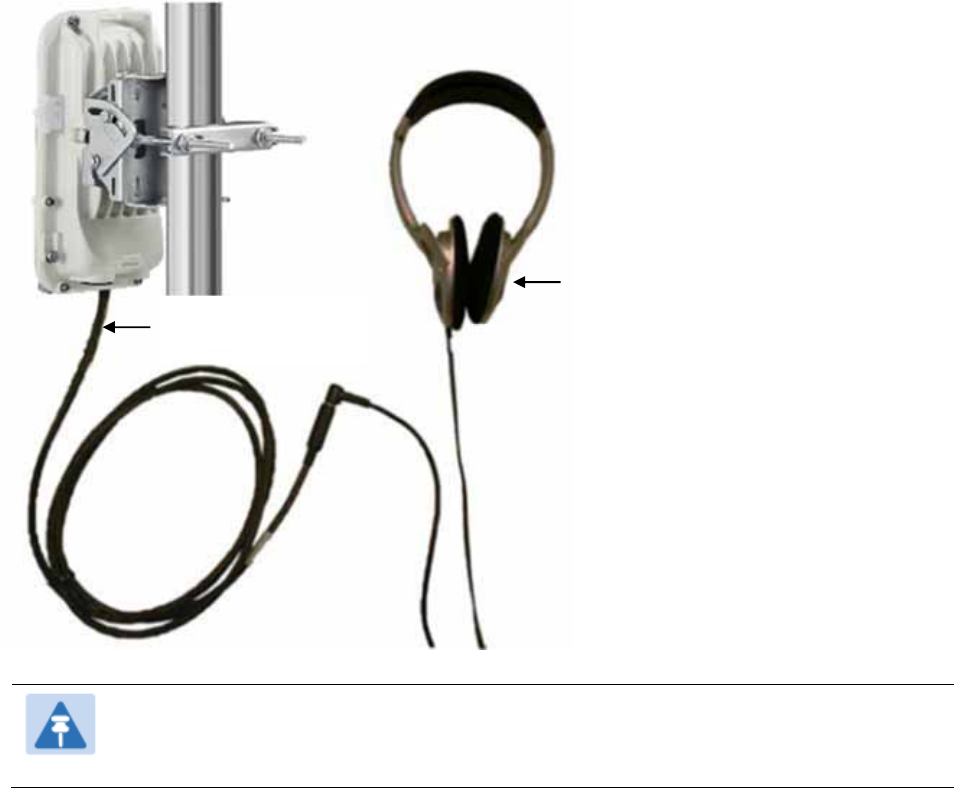
Chapter 8: Tools Using the Alignment Tool
Page 8-20
Alignment Tone
For coarse alignment of the SM/BHS, use the Alignment Tool located at Tools -> Alignment Tool.
Optionally, connect a headset alignment tone kit to the AUX/SYNC port of the SM/BHS and listen
to the alignment tone, which indicates greater SM/BHS receive signal power by pitch. By adjusting
the SM’s/BHS’s position until the highest frequency pitch is obtained operators and installers can
be confident that the SM/BHS is properly positioned. For information on device GUI tools available
for alignment, see sections Aiming page and Diagnostic LED – SM/BHS on page 8-16, Using the
Link Capacity Test tool on page 8-21 and Using AP Evaluation tool on page 8-31.
Figure 169 PMP/PTP 450i Series link alignment tone
Note
The Alignment Tone cable for a 450i Series uses an RJ-45 to headset cable where as
the 450 Series alignment tone cable uses an RJ-12 to headset cable.
Headphones
450i Alignment
tone adapter

Chapter 8: Tools Using the Link Capacity Test tool
Page 8-21
Using the Link Capacity Test tool
The Link Capacity Test tab allows you to measure the throughput and efficiency of the RF link
between two modules. Many factors, including packet length, affect throughput.
The Link Capacity Test tool has following modes:
Link Test with Multiple VCs: Tests radio-to-radio communication across selected or all
registered VCs, but does not bridge traffic (PMP 450m Series AP only).
Link Test without Bridging: Tests radio-to-radio communication, but does not bridge traffic.
Link Test with Bridging: Bridges traffic to “simulated” Ethernet ports, providing a status of the
bridged link.
Link Test with Bridging and MIR: Bridges the traffic during test and also adheres to any MIR
(Maximum Information Rate) settings for the link.
Extrapolated Link Test: Estimates the link capacity by sending few packets and measuring link
quality.
The Link Capacity Test tab contains the settable parameter Packet Length with a range of 64 to
1714 bytes. This allows you to compare throughput levels that result from various packet sizes.
The Current Results Status also displayed date and time of last performed Link Capacity Test. If
there is any change in time zone, the date and time will be adjusted accordingly.
Note
The Extrapolated Link Test can be run by Read-Only login also.
Performing Link Test
The link test is a tool that allows the user to test the performance of the RF link. Packets are added
to one or more queues in the AP in order to fill the frame. Throughput and efficiency are then
calculated during the test. The 450 and 450i APs offer link test options to one SM at a time. The
450m AP offers the option of a link test to multiple VCs at the same time. This allows the user to
test throughput in MU-MIMO mode, in which multiple SMs are served at the same time.
This new link test can be found under Tools > Link Capacity Test
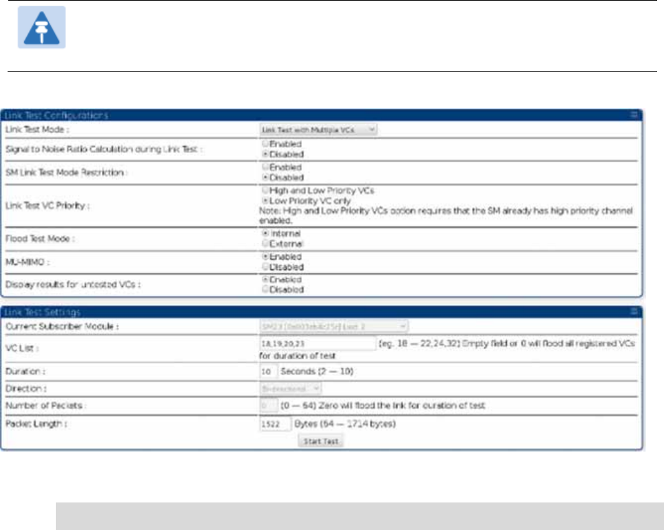
Chapter 8: Tools Using the Link Capacity Test tool
Page 8-22
Link Test with Multiple VCs
Note
The “Link Test with Multiple VCs” Link Capacity Test is supported for PMP 450m
Series AP only.
Figure 170 Link Capacity Test – PMP 450m Series AP
Procedure 31 Performing a Link Capacity Test - Link Test with Multiple VCs
Link Test Configurations parameters
1 Access the Link Capacity Test tab in the Tools web page of the module.
2 Select Link Test Mode –
Options are: Link Test with Multiple VCs, Link Test without Bridging, Link Test with
Bridging, Link Test with Bridging and MIR, Extrapolated Link Test
All options except for the Link Test with Multiple VCs are available also for the 450
and 450i APs.
3 Set the SM Link Test Mode Restriction attribute to enable or disable. Setting this to
enabled, prevents activation of SM initated link tests.
4 Set Signal to Noise Ratio Calculation during Link Test attribute to enable or disable.
5 Set Link Test VC Priority attribute to either High and Low Priority VCs or Low Priority
VC only.

Chapter 8: Tools Using the Link Capacity Test tool
Page 8-23
6 Select Flood Test Mode –
Options are: Internal and External
Default is Internal. When set to Internal, packets are sent from AP -> SM over
RF. When set to External, packets will all flow out the Ethernet port.
7 Set MU-MIMO attribute to enable or disable .
Note: The MU-MIMO feature is enabled on the Low Priority VC only
Link Test Settings parameters
6 Select the subscriber module to test using the Current Subscriber Module parameter.
Note: This parameter is not available in BHM.
7 Enter VC List (applicable for PMP 450m AP only)
The Current Subscriber Module and VC List are valid only when selecting Link Test
with Multiple VCs.
Current Subscriber Module: select the VC to perform the link test with
VC list: select a list or range of VCs to include in the link test with multiple VCs
If left blank, all VCs will be included in the link test
8 Type into the Duration field how long (in seconds) the RF link must be tested.
9 Select the Direction – Bi-directional, Uplink Only or Downlink Only.
10 Type into the Number of Packets field a value of 0 to flood the link for the duration of
the test.
11 Type into the Packet Length field a value of 1714 to send 1714-byte packets during the
test.
12 Click the Start Test button.
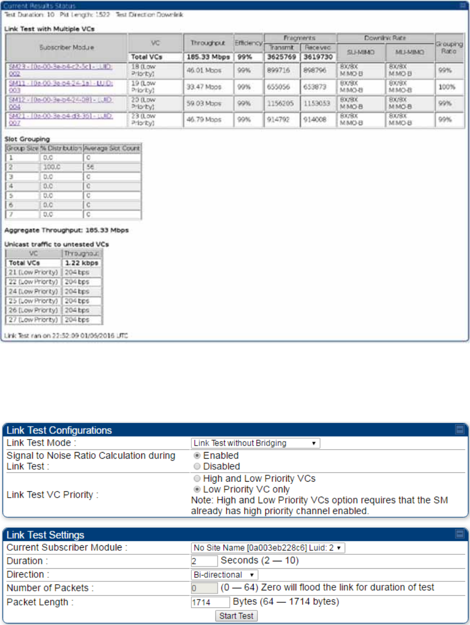
Chapter 8: Tools Using the Link Capacity Test tool
Page 8-24
Figure 171 Link Test with Multiple VCs (1518-byte packet length)
Link Test without Bridging, Link Test with Bridging or Link Test with
Bridging and MIR
Figure 172 Link Capacity Test – PMP 450/450i Series AP
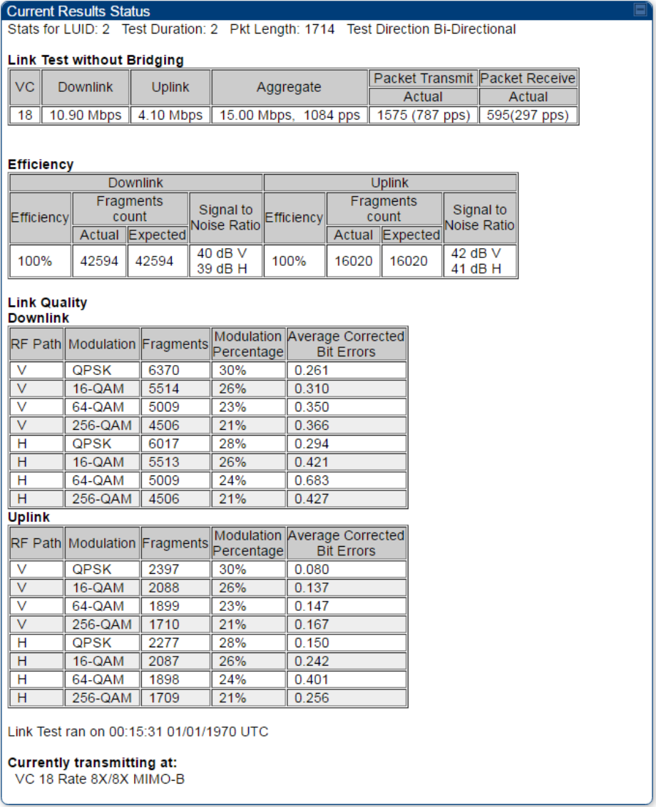
Chapter 8: Tools Using the Link Capacity Test tool
Page 8-25
Refer Link Test with Multiple VCs on page 8-22 for Link Test procedure.
Figure 173 Link Test without Bridging (1714-byte packet length)

Chapter 8: Tools Using the Link Capacity Test tool
Page 8-26
Performing Extrapolated Link Test
The Extrapolated Link Test estimates the link capacity by sending few packets and measuring link
quality. Once the test is initiated, the radio starts session at the lower modulation, 1X, as traffic is
passed successfully across the link, the radio decides to try the next modulation, 2X. This process
repeats until it find best throughput to estimate capacity of link.
Note
It is recommended to run Extrapolated Link Test where the session must have been up
and have traffic present on it in order to get accurate test results. This is essential for
the radio to modulate up to get an accurate measurement.
Running the Extrapolated test just after establishing session will not provide accurate
results.
The procedure for performing Extrapolated Link Test is as follows:
Procedure 32 Performing an Extrapolated Link Test
1 Access the Link Capacity Test tab in the Tools web page of the module.
2 Select Link Test Mode Extrapolated Link Test
3 Click the Start Test button.
4 In the Current Results Status block of this tab, view the results of the test.
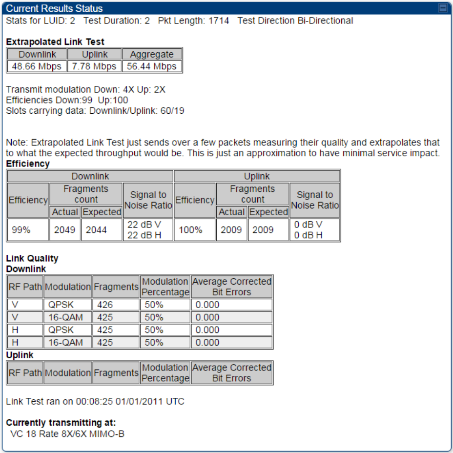
Chapter 8: Tools Using the Link Capacity Test tool
Page 8-27
Figure 174 Extrapolated Link Test results
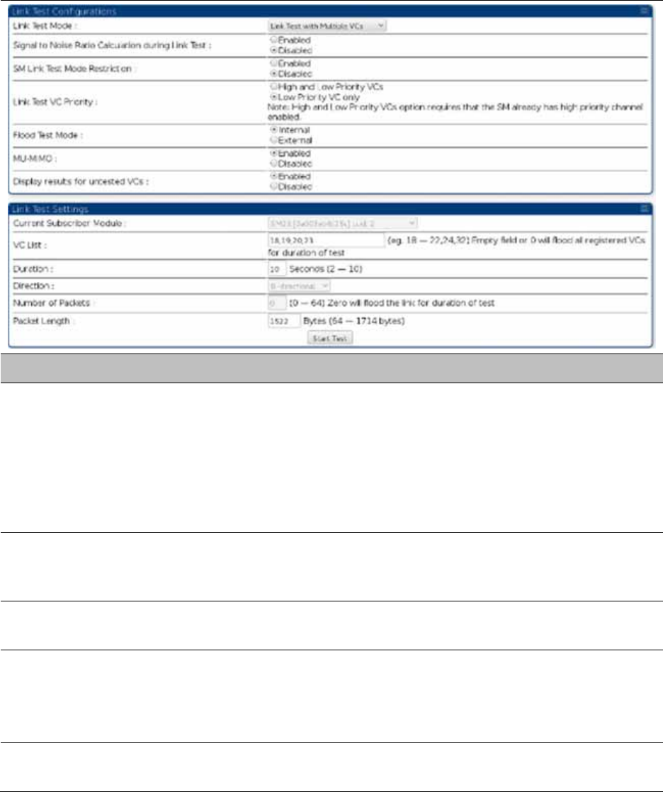
Chapter 8: Tools Using the Link Capacity Test tool
Page 8-28
Link Capacity Test page of AP
The Link Capacity Test page of AP is explained in Table 185.
Table 185 Link Capacity Test page attributes – AP
Attribute Meaning
Link Test Mode
Select Link Test Mode from drop down menu :
Link Test with Multiple VCs (PMP 450m Series AP only)
Link Test without Bridging
Link Test with Bridging
Link Test with Bridging and MIR
Extrapolated Link Test
Signal to Noise Ratio
Calculation during
Link Test
Enable this attribute to display Signal-to-Noise information for the
downlink and uplink when running the link test.
Link Test VC Priority This attribute may be used to enable/disable usage of the high and low
priority virtual channel during the link test.
Flood Test Mode
This field determines whether a packet is sent out of the SM’s Ethernet
port (external) or not (internal).
Note: This field is applicable only when the “Link Test Mode” field is set
to “Link Test with Multiple VC’s” option.
MU-MIMO This field determines whether the DL flood test packets use MU-MIMO
grouping or not.

Chapter 8: Tools Using the Link Capacity Test tool
Page 8-29
Note: This field is applicable only when the “Link Test Mode” field is set
to “Link Test with Multiple VC’s” option.
Display results for
untested VCs
If “Link test with multiple VC’s” is run and a subset of registered VC’s
enters into the VC List field, then enabling this field produces a table
that displays results for VC’s with traffic which are in session; but not
tested as part of the link test.
Current Subscriber
Module
The SM with which the Link Capacity Test is run. This field is only
applicable for AP (not SM page).
VC List
This field is displayed for PMP 450m Series AP. It is only applicable for
“Link Test with Multiple VCs” Test mode.
Enter VC List (e.g. 18 or above for low priority VCs and 255 or above for
high priority VCs or 0 for all registered VCs) which needs to be used for
link test traffic.
Duration
This field allows operators to configure a specified time for which the
spectrum is scanned. If the entire spectrum is scanned prior to the end of
the configured duration, the analyzer will restart at the beginning of the
spectrum.
Direction
Configure the direction of the link test. Specify Downlink or Uplink to run
the test only in the corresponding direction only. Specific Bi-Directional
to run the test in both directions.
Number of Packets The total number of packets to send during the Link Capacity Test. When
Link Test Mode is set to RF Link Test this field is not configurable.
Packet Length The size of the packets in Bytes to send during the Link Capacity Test
Link Capacity Test page of BHM/BHS/SM
The Link Capacity Test page of BHM/BHS is explained in Table 186.
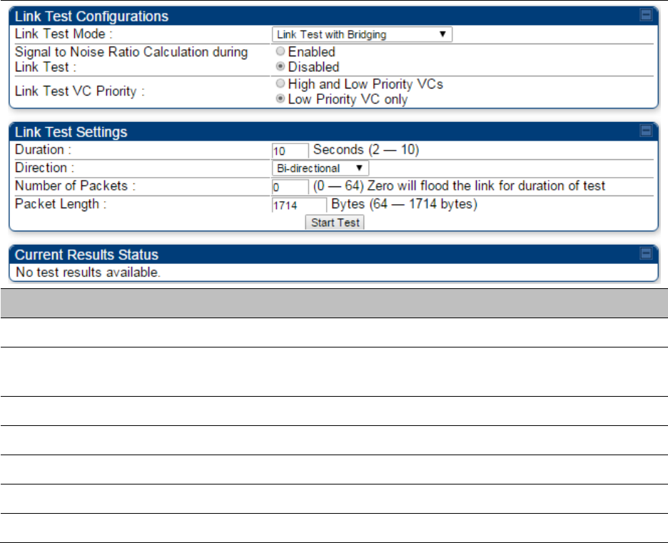
Chapter 8: Tools Using the Link Capacity Test tool
Page 8-30
Table 186 Link Capacity Test page attributes – BHM/BHS
Attribute Meaning
Link Test Mode See Table 185 on page 8-28
Signal to Noise Ratio Calculation
during Link Test See Table 185 on page 8-28
Link Test VC Priority See Table 185 on page 8-28
Duration See Table 185 on page 8-28
Direction See Table 185 on page 8-28
Number of Packets See Table 185 on page 8-28
Packet Length See Table 185 on page 8-28
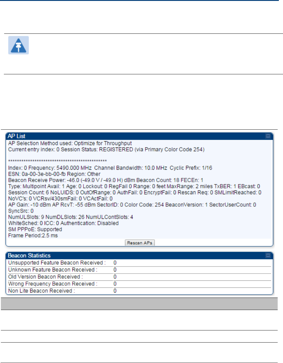
Chapter 8: Tools Using AP Evaluation tool
Page 8-31
Using AP Evaluation tool
The AP Evaluation tab on Tools web page of the SM provides information about the AP that the
SM sees.
Note
The data for this page may be suppressed by the SM Display of AP Evaluation Data
setting in the Configuration > Security tab of the AP.
The AP Eval results can be accessed via SNMP and config file.
AP Evaluation page
The AP Evaluation page of AP is explained in Table 187.
Table 187 AP Evaluation tab attributes - AP
Attribute Meaning
Index This field displays the index value that the system assigns (for only this
page) to the AP where this SM is registered.
Frequency This field displays the frequency that the AP transmits.
Channel Bandwidth The channel size used by the radio for RF transmission. The setting for
the channel bandwidth must match between the AP and the SM.

Chapter 8: Tools Using AP Evaluation tool
Page 8-32
Cyclic Prefix OFDM technology uses a cyclic prefix, where a portion of the end of a
symbol (slot) is repeated at the beginning of the symbol to allow multi-
pathing to settle before receiving the desired data. A 1/16 cyclic prefixes
mean that for every 16 bits of throughput data transmitted, an additional
bit is used. The Cyclic Prefix 1/16 only can be selected at this time.
ESN This field displays the MAC address (electronic serial number) of the AP.
For operator convenience during SM aiming, this tab retains each
detected ESN for up to 15 minutes. If the broadcast frequency of a
detected AP changes during a 15-minute interval in the aiming
operation, then a multiple instance of the same ESN is possible in the
list. Eventually, the earlier instance expires and disappears and the later
instance remains to the end of its interval, but you can ignore the early
instance(s) whenever two or more are present.
Region This field displays the AP’s configured Country Code setting.
Power Level
This field displays the SM’s combined received power level from the
AP’s transmission.
Beacon Count A count of the beacons seen in a given time period.
FECEn This field contains the SNMP value from the AP that indicates whether
the Forward Error Correction feature is enabled.
0: FEC is disabled
1: FEC is enabled
Type Multipoint indicates that the listing is for an AP.
Age This is a counter for the number of minutes that the AP has been
inactive. At 15 minutes of inactivity for the AP, this field is removed from
the AP Evaluation tab in the SM.
Lockout This field displays how many times the SM has been temporarily locked
out of making registration attempts.
RegFail This field displays how many registration attempts by this SM failed.
Range This field displays the distance in feet for this link. To derive the distance
in meters, multiply the value of this parameter by 0.3048.
MaxRange This field indicates the configured value for the AP’s Max Range
parameter.
TxBER A 1 in this field indicates the AP is sending Radio BER.
EBcast A 1 in this field indicates the AP or BHM is encrypting broadcast packets.
A 0 indicates it is not.

Chapter 8: Tools Using AP Evaluation tool
Page 8-33
Session Count
This field displays how many sessions the SM (or BHS) has had with the
AP (or BHM). Typically, this is the sum of Reg Count and Re-Reg Count.
However, the result of internal calculation may display here as a value
that slightly differs from the sum.
In the case of a multipoint link, if the number of sessions is significantly
greater than the number for other SMs, then this may indicate a link
problem or an interference problem.
NoLUIDs This field indicates how many times the AP has needed to reject a
registration request from a SM because its capacity to make LUID
assignments is full. This then locks the SM out of making any valid
attempt for the next 15 minutes. It is extremely unlikely that a non-zero
number would be displayed here.
OutOfRange This field indicates how many times the AP has rejected a registration
request from a SM because the SM is a further distance away than the
range that is currently configured in the AP. This then locks the SM out
of making any valid attempt for the next 15 minutes.
AuthFail This field displays how many times authentication attempts from this
SM have failed in the AP.
EncryptFail This field displays how many times an encryption mismatch has
occurred between the SM and the AP.
Rescan Req This field displays how many times a re-range request has occurred for
the BHM that is being evaluated in the AP Eval page of a BHS.
SMLimitReached This field displays 0 if additional SMs may be registered to the AP. If a 1
is displayed, the AP will not accept additional SM registrations.
NoVC’s This counter is incremented when the SM is registering to an AP which
determines that no VC resources are available for allocation. This could
be a primary data VC or a high priority data VC.
VCRsvFail This counter is incremented when the SM is registering to an AP which
has a VC resource available for allocation but cannot reserve the
resource for allocation.
VCActFail This counter is incremented when the SM is registering to an AP which
has a VC resource available for allocation and has reserved the VC, but
cannot activate the resource for allocation.
AP Gain This field displays the total external gain (antenna) used by the AP.
RcvT This field displays the AP’s configured receive target for receiving SM
transmissions (this field affects automatic SM power adjust).
Sector ID This field displays the value of the Sector ID field that is provisioned for
the AP.

Chapter 8: Tools Using AP Evaluation tool
Page 8-34
Color Code This field displays a value from 0 to 254 indicating the AP’s configured
color code. For registration to occur, the color code of the SM and the AP
must match. Color code is not a security feature. Instead, color code is a
management feature, typically for assigning each sector a different color
code.
Color code allows you to force a SM to register to only a specific AP,
even where the SM can communicate with multiple APs. The default
setting for the color code value is 0. This value matches only the color
code of 0 (not all 255 color codes).
BeaconVersion This field indicates that the beacon is OFDM (value of 1).
Sector User Count This field displays how many SMs are registered on the AP.
NumULHalfSlots This is the number of uplink slots in the frame for this AP.
NumDLHalfSlots This is the number of downlink slots in the frame for this.
NumULContSlots This field displays how many Contention Slots are being used in the
uplink portion of the frame.
WhiteSched Flag to display if schedule whitening is supported via FPGA
ICC This field lists the SMs that have registered to the AP with their
Installation Color Code (ICC),
Primary CC, Secondary CC or Tertiary CC.
SM PPPoE This filed provides information to the user whether the SM is supporting
PPPoE or not.
Frame Period This field displays the configured Frame Period of the radio.
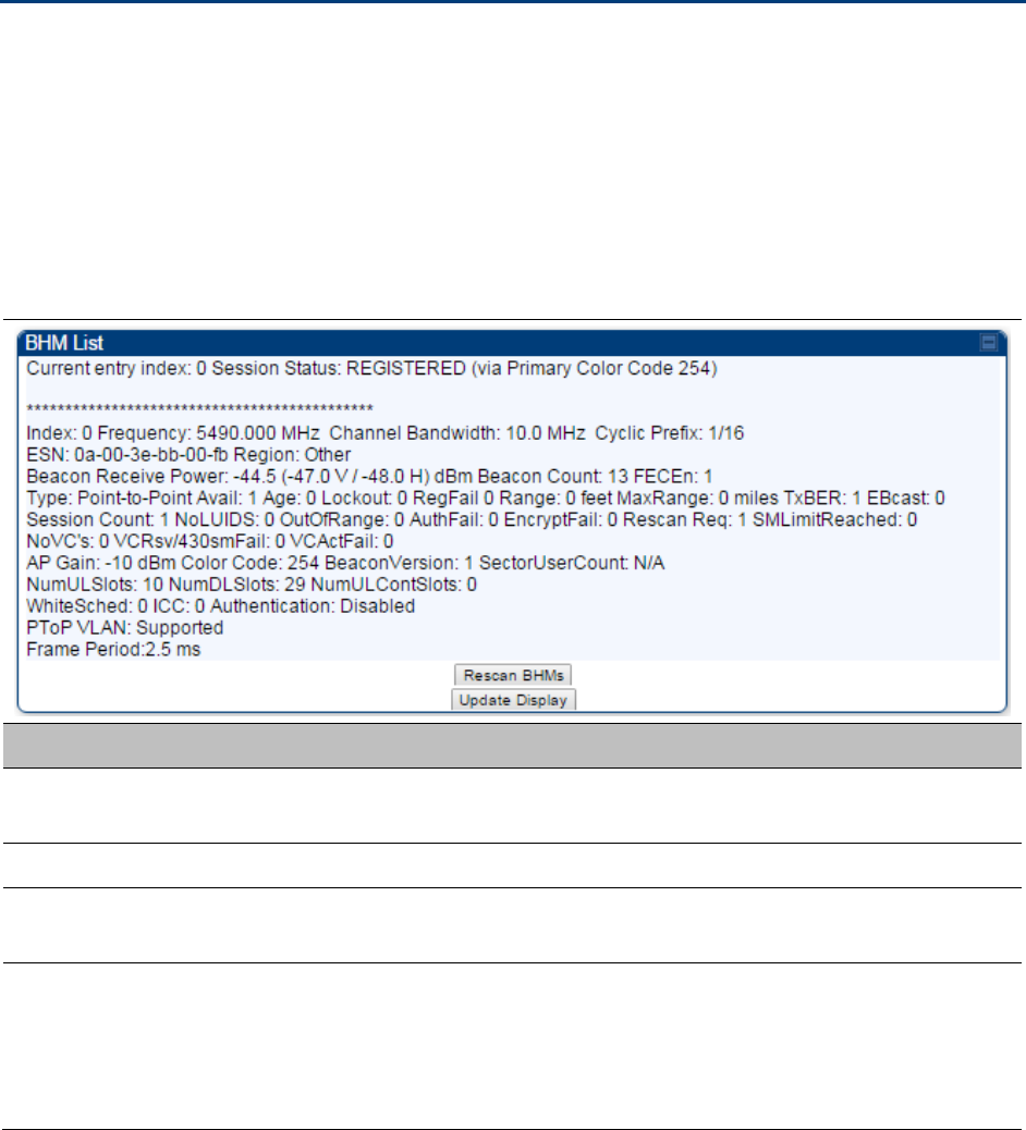
Chapter 8: Tools Using BHM Evaluation tool
Page 8-35
Using BHM Evaluation tool
The BHM Evaluation tab on Tools web page of the BHS provides information about the BHM that
the BHS sees.
BHM Evaluation page of BHS
The BHM Evaluation page of BHS is explained in Table 188.
Table 188 BHM Evaluation tab attributes - BHS
Attribute Meaning
Index This field displays the index value that the system assigns (for only this
page) to the BHM where this BHS is registered.
Frequency This field displays the frequency that the BHM transmits.
Channel Bandwidth The channel size used by the radio for RF transmission. The setting for
the channel bandwidth must match between the BHM and the BHS.
Cyclic Prefix OFDM technology uses a cyclic prefix, where a portion of the end of a
symbol (slot) is repeated at the beginning of the symbol to allow multi-
pathing to settle before receiving the desired data. A 1/16 cyclic prefixes
mean that for every 16 bits of throughput data transmitted, an additional
bit is used.

Chapter 8: Tools Using BHM Evaluation tool
Page 8-36
ESN This field displays the MAC address (electronic serial number) of the
BHM. For operator convenience during BHS aiming, this tab retains each
detected ESN for up to 15 minutes. If the broadcast frequency of a
detected BHM changes during a 15-minute interval in the aiming
operation, then a multiple instance of the same ESN is possible in the
list. Eventually, the earlier instance expires and disappears and the later
instance remains to the end of its interval, but you can ignore the early
instance(s) whenever two or more are present.
Region This field displays the BHM’s configured Country Code setting.
Power Level
This field displays the BHS’s combined received power level from the
BHM’s transmission.
Beacon Count A count of the beacons seen in a given time period.
FECEn This field contains the SNMP value from the BHM that indicates whether
the Forward Error Correction feature is enabled.
0: FEC is disabled
1: FEC is enabled
Type Multipoint indicates that the listing is for a BHM.
Age This is a counter for the number of minutes that the BHM has been
inactive. At 15 minutes of inactivity for the BHS, this field is removed
from the BHM Evaluation tab in the BHS.
Lockout This field displays how many times the BHS has been temporarily locked
out of making registration attempts.
RegFail This field displays how many registration attempts by this BHS failed.
Range This field displays the distance in feet for this link. To derive the distance
in meters, multiply the value of this parameter by 0.3048.
MaxRange This field indicates the configured value for the AP’s Max Range
parameter.
TxBER A 1 in this field indicates the BHM is sending Radio BER.
EBcast A 1 in this field indicates the BHM is encrypting broadcast packets. A 0
indicates it is not.
Session Count
This field displays how many sessions the BHS has had with the BHM.
Typically, this is the sum of Reg Count and Re-Reg Count. However, the
result of internal calculation may display here as a value that slightly
differs from the sum.
In the case of a multipoint link, if the number of sessions is significantly
greater than the number for other BHS’s, then this may indicate a link
problem or an interference problem.

Chapter 8: Tools Using BHM Evaluation tool
Page 8-37
NoLUIDs This field indicates how many times the BHM has needed to reject a
registration request from a BHS because its capacity to make LUID
assignments is full. This then locks the BHS out of making any valid
attempt for the next 15 minutes. It is extremely unlikely that a non-zero
number would be displayed here.
OutOfRange This field indicates how many times the BHM has rejected a registration
request from a BHS because the BHS is a further distance away than the
range that is currently configured in the BHM. This then locks the BHS
out of making any valid attempt for the next 15 minutes.
AuthFail This field displays how many times authentication attempts from this
SM have failed in the BHM.
EncryptFail This field displays how many times an encryption mismatch has
occurred between the BHS and the BHM.
Rescan Req This field displays how many times a re-range request has occurred for
the BHM that is being evaluated in the BHM Eval page of a BHM.
SMLimitReached This field displays 0 if additional BHSs may be registered to the BHM. If a
1 is displayed, the BHM will not accept additional BHS registrations.
NoVC’s This counter is incremented when the BHS is registering to a BHM which
determines that no VC resources are available for allocation. This could
be a primary data VC or a high priority data VC.
VCRsvFail This counter is incremented when the BHS is registering to a BHM which
has a VC resource available for allocation but cannot reserve the
resource for allocation.
VCActFail This counter is incremented when the BHS is registering to a BHM which
has a VC resource available for allocation and has reserved the VC, but
cannot activate the resource for allocation.
AP Gain This field displays the total external gain (antenna) used by the BHM.
RcvT This field displays the AP’s configured receive target for receiving BHS
transmissions (this field affects automatic BHS power adjust).
Sector ID This field displays the value of the Sector ID field that is provisioned for
the BHM.
Color Code This field displays a value from 0 to 254 indicating the BHM’s configured
color code. For registration to occur, the color code of the BHS and the
BHM must match. Color code is not a security feature. Instead, color
code is a management feature, typically for assigning each sector a
different color code.
Color code allows you to force a BHS to register to only a specific BHM,
even where the BHS can communicate with multiple BHMs. The default
setting for the color code value is 0. This value matches only the color
code of 0 (not all 255 color codes).

Chapter 8: Tools Using BHM Evaluation tool
Page 8-38
BeaconVersion This field indicates that the beacon is OFDM (value of 1).
Sector User Count This field displays how many BHS’s are registered on the BHM.
NumULHalfSlots This is the number of uplink slots in the frame for this BHM.
NumDLHalfSlots This is the number of downlink slots in the frame for this.
NumULContSlots This field displays how many Contention Slots are being used in the
uplink portion of the frame.
WhiteSched Flag to display if schedule whitening is supported via FPGA
ICC This field lists the BHSs that have registered to the BHM with their
Installation Color Code (ICC),
Primary CC, Secondary CC or Tertiary CC.
SM PPPoE This filed provides information to the user whether the BHS is
supporting PPPoE or not.
Frame Period This field displays the configured Frame Period of the radio.

Chapter 8: Tools Using the OFDM Frame Calculator tool
Page 8-39
Using the OFDM Frame Calculator tool
The first step to avoid interference in wireless systems is to set all APs/BHMs to receive timing
from a synchronization source (Cluster Management Module, or Universal Global Positioning
System). This ensures that the modules are in sync and start transmitting at the same time each
frame.
The second step to avoid interference is to configure parameters on all APs/BHMs of the same
frequency band in proximity such that they have compatible transmit/receive ratios (all stop
transmitting each frame before any start receiving). This avoids the problem of one AP/BHM
attempting to receive the signal from a distant SM/BHS while a nearby AP transmits, which could
overpower that signal.
The following parameters on the AP determine the transmit/receive ratio:
Max Range
Frame Period
Downlink Data percentage
(reserved) Contention Slots
If OFDM (PMP 430, PMP 450, PTP 230) and FSK (PMP 1x0) APs/BHMs of the same frequency band
are in proximity, or if APs/BHMs set to different parameters (differing in their Max Range values,
for example), then operator must use the Frame Calculator to identify compatible settings.
The frame calculator is available on the Frame Calculator tab of the Tools web page. To use the
Frame Calculator, type various configurable parameter values into the calculator for each proximal
AP and then record the resulting AP/BHM Receive Start value. Next vary the Downlink Data
percentage in each calculation and iterate until the calculated AP/BHM Receive Start for all
collocated AP/BHMs where the transmit end does not come before the receive start.
The calculator does not use values in the module or populate its parameters. It is merely a
convenience application that runs on a module. For this reason, you can use any FSK module (AP,
SM, BHM, BHS) to perform FSK frame calculations for setting the parameters on an FSK AP and
any OFDM module (AP, SM, BHM, BHS) to perform OFDM frame calculations for setting the
parameters on an OFDM AP/BHM.
For more information on PMP/PTP 450 Platform co-location, see
http://www.cambiumnetworks.com/solution-papers
The co-location is also supported for 900 MHz PMP 450i APs (OFDM) and PMP 100 APs (FSK).
Please refer Co-location of PMP 450 and PMP 100 systems in the 900 MHz band and migration
recommendations document for details.
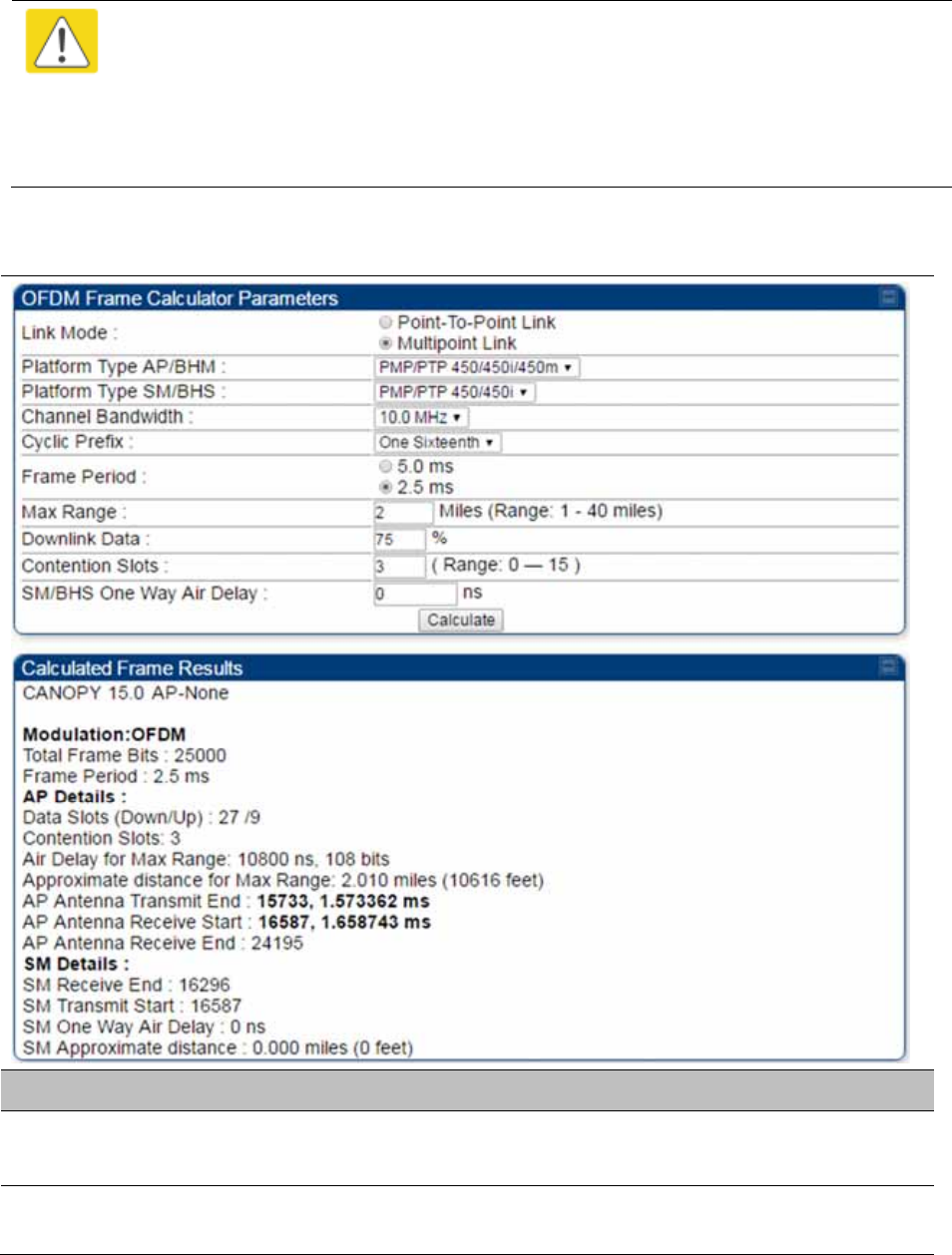
Chapter 8: Tools Using the OFDM Frame Calculator tool
Page 8-40
Caution
APs/BHMs that have slightly mismatched transmit-to-receive ratios and low levels of
data traffic may see little effect on throughput. A system that was not tuned for co-
location may work fine at low traffic levels, but encounter problems at higher traffic
levels. The conservative practice is to tune for co-location before traffic ultimately
increases. This prevents problems that occur as sectors are built.
The OFDM Frame Calculator page is explained in Table 189.
Table 189 OFDM Frame Calculator page attributes
Attribute Meaning
Link Mode For AP to SM frame calculations, select Multipoint Link
For BHM to BHS frame calculations, select Point-To-Point Link
Platform Type
AP/BHM
Use the drop-down list to select the hardware series (board type) of the
AP/BHM.

Chapter 8: Tools Using the OFDM Frame Calculator tool
Page 8-41
Platform Type
SM/BHS
Use the drop-down list to select the hardware series (board type) of the
SM/BHS.
Channel Bandwidth Set this to the channel bandwidth used in the AP/BHM.
Cyclic Prefix Set this to the cyclic prefix used in the AP/BHM.
Max Range Set to the same value as the Max Range parameter is set in the AP(s) or
BHM(s).
Frame Period Set to the same value as the Frame Period parameter is set in the AP(s)
or BHM(s).
Downlink Data Initially set this parameter to the same value that the AP/BHM has for its
Downlink Data parameter (percentage). Then, use the Frame Calculator
tool procedure as described in Using the Frame Calculator on page 8-42,
you will vary the value in this parameter to find the proper value to write
into the Downlink Data parameter of all APs or BHMs in the cluster.
PMP 450 Platform Family APs or BHMs offer a range of 15% to 85% and
default to 75%. The value that you set in this parameter has the
following interaction with the value of the Max Range parameter
(above):
The default Max Range value is 5 miles and, at that distance, the
maximum Downlink Data value (85% in PMP 450 Platform) is functional.
Contention Slots This field indicates the number of (reserved) Contention Slots configured
by the operator. Set this parameter to the value of the Contention Slot
parameter is set in the APs or BHMs.
SM/BHS One Way
Air Delay
This field displays the time in ns (nano seconds), that a SM/BHS is away
from the AP/BHM.
The Calculated Frame Results display several items of interest:
Table 190 OFDM Calculated Frame Results attributes
Attribute Meaning
Modulation The type of radio modulation used in the calculation (OFDM for 450
Platform Family)
Total Frame Bits The total number of bits used in the calculated frames
Data Slots
(Down/Up)
This field is based on the Downlink Data setting. For example, a result
within the typical range for a Downlink Data setting of 75% is 61/21,
meaning 61 data slots down and 21 data slots up.
Contention Slots This field indicates the number of (reserved) Contention Slots configured
by the operator.
Air Delay for Max
Range
This is the roundtrip air delay in bit times for the Max Range value set in
the calculator

Chapter 8: Tools Using the OFDM Frame Calculator tool
Page 8-42
Approximate
distance for Max
Range
The Max Range value used for frame calculation
AP Transmit End In bit times, this is the frame position at which the AP/BHM ceases
transmission.
AP Receive Start In bit times, this is the frame position at which the AP/BHM is ready to
receive transmission from the SM/BHS.
AP Receive End In bit times, this is the frame position at which the AP/BHM will cease
receiving transmission from the SM/BHS.
SM Receive End In bit times, this is the frame position at which the SM/BHS will cease
receiving transmission from the AP/BHM.
SM Transmit Start In bit times, this is the frame position at which the SM/BHS starts the
transmission.
SM One Way Air
Delay
This filed displays the time in ns, that SM/BHS is away from the AP/BHM.
SM Approximate
distance
This field displays an approximate distance in miles (feet) that the
SM/BHS is away from the AP/BHM.
To use the Frame Calculator to ensure that all APs or BHMs are configured to transmit and receive
at the same time, follow the procedure below:
Procedure 33 Using the Frame Calculator
1 Populate the OFDM Frame Calculator parameters with appropriate values as
described above.
2 Click the Calculate button.
3 Scroll down the tab to the Calculated Frame Results section
4 Record the value of the AP Receive Start field
5 Enter a parameter set from another AP in the system – for example, an AP in the same
cluster that has a higher Max Range value configured.
6 Click the Calculate button.
7 Scroll down the tab to the Calculated Frame Results section
8 If the recorded values of the AP Receive Start fields are within 150 bit times of each
other, skip to step 10.
If the recorded values of the AP Receive Start fields are not within 150 bit times of
each other, modify the Downlink Data parameter until the calculated results for AP
Receive Start are within 300 bit time of each other, if possible, 150 bit time.
Chapter 8: Tools Using the OFDM Frame Calculator tool
Page 8-43
10 Access the Radio tab in the Configuration web page of each AP in the cluster and
change its Downlink Data parameter (percentage) to the last value that was used in
the Frame Calculator.
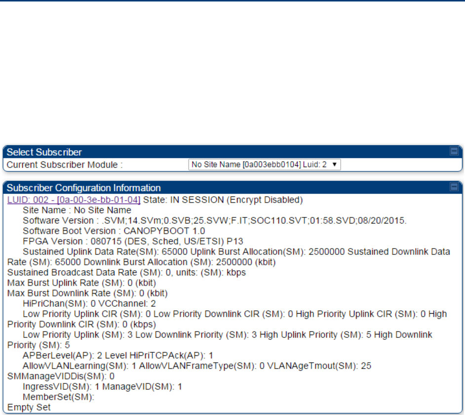
Chapter 8: Tools Using the Subscriber Configuration tool
Page 8-44
Using the Subscriber Configuration tool
The Subscriber Configuration page in the Tools page of the AP displays:
The current values whose control may be subject to the setting in the Configuration Source
parameter.
An indicator of the source for each value.
This page may be referenced for information on how the link is behaving based on where the SM
is retrieving certain QoS and VLAN parameters.
Figure 175 SM Configuration page of AP
The AP displays one of the following for the configuration source:
(SM) – QoS/VLAN parameters are derived from the SM’s settings
(APCAP) – QoS/VLAN parameters are derived from the AP’s settings, including any keyed
capping (for radios capped at 4 Mbps, 10 Mbps, or 20 Mbps)
(D) – QoS/VLAN parameters are retrieved from the device, due to failed retrieval from the AAA
or WM server.
(AAA) – QoS/VLAN parameters are retrieved from the RADIUS server
(BAM) – QoS/VLAN parameters are retrieved from a WM BAM server

Chapter 8: Tools Using the Link Status tool
Page 8-45
Using the Link Status tool
The Link Status Tool displays information about the most-recent Link Test initiated on the SM or
BHS. Link Tests initiated from the AP or BHM are not included in the Link Status table. This table is
useful for monitoring link test results for all SMs or BHS in the system.
The Link Status table is color coded to display health of link between AP/BHM and SM/BHS. The
current Modulation Level Uplink/Downlink is chosen to determine link health and color coded
accordingly.
Uplink/Downlink Rate Column will be color coded using current Rate as per the table below:
Table 191 Color code versus uplink/downlink rate column
Actual Rate 1x 2x
3x
4x
6x
8x
SISO RED ORANGE
GREEN
BLUE
NA NA
MIMO-A RED ORANGE
GREEN
BLUE
NA NA
MIMO B NA RED
NA
ORANGE
GREEN BLUE
Link Status – AP/BHM
The current Uplink Rate (both low and high VC) for each SM or BHS in Session in now available on
AP or BHM Link Status Page.
The Link Status tool results include values for the following fields for AP/BHM.
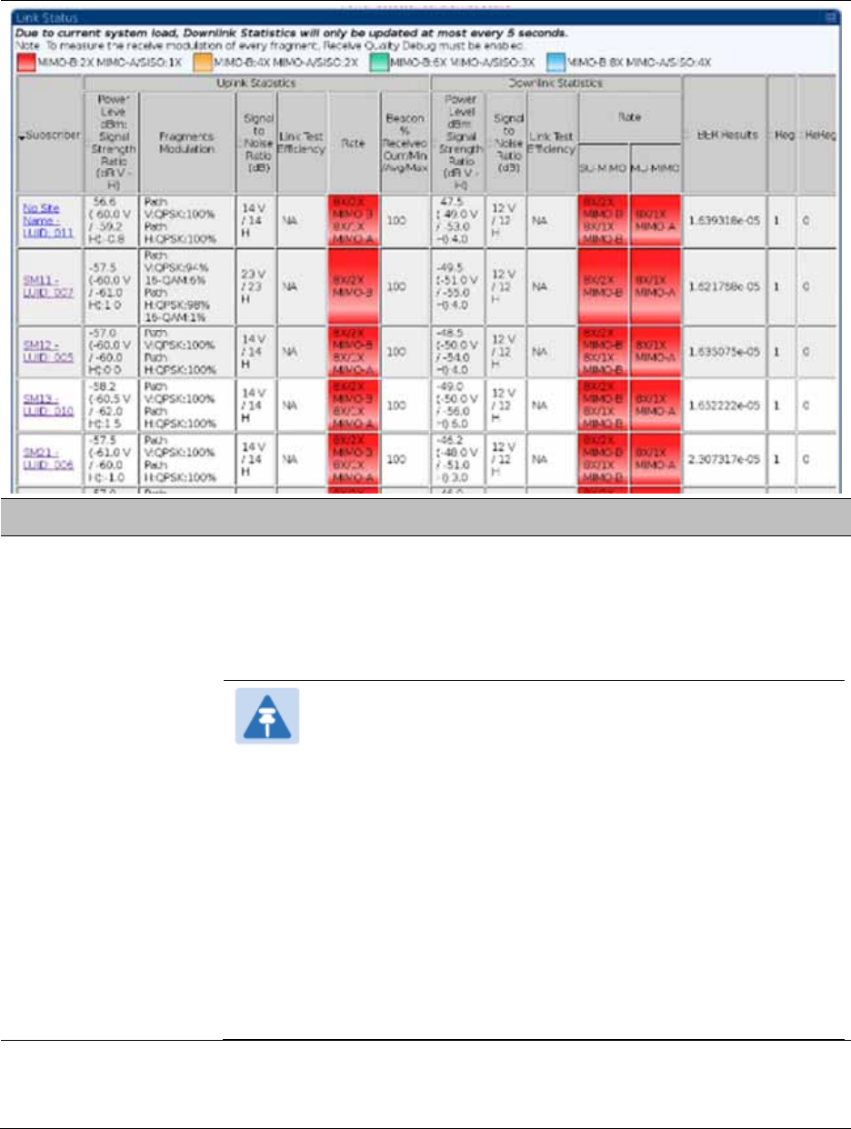
Chapter 8: Tools Using the Link Status tool
Page 8-46
Table 192 Link Status page attributes – AP/BHM
Attribute Meaning
Subscriber This field displays the LUID (logical unit ID), MAC address and Site Name
of the SM. As each SM registers to the AP, the system assigns an LUID
of 2 or a higher unique number to the SM. If a SM loses registration with
the AP and then regains registration, the SM will retain the same LUID.
Note
The LUID associated is lost when a power cycle of the AP
occurs.
Both the LUID and the MAC are hot links to open the
interface to the SM. In some instances, depending on
network activity and network design, this route to the
interface yields a blank web page. If this occurs, refresh
your browser view.
Site Name indicates the name of the SM. You can assign or
change this name on the Configuration web page of the
SM. This information is also set into the sysName SNMP
MIB-II object and can be polled by an SNMP management
server.
Uplink Statistics -
Power Level: Signal
Strength Ratio
This field represents the combined received power level at the AP/BHM
as well as the ratio of horizontal path signal strength to vertical path
signal strength.

Chapter 8: Tools Using the Link Status tool
Page 8-47
Uplink Statistics –
Fragments
Modulation
This field represents the percentage of fragments received at each
modulation state, per path (polarization).
Uplink Statistics –
Signal to Noise Ratio
This field represents the signal to noise ratio for the uplink (displayed
when parameter Signal to Noise Ratio Calculation during Link Test is
enabled) expressed for both the horizontal and vertical channels.
Uplink Statistics –
Link Test Efficiency
This field displays the efficiency of the radio link, expressed as a
percentage, for the radio uplink.
Downlink Statistics –
Beacon % Received
Curr/Min/Max/Avg
This field displays a count of beacons received by the SM in percentage.
This value must be between 99-100%. If it is lower than 99%, it indicates
a problematic link. This statistic is updated every 16 seconds.
Downlink Statistics –
Power Level: Signal
Strength Ratio
This field represents the received power level at the SM/BHS as well as
the ratio of horizontal path signal strength to vertical path signal
strength at the SM/BHS.
Downlink Statistics –
Signal to Noise Ratio
This field represents the signal to noise ratio for the downlink (displayed
when parameter Signal to Noise Ratio Calculation during Link Test is
enabled) expressed for both the horizontal and vertical channels.
Downlink Statistics –
Link Test Efficiency
This field displays the efficiency of the radio link, expressed as a
percentage, for the radio downlink.
Downlink Statistics –
SU-MIMO Rate
The SU-MIMO rate applies to all AP platforms.
For 450m, this field indicates the rate being used for symbols where this
particular VC is not being MU-MIMO grouped with other SM’s.
For 450 and 450i platforms, there is no grouping and this field indicates
the modulation rate for all symbols.
Downlink Statistics –
MU-MIMO Rate
The MU-MIMO rate applies only to the 450m AP. This field indicates the
modulation rate used for symbols where this particular low priority VC is
MU-MIMO scheduled by grouping it in the same slot with other low
priority VC’s.
BER Results This field displays the over-the-air Bit Error Rates for each downlink.
(The ARQ [Automatic Resend reQuest] ensures that the transport BER
[the BER seen end-to-end through a network] is essentially zero.) The
level of acceptable over-the-air BER varies, based on operating
requirements, but a reasonable value for a good link is a BER of 1e-4 (1 x
10-4) or better, approximately a packet resend rate of 5%.
BER is generated using unused bits in the downlink. During periods of
peak load, BER data is not updated as often, because the system puts
priority on transport rather than on BER calculation.
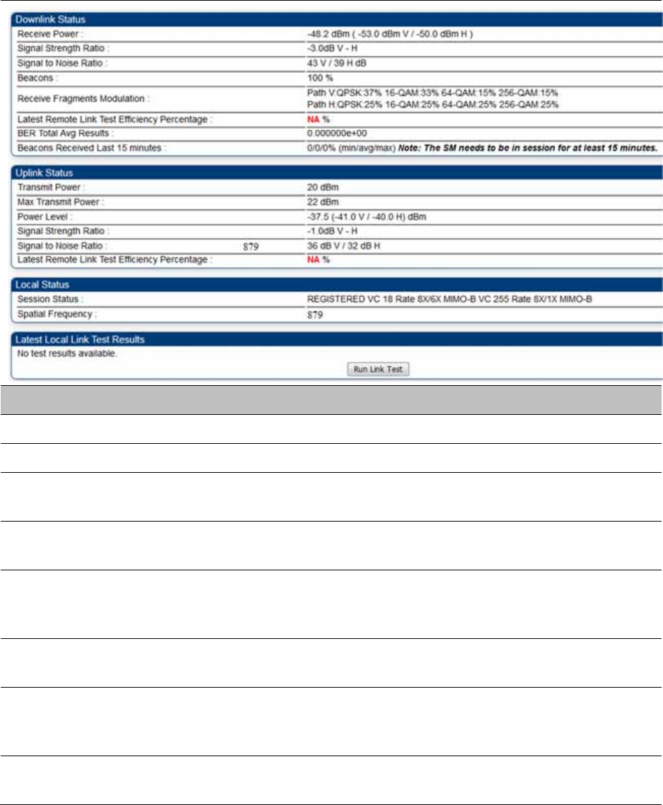
Chapter 8: Tools Using the Link Status tool
Page 8-48
Link Status – SM/BHS
The Link Status tool of SM/BHS displays Downlink Status and Uplink Status information.
Table 193 Link Status page attributes – SM/BHS
Attribute Meaning
Downlink Status
Receive Power This field lists the current combined receive power level, in dBm.
Signal Strength
Ratio
This field displays the difference of the Vertical path received signal
power to the Horizontal path received signal power for downlink.
Signal to Noise Ratio This field lists the current signal-to-noise level, an indication of the
separation of the received power level vs. noise floor for downlink.
Beacons Displays a count of beacons received by the SM in percentage. This
value must be typically between 99-100%. If lower than 99%, it indicates
a problematic link. This statistic is updated every 16 seconds.
Received Fragments
Modulation
This field represents the percentage of fragments received at each
modulation state, per path (polarization)
Latest Remote Link
Test Efficiency
Percentage
This field is not applicable.
BER Total Avg
Results
This field displays the over-the-air average Bit Error Rates (BER) for
downlink.
Chapter 8: Tools Using the Link Status tool
Page 8-49
Beacons Received
Last 15 minutes
The beacon count on the SM can be used to estimate the interference in
the channel. The min/avg/max beacon percentage displayed based on
this value for the last 15 mins.
Uplink Status
Transmit Power This field displays the current combined transmit power level, in dBm.
Max Transmit Power This field displays the maximum transmit power of SM.
Power Level This field indicates the combined power level at which the SM is set to
transmit, based on the Country Code and Antenna Gain settings.
Signal Strength
Ratio
This field displays the difference of the Vertical path received signal
power to the Horizontal path received signal power for uplink.
Signal to Noise Ratio This field lists the current signal-to-noise level, an indication of the
separation of the received power level vs. noise floor for uplink.
Latest Remote Link
Test Efficiency
Percentage
This field is not applicable.
Session Status This field displays the current state, Virtual channel, high-priority/ low
priority channel rate adaptation and MIMO-A/MIMO-B/SISO status of
SM.
Spatial Frequency This filed displays the spatial frequency value of the VC or SM.
Run Link Test
See Exploratory Test section of Performing Extrapolated Link Test on
page 8-26
Chapter 8: Tools Using BER Results tool
Page 8-50
Using BER Results tool
Radio BER data represents bit errors at the RF link level. Due to CRC checks on fragments and
packets and ARQ (Automatic Repeat reQuest), the BER of customer data is essentially zero. Radio
BER gives one indication of link quality. Other important indications to consider includes the
received power level, signal to noise ratio and link tests.
BER is only instrumented on the downlink and is displayed on the BER Results tab of the Tools
page in any SM. Each time the tab is clicked, the current results are read and counters are reset to
zero.
The BER Results tab can be helpful in troubleshooting poor link performance.
The link is acceptable if the value of this field is less than 10−4. If the BER is greater than 10−4, re-
evaluate the installation of both modules in the link.
The BER test signal is broadcast by the AP/BHM (and compared to the expected test signal by the
SM/BHS) only when capacity in the sector allows it. This signal is the lowest priority for AP/BHM
transmissions.
Figure 176 BER Results tab of the SM
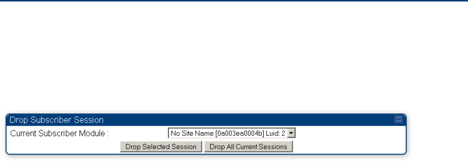
Chapter 8: Tools Using the Sessions tool
Page 8-51
Using the Sessions tool
The PMP 450 Platform Family AP has a tab Sessions under the Tools category which allows
operators to drop one or all selected SM sessions and force a SM re-registration. This operation is
useful to force QoS changes for SMs without losing AP logs or statistics. This operation may take 5
minutes to regain all SM registrations.
Figure 177 Sessions tab of the AP

Page 9-1
Chapter 9: Operation
This chapter provides instructions for operators of the 450 Platform Family wireless Ethernet
Bridge. The following topics are described in this chapter:
System information on page 9-2
o Viewing General Status on page 9-2
o Viewing Session Status on page 9-20
o Viewing Remote Subscribers on page 9-27
o Interpreting messages in the Event Log on page 9-27
o Viewing the Network Interface on page 9-30
o Viewing the Layer 2 Neighbors on page 9-31
System statistics on page 9-32
o Viewing the Scheduler statistics on page 9-32
o Viewing list of Registration Failures statistics on page 9-34
o Interpreting Bridging Table statistics on page 9-35
o Interpreting Translation Table statistics on page 9-36
o Interpreting Ethernet statistics on page 9-37
o Interpreting RF Control Block statistics on page 9-40
o Interpreting VLAN statistics on page 9-43
o Interpreting Data VC statistics on page 9-45
o Interpreting Throughput statistics on page 9-47
o Interpreting Overload statistics on page 9-50
o Interpreting DHCP Relay statistics on page 9-52
o Interpreting Filter statistics on page 9-54
o Viewing ARP statistics on page 9-55
o Viewing NAT statistics on page 9-55
o Viewing NAT DHCP Statistics on page 9-57
o Interpreting Sync Status statistics on page 9-58
o Interpreting PPPoE Statistics for Customer Activities on page 9-59
o Interpreting Bridge Control Block statistics on page 9-61
o Interpreting Pass Through Statistics on page 9-64
o Interpreting SNMPv3 Statistics on page 9-65
o Interpreting syslog statistics on page 9-67
o Interpreting Frame Utilization statistics on page 9-67
Radio Recovery on page 9-72

Chapter 9: Operation System information
Page 9-2
System information
This section describes how to use the summary and status pages to monitor the status of the
Ethernet ports and wireless link.
Viewing General Status on page 9-2
Viewing Session Status on page 9-20
Viewing Remote Subscribers on page 9-27
Interpreting messages in the Event Log on page 9-27
Viewing the Network Interface on page 9-30
Viewing the Layer 2 Neighbors on page 9-31
Viewing General Status
The General Status tab provides information on the operation of this AP/BHM and SM/BHS. This is
the page that opens by default when you access the GUI of the radio.
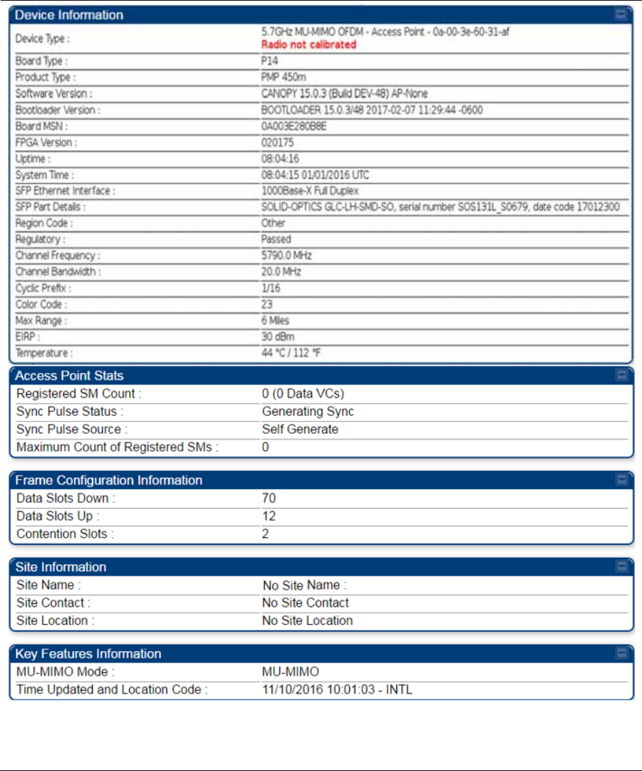
Chapter 9: Operation System information
Page 9-3
General Status page of AP
The General Status page of PMP 450m AP is explained in Table 194
The General Status page of PMP 450/450i AP is explained in Table 195.
Table 194 General Status page attributes – PMP 450m AP

Chapter 9: Operation System information
Page 9-4
Attribute Meaning
Device Type This field indicates the type of the module. Values include the frequency
band of the device, its module type and its MAC address.
Board Type This field indicates the series of hardware.
Software Version This field indicates the system release, the time and date of the release
and whether communications involving the module are secured by DES
or AES encryption. If you request technical support, provide the
information from this field.
Bootloader Version This field indicates the version of Uboot running on the 450m AP
platform.
Product Type The field indicates model number of 450m device. The 450m Series has
two model variants.
PMP 450m: This model works in SU-MIMO mode which is default
“limited” mode. The MU-MIMO license can be purchased from
Cambium Networks and applied.
MU-MIMO: This model works in MU-MIMO mode.
Board MSN This field indicates the Manufacture’s Serial number. A unique serial
number assigned to each radio at the factory for inventory and quality
control.
FPGA Version This field indicates the version of the field-programmable gate array
(FPGA) on the module. If you request technical support, provide the
value of this field.
Uptime This field indicates how long the module has operated since power was
applied.
System Time This field provides the current time. If the AP is connected to a CMM4,
then this field provides GMT (Greenwich Mean Time). Any SM that
registers to the AP inherits the system time.
Last NTP Time
Update
This field displays when the AP last used time sent from an NTP server.
If the AP has not been configured in the Time tab of the Configuration
page to request time from an NTP server, then this field is populated by
00:00:00 00/00/00.
Main Ethernet
Interface
This field indicates the speed and duplex state of the Ethernet interface
to the AP.
Aux Ethernet
Interface
This field displays Aux Ethernet Data and PoE-out interface
enable/disable status. It is not supported in current release of PMP 450m
Seriea AP.

Chapter 9: Operation System information
Page 9-5
Region Code A parameter that offers multiple fixed selections, each of which
automatically implements frequency band range for the selected region.
Units shipped to regions other than restrictions the United States must
be configured with the corresponding Region Code to comply with local
regulatory requirements.
Regulatory
This field indicates whether the configured Country Code and radio
frequency are compliant with respect to their compatibility. 450 Platform
Family products shipped to the United States is locked to a Country
Code setting of “United States”. Units shipped to regions other than the
United States must be configured with the corresponding Country Code
to comply with local regulatory requirements.
Channel Frequency This field indicates the current operating center frequency, in MHz.
Channel Bandwidth This field indicates the current size of the channel band used for radio
transmission.
Cyclic Prefix OFDM technology uses a cyclic prefix, where a portion of the end of a
symbol (slot) is repeated at the beginning of the symbol to allow multi-
pathing to settle before receiving the desired data. A 1/16 cyclic prefix
means that for every 16 bits of throughput data transmitted, an
additional bit is used.
Frame Period This field indicates the current Frame Period setting of the radio in ms.
Color Code This field displays a value from 0 to 254 indicating the AP’s configured
color code. For registration to occur, the color code of the SM and the AP
must match. Color code is not a security feature. Instead, color code is a
management feature, typically for assigning each sector a different color
code.
Color code allows you to force a SM to register to only a specific AP,
even where the SM can communicate with multiple APs. The default
setting for the color code value is 0. This value matches only the color
code of 0 (not all 255 color codes).
Max Range This field indicates the setting of the Max Range parameter, which
contributes to the way the radio transmits. Verify that the Max Range
parameter is set to a distance slightly greater than the distance between
the AP and the furthest SM that must register to this AP.
EIRP This field indicates the combined power level at which the AP will
transmit, based on the Country Code.
Temperature This field indicates the current operating temperature of the device
board.
Registered SM Count This field indicates how many SMs are registered to the AP.
Sync Pulse Status
This field indicates the status of synchronization as follows:

Chapter 9: Operation System information
Page 9-6
Generating Sync indicates that the module is set to generate the sync
pulse.
Receiving Sync indicates that the module is set to receive a sync pulse
from an outside source and is receiving the pulse.
No Sync Since Boot up / ERROR: No Sync Pulse indicates that the
module is set to receive a sync pulse from an outside source and is not
receiving the pulse.
Note
When this message is displayed, the AP transmitter is
turned off to avoid self-interference within the system.
Sync Pulse Source This field indicates the status of the synchronization source:
Searching indicates that the unit is searching for a GPS fix
Timing Port/UGPS indicates that the module is receiving sync via the
timing AUX/SYNC timing port
Power Port indicates that the module is receiving sync via the power
port (Ethernet port).
On-board GPS indicates that the module is receiving sync via the unit’s
internal GPS module
Maximum Count of
Registered SMs
This field displays the largest number of SMs that have been
simultaneously registered in the AP since it was last rebooted. This
count can provide some insight into sector history and provide
comparison between current and maximum SM counts at a glance.
Data Slots Down This field indicates the number of frame slots that are designated for use
by data traffic in the downlink (sent from the AP to the SM). The AP
calculates the number of data slots based on the Max Range, Downlink
Data and (reserved) Contention Slots configured by the operator.
Data Slots Up
This field indicates the number of frame slots that are designated for use
by data traffic in the uplink (sent from the SM to the AP). The AP
calculates the number of data slots based on the Max Range, Downlink
Data and (reserved) Contention Slots configured by the operator.
Contention Slots This field indicates the number of (reserved) Contention Slots configured
by the operator. See Contention slots on page7-166.
Connection Status This field indicates the device connectivity to cnMaestro (Cambium’s
cloud-based network management system).
Account ID This field shows Account ID which is registered with Cambium Networks
and it allows operator to manage devices using cnMaestro.
Site Name This field indicates the name of the physical module. You can assign or
change this name in the SNMP tab of the AP Configuration page. This
information is also set into the sysName SNMP MIB-II object and can be
polled by an SNMP management server.

Chapter 9: Operation System information
Page 9-7
Site Contact This field indicates contact information for the physical module. You can
provide or change this information in the SNMP tab of the AP
Configuration page. This information is also set into the sysName SNMP
MIB-II object and can be polled by an SNMP management server.
Site Location This field indicates site information for the physical module. You can
provide or change this information in the SNMP tab of the AP
Configuration page.
MU-MIMO Mode This field displays information about MU-MIMO mode. If AP is keyed as
MU-MIMO, it will display “MU-MIMO”(Multi User - MIMO) otherwise it
will display “SU-MIMO”(Single User - MIMO).
Time Updated and
Location Code
This field displays information about the keying of the radio.
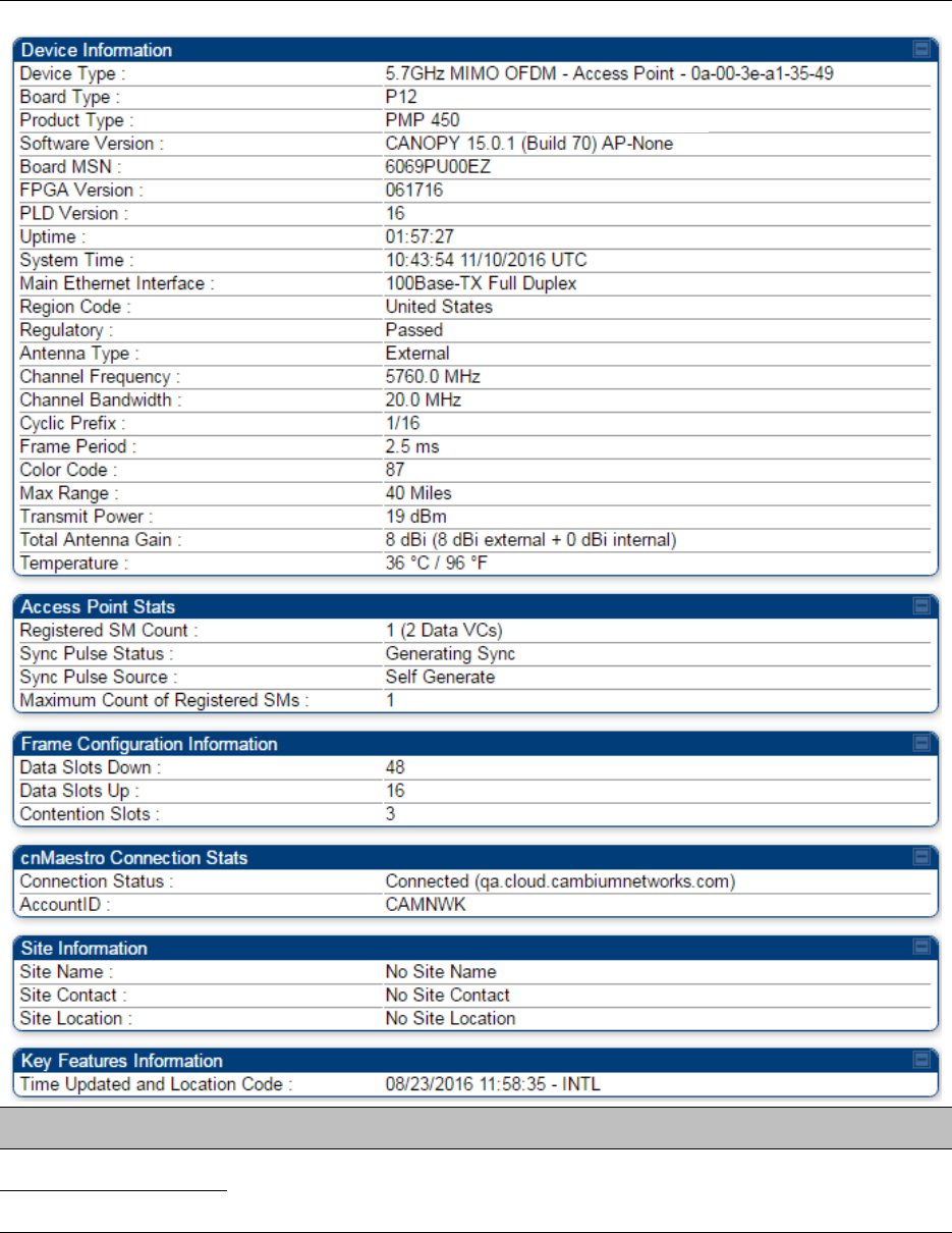
Chapter 9: Operation System information
Page 9-8
Table 195 General Status page attributes – PMP 450/450i AP
Attribute Meaning
Device Type See Table 194 General Status page attributes – PMP 450m AP on page 9-
3 for details
Software Version

Chapter 9: Operation System information
Page 9-9
Board Type See Table 194 General Status page attributes – PMP 450m AP on page 9-
3 for details
Product Type This indicates model of the device.
FPGA Version See Table 194 General Status page attributes – PMP 450m AP on page 9-
3 for details
PLD Version
Uptime
System Time
Main Ethernet
Interface
Aux Ethernet
Interface
It is not supported for PMP 450 Series devices. See Table 194 General
Status page attributes – PMP 450m AP on page 9-3 for details
Region Code See Table 194 General Status page attributes – PMP 450m AP on page 9-
3 for details
Regulatory
Antenna Type
Channel Center
Frequency
Channel Bandwidth
Cyclic Prefix
Frame Period
Color Code
Max Range
Transmitter Output
Power
This field indicates the combined power level at which the AP is set to
transmit, based on the Country Code and Antenna Gain settings.
Temperature See Table 194 General Status page attributes – PMP 450m AP on page 9-
3 for details
802.3at Type 2 PoE
Status
The field displays whether PoE Classification functionality is enabled or
disabled. It is only applicable for 450i Series devices.
Registered SM Count See Table 194 General Status page attributes – PMP 450m AP on page 9-
3 for details
Sync Pulse Status
Sync Pulse Source
Maximum Count of
Registered SMs
Data Slots Down

Chapter 9: Operation System information
Page 9-10
Data Slots Up
Contention Slots
Connection Status
Account ID See Table 194 General Status page attributes – PMP 450m AP on page 9-
3 for details
Site Name
Site Contact
Site Location
Time Updated and
Location Code
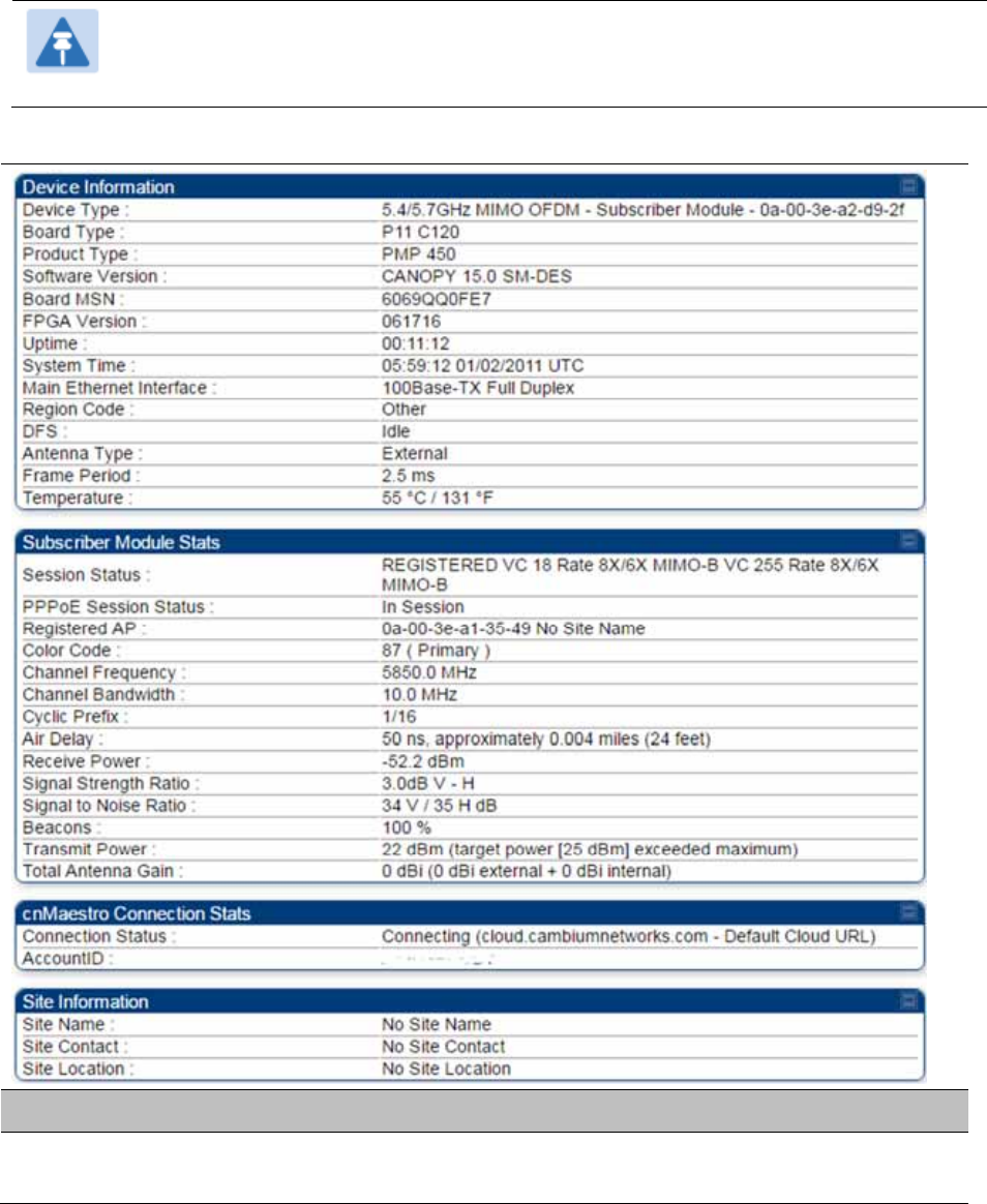
Chapter 9: Operation System information
Page 9-11
General Status page - SM
The SM’s General Status page is explained in Table 196.
Note
In order for accurate power level readings to be displayed, traffic must be present on
the radio link.
Table 196 General Status page attributes - SM
Attribute Meaning
Device Type This field indicates the type of the module. Values include the frequency
band of the SM, its module type and its MAC address.

Chapter 9: Operation System information
Page 9-12
Board Type This field indicates the series of hardware.
Product Type This indicates model of the device.
Software Version This field indicates the system release, the time and date of the release.
If you request technical support, provide the information from this field.
FPGA Version This field indicates the version of the field-programmable gate array
(FPGA) on the module. When you request technical support, provide the
information from this field.
PLD Version This field indicates the version of the programmable logic device (PLD)
on the module. If you request technical support, provide the value of this
field.
Uptime This field indicates how long the module has operated since power was
applied.
System Time This field provides the current time. Any SM that registers to an AP
inherits the system time, which is displayed in this field as GMT
(Greenwich Mean Time).
Ethernet Interface This field indicates the speed and duplex state of Ethernet interface to
the SM.
Regional Code
A parameter that offers multiple fixed selections, each of which
automatically implements frequency band range restrictions for the
selected region. Units shipped to regions other than the United States
must be configured with the corresponding Country Code to comply
with local regulatory requirements.
DFS This field indicates that DFS operation is enabled based on the
configured region code, if applicable.
Antenna Type The current antenna type that has been selected.
Frame Period This field indicates the current Frame Period setting of the radio in ms.
Temperature The current operating temperature of the board.
Session Status
This field displays the following information about the current session:
Scanning indicates that this SM currently cycles through the radio
frequencies that are selected in the Radio tab of the Configuration page.
Syncing indicates that this SM currently attempts to receive sync.
Registering indicates that this SM has sent a registration request
message to the AP and has not yet received a response.
Registered indicates that this SM is both:
registered to an AP.
ready to transmit and receive data packets.
Session Uptime This field displays the duration of the current link. The syntax of the
displayed time is hh:mm:ss.
Chapter 9: Operation System information
Page 9-13
Registered AP Displays the MAC address and site name of the AP to which the SM is
registered to. This parameter provides click-through proxy access to the
AP’s management interface.
Color Code This field displays a value from 0 to 254 indicating the SM’s configured
color code. For registration to occur, the color code of the SM and the AP
must match. Color code is not a security feature. Instead, color code is a
management feature, typically for assigning each sector a different color
code.
Color code allows you to force a SM to register to only a specific AP,
even where the SM can communicate with multiple APs. The default
setting for the color code value is 0. This value matches only the color
code of 0 (not all 255 color codes).
Channel Frequency This field lists the current operating frequency of the radio.
Channel Bandwidth The size in MHz of the operating channel.
Cyclic Prefix OFDM technology uses a cyclic prefix, where a portion of the end of a
symbol (slot) is repeated at the beginning of the symbol to allow multi-
pathing to settle before receiving the desired data. A 1/16 cyclic prefix
means that for every 16 bits of throughput data transmitted, an
additional bit is used.
Air Delay This field displays the distance in feet between this SM and the AP. To
derive the distance in meters, multiply the value of this parameter by
0.3048. Distances reported as less than 200 feet (61 meters) are
unreliable.
Receive Power This field lists the current combined receive power level, in dBm.
Signal Strength
Ratio
This field displays the difference of the Vertical path received signal
power to the Horizontal path received signal power.
Signal to Noise Ratio This field lists the current signal-to-noise level, an indication of the
separation of the received power level vs. noise floor.
Beacons Displays a count of beacons received by the SM in percentage. This
value must be typically between 99-100%. If lower than 99%, it indicates
a problematic link. This statistic is updated every 16 seconds.
Transmit Power This field lists the current combined transmit power level, in dBm.
Note
The red SM message "target power exceeded maximum"
does not necessarily indicate a problem.

Chapter 9: Operation System information
Page 9-14
In this case, the AP is requesting the SM to transmit at a
higher power level, but the SM is restricted due to EIRP
limits or hardware capabilities. This message can be an
indication that the SM is deployed further from the AP
than optimal, causing the AP to adjust the SM to
maximum transmit power.
Data Slots Down This field lists the number of slots used for downlink data transmission.
Data Slots Up This field lists the number of slots used for uplink data transmission.
Contention Slots This field indicates the number of (reserved) Contention Slots configured
by the operator. See Contention slots on page7-166.
Site Name This field indicates the name of the physical module. You can assign or
change this name in the SNMP tab of the SM Configuration page. This
information is also set into the sysName SNMP MIB-II object and can be
polled by an SNMP management server.
Site Contact This field indicates contact information for the physical module. You can
provide or change this information in the SNMP tab of the SM
Configuration page. This information is also set into the sysName SNMP
MIB-II object and can be polled by an SNMP management server.
Site Location This field indicates site information for the physical module. You can
provide or change this information in the SNMP tab of the SM
Configuration page.
Maximum
Throughput
This field indicates the limit of aggregate throughput for the SM and is
based on the default (factory) limit of the SM and any floating license
that is currently assigned to it.
Time Updated and
Location Code
This field displays information about the keying of the radio.
Note
For PMP 450 SM 900 MHz, there is additional parameter Path Info (under Subscriber
Module Stats) which displays polarization path(A & B) information.
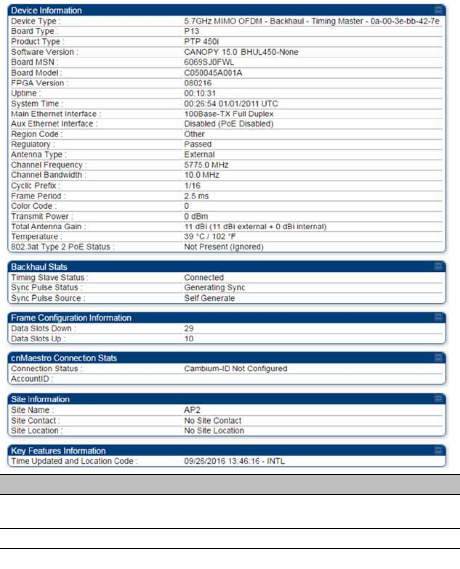
Chapter 9: Operation System information
Page 9-15
General Status page of BHM
The BHM’s General Status page is explained in Table 197.
Table 197 General Status page attributes - BHM
Attribute Meaning
Device Type This field indicates the type of the module. Values include the frequency
band of the BHM, its module type and its MAC address.
Board Type This field indicates the series of hardware.
Product Type This indicates model of the device.

Chapter 9: Operation System information
Page 9-16
Software Version This field indicates the system release, the time and date of the release.
If you request technical support, provide the information from this field.
Board MSN This field indicates the Manufacture’s Serial number. A unique serial
number assigned to each radio at the factory for inventory and quality
control.
FPGA Version This field indicates the version of the field-programmable gate array
(FPGA) on the module. When you request technical support, provide the
information from this field.
Uptime This field indicates how long the module has operated since power was
applied.
System Time This field provides the current time. Any BHS that registers to a BHM
inherits the system time, which is displayed in this field as GMT
(Greenwich Mean Time).
Ethernet Interface This field indicates the speed and duplex state of Ethernet interface to
the BHM.
Antenna Type The current antenna type that has been selected.
Temperature The current operating temperature of the board.
Session Status
This field displays the following information about the current session:
Scanning indicates that this BHS currently cycles through the radio
frequencies that are selected in the Radio tab of the Configuration page.
Syncing indicates that this BHM currently attempts to receive sync.
Registering indicates that this BHM has sent a registration request
message to the BHM and has not yet received a response.
Registered indicates that this BHM is both:
Registered to a BHM.
Ready to transmit and receive data packets.
Session Uptime This field displays the duration of the current link. The syntax of the
displayed time is hh:mm:ss.
Registered Backhaul Displays the MAC address and site name of the BHM to which the BHS is
registered to. This parameter provides click-through proxy access to the
BHM’s management interface.
Channel Frequency This field lists the current operating frequency of the radio.
Receive Power This field lists the current combined receive power level, in dBm.
Signal Strength
Ratio
This field displays the difference of the Vertical path received signal
power to the Horizontal path received signal power.
Transmit Power This field lists the current combined transmit power level, in dBm.

Chapter 9: Operation System information
Page 9-17
Signal to Noise Ratio This field lists the current signal-to-noise level, an indication of the
separation of the received power level vs. noise floor.
Beacons Displays a count of beacons received by the BHM in percentage. This
value must be typically between 99-100%. If lower than 99%, it indicates
a problematic link. This statistic is updated every 16 seconds.
Air Delay This field displays the distance in feet between this BHS and the BHM.
To derive the distance in meters, multiply the value of this parameter by
0.3048. Distances reported as less than 200 feet (61 meters) are
unreliable.
Data Slots Down This field lists the number of slots used for downlink data transmission.
Data Slots Up This field lists the number of slots used for uplink data transmission.
Regional Code
A parameter that offers multiple fixed selections, each of which
automatically implements frequency band range restrictions for the
selected region. Units shipped to regions other than the United States
must be configured with the corresponding Country Code to comply
with local regulatory requirements.
Site Name This field indicates the name of the physical module. Assign or change
this name in the Configuration > SNMP page. This information is also set
into the sysName SNMP MIB-II object and can be polled by an SNMP
management server.
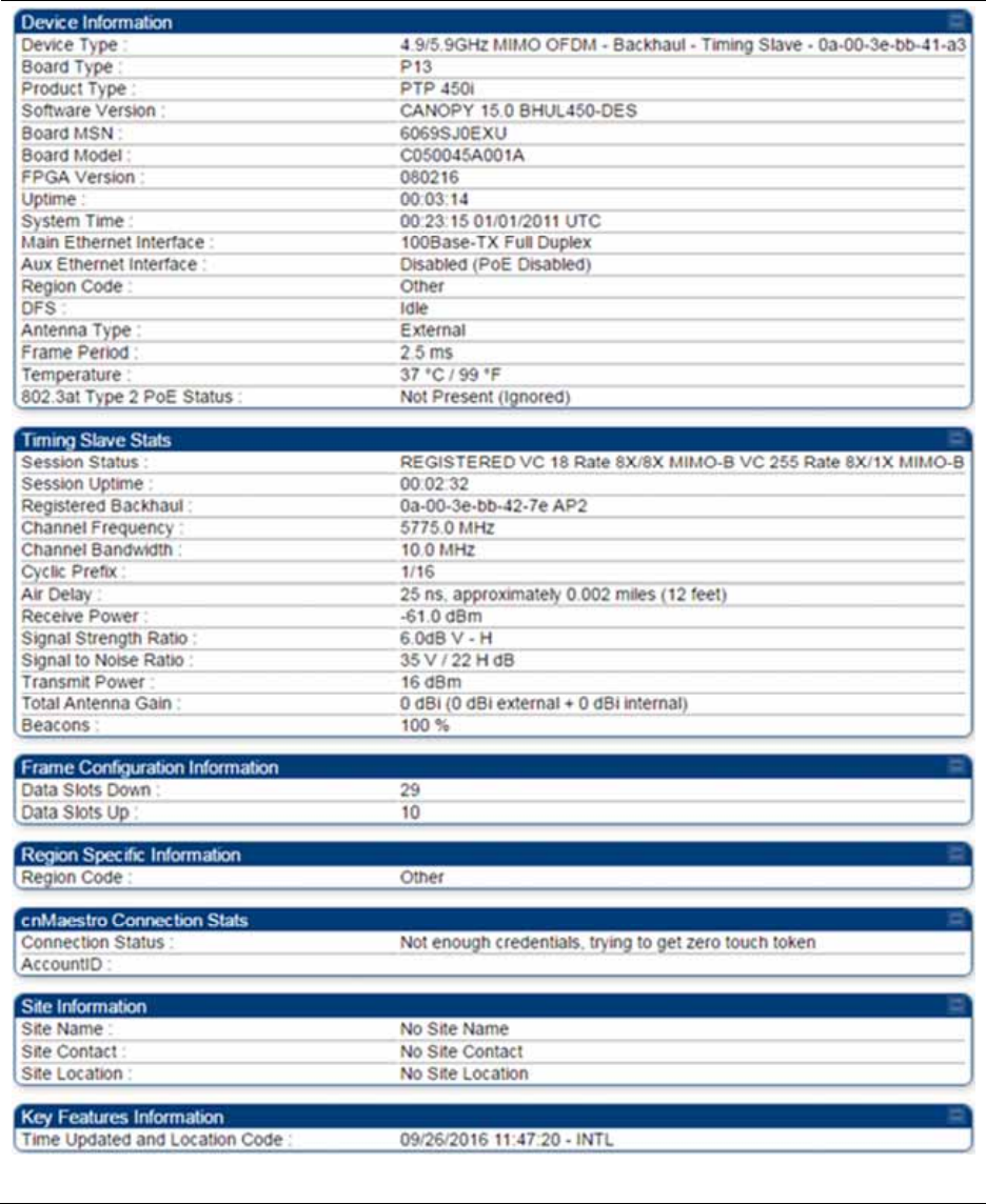
Chapter 9: Operation System information
Page 9-18
General Status page of BHS
The BHS’s General Status page is explained in Table 198.
Table 198 General Status page attributes - BHS

Chapter 9: Operation System information
Page 9-19
Attribute Meaning
Device Type
See Table 198 on page 9-18
Board Type
Software Version
Board MSN
FPGA Version
Uptime
See Table 198 on page 9-18
System Time
Ethernet Interface
Antenna Type
Temperature
Session Status
Session Uptime
Registered Backhaul
Channel Frequency
Receive Power
Signal Strength
Ratio
Transmit Power
Signal to Noise Ratio
Beacons
Air Delay
Data Slots Down
Data Slots Up
Regional Code
Site Name
Site Contact
Site Location
Time Updated and
Location Code
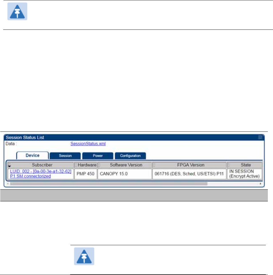
Chapter 9: Operation System information
Page 9-20
Viewing Session Status
The Session Status page in the Home page provides information about each SM or BHS that has
registered to the AP or BHM. This information is useful for managing and troubleshooting a
system. This page also includes the current active values on each SM or BHS for MIR and VLAN, as
well as the source of these values, representing the SM/BHS itself, Authentication Server, or the
Authentication Server and SM/BHS.
Note
In order for accurate power level readings to be displayed, traffic must be present on
the radio link.
The Session Status List has four tab: Device, Session, Power and Configuration.
The SessionStatus.xml hyper link allows user to export session status page from web
management interface of AP or BHM. The session status page will be exported in xml file.
Device tab
The Device tab provides information on the Subscriber’s LUID and MAC, Hardware, Software,
FPGA versions and the state of the SM/BHS (Registered and/or encrypted).
Table 199 Device tab attributes
Attribute Meaning
Subscriber This field displays the LUID (logical unit ID), MAC address and Site Name
of the SM/BHS. As each SM or BHS registers to the AP/BHM, the system
assigns an LUID of 2 or a higher unique number to the SM/BHS. If a
SM/BHS loses registration with the AP/BHS and then regains
registration, the SM/BHS will retain the same LUID.
Note
The LUID associated is lost when a power cycle of the
AP/BHM occurs.
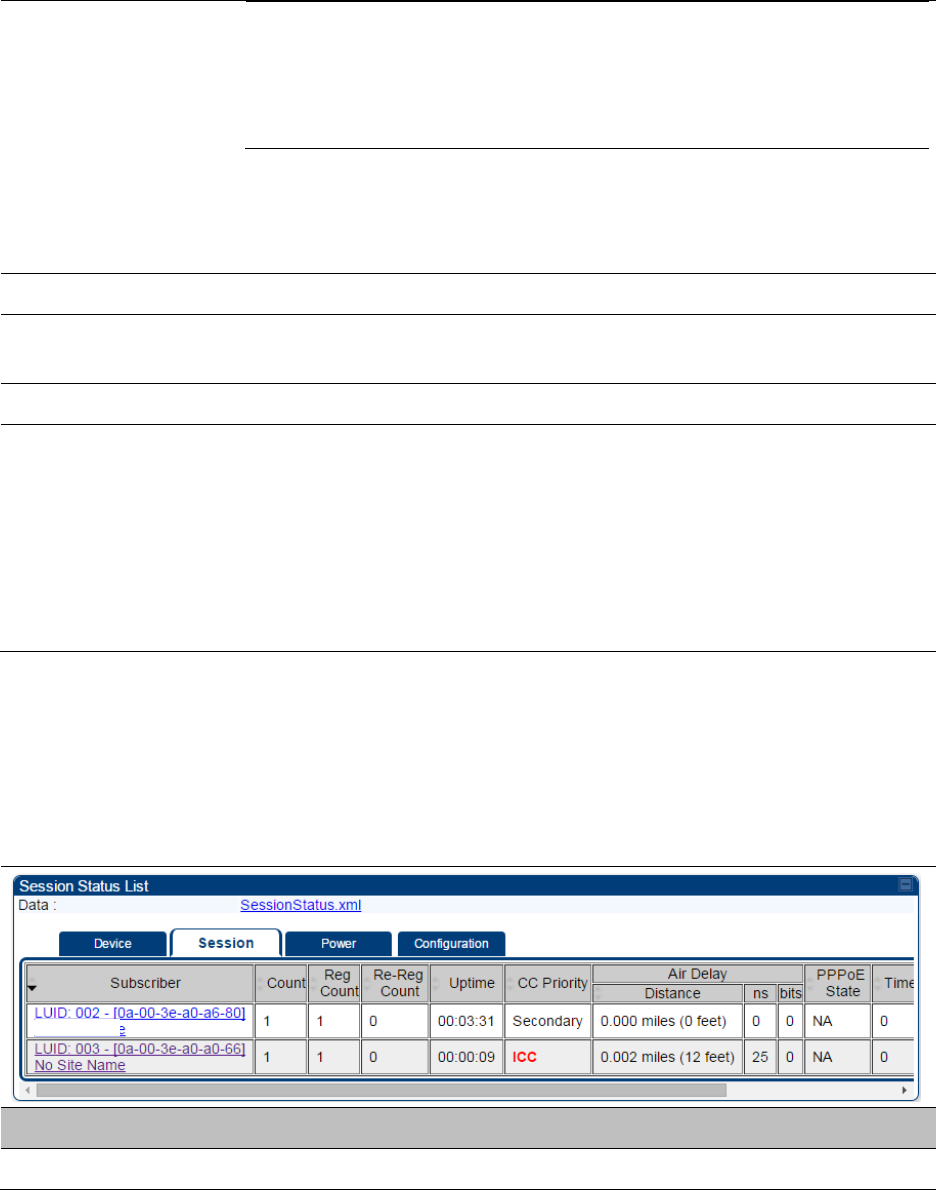
Chapter 9: Operation System information
Page 9-21
Both the LUID and the MAC are hot links to open the
interface to the SM/BHS. In some instances, depending on
network activity and network design, this route to the
interface yields a blank web page. If this occurs, refresh
your browser view.
Site Name indicates the name of the SM/BHS. Change this name on the
Configuration web page of the SM/BHS. This information is also set into
the sysName SNMP MIB-II object and can be polled by an SNMP
management server.
Hardware This field displays the SMs or BHS hardware type.
Software Version This field displays the software release that operates on the SM/BHS, the
release date and time of the software.
FPGA Version This field displays the version of FPGA that runs on the SM/BHS
State
This field displays the current status of the SM/BHS as either
IN SESSION to indicate that the SM/BHS is currently registered to
the AP/BHM.
IDLE to indicate that the SM/BHS was registered to the AP/BHM at
one time, but now is not.
This field also indicates whether the encryption scheme in the module is
enabled.
Session tab
The Session tab provides information on the SMs or BHS Session Count, Reg Count, Re-Reg
Count, Uptime, Air delay, PPPoE State and Timeouts.
Table 200 Session tab attributes
Attribute Meaning
Subscriber See Table 199 on page 9-20.
Chapter 9: Operation System information
Page 9-22
Count This field displays how many sessions the SM/BHS has had with the
AP/BHM. Typically, this is the sum of Reg Count and Re-Reg Count.
However, the result of internal calculation may display here as a value
that slightly differs from the sum.
If the number of sessions is significantly greater than the number for
other SMs or BHS, then this may indicate a link problem or an
interference problem.
Reg Count When a SM/BHS makes a Registration Request, the AP/BHM checks its
local session database to see whether it was registered earlier. If the
AP/BHM concludes that the SM/BHS is not currently in session database
and it is valid Registration Request, then the request increments the
value of this field.
In ideal situation, the Reg Count indicates total number of connected
SMs to an AP.
Note
The user can clear Reg Count by dropping all current
sessions of SM (or BHS) from Configuration > Tools >
Sessions menu.
Re-Reg Count
When a SM/BHS makes a Registration Request, the AP/BHM checks its
local session database to see whether it was registered earlier. If the
AP/BHM concludes that the SM/BHS is currently in session database,
then the request increments the value of this field.
Typically, a Re-Reg is the case where both:
SM/BHS attempts to reregister for having lost communication with
the AP/BHM.
AP/BHM has not yet observed the link to the SM/BHS as being down.
It is possible for a small period of time if there is no downlink traffic and
AP/BHM still assumes the session is up, but the SM/BHS, loses session
and quickly re-connects before the AP/BHM knew the session had
dropped. This is how a re-registration happens.
If the number of sessions is significantly greater than the number for
other SMs or BHS, then this may indicate a link problem (check
mounting, alignment, receive power levels) or an interference problem
(conduct a spectrum scan).
Uptime Once a SM/BHS successfully registers to an AP/BHM, this timer is
started. If a session drops or is interrupted, this timer is reactivated once
re-registration is complete.
CC Priority The field displays Color Code Priority (ICC, Primary, Secondary or
Tertiary) of all connected SM.
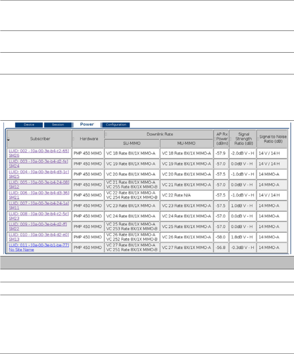
Chapter 9: Operation System information
Page 9-23
AirDelay This field displays the distance of the SM/BHS from the AP/BHM in
meters, nanoseconds and bits. At close distances, the value in this field
is unreliable.
PPPoE state This field displays the current PPPoE state (whether configured) of the
SM/BHS.
Timeout This field displays the timeout in seconds for management sessions via
HTTP, ftp access to the SM/BHS. 0 indicates that no limit is imposed.
Power tab
Table 201 Power tab attributes
Attribute Meaning
Subscriber See Table 199 on page 9-20.
Hardware This field displays the SMs or BHS hardware type.
Downlink Rate SU-
MIMO
This field displays whether the high-priority channel is enabled in the
SM/BHS and the status of rate adapt. For example, if “8X/4X” is listed,
the radio is capable of operating at 8X but is currently operating at 4X,
due to RF conditions.
This field also states whether it is MIMO-A or MIMO-B radio e.g. “8X/8X
MIMO-B” indicates MIMO-B and “8X/4X MIMO-A” indicates MIMO-A.
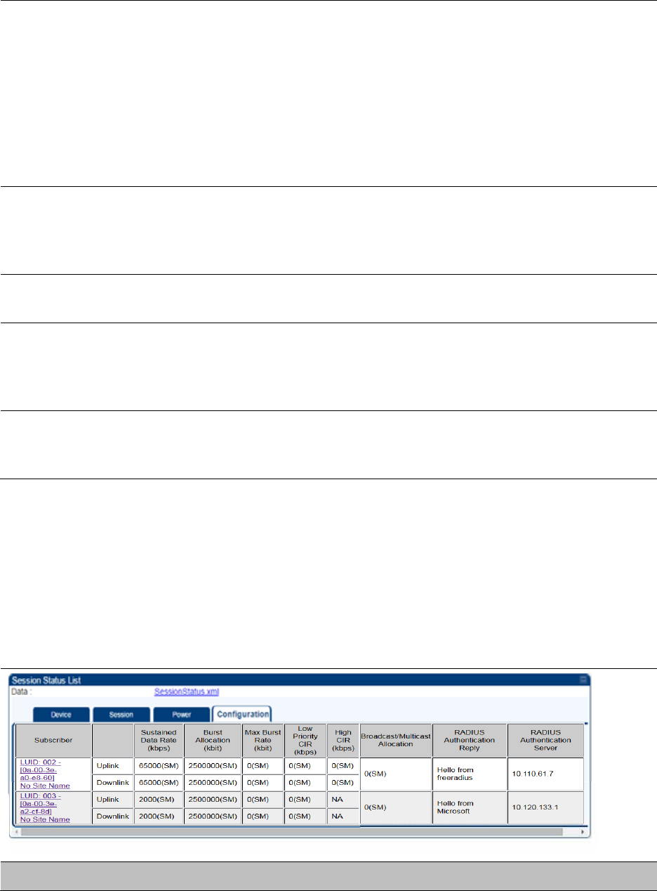
Chapter 9: Operation System information
Page 9-24
A VC starts at its lowest modulation and slowly rate adapts up, as traffic
is successfully transmitted over the VC. It is normal for one VC to have a
different modulation rate than another VC, if only one VC has traffic on
it. For example if High Priority VC is enabled, but only low priority VC
has traffic the reading will show:
REGISTERED VC 18 Rate 8X/8X MIMO-B VC 255 Rate 8X/1X MIMO-B
Note: The SU-MIMO rate applies to all AP platforms. For 450m, this field
indicates the rate being used for symbols where this particular VC is not
being MU-MIMO grouped with other SM’s.
Downlink Rate MU-
MIMO
The MU-MIMO rate applies only to the 450m AP. This rate indicates the
modulation used for symbols where this particular low priority VC is
MU-MIMO scheduled, by grouping it in the same slot with other low
priority VC’s
AP Rx Power (dBm) This field indicates the AP’s or BHM’s combined receive power level for
the listed SM/BHS.
Signal Strength
Ratio (dB)
This field displays the ratio of the Vertical path received signal power to
the Horizontal path received signal power. This ratio can be useful for
determining multipathing conditions (high vertical to horizontal ratio) for
Uplink.
Signal to Noise Ratio
(dB)
This field lists the current signal-to-noise level, an indication of the
separation of the received power level vs. noise floor. In other words, it
indicates signal to noise ratio for Uplink.
Configuration tab
The Configuration tab provides information on the SMs or BHS Uplink or Downlink (UL/DL)
Sustained Data Rate, UL/DL Burst Allocation, UL/DL Burst Rate, UL/DL Low Priority CIR, UL/DL High
CIR, UL/DL High Priority Queue Information and the UL/DL Broadcast or Multicast Allocation. This
data is refreshed based on the Web Page Auto Update setting on the AP’s or BHS’s General
Configuration page.
Table 202 Configuration tab attributes
Attribute Meaning

Chapter 9: Operation System information
Page 9-25
Subscriber See Table 199 on page 9-20.
Sustained Data Rate
(kbps) - Uplink
This field displays the value that is currently in effect for the SM/BHS,
with the source of that value in parentheses. This is the specified rate at
which each SM/BHS registered to this AP/BHM is replenished with
credits for transmission. The configuration source of the value is
indicated in parentheses.
See Maximum Information Rate (MIR) Parameters on page 7-187.
Sustained Data Rate
(kbps) - Downlink
This field displays the value that is currently in effect for the SM/BHS,
with the source of that value in parentheses. This is the specified the rate
at which the AP/BHM should be replenished with credits (tokens) for
transmission to each of the SMs/BHS’s in its sector. The configuration
source of the value is indicated in parentheses.
See Maximum Information Rate (MIR) Parameters on page 7-187.
Burst Allocation
(kbit) - Uplink
This field displays the value that is currently in effect for the SM/BHS,
with the source of that value in parentheses. This is the specified
maximum amount of data that each SM/BHS is allowed to transmit
before being recharged at the Sustained Uplink Data Rate with credits to
transmit more. The configuration source of the value is indicated in
parentheses.
See Interaction of Burst Allocation and Sustained Data Rate Settings on
page 7-189
Burst Allocation
(kbit) - Downlink
This field displays the value that is currently in effect for the SM/BHS,
with the source of that value in parentheses. This is the specified the rate
at which the AP/BHM should be replenished with credits (tokens) for
transmission to each of the SMs/BHS’s in its sector. The configuration
source of the value is indicated in parentheses.
See Interaction of Burst Allocation and Sustained Data Rate Settings on
page 7-189
Max Burst Rate (kbit)
- Uplink
The data rate at which an SM/BHS is allowed to burst (until burst
allocation limit is reached) before being recharged at the Sustained
Uplink Data Rate with credits to transit more. When set to 0 (default), the
burst rate is unlimited.
See Interaction of Burst Allocation and Sustained Data Rate Settings on
page 7-189
Max Burst Rate (kbit)
- Downlink
The data rate at which an SM/BHS is allowed to burst (until burst
allocation limit is reached) before being recharged at the Sustained
Downlink Data Rate with credits to transit more. When set to 0 (default),
the burst rate is unlimited.
See Interaction of Burst Allocation and Sustained Data Rate Settings on
page 7-189

Chapter 9: Operation System information
Page 9-26
Low Priority CIR This field indicates the minimum rate at which low priority traffic is sent
over the uplink and downlink (unless CIR is oversubscribed or RF link
quality is degraded).
High CIR This field indicates the minimum rate at which high priority traffic is sent
over the uplink and downlink (unless CIR is oversubscribed or RF link
quality is degraded).
Broadcast/Multicast
Allocation
This field displays the data rate at which Broadcast and Multicast traffic
is sent via the radio link.
RADIUS
Authentication Reply
This field displays whether RADIUS server is reachable or not.
RADIUS
Authentication
Server
This field displays the associated RADIUS Authentication Server for each
SM where it was authenticated. This information is useful when there
are multiple RADIUS servers (maximum three servers supported by
Cambium). If one server is not reachable, other configured servers are
tried in sequential order as a fall-back. In this scenario, the Session
Status is useful to identify associate RADIUS Authentication Server for
all connected SMs.
Table 203 Session Status > Configuration CIR configuration denotations
Attribute Meaning
(SM) QoS/VLAN parameters are derived from the SM’s/BHS’s settings
(APCAP) QoS/VLAN parameters are derived from the AP’s settings, including any
keyed capping (for radios capped at 4 Mbps, 10 Mbps, or 20 Mbps)
(D) QoS/VLAN parameters are retrieved from the device, due to failed
retrieval from the AAA or WM server.
(AAA) QoS/VLAN parameters are retrieved from the RADIUS server
(BAM) QoS/VLAN parameters are retrieved from a WM BAM server
Chapter 9: Operation System information
Page 9-27
Viewing Remote Subscribers
This page allows to view the web pages of registered SMs or BHS over the RF link. To view the
pages for a selected SM/BHS, click its link. The General Status page of the SM opens.
Figure 178 Remote Subscribers page of AP
Interpreting messages in the Event Log
Each line in the Event Log of a module Home page begins with a time and date stamp. However,
some of these lines wrap as a combined result of window width, browser preferences and line
length. You may find this tab easiest to use if you expand the window till all lines are shown
beginning with time and date stamp.
Time and Date Stamp
The time and date stamp reflect one of the following:
GPS time and date directly or indirectly received from the CMM4.
NTP time and date from a NTP server (CMM4 may serve as an NTP server)
The running time and date that you have set in the Time & Date web page.
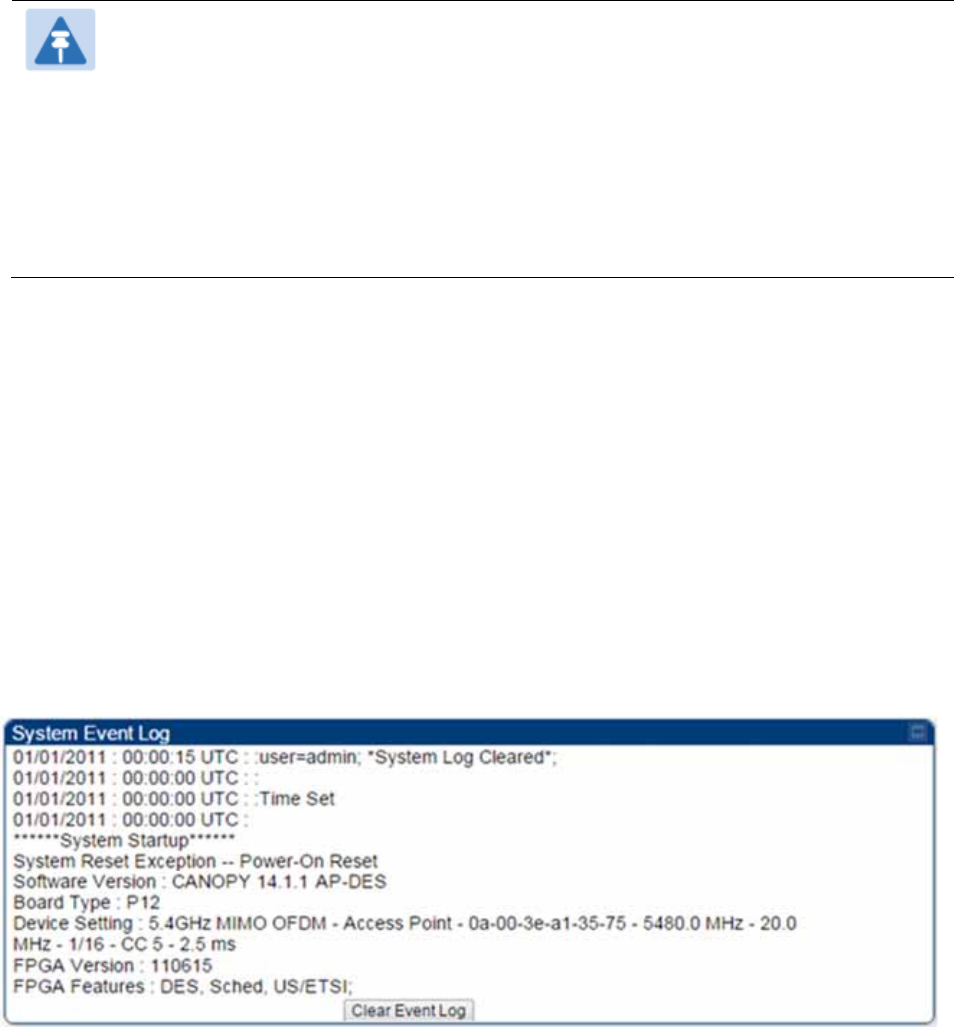
Chapter 9: Operation System information
Page 9-28
Note
In the Time & Date web page, if you have left any time field or date field unset and
clicked the Set Time and Date button, then the time and date default to 00:00:00 UT
: 01/01/00.
A reboot causes the preset time to pause or, in some cases, to run in reverse.
Additionally, a power cycle resets the running time and date to the default 00:00:00
UT : 01/01/00. Thus, whenever either a reboot or a power cycle has occurred,
must reset the time and date in the Time & Date web page of any module that is not
set to receive sync.
Event Log Data Collection
The collection of event data continues through reboots and power cycles. When the buffer
allowance for event log data is reached, the system adds new data into the log and discards an
identical amount of the oldest data.
Each line that contains the expression WatchDog flags an event that was both:
considered by the system software to have been an exception
recorded in the preceding line.
Conversely, a Fatal Error () message flags an event that is recorded in the next line. Some
exceptions and fatal errors may be significant and require either operator action or technical
support.
Figure 179 Event log data

Chapter 9: Operation System information
Page 9-29
Messages that Flag Abnormal Events
The messages listed below flag abnormal events and, case by case, may signal the need for
corrective action or technical support.
Table 204 Event Log messages for abnormal events
Event Message Meaning
Expected LUID = 6
Actual LUID = 7
Something is interfering with the control messaging of the module. Also
ensure that you are using shielded cables to minimize interference.
Consider trying different frequency options to eliminate or reduce
interference.
FatalError() The event recorded on the line immediately beneath this message
triggered the Fatal Error ().
Loss of GPS Sync
Pulse Module has lost GPS sync signal.
Machine Check
Exception
This is a symptom of a possible hardware failure. If this is a recurring
message, begin the RMA process for the module.
RcvFrmNum =
0x00066d
ExpFrmNum =
0x000799
Something is interfering with the control messaging of the module. Also
ensure that you are using shielded cables to minimize interference.
Consider trying different frequency options to eliminate or reduce
interference.
System Reset
Exception -- External
Hard Reset
The unit lost power or was power cycled.
System Reset
Exception -- External
Hard Reset
WatchDog
The event recorded on the preceding line triggered this WatchDog
message.
Messages that Flag Normal Events
The messages listed below record normal events and typically do not signal a need for any
corrective action or technical support.
Table 205 Event Log messages for normal events
Event Message Meaning
Acquired GPS Sync
Pulse. Module has acquired GPS sync signal.
FPGA Features Type of encryption.
FPGA Version FPGA (JBC) version in the module.
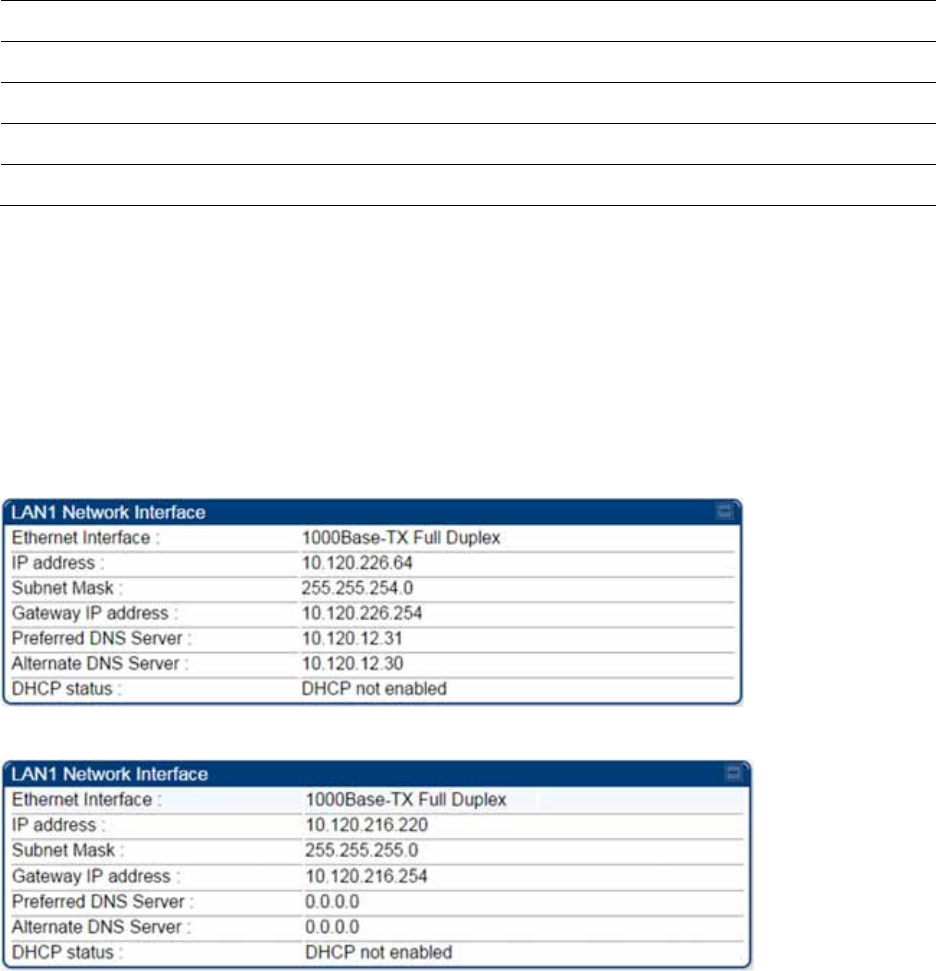
Chapter 9: Operation System information
Page 9-30
GPS Date/Time Set Module is now on GPS time.
Reboot from Webpage Module was rebooted from management interface.
Software Boot Version Boot version in the module.
Software Version The software release and authentication method for the unit.
System Log Cleared Event log was manually cleared.
Viewing the Network Interface
In any module, the LAN1 Network Interface section of this tab displays the defined Internet
Protocol scheme for the Ethernet interface to the module. In SM/BHS devices, this page also
provides an RF Public Network Interface section, which displays the Internet Protocol scheme
defined for network access through the master device (AP/BHM).
Figure 180 Network Interface tab of the AP
Figure 181 Network Interface tab of the SM
Chapter 9: Operation System information
Page 9-31
Viewing the Layer 2 Neighbors
In the Layer 2 Neighbors tab, a module reports any device from which it has received a message in
Link Layer Discovery Protocol within the previous two minutes. Given the frequency of LLDP
messaging, this means that the connected device will appear in this tab 30 seconds after it is
booted and remain until two minutes after its shutdown.
Figure 182 Layer 2 Neighbors page
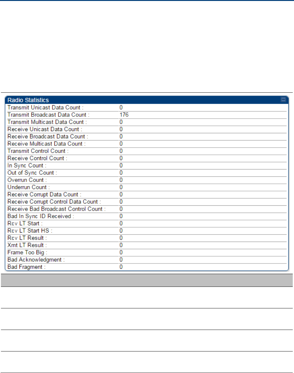
Chapter 9: Operation System statistics
Page 9-32
System statistics
This section describes how to use the system statistics pages to manage the performance of the
PMP/PTP 450 Platform Family link.
Viewing the Scheduler statistics
The Statistics > Scheduler page is applicable for all modules (AP/SM/BHM/BHS) and the
parameters are displayed as shown below:
Table 206 Scheduler tab attributes
Attribute Meaning
Transmit Unicast
Data Count Total amount of unicast packets transmitted from the radio
Transmit Broadcast
Data Count Total amount of broadcast packets transmitted from the radio
Transmit Multicast
Data Count Total amount of multicast packets transmitted by the radio
Receive Unicast Data
Count Total amount of unicast packets received by the radio

Chapter 9: Operation System statistics
Page 9-33
Receive Broadcast
Data Count Total amount of broadcast packets received by the radio
Receive Multicast
Data Count Total amount of multicast packets received by the radio
Transmit Control
Count
Amount of radio control type messages transmitted (registration
requests and grants, power adjust, etc.)
Receive Control
Count
Amount of radio control type messages received (registration requests
and grants, power adjust, etc.)
In Sync Count Number of times the radio has acquired sync. When GPS
synchronization is used it is number of times GPS sync acquired. For the
SM, itis the number of times the SM successfully obtained sync with an
AP.
Out of Sync Count Number of times the radio lost same sync lock
Overrun Count Number of times FPGA frame has overrun its TX Frame
Underrun Count Number of times FPGAs TX Frame aborted prematurely
Receive Corrupt Data
Count Number of times a corrupt fragment has been received at the FPGA.
Receive Bad
Broadcast Control
Count
Number of times the radio has received an invalid control message via
broadcast (SM only).
Bad In Sync ID
Received Currently unused
Rcv LT Start Number of Link Test Start messages received. A remote radio has
requested that this radio start a link test to it.
Rcv LT Start HS Number of Link Test Start Handshake messages received. This radio
requested that a remote radio start a link test and the remote radio has
sent a handshake back acknowledging the start.
Rcv LT Result This radio received Link Test results from the remote radio under
test. When this radio initiates a link test, the remote radio will send its
results to this radio for display.
Xmt LT Result This radio transmitted its link test results to the remote radio under
test. When the remote radio initiates a link test, this radio must send its
results to the remote radio for display there.
Frame Too Big This statistics indicates the number of packets received and processed
by the radios which were greater than max packet size 1700 bytes.
Bad
Acknowledgment
This statistics indicates the number of packets received as bad
acknowledgment. It is for engineering use only.
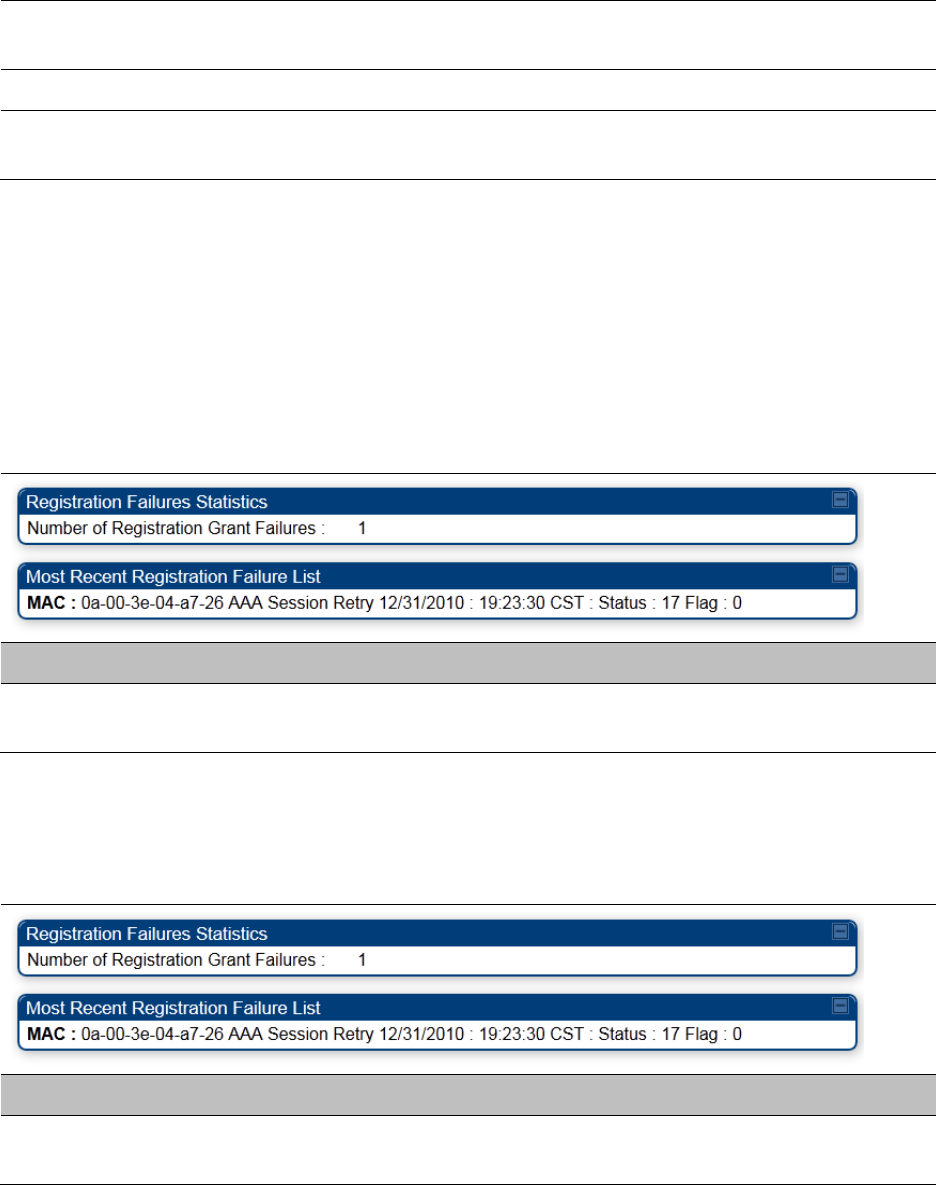
Chapter 9: Operation System statistics
Page 9-34
Bad Fragment This statistic indicates number of fragments tagged internally as bad. It
is for engineering use only.
Rx No Buffer Count Currently unused
Scheduler Error This error is incremented when the scheduler cannot send or get
scheduled to send a packet. t is also general called a “VC Error”.
Viewing list of Registration Failures statistics
SM Registration Failures page of AP
The SM Registration Failures tab identifies SMs that have recently attempted and failed to register
to this AP. With its time stamps, these instances may suggest that a new or transient source of
interference exists.
Table 207 SM Registration Failures page attributes - AP
Attribute Meaning
Status 17 Flag 0 No response was received from the AAA server and hence SM is trying
to send a session request again.
BHS Registration Failures page of BHM
Table 208 BHS Registration Failures page attributes - BHM
Attribute Meaning
Status 17 Flag 0 No response was received from the AAA server and hence SM is trying
to send a session request again.
There is a list of flags from 0 to 20 as shown in Table 209 and the “Flags” can be ignored.

Chapter 9: Operation System statistics
Page 9-35
Table 209 Flags status
Flag Meaning Flag Meaning
0 Normal 11 AP Lite Limit Reached
1 Out of Range 12 Only Ver 9.5+ Allowed
2 No Luids 13 Temporary Data VC for AAA
3 BH ReRange 14 AAA Authentication Failure
4 Auth Fail 15 Registration Grant Reject
5 Encrypt Fail 16 Blank
6 Power Adjust 17 AAA Session Retry
7 No VCs 18 AAA Reauth Failure
8 Reserve VC Fail 19 RegReq at zero power
9 Activate VC Fail 20 RegReq no time ref
10 Hi VC Setup Fail - -
Interpreting Bridging Table statistics
If NAT (network address translation) is not active on the SM/BHS, then the Bridging Table page
provides the MAC address of all devices that are attached to registered SMs/BHS (identified by
LUIDs).
The SM/BHS management MAC addresses are also added in bridge table upon SMs/BHS
registration. These entries will be remove automically from the table once SMs/BHS is de-
registered. This alleviates the arp cache > bridge cache timeout problems.
The bridging table allows data to be sent to the correct module as follows:
For the AP/BHM, the uplink is from RF to Ethernet. Thus, when a packet arrives in the RF
interface to the AP/BHM, the AP/BHM reads the MAC address from the inbound packet and
creates a bridging table entry of the source MAC address on the other end of the RF interface.
For the SM/BHS, the uplink is from Ethernet to RF. Thus, when a packet arrives in the Ethernet
interface to one of these modules, the module reads the MAC address from the inbound packet
and creates a bridging table entry of the source MAC address on the other end of the Ethernet
interface.
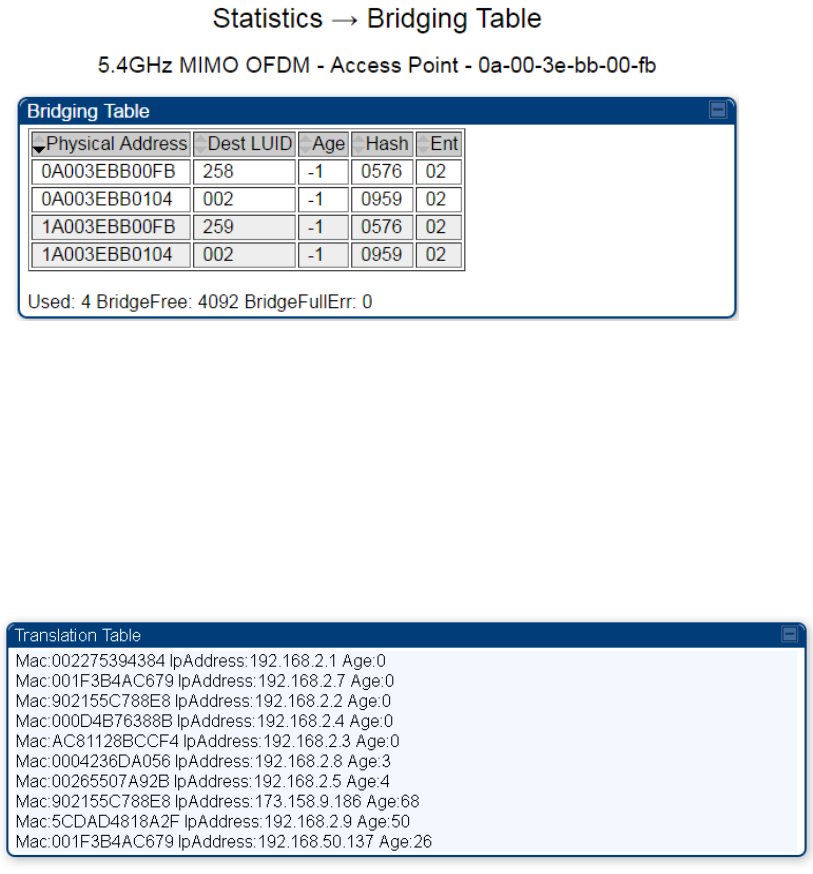
Chapter 9: Operation System statistics
Page 9-36
Figure 183 Bridging Table page
The Bridging Table supports up to 4096 entries.
Interpreting Translation Table statistics
When Translation Bridging is enabled in the AP, each SM keeps a table mapping MAC addresses
of devices attached to the AP to IP addresses, as otherwise the mapping of end-user MAC
addresses to IP addresses is lost. (When Translation Bridging is enabled, an AP modifies all uplink
traffic originating from registered SMs such that the source MAC address of every packet is
changed to that of the SM which bridged the packet in the uplink direction.)
Figure 184 Translation Table page of SM
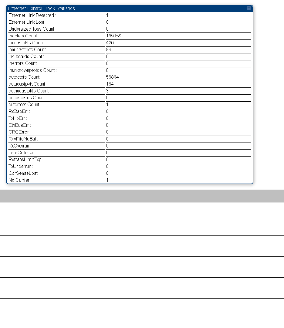
Chapter 9: Operation System statistics
Page 9-37
Interpreting Ethernet statistics
The Statistics > Ethernet page reports TCP throughput and error information for the Ethernet
connection of the module. This page is applicable for all modules (AP/SM/BHM/BHS).
The Ethernet page displays the following fields.
Table 210 Ethernet tab attributes
Attribute Meaning
Ethernet Link
Detected
1 indicates that an Ethernet link is established to the radio, 0 indicates
that no Ethernet link is established
Ethernet Link Lost This field indicates a count of how many times the Ethernet link was lost.
Undersized Toss
Count
This field indicates the number of packets that were too small to process
and hence discarded.
inoctets Count This field displays how many octets were received on the interface,
including those that deliver framing information.
inucastpkts Count This field displays how many inbound subnetwork-unicast packets were
delivered to a higher-layer protocol.
Innucastpkts Count This field displays how many inbound non-unicast (subnetwork-
broadcast or subnetwork-multicast) packets were delivered to a higher-
layer protocol.

Chapter 9: Operation System statistics
Page 9-38
indiscards Count This field displays how many inbound packets were discarded without
errors that would have prevented their delivery to a higher-layer
protocol. (Some of these packets may have been discarded to increase
buffer space.)
inerrors Count This field displays how many inbound packets contained errors that
prevented their delivery to a higher-layer protocol.
inunknownprotos
Count
This field displays how many inbound packets were discarded because
of an unknown or unsupported protocol.
outoctets Count This field displays how many octets were transmitted out of the
interface, including those that deliver framing information.
outucastpkts Count This field displays how many packets for which the higher-level
protocols requested transmission to a subnetwork-unicast address. The
number includes those that were discarded or not sent.
outnucastpkts Count This field displays how many packets for which the higher-level
protocols requested transmission to a non-unicast (subnetwork-
broadcast or subnetwork-multicast) address. The number includes those
that were discarded or not sent.
outdiscards Count This field displays how many outbound packets were discarded without
errors that would have prevented their transmission. (Some of these
packets may have been discarded to increase buffer space.)
outerrrors Count This field displays how many outbound packets contained errors that
prevented their transmission.
RxBabErr This field displays how many receiver babble errors occurred.
TxHbErr This field displays how many transmit heartbeat errors have occurred.
EthBusErr This field displays how many Ethernet bus errors occurred on the
Ethernet controller.
CRCError This field displays how many CRC errors occurred on the Ethernet
controller.
RcvFifoNoBuf This field displays the number of times no FIFO buffer space was able to
be allocated
RxOverrun This field displays how many receiver overrun errors occurred on the
Ethernet controller.
Late Collision
This field displays how many late collisions occurred on the Ethernet
controller. A normal collision occurs during the first 512 bits of the frame
transmission. A collision that occurs after the first 512 bits is considered
a late collision.

Chapter 9: Operation System statistics
Page 9-39
Caution
A late collision is a serious network problem because the frame
being transmitted is discarded. A late collision is most commonly
caused by a mismatch between duplex configurations at the ends
of a link segment.
RetransLimitExp This field displays how many times the retransmit limit has expired.
TxUnderrun This field displays how many transmission-underrun errors occurred on
the Ethernet controller.
CarSenseLost This field displays how many carrier sense lost errors occurred on the
Ethernet controller.
No Carrier This field displays how many no carrier errors occurred on the Ethernet
controller.
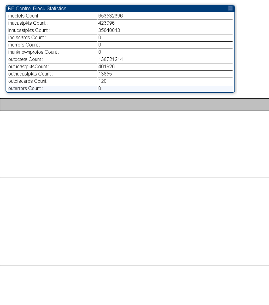
Chapter 9: Operation System statistics
Page 9-40
Interpreting RF Control Block statistics
The Statistics > Radio page is applicable for all module (AP/SM/BHM/BHS). The Radio page of the
Statistics page displays the following fields.
Table 211 Radio (Statistics) page attributes – RF Control Block
Attribute Meaning
inoctets Count This field displays how many octets were received on the interface,
including those that deliver framing information.
inucastpkts Count This field displays how many inbound subnetwork-unicast packets were
delivered to a higher-layer protocol.
Innucastpkts Count This field displays how many inbound non-unicast (subnetwork-
broadcast or subnetwork-multicast) packets were delivered to a higher-
layer protocol.
indiscards Count This field displays how many inbound packets were discarded without
errors that would have prevented their delivery to a higher-layer
protocol. This stat is pegged whenever corrupt data is received by
software or whenever the RF Software Bridge queue is full.
Corrupt data is a very unusual event because all packets are CRC
checked by hardware before being passed into software.
The likely case for indiscards is if the RF bridge queue is full. If this is the
case the radio is most likely PPS limited due to excessive small packet
traffic or a problem at the Ethernet interface. If there is a problem at the
Ethernet interface there is likely to be discards at the Ethernet as well.
inerrors Count This field displays how many inbound packets contained errors that
prevented their delivery to a higher-layer protocol.
inunknownprotos
Count
This field displays how many inbound packets were discarded because
of an unknown or unsupported protocol.

Chapter 9: Operation System statistics
Page 9-41
outoctets Count This field displays how many octets were transmitted out of the
interface, including those that deliver framing information.
outucastpkts Count This field displays how many packets for which the higher-level
protocols requested transmission to a subnetwork-unicast address. The
number includes those that were discarded or not sent.
outnucastpkts Count This field displays how many packets for which the higher-level
protocols requested transmission to a non-unicast (subnetwork-
broadcast or subnetwork-multicast) address. The number includes those
that were discarded or not sent.
outdiscards Count This field displays how many outbound packets were discarded without
errors that would have prevented their transmission. (Some of these
packets may have been discarded to increase buffer space.)
outerrrors Count This field displays how many outbound packets contained errors that
prevented their transmission.
Chapter 9: Operation System statistics
Page 9-42
Interpreting Sounding statistics
In the SM GUI, sounding statistics can be found under Statistics > Radio.
The top section, RF Control Block Statistics, is applicable to the SM communicating to any AP (450,
450i, or 450m), and it is always visible. The bottom section, Sounding Statistics, is visible only if
the SM is communicating with a 450m AP.
Table 212 Radio (Statistics) page attributes - Sounding
Attribute Meaning
Responses Number of sounding responses (full VC assessments or condensed
nulling) sent from the SM to the AP
Responses
Suppressed
Number of sounding requests suppressed by the SM.
The reason why a sounding response is suppressed is because the error
calculated during the sounding process is lower that the threshold set by
the AP. In this case, the SM does not need to transmit a sounding
response to the AP
Errors Number of errors in the sounding process at the SM
Examples of events that count as errors:
Sounding type is not supported
IQ capture not enabled: for example, if sounding requested too soon
after SM boot
IQ capture did not complete
Sounding processing took too long
Version Mismatch Number of sounding requests with mismatched version numbers
The Sounding Acquisition Command contains a version number. The
SM checks its own version number and flags any mismatch. Currently,
AP and SMs use V1.
Max Request Interval Largest time between two sounding requests received from the 450m AP
Avg Request Interval Average time between two sounding requests received from the 450m
AP
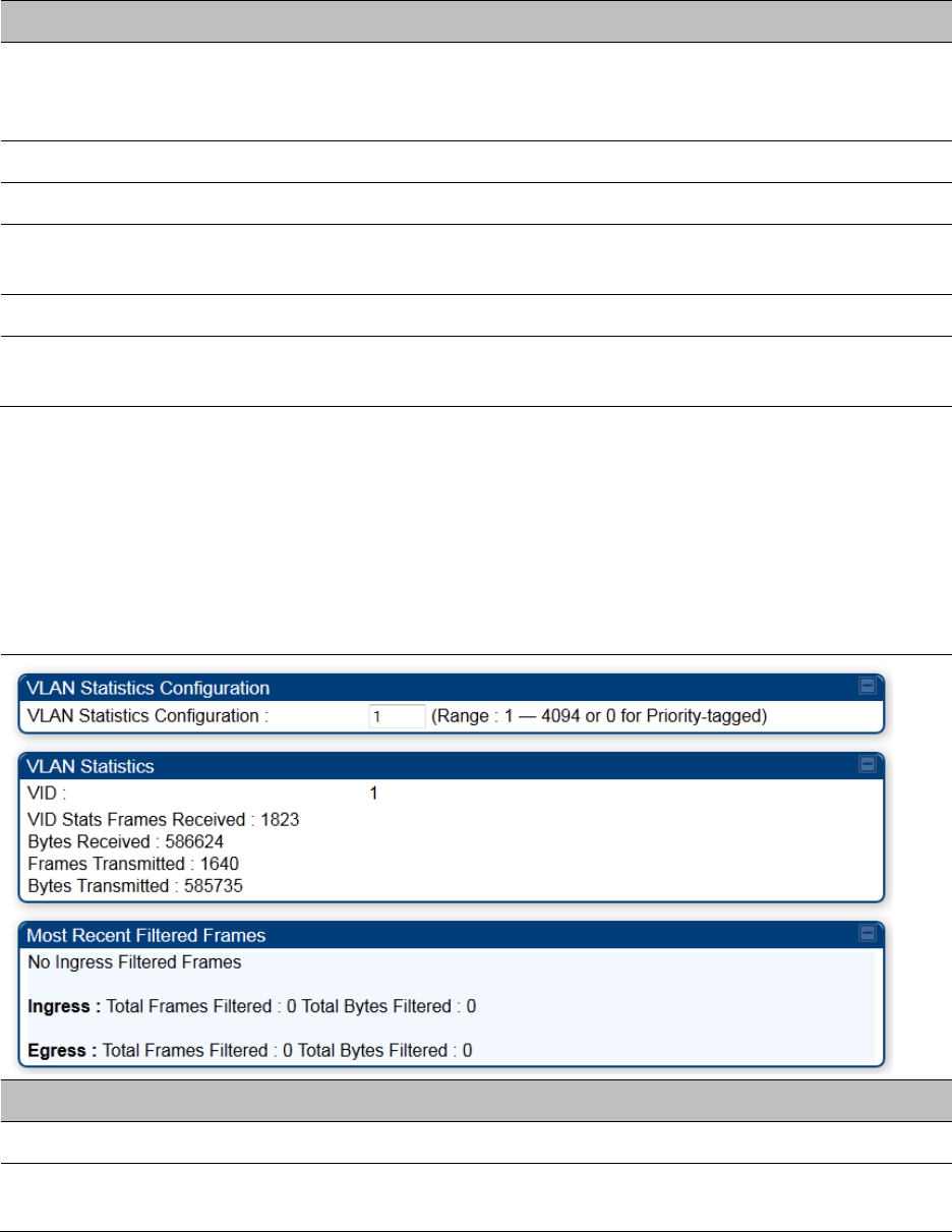
Chapter 9: Operation System statistics
Page 9-43
The following attributes are applicable only for 450m:
Attribute Meaning
mumimoVetoCount If excessive channel distortion is observed during condensed nulling
(tracking state) this count will increment and VC will transition back to
assessing state.
channelDistortion Channel distortion readings.
nullingSNR Signal to noise ratio of condensed nulling error response.
cnResponseCountS
M
The SM adds a counter to the CN response. This indicates how many
responses were sent by that SM.
cnResponseCountAP The AP increments a count for each CN response received.
missedTagCount This is the number of CN responses transmitted by SM but not received
at AP.
Interpreting VLAN statistics
The Statistics > VLAN page provides a list of the most recent packets that were filtered because of
VLAN membership violations. It is applicable for all modules (AP/SM/BHM/BHS).
Table 213 VLAN page attributes
Attribute Meaning
Unknown This must not occur. Contact Technical Support.
Only Tagged The packet was filtered because the configuration is set to accept only
packets that have an 802.1Q header and this packet did not.

Chapter 9: Operation System statistics
Page 9-44
Ingress When the packet entered through the wired Ethernet interface,
the packet was filtered because it indicated an incorrect VLAN
membership.
Local Ingress When the packet was received from the local TCP/IP stack, the packet
was filtered because it indicated an incorrect VLAN membership.
This must not occur. Contact Technical Support.
Egress When the packet attempted to leave through the wired Ethernet
interface, the packet was filtered because it indicated an incorrect VLAN
membership.
Local Egress When the packet attempted to reach the local TCP/IP stack, the packet
was filtered because it indicated an incorrect VLAN membership.
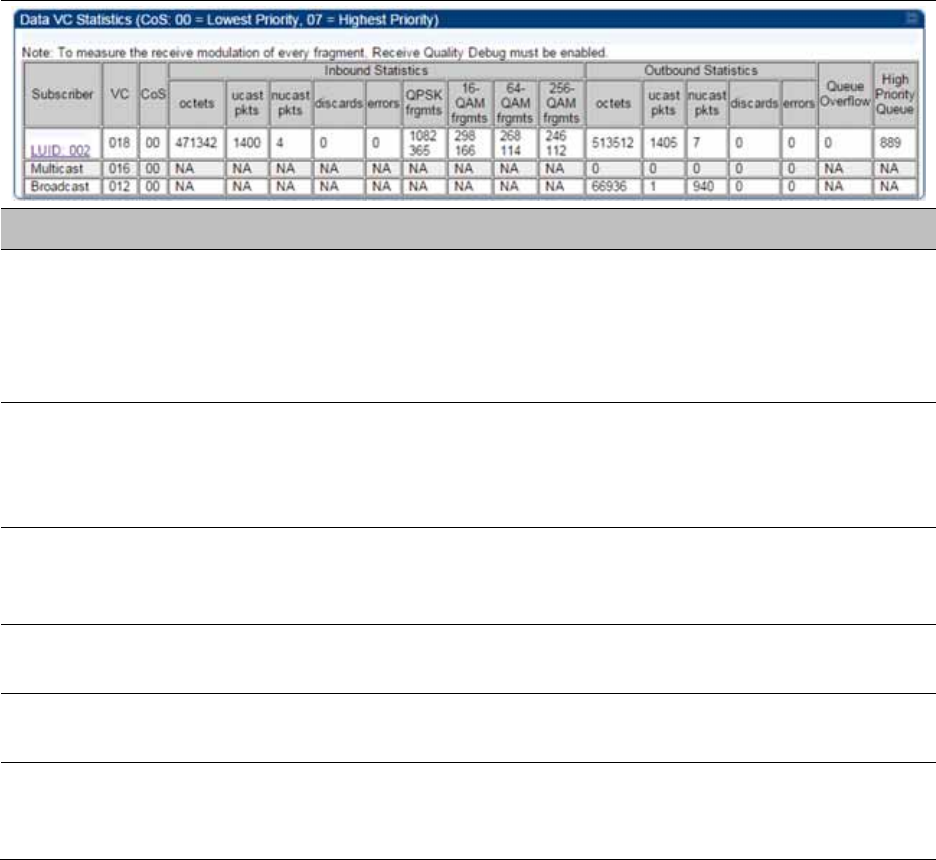
Chapter 9: Operation System statistics
Page 9-45
Interpreting Data VC statistics
The Statistics > Data VC page displays information about Virtual Channel (VC) used in data
communications. This page is applicable for all modules (AP/SM/BHM/BHS).
The Data VC tab displays the fields as explained in Table 214.
Table 214 Data VC page attributes
Attribute Meaning
Subscriber This field displays the LUID (logical unit ID), MAC address and Site Name
of the SM/BHS. As each SM or BHS registers to the AP/BHM, the system
assigns an LUID of 2 or a higher unique number to the SM/BHS. If a
SM/BHS loses registration with the AP/BHM and then regains
registration, the SM/BHS retains the same LUID.
VC This field displays the virtual channel number. Low priority channels
start at VC18 and count up. High priority channels start at VC255 and
count down. If one VC is displayed, the high-priority channel is disabled.
If two are displayed, the high-priority channel is enabled.
CoS This field displays the Class of Service for the virtual channel. The low
priority channel is a CoS of 00 and the high priority channel is a CoS of
01. CoS of 02 through 07 are not currently used.
Inbound Statistics,
octets
This field displays how many octets were received on the interface,
including those that deliver framing information.
Inbound Statistics,
ucastpkts
This field displays how many inbound subnetwork-unicast packets were
delivered to a higher-layer protocol.
Inbound Statistics,
nucastpkts
This field displays how many inbound non-unicast (subnetwork-
broadcast or subnetwork-multicast) packets were delivered to a higher-
layer protocol.

Chapter 9: Operation System statistics
Page 9-46
Inbound Statistics,
discards
This field displays how many inbound packets were discarded without
errors that would have prevented their delivery to a higher-layer
protocol. Inbound discard statistics are incremented similar to the
indiscards stat on the RF control block stats page. The sum of all data VC
indiscards must be close to the RF control block in discards. If indiscards
are evenly distributed across SMs, then the radio is PPS limited due to
either excessive small packet transmissions, or a problem at the Ethernet
link. If indiscards are contained to one or a few SMs, then there is likely a
problem at or underneath the SM which is incrementing the count.
Inbound Statistics,
errors
This field displays how many inbound packets contained errors that
prevented their delivery to a higher-layer protocol.
Inbound Statistics,
QPSK frgmts
This field displays how many inbound fragments were received via the
QPSK modulation scheme.
Inbound Statistics,
16-QAM frgmts
This field displays how many inbound fragments were received via the
16-QAM modulation scheme.
Inbound Statistics,
64-QAM frgmts
This field displays how many inbound fragments were received via the
64-QAM modulation scheme.
Inbound Statistics,
256-QAM frgmts
This field displays how many inbound fragments were received via the
256-QAM modulation scheme.
Outbound Statistics,
octets
This field displays how many octets were transmitted out of the
interface, including those that deliver framing information.
Outbound Statistics,
ucastpkts
This field displays how many packets for which the higher-level
protocols requested transmission to a subnetwork-unicast address. The
number includes those that were discarded or not sent.
Outbound Statistics,
nucastpkts
This field displays how many packets for which the higher-level
protocols requested transmission to a non-unicast (subnetwork-
broadcast or subnetwork-multicast) address. The number includes those
that were discarded or not sent.
Outbound Statistics,
discards
This field displays how many outbound packets were discarded without
errors that would have prevented their transmission. Outbound discard
statistics are incremented if a VC is not active when a packet is ready to
send. This is a rare condition.
Outbound Statistics,
errors
This field displays how many outbound packets contained errors that
prevented their transmission.
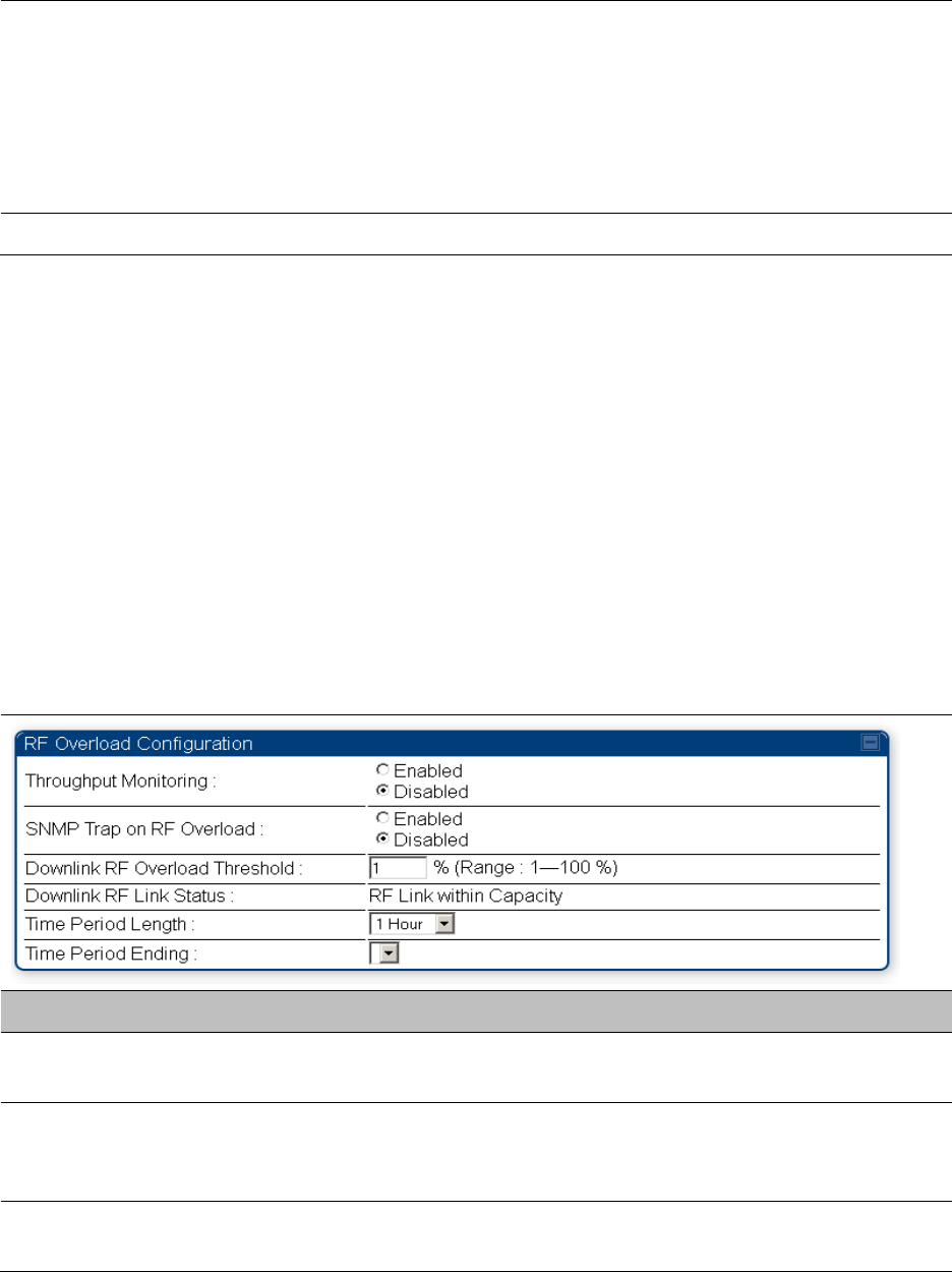
Chapter 9: Operation System statistics
Page 9-47
Queue Overflow This is a count of packets that were discarded because the queue for the
VC was already full. If Queue Overflows are being seen across most or
all SMs, then there is either an interferer local to the AP or the APs RF
link is at capacity. If Queue Overflows are being seen at one or only a
few SMs, then it is likely that there is a problem with those specific links
whether it is insufficient signal strength, interferer, or a problem with the
actual SM hardware.
High Priority Queue This is a count of packets that were received on high priority queue.
Interpreting Throughput statistics
The 450 Platform Family has a Statistics > Throughput page which shows historical information
about sector or backhaul throughput and packet discards. This page is applicable for AP and BHM
modules. This information can be useful to identify an overloaded sector or heavy bandwidth
users. This page also shows the user throughput in terms of data rate (kbps) and packet rate
(packets per second, or PPS), as well as the average packet size during the sample period.
Operators may set the AP/BHM to send an SNMP trap when it detects an RF overload condition
based on a configurable threshold.
The following configuration parameters are available on the Throughput tab GUI pane and a radio
reboot is not required when configuring these parameters:
Table 215 RF overload Configuration attributes – AP/BHM
Attribute Meaning
Throughput
Monitoring
This enables or disables the monitoring of sector throughput and packet
discards. This parameter is disabled by default.
SNMP Trap on RF
Overload
This enables or disables the sending of an SNMP trap when an AP/BHM
overload condition is reached (based on Downlink RF Overload
Threshold).
Downlink RF
Overload Threshold
This parameter determines the overload threshold in percent of packets
discarded that triggers the generation of an SNMP trap.

Chapter 9: Operation System statistics
Page 9-48
Downlink RF Link
Status
This field displays the status of the capacity of the RF link.
Time Period Length
Time Period Ending
These two configuration parameters determine what set of collection
samples to show on the GUI display. The Time Period Length can be set
from one to three hours. Time Period Ending allows the operator to set
the end time for the set of collection samples to display.
Below the configuration settings are three tables that display the statistics that are collected.
Board Performance statistics
This table contains a row that corresponds to each 1 minute statistics collection interval. Each row
contains the following data aggregated for the entire AP/BHM:
Ethernet Throughput - Statistics collected at the Ethernet port:
o kbps in – average throughput over the collection interval in Kbps into the AP/BHM on the
Ethernet Interface
o kbps out – average throughput over the collection interval in Kbps out of the AP/BHM on
the Ethernet Interface
o PPS in – average packets per second over the collection interval into the AP/BHM on the
Ethernet Interface
o PPS out – average packets per second over the collection interval out of the AP/BHM on the
Ethernet Interface
RF Throughput - Statistics collected at the RF Interface:
o kbps in – average throughput over the collection interval in Kbps into the AP/BHM on the
RF Interface
o kbps out – average throughput over the collection interval in Kbps out of the AP/BHM on
the RF Interface
o PPS in – average packets per second over the collection interval into the AP/BHM on the RF
Interface
o PPS out – average packets per second over the collection interval out of the AP/BHM on the
RF Interface
Aggregate Through Board – Sum of bidirectional data transferred through (not originating or
terminating at) the AP/BHM:
o kbps – average bidirectional throughput over the collection interval in Kbps
o PPS – average bidirectional packets per second over the collection interval
o Ave Pkt Size – Average Packet size over the collection interval of bidirectional data
transferred
Board Throughput statistics
This table contains a row that corresponds to each one minute statistics collection interval. This
table may be used to determine if there are problems with any of the interfaces. For example, if the
Ethernet in packets is much higher than the RF out packets it could indicate a denial of service
(DoS) attack on the AP/BHM. Each row contains the following data aggregated for the entire
AP/BHM:
Chapter 9: Operation System statistics
Page 9-49
Ethernet Statistics - Statistics collected at the Ethernet port:
o inOctets – Number of octets (bytes) received by the AP/BHM at the Ethernet Interface over
the collection interval
o outOctets – Number of octets (bytes) sent by the AP/BHM at the Ethernet Interface over the
collection interval
o inPkts – Number of packets received by the AP/BHM at the Ethernet Interface over the
collection interval
o outPkts – Number of packets sent by the AP/BHM at the Ethernet Interface over the
collection interval
o Discards (in/out) – Number of packets that had to be discarded by the AP/BHM at the
respective Ethernet Interface Queue
RF Statistics - Statistics collected at the RF Interface:
o inOctets – Number of octets (bytes) received by the AP/BHM at the RF Interface over the
collection interval
o outOctets – Number of octets (bytes) sent by the AP/BHM at the RF Interface over the
collection interval
o inPkts – Number of packets received by the AP/BHM at the RF Interface over the collection
interval
o outPkts – Number of packets sent by the AP/BHM at the RF Interface over the collection
interval
o Discards (in/out) – Number of packets that had to be discarded by the AP/BHM at the
respective RF Interface Queue during the collection interval
o Discards % (in/out) – Percent of the total packets received / transmitted that had to be
discarded during the collection interval
LUID RF Throughput statistics
This table contains a row that corresponds to each active LUID served by the AP/BHM. Note that an
LUID may be assigned 1 or 2 VCs. If the LUID is assigned 2 VCs, then the data in the table is the
sum of the activity for both VCs. This table may be used to determine which LUIDs are
experiencing overload so that corrective action can be taken (i.e. fixing a poor RF link or moving a
heavily loaded link to a less congested AP/BHM). Each row contains counters and statistics related
to the RF Interface that are updated once per minute:
Inbound Statistics - Statistics collected at the RF Interface for the Uplink:
o octets – Number of octets (bytes) received by the AP/BHM at the RF Interface for this LUID
over the collection interval
o pkts – Number of packets received by the AP/BHM at the RF Interface for this LUID over the
collection interval
o Ave Pkt Size – Average size of the packets received by the AP/BHM at the RF Interface for
this LUID over the collection interval
o discards – Number of packets received by the AP/BHM at the RF Interface for this LUID over
the collection interval that had to be discarded because the RF In Queue was full
o discards % – Percent of the total packets received by the AP/BHM at the RF Interface for this
LUID over the collection interval that had to be discarded because the RF In Queue was full
Outbound Statistics - Statistics collected at the RF Interface for the Downlink:
o octets – Number of octets (bytes) transmitted by the AP/BHM at the RF Interface for this
LUID over the collection interval
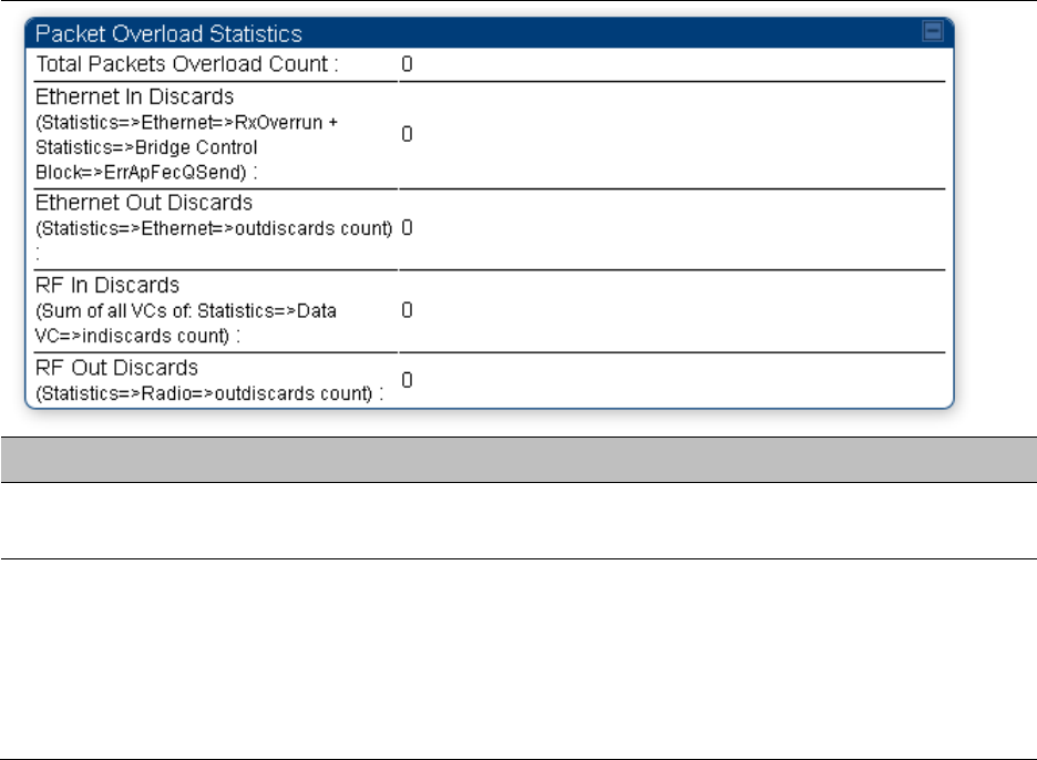
Chapter 9: Operation System statistics
Page 9-50
o pkts – Number of packets transmitted by the AP/BHM at the RF Interface for this LUID over
the collection interval
o Ave Pkt Size – Average size of the packets transmitted by the AP/BHM at the RF Interface
for this LUID over the collection interval
o discards – Number of packets to be transmitted by the AP/BHM at the RF Interface for this
LUID over the collection interval that had to be discarded because the RF Out Queue was
full
o discards % – Percent of the total packets to be transmitted by the AP/BHM at the RF
Interface for this LUID over the collection interval that had to be discarded because the RF
Out Queue was full.
Interpreting Overload statistics
The Statistics > Overload page displays statistics on packet overload and resultant packet discards.
Unlike the other fields, the Total Packets Overload Count is expressed in only this page. It is not a
count of how many packets have been lost, but rather of how many discard events (packet loss
bursts) have been detected due to overload condition.
This statistics page is applicable for all modules (AP/SM/BHM/BHS) and explained in Table 216.
Table 216 Overload page attributes – AP/SM/BHM/BHS
Attribute Meaning
Total Packets
Overload Count
This field represents the sum of all RF and Ethernet in/out discards.
Ethernet In Discards This field represents the number of packets tossed due to the Ethernet
queue being full. If a climb in this stat accompanies a climb in RF Out
Discards stat, then most likely the board is at RF capacity either due to
traffic exceeding the RF pipe, or interference temporarily limiting the RF
throughput. If this stat climbs without the RF Out Discards stat climbing,
then the radio is most likely PPS limited.

Chapter 9: Operation System statistics
Page 9-51
Ethernet Out
Discards
This field represents the number of packets tossed due to an Ethernet
out overload. This stat must not climb in normal operation because the
Ethernet link is much higher capacity than the RF link. If this stat is
incrementing, then either the Ethernet link is established at a low speed
(i.e. 10Mbps – half duplex), or there is a problem with cabling/Ethernet
hardware.
RF In Discards This field indicates the number of packets tossed due to no resources
available within the radio to process them. This stat also must not be
increasing because the system is designed to shed packets on the RF
Out interface. If this stat is incrementing the board, it is most likely
congested due to high PPS rate in combination with an Ethernet Out
problem, which limits packet flow off the device.
RF Out Discards This field indicates the number of packets tossed due to RF link at
capacity. This stat will increase whenever the RF link is at capacity. When
the internal FPGA RF input queue overflows, this stat is incremented. If
this stat is seen to be incrementing at the AP, then the sector is
congested. If seen at the SM, the number of Contention Slots must be
looked at to ensure that enough Contention Slots are allocated to allow
for bandwidth requests to be seen at the AP.

Chapter 9: Operation System statistics
Page 9-52
Note
450m Overload:
The 450m Series AP is designed to handle high load in terms of high throughput and
high PPS. In terms of throughput, 450m is designed to achieve 3x or more throughput
improvement over 450 and 450i Series products. In terms of packets per second (PPS),
450m is designed to handle up to 100k PPS.
Overload occurs when the offered load exceeds the above limits. When overload
occurs, 450m will start discarding packets and TCP throughput will degrade due to
packet loss.
It’s worth noting that Frame Utilization statistics (Statistics > Frame Utilization tab:
Frame Utilization: Downlink and Uplink) are not necessarily indicative of overload
condition. They show how much the TDD frame is utilized. High frame utilization
depends on:
High traffic during busy periods: those statistics will be close to 100% and almost
all slots will be utilized. In this case if the Overload statistics show that packets are
discarded then this is an indication of overload condition.
High percentage of VCs with low modulation with moderate traffic. Those VCs will
require more slots to service them (due to low modulation) and the frame
utilization will be high. In this case the TDD frame is fully utilized but the system is
at low capacity and is not in an overload condition.
450m has higher PPS than 450 and 450i and supports higher throughput through
spatial multiplexing, therefore when a 450m replaces an overloaded 450 or 450i AP the
450m will not be overloaded under the same conditions but the frame utilization may
still show close to 100%; this should not alarm the customer. The overload statistics
shall be monitored on 450m to see if it is overloaded or not.
Interpreting DHCP Relay statistics
The Statistics > DHCP Relay page displays requests and replies received, relayed and discarded
when the AP is configured as a DHCP relay. Typically, in a working DHCP relay configuration a
one-to-one ratio is established between requests and replies that are received and relayed. This
statistics page is only applicable for PMP (AP and SM modules) and it is explained in Table 217.
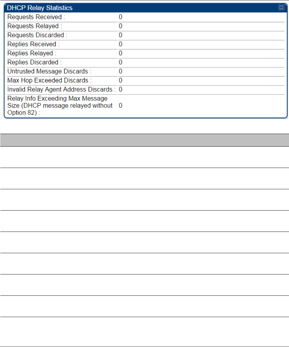
Chapter 9: Operation System statistics
Page 9-53
Table 217 DHCP Relay page attributes – AP/SM
Attribute Meaning
Requests Received This field represents the number of DHCP relay requests received by the
AP.
Requests Relayed This field represents the number of DHCP relay requests relayed by the
AP.
Requests Discarded This field represents the number of DHCP relay requests discarded by
the AP due to errors in the request.
Replies Received This field represents the number of DHCP relay replies received by the
AP.
Replies Relayed This field represents the number of DHCP relay replies relayed by the
AP.
Replies Discarded This field represents the number of DHCP relay replies discarded by the
AP due to errors in the reply.
Untrusted Message
Discards
This field indicates messages that were discarded because the message
already contained Option 82 information with no Relay Agent specified.
Max Hop Exceeded
Discards
This field indicates messages that have been relayed too many times,
exceeding the max hop count (16).
Invalid Relay Agent
Address Discards
This field indicates messages that have been discarded because the
message relay agent address is already in place (relay agent address
does not equal address of the AP).
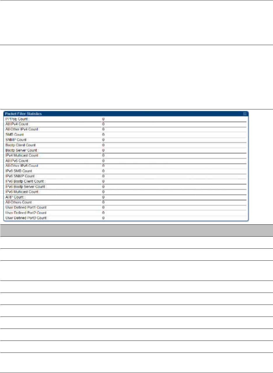
Chapter 9: Operation System statistics
Page 9-54
Relay Info Exceeding
Max Message Size
(DHCP message
relayed without
Option 82)
This field indicates DHCP messages too large to fit Option 82 data. These
messages are sent on without Option 82 information.
Interpreting Filter statistics
The Statistics > Filter page displays statistics on packets that have been filtered (dropped) due to
the filters set on the Protocol Filtering page. The filter page of SM is explained in Table 218.
Table 218 Filter page attributes - SM
Attribute Meaning
PPPoE Count Number of PPPoE packets filtered.
All IPv4 Count Number of IPv4 packets filtered.
All Other IPv4 Count Any IPv4 message that was not SMB, SNMP, Bootp, Multicast or
one of the user defined filters, that was filtered out.
SMB Count Number of IPv4 Server Message Block (file sharing) packets filtered.
SNMP Count Number of IPv4 SNMP packets filtered.
Bootp Client Count Total number of IPv4 DHCP requests filtered.
Bootp Server Count Total number of IPv4 DHCP replies filtered.
IPv4 Multicast Count Number of IPv4 Multicast messages filtered.
All IPv6 Count Number of IPv6 messages filtered.
All Other IPv6 Count Any IPv6 message that was not SMB, SNMP, Bootp, Multicast or
one of the user defined filters, that was filtered out.
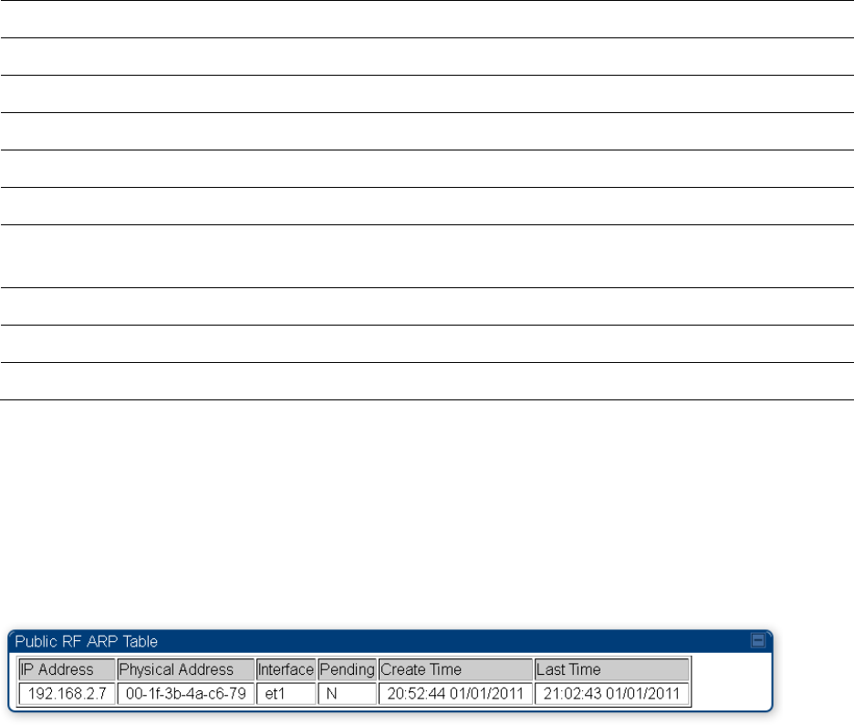
Chapter 9: Operation System statistics
Page 9-55
IPv6 SMB Count Number of IPv6 Server Message Block (file sharing) packets filtered
IPv6 SNMP Count Number of IPv6 SNMP messages filtered
IPv6 Bootp Client Count Total number of IPv6 DHCP replies filtered
IPv6 Bootp Server Count Total number of IPv6 DHCP replies filtered
IPv6 Multicast Count Number of IPv6 Multicast messages filtered
ARP Count Total number of ARP packets filtered.
All other Count The count of any messages that did not fit above that were filtered
out
User Defined Port1 Count Number of packets defined by the user port1 that were filtered.
User Defined Port2 Count Number of packets defined by the user port2 that were filtered.
User Defined Port3 Count Number of packets defined by the user port3 that were filtered.
Viewing ARP statistics
The Statistics > ARP page in a SM module correlated the IP address of the Ethernet-connected
device to its MAC address and provides data about the connection.
Figure 185 ARP page of the SM
Viewing NAT statistics
When NAT is enabled on a SM, statistics are kept on the Public and Private (WAN and LAN) sides
of the NAT and displayed on the Statistics > NAT Stats page. The NAT page of SM is explained in
Table 219.
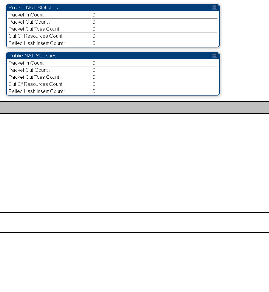
Chapter 9: Operation System statistics
Page 9-56
Table 219 NAT page attributes - SM
Attribute Meaning
Private NAT Statistics,
Packet In Count
This field represents the number of packets received on the SM’s
LAN/Ethernet interface
Private NAT Statistics,
Packet Out Count
This field represents the number of packets sent from the SM’s
LAN/Ethernet interface
Private NAT Statistics,
Packet Out Toss Count
This field represents the number of packets that we not sent from the
SM’s LAN/Ethernet interface due to addressing issues.
Private NAT Statistics,
Out of Resources Count
This field represents the number of times the NAT table for the SM’s
LAN/Ethernet interfaces has been filled.
Private NAT Statistics,
Failed Hash Insert Count
This field represents the number of times that the device failed to
insert an address binding into the NAT hash table.
Public NAT Statistics,
Packet In Count
This field represents the number of packets received on the SM’s
WAN/wireless interface
Public NAT Statistics,
Packet Out Count
This field represents the number of packets sent from the SM’s
WAN/wireless interface
Public NAT Statistics,
Out of Resources Count
This field represents the number of packets that we not sent from the
SM’s WAN/wireless interface due to addressing issues.
Public NAT Statistics,
Failed Hash Insert Count
This field represents the number of times the NAT table for the SM’s
WAN/wireless interfaces has been filled.
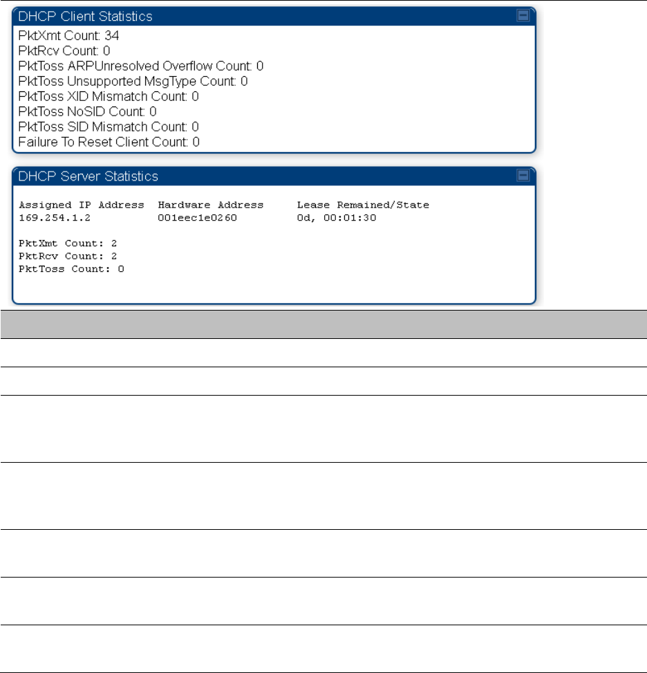
Chapter 9: Operation System statistics
Page 9-57
Viewing NAT DHCP Statistics
The Statistics > NAT DHCP page displays NAT enabled DHCP client statistics. This is statistics page
is applicable for SM only.
When NAT is enabled on a SM with DHCP client (DHCP selected as the Connection Type of the
WAN interface) and/or DHCP Server, statistics are kept for packets transmitted, received and
tossed, as well as a table of lease information for the DHCP server (Assigned IP Address, Hardware
Address and Lease Remained/State).
Table 220 NAT DHCP Statistics page attributes - SM
Attribute Meaning
PktXmt Count Represents the number of DHCP packets transmitted from the client
PktRcv Count This field represents the number of DHCP packets received by the client
PktToss
ARPUnresolved
Overflow Count
This field represents the number of packets tossed due to failed attempts
to resolve an IP address into a physical MAC address
PktToss
Unsupported
MsgType Count
This field represents the number of packets tossed due to the receipt of
an unsupported message type (cannot be interpreted by DHCP client)
PktToss XID
Mismatch Count
The field represents the number of packets that were tossed due to a
transaction ID mismatch
PktToss NoSID
Count
This field represents the number of packets that were tossed due to lack
of a DHCP session ID
PktToss SID
Mismatch Count
Represents the number of packets tossed due to a session ID mismatch
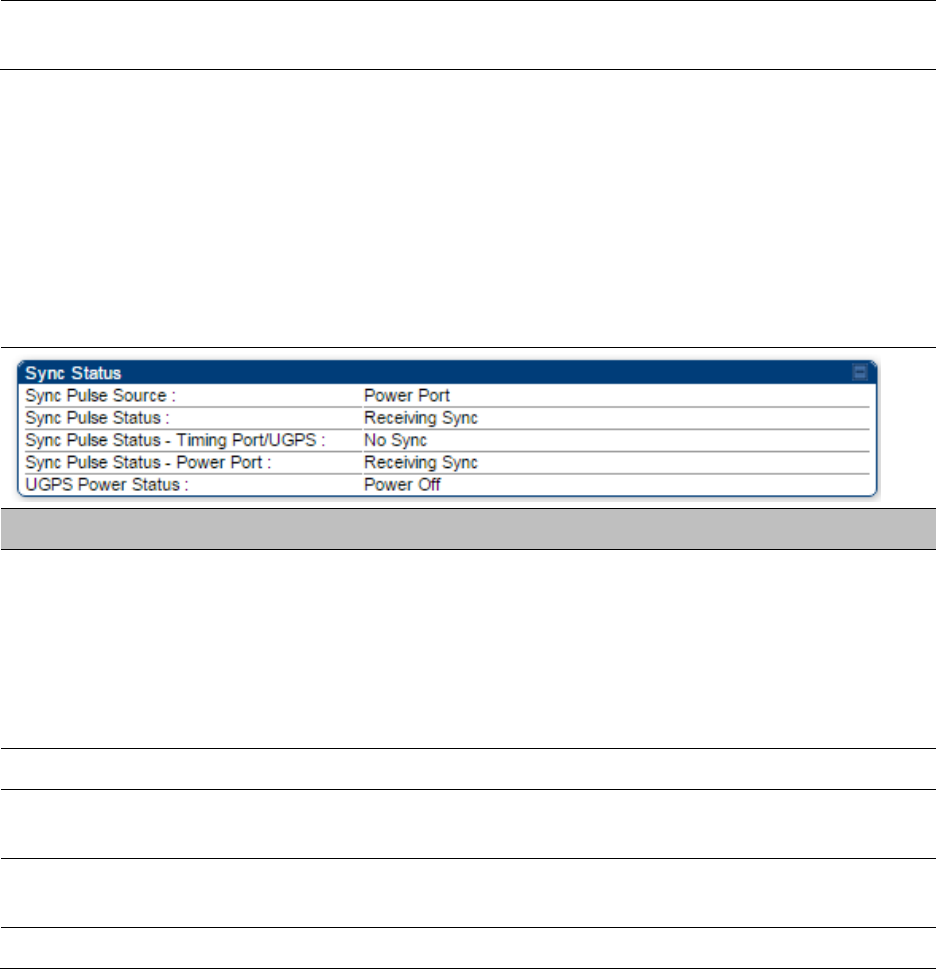
Chapter 9: Operation System statistics
Page 9-58
Failure to Reset
Client Count
This field represents the number of times the DHCP client was unable to
be reset (resulting in no IP address being served).
Interpreting Sync Status statistics
The Statistics > Sync Status page of AP is only displayed when the Sync Input is set to AutoSync
or AutoSync+Free Run.
The Sync Status page is explained in Table 221.
Table 221 Sync Status page attributes - AP
Attribute Meaning
Sync Pulse Source This field indicates the status of the synchronization source:
Searching indicates that the unit is searching for a GPS fix
Timing Port/UGPS indicates that the module is receiving sync via the
timing AUX/SYNC timing port
Power Port indicates that the module is receiving sync via the power
port (Ethernet port).
Sync Pulse Status This field indicates synchronization source pulse status.
Sync Pulse Status –
Timing Port/UGPS
This field indicates synchronization pulse status over Timing Port/UGPS
port.
Sync Pulse Status -
Power Port
This field indicates synchronization pulse status over power port.
UGPS Power Status This field indicates UGPS power up status (on or off).
This information may be helpful in a decision of whether to climb a tower to diagnose a perceived
antenna problem.
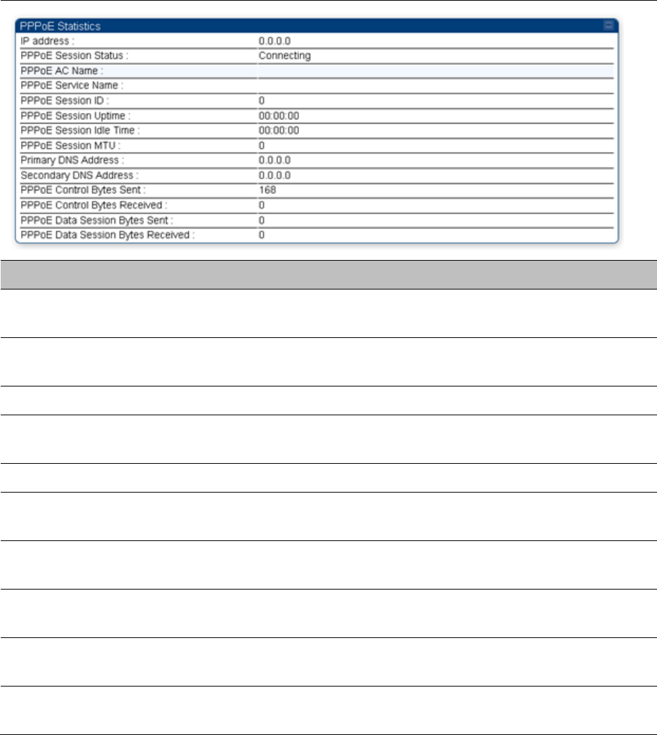
Chapter 9: Operation System statistics
Page 9-59
Interpreting PPPoE Statistics for Customer Activities
The page can be access under Statistics > PPPoE of SM GUI.
When the PPPoE feature is enabled on the SM, PPPoE statistics provide data about activities of the
customer.
The PPPoE Statistics of SM is explained in Table 222.
Table 222 PPPoE Statistics page attributes - SM
Attribute Meaning
IP address This field displays the IP address of the PPPoE session initiator (situated
below the SM)
PPPoE Session
Status
This field displays the operational status of the PPPoE Session
PPPoE AC Name This field displays access concentrator name used in the PPPoE session
PPPoE Service Name This field displays the PPPoE service name associated with the PPPoE
server in use
PPPoE Session ID This field displays the current PPPoE session ID
PPPoE Session
Uptime
This field displays the total session uptime for the PPPoE session
PPPoE Session Idle
Time
This field displays the total idle time for the PPPoE session
PPPoE Session MTU This field displays Maximum Transmission Unit configured for the
PPPoE session
Primary DNS
Address
This field displays the primary DNS server used by the PPPoE session
Secondary DNS
Address
This field displays the secondary DNS server used by the PPPoE session

Chapter 9: Operation System statistics
Page 9-60
PPPoE Control Bytes
Sent
Displays the total number of PPPoE session control bytes sent from SM
PPPoE Control Bytes
Received
This field displays the total number of PPPoE session control bytes
received by the SM
PPPoE Data Session
Bytes Sent
This field displays the total number of PPPoE data session (non-
control/non-session management user data) sent by the SM
PPPoE Data Session
Bytes Received
This field displays the total number of PPPoE data session (non-
control/non-session management user data)
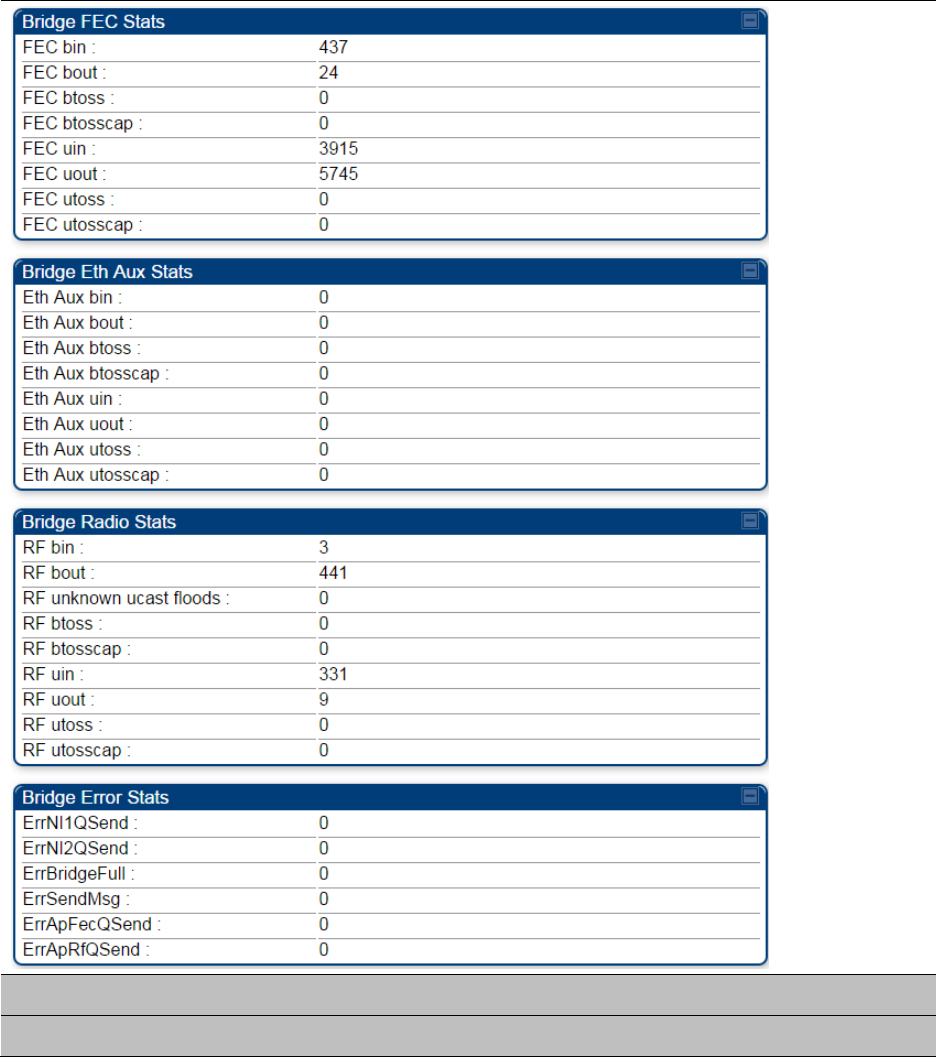
Chapter 9: Operation System statistics
Page 9-61
Interpreting Bridge Control Block statistics
The Statistics > Bridge Control Block page displays statistics of Bridge FEC, Bridge ratio and Bridge
error. The page is applicable for all modules (AP/SM/BHM/BHS). The Bridge Control Block
Statistics page is explained in Table 223.
Table 223 Bridge Control Block page attributes – AP/SM/BHM/BHS
Attribute Meaning
Bridge FEC Stats

Chapter 9: Operation System statistics
Page 9-62
FEC bin This field indicates the number of broadcast packets received by the
bridge control block on the Main Ethernet interface
FEC bout This field indicates the number of broadcast packets sent by the bridge
control block on the Main Ethernet interface
FEC btoss This field indicates the number of broadcast packets tossed out by the
bridge control block on the Main Ethernet interface
FEC btosscap This field indicates the number of broadcast packets tossed out at the
Main Ethernet interface due to MIR cap being exceeded.
FEC uin This field indicates the number of unicast packets received by the bridge
control block on the Main Ethernet interface
FEC uout This field indicates the number of unicast packets sent by the bridge
control block on the Main Ethernet interface
FEC utoss This field indicates the number of unicast packets tossed by the bridge
control block on the Main Ethernet interface
FEC utosscap This field indicates the number of unicast packets tossed out at the Main
Ethernet interface due to MIR cap being exceeded.
Bridge Eth Aux Stats
FEC bin This field indicates the number of broadcast packets received by the
bridge control block on the Aux Ethernet interface
FEC bout This field indicates the number of broadcast packets sent by the bridge
control block on the Aux Ethernet interface
FEC btoss This field indicates the number of broadcast packets tossed out by the
bridge control block on the Aux Ethernet interface
FEC btosscap This field indicates the number of broadcast packets tossed out at the
Aux Ethernet interface due to MIR cap being exceeded.
FEC uin This field indicates the number of unicast packets received by the bridge
control block on the Aux Ethernet interface
FEC uout This field indicates the number of unicast packets sent by the bridge
control block on the Aux Ethernet interface
FEC utoss This field indicates the number of unicast packets tossed by the bridge
control block on the Aux Ethernet interface
FEC utosscap This field indicates the number of unicast packets tossed out at the Aux
Ethernet interface due to MIR cap being exceeded.
Bridge Radio Stats
RF bin This field indicates the number of broadcast packets received by the
bridge control block on the radio interface

Chapter 9: Operation System statistics
Page 9-63
RF bout This field indicates the number of broadcast packets sent by the bridge
control block on the radio interface
RF btoss This field indicates the number of broadcast packets tossed by the
bridge control block on the radio interface
RF btosscap This field indicates the number of broadcast packets tossed out at the
radio interface due to MIR cap being exceeded.
RF uin This field indicates the number of unicast packets received by the bridge
control block on the radio interface
RF uout This field indicates the number of unicast packets sent by the bridge
control block on the radio interface
RF utoss This field indicates the number of unicast packets tossed by the bridge
control block on the radio interface
RF utosscap This field indicates the number of unicast packets tossed out at the radio
interface due to MIR cap being exceeded.
Bridge Error Stats
ErrNI1QSend This field indicates that a packet which was sourced from the radio
network stack interface 1 (Ethernet interface) could not be sent because
the radio bridge queue was full. The packet was tossed out.
ErrNI2QSend This field indicates that a packet which was sourced from the radio
network stack interface 2 (RF interface) could not be sent because the
radio bridge queue was full. The packet was tossed out.
ErrBridgeFull This field indicates the total number of times the bridging table was full
and could not accept new entries.
ErrSendMsg This field displays the error message from bridge core call back routine.
ErrApFecQSend This field indicates that a packet which was received on the Ethernet
interface could not be processed because the radio bridge queue was
full and packet was tossed out.
ErrApRfQSend This field indicates that a packet which was received on the RF interface
could not be processed because the radio bridge queue was full. The
packet was tossed out.
Note:
PMP 450m Series AP does not support Aux port in current release of 15.0/15.0.0.1.
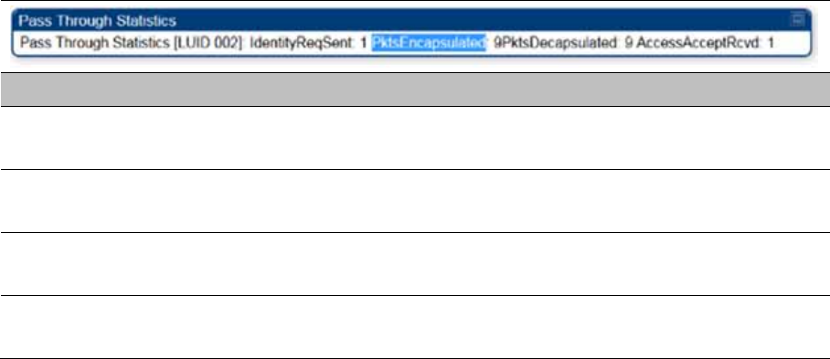
Chapter 9: Operation System statistics
Page 9-64
Interpreting Pass Through Statistics
The Statistics > Pass Through Statistics page displays radius related statistics. The page is
applicable for PMP 450 Platform Family - AP only. The Pass Through Statistics page is explained in
Table 224.
Table 224 Pass Through Statistics page attributes – AP
Attribute Meaning
IdentityReqSent This field indicates the number of EAP Identity requests sent
through the AP with respect to an SM.
PktsEncapsulated This field indicates no of packets received from the SM which are
encapsulated by the AP.
PktsDecasulated This field indicates no of packets received from the radius server
and are decapsulated by the AP with respect to an SM
AccessAcceptRcvd This field indicates no of RADIUS Access Accept message
received by the AP with respect to an SM.
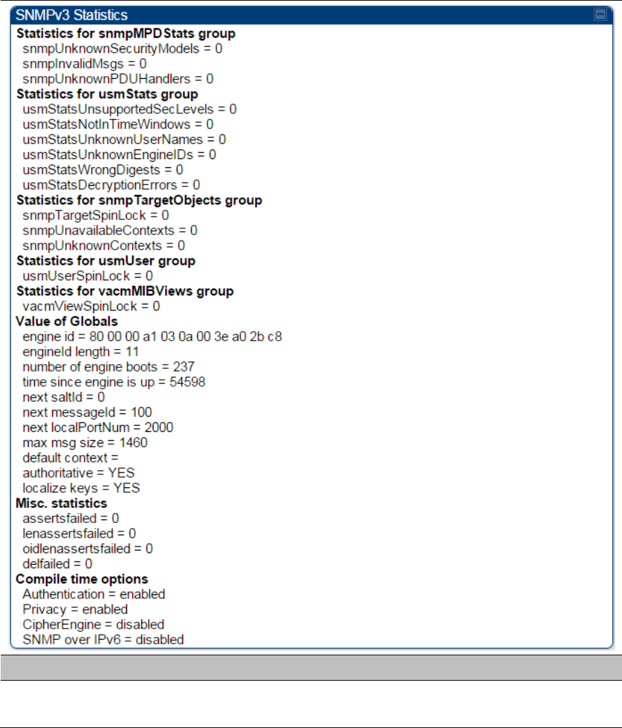
Chapter 9: Operation System statistics
Page 9-65
Interpreting SNMPv3 Statistics
The Statistics > SNMPv3 Statistics page displays all SNMPv3 related statistics. The page is
applicable for all type of ODUs of PMP 450 Platform. The SNMPv3 Statistics page is explained in
Table 225.
Table 225 SNMPv3 Statistics page attributes – AP
Attribute Meaning
Statistics for
snmpMPDStats group SNMP Message Processing and Dispatching RFC 3412

Chapter 9: Operation System statistics
Page 9-66
snmpUnknownSecurityM
odels
The total number of packets received by the SNMP engine which
were dropped because they referenced a securityModel that was
not known to or supported by the SNMP engine.
snmpInvalidMsgs The total number of packets received by the SNMP engine which
were dropped because there were invalid or inconsistent
components in the SNMP message.
snmpUnknownPDUHandl
ers
The total number of packets received by the SNMP engine which
were dropped because the PDU contained in the packet could
not be passed to an application responsible for handling the
pduType, e.g. no SNMP application had registered for the proper
combination of the contextEngineID and the pduType.
usmStatsUnsupportedSec
Levels
The total number of packets received by the SNMP engine which
were dropped because they requested a securityLevel that was
unknown to the SNMP engine or otherwise unavailable.
usmStatsNotInTimeWind
ows
The total number of packets received by the SNMP engine which
were dropped because they appeared outside of the
authoritative SNMP engine's window.
usmStatsUnknownUserN
ames
The total number of packets received by the SNMP engine which
were dropped because they referenced a user that was not
known to the SNMP engine.
usmStatsUnknownEngine
IDs
The total number of packets received by the SNMP engine which
were dropped because they referenced a snmpEngineID that was
not known to the SNMP engine.
usmStatsWrongDigests The total number of packets received by the SNMP engine which
were dropped because they didn't contain the expected digest
value.
usmStatsDecryptionError
s
The total number of packets received by the SNMP engine which
were dropped because they could not be decrypted.
snmpTargetSpinLock This object is used to facilitate modification of table entries in the
SNMP-TARGET-MIB module by multiple managers.
snmpUnavailableContext
s
The total number of packets received by the SNMP engine which
were dropped because the context contained in the message
was unavailable.
snmpUnknownContexts The total number of packets received by the SNMP engine which
were dropped because the context contained in the message
was unknown.
usmUserSpinLock The use of usmUserSpinlock is to avoid conflicts with another
SNMP command generator application which may also be acting
on the usmUserTable.
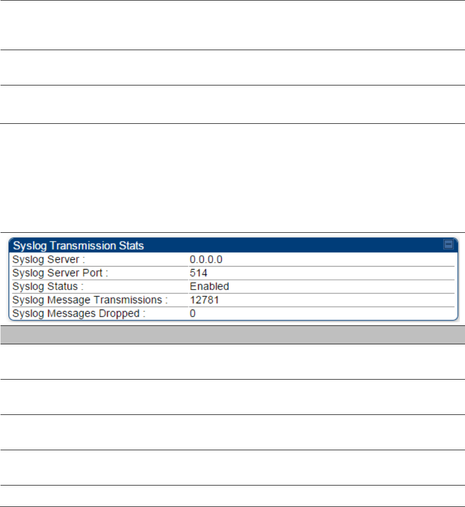
Chapter 9: Operation System statistics
Page 9-67
vacmViewSpinLock An advisory lock used to allow cooperating SNMP Command
Generator applications to coordinate their use of the Set
operation in creating or modifying views.
snmpEngineBoots It is a count of the number of times the SNMP engine has re-
booted/re-initialized since snmpEngineID was last configured
snmpEngineTime
time since engine is up
which is the number of seconds since the snmpEngineBoots
counter was last incremented
Interpreting syslog statistics
The Statistics > Syslog Statistics page displays statistics of syslog messages. The page is
applicable for all modules (AP/SM/BHM/BHS). The Syslog Statistics page is explained in Table 226.
Table 226 Syslog statistics page attributes – AP/SM/BH
Attribute Meaning
Syslog Server This displays dotted decimal or DNS name (if the DNS is
enabled) of the syslog server address.
Syslog Server Port The syslog server port (default 514) to which syslog messaging
is sent.
Syslog Status This indicates status of syslog messaging. It can be Enable or
Disabled based on configuration
Syslog Message
Transmissions
This field indicates the count of syslog messages sent to UDP
layer.
Syslog Message Dropped This field indicates the count of dropped syslog messages.
Interpreting Frame Utilization statistics
The Frame Utilization Statistics is a feature helps user to understand how effectively the RF
channel is being utilized. This feature allows to check Time Division Duplex (TDD) frame utilization
pattern and diagnose for any excessive usage in uplink or downlink direction.
This forms the first step of identifying the TDD frame utilization information. If the user finds
excessive utilization based on this stats, the second step would be to take several actions like
sectorization, tuning the uplink/downlink ratio etc. to improve RF channel utilization. Efficient use
of the TDD frame will help to achieve optimum performance of link.
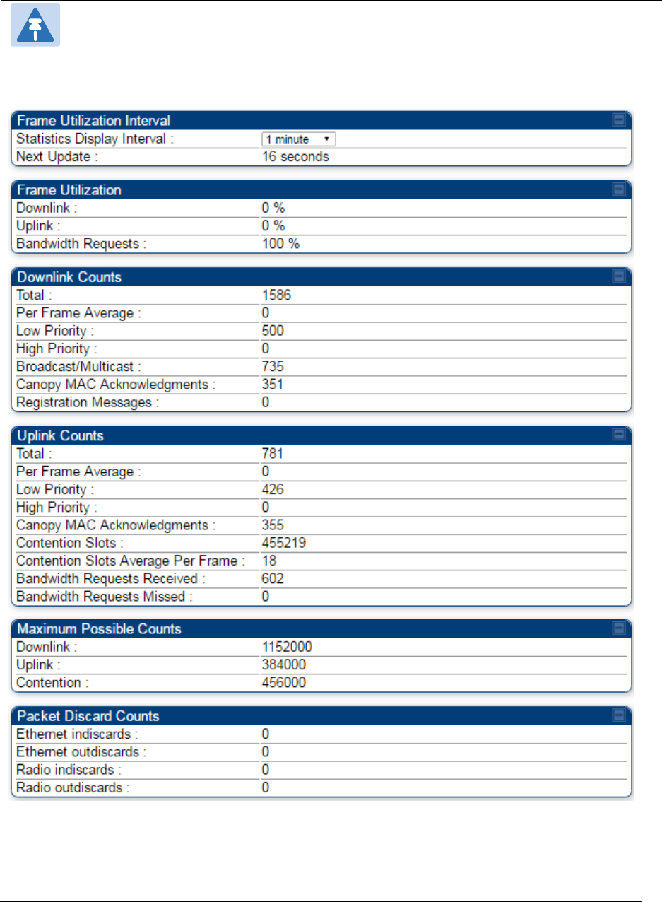
Chapter 9: Operation System statistics
Page 9-68
Note:
The backhauls (BHM and BHS) will have only the downlink scheduler based
statistics
Table 227 Frame utilization statistics

Chapter 9: Operation System statistics
Page 9-69
Attribute Meaning
Frame Utilization Interval
Statistics Display interval This allows to configure timer interval to monitor and display the
frame utilization statistics. It can be configured for 1 minutes
seconds (low interval), 5 minutes (medium interval) or 15
minutes (high interval) based on requirement.
Frame Utilization
Downlink This indicates the percentage of downlink data slots used against
the maximum number of slots possible in the configured
interval.
Uplink This indicates the percentage of uplink data slots used against
the maximum number of uplink slots possible in the configured
interval.
Bandwidth Requests The "Bandwidth Request" is a message sent from the SM to the
AP asking to be scheduled for bandwidth to send in the uplink.
This gets transmitted in the unscheduled portion of the uplink.
Unscheduled uplink is defined as Contention Slots +
unscheduled uplink slots. Since this is sent in the unscheduled
portion of the uplink, it will result in collisions when SMs
randomly pick the same slot.
The "Bandwidth Request Missed" metrics are to add data to
know how many of requests are colliding. If it is near 100%, then
near all of the SM’s bandwidth requests are getting through to
the AP, so this a is near perfect scenario. If it is significantly less
than that, you may be experiencing uplink latency as your SMs
are attempting to request bandwidth and are unable to do so.
Also note that if it is consistently at 100% the AP may be able to
reduce its contention slots to a lower value and gain more data
slots.
Downlink Counts
Total This indicates the sum of all downlink data slots used in the
configured interval.
Per Frame Average This indicates the average data per frame in the downlink traffic.
Low Priority The number of downlink data slots used for low priority
downlink traffic.
High Priority The number of downlink data slots used for high priority
downlink traffic.
Broadcast/Multicast The number of downlink data slots used for broadcast and
multicast traffic.

Chapter 9: Operation System statistics
Page 9-70
Canopy MAC
Acknowledgements
The number of downlink data slots used as ACKs.
Registration Messages The number of downlink data slots used for registration
messages.
Uplink Counts
Total This indicates the sum of all uplink data slots used in configured
interval.
Per Frame Average This indicates the average data per frame in the uplink traffic.
Low Priority The number of uplink data slots used for low priority uplink
traffic.
High Priority The number of uplink data slots used for high priority uplink
traffic.
Canopy MAC
Acknowledgements
The number of uplink data slots used as ACKs.
Contention Slots The number of (reserved contention slots + unscheduled
symbols that can be used as contention slots) Contention slots
configured by the operator.
Contention Slots Average
Per Frame
It is the average number of contention slots in a frame for the
last duration. Duration is 1/5/15 mins.
Bandwidth Requests
Received
This indicates the number of Bandwidth Requests received from
SMs.
Bandwidth Requests
Missed
This indicates how many of Bandwidth Requests are colliding.
Maximum possible counts
Downlink This indicates the maximum possible downlink data slots in the
configured interval. This is based on the configuration of
Channel Bandwidth, Frame period, uplink/downlink allocation,
contention slots and configured Statistics Display interval.
Uplink This indicates the maximum possible uplink data slots in the
configured interval. This is based on the configuration of
Channel Bandwidth, Frame period, uplink/downlink allocation,
contention slots and configured Statistics Display interval.
Contention This indicates the maximum possible contention slots.
Packet Discard counts
Ethernet indiscards This indicates the number of Ethernet packets discarded in the IN
queue.

Chapter 9: Operation System statistics
Page 9-71
Ethernet outdiscards This indicates the number of Ethernet packets discarded in the
OUT queue.
Radio indiscards This indicates the number of packets discarded over radio in the
IN queue.
Radio outdiscards This indicates the number of packets discarded over radio in the
OUT queue.

Chapter 9: Operation Radio Recovery
Page 9-72
Radio Recovery
This section describes:
How to recover a PMP/PTP 450i and PMP 450m Series ODUs from configuration errors or
software image corruption
How to override a PMP/PTP 450 Series ODUs from forgotten IP address and password to
factory default
Radio Recovery Console– PMP/PTP 450i and PMP 450m
Recovery mode allows to restore IP address and password. Also, it allows new main application
software to be loaded even when the integrity of the existing main application software image has
been compromised. The most likely cause of an integrity problem with the installed main
application software is where the power supply has been interrupted during a software upgrade.
Note
When Recovery has been entered through a power on/off/on cycle, the ODU will revert
to normal operation if no web access has been made to the unit within 30 seconds.
This prevents the unit remaining inadvertently in recovery following a power outage.
Options in recovery mode are:
Boot with normal operation
Boot with default Canopy system software settings
Load a previous SW image
The last most recent software images loaded to the board are retained. However the factory image
is not retained.
Boot with default Canopy system software settings (similar to the hardware Default Plug based on
450 Platforms Family).
Note
The unit may enter recovery console automatically, in response to some failures.
Note
Once the unit has entered recovery, it will switch back to normal operation if no access
has been made to the recovery web page within 30 seconds.
Use below procedure to enter in recovery console manually.
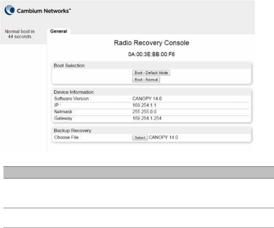
Chapter 9: Operation Radio Recovery
Page 9-73
Procedure 34 Radio Recovery Console
1 Apply power to PSU for at least 10 seconds.
2 Remove power from the PSU, and then re-apply it as soon as the power indicator light
goes out (about 1 - 2 seconds).
3 When the unit is in recovery mode, access the web interface by entering the default IP
address 169.254.1.1. The Recovery Image Warning page is displayed.
4 Review the Boot Selection (Table 228).
5 Select a recovery option
Figure 186 Recovery Options page
Table 228 Recovery Options attributes
Attribute Meaning
Boot Selection Boot – Default Mode: Use this option to temporarily set the IP and
Ethernet attributes to factory defaults until the next reboot.
Boot – Normal: Use this option to reboot the unit.
IP address, Netmask,
Gateway
These fields display IP address, Netmask and Gateway of the radio while
it is in recovery or default mode.

Chapter 9: Operation Radio Recovery
Page 9-74
Note
The radio enters recovery mode when a short power cycle is used. The radio will boot
normally if power has been removed for a longer period (typically 5 - 10 seconds).
Default Mode (or Default/Override Plug) - PMP/PTP 450 Series
The default modeallows to temporarily override some PMP/PTP 450 Series ODU settings and
thereby regain control of the module by powering the module on with the Default Plug inserted
into the unit’s synchronization (RJ11) port.
This override plug is needed for access to the module in any of the following cases:
You have forgotten either
o the IP address assigned to the ODU.
o the password that provides access to the ODU.
The ODU has been locked by the No Remote Access feature.
You want local access to a module that has had the 802.3 link disabled in the Configuration
page.
You can configure the module such that, when it senses the override plug, it responds by either
resetting the LAN1 IP address to 169.254.1.1, allowing access through the default configuration
without changing the configuration, whereupon you will be able to view and reset any non-
default values as you wish.
resetting all configurable parameters to their factory default values.
Note
The Default Plug is available from Best-Tronics Manufacturing, Inc.
See http://www.best-tronics.com/cambium.htm as Part BT-0583 (RJ-11 Default Plug).
Alternatively, you can fabricate an override plug. See Override plug cable on page 5-15
for pinout.

Chapter 9: Operation Radio Recovery
Page 9-75
Using the Default/Override Plug
The following section details usage of the override plug to regain access to PMP/PTP 450 Series
ODU.
Note
While the override plug is connected to a PMP/PTP 450 Series ODU, the ODU can
neither register nor allow registration of another ODU.
Note
Since the 900 MHz SM is based on the 450 Series, it only supports the "Default Plug"
mode of overriding.
Use below procedure to enter in default mode manually.
Procedure 35 Default mode
1 Insert the override plug into the RJ-11 GPS utility port of the module.
2 Power cycle by removing, then re-inserting, the Ethernet cable.
RESULT: The module boots with the default IP address of 169.254.1.1, password
fields blank, and all other configuration values as previously set.
3 Wait approximately 30 seconds for the boot to complete.
4 Remove the override plug.
5 Set passwords and IP address as desired.
6 Change configuration values if desired.
7 Click the Save Changes button.
8 Click the Reboot button.

Page 10-1
Chapter 10: Reference Information
This chapter contains reference information and regulatory notices that apply to the 450 Platform
Family ODUs.
The following topics are described in this chapter:
Equipment specifications on page 10-2 contains specifications of the 450 Platform Family, ODU
specifications including RF bands, channel width and link loss.
Data network specifications on page 10-33 shows the 450 Platform Family Ethernet interface
specifications.
Compliance with safety standards on page 4-22 lists the safety specifications against which 450
Platform Family ODU has been tested and certified. It also describes how to keep RF exposure
within safe limits.
Country specific radio regulations on page 10-36 describes how the 450 Platform Family
complies with the radio regulations that are enforced in various countries.
Equipment Disposal on page 10-38 describes the Equipment Disposal system for Electronic
and Electric Equipment.

Chapter 10: Reference Information Equipment specifications
Page 10-2
Equipment specifications
This section contains specifications of the AP, SM, BHM and BHS associated supplies required for
450 Platform Family installations.
Specifications for PMP 450m Series - AP
The PMP 450m AP conforms to the specifications listed in Table 229.
Table 229 PMP 450m Series - AP specifications
Category Specification
Model Number PMP 450m AP
Spectrum
Channel Spacing Configurable on 2.5 MHz increments
Frequency Range 5150 to 5925 MHz
Channel Bandwidth 20 MHz
Interface
MAC (Media Access
Control) Layer
Cambium Proprietary
Physical Layer 14x14 Multi-User MIMO OFDM
Ethernet Interface 100/1000BaseT, half/full duplex, rate auto negotiated
(802.3 compliant)
Protocols Used IPv4, UDP, TCP, IP, ICMP, Telnet, SNMP, HTTP, FTP
Network Management HTTP, HTTPS, Telnet, FTP, SNMP v3
VLAN 802.1ad (DVLAN Q-in-Q), 802.1Q with 802.1p priority,
dynamic port VID
Sensitivity
Nominal Receive
Sensitivity (w/ FEC) @
20 MHz Channel
5.8 GHz 1x = - 93.5 dBm, 2x = -88.6 dBm, 4x = -81.5 dBm, 6x = -
75.9.0 dBm, 8x = -67.8 dBm
5.4 GHz 1x = - 93.0 dBm, 2x = -88.2 dBm, 4x = -82.1 dBm, 6x = -
76.0 dBm, 8x = -68.2 dBm
Performance

Chapter 10: Reference Information Equipment specifications
Page 10-3
Subscriber Per Sector Up to 238
ARQ Yes
Cyclic Prefix 1/16
Frame Period 2.5 ms
Modulation Levels (Adaptive) Modulation
Levels
MCS SNR (in dB)
2x QPSK 10
4x 16QAM 17
6x 64QAM 24
8x 256QAM 32
Latency 10 ms, typical (MU-MIMO introduces additional latency
only for the low priority traffic)
Maximum Deployment Range Up to 40 miles (64 km)
GPS Synchronization Yes, via Autosync (UGPS)
Quality of Service Diffserv QoS
Link Budget
Antenna Beam Width 5 GHz 90° integrated sector (Dual polarity, H+V)
Antenna Gain +14 dBi
Maximum Transmit
Power
+24 dBm combined
Physical
Data, Sync/AUX and
SFP port
RJ45 1000BASE-T Ethernet Data
AUX port for uGPS or PoE out to 802.3at
Antenna Connection Integrated Sector Array
Surge Suppression
(with LPU)
EN61000-4-5: 1.2 us/50 us, 500 V voltage waveform
Recommended external surge suppressor:
Cambium Networks Model # C000065L007A
Mean Time Between
Failure
> 40 Years
Environmental IP66, IP67

Chapter 10: Reference Information Equipment specifications
Page 10-4
Temperature /
Humidity
-40°C to +60°C (-40°F to +140°F)
0-95% non-condensing
Weight Integrated Approx. 14.2 kg (31 bs)
Wind Loading – Front
Facing
@90 mph / 144 kph 460 N
@110 mph /177 kph 700 N
Dimension (HxWxD) Integrated 52 x 65 x 11 cm (20.3” x 25.7” x 4.4”)
Power Consumption 70 W typical, 80 W peak
(up to 110 W max with AUX port PoE enabled)
Input Voltage 58 V, 1.7 A
Mounting Pole mount with included brackets
Security
Encryption 56-bit DES, FIPS-197 128-bit AES
(*) 5.1 and 5.2 bands are not supported in 15.0.1 release.

Chapter 10: Reference Information Equipment specifications
Page 10-5
Specifications for PMP 450i Series - AP
The PMP 450i AP conforms to the specifications listed in Table 230.
Table 230 PMP 450i Series - AP specifications
Category Specification
Model Number PMP 450i AP
Spectrum
Channel Spacing 5, 7, 10, 15, 20 and 30 MHz Channel Bandwidth
Configurable on 2.5 MHz increments
Frequency Range 902 to 928 MHz
3300 - 3900 MHz
4900 - 5925 MHz
Channel Bandwidth 902 – 928 MHz
5, 7, 10 and 20 MHz
3300 - 3900
MHz
5, 7, 10, 15, 20, 30, and 40 MHz
4900 – 5925
MHz
5, 10, 15, 20 and 30 MHz
(5.4 and 5.8 GHz – 40 MHz)
Interface
MAC (Media Access
Control) Layer
Cambium Proprietary
Physical Layer 2x2 MIMO OFDM
Ethernet Interface 10/100/1000BaseT, half/full duplex, rate auto negotiated
(802.3 compliant)
Protocols Used IPv4, UDP, TCP, IP, ICMP, Telnet, SNMP, HTTP, FTP
Network Management HTTP, HTTPS, Telnet, FTP, SNMP v3
VLAN 802.1ad (DVLAN Q-in-Q), 802.1Q with 802.1p priority,
dynamic port VID
Sensitivity
Nominal Receive
Sensitivity (w/ FEC) @
5 MHz Channel
900 MHz 1x = -91.9 dBm, 2x = -86.7 dBm, 4x = -80.9 dBm, 6x = -
75 dBm, 8x = -68.8 dBm
4.9 GHz 1x = -91.6 dBm, 2x = -87.6 dBm, 4x = -80.4 dBm, 6x = -
73.2 dBm, 8x = -66 dBm

Chapter 10: Reference Information Equipment specifications
Page 10-6
5.4 GHz 1x = -92 dBm, 2x = -87 dBm, 4x = -80.8 dBm, 6x = -73.7
dBm, 8x = -66.6 dBm
5.8 GHz 1x = -91.5 dBm, 2x = -87 dBm, 4x = -80.2 dBm, 6x = -
73.1 dBm, 8x = -66 dBm
Nominal Receive
Sensitivity (w/ FEC) @
7 MHz Channel
900 MHz 1x = -90 dBm, 2x = -85.9 dBm, 4x = -79.8 dBm, 6x = -
73.6 dBm, 8x = -67.9 dBm
Nominal Receive
Sensitivity (w/ FEC) @
10 MHz Channel
900 MHz 1x = -90.6 dBm, 2x = -85.2 dBm, 4x = -79.1 dBm, 6x = -
73.2 dBm, 8x = -66.2 dBm
4.9 GHz 1x = -89.1 dBm, 2x = -85 dBm, 4x = -77.9 dBm, 6x = -
71.8 dBm, 8x = -64.6 dBm
5.4 GHz 1x = -89.5 dBm, 2x = -85.4 dBm, 4x = -78.2 dBm, 6x = -
72.2 dBm, 8x = -64.8 dBm
5.8 GHz 1x = -89.5 dBm, 2x = -84.7 dBm, 4x = -77.8 dBm, 6x = -
71.6 dBm, 8x = -64 dBm
Nominal Receive
Sensitivity (w/ FEC) @
15 MHz Channel
4.9 GHz 1x = -87.2 dBm, 2x = -83 dBm, 4x = -75.8 dBm, 6x = -
69.6 dBm, 8x = -62.6 dBm
5.4 GHz 1x = -87.2 dBm, 2x = -83.3 dBm, 4x = -76.2 dBm, 6x = -
70.1 dBm, 8x = -63 dBm
5.8 GHz 1x = -87.7 dBm, 2x = -82.7 dBm, 4x = -75.5 dBm, 6x = -
69.6 dBm, 8x = -62.4 dBm
Nominal Receive
Sensitivity (w/ FEC) @
20 MHz Channel
900 MHz 1x = -86.99 dBm, 2x = -82 dBm, 4x = -75.9 dBm, 6x = -
69.9 dBm, 8x = -62.9 dBm
4.9 GHz 1x = -86.1 dBm, 2x = -82.1 dBm, 4x = -74.8 dBm, 6x = -
68.8 dBm, 8x = -61.7 dBm
5.4 GHz 1x = -86.6 dBm, 2x = -81.3 dBm, 4x = -75.5 dBm, 6x = -
68.6 dBm, 8x = -62 dBm
5.8 GHz 1x = -85.8 dBm, 2x = -80.7 dBm, 4x = -74.6 dBm, 6x = -
68.7 dBm, 8x = -61 dBm
4.9 GHz 1x = -84.1 dBm, 2x = -80 dBm, 4x = -73 dBm, 6x = -66.4
dBm, 8x = -59.6 dBm

Chapter 10: Reference Information Equipment specifications
Page 10-7
Nominal Receive
Sensitivity (w/ FEC) @
30 MHz Channel
5.4 GHz 1x = -84.5 dBm, 2x = -82 dBm, 4x = -75 3.5Bm, 6x = -
67.4 dBm, 8x = -60.2 dBm
5.8 GHz 1x = -84.1 dBm, 2x = -80 dBm, 4x = -73 dBm, 6x = -66.5
dBm, 8x = -59.4 dBm
Performance
ARQ Yes
Cyclic Prefix 1/16
Frame Period 2.5 ms or 5.0 ms
Modulation Levels
(Adaptive)
Modulation
Levels
MCS SNR (in dB)
2x QPSK 10
4x 16QAM 17
6x 64QAM 24
8x 256QAM 32
Latency 3 - 5 ms
Maximum Deployment
Range
Up to 40 miles (64 km)
GPS Synchronization Yes, via Autosync (CMM4), via UGPS
Quality of Service Diffserv QoS
Link Budget
Antenna Beam Width 900 MHz 65° sector antenna (Dual Slant)
5 GHz 90° (3 dB roll off) sector for integrated (Dual polarity,
H+V)
Antenna Gain (Does
not include cable loss,
~1dB)
900 MHz 13 dBi
5 GHz 17 dBi integrated 90° sector or external
Transmit Power Range 40 dB dynamic range (to EIRP limit by region) (1 dB
step)
Maximum Transmit
Power
+27 dBm combined output (for 5 GHz)
+25 dBm combined output (for 900MHz)
Physical

Chapter 10: Reference Information Equipment specifications
Page 10-8
Sync/AUX port RJ45 10/100/100BASE-T Ethernet Data
PoE output (planned for future release)
Sync input or output (Connection and powering of
UGPS Sync input)
Antenna Connection 50 ohm, N-type (Connectorized version only)
Surge Suppression
EN61000-4-5
EN61000-4-5: 1.2 us/50 us, 500 V voltage waveform
Recommended external surge suppressor: Cambium
Networks Model # C000000L033A
Mean Time Between
Failure
> 40 Years
Environmental IP66, IP67
Temperature /
Humidity
-40°C to +60°C (-40°F to +140°F), 0-95% non-
condensing
Weight Connectorized
Approx. 2.0 kg (4.5 lbs)
Integrated Approx. 2.5 kg (5.5 lbs)
Wind Survival Connectorized 322 km/h (200 mi/h)
Integrated 200 km/h (124 mi/h)
Dimension(HxWxD) Connectorized
26.0 x 13.4 x 6.4 cm (10.3” x 5.3” x 3.3”)
Integrated 37.0 x 37.0 x 6.3 cm (14.5” x 14.5” x 3.2”)
Power Consumption 15 W typical, 25 W max, 55 W max with Aux port PoE
out enabled
Input Voltage 48-59 V DC, 802.3at compliant
Mounting Wall or Pole mount with Cambium Networks Model #
N000045L002A
Security
Encryption 56-bit DES, FIPS-197 128-bit AES

Chapter 10: Reference Information Equipment specifications
Page 10-9
Specifications for PMP 450i Series - SM
The PMP 450i SM conforms to the specifications listed in Table 231.
Table 231 PMP 450i Series - SM specifications
Category Specification
Model Number PMP 450i SM
Spectrum
Channel Spacing 5, 7, 10, 15, 20 and 30 Channel Bandwidth
Configurable on 2.5 MHz increments
Frequency Range 3300 – 3900 MHz
4900 - 5925 MHz
Channel Bandwidth 3300 – 3900
MHz
5, 7, 10, 15, 20 and 30 MHz
4900 – 5925
MHz
5, 10, 15, 20 and 30 MHz
Interface
MAC (Media Access
Control) Layer
Cambium Proprietary
Physical Layer 2x2 MIMO OFDM
Ethernet Interface 10/100/1000BaseT, half/full duplex, rate auto negotiated
(802.3 compliant)
Protocols Used IPv4, UDP, TCP, IP, ICMP, Telnet, SNMP, HTTP, FTP
Network Management HTTP, HTTPS, Telnet, FTP, SNMP v2c and v3
VLAN 802.1ad (DVLAN Q-in-Q), 802.1Q with 802.1p priority,
dynamic port VID
Sensitivity
Nominal Receive
Sensitivity (w/ FEC) @
5 MHz Channel
4.9 GHz 1x = -92.5 dBm, 2x = -88.5 dBm, 4x = -81 dBm, 6x = -
74.2 dBm, 8x = -66 dBm
5.4 GHz 1x = -93 dBm, 2x = -89.1 dBm, 4x = -81.5 dBm, 6x = -
74.8 dBm, 8x = -67.4 dBm
5.8 GHz 1x = -92 dBm, 2x = -88.3 dBm, 4x = -80.8 dBm, 6x = -74
dBm, 8x = -66.2 dBm

Chapter 10: Reference Information Equipment specifications
Page 10-10
Nominal Receive
Sensitivity (w/ FEC) @
10 MHz Channel
4.9 GHz 1x = -90.2 dBm, 2x = -85.2 dBm, 4x = -78.8 dBm, 6x = -
71.4 dBm, 8x = -64.5 dBm
5.4 GHz 1x = -90 dBm, 2x = -85.8 dBm, 4x = -78.5 dBm, 6x = -
72.2 dBm, 8x = -65.8 dBm
5.8 GHz 1x = -89.9 dBm, 2x = -84.9 dBm, 4x = -78.5 dBm, 6x = -
71.2 dBm, 8x = -63.8 dBm
Nominal Receive
Sensitivity (w/ FEC) @
15 MHz Channel
4.9 GHz 1x = -88.2 dBm, 2x = -83.1 dBm, 4x = -76.9 dBm, 6x = -
70.5 dBm, 8x = -62.3 dBm
5.4 GHz 1x = -87.7 dBm, 2x = -83.9 dBm, 4x = -76.6 dBm, 6x = -
70.4 dBm, 8x = -63 dBm
5.8 GHz 1x = -88 dBm, 2x = -82.9 dBm, 4x = -76.7 dBm, 6x = -
69.4 dBm, 8x = -62.3 dBm
Nominal Receive
Sensitivity (w/ FEC) @
20 MHz Channel
4.9 GHz 1x = -87 dBm, 2x = -81.8 dBm, 4x = -75.8 dBm, 6x = -
68.5 dBm, 8x = -61.4 dBm
5.4 GHz 1x = -87 dBm, 2x = -82.8 dBm, 4x = -75.6 dBm, 6x = -
69.3 dBm, 8x = -61.6 dBm
5.8 GHz 1x = -85.9 dBm, 2x = -81.5 dBm, 4x = -74.8 dBm, 6x = -
68.7 dBm, 8x = -61.2 dBm
Nominal Receive
Sensitivity (w/ FEC) @
30 MHz Channel
4.9 GHz 1x = -84.9 dBm, 2x = -80.9 dBm, 4x = -73.2 dBm, 6x = -
67.4 dBm, 8x = -59.3 dBm
5.4 GHz 1x = -85.2 dBm, 2x = -80.2 dBm, 4x = -74.1 dBm, 6x = -
67.9 dBm, 8x = -59.8 dBm
5.8 GHz 1x = -84.9 dBm, 2x = -80 dBm, 4x = -73.2 dBm, 6x = -
67.4 dBm, 8x = -59.4 dBm
Performance
ARQ Yes
Cyclic Prefix 1/16
Frame Period 2.5 ms or 5.0 ms
Modulation Levels
(Adaptive)
Modulation Levels MCS SNR (in dB)
2x QPSK 10

Chapter 10: Reference Information Equipment specifications
Page 10-11
4x 16QAM 17
6x 64QAM 24
8x 256QAM 32
Latency 3 - 5 ms
Maximum Deployment
Range
Up to 40 miles (64 km)
GPS Synchronization Yes, via Autosync (CMM4)
Quality of Service Diffserv QoS
Link Budget
Antenna Beam Width 10° azimuth for 23 dBi integrated antenna
Antenna Gain (Does
not include cable loss,
~1dB)
5 GHz +23 dBi H+V, integrated or external
Transmit Power Range 40 dB dynamic range (to EIRP limit by region) (1 dB
step)
Maximum Transmit
Power
+27 dBm combined output (for 5 GHz)
Physical
Sync/AUX port RJ45 10/100/1000BASE-T Ethernet Data
PoE output (planned for future release)
Sync input or output (Connection and powering of
UGPS Sync input)
Antenna Connection 50 ohm, N-type (Connectorized version only)
Surge Suppression
EN61000-4-5
EN61000-4-5: 1.2us/50us, 500 V voltage waveform
Recommended external surge suppressor: Cambium
Networks Model # C000000L033A
Mean Time Between
Failure
> 40 Years
Environmental IP66, IP67
Temperature /
Humidity
-40°C to +60°C (-40°F to +140°F), 0-95% non-
condensing
Weight Connectorized
Approx. 2.0 kg (4.5 lbs)
Integrated Approx. 2.5 kg (5.5 lbs)

Chapter 10: Reference Information Equipment specifications
Page 10-12
Wind Survival Connectorized 322 km/h (200 mi/h)
Integrated 200 km/h (124 mi/h)
Dimension(HxWxD) Connectorized
26.0 x 13.4 x 6.4 cm (10.3” x 5.3” x 3.3”)
Integrated 31.0 x 31.0 x 6.4 cm (12” x 12” x 2.5”)
Power Consumption 15 W typical, 25 W max, 55 W max with Aux port PoE
out enabled
Input Voltage 48-59 V DC, 802.3at compliant
Mounting Wall or Pole mount with Cambium Networks Model #
N000045L002A
Security
Encryption 56-bit DES, FIPS-197 128-bit AES

Chapter 10: Reference Information Equipment specifications
Page 10-13
Specifications for PTP 450i Series - BH
The PTP 450i BH conforms to the specifications listed in Table 232.
Table 232 PTP 450i Series - BH specifications
Category Specification
Model Number PTP 450i BH
Spectrum
Channel Spacing 5, 10, 15, 20 and 30 MHz Channel Bandwidth
Configurable on 2.5 MHz increments
Frequency Range 902 to 928 MHz
4900 - 5925 MHz
Channel Bandwidth 902 – 928 MHz
5, 7, 10 and 20 MHz
4900 – 5925
MHz
5, 10, 15, 20 and 30 MHz
Interface
MAC (Media Access
Control) Layer
Cambium Proprietary
Physical Layer 2x2 MIMO OFDM
Ethernet Interface 10/100/1000BaseT, half/full duplex, rate auto negotiated
(802.3 compliant)
Protocols Used IPv4, UDP, TCP, IP, ICMP, Telnet, SNMP, HTTP, FTP
Network Management HTTP, HTTPS, Telnet, FTP, SNMP v2c and v3
VLAN 802.1ad (DVLAN Q-in-Q), 802.1Q with 802.1p priority,
dynamic port VID
Sensitivity
Nominal Receive
Sensitivity (w/ FEC) @
5 MHz Channel
900 MHz 1x = -93 dBm, 2x = -88 dBm, 4x = -81 dBm, 6x = -75
dBm, 8x = -68 dBm
4.9 GHz 1x = -93 dBm, 2x = -88.3 dBm, 4x = -82 dBm, 6x = -74.4
dBm, 8x = -67.9 dBm
5.4 GHz 1x = -93 dBm, 2x = -88.4 dBm, 4x = -81.3 dBm, 6x = -
75.5 dBm, 8x = -67.8 dBm
5.8 GHz 1x = -93.2 dBm, 2x = -88.3 dBm, 4x = -80.8 dBm, 6x = -
74.3 dBm, 8x = -66.8 dBm

Chapter 10: Reference Information Equipment specifications
Page 10-14
Nominal Receive
Sensitivity (w/ FEC) @
7 MHz Channel
900 MHz 1x = -91 dBm, 2x = -86 dBm, 4x = -80 dBm, 6x = -74
dBm, 8x = -67 dBm
Nominal Receive
Sensitivity (w/ FEC) @
10 MHz Channel
900 MHz 1x = -90 dBm, 2x = -84 dBm, 4x = -79 dBm, 6x = -73
dBm, 8x = -66 dBm
4.9 GHz 1x = -90 dBm, 2x = -85 dBm, 4x = -78.6 dBm, 6x = -
72.5dBm, 8x = -65 dBm
5.4 GHz 1x = -87.6 dBm, 2x = -82.5 dBm, 4x = -76.5 dBm, 6x = -
70.5 dBm, 8x = -61.5dBm
5.8 GHz 1x = -89.9 dBm, 2x = -84.8 dBm, 4x = -78.5 dBm, 6x = -
71.4 dBm, 8x = -64 dBm
Nominal Receive
Sensitivity (w/ FEC) @
15 MHz Channel
4.9 GHz 1x = -88 dBm, 2x = -83.9 dBm, 4x = -76.9 dBm, 6x = -
70.7 dBm, 8x = -63.6 dBm
5.4 GHz 1x = -88 dBm, 2x = -84.2 dBm, 4x = -76.9 dBm, 6x = -
70.8 dBm, 8x = -62.7 dBm
5.8 GHz 1x = -87.8 dBm, 2x = -82.8 dBm, 4x = -6.6 dBm, 6x =
69.3 dBm, 8x = -62.1 dBm
Nominal Receive
Sensitivity (w/ FEC) @
20 MHz Channel
900 MHz 1x = -86 dBm, 2x = -82 dBm, 4x = -75 dBm, 6x = -69
dBm, 8x = -62 dBm
4.9 GHz 1x = -86.9 dBm, 2x = -82.5 dBm, 4x = -75.7 dBm, 6x = -
69.4 dBm, 8x = -62.3 dBm
5.4 GHz 1x = -84.5 dBm, 2x = -80.5 dBm, 4x = -73.4 dBm, 6x = -
66.4 dBm, 8x = -56.4 dBm
5.8 GHz 1x = -85.8 dBm, 2x = -81.7 dBm, 4x = -75 dBm, 6x = -
68.4 dBm, 8x = -61.2 dBm
Nominal Receive
Sensitivity (w/ FEC) @
30 MHz Channel
4.9 GHz 1x = -85 dBm, 2x = -80.7 dBm, 4x = -73.7 dBm, 6x = -
66.5 dBm, 8x = -60 dBm
5.4 GHz 1x = -85.3 dBm, 2x = -80.5 dBm, 4x = -74.2 dBm, 6x = -
67.2 dBm, 8x = -60 dBm
5.8 GHz 1x = -84.6 dBm, 2x = -80 dBm, 4x = -73,3 dBm, 6x = -
66.5 dBm, 8x = -59.1 dBm
Performance
ARQ Yes
Cyclic Prefix 1/16
Frame Period 2.5 ms or 5.0 ms
Modulation Levels
(Adaptive)
Modulation Levels MCS SNR (in dB)
2x QPSK 10

Chapter 10: Reference Information Equipment specifications
Page 10-15
4x 16QAM 17
6x 64QAM 24
8x 256QAM 32
Latency 3 - 5 ms
Maximum Deployment
Range
Up to 40 miles (64 km)
GPS Synchronization Yes, via Autosync (CMM4)
Quality of Service Diffserv QoS
Link Budget
Antenna Beam Width 900 MHz 37° azimuth for 12 dBi Yagi antenna
5 GHz 10° azimuth for 23 dBi integrated antenna
Antenna Gain (Does
not include cable loss,
~1dB)
900 MHz 12 dBi Yagi antenna
5 GHz +23 dBi H+V, integrated or external
Transmit Power Range 40 dB dynamic range (to EIRP limit by region) (1 dB
step)
Maximum Transmit
Power
+27 dBm combined output
Physical
Sync/AUX port RJ45 10/100/1000BASE-T Ethernet Data
PoE output
Sync input or output (Connection and powering of
UGPS Sync input)
Antenna Connection 50 ohm, N-type (Connectorized version only)
Surge Suppression
EN61000-4-5
EN61000-4-5: 1.2us/50us, 500 V voltage waveform
Recommended external surge suppressor: Cambium
Networks Model # C000000L033A
Mean Time Between
Failure
> 40 Years
Environmental IP66, IP67
Temperature /
Humidity
-40°C to +60°C (-40°F to +140°F), 0-95% non-
condensing
Weight Connectorized
Approx. 2.0 kg (4.5 lbs)

Chapter 10: Reference Information Equipment specifications
Page 10-16
Integrated Approx. 2.5 kg (5.5 lbs)
Wind Survival Connectorized 322 km/h (200 mi/h)
Integrated 200 km/h (124 mi/h)
Dimension(HxWxD) Connectorized
26.0 x 13.4 x 6.4 cm (10.25” x 5.25” x 3.25”)
Integrated 31.0 x 31.0 x 6.4 cm (12” x 12” x 2.5”)
Power Consumption 15 W typical, 25 W max, 55 W max with Aux port PoE
out enabled
Input Voltage 48-59 V DC, 802.3at compliant
Mounting Wall or Pole mount with Cambium Networks Model #
N000045L002A
Security
Encryption 56-bit DES, FIPS-197 128-bit AES

Chapter 10: Reference Information Equipment specifications
Page 10-17
Specifications for PMP 450 Series - AP
The PMP 450 AP conforms to the specifications listed in Table 233.
Table 233 PMP 450 Series - AP specifications
Category Specification
Model Number PMP 450 AP
Spectrum
Channel Spacing 5, 7, 10, 15, 20 and 30 MHz Channel Bandwidth
Configurable on 2.5 MHz increments
Frequency Range 2.4 GHz 2400 – 2483.5 MHz
3.5 GHz 3300 – 3600 MHz
3.65 GHz 3500 – 3850 MHz
5 GHz 5470 – 5875 MHz
Channel Bandwidth 3.5 and 3.65 GHz 5, 7, 10, 15, 20 and 30 MHz
2.4 and 5 GHz 5, 10, 15, 20 and 30 MHz
OFDM Subcarriers 512 FFT
Interface
MAC (Media Access
Control) Layer
Cambium Proprietary
Physical Layer 2x2 MIMO OFDM
Ethernet Interface 10/100/1000BaseT, half/full duplex, rate auto
negotiated (802.3 compliant)
Protocols Used IPv4, UDP, TCP, IP, ICMP, Telnet, SNMP, HTTP, FTP,
TFTP, RADIUS
Network Management HTTP, HTTPS, Telnet, FTP, SNMP v3, TFTP, Syslog
VLAN 802.1ad (DVLAN Q-in-Q), 802.1Q with 802.1p
priority, dynamic port VID
Sensitivity
Nominal Receive
Sensitivity (w/ FEC) @
5 MHz Channel
2.4 GHz
1x = -92 dBm, 2x = -87.8 dBm, 4x = -80.4 dBm, 6x =
-74.4 dBm, 8x = -66.5 dBm
3.5 GHz 1x = -92.4 dBm, 2x = -88.3 dBm, 4x = -81.3 dBm, 6x
= -75.3 dBm, 8x = -67.7 dBm

Chapter 10: Reference Information Equipment specifications
Page 10-18
3.65 GHz 1x = -10 dBm, 2x = -86.1 dBm, 4x = -80.2 dBm, 6x =
-73.1 dBm, 8x = -66 dBm
5.4 GHz 1x = -88.7 dBm, 2x = -84 dBm, 4x = -77.6 dBm, 6x =
-71.6 dBm, 8x = -63.7 dBm
5.8 GHz 1x = -91.5 dBm, 2x = -87 dBm, 4x = -80.2 dBm, 6x =
-73.1 dBm, 8x = -66 dBm
Nominal Receive
Sensitivity (w/ FEC) @
7 MHz Channel
3.5 GHz 1x = -90.5 dBm, 2x = -86.4 dBm, 4x = -80.3 dBm, 6x
= -73.4 dBm, 8x = -66.9 dBm
3.65 GHz 1x = -89.1 dBm, 2x = -85.1 dBm, 4x = -78.1 dBm, 6x
= -72.1 dBm, 8x = -64.5 dBm
Nominal Receive
Sensitivity (w/ FEC) @
10 MHz Channel
2.4 GHz 1x = -89.9 dBm, 2x = -85.6 dBm, 4x = -80 dBm, 6x =
-73.5 dBm, 8x = -66.9 dBm
3.5 GHz 1x = -89.8 dBm, 2x = -85.6 dBm, 4x = -80 dBm, 6x =
-73 dBm, 8x = -66.3 dBm
3.65 GHz 1x = -89 dBm, 2x = -85.2 dBm, 4x = -78.1 dBm, 6x =
-72.1 dBm, 8x = -64.5 dBm
5.4 GHz 1x = -86.1 dBm, 2x = -82.2 dBm, 4x = -75.3 dBm, 6x
= -69.3 dBm, 8x = -61.3 dBm
5.8 GHz 1x = -86 dBm, 2x = -82.2 dBm, 4x = -75.1 dBm, 6x =
-69 dBm, 8x = -60 dBm
Nominal Receive
Sensitivity (w/ FEC) @
15 MHz Channel
2.4 GHz 1x = -88.4 dBm, 2x = -84.1 dBm, 4x = -77.1 dBm, 6x
= -71.4 dBm, 8x = -65 dBm
3.5 GHz 1x = -88.5 dBm, 2x = -84.5 dBm, 4x = -77.5 dBm, 6x
= -71.5 dBm, 8x = -64.3 dBm
3.65 GHz 1x = -87.4 dBm, 2x = -83.7 dBm, 4x = -76.3 dBm, 6x
= -69.7 dBm, 8x = -62.2 dBm
5.4 GHz 1x = -84.2 dBm, 2x = -80.2 dBm, 4x = -73.2 dBm, 6x
= -67.2 dBm, 8x = -60 dBm
5.8 GHz 1x = -85 dBm, 2x = -80 dBm, 4x = -74.3 dBm, 6x = -
67 dBm, 8x = -58 dBm
Nominal Receive
Sensitivity (w/ FEC) @
20 MHz Channel
2.4 GHz 1x = -85 dBm, 2x = -85 dBm, 4x = -79 dBm, 6x = -72
dBm, 8x = -66 dBm
3.5 GHz 1x = -85 dBm, 2x = -85 dBm, 4x = -79 dBm, 6x = -72
dBm, 8x = -65 dBm
3.65 GHz 1x = -86 dBm, 2x = -86 dBm, 4x = -78 dBm, 6x = -71
dBm, 8x = -63 dBm

Chapter 10: Reference Information Equipment specifications
Page 10-19
5.4 GHz 1x = -81 dBm, 2x = -81 dBm, 4x = -75 dBm, 6x = -68
dBm, 8x = -59 dBm
5.8 GHz 1x = -82 dBm, 2x = -82 dBm, 4x = -75 dBm, 6x = -69
dBm, 8x = -60 dBm
Nominal Receive
Sensitivity (w/ FEC) @
30 MHz Channel
2.4 GHz 1x = -85.4 dBm, 2x = -80.4 dBm, 4x = -74 dBm, 6x =
-68 dBm, 8x = -61 dBm
3.5 GHz 1x = -85.5 dBm, 2x = -81.5 dBm, 4x = -74.5 dBm, 6x
= -68.2 dBm, 8x = -61.3 dBm
3.65 GHz 1x = -84 dBm, 2x = -79.5 dBm, 4x = -73.4 dBm, 6x =
-66.4 dBm, 8x = -59.2 dBm
5.4 GHz 1x = -81 dBm, 2x = -76.9 dBm, 4x = -70.9 dBm, 6x =
-63.8 dBm, 8x = -55.8 dBm
5.8 GHz 1x = -80.9 dBm, 2x = -76.8 dBm, 4x = -70 dBm, 6x =
-63.8 dBm, 8x = -55 dBm
Performance
Subscribers Per Sector Up to 238
ARQ Yes
Cyclic Prefix 1/16
Frame Period 2.5 ms or 5.0 ms
Modulation Levels
(Adaptive)
Modulation
Levels
MCS SNR (in dB)
2x QPSK 10
4x 16QAM 17
6x 64QAM 24
8x 256QAM 32
Latency 3 - 5 ms for 2.5 ms Frame Period
6-10 ms for 5.0 ms Frame Period
Maximum Deployment Range Up to 40 miles (64 km)
Packets Per Second 12,500
GPS Synchronization Yes, via CMM3, CMM4 or UGPS
Quality of Service Diffserv QoS
Link Budget

Chapter 10: Reference Information Equipment specifications
Page 10-20
Antenna Gain (Does
not include cable loss,
~1dB)
2.4 GHz 18 dBi Dual Slant
3.5 GHz 16 dBi Dual Slant
3.65 GHz 16 dBi Dual Slant
5 GHz 17 dBi Horizontal and Vertical
Combined Transmit
Power
-30 to +22 dBm (to EIRP limit by region) in 1 dB-
configurable intervals (2.4 GHz, 5 GHz)
-30 to +25 dBm (to EIRP limit by region) in 1 dB-
configurable intervals (3.5 GHz)
-30 to +25 dBm (to EIRP limit by region and channel
bandwidth) in 1 dB-configurable intervals (3.6 GHz)
Maximum Transmit
Power
22 dBm combined OFDM (2.4 GHz, 5 GHz)
(dependent upon Region Code setting)
25 dBm combined OFDM (3.5 GHz, 3.6 GHz),
(dependent upon Region Code setting)
Physical
Wind Survival 200 mph (322 kph)
Antenna Connection 50 ohm, N-type (Connectorized version only)
Environmental IP66, IP67
Temperature / Humidity -40°C to +60°C (-40°F to +140°F) /
0-95% non-condensing
Weight 2.4 GHz 15 kg (33 lbs) with antenna
2.5 kg (5.5 lbs) without antenna
3.5 GHz 15 kg (33 lbs) with antenna
2.5 kg (5.5 lbs) without antenna
3.6 GHz 15 kg (33 lbs) with antenna
2.5 kg (5.5 lbs) without antenna
5 GHz 5.9 kg (13 lbs) with antenna
2.5 kg (5.5 lbs) without antenna
Dimension(HxWxD) 2.4 GHz Radio: 27 x 21 x 7 cm (10.6” x 8.3” x 2.8”)
Antenna: 112.2 x 24.5 x 11.7 cm (44.2” x 9.6” x 4.6”)
3.5 GHz Radio: 27 x 21 x 7 cm (10.6” x 8.3” x 2.8”)
3.6 GHz Radio: 27 x 21 x 7 cm (10.6” x 8.3” x 2.8”)
5 GHz Radio: 27 x 21 x 7 cm (10.6” x 8.3” x 2.8”)

Chapter 10: Reference Information Equipment specifications
Page 10-21
Antenna: 51 x 13 x 7.3 cm (20.2” x 5.1” x 2.9”)
Power Consumption 14 W
Input Voltage 22 to 32 VDC
Security
Encryption 56-bit DES, AES

Chapter 10: Reference Information Equipment specifications
Page 10-22
Specifications for PMP 450 Series - SM
The PMP 450 SM conforms to the specifications listed in Table 234.
Table 234 PMP 450 Series - SM specifications
Category Specification
Model Number PMP 450 SM
Spectrum
Channel Spacing 5, 7, 10, 15, 20 and 30 MHz Channel Bandwidth
Configurable on 2.5 MHz increments
Frequency Range 900 MHz 902 – 928 MHz
2.4 GHz 2400 – 2483.5 MHz
3.5 GHz 3300 – 3600 MHz
3.65 GHz 3500 – 3850 MHz
5 GHz 5470 – 5875 MHz
Channel Bandwidth 900 MHz, 5, 7, 10 and 20 MHz
2.4, 3.5 GHz, 3.65
GHz and 5 GHz
5, 10, 15, 20 and 30 MHz
(3.5, 3.65, 5.4, and 5.8 GHz – 40 MHz)
OFDM Subcarriers 512 FFT
Interface
MAC (Media Access Control) Layer Cambium Proprietary
Physical Layer 2x2 MIMO OFDM
Ethernet Interface 10/100 BaseT, half/full duplex, rate auto negotiated
(802.3 compliant)
Protocols Used IPv4, UDP, TCP, IP, ICMP, Telnet, SNMP, HTTP, FTP
Network Management HTTP, HTTPS, Telnet, FTP, SNMP v3
VLAN 802.1ad (DVLAN Q-in-Q), 802.1Q with 802.1p
priority, dynamic port VID
Sensitivity
900 MHz 1x = -91 dBm, 2x = -91 dBm, 4x = -85 dBm, 6x = -78
dBm, 8x = -70 dBm

Chapter 10: Reference Information Equipment specifications
Page 10-23
Nominal Receive
Sensitivity (w/ FEC) @
5 MHz Channel
2.4 GHz 1x = -92.5 dBm, 2x = -89.9 dBm, 4x = -82.9 dBm, 6x
= -75.9, dBm, 8x = -67.9 dBm
3.5 GHz 1x = -93.5 dBm, 2x = -89.4 dBm, 4x = -83.5 dBm, 6x
= -76.4 dBm, 8x = -68.3 dBm
3.65 GHz 1x = -91.3 dBm, 2x = -89.1 dBm, 4x = -82.2 dBm, 6x
= -75.2 dBm, 8x = -67.3 dBm
5.4 GHz 1x = -89.3 dBm, 2x = -87.3 dBm, 4x = -80.3 dBm, 6x
= -74.3 dBm, 8x = -66.3 dBm
5.8 GHz 1x = -89 dBm, 2x = -87 dBm, 4x = -80 dBm, 6x = -
73.9 dBm, 8x = -64.9 dBm
Nominal Receive
Sensitivity (w/ FEC) @
7 MHz Channel
900 MHz 1x = -91 dBm, 2x = -84 dBm, 4x = -83 dBm, 6x = -77
dBm, 8x = -71 dBm
3.5 GHz 1x = -92.2 dBm, 2x = -88.5 dBm, 4x = -81.4 dBm, 6x
= -74.5 dBm, 8x = -67.6 dBm
3.65 GHz 1x = -90.4 dBm, 2x = -87.3 dBm, 4x = -80.6 dBm, 6x
= -73 dBm, 8x = -65.6 dBm
Nominal Receive
Sensitivity (w/ FEC) @
10 MHz Channel
900 MHz 1x = -90 dBm, 2x = -83 dBm, 4x = -80 dBm, 6x = -74
dBm, 8x = -68 dBm
2.4 GHz 1x = -88 dBm, 2x = -88 dBm, 4x = -81 dBm, 6x = -75
dBm, 8x = -69 dBm
3.5 GHz 1x = -88 dBm, 2x = -88 dBm, 4x = -81 dBm, 6x = -76
dBm, 8x = -68 dBm
3.65 GHz 1x = -86 dBm, 2x = -86 dBm, 4x = -80 dBm, 6x = -73
dBm, 8x = -66 dBm
5.4 GHz 1x = -84 dBm, 2x = -84 dBm, 4x = -78 dBm, 6x = -72
dBm, 8x = -63 dBm
5.8 GHz 1x = -84 dBm, 2x = -84 dBm, 4x = -77 dBm, 6x = -71
dBm, 8x = -63 dBm
Nominal Receive
Sensitivity (w/ FEC) @
15 MHz Channel
2.4 GHz 1x = -88.5 dBm, 2x = -84.5 dBm, 4x = -77.5 dBm, 6x
= -71.5 dBm, 8x = -64.5 dBm
3.5 GHz 1x = -89.5 dBm, 2x = -84.5 dBm, 4x = -78.5 dBm, 6x
= -71.5 dBm, 8x = -65.1 dBm
3.65 GHz 1x = -87.3 dBm, 2x = -84.3 dBm, 4x = -77.3 dBm, 6x
= -70.3 dBm, 8x = -62.2 dBm
5.4 GHz 1x = -84.5dBm, 2x = -82.5 dBm, 4x = -75.5 dBm, 6x =
-69.5 dBm, 8x = -59.5 dBm

Chapter 10: Reference Information Equipment specifications
Page 10-24
5.8 GHz 1x = -84 dBm, 2x = -84 dBm, 4x = -77 dBm, 6x = -71
dBm, 8x = -63 dBm
Nominal Receive
Sensitivity (w/ FEC) @
20 MHz Channel
900 MHz 1x = -87 dBm, 2x = -80 dBm, 4x = -77 dBm, 6x = -72
dBm, 8x = -65 dBm
2.4 GHz 1x = -86.9 dBm, 2x = -82.9 dBm, 4x = -75.9 dBm, 6x
= -69.9 dBm, 8x = -63.5 dBm
3.5 GHz 1x = -87.5 dBm, 2x = -83.5 dBm, 4x = -76.5 dBm, 6x
= -69.5 dBm, 8x = -63.1 dBm
3.65 GHz 1x = -86 dBm, 2x = -83 dBm, 4x = -76.2 dBm, 6x = -
68.2 dBm, 8x = -61 dBm
5.4 GHz 1x = -83.4 dBm, 2x = -81.7 dBm, 4x = -74.4 dBm, 6x
= -67.2 dBm, 8x = -57.3 dBm
5.8 GHz 1x = -84 dBm, 2x = -80.5 dBm, 4x = -74 dBm, 6x = -
66.9 dBm, 8x = -56 dBm
Nominal Receive
Sensitivity (w/ FEC) @
30 MHz Channel
2.4 GHz 1x = -85.9 dBm, 2x = -80.9 dBm, 4x = -73.9 dBm, 6x
= -67.8 dBm, 8x = -60.9 dBm
3.5 GHz 1x = -86.5 dBm, 2x = -81.5 dBm, 4x = -74.5 dBm, 6x
= -68.2 dBm, 8x = -61.3 dBm
3.65 GHz 1x = -84.3 dBm, 2x = -80.3 dBm, 4x = -74.3 dBm, 6x
= -66.2 dBm, 8x = -58 dBm
5.4 GHz 1x = -82 dBm, 2x = -78.3 dBm, 4x = -72.3 dBm, 6x =
-65.3 dBm, 8x = -55.3 dBm
5.8 GHz 1x = -81.7 dBm, 2x = -78.6 dBm, 4x = -71.6 dBm, 6x
= -64.4 dBm, 8x = -54 dBm
Performance
Subscribers Per Sector Up to 238
ARQ Yes
Cyclic Prefix 1/16
Frame Period 2.5 ms or 5.0 ms
Modulation Levels
(Adaptive)
Modulation Levels MCS SNR (in dB)
2x QPSK 10
4x 16QAM 17
6x 64QAM 24

Chapter 10: Reference Information Equipment specifications
Page 10-25
8x 256QAM 32
Latency 3 - 5 ms for 2.5 ms Frame Period
6-10 ms for 5.0 ms Frame Period
Maximum Deployment Range Up to 40 miles (64 km)
GPS Synchronization Yes
Quality of Service Diffserv QoS
Link Budget
Antenna Gain (Does
not include cable loss,
~1dB)
900 MHz 12 dBi Yagi antenna
2.4 GHz 7 dBi Dual Slant, integrated patch
3.5 GHz 8 dBi Dual Slant, integrated patch
19 dBi Flat Plate, integrated patch
3.65 GHz 8 dBi Dual Slant, integrated patch
19 dBi Flat Plate, integrated patch
5 GHz 9 dBi H+V, integrated patch
25 dBi H+V, integrated dish
Combined Transmit Power -30 to +22 dBm (to EIRP limit by region) – 2.4, 5 GHz
-30 to +25 dBm (to EIRP limit by region) – 3.5, 3.6
GHz
Maximum Transmit
Power
22 dBm combined OFDM (2.4 GHz, 5 GHz)
(dependent upon Region Code setting)
25 dBm combined OFDM (900 MHz, 3.5 GHz, 3.6
GHz), (dependent upon Region Code setting)
Reflector antenna gain 2.4 GHz +12 dBi
3.5 GHz +11 dBi
3.65 GHz +11 dBi
5 GHz +15 dBi
Other antenna (5 GHz
only)
CLIP Gain +8 dBi
LENS Gain +5.5 dBi
Physical
Wind Survival 200 mph (322 kph)

Chapter 10: Reference Information Equipment specifications
Page 10-26
Antenna Connection 50 ohm, N-type (Connectorized version only)
Environmental IP55
Temperature /
Humidity
-40°C to +60°C (-40°F to +140°F) /
0-95% non-condensing
Weight 2.4 GHz 15 kg (33 lbs) with antenna
2.5 kg (5.5 lbs) without antenna
3.5 GHz 15 kg (33 lbs) with antenna
2.5 kg (5.5 lbs) without antenna
2.5 kg (5.5 lbs) for 450 ruggedized
3.6 GHz 15 kg (33 lbs) with antenna
2.5 kg (5.5 lbs) without antenna
2.5 kg (5.5 lbs) for 450 ruggedized
5 GHz 5.9 kg (13 lbs) with antenna
2.5 kg (5.5 lbs) without antenna
3.5 kg (7.7 lbs) for 450d
Dimensions (H x W x D) 30 x 9 x 9 cm (11.75” x 3.4” x 3.4”)
50 x 50 x 38 cm (19.69” x 19.69” x 14.96”) for 450d
31.0 x 31.0 x 6.4 cm (12” x 12” x 2.5”) for 450
ruggedized
Power Consumption 12 W
Input Voltage 20 to 32 VDC
Security
Encryption 56-bit DES, AES
Specifications for PTP 450 Series - BH
The PTP 450 BH conforms to the specifications listed in Table 235.
Table 235 PTP 450i Series - BH specifications
Category Specification
Model Number PTP 450 BH
Spectrum
Channel Spacing 5, 7, 10, 15, 20 and 30 MHz Channel Bandwidth
Configurable on 2.5 MHz increments

Chapter 10: Reference Information Equipment specifications
Page 10-27
Frequency Range 3.5 GHz 3300 – 3600 MHz
3.65 GHz 3500 – 3850 MHz
5 GHz 5470 – 5875 MHz
Channel Bandwidth 5, 7, 10, 15, 20 and 30 MHz
7 MHz Channel bandwidth configurable for 3.5 GHz
and 3.65 GHz band only.
OFDM Subcarriers 512 FFT
Interface
MAC (Media Access
Control) Layer
Cambium Proprietary
Physical Layer 2x2 MIMO OFDM
Ethernet Interface 10/100 BaseT, half/full duplex, rate auto negotiated
(802.3 compliant)
Protocols Used IPv4, UDP, TCP, IP, ICMP, Telnet, SNMP, HTTP, FTP,
TFTP, RADIUS
Network Management HTTP, HTTPS, Telnet, FTP, SNMP v2c and v3, TFTP,
Syslog
VLAN 802.1ad (DVLAN Q-in-Q), 802.1Q with 802.1p priority,
dynamic port VID
Sensitivity
Nominal Receive
Sensitivity (w/ FEC) @
5 MHz Channel
3.5 GHz OFDM: 1x = -92 dBm, 2x = -90 dBm, 4x = -83 dBm, 6x =
-76 dBm, 8x = -69 dBm
3.6 GHz OFDM: 1x = -94 dBm, 2x = -89.3 dBm, 4x = -82.3 dBm,
6x = -75.2 dBm, 8x = -68.4 dBm
5.4 GHz OFDM: 1x = -90.4 dBm, 2x = -86 dBm, 4x = -79.4 dBm,
6x = -73.2 dBm, 8x = -65.4 dBm
5.8 GHz OFDM: 1x = -90 dBm, 2x = -85.4 dBm, 4x = -79.4 dBm,
6x = -73.4 dBm, 8x = -64.9 dBm
Nominal Receive
Sensitivity (w/ FEC) @7
MHz Channel
3.5 GHz OFDM: 1x = -90 dBm, 2x = -88 dBm, 4x = -81 dBm, 6x =
-74 dBm, 8x = -67 dBm
3.6 GHz OFDM: 1x = -92 dBm, 2x = -87.3 dBm, 4x = -81.3 dBm,
6x = -74.3 dBm, 8x = -66.4 dBm
Nominal Receive
Sensitivity (w/ FEC)
@10 MHz Channel
3.5 GHz OFDM: 1x =-91 dBm, 2x = -87.2 dBm, 4x = -80 dBm, 6x
= -73 dBm, 8x = -65.6 dBm
3.6 GHz OFDM:1x=‐90.4dBm,2x=‐86.3dBm,4x=‐80dBm,6x=
‐73dBm,8x=‐64.5dBm

Chapter 10: Reference Information Equipment specifications
Page 10-28
5.4 GHz OFDM:1x=‐87.6dBm,2x=‐82.5dBm,4x=‐76.5dBm,6x
=‐70.5dBm,8x=‐61.5dBm
5.8 GHz OFDM:1x=‐87.5dBm,2x=‐82.7dBm,4x=‐76.8dBm,6x
=‐70.5dBm,8x=‐61.4dBm
Nominal Receive
Sensitivity (w/ FEC)
@15 MHz Channel
3.5 GHz OFDM:1x=‐89dBm,2x=‐85dBm,4x=‐78dBm,6x=‐
71.1dBm,8x=‐64.7dBm
3.6 GHz OFDM:1x=‐89dBm,2x=‐84.3dBm,4x=‐78dBm,6x=‐
71dBm,8x=‐63dBm
5.4 GHz OFDM:1x=‐85.6dBm,2x=‐81.6dBm,4x=‐74.5dBm,6x
=‐68.5dBm,8x=‐57.5dBm
5.8 GHz OFDM:1x=‐85.6dBm,2x=‐80.9dBm,4x=‐75dBm,6x=
‐68dBm,8x=‐58dBm
Nominal Receive
Sensitivity (w/ FEC) @
20 MHz Channel
3.5 GHz OFDM:1x=‐88dBm,2x=‐84dBm,4x=‐77dBm,6x=‐70
dBm,8x=‐62.2dBm
3.6 GHz OFDM:1x=‐87.3dBm,2x=‐83.3dBm,4x=‐76.3dBm,6x
=‐69.3dBm,8x=‐62dBm
5.4 GHz OFDM:1x=‐84.5dBm,2x=‐80.5dBm,4x=‐73.4dBm,6x
=‐66.4dBm,8x=‐56.4dBm
5.8 GHz OFDM:1x=‐84.8dBm,2x=‐80.8dBm,4x=‐74.7dBm,6x
=‐66.4dBm,8x=‐56dBm
Nominal Receive
Sensitivity (w/ FEC) @
30 MHz Channel
3.5 GHz OFDM:1x=‐86dBm,2x=‐82dBm,4x=‐75dBm,6x=‐68
dBm,8x=‐60dBm
3.6 GHz OFDM:1x=‐86dBm,2x=‐81.3dBm,4x=‐74.3dBm,6x=
‐67.3dBm,8x=‐59dBm
5.4 GHz OFDM:1x=‐82.5dBm,2x=‐78.5dBm,4x=‐71.5dBm,6x
=‐64.4dBm,8x=‐53.4dBm
5.8 GHz OFDM:1x=‐82.5dBm,2x=‐78.5dBm,4x=‐71.5dBm,6x
=‐64.4dBm,8x=‐54dBm
Performance
ARQ Yes
Cyclic Prefix 1/16
Frame Period 2.5 ms or 5.0 ms
Modulation Levels
(Adaptive)
Modulation Levels MCS SNR (in dB)
2x QPSK 10

Chapter 10: Reference Information Equipment specifications
Page 10-29
4x 16QAM 17
6x 64QAM 24
8x 256QAM 32
Latency 3 - 5 ms for 2.5 ms frame period
6 - 10 ms for 5.0 ms frame period
Packets Per Second 12,500
Maximum Deployment
Range
Up to 40 miles (64 km)
GPS Synchronization Yes, via Autosync (CMM4)
Quality of Service Diffserv QoS
Link Budget
Combined Transmit
Power
- 30 to +22 dBm (to EIRP limit by region) in 1 dB-
configurable intervals (5 GHz)
-30 to +25 dBm (to EIRP limit by region) in 1 dB-
configurable intervals (3.5 GHz)
-30 to +25 dBm (to EIRP limit by region and channel
bandwidth) in 1 dB-configurable intervals (3.6 GHz)
Antenna Gain (Does
not include cable loss,
~1dB)
3.5 GHz 8 dBi Dual Slant, integrated patch
19 dBi Flat Plate, integrated patch
3.65 GHz
8 dBi Dual Slant, integrated patch
19 dBi Flat Plate, integrated patch
5 GHz 9 dBi H+V, integrated patch
25 dBi H+V, integrated dish
Transmit Power Range 40 dB dynamic range (to EIRP limit by region) (1 dB
step)
Maximum Transmit
Power
22 dBm combined OFDM (5 GHz) (dependent upon
Region Code setting)
25 dBm combined OFDM (3.5 GHz, 3.6 GHz),
(dependent upon Region Code setting)
Reflector antenna gain 3.5 GHz +11 dBi
3.65 GHz +11 dBi
5 GHz +15 dBi

Chapter 10: Reference Information Equipment specifications
Page 10-30
Other antenna (5 GHz
only)
CLIP Gain +8 dBi
LENS Gain +5.5 dBi
Physical
Sync/AUX port RJ45 10/100/1000BASE-T Ethernet Data
PoE output
Sync input or output (Connection and powering of
UGPS Sync input)
Antenna Connection 50 ohm, N-type (Connectorized version only)
Surge Suppression
EN61000-4-5
EN61000-4-5: 1.2us/50us, 500 V voltage waveform
Recommended external surge suppressor: Cambium
Networks Model # C000000L033A
Mean Time Between
Failure
> 40 Years
Environmental IP66, IP67
Temperature /
Humidity
-40°C to +60°C (-40°F to +140°F), 0-95% non-
condensing
Weight 15 kg (33 lbs) with antenna
2.5 kg (5.5 lbs) without antenna
Wind Survival 200 mph (322 kph)
Dimension(HxWxD) 30 x 9 x 9 cm (11.75” x 3.4” x 3.4”)
Maximum Power
Consumption
14 W
Input Voltage 22 to 32 VDC
Security
Encryption 56-bit DES, AES
Chapter 10: Reference Information Equipment specifications
Page 10-31
PSU specifications
The PMP/PTP 450i AC+DC Enhanced Power Injector conforms to the specifications listed in Table
236.
Table 236 PMP/PTP 450i AC power Injector specifications
Category Specification
Dimensions 137 mm (5.4 in) x 56 mm (2.2 in) x 38 mm (1.5 in)
Weight 0.240 Kg (0.5 lbs)
Temperature -40°C to +60°C
Humidity 90% non-condensing
Waterproofing Not waterproof
Altitude Sea level to 5000 meters (16000 ft)
AC Input Min 90 V AC, 57 – 63 Hz, max 264 V AC, 47 – 53 Hz.
DC output voltage to the ODU 58V +2V/- 0V
AC connector IEC-320-C8
Efficiency Better than 85%, efficiency level ‘VI’
Over Current Protection Hiccup current limiting, trip point set between 120% to
150% of full load current
Hold up time At least 10 milliseconds
Warning
Use the above PSU to only power up 450i and 450m products.
Chapter 10: Reference Information Equipment specifications
Page 10-32
The PMP/PTP 450 power supply conforms to the specifications listed in Table 237.
Table 237 PMP/PTP 450 power supply specifications (part number: N000900L001A)
Category Specification
Dimensions 118 mm (4.66 in) x 45 mm (1.75 in) x 32 mm (1.25 in)
Weight 0.240 Kg (0.5 lbs)
Temperature 0°C to +40°C
Humidity 20 to 90%
AC Input 90-264 VAC, 47 – 63 Hz, 0.5 A rms at 120 VAC, 0.25 A rms
at 240 VAC.
DC output voltage to the ODU 30 V ± 5%
AC connector IEC-320-C8
Efficiency Better than 85%, efficiency level ‘V’
Over Current Protection Short circuit, with auto recovery; Should restart between
every 0.5 to 2 sec.
Hold up time 10mS min at max load, 120VAC
Note
The 30V PSU (part number: #N000900L001A) has to be used for PMP 450 900 MHz SM.
Warning
The PMP 450 Ruggedized High Gain Integrated Subscriber Module (Cambium part
numbers C035045C014A and C036045C014A), while encapsulated in a 450i-type
enclosure, contains 450 circuitry which must be powered via 30VDC. Powering these
SMs with 56 VDC will damage the device.

Chapter 10: Reference Information Data network specifications
Page 10-33
Data network specifications
This section contains specifications of the PMP/PTP 450 platform Ethernet interface.
Ethernet interface
450m/450i Series
The 450m/450i Series Ethernet port conforms to the specifications listed in Table 238.
Table 238 450m/450i Series Main and Aux Ethernet bridging specifications
Ethernet Bridging Specification
Protocol IEEE 802.3 compatible
QoS IEEE 802.1p, IEEE 802.1Q, IEEE 802.1ad, DSCP IPv4
Main Ethernet port 10/100/1000 BaseT, half/full duplex, rate auto negotiated
Aux Ethernet port 10/100 BaseT, half/full duplex, rate auto negotiated
Maximum Ethernet Frame
Size
1700 Bytes
450 Series
Table 239 450 Series Ethernet bridging specifications
Ethernet Bridging Specification
Protocol IEEE 802.3 compatible
QoS IEEE 802.1p, IEEE 802.1Q, IEEE 802.1ad, DSCP IPv4
Interface 10/100/1000 BaseT, half/full duplex, rate auto negotiated
Maximum Ethernet Frame
Size
1700 Bytes
Note
Practical Ethernet rates depend on network configuration, higher layer protocols and
platforms used.
Over the air throughput is restricted to the rate of the Ethernet interface at the
receiving end of the link.

Chapter 10: Reference Information Wireless specifications
Page 10-34
Wireless specifications
This section contains specifications of the 450 Platform Family wireless interface. These
specifications include RF bands, channel bandwidth, spectrum settings, maximum power and link
loss.
General wireless specifications
The wireless specifications that apply to all 450 Platform variants are listed under Table 240.
Table 240 450 Platform Family - wireless specifications
Item Specification
Channel selection Manual selection (fixed frequency).
Manual power control To avoid interference to other users of the band, maximum power
can be set lower than the default power limit.
Duplex scheme Adaptive TDD
Range Band Platform Range
900 MHz PMP 450i Series - AP and
PMP 450 Series - SM
120 mi / 193 km
2.4 GHz PMP 450 Series 40 mi / 64 km
3.5 GHz PMP/PTP 450 Series 40 mi / 64 km (PMP)
186 mi/ 299 km (PTP)
3.65 GHz PMP/PTP 450 Series 40 mi / 64 km (PMP)
186 mi/ 299 km (PTP)
5 GHz PMP/PTP 450/450i Series and
PMP 450m Series AP
40 mi / 64 km (PMP)
186 mi/ 299 km (PTP)
Over-the-air encryption DES, AES
Error Correction Rate 3/4 RS coder

Chapter 10: Reference Information Wireless specifications
Page 10-35
Link Range and Throughput
Link range and throughput estimates are based on site-specific attributes and configuration
parameters. For the most up-to-date information on link range and throughput for your equipment
see the Capacity Planner and LINKPlanner software tools:
For average-deployment link range and throughput planning information, see:
https://support.cambiumnetworks.com/files/pmp450
For site-specific link range and throughput planning information, see:
https://support.cambiumnetworks.com/files/linkplanner
Chapter 10: Reference Information Country specific radio regulations
Page 10-36
Country specific radio regulations
This section describes how the 450 Platform Family complies with the radio regulations that are
enforced in various countries.
Caution
Changes or modifications not expressly approved by Cambium could void the user’s
authority to operate the system.
Type approvals
This system has achieved Type Approval in various countries around the world. This means that
the system has been tested against various local technical regulations and found to comply. The
frequency bands in which the system operates may be ‘unlicensed’ and, in these bands, the
system can be used provided it does not cause interference. The system is not guaranteed
protection against interference from other ODUs and installations.
The radio specification type approvals that have been granted for 450 Platform frequency variants
are listed in Table 241.
Table 241 Radio certifications
Variant Region Specification (Type Approvals)
900 MHz PMP 450i Canada RSS Gen and RSS 210
USA FCC Part 15.247
Mexico NOM-121-SCT1-2009
2.4 GHz PMP 450 Canada RSS Gen and RSS 210
USA FCC Part 15 Class B
3.5 GHz PMP/PTP 450 Canada RSS Gen and RSS 192
Europe ETSI EN 302 326-2 V1.2.2
3.6 GHz PMP/PTP 450 Canada RSS Gen and RSS 192
USA FCC Part 15 Class B
5.4 GHz PMP/PTP 450
and 450i
Europe ETSI EN 301 893 v1.6.1
USA FCC Part 15 Class B
5.8 GHz PMP/PTP 450
and 450i
Canada RSS Gen and RSS 210
USA FCC Part 15 Class B
Europe ETSI EN 302 502 v1.2.1

Chapter 10: Reference Information Country specific radio regulations
Page 10-37
DFS for 2.4 and 5 GHz Radios
Dynamic Frequency Selection (DFS) is a requirement in several countries and regions for 2.4 and 5
GHz unlicensed systems to detect radar systems and avoid co-channel operation.
The details of DFS operation and channels available for each Country Code, including whether DFS
is active on the AP, SM, which DFS regulation apply, and any channel restrictions are shown in
Table 242 on page 10-37.
Table 242 Country & Bands DFS setting
Region
Code Country Code Band AP SM
Weather
Radar
Notch-Out
North
America
Mexico 2.4 GHz No effect No effect No
5.4 GHz ANATEL Res506-
2008
No effect No
5.8 GHz No effect No effect No
South
America
Brazil 5.4 GHz ETSI EN 301 893
v1.7.1 DFS No effect No
5.8 GHz No effect No effect No
Europe ETSI 5.4 GHz ETSI EN 301 893
v1.7.1 DFS
ETSI EN 301 893
v1.7.1 DFS
Yes
5.8 GHz ETSI EN 302 502
v1.2.1 DFS
ETSI EN 302 502
v1.2.1 DFS
Yes
Other-
Regulatory
Other-FCC 2.4 GHz No effect No effect No
5.4 GHz FCC DFS No effect No
5.8-GHz No effect No effect No
Other-ETSI 5.4 GHz ETSI EN 301 893
v1.7.1 DFS
ETSI EN 301 893
v1.7.1 DFS No
5.8 GHz ETSI EN 302 502
v1.2.1 DFS
ETSI EN 302 502
v1.2.1 DFS No

Chapter 10: Reference Information Equipment Disposal
Page 10-38
Equipment Disposal
Waste (Disposal) of Electronic and Electric Equipment
Waste
(Disposal)
of Electronic
and Electric
Equipment
Please do not dispose of Electronic and Electric Equipment or
Electronic and Electric Accessories with your household waste.
In some countries or regions, collection systems have been set
up to handle waste of electrical and electronic equipment. In
European Union countries, please contact your local equipment
supplier representative or service center for information about
the waste collection system in your country.
Country specific maximum transmit power
Maximum transmit power 900 MHz band
Table 243 Default combined transmit power per country – 900 MHz band PMP 450i Series
Countries Device Type
(AP/SM/BH)
Antenna
Type Channel BW
Conducted
Power Limit
(dBm)
EIRP Limit
(dBm)
USA,
Mexico,
Canada,
Other FCC
Any Any
5 MHz - 36
7 MHz - 36
10 MHz - 36
20 MHz - 36
Brazil Any Any
5 MHz - 36
7 MHz - 36
10 MHz - 36
20 MHz - 36
Other Any Any Any - -

Chapter 10: Reference Information Equipment Disposal
Page 10-39
Maximum transmit power 2.4 GHz band
Table 244 Default combined transmit power per country – 2.4 GHz band PMP/PTP 450 Series
Countries Device
Type Antenna Type Channel BW
Conducted
Power Limit
(dBm)
EIRP Limit
(dBm)
USA,
Canada,
Other FCC
AP Sector Any 18 36
SM, BH
Integrated Any - 36
Reflector Any 24 36
Integrated Dish
(450d) Any 11 36
Other Any Any Any 30 -
Maximum transmit power 3.5 GHz band
Table 245 Default combined transmit power per country – 3.5 GHz band PMP/PTP 450 Series
Countries Device
Type Antenna Type Channel BW
Conducted
Power Limit
(dBm)
EIRP Limit
(dBm)
Other-ETSI
AP Sector Any - 66
SM, BH Any Any - 63
Brazil, China,
India,
Indonesia,
Mexico, Other
Any Any Any - -
Canada Any Any Any - 62
Australia Any Any Any - 63

Chapter 10: Reference Information Equipment Disposal
Page 10-40
Maximum transmit power 3.65 GHz band
Table 246 Default combined transmit power per country – 3.65 GHz band PMP/PTP 450
Countries Device
Type Antenna Type Channel BW
Conducted
Power Limit
(dBm)
EIRP Limit
(dBm)
Australia, India,
Indonesia,
Mexico, Other
Any Any Any - -
Other-ETSI
AP
Any Any -
66
SM, BH 63
Canada, USA,
Other-FCC
AP Sector
Any
25
43
SM, BH
Integrated -
Reflector -
Integrated Dish
(450d) 18
Maximum transmit power 4.9 GHz band
Table 247 Default combined transmit power per country – 4.9 GHz band PMP/PTP 450/450i Series
Countries Device
Type Antenna Type Channel BW
Conducted
Power Limit
(dBm)
EIRP Limit
(dBm)
USA,
Mexico,
Canada,
Other FCC
AP
Sector
5 MHz 24 40
10 MHz 24 40
20 MHz 23 39
Omni
5 MHz 24 35
10 MHz 24 36
20 MHz 23 35
SM, BH
Flate plate
5 MHz 24 51
10 MHz 24 51
20 MHz 23 50
4ft parabolic
5 MHz 24 52
10 MHz 24 55

Chapter 10: Reference Information Equipment Disposal
Page 10-41
20 MHz 23 56
6ft parabolic
5 MHz 24 52
10 MHz 24 55
20 MHz 23 58
Brazil Any Any
5 MHz 23 54
10 MHz 27 57
20 MHz 27 60
Other Any Any Any 27 -
Maximum transmit power 5.1 GHz band
Table 248 Default combined transmit power per Country – 5.1 GHz band PMP/PTP 450i Series
Countries Device
Type
Antenna Type
Channel BW
Conducted
Power Limit
(dBm)
EIRP Limit
(dBm)
USA,
Other FCC
AP Sector 5 MHz 12 28
10 MHz 15 31
20 MHz 16 32
Omni 5 MHz 16 28
10 MHz 19 31
20 MHz 22 34
SM, BH Flat plate 5 MHz -2 25
10 MHz 1 28
20 MHz 3 30
4ft parabolic 5 MHz 6 39
10 MHz 9 42
20 MHz 9 43
Mexico Any Any 5 MHz - 17
10 MHz - 20
20 MHz - 23
Other Any Any Any 27 -

Chapter 10: Reference Information Equipment Disposal
Page 10-42
Maximum transmit power 5.2 GHz band
Table 249 Default combined transmit power per country – 5.2 GHz band
Countries Device
Type
Antenna Type
Channel BW
Conducted
Power Limit
(dBm)
EIRP Limit
(dBm)
USA,
Other FCC
AP Sector 5 MHz 6 22
10 MHz 9 25
20 MHz 12 28
Omni 5 MHz 10 22
10 MHz 13 25
20 MHz 16 28
SM, BH Flat plate 5 MHz -7 20
10 MHz -4 23
20 MHz -1 26
4ft parabolic 5 MHz -13 19
10 MHz -11 22
20 MHz -8 25
Mexico Any Any 5 MHz - 24
10 MHz - 27
20 MHz - 30
Other Any Any Any 27 -
Table 250 Default combined transmit power per Country – 5.2 GHz band PMP 450m Series
Countries Device
Type
Antenna Type
Channel BW
Conducted
Power Limit
(dBm)
EIRP Limit
(dBm)
USA,
Other FCC
AP Sector 20 MHz NA 32
Mexico Any Any 20 MHz NA 32
Other Any Any Any NA -

Chapter 10: Reference Information Equipment Disposal
Page 10-43
Maximum transmit power 5.4 GHz band
Table 251 Default combined transmit power per country – 5.4 GHz band PMP 450m Series
Countries Device Type Antenna Type Channel BW EIRP Limit (dBm)
FCC AP Sector 20 MHz 29.6
ETSI AP Sector 20 MHz 30
RoW AP Sector 20 MHz 38

Chapter 10: Reference Information Equipment Disposal
Page 10-44
Table 252 Default combined transmit power per country – 5.4 GHz band PMP/PTP 450i Series
Countries Device
Type Antenna Type Channel BW
Conducted
Power Limit
(dBm)
EIRP Limit
(dBm)
USA,
Other FCC
AP Sector 5 MHz 6 22
10 MHz 9 25
20 MHz 12 28
Omni 5 MHz 10 22
10 MHz 13 25
20 MHz 16 28
SM, BH Flat plate 5 MHz -7 20
10 MHz -4 23
20 MHz -1 26
4ft parabolic 5 MHz -6 21
10 MHz -3 24
20 MHz 0 27
Brazil Any Any 10 MHz 19 27
20 MHz 23 30
Mexico Any Any 10 MHz - 27
20 MHz - 30
Other Any Any Any 27 -
ETSI Any Any 5 MHz - 24
10 MHz - 27
20 MHz - 30
Australia Any Any 10 MHz - 30
20 MHz - 30

Chapter 10: Reference Information Equipment Disposal
Page 10-45
Table 253 Default combined transmit power per country – 5.4 GHz band PMP 450 Series
Countries Device
Type
Antenna
Type Channel BW
Conducted
Power Limit
(dBm)
EIRP
Limit
(dBm)
United States, Canada,
Brazil, Australia, Denmark,
Finland, Germany, Greece,
Liechtenstein, Norway,
Portugal, Spain, UK, Vietnam
AP Sector (18
dBi – 1dB
cable loss)
10 MHz 10 27
20 MHz 13 30
Austria, Belgium, Bosnia &
Herzegovina, Bulgaria,
Croatia, Cyprus, Czech
Republic, France, , Hungary,
Ireland, Italy, Latvia,
Lithuania, Luxembourg,
Macedonia, Malta,
Netherlands, Poland,
Romania, Slovakia,
Slovenia , Sweden
AP Sector (18
dBi – 1dB
cable loss)
10 MHz 10 27*
20 MHz 13 30
Algeria AP Sector (18
dBi – 1dB
cable loss)
10 MHz 10 27
20 MHz 13 30
Other AP Sector (18
dBi – 1dB
cable loss)
10 MHz 19 No EIRP
limit
20 MHz 19 No EIRP
limit
(*) At 5.4 GHz, EU regulations are harmonized. 5600 – 5650 MHz excluded, as ten minute Channel
Availability Check (CAC) is required

Chapter 10: Reference Information Equipment Disposal
Page 10-46
Maximum transmit power 5.8 GHz band
Table 254 Default combined transmit power per Country – 5.8 GHz band PMP 450m Series
Countries Device Type Antenna Type Channel BW EIRP Limit (dBm)
USA,
Other FCC
AP Sector 20 MHz 32
Mexico AP Sector 20 MHz 23
Other AP Sector 20 MHz -
Table 255 Default combined transmit power per country – 5.8 GHz band PMP/PTP 450i Series
Countries Device
Type Antenna Type Channel BW Conducted Power
Limit (dBm)
EIRP Limit
(dBm)
USA,
Canada,
Brazil,
Other FCC
AP Sector,
Omni
5 MHz - 36
10 MHz - 36
20 MHz - 36
SM, BH Flat plate,
4ft parabolic,
6ft parabolic
5 MHz 27 -
10 MHz
27
(26 for 5733 MHz
and below)
-
20 MHz 27 -
Mexico Any Any 5 MHz - 30
10 MHz - 33
20 MHz - 36
Other Any Any 5 MHz 27 -

Chapter 10: Reference Information Equipment Disposal
Page 10-47
Table 256 Default combined transmit power per country – 5.8 GHz band PMP 450 Series
Countries Device
Type Antenna Type Channel
BW
Conducted
Power Limit
(dBm)
EIRP Limit
(dBm)
Australia, India, United
States
AP Sector (18 dBi –
1dB cable loss)
5 MHz 19 36
10 MHz 19 36
20 MHz 19 36
Brazil, Vietnam AP Sector (18 dBi –
1dB cable loss)
5 MHz 7 24
10 MHz 10 27
20 MHz 13 30
Canada AP Sector (18 dBi –
1dB cable loss)
5 MHz 9 26
10 MHz 19 36
20 MHz 19 36
Denmark, Finland,
Germany, Greece,
Iceland, Ireland,
Liechtenstein, Norway,
Portugal, Serbia, Spain,
Switzerland, United
Kingdom,
AP Sector (18 dBi –
1dB cable loss)
5 MHz - -
10 MHz 16 33
20 MHz 19 36
Indonesia AP Sector (18 dBi –
1dB cable loss)
5 MHz 13 30
10 MHz 19 36
20 MHz 19 36

Chapter 10: Reference Information Equipment Disposal
Page 10-48
Country specific frequency range
Frequency range 900 MHz band
Table 257 Frequency range per country – 900 MHz band
Region Country
Channel center Frequency limits (MHz)
Lower Upper
Other Other 902 928
Other-FCC 902 928
North America Canada 902 928
United States 902 928
Mexico 902 928
Puerto Rico 902 928
Oceania Australia 918 926
New Zealand 921 (7 MHz)
921.5 (5 MHz)
928 (7 MHz)
928 (5 MHz)
Brazil 902
915
907.5
928
Ecuador 902 928
Colombia 902 928
Venezuela 902 928

Chapter 10: Reference Information Equipment Disposal
Page 10-49
Frequency range 2.4 GHz band
Table 258 Frequency range per country – 2.4 GHz band PMP/PTP 450 Series
Countries Antenna Type Channel BW
Channel center Frequency limits (MHz)
Lower Upper
Canada,
United States,
Other, Other-
FCC
Any 5 MHz 2402.5 2481
10 MHz 2405 2478.5
15 MHz 2407.5 2476
20 MHz 2410 2473.5
Frequency range 3.5 GHz band
Table 259 Frequency range per country – 3.5 GHz band PMP/PTP 450 Series
Countries Antenna Type Channel BW
Channel center Frequency limits (MHz)
Lower Upper
Brazil, Other-
ETSI
Any 5 MHz 3402.5 3597.5
7 MHz 3403.5 3596.5
10 MHz 3405 3595
20 MHz 3410 3590
China,
Indonesia
Any 5 MHz 3302.5 3397.5
7 MHz 3303.5 3396.5
10 MHz 3305 3395
20 MHz 3310 3390

Chapter 10: Reference Information Equipment Disposal
Page 10-50
Frequency range 3.65 GHz band
Table 260 Frequency range per country – 3.65 GHz band PMP/PTP 450 Series
Countries Antenna Type Channel BW
Channel center Frequency limits (MHz)
Lower Upper
Australia,
India, Other
Any 5 MHz 3302.5 3797.5
10 MHz 3305 3795
15 MHz 3307.5 3792.5
20 MHz 3310 3790
30 MHz 3315 3785
Other – ETSI Any 5 MHz 3402.5 3847.5
10 MHz 3405 3845
15 MHz 3407.5 3842.5
20 MHz 3410 3840
30 MHz 3415 3835
Indonesia Any 5 MHz 3602.5 3797.5
10 MHz 3605 3795
20 MHz 3610 3790
Mexico Any 5 MHz 3302.5 3747.5
10 MHz 3305 3745
20 MHz 3310 3740

Chapter 10: Reference Information Equipment Disposal
Page 10-51
Frequency range 4.9 GHz band
Table 261 Frequency range per country – 4.9 GHz band PMP/PTP 450i Series
Countries Antenna Type Channel BW
Channel center Frequency limits (MHz)
Lower Upper
USA,
Mexico,
Canada,
Other FCC
Any 5 MHz 4942.5 4987.5
10 MHz 4945 4985
15 MHz 4947.5 4982.5
20 MHz 4950 4980
30 MHz 4955 4975
Brazil Any 5 MHz 4912.5 4987.5
10 MHz 4915 4985
15 MHz 4917.5 4982.5
20 MHz 4920 4980
30 MHz 4925 4975
Other Any 5 MHz 4942.5 4987.5
10 MHz 4945 4985
20 MHz 4950 4980

Chapter 10: Reference Information Equipment Disposal
Page 10-52
Frequency range 5.4 GHz band
Table 262 Frequency range per country – 5.4 GHz band PMP/PTP 450i Series
Countries Antenna Type Channel BW
Channel center Frequency limits (MHz)
Lower Upper
Mexico Any 5 MHz 5472.5 5722.5
10 MHz 5475 5720
15 MHz 5477.5 5717.5
20 MHz 5480 5715
30 MHz 5485 5710
Other Any 5 MHz 5472.5 5722.5
10 MHz 5475 5720
20 MHz 5480 5715
Other FCC 5 MHz 5472.5 5722.5
10 MHz 5475 5720
15 MHz 5477.5 5717.5
20 MHz 5480 5715
30 MHz 5485 5710
Other ETSI
5 MHz
5472.5 5597.5
5652.5 5722.5
10 MHz
5475 5595
5655 5720
15 MHz
5477.5 5592.5
5657.5 5717.5
20 MHz
5480 5590
5660 5715
30 MHz
5485 5585
5665 5710
Chapter 10: Reference Information Equipment Disposal
Page 10-53
Table 263 Frequency range per country – 5.4 GHz band PMP/PTP 450 Series

Chapter 10: Reference Information Equipment Disposal
Page 10-54
Region
code Country Code Channel
BW
Channel center Frequency limits (MHz)
Lower Upper
Other
Any 5 MHz 5472.5 5722.5
10 MHz 5475 5720
20 MHz 5480 5715
Other-FCC (Any non-US
country that follows FCC
rules
10 MHz 5475 5595
5645 5720
20 MHz 5465 5490
5640 5715
Other-ETSI (Any country
that follows ETSI rules 10 MHz 5475 5595
5645 5720
20 MHz 5465 5490
5640 5715
Oceania Australia
10 MHz 5475 5595
5645 5720
20 MHz 5465 5490
5640 5715
North
America Canada
10 MHz 5475 5597.5
5655 5722.5
15 MHz 5477.5 5592.5
5657.5 5717.5
20 MHz 5480 5590
5660 5715
30 MHz 5485 5585
5665 5710
South
America
Brazil 10 MHz 5475 5720
15 MHz 5477.5 5717.5
20 MHz 5480 5715
30 MHz 5485 5710
Asia Vietnam 10 MHz 5475 5720
15 MHz 5477.5 5717.5
20 MHz 5480 5715
30 MHz 5485 5710

Chapter 10: Reference Information Equipment Disposal
Page 10-55
Africa Algeria
5 MHz 5472.5 5667.5
10 MHz 5475 5665
15 MHz 5477.5 5662.5
20 MHz 5480 5660
30 MHz 5485 5655
Europe
Europe (Denmark, Finland,
France, Germany, Greece,
Iceland, Ireland, Italy,
Liechtenstein, Norway,
Portugal, Serbia, Spain,
Switzerland, United
Kingdom)
10 MHz 5475 5595
5655 5720
15 MHz 5477.5 5592.5
5657.5 5717.5
20 MHz 5465 5490
5660 5715
30 MHz 5485 5585
5665 5710
Frequency range 5.8 GHz band
Table 264 Frequency range per country – 5.8 GHz band PMP/PTP 450i Series
Countries Antenna Type Channel BW
Channel center Frequency limits (MHz)
Lower Upper
USA,
Canada,
Brazil,
Other FCC
Any 5 MHz 5727.5 5847.5
10 MHz 5730 5845
15 MHz 5732.5 5842.5
20 MHz 5735 5840
30 MHz 5740 5835
Mexico Any 5 MHz 5727.5 5847.5
10 MHz 5730 5845
15 MHz 5732.5 5842.5
20 MHz 5735 5840
30 MHz 5740 5835
Other Any 5 MHz 5727.5 5897.5
10 MHz 5730 5895
20 MHz 5735 5890

Chapter 10: Reference Information Equipment Disposal
Page 10-56
Table 265 Frequency range per country – 5.8 GHz band PMP/PTP 450 Series
Countries Antenna Type Channel BW
Channel center Frequency limits (MHz)
Lower Upper
Denmark,
Norway,
United
Kingdom,
Finland
Any
10 MHz
5730 5790
5820 5845
15 MHz
5732.5 5787.5
5822.5 5842.5
20 MHz
5735 5785
5825 5840
30 MHz
5740 5780
5830 5835
Germany Any 10 MHz 5760 5870
15 MHz 5762.5 5867.5
20 MHz 5765 5865
30 MHz 5770 5860
Spain Any
10 MHz
5730 5790
5820 5850
15 MHz
5732.5 5787.5
5822.5 5847.5
20 MHz
5735 5785
5825 5845
30 MHz
5740 5780
5830 5840
Greece Any 10 MHz 5730 5790
15 MHz 5732.5 5787.5
20 MHz 5735 5785
30 MHz 5740 5780
Portugal,
Iceland, Serbia
Any 10 MHz 5730 5870
15 MHz 5732.5 5867.5
20 MHz 5735 5865
30 MHz 5740 5860

Chapter 10: Reference Information Equipment Disposal
Page 10-57
Switzerland,
Liechtenstein
Any
10 MHz
5730 5790
5820 5870
15 MHz
5732.5 5787.5
5822.5 5867.5
20 MHz
5735 5785
5825 5865
30 MHz
5740 5780
5830 5860
Australia Any 5 MHz 5727.5 5847.5
10 MHz 5730 5845
15 MHz 5732.5 5842.5
20 MHz 5735 5840
30 MHz 5740 5835
Canada, United
States
Any 5 MHz 5727.5 5847.5
10 MHz 5730 5845
15 MHz 5732.5 5842.5
20 MHz 5735 5840
30 MHz 5740 5835
India Any 5 MHz 5727.5 5872.5
10 MHz 5730 5870
15 MHz 5832.5 5867.5
20 MHz 5735 5865
30 MHz 5840 5860
Brazil, Vietnam Any 5 MHz 5727.5 5847.5
10 MHz 5730 5845
15 MHz 5732.5 5842.5
20 MHz 5735 5840
30 MHz 5740 5835
Indonesia Any 5 MHz 5727.5 5822.5
10 MHz 5730 5820
15 MHz 5732.5 5817.5
Chapter 10: Reference Information Equipment Disposal
Page 10-58
20 MHz 5735 5815
Malaysia Any 5 MHz 5727.5 5872.5
10 MHz 5830 5870
20 MHz 5835 5865
FCC specific information
FCC compliance testing
With GPS synchronization installed, the system has been tested for compliance to US (FCC)
specifications. It has been shown to comply with the limits for emitted spurious radiation for a
Class B digital device, pursuant to Part 15 of the FCC Rules in the USA. These limits have been
designed to provide reasonable protection against harmful interference. However the equipment
can radiate radio frequency energy and, if not installed and used in accordance with the
instructions, may cause harmful interference to other radio communications. There is no
guarantee that interference does not occur in a particular installation.
Note
A Class B Digital Device is a device that is marketed for use in a residential
environment, notwithstanding use in commercial, business and industrial
environments.
Note
Notwithstanding that Cambium has designed (and qualified) the 450 Platform Family
ODUs to generally meet the Class B requirement to minimize the potential for
interference, the 450 Platform Family ODU range is not marketed for use in a
residential environment.
FCC IDs
Table 266 US FCC IDs
FCC ID Product Frequency
Band
Channel
Bandwidth
Frequencies Maximum
Combined Tx
Output Power
Z8H89FT
0021 and
Z8H89FT
0022
900 MHz
PMP 450i
AP & PMP
450 SM
900 MHz
5 MHz 904.5 - 925.5 MHz 25 dBm
7 MHz 905.5 - 924.5 MHz 25 dBm
10 MHz 907.0 – 923.0 MHz 25 dBm
20 MHz 912.0 – 918.0 MHz 25 dBm

Chapter 10: Reference Information Equipment Disposal
Page 10-59
FCC ID Product Frequency
Band
Channel
Bandwidth
Frequencies Maximum
Combined Tx
Output Power
Z8H89FT
0003 and
Z8H89FT
004
2.4 GHz
PMP 450
AP & SM
2.4 GHz
5 MHz 2402.5 – 2480.0 MHz 19 dBm
10 MHz 2405.0 – 2477.5 MHz 19 dBm
15 MHz 2407.5 – 2475.0 MHz 19 dBm
20 MHz 2410.0 – 2472.5 MHz 19 dBm
30 MHz 2415.0 – 2467.5 MHz 19 dBm
Z8H89FT
0009
and
Z8H89FT
0010
3.5 GHz
PMP 450
AP & SM
3.5 GHz
5 MHz 3452.5 -3647.5 MHz 25 dBm
10 MHz 3455 – 3645 MHz 25 dBm
15 MHz 3457.5 – 3642.5 MHz 25 dBm
20 MHz 3460 – 3640 MHz 25 dBm
30 MHz 3465 – 3635 MHz 25 dBm
3.65 GHz
PMP 450
AP & SM
3.65 GHz
5 MHz 3652.5 -3697.5 MHz 19 dBm
10 MHz 3655.0 – 3695.0 MHz 22 dBm
15 MHz 3657.5 – 3692.5 MHz 24 dBm
20 MHz 3660.0 – 3690.0 MHz 25 dBm
30 MHz 3665.0 – 3685.0 MHz 27 dBm
Z8H89FT
0001,
Z8H89FT
0002 and
QWP-
50450I
5 GHz
PMP 450/
450i AP,
SM & PTP
450/450i
BH
4.9 GHz
(PMP/PTP
450i only)
5 MHz 4942.5 – 4987.5 MHz 24 dBm
10 MHz 4945.0 – 4985.0 MHz 24 dBm
15 MHz 4947.5 – 4982.5 MHz 24 dBm
20 MHz 4950.0 – 4980.0 MHz 24 dBm
5.1 GHz
(PMP/PTP
450i only)
5 MHz 5157.5 – 5247.5 MHz 24 dBm
10 MHz 5160.0 – 5245.0 MHz 27 dBm
15 MHz 5162.5 – 5242.5 MHz 28 dBm
20 MHz 5165.0 – 5240.0 MHz 30 dBm
30 MHz 5170.0 – 5235.0 MHz 30 dBm
5.2 GHz
(PMP/PTP
450i only)
5 MHz 5252.5 – 5343.0 MHz 10 dBm
10 MHz 5255.0 – 5340.5 MHz 13 dBm
20 MHz 5260.0 – 5333.75 MHz 16 dBm
5.4 GHz
5 MHz 5473.0 – 5721.25 MHz 10 dBm
10 MHz 5475.5 – 5719.25 MHz 13 dBm

Chapter 10: Reference Information Equipment Disposal
Page 10-60
FCC ID Product Frequency
Band
Channel
Bandwidth
Frequencies Maximum
Combined Tx
Output Power
20 MHz 5480.0 – 5715.0 MHz 16 dBm
5.8 GHz
5 MHz 5730.0 – 5845.0 MHz *
10 MHz 5730.0 – 5845.0 MHz *
15 MHz 5732.5 – 5842.5 MHz *
20 MHz 5735.0 – 5840.0 MHz *
30 MHz 5740.0 – 5835.0 MHz *
Z8H89FT
0001,
Z8H89FT
0002 and
QWP-
50450I
5 GHz
PMP 450 5.8 GHz 20 MHz 5735.0 – 5840.0 MHz EIRP : 28 dBm
(*) 27 dBm conducted power for 450i Series and 22 dBm conducted power for 450 Series
Chapter 10: Reference Information Equipment Disposal
Page 10-61
FCC approved antenna list
The lists of antennas which have been approved for operation by the FCC are provided in:
Table 267 for 4.9 GHz
Table 268 for 5.1 and 5.2 GHz
Table 269 for 5.4 GHz
Table 270 for 5.8 GHz
Note
Any antenna of the same type and of gain equal or lower than the one approved by
the FCC can be used in the countries following the FCC rules.
Table 267 USA approved antenna list 4.9 GHz
Directivity Type Manufacturer Reference Stated Gain
(dBi)
Directional
Integrated flat
plate
Cambium
Networks
N/A 23.0
2 ft dual polarised
flat plate
Mars Antennas MA-WA56-DP-28N 28.0
4 ft parabolic dual
polarised
Gabriel
Antennas
Dual QuickFire QFD4-49-N 33.7
6 ft parabolic dual
polarised
Gabriel
Antennas
QuickFire QF6-49-N 37.2
Sector
Integrated 90°
sector flat plate
Cambium
Networks
A005240 16.0
90° sectorised Cambium
Networks
85009324001 17.0
60° sectorised Cambium
Networks
85009325001 17.0
Omni-
directional
Dual polar omni-
directional
KP KPPA-5.7-DPOMA 13.0

Chapter 10: Reference Information Equipment Disposal
Page 10-62
Table 268 USA approved antenna list 5.1 and 5.2 GHz
Directivity Type Manufacturer Reference Stated Gain
(dBi)
Directional
Integrated flat
plate
Cambium
Networks
N/A 23.0
2ft dual polarised
flat plate
Mars Antennas MA-WA56-DP-28N 28.5
4ft parabolic dual
polarised
Gabriel
Antennas
PX4F-52-N7A/A 34.5
Sector
Integrated 90°
sector flat plate
Cambium
Networks
A005240 16.0
90° sectorised Cambium
Networks
85009324001 17.0
Omni-
directional
Dual polar omni-
directional
KP KPPA-5.7-DPOMA 13.0
Dual polar omni-
directional
Mars Antennas MA-WO56-DP10 10.0
Table 269 USA approved antenna list 5.4 GHz
Directivity Type Manufacturer Reference Stated Gain
(dBi)
Directional
Integrated flat
plate
Cambium
Networks
N/A 23.0
2 ft dual polarised
flat plate
Mars Antennas MA-WA56-DP-28N 28.5
2 ft dual polarised
parabolic
MTI MT-486013-NVH 28.5
Sector
Integrated 90°
sector flat plate
Cambium
Networks
A005240 16.0
90° sectorised Cambium
Networks
85009324001 17.0
Omni-
directional
Dual polar omni-
directional
KP KPPA-5.7-DPOMA 13.0
Dual polar omni-
directional
Mars Antennas MA-WO56-DP10 10.0

Chapter 10: Reference Information Equipment Disposal
Page 10-63
Table 270 USA approved antenna list 5.8 GHz
Directivity Type Manufacturer Reference Stated Gain
(dBi)
Directional
Integrated flat
plate
Cambium
Networks
N/A 23.0
2 ft dual polarised
flat plate
Mars Antennas MA-WA56-DP-28N 28.0
4 ft parabolic dual
polarised
Gabriel
Antennas
PX4F-52-N7A/A 35.3
6 ft Parabolic dual
polarised
Gabriel
Antennas
PX6F-52/A 38.1
Sector
Integrated 90°
sector flat plate
Cambium
Networks
A005240 16.0
90° sectorised Cambium
Networks
85009324001 17.0
60° sectorised Cambium
Networks
85009325001 17.0
Omni-
directional
Dual polar omni-
directional
KP KPPA-5.7-DPOMA 13.0
Innovation Science and Economic Development Canada (ISEDC)
specific information
900 MHz ISEDC notification
Radio Standards Specification RSS-247, Issue 1, Digital Transmission Systems (DTSs), Frequency
Hopping Systems (FHSs) and License-Exempt Local Area Network (LE-LAN) Devices, is a new
standard to replace annexes 8 and 9 of RSS-210, Issue 8.
4.9 GHz ISEDC notification
The system has been approved under ISEDC RSS-111 for Public Safety Agency usage. The installer
or operator is responsible for obtaining the appropriate site licenses before installing or using the
system.
Utilisation de la bande 4.9 GHz FCC et ISEDC
Le système a été approuvé en vertu d’ ISEDC RSS-111 pour l'utilisation par l'Agence de la Sécurité
publique. L'installateur ou l'exploitant est responsable de l'obtention des licences de appropriées
avant d'installer ou d'utiliser le système.
Chapter 10: Reference Information Equipment Disposal
Page 10-64
5.2 GHz and 5.4 GHz ISEDC notification
This device complies with ISEDC RSS-247. Operation is subject to the following two conditions: (1)
This device may not cause harmful interference, and (2) This device must accept any interference
received, including interference that may cause undesired operation. Users should be cautioned to
take note that high power radars are allocated as primary users (meaning they have priority) of
5250 – 5350 MHz and 5650 – 5850 MHz and these radars could cause interference and/or damage to
license-exempt local area networks (LELAN).
For the connectorized version of the product and in order to reduce potential radio interference to
other users, the antenna type and its gain should be so chosen that the equivalent isotropically
radiated power (EIRP) is not more than that permitted by the regulations. The transmitted power
must be reduced to achieve this requirement.
Utilisation de la bande 5.2 and 5.4 GHz ISEDC
Cet appareil est conforme à ISEDC RSS-247. Son fonctionnement est soumis aux deux conditions
suivantes: (1) Ce dispositif ne doit pas causer d'interférences nuisibles, et (2) Cet appareil doit
tolérer toute interférence reçue, y compris les interférences pouvant entraîner un fonctionnement
indésirable. Les utilisateurs doivent prendre garde au fait que les radars à haute puissance sont
considères comme les utilisateurs prioritaires de 5250 à 5350 MHz et 5650 à 5850 MHz et ces
radars peuvent causer des interférences et / ou interférer avec un réseau local ne nécessitant pas
de licence.
Pour la version du produit avec antenne externe et afin de réduire le risque d'interférence avec
d'autres utilisateurs, le type d'antenne et son gain doivent être choisis afin que la puissance
isotrope rayonnée équivalente (PIRE) ne soit pas supérieure à celle permise par la règlementation.
Il peut être nécessaire de réduire la puissance transmise doit être réduite pour satisfaire cette
exigence.
ISEDC notification 5.8 GHz
RSS-GEN issue 3 (7.1.3) Licence-Exempt Radio Apparatus:
This device complies with ISEDC license-exempt RSS standard(s). Operation is subject to the
following two conditions: (1) this device may not cause interference, and (2) this device must
accept any interference, including interference that may cause undesired operation of the
device.
In Canada, high power radars are allocated as primary users (meaning they have priority) of the
5600 – 5650 MHz spectrum. These radars could cause interference or damage to license-exempt
local area network (LE-LAN) devices.
Utilisation de la bande 5.8 GHz ISEDC
RSS-GEN issue 3 (7.1.3) appareil utilisant la bande sans licence:

Chapter 10: Reference Information Equipment Disposal
Page 10-65
Le présent appareil est conforme aux CNR d'Industrie Canada applicables aux appareils radio
exempts de licence. L'exploitation est autorisée aux deux conditions suivantes : (1) l'appareil
ne doit pas produire de brouillage, et (2) l'utilisateur de l'appareil doit accepter tout brouillage
radioélectrique subi, même si le brouillage est susceptible d'en compromettre le
fonctionnement.
Au Canada, les radars à haute puissance sont désignés comme utilisateurs principaux (ils
ont la priorité) dans la bande 5600 à 5650 MHz. Ces radars peuvent causer des
interférences et / ou interférer avec un réseau local ne nécessitant pas de licence.
ISEDC certification numbers
Table 271 ISEDC Certification Numbers
ISEDC
Cert.
Product Frequency
Band
Channel
Bandwidth
Frequencies Maximum
Combined Tx
Output Power
109AO-
50450I
(Pending)
5 GHz
AP, SM &
BHM
4.9 GHz
5 MHz 4942.5 – 4987.5 MHz 24 dBm
10 MHz 4945.0 – 4985.0 MHz 24 dBm
20 MHz 4950.0 – 4980.0 MHz 23.5 dBm
5.8 GHz
5 MHz 5730.0 – 5845.0 MHz 28 dBm
10 MHz 5730.0 – 5845.0 MHz 28 dBm
20 MHz 5735.0 – 5840.0 MHz 28 dBm
Canada approved antenna list
Under ISEDC regulations, this radio transmitter may only operate using an antenna of a type and
maximum (or lesser) gain approved for the transmitter by ISEDC . To reduce potential radio
interference to other users, the antenna type and its gain must be so chosen that the equivalent
isotropically radiated power (EIRP) is not more than that necessary for successful communication.
Conformément à la réglementation d'Industrie Canada, le présent émetteur radio peut fonctionner
avec une antenne d'un type et d'un gain maximal (ou inférieur) approuvé pour l'émetteur par
Industrie Canada. Dans le but de réduire les risques de brouillage radioélectrique à l'intention des
autres utilisateurs, il faut choisir le type d'antenne et son gain de sorte que la puissance isotrope
rayonnée équivalente (PIRE) ne dépasse pas l'intensité nécessaire à l'établissement d'une
communication satisfaisante.
This radio transmitter (identify the device by certification number) has been approved by ISEDC to
operate with the antenna types listed in Country specific radio regulations, Innovation Science and
Economic Development Canada (ISEDC) , Table 272 with the maximum permissible gain and
required antenna impedance for each antenna type indicated. Antenna types not included in this
list, having a gain greater than the maximum gain indicated for that type, are strictly prohibited for
use with this device.

Chapter 10: Reference Information Equipment Disposal
Page 10-66
Le présent émetteur radio (identifier le dispositif par son numéro de certification) a été approuvé
par Industrie Canada pour fonctionner avec les types d'antenne énumérés dans la section Country
specific radio regulations, Innovation Science and Economic Development Canada (ISEDC) , Table
272 et ayant un gain admissible maximal et l'impédance requise pour chaque type d'antenne. Les
types d'antenne non inclus dans cette liste, ou dont le gain est supérieur au gain maximal indiqué,
sont strictement interdits pour l'exploitation de l'émetteur.
Table 272 Canada approved antenna list 4.9 and 5.8 GHz
Antenna
type Description Manufacturer Reference
Gain (dBi)
4.9 GHz 5.8 GHz
Directional
Integrated flat
plate
Cambium
Networks
N/A 23 23
2 ft dual
polarised flat
plate
MARS
Antennas
MA-WA56-DP-28N
28.5 28
4 ft parabolic
dual polarised
Andrews
Antennas
PX4F-52-N7A/A N/A 35.3
6 ft Parabolic
dual polarised
Gabriel
Antennas
QF6-49-N 37.2 N/A
Sector
Integrated
90° sector flat
plate
Cambium
Networks
A005240
16 16
90°sector Cambium
Networks
85009324001 17 17
60° sectorised Cambium
Networks
85009325001 16 16
Omni-
directional
Omni-
directional
KP Antennas KPPA-5.7-DPOMA 13 13
Omni-
directional
MARS
Antennas
MA-WO56-DP10 10 10

Chapter 10: Reference Information Equipment Disposal
Page 10-67
Table 273 Canada approved antenna list 5.2 and 5.4 GHz
Directivity Type Manufacturer Reference Stated Gain
(dBi)
Directional
Integrated flat
plate
Cambium
Networks
N/A 23.0
2ft dual polarised
flat plate
Mars Antennas MA-WA56-DP-28N 28.5
2ft dual polarised
parabolic
MTI MT-486013-NVH 28.5
Sector
Integrated 90°
sector flat plate
Cambium
Networks
A005240 16.0
90° sectorised Cambium
Networks
85009324001 17.0
Omni-
directional
Dual polar omni-
directional
KP KPPA-5.7-DPOMA 13.0
Dual polar omni-
directional
Mars Antennas MA-WO56-DP10 10.0

Page 11-1
Chapter 11: Troubleshooting
This chapter contains procedures for identifying and correcting faults in a 450 Platform Family link.
These procedures can be performed either on a newly installed link, or on an operational link if
communication is lost, or after a lightning strike.
The following topics are described in this chapter:
General troubleshooting procedure on page 11-2
Troubleshooting procedures on page 11-5
Power-up troubleshooting on page 11-14
Registration and connectivity troubleshooting on page 11-15

Chapter 11: Troubleshooting General troubleshooting procedure
Page 11-2
General troubleshooting procedure
General planning for troubleshooting
Effective troubleshooting depends in part on measures that you take before you experience
trouble in your network. Cambium recommends the following measures for each site:
Identify troubleshooting tools that are available at your site (such as a protocol analyzer).
Identify commands and other sources that can capture baseline data for the site. These may
include:
o Ping
o Tracert or traceroute
o Link Capacity Test results
o Throughput data
o Configuration tab captures
o Status tab captures
o Session logs
o Web browser used
Start a log for the site.
Include the following information in the log:
o Operating procedures
o Site-specific configuration records
o Network topology
o Software releases, boot versions and FPGA firmware versions
o Types of hardware deployed
o Site-specific troubleshooting processes
o Escalation procedures
Capture baseline data into the log from the sources listed above
Chapter 11: Troubleshooting General troubleshooting procedure
Page 11-3
General fault isolation process
Effective troubleshooting also requires an effective fault isolation methodology that includes the
following:
Attempting to isolate the problem to the level of a system, subsystem, or link, such as
o AP to SM
o AP to CMM4
o AP to GPS
o Backhaul(BH)
o Backhaul(BH) to CMM4
o Power
Researching Event Logs of the involved equipment
Interpreting messages in the Event Log
Answering the questions listed in the following sections.
Reversing the last previous corrective attempt before proceeding to the next.
Performing only one corrective attempt at a time.
Questions to help isolate the problem
When a problem occurs, attempt to answer the following questions:
What is the history of the problem?
o Have we changed something recently?
o Have we seen other symptoms before this?
How wide-spread is the symptom?
o Is the problem on only a single SM? (If so, focus on that SM.)
o Is the problem on multiple SMs? If so
is the problem on one AP in the cluster? (If so, focus on that AP)
is the problem on multiple, but not all, APs in the cluster? (If so, focus on those APs)
is the problem on all APs in the cluster? (If so, focus on the CMM4 and the GPS signal.)
Based on data in the Event Log
o does the problem correlate to External Hard Resets with no WatchDog timers? (If so, this
indicates a loss of power. Correct your power problem.)
o is intermittent connectivity indicated? (If so, verify your configuration, power level, cables
and connections and the speed duplex of both ends of the link).
o does the problem correlate to loss-of-sync events?
Are connections made via shielded cables?
Does the GPS antenna have an unobstructed view of the entire horizon?
Has the site grounding been verified?

Chapter 11: Troubleshooting General troubleshooting procedure
Page 11-4
Secondary Steps
After preliminary fault isolation is completed through the above steps, follow these:
Check the Canopy knowledge base (https://support.cambiumnetworks.com/forum) to find
whether other network operators have encountered a similar problem.
Proceed to any appropriate set of diagnostic steps. These are organized as follows:
o Module has lost or does not establish connectivity on page 11-5
o NAT/DHCP-configured SM has lost or does not establish connectivity on page 11-7
o SM Does Not Register to an AP on page 11-9
o Module has lost or does not gain sync on page 11-10
o Module does not establish Ethernet connectivity on page 11-11
o CMM4 does not pass proper GPS sync to connected modules on page 11-12
o Module Software Cannot be Upgraded on page 11-13
o Module Functions Properly, Except Web Interface Became Inaccessible on page 11-13

Chapter 11: Troubleshooting Troubleshooting procedures
Page 11-5
Troubleshooting procedures
Proceed to any appropriate set of diagnostic steps. These are organized as follows:
Module has lost or does not establish connectivity on page 11-5
NAT/DHCP-configured SM has lost or does not establish connectivity on page 11-7
SM Does Not Register to an AP on page 11-9
Module has lost or does not gain sync on page 11-10
Module does not establish Ethernet connectivity on page 11-11
CMM4 does not pass proper GPS sync to connected modules on page 11-12
Module Software Cannot be Upgraded on page 11-13
Module Functions Properly, Except Web Interface Became Inaccessible on page 11-13
Module has lost or does not establish connectivity
To troubleshoot a loss of connectivity, perform the following steps:
Procedure 36 Troubleshooting loss of connectivity
1 Isolate the end user/SM from peripheral equipment and variables such as routers,
switches and firewalls.
2 Set up the minimal amount of equipment.
3 On each end of the link:
Check the cables and connections.
Verify that the cable/connection scheme—straight-through or crossover—is
correct.
Verify that the LED labeled LNK is green.
Access the General Status tab in the Home page of the module.
Verify that the SM is registered.
Verify that Received Power Level is -87 dBm or higher.
Access the IP tab in the Configuration page of the module.
Verify that IP addresses match and are in the same subnet.
If RADIUS authentication is configured, ensure that the RADIUS server is
operational

Chapter 11: Troubleshooting Troubleshooting procedures
Page 11-6
4 On the SM end of the link:
Verify that the PC that is connected to the SM is correctly configured to obtain an
IP address through DHCP.
Execute ipconfig (Windows) or ifconfig (linux)
Verify that the PC has an assigned IP address.
5 On each end of the link:
Access the General tab in the Configuration page of each module.
Verify that the setting for Link Speeds (or negotiation) matches that of the other
module.
Access the Radio tab in the Configuration page of each module.
Verify that the Radio Frequency Carrier setting is checked in the Custom Radio
Frequency Scan Selection List.
Verify that the Color Code setting matches that of the other module.
Access the browser LAN settings (for example, at
Tools > Internet Options > Connections > LAN Settings in Internet Explorer).
Verify that none of the settings are selected.
Access the Link Capacity Test tab in the Tools page of the module.
Perform a link test
Verify that the link test results show efficiency greater than 90% in both the
uplink and downlink
Execute ping.
o Verify that no packet loss was experienced.
o Verify that response times are not significantly greater than
4 ms from AP to SM
15 ms from SM to AP
o Replace any cables that you suspect may be causing the problem.
Note
A ping size larger than 1494 Bytes to a module times out and fails.
However, a ping of this size or larger to a system that is behind a
Canopy module typically succeeds. It is generally advisable to ping
such a system, since Canopy handles that ping with the same priority
as is given all other transport traffic. The results are unaffected by ping
size and by the load on the Canopy module that brokers this traffic.
6 After connectivity has been re-established, reinstall network elements and variables
that you removed in Step 1.
Chapter 11: Troubleshooting Troubleshooting procedures
Page 11-7
NAT/DHCP-configured SM has lost or does not establish
connectivity
Before troubleshooting this problem, identify the NAT/DHCP configuration from the following list:
NAT with DHCP Client (DHCP selected as the Connection Type of the WAN interface) and DHCP
Server
NAT with DHCP Client (DHCP selected as the Connection Type of the WAN interface)
NAT with DHCP Server
NAT without DHCP
To troubleshoot a loss of connectivity for a SM configured for NAT/DHCP, perform the following
steps.
Chapter 11: Troubleshooting Troubleshooting procedures
Page 11-8
Procedure 37 Troubleshooting loss of connectivity for NAT/DHCP-configured SM
1 Isolate the end user/SM from peripheral equipment and variables such as routers,
switches and firewalls.
2 Set up the minimal amount of equipment.
3 On each end of the link:
Check the cables and connections.
Verify that the cable/connection scheme—straight-through or crossover—is
correct.
Verify that the LED labeled LNK is green.
4 At the SM:
Access the NAT Table tab in the Logs web page.
Verify that the correct NAT translations are listed.
RESULT: NAT is eliminated as a possible cause if these translations are correct.
5 If this SM is configured for NAT with DHCP, then at the SM:
Execute ipconfig (Windows) or ifconfig (Linux)
Verify that the PC has an assigned IP address.
If the PC does not have an assigned IP address, then
o enter ipconfig /release “Adapter Name”.
o enter ipconfig /renew “Adapter Name”.
o reboot the PC.
o after the PC has completed rebooting, execute ipconfig
o if the PC has an assigned IP address, then
o access the NAT DHCP Statistics tab in the Statistics web page of the SM.
o verify that DHCP is operating as configured.
6 After connectivity has been re-established, reinstall network elements and variables
that you removed in Step 1.
Chapter 11: Troubleshooting Troubleshooting procedures
Page 11-9
SM Does Not Register to an AP
To troubleshoot a SM failing to register to an AP, perform the following steps.
Procedure 38 Troubleshooting SM failing to register to an AP
1 Access the Radio tab in the Configuration page of the SM.
2 Note the Color Code of the SM.
3 Access the Radio tab in the Configuration page of the AP.
4 Verify that the Color Code of the AP matches that of the SM.
5 Note the Radio Frequency Carrier of the AP.
6 Verify that the value of the RF Frequency Carrier of the AP is selected in the Custom
Radio Frequency Scan Selection List parameter in the SM.
7 In the AP, verify that the Max Range parameter is set to a distance slightly greater
than the distance between the AP and the furthest SM that must register to this AP.
8 Verify that no obstruction significantly penetrates the Fresnel zone of the attempted
link.
9 Access the General Status tab in the Home page of each module.
10 Remove the bottom cover of the SM to expose the LEDs.
11 Power cycle the SM.
RESULT: Approximately 25 seconds after the power cycle, the green LED labeled
LNK must light to indicate that the link has been established. If the orange LED
labeled SYN is lit instead, then the SM is in Alignment mode because the SM failed
to establish the link.
12 If the AP is configured to require authentication, ensure proper configuration of
RADIUS or Pre-shared AP key.
13 In this latter case and if the SM has encountered no customer-inflicted damage,
then request an RMA for the SM.
Chapter 11: Troubleshooting Troubleshooting procedures
Page 11-10
Module has lost or does not gain sync
To troubleshoot a loss of sync, perform the following steps.
Procedure 39 Troubleshooting loss of sync
1 Access the Event Log tab in the Home page of the SM
2 Check for messages with the following format:
RcvFrmNum =
ExpFrmNum =
3 If these messages are present, check the Event Log tab of another SM that is
registered to the same AP for messages of the same type.
4 If the Event Log of this second SM does not contain these messages, then the fault
is isolated to the first SM.
If the Event Log page of this second SM contains these messages, access the GPS
Status page of the AP.
5 If the Satellites Tracked field in the GPS Status page of the AP indicates fewer than
4 or the Pulse Status field does not indicate Generating Sync, check the GPS Status
page of another AP in the same AP cluster for these indicators. GPS signal
acquisition must not take longer than 5 minutes from unit startup.
6 If these indicators are present in the second AP, then:
Verify that the GPS antenna still has an unobstructed view of the entire horizon.
Visually inspect the cable and connections between the GPS antenna and the
CMM4. If this cable is not shielded, replace the cable with shielded cable
7 If these indicators are not present in the second AP, visually inspect the cable and
connections between the CMM4 and the AP antenna. If this cable is not shielded,
replace the cable with shielded cable.
Chapter 11: Troubleshooting Troubleshooting procedures
Page 11-11
Module does not establish Ethernet connectivity
To troubleshoot a loss of Ethernet connectivity, perform the following steps:
Procedure 40 Troubleshooting loss of Ethernet connectivity
1 Verify that the connector crimps on the Ethernet cable are not loose.
2 Verify that the Ethernet cable is not damaged.
3 If the Ethernet cable connects the module to a network interface card (NIC), verify
that the cable is pinned out as a straight-through cable.
4 If the Ethernet cable connects the module to a hub, switch, or router, verify that the
cable is pinned out as a crossover cable.
5 Verify that the Ethernet port to which the cable connects the module is set to auto-
negotiate speed.
6 Verify VLAN configuration in the network, which may cause loss of module access
if the accessing device is on a separate VLAN from the radio.
7 Power cycle the module.
RESULT: Approximately 25 seconds after the power cycle, the green LED labeled
LNK must light up to indicate that the link has been established. If the orange LED
labeled SYN is lit instead, then the module is in Alignment mode because the
module failed to establish the link.
8 In this latter case and if the module has encountered no customer-inflicted damage,
then request an RMA for the module.
Chapter 11: Troubleshooting Troubleshooting procedures
Page 11-12
CMM4 does not pass proper GPS sync to connected modules
If the Event Log tabs in all connected modules contain Loss of GPS Sync Pulse messages, perform
the following steps.
Procedure 41 Troubleshooting CMM4 not passing sync
1 Verify that the GPS antenna has an unobstructed view of the entire horizon.
2 Verify that the GPS coaxial cable meets specifications.
3 Verify that the GPS sync cable meets specifications for wiring and length.
4 If the web pages of connected modules indicate any of the following, then find and
eliminate the source of noise that is being coupled into the GPS sync cable:
In the GPS Status page:
o anomalous number of Satellites Tracked (greater than 12, for example)
o incorrect reported Latitude and/or Longitude of the antenna
In the Event Log page:
o garbled GPS messages
o large number of Acquired GPS Sync Pulse messages
GPS signal acquisition must not take longer than 5 minutes from unit startup.
5 If these efforts fail to resolve the problem, then request an RMA for the CMM4.

Chapter 11: Troubleshooting Troubleshooting procedures
Page 11-13
Module Software Cannot be Upgraded
If your attempt to upgrade the software of a module fails, perform the following steps.
Procedure 42 Troubleshooting an unsuccessful software upgrade
1 Download the latest issue of the target release and the associated release notes.
2 Verify that the latest version of CNUT is installed.
3 Compare the files used in the failed attempt to the newly downloaded software.
4 Compare the procedure used in the failed attempt to the procedure in the newly
downloaded release notes.
5 If these comparisons reveal a difference, retry the upgrade, this time with the
newer file or newer procedure.
6 If, during attempts to upgrade the FPGA firmware, the following message is
repeatable, then request an RMA for the module:
Error code 6, unrecognized device
Module Functions Properly, Except Web Interface Became
Inaccessible
If a module continues to pass traffic and the SNMP interface to the module continues to function,
but the web interface to the module does not display, perform the following steps:
Procedure 43 Restoring web management GUI access
1 Enter telnet DottedIPAddress.
RESULT: A telnet session to the module is invoked.
2 At the Login prompt, enter root.
3 At the Password prompt, enter PasswordIfConfigured.
4 At the Telnet +> prompt, enter reset.
RESULT: The web interface is accessible again and this telnet connection is closed.
Note
The module may also be rebooted via an SNMP-based NMS (Wireless
Manager, for example)
5 If the issue persists, turn off any SNMP-based network/radio monitoring software
and repeat steps 1-4.
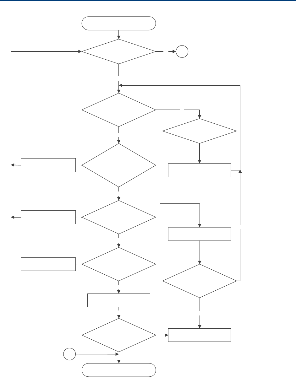
Chapter 11: Troubleshooting Power-up troubleshooting
Page 11-14
Power-up troubleshooting
ModuledoesnotpowerON
Isthe
LEDalwaysred?
IsthereACpower
goingtothesupply?
No
SwitchONACmainspower
Testca ble,useknown
goodcable.Couldtheradiobe
indefaultmode
Yes
Yes
Testcable?
No
Isca blelength<300meters?
Yes
Connecttoaknownpower
supply
Isthemodule’s
redLEDON ?
Yes
Yes
ModuleispoweredON
Yes
Ethernetcable
repaired
ContactCambiumSupportfor
RMA
No
IsModule’spower
LEDON?
No
A
Yes
Cablewireandpinout
corrected
Cablelengthwithin
300meters
Yes
No
No
A
Connecttoknowngood
module
Ismodulegetting
poweredON?
No
Yes

Chapter 11: Troubleshooting Registration and connectivity troubleshooting
Page 11-15
Registration and connectivity troubleshooting
SM/BMS Registration
If no SMs are registered to this AP, then the Session Status tab displays the simple message No
sessions. In this case, try the following steps.
1 More finely aim the SM or SMs toward the AP.
2 Recheck the Session Status tab of the AP for the presence of LUIDs.
3 If still no LUIDs are reported on the Session Status tab, click the Configuration
button on the left side of the Home page.
RESULT: The AP responds by opening the AP Configuration page.
4 Click the Radio tab.
5 Find the Color Code parameter and note the setting.
6 In the same sequence as you did for the AP directly under Configuring Link for Test
on Page 5-16, connect the SM to a computing device and to power.
7 On the left side of the SM Home page, click the Configuration button.
RESULT: The Configuration page of the SM opens.
8 Click the Radio tab.
9 If the transmit frequency of the AP is not selected in the Custom Radio Frequency
Scan Selection List parameter, select the frequency that matches.
10 If the Color Code parameter on this page is not identical to the Color Code
parameter you noted from the AP, change one of them so that they match.
11 At the bottom of the Radio tab for the SM, click the Save Changes button.
12 Click the Reboot button.
13 Allow several minutes for the SM to reboot and register to the AP.
14 Return to the computing device that is connected to the AP.
15 Recheck the Session Status tab of the AP for the presence of LUIDs.
Page I
Appendix A - 450m Reference Information
Specifications
Please see the Spec Sheets listed on the Cambium Networks website for the most up-to-
date 450m Series cnMedusa AP specifications:
http://www.cambiumnetworks.com/resources/pmp-450m/
450m overload
The 450m Series AP is designed to handle high load in terms of high throughput and
high PPS. In terms of throughput, 450m is designed to achieve 3x or more
throughput improvement over 450 and 450i Series products. In terms of packets per
second (PPS), 450m is designed to handle up to 100k PPS.
Overload occurs when the offered load exceeds the above limits. When overload
occurs, 450m will start discarding packets and TCP throughput will degrade due to
packet loss. The 450 family of products have a set of overload statistics that can be
used to monitor overload conditions (Statistics >Overload tab).
The above statistics shall be monitored over time for overload conditions over
consecutive periods. Refer to the 450 Platform User’s Guide Chapter 9 section
Interpreting Overload statistics for description of those statistics.
Chapter 11: Troubleshooting Registration and connectivity troubleshooting
Page II
It’s worth noting that Frame Utilization statistics (Statistics >Frame Utilization tab:
Frame Utilization: Downlink and Uplink) are not necessarily indicative of overload
condition. They show how much the TDD frame is utilized. High frame utilization
depends on:
1) high traffic during busy periods: those statistics will be close to 100% and
almost all slots will be utilized. In this case if the Overload statistics show that
packets are discarded then this is an indication of overload condition.
2) high percentage of VCs with low modulation with moderate traffic. Those VCs
will require more slots to service them (due to low modulation) and the frame
utilization will be high. In this case the TDD frame is fully utilized but the
system is at low capacity and is not in an overload condition.
450m has higher PPS than 450 and 450i and supports higher throughput through spatial
multiplexing, therefore when a 450m replaces an overloaded 450 or 450i AP the 450m will
not be overloaded under the same conditions but the frame utilization may still show close
to 100%; this should not alarm the customer. The overload statistics shall be monitored on
450m to see if it is overloaded or not.

Chapter 11: Troubleshooting Registration and connectivity troubleshooting
Page III
Glossary
Term Definition
10Base-T Technology in Ethernet communications that can deliver 10 Mb of
data across 328 feet (100 meters) of CAT 5 cable.
169.254.0.0 Gateway IP address default in Cambium fixed wireless broadband IP
network modules.
169.254.1.1 IP address default in Cambium fixed wireless broadband IP network
modules.
255.255.0.0 Subnet mask default in Cambium fixed wireless broadband IP
network modules and in Microsoft and Apple operating systems.
802.3 An IEEE standard that defines the contents of frames that are
transferred through Ethernet connections. Each of these frames
contains a preamble, the address to which the frame is sent, the
address that sends the frame, the length of the data to expect, the
data, and a checksum to validate that no contents were lost.
Access Point Cluster Two to six Access Point Modules that together distribute network or
Internet services to a community of subscribers. Each Access Point
Module covers a 60° or 90° sector. This cluster covers as much as
360°. Also known as AP cluster.
Access Point Module Also known as AP. One module that distributes network or Internet
services in a 60° or 90° sector.
ACT/4 Second-from-left LED in the module. In the operating mode, this
LED is lit when data activity is present on the Ethernet link.
Address Resolution
Protocol
Protocol defined in RFC 826 to allow a network element to correlate
a host IP address to the Ethernet address of the host. See
http://www.faqs.org/rfcs/rfc826.html.
Aggregate Throughput The sum of the throughputs in the uplink and the downlink.
AP Access Point Module. One module that distributes network or
Internet services to subscriber modules.
ARP Address Resolution Protocol. A protocol defined in RFC 826 to allow
a network element to correlate a host IP address to the Ethernet
address of the host. See http://www.faqs.org/rfcs/rfc826.html.
APs MIB
Management Information Base file that defines objects that are
specific to the Access Point Module. See also Management
Information Base.

Chapter 11: Troubleshooting Registration and connectivity troubleshooting
Page IV
Term Definition
ASN.1 Abstract Syntax Notation One language. The format of the text files
that compose the Management Information Base.
Attenuation Reduction of signal strength caused by the travel from the
transmitter to the receiver, and caused by any object between. In
the absence of objects between, a signal that has a short
wavelength experiences a high degree of attenuation nevertheless.
BER Bit Error Rate. The ratio of incorrect data received to correct data
received.
BHM Backhaul Timing Master (BHM)- a module that is used in a point to
point link. This module controls the air protocol and configurations
for the link..
BHS Backhaul Timing Slave (BHS)- a module that is used in a point to
point link. This module accepts configuration and timing from the
master module.
Bit Error Rate Ratio of incorrect data received to correct data received.
Box MIB Management Information Base file that defines module-level
objects. See also Management Information Base.
Bridge Network element that uses the physical address (not the logical
address) of another to pass data. The bridge passes the data to
either the destination address, if found in the simple routing table,
or to all network segments other than the one that transmitted the
data. Modules are Layer 2 bridges except that, where NAT is
enabled for an SM, the SM is a Layer 3 switch. Compare to Switch
and Router, and see also NAT.
Buckets Theoretical data repositories that can be filled at preset rates or
emptied when preset conditions are experienced, such as when
data is transferred.
Burst Preset amount limit of data that may be continuously transferred.
CAT 5 Cable Cable that delivers Ethernet communications from module to
module. Later modules auto-sense whether this cable is wired in a
straight-through or crossover scheme.
CIR Committed Information Rate. For an SM or specified group of SMs,
a level of bandwidth that can be guaranteed to never fall below a
specified minimum (unless oversubscribed). In the Cambium
implementation, this is controlled by the Low Priority Uplink CIR,
Low Priority Downlink CIR, High Priority Uplink CIR, and High
Priority Downlink CIR parameters.

Chapter 11: Troubleshooting Registration and connectivity troubleshooting
Page V
Term Definition
Cluster Management
Module
Module that provides power, GPS timing, and networking
connections for an AP cluster. Also known as CMM4.
CMM Cluster Management Module. A module that provides power, GPS
timing, and networking connections for an Access Point cluster.
CodePoint See DiffServ.
Color Code Field Module parameter that identifies the other modules with which
communication is allowed. The range of valid values is 0 to 255.
Community String Field Control string that allows a network management station to access
MIB information about the module.
Connectorized The 450 Platform Family Connectorized Radio solution provide RF
port to connect external antenna. It gives flexibility to connect to a
variety of external antennas.
Country Code A parameter that offers multiple fixed selections, each of which
automatically implements frequency band range restrictions for the
selected country. Units shipped to countries other than the United
States must be configured with the corresponding Region Code and
Country Code to comply with local regulatory requirements.
CRCError Field This field displays how many CRC errors occurred on the Ethernet
controller.
Data Encryption Standard Over-the-air link option that uses secret 56-bit keys and 8 parity bits.
Data Encryption Standard (DES) performs a series of bit
permutations, substitutions, and recombination operations on
blocks of data.
Demilitarized Zone Internet Protocol area outside of a firewall. Defined in RFC 2647. See
http://www.faqs.org/rfcs/rfc2647.html.
DES Data Encryption Standard. An over-the-air link option that uses
secret 56-bit keys and 8 parity bits. DES performs a series of bit
permutations, substitutions, and recombination operations on
blocks of data.
DFS See Dynamic Frequency Selection
DHCP Dynamic Host Configuration Protocol, defined in RFC 2131. Protocol
that enables a device to be assigned a new IP address and TCP/IP
parameters, including a default gateway, whenever the device
reboots. Thus DHCP reduces configuration time, conserves IP
addresses, and allows modules to be moved to a different network
within the system. See http://www.faqs.org/rfcs/rfc2131.html. See
also Static IP Address Assignment.

Chapter 11: Troubleshooting Registration and connectivity troubleshooting
Page VI
Term Definition
DiffServ Differentiated Services, consistent with RFC 2474. A byte in the type
of service (TOS) field of packets whose values correlates to the
channel on which the packet should be sent. The value is a numeric
code point. Cambium modules map each of 64 code points to
values of 0 through 7. Three of these code points have fixed values,
and the remaining 61 are settable. Values of 0 through 3 map to the
low-priority channel; 4 through 7 to the high-priority channel. The
mappings are the same as 802.1p VLAN priorities. (However,
configuring DiffServ does not automatically enable the VLAN
feature.) Among the settable parameters, the values are set in the
AP for all downlinks within the sector and in the SM for each uplink.
DMZ Demilitarized Zone as defined in RFC 2647. An Internet Protocol area
outside of a firewall. See http://www.faqs.org/rfcs/rfc2647.html.
Dynamic Frequency
Selection
A requirement in certain countries and regions for systems to detect
interference from other systems, notably radar systems, and to
avoid co-channel operation with these systems.
Dynamic Host
Configuration Protocol
See DHCP.
Electronic Serial Number Hardware address that the factory assigns to the module for
identification in the Data Link layer interface of the Open Systems
Interconnection system. This address serves as an electronic serial
number. Same as MAC Address.
ESN Electronic Serial Number. The hardware address that the factory
assigns to the module for identification in the Data Link layer
interface of the Open Systems Interconnection system. This address
serves as an electronic serial number. Same as MAC Address.
Ethernet Protocol Any of several IEEE standards that define the contents of frames
that are transferred from one network element to another through
Ethernet connections.
ETSI European Telecommunications Standards Institute
Fade Margin The difference between strength of the received signal and the
strength that the receiver requires for maintaining a reliable link. A
higher fade margin is characteristic of a more reliable link. Standard
operating margin.
FCC Federal Communications Commission of the U.S.A.
Field-programmable Gate
Array
Array of logic, relational data, and wiring data that is factory
programmed and can be reprogrammed.

Chapter 11: Troubleshooting Registration and connectivity troubleshooting
Page VII
Term Definition
File Transfer Protocol Utility that transfers of files through TCP (Transport Control
Protocol) between computing devices that do not operate on the
same platform. Defined in RFC 959. See
http://www.faqs.org/rfcs/rfc959.html.
FPGA Field-programmable Gate Array. An array of logic, relational data,
and wiring data that is factory programmed and can be
reprogrammed.
Free Space Path Loss Signal attenuation that is naturally caused by atmospheric
conditions and by the distance between the antenna and the
receiver.
Fresnel Zone Space in which no object should exist that can attenuate, diffract, or
reflect a transmitted signal before the signal reaches the target
receiver.
FTP File Transfer Protocol, defined in RFC 959. Utility that transfers of
files through TCP (Transport Control Protocol) between computing
devices that do not operate on the same platform. See
http://www.faqs.org/rfcs/rfc959.html.
Global Positioning
System
Network of satellites that provides absolute time to networks on
earth, which use the time signal to synchronize transmission and
reception cycles (to avoid interference) and to provide reference for
troubleshooting activities.
GPS Global Positioning System. A network of satellites that provides
absolute time to networks on earth, which use the time signal to
synchronize transmission and reception cycles (to avoid
interference) and to provide reference for troubleshooting activities.
GPS/3 Third-from-left LED in the module. In the operating mode for an
Access Point Module, this LED is continuously lit as the module
receives sync pulse. In the operating mode for a Subscriber, this
LED flashes on and off to indicate that the module is not registered.
GUI Graphical user interface.
High-priority Channel Channel that supports low-latency traffic (such as Voice over IP)
over low-latency traffic (such as standard web traffic and file
downloads). To recognize the latency tolerance of traffic, this
channel reads the IPv4 Type of Service DiffServ Control Point
(DSCP) bits. Enabling the high-priority channel reduces the
maximum number of SMs that can be served in the sector.
HTTP Hypertext Transfer Protocol, used to make the Internet resources
available on the World Wide Web. Defined in RFC 2068. See
http://www.faqs.org/rfcs/rfc2068.html.

Chapter 11: Troubleshooting Registration and connectivity troubleshooting
Page VIII
Term Definition
HTTPS Hypertext Transfer Protocol Secure (HTTPS)
ICMP Internet Control Message Protocols defined in RFC 792, used to
identify Internet Protocol (IP)-level problems and to allow IP links to
be tested. See http://www.faqs.org/rfcs/rfc792.html.
Integrated The 450 Platform Family Integrated Radio solution provides
integrated antenna..
IP Internet Protocol defined in RFC 791. The Network Layer in the
TCP/IP protocol stack. This protocol is applied to addressing,
routing, and delivering, and re-assembling data packets into the
Data Link layer of the protocol stack. See
http://www.faqs.org/rfcs/rfc791.html.
IP Address 32-bit binary number that identifies a network element by both
network and host. See also Subnet Mask.
IPv4 Traditional version of Internet Protocol, which defines 32-bit fields
for data transmission.
ISM Industrial, Scientific, and Medical Equipment radio frequency band,
in the 900-MHz, 2.4-GHz, and 5.8-GHz ranges.
L2TP over IPSec Level 2 Tunneling Protocol over IP Security. One of several virtual
private network (VPN) implementation schemes. Regardless of
whether Subscriber Modules have the Network Address Translation
feature (NAT) enabled, they support VPNs that are based on this
protocol.
Late Collision Field This field displays how many late collisions occurred on the
Ethernet controller. A normal collision occurs during the first 512
bits of the frame transmission. A collision that occurs after the first
512 bits is considered a late collision. A late collision is a serious
network problem because the frame being transmitted is discarded.
A late collision is most commonly caused by a mismatch between
duplex configurations at the ends of a link segment.
Line of Sight Wireless path (not simply visual path) direct from module to
module. The path that results provides both ideal aim and an ideal
Fresnel zone.
LNK/5 Furthest left LED in the module. In the operating mode, this LED is
continuously lit when the Ethernet link is present. In the aiming
mode for a Subscriber Module, this LED is part of a bar graph that
indicates the quality of the RF link.
Logical Unit ID Final octet of the 4-octet IP address of the module.

Chapter 11: Troubleshooting Registration and connectivity troubleshooting
Page IX
Term Definition
LOS Line of sight. The wireless path (not simply visual path) direct from
module to module. The path that results provides both ideal aim
and an ideal Fresnel zone.
LUID Logical Unit ID. The final octet of the 4-octet IP address of the
module.
MAC Address Media Access Control address. The hardware address that the
factory assigns to the module for identification in the Data Link layer
interface of the Open Systems Interconnection system. This address
serves as an electronic serial number.
Management Information
Base
Space that allows a program (agent) in the network to relay
information to a network monitor about the status of defined
variables (objects).
Maximum Information
Rate (MIR)
The cap applied to the bandwidth of an SM or specified group of
SMs. In the Cambium implementation, this is controlled by the
Sustained Uplink Data Rate, Uplink Burst Allocation, Sustained
Downlink Data Rate, and Downlink Burst Allocation parameters.
MIB Management Information Base. Space that allows a program
(agent) in the network to relay information to a network monitor
about the status of defined variables (objects).
MIR See Maximum Information Rate.
MU-MIMO Multi User- Multiple Input Multiple Output
NAT Network Address Translation defined in RFC 1631. A scheme that
isolates Subscriber Modules from the Internet. See
http://www.faqs.org/rfcs/rfc1631.html.
NEC National Electrical Code. The set of national wiring standards that
are enforced in the U.S.A.
NetBIOS Protocol defined in RFC 1001 and RFC 1002 to support an
applications programming interface in TCP/IP. This interface allows
a computer to transmit and receive data with another host computer
on the network. RFC 1001 defines the concepts and methods. RFC
1002 defines the detailed specifications. See
http://www.faqs.org/rfcs/rfc1001.html and
http://www.faqs.org/rfcs/rfc1002.html.
Network Address
Translation
Scheme that defines the Access Point Module as a proxy server to
isolate registered Subscriber Modules from the Internet. Defined in
RFC 1631. See http://www.faqs.org/rfcs/rfc1631.html.
Network Management
Station
See NMS.

Chapter 11: Troubleshooting Registration and connectivity troubleshooting
Page X
Term Definition
NMS Network Management Station. A monitor device that uses Simple
Network Management Protocol (SNMP) to control, gather, and
report information about predefined network variables (objects).
See also Simple Network Management Protocol.
Default Mode Device that enables the operator to regain control of a module that
has been locked by the No Remote Access feature, the 802.3 Link
Disable feature, or a password or IP address that cannot be recalled.
This device can be either fabricated on site or ordered.
PMP See Point-to-Multipoint Protocol.
Point-to-Multipoint
Protocol
Defined in RFC 2178, which specifies that data that originates from a
central network element can be received by all other network
elements, but data that originates from a non-central network
element can be received by only the central network element. See
http://www.faqs.org/rfcs/rfc2178.html. Also referenced as PMP.
PPPoE Point to Point Protocol over Ethernet. Supported on SMs for
operators who use PPPoE in other parts of their network operators
who want to deploy PPPoE to realize per-subscriber authentication,
metrics, and usage control.
PPS Packet Per Second
PPTP Point to Point Tunneling Protocol. One of several virtual private
network implementations. Regardless of whether the Network
Address Translation (NAT) feature enabled, Subscriber Modules
support VPNs that are based on this protocol.
Protective Earth Connection to earth (which has a charge of 0 volts). Also known as
ground.
Proxy Server Network computer that isolates another from the Internet. The
proxy server communicates for the other computer, and sends
replies to only the appropriate computer, which has an IP address
that is not unique or not registered.
PTP A Point-to-Point connection refers to a communications connection
between two nodes or endpoints.
Radio Signal Strength
Indicator
Relative measure of the strength of a received signal. An acceptable
link displays a Radio Signal Strength Indicator (RSSI) value of
greater than 700.

Chapter 11: Troubleshooting Registration and connectivity troubleshooting
Page XI
Term Definition
Reflection Change of direction and reduction of amplitude of a signal that
encounters an object larger than the wavelength. Reflection may
cause an additional copy of the wavelength to arrive after the
original, unobstructed wavelength arrives. This causes partial
cancellation of the signal and may render the link unacceptable.
However, in some instances where the direct signal cannot be
received, the reflected copy may be received and render an
otherwise unacceptable link acceptable.
Region Code A parameter that offers multiple fixed selections, each of which
automatically implements frequency band range restrictions for the
selected region. Units shipped to regions other than the United
States must be configured with the corresponding Region Code to
comply with local regulatory requirements.
RF Radio frequency. How many times each second a cycle in the
antenna occurs, from positive to negative and back to positive
amplitude.
RJ-12 Standard cable that is typically used for telephone line or modem
connection.
RJ-45 Standard cable that is typically used for Ethernet connection. This
cable may be wired as straight-through or as crossover. Later
modules auto-sense whether the cable is straight-through or
crossover.
Router Network element that uses the logical (IP) address of another to
pass data to only the intended recipient. Compare to Switch and
Bridge.
RSSI Radio Signal Strength Indicator. A relative measure of the strength
of a received signal. An acceptable link displays an RSSI value of
greater than 700.
Self-interference Interference with a module from another module in the same
network.
SFP Small Form-factor Pluggable
Simple Network
Management Protocol
Standard that is used for communications between a program
(agent) in the network and a network management station
(monitor). Defined in RFC 1157. See
http://www.faqs.org/rfcs/rfc1157.html.
SM Customer premises equipment (CPE) device that extends network or
Internet services by communication with an Access Point Module or
an Access Point cluster.
SNMP See Simple Network Management Protocol, defined in RFC 1157.

Chapter 11: Troubleshooting Registration and connectivity troubleshooting
Page XII
Term Definition
SNMPv3 SNMP version 3
SNMP Trap Capture of information that informs the network monitor through
Simple Network Management Protocol of a monitored occurrence in
the module.
Static IP Address
Assignment
Assignment of Internet Protocol address that can be changed only
manually. Thus static IP address assignment requires more
configuration time and consumes more of the available IP
addresses than DHCP address assignment does. RFC 2050 provides
guidelines for the static allocation of IP addresses. See
http://www.faqs.org/rfcs/rfc2050.html. See also DHCP.
Subnet Mask 32-bit binary number that filters an IP address to reveal what part
identifies the network and what part identifies the host. The number
of subnet mask bits that are set to 1 indicates how many leading
bits of the IP address identify the network. The number of subnet
mask bits that are set 0 indicate how many trailing bits of the IP
address identify the host.
Subscriber Module Customer premises equipment (CPE) device that extends network or
Internet services by communication with an Access Point Module or
an Access Point cluster.
Sustained Data Rate Preset rate limit of data transfer.
Switch Network element that uses the port that is associated with the
physical address of another to pass data to only the intended
recipient. Compare to Bridge and Router.
Sync GPS (Global Positioning System) absolute time, which is passed
from one module to another. Sync enables timing that prevents
modules from transmitting or receiving interference. Sync also
provides correlative time stamps for troubleshooting efforts.
TCP Alternatively known as Transmission Control Protocol or Transport
Control Protocol. The Transport Layer in the TCP/IP protocol stack.
This protocol is applied to assure that data packets arrive at the
target network element and to control the flow of data through the
Internet. Defined in RFC 793. See
http://www.faqs.org/rfcs/rfc793.html.
TDD Time Division Duplexing. Synchronized data transmission with
some time slots allocated to devices transmitting on the uplink and
some to the device transmitting on the downlink.
Chapter 11: Troubleshooting Registration and connectivity troubleshooting
Page XIII
Term Definition
telnet Utility that allows a client computer to update a server. A firewall
can prevent the use of the telnet utility to breach the security of the
server. See http://www.faqs.org/rfcs/rfc818.html,
http://www.faqs.org/rfcs/rfc854.html and
http://www.faqs.org/rfcs/rfc855.html.
Tokens Theoretical amounts of data. See also Buckets.
TxUnderrun Field This field displays how many transmission-underrun errors
occurred on the Ethernet controller.
UDP User Datagram Protocol. A set of Network, Transport, and Session
Layer protocols that RFC 768 defines. These protocols include
checksum and address information but does not retransmit data or
process any errors. See http://www.faqs.org/rfcs/rfc768.html.
udp User-defined type of port.
U-NII Unlicensed National Information Infrastructure radio frequency
band, in the 5.1GHz through 5.8 GHz ranges.
VID VLAN identifier. See also VLAN.
VLAN Virtual local area network. An association of devices through
software that contains broadcast traffic, as routers would, but in the
switch-level protocol.
VPN Virtual private network for communication over a public network.
One typical use is to connect remote employees, who are at home
or in a different city, to their corporate network over the Internet.
Any of several VPN implementation schemes is possible. SMs
support L2TP over IPSec (Level 2 Tunneling Protocol over IP
Security) VPNs and PPTP (Point to Point Tunneling Protocol) VPNs,
regardless of whether the Network Address Translation (NAT)
feature enabled.