Cambium Networks 50450I Wireless Ethernet Bridge, Dual Channel OFDM MIMO Combination Access Point, Subscriber Station and Point to Point Equipment User Manual PMP PTP 450i Series User Guide
Cambium Networks Limited Wireless Ethernet Bridge, Dual Channel OFDM MIMO Combination Access Point, Subscriber Station and Point to Point Equipment PMP PTP 450i Series User Guide
Contents
- 1. Installation Guide
- 2. User Guide Part 1
- 3. User Guide Part 2
- 4. User Guide Part 3
- 5. User Guide Part 4
- 6. User Guide Part 5
- 7. User Guide Part 6
- 8. User Guide Part 7
- 9. Exhibit D Users Manual per 2 1033 b3
- 10. User Manual - Part 1
- 11. User Manual - Part 2
- 12. User Manual - Part 3
- 13. User Manual - Part 4
- 14. Users Manual - Part 5
- 15. Users Manual - Part 6
- 16. User Manual
User Guide Part 5

Chapter 9: Operation System information
Page 9-12
Transmit Power This field lists the current combined transmit power level, in dBm.
Signal to Noise Ratio This field lists the current signal-to-noise level, an indication of the
separation of the received power level vs. noise floor.
Beacons Displays a count of beacons received by the BHM in percentage. This
value must be typically between 99-100%. If lower than 99%, it indicates
a problematic link. This statistic is updated every 16 seconds.
Air Delay This field displays the distance in feet between this BHS and the BHM.
To derive the distance in meters, multiply the value of this parameter by
0.3048. Distances reported as less than 200 feet (61 meters) are
unreliable.
Data Slots Down This field lists the number of slots used for downlink data transmission.
Data Slots Up This field lists the number of slots used for uplink data transmission.
Regional Code
A parameter that offers multiple fixed selections, each of which
automatically implements frequency band range restrictions for the
selected region. Units shipped to regions other than the United States
must be configured with the corresponding Country Code to comply
with local regulatory requirements.
Site Name This field indicates the name of the physical module. Assign or change
this name in the
Configuration > SNMP
page. This information is also set
into the sysName SNMP MIB-II object and can be polled by an SNMP
management server.
Chapter 9: Operation System information
Page 9-13
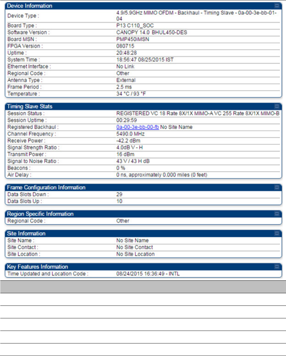
General Status page of BHS
The BHS’s
General Status
page is explained in Table 141.
Table 142
General Status page attributes - BHS
Attribute
Meaning
Device Type See Table 141 on page 9-13.
Board Type See Table 141 on page 9-13.
Software Version See Table 141 on page 9-13.
Board MSN See Table 141 on page 9-13.
FPGA Version See Table 141 on page 9-13.

Chapter 9: Operation System information
Page 9-14
Uptime See Table 141 on page 9-13.
System Time See Table 141 on page 9-13.
Ethernet Interface See Table 141 on page 9-13.
Antenna Type See Table 141 on page 9-13.
Temperature See Table 141 on page 9-13.
Session Status See Table 141 on page 9-13.
Session Uptime See Table 141 on page 9-13.
Registered Backhaul See Table 141 on page 9-13.
Channel Frequency See Table 141 on page 9-13.
Receive Power See Table 141 on page 9-13.
Signal Strength
Ratio
See Table 141 on page 9-13.
Transmit Power See Table 141 on page 9-13.
Signal to Noise Ratio See Table 141 on page 9-13.
Beacons See Table 141 on page 9-13.
Air Delay See Table 141 on page 9-13.
Data Slots Down See Table 141 on page 9-13.
Data Slots Up See Table 141 on page 9-13.
Regional Code See Table 141 on page 9-13.
Site Name See Table 141 on page 9-13.
Site Contact See Table 141 on page 9-13.
Site Location See Table 141 on page 9-13.
Time Updated and
Location Code
See Table 141 on page 9-13.
Viewing Session Status
The
Session Status
page in the Home page provides information about each SM or BHS that has
registered to the AP or BHM. This information is useful for managing and troubleshooting a
system. This page also includes the current active values on each SM or BHS for MIR and VLAN, as
well as the source of these values, representing the SM/BHS itself, Authentication Server, or the
Authentication Server and SM/BHS.
Chapter 9: Operation System information
Page 9-15
Note
In order for accurate power level readings to be displayed, traffic must be present on
the radio link.
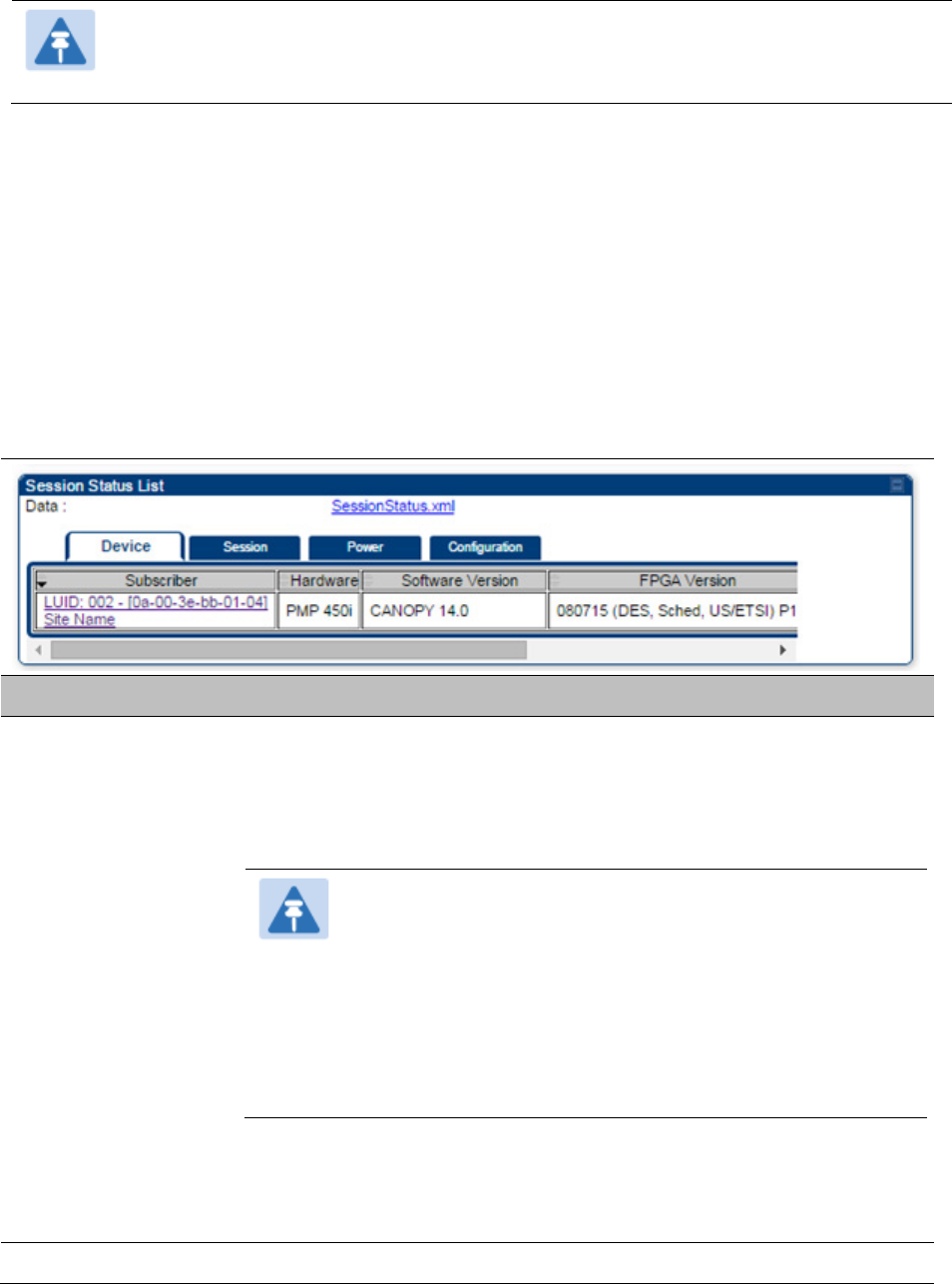
The Session Status List has four tab: Device, Session, Power and Configuration.
The SessionStatus.xml hyper link allows user to export session status page from web
management interface of AP or BHM. The session status page will be exported in xml file.
Device tab
The Device tab provides information on the Subscriber’s LUID and MAC, Hardware, Software,
FPGA versions and the state of the SM/BHS (Registered and/or encrypted).
Table 143
Device tab attributes
Attribute
Meaning
Subscriber This field displays the LUID (logical unit ID), MAC address and Site Name
of the SM/BHS. As each SM or BHS registers to the AP/BHM, the system
assigns an LUID of 2 or a higher unique number to the SM/BHS. If a
SM/BHS loses registration with the AP/BHS and then regains
registration, the SM/BHS will retain the same LUID.
Note
The LUID associated is lost when a power cycle of the
AP/BHM occurs.
Both the LUID and the MAC are hot links to open the
interface to the SM/BHS. In some instances, depending on
network activity and network design, this route to the
interface yields a blank web page. If this occurs, refresh
your browser view.
Site Name indicates the name of the SM/BHS. Change this name on the
Configuration web page of the SM/BHS. This information is also set into
the sysName SNMP MIB-II object and can be polled by an SNMP
management server.
Hardware This field displays the SMs or BHS hardware type.
Chapter 9: Operation System information
Page 9-16
Software Version This field displays the software release that operates on the SM/BHS, the
release date and time of the software.
FPGA Version This field displays the version of FPGA that runs on the SM/BHS
State
This field displays the current status of the SM/BHS as either
IN SESSION
to indicate that the SM/BHS is currently registered to the
AP/BHM.
IDLE
to indicate that the SM/BHS was registered to the AP/BHM at one
time, but now is not.
This field also indicates whether the encryption scheme in the module is
enabled.
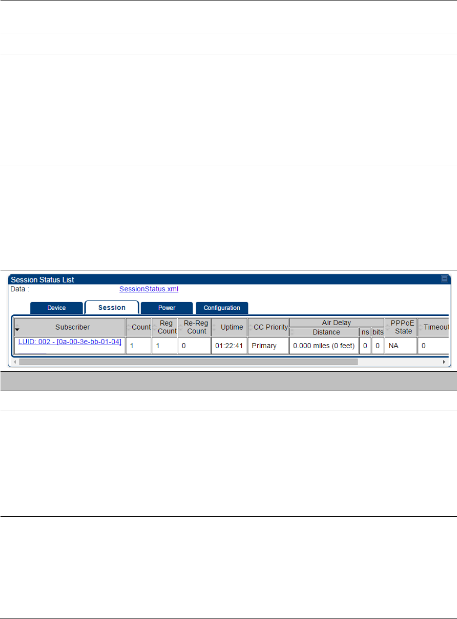
Session tab
The Session tab provides information on the SMs or BHS Session Count, Reg Count, Re-Reg
Count, Uptime, Air delay, PPPoE State and Timeouts.
Table 144
Session tab attributes
Attribute
Meaning
Subscriber See Table 142 on page 9-15.
Count This field displays how many sessions the SM/BHS has had with the
AP/BHM. Typically, this is the sum of Reg Count and Re-Reg Count.
However, the result of internal calculation may display here as a value
that slightly differs from the sum.
If the number of sessions is significantly greater than the number for
other SMs or BHS, then this may indicate a link problem or an
interference problem.
Reg Count When a SM/BHS makes a registration request, the AP/BHM checks its
local data to see whether it considers the SM/BHS to be already
registered. If the AP/BHM concludes that the SM/BHS is not, then the
request increments the value of this field.
If the number of sessions is significantly greater than the number for
other SMs or BHS, then this may indicate a link problem (check
mounting, alignment, receive power levels) or an interference problem
Chapter 9: Operation System information
Page 9-17
(conduct a spectrum scan).
Re-Reg Count
When a SM/BHS makes a registration request, the AP/BHM checks its
local data to see whether it considers the SM/BHS to be already
registered. If the AP/BHM concludes that the SM/BHS is not, then the
request increments the value of this field. Typically, a Re-Reg is the case
where both:
• SM/BHS attempts to reregister for having lost communication with
the AP/BHM.
• AP/BHM has not yet observed the link to the SM/BHS as being down.
If the number of sessions is significantly greater than the number for
other SMs or BHS, then this may indicate a link problem (check
mounting, alignment, receive power levels) or an interference problem
(conduct a spectrum scan).
Uptime Once a SM/BHS successfully registers to an AP/BHM, this timer is
started. If a session drops or is interrupted, this timer is reactivated once
re-registration is complete.
AirDelay This field displays the distance of the SM/BHS from the AP/BHM in
meters, nanoseconds and bits. At close distances, the value in this field
is unreliable.
PPPoE state This field displays the current PPPoE state (whether configured) of the
SM/BHS.
Timeout This field displays the timeout in seconds for management sessions via
HTTP, ftp access to the SM/BHS. 0 indicates that no limit is imposed.
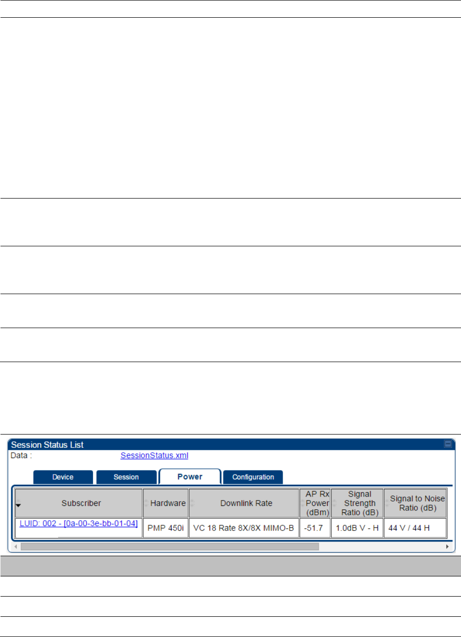
Power tab
Table 145
Power tab attributes
Attribute
Meaning
Subscriber See Table 142 on page 9-15.
Hardware This field displays the SMs or BHS hardware type.
Rate This field displays whether the high-priority channel is enabled in the
Chapter 9: Operation System information
Page 9-18
SM/BHS and the status of rate adapt. For example, if “8X/4X” is listed,
the radio is capable of operating at 8X but is currently operating at 4X,
due to RF conditions.
This field also states whether it is MIMO-A or MIMO-B radio e.g. “8X/8X
MIMO-B” indicates MIMO-B and “8X/4X MIMO-A” indicates MIMO-A.
AP Receive Power
Level
This field indicates the AP’s or BHM’s combined receive power level for
the listed SM/BHS.
Signal Strength
Ratio
This field displays the ratio of the Vertical path received signal power to
the Horizontal path received signal power. This ratio can be useful for
determining multipathing conditions (high vertical to horizontal ratio).
Signal to Noise Ratio This field lists the current signal-to-noise level, an indication of the
separation of the received power level vs. noise floor.
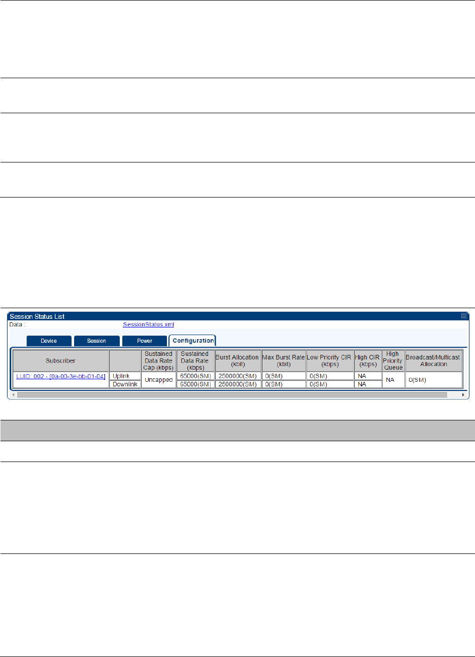
Configuration tab
The
Configuration
tab provides information on the SMs or BHS Uplink or Downlink (UL/DL)
Sustained Data Rate, UL/DL Burst Allocation, UL/DL Burst Rate, UL/DL Low Priority CIR, UL/DL High
CIR, UL/DL High Priority Queue Information and the UL/DL Broadcast or Multicast Allocation. This
data is refreshed based on the Web Page Auto Update setting on the AP’s or BHS’s General
Configuration page.
Table 146
Configuration tab attributes
Attribute
Meaning
Subscriber See Table 142 on page 9-15.
Sustained Data Rate This field displays the CIR value in kbps that is currently in effect for the
SM/BHS in both the Uplink and Downlink directior. In the Uplink, this is
the specified rate at which each SM/BHS registered to this AP/BHM is
replenished with credits for transmission. In the Downlink, this is the
specified rate at which the AP/BHM must be replenished with credits
(tokens) for transmission to each of the SMs or BHS in its sector.
Burst Allocation This field displays the Burst Allocation value that is currently in effect for
the SM/BHS in both the Uplink and Downlink direction. In the Uplink, this
is the specified maximum amount of data that each SM/BHS is allowed
to transmit before being recharged at the
Sustained Data Rate (Uplink)
with credits to transmit more. In the Downlink, this is the maximum
amount of data to allow the AP/BHM to transmit to any registered
SM/BHS before the AP/BHM is replenished with transmission credits at
Chapter 9: Operation System information
Page 9-19
the
Sustained Data Rate (Downlink)
.
Max Burst Rate The data rate at which a SM/BHS is allowed to burst (until burst
allocation limit is reached) before being recharged at the
Sustained Data
Rate (Uplink and Downlink individually)
with credits to transit more.
When set to 0 (default), the burst rate is unlimited.
Low Priority CIR This field indicates the minimum rate at which low priority traffic is sent
over the uplink and downlink (unless CIR is oversubscribed or RF link
quality is degraded).
High CIR This field indicates the minimum rate at which high priority traffic is sent
over the uplink and downlink (unless CIR is oversubscribed or RF link
quality is degraded).
High Priority Queue Not applicable for PMP/PTP 450i products.
Broadcast/Multicast
Allocation
This field displays the data rate at which Broadcast and Multicast traffic
is sent via the radio link.
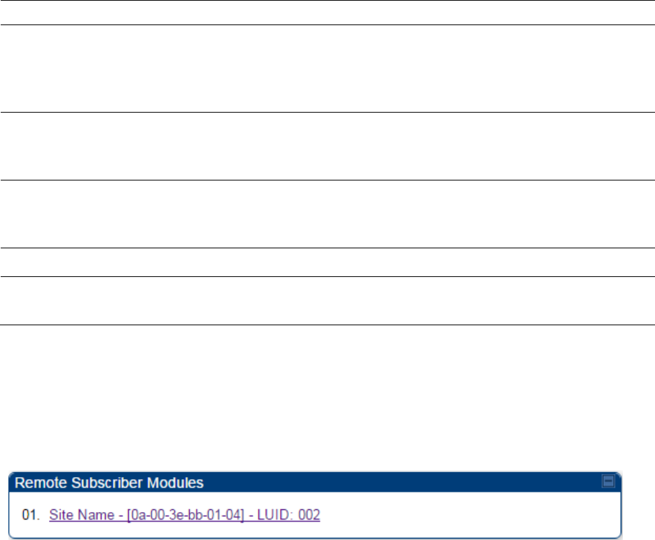
Viewing Remote Subscribers
This page allows to view the web pages of registered SMs ro BHS over the RF link. To view the
pages for a selected SM/BHS, click its link. The
General Status
page of the SM opens.
Figure 95
Remote Subscribers page - AP
Interpreting messages in the Event Log
Each line in the Event Log of a module Home page begins with a time and date stamp. However,
some of these lines wrap as a combined result of window width, browser preferences and line
length. You may find this tab easiest to use if you expand the window till all lines are shown
beginning with time and date stamp.
Time and Date Stamp
The time and date stamp reflect one of the following:
• GPS time and date directly or indirectly received from the CMM4.
• NTP time and date from a NTP server (CMM4 may serve as an NTP server)
• The running time and date that you have set in the Time & Date web page.
Chapter 9: Operation System information
Page 9-20
Note
In the Time & Date web page, if you have left any time field or date field unset and
clicked the
Set Time and Date
button, then the time and date default to
00:00:00 UT
: 01/01/00.
A reboot causes the preset time to pause or, in some cases, to run in reverse.
Additionally, a power cycle resets the running time and date to the default 00:00:00
UT : 01/01/00. Thus, whenever either a reboot or a power cycle has occurred,
must reset the time and date in the Time & Date web page of any module that is not
set to receive sync.
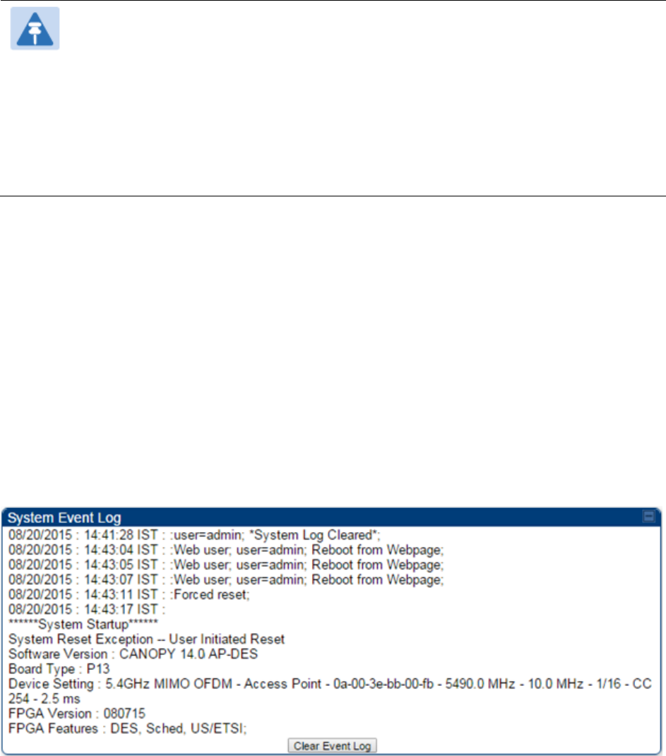
Event Log Data Collection
The collection of event data continues through reboots and power cycles. When the buffer
allowance for event log data is reached, the system adds new data into the log and discards an
identical amount of the oldest data.
Each line that contains the expression WatchDog flags an event that was both:
• considered by the system software to have been an exception
• recorded in the preceding line.
Conversely, a Fatal Error () message flags an event that is recorded in the next line. Some
exceptions and fatal errors may be significant and require either operator action or technical
support.
Figure 96
Event log data

Chapter 9: Operation System information
Page 9-21
Messages that Flag Abnormal Events
The messages listed below flag abnormal events and, case by case, may signal the need for
corrective action or technical support.
Table 147
Event Log messages for abnormal events
Event Message
Meaning
Expected LUID = 6
Actual LUID = 7
Something is interfering with the control messaging of the module. Also
ensure that you are using shielded cables to minimize interference.
Consider trying different frequency options to eliminate or reduce
interference.
FatalError() The event recorded on the line immediately beneath this message
triggered the Fatal Error ().
Loss of GPS Sync
Pulse Module has lost GPS sync signal.
Machine Check
Exception
This is a symptom of a possible hardware failure. If this is a recurring
message, begin the RMA process for the module.
RcvFrmNum =
0x00066d
ExpFrmNum =
0x000799
Something is interfering with the control messaging of the module. Also
ensure that you are using shielded cables to minimize interference.
Consider trying different frequency options to eliminate or reduce
interference.
System Reset
Exception -- External
Hard Reset
The unit lost power or was power cycled.
System Reset
Exception -- External
Hard Reset
WatchDog
The event recorded on the preceding line triggered this WatchDog
message.
Messages that Flag Normal Events
The messages listed below record normal events and typically do not signal a need for any
corrective action or technical support.
Table 148
Event Log messages for normal events
Event Message
Meaning
Acquired GPS Sync
Pulse. Module has acquired GPS sync signal.
FPGA Features Type of encryption.
FPGA Version FPGA (JBC) version in the module.
Chapter 9: Operation System information
Page 9-22
GPS Date/Time Set Module is now on GPS time.
Reboot from Webpage Module was rebooted from management interface.
Software Boot Version Boot version in the module.
Software Version The software release and authentication method for the unit.
System Log Cleared Event log was manually cleared.
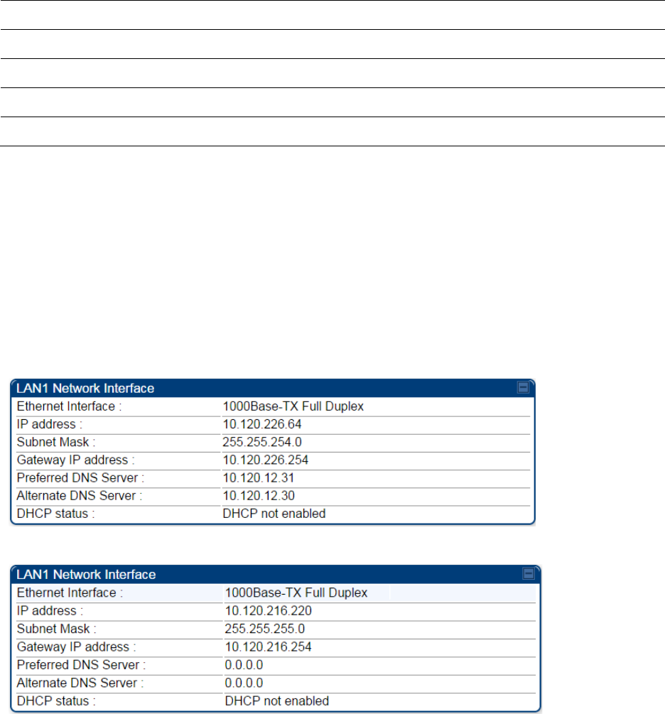
Viewing the Network Interface
In any module, the LAN1 Network Interface section of this tab displays the defined Internet
Protocol scheme for the Ethernet interface to the module. In SM/BHS devices, this page also
provides an RF Public Network Interface section, which displays the Internet Protocol scheme
defined for network access through the master device (AP/BHM).
Figure 97
Network Interface tab of the AP
Figure 98
Network Interface tab of the SM
Chapter 9: Operation System information
Page 9-23
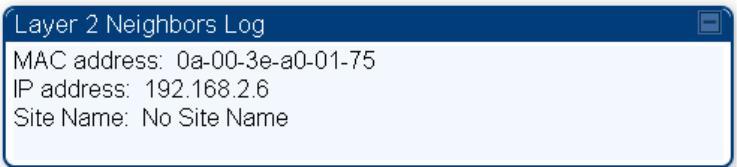
Viewing the Layer 2 Neighbors
In the Layer 2 Neighbors tab, a module reports any device from which it has received a message in
Link Layer Discovery Protocol within the previous two minutes. Given the frequency of LLDP
messaging, this means that the connected device will appear in this tab 30 seconds after it is
booted and remain until two minutes after its shutdown.
Figure 99
Layer 2 Neighbors page
Chapter 9: Operation System statistics
Page 9-24
System statistics
This section describes how to use the system statistics pages to manage the performance of the
PMP/PTP 450i link.
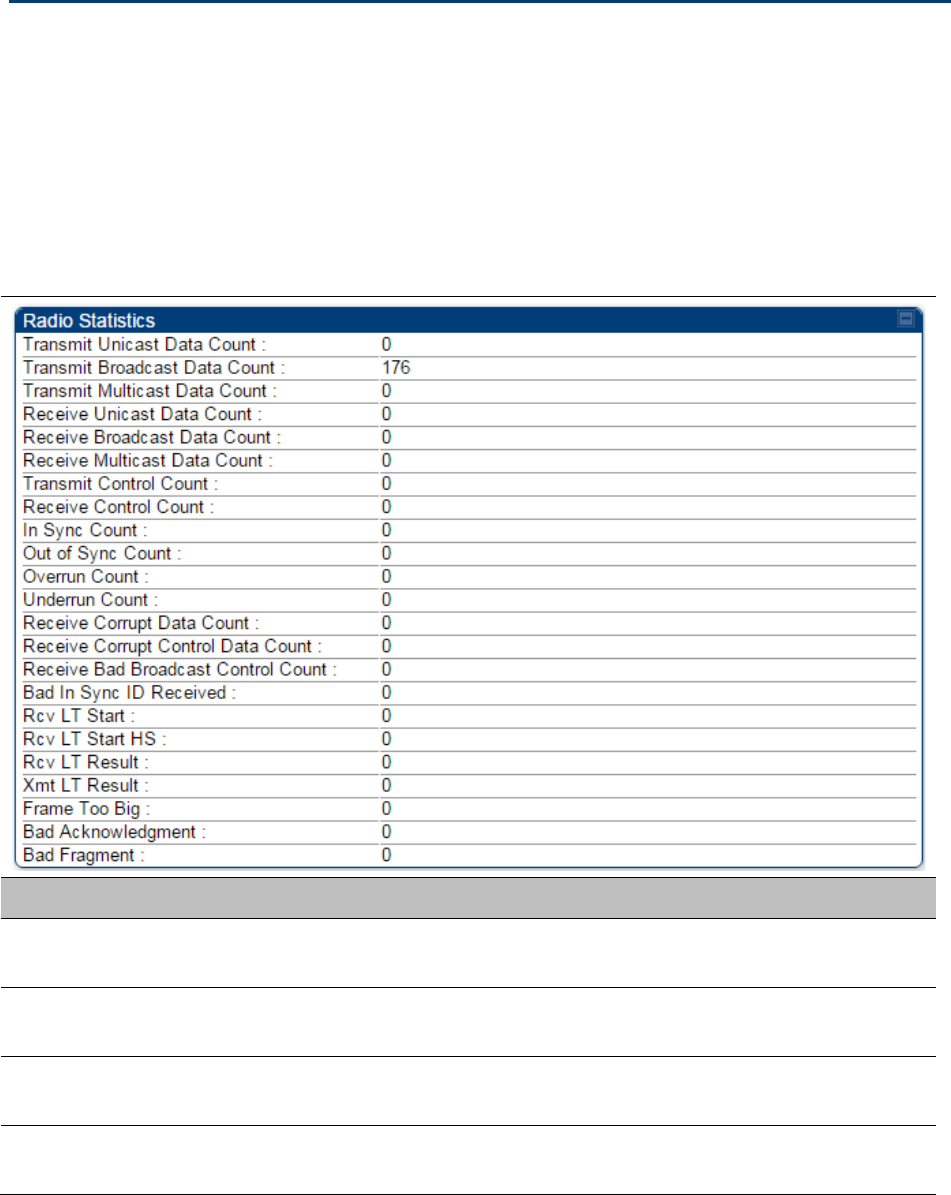
Viewing the Scheduler statistics
The
Statistics > Scheduler
page is applicable for all modules (AP/SM/BHM/BHS) and the
parameters are displayed as shown below:
Table 149
Scheduler tab attributes
Attribute
Meaning
Transmit Unicast
Data Count The total amount of unicast packets transmitted from the radio
Transmit Broadcast
Data Count The total amount of broadcast packets transmitted from the radio
Transmit Multicast
Data Count The total amount of multicast packets transmitted by the radio
Receive Unicast Data
Count The total amount of unicast packets received by the radio

Chapter 9: Operation System statistics
Page 9-25
Receive Broadcast
Data Count The total amount of broadcast packets received by the radio
Transmit Control
Count
The amount of radio control type messages transmitted (registration
requests and grants, power adjust, etc.).
Receive Control
Count
The amount of radio control type messages received (registration
requests and grants, power adjust, etc.).
In Sync Count Number of times the radio has acquired sync. In the case of an AP
generating sync this is when generated sync has been locked, or if GPS
synchronization is used it is number of times GPS sync acquired. For the
SM, it is the number of times the SM successfully obtained sync with an
AP.
Out of Sync Count Number of times the radio lost same sync lock.
Overrun Count Number of times FPGA frame has overrun its TX Frame
Underrun Count Number of times FPGAs TX Frame aborted prematurely.
Receive Corrupt Data
Count Number of times a corrupt fragment has been received at the FPGA.
Receive Bad
Broadcast Control
Count
Number of times the radio has received an invalid control message via
broadcast (SM only).
Bad In Sync ID
Received Currently unused
Rcv LT Start Number of Link Test Start messages received. A remote radio has
requested that this radio start a link test to it.
Rcv LT Start HS Number of Link Test Start Handshake messages received. This radio
requested that a remote radio start a link test and the remote radio has
sent a handshake back acknowledging the start.
Rcv LT Result This radio received Link Test results from the remote radio under
test. When this radio initiates a link test, the remote radio will send its
results to this radio for display.
Xmt LT Result This radio transmitted its link test results to the remote radio under
test. When the remote radio initiates a link test, this radio must send its
results to the remote radio for display there.
Frame Too Big This statistics indicates the number of packets received and processed
by the radios which were greater than max packet size 1700 bytes.
Bad
Acknowledgment
This statistics indicates the number of packets received as bad
acknowledgment. It is for engineering use only.
Bad Fragment This statistic indicates number of fragments tagged internally as bad. It
is for engineering use only.
Chapter 9: Operation System statistics
Page 9-26
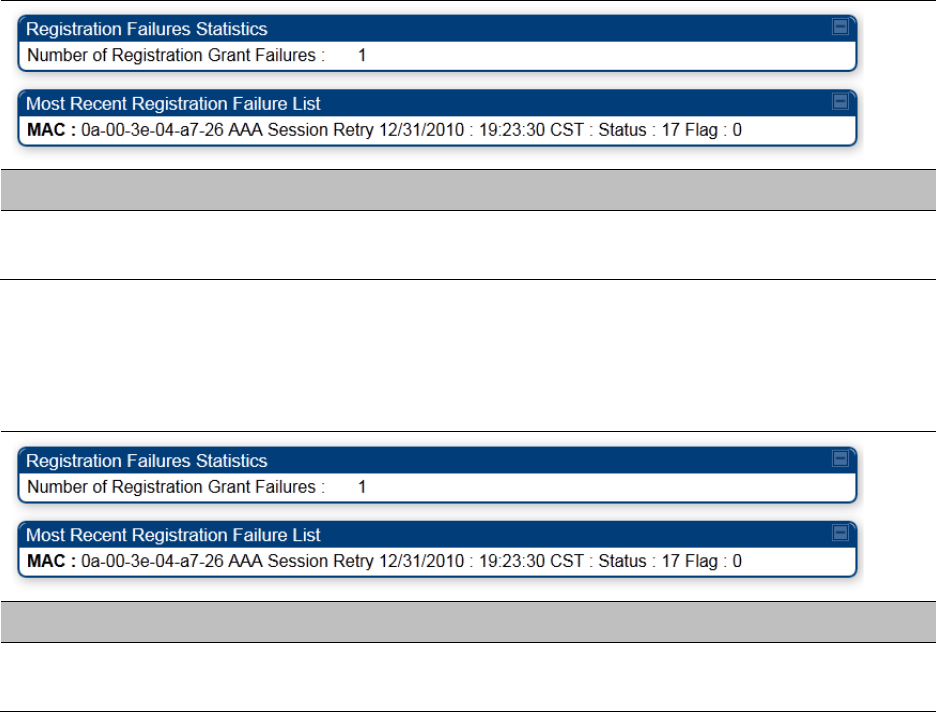
Viewing list of Registration Failures statistics
SM Registration Failures page of AP
The SM Registration Failures tab identifies SMs that have recently attempted and failed to register
to this AP. With its time stamps, these instances may suggest that a new or transient source of
interference exists.
Table 150
SM Registration Failures page attributes - AP
Attribute
Meaning
Status 17 Flag 0 No response was received from the AAA server and hence SM is trying
to send a session request again.
BHS Registration Failures page of BHM
Table 151
BHS Registration Failures page attributes - BHM
Attribute
Meaning
Status 17 Flag 0 No response was received from the AAA server and hence SM is trying
to send a session request again.
There is a list of flags from 0 to 20 as shown in Table 151 and the “Flags” can be ignored.
Chapter 9: Operation System statistics
Page 9-27
Table 152
Flags status
Flag
Meaning
Flag
Meaning
0 Normal 11 AP Lite Limit Reached
1 Out of Range 12 Only Ver 9.5+ Allowed
2 No Luids 13 Temporary Data VC for AAA
3 BH ReRange 14 AAA Authentication Failure
4 Auth Fail 15 Registration Grant Reject
5 Encrypt Fail 16 Blank
6 Power Adjust 17 AAA Session Retry
7 No VCs 18 AAA Reauth Failure
8 Reserve VC Fail 19 RegReq at zero power
9 Activate VC Fail 20 RegReq no time ref
10 Hi VC Setup Fail - -
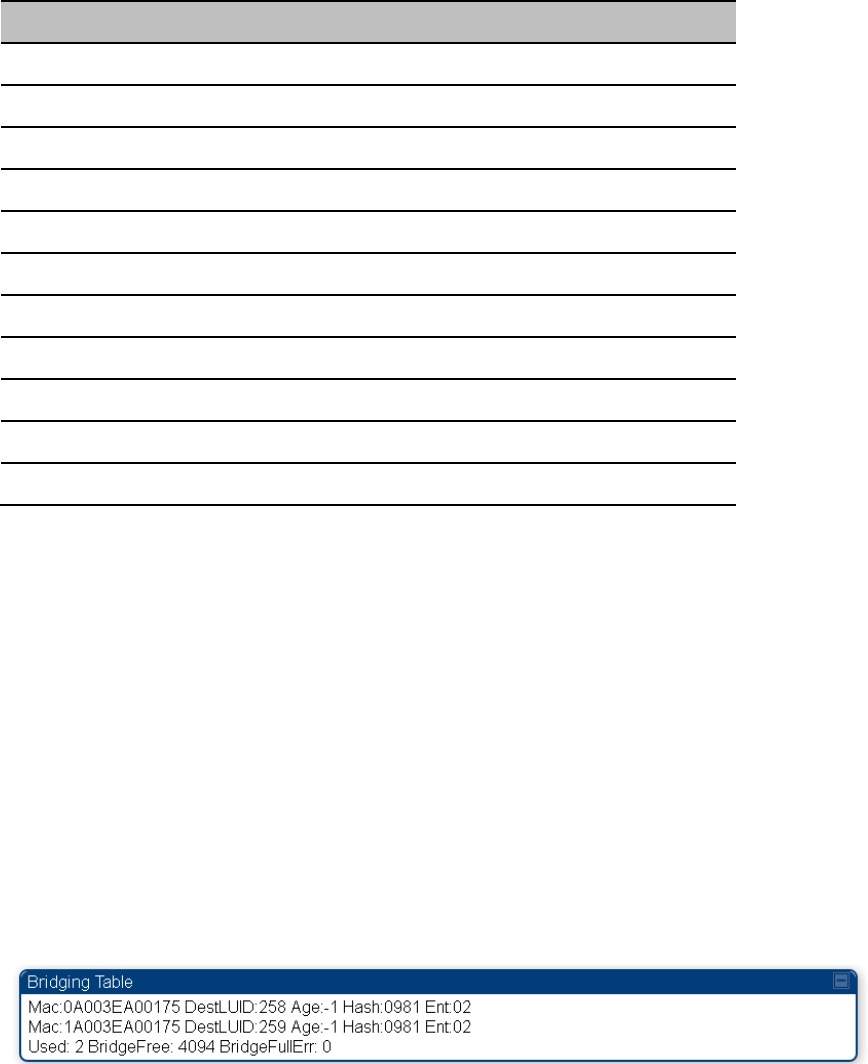
Interpreting Bridging Table statistics
If NAT (network address translation) is not active on the SM/BHS, then the Bridging Table page
provides the MAC address of all devices that are attached to registered SMs/BHS (identified by
LUIDs). The bridging table allows data to be sent to the correct module as follows:
• For the AP/BHM, the uplink is from RF to Ethernet. Thus, when a packet arrives in the RF
interface to the AP/BHM, the AP/BHM reads the MAC address from the inbound packet and
creates a bridging table entry of the source MAC address on the other end of the RF interface.
• For the SM/BHS, the uplink is from Ethernet to RF. Thus, when a packet arrives in the Ethernet
interface to one of these modules, the module reads the MAC address from the inbound packet
and creates a bridging table entry of the source MAC address on the other end of the Ethernet
interface.
Figure 100
Bridging Table page
The Bridging Table supports up to 4096 entries.
Chapter 9: Operation System statistics
Page 9-28
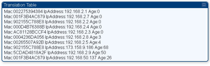
Interpreting Translation Table statistics
When Translation Bridging is enabled in the AP, each SM keeps a table mapping MAC addresses
of devices attached to the AP to IP addresses, as otherwise the mapping of end-user MAC
addresses to IP addresses is lost. (When Translation Bridging is enabled, an AP modifies all uplink
traffic originating from registered SMs such that the source MAC address of every packet is
changed to that of the SM which bridged the packet in the uplink direction.)
Figure 101
Translation Table page - SM
Chapter 9: Operation System statistics
Page 9-29
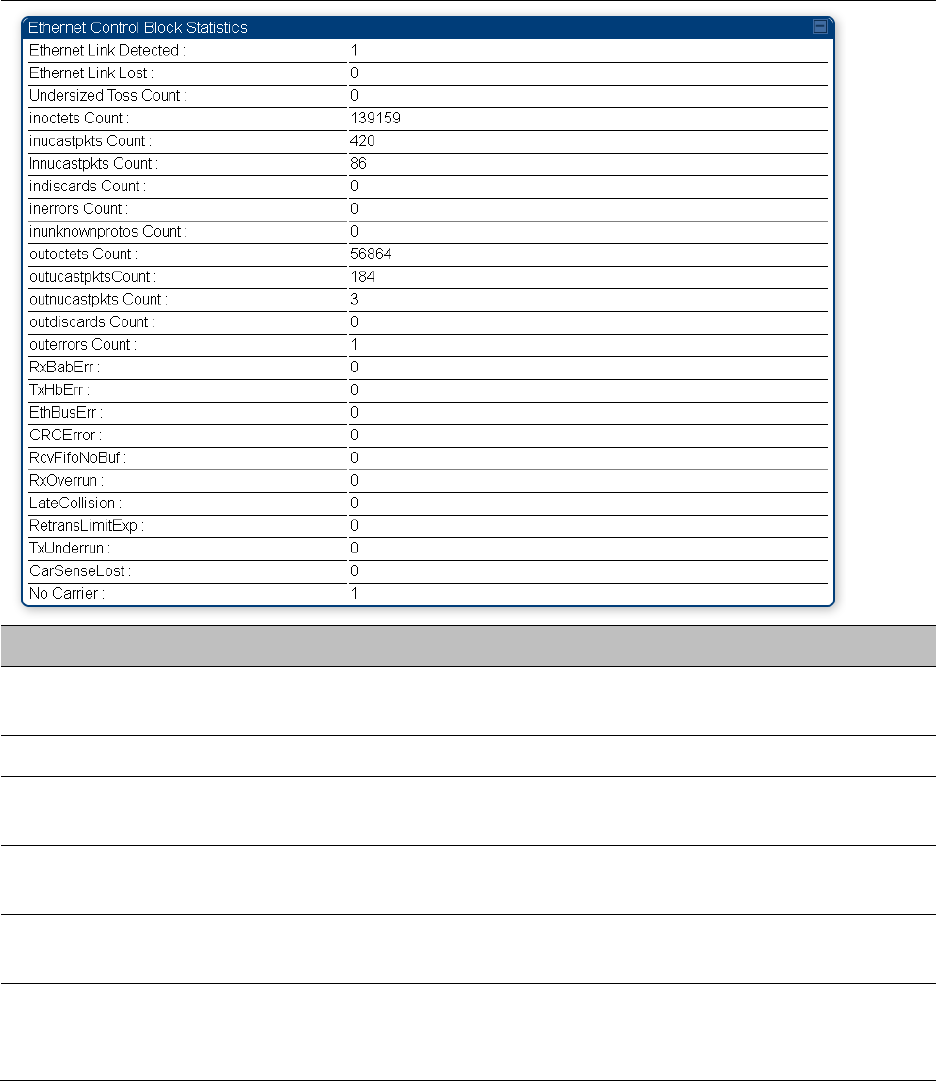
Interpreting Ethernet statistics
The
Statistics > Ethernet
page reports TCP throughput and error information for the Ethernet
connection of the module. This page is applicable for all modules (AP/SM/BHM/BHS).
The
Ethernet
page displays the following fields.
Table 153
Ethernet tab attributes
Attribute
Meaning
Ethernet Link
Detected
1 indicates that an Ethernet link is established to the radio, 0 indicates
that no Ethernet link is established
Ethernet Link Lost This field indicates a count of how many times the Ethernet link was lost.
Undersized Toss
Count
This field indicates the number of packets that were too small to process
and hence discarded.
inoctets Count This field displays how many octets were received on the interface,
including those that deliver framing information.
inucastpkts Count This field displays how many inbound subnetwork-unicast packets were
delivered to a higher-layer protocol.
Innucastpkts Count This field displays how many inbound non-unicast (subnetwork-
broadcast or subnetwork-multicast) packets were delivered to a higher-
layer protocol.

Chapter 9: Operation System statistics
Page 9-30
indiscards Count This field displays how many inbound packets were discarded without
errors that would have prevented their delivery to a higher-layer
protocol. (Some of these packets may have been discarded to increase
buffer space.)
inerrors Count This field displays how many inbound packets contained errors that
prevented their delivery to a higher-layer protocol.
inunknownprotos
Count
This field displays how many inbound packets were discarded because
of an unknown or unsupported protocol.
outoctets Count This field displays how many octets were transmitted out of the
interface, including those that deliver framing information.
outucastpkts Count This field displays how many packets for which the higher-level
protocols requested transmission to a subnetwork-unicast address. The
number includes those that were discarded or not sent.
outnucastpkts Count This field displays how many packets for which the higher-level
protocols requested transmission to a non-unicast (subnetwork-
broadcast or subnetwork-multicast) address. The number includes those
that were discarded or not sent.
outdiscards Count This field displays how many outbound packets were discarded without
errors that would have prevented their transmission. (Some of these
packets may have been discarded to increase buffer space.)
outerrrors Count This field displays how many outbound packets contained errors that
prevented their transmission.
RxBabErr This field displays how many receiver babble errors occurred.
TxHbErr This field displays how many transmit heartbeat errors have occurred.
EthBusErr This field displays how many Ethernet bus errors occurred on the
Ethernet controller.
CRCError This field displays how many CRC errors occurred on the Ethernet
controller.
RcvFifoNoBuf This field displays the number of times no FIFO buffer space was able to
be allocated
RxOverrun This field displays how many receiver overrun errors occurred on the
Ethernet controller.
Late Collision
This field displays how many late collisions occurred on the Ethernet
controller. A normal collision occurs during the first 512 bits of the frame
transmission. A collision that occurs after the first 512 bits is considered
a late collision.
Caution
A late collision is a serious network problem because the frame

Chapter 9: Operation System statistics
Page 9-31
being transmitted is discarded. A late collision is most commonly
caused by a mismatch between duplex configurations at the ends
of a link segment.
RetransLimitExp This field displays how many times the retransmit limit has expired.
TxUnderrun This field displays how many transmission-underrun errors occurred on
the Ethernet controller.
CarSenseLost This field displays how many carrier sense lost errors occurred on the
Ethernet controller.
No Carrier This field displays how many no carrier errors occurred on the Ethernet
controller.
Chapter 9: Operation System statistics
Page 9-32
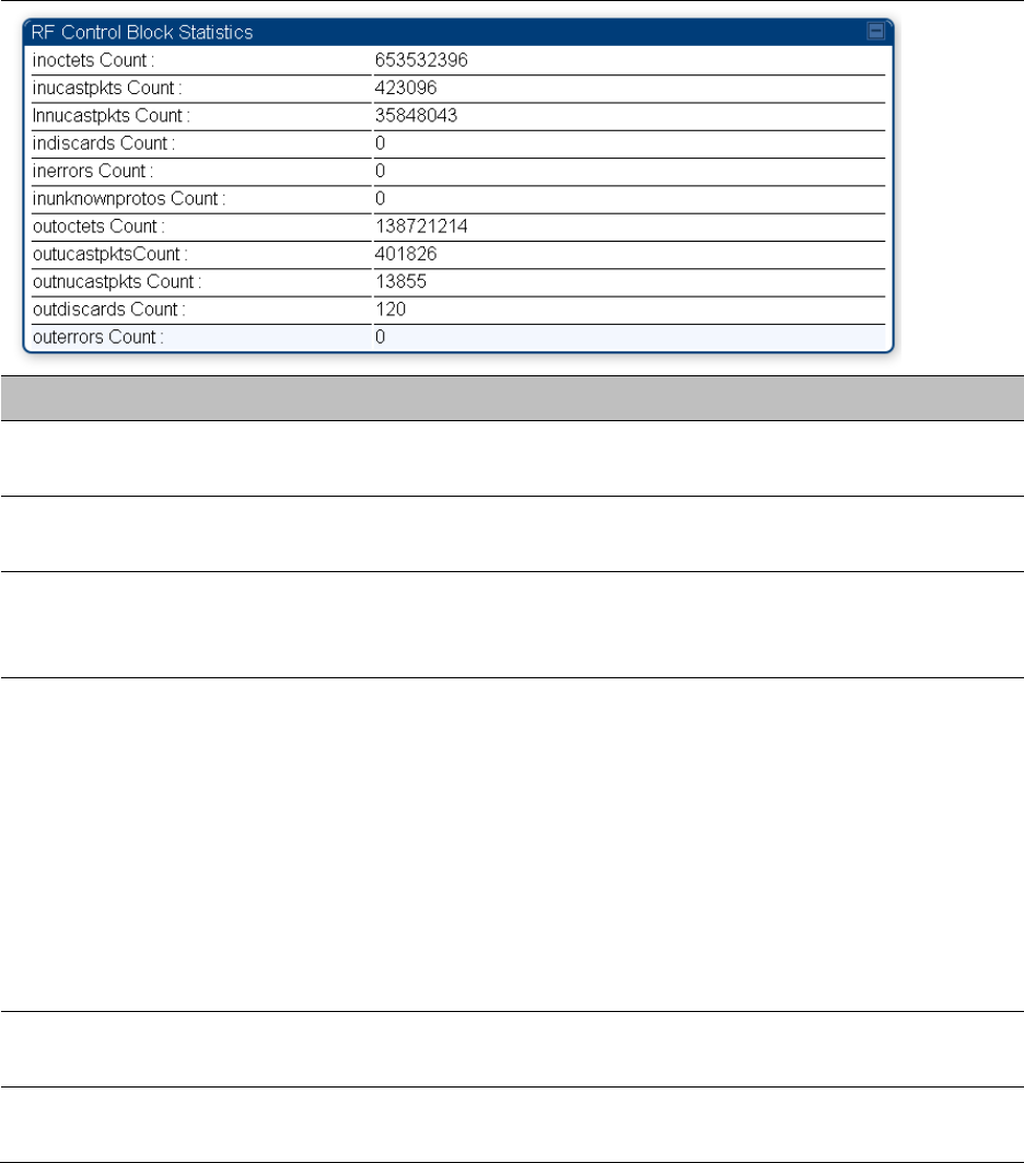
Interpreting RF Control Block statistics
The
Statistics > Radio
page is applicable for all module (AP/SM/BHM/BHS). The Radio page of the
Statistics page displays the following fields.
Table 154
Radio (Statistics) page attributes
Attribute
Meaning
inoctets Count This field displays how many octets were received on the interface,
including those that deliver framing information.
inucastpkts Count This field displays how many inbound subnetwork-unicast packets were
delivered to a higher-layer protocol.
Innucastpkts Count This field displays how many inbound non-unicast (subnetwork-
broadcast or subnetwork-multicast) packets were delivered to a higher-
layer protocol.
indiscards Count This field displays how many inbound packets were discarded without
errors that would have prevented their delivery to a higher-layer
protocol. This stat is pegged whenever corrupt data is received by
software or whenever the RF Software Bridge queue is full.
Corrupt data is a very unusual event because all packets are CRC
checked by hardware before being passed into software.
The likely case for indiscards is if the RF bridge queue is full. If this is the
case the radio is most likely PPS limited due to excessive small packet
traffic or a problem at the Ethernet interface. If there is a problem at the
Ethernet interface there is likely to be discards at the Ethernet as well.
inerrors Count This field displays how many inbound packets contained errors that
prevented their delivery to a higher-layer protocol.
inunknownprotos
Count
This field displays how many inbound packets were discarded because
of an unknown or unsupported protocol.
Chapter 9: Operation System statistics
Page 9-33
outoctets Count This field displays how many octets were transmitted out of the
interface, including those that deliver framing information.
outucastpkts Count This field displays how many packets for which the higher-level
protocols requested transmission to a subnetwork-unicast address. The
number includes those that were discarded or not sent.
outnucastpkts Count This field displays how many packets for which the higher-level
protocols requested transmission to a non-unicast (subnetwork-
broadcast or subnetwork-multicast) address. The number includes those
that were discarded or not sent.
outdiscards Count This field displays how many outbound packets were discarded without
errors that would have prevented their transmission. (Some of these
packets may have been discarded to increase buffer space.)
outerrrors Count This field displays how many outbound packets contained errors that
prevented their transmission.
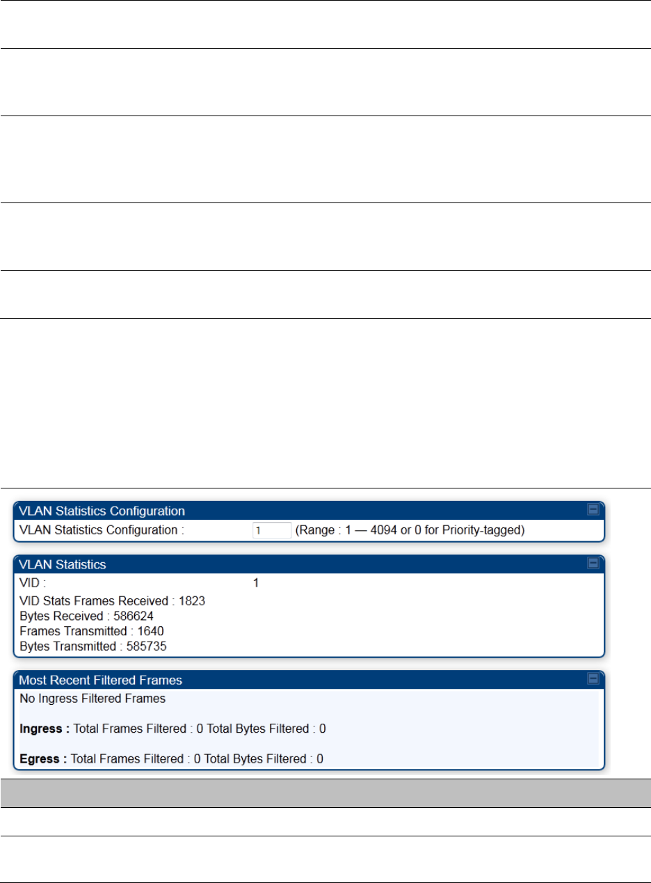
Interpreting VLAN statistics
The
Statistics > VLAN
page provides a list of the most recent packets that were filtered because of
VLAN membership violations. It is applicable for all modules (AP/SM/BHM/BHS).
Table 155
VLAN page attributes
Attribute
Meaning
Unknown This must not occur. Contact Technical Support.
Only Tagged The packet was filtered because the configuration is set to accept only
packets that have an 802.1Q header and this packet did not.

Chapter 9: Operation System statistics
Page 9-34
Ingress When the packet entered through the wired Ethernet interface,
the packet was filtered because it indicated an incorrect VLAN
membership.
Local Ingress When the packet was received from the local TCP/IP stack, the packet
was filtered because it indicated an incorrect VLAN membership.
This must not occur. Contact Technical Support.
Egress When the packet attempted to leave through the wired Ethernet
interface, the packet was filtered because it indicated an incorrect VLAN
membership.
Local Egress When the packet attempted to reach the local TCP/IP stack, the packet
was filtered because it indicated an incorrect VLAN membership.
Chapter 9: Operation System statistics
Page 9-35
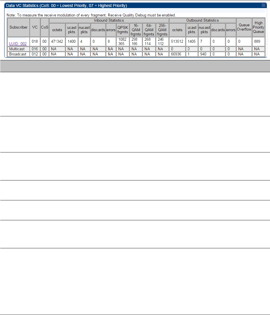
Interpreting Data VC statistics
The
Statistics
>
Data VC
page displays information about Virtual Channel (VC) used in data
communications. This page is applicable for all modules (AP/SM/BHM/BHS).
The
Data VC
tab displays the fields as explained in Table 155.
Table 156
Data VC page attributes
Attribute
Meaning
Subscriber This field displays the LUID (logical unit ID), MAC address and Site Name
of the SM/BHS. As each SM or BHS registers to the AP/BHM, the system
assigns an LUID of 2 or a higher unique number to the SM/BHS. If a
SM/BHS loses registration with the AP/BHM and then regains
registration, the SM/BHS retains the same LUID.
VC This field displays the virtual channel number. Low priority channels
start at VC18 and count up. High priority channels start at VC255 and
count down. If one VC is displayed, the high-priority channel is disabled.
If two are displayed, the high-priority channel is enabled.
CoS This field displays the Class of Service for the virtual channel. The low
priority channel is a CoS of 00 and the high priority channel is a CoS of
01. CoS of 02 through 07 are not currently used.
Inbound Statistics,
octets
This field displays how many octets were received on the interface,
including those that deliver framing information.
Inbound Statistics,
ucastpkts
This field displays how many inbound subnetwork-unicast packets were
delivered to a higher-layer protocol.
Inbound Statistics,
nucastpkts
This field displays how many inbound non-unicast (subnetwork-
broadcast or subnetwork-multicast) packets were delivered to a higher-
layer protocol.
Inbound Statistics,
discards
This field displays how many inbound packets were discarded without
errors that would have prevented their delivery to a higher-layer
protocol. Inbound discard statistics are incremented similar to the
indiscards stat on the RF control block stats page. The sum of all data
VC indiscards must be close to the RF control block in discards. If
indiscards are evenly distributed across SMs, then the radio is PPS
limited due to either excessive small packet transmissions, or a problem
at the Ethernet link. If indiscards are contained to one or a few SMs,

Chapter 9: Operation System statistics
Page 9-36
then there is likely a problem at or underneath the SM which is
incrementing the count.
Inbound Statistics,
errors
This field displays how many inbound packets contained errors that
prevented their delivery to a higher-layer protocol.
Inbound Statistics,
QPSK frgmts
This field displays how many inbound fragments were received via the
QPSK modulation scheme.
Inbound Statistics,
16-QAM frgmts
This field displays how many inbound fragments were received via the
16-QAM modulation scheme.
Inbound Statistics,
64-QAM frgmts
This field displays how many inbound fragments were received via the
64-QAM modulation scheme.
Inbound Statistics,
256-QAM frgmts
This field displays how many inbound fragments were received via the
256-QAM modulation scheme.
Outbound Statistics,
octets
This field displays how many octets were transmitted out of the
interface, including those that deliver framing information.
Outbound Statistics,
ucastpkts
This field displays how many packets for which the higher-level
protocols requested transmission to a subnetwork-unicast address. The
number includes those that were discarded or not sent.
Outbound Statistics,
nucastpkts
This field displays how many packets for which the higher-level
protocols requested transmission to a non-unicast (subnetwork-
broadcast or subnetwork-multicast) address. The number includes those
that were discarded or not sent.
Outbound Statistics,
discards
This field displays how many outbound packets were discarded without
errors that would have prevented their transmission. Outbound discard
statistics are incremented if a VC is not active when a packet is ready to
send. This is a rare condition.
Outbound Statistics,
errors
This field displays how many outbound packets contained errors that
prevented their transmission.
Queue Overflow This is a count of packets that were discarded because the queue for the
VC was already full. If Queue Overflows are being seen across most or
all SMs, then there is either an interferer local to the AP or the APs RF
link is at capacity. If Queue Overflows are being seen at one or only a
few SMs, then it is likely that there is a problem with those specific links
whether it is insufficient signal strength, interferer, or a problem with the
actual SM hardware.
High Priority Queue This is a count of packets that were received on high priority queue.
Chapter 9: Operation System statistics
Page 9-37
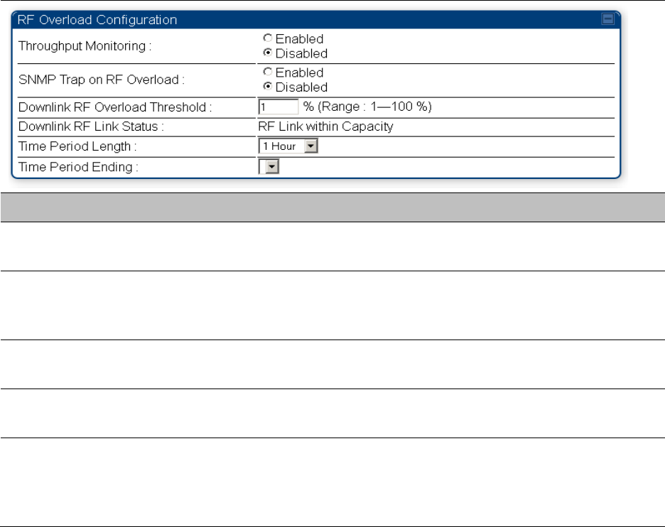
Interpreting Throughput statistics
The PMP/PTP 450i has a
Statistics
>
Throughput
page which shows historical information about
sector or backhaul throughput and packet discards. This page is applicable for AP and BHM
modules. This information can be useful to identify an overloaded sector or heavy bandwidth
users. This page also shows the user throughput in terms of data rate (kbps) and packet rate
(packets per second, or PPS), as well as the average packet size during the sample period.
Operators may set the AP/BHM to send an SNMP trap when it detects an RF overload condition
based on a configurable threshold.
The following configuration parameters are available on the Throughput tab GUI pane and a radio
reboot is not required when configuring these parameters:
Table 157
RF overload Configuration attributes – AP/BHM
Attribute
Meaning
Throughput
Monitoring
This enables or disables the monitoring of sector throughput and packet
discards. This parameter is disabled by default.
SNMP Trap on RF
Overload
This enables or disables the sending of an SNMP trap when an AP/BHM
overload condition is reached (based on Downlink RF Overload
Threshold).
Downlink RF
Overload Threshold
This parameter determines the overload threshold in percent of packets
discarded that triggers the generation of an SNMP trap.
Downlink RF Link
Status
This field displays the status of the capacity of the RF link.
Time Period Length
Time Period Ending
These two configuration parameters determine what set of collection
samples to show on the GUI display. The Time Period Length can be set
from one to three hours. Time Period Ending allows the operator to set
the end time for the set of collection samples to display.
Below the configuration settings are three tables that display the statistics that are collected.
Chapter 9: Operation System statistics
Page 9-38
Board Performance statistics
This table contains a row that corresponds to each 1 minute statistics collection interval. Each row
contains the following data aggregated for the entire AP/BHM:
•
Ethernet Throughput
- Statistics collected at the Ethernet port:
o
kbps in
– average throughput over the collection interval in Kbps into the AP/BHM on the
Ethernet Interface
o
kbps out
– average throughput over the collection interval in Kbps out of the AP/BHM on
the Ethernet Interface
o
PPS in
– average packets per second over the collection interval into the AP/BHM on the
Ethernet Interface
o
PPS out
– average packets per second over the collection interval out of the AP/BHM on the
Ethernet Interface
•
RF Throughput -
Statistics collected at the RF Interface:
o
kbps in
– average throughput over the collection interval in Kbps into the AP/BHM on the
RF Interface
o
kbps out
– average throughput over the collection interval in Kbps out of the AP/BHM on
the RF Interface
o
PPS in
– average packets per second over the collection interval into the AP/BHM on the RF
Interface
o
PPS out
– average packets per second over the collection interval out of the AP/BHM on the
RF Interface
•
Aggregate Through Board
– Sum of bidirectional data transferred through (not originating or
terminating at) the AP/BHM:
o
kbps
– average bidirectional throughput over the collection interval in Kbps
o
PPS
– average bidirectional packets per second over the collection interval
o
Ave Pkt Size
– Average Packet size over the collection interval of bidirectional data
transferred
Board Throughput statistics
This table contains a row that corresponds to each one minute statistics collection interval. This
table may be used to determine if there are problems with any of the interfaces. For example, if
the Ethernet in packets is much higher than the RF out packets it could indicate a denial of service
(DoS) attack on the AP/BHM. Each row contains the following data aggregated for the entire
AP/BHM:
•
Ethernet Statistics
- Statistics collected at the Ethernet port:
o
inOctets
– Number of octets (bytes) received by the AP/BHM at the Ethernet Interface over
the collection interval
o
outOctets
– Number of octets (bytes) sent by the AP/BHM at the Ethernet Interface over the
collection interval
o
inPkts
– Number of packets received by the AP/BHM at the Ethernet Interface over the
collection interval
o
outPkts
– Number of packets sent by the AP/BHM at the Ethernet Interface over the
collection interval
Chapter 9: Operation System statistics
Page 9-39
o
Discards (in/out)
– Number of packets that had to be discarded by the AP/BHM at the
respective Ethernet Interface Queue
•
RF Statistics
- Statistics collected at the RF Interface:
o
inOctets
– Number of octets (bytes) received by the AP/BHM at the RF Interface over the
collection interval
o
outOctets
– Number of octets (bytes) sent by the AP/BHM at the RF Interface over the
collection interval
o
inPkts
– Number of packets received by the AP/BHM at the RF Interface over the collection
interval
o
outPkts
– Number of packets sent by the AP/BHM at the RF Interface over the collection
interval
o
Discards (in/out)
– Number of packets that had to be discarded by the AP/BHM at the
respective RF Interface Queue during the collection interval
o
Discards % (in/out)
– Percent of the total packets received / transmitted that had to be
discarded during the collection interval
LUID RF Throughput statistics
This table contains a row that corresponds to each active LUID served by the AP/BHM. Note that
an LUID may be assigned 1 or 2 VCs. If the LUID is assigned 2 VCs, then the data in the table is the
sum of the activity for both VCs. This table may be used to determine which LUIDs are
experiencing overload so that corrective action can be taken (i.e. fixing a poor RF link or moving a
heavily loaded link to a less congested AP/BHM). Each row contains counters and statistics
related to the RF Interface that are updated once per minute:
•
Inbound Statistics
- Statistics collected at the RF Interface for the Uplink:
o
octets
– Number of octets (bytes) received by the AP/BHM at the RF Interface for this LUID
over the collection interval
o
pkts
– Number of packets received by the AP/BHM at the RF Interface for this LUID over the
collection interval
o
Ave Pkt Size
– Average size of the packets received by the AP/BHM at the RF Interface for
this LUID over the collection interval
o
discards
– Number of packets received by the AP/BHM at the RF Interface for this LUID over
the collection interval that had to be discarded because the RF In Queue was full
o
discards %
– Percent of the total packets received by the AP/BHM at the RF Interface for this
LUID over the collection interval that had to be discarded because the RF In Queue was full
•
Outbound Statistics
- Statistics collected at the RF Interface for the Downlink:
o
octets
– Number of octets (bytes) transmitted by the AP/BHM at the RF Interface for this
LUID over the collection interval
o
pkts
– Number of packets transmitted by the AP/BHM at the RF Interface for this LUID over
the collection interval
o
Ave Pkt Size
– Average size of the packets transmitted by the AP/BHM at the RF Interface
for this LUID over the collection interval
o
discards
– Number of packets to be transmitted by the AP/BHM at the RF Interface for this
LUID over the collection interval that had to be discarded because the RF Out Queue was
full
Chapter 9: Operation System statistics
Page 9-40
o
discards %
– Percent of the total packets to be transmitted by the AP/BHM at the RF
Interface for this LUID over the collection interval that had to be discarded because the RF
Out Queue was full.
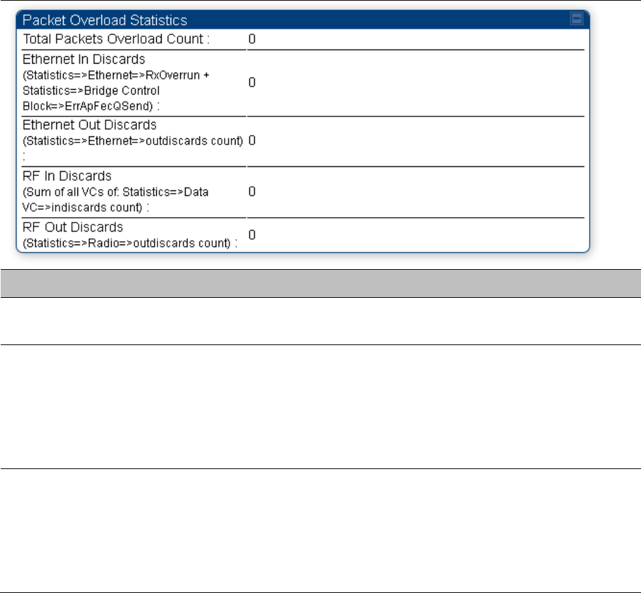
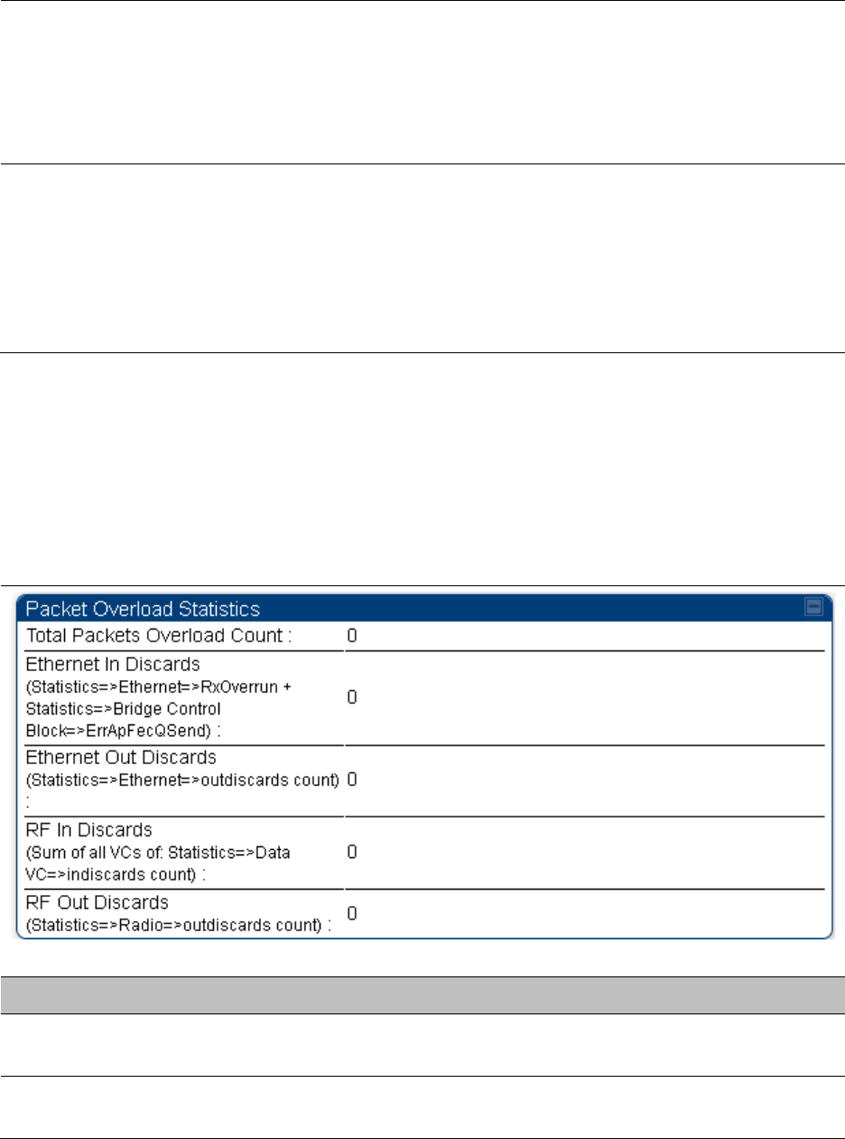
Interpreting Overload statistics
The Statistics > Overload page displays statistics on packet overload and resultant packet discards.
Unlike the other fields, the Total Packets Overload Count is expressed in only this page. It is not a
count of how many packets have been lost, but rather of how many discard events (packet loss
bursts) have been detected due to overload condition.
This statistics page is applicable for all modules (AP/SM/BHM/BHS) and explained in Table 157.
Table 158
Overload page attributes – AP/SM/BHM/BHS
Attribute
Meaning
Total Packets
Overload Count
This field represents the sum of all RF and Ethernet in/out discards.
Ethernet In Discards This field represents the number of packets tossed due to the Ethernet
queue being full. If a climb in this stat accompanies a climb in RF Out
Discards stat, then most likely the board is at RF capacity either due to
traffic exceeding the RF pipe, or interference temporarily limiting the RF
throughput. If this stat climbs without the RF Out Discards stat climbing,
then the radio is most likely PPS limited.
Ethernet Out
Discards
This field represents the number of packets tossed due to an Ethernet
out overload. This stat must not climb in normal operation because the
Ethernet link is much higher capacity than the RF link. If this stat is
incrementing, then either the Ethernet link is established at a low speed
(i.e. 10Mbps – half duplex), or there is a problem with cabling/Ethernet
hardware.
Chapter 9: Operation System statistics
Page 9-41
RF In Discards This field indicates the number of packets tossed due to no resources
available within the radio to process them. This stat also must not be
increasing because the system is designed to shed packets on the RF
Out interface. If this stat is incrementing the board, it is most likely
congested due to high PPS rate in combination with an Ethernet Out
problem, which limits packet flow off the device.
RF Out Discards This field indicates the number of packets tossed due to RF link at
capacity. This stat will increase whenever the RF link is at capacity.
When the internal FPGA RF input queue overflows, this stat is
incremented. If this stat is seen to be incrementing at the AP, then the
sector is congested. If seen at the SM, the number of Contention Slots
must be looked at to ensure that enough Contention Slots are allocated
to allow for bandwidth requests to be seen at the AP.
Interpreting DHCP Relay statistics
The
Statistics > DHCP Relay
page displays requests and replies received, relayed and discarded
when the AP is configured as a DHCP relay. Typically, in a working DHCP relay configuration a
one-to-one ratio is established between requests and replies that are received and relayed. This
statistics page is only applicable for PMP (AP and SM modules) and it is explained in Table 158.
Table 159
DHCP Relay page attributes – AP/SM
Attribute
Meaning
Requests Received This field represents the number of DHCP relay requests received by the
AP.
Requests Relayed This field represents the number of DHCP relay requests relayed by the
AP.
Chapter 9: Operation System statistics
Page 9-42
Requests Discarded This field represents the number of DHCP relay requests discarded by
the AP due to errors in the request.
Replies Received This field represents the number of DHCP relay replies received by the
AP.
Replies Relayed This field represents the number of DHCP relay replies relayed by the
AP.
Replies Discarded This field represents the number of DHCP relay replies discarded by the
AP due to errors in the reply.
Untrusted Message
Discards
This field indicates messages that were discarded because the message
already contained Option 82 information with no Relay Agent specified.
Max Hop Exceeded
Discards
This field indicates messages that have been relayed too many times,
exceeding the max hop count (16).
Invalid Relay Agent
Address Discards
This field indicates messages that have been discarded because the
message relay agent address is already in place (relay agent address
does not equal address of the AP).
Relay Info Exceeding
Max Message Size
(DHCP message
relayed without
Option 82)
This field indicates DHCP messages too large to fit Option 82 data.
These messages are sent on without Option 82 information.
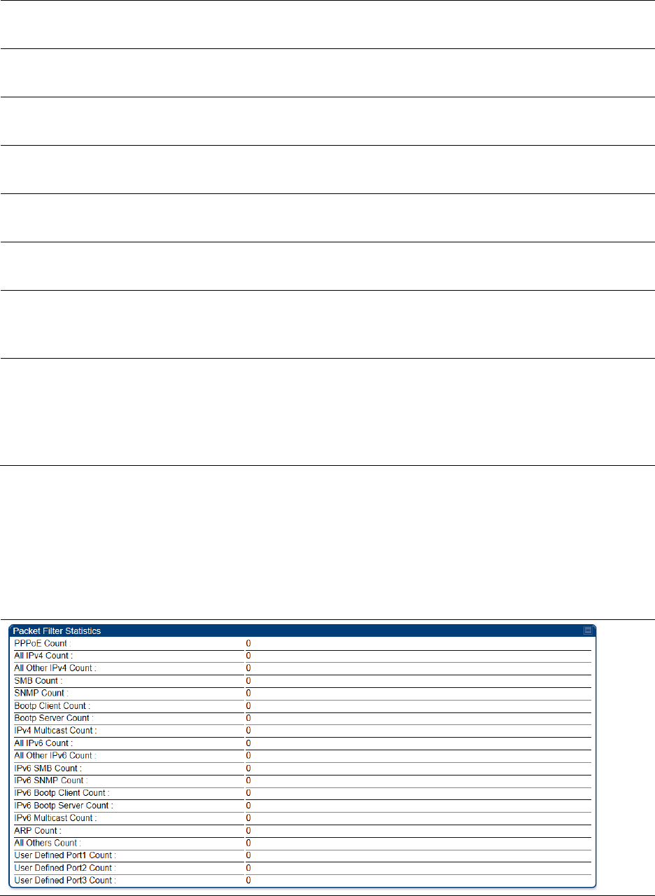
Interpreting Filter statistics
The
Statistics > Filter
page displays statistics on packets that have been filtered (dropped) due to
the filters set on the
Protocol Filtering
page. The filter page of SM is explained in Table 159.
Table 160
Filter page attributes - SM

Chapter 9: Operation System statistics
Page 9-43
Attribute
Meaning
PPPoE Count Number of PPoE packets filtered.
All IPv4 Count Number of IPv4 packets filtered.
All Other IPv4 Count Any IPv4 message that was not SMB, SNMP, Bootp, Multicast or
one of the user defined filters, that was filtered out.
SMB Count Number of IPv4 Server Message Block (file sharing) packets filtered.
SNMP Count Number of IPv4 SNMP packets filtered.
Bootp Client Count Total number of IPv4 DHCP requests filtered.
Bootp Server Count Total number of IPv4 DHCP replies filtered.
IPv4 Multicast Count Number of IPv4 Multicast messages filtered.
All IPv6 Count Number of IPv6 messages filtered.
All Other IPv6 Count Any IPv6 message that was not SMB, SNMP, Bootp, Multicast or
one of the user defined filters, that was filtered out.
IPv6 SMB Count Number of IPv6 Server Message Block (file sharing) packets filtered
IPv6 SNMP Count Number of IPv6 SNMP messages filtred
IPv6 Bootp Client Count Total number of IPv6 DHCP replies filtered
IPv6 Bootp Server Count Total number of IPv6 DHCP replies filtered
IPv6 Multicast Count Number of IPv6 Multicast messages filtered
ARP Count Total number of ARP packets filtered.
All other Count The count of any messages that did not fit above that were filtered
out
User Defined Port1 Count Number of packets defined by the user port1 that were filtered.
User Defined Port2 Count Number of packets defined by the user port2 that were filtered.
User Defined Port3 Count Number of packets defined by the user port3 that were filtered.
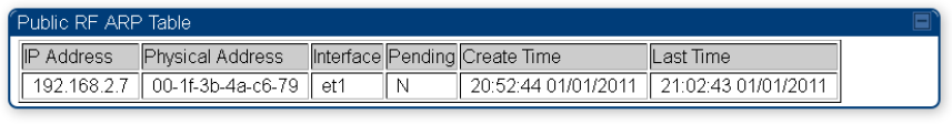
Viewing ARP statistics
The
Statistics > ARP
page in a SM module correlated the IP address of the Ethernet-connected
device to its MAC address and provides data about the connection.
Chapter 9: Operation System statistics
Page 9-44
Figure 102
ARP page of the SM
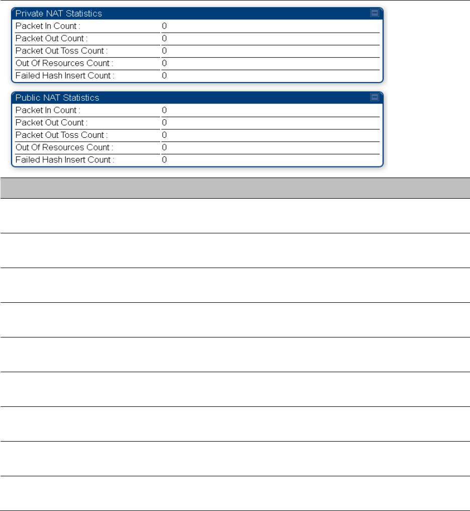
Viewing NAT statistics
When NAT is enabled on a SM, statistics are kept on the Public and Private (WAN and LAN) sides
of the NAT and displayed on the
Statistics > NAT Stats
page. The NAT page of SM is explained in
Table 160.
Chapter 9: Operation System statistics
Page 9-45
Table 161
NAT page attributes - SM
Attribute
Meaning
Private NAT Statistics,
Packet In Count
This field represents the number of packets received on the SM’s
LAN/Ethernet interface
Private NAT Statistics,
Packet Out Count
This field represents the number of packets sent from the SM’s
LAN/Ethernet interface
Private NAT Statistics,
Packet Out Toss Count
This field represents the number of packets that we not sent from the
SM’s LAN/Ethernet interface due to addressing issues.
Private NAT Statistics,
Out of Resources Count
This field represents the number of times the NAT table for the SM’s
LAN/Ethernet interfaces has been filled.
Private NAT Statistics,
Failed Hash Insert Count
This field represents the number of times that the device failed to
insert an address binding into the NAT hash table.
Public NAT Statistics,
Packet In Count
This field represents the number of packets received on the SM’s
WAN/wireless interface
Public NAT Statistics,
Packet Out Count
This field represents the number of packets sent from the SM’s
WAN/wireless interface
Public NAT Statistics,
Out of Resources Count
This field represents the number of packets that we not sent from the
SM’s WAN/wireless interface due to addressing issues.
Public NAT Statistics,
Failed Hash Insert Count
This field represents the number of times the NAT table for the SM’s
WAN/wireless interfaces has been filled.
Chapter 9: Operation System statistics
Page 9-46
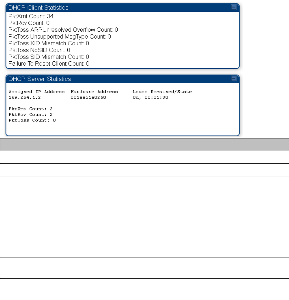
Viewing NAT DHCP Statistics
The Statistics > NAT DHCP page displays NAT enabled DHCP client statistics. This is statistics page
is applicable for SM only.
When NAT is enabled on a SM with DHCP client (
DHCP
selected as the
Connection Type
of the
WAN interface) and/or DHCP Server, statistics are kept for packets transmitted, received and
tossed, as well as a table of lease information for the DHCP server (Assigned IP Address, Hardware
Address and Lease Remained/State).
Table 162
NAT DHCP Statistics page attributes - SM
Attribute
Meaning
PktXmt Count Represents the number of DHCP packets transmitted from the client
PktRcv Count This field represents the number of DHCP packets received by the client
PktToss
ARPUnresolved
Overflow Count
This field represents the number of packets tossed due to failed attempts
to resolve an IP address into a physical MAC address
PktToss
Unsupported
MsgType Count
This field represents the number of packets tossed due to the receipt of
an unsupported message type (cannot be interpreted by DHCP client)
PktToss XID
Mismatch Count
The field represents the number of packets that were tossed due to a
transaction ID mismatch
PktToss NoSID
Count
This field represents the number of packets that were tossed due to lack
of a DHCP session ID
PktToss SID
Mismatch Count
Represents the number of packets tossed due to a session ID mismatch
Chapter 9: Operation System statistics
Page 9-47
Failure to Reset
Client Count
This field represents the number of times the DHCP client was unable to
be reset (resulting in no IP address being served).
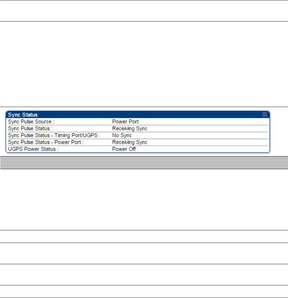
Interpreting Sync Status statistics
The
Statistics > Sync Status
page of AP is only displayed when the Sync Input is set to AutoSync
or AutoSync+Free Run.
The Sync Status page is explained in Table 162.
Table 163
Sync Status page attributes - AP
Attribute
Meaning
Sync Pulse Source This field indicates the status of the synchronization source:
•
Searching
indicates that the unit is searching for a GPS fix
•
Timing Port/UGPS
indicates that the module is receiving sync via the
timing AUX/SYNC timing port
•
Power Port
indicates that the module is receiving sync via the power
port (Ethernet port).
Sync Pulse Status This field indicates synchronization source pulse status.
Sync Pulse Status –
Timing Port/UGPS
This field indicates synchronization pulse status over Timing Port/UGPS
port.
Sync Pulse Status -
Power Port
This field indicates synchronization pulse status over power port.
UGPS Power Status This field indicates UGPS power up status (on or off).
This information may be helpful in a decision of whether to climb a tower to diagnose a perceived
antenna problem.
Chapter 9: Operation System statistics
Page 9-48
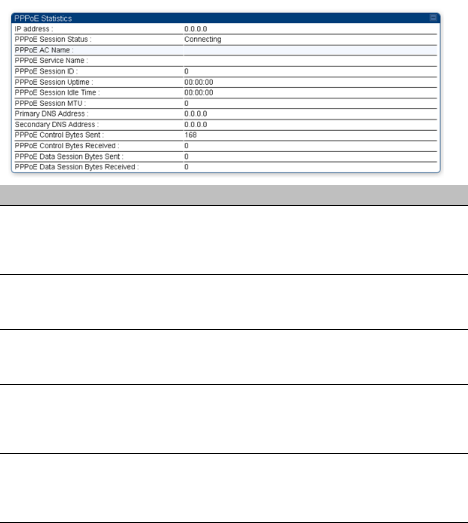
Interpreting PPPoE Statistics for Customer Activities
The page can be access under
Statistics > PPPoE
of SM GUI.
When the PPPoE feature is enabled on the SM, PPPoE statistics provide data about activities of the
customer.
The PPPoE Statistics of SM is explained in Table 163.
Table 164
PPPoE Statistics page attributes - SM
Attribute
Meaning
IP address This field displays the IP address of the PPPoE session initiator (situated
below the SM)
PPPoE Session
Status
This field displays the operational status of the PPPoE Session
PPPoE AC Name This field displays access concentrator name used in the PPPoE session
PPPoE Service Name This field displays the PPPoE service name associated with the PPPoE
server in use
PPPoE Session ID This field displays the current PPPoE session ID
PPPoE Session
Uptime
This field displays the total session uptime for the PPPoE session
PPPoE Session Idle
Time
This field displays the total idle time for the PPPoE session
PPPoE Session MTU This field displays Maximum Transmission Unit configured for the
PPPoE session
Primary DNS
Address
This field displays the primary DNS server used by the PPPoE session
Secondary DNS
Address
This field displays the secondary DNS server used by the PPPoE session
Chapter 9: Operation System statistics
Page 9-49
PPPoE Control Bytes
Sent
Displays the total number of PPPoE session control bytes sent from SM
PPPoE Control Bytes
Received
This field displays the total number of PPPoE session control bytes
received by the SM
PPPoE Data Session
Bytes Sent
This field displays the total number of PPPoE data session (non-
control/non-session management user data) sent by the SM
PPPoE Data Session
Bytes Received
This field displays the total number of PPPoE data session (non-
control/non-session management user data)
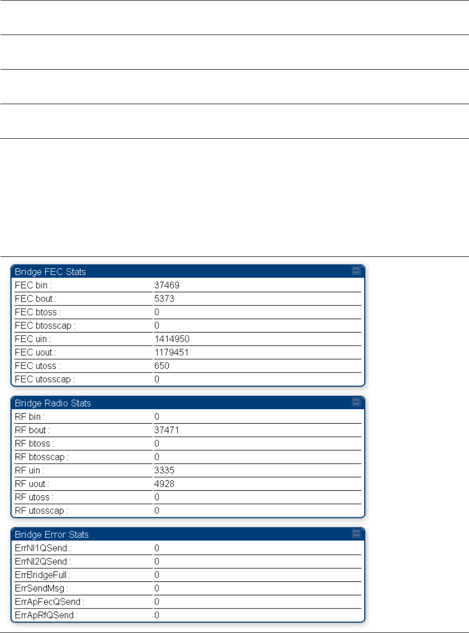
Interpreting Bridge Control Block statistics
The
Statistics > Bridge Control Block
page dipslays statistics of Bridge FEC, Bridge ratio and Bridge
error. The page is applicable for all module (AP/SM/BHM/BHS). The Bridge Control Block Statistics
page is explained in Table 164.
Table 165
Bridge Control Block page attributes – AP/SM/BHM/BHS

Chapter 9: Operation System statistics
Page 9-50
Attribute
Meaning
FEC bin This field indicates the number of broadcast packets received by the
bridge control block on the Ethernet interface
FEC bout This field indicates the number of broadcast packets sent by the bridge
control block on the Ethernet interface
FEC btoss This field indicates the number of broadcast packets tossed out by the
bridge control block on the Ethernet interface
FEC btosscap This field indicates the number of broadcast packets tossed out at the
Ethernet interface due to MIR cap being exceeded.
FEC uin This field indicates the number of unicast packets received by the bridge
control block on the Ethernet interface
FEC uout This field indicates the number of unicast packets sent by the bridge
control block on the Ethernet interface
FEC utoss This field indicates the number of unicast packets tossed by the bridge
control block on the Ethernet interface
FEC utosscap This field indicates the number of unicast packets tossed out at the
Ethernet interface due to MIR cap being exceeded.
RF bin This field indicates the number of broadcast packets received by the
bridge control block on the radio interface
RF bout This field indicates the number of broadcast packets sent by the bridge
control block on the radio interface
RF btoss This field indicates the number of broadcast packets tossed by the
bridge control block on the radio interface
RF btosscap This field indicates the number of broadcast packets tossed out at the
radio interface due to MIR cap being exceeded.
RF uin This field indicates the number of unicast packets received by the bridge
control block on the radio interface
RF uout This field indicates the number of unicast packets sent by the bridge
control block on the radio interface
RF utoss This field indicates the number of unicast packets tossed by the bridge
control block on the radio interface
RF utosscap This field indicates the number of unicast packets tossed out at the radio
interface due to MIR cap being exceeded.
ErrNI1QSend This field indicates that a packet which was sourced from the radio
network stack interface 1 (Ethernet interface) could not be sent because
the radio bridge queue was full. The packet was tossed out.
ErrNI2QSend This field indicates that a packet which was sourced from the radio
Chapter 9: Operation System statistics
Page 9-51
network stack interface 2 (RF interface) could not be sent because the
radio bridge queue was full. The packet was tossed out.
ErrBridgeFull This field indicates the total number of times the bridging table was full
and could not accept new entries.
ErrSendMsg This field displays the error message from bridge core call back routine.
ErrApFecQSend This field indicates that a packet which was received on the Ethernet
interface could not be processed because the radio bridge queue was
full and packet was tossed out.
ErrApRfQSend This field indicates that a packet which was received on the RF interface
could not be processed because the radio bridge queue was full. The
packet was tossed out.
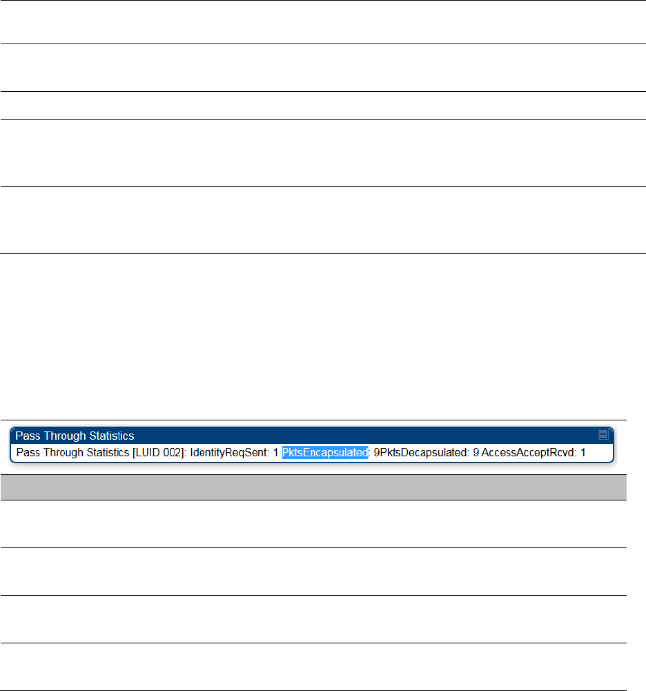
Interpreting Pass Through Statistics
The
Statistics > Pass Through Statistics
page displays radius related statistics. The page is
applicable for PMP 450i AP only. The Pass Through Statistics page is explained in Table 165.
Table 166
Pass Through Statistics page attributes – AP
Attribute
Meaning
IdentityReqSent This field indicates the number of EAP Identity requests sent
through the AP with respect to an SM.
PktsEncapsulated This field indicates no of packets received from the SM which are
encapsulated by the AP.
PktsDecasulated This field indicates no of packets received from the radius server
and are decapsulated by the AP with respect to an SM
AccessAcceptRcvd This field indicates no of RADIUS Access Accept message
received by the AP with respect to an SM.
Chapter 9: Operation System statistics
Page 9-52
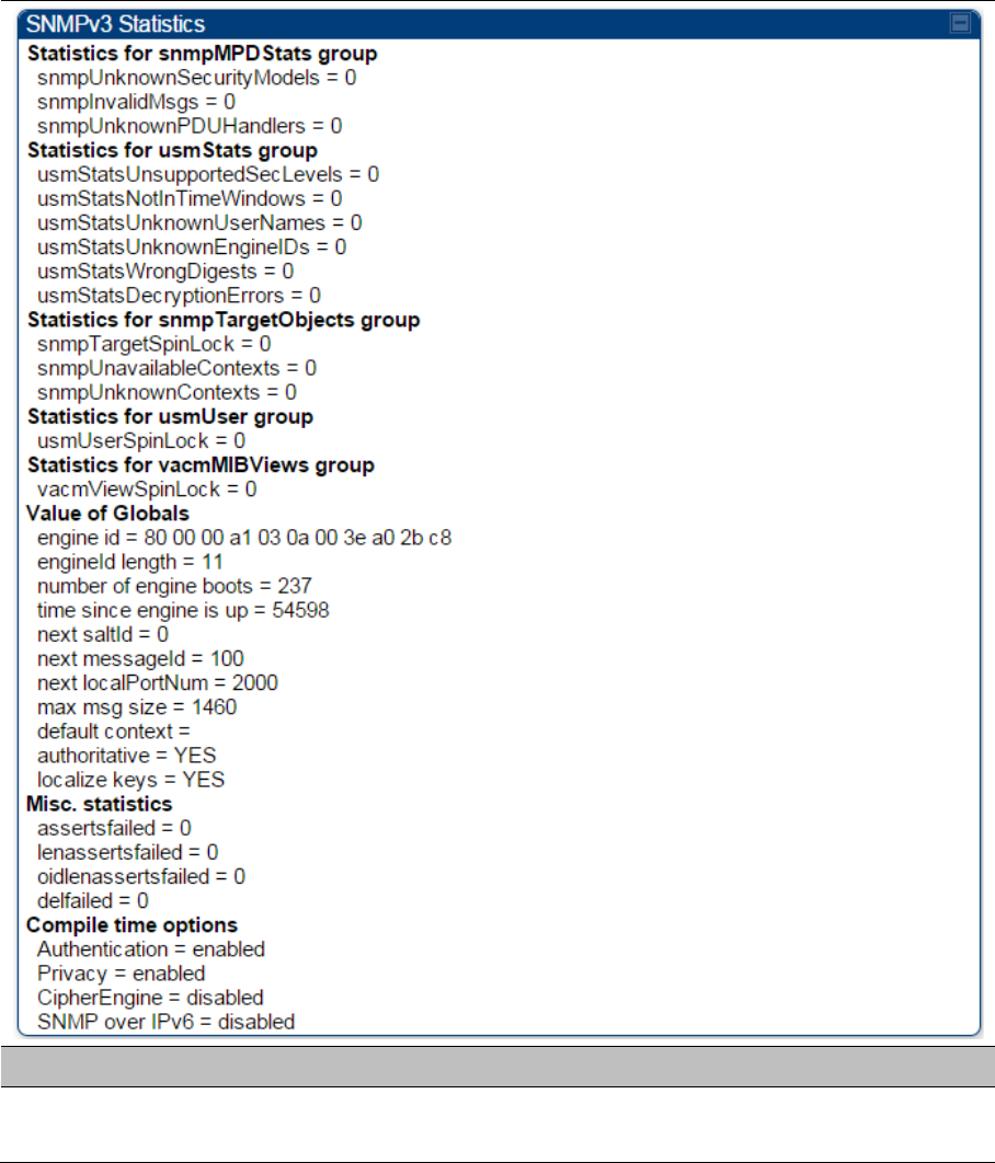
Interpreting SNMPv3 Statistics
The
Statistics > SNMPv3 Statistics
page displays all SNMPv3 related statistics. The page is
applicable for all platform of PMP 450i. The SNMPv3 Statistics page is explained in.
Table 167
SNMPv3 Statistics page attributes – AP
Attribute
Meaning
Statistics for
snmpMPDStats group SNMP Message Processing and Dispatching RFC 3412

Chapter 9: Operation System statistics
Page 9-53
snmpUnknownSecurityM
odels
The total number of packets received by the SNMP engine which
were dropped because they referenced a securityModel that was
not known to or supported by the SNMP engine.
snmpInvalidMsgs The total number of packets received by the SNMP engine which
were dropped because there were invalid or inconsistent
components in the SNMP message.
snmpUnknownPDUHandl
ers
The total number of packets received by the SNMP engine which
were dropped because the PDU contained in the packet could
not be passed to an application responsible for handling the
pduType, e.g. no SNMP application had registered for the proper
combination of the contextEngineID and the pduType.
usmStatsUnsupportedSec
Levels
The total number of packets received by the SNMP engine which
were dropped because they requested a securityLevel that was
unknown to the SNMP engine or otherwise unavailable.
usmStatsNotInTimeWind
ows
The total number of packets received by the SNMP engine which
were dropped because they appeared outside of the
authoritative SNMP engine's window.
usmStatsUnknownUserN
ames
The total number of packets received by the SNMP engine which
were dropped because they referenced a user that was not
known to the SNMP engine.
usmStatsUnknownEngine
IDs
The total number of packets received by the SNMP engine which
were dropped because they referenced a snmpEngineID that was
not known to the SNMP engine.
usmStatsWrongDigests The total number of packets received by the SNMP engine which
were dropped because they didn't contain the expected digest
value.
usmStatsDecryptionError
s
The total number of packets received by the SNMP engine which
were dropped because they could not be decrypted.
snmpTargetSpinLock This object is used to facilitate modification of table entries in the
SNMP-TARGET-MIB module by multiple managers.
snmpUnavailableContext
s
The total number of packets received by the SNMP engine which
were dropped because the context contained in the message
was unavailable.
snmpUnknownContexts The total number of packets received by the SNMP engine which
were dropped because the context contained in the message
was unknown.
usmUserSpinLock The use of usmUserSpinlock is to avoid conflicts with another
SNMP command generator application which may also be acting
on the usmUserTable.
Chapter 9: Operation System statistics
Page 9-54
vacmViewSpinLock An advisory lock used to allow cooperating SNMP Command
Generator applications to coordinate their use of the Set
operation in creating or modifying views.
snmpEngineBoots It is a count of the number of times the SNMP engine has re-
booted/re-initialized since snmpEngineID was last configured
snmpEngineTime
time since engine is up
which is the number of seconds since the snmpEngineBoots
counter was last incremented
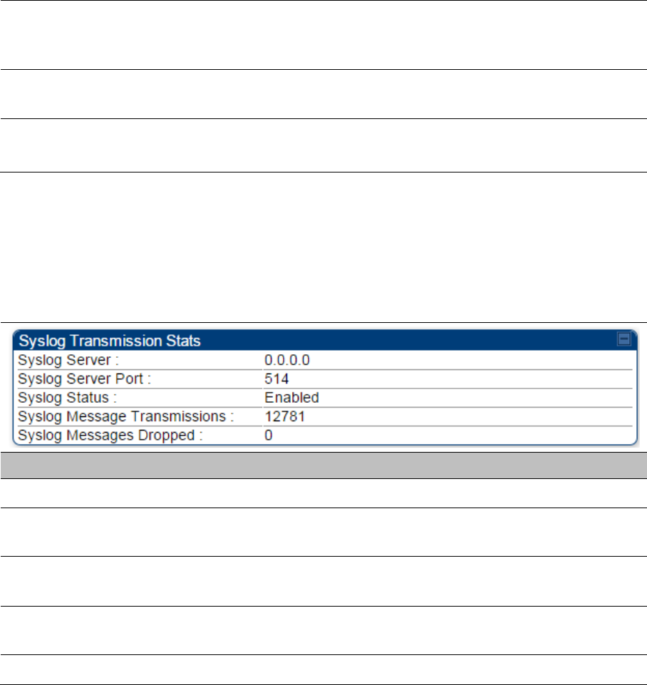
Interpreting syslog statistics
The
Statistics > Syslog Statistics
page dipslays statistics of syslog messages. The page is
applicable for all module (AP/SM/BHM/BHS). The Syslog Statistics page is explained in Table 167.
Table 168
Syslog statistics page attributes – AP/SM/BH
Attribute
Meaning
Syslog Server The dotted decimal or DNS name of the syslog server address.
Syslog Server Port The syslog server port (default 514) to which syslog messaging
is sent.
Syslog Status This indicates status of syslog messaging. It can be Enable or
Disabled based on configuration
Syslog Message
Transmissions
This field indicates the count of syslog messages sent to UDP
layer.
Syslog Message Dropped This field indicates the count of dropped syslog messages.
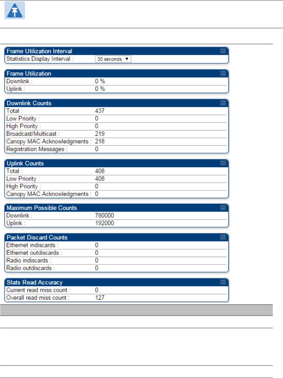
Interpreting Frame Utilization statistics
The Frame Utilization Statistics is a feature helps user to understand how effectively the RF
channel is being utilized. This feature allows to check Time Division Duplex (TDD) frame utilization
pattern and diagnose for any excessive usage in uplink or downlink direction.
This forms the first step of identifying the TDD frame utilization information. If the user finds
excessive utilization based on this stats, the second step would be to take several actions like
sectorization, tuning the uplink/downlink ratio etc. to improve RF channel utilization. Efficient use
of the TDD frame will help to achieve optimum performance of link.
Chapter 9: Operation System statistics
Page 9-55
Note:
The backhauls (BHM and BHS) will have only the downlink scheduler based
statistics
Table 169
Frame utilization statistics
Attribute
Meaning
Frame Utilization Interval
Statistics Display interval This allows to configure timer interval to monitor and display the
frame utilization statistics. It can be configured for 30 seconds
(low interval), 3 minutes (medium interval) or 15 minutes (high
interval) based on requirement.
Frame Utilization

Chapter 9: Operation System statistics
Page 9-56
Downlink This indicates the percentage of downlink data slots used against
the maximum number of slots possible in configured interval.
Uplink This indicates the percentage of uplink data slots used against
the maximum number of uplink slots possible in configured
interval.
Downlink Counts
Total This indicates the sum of all downlink data slots used in the
configured interval.
Low Priority The number of downlink data slots used for low priority
downlink traffic.
High Priority The number of downlink data slots used for high priority
downlink traffic.
Broadcast/Multicast The number of downlink data slots used for broadcast and
multicast traffic.
Canopy MAC
Acknowledgements
The number of downlink data slots used as ACKs.
Registration and Control
message slots
The number of downlink data slots used for registration and
other control messages.
Uplink Counts
Total This indicates the sum of all uplink data slots used in configured
interval.
Low Priority The number of downlink data slots used for low priority uplink
traffic.
High Priority The number of downlink data slots used for high priority
downlink traffic.
Canopy MAC
Acknowledgements
The number of downlink data slots used as ACKs.
Maximum possible counts
Downlink This indicates the maximum possible downlink data slots. This is
based on the configuration of Channel Bandwidth, Frame period,
uplink/downlink allocation, contention slots and configured
Statistics Display interval.
Uplink This indicates the maximum possible uplink data slots. This is
based on the configuration of Channel Bandwidth, Frame period,
uplink/downlink allocation, contention slots and configured
Statistics Display interval.
Packet Discard counts

Chapter 9: Operation System statistics
Page 9-57
Ethernet indiscards This indicates the number of Ethernet packets discarded in the IN
queue.
Ethernet outdiscards This indicates the number of Ethernet packets discarded in the
OUT queue.
Radio indiscards This indicates the number of packets discarded over radio in the
IN queue.
Radio outdiscards This indicates the number of packets discarded over radio in the
OUT queue.
Chapter 9: Operation Radio Recovery Console
Page 9-58
Radio Recovery Console
This section describes how to recover a PMP/PTP 450i unit from configuration errors or software
image corruption.
Entering in Radio Recovery Console
Use this procedure to enter recovery console manually.
Note
The unit may enter recovery console automatically, in response to some failures.
Note
Once the unit has entered recovery, it will switch back to normal operation if no access
has been made to the recovery web page within 30 seconds.
Procedure 32
Recovery mode
1
Apply power to PSU for at least 10 seconds.
2
Remove power for two seconds.
3
Re
-apply power to the PSU.
4
When the unit is in recovery mode, access the web interface by entering the default IP
address
169.254.1.1
. The Recovery Image Warning page is displayed.
5
Review the
Boot Selection (Table 169).
6
Select a
recovery option
Chapter 9: Operation Radio Recovery Console
Page 9-59
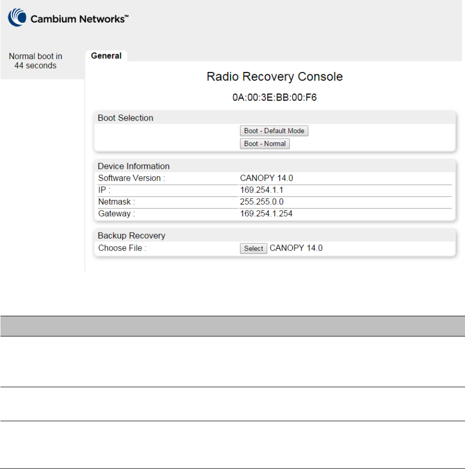
Figure 103
Recovery Options page
Table 170
Recovery Options attributes
Attribute
Meaning
Boot Selection
Boot – Default Mode
: Use this option to temporarily set the IP and
Ethernet attributes to factory defaults until the next reboot.
Boot – Normal
: Use this option to reboot the unit.
IP address, Netmask,
Gateway
These fields display IP address, Netmask and Gateway of the radio while
it is in recovery or default mode.
Backup Recovery
Choose File
Use this option to restore a working software version when software
corruption is suspected, or when an incorrect software image has been
loaded.

Page 10-1
Chapter 10: Reference Information
This chapter contains reference information and regulatory notices that apply to the PMP/PTP 450i
Series products.
The following topics are described in this chapter:
• Equipment specifications on page 10-2 contains specifications of the PMP/PTP 450i, ODU
specifications including RF bands, channel width and link loss.
• Data network specifications on page 10-13
shows the PMP/PTP 450i Ethernet interface
specifications.
• Compliance with safety standards on page 10-16 lists the safety specifications against which
the PMP/PTP 450i has been tested and certified. It also describes how to keep RF exposure
within safe limits.
• Compliance with radio regulations on page 10-17 describes how the PMP/PTP 450i complies
with the radio regulations that are enforced in various countries.
• Equipment Disposal on page 10-2 shows the notifications made to regulatory bodies for the
PMP/PTP 450i.

Chapter 10: Reference Information Equipment specifications
Page 10-2
Equipment specifications
This section contains specifications of the AP, SM, BHM and BHS associated supplies required for
PMP/PTP 450i installations.
Specifications for AP
The PMP 450i AP conforms to the specifications listed in Table 170.
Table 171
AP specifications
Category
Specification
Model Number PMP 450i AP
Spectrum
Channel Spacing 5, 10 and 20 MHz Channel Bandwidth
Configurable on 2.5 MHz increments
Frequency Range 4900 - 5925 MHz
Channel Width 5, 10 and 20 MHz
Interface
MAC (Media Access
Control) Layer
Cambium Proprietary
Physical Layer 2x2 MIMO OFDM
Ethernet Interface 10/100/1000BaseT, half/full duplex, rate auto negotiated
(802.3 compliant)
Protocols Used IPv4, UDP, TCP, IP, ICMP, Telnet, SNMP, HTTP, FTP
Network Management HTTP, HTTPS, Telnet, FTP, SNMP v3
VLAN 802.1ad (DVLAN Q-inQ), 802.1Q with 802.1p priority,
dynamic port VID
Sensitivity
Nominal Receive
Sensitivity (w/ FEC) @
5 MHz Channel
4.9 GHz 1x = --90 dBm, 2x = -85.7 dBm, 4x = -80 dBm, 6x = -72.4
dBm, 8x = -65.7 dBm
5.4 GHz 1x = --91 dBm, 2x = -86.3 dBm, 4x = -79.8 dBm, 6x = -
73.5 dBm, 8x = -66 dBm
5.8 GHz 1x = -91 dBm, 2x = -86.3 dBm, 4x = --79.8 dBm, 6x = -

Chapter 10: Reference Information Equipment specifications
Page 10-3
73.5 dBm, 8x = -66 dBm
Nominal Receive
Sensitivity (w/ FEC) @
10 MHz Channel
4.9 GHz 1x = --87.9 dBm, 2x = -84.1 dBm, 4x = -78 dBm, 6x = -
71.5 dBm, 8x = -64.8 dBm
5.4 GHz 1x = --88 dBm, 2x = -84.1 dBm, 4x = -77.1 dBm, 6x = -
71.2 dBm, 8x = -64.2 dBm
5.8 GHz 1x = --88 dBm, 2x = -84.1 dBm, 4x = -77.1 dBm, 6x = -
71.2 dBm, 8x = -64.2 dBm
Nominal Receive
Sensitivity (w/ FEC) @
20 MHz Channel
4.9 GHz 1x = --85.6 dBm, 2x = -80.4 dBm, 4x = -74.3 dBm, 6x = -
68.2 dBm, 8x = -61 dBm
5.4 GHz 1x = --86 dBm, 2x = -82 dBm, 4x = -75 dBm, 6x = -68.9
dBm, 8x = -61 dBm
5.8 GHz 1x = --86 dBm, 2x = -82 dBm, 4x = -75 dBm, 6x = -68.9
dBm, 8x = -61 dBm
Performance
ARQ Yes
Cyclic Prefix 1/16
Frame Period 2.5 ms or 5.0 ms
Modulation Levels
(Adaptive)
Modution Levels MCS SNR (in dB)
2x QPSK 10
4x 16QAM 17
6x 64QAM 24
8x 256QAM 32
Latency 3 - 5 ms
Maximum Deployment
Range
Up to 40 miles (64 km)
GPS Synchronization Yes, via Autosync (CMM4), via uGPS
Quality of Service Diffserv QoS
Link Budget
Antenna Beam Width 90° (3dB rolloff) sector for integrated (Dual polarity,
H+V)

Chapter 10: Reference Information Equipment specifications
Page 10-4
Antenna Gain (Does
not include cable loss,
~1dB)
5 GHz 16 dBi integrated 90° sector or external
Transmit Power Range 40 dB dynamic range (to EIRP limit by region) (1 dB
step)
Maximum Transmit
Power
+27 dBm combined output
Physical
Sync/AUX port
RJ45 • 10/100/100BASE-T Ethernet Data
• PoE output
• Sync input or output (Connection and powering of
UGPS Sync input)
Antenna Connection 50 ohm, N-type (Connectorized version only)
Surge Suppression
EN61000-4-5
EN61000-4-5: 1.2us/50us, 500 V voltage waveform
Recommended external surge suppressor: Cambium
Networks Model # C000000L033A
Mean Time Between
Failure
> 40 Years
Environmental IP66, IP67
Temperature /
Humidity
-40°C to +60°C (-40°F to +140°F), 0-95% non-
condensing
Weight Connectorized Approx. 2.0 kg (4.5 lbs)
Integrated Approx. 2.5 kg (5.5 lbs)
Wind Survival Connectorized 322 km/h (200 mi/h)
Integrated 200 km/h (124 mi/h)
Dimension(HxWxD) Connectorized 26.0 x 13.4 x 6.4 cm (10.3” x 5.3” x 3.3”)
Integrated 37.0 x 37.0 x 6.3 cm (14.5” x 14.5” x 3.2”)
Power Consumption 15 W typical, 25 W max, 55 W max with Aux port PoE
out enabled
Input Voltage 48-59 V DC, 802.3at compliant
Mounting Wall or Pole mount with Cambium Networks Model #
N000045L002A
Security

Chapter 10: Reference Information Equipment specifications
Page 10-5
Encryption 56-bit DES, FIPS-197 128-bit AES

Chapter 10: Reference Information Equipment specifications
Page 10-6
Specifications for SM
The PMP 450i SM conforms to the specifications listed in Table 171.
Table 172
PMP 450i SM specifications
Category
Specification
Model Number PMP 450i SM
Spectrum
Channel Spacing 5, 10 and 20 MHz Channel Bandwidth
Configurable on 2.5 MHz iments
Frequency Range 4900 - 5925 MHz
Channel Width 5, 10 and 20 MHz
Interface
MAC (Media Access
Control) Layer
Cambium Proprietary
Physical Layer 2x2 MIMO OFDM
Ethernet Interface 10/100/1000BaseT, half/full duplex, rate auto negotiated
(802.3 compliant)
Protocols Used IPv4, UDP, TCP, IP, ICMP, Telnet, SNMP, HTTP, FTP
Network Management HTTP, HTTPS, Telnet, FTP, SNMP v2c and v3
VLAN 802.1ad (DVLAN Q-inQ), 802.1Q with 802.1p priority,
dynamic port VID
Sensitivity
Nominal Receive
Sensitivity (w/ FEC) @
5 MHz Channel
4.9 GHz 1x = -93 dBm, 2x = -88.5 dBm, 4x = -81.4 dBm, 6x = -75
dBm, 8x = -67.5 dBm
5.4 GHz 1x = -93 dBm, 2x = -88.7 dBm, 4x = -82.4 dBm, 6x = -
76.1 dBm, 8x = -68.5 dBm
5.8 GHz 1x = -93 dBm, 2x = -89.6 dBm, 4x = -82.6 dBm, 6x = -
76.4 dBm, 8x = -67 dBm
Nominal Receive
Sensitivity (w/ FEC) @
10 MHz Channel
4.9 GHz 1x = -89.7 dBm, 2x = -84.6 dBm, 4x = -78.6 dBm, 6x = -
71.7 dBm, 8x = -65.7 dBm
5.4 GHz 1x = -89.5 dBm, 2x = -86.3 dBm, 4x = -79.3 dBm, 6x = -
73.1 dBm, 8x = -65.4 dBm

Chapter 10: Reference Information Equipment specifications
Page 10-7
5.8 GHz 1x = -90 dBm, 2x = -85.2 dBm, 4x = -78.7 dBm, 6x = -73
dBm, 8x = -65.2 dBm
Nominal Receive
Sensitivity (w/ FEC) @
20 MHz Channel
4.9 GHz 1x = -86.8 dBm, 2x = -82 dBm, 4x = -75.7 dBm, 6x = -
69.4 dBm, 8x = -62.7 dBm
5.4 GHz 1x = -86.1 dBm, 2x = -82.3 dBm, 4x = -76 dBm, 6x = -
69.3 dBm, 8x = -62.3 dBm
5.8 GHz 1x = -87.5 dBm, 2x = -83.1 dBm, 4x = -76.3 dBm, 6x = -
69.1 dBm, 8x = -61.3 dBm
Performance
ARQ Yes
Cyclic Prefix 1/16
Frame Period 2.5 ms or 5.0 ms
Modulation Levels
(Adaptive)
Modution Levels MCS SNR (in dB)
2x QPSK 10
4x 16QAM 17
6x 64QAM 24
8x 256QAM 32
Latency 3 - 5 ms
Maximum Deployment
Range
Up to 40 miles (64 km)
GPS Synchronization Yes, via Autosync (CMM4)
Quality of Service Diffserv QoS
Link Budget
Antenna Beam Width 10° azimuth for 23 dBi integrated antenna
Antenna Gain (Does
not include cable loss,
~1dB)
5 GHz +23 dBi H+V, integrated or external
Transmit Power Range 40 dB dynamic range (to EIRP limit by region) (1 dB
step)
Maximum Transmit
Power
+27 dBm combined output

Chapter 10: Reference Information Equipment specifications
Page 10-8
Physical
Sync/AUX port
RJ45 • 10/100/100BASE-T Ethernet Data
• PoE output
• Sync input or output (Connection and powering of
UGPS Sync input)
Antenna Connection 50 ohm, N-type (Connectorized version only)
Surge Suppression
EN61000-4-5
EN61000-4-5: 1.2us/50us, 500 V voltage waveform
Recommended external surge suppressor: Cambium
Networks Model # C000000L033A
Mean Time Between
Failure
> 40 Years
Environmental IP66, IP67
Temperature /
Humidity
-40°C to +60°C (-40°F to +140°F), 0-95% non-
condensing
Weight Connectorized Approx. 2.0 kg (4.5 lbs)
Integrated Approx. 2.5 kg (5.5 lbs)
Wind Survival Connectorized 322 km/h (200 mi/h)
Integrated 200 km/h (124 mi/h)
Dimension(HxWxD) Connectorized 26.0 x 13.4 x 6.4 cm (10.3” x 5.3” x 3.3”)
Integrated 31.0 x 31.0 x 6.4 cm (12” x 12” x 2.5”)
Power Consumption 15 W typical, 25 W max, 55 W max with Aux port PoE
out enabled
Input Voltage 48-59 V DC, 802.3at compliant
Mounting Wall or Pole mount with Cambium Networks Model #
N000045L002A
Security
Encryption 56-bit DES, FIPS-197 128-bit AES

Chapter 10: Reference Information Equipment specifications
Page 10-9
Specifications for BH
The PTP 450i BH conforms to the specifications listed in Table 172.
Table 173
PMP 450i BH specifications
Category
Specification
Model Number PMP 450i BH
Spectrum
Channel Spacing 5, 10 and 20 MHz Channel Bandwidth
Configurable on 2.5 MHz increataements
Frequency Range 4900 - 5925 MHz
Channel Width 5, 10 and 20 MHz
Interface
MAC (Media Access
Control) Layer
Cambium Proprietary
Physical Layer 2x2 MIMO OFDM
Ethernet Interface 10/100/1000BaseT, half/full duplex, rate auto negotiated
(802.3 compliant)
Protocols Used IPv4, UDP, TCP, IP, ICMP, Telnet, SNMP, HTTP, FTP
Network Management HTTP, HTTPS, Telnet, FTP, SNMP v2c and v3
VLAN 802.1ad (DVLAN Q-inQ), 802.1Q with 802.1p priority,
dynamic port VID
Sensitivity
Nominal Receive
Sensitivity (w/ FEC) @
5 MHz Channel
4.9 GHz 1x = -92.7 dBm, 2x = -88.1 dBm, 4x = -81 dBm, 6x = -75
dBm, 8x = -67.8 dBm
5.4 GHz 1x = -92.4 dBm, 2x = -88.4 dBm, 4x = -81.3 dBm, 6x = -
75.5 dBm, 8x = -67.8 dBm
5.8 GHz 1x = -92.3 dBm, 2x = -87.5 dBm, 4x = -80.4 dBm, 6x = -
74 dBm, 8x = -67.2 dBm
Nominal Receive
Sensitivity (w/ FEC) @
10 MHz Channel
4.9 GHz 1x = -89.2 dBm, 2x = -85.1 dBm, 4x = -77.8 dBm, 6x = -
72 dBm, 8x = -64.9 dBm
5.4 GHz 1x = -90 dBm, 2x = -85 dBm, 4x = -78.7 dBm, 6x = -71.6
dBm, 8x = -64.4 dBm
5.8 GHz 1x = -89.9 dBm, 2x = -84.3 dBm, 4x = -78 dBm, 6x = -
71.5 dBm, 8x = -64 dBm

Chapter 10: Reference Information Equipment specifications
Page 10-10
Nominal Receive
Sensitivity (w/ FEC) @
20 MHz Channel
4.9 GHz 1x = -87.1 dBm, 2x = -82.1 dBm, 4x = -74.7 dBm, 6x = -
69.2 dBm, 8x = -61.2 dBm
5.4 GHz 1x = -86 dBm, 2x = -81.6 dBm, 4x = -74.9 dBm, 6x = -
68.4 dBm, 8x = -61 dBm
5.8 GHz 1x = -86.6 dBm, 2x = -80.4 dBm, 4x = -74.7 dBm, 6x = -
68.5 dBm, 8x = -61 dBm
Performance
ARQ Yes
Cyclic Prefix 1/16
Frame Period 2.5 ms or 5.0 ms
Modulation Levels
(Adaptive)
Modution Levels MCS SNR (in dB)
2x QPSK 10
4x 16QAM 17
6x 64QAM 24
8x 256QAM 32
Latency 3 - 5 ms
Maximum Deployment
Range
Up to 40 miles (64 km)
GPS Synchronization Yes, via Autosync (CMM4)
Quality of Service Diffserv QoS
Link Budget
Antenna Beam Width 10° azimuth for 23 dBi integrated antenna
Antenna Gain (Does
not include cable loss,
~1dB)
5 GHz +23 dBi H+V, integrated or external
Transmit Power Range 40 dB dynamic range (to EIRP limit by region) (1 dB
step)
Maximum Transmit
Power
+27 dBm combined output
Physical
Sync/AUX port
RJ45 • 10/100/100BASE-T Ethernet Data
• PoE output
•
Sync input or output (Connection and powering of

Chapter 10: Reference Information Equipment specifications
Page 10-11
UGPS Sync input)
Antenna Connection 50 ohm, N-type (Connectorized version only)
Surge Suppression
EN61000-4-5
EN61000-4-5: 1.2us/50us, 500 V voltage waveform
Recommended external surge suppressor: Cambium
Networks Model # C000000L033A
Mean Time Between
Failure
> 40 Years
Environmental IP66, IP67
Temperature /
Humidity
-40°C to +60°C (-40°F to +140°F), 0-95% non-
condensing
Weight Connectorized Approx. 2.0 kg (4.5 lbs)
Integrated Approx. 2.5 kg (5.5 lbs)
Wind Survival Connectorized 322 km/h (200 mi/h)
Integrated 200 km/h (124 mi/h)
Dimension(HxWxD) Connectorized 26.0 x 13.4 x 6.4 cm (10.25” x 5.25” x 3.25”)
Integrated 31.0 x 31.0 x 6.4 cm (12” x 12” x 2.5”)
Power Consumption 15 W typical, 25 W max, 55 W max with Aux port PoE
out enabled
Input Voltage 48-59 V DC, 802.3at compliant
Mounting Wall or Pole mount with Cambium Networks Model #
N000045L002A
Security
Encryption 56-bit DES, FIPS-197 128-bit AES

Chapter 10: Reference Information Equipment specifications
Page 10-12
PSU specifications
The PTP 450i AC+DC Enhanced Power Injector conforms to the specifications listed in Table 173.
Table 174
AC Power Injector
specifications
Category
Specification
Dimensions 137 mm (5.4 in) x 56 mm (2.2 in) x 38 mm (1.5 in)
Weight 0.240 Kg (0.5 lbs)
Temperature 0°C to +40°C
Humidity 90% non-condensing
Waterproofing Not waterproof
Altitude Sea level to 5000 meters (16000 ft)
AC Input Min 90 V AC, 57 – 63 Hz, max 264 V AC, 47 – 53 Hz.
DC output voltage to the ODU 55V +/- 5%
AC connector IEC-320-C8
Efficiency Better than 85%, efficiency level ‘V’
Over Current Protection Hiccup current limiting, trip point set between 120% to
150% of full load current
Hold up time At least 10 milliseconds

Chapter 10: Reference Information Data network specifications
Page 10-13
Data network specifications
This section contains specifications of the PMP/PTP 450i Ethernet interface.
Ethernet interface
The PMP/PTP 450i Main Ethernet port conforms to the specifications listed in
Table 174.
Table 175
PMP/PTP 450i Main Ethernet bridging specifications
Ethernet Bridging
Specification
Protocol IEEE 802.3 compatible
QoS IEEE 802.1p, IEEE 802.1Q, IEEE 802.1ad, DSCP IPv4
Interface 10/100/1000 BaseT, half/full duplex, rate auto negotiated
Maximum Ethernet Frame
Size
1700 Bytes
Note
Practical Ethernet rates depend on network configuration, higher layer protocols and
platforms used.
Over the air throughput is restricted to the rate of the Ethernet interface at the
receiving end of the link.

Chapter 10: Reference Information Wireless specifications
Page 10-14
Wireless specifications
This section contains specifications of the PMP/PTP 450i wireless interface. These specifications
include RF bands, channel bandwidth, spectrum settings, maximum power and link loss.
General wireless specifications
The wireless specifications that apply to all PMP/PTP 450i variants are listed under Table 175.
Table 176
PMP/PTP 450i wireless specifications
Item Specification
Channel selection Manual selection (fixed frequency).
Manual power control To avoid interference to other users of the band,
maximum power can be set lower than the default power
limit.
Duplex scheme Adaptive TDD
Range 5 GHz – 40 mi / 64 km
Over-the-air encryption DES, AES
Error Correction Rate 3/4 RS coder

Chapter 10: Reference Information Wireless specifications
Page 10-15
Link range
Example of the link ranges for PMP and PTP modes are provided in Table 176 and Table 177.
These assumes the transmit power is not limited by the country of operation for the selected band.
PMP 450i
Table 177
Link range – PMP 5.8 GHz link, 20 MHz Channel Bandwidth, 2.5ms frame duration,
antenna gain of 17 dBi at AP and 23 dBi at the SM
Parameter
Range Details (km)
1x
2x
4x
6x
8x
Modulation QPSK-
MIMO-A
QPSK-
MIMO-B
16QAM-
MIMO-B
64QAM-
MIMO-B
256QAM-
MIMO-B
Max. LOS
(no fade margin) 239.6 68.3 35.4 16.8 6.7
Max. nLOS
(additional 5 dB link loss) 134.8 38.4 19.9 9.4 3.8
Max. NLOS1
(additional 15 dB link loss) 42.6 12.1 6.3 3.0 1.2
Max. NLOS2
(additional 25 dB link loss) 13.5 3.8 2.0 0.9 0.4
PTP 450i
Table 178
Link range – PTP 5.8 GHz link, 20 MHz Channel Bandwidth, 2.5ms frame duration,
antenna gain of 23 dBi at each end
Parameter
Range Details (km)
1x
2x
4x
6x
8x
Modulation QPSK-
MIMO-A
QPSK-
MIMO-B
16QAM-
MIMO-B
64QAM-
MIMO-B
256QAM-
MIMO-B
Max. LOS
(no fade margin) 239.6 136.3 70.7 33.5 13.3
Max. nLOS
(additional 5 dB link loss) 134.8 76.7 39.8 18.8 7.5
Max. NLOS1
(additional 15 dB link loss) 42.6 24.2 12.6 6.0 2.4
Max. NLOS2
(additional 25 dB link loss) 13.5 7.7 4.0 1.9 0.7
Chapter 10: Reference Information Compliance with safety standards
Page 10-16
Compliance with safety standards
This section lists the safety specifications against which the PMP/PTP 450i has been tested and
certified. It also describes how to keep RF exposure within safe limits.
Electrical safety compliance
The PMP/PTP 450i hardware has been tested for compliance to the electrical safety specifications
listed in Table 178.
Table 179
PMP 450 safety compliance specifications
Region
Specification
USA UL 60950
Canada CSA C22.2 No.60950
International CB certified & certificate to IEC 60950
Electromagnetic compatibility (EMC) compliance
The EMC specification type approvals that have been granted for PMP/PTP 450i are listed under
Table 179.
Table 180
EMC emissions compliance
Region
Specification
USA FCC Part 15 Class B
Canada RSS Gen
EU EN 301 489-1 V1.9.2
EN 301 489-17 V2.1.1

Chapter 10: Reference Information Compliance with radio regulations
Page 10-17
Compliance with radio regulations
This section describes how the PMP/PTP 450i complies with the radio regulations that are enforced
in various countries.
Caution
Changes or modifications not expressly approved by Cambium could void the user’s
authority to operate the system.
Type approvals
This system has achieved Type Approval in various countries around the world. This means that
the system has been tested against various local technical regulations and found to comply. The
frequency bands in which the system operates may be ‘unlicensed’ and, in these bands, the
system can be used provided it does not cause interference. The system is not guaranteed
protection against interference from other products and installations.
The radio specification type approvals that have been granted for PMP 450 frequency variants are
listed under Table 180.
Table 181
Radio certifications
Region/Country
Band
Specification
Brazil 4.9 GHz ANATEL, RESOLUÇÃO Nº 633, DE 14 DE MARÇO DE 2014
5.4 GHz ANATEL, RESOLUTION No. 506, FROM JULY 1, 2008
5.8 GHz ANATEL, RESOLUTION No. 506, FROM JULY 1, 2008
Mexico 4.9 GHz Protocol Between the UNITED STATES OF AMERICA and
MEXICO – Use of 4940 to 4990 MHz band.
5.4 GHz Acuerdo del 27 de noviembre de 2012
5.8 GHz NOM-121-SCT1-2009
USA 4.9 GHz FCC 47 CFR Part 90
5.1 GHz FCC 47 CFR Part 15 E
5.8 GHz FCC 47 CFR Part 15 C
Canada
(Pending)
4.9 GHz IC RSS-111 Issue 5
5.8 GHz IC RSS-247 Issue 1
Europe 4.9 GHz ETSI EN302 625; V1.1.1 Broadband Disaster Relief

Chapter 10: Reference Information Compliance with radio regulations
Page 10-18
DFS for 5 GHz Radios
Dynamic Frequency Selection (DFS) is a requirement in several countries and regions for 5 GHz
unlicensed systems to detect radar systems and avoid co-channel operation.
The details of DFS operation and channels available for each Country Code, including whether DFS
is active on the AP, SM, which DFS regulation apply, and any channel restrictions are shown in
Table 181 on page 10-18.
Table 182
Country & Bands DFS setting
Region
Code
Country Code
Band
AP
SM
Weather
Radar
Notch-Out
North
America
Mexico 5.4 GHz ETSI EN 301 893
v1.8.1 DFS
No effect No
South
America
Brazil 5.4 GHz ETSI EN 301 893
v1.8.1 DFS
No effect No
Europe ETSI 5.4 GHz ETSI EN 301 893
v1.8.1 DFS
ETSI EN 301 893
v1.8.1 DFS
Yes
5.8 GHz ETSI EN 302 502
v1.2.1 DFS
ETSI EN 302 502
v1.2.1 DFS
Yes
Other-
Regulatory
Other-FCC 5.4 GHz FCC DFS FCC DFS No
Other-ETSI 5.4 GHz ETSI EN 301 893
v1.8.1 DFS
ETSI EN 301 893
v1.8.1 DFS
No
5.8 GHz ETSI EN 302 502
v1.2.1 DFS
ETSI EN 302 502
v1.2.1 DFS
No

Chapter 10: Reference Information Compliance with radio regulations
Page 10-19
Maximum transmit power per Country Code
Table 183
Default combined transmit power per Country Code – 4.9 GHz band
Countries
Device
Type
Antenna Type
Channel BW
Conducted
Power Limit
(dBm)
EIRP Limit
(dBm)
USA,
Mexico,
Canada,
Other FCC
AP Sector 5 MHz 24 40
10 MHz 24 40
20 MHz 23 39
Omni 5 MHz 24 35
10 MHz 24 36
20 MHz 23 35
SM, BH Flate plate 5 MHz 24 51
10 MHz 24 51
20 MHz 23 50
4ft parabolic 5 MHz 24 52
10 MHz 24 55
20 MHz 23 56
6ft parabolic 5 MHz 24 52
10 MHz 24 55
20 MHz 23 58
Brazil Any Any 5 MHz 23 54
10 MHz 27 57
20 MHz 27 60
Other Any Any Any 27 -

Chapter 10: Reference Information Compliance with radio regulations
Page 10-20
Table 184
Default combined transmit power per Country Code – 5.1 GHz band
Countries
Device
Type
Antenna Type
Channel BW
Conducted
Power Limit
(dBm)
EIRP Limit
(dBm)
USA,
Other FCC
AP Sector 5 MHz 12 30
10 MHz 15 30
20 MHz 16 30
Omni 5 MHz 16 30
10 MHz 17 30
20 MHz 17 30
SM, BH Flate plate 5 MHz -2 30
10 MHz 1 30
20 MHz 3 30
4ft parabolic 5 MHz 6 30
10 MHz 9 30
20 MHz 9 30

Chapter 10: Reference Information Compliance with radio regulations
Page 10-21
Table 185
Default combined transmit power per Country Code – 5.4 GHz band
Countries
Device
Type
Antenna Type
Channel BW
Conducted
Power Limit
(dBm)
EIRP Limit
(dBm)
Brazil Any Any 10 MHz 19 30
20 MHz 23 30
Mexico Any Any 10 MHz - 30
20 MHz - 30
Other Any Any Any 27 -
Table 186
Default combined transmit power per Country Code – 5.8 GHz band
Countries
Device
Type
Antenna Type
Channel BW
Conducted
Power Limit
(dBm)
EIRP Limit
(dBm)
USA,
Canada,
Brazil,
Other FCC
AP Sector,
Omni
5 MHz - 36
10 MHz - 36
20 MHz - 36
SM, BH Flat plate,
4ft parabolic,
6ft parabolic
5 MHz 27 -
10 MHz 27 -
20 MHz 27 -
Mexico Any Any 5 MHz - 30
10 MHz - 33
20 MHz - 36
Other Any Any 5 MHz 27 -
FCC compliance
4.9 GHz FCC notification
The system has been approved under FCC Part 90 for Public Safety Agency usage. The installer or
operator is responsible for obtaining the appropriate site licenses before installing or using the
system.
Chapter 10: Reference Information Compliance with radio regulations
Page 10-22
5 GHz FCC notification
This device complies with part 15C of the US FCC Rules. Operation is subject to the following two
conditions: (1) This device may not cause harmful interference, and (2) This device must accept
any interference received, including interference that may cause undesired operation.
This equipment has been tested and found to comply with the limits for a Class B digital device,
pursuant to Part 15 of the US FCC Rules. These limits are designed to provide reasonable
protection against harmful interference in a residential installation. This equipment generates,
uses, and can radiate radio-frequency energy and, if not installed and used in accordance with
these instructions, may cause harmful interference to radio communications. If this equipment
does cause harmful interference to radio or television reception, which can be determined by
turning the equipment on and off, the user is encouraged to correct the interference by one or
more of the following measures:
• Increase the separation between the affected equipment and the unit;
• Connect the affected equipment to a power outlet on a different circuit from which the receiver
is connected to.
• Consult the dealer and/or experienced radio/TV technician for help.
Where necessary, the end user is responsible for obtaining any National licenses required to
operate this product and these must be obtained before using the product in any particular
country. Contact the appropriate national administrations for details on the conditions of use for
the bands in question and any exceptions that might apply.
Chapter 10: Reference Information Compliance with radio regulations
Page 10-23
FCC compliance testing
With GPS synchronization installed, the system has been tested for compliance to US (FCC)
specifications. It has been shown to comply with the limits for emitted spurious radiation for a
Class B digital device, pursuant to Part 15 of the FCC Rules in the USA. These limits have been
designed to provide reasonable protection against harmful interference. However the equipment
can radiate radio frequency energy and, if not installed and used in accordance with the
instructions, may cause harmful interference to other radio communications. There is no
guarantee that interference does not occur in a particular installation.
Note
A Class B Digital Device is a device that is marketed for use in a residential
environment, notwithstanding use in commercial, business and industrial
environments.
Note
Notwithstanding that Cambium has designed (and qualified) the PMP/PTP 450i
products to generally meet the Class B requirement to minimize the potential for
interference, the PMP/PTP 450i product range is not marketed for use in a residential
environment.
FCC IDs
Table 187
US FCC IDs
FCC ID
Product
Frequency
Band
Channel
Bandwidth
Frequencies
Maximum
Combined Tx
Output Power
QWP-
50450I
5 GHz
AP, SM &
BH
4.9 GHz
5 MHz 4942.5 – 4987.5 MHz 24 dBm
10 MHz 4945.0 – 4985.0 MHz 24 dBm
20 MHz 4950.0 – 4980.0 MHz 23.5 dBm
5.1 GHz
5 MHz 5156.0 – 5247.5 MHz 16 dBm
10 MHz 5160.0 – 5164.75 MHz 17 dBm
5165.0 – 5245.0 MHz 19 dBm
20 MHz 5169.0 – 5175.75 MHz 17 dBm
5176.0 – 5240.0 MHz 23 dBm
5.8 GHz
5 MHz 5730.0 – 5845.0 MHz 28 dBm
10 MHz 5730.0 – 5845.0 MHz 28 dBm
20 MHz 5735.0 – 5840.0 MHz 28 dBm

Chapter 10: Reference Information Compliance with radio regulations
Page 10-24
FCC approved antenna list
Table 188
USA approved antenna list 4.9 GHz
Directivity
Type
Manufacturer
Reference
Stated Gain
(dBi)
Directional
Integrated flat
plate
Cambium
Networks
N/A 23.0
2 ft dual polarised
flat plate
Mars Antennas MA-WA56-DP-28N 28.0
4 ft parabolic dual
polarised
Gabriel
Antennas
Dual QuickFire QFD4-49-N 33.7
6 ft Parabolic dual
polarised
Gabriel
Antennas
QuickFire QF6-49-N 37.2
Sector
Integrated 90°
sector flat plate
Cambium
Networks
N/A 16.0
90° sectorised Cambium
Networks
#85009324001 17.0
60° sectorised Cambium
Networks
#85009325001 17.0
Omni-
directional
Dual polar omni-
directional
KP KPPA-5.7-DPOMA 13.0

Chapter 10: Reference Information Compliance with radio regulations
Page 10-25
Table 189
USA approved antenna list 5.1 and 5.2 GHz
Directivity
Type
Manufacturer
Reference
Stated Gain
(dBi)
Directional
Integrated flat
plate
Cambium
Networks
N/A 23.0
2 ft dual polarised
flat plate
Mars Antennas MA-WA56-DP-28N 28.5
4 ft parabolic dual
polarised
Gabriel
Antennas
PX4F-52-N7A/A 34.5
Sector
Integrated 90°
sector flat plate
Cambium
Networks
N/A 16.0
90° sectorised Cambium
Networks
#85009324001 17.0
Omni-
directional
Dual polar omni-
directional
KP KPPA-5.7-DPOMA 13.0
Dual polar omni-
directional
Mars Antennas MA-WO56-DP10 10.0
Table 190
USA approved antenna list 5.4 GHz
Directivity
Type
Manufacturer
Reference
Stated Gain
(dBi)
Directional
Integrated flat
plate
Cambium
Networks
N/A 23.0
2 ft dual polarised
flat plate
Mars Antennas MA-WA56-DP-28N 28.5
2 ft dual polarised
parabolic
MTI MT-486013-NVH 28.5
Sector
Integrated 90°
sector flat plate
Cambium
Networks
N/A 16.0
90° sectorised Cambium
Networks
#85009324001 17.0
Omni-
directional
Dual polar omni-
directional
KP KPPA-5.7-DPOMA 13.0
Dual polar omni-
directional
Mars Antennas MA-WO56-DP10 10.0

Chapter 10: Reference Information Compliance with radio regulations
Page 10-26
Table 191
USA approved antenna list 5.8 GHz
Directivity
Type
Manufacturer
Reference
Stated Gain
(dBi)
Directional
Integrated flat
plate
Cambium
Networks
N/A 23.0
2 ft dual polarised
flat plate
Mars Antennas MA-WA56-DP-28N 28.0
4 ft parabolic dual
polarised
Gabriel
Antennas
PX4F-52-N7A/A 35.3
6 ft Parabolic dual
polarised
Gabriel
Antennas
PX6F-52/A 38.1
Sector
Integrated 90°
sector flat plate
Cambium
Networks
N/A 16.0
90° sectorised Cambium
Networks
#85009324001 17.0
60° sectorised Cambium
Networks
#85009325001 17.0
Omni-
directional
Dual polar omni-
directional
KP KPPA-5.7-DPOMA 13.0
Chapter 10: Reference Information Compliance with radio regulations
Page 10-27
Industry Canada certification
4.9 GHz IC notification
The system has been approved under Industry Canada RSS-111 for Public Safety Agency usage.
The installer or operator is responsible for obtaining the appropriate site licenses before installing
or using the system.
Utilisation de la bande 4.9 GHz FCC et IC
Le système a été approuvé en vertu de Industrie Canada RSS-111 pour l'utilisation par l'Agence de
la Sécurité publique. L'installateur ou l'exploitant est responsable de l'obtention des licences de
appropriées avant d'installer ou d'utiliser le système.
5.2 GHz and 5.4 GHz IC notification
This device complies with Industry Canada RSS-247. Operation is subject to the following two
conditions: (1) This device may not cause harmful interference, and (2) This device must accept
any interference received, including interference that may cause undesired operation. Users
should be cautioned to take note that high power radars are allocated as primary users (meaning
they have priority) of 5250 – 5350 MHz and 5650 – 5850 MHz and these radars could cause
interference and/or damage to license-exempt local area networks (LELAN).
For the connectorized version of the product and in order to reduce potential radio interference to
other users, the antenna type and its gain should be so chosen that the equivalent isotropically
radiated power (EIRP) is not more than that permitted by the regulations. The transmitted power
must be reduced to achieve this requirement.
Utilisation de la bande 5.2 and 5.4 GHz IC
Cet appareil est conforme à Industrie Canada RSS-247. Son fonctionnement est soumis aux deux
conditions suivantes: (1) Ce dispositif ne doit pas causer d'interférences nuisibles, et (2) Cet
appareil doit tolérer toute interférence reçue, y compris les interférences pouvant entraîner un
fonctionnement indésirable. Les utilisateurs doivent prendre garde au fait que les radars à haute
puissance sont considères comme les utilisateurs prioritaires de 5250 à 5350 MHz et 5650 à 5850
MHz et ces radars peuvent causer des interférences et / ou interférer avec un réseau local ne
nécessitant pas de licence.
Pour la version du produit avec antenne externe et afin de réduire le risque d'interférence avec
d'autres utilisateurs, le type d'antenne et son gain doivent être choisis afin que la puissance
isotrope rayonnée équivalente (PIRE) ne soit pas supérieure à celle permise par la règlementation.
Il peut être nécessaire de réduire la puissance transmise doit être réduite pour satisfaire cette
exigence.

Chapter 10: Reference Information Compliance with radio regulations
Page 10-28
IC notification 5.8 GHz
RSS-GEN issue 3 (7.1.3) Licence-Exempt Radio Apparatus:
This device complies with Industry Canada license-exempt RSS standard(s). Operation is
subject to the following two conditions: (1) this device may not cause interference, and (2) this
device must accept any interference, including interference that may cause undesired
operation of the device.
In Canada, high power radars are allocated as primary users (meaning they have priority) of the
5650 – 5850 MHz spectrum. These radars could cause interference or damage to license-exempt
local area network (LE-LAN) devices.
Utilisation de la bande 5.8 GHz IC
RSS-GEN issue 3 (7.1.3) appariel utilisant la bande sans license:
Le présent appareil est conforme aux CNR d'Industrie Canada applicables aux appareils radio
exempts de licence. L'exploitation est autorisée aux deux conditions suivantes : (1) l'appareil
ne doit pas produire de brouillage, et (2) l'utilisateur de l'appareil doit accepter tout brouillage
radioélectrique subi, même si le brouillage est susceptible d'en compromettre le
fonctionnement.
Au Canada, les radars à haute puissance sont désignés comme utilisateurs principaux (ils ont la
priorité) de la 5650 - spectre 5850 MHz. Ces radars peuvent causer des interférences et / ou
interférer avec un réseau local ne nécessitant pas de licence.
IC certification numbers
Table 192
Industry Canada Certification Numbers
IC Cert. #
Product
Frequency
Band
Channel
Bandwidth
Frequencies
Maximum
Combined Tx
Output Power
109AO-
50450I
(Pending)
5 GHz
AP, SM &
BHM
4.9 GHz
5 MHz 4942.5 – 4987.5 MHz 24 dBm
10 MHz 4945.0 – 4985.0 MHz 24 dBm
20 MHz 4950.0 – 4980.0 MHz 23.5 dBm
5.8 GHz
5 MHz 5730.0 – 5845.0 MHz 28 dBm
10 MHz 5730.0 – 5845.0 MHz 28 dBm
20 MHz 5735.0 – 5840.0 MHz 28 dBm
Chapter 10: Reference Information Compliance with radio regulations
Page 10-29
Canada approved antenna list
Under Industry Canada regulations, this radio transmitter may only operate using an antenna of a
type and maximum (or lesser) gain approved for the transmitter by Industry Canada. To reduce
potential radio interference to other users, the antenna type and its gain must be so chosen that
the equivalent isotropically radiated power (EIRP) is not more than that necessary for successful
communication.
Conformément à la réglementation d'Industrie Canada, le présent émetteur radio peut fonctionner
avec une antenne d'un type et d'un gain maximal (ou inférieur) approuvé pour l'émetteur par
Industrie Canada. Dans le but de réduire les risques de brouillage radioélectrique à l'intention des
autres utilisateurs, il faut choisir le type d'antenne et son gain de sorte que la puissance isotrope
rayonnée équivalente (PIRE) ne dépasse pas l'intensité nécessaire à l'établissement d'une
communication satisfaisante.
This radio transmitter (identify the device by certification number) has been approved by Industry
Canada to operate with the antenna types listed in Compliance with radio regulations, Industry
Canada certification, Table 192 and Table 193 with the maximum permissible gain and required
antenna impedance for each antenna type indicated. Antenna types not included in this list, having
a gain greater than the maximum gain indicated for that type, are strictly prohibited for use with
this device.
Le présent émetteur radio (identifier le dispositif par son numéro de certification) a été approuvé
par Industrie Canada pour fonctionner avec les types d'antenne énumérés dans la section
Compliance with radio regulations, Industry Canada certification, Table 192 and Table 193 et ayant
un gain admissible maximal et l'impédance requise pour chaque type d'antenne. Les types
d'antenne non inclus dans cette liste, ou dont le gain est supérieur au gain maximal indiqué, sont
strictement interdits pour l'exploitation de l'émetteur.

Chapter 10: Reference Information Compliance with radio regulations
Page 10-30
Table 193
Canada approved antenna list 4.9 and 5.8 GHz
Antenna
type
Description
Manufacturer
Reference
Gain (dBi)
4.9 GHz
5.8 GHz
Directional
Integrated flat
plate
Cambium
Networks
N/A 23 23
2 ft dual
polarised flat
plate
MARS
Antennas
MA-WA56-DP-28N
28.5 28
4 ft parabolic
dual polarised
Andrews
Antennas
PX4F-52-N7A/A N/A 35.3
6 ft Parabolic
dual polarised
Gabriel
Antennas
QF6-49-N 37.2 N/A
Sector
Integrated
90° sector flat
plate
Cambium
Networks
N/A
16 16
90°sector Cambium
Networks
85009324001 17 17
60° sectorised Cambium
Networks
#85009325001 16 16
Omni-
directional
Omni-
directional
KP Antennas KPPA-5.7-DPOMA 13 13
Omni-
directional
MARS
Antennas
MA-WO56-DP10 10 10

Chapter 10: Reference Information Compliance with radio regulations
Page 10-31
Table 194
Canada approved antenna list 5.2 and 5.4 GHz
Directivity
Type
Manufacturer
Reference
Stated Gain
(dBi)
Directional
Integrated flat
plate
Cambium
Networks
N/A 23.0
2 ft dual polarised
flat plate
Mars Antennas MA-WA56-DP-28N 28.5
2 ft dual polarised
parabolic
MTI MT-486013-NVH 28.5
Sector
Integrated 90°
sector flat plate
Cambium
Networks
N/A 16.0
90° sectorised Cambium
Networks
#85009324001 17.0
Omni-
directional
Dual polar omni-
directional
KP KPPA-5.7-DPOMA 13.0
Dual polar omni-
directional
Mars Antennas MA-WO56-DP10 10.0
Brazil notification
For compliant operation in the 5.4 GHz band, the Equivalent Isotropic Radiated Power from the
integrated antenna or connectorized antenna shall not exceed 27 dBm (0.5 W).
The operator is responsible for enabling the DFS feature on any Canopy 5.4 GHz radio by setting
the Country Code to “Brazil”, including after the module is reset to factory defaults.
Important Note:
This equipment operates as a secondary application, so it has no rights against
harmful interference, even if generated by similar equipment, and cannot cause harmful
interference on systems operating as primary applications.
Brazil certification numbers
The Anatel certification number for Brazil for the PMP/PTP 450i is 2426-15-7745.
Regulatory Requirements for CEPT Member States
(www.cept.org)
When operated in accordance with the instructions for use, Cambium Wireless equipment
operating in the 5.1 GHz and 5.4 GHz bands is compliant with CEPT Resolution 229 (REV. WRC-12).

Chapter 10: Reference Information Compliance with radio regulations
Page 10-1
Operating the PMP/PTP 450i in the bands 5150 to 5350 MHz and 5470 to 5725 MHz is granted
providing it is not causing interference to the existing primary services allocated to those bands.
For compliant operation in the 5250 to 5350 MHz band, the transmit power from the integrated
antenna or a connectorized antenna shall be limited to a maximum mean EIRP of 200 mW and a
maximum mean EIRP density of 10 mW/MHz in any 1 MHz band.
For compliant operation in the 5470 to 5725 MHz band, the transmit power shall be restricted to a
maximum of 250 mW with a maximum mean EIRP of 1 W and a maximum mean EIRP density of
50 mW/MHz in any 1 MHz band.
For compliant operation in the bands 5 250-5 350 MHz and 5 470-5 725 MHz, the PMP/PTP 450i
employs transmitter power control.
For EU member states, RLAN equipment in the 5.4GHz bands is exempt from individual licensing
under Commission Recommendation 2003/203/EC. Contact the appropriate national
administrations for details on the conditions of use for the bands in question and any exceptions
that might apply. Also see www.ero.dk for further information.
Cambium Radio equipment operating in the 5470 to 5725 MHz band are categorized as “Class 1”
devices within the EU in accordance with ECC DEC(04)08 and are “CE” marked
to show compliance with the European Radio & Telecommunications Terminal Equipment
(R&TTE) directive 1999/5/EC. The relevant Declaration of Conformity can be found at
http://www.cambiumnetworks.com/support/ec_doc/.
A European Commission decision, implemented by Member States on 31 October 2005, makes the
frequency band 5470-5725 MHz available in all EU Member States for wireless access systems.
Under this decision, the designation of Canopy 5.4GHz products become “Class 1 devices” and
these do not require notification under article 6, section 4 of the R&TTE Directive. Consequently,
these 5.4GHz products are only marked with the symbol and may be used in
any member state.

Chapter 10: Reference Information Equipment Disposal
Page 10-2
Equipment Disposal
Waste
(Disposal)
of Electronic
and Electric
Equipment
Please do not dispose of Electronic and Electric Equipment or
Electronic and Electric Accessories with your household waste.
In some countries or regions, collection systems have been set
up to handle waste of electrical and electronic equipment. In
European Union countries, please contact your local equipment
supplier representative or service center for information about
the waste collection system in your country.

Page 11-1
Chapter 11: Troubleshooting
This chapter contains procedures for identifying and correcting faults in a PMP/PTP 450 link. These
procedures can be performed either on a newly installed link, or on an operational link if
communication is lost, or after a lightning strike.
The following topics are described in this chapter:
• General troubleshooting procedure on page 11-2
• Troubleshooting procedures on page 11-5
• Power-up troubleshooting on page 11-14
• Registration and connectivity troubleshooting on page 11-15

Chapter 11: Troubleshooting General troubleshooting procedure
Page 11-2
General troubleshooting procedure
General planning for troubleshooting
Effective troubleshooting depends in part on measures that you take before you experience
trouble in your network. Cambium recommends the following measures for each site:
• Identify troubleshooting tools that are available at your site (such as a protocol analyzer).
• Identify commands and other sources that can capture baseline data for the site. These may
include:
o Ping
o Tracert or traceroute
o Link Capacity Test results
o Throughput data
o Configuration tab captures
o Status tab captures
o Session logs
o Web browser used
• Start a log for the site.
• Include the following information in the log:
o Operating procedures
o Site-specific configuration records
o Network topology
o Software releases, boot versions and FPGA firmware versions
o Types of hardware deployed
o Site-specific troubleshooting processes
o Escalation procedures
• Capture baseline data into the log from the sources listed above
Chapter 11: Troubleshooting General troubleshooting procedure
Page 11-3
General fault isolation process
Effective troubleshooting also requires an effective fault isolation methodology that includes the
following:
• Attempting to isolate the problem to the level of a system, subsystem, or link, such as
o AP to SM
o AP to CMM4
o AP to GPS
o Backhaul(BH)
o Backhaul(BH) to CMM4
o Power
• Researching Event Logs of the involved equipment
• Interpreting messages in the Event Log
• Answering the questions listed in the following sections.
• Reversing the last previous corrective attempt before proceeding to the next.
• Performing only one corrective attempt at a time.
Questions to help isolate the problem
When a problem occurs, attempt to answer the following questions:
• What is the history of the problem?
o Have we changed something recently?
o Have we seen other symptoms before this?
• How wide-spread is the symptom?
o Is the problem on only a single SM? (If so, focus on that SM.)
o Is the problem on multiple SMs? If so
is the problem on one AP in the cluster? (If so, focus on that AP)
is the problem on multiple, but not all, APs in the cluster? (If so, focus on those APs)
is the problem on all APs in the cluster? (If so, focus on the CMM4 and the GPS signal.)
• Based on data in the Event Log
o does the problem correlate to External Hard Resets with no WatchDog timers? (If so, this
indicates a loss of power. Correct your power problem.)
o is intermittent connectivity indicated? (If so, verify your configuration, power level, cables
and connections and the speed duplex of both ends of the link).
o does the problem correlate to loss-of-sync events?
• Are connections made via shielded cables?
• Does the GPS antenna have an unobstructed view of the entire horizon?
• Has the site grounding been verified?

Chapter 11: Troubleshooting General troubleshooting procedure
Page 11-4
Secondary Steps
After preliminary fault isolation is completed through the above steps, follow these:
• Check the Canopy knowledge base (https://support.cambiumnetworks.com/forum) to find
whether other network operators have encountered a similar problem.
• Proceed to any appropriate set of diagnostic steps. These are organized as follows:
o Module has lost or does not establish connectivity on page 11-5
o NAT/DHCP-configured SM has lost or does not establish connectivity on page 11-7
o SM Does Not Register to an AP on page 11-9
o Module has lost or does not gain sync on page 11-10
o Module does not establish Ethernet connectivity on page 11-11
o CMM4 does not pass proper GPS sync to connected modules on page 11-12
o Module Software Cannot be Upgraded on page 11-13
o Module Functions Properly, Except Web Interface Became Inaccessible on page 11-13

Chapter 11: Troubleshooting Troubleshooting procedures
Page 11-5
Troubleshooting procedures
Proceed to any appropriate set of diagnostic steps. These are organized as follows:
• Module has lost or does not establish connectivity on page 11-5
• NAT/DHCP-configured SM has lost or does not establish connectivity on page 11-7
• SM Does Not Register to an AP on page 11-9
• Module has lost or does not gain sync on page 11-10
• Module does not establish Ethernet connectivity on page 11-11
• CMM4 does not pass proper GPS sync to connected modules on page 11-12
• Module Software Cannot be Upgraded on page 11-13
• Module Functions Properly, Except Web Interface Became Inaccessible on page 11-13
Module has lost or does not establish connectivity
To troubleshoot a loss of connectivity, perform the following steps:
Procedure 33
Troubleshooting loss of connectivity
1
Isolate the end user/SM from peripheral equipment and variables such as routers,
switches and firewalls.
2
Set up the minimal amount of equipment.
3
On each end of the link:
• Check the cables and connections.
• Verify that the cable/connection scheme—straight-through or crossover—is
correct.
• Verify that the LED labeled LNK is green.
• Access the General Status tab in the Home page of the module.
• Verify that the SM is registered.
• Verify that Received Power Level is -87 dBm or higher.
• Access the IP tab in the Configuration page of the module.
• Verify that IP addresses match and are in the same subnet.
• If RADIUS authentication is configured, ensure that the RADIUS server is
operational

Chapter 11: Troubleshooting Troubleshooting procedures
Page 11-6
4
On the SM end of the link:
• Verify that the PC that is connected to the SM is correctly configured to obtain an
IP address through DHCP.
• Execute
ipconfig
(Windows) or
ifconfig
(linux)
• Verify that the PC has an assigned IP address.
5
On each end of the link:
• Access the
General
tab in the Configuration page of each module.
• Verify that the setting for
Link Speeds
(or negotiation) matches that of the other
module.
• Access the
Radio
tab in the Configuration page of each module.
• Verify that the
Radio Frequency Carrier
setting is checked in the Custom Radio
Frequency Scan Selection List.
• Verify that the
Color Code
setting matches that of the other module.
• Access the browser LAN settings (for example, at
Tools > Internet Options > Connections > LAN Settings
in Internet Explorer).
• Verify that none of the settings are selected.
• Access the
Link Capacity Test
tab in the Tools page of the module.
• Perform a link test
• Verify that the link test results show efficiency greater than 90% in both the
uplink and downlink
• Execute
ping
.
o Verify that no packet loss was experienced.
o Verify that response times are not significantly greater than
4 ms from AP to SM
15 ms from SM to AP
o Replace any cables that you suspect may be causing the problem.
Note
A ping size larger than 1494 Bytes to a module times out and fails.
However, a ping of this size or larger to a system that is behind a
Canopy module typically succeeds. It is generally advisable to ping
such a system, since Canopy handles that ping with the same priority
as is given all other transport traffic. The results are unaffected by ping
size and by the load on the Canopy module that brokers this traffic.
6
After connectivity has been re-established, reinstall network elements and variables
that you removed in Step 1.
Chapter 11: Troubleshooting Troubleshooting procedures
Page 11-7
NAT/DHCP-configured SM has lost or does not establish
connectivity
Before troubleshooting this problem, identify the NAT/DHCP configuration from the following list:
• NAT with DHCP Client (
DHCP
selected as the
Connection Type
of the WAN interface) and DHCP
Server
• NAT with DHCP Client (
DHCP
selected as the
Connection Type
of the WAN interface)
• NAT with DHCP Server
• NAT without DHCP
To troubleshoot a loss of connectivity for a SM configured for NAT/DHCP, perform the following
steps.
Chapter 11: Troubleshooting Troubleshooting procedures
Page 11-8
Procedure 34
Troubleshooting loss of connectivity for NAT/DHCP-configured SM
1
Isolate the end user/SM from peripheral equipment and variables such as routers,
switches and firewalls.
2
Set up the minimal amount of equipment.
3
On each end of the link:
• Check the cables and connections.
• Verify that the cable/connection scheme—straight-through or crossover—is
correct.
• Verify that the LED labeled LNK is green.
4
At the SM:
• Access the NAT Table tab in the Logs web page.
• Verify that the correct NAT translations are listed.
RESULT: NAT is eliminated as a possible cause if these translations are correct.
5
If this SM is configured for NAT with DHCP, then at the SM:
• Execute ipconfig (Windows) or ifconfig (Linux)
• Verify that the PC has an assigned IP address.
• If the PC does not have an assigned IP address, then
o enter ipconfig /release “Adapter Name”.
o enter ipconfig /renew “Adapter Name”.
o reboot the PC.
o after the PC has completed rebooting, execute ipconfig
o if the PC has an assigned IP address, then
o access the NAT DHCP Statistics tab in the Statistics web page of the SM.
o
verify that DHCP is operating as configured.
6
After connectivity has been re-established, reinstall network elements and variables
that you removed in Step 1.
Chapter 11: Troubleshooting Troubleshooting procedures
Page 11-9
SM Does Not Register to an AP
To troubleshoot a SM failing to register to an AP, perform the following steps.
Procedure 35
Troubleshooting SM failing to register to an AP
1
Access the Radio tab in the Configuration page of the SM.
2
Note the
Color Code
of the SM.
3
Access the Radio tab in the Configuration page of the AP.
4
Verify that the
Color Code
of the AP matches that of the SM.
5
Note the
Radio Frequency Carrier
of the AP.
6
Verify that the value of the
RF Frequency Carrier
of the AP is selected in the
Custom
Radio Frequency Scan Selection List
parameter in the SM.
7
In the AP, verify that the
Max Range
parameter is set to a distance slightly greater
than the distance between the AP and the furthest SM that must register to this AP.
8
Verify that no obstruction significantly penetrates the Fresnel zone of the attempted
link.
9
Access the
General Status
tab in the Home page of each module.
10
Remove the bottom cover of the SM to expose the LEDs.
11
Power cycle the SM.
RESULT:
Approximately 25 seconds after the power cycle, the green LED labeled
LNK must light to indicate that the link has been established. If the orange LED
labeled SYN is lit instead, then the SM is in Alignment mode because the SM failed
to establish the link.
12
If the AP is configured to require authentication, ensure proper configuration of
RADIUS or Pre-shared AP key.
13
In this latter case and if the SM has encountered no customer-inflicted damage,
then request an RMA for the SM.
Chapter 11: Troubleshooting Troubleshooting procedures
Page 11-10
Module has lost or does not gain sync
To troubleshoot a loss of sync, perform the following steps.
Procedure 36
Troubleshooting loss of sync
1
Access the Event Log tab in the Home page of the SM
2
Check for messages with the following format:
RcvFrmNum =
ExpFrmNum =
3
If these messages are present, check the Event Log tab of another SM that is
registered to the same AP for messages of the same type.
4
If the Event Log of this second SM does not contain these messages, then the fault
is isolated to the first SM.
If the Event Log page of this second SM contains these messages, access the GPS
Status page of the AP.
5
If the
Satellites Tracked
field in the GPS Status page of the AP indicates fewer than
4 or the
Pulse Status
field does not indicate Generating Sync, check the GPS Status
page of another AP in the same AP cluster for these indicators. GPS signal
acquisition must not take longer than 5 minutes from unit startup.
6
If these indicators are present in the second AP, then:
• Verify that the GPS antenna still has an unobstructed view of the entire horizon.
• Visually inspect the cable and connections between the GPS antenna and the
CMM4. If this cable is not shielded, replace the cable with shielded cable
7
If these indicators are not present in the second AP, visually inspect the cable and
connections between the CMM4 and the AP antenna. If this cable is not shielded,
replace the cable with shielded cable.
Chapter 11: Troubleshooting Troubleshooting procedures
Page 11-11
Module does not establish Ethernet connectivity
To troubleshoot a loss of Ethernet connectivity, perform the following steps:
Procedure 37
Troubleshooting loss of Ethernet connectivity
1
Verify that the connector crimps on the Ethernet cable are not loose.
2
Verify that the Ethernet cable is not damaged.
3
If the Ethernet cable connects the module to a network interface card (NIC), verify
that the cable is pinned out as a straight-through cable.
4
If the Ethernet cable connects the module to a hub, switch, or router, verify that the
cable is pinned out as a crossover cable.
5
Verify that the Ethernet port to which the cable connects the module is set to auto-
negotiate speed.
6
Verify VLAN configuration in the network, which may cause loss of module access
if the accessing device is on a separate VLAN from the radio.
7
Power cycle the module.
RESULT:
Approximately 25 seconds after the power cycle, the green LED labeled
LNK must light up to indicate that the link has been established. If the orange LED
labeled SYN is lit instead, then the module is in Alignment mode because the
module failed to establish the link.
8
In this latter case and if the module has encountered no customer-inflicted damage,
then request an RMA for the module.
Chapter 11: Troubleshooting Troubleshooting procedures
Page 11-12
CMM4 does not pass proper GPS sync to connected modules
If the Event Log tabs in all connected modules contain Loss of GPS Sync Pulse messages, perform
the following steps.
Procedure 38
Troubleshooting CMM4 not passing sync
1
Verify that the GPS antenna has an unobstructed view of the entire horizon.
2
Verify that the GPS coaxial cable meets specifications.
3
Verify that the GPS sync cable meets specifications for wiring and length.
4
If the web pages of connected modules indicate any of the following, then find and
eliminate the source of noise that is being coupled into the GPS sync cable:
• In the GPS Status page:
o anomalous number of
Satellites Tracked
(greater than 12, for example)
o incorrect reported
Latitude
and/or
Longitude
of the antenna
• In the Event Log page:
o garbled GPS messages
o large number of Acquired GPS Sync Pulse messages
GPS signal acquisition must not take longer than 5 minutes from unit startup.
5
If these efforts fail to resolve the problem, then request an RMA for the CMM4.

Chapter 11: Troubleshooting Troubleshooting procedures
Page 11-13
Module Software Cannot be Upgraded
If your attempt to upgrade the software of a module fails, perform the following steps.
Procedure 39
Troubleshooting an unsuccessful software upgrade
1
Download the latest issue of the target release and the associated release notes.
2
Verify that the latest version of CNUT is installed.
3
Compare the files used in the failed attempt to the newly downloaded software.
4
Compare the procedure used in the failed attempt to the procedure in the newly
downloaded release notes.
5
If these comparisons reveal a difference, retry the upgrade, this time with the
newer file or newer procedure.
6
If, during attempts to upgrade the FPGA firmware, the following message is
repeatable, then request an RMA for the module:
Error code 6, unrecognized device
Module Functions Properly, Except Web Interface Became
Inaccessible
If a module continues to pass traffic and the SNMP interface to the module continues to function,
but the web interface to the module does not display, perform the following steps:
Procedure 40
Restoring web management GUI access
1
Enter
telnet
DottedIPAddress
.
RESULT:
A telnet session to the module is invoked.
2
At the Login prompt, enter
root
.
3
At the Password prompt, enter
PasswordIfConfigured
.
4
At the Telnet +> prompt, enter
reset
.
RESULT:
The web interface is accessible again and this telnet connection is closed.
Note
The module may also be rebooted via an SNMP-based NMS (Wireless
Manager, for example)
5
If the issue persists, turn off any SNMP-based network/radio monitoring software
and repeat steps 1-4.
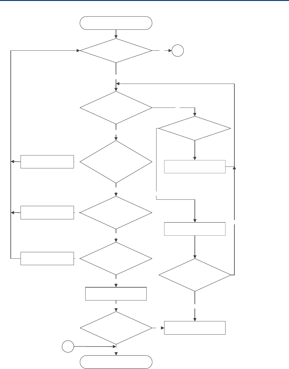
Chapter 11: Troubleshooting Power-up troubleshooting
Page 11-14
Power-up troubleshooting
Module does not power ON
Is the
LED always red?
Is there AC power
going to the supply?
No
Switch ON AC mains power
Test cable, use known
good cable. Could the radio be
in default mode
Yes
Yes
Test cable?
No
Is cable length < 300 meters?
Yes
Connect to a known power
supply
Is the module’s
red L ED ON ?
Yes
Yes
Module is powered ON
Yes
Ethernet cable
repa ired
Contact Cambium Support for
RMA
No
Is Module’s power
LED ON?
No
A
Yes
Cable wire and pin out
corrected
Cable length within
300 meters
Yes
No
No
A
Connect to known good
module
Is module getting
pow ered ON?
No
Yes

Chapter 11: Troubleshooting Registration and connectivity troubleshooting
Page 11-15
Registration and connectivity troubleshooting
SM/BMS Registration
If no SMs are registered to this AP, then the Session Status tab displays the simple message
No
sessions
. In this case, try the following steps.
1 More finely aim the SM or SMs toward the AP.
2 Recheck the Session Status tab of the AP for the presence of LUIDs.
3 If still no LUIDs are reported on the Session Status tab, click the
Configuration
button on the left side of the
Home
page.
RESULT:
The AP responds by opening the AP Configuration page.
4 Click the Radio tab.
5 Find the
Color Code
parameter and note the setting.
6 In the same sequence as you did for the AP directly under
Configuring Link for Test
on Page 5-15, connect the SM to a computing device and to power.
7 On the left side of the SM Home page, click the
Configuration
button.
RESULT:
The Configuration page of the SM opens.
8 Click the Radio tab.
9 If the transmit frequency of the AP is not selected in the
Custom Radio Frequency
Scan Selection List
parameter, select the frequency that matches.
10 If the
Color Code
parameter on this page is not identical to the
Color Code
parameter you noted from the AP, change one of them so that they match.
11 At the bottom of the Radio tab for the SM, click the
Save Changes
button.
12 Click the
Reboot
button.
13 Allow several minutes for the SM to reboot and register to the AP.
14 Return to the computing device that is connected to the AP.
15 Recheck the Session Status tab of the AP for the presence of LUIDs.

Page I
Glossary
Term
Definition
10Base-T Technology in Ethernet communications that can deliver 10 Mb of
data across 328 feet (100 meters) of CAT 5 cable.
169.254.0.0 Gateway IP address default in Cambium fixed wireless broadband IP
network modules.
169.254.1.1 IP address default in Cambium fixed wireless broadband IP network
modules.
255.255.0.0 Subnet mask default in Cambium fixed wireless broadband IP
network modules and in Microsoft and Apple operating systems.
802.3 An IEEE standard that defines the contents of frames that are
transferred through Ethernet connections. Each of these frames
contains a preamble, the address to which the frame is sent, the
address that sends the frame, the length of the data to expect, the
data, and a checksum to validate that no contents were lost.
Access Point Cluster Two to six Access Point Modules that together distribute network or
Internet services to a community of subscribers. Each Access Point
Module covers a 60° or 90° sector. This cluster covers as much as
360°. Also known as AP cluster.
Access Point Module Also known as AP. One module that distributes network or Internet
services in a 60° or 90° sector.
ACT/4 Second-from-left LED in the module. In the operating mode, this
LED is lit when data activity is present on the Ethernet link.
Address Resolution
Protocol
Protocol defined in RFC 826 to allow a network element to correlate
a host IP address to the Ethernet address of the host. See
http://www.faqs.org/rfcs/rfc826.html.
Aggregate Throughput The sum of the throughputs in the uplink and the downlink.
AP Access Point Module. One module that distributes network or
Internet services to subscriber modules.
ARP Address Resolution Protocol. A protocol defined in RFC 826 to allow
a network element to correlate a host IP address to the Ethernet
address of the host. See http://www.faqs.org/rfcs/rfc826.html.
APs MIB
Management Information Base file that defines objects that are
specific to the Access Point Module. See also Management

Chapter 11: Troubleshooting Registration and connectivity troubleshooting
Page II
Term
Definition
Information Base.
ASN.1 Abstract Syntax Notation One language. The format of the text files
that compose the Management Information Base.
Attenuation Reduction of signal strength caused by the travel from the
transmitter to the receiver, and caused by any object between. In
the absence of objects between, a signal that has a short
wavelength experiences a high degree of attenuation nevertheless.
BER Bit Error Rate. The ratio of incorrect data received to correct data
received.
Bit Error Rate Ratio of incorrect data received to correct data received.
Box MIB Management Information Base file that defines module-level
objects. See also Management Information Base.
Bridge Network element that uses the physical address (not the logical
address) of another to pass data. The bridge passes the data to
either the destination address, if found in the simple routing table,
or to all network segments other than the one that transmitted the
data. Modules are Layer 2 bridges except that, where NAT is
enabled for an SM, the SM is a Layer 3 switch. Compare to Switch
and Router, and see also NAT.
Buckets Theoretical data repositories that can be filled at preset rates or
emptied when preset conditions are experienced, such as when
data is transferred.
Burst Preset amount limit of data that may be continuously transferred.
CAT 5 Cable Cable that delivers Ethernet communications from module to
module. Later modules auto-sense whether this cable is wired in a
straight-through or crossover scheme.
CIR Committed Information Rate. For an SM or specified group of SMs,
a level of bandwidth that can be guaranteed to never fall below a
specified minimum (unless oversubscribed). In the Cambium
implementation, this is controlled by the Low Priority Uplink CIR,
Low Priority Downlink CIR, High Priority Uplink CIR, and High
Priority Downlink CIR parameters.
Cluster Management
Module
Module that provides power, GPS timing, and networking
connections for an AP cluster. Also known as CMM4.
CMM Cluster Management Module. A module that provides power, GPS
timing, and networking connections for an Access Point cluster.
CodePoint See DiffServ.
Color Code Field Module parameter that identifies the other modules with which

Chapter 11: Troubleshooting Registration and connectivity troubleshooting
Page III
Term
Definition
communication is allowed. The range of valid values is 0 to 255.
Community String Field Control string that allows a network management station to access
MIB information about the module.
Country Code A parameter that offers multiple fixed selections, each of which
automatically implements frequency band range restrictions for the
selected country. Units shipped to countries other than the United
States must be configured with the corresponding Region Code and
Country Code to comply with local regulatory requirements.
CRCError Field This field displays how many CRC errors occurred on the Ethernet
controller.
Data Encryption Standard Over-the-air link option that uses secret 56-bit keys and 8 parity bits.
Data Encryption Standard (DES) performs a series of bit
permutations, substitutions, and recombination operations on
blocks of data.
Demilitarized Zone Internet Protocol area outside of a firewall. Defined in RFC 2647. See
http://www.faqs.org/rfcs/rfc2647.html.
DES Data Encryption Standard. An over-the-air link option that uses
secret 56-bit keys and 8 parity bits. DES performs a series of bit
permutations, substitutions, and recombination operations on
blocks of data.
DFS See Dynamic Frequency Selection
DHCP Dynamic Host Configuration Protocol, defined in RFC 2131. Protocol
that enables a device to be assigned a new IP address and TCP/IP
parameters, including a default gateway, whenever the device
reboots. Thus DHCP reduces configuration time, conserves IP
addresses, and allows modules to be moved to a different network
within the system. See http://www.faqs.org/rfcs/rfc2131.html. See
also Static IP Address Assignment.
DiffServ Differentiated Services, consistent with RFC 2474. A byte in the type
of service (TOS) field of packets whose values correlates to the
channel on which the packet should be sent. The value is a numeric
code point. Cambium modules map each of 64 code points to
values of 0 through 7. Three of these code points have fixed values,
and the remaining 61 are settable. Values of 0 through 3 map to the
low-priority channel; 4 through 7 to the high-priority channel. The
mappings are the same as 802.1p VLAN priorities. (However,
configuring DiffServ does not automatically enable the VLAN
feature.) Among the settable parameters, the values are set in the
AP for all downlinks within the sector and in the SM for each uplink.

Chapter 11: Troubleshooting Registration and connectivity troubleshooting
Page IV
Term
Definition
DMZ Demilitarized Zone as defined in RFC 2647. An Internet Protocol area
outside of a firewall. See http://www.faqs.org/rfcs/rfc2647.html.
Dynamic Frequency
Selection
A requirement in certain countries and regions for systems to detect
interference from other systems, notably radar systems, and to
avoid co-channel operation with these systems.
Dynamic Host
Configuration Protocol
See DHCP.
Electronic Serial Number Hardware address that the factory assigns to the module for
identification in the Data Link layer interface of the Open Systems
Interconnection system. This address serves as an electronic serial
number. Same as MAC Address.
ESN Electronic Serial Number. The hardware address that the factory
assigns to the module for identification in the Data Link layer
interface of the Open Systems Interconnection system. This address
serves as an electronic serial number. Same as MAC Address.
Ethernet Protocol Any of several IEEE standards that define the contents of frames
that are transferred from one network element to another through
Ethernet connections.
ETSI European Telecommunications Standards Institute
Fade Margin The difference between strength of the received signal and the
strength that the receiver requires for maintaining a reliable link. A
higher fade margin is characteristic of a more reliable link. Standard
operating margin.
FCC Federal Communications Commission of the U.S.A.
Field-programmable Gate
Array
Array of logic, relational data, and wiring data that is factory
programmed and can be reprogrammed.
File Transfer Protocol Utility that transfers of files through TCP (Transport Control
Protocol) between computing devices that do not operate on the
same platform. Defined in RFC 959. See
http://www.faqs.org/rfcs/rfc959.html.
FPGA Field-programmable Gate Array. An array of logic, relational data,
and wiring data that is factory programmed and can be
reprogrammed.
Free Space Path Loss Signal attenuation that is naturally caused by atmospheric
conditions and by the distance between the antenna and the
receiver.
Fresnel Zone Space in which no object should exist that can attenuate, diffract, or
reflect a transmitted signal before the signal reaches the target

Chapter 11: Troubleshooting Registration and connectivity troubleshooting
Page V
Term
Definition
receiver.
FTP File Transfer Protocol, defined in RFC 959. Utility that transfers of
files through TCP (Transport Control Protocol) between computing
devices that do not operate on the same platform. See
http://www.faqs.org/rfcs/rfc959.html.
Global Positioning
System
Network of satellites that provides absolute time to networks on
earth, which use the time signal to synchronize transmission and
reception cycles (to avoid interference) and to provide reference for
troubleshooting activities.
GPS Global Positioning System. A network of satellites that provides
absolute time to networks on earth, which use the time signal to
synchronize transmission and reception cycles (to avoid
interference) and to provide reference for troubleshooting activities.
GPS/3 Third-from-left LED in the module. In the operating mode for an
Access Point Module, this LED is continuously lit as the module
receives sync pulse. In the operating mode for a Subscriber, this
LED flashes on and off to indicate that the module is not registered.
GUI Graphical user interface.
High-priority Channel Channel that supports low-latency traffic (such as Voice over IP)
over low-latency traffic (such as standard web traffic and file
downloads). To recognize the latency tolerance of traffic, this
channel reads the IPv4 Type of Service DiffServ Control Point
(DSCP) bits. Enabling the high-priority channel reduces the
maximum number of SMs that can be served in the sector.
HTTP Hypertext Transfer Protocol, used to make the Internet resources
available on the World Wide Web. Defined in RFC 2068. See
http://www.faqs.org/rfcs/rfc2068.html.
HTTPS Hypertext Transfer Protocol Secure (HTTPS)
ICMP Internet Control Message Protocols defined in RFC 792, used to
identify Internet Protocol (IP)-level problems and to allow IP links to
be tested. See http://www.faqs.org/rfcs/rfc792.html.
IP Internet Protocol defined in RFC 791. The Network Layer in the
TCP/IP protocol stack. This protocol is applied to addressing,
routing, and delivering, and re-assembling data packets into the
Data Link layer of the protocol stack. See
http://www.faqs.org/rfcs/rfc791.html.
IP Address 32-bit binary number that identifies a network element by both
network and host. See also Subnet Mask.

Chapter 11: Troubleshooting Registration and connectivity troubleshooting
Page VI
Term
Definition
IPv4 Traditional version of Internet Protocol, which defines 32-bit fields
for data transmission.
ISM Industrial, Scientific, and Medical Equipment radio frequency band,
in the 900-MHz, 2.4-GHz, and 5.8-GHz ranges.
L2TP over IPSec Level 2 Tunneling Protocol over IP Security. One of several virtual
private network (VPN) implementation schemes. Regardless of
whether Subscriber Modules have the Network Address Translation
feature (NAT) enabled, they support VPNs that are based on this
protocol.
Late Collision Field This field displays how many late collisions occurred on the
Ethernet controller. A normal collision occurs during the first 512
bits of the frame transmission. A collision that occurs after the first
512 bits is considered a late collision. A late collision is a serious
network problem because the frame being transmitted is discarded.
A late collision is most commonly caused by a mismatch between
duplex configurations at the ends of a link segment.
Line of Sight Wireless path (not simply visual path) direct from module to
module. The path that results provides both ideal aim and an ideal
Fresnel zone.
LNK/5 Furthest left LED in the module. In the operating mode, this LED is
continuously lit when the Ethernet link is present. In the aiming
mode for a Subscriber Module, this LED is part of a bar graph that
indicates the quality of the RF link.
Logical Unit ID Final octet of the 4-octet IP address of the module.
LOS Line of sight. The wireless path (not simply visual path) direct from
module to module. The path that results provides both ideal aim
and an ideal Fresnel zone.
LUID Logical Unit ID. The final octet of the 4-octet IP address of the
module.
MAC Address Media Access Control address. The hardware address that the
factory assigns to the module for identification in the Data Link layer
interface of the Open Systems Interconnection system. This address
serves as an electronic serial number.
Management Information
Base
Space that allows a program (agent) in the network to relay
information to a network monitor about the status of defined
variables (objects).
Maximum Information
Rate (MIR)
The cap applied to the bandwidth of an SM or specified group of
SMs. In the Cambium implementation, this is controlled by the
Sustained Uplink Data Rate, Uplink Burst Allocation, Sustained

Chapter 11: Troubleshooting Registration and connectivity troubleshooting
Page VII
Term
Definition
Downlink Data Rate, and Downlink Burst Allocation parameters.
MIB Management Information Base. Space that allows a program
(agent) in the network to relay information to a network monitor
about the status of defined variables (objects).
MIR See Maximum Information Rate.
NAT Network Address Translation defined in RFC 1631. A scheme that
isolates Subscriber Modules from the Internet. See
http://www.faqs.org/rfcs/rfc1631.html.
NEC National Electrical Code. The set of national wiring standards that
are enforced in the U.S.A.
NetBIOS Protocol defined in RFC 1001 and RFC 1002 to support an
applications programming interface in TCP/IP. This interface allows
a computer to transmit and receive data with another host computer
on the network. RFC 1001 defines the concepts and methods. RFC
1002 defines the detailed specifications. See
http://www.faqs.org/rfcs/rfc1001.html and
http://www.faqs.org/rfcs/rfc1002.html.
Network Address
Translation
Scheme that defines the Access Point Module as a proxy server to
isolate registered Subscriber Modules from the Internet. Defined in
RFC 1631. See http://www.faqs.org/rfcs/rfc1631.html.
Network Management
Station
See NMS.
NMS Network Management Station. A monitor device that uses Simple
Network Management Protocol (SNMP) to control, gather, and
report information about predefined network variables (objects).
See also Simple Network Management Protocol.
PMP See Point-to-Multipoint Protocol.
Point-to-Multipoint
Protocol
Defined in RFC 2178, which specifies that data that originates from a
central network element can be received by all other network
elements, but data that originates from a non-central network
element can be received by only the central network element. See
http://www.faqs.org/rfcs/rfc2178.html. Also referenced as PMP.
PPPoE Point to Point Protocol over Ethernet. Supported on SMs for
operators who use PPPoE in other parts of their network
operators who want to deploy PPPoE to realize per-subscriber
authentication, metrics, and usage control.
PPS Packet Per Second
PPTP Point to Point Tunneling Protocol. One of several virtual private

Chapter 11: Troubleshooting Registration and connectivity troubleshooting
Page VIII
Term
Definition
network implementations. Regardless of whether the Network
Address Translation (NAT) feature enabled, Subscriber Modules
support VPNs that are based on this protocol.
Protective Earth Connection to earth (which has a charge of 0 volts). Also known as
ground.
Proxy Server Network computer that isolates another from the Internet. The
proxy server communicates for the other computer, and sends
replies to only the appropriate computer, which has an IP address
that is not unique or not registered.
Radio Signal Strength
Indicator
Relative measure of the strength of a received signal. An acceptable
link displays a Radio Signal Strength Indicator (RSSI) value of
greater than 700.
Reflection Change of direction and reduction of amplitude of a signal that
encounters an object larger than the wavelength. Reflection may
cause an additional copy of the wavelength to arrive after the
original, unobstructed wavelength arrives. This causes partial
cancellation of the signal and may render the link unacceptable.
However, in some instances where the direct signal cannot be
received, the reflected copy may be received and render an
otherwise unacceptable link acceptable.
Region Code A parameter that offers multiple fixed selections, each of which
automatically implements frequency band range restrictions for the
selected region. Units shipped to regions other than the United
States must be configured with the corresponding Region Code to
comply with local regulatory requirements.
RF Radio frequency. How many times each second a cycle in the
antenna occurs, from positive to negative and back to positive
amplitude.
RJ-12 Standard cable that is typically used for telephone line or modem
connection.
RJ-45 Standard cable that is typically used for Ethernet connection. This
cable may be wired as straight-through or as crossover. Later
modules auto-sense whether the cable is straight-through or
crossover.
Router Network element that uses the logical (IP) address of another to
pass data to only the intended recipient. Compare to Switch and
Bridge.
RSSI Radio Signal Strength Indicator. A relative measure of the strength
of a received signal. An acceptable link displays an RSSI value of

Chapter 11: Troubleshooting Registration and connectivity troubleshooting
Page IX
Term
Definition
greater than 700.
Self-interference Interference with a module from another module in the same
network.
Simple Network
Management Protocol
Standard that is used for communications between a program
(agent) in the network and a network management station
(monitor). Defined in RFC 1157. See
http://www.faqs.org/rfcs/rfc1157.html.
SM Customer premises equipment (CPE) device that extends network or
Internet services by communication with an Access Point Module or
an Access Point cluster.
SNMP See Simple Network Management Protocol, defined in RFC 1157.
SNMPv3 SNMP version 3
SNMP Trap Capture of information that informs the network monitor through
Simple Network Management Protocol of a monitored occurrence in
the module.
Static IP Address
Assignment
Assignment of Internet Protocol address that can be changed only
manually. Thus static IP address assignment requires more
configuration time and consumes more of the available IP
addresses than DHCP address assignment does. RFC 2050 provides
guidelines for the static allocation of IP addresses. See
http://www.faqs.org/rfcs/rfc2050.html. See also DHCP.
Subnet Mask 32-bit binary number that filters an IP address to reveal what part
identifies the network and what part identifies the host. The number
of subnet mask bits that are set to 1 indicates how many leading
bits of the IP address identify the network. The number of subnet
mask bits that are set 0 indicate how many trailing bits of the IP
address identify the host.
Subscriber Module Customer premises equipment (CPE) device that extends network or
Internet services by communication with an Access Point Module or
an Access Point cluster.
Sustained Data Rate Preset rate limit of data transfer.
Switch Network element that uses the port that is associated with the
physical address of another to pass data to only the intended
recipient. Compare to Bridge and Router.
Sync GPS (Global Positioning System) absolute time, which is passed
from one module to another. Sync enables timing that prevents
modules from transmitting or receiving interference. Sync also
provides correlative time stamps for troubleshooting efforts.

Chapter 11: Troubleshooting Registration and connectivity troubleshooting
Page X
Term
Definition
TCP Alternatively known as Transmission Control Protocol or Transport
Control Protocol. The Transport Layer in the TCP/IP protocol stack.
This protocol is applied to assure that data packets arrive at the
target network element and to control the flow of data through the
Internet. Defined in RFC 793. See
http://www.faqs.org/rfcs/rfc793.html.
TDD Time Division Duplexing. Synchronized data transmission with
some time slots allocated to devices transmitting on the uplink and
some to the device transmitting on the downlink.
telnet Utility that allows a client computer to update a server. A firewall
can prevent the use of the telnet utility to breach the security of the
server. See http://www.faqs.org/rfcs/rfc818.html,
http://www.faqs.org/rfcs/rfc854.html and
http://www.faqs.org/rfcs/rfc855.html.
Tokens Theoretical amounts of data. See also Buckets.
TxUnderrun Field This field displays how many transmission-underrun errors
occurred on the Ethernet controller.
UDP User Datagram Protocol. A set of Network, Transport, and Session
Layer protocols that RFC 768 defines. These protocols include
checksum and address information but does not retransmit data or
process any errors. See http://www.faqs.org/rfcs/rfc768.html.
udp User-defined type of port.
U-NII Unlicensed National Information Infrastructure radio frequency
band, in the 5.1-GHz through 5.8-GHz ranges.
VID VLAN identifier. See also VLAN.
VLAN Virtual local area network. An association of devices through
software that contains broadcast traffic, as routers would, but in the
switch-level protocol.
VPN Virtual private network for communication over a public network.
One typical use is to connect remote employees, who are at home
or in a different city, to their corporate network over the Internet.
Any of several VPN implementation schemes is possible. SMs
support L2TP over IPSec (Level 2 Tunneling Protocol over IP
Security) VPNs and PPTP (Point to Point Tunneling Protocol) VPNs,
regardless of whether the Network Address Translation (NAT)
feature enabled.