Cambium Networks 50450M 5GHz Point to MultiPoint Multi User MIMO Access Point User Manual USERS MANUAL PART1
Cambium Networks Limited 5GHz Point to MultiPoint Multi User MIMO Access Point USERS MANUAL PART1
Contents
- 1. USER GUIDE P1
- 2. USER GUIDE P2
- 3. USER GUIDE P3
- 4. USER GUIDE P4
- 5. User manual
- 6. User Manual
- 7. USERS MANUAL PART1
- 8. USERS MANUAL PART2
- 9. USERS MANUAL PART3
- 10. USERS MANUAL PART4
- 11. USER MANUAL PART1
- 12. USER MANUAL PART2
- 13. USER MANUAL PART 3
- 14. USER MANUAL PART 4
- 15. USER MANUAL PT1
- 16. USER MANUAL PT2
- 17. USER MANUAL PT3
USERS MANUAL PART1
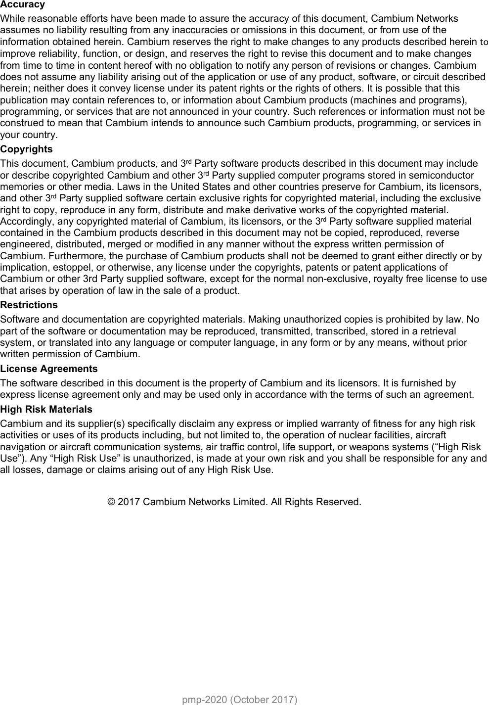


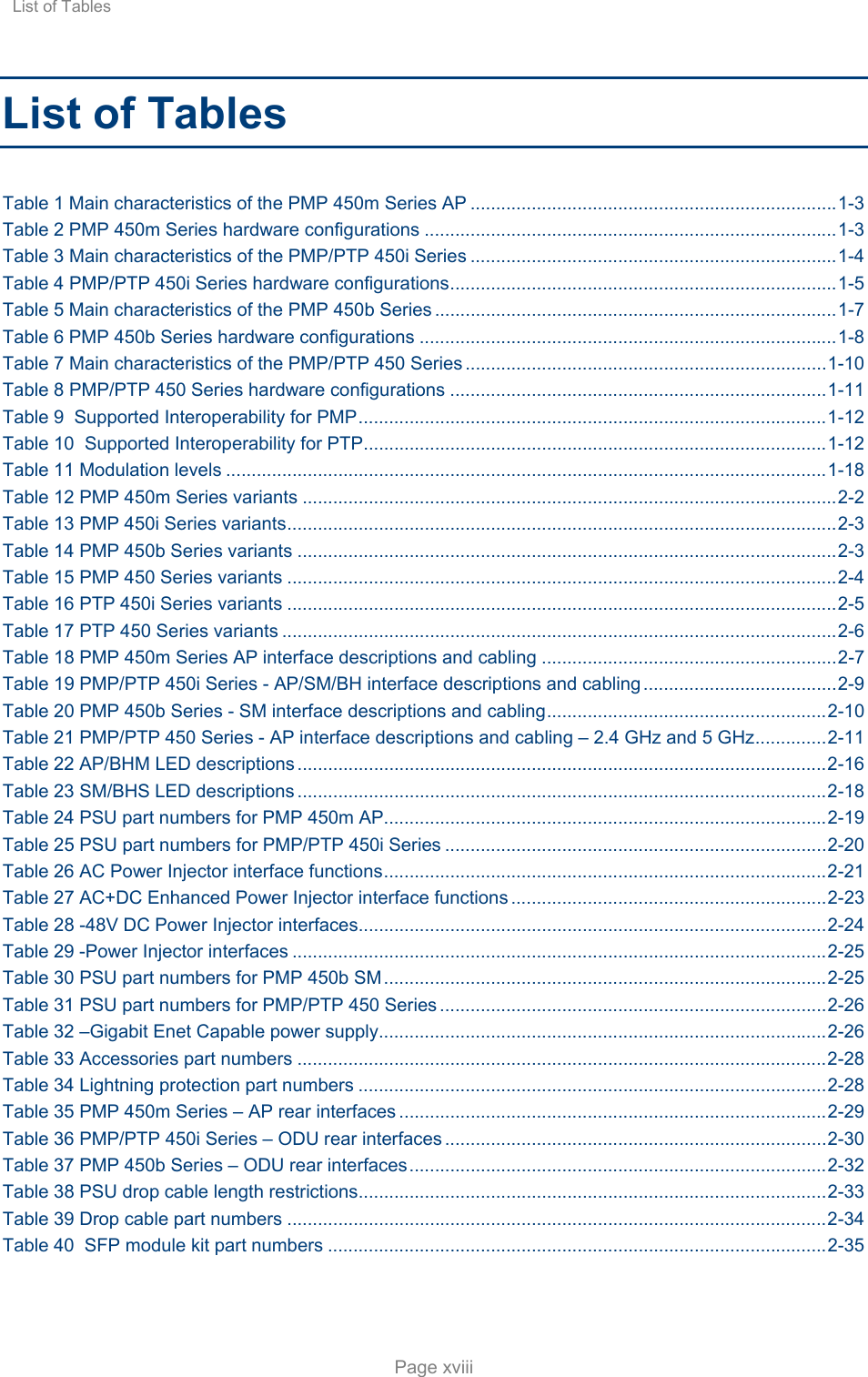
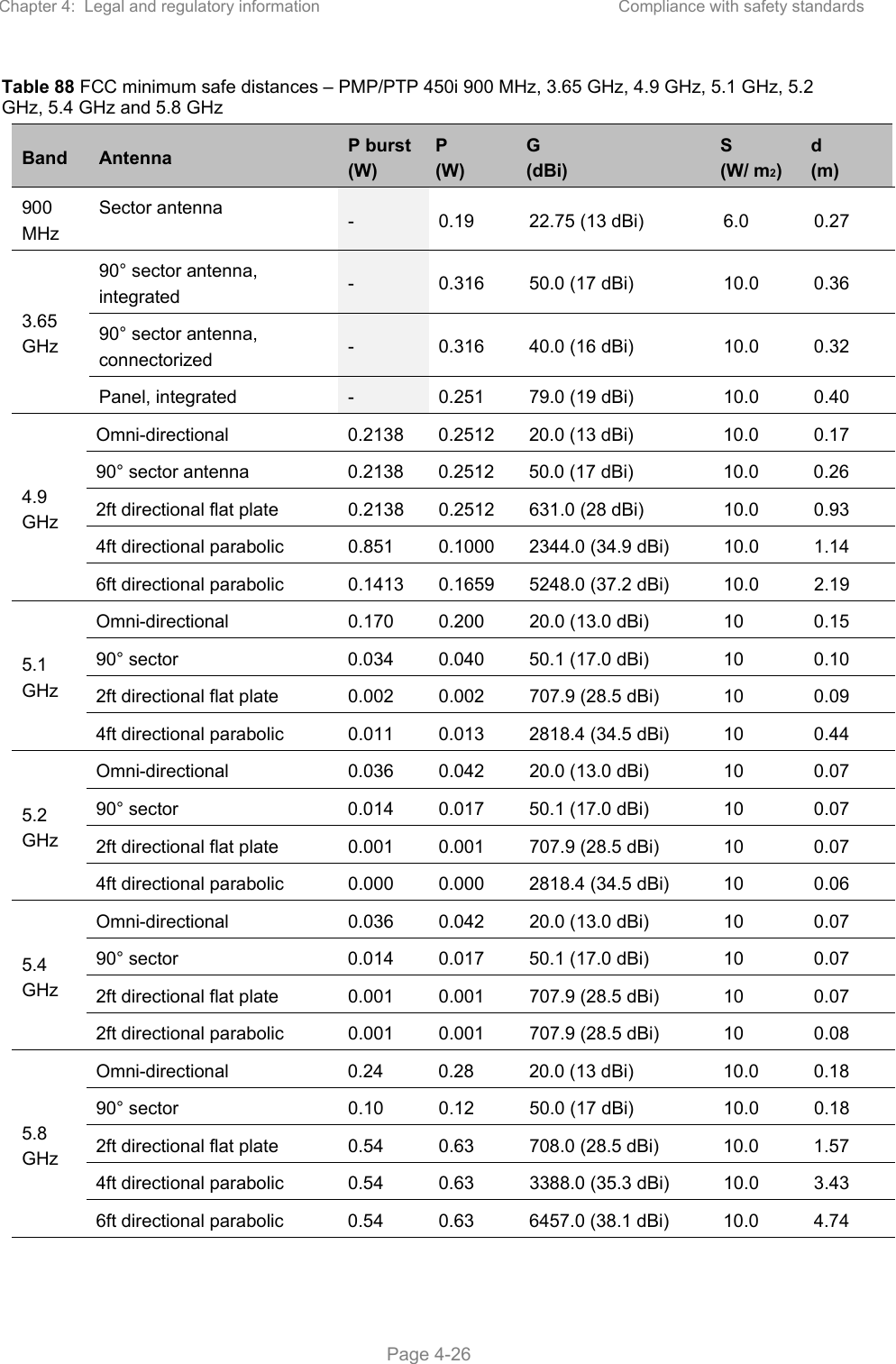
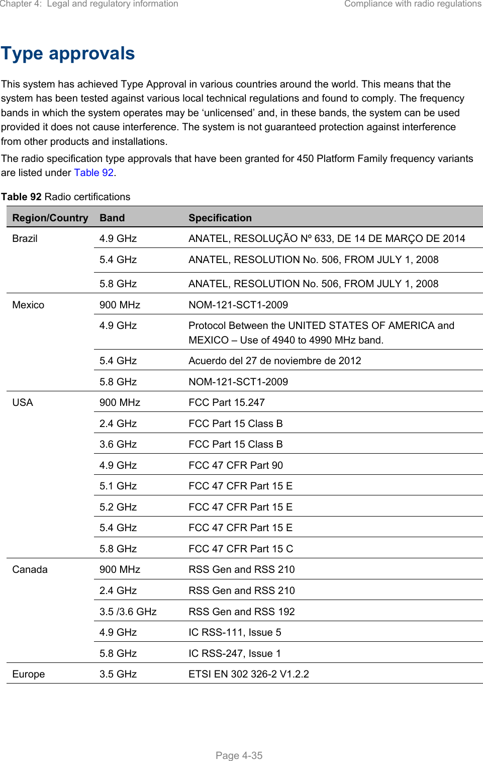
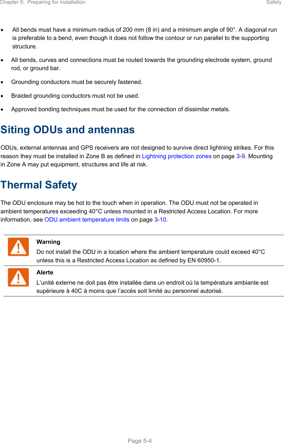
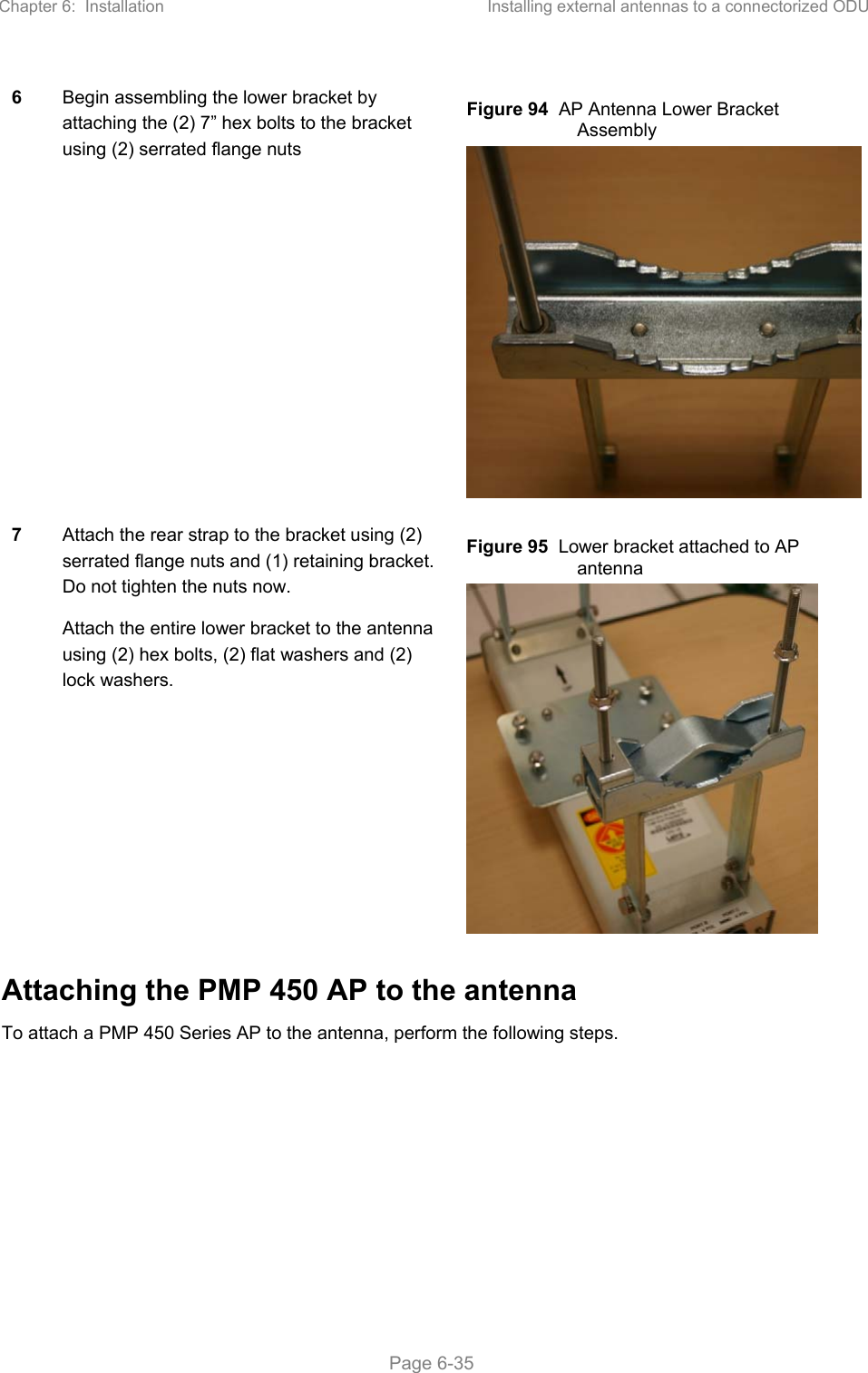
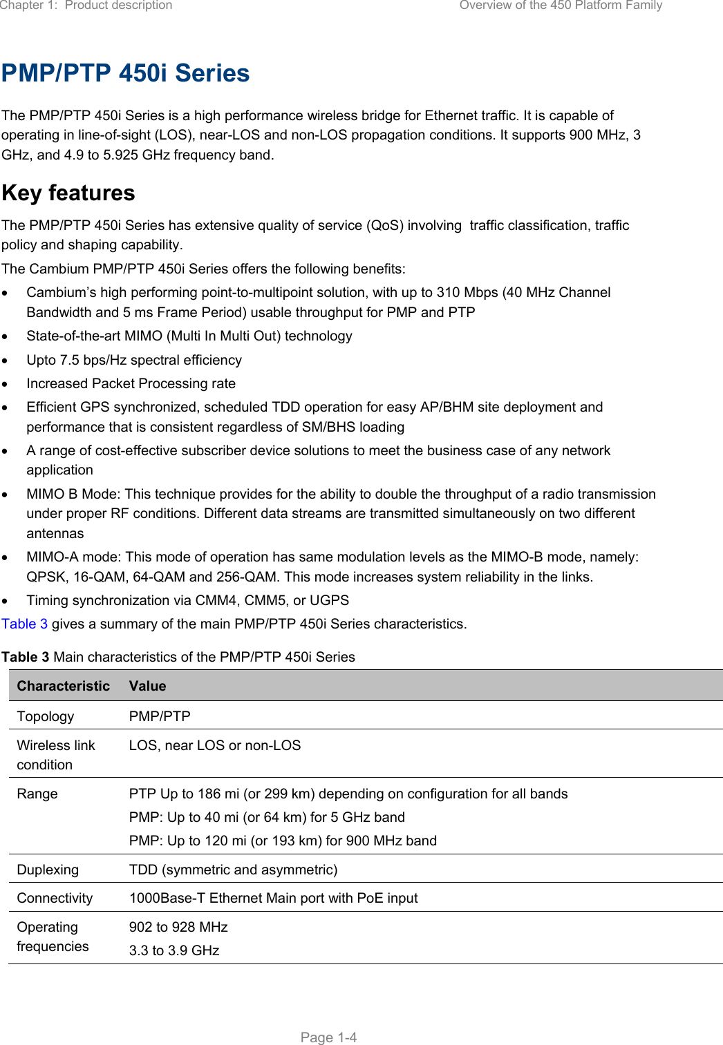
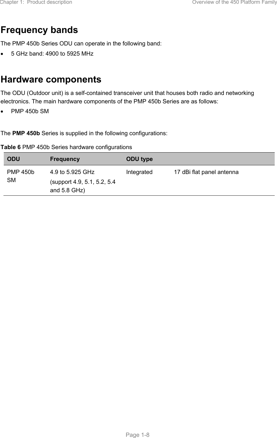
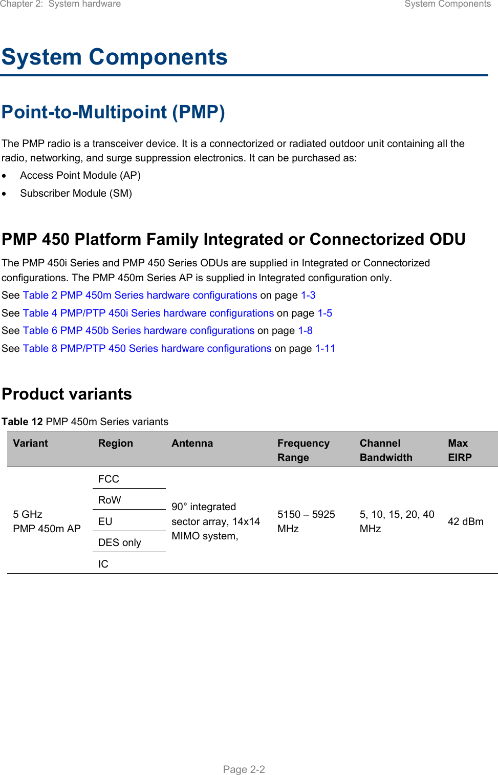
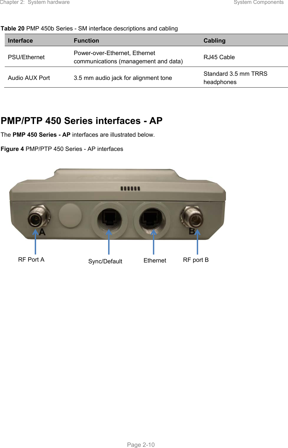
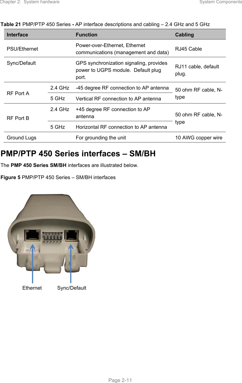
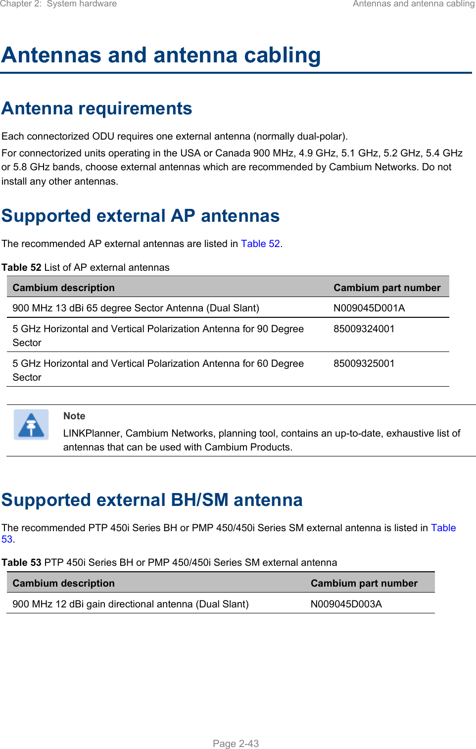
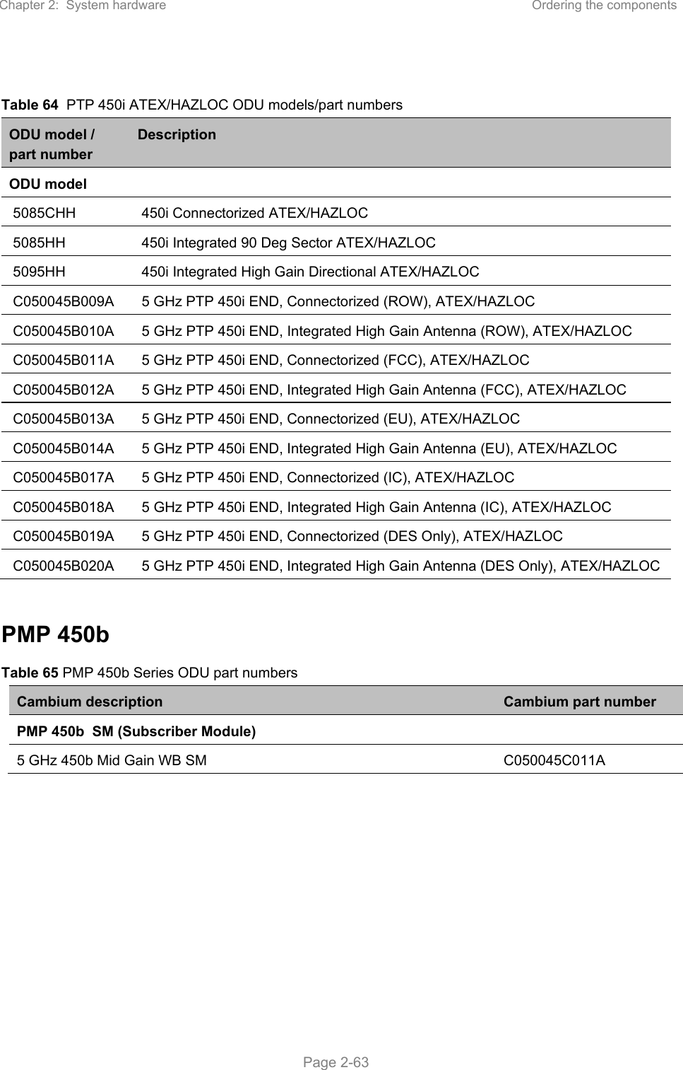
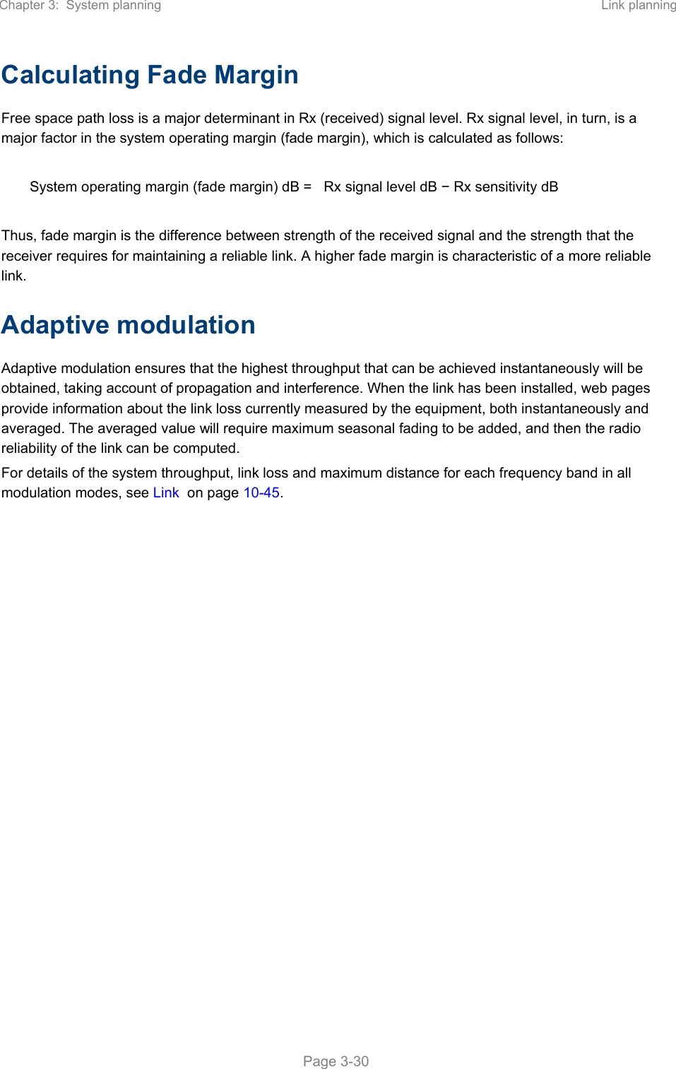
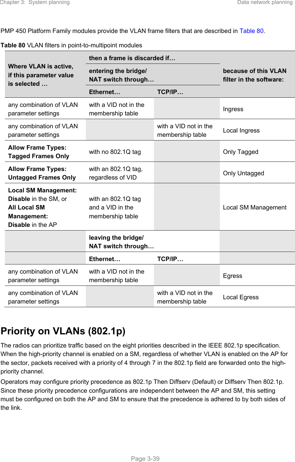
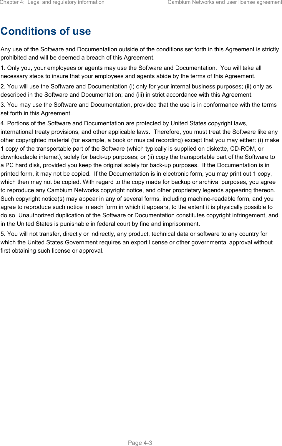
![Page 2 Purpose Cambium Networks Point-to-Multi-Point (PMP)/Point-To-Point (PTP) 450 documents are intended to instruct and assist personnel in the operation, installation and maintenance of the Cambium PMP/PTP equipment and ancillary devices of 450 Platform Family. It is recommended that all personnel engaged in such activities be properly trained. Cambium disclaims all liability whatsoever, implied or express, for any risk of damage, loss or reduction in system performance arising directly or indirectly out of the failure of the customer, or anyone acting on the customer's behalf, to abide by the instructions, system parameters, or recommendations made in this document. Product notation conventions in document This document covers Cambium 450 Series, 450i Series and 450m Series products. The following notation conventions are followed while referring to product series and product family: Product notation Description 450 Platform Family Refers to the complete 450 Series family, which includes 450 Series, 450i Series and 450m Series 450 Series Refers to 450 Series devices in the following configurations: - PMP 450 - AP [2.4GHz/3.5 GHz/3.65 GHz /5 GHz] - Connectorized - SM [900 MHz/2.4GHz/3.5 GHz/3.65 GHz /5 GHz] - Connectorized/ Integrated - PTP 450 BHM/ BHS [900 MHz/3.5 GHz/3.65 GHz/5 GHz] - Connectorized/ Integrated - PMP 450d SM [5 GHz] 450i Series Refers to 450i Series devices in the following configurations: - PMP 450i - AP [900 MHz/3 GHz/5 GHz] - Connectorized/ Integrated - SM [3 GHz/5 GHz] - Connectorized/ Integrated - PTP 450i BHM/ BHS [3 GHz/5 GHz] - Connectorized/ Integrated 450b Series Refers to 450b Series devices in the following configurations: - PMP 450b - SM [5 GHz] - Integrated](https://usermanual.wiki/Cambium-Networks/50450M.USERS-MANUAL-PART1/User-Guide-3650829-Page-28.png)


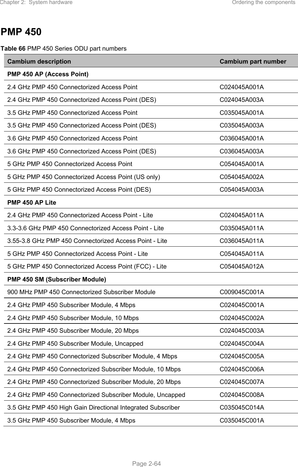

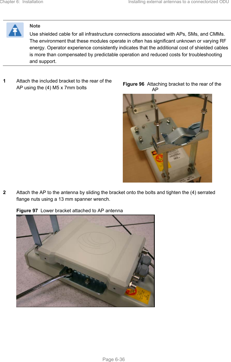
![Chapter 4: Legal and regulatory information Cambium Networks end user license agreement Page 4-13 If this package is used in a product, Eric Young should be given attribution as the author of the parts of the library used. This can be in the form of a textual message at program startup or in documentation (online or textual) provided with the package. Redistribution and use in source and binary forms, with or without modification, are permitted provided that the following conditions are met: 1. Redistributions of source code must retain the copyright notice, this list of conditions and the following disclaimer. 2. Redistributions in binary form must reproduce the above copyright notice, this list of conditions and the following disclaimer in the documentation and/or other materials provided with the distribution. 3. All advertising materials mentioning features or use of this software must display the following acknowledgement: “This product includes cryptographic software written by Eric Young (eay@cryptsoft.com)” The word ‘cryptographic’ can be left out if the routines from the library being used are not cryptographic related. 4. If you include any Windows specific code (or a derivative thereof) from the apps directory (application code) you must include an acknowledgement: “This product includes software written by Tim Hudson (tjh@cryptsoft.com)” THIS SOFTWARE IS PROVIDED BY ERIC YOUNG “AS IS” AND ANY EXPRESS OR IMPLIED WARRANTIES, INCLUDING, BUT NOT LIMITED TO, THE IMPLIED WARRANTIES OF MERCHANTABILITY AND FITNESS FOR A PARTICULAR PURPOSE ARE DISCLAIMED. IN NO EVENT SHALL THE AUTHOR OR CONTRIBUTORS BE LIABLE FOR ANY DIRECT, INDIRECT, INCIDENTAL, SPECIAL, EXEMPLARY, OR CONSEQUENTIAL DAMAGES (INCLUDING, BUT NOT LIMITED TO, PROCUREMENT OF SUBSTITUTE GOODS OR SERVICES; LOSS OF USE, DATA, OR PROFITS; OR BUSINESS INTERRUPTION) HOWEVER CAUSED AND ON ANY THEORY OF LIABILITY, WHETHER IN CONTRACT, STRICT LIABILITY, OR TORT (INCLUDING NEGLIGENCE OR OTHERWISE) ARISING IN ANY WAY OUT OF THE USE OF THIS SOFTWARE, EVEN IF ADVISED OF THE POSSIBILITY OF SUCH DAMAGE. The license and distribution terms for any publically available version or derivative of this code cannot be changed. i.e. this code cannot simply be copied and put under another distribution license [including the GNU Public License.] Zlib Copyright © 1995-2005 Jean-loup Gailly and Mark Adler This software is provided ‘as-is’, without any express or implied warranty. In no event will the authors be held liable for any damages arising from the use of this software. Permission is granted to anyone to use this software for any purpose, including commercial applications, and to alter it and redistribute it freely, subject to the following restrictions: 1. The origin of this software must not be misrepresented; you must not claim that you wrote the original software. If you use this software in a product, an acknowledgment in the product documentation would be appreciated but is not required. 2. Altered source versions must be plainly marked as such, and must not be misrepresented as being the original software.](https://usermanual.wiki/Cambium-Networks/50450M.USERS-MANUAL-PART1/User-Guide-3650829-Page-206.png)

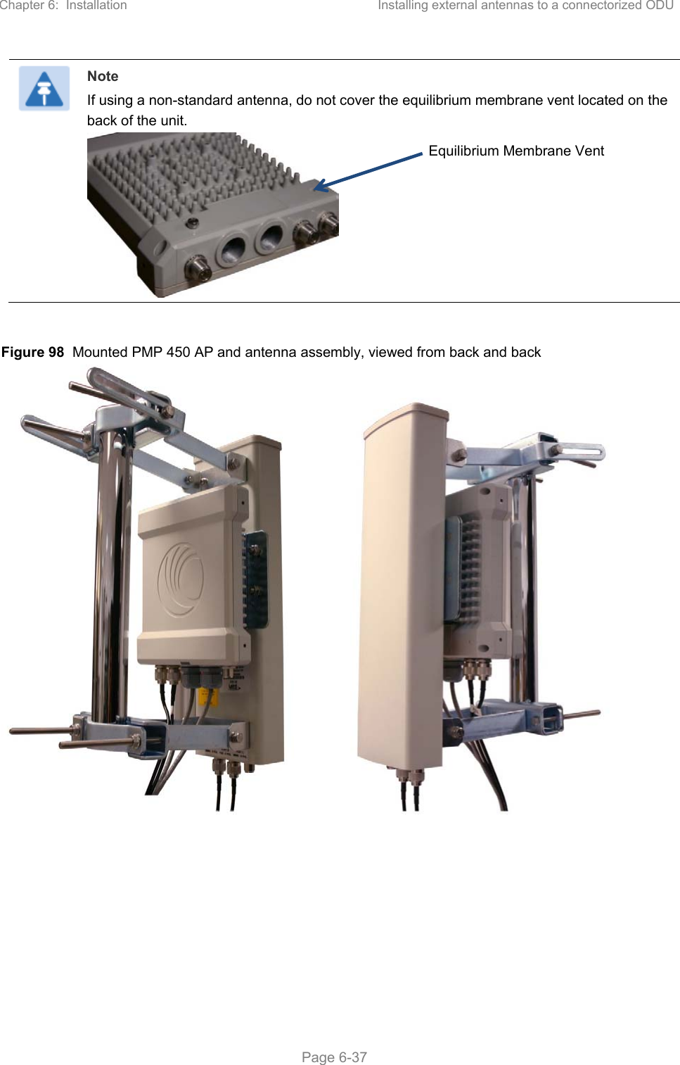
![Chapter 4: Legal and regulatory information Cambium Networks end user license agreement Page 4-20 License. However, in accepting such obligations, You may act only on Your own behalf and on Your sole responsibility, not on behalf of any other Contributor, and only if You agree to indemnify, defend, and hold each Contributor harmless for any liability incurred by, or claims asserted against, such Contributor by reason of your accepting any such warranty or additional liability. END OF TERMS AND CONDITIONS APPENDIX: How to apply the Apache License to your work. To apply the Apache License to your work, attach the following boilerplate notice, with the fields enclosed by brackets "[]" replaced with your own identifying information. (Don't include the brackets!) The text should be enclosed in the appropriate comment syntax for the file format. We also recommend that a file or class name and description of purpose be included on the same "printed page" as the copyright notice for easier identification within third-party archives. Copyright [yyyy] [name of copyright owner] Licensed under the Apache License, Version 2.0 (the "License"); you may not use this file except in compliance with the License. You may obtain a copy of the License at http://www.apache.org/licenses/LICENSE-2.0 Unless required by applicable law or agreed to in writing, software distributed under the License is distributed on an "AS IS" BASIS, WITHOUT WARRANTIES OR CONDITIONS OF ANY KIND, either express or implied. See the License for the specific language governing permissions and limitations under the License.](https://usermanual.wiki/Cambium-Networks/50450M.USERS-MANUAL-PART1/User-Guide-3650829-Page-213.png)