Cambium Networks 50450M 5GHz Point to MultiPoint Multi User MIMO Access Point User Manual USERS MANUAL PART2
Cambium Networks Limited 5GHz Point to MultiPoint Multi User MIMO Access Point USERS MANUAL PART2
Contents
- 1. USER GUIDE P1
- 2. USER GUIDE P2
- 3. USER GUIDE P3
- 4. USER GUIDE P4
- 5. User manual
- 6. User Manual
- 7. USERS MANUAL PART1
- 8. USERS MANUAL PART2
- 9. USERS MANUAL PART3
- 10. USERS MANUAL PART4
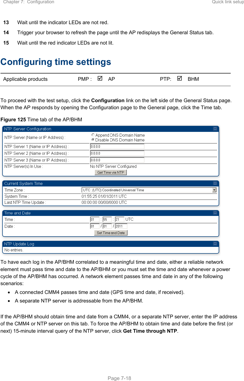
- 11. USER MANUAL PART1
- 12. USER MANUAL PART2
- 13. USER MANUAL PART 3
- 14. USER MANUAL PART 4
- 15. USER MANUAL PT1
- 16. USER MANUAL PT2
- 17. USER MANUAL PT3
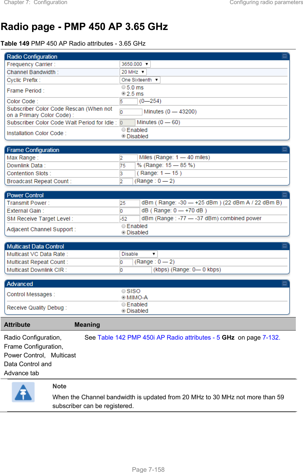
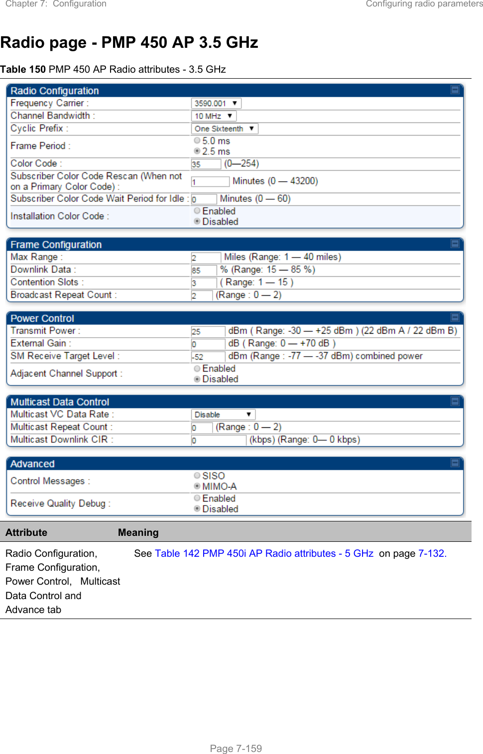
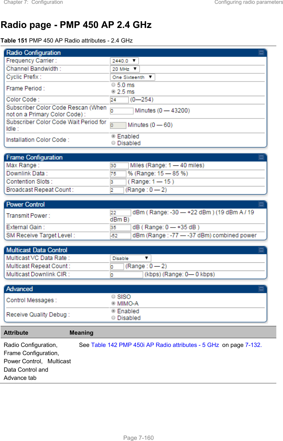
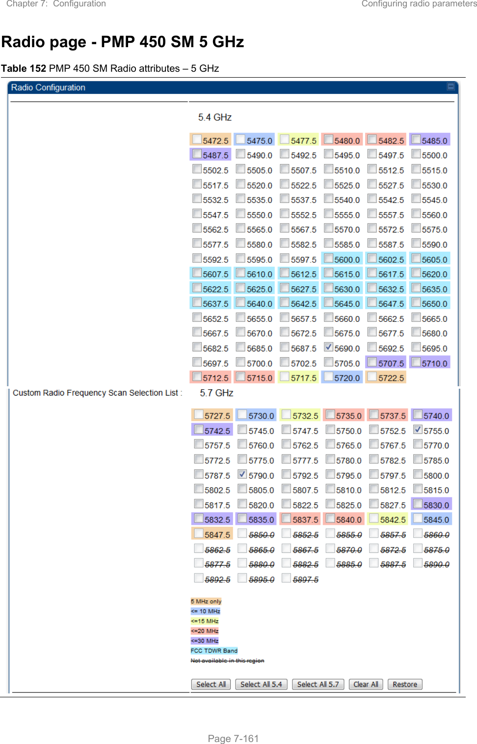
USERS MANUAL PART2
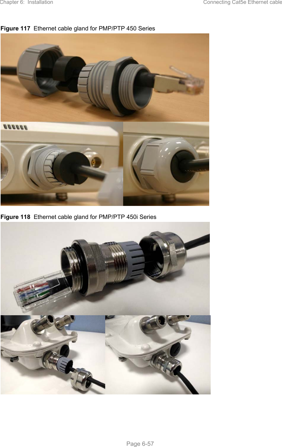
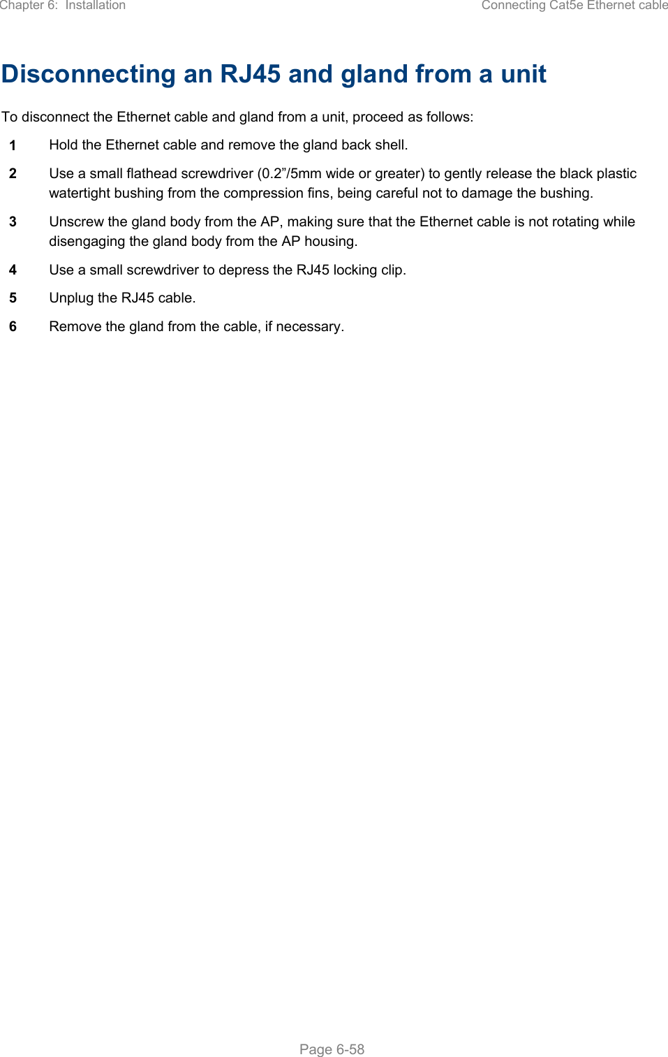
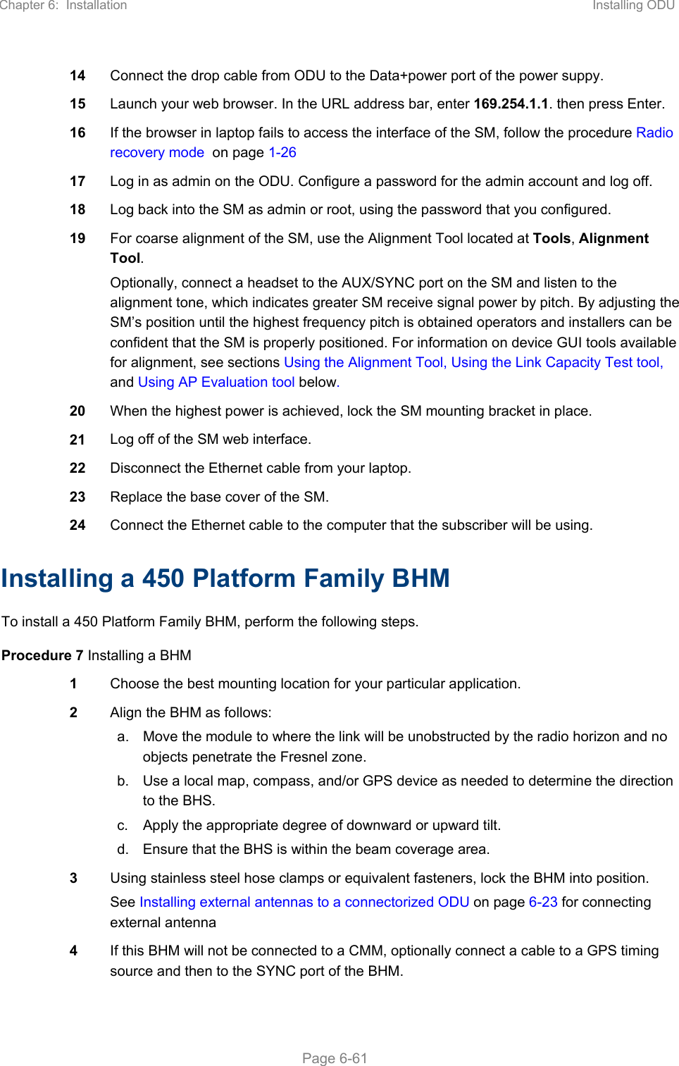
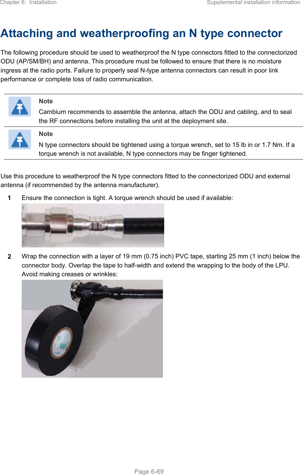
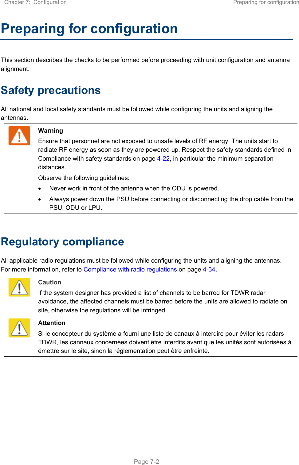
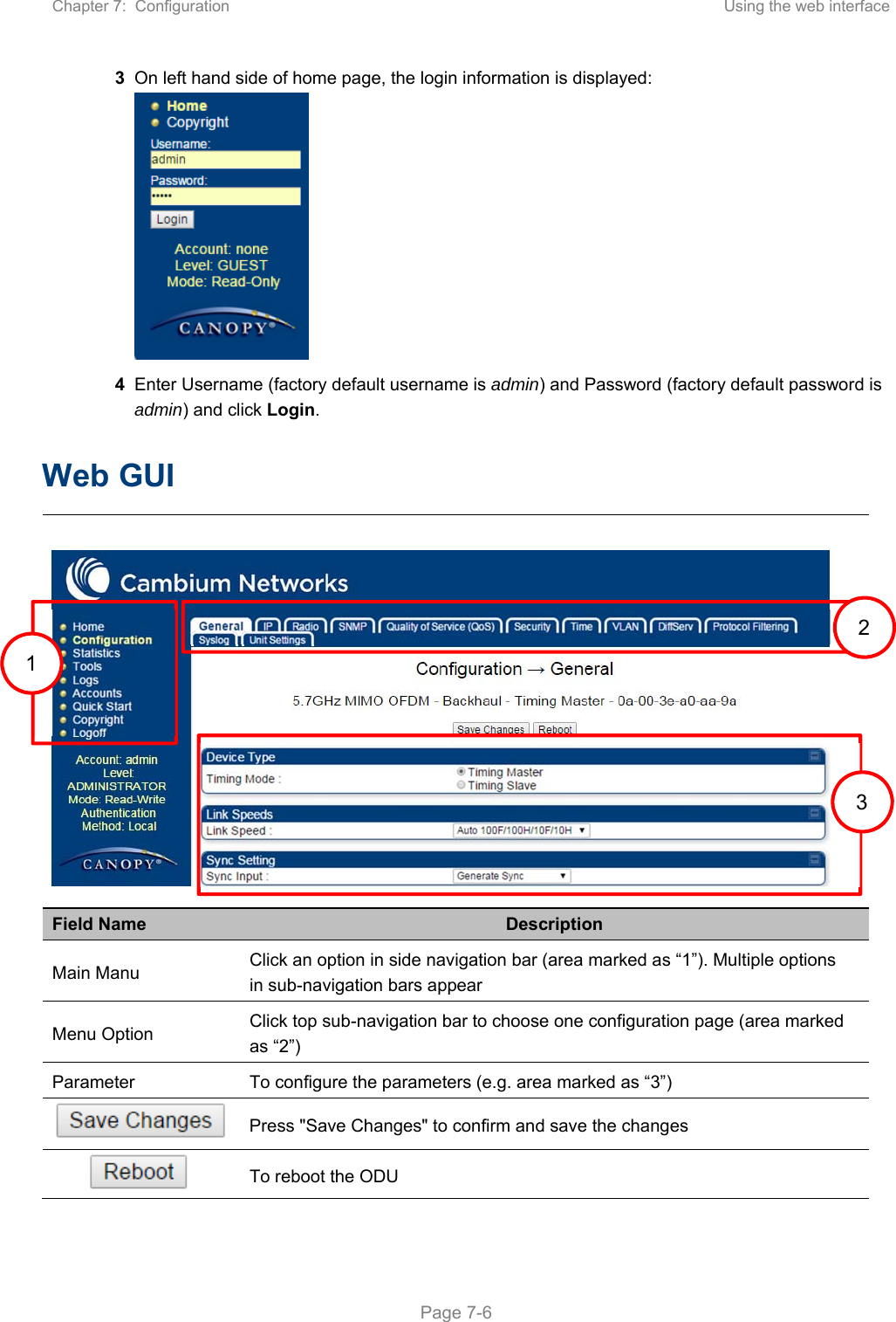
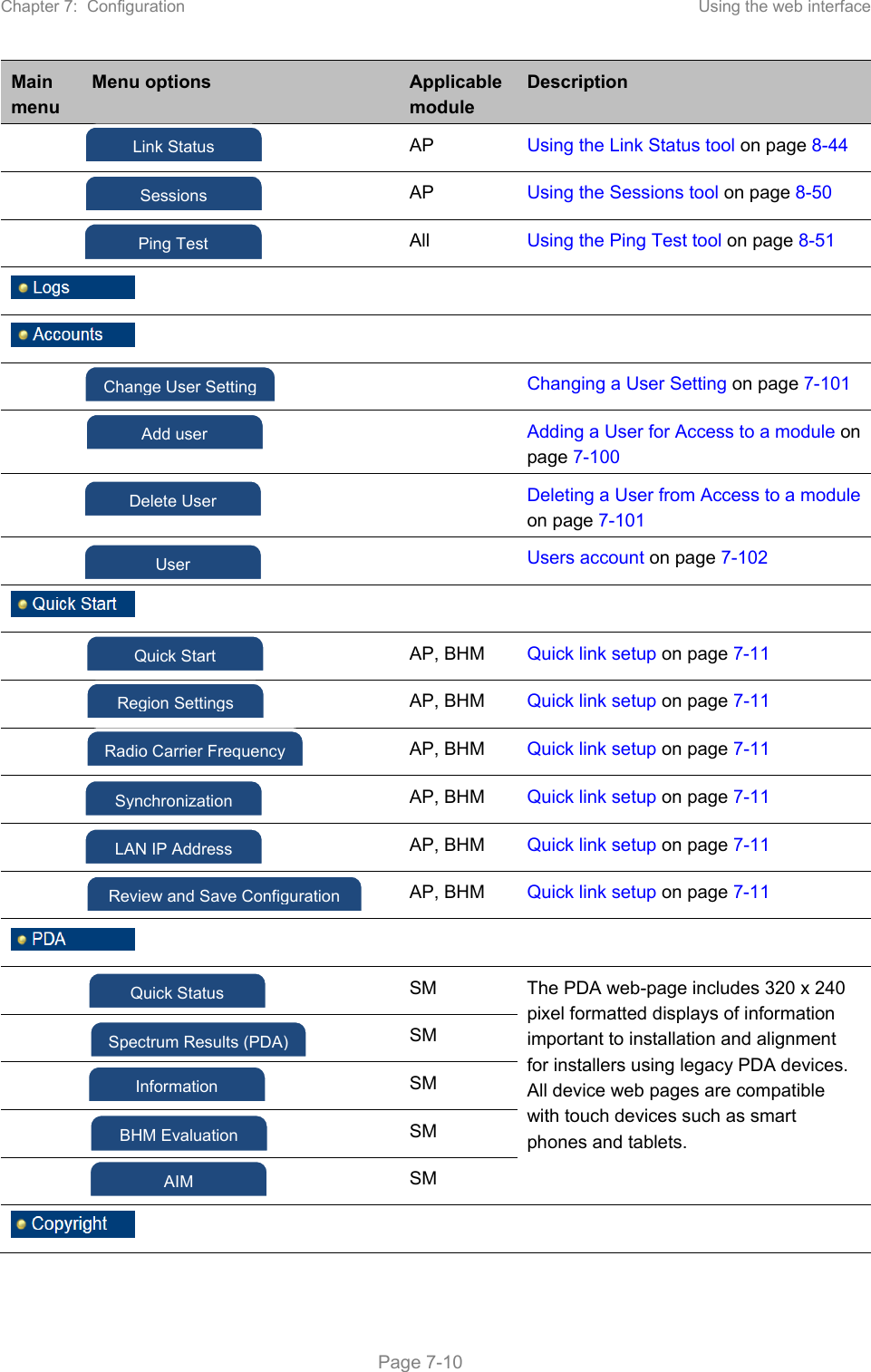
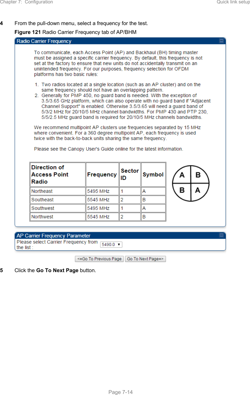
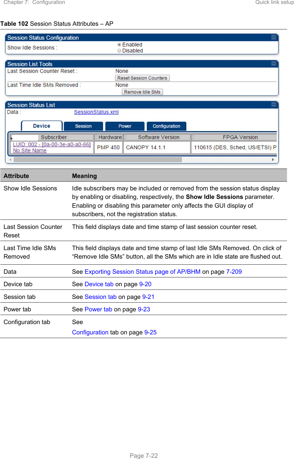
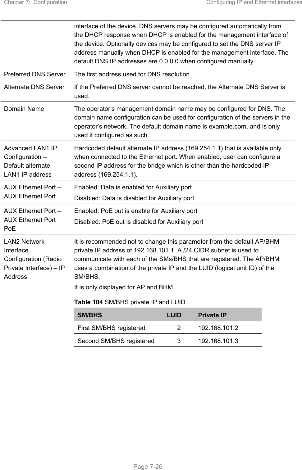
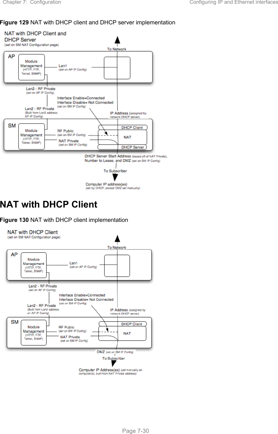
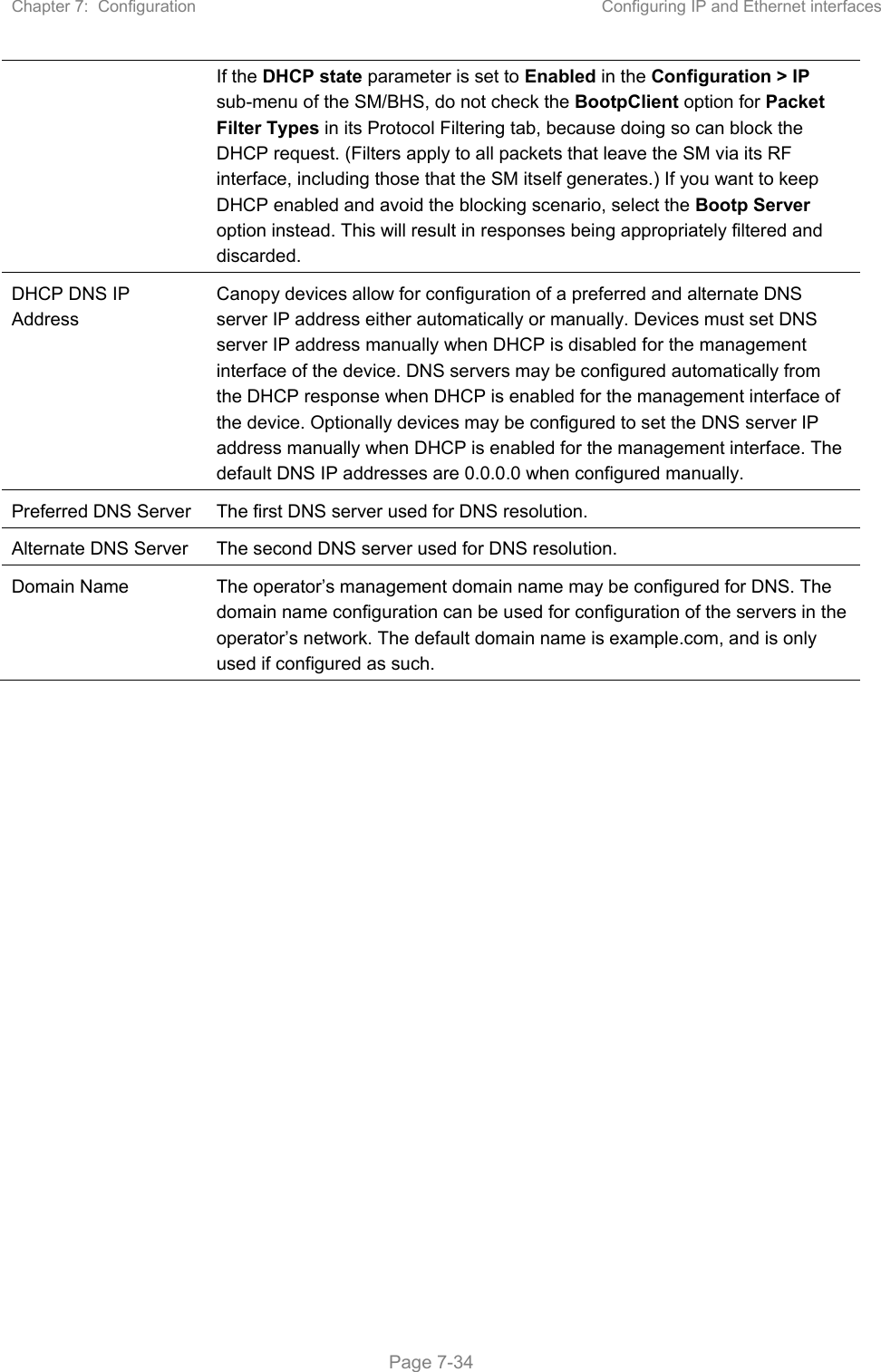

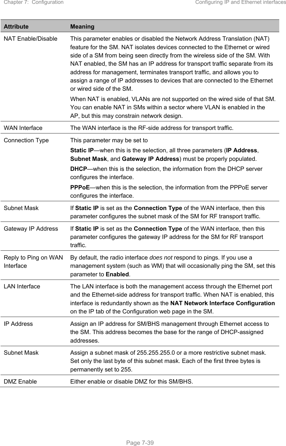
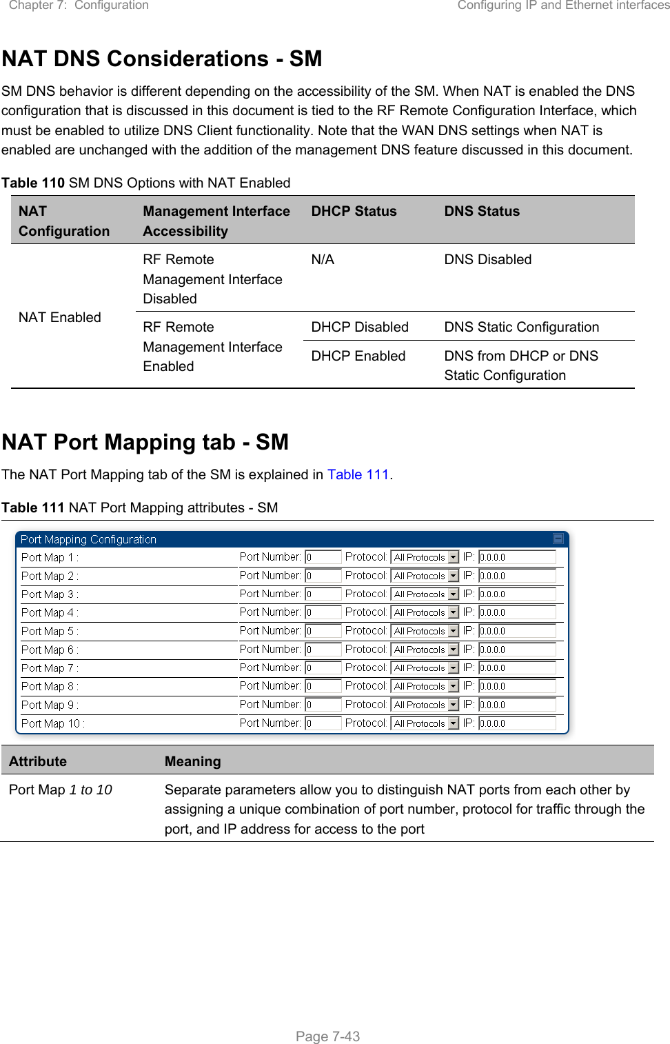
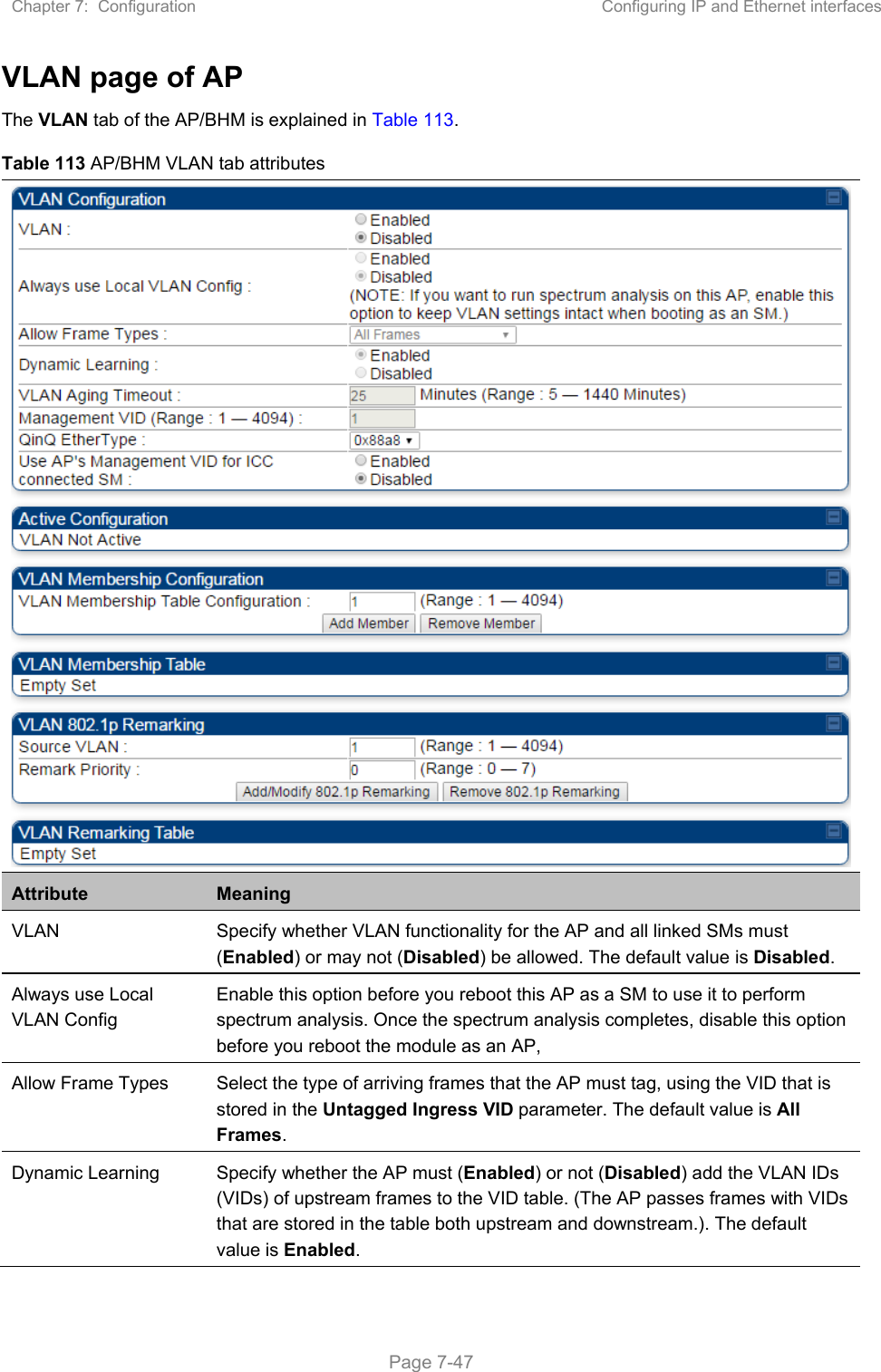
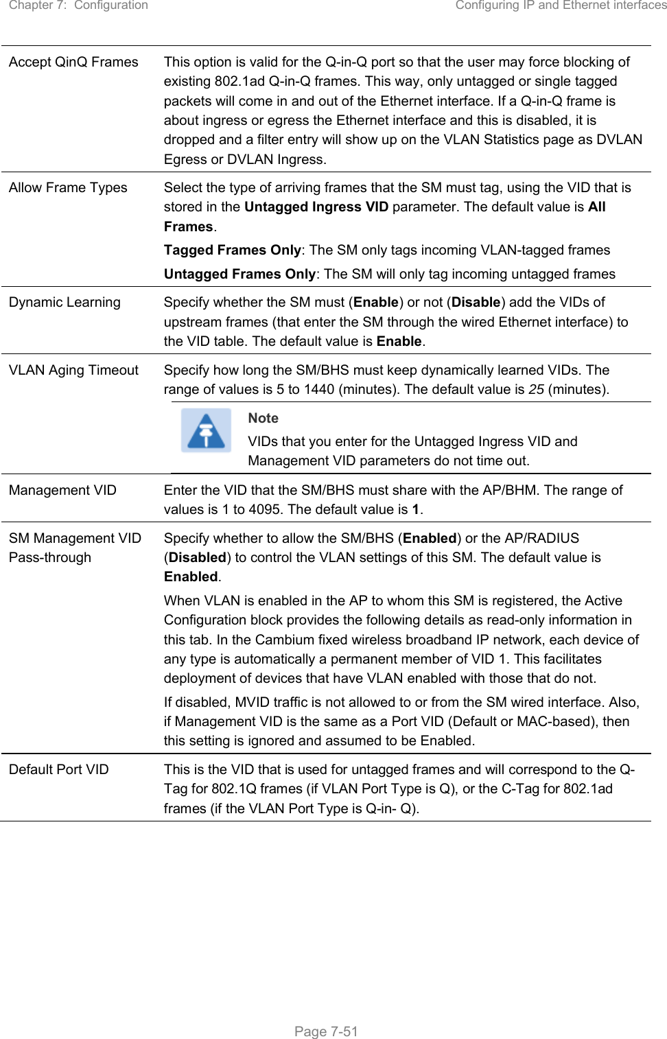
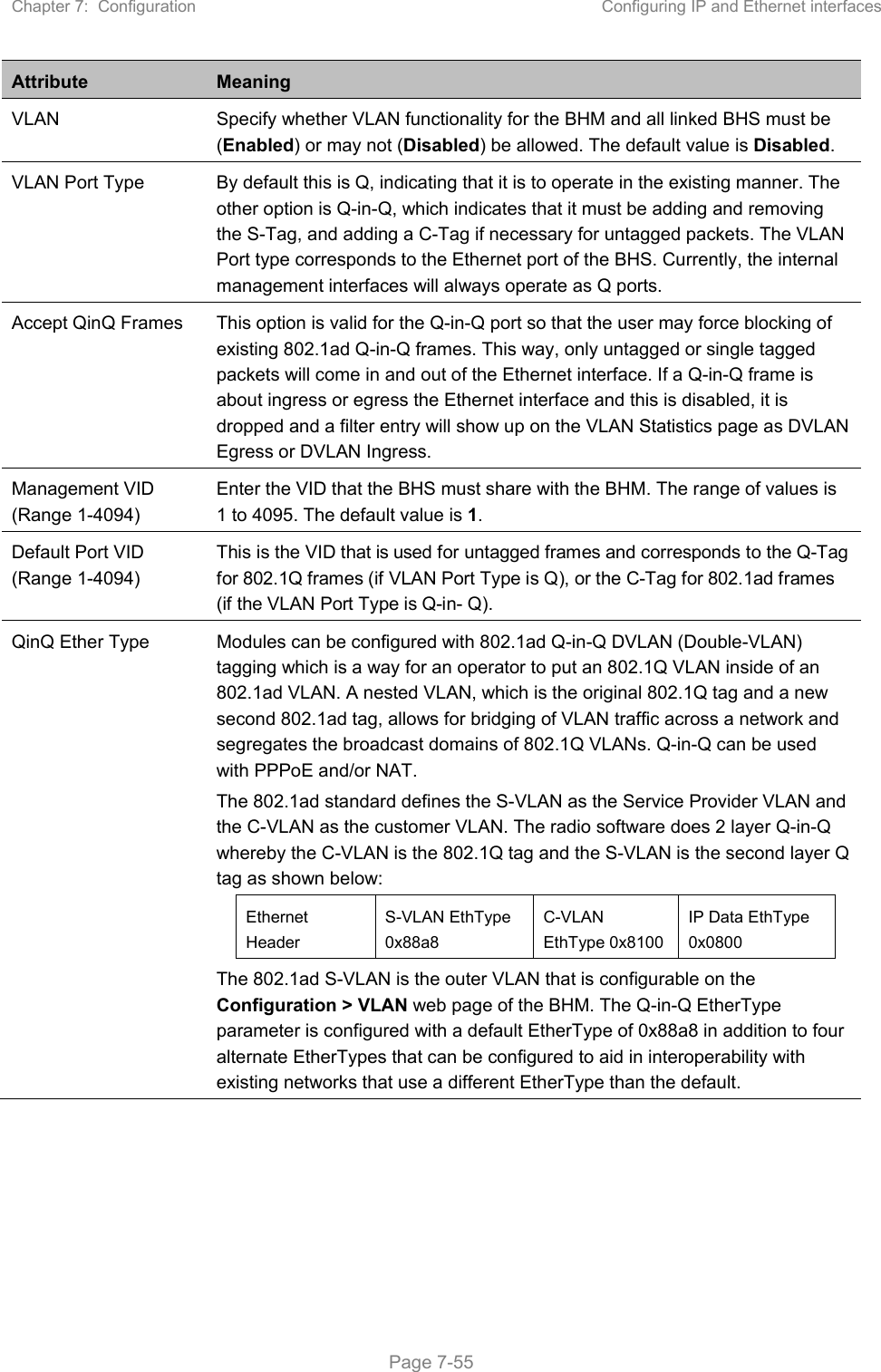
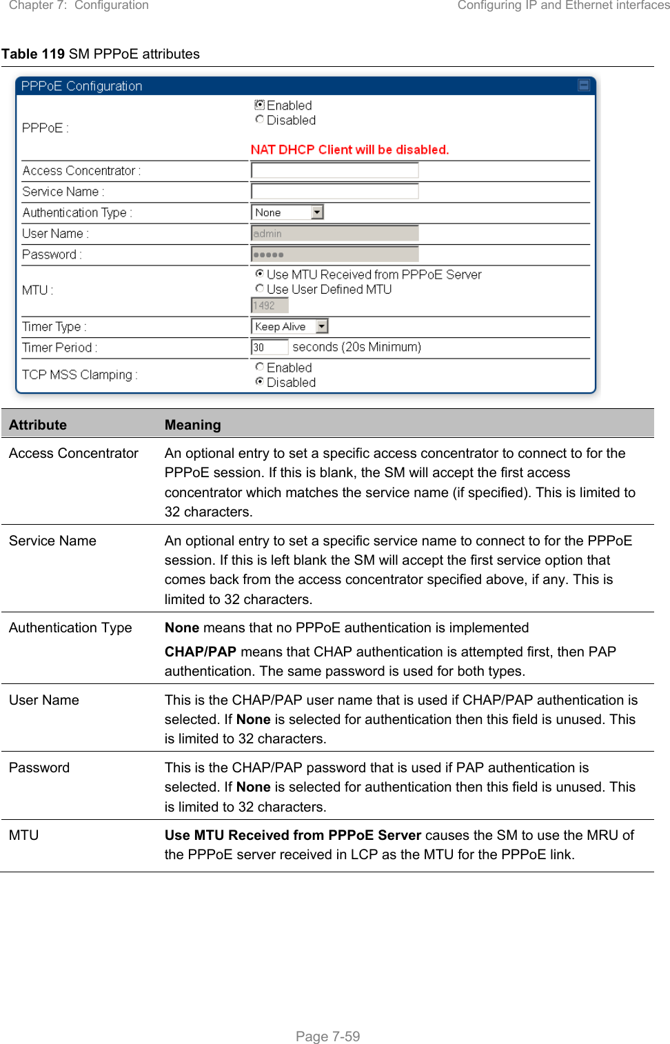
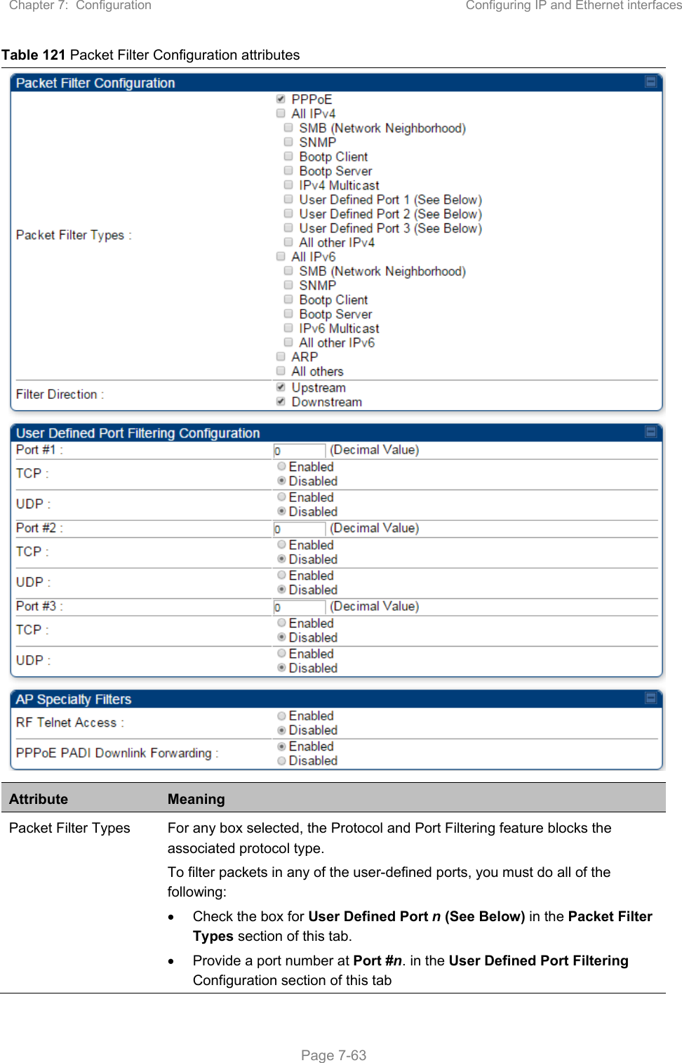
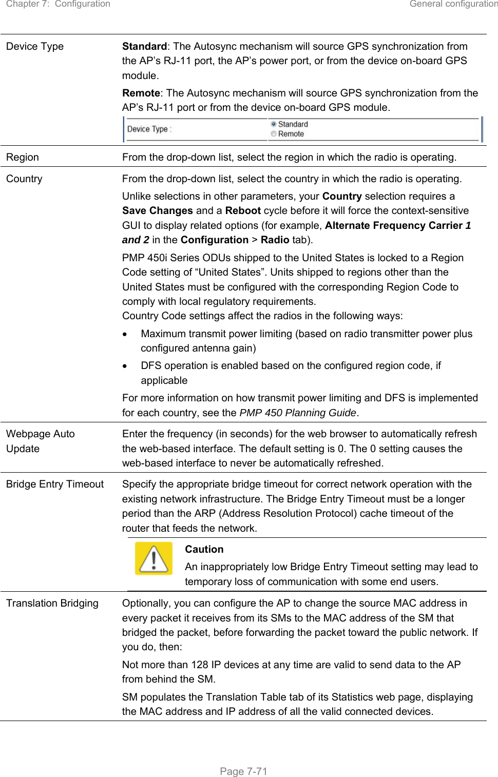
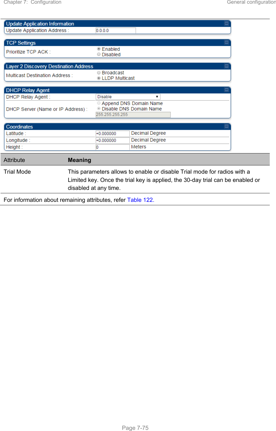
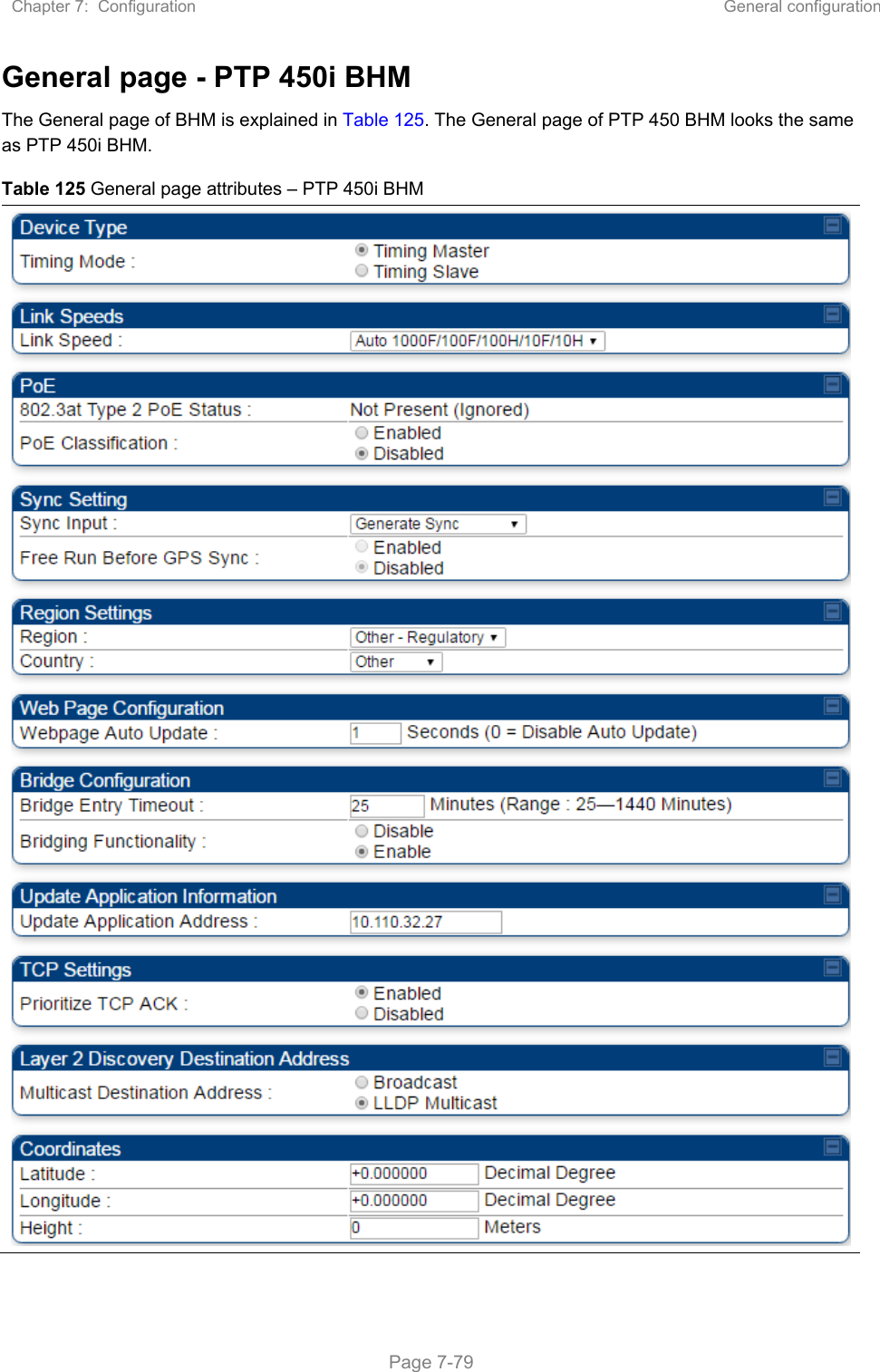
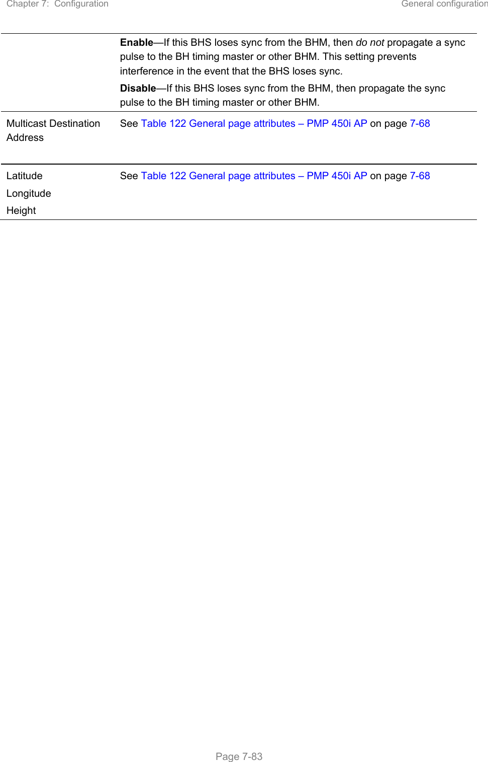
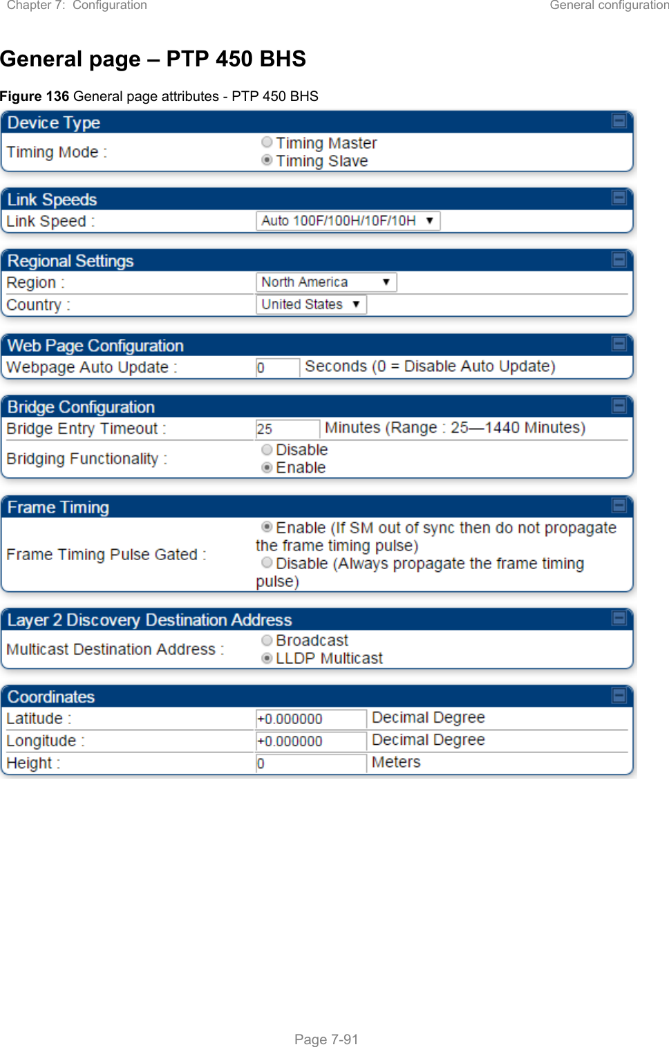
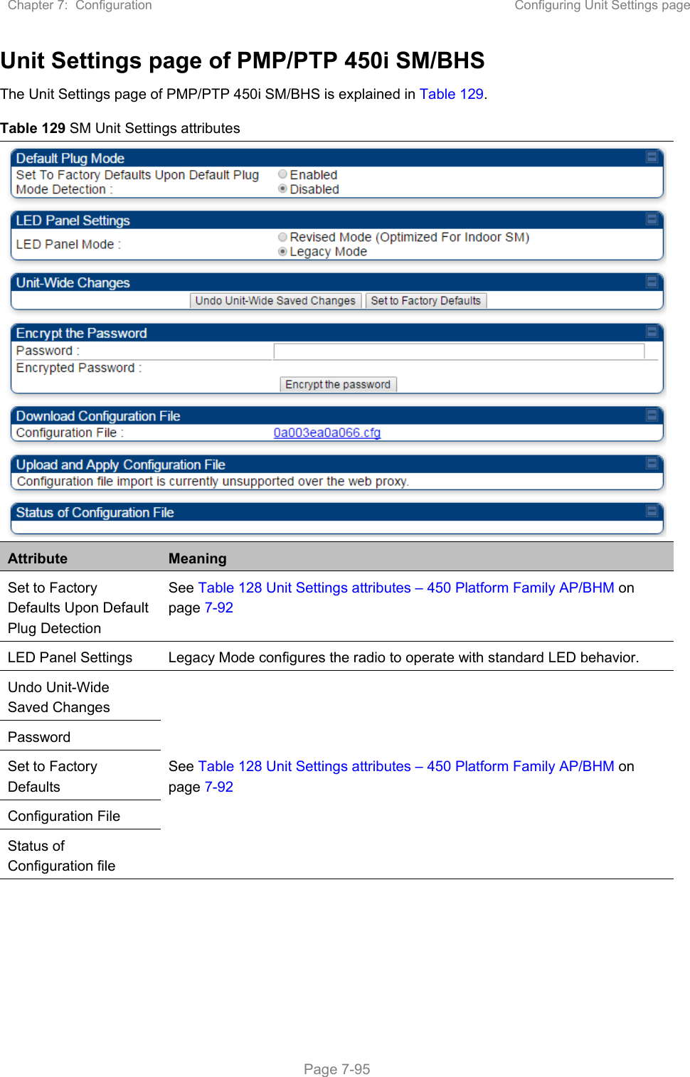

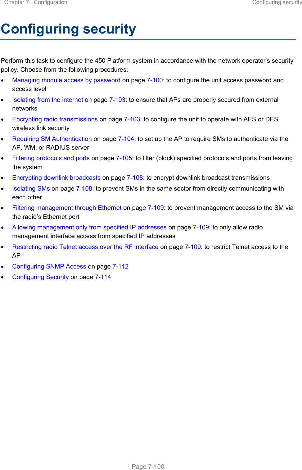
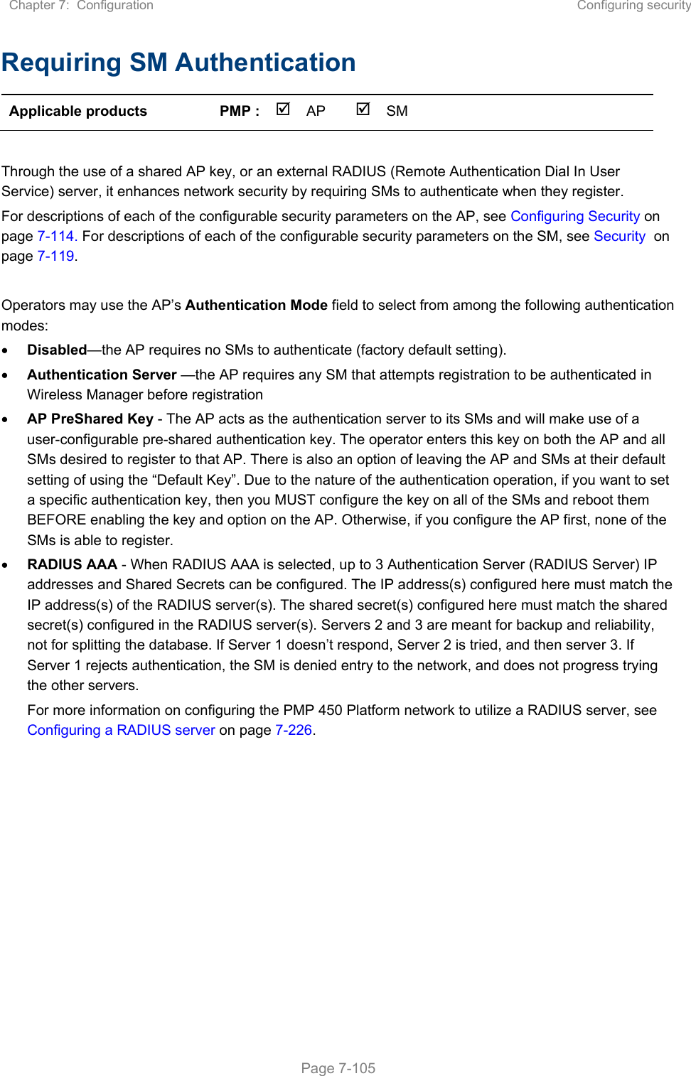
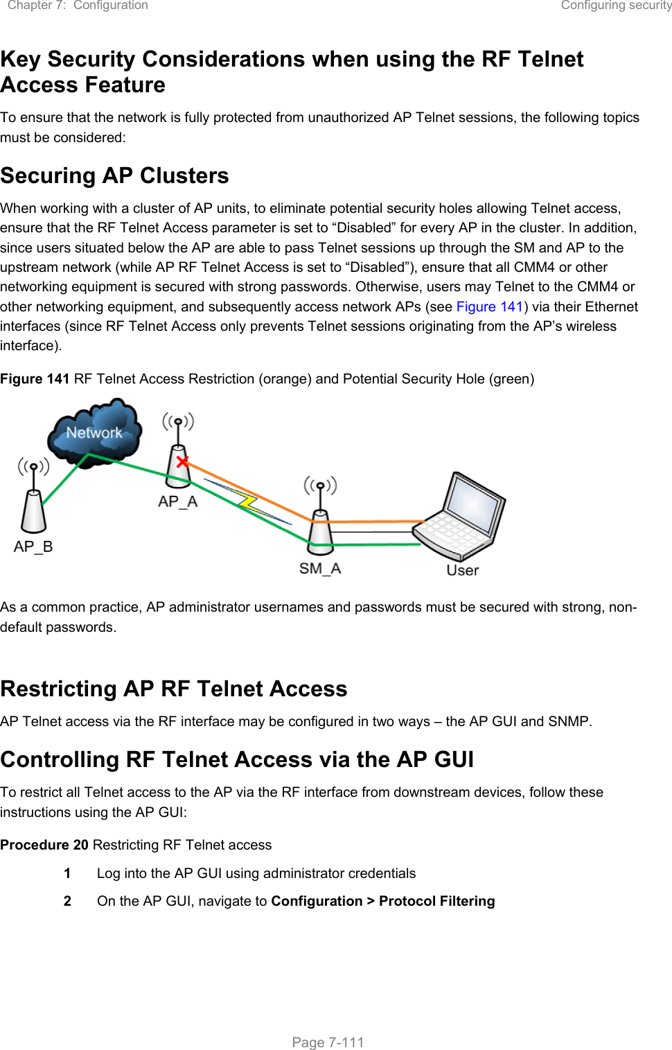
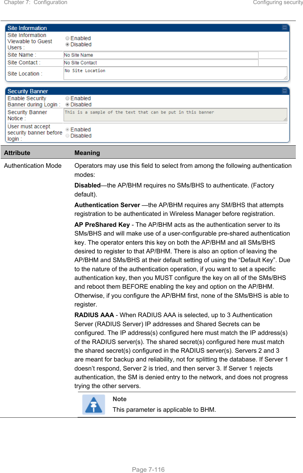
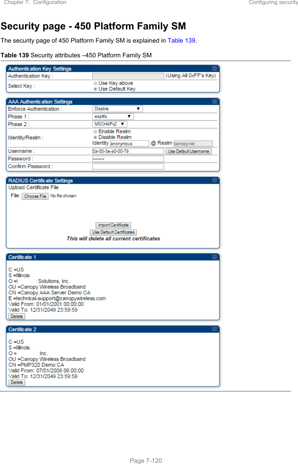
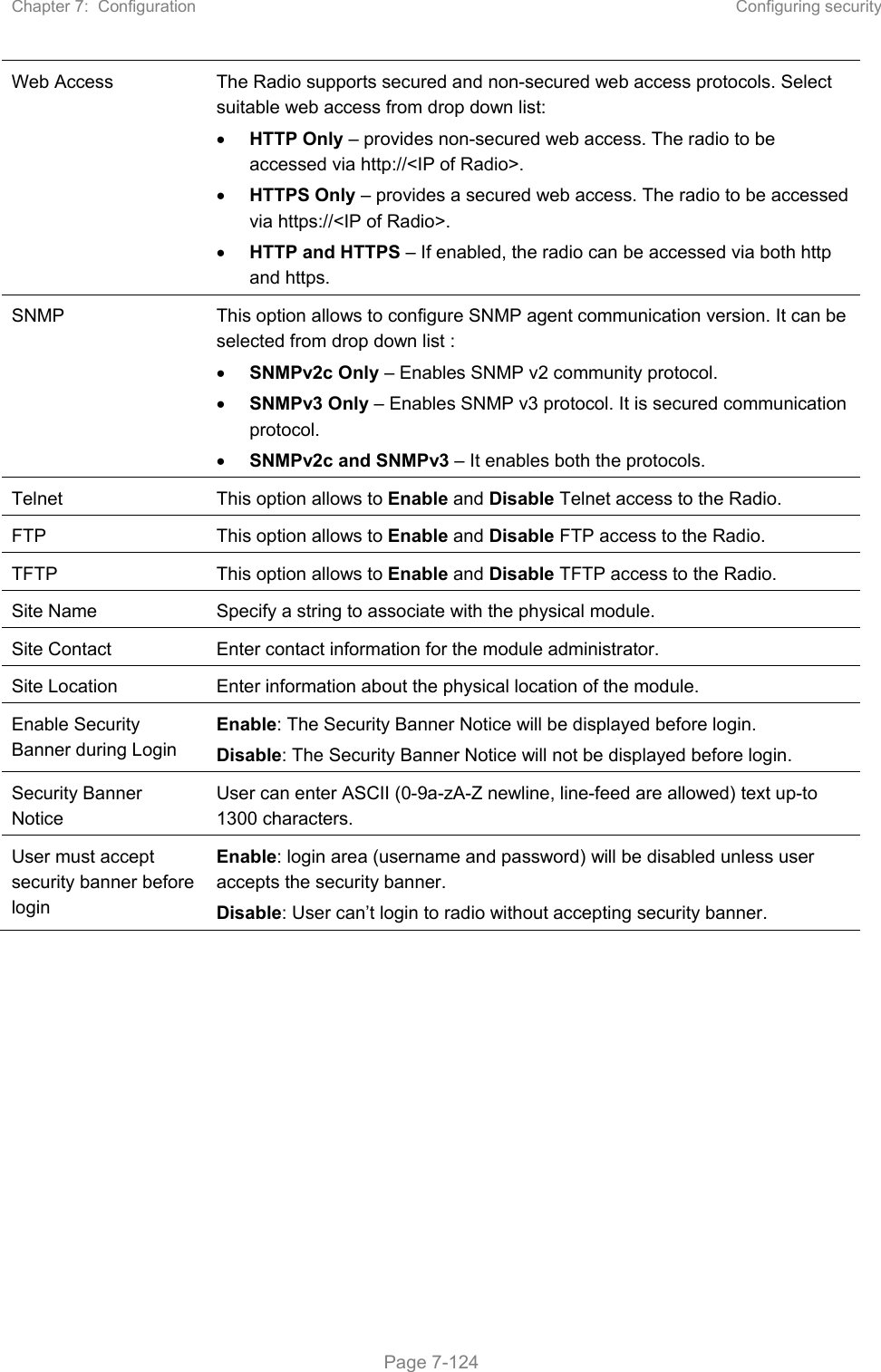
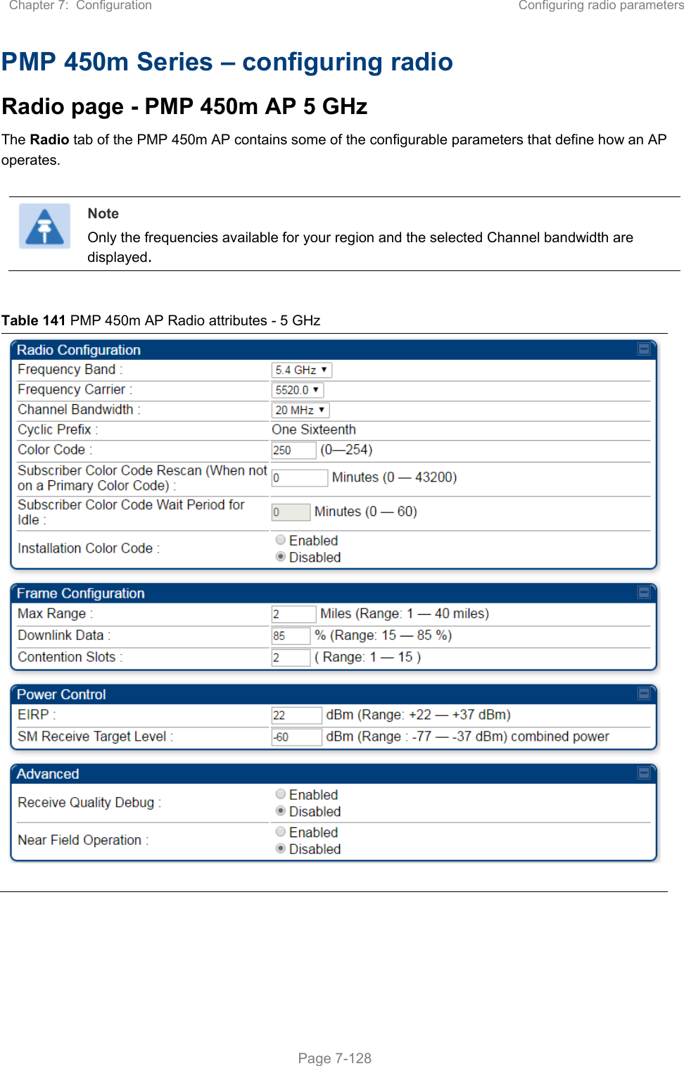
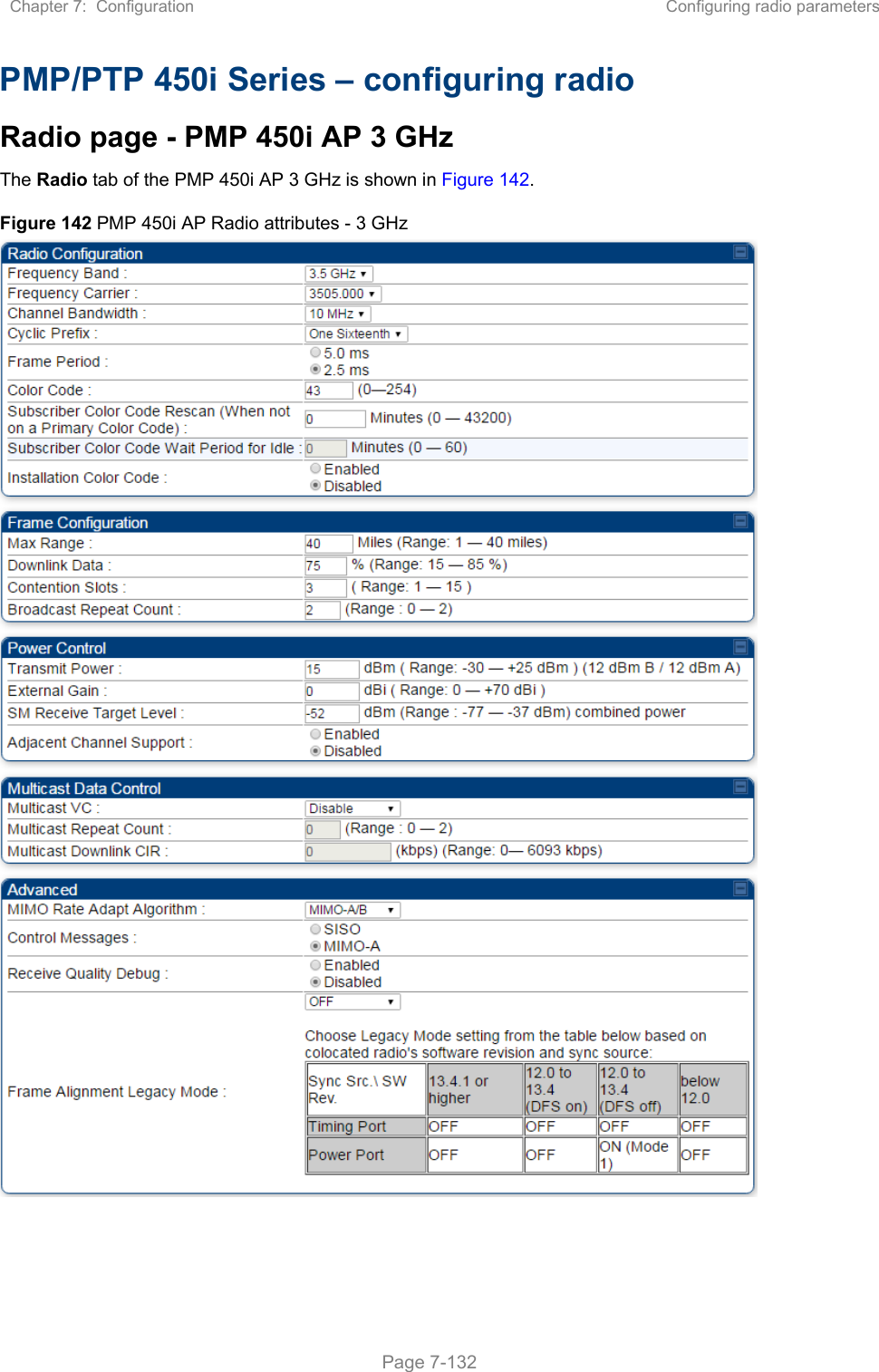
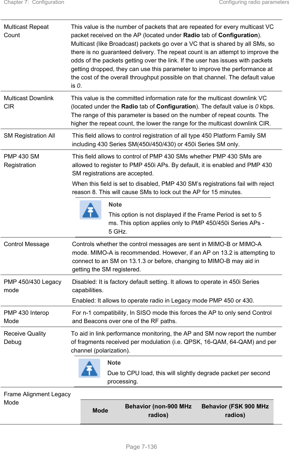
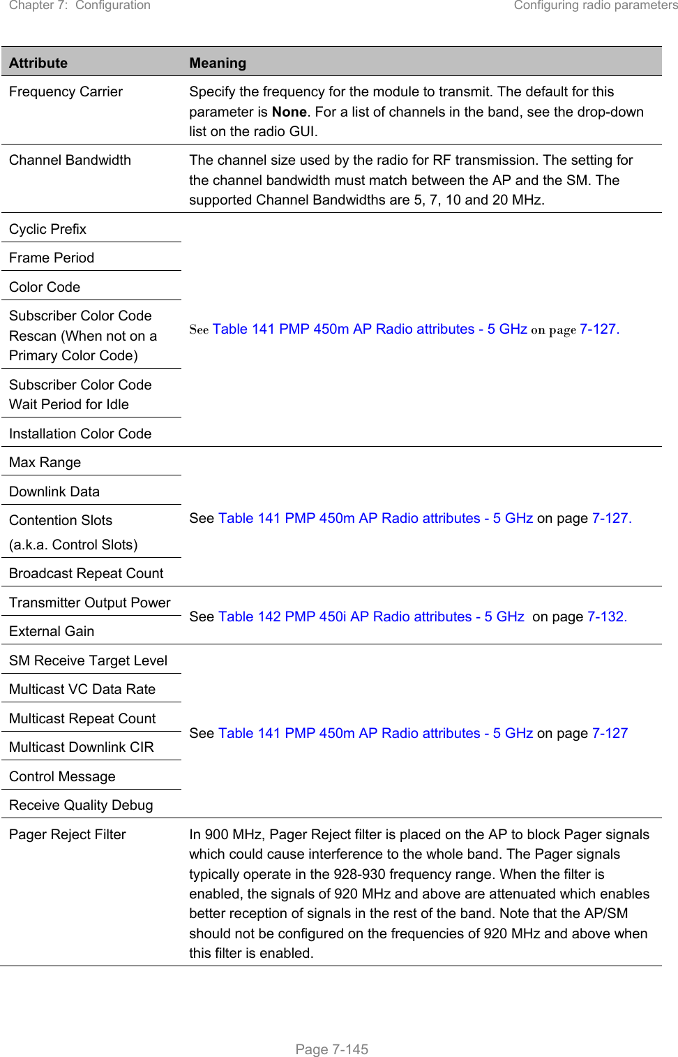
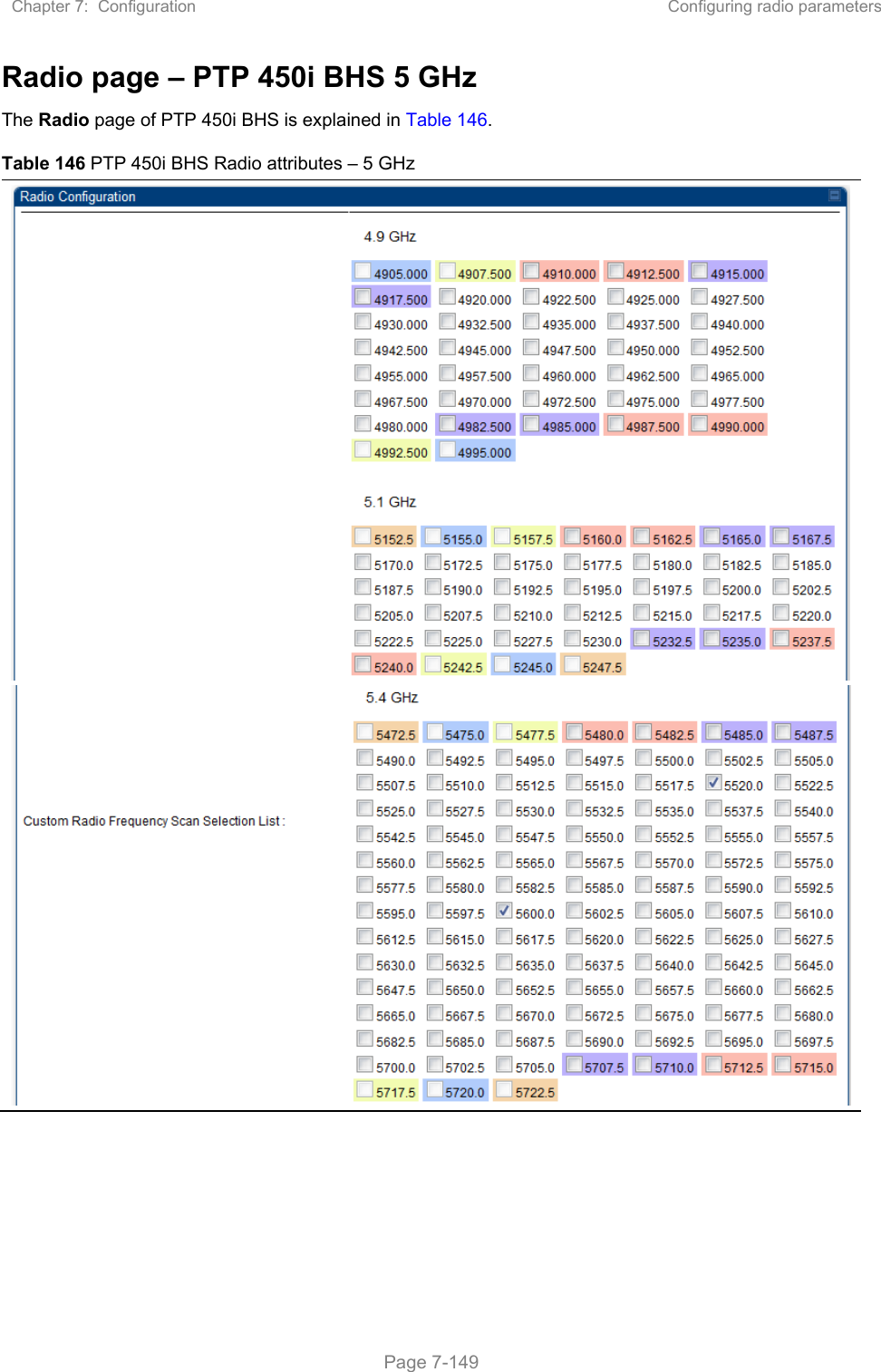
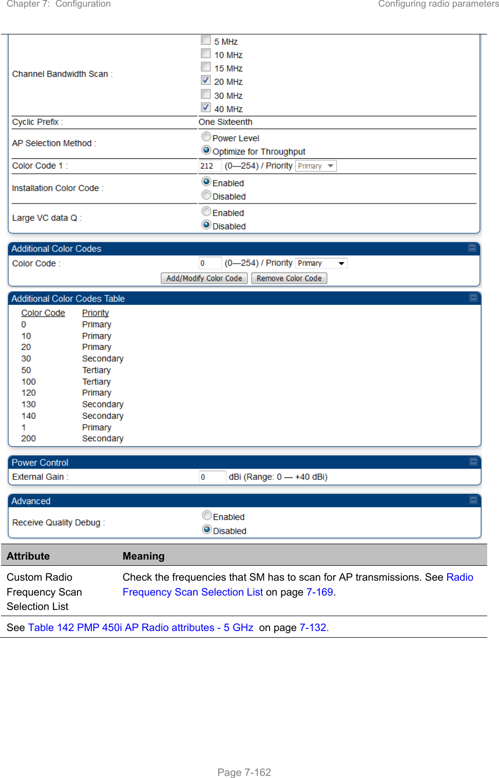
![Chapter 7: Configuration Configuring security Page 7-107 Attribute Meaning Packet Filter Types For any box selected, the Protocol and Port Filtering feature blocks the associated protocol type. To filter packets in any of the user-defined ports, must do all of the following: Check the box for User Defined Port n (See Below) in the Packet Filter Types section of this tab. In the User Defined Port Filtering Configuration section of this tab: provide a port number at Port #n. enable TCP and/or UDP by clicking the associated radio button Filter Direction Operators may choose to filter upstream (uplink) RF packets or downstream (downlink) RF packets. User Defined Port Filtering Configuration You can specify ports for which to block subscriber access, regardless of whether NAT is enabled. RF Telnet Access RF Telnet Access restricts Telnet access to the AP/BHM from a device situated below a network SM/BHS (downstream from the AP/BHM). This is a security enhancement to restrict RF-interface sourced AP access specifically to the LAN1 IP address and LAN2 IP address (Radio Private Address, typically 192.168.101.[LUID]). This restriction disallows unauthorized users from running Telnet commands on the AP/BHM that can change AP/BHM configuration or modifying network-critical components such as routing and ARP tables. PPPoE PADI Downlink Forwarding Enabled: the AP/BHM allows downstream and upstream transmission of PPPoE PADI packets. By default, PPPoE PADI Downlink Forwarding is set to “Enabled”. Disabled: the AP/BHM disallows PPPoE PADI packets from entering the Ethernet interface and exiting the RF interface (downstream to the SM/BHS). PPPoE PADI packets are still allowed to enter the AP’s RF interface and exit the AP’s /BHM’s Ethernet interface (upstream).](https://usermanual.wiki/Cambium-Networks/50450M.USERS-MANUAL-PART2/User-Guide-3650883-Page-124.png)
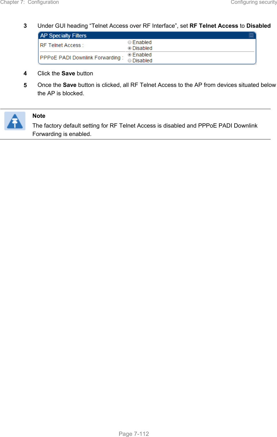
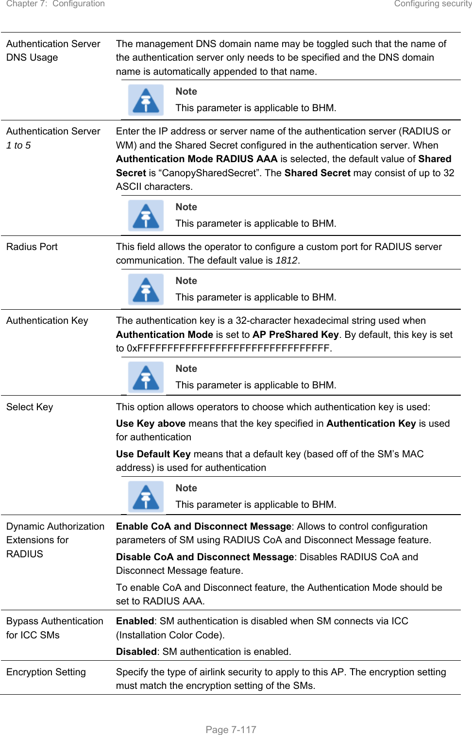
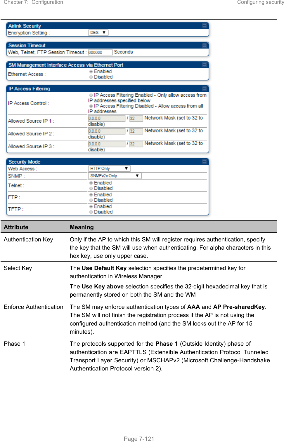
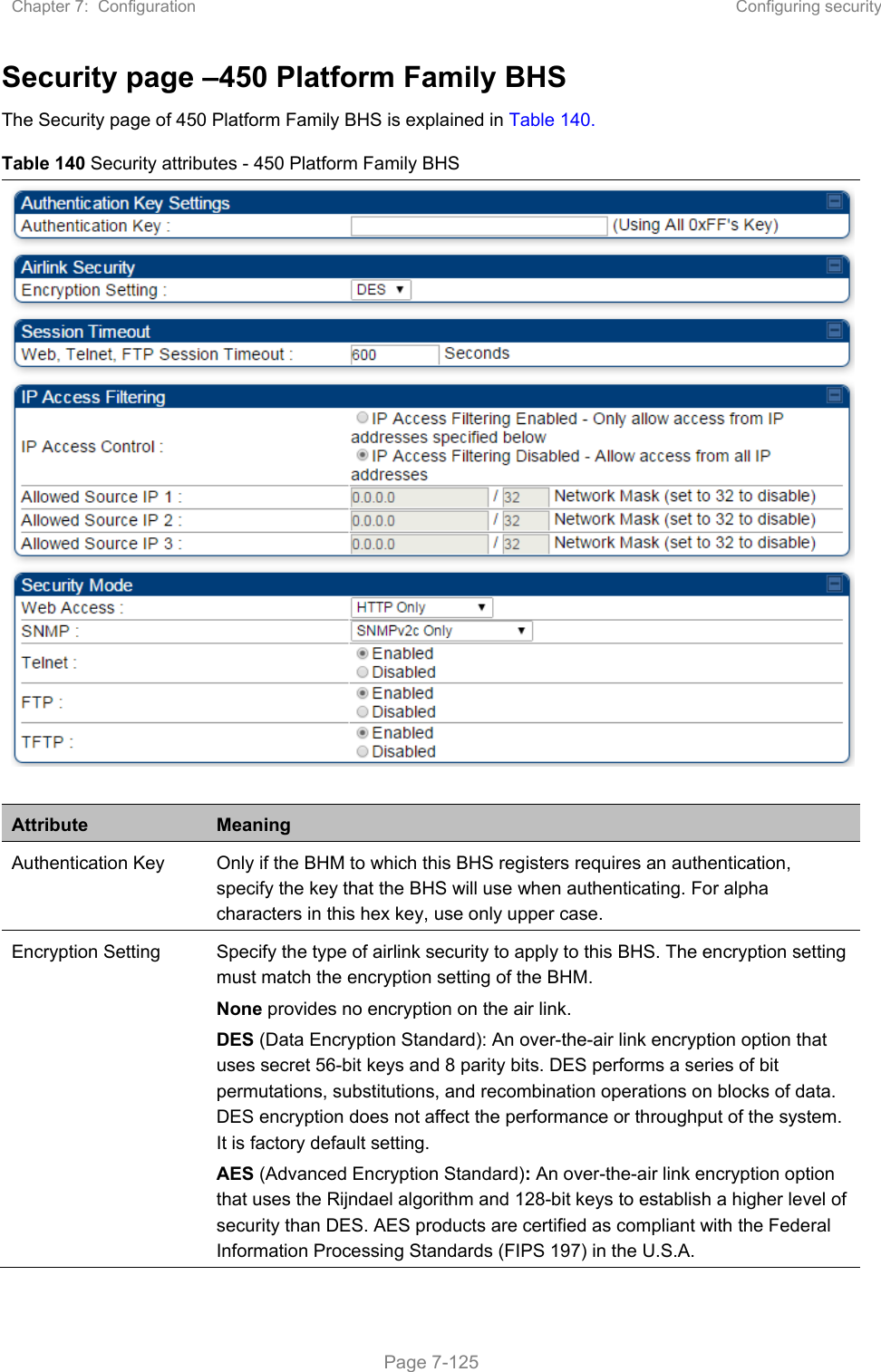
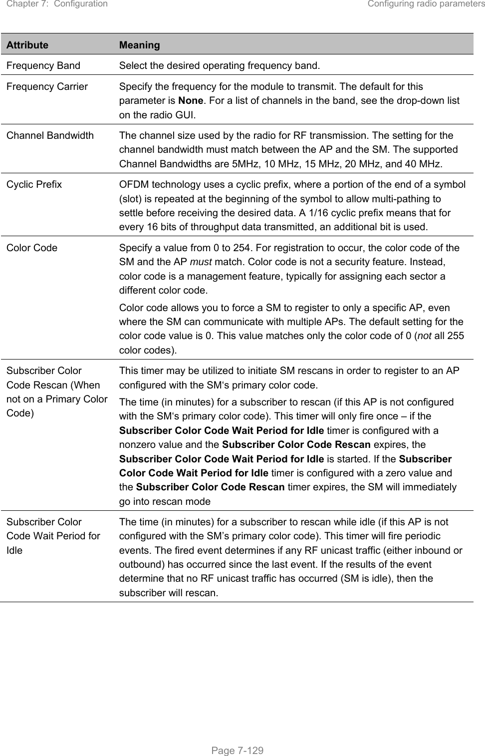
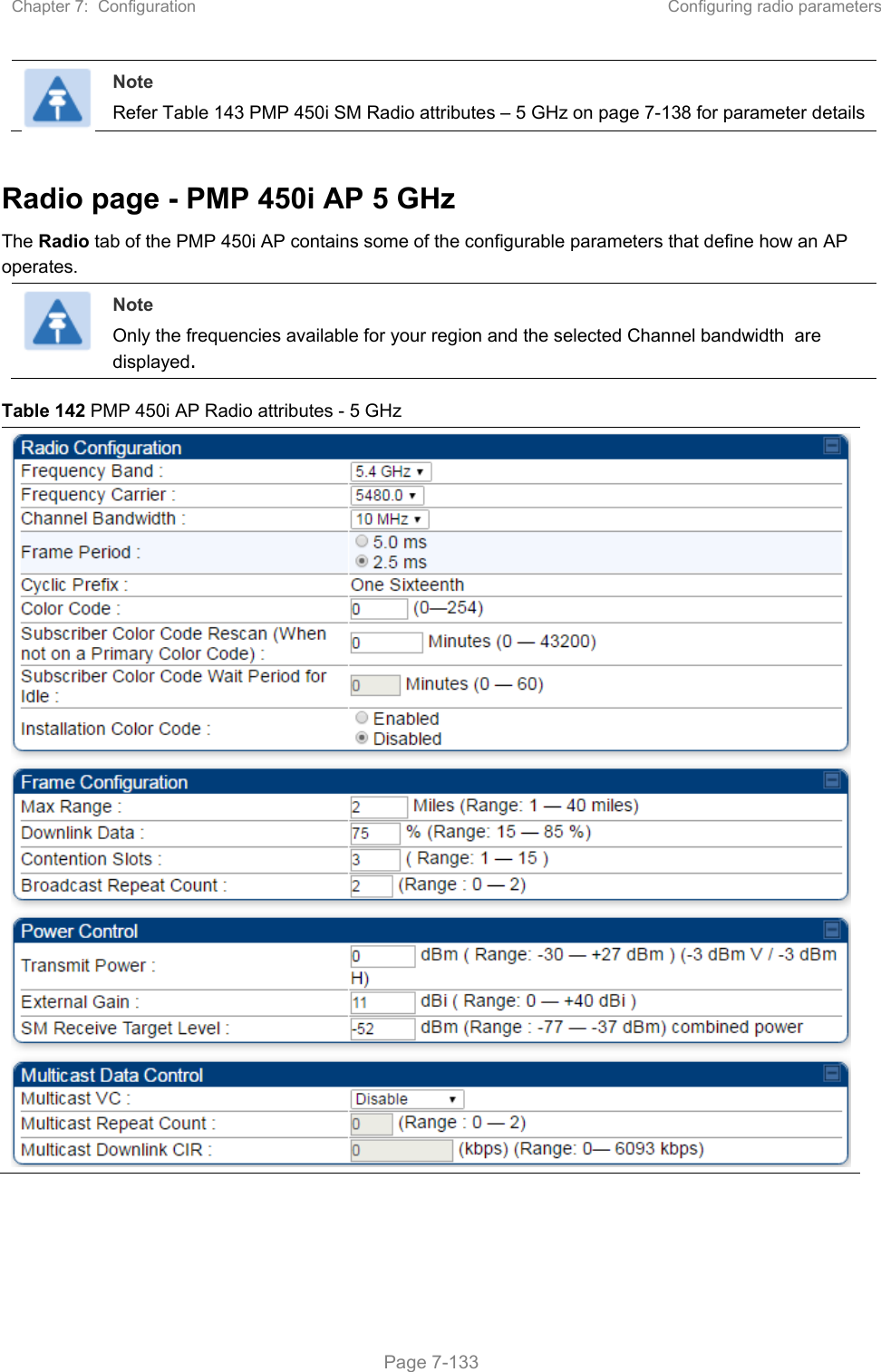
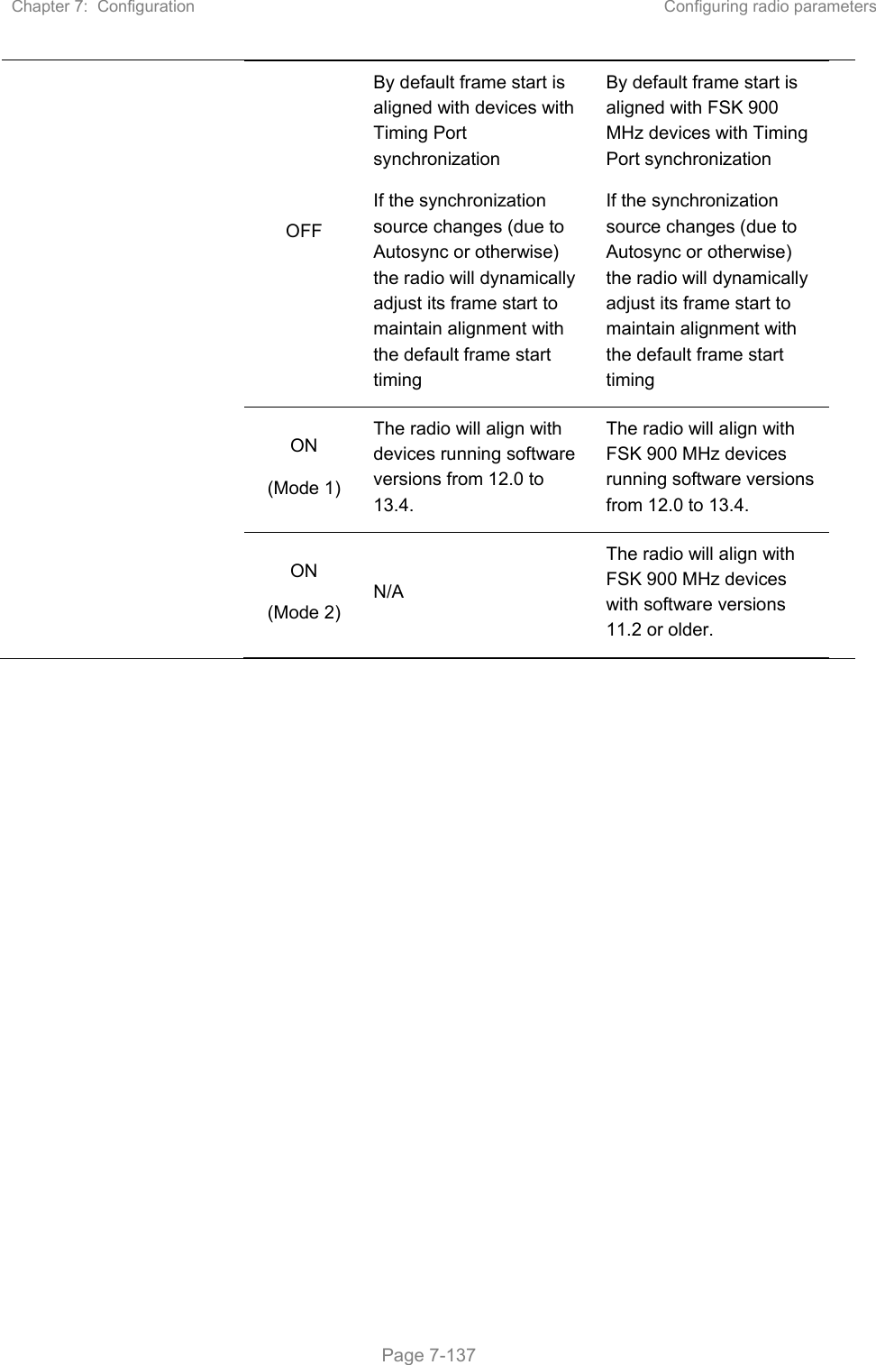
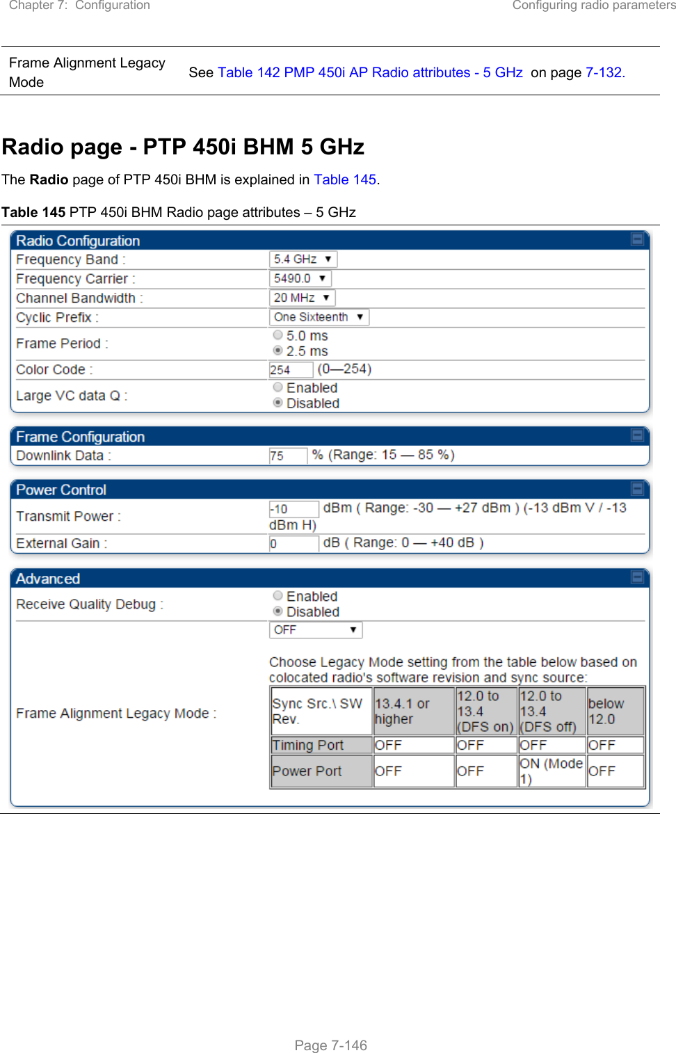
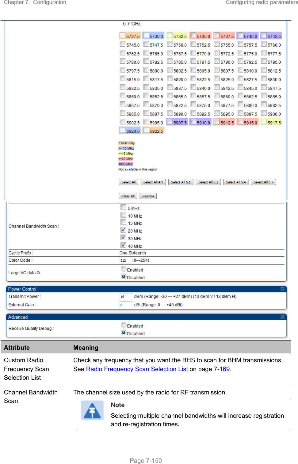
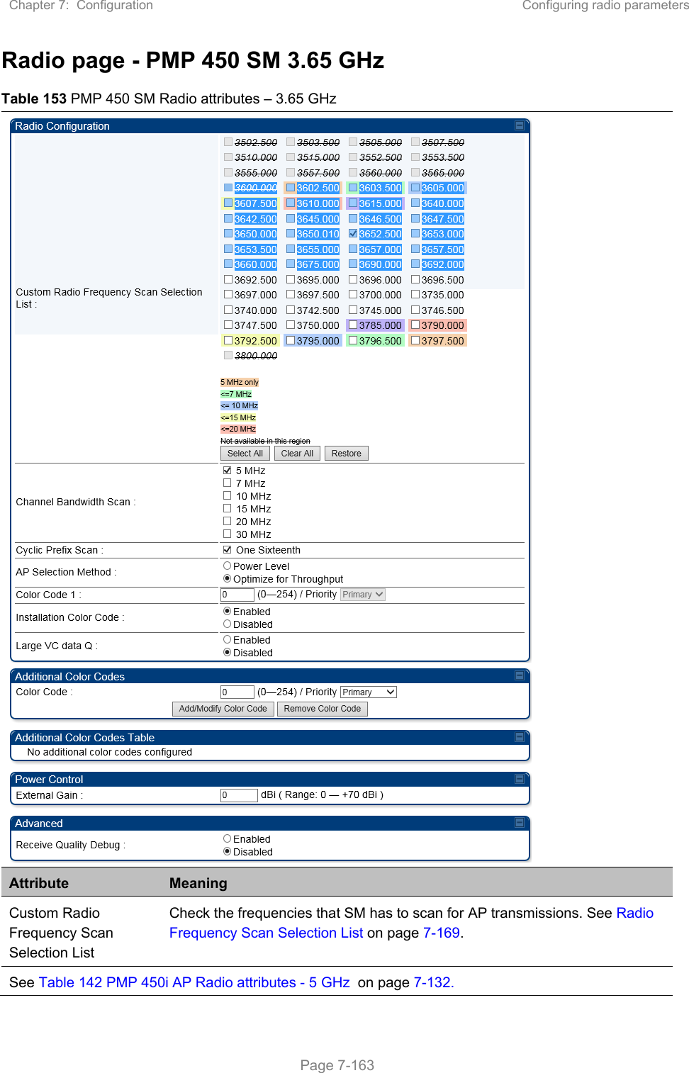
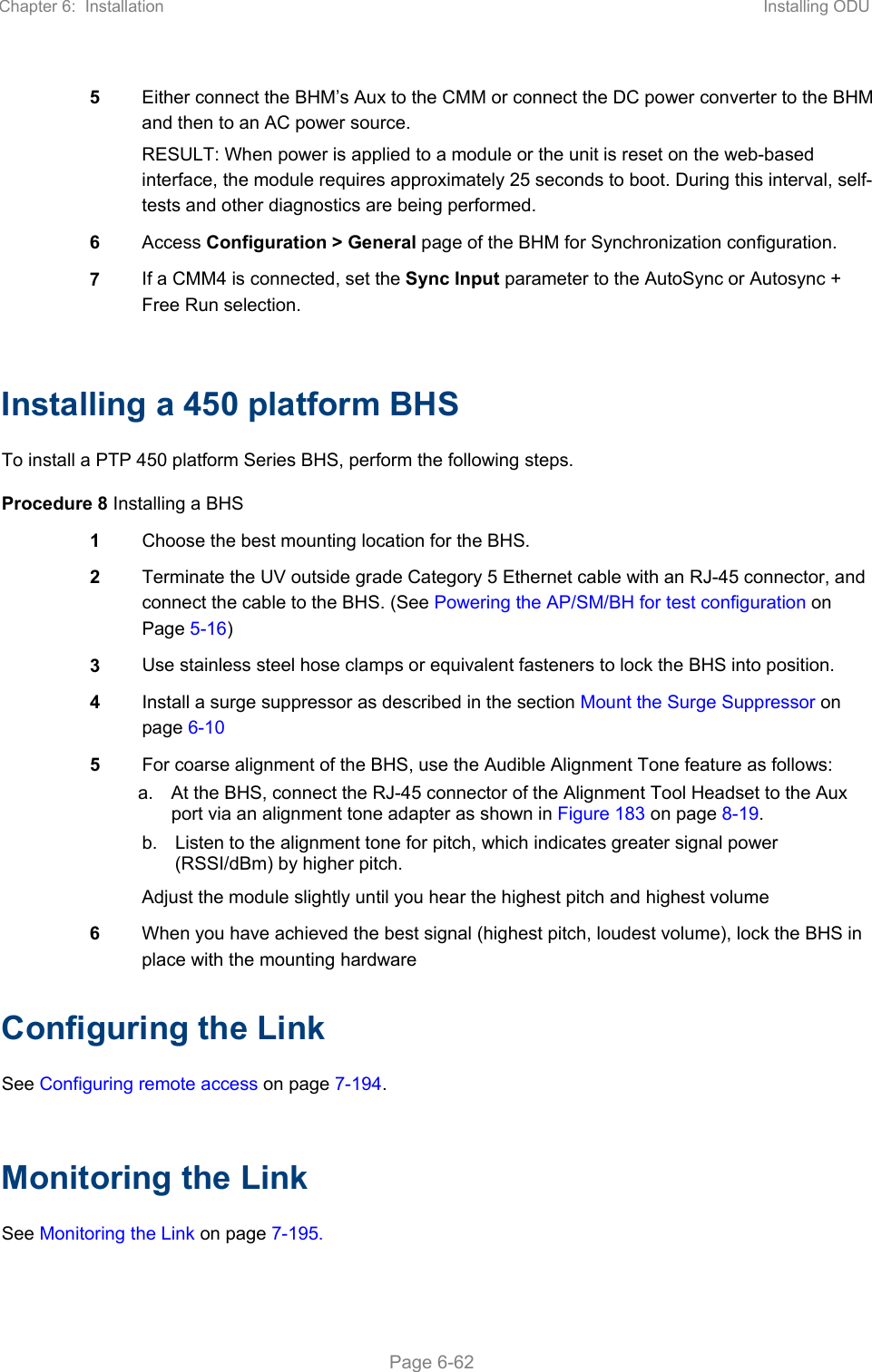
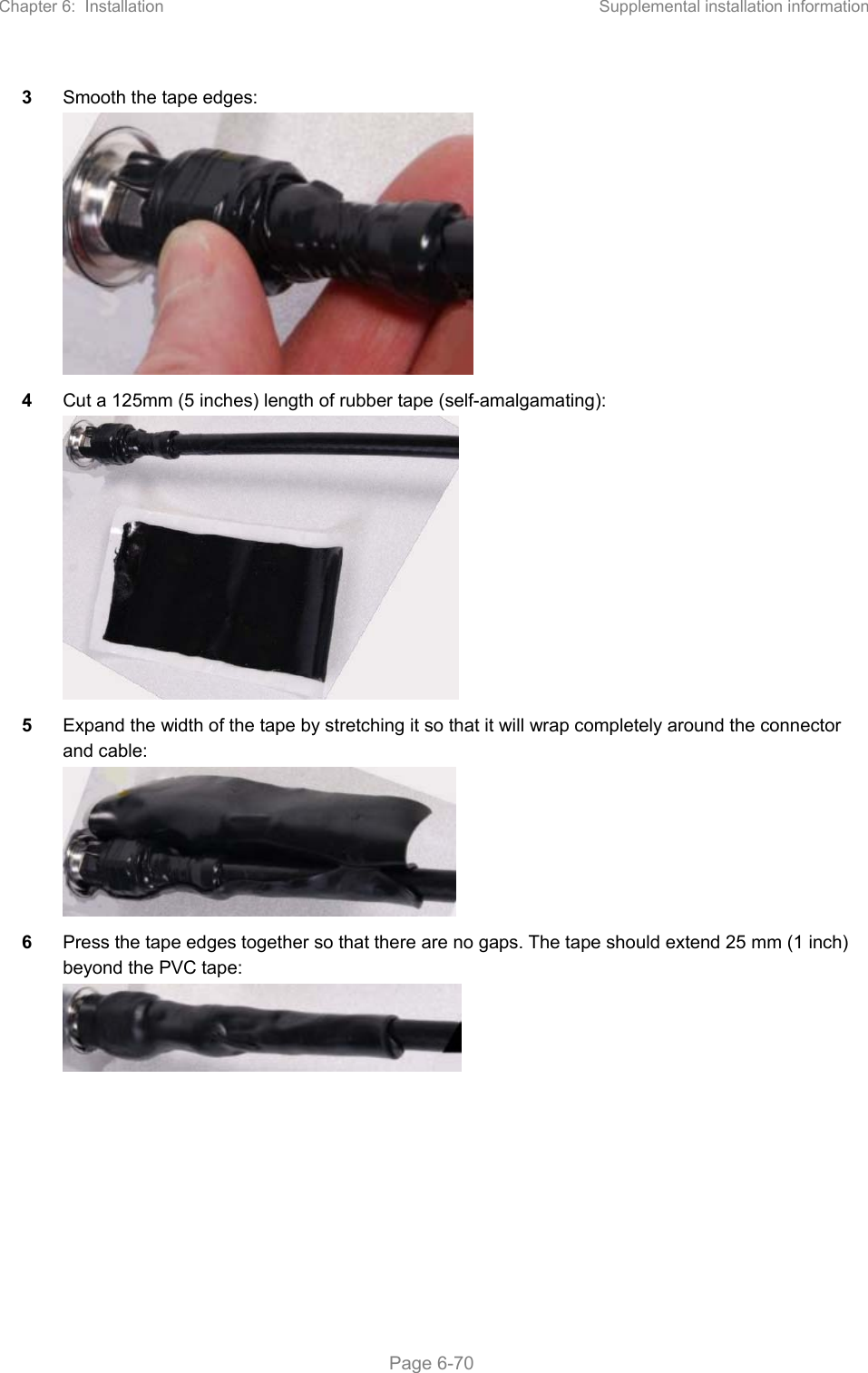
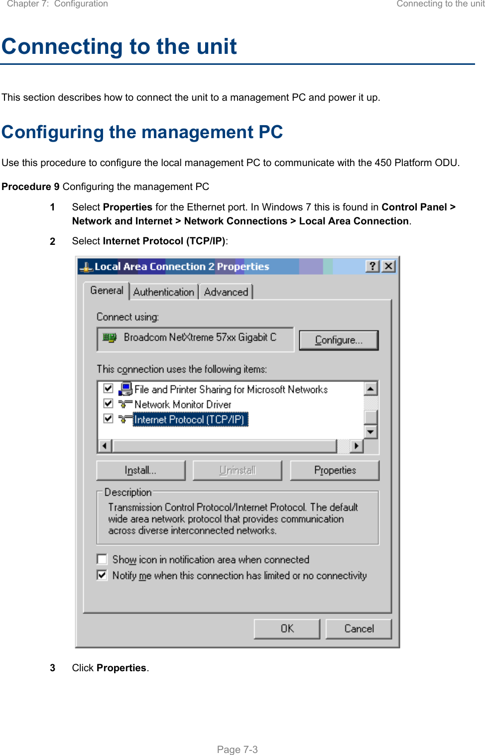
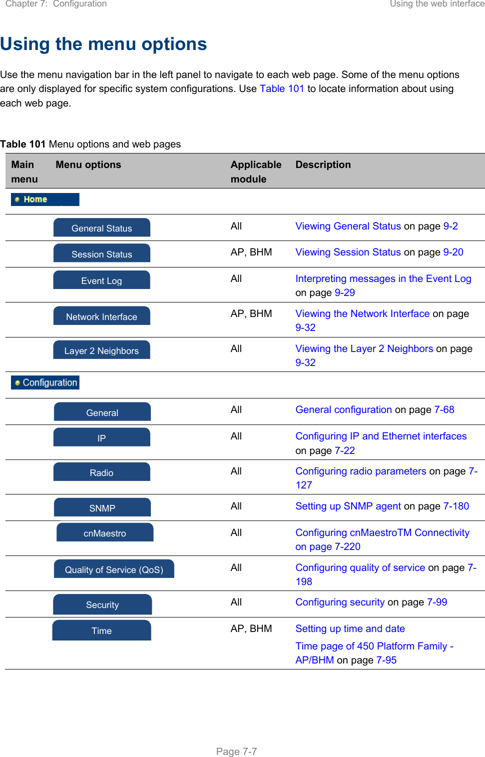
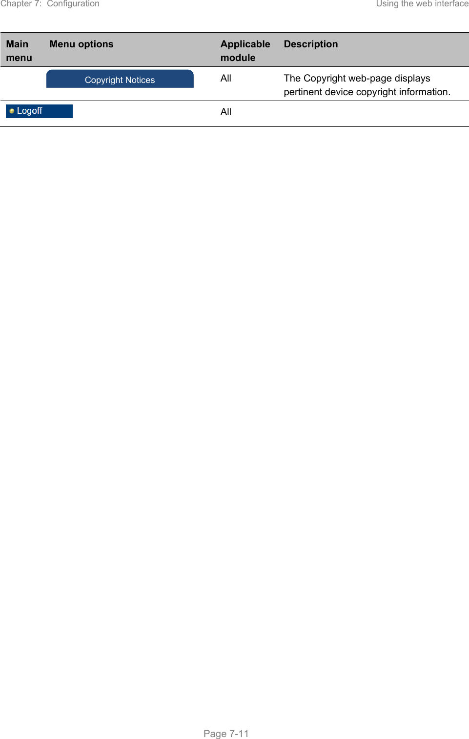
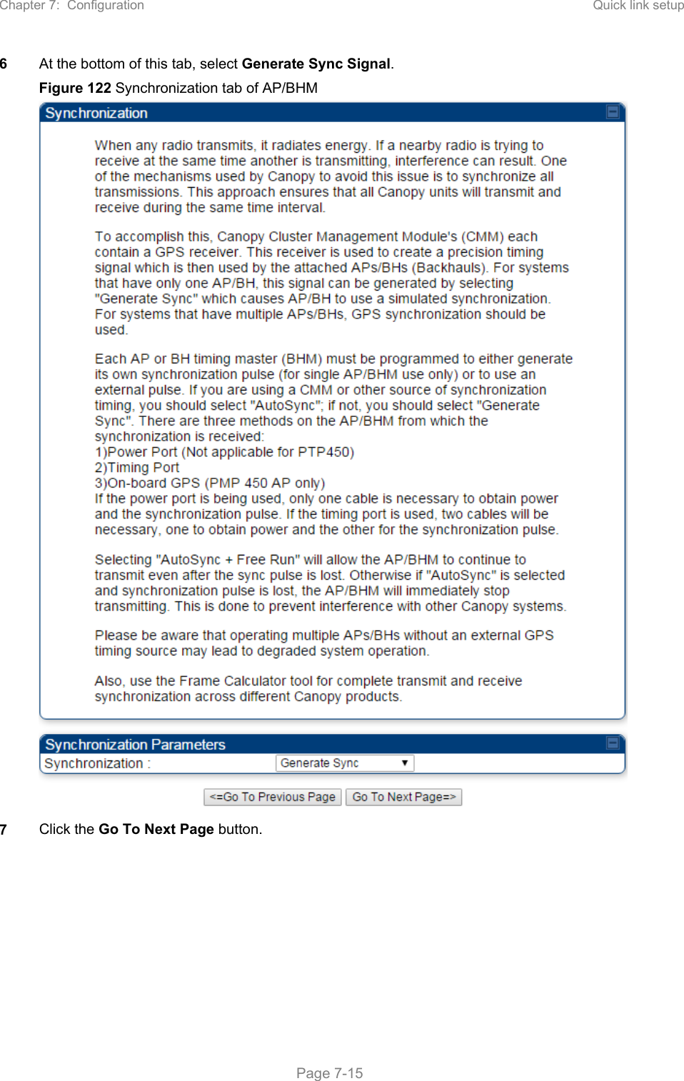
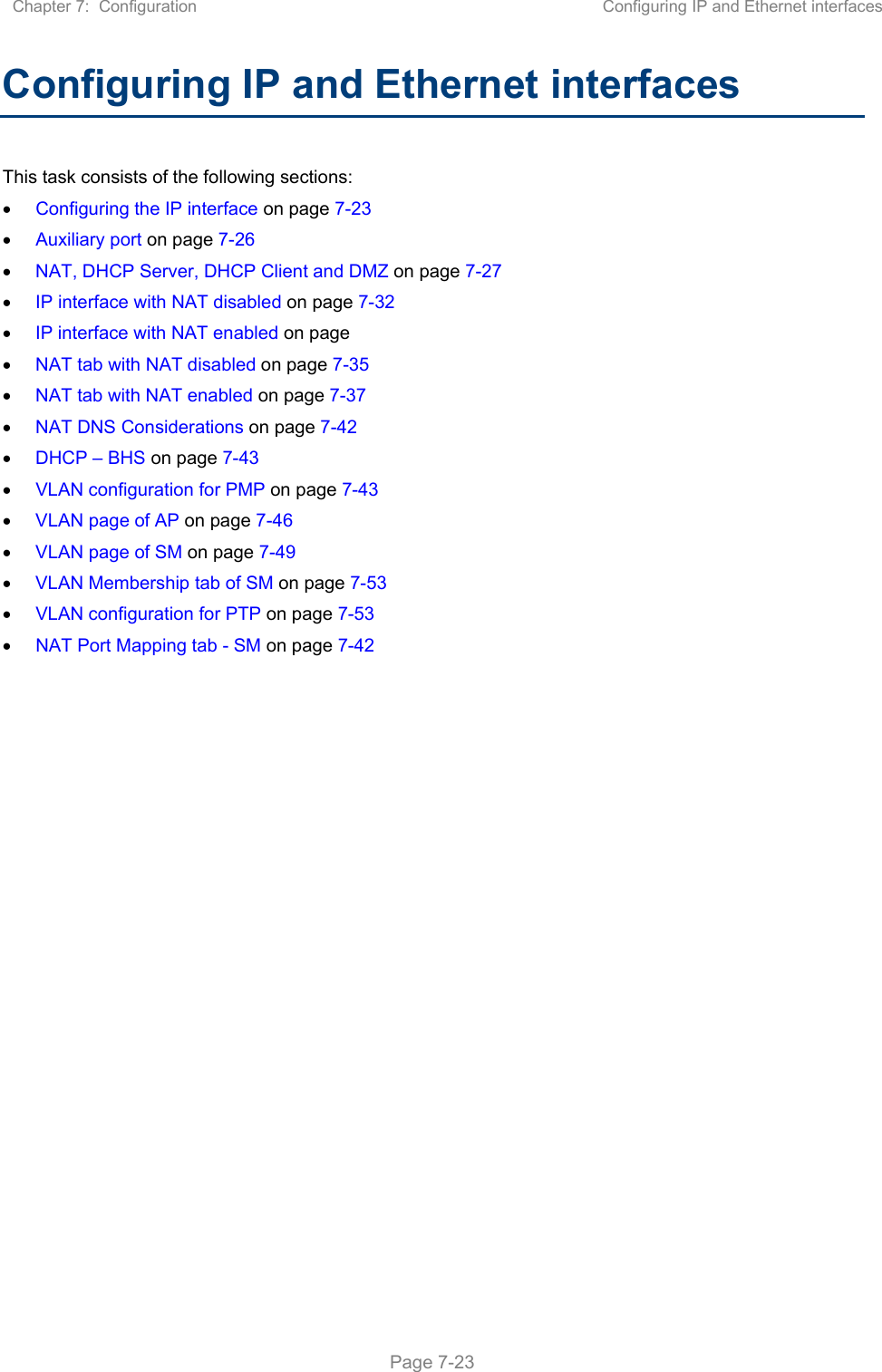
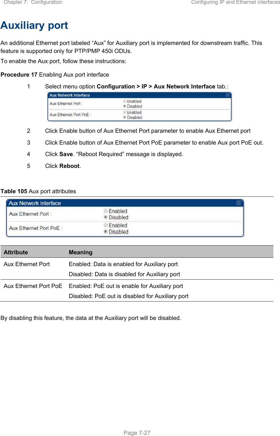
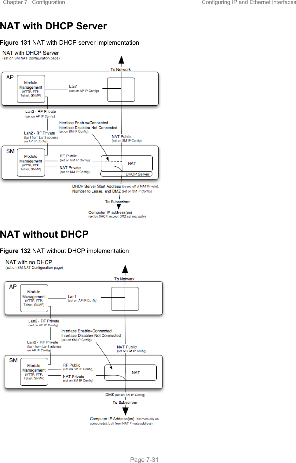
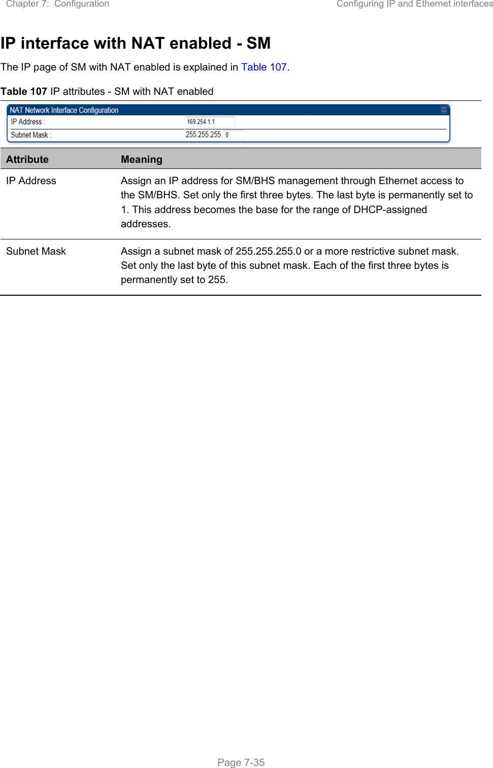
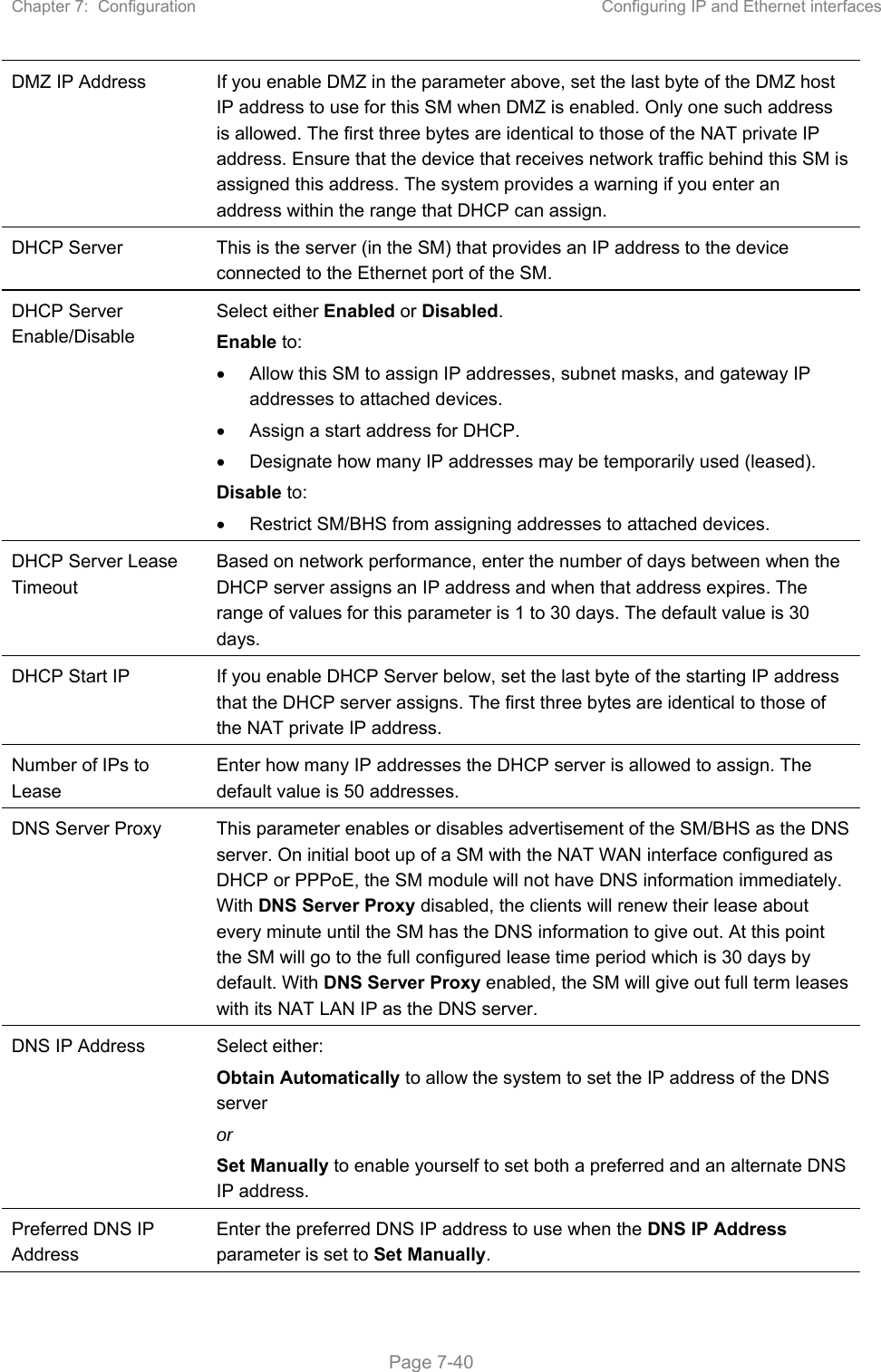
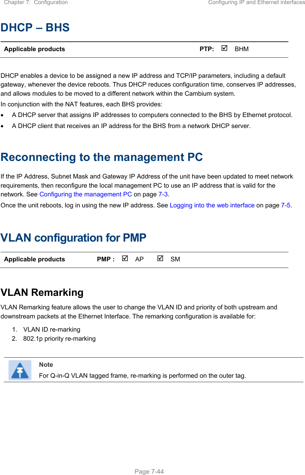
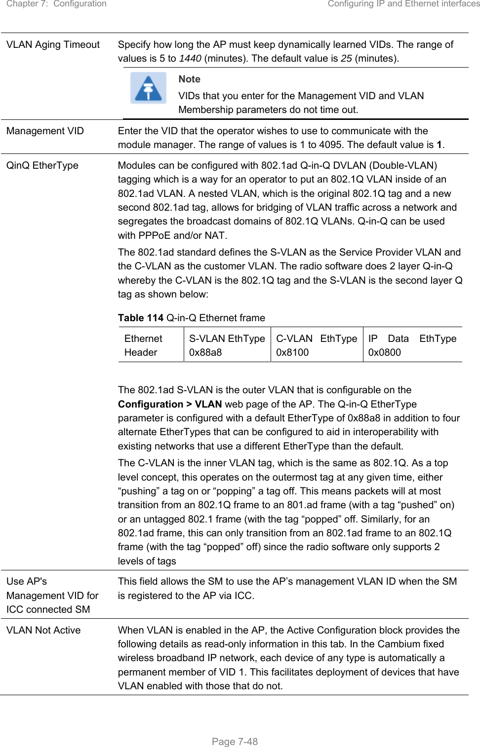
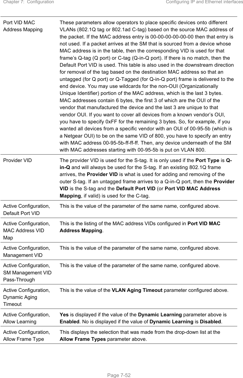
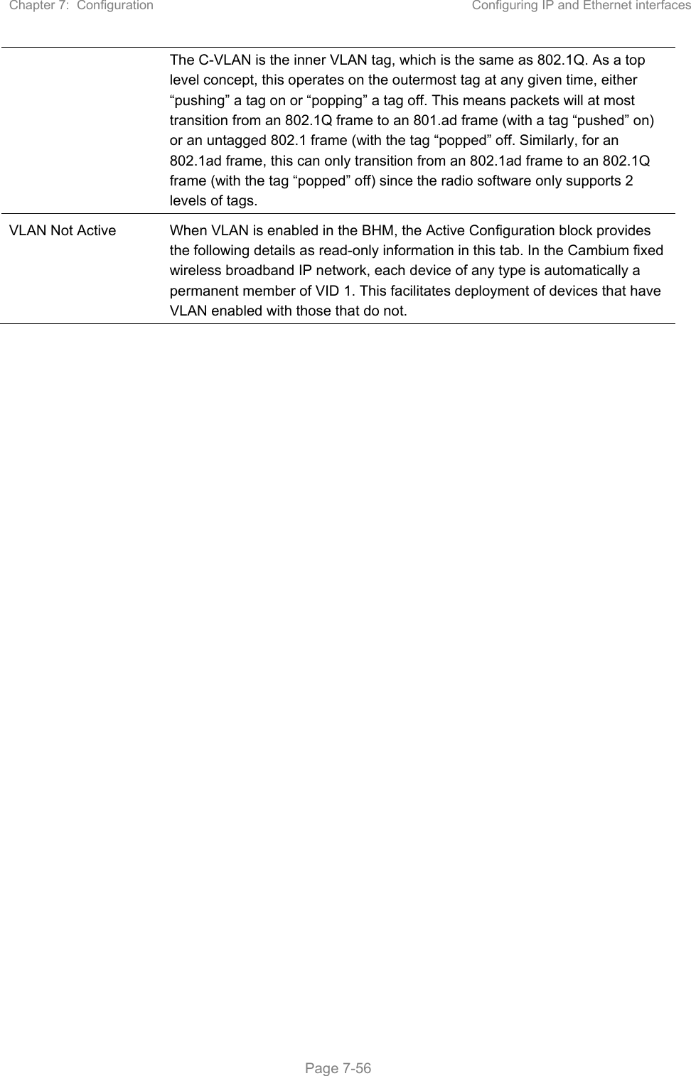
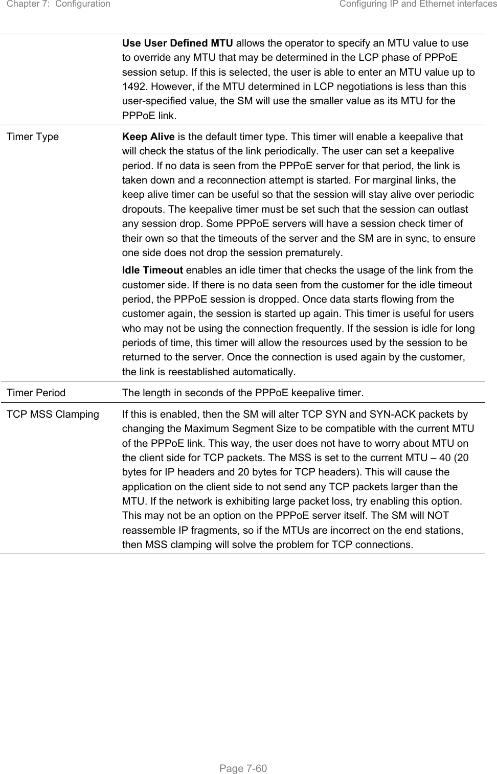
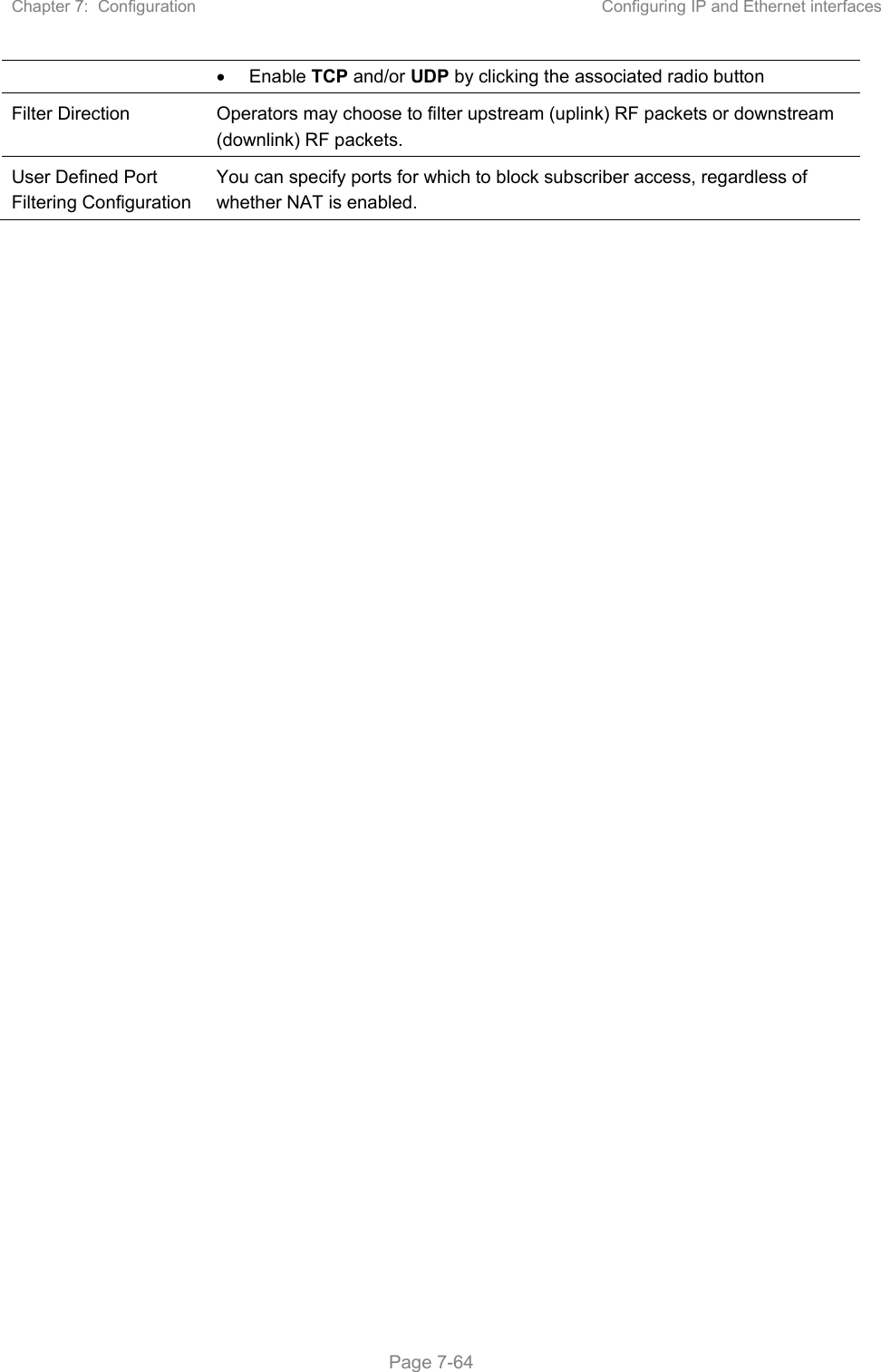
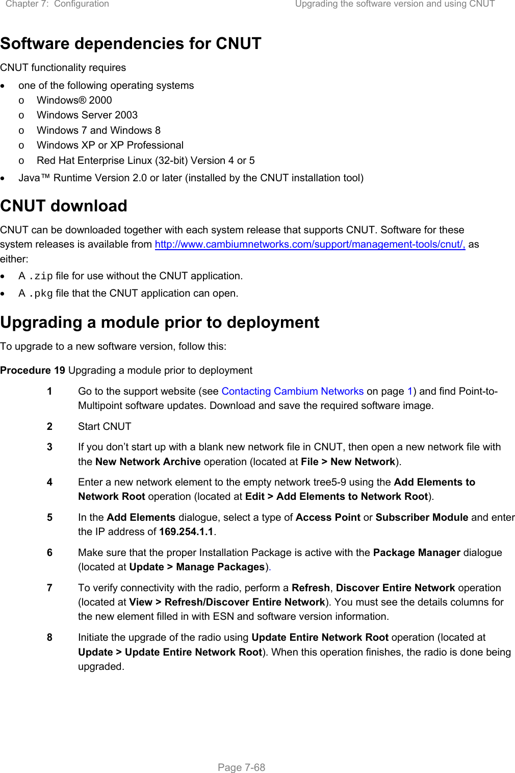
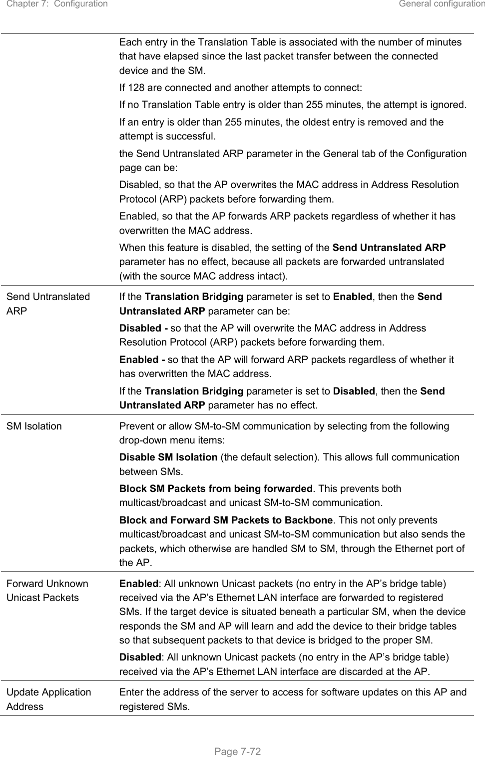
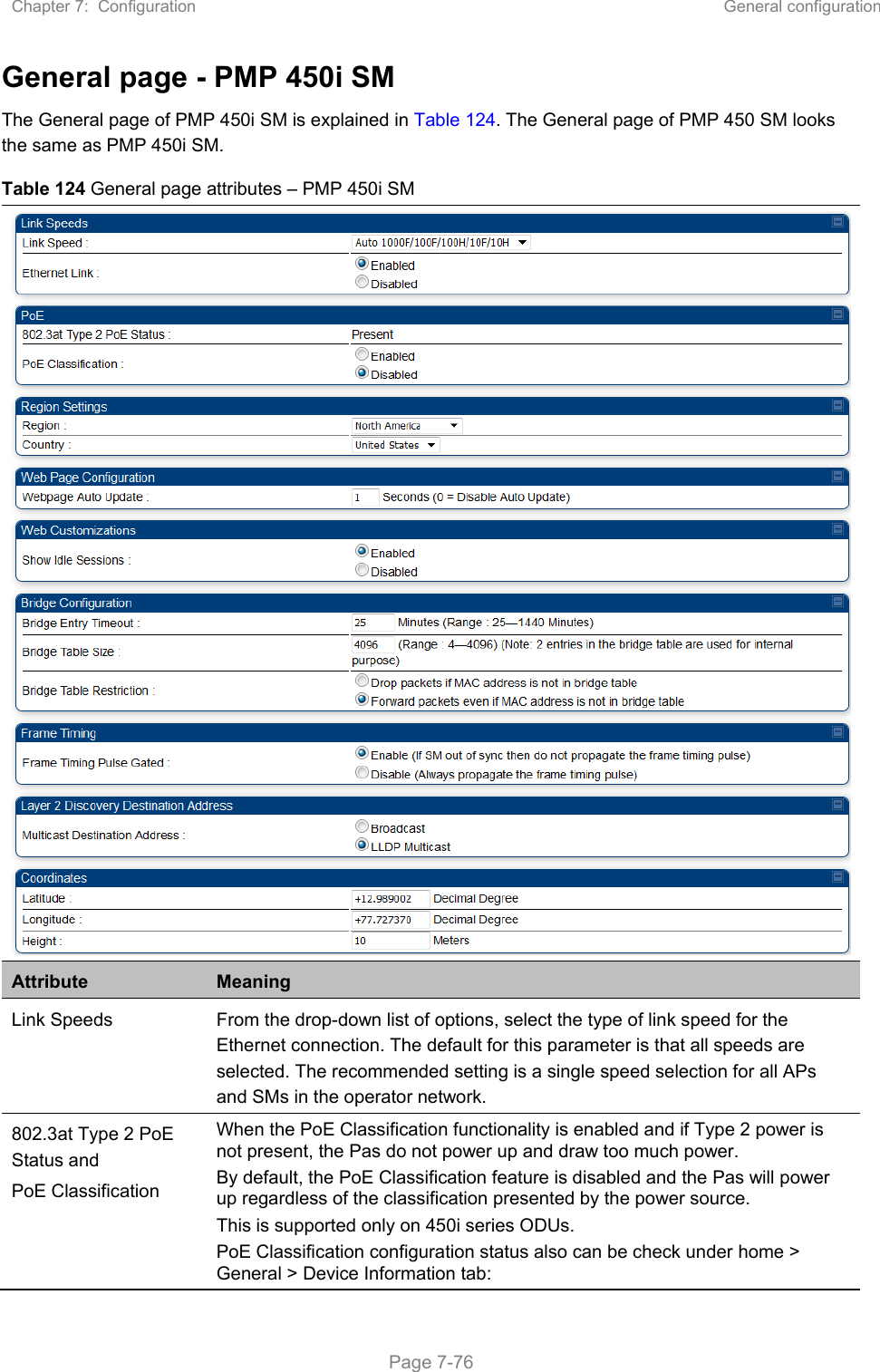
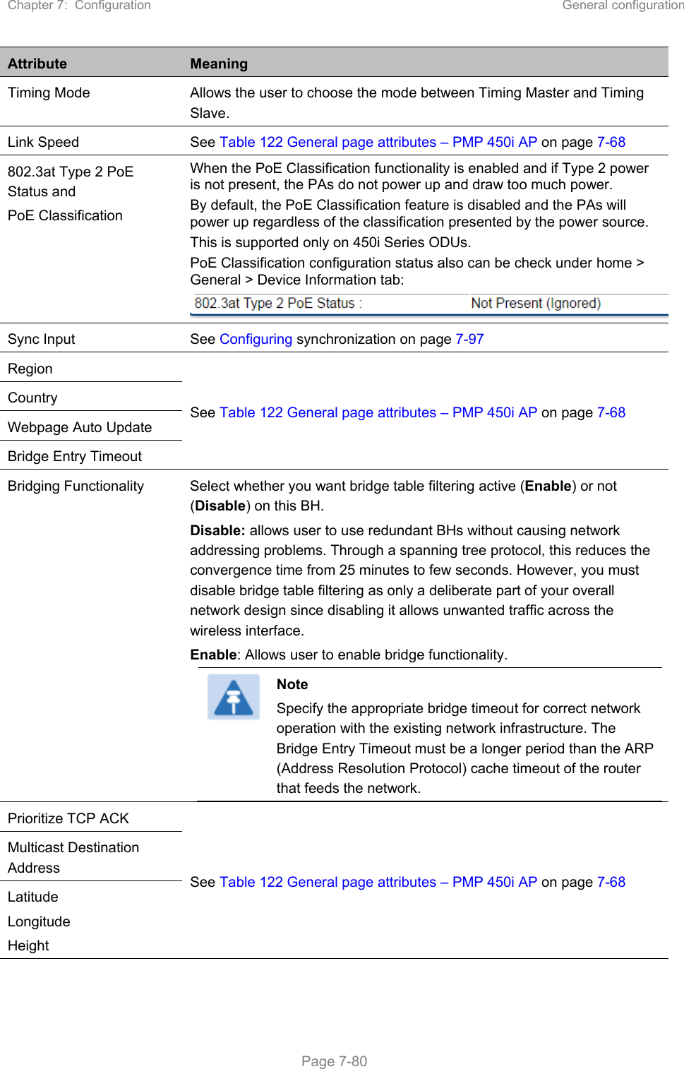
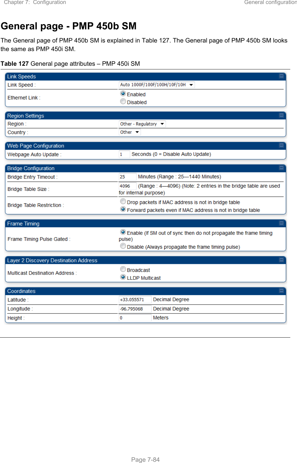
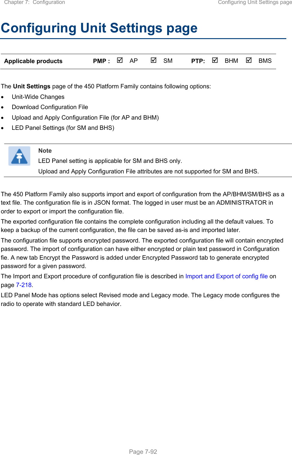
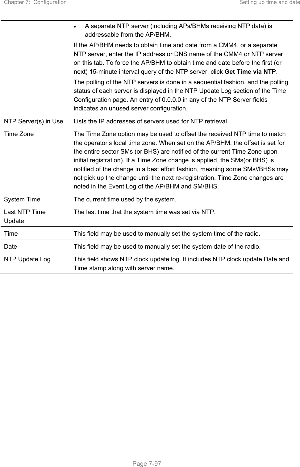
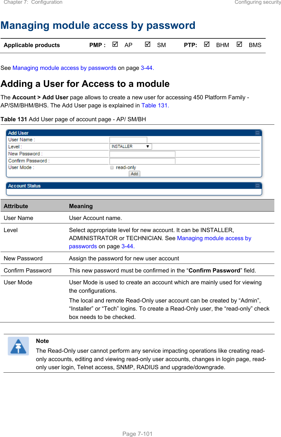
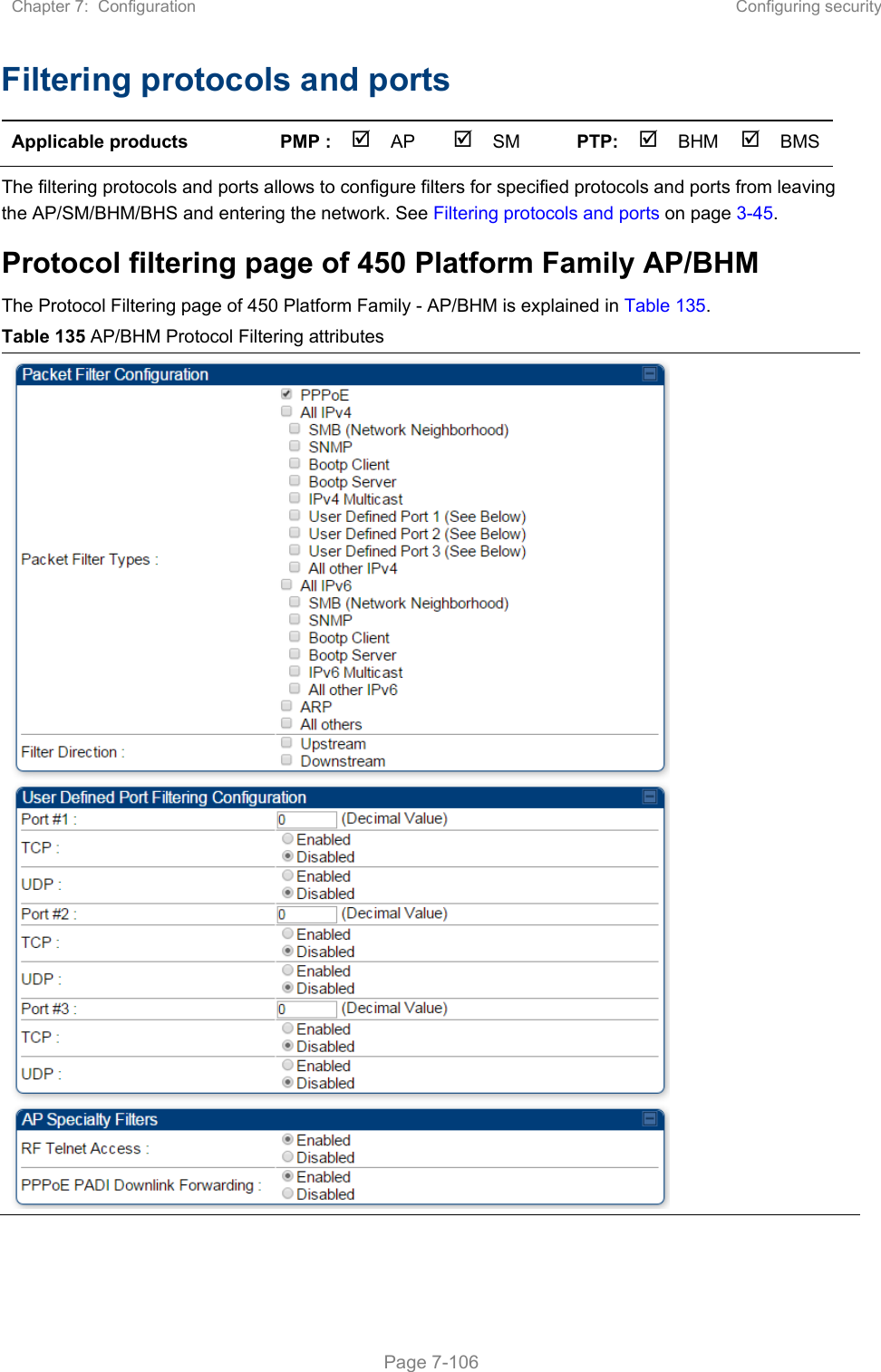
![Chapter 7: Configuration Configuring security Page 7-110 Filtering management through Ethernet See Filtering management through Ethernet on page 3-49. Allowing management only from specified IP addresses See Allowing management from only specified IP addresses on page 3-50. Restricting radio Telnet access over the RF interface RF Telnet Access restricts Telnet access to the AP from a device situated below a network SM (downstream from the AP). This is a security enhancement to restrict RF-interface sourced AP access specifically to the LAN1 IP address and LAN2 IP address (Radio Private Address, typically 192.168.101. [LUID]). This restriction disallows unauthorized users from running Telnet commands on the AP that can change AP configuration or modifying network-critical components such as routing and ARP tables. The RF Telnet Access may be configured via the AP GUI or via SNMP commands, and RF Telnet Access is set to “Enabled” by default. Once RF Telnet Access is set to “Disabled”, if there is a Telnet session attempt to the AP originating from a device situated below the SM (or any downstream device), the attempt is dropped. This also includes Telnet session attempts originated from the SM’s management interface (if a user has initiated a Telnet session to a SM and attempts to Telnet from the SM to the AP). In addition, if there are any active Telnet connections to the AP originating from a device situated below the SM (or any downstream device), the connection is dropped. This behavior must be considered if system administrators use Telnet downstream from an AP (from a registered SM) to modify system parameters. Setting RF Telnet Access to “Disabled” does not affect devices situated above the AP from accessing the AP via Telnet, including servers running the CNUT (Canopy Network Updater tool) application. Also, setting RF Telnet Access to “Disabled” does not affect any Telnet access into upstream devices (situated above or adjacent to the AP) through the AP (see Figure 140). The figure below depicts a user attempting two telnet sessions. One is targeted for the AP (orange) and one is targeted for the network upstream from the AP (green). If RF Telnet Access is set to “Disabled” (factory default setting), the Telnet attempt from the user to the AP is blocked, but the attempt from the user to Network is allowed to pass through the Cambium network. Figure 140 RF Telnet Access Restrictions (orange) and Flow through (green)](https://usermanual.wiki/Cambium-Networks/50450M.USERS-MANUAL-PART2/User-Guide-3650883-Page-127.png)