Cambium Networks 50450M 5 GHz Point to Multipoint User MIMO Accesspoint User Manual 450 Platform User Guide
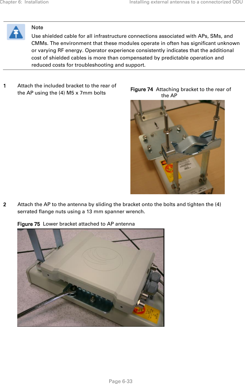
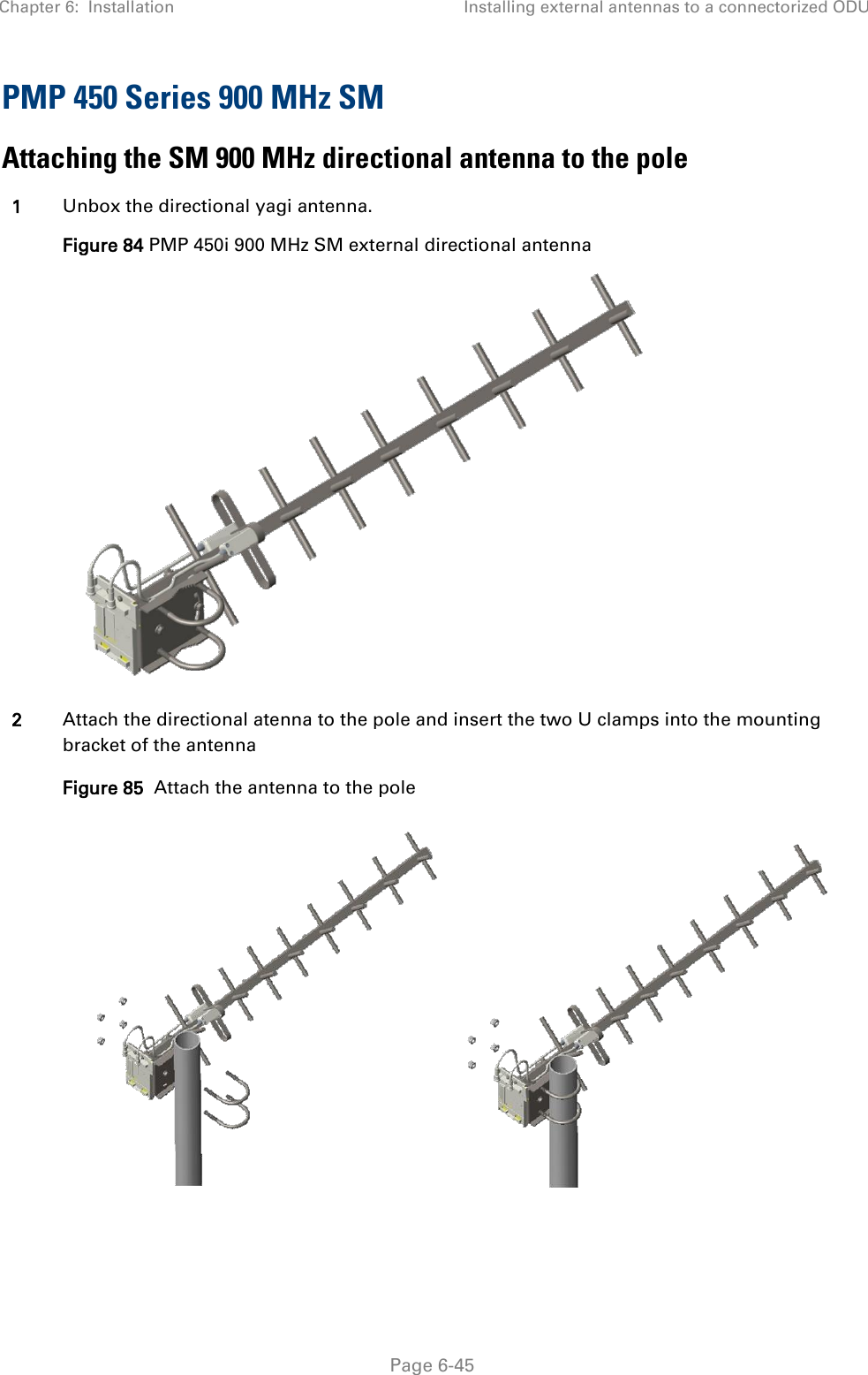
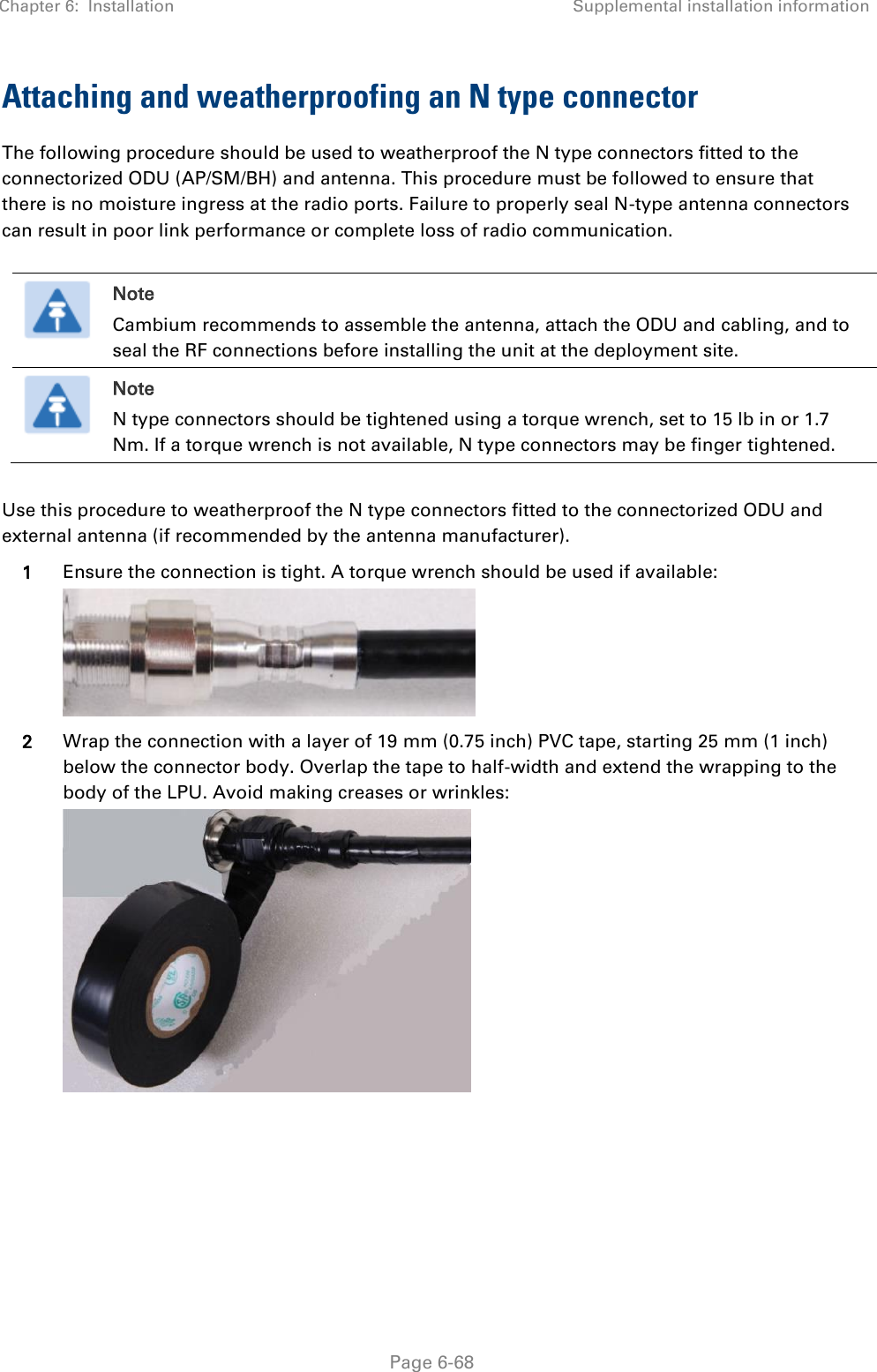
Cambium Networks Limited 5 GHz Point to Multipoint User MIMO Accesspoint 450 Platform User Guide
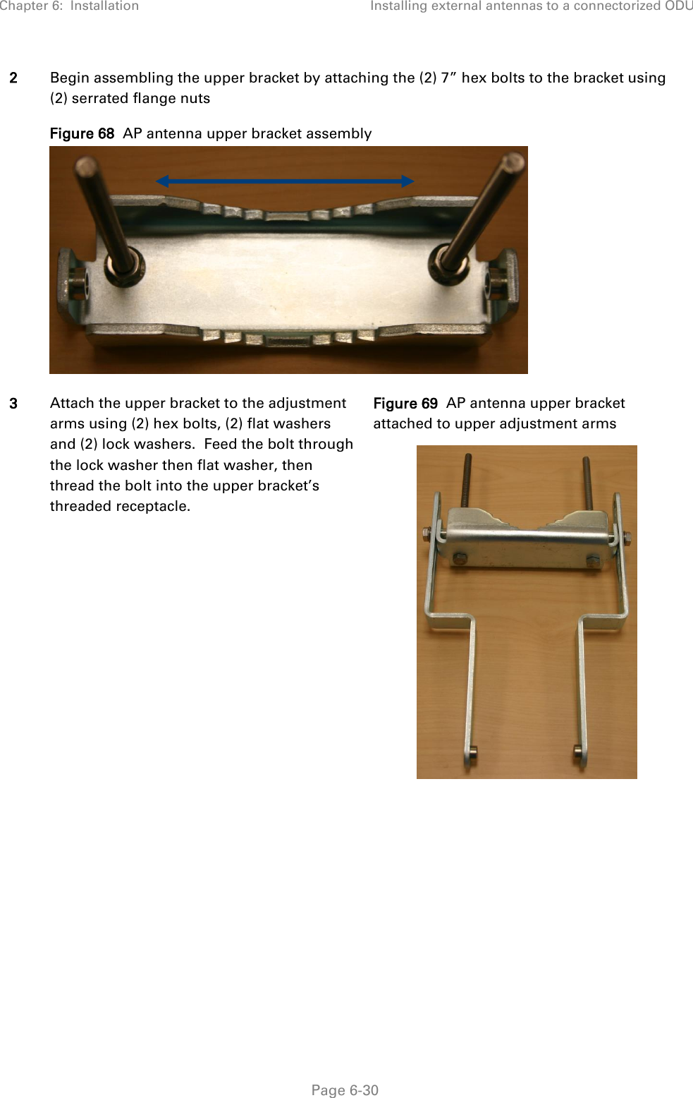
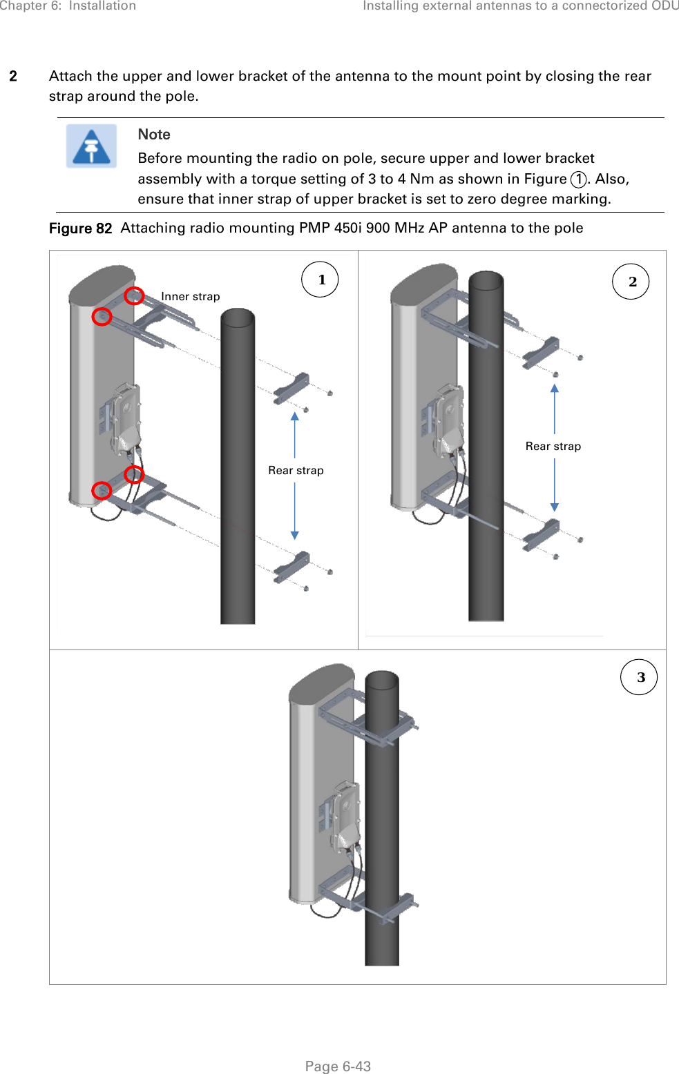
Contents
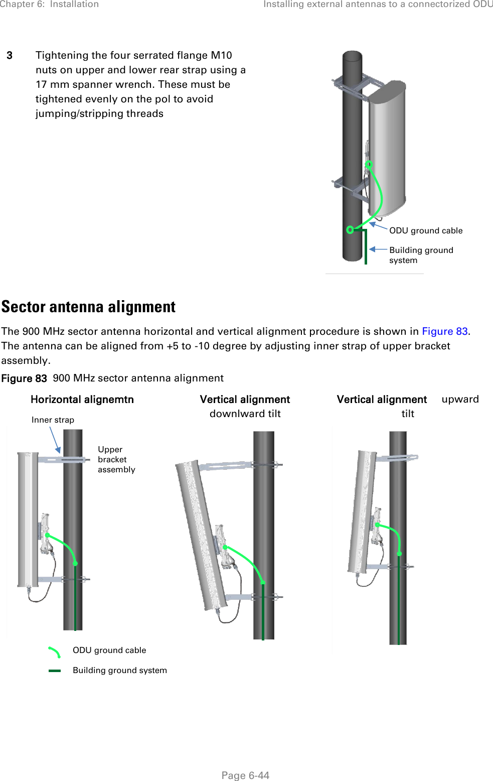
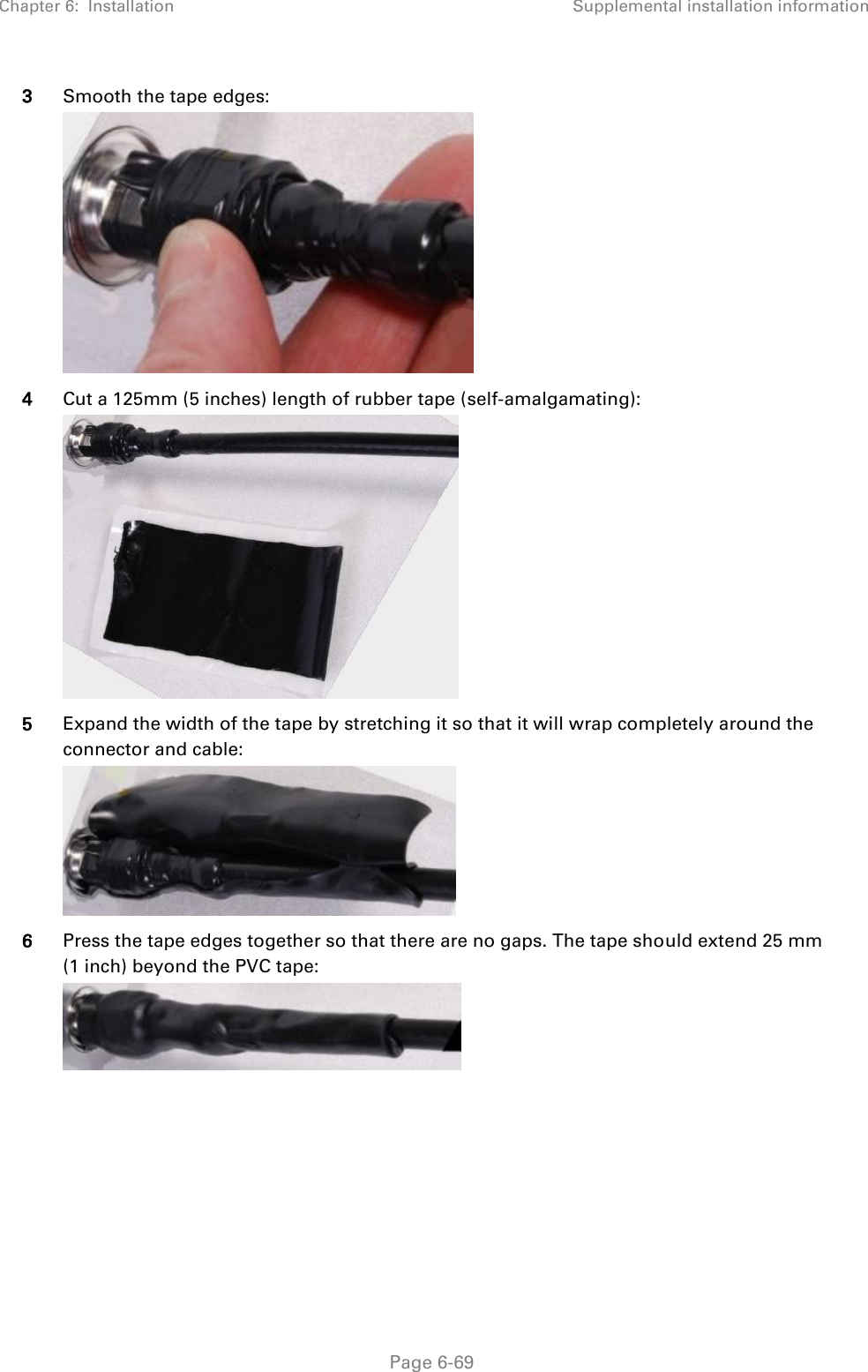
- 1. USER GUIDE P1
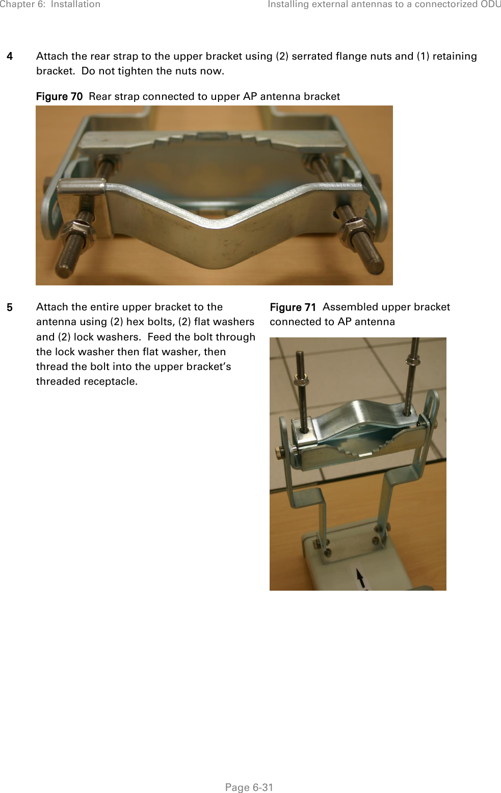
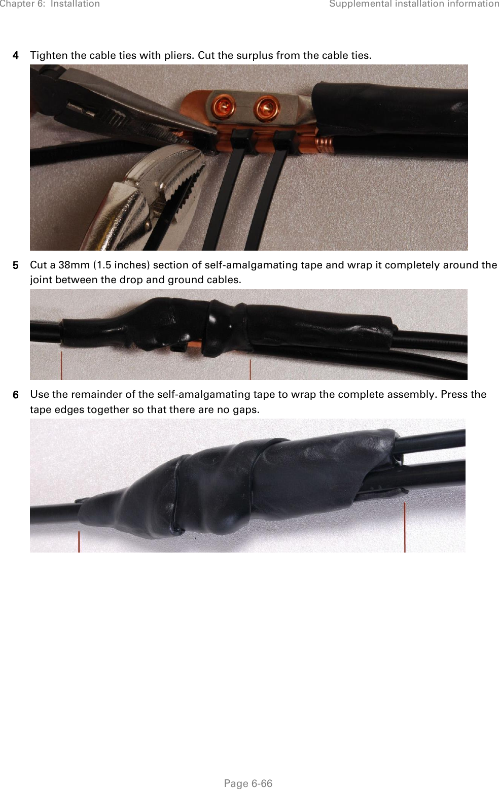
- 2. USER GUIDE P2
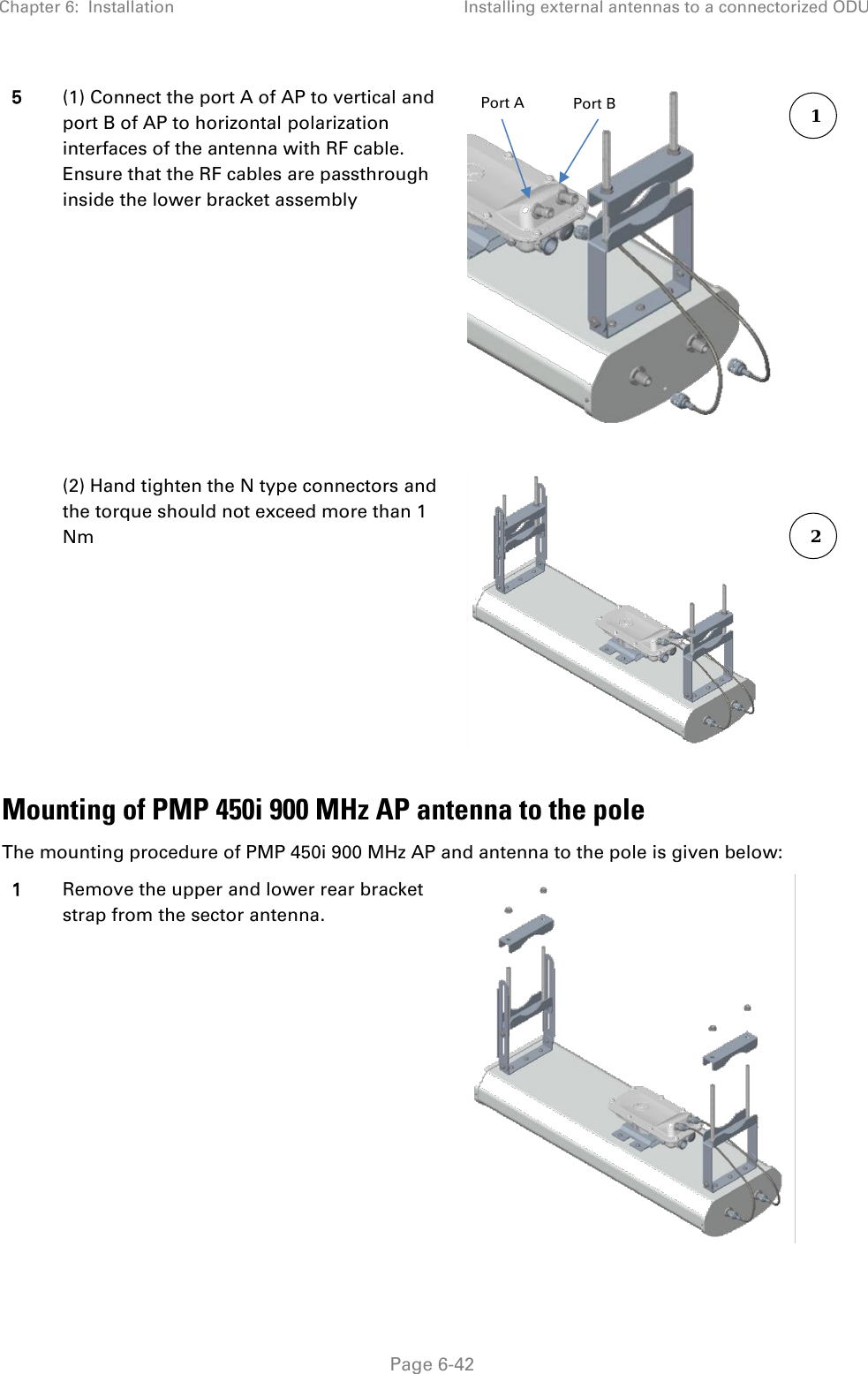
- 3. USER GUIDE P3
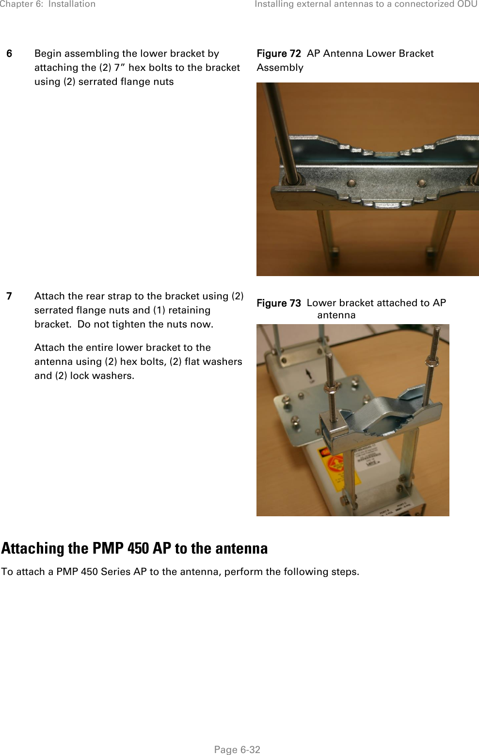
- 4. USER GUIDE P4
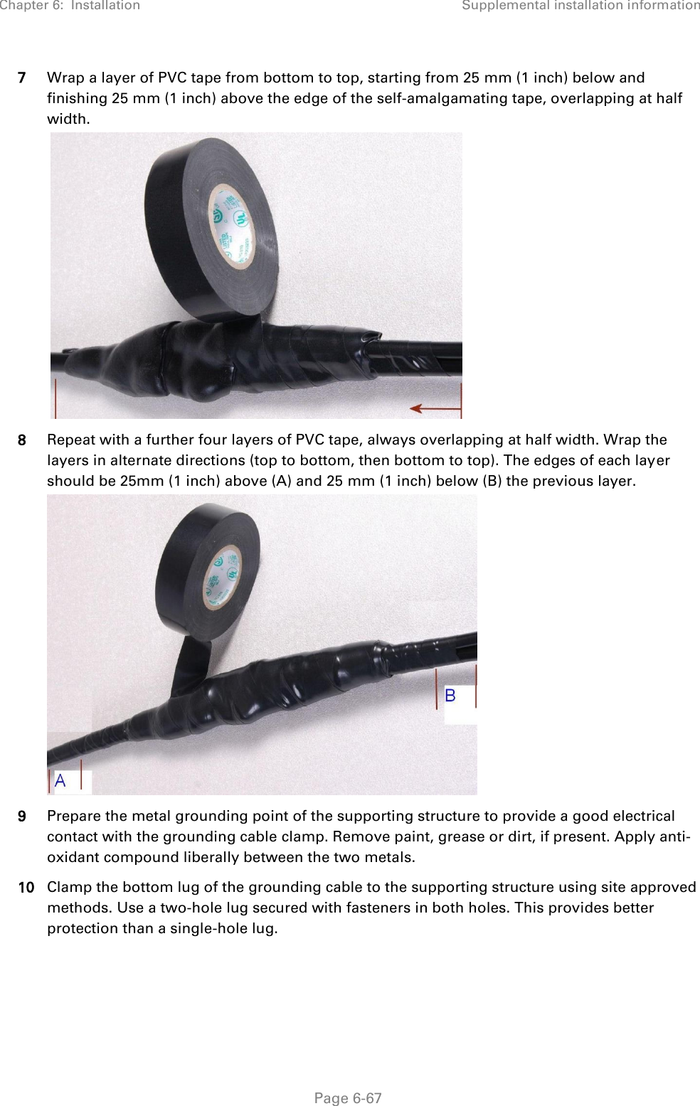
- 5. User manual
- 6. User Manual
- 7. USERS MANUAL PART1
- 8. USERS MANUAL PART2
- 9. USERS MANUAL PART3
- 10. USERS MANUAL PART4
- 11. USER MANUAL PART1
- 12. USER MANUAL PART2
- 13. USER MANUAL PART 3
- 14. USER MANUAL PART 4
- 15. USER MANUAL PT1
- 16. USER MANUAL PT2
- 17. USER MANUAL PT3
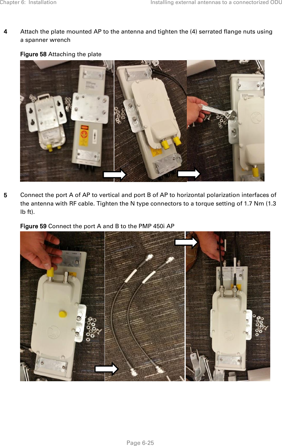
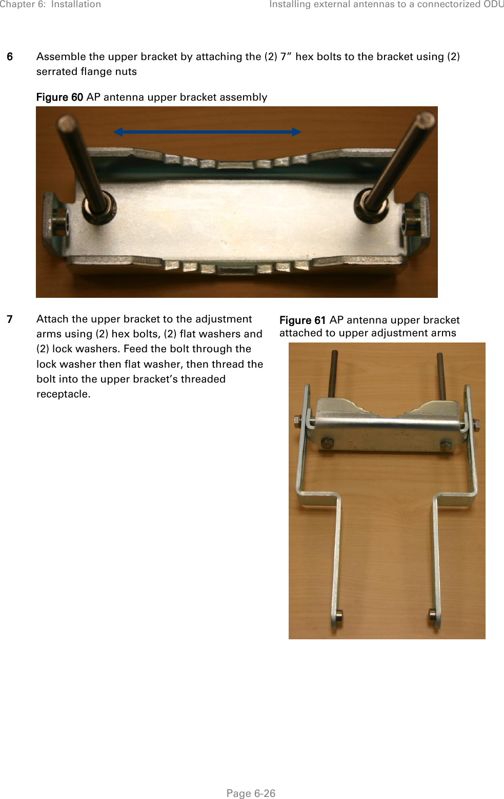
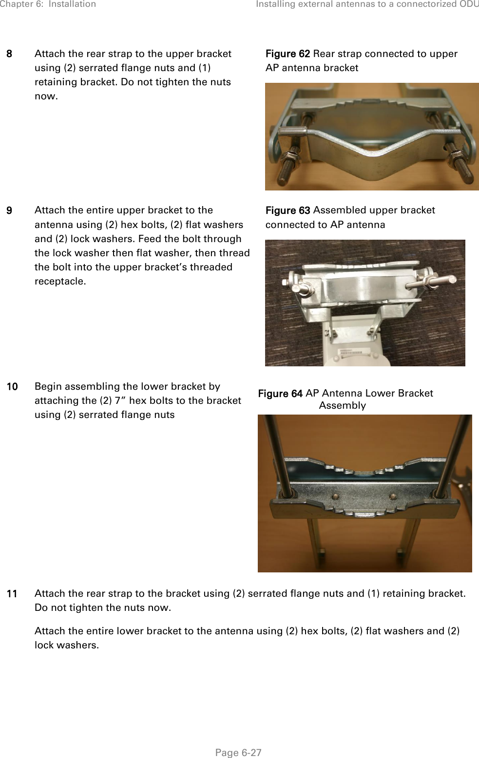
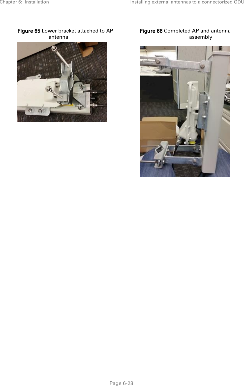
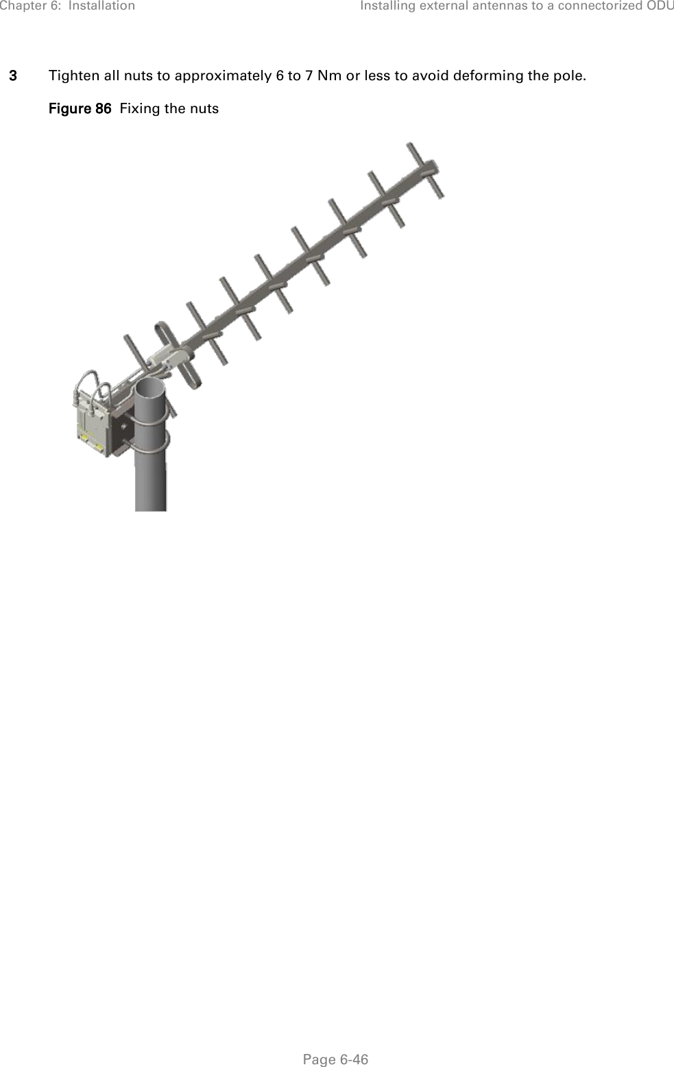
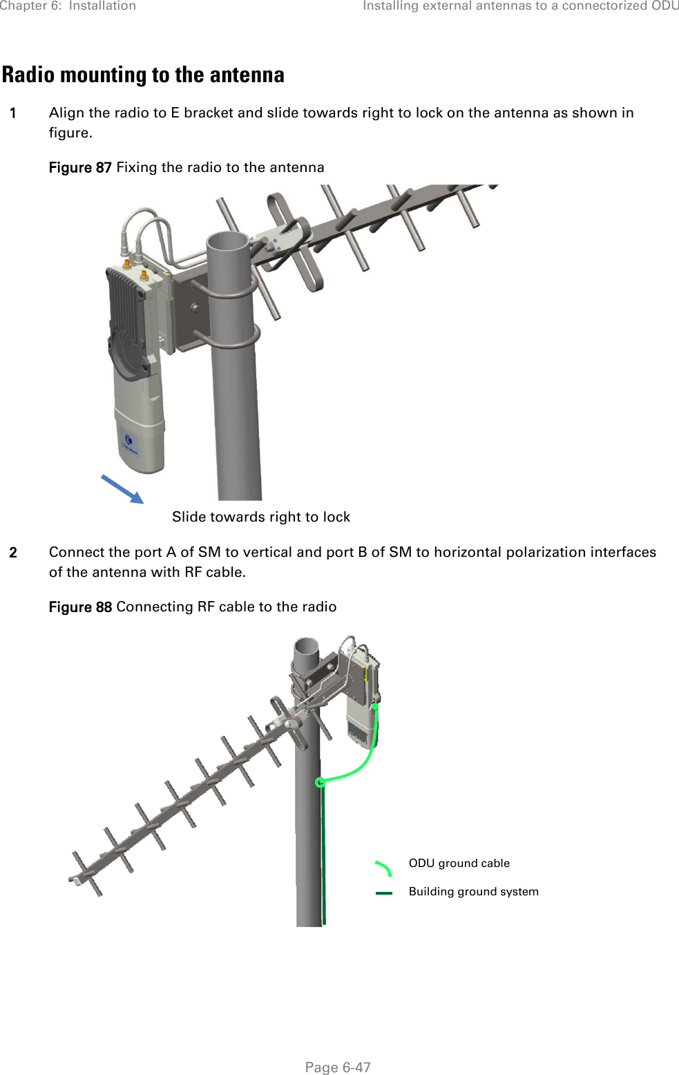
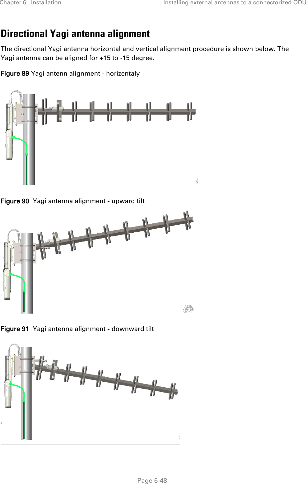
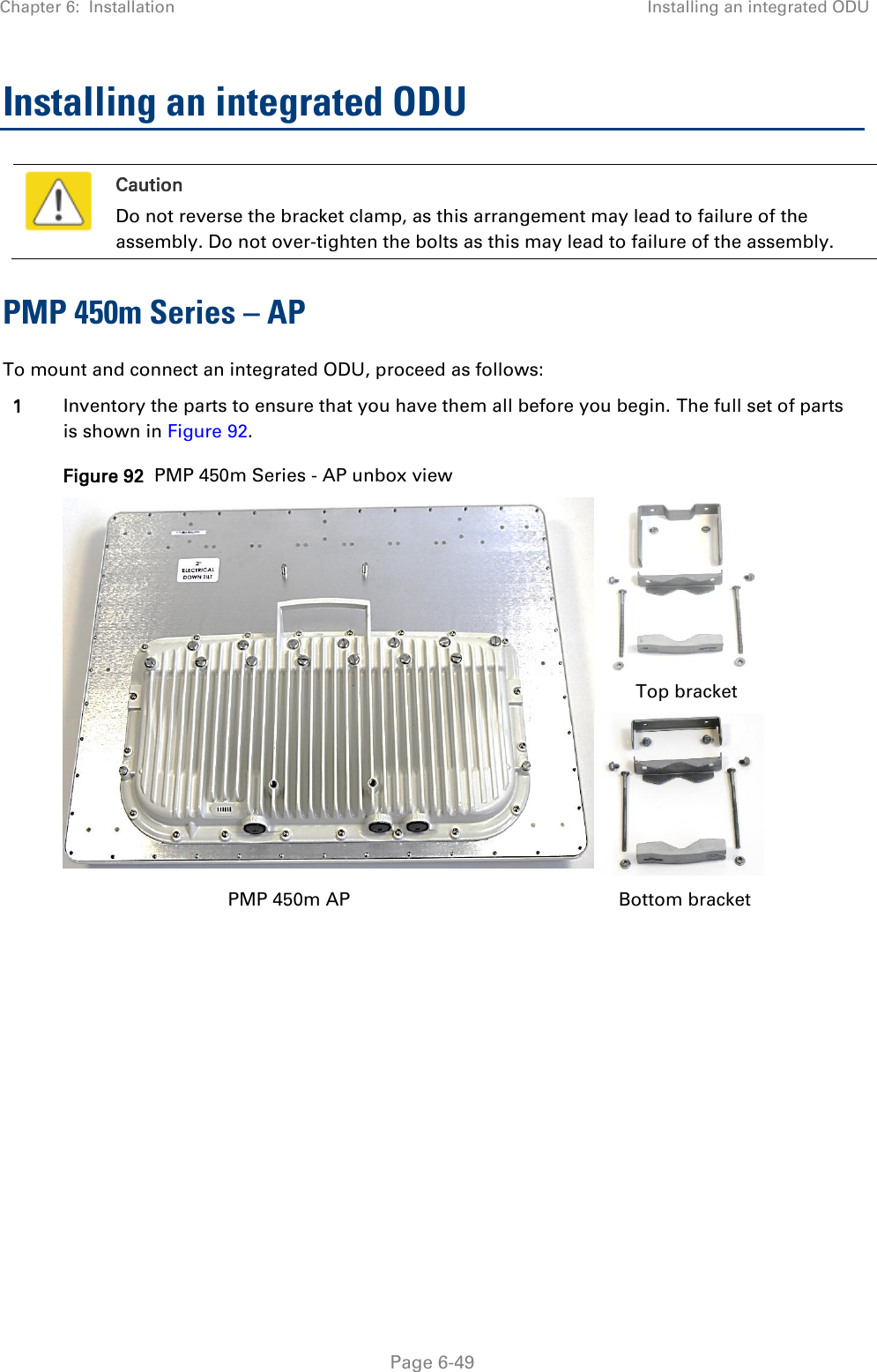
USER GUIDE P2