Cambium Networks 50450M 5 GHz Point to Multipoint User MIMO Accesspoint User Manual 450 Platform User Guide
Cambium Networks Limited 5 GHz Point to Multipoint User MIMO Accesspoint 450 Platform User Guide
Contents
- 1. USER GUIDE P1
- 2. USER GUIDE P2
- 3. USER GUIDE P3
- 4. USER GUIDE P4
- 5. User manual
- 6. User Manual
- 7. USERS MANUAL PART1
- 8. USERS MANUAL PART2
- 9. USERS MANUAL PART3
- 10. USERS MANUAL PART4
- 11. USER MANUAL PART1
- 12. USER MANUAL PART2
- 13. USER MANUAL PART 3
- 14. USER MANUAL PART 4
- 15. USER MANUAL PT1
- 16. USER MANUAL PT2
- 17. USER MANUAL PT3
USER GUIDE P2

Page 6-1
Chapter 6: Installation
This chapter describes how to install and test the hardware for a PMP/PTP 450 platform link. It
contains the following topics:
ODU variants and mounting bracket options on page 6-2 provides details of six different
bracket options, including the type of ODU and range of pole diameters supported by each
option.
Mount the ODU, LPU and surge suppressor on page 6-3 describes how to mount and ground
an integrated or connectorized ODU, how to mount and ground the top LPU.
Installing the copper Cat5e Ethernet interface on page 6-17 describes how to install the copper
Cat5e power over Ethernet interface from the ODU to the PSU.
Installing external antennas to a connectorized ODU on page 6-21 describes how to install
external antennas for a connectorized ODU.
Installing ODU on page 6-56 describes how to install PTP and PMP ODU radios.
Installing the AC Power Injector on page 6-61 describes how to install a power supply unit for
the PMP/PTP 450 platform, either the AC Power Injector.
Supplemental installation information on page 6-64 contains detailed installation procedures
that are not included in the above topics, such as how to strip cables, create grounding points
and weatherproof connectors.
Note
These instructions assume that LPUs are being installed from the PMP/PTP 450
platform LPU and grounding kit (Cambium part number C000065L007). If the
installation does not require LPUs, adapt these instructions as appropriate.
If LPUs are being installed, only use the five black-capped EMC cable glands supplied
in the LPU and grounding kit. The silver-capped cable glands supplied in the ODU kits
must only be used in PMP/PTP 450 platform installations which do not require LPUs.

Chapter 6: Installation
ODU variants and mounting bracket options
Page 6-2
ODU variants and mounting bracket options
Mounting bracket– PMP/PTP 450i
The PMP/PTP 450i series supports below mentioned mounting bracket option:
Table 81 PMP/PTP 450i ODU mounting bracket part numbers
Cambium description
Cambium part number
Mounting bracket – low profile adjustable
N000045L002A
The low profile bracket provides elevation adjustment with the PMP/PTP 450i Integrated ODUs of
+10° to –5° or +5° to –10°. A larger adjustment range is available using the standard integrated
mounting bracket. The connectorized mounting bracket does not provide elevation adjustment.
Mounting bracket– PMP 450 900 MHz SM
The PMP 450i 900 MHz SM has special mounting bracket option. The PMP 450i 900 MHz AP
mounting procedure is the same as the other 450i radios. The 900 450 SM has a different
mounting bracket which is supplied along with yagi antenna.
Chapter 6: Installation
Mount the ODU, LPU and surge suppressor
Page 6-3
Mount the ODU, LPU and surge suppressor
To install the ODU and top LPU, use the following procedures:
Attach ground cables to the ODU on page 6-3
Mount the ODU on the mast on page 6-6
Mount the top LPU on page 6-9
Mount the Surge Suppressor on page 6-9
Attach ground cables to the ODU
PMP 450m Series – AP
1
Fasten an AWG 10 (or 6mm2) copper ground
cable to each ODU grounding point using the
M6 (small) lugs.
2
Tighten the Ground post screws.
3
Securely connect the copper wires to the
grounding system (Protective Earth) and the
LPU or Gigabit Ethernet Surge Suppressor
according to applicable regulations.
Chapter 6: Installation
Mount the ODU, LPU and surge suppressor
Page 6-4
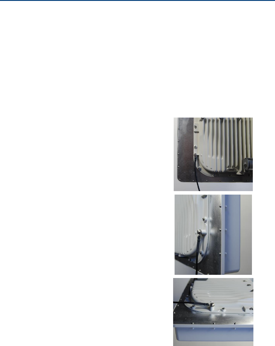
PMP/PTP 450i Series – AP/SM/BH, PMP 450 3GHz Ruggedized SM
1
Fasten an AWG 10 (or 6mm2) copper ground
cable to each ODU grounding point using the
M6 (small) lugs.
2
Tighten the Ground post screws.
3
Securely connect the copper wires to the grounding system (Protective Earth) and the LPU or
Gigabit Ethernet Surge Suppressor according to applicable regulations.
2
1
Chapter 6: Installation
Mount the ODU, LPU and surge suppressor
Page 6-5
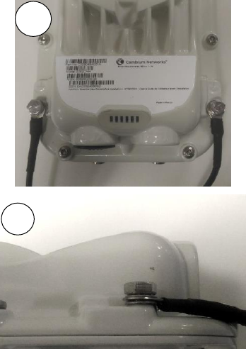
PMP 450 AP
1
Fasten an AWG 10 (or 6mm2) copper ground
cable to each ODU grounding point using the
M6 (small) lugs
2
Tighten the Ground post locking nut in the
copper wire
3
Securely connect the copper wire to the grounding system (Protective Earth) according to
applicable regulations.
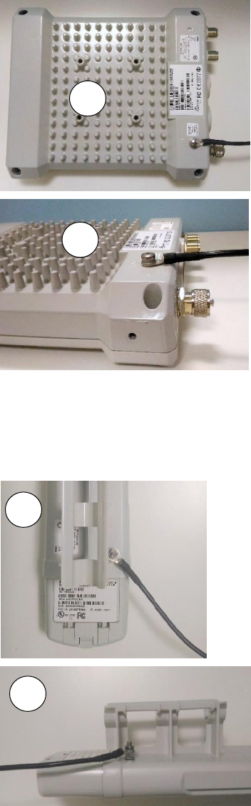
PMP 450 SM
1
Fasten an AWG 10 (or 6mm2) copper ground
cable to each ODU grounding point using the
M6 (small) lugs
2
Tighten the Ground post locking nut in the
copper wire
1
2
1
2
Chapter 6: Installation
Mount the ODU, LPU and surge suppressor
Page 6-6
3
Securely connect the copper wire to the grounding system (Protective Earth) according to
applicable regulations.
The grounding point on PMP 450 900 MHz SM is different from 2.4, 3.5/3.65 and 5 GHz PMP 450
SMs as shown in Figure 47.
Figure 47 PMP 450 900 MHz SM grounding
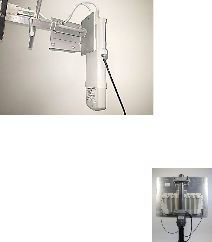
Mount the ODU on the mast
PMP 450m Series – AP
1
See - PMP 450m Series – AP on page 6-49 for Installion
for an integrated ODU
2
Remove the rear bracket strap from upper and lower
brackets of ODU
3
Attach the upper and lower bracket of ODU to the
mount point by closing the rear strap around the pole
4
Tighten the four serrated flange M10 nuts on upper
and lower rear strap using a 17 mm spanner wrench.
These must be tightened evenly on the pol to avoid
jumping/stripping threads
Chapter 6: Installation
Mount the ODU, LPU and surge suppressor
Page 6-7
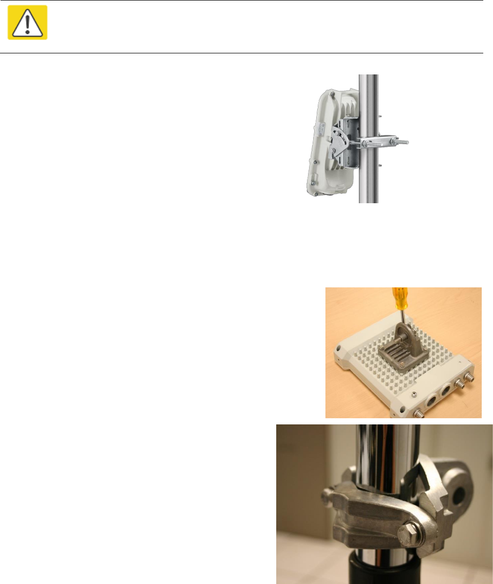
PMP/PTP 450i Series – AP/SM/BH, PMP 450 3 GHz Ruggedized SM
Caution
Do not reverse the bracket clamp, as this arrangement may lead to failure of the
assembly. Do not over-tighten the bolts as this may lead to failure of the assembly.
1
Fix the mounting plate to the back of the ODU using
the four bolts, and spring and plain washers provided.
Tighten the bolts.
2
Attach the bracket body to the mounting plate using
the M8 bolt, spring and plain washers.
3
Hoist the ODU to the mounting position
4
Attach the bracket body to the pole using the bracket
clamp, M8 bolts, and spring and plain washers.
5
Adjust the elevation and azimuth to achieve visual
alignment.
PMP 450 AP
1
Using an 8mm nut driver, attach the pole mount’s
AP housing bracket to the unit using the 4 M5 x
16mm bolts included with the AP.
2
Using the included (depending on pole diameter):
M8 x 70mm hex cap bolts ( 2 quantity)
or
M8 x 40mm hex cap bolts ( 2 quantity)
and
M8 flat washers ( 2 quantity)
M8 coil washers ( 2 quantity)
Attach the mounting bracket to the pole/mast.
The mounting bracket is designed to attach to
poles with diameters in the range of 2 in. (50mm)
to 3in. (75mm).
Chapter 6: Installation
Mount the ODU, LPU and surge suppressor
Page 6-8
3
Complete the AP mounting assembly by attaching
the included:
8mm hex cap bolt ( one quantity)
Through the AP’s attached mounting bracket and
pole mount. At this time the AP may be adjusted
to the desired position and tightened with a 1/2
inch spanner wrench to 11 lb/ft (14Nm).
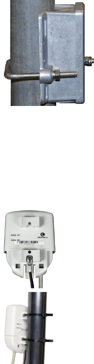
PMP 450 SM (except PMP 450 SM - 900 MHz)
1
Use stainless steel hose clamps for the
attachment.
2
Attach the mounting bracket to the structure.
Tighten the locking nut.
PMP 450 900 MHz SM (connectorized)
The PMP 450 900 MHz connectorized SM mounting procedure is different from other radios. It
does not get directly mounted on pole.
1
Align the 900 MHz SM to E bracket
of Yagi antenna
2
Slide the radio towards right to
lock on the antenna
Stainless steel
hose clamps
Reflector dish arm
Slide towards right to lock
Chapter 6: Installation
Mount the ODU, LPU and surge suppressor
Page 6-9
Mount the top LPU
1
For separate LPU mounting, use the U-bolt
bracket from the LPU kit to mount the top LPU
on the pole below the ODU. Tighten to a torque
setting of 7.0 Nm (5.2 lb ft).
Please refer Gigabit LPU and Grounding Kit
Installation Guide for more details.
Mount the Surge Suppressor
PMP/PTP 450i Series
Gigabit Ethernet Surge Suppressors are installed at both ends of the drop cable. One within 600
mm (24”) space of and under the ODU. The other located within 600 mm (24”) space of the
building entry point.
Quick procedure:
The quick procedure for the Surge Suppressor for PMP/PTP 450i Series mounting is as follows:
1
Ground using the terminal on the back of the
units. Use the supplied Tubular Lug and 6 mm2
(10 AWG) stranded cable, max length 600 mm
(24”).
I. Waterproof the cable lug with heat
shrink sleeving.
II. Secure the Cable assembly to the unit using
the supplied screw and washer.
2
Mounting the Gigabit Ethernet Surge Suppressor
on wall or pole
Chapter 6: Installation
Mount the ODU, LPU and surge suppressor
Page 6-10
3
Connecting the two CAT5e cables to the Gigabit
Ethernet Surge Suppressor
4
Slide the end cap over the bottom of the Gigabit
Surge Suppressor, ensuring it clicks firmly in
place
Please refer Gigabit Ethernet Surge Suppressor Installation Guide for more details.
Figure 48 Gigabit Surge Suppressor
Chapter 6: Installation
Mount the ODU, LPU and surge suppressor
Page 6-11
PMP/PTP 450 Series
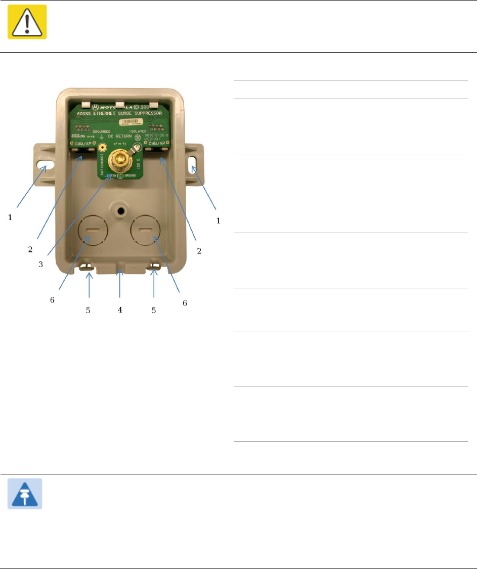
The PMP/PTP 450 Series uses 600SSH Surge Suppressor. The inside of the surge suppressor is
shown in Figure 49.
Caution
The PMP 450 900 MHz SM is based off the 450 platform, be sure to use a 600SS to
protect this radio type.
Figure 49 600SSH Surge Suppressor – inside
Key to Callouts 600SSH
1
Holes—for mounting the Surge
Suppressor to a flat surface (such as an
outside wall). The distance between
centers is 4.25 inches (108 mm).
2
RJ-45 connectors—One side (neither side
is better than the other for this purpose)
connects to the product (AP, SM, or
cluster management module). The other
connects to the AC adaptor’s Ethernet
connector.
3
Ground post and washer—use heavy
gauge (10 AWG or 6 mm2) copper wire for
connection. Refer to local electrical codes
for exact specifications.
4
Ground Cable Opening—route the 10
AWG (6 mm2) ground cable through this
opening.
5
CAT-5 Cable Knockouts—route the two
CAT-5 cables through these openings, or
alternatively through the Conduit
Knockouts.
6
Conduit Knockouts—on the back of the
case, near the bottom. Available for
installations where cable is routed
through building conduit.
Note
The 600SSH surge suppressor is shipped in the “isolated” position (pin 4 isolated by
68V from protective earth). If packet error issues occur over the Ethernet link (verify by
pinging the device through the 600SSH), configure the 600SSH to “grounded”
position (by moving the 600SSH switch from “isolated” to “ground”) to avoid ground
loops that may be present in the system.
Chapter 6: Installation
Mount the ODU, LPU and surge suppressor
Page 6-12
The mounting procedure for the Surge Suppressor for PMP/PTP 450 Series is as follows:
1
Remove the cover of the 600SSH Surge Suppressor.
2
With the cable openings facing downward, mount the 600SSH to the outside of the
subscriber premises, as close to the point where the Ethernet cable penetrates the residence
or building as possible, and as close to the grounding system (Protective Earth) as possible.
3
Wrap an AWG 10 (or 6mm2) copper wire around the Ground post of the 600SSH.
4
Tighten the Ground post locking nut in the 600SSH onto the copper wire.
5
Securely connect the copper wire to the grounding system (Protective Earth) according to
applicable regulations.
6
Using diagonal cutters or long nose pliers, remove the knockouts that cover the cable
openings to the 600SSH.
7
Pack both of the surge suppressor Ethernet jacks with dielectric grease.
8
Wrap an AWG 10 (or 6mm2) copper wire around the Ground post of the 600SSH.
9
Tighten the Ground post locking nut in the 600SSH onto the copper wire.
10
Securely connect the copper wire to the grounding system (Protective Earth) according to
applicable regulations.
11
Using diagonal cutters or long nose pliers, remove the knockouts that cover the cable
openings to the 600SSH.
12
Pack both of the surge suppressor Ethernet jacks with dielectric grease.
13
Wrap a splice loop in the loose end of the Ethernet cable from the SM.
14
Connect that cable to one of the Ethernet jacks.
15
Connect an Ethernet cable to the other Ethernet jack of the 600SSH and to the power adapter.
16
Replace the cover of the 600SSH.
General protection installation
To adequately protect a 450 platform installation, both ground bonding and transient voltage
surge suppression are required.
Basic requirements
The following basic protection requirements must be implemented:
ODU must be in ‘Zone B’ (see Lightning protection zones on page 3-9).
ODU must be grounded to the supporting structure.
A surge suppression unit must be installed on the outside of the building.
Chapter 6: Installation
Mount the ODU, LPU and surge suppressor
Page 6-13
The distance between the ODU and Gigabit Surge Suppressor should be kept to a minimum.
The drop cable must not be laid alongside a lightning air terminal.
All grounding cables must be a minimum size of 10 mm2 csa (8AWG), preferably 16 mm2 csa
(6AWG), or 25 mm2 csa (4AWG).
Grounding cable requirements
When routing, fastening and connecting grounding cables, the following requirements must be
implemented:
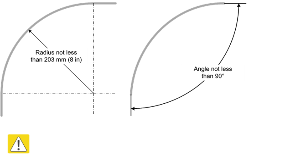
Grounding conductors must be run as short, straight, and smoothly as possible, with the
fewest possible number of bends and curves.
Grounding cables must not be installed with drip loops.
All bends must have a minimum radius of 203 mm (8 in) and a minimum angle of 90° (Figure
50). A diagonal run is preferable to a bend, even though it does not follow the contour or run
parallel to the supporting structure.
All bends, curves and connections must be routed towards the grounding electrode system,
ground rod, or ground bar.
Grounding conductors must be securely fastened.
Braided grounding conductors must not be used.
Approved bonding techniques must be used for the connection of dissimilar metals.
Figure 50 Grounding cable minimum bend radius and angle
Caution
Do not attach grounding cables to the ODU mounting bracket bolts, as this
arrangement will not provide full protection.
Chapter 6: Installation
Mount the ODU, LPU and surge suppressor
Page 6-14
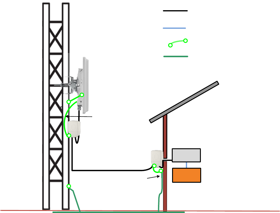
Protection requirements for a mast or tower installation
If the ODU is to be mounted on a metal tower or mast, then in addition to the general protection
requirements (above), the following requirements must be observed:
The equipment must be lower than the top of the tower or its lightning air terminal.
The metal tower or mast must be correctly grounded.
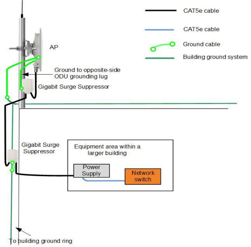
Schematic examples of mast or tower installations are shown in Figure 51.
Figure 51 Grounding and lightning protection on mast or tower
External
ground bar
Ground ring
Outdoor CAT5e cable
Power
supply
Equipment building
Network
switch
AP/BHM
Ground Cable
Tower/building ground system
Cat5e cable
Gigabit surge suppressor
Gigabit surge suppressor
Ground to opposite side
ODU grounding lug
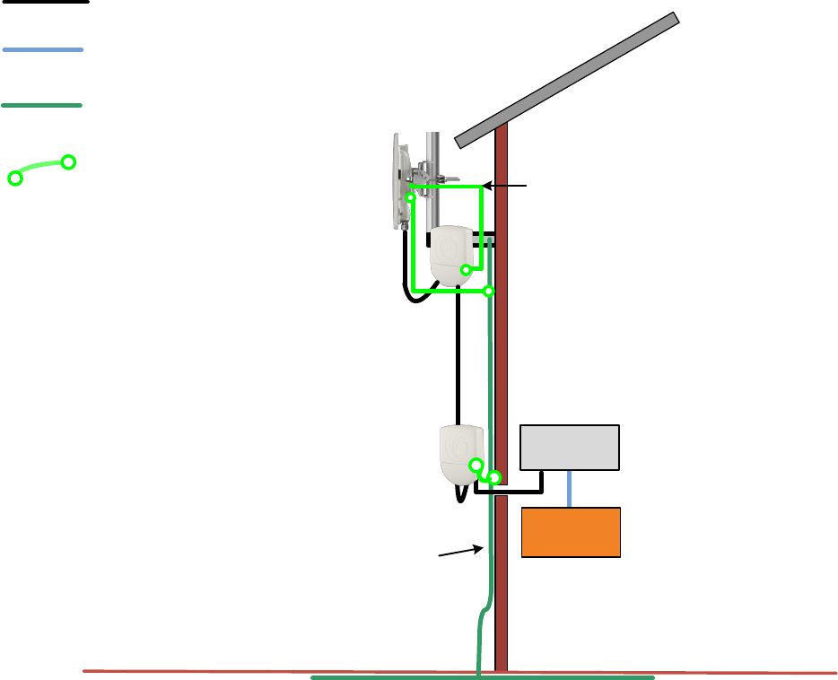
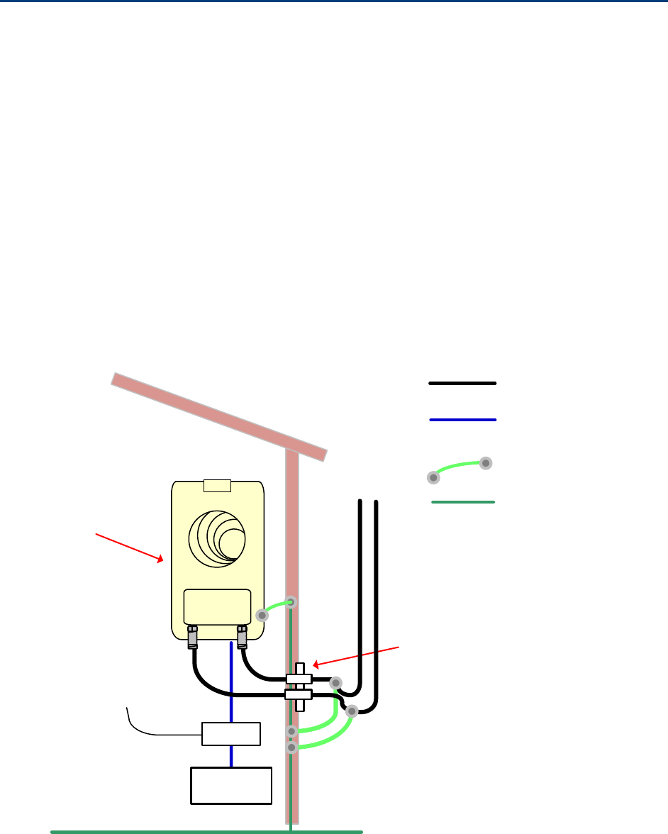
Protection requirements for a wall installation
If the ODU is to be mounted on the wall of a building, then in addition to the general protection
requirements (above), the following requirements must be observed:
The equipment must be lower than the top of the building or its lightning air terminal.
The building must be correctly grounded.
Chapter 6: Installation
Mount the ODU, LPU and surge suppressor
Page 6-15
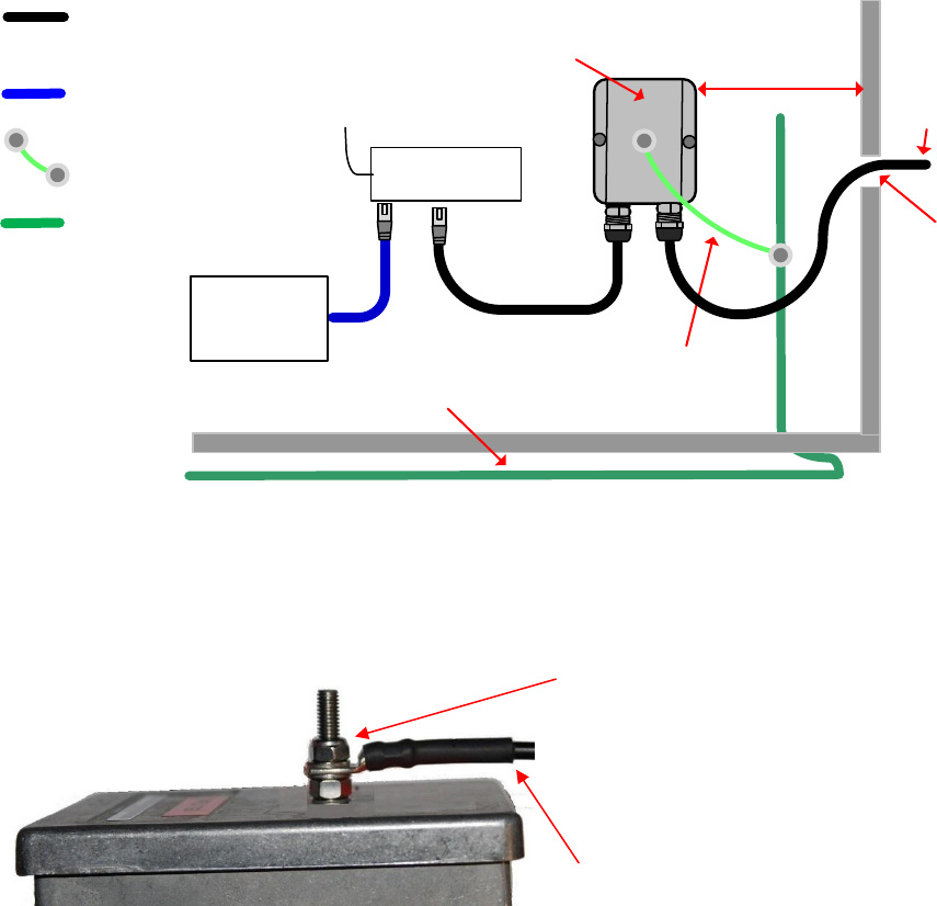
Schematic examples of wall installations are shown in Figure 52.
Figure 52 Grounding and lightning protection on wall
External
ground bar
Ground cable
Ground ring
Outdoor CAT5e cable
Power
Supply
Equipment building
Network
switch
Building ground system
SM/BHS
Cat5e cable
Gigabit Surge Suppressor
Gigabit Surge Suppressor
Ground to opposite-side
ODU grounding lug
Chapter 6: Installation
Mount the ODU, LPU and surge suppressor
Page 6-16
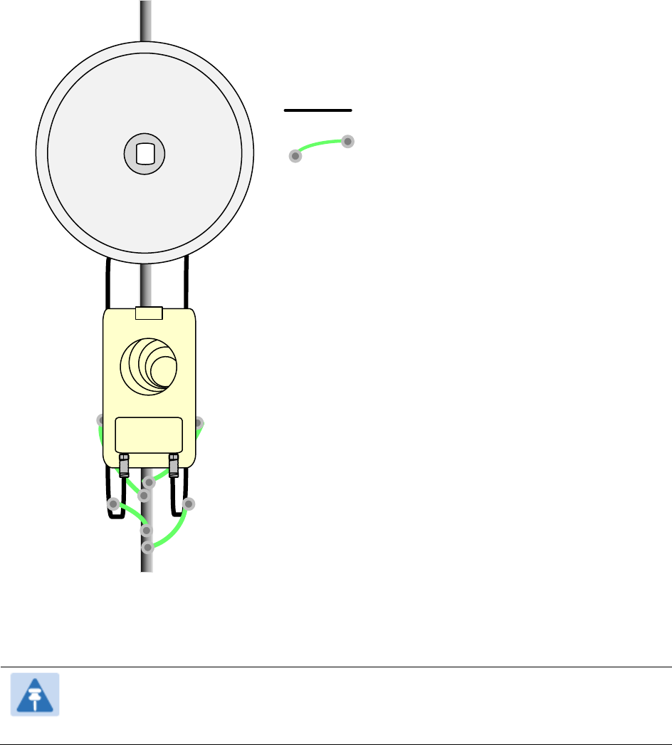
Protection requirements on a multifloor building
If the ODU is to be mounted on a high rise building, it is likely that cable entry is at roof level
(Figure 32) and the equipment room is several floors below. The following additional requirements
must be observed:
The ODU must be below the lightning terminals and finials.
A grounding conductor must be installed around the roof perimeter to form the main roof
perimeter lightning protection ring.
Air terminals are typically installed along the length of the main roof perimeter lightning
protection ring typically every 6.1m (20ft).
The main roof perimeter lightning protection ring must contain at least two down conductors
connected to the grounding electrode system. The down conductors should be physically
separated from one another, as far as practical.
Figure 53 Grounding and lightning protection on building
Chapter 6: Installation
Installing the copper Cat5e Ethernet interface
Page 6-17
Installing the copper Cat5e Ethernet interface
To install the copper Cat5e Ethernet interface, use the following procedures:
Install the main drop cable on page 6-17
Install the bottom LPU to PSU drop cable on page 6-19
Installing external antennas to a connectorized ODU on page 6-21
Caution
To avoid damage to the installation, do not connect or disconnect the drop cable when
power is applied to the PSU or network terminating equipment.
Caution
Always use Cat5e cable that is gel-filled and shielded with copper-plated steel.
Alternative types of Cat5e cable are not supported by Cambium Networks. Cambium
Networks supply this cable (Cambium part numbers WB3175 and WB3176), RJ45
connectors (Cambium part number WB3177) and a crimp tool (Cambium part number
WB3211). The LPU and grounding kit contains a 600 mm length of this cable.
Install the main drop cable
Warning
The metal screen of the drop cable is very sharp and may cause personal injury.
ALWAYS wear cut-resistant gloves (check the label to ensure they are cut resistant).
ALWAYS wear protective eyewear.
ALWAYS use a rotary blade tool to strip the cable (DO NOT use a bladed knife).
Warning
Failure to obey the following precautions may result in injury or death:
Use the proper hoisting grip for the cable being installed. If the wrong hoisting grip is
used, slippage or insufficient gripping strength will result.
Do not reuse hoisting grips. Used grips may have lost elasticity, stretched, or become
weakened. Reusing a grip can cause the cable to slip, break, or fall.
The minimum requirement is one hoisting grip for each 60 m (200 ft) of cable.
Chapter 6: Installation
Installing the copper Cat5e Ethernet interface
Page 6-18
Cut to length and fit hoisting grips
1
Cut the main drop cable to length from the top LPU to the bottom LPU.
2
Slide one or more hoisting grips onto the top end of the drop cable.
3
Secure the hoisting grip to the cable using a special tool, as recommended by the manufacturer.
Terminate with RJ45 connectors
Caution
Check that the crimp tool matches the RJ45 connector, otherwise the cable or
connector may be damaged.
1
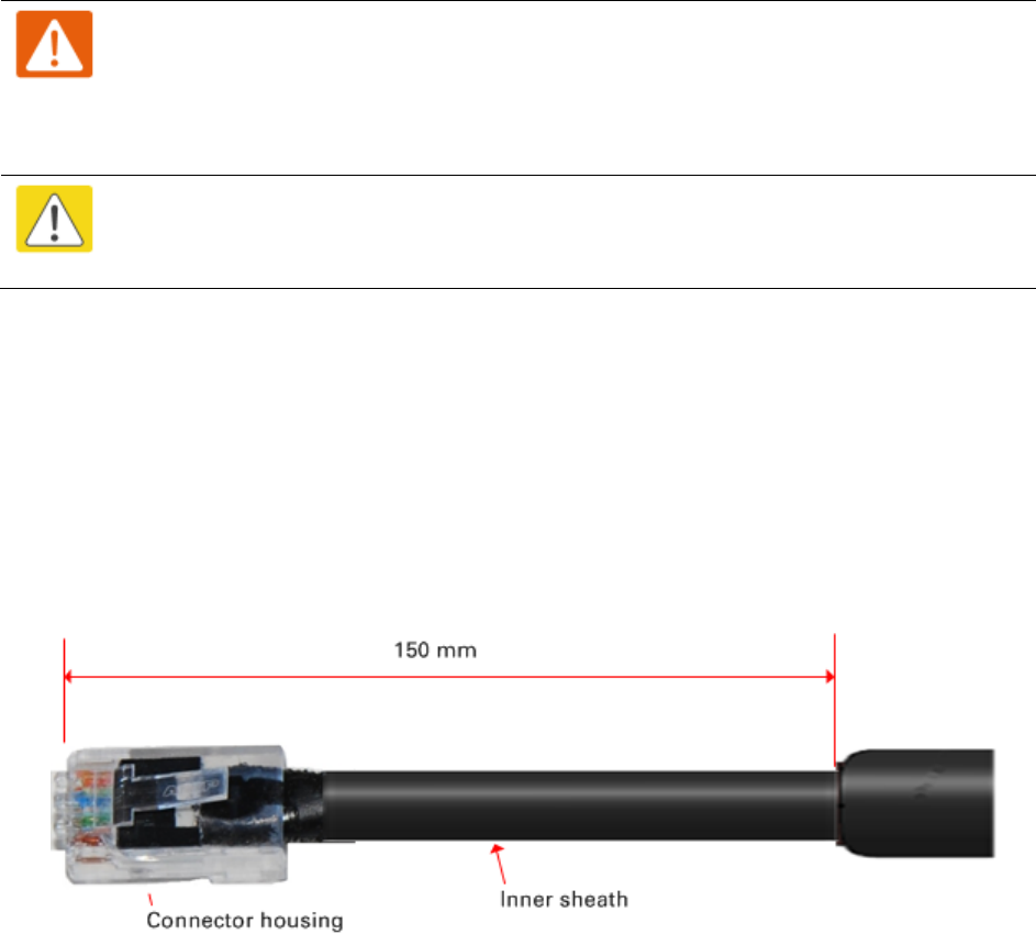
Strip the cable outer sheath and fit the RJ45 connector load bar.
2
Fit the RJ45 connector housing as shown. To ensure there is effective strain relief, locate the
cable inner sheath under the connector housing tang.
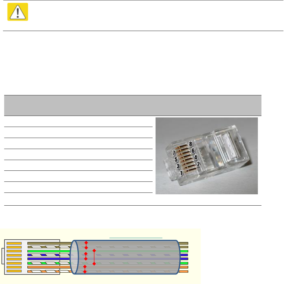
Table 82 RJ45 connector and cable color code
Pin
Color (Supplied
cable)
Color
(Conventional)
Pins on plug face
1
Light Orange
White/Orange
2
Orange
Orange
3
Light Green
White/Green
4
Blue
Blue
5
Light Blue
White/Blue
6
Green
Green
7
Light Brown
White/Brown
8
Brown
Brown
Figure 54 RJ45 cable
``
RJ45 Connector (Bottom)
Straight-Through Cable
8
7
6
5
4
3
2
1
Chapter 6: Installation
Installing the copper Cat5e Ethernet interface
Page 6-19
Install the bottom LPU to PSU drop cable
Install the bottom LPU
Install the bottom LPU, ground it, and connect it to the main drop cable.
1
Select a mounting point for the bottom LPU within 600 mm (24 in) of the building entry point.
Mount the LPU vertically with cable glands facing downwards.
Maximum 600 mm
(24 inches)
Bottom LPU
Grounding system
Building
entry
point
LPU to grounding system
PSU drop
cable
PSU
AC supply
Network
terminating
equipment
Ground cables
Power over Ethernet CAT5e
cable (gel-filled, shielded with
copper-plated steel)
Network CAT5e cable
Site grounding system
2
Connect the main drop cable to the bottom LPU.
3
Fasten one ground cable to the bottom LPU using the M6 (small) lug. Tighten both nuts to a
torque of 5 Nm (3.9 lb ft):
Locking nut
Washer
M6 lug
Washer
Nut
Toothed washer
M10 lug to ground
4
Select a building grounding point near the LPU bracket. Remove paint from the surface and
apply anti-oxidant compound. Fasten the LPU ground cable using the M10 (large) lug.
Chapter 6: Installation
Installing the copper Cat5e Ethernet interface
Page 6-20
Install the LPU to PSU drop cable
Use this procedure to terminate the bottom LPU to PSU drop cable with RJ45 connectors at both
ends, and with a cable gland at the LPU end.
Warning
The metal screen of the drop cable is very sharp and may cause personal injury.
ALWAYS wear cut-resistant gloves (check the label to ensure they are cut resistant).
ALWAYS wear protective eyewear. ALWAYS use a rotary blade tool to strip the cable,
not a bladed knife.
Caution
Check that the crimp tool matches the RJ45 connector, otherwise the cable or
connector may be damaged.
1
Cut the drop cable to the length required from bottom LPU to PSU.
2
At the LPU end only:
Fit one cable gland and one RJ45 connector by following the procedure Terminate with
RJ45 connectors on page 6-18.
Connect this cable and gland to the bottom LPU.
3
At the PSU end only: Do not fit a cable gland. Strip the cable outer sheath and fit the RJ45
connector load bar. Fit the RJ45 connector housing. To ensure there is effective strain relief,
locate the cable inner sheath under the connector housing tang:
Chapter 6: Installation
Installing external antennas to a connectorized ODU
Page 6-21
Installing external antennas to a connectorized ODU
PMP 450i Series
To mount and connect an external antenna to the connectorized ODU, proceed as follows:
1
Mount the antenna(s) according to manufacturer’s instructions.
2
Connect the ODU A and B interfaces to the antenna(s) with RF cable of type LMR-400 (Cambium
part numbers 30010194001 and 30010195001) and N type connectors (Cambium part number
09010091001). Tighten the N type connectors to a torque setting of 1.7 Nm (1.3 lb ft).
3
If the ODU is mounted indoors, install lightning arrestors at the building entry point:
4
Form drip loops near the lower ends of the antenna cables. These ensure that water is not
channeled towards the connectors.
5
If the ODU is mounted outdoors, weatherproof the N type connectors (when antenna alignment
is complete) using PVC tape and self-amalgamating rubber tape.
6
Weatherproof the antenna connectors in the same way (unless the antenna manufacturer
specifies a different method).
PSU
Network
equipment
CAT5e cable
Ground ring
RF cables to
antenna
AC supply
Lightning arrestors
Equipment building
or cabinet
RF cable
Connectorized
ODU
AB
Chapter 6: Installation
Installing external antennas to a connectorized ODU
Page 6-22
7
Ground the antenna cables to the supporting structure within 0.3 meters (1 foot) of the ODU and
antennas using the Cambium grounding kit (part number 01010419001):
Connectorized ODU
AB
PMP/PTP 450i ground
cable
RF cable
Antenna
8
Fix the antenna cables to the supporting structure using site approved methods. Ensure that no
undue strain is placed on the ODU or antenna connectors. Ensure that the cables do not flap in
the wind, as flapping cables are prone to damage and induce unwanted vibrations in the
supporting structure.
Note
A video on weatherproofing procedure can be found at:
https://www.youtube.com/watch?v=a-twPfCVq4A
Chapter 6: Installation
Installing external antennas to a connectorized ODU
Page 6-23
Assembling the PMP 450i 5.x GHz AP sector antenna and attaching to
the radio
To assemble a PMP 450i Series AP antenna, perform the following steps.
Note
Cambium recommends to assemble the antenna, attach the AP and cabling, and to
seal the RF connections before installing the unit at the deployment site.
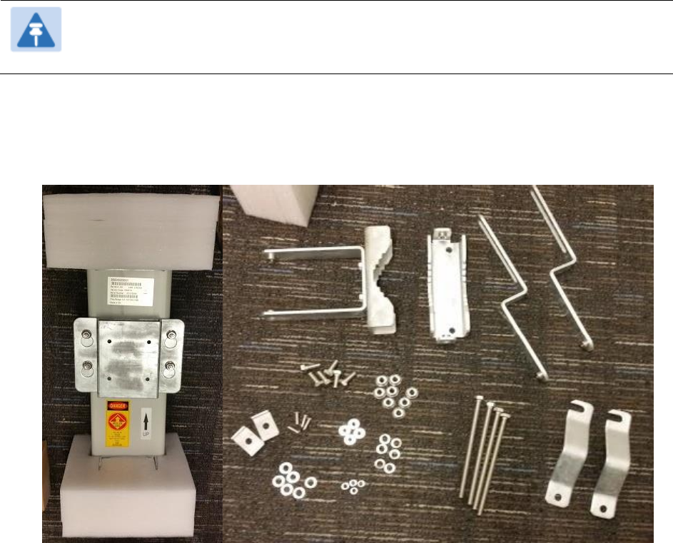
1
Inventory the parts to ensure that you have them all before you begin. The full set of parts
is shown below.
Figure 55 AP antenna parts
Chapter 6: Installation
Installing external antennas to a connectorized ODU
Page 6-24
2
Remove top plate from the antenna as shown in Figure 56.
Figure 56 Antenna top plate
3
Attach the antenna plate to the AP as shown in Figure 57.
Note
Please use the four “thin neck” M6 bolts and split washers provided with
the connectorized units rather that the ones provided in the antenna kit.
Figure 57 Attaching antenna plate to the AP
Chapter 6: Installation
Installing external antennas to a connectorized ODU
Page 6-25
4
Attach the plate mounted AP to the antenna and tighten the (4) serrated flange nuts using
a spanner wrench
Figure 58 Attaching the plate
5
Connect the port A of AP to vertical and port B of AP to horizontal polarization interfaces of
the antenna with RF cable. Tighten the N type connectors to a torque setting of 1.7 Nm (1.3
lb ft).
Figure 59 Connect the port A and B to the PMP 450i AP
Chapter 6: Installation
Installing external antennas to a connectorized ODU
Page 6-26
6
Assemble the upper bracket by attaching the (2) 7” hex bolts to the bracket using (2)
serrated flange nuts
Figure 60 AP antenna upper bracket assembly
7
Attach the upper bracket to the adjustment
arms using (2) hex bolts, (2) flat washers and
(2) lock washers. Feed the bolt through the
lock washer then flat washer, then thread the
bolt into the upper bracket’s threaded
receptacle.
Figure 61 AP antenna upper bracket
attached to upper adjustment arms
Chapter 6: Installation
Installing external antennas to a connectorized ODU
Page 6-27
8
Attach the rear strap to the upper bracket
using (2) serrated flange nuts and (1)
retaining bracket. Do not tighten the nuts
now.
Figure 62 Rear strap connected to upper
AP antenna bracket
9
Attach the entire upper bracket to the
antenna using (2) hex bolts, (2) flat washers
and (2) lock washers. Feed the bolt through
the lock washer then flat washer, then thread
the bolt into the upper bracket’s threaded
receptacle.
Figure 63 Assembled upper bracket
connected to AP antenna
10
Begin assembling the lower bracket by
attaching the (2) 7” hex bolts to the bracket
using (2) serrated flange nuts
Figure 64 AP Antenna Lower Bracket
Assembly
11
Attach the rear strap to the bracket using (2) serrated flange nuts and (1) retaining bracket.
Do not tighten the nuts now.
Attach the entire lower bracket to the antenna using (2) hex bolts, (2) flat washers and (2)
lock washers.
Chapter 6: Installation
Installing external antennas to a connectorized ODU
Page 6-28
Figure 65 Lower bracket attached to AP
antenna
Figure 66 Completed AP and antenna
assembly
Chapter 6: Installation
Installing external antennas to a connectorized ODU
Page 6-29
PMP 450 Series
Assembling the PMP 450 AP antenna
To assemble a PMP 450 Series AP antenna, perform the following steps.
Note
Cambium recommends to assemble the antenna, attach the AP and cabling, and to
seal the RF connections before installing the unit at the deployment site.
1
Inventory the parts to ensure that you have them all before you begin. The full set of parts
is shown below.
Figure 67 PMP 450 AP antenna parts
Chapter 6: Installation
Installing external antennas to a connectorized ODU
Page 6-30
2
Begin assembling the upper bracket by attaching the (2) 7” hex bolts to the bracket using
(2) serrated flange nuts
Figure 68 AP antenna upper bracket assembly
3
Attach the upper bracket to the adjustment
arms using (2) hex bolts, (2) flat washers
and (2) lock washers. Feed the bolt through
the lock washer then flat washer, then
thread the bolt into the upper bracket’s
threaded receptacle.
Figure 69 AP antenna upper bracket
attached to upper adjustment arms
Chapter 6: Installation
Installing external antennas to a connectorized ODU
Page 6-31
4
Attach the rear strap to the upper bracket using (2) serrated flange nuts and (1) retaining
bracket. Do not tighten the nuts now.
Figure 70 Rear strap connected to upper AP antenna bracket
5
Attach the entire upper bracket to the
antenna using (2) hex bolts, (2) flat washers
and (2) lock washers. Feed the bolt through
the lock washer then flat washer, then
thread the bolt into the upper bracket’s
threaded receptacle.
Figure 71 Assembled upper bracket
connected to AP antenna
Chapter 6: Installation
Installing external antennas to a connectorized ODU
Page 6-32
6
Begin assembling the lower bracket by
attaching the (2) 7” hex bolts to the bracket
using (2) serrated flange nuts
Figure 72 AP Antenna Lower Bracket
Assembly
7
Attach the rear strap to the bracket using (2)
serrated flange nuts and (1) retaining
bracket. Do not tighten the nuts now.
Attach the entire lower bracket to the
antenna using (2) hex bolts, (2) flat washers
and (2) lock washers.
Figure 73 Lower bracket attached to AP
antenna
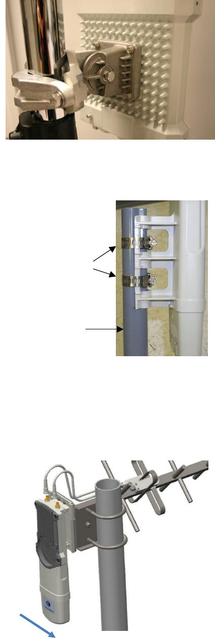
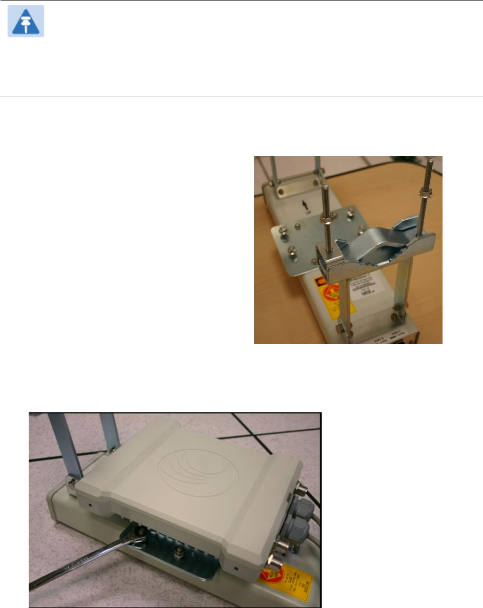
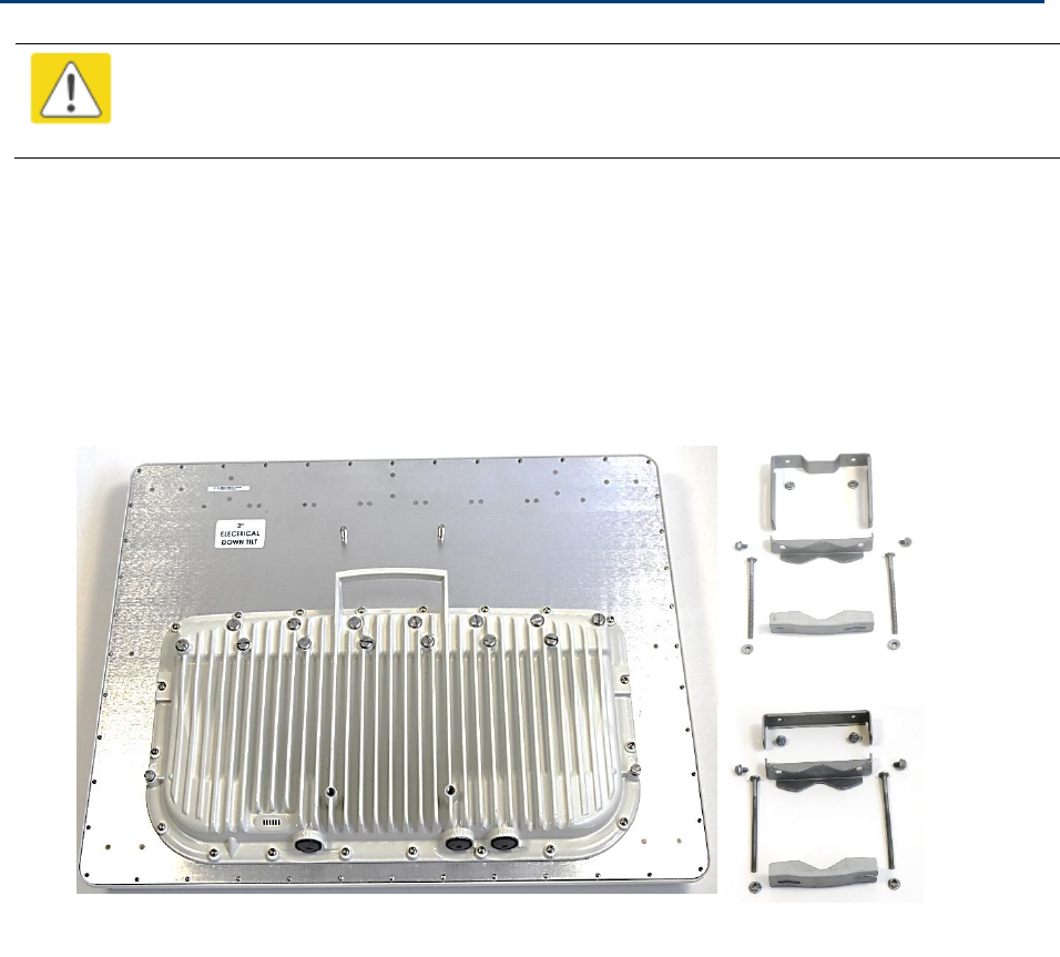
Attaching the PMP 450 AP to the antenna
To attach a PMP 450 Series AP to the antenna, perform the following steps.
Chapter 6: Installation
Installing external antennas to a connectorized ODU
Page 6-33
Note
Use shielded cable for all infrastructure connections associated with APs, SMs, and
CMMs. The environment that these modules operate in often has significant unknown
or varying RF energy. Operator experience consistently indicates that the additional
cost of shielded cables is more than compensated by predictable operation and
reduced costs for troubleshooting and support.
1
Attach the included bracket to the rear of
the AP using the (4) M5 x 7mm bolts
Figure 74 Attaching bracket to the rear of
the AP
2
Attach the AP to the antenna by sliding the bracket onto the bolts and tighten the (4)
serrated flange nuts using a 13 mm spanner wrench.
Figure 75 Lower bracket attached to AP antenna
Chapter 6: Installation
Installing external antennas to a connectorized ODU
Page 6-34
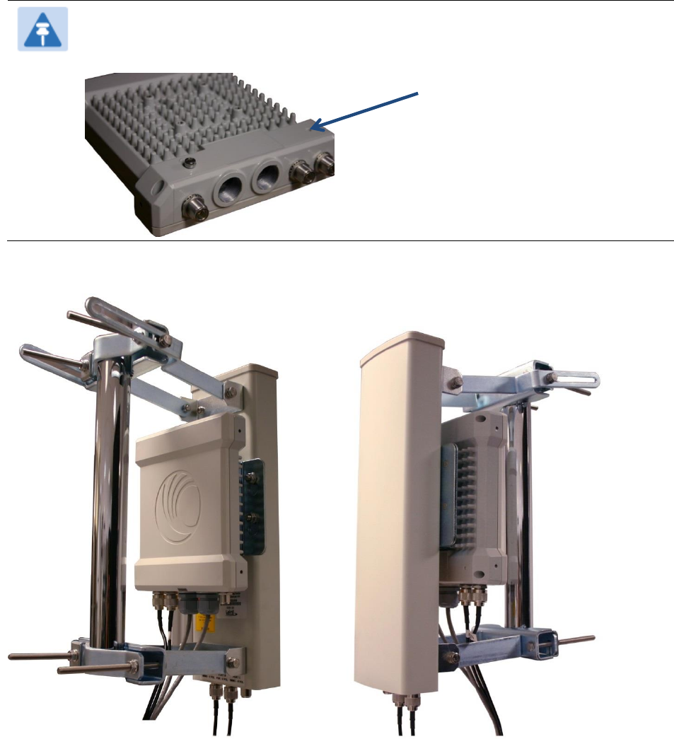
Note
If using a non-standard antenna, do not cover the equilibrium membrane vent located
on the back of the unit.
Figure 76 Mounted PMP 450 AP and antenna assembly, viewed from back and back
Equilibrium Membrane Vent
Chapter 6: Installation
Installing external antennas to a connectorized ODU
Page 6-35
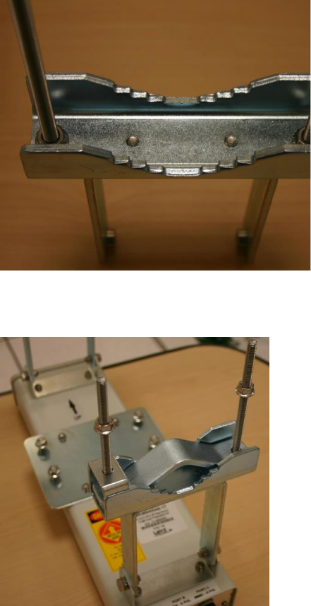
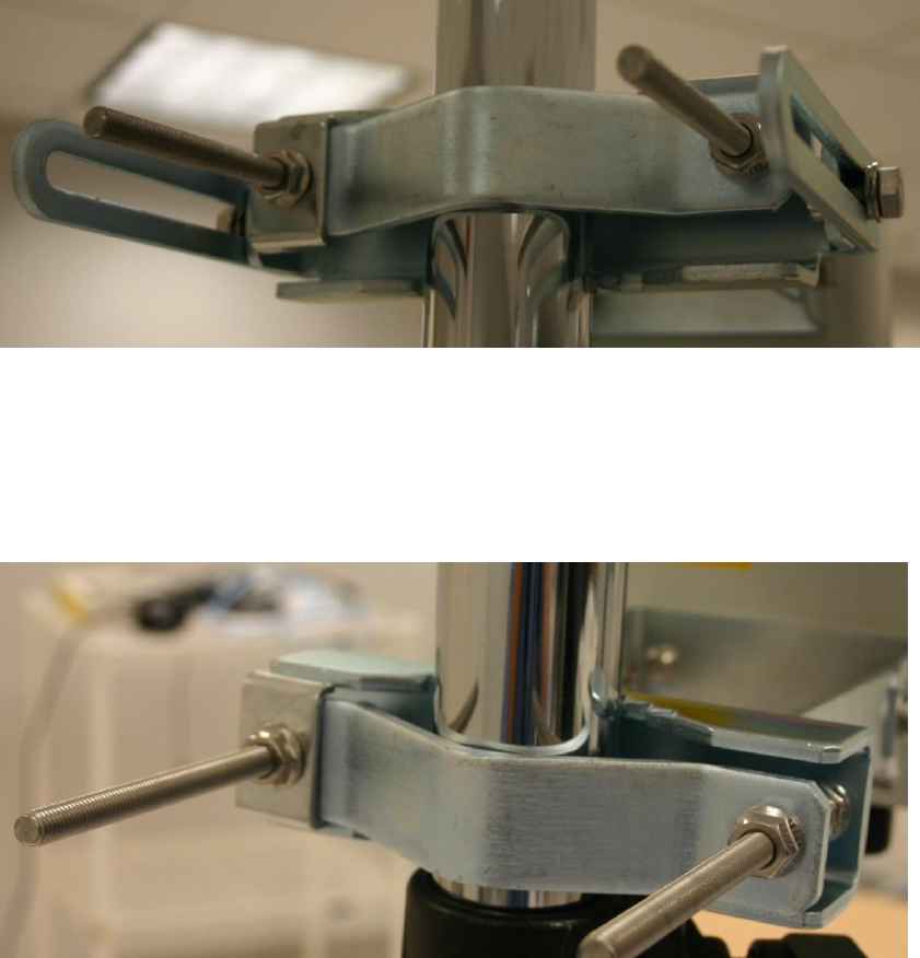
Attaching the PMP 450 platform AP and antenna to the mount
point
1
Attach the upper bracket of the antenna to the mount point by closing the rear strap around
the pole and tightening the (2) serrated flange nuts using a 13mm spanner wrench. These
must be tightened evenly on the pol to avoid jumping/stripping threads.
Figure 77 Attaching the AP antenna upper bracket to the pole
2
Attach the lower bracket of the antenna to the mount point by closing the rear strap around
the pole and tightening the (2) serrated flange nuts using a 13mm spanner wrench. These
must be tightened evenly on the pole to avoid jumping/stripping threads.
Figure 78 Attaching the AP antenna lower bracket to the pole
3
Use a local map, compass, and/or GPS device as needed to determine the direction that one
or more APs require to each cover the 90° sector.

Chapter 6: Installation
Installing external antennas to a connectorized ODU
Page 6-36
4
Choose the best mounting location for your particular application.
Note
Use the embedded spectrum analyzer or a commercial analyzer to evaluate
the frequencies present in various locations. OFDM APs need not be mounted
next to each other. They can be distributed throughout a given site. However,
the 90° offset must be maintained. If you want to collocate these APs with
PMP 100 Series APs of the 5.4-GHz frequency band range, plan to allow at
least 25 MHz of separation between their center channels.
5
Secure a ground strap to the ground lug on the back of the AP.
6
Secure the ground strap to the pole, tower, or other trusted ground.
7
The bracket of the standard antenna has provision for measured down tilt. The
recommended practice is to use one of the many radio analysis and mapping tools or on-
line tools to calculate down tilt based on antenna height above the service area.
The proper angle of tilt can be calculated as a factor of both the difference in elevation and
the distance that the link spans. Even in this case, a plumb line and a protractor can be
helpful to ensure the proper tilt. This tilt is typically minimal.
The number of degrees to offset (from vertical) the mounting hardware leg of the support
tube is equal to the angle of elevation from the lower module to the higher module (<B in
the example provided in Figure 43).

Chapter 6: Installation
Installing external antennas to a connectorized ODU
Page 6-37
Figure 79 Variables for calculating angle of elevation (and depression)
Where:
Is:
b
angle of elevation
B
vertical difference in elevation
A
horizontal distance between modules
To use metric units to find the angle of elevation, use the following formula:
Where:
Is:
B
expressed in meters
A
expressed in kilometers
To use English standard units to find the angle of elevation, use the following formula:
Where:
Is:
B
expressed in feet
A
expressed in miles
The angle of depression from the higher module is identical to the angle of elevation from
the lower module.
8
Connect the coax cables to the antenna and to the AP
9
Weatherproof the connector on the coax cables (see section Attaching and weatherproofing
an N type connector on page 6-68).
tan b = B
1000A
tan b = B
5280A
Chapter 6: Installation
Installing external antennas to a connectorized ODU
Page 6-38
PMP 450i Series 900 MHz AP
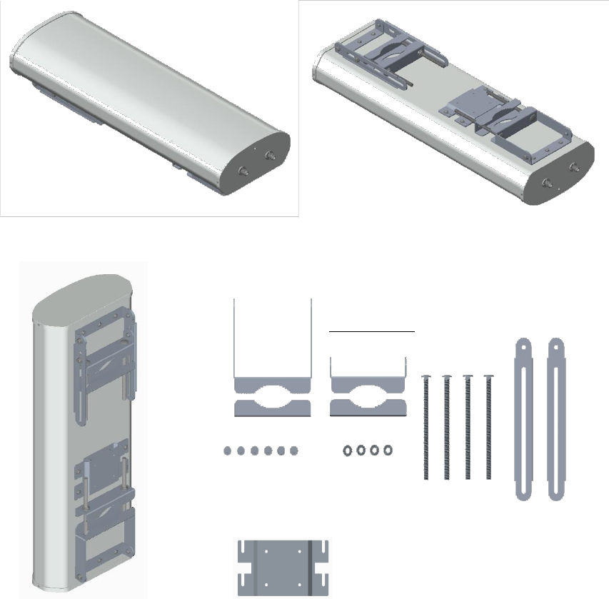
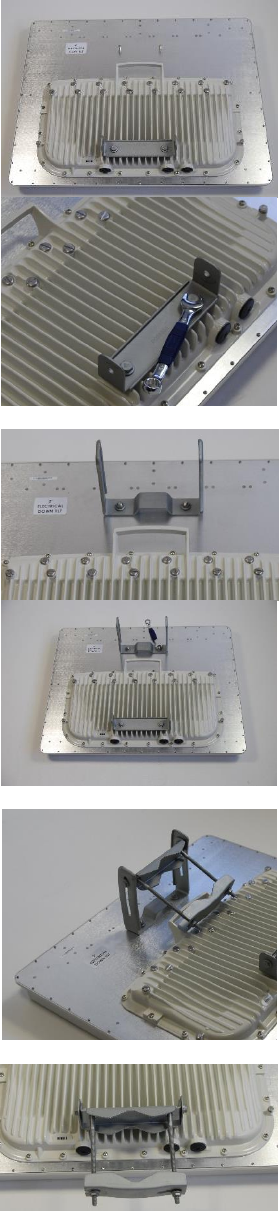
Mounting of PMP 450i 900 MHz AP
1
Inventory the parts to ensure that you have them all before you begin. The full set of parts
is shown in Figure 81.
Figure 80 PMP 450i 900 MHz AP antenna unbox view
Figure 81 PMP 450i 900 MHz AP antenna inventory
Upper bracket
Lower bracket
Adjustable arm
Nuts and bolts
Radio assembly plate
Chapter 6: Installation
Installing external antennas to a connectorized ODU
Page 6-39
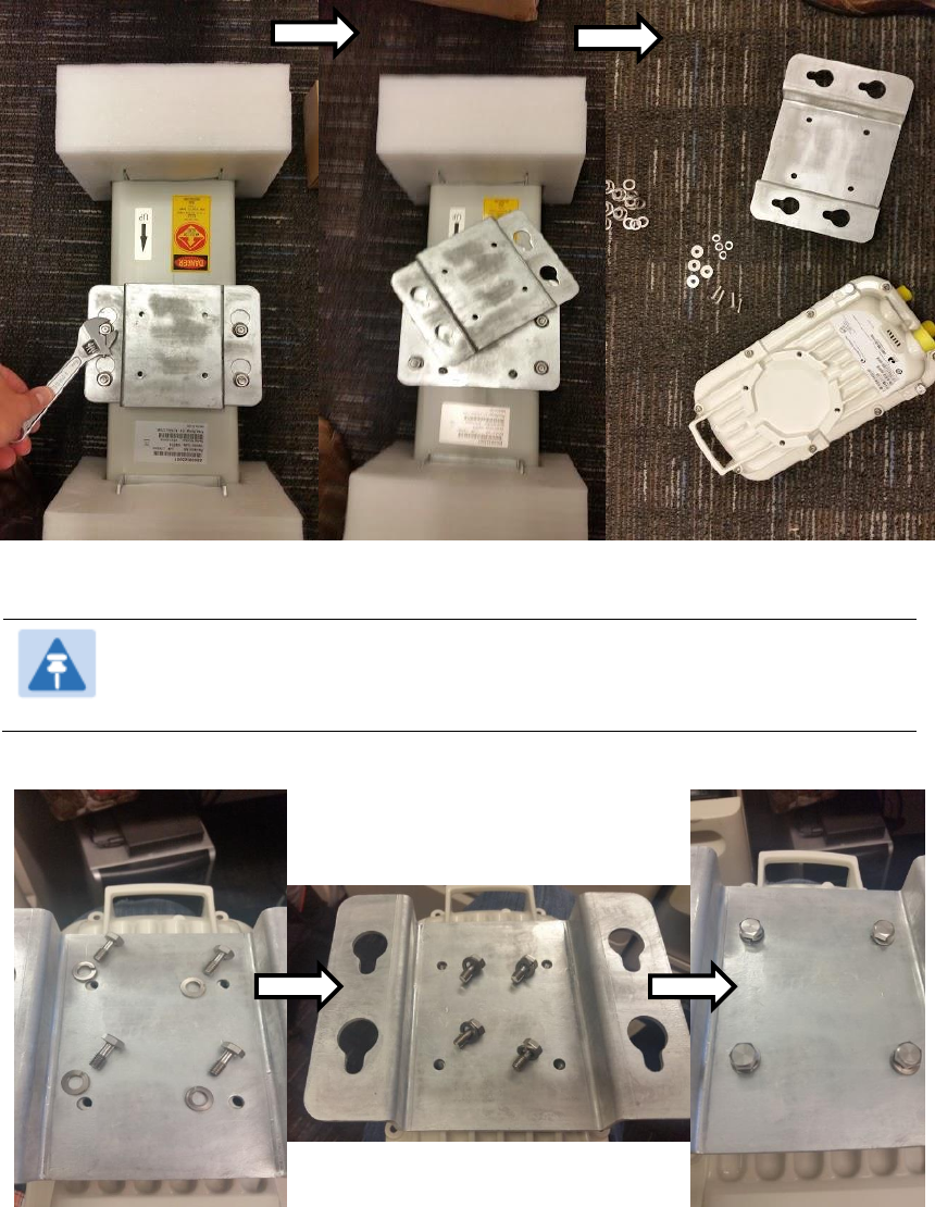
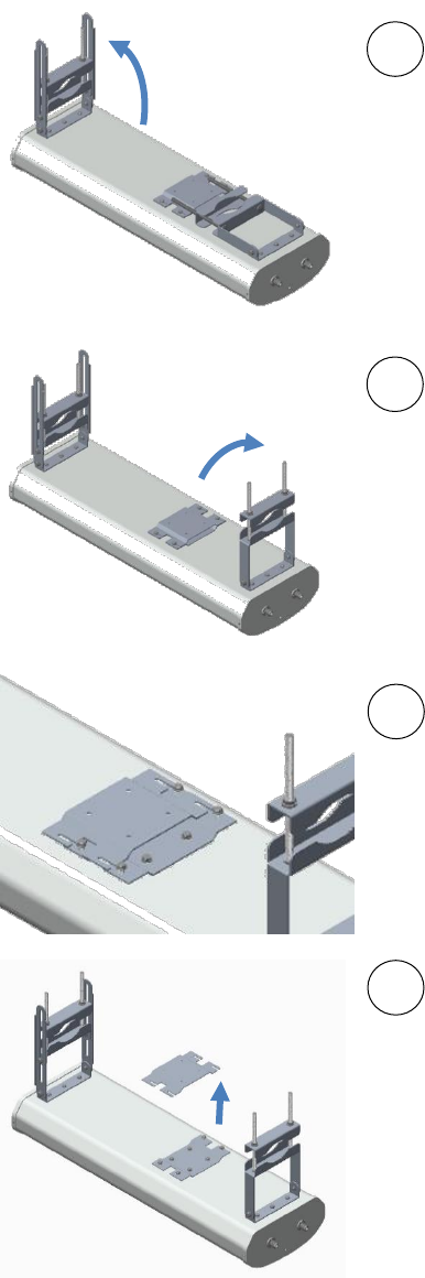
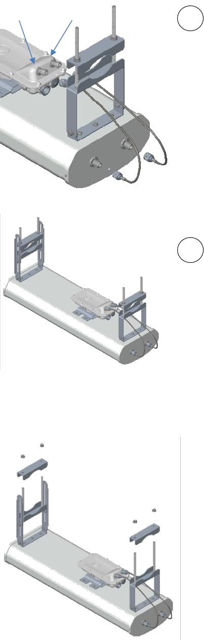
2
(1) Unfold the upper bracket assembly of the
antenna.
(2) Unfold the lower bracket assembly.
(3) Loose the radio assembly plate by
untightening M8 four bolds.
(4) Remove the radio assembly top plate by
sliding towards upper bracket assembly.
1
2
4
3
Chapter 6: Installation
Installing external antennas to a connectorized ODU
Page 6-40
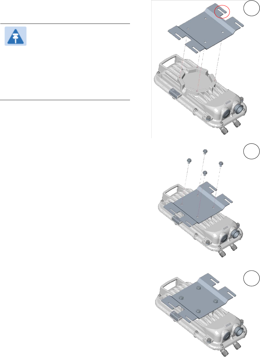
3
(1) Place the radio assembly plate on the
radio and align holes with radio enclosure.
Note
Ensure that the radio plate
notch opening and RF port of
radio in same direction. It is
also important to make sure
you attach the radio assembly
plate in the proper orientation
as shown in figure.
(2) Insert M8 bolts through plate into radio
enclosure
(3) Fix the plate by tightening four bolts
with a toreque setting on 2 ±0.5 Nm
1
2
3
Chapter 6: Installation
Installing external antennas to a connectorized ODU
Page 6-41
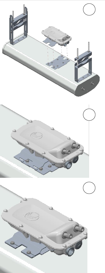
4
(1) Place the radio mounted plate on sector
antenna as show figure. Ensure that the
orinentation of RF port of antenna and radio
are in same direction
(2) Line up the radio assembly to four bolts
and slide towards lower bracket assembly
to lock.
(3) Tighten the radio assembly plate using
four M8 bolts to a toreque setting on 2 ±0.5
Nm
1
3
2
Chapter 6: Installation
Installing external antennas to a connectorized ODU
Page 6-42
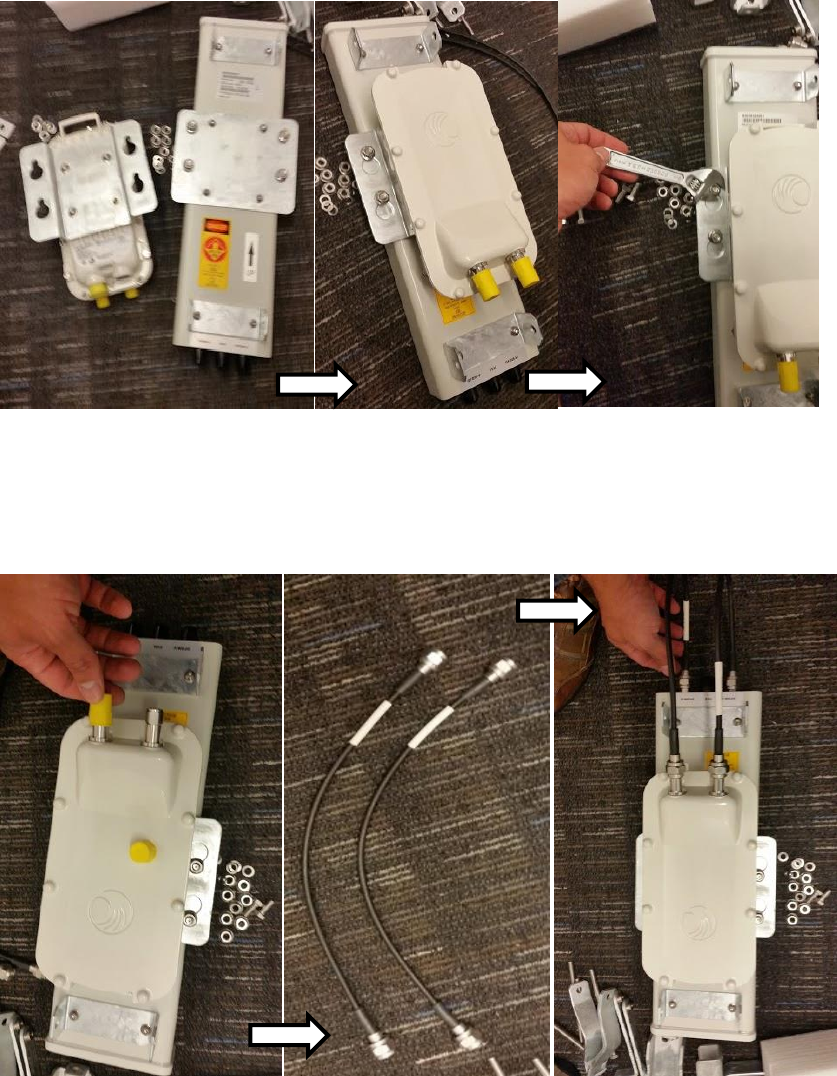
5
(1) Connect the port A of AP to vertical and
port B of AP to horizontal polarization
interfaces of the antenna with RF cable.
Ensure that the RF cables are passthrough
inside the lower bracket assembly
(2) Hand tighten the N type connectors and
the torque should not exceed more than 1
Nm
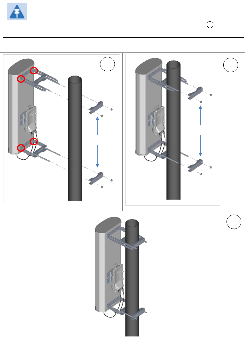
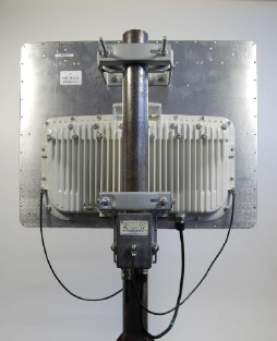
Mounting of PMP 450i 900 MHz AP antenna to the pole
The mounting procedure of PMP 450i 900 MHz AP and antenna to the pole is given below:
1
Remove the upper and lower rear bracket
strap from the sector antenna.
1
2
Port A
Port B
Chapter 6: Installation
Installing external antennas to a connectorized ODU
Page 6-43
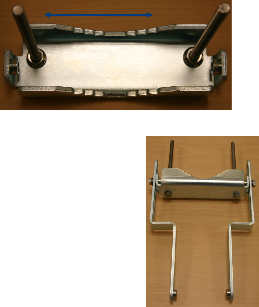
2
Attach the upper and lower bracket of the antenna to the mount point by closing the rear
strap around the pole.
Note
Before mounting the radio on pole, secure upper and lower bracket
assembly with a torque setting of 3 to 4 Nm as shown in Figure 1 . Also,
ensure that inner strap of upper bracket is set to zero degree marking.
Figure 82 Attaching radio mounting PMP 450i 900 MHz AP antenna to the pole
1
2
3
Rear strap
Rear strap
Inner strap
Chapter 6: Installation
Installing external antennas to a connectorized ODU
Page 6-44
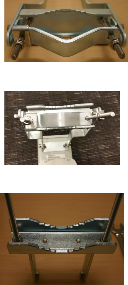
3
Tightening the four serrated flange M10
nuts on upper and lower rear strap using a
17 mm spanner wrench. These must be
tightened evenly on the pol to avoid
jumping/stripping threads
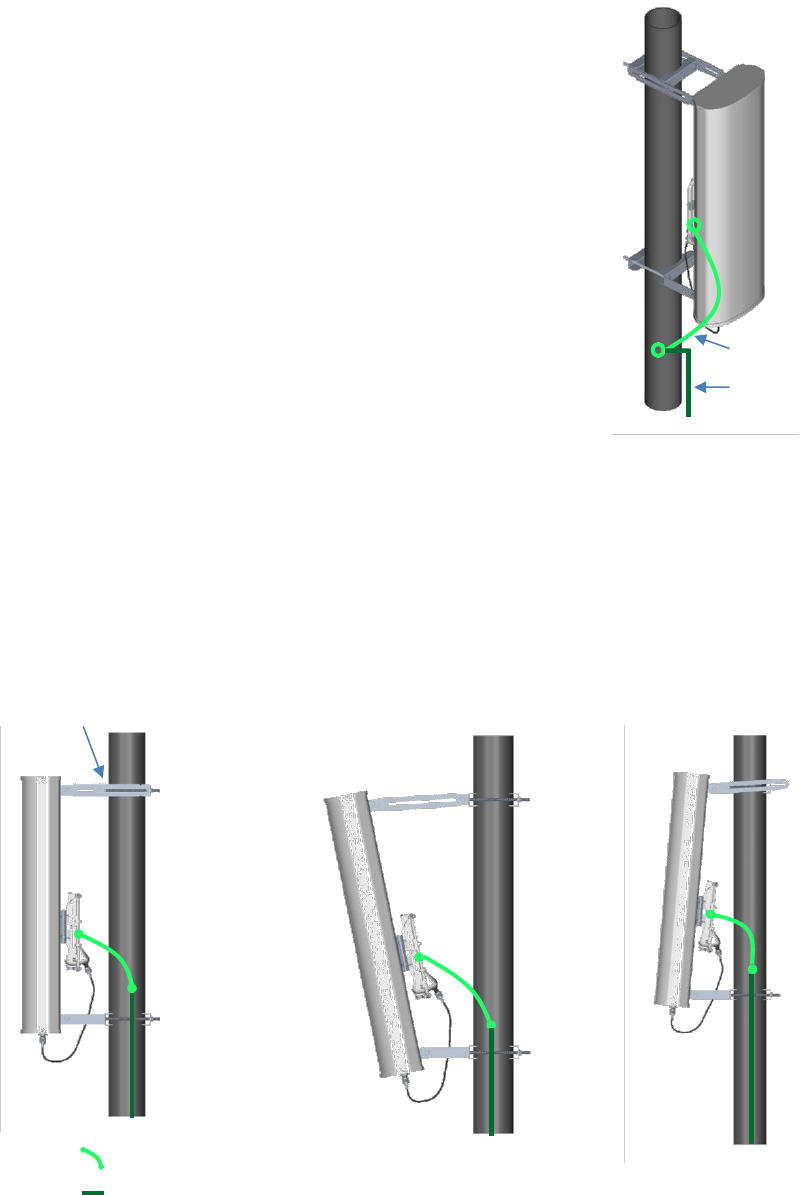
Sector antenna alignment
The 900 MHz sector antenna horizontal and vertical alignment procedure is shown in Figure 83.
The antenna can be aligned from +5 to -10 degree by adjusting inner strap of upper bracket
assembly.
Figure 83 900 MHz sector antenna alignment
Horizontal alignemtn
Vertical alignment
downlward tilt
Vertical alignment upward
tilt
Inner strap
Upper
bracket
assembly
ODU ground cable
Building ground
system
ODU ground cable
Building ground system
Chapter 6: Installation
Installing external antennas to a connectorized ODU
Page 6-45
PMP 450 Series 900 MHz SM
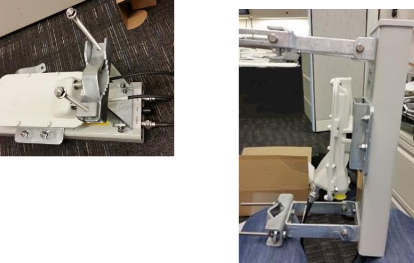
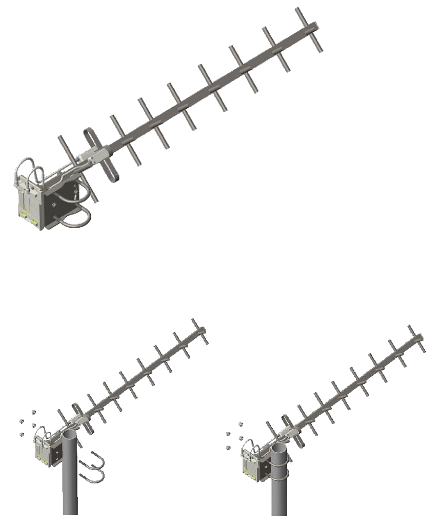
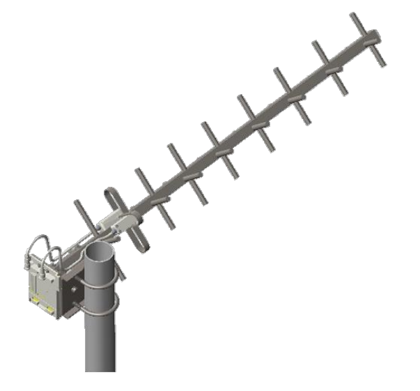
Attaching the SM 900 MHz directional antenna to the pole
1
Unbox the directional yagi antenna.
Figure 84 PMP 450i 900 MHz SM external directional antenna
2
Attach the directional atenna to the pole and insert the two U clamps into the mounting
bracket of the antenna
Figure 85 Attach the antenna to the pole
Chapter 6: Installation
Installing external antennas to a connectorized ODU
Page 6-46
3
Tighten all nuts to approximately 6 to 7 Nm or less to avoid deforming the pole.
Figure 86 Fixing the nuts
Chapter 6: Installation
Installing external antennas to a connectorized ODU
Page 6-47
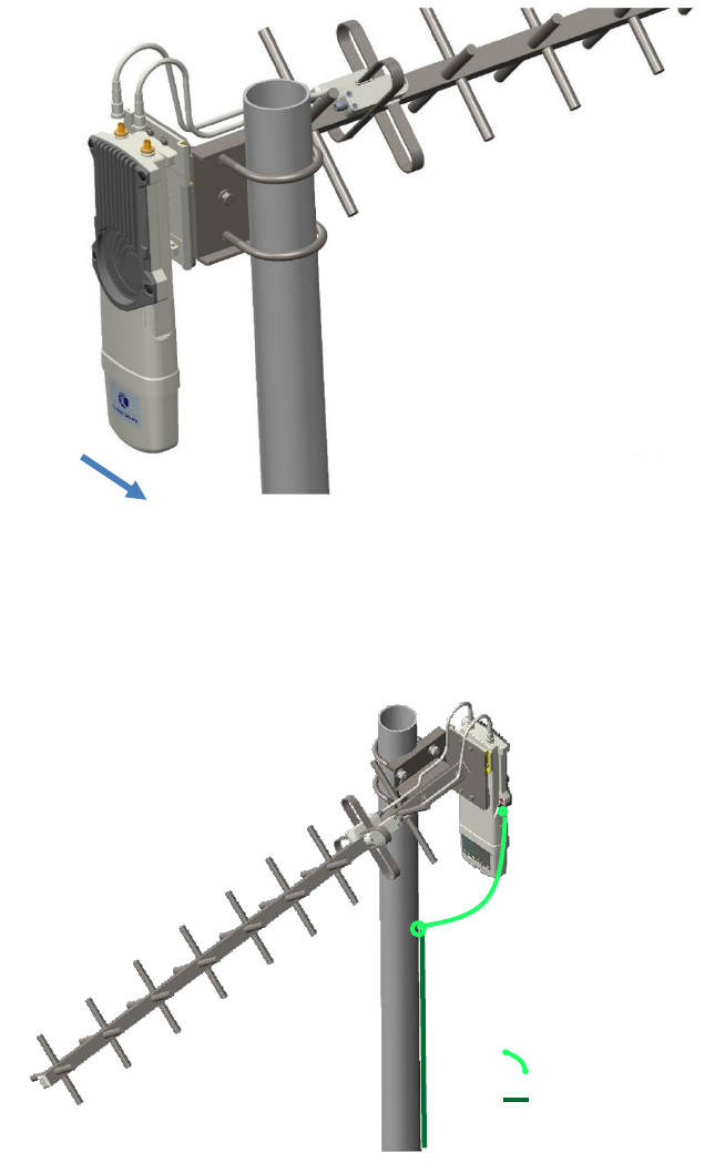
Radio mounting to the antenna
1
Align the radio to E bracket and slide towards right to lock on the antenna as shown in
figure.
Figure 87 Fixing the radio to the antenna
2
Connect the port A of SM to vertical and port B of SM to horizontal polarization interfaces
of the antenna with RF cable.
Figure 88 Connecting RF cable to the radio
Slide towards right to lock
ODU ground cable
Building ground system
Chapter 6: Installation
Installing external antennas to a connectorized ODU
Page 6-48
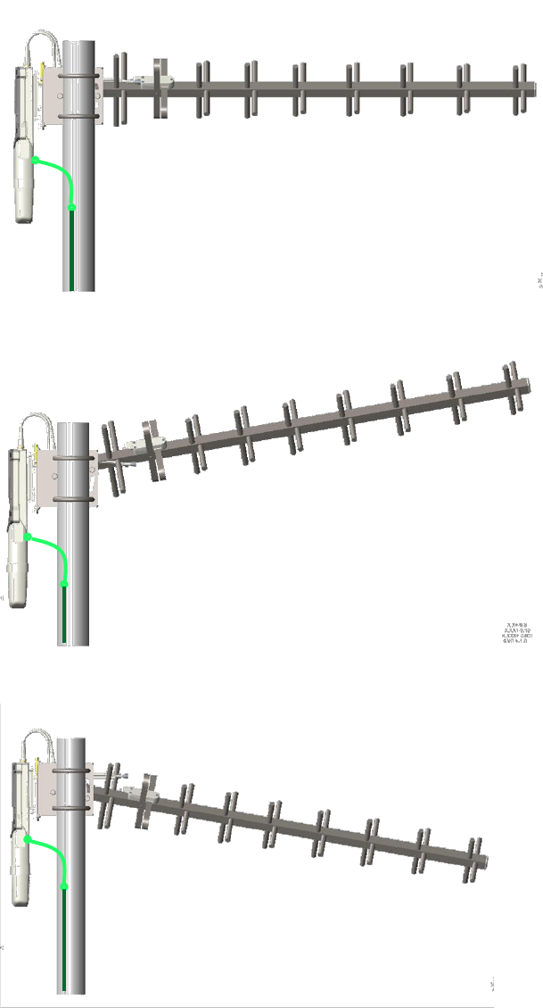
Directional Yagi antenna alignment
The directional Yagi antenna horizontal and vertical alignment procedure is shown below. The
Yagi antenna can be aligned for +15 to -15 degree.
Figure 89 Yagi antenn alignment - horizentaly
Figure 90 Yagi antenna alignment - upward tilt
Figure 91 Yagi antenna alignment - downward tilt
Chapter 6: Installation
Installing an integrated ODU
Page 6-49
Installing an integrated ODU
Caution
Do not reverse the bracket clamp, as this arrangement may lead to failure of the
assembly. Do not over-tighten the bolts as this may lead to failure of the assembly.
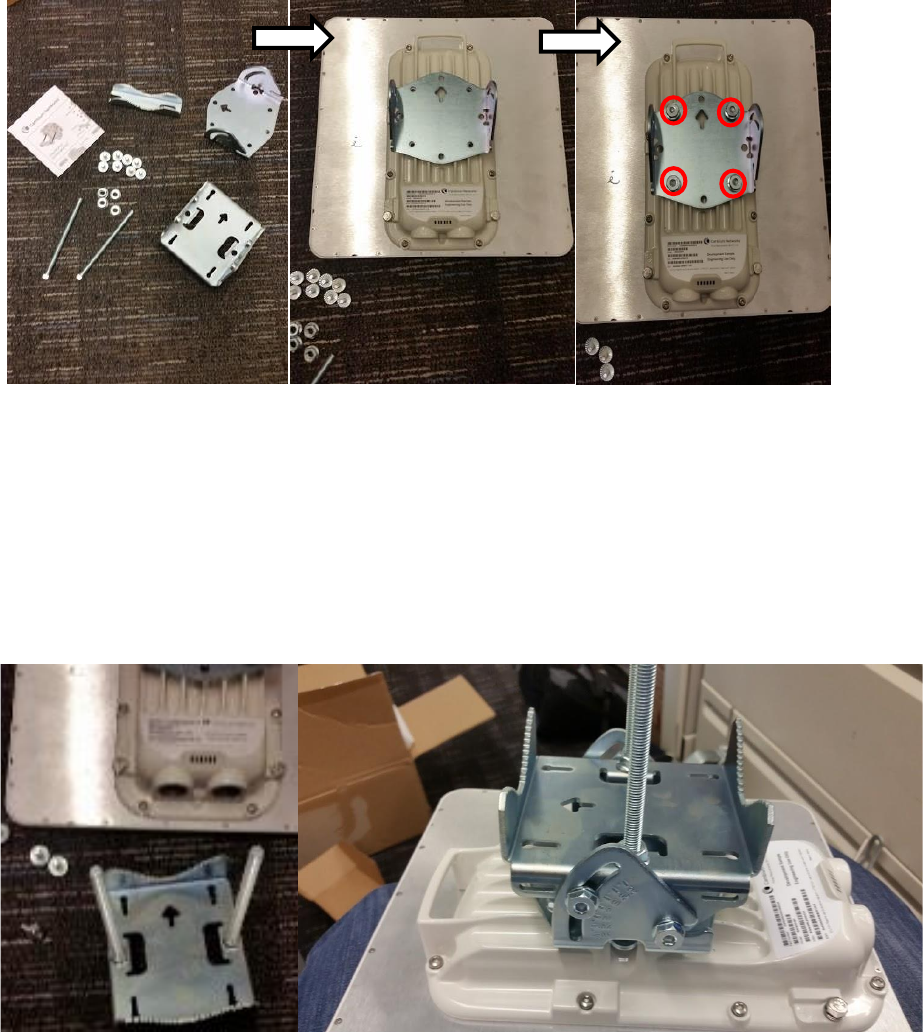
PMP 450m Series – AP
To mount and connect an integrated ODU, proceed as follows:
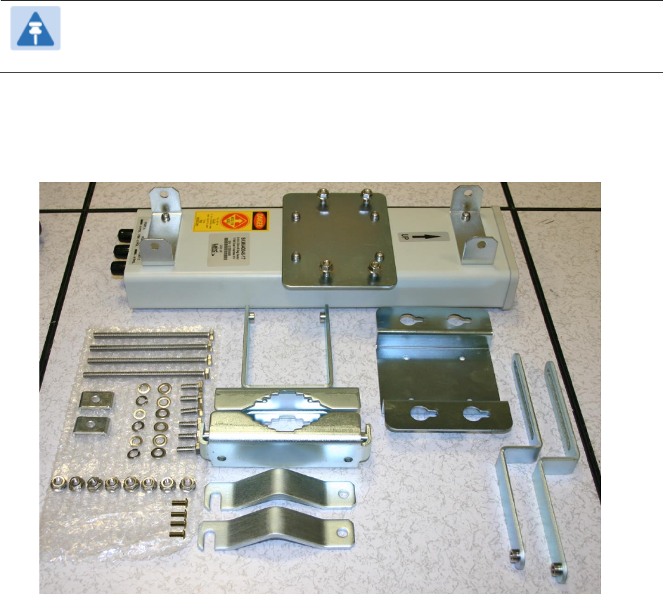
1
Inventory the parts to ensure that you have them all before you begin. The full set of parts
is shown in Figure 92.
Figure 92 PMP 450m Series - AP unbox view
PMP 450m AP
Bottom bracket
Top bracket
Chapter 6: Installation
Installing an integrated ODU
Page 6-50
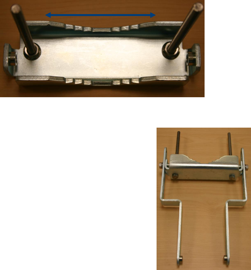
2
Attach the bottom bracket to ODU using (2) hex bolts
and tighten the bolts.
3
Insert the top bracket to projected two bolts of ODU and
and tighten the top bracket using two nuts.
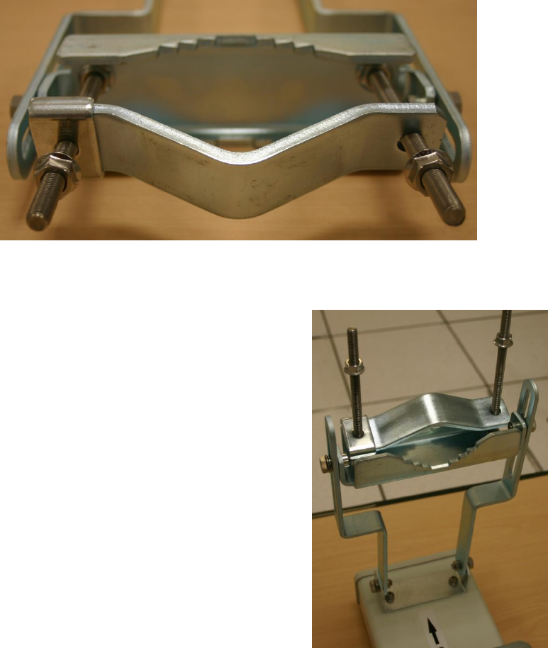
4
Fix the front and rear strap assembly to the upper
bracket using two bolts. Do not tighten the nuts now.
5
Fix the front and rear strap assembly to the bottom
bracket using two bolts. Do not tighten the nuts now.
Chapter 6: Installation
Installing an integrated ODU
Page 6-52
PMP/PTP 450i Series – AP/SM/BH
To mount and connect an integrated ODU, proceed as follows:
1
Fix the mounting plate to the back of the ODU using the four M6 bolts, and spring and plain
washers provided. Tighten the bolts to a torque setting of 5.0 Nm (3.7 lb ft).
Figure 93 Fixing the mounting plate to the back of the ODU
2
Attach the bracket body to the mounting plate using the M8 bolt, spring and plain washers.
3
Hoist the ODU to the mounting position.
4
Attach the bracket body to the pole using the bracket clamp, M8 bolts, and spring and plain
washers.
5
If the ODU is mounted outdoors, weatherproof the N type connectors (when antenna alignment
is complete) using PVC tape and self-amalgamating rubber tape.
Figure 94 Attaching the bracket body
Chapter 6: Installation
Connecting Cat5e Ethernet cable
Page 6-53
Connecting Cat5e Ethernet cable
Connecting an RJ45 and gland to a unit
Perform this task to connect the Ethernet cable to an AP.
To connect the Ethernet cable with a gland to an AP unit, proceed as follows:
1
Insert the RJ45 cable through the gland components
2
Insert the RJ45 plug into the socket in the unit, making sure that the locking tab snaps
home.
3
Support the drop cable and gently hand screw the gland body into the unit until the
bushing seal is flush to the unit body.
Note
Do not fit the back shell prior to securing the gland body.
4
Once the gland is fully hand screwed into the unit, tighten it one full rotation only with a 1
1/8 inch spanner wrench.
5
When the gland body has been fitted, tighten the gland back shell.
Caution
Do not over-tighten the gland back shell, as the internal seal and structure or RJ45 port
may be damaged.
Chapter 6: Installation
Connecting Cat5e Ethernet cable
Page 6-54
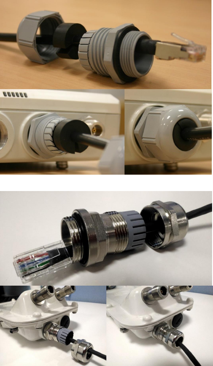
Figure 95 Ethernet cable gland for PMP/PTP 450 Series
Figure 96 Ethernet cable gland for PMP/PTP 450i Series
Chapter 6: Installation
Connecting Cat5e Ethernet cable
Page 6-55
Figure 97 Ethernet cable gland for PMP 450m Series
Disconnecting an RJ45 and gland from a unit
Perform this task to disconnect the Ethernet cable and watertight gland from ODU.
To disconnect the Ethernet cable and gland from a unit, proceed as follows:
1
Hold Ethernet cable and remove the gland back shell
2
Use a small flathead screwdriver (0.2”/5mm wide or greater) to gently release the black
plastic watertight bushing from the compression fins, being careful not to damage the
bushing.
3
Unscrew the gland body from the AP, making sure that the Ethernet cable is not rotating
while disengaging the gland body from the AP housing
4
Use a small screwdriver to depress the RJ45 locking clip
5
Unplug the RJ45 cable
6
Remove the gland from the cable, if necessary

Chapter 6: Installation
Installing ODU
Page 6-56
Installing ODU
Installing an PMP 450 platform AP
To install a PMP 450 platform Series AP, perform the following steps.
Procedure 5 Installing an AP
1
Begin with the AP in the powered-down state.
2
Choose the best mounting location for your particular application. Modules need not
be mounted next to each other. They can be distributed throughout a given site.
However, the 60° offset must be maintained. Mounting can be done with supplied
clamps.
See Installing external antennas to a connectorized ODU on page 6-21 for connecting
external antenna to PMP 450i Series, PMP 450 Series, PMP 450i Series 900 MHz AP
and PMP 450 Series 900 MHz SM
See Installing an integrated ODU on page 6-49
3
Align the AP as follows:
a. Move the module to where the link will be unobstructed by the radio horizon and
no objects penetrate the Fresnel zone.
b. Use a local map, compass, and/or GPS device as needed to determine the
direction that one or more APs require to each cover the intended 60° sector.
c. Apply the appropriate degree of downward tilt.
d. Ensure that the nearest and furthest SMs that must register to this AP are within
the beam coverage area.
4
Adjust the azimuth to achieve visual alignment, lock the AP in the proper direction
and downward tilt.
5
Attach the cables to the AP (See Powering the AP/SM/BH for test configuration on
Page 5-15)
6
W
aterproof the cables (See section Attaching and weatherproofing an N type connector
on page 6-68).

Chapter 6: Installation
Installing ODU
Page 6-57
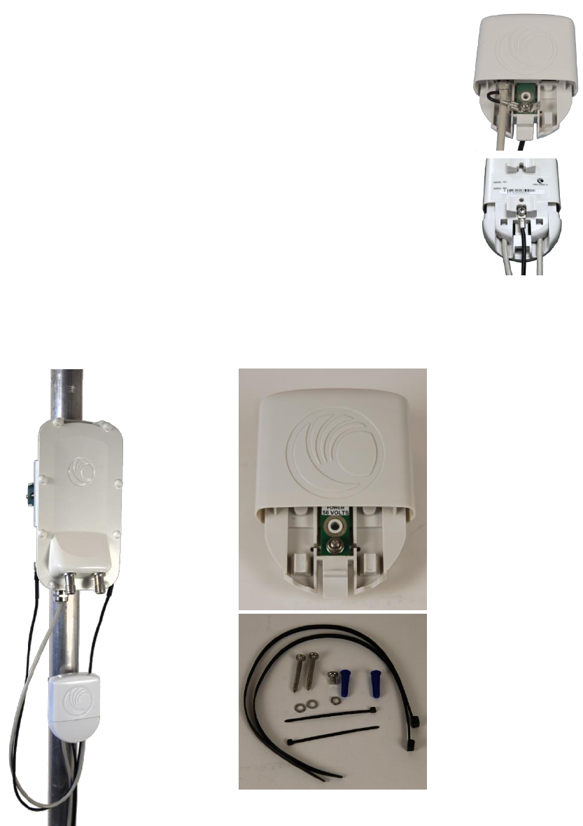
Installing a PMP 450 platform SM
Installing a PMP 450 platform Series SM consists of two procedures:
Physically installing the SM on a residence or other location and performing a coarse
alignment using the alignment tool or alignment tone.
Verifying the AP to SM link and finalizing alignment using review of power level, link tests, and
review of registration and session counts.
Procedure 6 Installing an SM
1
Choose the best mounting location for the SM based on section ODU and external
antenna location on page 3-10.
2
Use stainless steel hose clamps or equivalent fasteners to lock the SM into position.
See Installing external antennas to a connectorized ODU on page 6-21 for
connecting external antenna
See Installing an integrated ODU on page 6-49
3
Remove the base cover of the SM.
4
Terminate the UV outside grade Category 5 Ethernet cable with an RJ-45 connector,
and connect the cable to the SM.
5
Wrap a drip loop in the cable.
6
For Connectorized Models, Install the external antenna according to the
manufacturer’s instructions.
7
For Connectorized Models, connect the SM’s N-type antenna connectors to the
external antenna, ensuring that the polarity matches between the SM cable labeling
and the antenna port labels.
Connectorized SM Antenna Cable Label
Antenna Connection
A
Vertical
B
Horizontal
8
For Connectorized Models, weatherproof the N-type antenna connectors following
section Attaching and weatherproofing an N type connector on page 6-68.
9
Wrap an AWG 10 (or 6mm2) copper wire around the Ground post of the SM
10
Securely connect the copper wire to the grounding system (Protective Earth)
according to applicable regulations.
11
Install an surge suppressor as describe in section Mount the Surge Suppressor on
page 6-9
12
Connect the power supply to a power source.
13
Connect the Ethernet output from the power supply to the Ethernet port of
your laptop.
Chapter 6: Installation
Installing ODU
Page 6-58
14
Launch your web browser. In the URL address bar, enter 169.254.1.1. then press
Enter.
15
If the browser in laptop fails to access the interface of the SM, follow the procedure
Radio recovery mode on page 1-22
16
Log in as admin on the ODU. Configure a password for the admin account and log
off.
17
Log back into the SM as admin or root, using the password that you configured.
18
For coarse alignment of the SM, use the Alignment Tool located at Tools, Alignment
Tool.
Optionally, connect a headset to the AUX/SYNC port the SM and listen to the
alignment tone, which indicates greater SM receive signal power by pitch. By
adjusting the SM’s position until the highest frequency pitch is obtained operators
and installers can be confident that the SM is properly positioned. For information
on device GUI tools available for alignment, see sections Using the Alignment Tool,
Using the Link Capacity Test tool, and Using AP Evaluation tool below.
19
When the highest power achieved, lock the SM mounting bracket in place.
20
Log off of the SM web interface.
21
Disconnect the Ethernet cable from your laptop.
22
Replace the base cover of the SM.
23
Connect the Ethernet cable to the computer that the subscriber will be using.
Installing a PTP 450 platform BHM
To install a PTP 450 platform Series BHM, perform the following steps.
Procedure 7 Installing a BHM
1
Access the General tab of the Configuration page in the BHM
2
Choose the best mounting location for your particular application.
3
Align the BHM as follows:
a. Move the module to where the link will be unobstructed by the radio horizon
and no objects penetrate the Fresnel zone.
b. Use a local map, compass, and/or GPS device as needed to determine the
direction to the BHS.
c. Apply the appropriate degree of downward or upward tilt.
d. Ensure that the BHS is within the beam coverage area.
Chapter 6: Installation
Installing ODU
Page 6-59
4
Using stainless steel hose clamps or equivalent fasteners, lock the BHM into
position.
See Installing external antennas to a connectorized ODU on page 6-21 for
connecting external antenna
5
If this BHM will not be connected to a CMM, optionally connect a utility cable to a
GPS timing source and then to the SYNC port of the BHM.
6
Either connect the BHM’s Aux to the CMM or connect the DC power converter to the
BHM and then to an AC power source.
RESULT: When power is applied to a module or the unit is reset on the web-based
interface, the module requires approximately 25 seconds to boot. During this
interval, self-tests and other diagnostics are being performed.
7
Access Configuration > General page of the BHM for Synchronization configuration.
8
If a CMM4 is connected, set the Sync Input parameter to the AutoSync or Autosync
+ Free Run selection.
Installing a PTP 450 platform BHS
To install a PTP 450 platform Series BHS, perform the following steps.
Procedure 8 Installing a BHS
1
Choose the best mounting location for the BHS.
2
Terminate the UV outside grade Category 5 Ethernet cable with an RJ-45 connector,
and connect the cable to the BHS. (See Powering the AP/SM/BH for test
configuration on Page 5-15)
3
Use stainless steel hose clamps or equivalent fasteners to lock the BHS into
position.
4
Install an surge suppressor as describe in section Mount the Surge Suppressor on
page 6-9
5
For coarse alignment of the BHS, use the Audible Alignment Tone feature as
follows:
a. At the BHS, connect the RJ-45 connector of the Alignment Tool Headset to the
Aux port via alignment tone adapter as shown in Figure 158 on page 8-20.
b. Listen to the alignment tone for pitch, which indicates greater signal power
(RSSI/dBm) by higher pitch.
Adjust the module slightly until you hear the highest pitch and highest volume
6
When you have achieved the best signal (highest pitch, loudest volume), lock the
BHS in place with the mounting hardware
Chapter 6: Installation
Installing ODU
Page 6-60
Configuring the Link
See Configuring remote access on page 7-255.
Monitoring the Link
See Monitoring the Link on page 7-256.
Chapter 6: Installation
Installing the AC Power Injector
Page 6-61
Installing the AC Power Injector
Caution
As the PSU is not waterproof, locate it away from sources of moisture, either in the
equipment building or in a ventilated moisture-proof enclosure. Do not locate the PSU
in a position where it may exceed its temperature rating.
Caution
Do not plug any device other than a PMP/PTP 450i ODU into the ODU port of the PSU.
Other devices may be damaged due to the non-standard techniques employed to
inject DC power into the Ethernet connection between the PSU and the ODU.
Do not plug any device other than a Cambium PMP/PTP 450 platform PSU into the
PSU port of the ODU. Plugging any other device into the PSU port of the ODU may
damage the ODU and device.
Installing the AC Power Injector
Follow this procedure to install the AC Power Injector:
1
Form a drip loop on the PSU end of the LPU to PSU drop cable. The drip loop ensures that
any moisture that runs down the cable cannot enter the PSU.
2
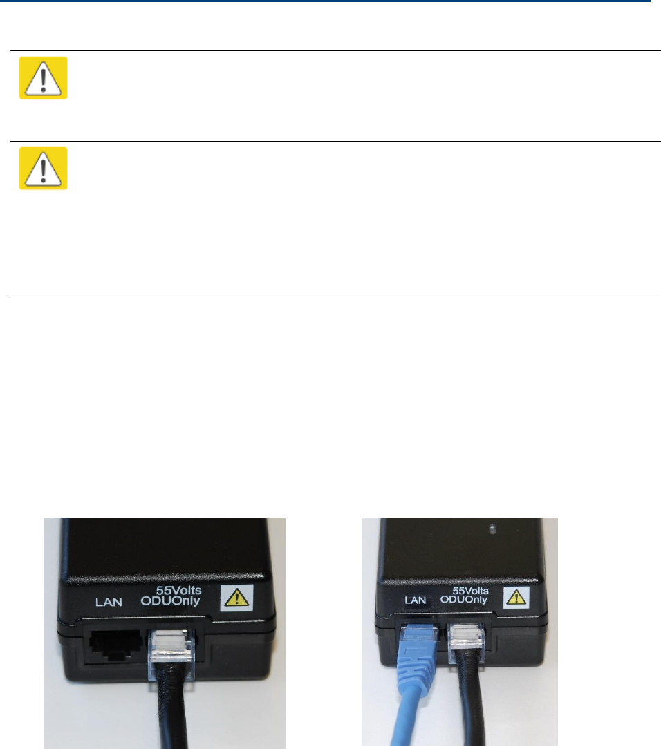
(a) Place the AC Power Injector on a horizontal surface. Plug the LPU to PSU drop cable into
the PSU port labeled ODU. (b) When the system is ready for network connection, connect the
network Cat5e cable to the LAN port of the PSU:
(a)
(b)

Chapter 6: Installation
Installing CMM4
Page 6-62
Installing CMM4
Note
For instructions on CMM3 (CMMmicro) or CMM4 installation, including the outdoor
temperature range in which it is acceptable to install the unit, tools required,
mounting and cabling instructions, and connectivity verification, please see the
PMP Synchronization Solutions User Guide located on the Cambium website.
The Cluster Management Module 4 (CMM4) provides power, sync, and network connectivity for up
to eight APs, backhauls, and Ethernet terrestrial feeds in a variety of configurations. The CMM4
provides
Sync over Power over Ethernet and integrated surge suppression on the controller board for
up to 8 APs or BHs. Both a custom 30 VDC power scheme and a custom 56 VDC power scheme
are available. Neither is the same as the later IEEE Standard 802.3af, and neither is compatible
with it.
Managed switching using a hardened EtherWAN switch (1090CKHH models). The CMM4 ships
with a 14-port EtherWAN switch and is also available without a switch. The CMM4 originally
shipped with a 9-port EtherWAN switch.
Surge suppression on the controller board for the incoming 30V DC and 56V DC power lines
and GPS coax cable.
Auto-negotiation on the Ethernet ports. Ports will auto-negotiate to match inputs that are either
100Base-T or 10Base-T, and either full duplex or half duplex, when the connected device is set
to auto-negotiate. Alternatively, these parameters are settable.
An always-on NTP (Network Time Protocol) server that can provide date and time to any radio
that can reach the CMM’s management IP address.
CNUT can be used to upgrade the CMM-4 software.
PMP/PTP 450 platform can use the CMM4’s EtherWan switch for their network connectivity.
Note
The 56V of a CMM4 needs to go through the adapter cable (part number
N000045L001A) as shown in Figure 24 on page 2-36.
The CMM4 56V power adapter cable can be prepared by swapping pins 5 and 7.
See CMM4 56V power adapter cable pinout on page 2-36 for power adapter cable
pinout.
Chapter 6: Installation
Installing CMM4
Page 6-63
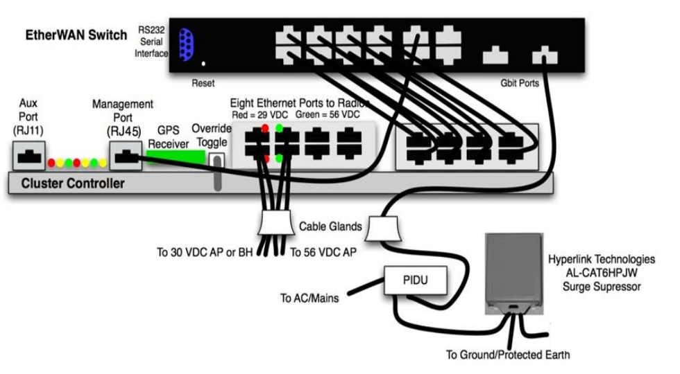
Figure 98 CMM4 cabled to support PMP/PTP 450 platform
To PMP/PTP 450
platform Radio
Chapter 6: Installation
Supplemental installation information
Page 6-64
Supplemental installation information
This section contains detailed installation procedures that are not included in the above topics,
such as how to strip cables, create grounding points and weatherproof connectors.
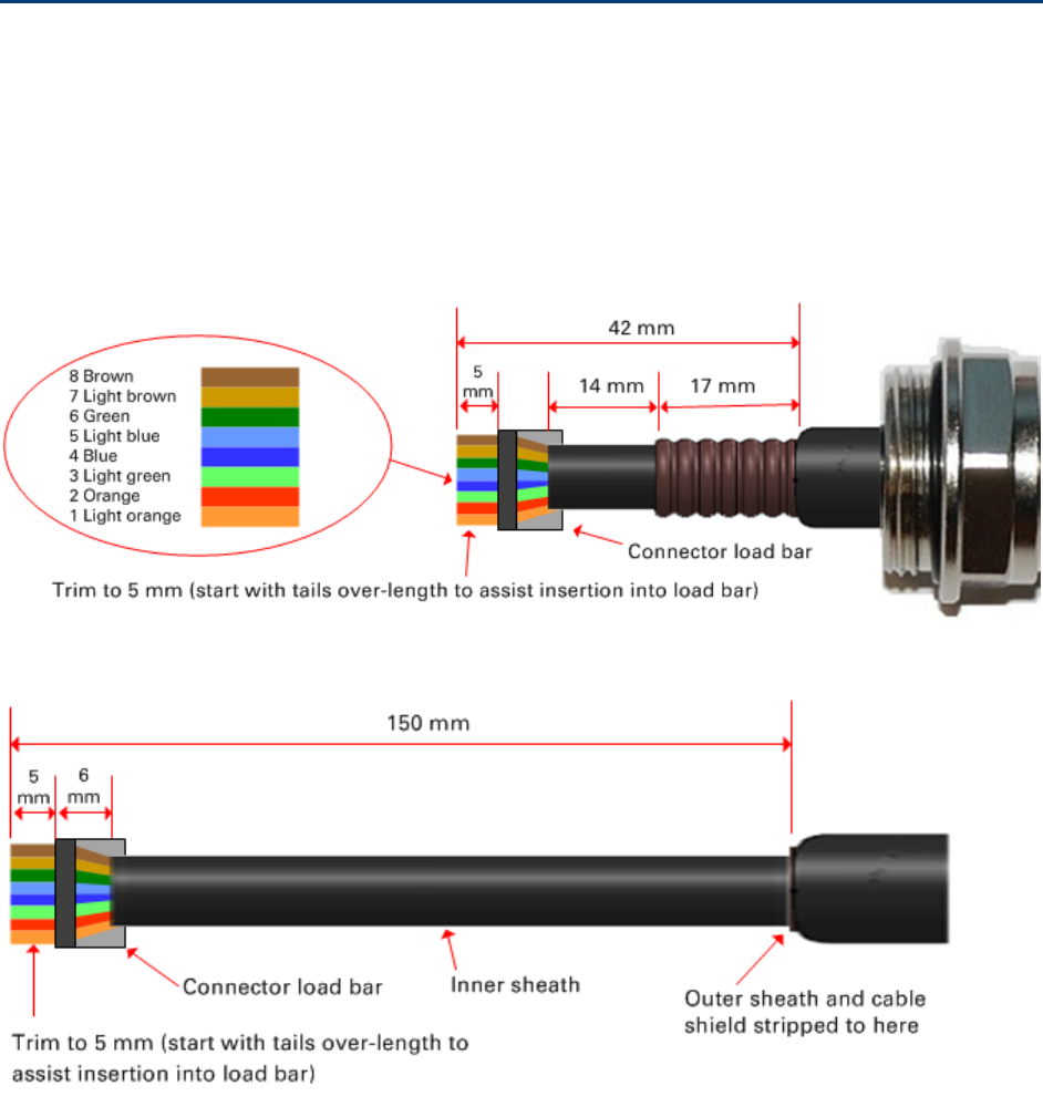
Stripping drop cable
When preparing drop cable for connection to the PMP/PTP 450 platform ODU or LPU, use the
following measurements:
When preparing drop cable for connection to the PMP/PTP 450 platform PSU (without a cable
gland), use the following measurements:
Chapter 6: Installation
Supplemental installation information
Page 6-65
Creating a drop cable grounding point
Use this procedure to connect the screen of the main drop cable to the metal of the supporting
structure using the cable grounding kit (Cambium part number 01010419001).
To identify suitable grounding points, refer to Drop cable grounding points on page 3-14.
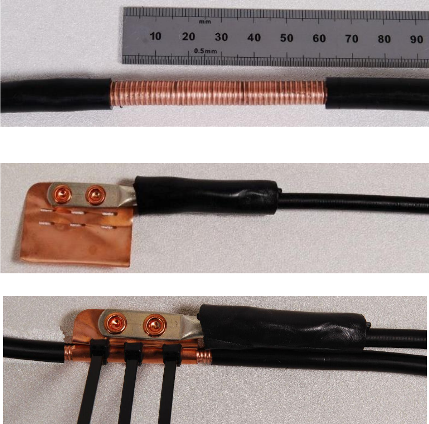
1
Remove 60 mm (2.5 inches) of the drop cable outer sheath.
2
Cut 38mm (1.5 inches) of rubber tape (self-amalgamating) and fit to the ground cable lug.
Wrap the tape completely around the lug and cable.
3
Fold the ground wire strap around the drop cable screen and fit cable ties.
Chapter 6: Installation
Supplemental installation information
Page 6-66
4
Tighten the cable ties with pliers. Cut the surplus from the cable ties.
5
Cut a 38mm (1.5 inches) section of self-amalgamating tape and wrap it completely around the
joint between the drop and ground cables.
6
Use the remainder of the self-amalgamating tape to wrap the complete assembly. Press the
tape edges together so that there are no gaps.
Chapter 6: Installation
Supplemental installation information
Page 6-67
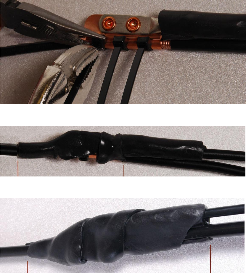
7
Wrap a layer of PVC tape from bottom to top, starting from 25 mm (1 inch) below and
finishing 25 mm (1 inch) above the edge of the self-amalgamating tape, overlapping at half
width.
8
Repeat with a further four layers of PVC tape, always overlapping at half width. Wrap the
layers in alternate directions (top to bottom, then bottom to top). The edges of each layer
should be 25mm (1 inch) above (A) and 25 mm (1 inch) below (B) the previous layer.
9
Prepare the metal grounding point of the supporting structure to provide a good electrical
contact with the grounding cable clamp. Remove paint, grease or dirt, if present. Apply anti-
oxidant compound liberally between the two metals.
10
Clamp the bottom lug of the grounding cable to the supporting structure using site approved
methods. Use a two-hole lug secured with fasteners in both holes. This provides better
protection than a single-hole lug.
Chapter 6: Installation
Supplemental installation information
Page 6-68
Attaching and weatherproofing an N type connector
The following procedure should be used to weatherproof the N type connectors fitted to the
connectorized ODU (AP/SM/BH) and antenna. This procedure must be followed to ensure that
there is no moisture ingress at the radio ports. Failure to properly seal N-type antenna connectors
can result in poor link performance or complete loss of radio communication.
Note
Cambium recommends to assemble the antenna, attach the ODU and cabling, and to
seal the RF connections before installing the unit at the deployment site.
Note
N type connectors should be tightened using a torque wrench, set to 15 lb in or 1.7
Nm. If a torque wrench is not available, N type connectors may be finger tightened.
Use this procedure to weatherproof the N type connectors fitted to the connectorized ODU and
external antenna (if recommended by the antenna manufacturer).
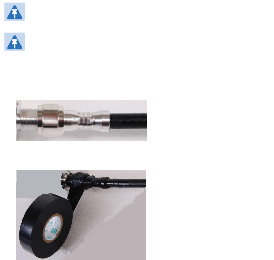
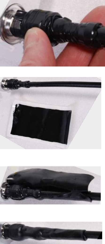
1
Ensure the connection is tight. A torque wrench should be used if available:
2
Wrap the connection with a layer of 19 mm (0.75 inch) PVC tape, starting 25 mm (1 inch)
below the connector body. Overlap the tape to half-width and extend the wrapping to the
body of the LPU. Avoid making creases or wrinkles:
Chapter 6: Installation
Supplemental installation information
Page 6-69
3
Smooth the tape edges:
4
Cut a 125mm (5 inches) length of rubber tape (self-amalgamating):
5
Expand the width of the tape by stretching it so that it will wrap completely around the
connector and cable:
6
Press the tape edges together so that there are no gaps. The tape should extend 25 mm
(1 inch) beyond the PVC tape:
Chapter 6: Installation
Supplemental installation information
Page 6-70
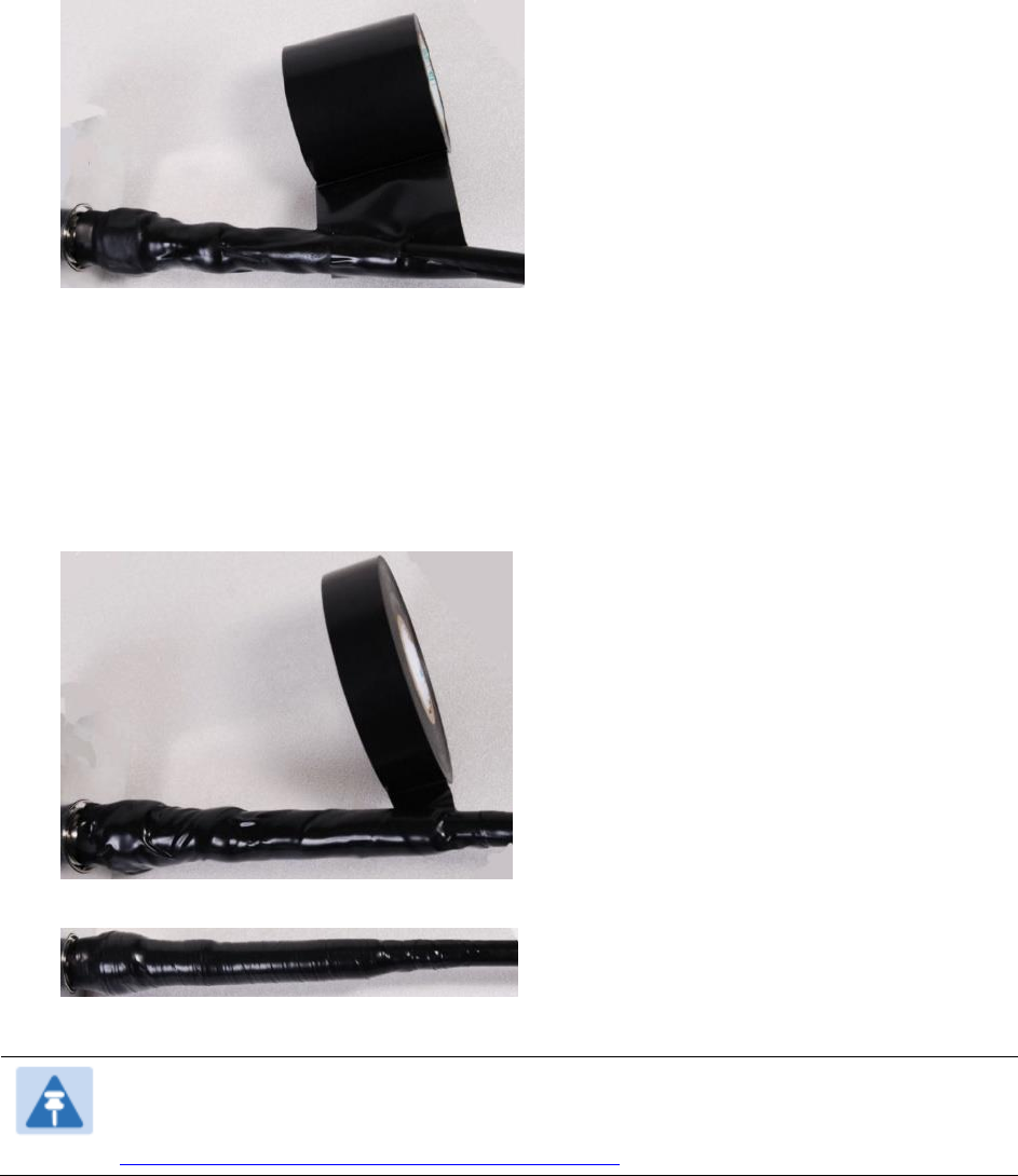
7
Wrap a layer of 50 mm (2 inch) PVC tape from bottom to top, starting from 25 mm (1 inch)
below the edge of the self-amalgamating tape, overlapping at half width.
8
Repeat with a further four layers of 19 mm (0.75 inch) PVC tape, always overlapping at half
width. Wrap the layers in alternate directions:
Second layer: top to bottom.
Third layer: bottom to top.
Fourth layer: top to bottom.
Fifth layer: bottom to top.
The bottom edge of each layer should be 25 mm (1 inch) below the previous layer.
9
Check the completed weatherproof connection:
Note
A video of this procedure can be found at:
https://www.youtube.com/watch?v=a-twPfCVq4A