Cambium Networks 50450M 5GHz Point to MultiPoint Multi User MIMO Access Point User Manual USERS MANUAL PART3
Cambium Networks Limited 5GHz Point to MultiPoint Multi User MIMO Access Point USERS MANUAL PART3
Contents
- 1. USER GUIDE P1
- 2. USER GUIDE P2
- 3. USER GUIDE P3
- 4. USER GUIDE P4
- 5. User manual
- 6. User Manual
- 7. USERS MANUAL PART1
- 8. USERS MANUAL PART2
- 9. USERS MANUAL PART3
- 10. USERS MANUAL PART4
- 11. USER MANUAL PART1
- 12. USER MANUAL PART2
- 13. USER MANUAL PART 3
- 14. USER MANUAL PART 4
- 15. USER MANUAL PT1
- 16. USER MANUAL PT2
- 17. USER MANUAL PT3
USERS MANUAL PART3
Chapter 7: Configuration Configuring radio parameters
Page 7-164
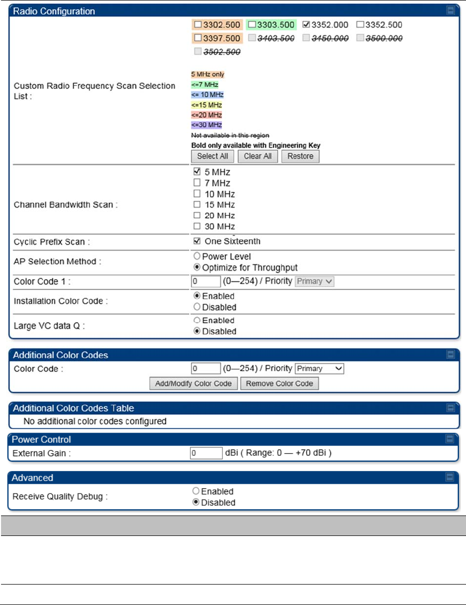
Radio page - PMP 450 SM 3.5 GHz
Table 154
PMP 450 SM
Radio attributes – 3.5 GHz
Attribute Meaning
Custom Radio
Frequency Scan
Selection List
Check the frequencies that SM has to scan for AP transmissions. See Radio
Frequency Scan Selection List on page 7-169.
See Table 142 PMP 450i AP Radio attributes - 5
GHz on page 7-132.
Chapter 7: Configuration Configuring radio parameters
Page 7-165
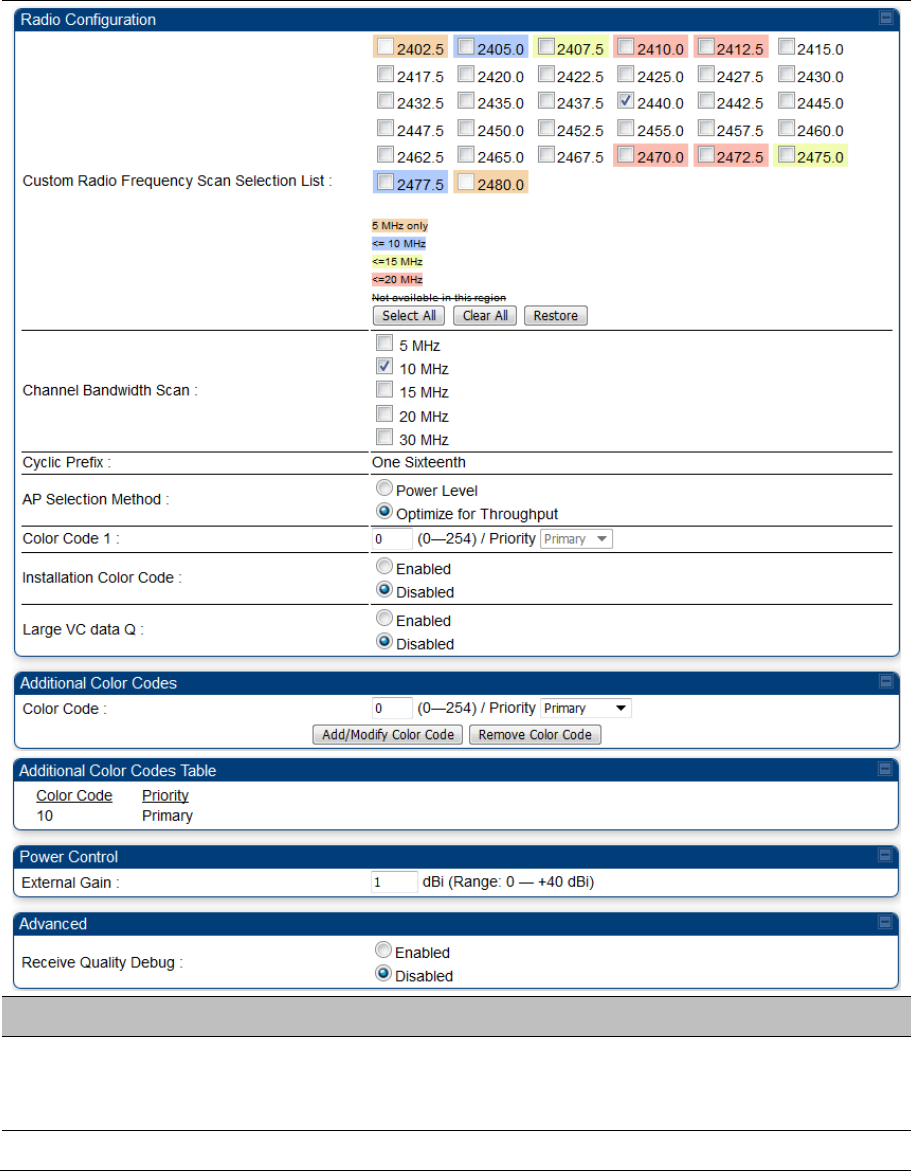
Radio page - PMP 450 SM 2.4 GHz
Table 155 PMP 450 SM Radio attributes – 2.4 GHz
Attribute Meaning
Custom Radio
Frequency Scan
Selection List
Check the frequencies that SM has to scan for AP transmissions. See Radio
Frequency Scan Selection List on page 7-169.
See Table 142 PMP 450i AP Radio attributes - 5 GHz on page 7-132.
Chapter 7: Configuration Configuring radio parameters
Page 7-166
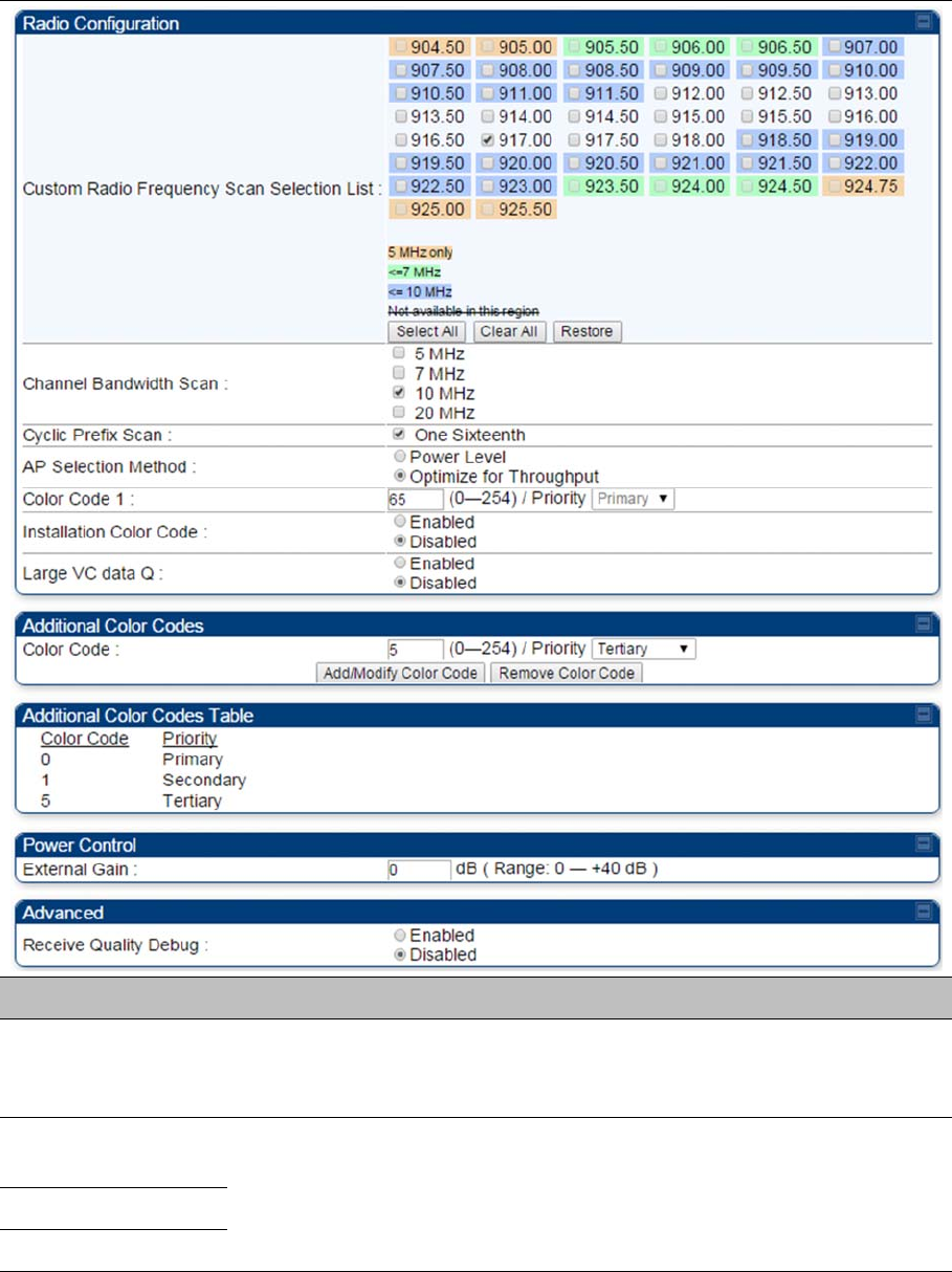
Radio page - PMP 450 SM 900 MHz
Table 156
PMP 450 SM
Radio attributes –900 MHz
Attribute Meaning
Custom Radio
Frequency Scan
Selection List
See Table 142 PMP 450i AP Radio attributes - 5
GHz on page 7-132.
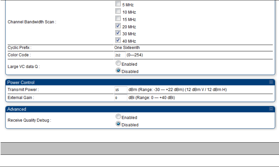
Channel Bandwidth
Scan
See Table 142 PMP 450i AP Radio attributes - 5
GHz on page 7-132.
Cyclic Prefix Scan
AP Selection Method

Chapter 7: Configuration Configuring radio parameters
Page 7-167
Color Code 1
Installation Color
Code
Large VC data Queue
Color Code
External Gain See Table 142 PMP 450i AP Radio attributes - 5 GHz on page 7-132
Receive Quality
Debug
See Table 142 PMP 450i AP Radio attributes - 5 GHz on page 7-132.
Note
The frequencies that a user can select are controlled by the country or a region and the
Channel Bandwidth selected. There can be a case where a user adds a custom frequency
(from the Custom Frequencies page on page 7-172) and cannot see it in the pull down
menu.
Chapter 7: Configuration Configuring radio parameters
Page 7-168
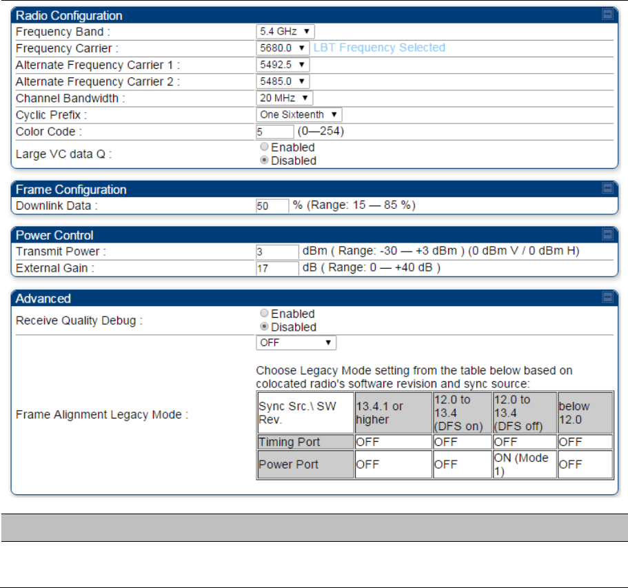
Radio page - PTP 450 BHM 5 GHz
Table 157 PTP 450 BHM Radio attributes –5 GHz
Attribute Meaning
Refer Table 145 PTP 450i BHM Radio page attributes – 5 GHz on page 7-145 for all parameters
details.
Chapter 7: Configuration Configuring radio parameters
Page 7-169
Radio page - PTP 450 BHS 5 GHz
Table 158 PTP 450 BHM Radio attributes –5 GHz
Chapter 7: Configuration Configuring radio parameters
Page 7-170
Attribute Meaning
Refer Table 146 PTP 450i BHS Radio attributes – 5 GHz on page 7-148 for all parameters details.
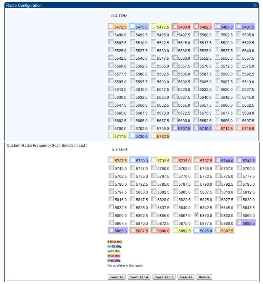
Radio Frequency Scan Selection List
The SM or BHS scans complete spectrum as per Full Spectrum Band Scan feature. SMs or BHS first
boot into the smallest selected channel bandwidth (10 MHz, if selected) and scan all selected frequencies
across both the 5.4 GHz and 5.7 GHz frequency bands.
After this scan, if a wider channel bandwidth is selected (20 MHz), the SM/BHS automatically changes to
20 MHz channel bandwidth and then scans for APs/BHSs. After the SM/BHS finishes this final scan it will
evaluate the best AP/BHM with which to register. If required for registration, the SM/BHS changes its
channel bandwidth back to 10 MHz to match the best AP/BHM.
The SM/BHS will attempt to connect to an AP/BHM based on power level (which affects the modulation
state), channel bandwidth (which affects throughput) and number of SM/BHS registrations to the AP/BHM
(which affects system contention performance).
If it is desired to prioritize a certain AP/BHM over other available APs/BHMs, operators may use the Color
Code Priority feature on the SM/BHS. Utilization of the Color Code feature on the AP/BHM is
recommended to further constrain the AP selection.
If the SM does not find any suitable APs/BHMs for registration after scanning all channel bandwidths, the
SM restarts the scanning process beginning with the smallest configured channel bandwidth.
Selecting multiple frequencies and multiple channel bandwidths impacts the SM/BHS scanning time. The
biggest consumption of time is in the changing of the SM/BHS channel bandwidth setting.
The worst case scanning time is approximately two minutes after boot up (SM/BHS with all frequencies
and channel bandwidths selected and registering to an AP/BHM at 10 MHz). If only one channel
bandwidth is selected the time to scan all the available frequencies and register to an AP/BHM is
approximately one minute after boot up.
Other scanning features such as Color Code, Installation Color Code, and RADIUS authentication are
unaffected by the Full Band Scan feature.
Chapter 7: Configuration Configuring radio parameters
Page 7-171
Dedicated Multicast Virtual Circuit (VC)
A Multicast VC allows to configure multicast packets to be transmitted over a dedicated channel at a
configurable rate of 1X, 2X, 4X or 8X. This feature is available only for the PMP 450 and PMP 450i and is
not backward compatible with PMP 430 series of radios.
To configure Multicast VC, the AP must have this enabled. This can be enabled in the “Multicast Data
Control” section (under Configuration > Radio page). The default value is “Disable”. If set to the default
value, all multicast packets are transmitted over the Broadcast VC data path. To enable, select the data
rate that is desired for the Multicast VC Data Rate parameter and click Save Changes button. The radio
requires no reboot after any changes to this parameter.
The multicast VC allows three different parameters to be configured on the AP. These can be changed on
the fly and are saved on the flash memory.
Note
If the Multicast VC Data Rate is set to a modulation that the radio is not currently capable of
or operates in non-permitted channel conditions, multicast data is sent but not received.
Ex: If Multicast VC Data Rate is set to 6x and the channel conditions only permit 4x mode of
operation, then multicast data is sent at 6x modulation but the SM will not receive the data.
Note
The PMP 450 AP supports up to 119 VCs (instead of 238 VCs) when configured for 30
MHz channel bandwidth or 5 ms Frame Period. This limitation is not applicable for
PMP 450i/450m Series.
Note
Actual Multicast CIR honored by the AP = Configured Multicast CIR/ (Multicast Repeat
Count + 1).
Increasing the Multicast data rate has no impact on the Unicast data rate.
For multicast and unicast traffic mix scenario examples, see Table 159.
Table 159 Example for mix of multicast and unicast traffic scenarios
Repeat
Count
Multicast Data
Rate (Mbps)
Unicast Data
Rate (Mbps)
Aggregate DL Data
Rate (Mbps)
0 10 40 50
1 5 40 45
2 3.33 40 43.33
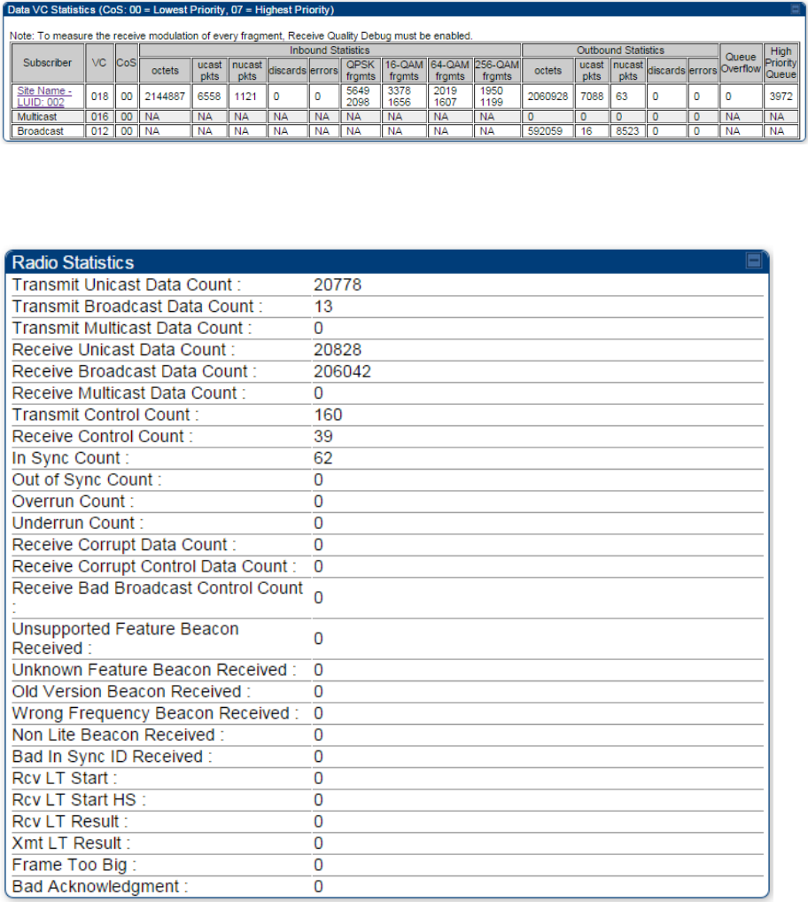
The statistics have been added to the Data VC page (under Statistics > Data VC). The table displays the
multicast row on the PMP 450 Platform Family AP. The SM displays the multicast row if it is a PMP 450
Platform Family.
Chapter 7: Configuration Configuring radio parameters
Page 7-172
Figure 144 Multicast VC statistics
The AP and SM display Transmit and Receive Multicast Data Count (under the Statistics > Scheduler
page), as shown in Figure 145.
Figure 145 Multicast scheduler statistics
Chapter 7: Configuration Configuring radio parameters
Page 7-173
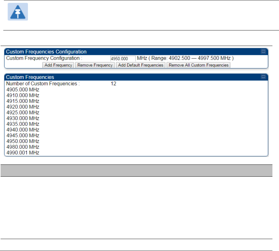
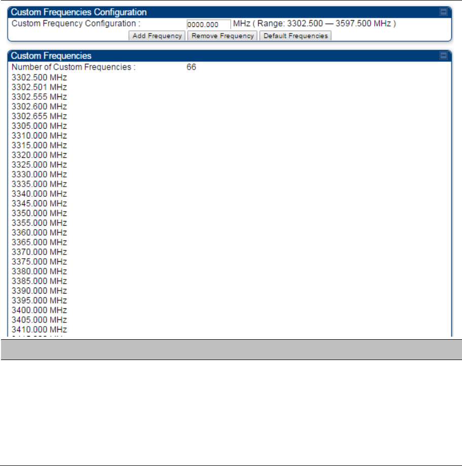
Custom Frequencies page
In addition to the Radio tab, AP/SM/BH has another tab called Custom Frequencies as shown in Table
160.
The custom frequency tab allows to configure custom frequency at 1 KHz raster. It means that the custom
frequencies can be at granularity of 1 KHz e.g. 4910.123 MHz, 4922.333 MHz, 4933.421 MHz etc.
Note
Ensure that a customer frequency exists before using SNMP to set the radio to a Custom
Frequency.
Table 160 450 Platform Family AP/SM/BH Custom Frequencies page – 5 GHz
Attribute Meaning
Custom Frequency
Configuration
Custom frequencies with a channel raster of 1 KHz can be added from the
available range by keying in the frequency and then clicking the Add
Frequency button. Click Remove Frequency button to delete a specific
frequency keyed in the text box.
Click Default Frequencies button to add a pre-defined list of frequencies that
can be used in this band. This list can be reduced or increased by manually
removing or adding other custom frequencies.
Custom Frequencies Displays the complete list of user configured custom frequencies.
Chapter 7: Configuration Configuring radio parameters
Page 7-174
Table 161 PMP/PTP 450 SM/BH Custom Frequencies page – 3.65 GHz
Attribute Meaning
Custom Frequency
Configuration
Custom frequencies with a channel raster of 1 KHz can be added from the
available range by keying in the frequency and then clicking the Add
Frequency button. Click Remove Frequency button to delete a specific
frequency keyed in the text box.
Click Default Frequencies button to add a pre-defined list of frequencies that
can be used in this band. This list can be reduced or increased by manually
removing or adding other custom frequencies.
Custom Frequencies Displays the complete list of user configured custom frequencies.
Chapter 7: Configuration Configuring radio parameters
Page 7-175
Table 162 PMP/PTP 450 SM/BH Custom Frequencies page – 3.5 GHz
Attribute Meaning
Custom Frequency
Configuration
Custom frequencies with a channel raster of 1 KHz can be added from the
available range by keying in the frequency and then clicking the Add
Frequency button. Click Remove Frequency button to delete a specific
frequency keyed in the text box.
Click Default Frequencies button to add a pre-defined list of frequencies that
can be used in this band. This list can be reduced or increased by manually
removing or adding other custom frequencies.
Chapter 7: Configuration Configuring radio parameters
Page 7-176
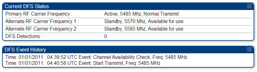
DFS for 5 GHz Radios
Dynamic Frequency Selection (DFS) is a requirement in several countries and regions for 5 GHz
unlicensed systems to detect radar systems and avoid co-channel operation. DFS and other regulatory
requirements drive the settings for the following parameters, as discussed in this section:
Country Code
Primary Frequency
Alternate 1 and Alternate 2 Frequencies
External Antenna Gain
On the AP, the Home > DFS Status page shows current DFS status of all three frequencies and a DFS
log of past DFS events.
Figure 146 AP DFS Status
DFS operation
The ODUs use region-specific DFS based on the Country Code selected on the module’s Configuration,
General page. By directing installers and technicians to set the Country Code correctly, the operator
gains confidence the module is operating according to national or regional regulations without having to
deal with the details for each region.
The details of DFS operation for each Country Code, including whether DFS is active on the AP, SM, and
which DFS regulations apply is shown in Table 259 on page 10-47.
Chapter 7: Configuration Configuring radio parameters
Page 7-177
Contention slots
The SM uses reserved Contention slots and unused data slots for bandwidth requests.
Uplink Data Slots are used first for data. If they are not needed for data in a given frame, the remaining
data slots can be used by the SMs for bandwidth requests. This allows SMs in sectors with a small
number of Contention slots configured to still successfully transmit bandwidth requests using unused data
slots.
A higher number of Contention slots give higher probability that a SM’s bandwidth request is correctly
received when the system is heavily loaded, but with the tradeoff that sector capacity is reduced, so there
is less capacity to handle the request. The sector capacity reduction is about 200 kbps for each
Contention slot configured in a 20 MHz channel at QPSK MIMO-A modulation. The reduction in sector
capacity is proportionally higher at MIMO-B modulations (2 times at QPSK MIMO-B, 4 times at 16 QAM
MIMO-B, 6 times at 64 QAM MIMO-B and 8 times at 256 QAM MIMO-B). If very few reserved Contention
slots are specified, then latency increases in high traffic periods. If too many are specified, then the
maximum capacity is unnecessarily reduced.
The suggested Contention slot settings as a function of the number of active SMs in the sector are shown
in the table below.
Table 163 Contention slots and number of SMs
Number of SMs Recommended Number of Contention slots
1 to 10 3
11 to 50 4
51 to 150 6
151 and above 8
In a typical cluster, each AP must be set to the same number of Contention slots to assure proper timing
in the send and receive cycles. However, where high incidence of small packets exists, as in a sector that
serves several VoIP streams, additional Contention slots may provide better results. For APs in a cluster
of mismatched Contention slots setting, or where PMP 450/450i Series is collocated with radios using
different technologies, like PMP 430 or FSK, in the same frequency band, use the frame calculator. To
download the PMP 450 Contention Slots Paper, see
http://www.cambiumnetworks.com/solution-papers/pmp-450-contention-slots.
For co-location of radios with mismatched configuration parameters, see the co-location tool available
here:
https://support.cambiumnetworks.com/files/colocationtool/
Chapter 7: Configuration Configuring radio parameters
Page 7-178
MIMO-A mode of operation
450 Platform Family supports MIMO-B mode using the following modulation levels: QPSK, 16-QAM, 64-
QAM and 256-QAM. System Release 13.2 introduces MIMO-A mode of operation using the same
modulation levels as the MIMO-B mode. With MIMO-B, the radio sends different streams of data over the
two antennas whereas with MIMO-A, the radio uses a scheme that tries to optimize coverage by
transmitting the same data over both antennas. This redundancy improves the signal to noise ratio at the
receiver making it more robust, at the cost of throughput.
In addition to introducing MIMO-A modes, improvements have been made to the existing rate adapt
algorithm to switch between MIMO-A and MIMO-B seamlessly without any intervention or added
configuration by the operator. The various modulation levels used by the 450 Platform Family are shown
in Table 164.
Table 164 450 Platform Family Modulation levels
Rate MIMO-B MIMO-A
QPSK 2X MIMO-B 1X MIMO-A
16-QAM 4X MIMO-B 2X MIMO-A
64-QAM 6X MIMO-B 3X MIMO-A
265-QAM 8X MIMO-B 4X MIMO-A
System Performance
For System Performance details of all the 450 Platform Family ODUs, refer to the tools listed below:
Link Capacity Planner for PMP/PTP 450 and 450i:
https://support.cambiumnetworks.com/files/capacityplanner/
LINKPlanner for PMP/PTP 450/450i and PMP 450m:
https://support.cambiumnetworks.com/files/linkplanner/

Chapter 7: Configuration Configuring radio parameters
Page 7-179
Table 165 Co-channel Interference per (CCI) MCS
MCS of Victim MCS of Interferer Channel BW (MHz) CCI
1X (QPSK SISO) 6X (64-QAM MIMO-B) 5, 7, 10, 15, 20, 30,
or 40
10 dB
2X (16-QAM SISO) 6X (64-QAM MIMO-B) 5, 7, 10, 15, 20, 30,
or 40
17 dB
3X (64-QAM SISO) 6X (64-QAM MIMO-B) 5, 7, 10, 15, 20, 30,
or 40
25 dB
1X (QPSK MIMO-A) 6X (64-QAM MIMO-B) 5, 7, 10, 15, 20, 30,
or 40
7 dB
2X (16-QAM MIMO-A) 6X (64-QAM MIMO-B) 5, 7, 10, 15, 20, 30,
or 40
14 dB
3X (64-QAM MIMO-A) 6X (64-QAM MIMO-B) 5, 7, 10, 15, 20, 30,
or 40
22 dB
4X (256-QAM MIMO-A) 6X (64-QAM MIMO-B) 5, 7, 10, 15, 20, 30,
or 40
30 dB
2X (QPSK MIMO-B) 6X (64-QAM MIMO-B) 5, 7, 10, 15, 20, 30,
or 40
10 dB
4X (16-QAM MIMO-B) 6X (64-QAM MIMO-B) 5, 7, 10, 15, 20, 30,
or 40
17 dB
6X (64-QAM MIMO-B) 6X (64-QAM MIMO-B) 5, 7, 10, 15, 20, 30,
or 40
25 dB
8X (256-QAM MIMO-B) 6X (64-QAM MIMO-B) 5, 7, 10, 15, 20, 30,
or 40
33 dB
Table 166 Adjacent Channel Interference (ACI) per MCS
MCS of Victim MCS of Interferer Channel BW (MHz) ACI Guard Band
1X (QPSK SISO) 6X (64-QAM MIMO-B) 5, 7, 10, 15, 20, 30,
or 40 -16 dB None
2X (16-QAM SISO) 6X (64-QAM MIMO-B) 5, 7, 10, 15, 20, 30,
or 40 -16 dB None
3X (64-QAM SISO) 6X (64-QAM MIMO-B) 5, 7, 10, 15, 20, 30,
or 40 -16 dB None
1X (QPSK MIMO-A) 6X (64-QAM MIMO-B) 5, 7, 10, 15, 20, 30,
or 40 -13 dB None
2X (16-QAM MIMO-A) 6X (64-QAM MIMO-B) 5, 7, 10, 15, 20, 30,
or 40 -13 dB None
Chapter 7: Configuration Configuring radio parameters
Page 7-180
3X (64-QAM MIMO-A) 6X (64-QAM MIMO-B) 5, 7, 10, 15, 20, 30,
or 40 -13 dB None
4X (256-QAM MIMO-A) 6X (64-QAM MIMO-B) 5, 7, 10, 15, 20, 30,
or 40 -10 dB None
2X (QPSK MIMO-B) 6X (64-QAM MIMO-B) 5, 7, 10, 15, 20, 30,
or 40 -16 dB None
4X (16-QAM MIMO-B) 6X (64-QAM MIMO-B) 5, 7, 10, 15, 20, 30,
or 40 -16 dB None
6X (64-QAM MIMO-B) 6X (64-QAM MIMO-B) 5, 7, 10, 15, 20, 30,
or 40 -16 dB None
8X (256-QAM MIMO-B) 6X (64-QAM MIMO-B) 5, 7, 10, 15, 20, 30,
or 40 -10 dB None
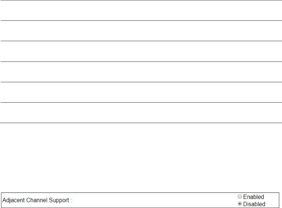
Guard Band
When synchronized, no Guard Bands are needed for the 450* and 450i Series.
* For PMP 450 AP (3.6 GHz) and 450 platform APs with 450b SM (5 GHz) connected, Configuration -> Radio ->
Power Control -> Adjacent Channel Support must be enabled.
Improved PPS performance of 450 Platform Family
The 450m, 450i, and 450b Series provides improved packets per second (PPS) performance compared
to 450 Series.
Through hardware and software enhancements, the PPS performance of the PMP 450i Series AP and
PMP 450b SM has been improved to 40k packets/second, measured through a standard RFC2544 test
using 64 bytes packets. With this enhancement, operators are able to provide higher bandwidth including
better VoIP and video services to end customers using existing SM deployments.
PMP 450m supports 100k packets/second.

Chapter 7: Configuration Setting up SNMP agent
Page 7-181
Setting up SNMP agent
Operators may use SNMP commands to set configuration parameters and retrieve data from the AP and
SM modules. Also, if enabled, when an event occurs, the SNMP agent on the 450 Platform Family sends
a trap to whatever SNMP trap receivers configured in the management network.
SNMPv2c
SNMPv3
Chapter 7: Configuration Setting up SNMP agent
Page 7-182
Configuring SM/BHS’s IP over-the-air access
To access the SM/BHS management interface from a device situated above the AP, the SM/BHS’s
Network Accessibility parameter (under the web GUI at Configuration > IP) may be set to Public.
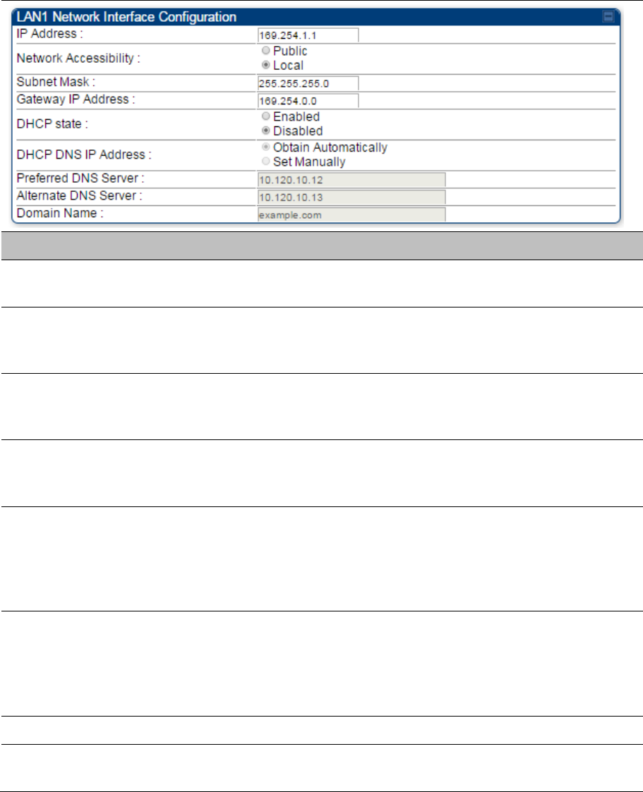
Table 167 LAN1 Network Interface Configuration tab of IP page attributes
Attribute Meaning
IP Address Internet Protocol (IP) address. This address is used by family of Internet
protocols to uniquely identify this unit on a network.
Network Accessibility
Specify whether the IP address of the SM/BHS must be visible to only a
device connected to the SM/BHS by Ethernet (Local) or be visible to the
AP/BHM as well (Public).
Subnet Mask
If Static IP is set as the Connection Type of the WAN interface, then this
parameter configures the subnet mask of the SM/BHS for RF management
traffic.
Gateway IP Address
If Static IP is set as the Connection Type of the WAN interface, then this
parameter configures the gateway IP address for the SM/BHS for RF
management traffic.
DHCP state
If Enabled is selected, the DHCP server automatically assigns the IP
configuration (IP address, subnet mask, and gateway IP address) and the
values of those individual parameters (above) are not used. The setting of this
DHCP state parameter is also viewable (read only), in the Network Interface
tab of the Home page.
DNS IP Address
Canopy devices allow for configuration of a preferred and alternate DNS
server IP address either automatically or manually. Devices must set DNS
server IP address manually when DHCP is disabled for the management
interface of the device. The default DNS IP addresses are 0.0.0.0 when
configured manually.
Preferred DNS Server The first address used for DNS resolution.
Alternate DNS Server If the Preferred DNS server cannot be reached, the Alternate DNS Server is
used.

Chapter 7: Configuration Setting up SNMP agent
Page 7-183
Domain Name
The operator’s management domain name may be configured for DNS. The
domain name configuration can be used for configuration of the servers in the
operator’s network. The default domain name is example.com, and is only
used if configured as such.
Chapter 7: Configuration Setting up SNMP agent
Page 7-184
Configuring SNMP
The SNMP page configuration is explained below.
Note
The SNMP page for AP, SM, BHM and BHS has the same parameter attributes.
SNMP page – AP/SM/BHM/BHS
The SNMP page is explained in Table 168.
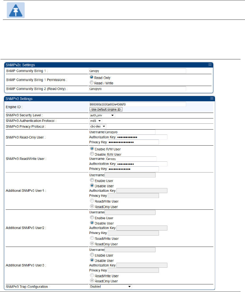
Table 168 SNMP page attributes
Chapter 7: Configuration Setting up SNMP agent
Page 7-185
Attribute Meaning
SNMP Community
String 1
Specify a control string that can allow a Network Management Station (NMS)
to access SNMP information. No spaces are allowed in this string. The default
string is Canopy.
SNMP Community
String 1 Permissions
You can designate the SNMP Community String 1 to be the password for
WM, for example, to have Read / Write access to the module via SNMP or for
all SNMP access to the module to be Read Only.
SNMP Community
String 2 (Read Only)
Specify an additional control string that can allow a Network Management
Station (NMS) to read SNMP information. No spaces are allowed in this
string. The default string is Canopyro. This password will never authenticate
a user or an NMS to read/write access.

Chapter 7: Configuration Setting up SNMP agent
Page 7-186
The Community String value is clear text and is readable by a packet
monitor. Additional security derives from the configuration of the Accessing
Subnet, Trap Address, and Permission parameters.
Engine ID The Engine ID may be between 5 and 32 hex characters. The hex character
input is driven by RFC 3411 recommendations on the Engine ID. The default
Engine ID is the MAC address of the device
SNMPv3 Security
Level
Specify security model where users are defined and authenticated before
granting access to any SNMP service. Each device can configure the security
level of SNMPv3 to No authentication/No privacy, Authentication/No privacy,
or Authentication/Privacy.
SNMPv3
Authentication
Protocol
Currently, the SNMPv3 authentication protocol MD5 is supported.
SNMPv3 Privacy
Protocol
Currently, the SNMPv3 privacy protocol CBC-DES is supported.
SNMPv3 Read-Only
User
This field allows for a read-only user per devices. The default values for the
Read-Only users is:
Username = Canopyro
Authentication Password = authCanopyro
Privacy Password = privacyCanopyro
SNMPv3 Read/Write
User
Read-write user by default is disabled. The default values for the Read/Write
users is :
Username = Canopy
Authentication Password = authCanopy
Privacy Password = privacyCanopy
Additional SNMP v3
User 1
This field allows to configure the Additional SNMP v3 User 1. The
configurations include:
Enable/Disable User: These fields allow to enable or disable the user
using the Enable User or Disable User radio buttons.
Authorizaton Key: This field allows to configure an authorization key for
the user.
Privacy Key: This field allows to configure a privacy key for the user.
Note:
Set SNMP v3 Security Level field to :auth,priv to enable the
Authorization Key and Privacy Key fields.
Enabled User can be set with following privacy settings:
ReadWrite User
ReadOnly User

Chapter 7: Configuration Setting up SNMP agent
Page 7-187
Additional SNMP v3
User 2
This field allows to configure the Additional SNMP v3 User 2.
The configurations include:
Enable/Disable User: These fields allow to enable or disable the user
using the Enable User or Disable User radio buttons.
Authorizaton Key: This field allows to configure an authorization key for
the user.
Privacy Key: This field allows to configure a privacy key for the user.
Set SNMP v3 Security Level field to :auth,priv to enable the
Authorization Key and Privacy Key fields.
Enabled User can be set with following Privacy settings:
ReadWrite User
ReadOnly User
Additional SNMP v3
User 3
This field allows to configure the Additional SNMP v3 User 3.
The configurations include:
Enable/Disable User: These fields allow to enable or disable the user
using the Enable User or Disable User radio buttons.
Authorizaton Key: This field allows to configure an authorization key for
the user.
Privacy Key: This field allows to configure a privacy key for the user.
Set SNMP v3 Security Level field to :auth,priv to enable the
Authorization Key and Privacy Key fields.
Enabled User can be set with following Privacy settings:
ReadWrite User
ReadOnly User
SNMPv3 Trap
Configuration
When enabling transmission of SNMPv3 traps the read-only or read-write
user credentials must be used and selected properly in order for the SNMP
manager to correctly interpret the traps. By default transmission of SNMPv3
traps is disabled and all traps sent from the radios are in SNMPv2c format.
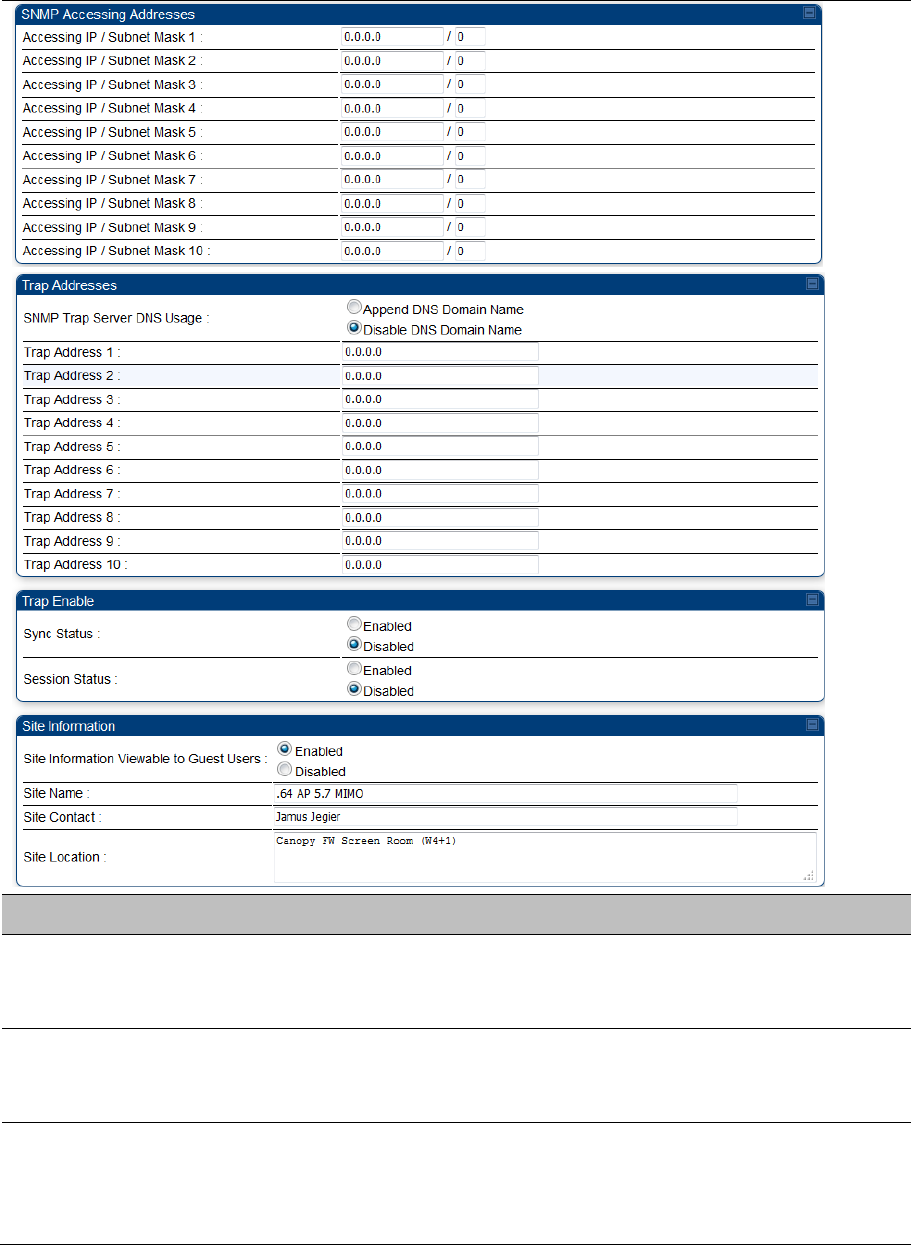
Accessing IP / Subnet
Mask
1 to 10
Specify the addresses that are allowed to send SNMP requests to this AP.
The NMS has an address that is among these addresses (this subnet). You
must enter both
The network IP address in the form xxx.xxx.xxx.xxx
The CIDR (Classless Interdomain Routing) prefix length in the form /xx
For example:
the /16 in 198.32.0.0/16 specifies a subnet mask of 255.255.0.0 (the first
16 bits in the address range are identical among all members of the
subnet).
192.168.102.0 specifies that any device whose IP address is in the range
192.168.102.0 to 192.168.102.254 can send SNMP requests to the AP,
presuming that the device supplies the correct
Community String
value.

Chapter 7: Configuration Setting up SNMP agent
Page 7-188
The default treatment is to allow all networks access. For more information on
CIDR, execute an Internet search on “Classless Interdomain Routing.” You
are allowed to specify as many as 10 different accessing IP address, subnet
mask combinations.
RECOMMENDATION:
The subscriber can access the SM/BHS by changing the subscriber device to
the accessing subnet. This hazard exists because the Community String
and Accessing Subnet are both visible parameters. To avoid this hazard,
configure the SM/BHS to filter (block) SNMP requests.
SNMP Trap Server
DNS Usage
The management DNS domain name may be toggled such that the name of
the trap server only needs to be specified and the DNS domain name is
automatically appended to that name. The default SNMP trap server
addresses for all 10 available servers is 0.0.0.0 with the appending of the
DNS domain name disabled.
Trap Address 1 to 10 Specify ten or fewer IP addresses (xxx.xxx.xxx.xxx) or DNS names to which
SNMP traps must be sent. Traps inform Wireless Manager or an NMS that
something has occurred. For example, trap information is sent
after a reboot of the module.
when an NMS attempts to access agent information but either
supplied an inappropriate community string or SNMP version number.
is associated with a subnet to which access is disallowed.
Trap Enable, Sync
Status
If the sync status traps (sync lost and sync regained) have to be sent to
Wireless Manager or an NMS, select Enabled. If these traps have to be
suppressed, select Disabled.
Trap Enable, Session
Status
If you want session status traps sent to Wireless Manager or an NMS, select
Enabled.
Site Information
Viewable to Guest
Users
Operators can enable or disable site information from appearing when a user
is in GUEST account mode.
Site Name Specify a string to associate with the physical module. This parameter is
written into the sysName SNMP MIB-II object and can be polled by Wireless
Manager or an NMS. The buffer size for this field is 128 characters.
Site Contact Enter contact information for the module administrator. This parameter is
written into the sysContact SNMP MIB-II object and can be polled by Wireless
Manager or an NMS. The buffer size for this field is 128 characters.
Site Location Enter information about the physical location of the module. This parameter is
written into the sysLocation SNMP MIB-II object and can be polled by
Wireless Manager or an NMS. The buffer size for this field is 128 characters.

Chapter 7: Configuration Configuring syslog
Page 7-189
Configuring syslog
450 Platform Family includes:
Syslog event logging
Configuring system logging
Chapter 7: Configuration Configuring syslog
Page 7-190
Syslog event logging
Following events are logged in syslog as explained in Table 169.
Table 169 Syslog parameters
Attribute Meaning
Timestamp All syslog messages captured from the radio have a timestamp.
Configuration
Changes
This includes any device setting that has changed and includes the old or
new parameter value, including the device reboots.
User Login and
Logout Syslog records each user login and logout, with username.
Add or Delete of user
accounts through GUI
and SNMP
Syslog captures any user accounts that are added or deleted.
Spectrum Analysis Syslog records a message every time Spectrum Analysis runs.
Note
Since the AP/BHM must be set to a SM/BHS for Spectrum
Analysis, syslog messages are not reported from the radio until
the scan is done and the radio mode is switched back to
AP/BHM.
Link Test Syslog records a message every time a Link Test is run.
Clear Statistics Syslog sends a message when Statistics are cleared. This is done individually
for each statistics page that is cleared.
SM Register or De-
register Syslog records a message when a SM registers or deregisters.
BHS Connect or
Disconnect Syslog records a message when a BHS connects or disconnects.
Configuring system logging
To configure system logging, select the menu option Configuration > Syslog.
Syslog page of AP/BHM
The Syslog Configuration page for AP/BHM is shown in Table 170.
Chapter 7: Configuration Configuring syslog
Page 7-191
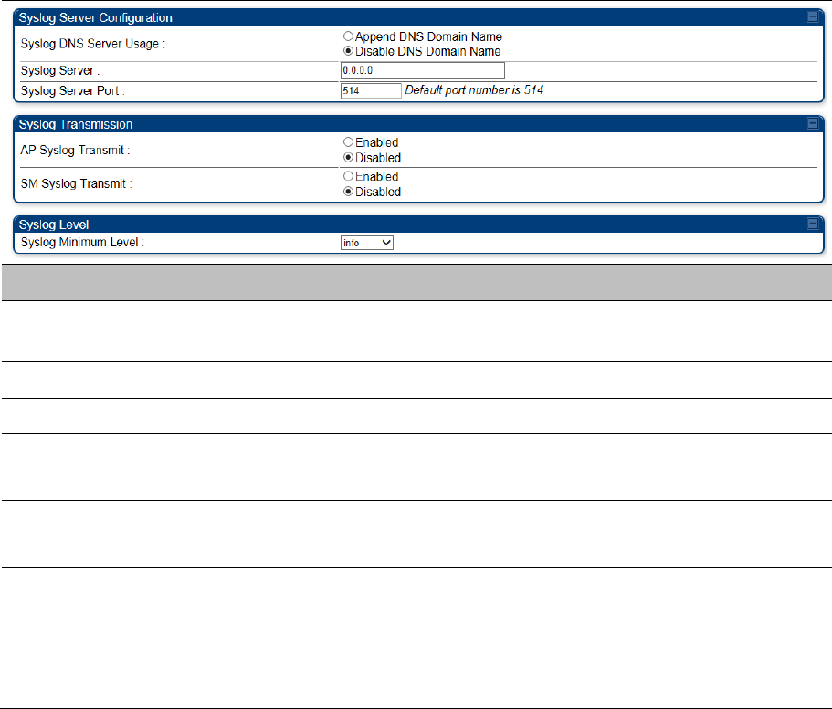
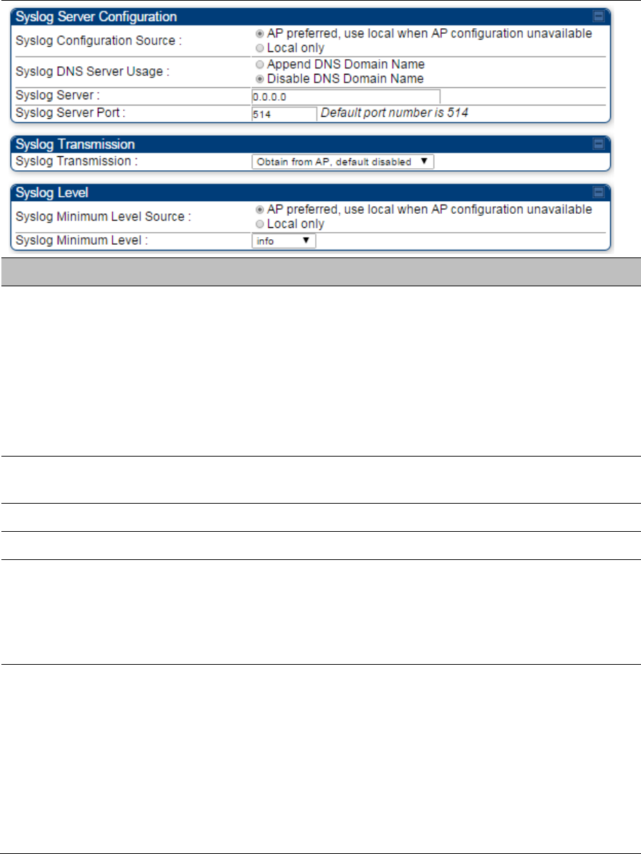
Table 170 Syslog Configuration attributes - AP
Attribute Meaning
Syslog DNS Server Usage To configure the AP/BHM to append or not append the DNS server
name to the syslog server name.
Syslog Server The dotted decimal or DNS name of the syslog server address.
Syslog Server Port The syslog server port (default 514) to which syslog messaging is sent.
AP Syslog Transmit
Or BHM Syslog Transmit When enabled, syslog messages are sent from the AP/BHM.
SM Syslog Transmit
Or BHS Syslog Transmit
When enabled, syslog messages are sent from all the registered
SMs/BHS, unless they are individually set to override this.
Syslog Minimum Level
This provides a selection for the minimum syslog message severity that
is sent to the syslog server. Values range from fatal (highest severity
and least verbose) to info (lowest severity, maximum verbosity).
For example: If the Syslog Minimum Level is set to notice, then only
messages with severity notice and above are sent.
Syslog page of SM
To configure system logging, select the menu option Configuration > Syslog. The Syslog Configuration
page is shown in Table 171.
Chapter 7: Configuration Configuring syslog
Page 7-192
Table 171 Syslog Configuration attributes - SM
Attribute Meaning
Syslog Configuration
Source
This control determines whether the SM will attempt to use the syslog server
definition from the AP, or whether it will use a local server definition.
When set to AP preferred, use local when AP configuration unavailable,
and if the SM can register with an AP, then it uses the syslog server defined
on that AP. If the SM cannot register then it will syslog to its locally defined
syslog server through its wired connection, if any.
When set to Local only the SM ignores the AP’s definition of the syslog
server and allows the syslog server to be configured individually for each SM.
Syslog DNS Server
Usage
To configure the SM to append or not the DNS server name to the syslog
server name.
Syslog Server The dotted decimal or DNS name of the syslog server address.
Syslog Server Port The syslog server port (default 514) to which syslog messaging is sent.
Syslog Transmission Controls the SMs ability to transmit syslog messages. When set to “Learn
from AP” the AP will control whether this SM transmits syslog messages.
When set to “enable” or “disable” the SM will control whether it sends syslog
messages. This allows an operator to override the AP settings for individual
SMs in a sector.
Syslog Minimum Level
Source
This control determines whether the SM attempts to use the minimum syslog
level defined by the AP, or whether it uses a local defined value using the
“Syslog Minimum Level” parameter.
When set to “AP preferred, use local when AP configuration unavailable”, and
if the SM can register with an AP, then it uses the Syslog Minimum Level
defined on that AP. If the SM cannot register then it uses its own Syslog
Minimum Level setting.
When set to “Local only” the SM will always use its own Syslog Minimum
Level setting and ignores the AP’s setting.
Chapter 7: Configuration Configuring syslog
Page 7-193
Syslog Minimum Level
This provides a selection for the minimum syslog message severity that is
sent to the syslog server. Values range from fatal (highest severity and least
verbose) to info (lowest severity, maximum verbosity).
For example: If the Syslog Minimum Level is set to notice, then only
messages with severity notice and above are sent.
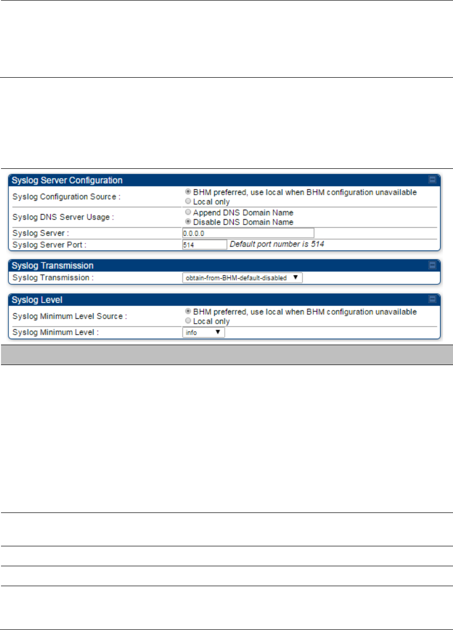
Syslog page of BHS
The Syslog Configuration page is shown in Table 172.
Table 172 Syslog Configuration attributes - BHS
Attribute Meaning
Syslog Configuration
Source
This control determines whether the BHS will attempt to use the syslog server
definition from the BHM, or whether it will use a local server definition.
When set to BHM preferred, use local when BHM configuration
unavailable, and if the BHS can register with a BHM, then it uses the
syslog server defined on that BHM. If the BHS cannot register then it will
syslog to its locally defined syslog server through its wired connection, if
any.
When set to Local only the BHS ignores the BHM’s definition of the
syslog server and allows the syslog server to be configured individually
for each BHS.
Syslog DNS Server
Usage
To configure the BHS to append or not to append the DNS server name to
the syslog server name.
Syslog Server The dotted decimal or DNS name of the syslog server address.
Syslog Server Port The syslog server port (default 514) to which syslog messaging is sent.
Syslog Transmission Controls the BHSs ability to transmit syslog messages. When set to Learn
from BHM the BHM will control whether this BHS transmits syslog
messages. When set to enable or disable the BHS will control whether it

Chapter 7: Configuration Configuring syslog
Page 7-194
sends syslog messages. This allows an operator to override the BHM
settings for individual BHSs in a sector.
Syslog Minimum Level
Source
This control determines whether the BHS attempts to use the minimum syslog
level defined by the BHM, or whether it uses a local defined value using the
Syslog Minimum Level parameter.
When set to BHM preferred, use local when BHM configuration
unavailable, and if the BHS can register with a BHM, then it uses the
Syslog Minimum Level defined on that BHM. If the BHS cannot register
then it uses its own Syslog Minimum Level setting.
When set to Local only the BHS will always use its own Syslog Minimum
Level setting and ignores the BHM’s setting.
Syslog Minimum Level
This provides a selection for the minimum syslog message severity that is
sent to the syslog server. Values range from fatal (highest severity and least
verbose) to info (lowest severity, maximum verbosity).
For example: If the Syslog Minimum Level is set to notice, then only
messages with severity notice and above are sent.
Chapter 7: Configuration Configuring remote access
Page 7-195
Configuring remote access
Accessing SM/BHS over-the-air by Web Proxy
The SM/BHS may be accessed via the AP/BHM management GUI by navigating to
Home >
Session
Status
(or
Home
>
Remote Subscribers
for AP only) and clicking on the SM’s hyperlink.
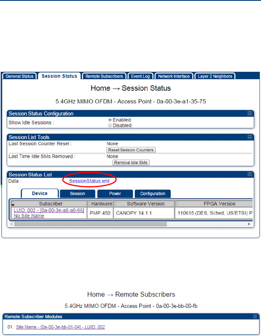
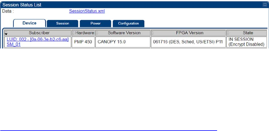
For example, to access one of the SMs, click
LUID: 002 – [0a-00-3e-37-b9-fd]
, as shown in Figure 147.
Figure 147
AP Session Status page
The
SessionStatus.xml
hyper link allows user to export all displayed SM data in Session Status table
into an xml file.
To access any one of the SMs, click 450 Platform Family - SM
hyperlink, as shown in Figure 148.
Figure 148
AP Remote Subscribers page
Chapter 7: Configuration Monitoring the Link
Page 7-196
Monitoring the Link
Link monitoring procedure
After configuring the link, either an operator in the network office or the SM/BHS INSTALLER user in the
field (if read access to the AP/BHM is available to the INSTALLER) must perform the following procedure.
Who is authorized and able to do this depends on local operator password policy, management VLAN
setup and operational practices.
To monitor the link for performance, follow these instructions:
Procedure 22
Monitoring the AP-SM link
1
Access the web interface of the AP/BHM
2
In the left-side menu of the AP/BHM interface, select
Home
.
3
Click the
Session Status
tab.
Figure 149
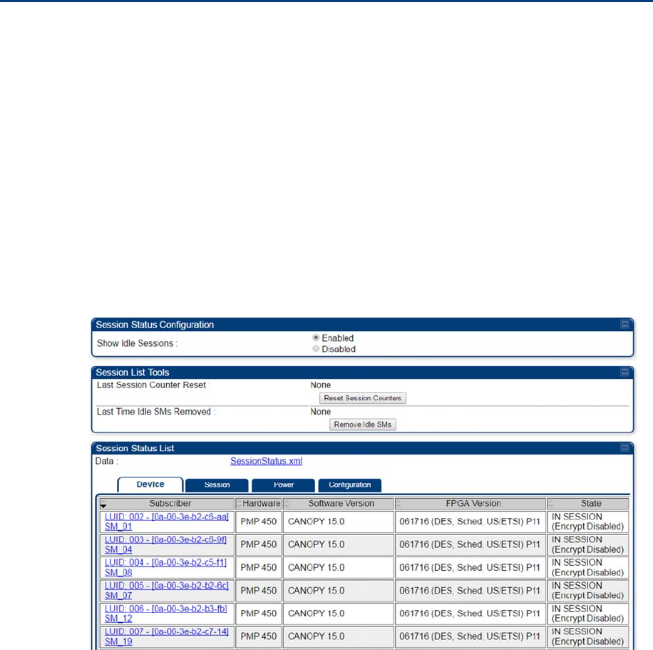
Session Status page
4
The
Device
tab of Session Status List display all displayed SMs – MAC address, PMP/PTP
Hardware, Software Version, FPGA Version and State
Chapter 7: Configuration Monitoring the Link
Page 7-197
5 Click Session Count tab of Session Status List to display values for Session Count, Reg
Count, and Re-Reg Count.
Session Count: This field displays how many sessions the SM/BHS has had with the
AP/BHM. Typically, this is the sum of Reg Count and Re-Reg Count. However, the result
of internal calculation may display here as a value that slightly differs from the sum.
Reg Count: When a SM/BHS makes a Registration Request, the AP/BHM checks its
local session database to see whether it was registered earlier. If the AP/BHM concludes
that the SM/BHS is not currently in session database and it is valid Registration Request,
then the request increments the value of this field.
Re-Reg Count: When a SM/BHS makes a Registration Request, the AP/BHM checks its
local session database to see whether it was registered earlier. If the AP/BHM concludes
that the SM/BHS is currently in session database, then the request increments the value
of this field.
Typically, a Re-Reg is the case where both
o SM/BHS attempts to reregister for having lost communication with the AP/BHM.
o AP/BHM has not yet observed the link to the SM/BHS as being down.
See Session tab on page 9-21
6 Click Power tab of Session Status list to display Downlink Rate, AP Rx Power (dBm), Signal
Strength Radio (dB) for Uplink and Signal to Noise Radio (dB) for Uplink.
See Power tab on page 9-23
7 Click Configuration tab of Session Status list to get QoS configuration details:
Sustained Data Rate (kbps)
Burst Allocation (kbit)
Max Burst Rate (kbit)
Low Priority CIR (kbps)
See
Configuration tab on page 9-25
8 Briefly monitor these values, occasionally refreshing this page by clicking another tab and
then the Session Status tab again.
9 If these values are low (for example, 1, 1, and 0, respectively, meaning that the SM/BHS
registered and started a stable session once) and are not changing:
Consider the installation successful.
Monitor these values from the network office over the next several hours and days.
If these values are greater than 1, 1, and 0, or they increase while you are monitoring them,
troubleshoot the link. (For example, Use Receive Power Level for aiming and then use Link
Tests to confirm alignment).
Refer Viewing Session Status on page 9-20 for more details.
Chapter 7: Configuration Monitoring the Link
Page 7-198
Exporting Session Status page of AP/BHM
The SessionStatus.xml hyper link allows user to export all displayed SMs or BHS data in Session Status
table into an xml file.
Figure 150
Exporting Session Status page of PMP 450m AP
In case of PMP, if the session status page does not list any SM, the SessionStatus.xml will still be visible
but the file would be empty. The file will contain data from all of the 5 different tables.
Export from command line
The scripts users can also get this file from command line, you have to authenticate successfully in order
to download the file.
Wget
http://169.254.1.1/SessionStatus.xml?CanopyUsername=test&CanopyPassword=test

Chapter 7: Configuration Configuring quality of service
Page 7-199
Configuring quality of service
Maximum Information Rate (MIR) Parameters
Point-to-multipoint links use the following MIR parameters for bandwidth management:
Sustained Uplink Data Rate (kbps)
Uplink Burst Allocation (kb)
Sustained Downlink Data Rate (kbps)
Downlink Burst Allocation (kb)
Max Burst Downlink Data Rate (kbps)
Max Burst Uplink Data Rate (kbps)
Set each of these parameters per AP or per SM independently.
Note
You can refer below whitepaper for 450 Platform Family Max Burst MIR:
http://www.cambiumnetworks.com/resources/pmp-450-maxburst/
Token Bucket Algorithm
The software uses a token bucket algorithm that has the following features:
Stores credits (tokens) for the SM to spend on bandwidth for reception or transmission.
Drains tokens during reception or transmission.
Refills with tokens at the sustained rate set by the network operator.
For each token, the SM can send toward the network in the uplink (or the AP can send toward the SM in
the downlink) an equivalent number of kilobits. Two buckets determine the permitted throughput: one in
the SM for uplink and one in the AP for downlink.
The applicable set of Uplink Burst Allocation and Downlink Burst Allocation parameters determine
the number of tokens that can fill each bucket. When the SM transmits (or the AP transmits) a packet, the
equivalent number of tokens is removed from the uplink (or downlink) bucket.
Except when full, the bucket is continuously being refilled with tokens at rates that the applicable set of
Sustained Uplink Data Rate and Sustained Downlink Data Rate parameters specify. The bucket often
drains at a rate that is much faster than the sustained data rate but can refill at only the sustained data
rate. Thus, the effects of the allocation and rate parameters on packet delay are as follows:
The burst allocation affects how many kilobits are processed before packet delay is imposed.
The sustained data rate affects the packet delay that is imposed.
Chapter 7: Configuration Configuring quality of service
Page 7-200
MIR Data Entry Checking
Uplink and downlink MIR is enforced as shown in Figure 151.
Note
In these figures, entry refers to the setting in the data rate parameter, not the burst allocation
parameter.
Figure 151 Uplink and downlink rate caps adjusted to apply aggregate cap
For example, in the SM, if you set the Sustained Uplink Data Rate parameter to 2,000 kbps and the
Sustained Downlink Data Rate parameter to 10,000 kbps, then the uplink and downlink MIR that is
enforced for the SM can be calculated as shown in Figure 152.
Figure 152 Uplink and downlink rate cap adjustment example
`
In this example case, the derived 1,167-kbps uplink and 5,833-kbps downlink MIR sum to the fixed 7,000-
kbps aggregate cap of the SM.
Committed Information Rate (CIR)
The Committed Information Rate (CIR) capability feature enables the service provider to guarantee to any
subscriber that bandwidth will never decrease to below a specified minimum unless CIR is
oversubscribed or RF conditions are degraded. CIR is oversubscribed when there is not enough available
bandwidth to support CIR configuration for all subscribers. In this condition, SMs which are configured
with a nonzero CIR will all operate at the maximum data rate supported by the link (subject to Maximum
Information Rate and Burst Rate/Allocations). SMs which are configured with a CIR of 0 kbps will not
transmit until CIR-configured SMs have completed transmission. CIR may be configured independently
for high priority traffic and for low priority traffic.
CIR parameters may be configured in the following ways:
Web-based management GUI
SNMP
Authentication Server (RADIUS) - when an SM successfully registers and authenticates, CIR
information is retrieved from the RADIUS server.
uplink cap enforced =
uplink entry x aggregate cap
f
or the
SM
u
p
link entr
y
+ downlink entr
y
downlink cap enforced =
downlink entry x aggregate cap
f
or the
SM
u
p
link entr
y
+ downlink entr
y
uplink cap enforced =
2,000 kbps x 7,000 kbps
2,000 kb
p
s + 10,000 kb
p
s
= 1,167 kbp
s
downlink cap enforced =
10,000 kbps x 7,000 kbps
2,000 kb
p
s + 10,000 kb
p
s
= 5,833 kbp
s
Chapter 7: Configuration Configuring quality of service
Page 7-201
Active CIR configuration can be verified via the AP’s Home > Session Status page.
Bandwidth from the SM Perspective
In the SM, normal web browsing, e-mail, small file transfers and short streaming video are rarely rate
limited with practical bandwidth management (QoS) settings. When the SM processes large downloads
such as software upgrades and long streaming video or a series of medium-size downloads, the bucket
rapidly drains, the burst limit is reached, and some packets are delayed. The subscriber experience is
more affected in cases where the traffic is more latency sensitive.
Interaction of Burst Allocation and Sustained Data
Rate Settings
If the Burst Allocation is set to 1200 kb and the Sustained Data Rate is set to 128 kbps, a data burst of
1000 kb is transmitted at full speed because the Burst Allocation is set high enough. After the burst, the
bucket experiences a significant refill at the Sustained Data Rate. This configuration uses the advantage
of the settable Burst Allocation.
If both the Burst Allocation and the Sustained Data Rate are set to 128 kb, a burst is limited to the Burst
Allocation value. This configuration does not take advantage of the settable Burst Allocation.
If the Burst Allocation is set to 128 kb and the Sustained Data Rate is set to 256 kbps, the actual rate is
the burst allocation (but in kbps). As above, this configuration does not take advantage of the settable
Burst Allocation.
High-priority Bandwidth
To support low-latency traffic such as VoIP (Voice over IP) or video, the system implements a high-priority
channel. This channel does not affect the inherent latencies in the system but allows high-priority traffic to
be immediately served. The high-priority pipe separates low-latency traffic from traffic that is latency
tolerant, such as standard web traffic and file downloads.
The number of channels available on the AP is reduced by the number of SMs configured for the high-
priority channel (each SM operating with high-priority enabled uses two channels (virtual circuits) instead
of one).
A module prioritizes traffic by
reading the Low Latency bit (Bit 3) in the Ipv4 Type of Service (ToS) byte in a received packet. Bit 3 is
set by a device outside the system.
reading the 802.1p field of the 802.1Q header in a received packet, where VLAN is enabled on the
module.
comparing the 6-bit Differentiated Services Code Point (DSCP) field in the ToS byte of a received
packet to a corresponding value in the Diffserv tab of the Configuration page of the module. A packet
contains no flag that indicates whether the encoding is for the Low Latency bit or the DSCP field. For
this reason, you must ensure that all elements in your trusted domain, including routers and
endpoints, set and read the ToS byte with the same scheme.
Modules monitor ToS bytes with DSCP fields, but with the following differences:
The 6-bit length of the field allows it to specify one of 64 service differentiations.
These correlate to 64 individual (CodePoint) parameters in the Diffserv tab of the Configuration
page.

Chapter 7: Configuration Configuring quality of service
Page 7-202
Per RFC 2474, 3 of these 64 are preset and cannot be changed. (See
http://www.faqs.org/rfcs/rfc1902.html.)
For any or all of the remaining 61 CodePoint parameters, you can specify a value of
o 0 through 3 for low-priority handling.
o 4 through 7 for high-priority handling.
Note
Ensure that your Differentiated Services domain boundary nodes mark any entering packet,
as needed, so that it specifies the appropriate Code Point for that traffic and domain. This
prevents theft of service level.
An example of the Diffserv page in the Configuration menu and parameter descriptions are provided
under DiffServ attributes – AP/BHM on page 7-60. This tab and its rules are identical from module type to
module type. However, any of the 61 configurable Code Points can be set to a different value from
module to module, thus defining unique per-hop behavior for some traffic.
This tab in the AP sets the priorities for the various packets in the downstream (sent from the public
network). This tab in the SM sets the priorities for the various packets in the upstream (sent to the public
network).
Typically, some SMs attach to older devices that use the ToS byte as originally formatted, and others to
newer devices that use the DSCP field. The default values in the Diffserv page allow your modules to
prioritize traffic from the older devices roughly the same as they traditionally have. However, these default
values may result in more high-priority traffic as DSCP fields from the newer devices are read and
handled. So, after making changes in the Diffserv page, carefully monitor the high-priority channel for
high packet rates
in SMs that you have identified as those to initially set and watch.
across your network when you have broadly implemented Code Point values, such as via SNMP.
Chapter 7: Configuration Configuring quality of service
Page 7-203
Traffic Scheduling
The characteristics of traffic scheduling in a sector are summarized in Table 173.
Table 173 Characteristics of traffic scheduling
Category Factor Treatment
Throughput Aggregate throughput, less additional
overhead 132 Mbps
Latency Number of frames required for the scheduling
process 1
Round-trip latency ≈ 6 ms
AP broadcast the download schedule No
High-priority
Channel
Allocation for uplink high-priority traffic on
amount of high-priority traffic
Dynamic, based on amount of high-
priority traffic
Allocation for downlink high-priority traffic on
amount of high-priority traffic
Dynamic, based on amount of high-
priority traffic
Order of transmission
CIR high-priority
CIR low-priority
Other high-priority
Other low-priority
Caution
Power requirements affect the recommended maximums for power cord length feeding the
CMM4. See the dedicated user guide that supports the CMM that you are deploying.
Packets that have a priority of 4 to 7 in either the DSCP or a VLAN 802.1p tag are automatically sent on
the high-priority channel, but only where the high-priority channel is enabled.
Chapter 7: Configuration Configuring quality of service
Page 7-204
Setting the Configuration Source
The AP includes a Configuration Source parameter, which sets where SMs that register to the AP are
controlled for MIR, CIR, VLAN, and the high-priority channel as follows. The Configuration Source
parameter affects the source of:
all MIR settings:
o Sustained Uplink Data Rate
o Uplink Burst Allocation
o Max Burst Uplink Data Rate
o Sustained Downlink Data Rate
o Downlink Burst Allocation
o Max Burst Downlink Data Rate
all CIR settings:
o Low Priority Uplink CIR
o Low Priority Downlink CIR
o Hi Priority Uplink CIR
o Hi Priority Downlink CIR
all SM VLAN settings
o Dynamic Learning
o Allow Only Tagged Frames
o VLAN Aging Timeout
o Untagged Ingress VID
o Management VID
o VLAN Membership
the Hi Priority Channel setting
Table 174 Recommended combined settings for typical operations
Most operators who
use…
must set this
parameter…
in this web page/tab… in the AP to…
no authentication
server
Authentication Mode Configuration/ Security Disabled
Configuration Source Configuration/ General SM
Wireless Manager
(Authentication Server)
Authentication Mode Configuration/ Security Authentication Server
Configuration Source Configuration/ General Authentication Server
RADIUS AAA server
Authentication Mode Configuration/ Security RADIUS AAA
Configuration Source Configuration/ General Authentication Server
Table 175 Where feature values are obtained for a SM with authentication required
Values are obtained from
Chapter 7: Configuration Configuring quality of service
Page 7-205
Configuration
Source Setting
in the AP
MIR Values VLAN Values High Priority Channel
State
Authentication
Server Authentication Server Authentication Server Authentication Server
SM SM SM SM
Authentication
Server+SM Authentication Server Authentication Server,
then SM
Authentication Server,
then SM
Note
HPC represents the Hi Priority Channel (enable or disable).
Where Authentication Server, then SM is the indication, parameters for which Authentication
Server does not send values are obtained from the SM. This is the case where the
Authentication Server is operating on an Authentication Server release that did not support
the feature. This is also the case where the feature enable/disable flag in Authentication
Server is set to disabled. The values are those previously set or, if none ever were, then the
default values.
Where Authentication Server is the indication, values in the SM are disregarded.
Where SM is the indication, values that Authentication Server sends for the SM are
disregarded.
For any SM whose Authentication Mode parameter is not set to ‘Authentication Required’, the listed
settings are derived as shown in Table 176.
Table 176 MIR, VLAN, HPC, and CIR Configuration Sources, Authentication Disabled
Configuration
Source Setting
in the AP
Values are obtained from
MIR Values VLAN Values High Priority
Channel State
CIR Values
Authentication Server AP AP AP AP
SM SM SM SM SM
Authentication
Server+SM
SM SM SM SM
Chapter 7: Configuration Configuring quality of service
Page 7-206
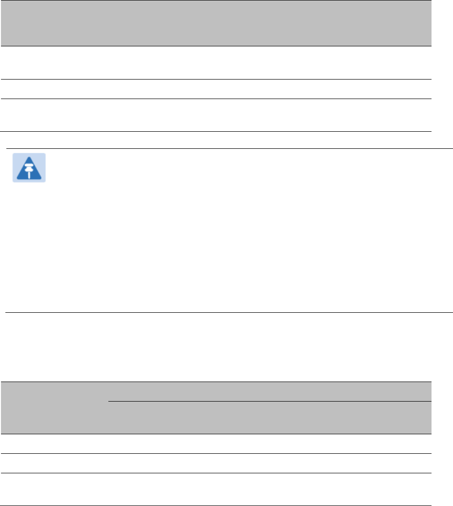
Configuring Quality of Service (QoS)
Quality of Service (QoS) page of AP
The QoS page of AP is explained in Table 177.
Table 177
QoS page attributes - AP
Attribute Meaning
Max Burst Uplink Data
Rate
These parameters allow operators to specify the data rate at which a SM is
allowed to transmit (until burst allocation limit is reached) before being
recharged at the
Sustained Uplink Data Rate
with credits to transit more.
When set to 0 (default), the burst rate is unlimited.
Sustained Uplink Data
Rate
Specify the rate that each SM registered to this AP is replenished with credits
for transmission. This default imposes no restriction on the uplink. See
Maximum Information Rate (MIR) Parameters on page 7-198
Interaction of Burst Allocation and Sustained Data Rate Settings on page
7-200
Configuration Source on page 7-69
Uplink Burst Allocation
Specify the maximum amount of data to allow each SM to transmit before
being recharged at the
Sustained Uplink Data Rate
with credits to transmit
more. See Maximum Information Rate (MIR) Parameters on page 7-198
Interaction of Burst Allocation and Sustained Data Rate Settings on page
7-200
Configuration Source on page 7-69
Max Burst Downlink
Data Rate
These parameters allow operators to specify the data rate at which a SM is
allowed to transmit (until burst allocation limit is reached) before being
recharged at the
Sustained Downlink Data Rate
with credits to transit more.
When set to 0 (default), the burst rate is unlimited.

Chapter 7: Configuration Configuring quality of service
Page 7-207
Sustained Downlink
Data Rate
Specify the rate at which the AP is replenished with credits (tokens) for
transmission to each of the SMs in its sector. This default imposes no
restriction on the uplink. See Maximum Information Rate (MIR) Parameters
on page 7-198
Interaction of Burst Allocation and Sustained Data Rate Settings on page
7-200
Configuration Source on page 7-69
Downlink Burst
Allocation
Specify the maximum amount of data to allow the AP to transmit to any
registered SM before the AP is replenished with transmission credits at the
Sustained Downlink Data Rate. See
Maximum Information Rate (MIR) Parameters on page 7-198
Interaction of Burst Allocation and Sustained Data Rate Settings on page
7-200
Configuration Source on page 7-69
Broadcast Downlink
CIR
Broadcast Downlink CIR (Committed Information Rate, a minimum) supports
system designs where downlink broadcast is desired to have higher priority
than other traffic. For many other system designs, especially typical internet
access networks, leave the Broadcast Downlink CIR at the default.
Broadcast Downlink CIR is closely related to the Broadcast Repeat Count
parameter, which is settable in the Radio tab of the Configuration page in the
AP: when the Broadcast Repeat Count is changed, the total of available
bandwidth is also changed, since packets are being sent one, two, or three
times, according to the setting in the Broadcast Repeat Count parameter.
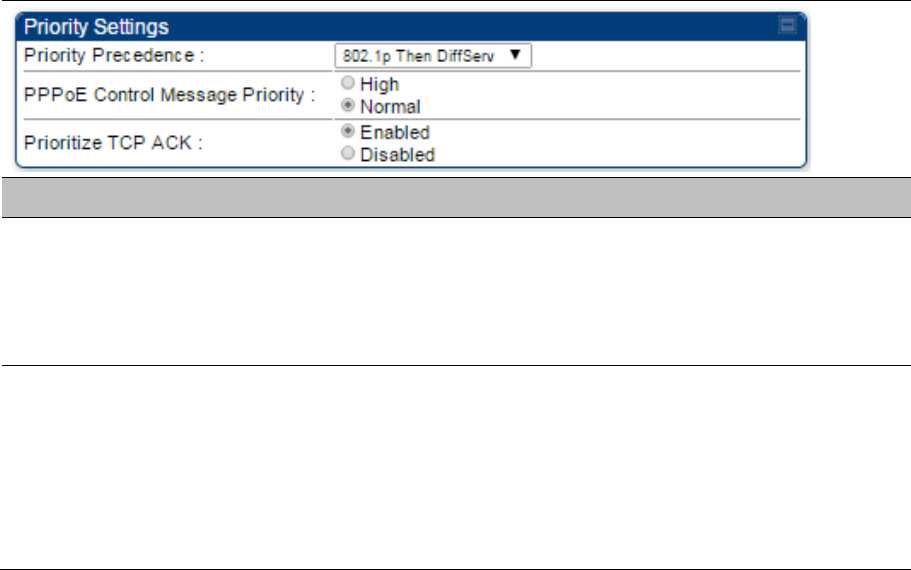
Priority Precedence Allows operator to decide if 802.1p or DiffServ priority bits must be used first
when making priority decisions.
PPPoE Control
Message Priority
Operators may configure the SM to utilize the high priority channel for PPPoE
control messages. Configuring the SM in this fashion can benefit the
continuity of PPPoE connections when there are issues with PPPoE sessions
being dropped in the network. This prioritization may be configured in the
DiffServ tab in the Configuration menu of the SM.
Prioritize TCP ACK To reduce the likelihood of TCP acknowledgement packets being dropped,
set this parameter to Enabled. This can improve throughput that the end user
perceives during transient periods of congestion on the link that is carrying
acknowledgements.
Quality of Service (QoS) page of SM
The QoS page of SM is explained in Table 178.
Chapter 7: Configuration Configuring quality of service
Page 7-208
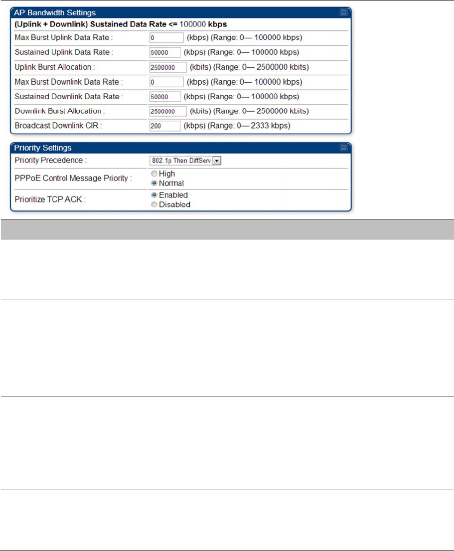
Table 178 QoS page attributes - SM
Attribute Meaning
Sustained Uplink Data
Rate
Specify the rate that this SM is replenished with credits for transmission. This
default imposes no restriction on the uplink. See Maximum Information Rate
(MIR) Parameters on page 7-198
Interaction of Burst Allocation and Sustained Data Rate Settings on page
7-200
Configuration Source on page 7-69
Sustained Downlink
Data Rate
Specify the rate at which the AP is replenished with credits (tokens) for
transmission to this SM. This default imposes no restriction on the uplink. See
Maximum Information Rate (MIR) Parameters on Page 7-198
Interaction of Burst Allocation and Sustained Data Rate Settings on page
7-200
Configuration Source on page 7-69
Uplink Burst Allocation
Specify the maximum amount of data to allow this SM to transmit before
being recharged at the Sustained Uplink Data Rate with credits to transmit
more. See Maximum Information Rate (MIR) Parameters on page 7-198
Interaction of Burst Allocation and Sustained Data Rate Settings on page
7-200
Configuration Source on page 7-69

Chapter 7: Configuration Configuring quality of service
Page 7-209
Downlink Burst
Allocation
Specify the maximum amount of data to allow the AP to transmit to this SM
before the AP is replenished at the Sustained Downlink Data Rate with
transmission credits. See Maximum Information Rate (MIR) Parameters on
page 7-198
Interaction of Burst Allocation and Sustained Data Rate Settings on page
7-200
Configuration Source on page 7-69
Max Burst Uplink Data
Rate
These parameters allow operators to specify the data rate at which a SM is
allowed to transmit (until burst allocation limit is reached) before being
recharged at the Sustained Uplink Data Rate with credits to transit more.
When set to 0 (default), the burst rate is unlimited.
Max Burst Downlink
Data Rate
These parameters allow operators to specify the data rate at which a SM is
allowed to transmit (until burst allocation limit is reached) before being
recharged at the Sustained Downlink Data Rate with credits to transit more.
When set to 0 (default), the burst rate is unlimited.
Enable Broadcast /
Multicast Data Rate
This parameter allows the operator to specify if Broadcast and Multicast data
is rate-limited. This data rate can be entered in Kbps or PPS (Packets Per
Second).
Broadcast / Multicast
Data Rate
This parameter allows the operator to specify a data rate at which Broadcast
and Multicast traffic is sent via the radio link.
Low Priority Uplink
CIR
This field indicates the minimum rate at which low priority traffic is sent over
the uplink (unless CIR is oversubscribed or RF link quality is degraded).
Committed Information Rate (CIR) on page 7-199
Setting the Configuration Source on page 7-203
Low Priority Downlink
CIR
This field indicates the minimum rate at which low priority traffic is sent over
the downlink (unless CIR is oversubscribed or RF link quality is degraded).
Committed Information Rate (CIR) on page 7-199
Setting the Configuration Source on page 7-203
Hi Priority Channel
See
High-priority Bandwidth on page 7-200
Configuration Source on page 7-69
Hi Priority Uplink CIR This field indicates the minimum rate at which high priority traffic is sent over
the uplink (unless CIR is oversubscribed or RF link quality is degraded).
Committed Information Rate (CIR) on page 7-199
Setting the Configuration Source on page 7-203
Hi Priority Downlink
CIR
This field indicates the minimum rate at which high priority traffic is sent over
the downlink (unless CIR is oversubscribed or RF link quality is degraded).
Committed Information Rate (CIR) on page 7-199
Setting the Configuration Source on page 7-203
Chapter 7: Configuration Configuring quality of service
Page 7-210
Priority Precedence Allows operator to decide if 802.1p or DiffServ priority bits must be used first
when making priority decisions.
PPPoE Control
Message Priority
Operators may configure the SM to utilize the high priority channel for PPPoE
control messages. Configuring the SM in this fashion can benefit the
continuity of PPPoE connections when there are issues with PPPoE sessions
being dropped in the network. This prioritization may be configured in the
DiffServ tab in the Configuration menu of the SM.
Prioritize TCP ACK To reduce the likelihood of TCP acknowledgement packets being dropped,
set this parameter to Enabled. This can improve throughput that the end user
perceives during transient periods of congestion on the link that is carrying
acknowledgements. This parameter, when enabled, can be particularly useful
when running bi-direction FTP sessions over the link. If a link is primarily used
for video surveillance, it is recommended to configure this parameter to
Disabled.
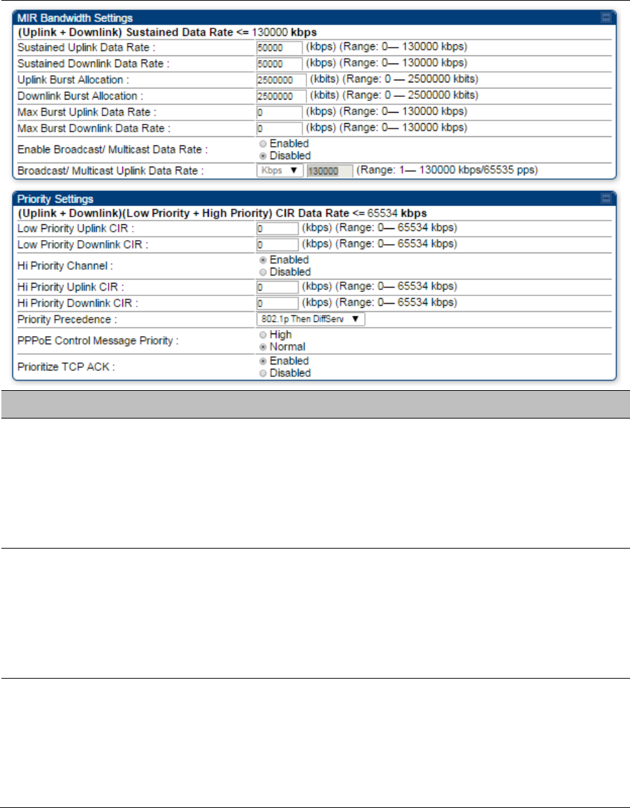
Quality of Service (QoS) page of BHM
The QoS page of BHM is explained in Table 179.
Table 179 QoS page attributes - BHM
Attribute Meaning
PPPoE Control
Message Priority
Operators may configure the BHM to utilize the high priority channel for
PPPoE control messages. Configuring the BHM in this fashion can benefit the
continuity of PPPoE connections when there are issues with PPPoE sessions
being dropped in the network. This prioritization may be configured in the
DiffServ tab in the Configuration menu of the BHS.
Prioritize TCP ACK To reduce the likelihood of TCP acknowledgement packets being dropped,
set this parameter to Enabled. This can improve throughput that the end user
perceives during transient periods of congestion on the link that is carrying
acknowledgements. This parameter, when enabled, can be particularly useful
when running bi-direction FTP sessions over the link. If a link is primarily used
for video surveillance, it is recommended to configure this parameter to
Disabled.
Quality of Service (QoS) page of BHS
The QoS page of BHS is explained in Table 180.
Chapter 7: Configuration Configuring quality of service
Page 7-211
Table 180 QoS page attributes - BHS
Attribute Meaning
PPPoE Control
Message Priority
Operators may configure the BHS to utilize the high priority channel for
PPPoE control messages. Configuring the BHS in this fashion can benefit the
continuity of PPPoE connections when there are issues with PPPoE sessions
being dropped in the network. This prioritization may be configured in the
DiffServ tab in the Configuration menu of the BHS.
Prioritize TCP ACK To reduce the likelihood of TCP acknowledgement packets being dropped,
set this parameter to Enabled. This can improve throughput that the end user
perceives during transient periods of congestion on the link that is carrying
acknowledgements. This parameter, when enabled, can be particularly useful
when running bi-direction FTP sessions over the link. If a link is primarily used
for video surveillance, it is recommended to configure this parameter to
Disabled.
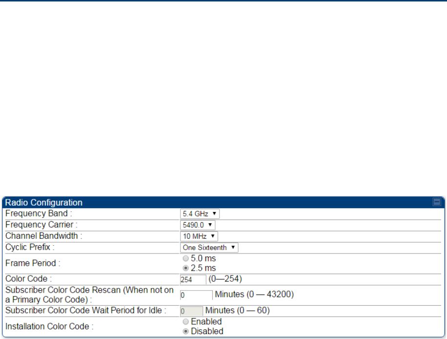
Chapter 7: Configuration Installation Color Code
Page 7-212
Installation Color Code
With this feature enabled on the AP and SM, operators may install and remotely configure SMs without
having to configure matching color codes between the modules. While the SM is accessible for
configuration from above the AP (for remote provisioning) and below the SM (for local site provisioning),
no user data is passed over the radio link. When using the Installation Color Code feature, ensure that the
SM is configured with the factory default Color Code configuration (Color Code 1 is “0”, Color Code 2-10
set to “0” and “Disable”). The status of the Installation Color Code can be viewed on the AP Eval web GUI
page, and when the SM is registered using the Installation Color Code the message “SM is registered via
ICC – Bridging Disabled!” is displayed in red on every SM GUI page. The Installation Color Code
parameter is configurable without a radio reboot for both the AP and SM. If an SM is registered via
Installation Color Code and the feature is then disabled, operators will need to reboot the SM or force it to
reregister (i.e. using the Rescan APs functionality on the AP Eval page).
Figure 153 Installation Color Code of AP

Chapter 7: Configuration Zero Touch Configuration Using DHCP Option 66
Page 7-213
Zero Touch Configuration Using DHCP
Option 66
This feature allows an SM to get its configuration via DHCP option 66. This can be used for the initial
configuration of an SM as well as managing the configuration of SMs on an ongoing basis. Here is how it
works in brief:
When the SM boots up, if it is set to use DHCP client, it will send out a DHCP Discover packet which
includes a request for DHCP Option 66.
In case of a brand new SM out of the box, the DHCP Discover packet is sent out if the SM connects
to an AP using Installation Color Code (ICC), even though DHCP client is not enabled in factory
default config.
An appropriately configured DHCP server will respond with a DHCP Offer and include a URL in
response to the Option 66 request. The URL should point to the configuration file.
The device will download the configuration file and apply it. The device will reboot automatically if
needed. (Note: this requires “rebootIfRequired” flag to be added to the config file. See Creating a
Golden config file on page 7-213.
Configuration Steps
Procedure 23 Zero Touch Configuration steps
1 Create the golden config file(s)
2 Host it on an TFTP/FTP/HTTP/HTTPS server
3 Configure the DHCP server to return the URL of the golden config file in option 66
When the SM boots up, it will get the URL for the golden config from the DHCP server via option 66,
download it and apply it.
If all the SMs are configured exactly the same, then you can create just new golden config file that can be
used with all SMs.
If the SMs are not configured the same, see if it is possible to group the SMs such that SMs with the
same configuration are served by the same DHCP pool. User can then create multiple golden config files
and configure the DHCP server to use the appropriate config file for each pool.
User can also create one config file per SM. This provides the most flexibility, but is practical only if you
have a software tool/script to generate the config files for each MAC address. The files should be named
<mac>.cfg where <mac> is the MAC address of the SM, and stored in the same directory on the file
server. The DHCP server should be configured to return the directory name ending with a ‘/’ in option 66.
The SM will automatically add “<mac>.cfg” to the path and get its config file.

Chapter 7: Configuration Zero Touch Configuration Using DHCP Option 66
Page 7-214
If some configuration is unique per SM, but rest of the configuration is common, the SMs can be staged
with the unique part, and use option 66 to manage the common part. For example, if each SM needs to
have its coordinates set, don’t include the coordinates in the golden config file. Instead, configure the
coordinates for each SM manually. Manage the rest of the configuration using DHCP option 66.
Creating a Golden config file
The easiest way to create the golden config file is to configure an SM, export its configuration and edit it.
To export the configuration file from the GUI of the SM, go to “Configuration > Unit Settings” tab, go to the
“Download Configuration File” section and click on the “<mac>.cfg” link. This will give you a text file in
JSON format. You can edit this file in a text editor but it’s easier to use a JSON editor like
https://www.jsoneditoronline.org/.
Strip down the config file to remove sections and entries that don’t care about, and keep only the items
that require changes. If there are many required changes, it can easily get confusing. To identify the exact
items changes, first reset the SM to factory default, export the config file, make the necessary changes,
export a second config file, then use a tool like WinMerge (http://winmerge.org/) to identify the
differences.
The config file contains the following informational entries at the top level.
“cfgUtcTimestamp”: “cfgUtcTimestamp”,
“swVersion”: “CANOPY 15.1 SM-AES”,
“cfgFileString”: “Canopy configuration file”,
“srcMacAddress”: “0a-00-3e-a2-c2-74”,
“deviceType”: “5.4/5.7GHz MIMO OFDM - Subscriber Module”,
“cfgFileVersion”: “1.0”
The “cfgUtcTimestamp”, “swVersion”, “srcMacAddress” and “deviceType” lines can be deleted. Do not
delete the “cfgFileString” and “cfgFileVersion” entries.
Next, create an object named “configFileParameters” at the top level. Under that, add a parameter called
“rebootIfRequired” and set it to true. This tells the SM to reboot automatically if a reboot is needed to
apply the new configuration.
A sample configuration file that has been edited for use via DHCP option 66 is given below.
{
“userParameters”: {
“smNetworkConfig”: {
“networkAccess”: 1
},
“location”: {
“siteName”: “Test site”
},
“smRadioConfig”: {
“frequencyScanList”: [
Chapter 7: Configuration Zero Touch Configuration Using DHCP Option 66
Page 7-215
5475000,
5480000
],
“colorCodeList”: [
{
“colorCode”: 42,
“priority”: 1
}
]
},
“networkConfig”: {
“lanDhcpState”: 1
}
},
“cfgFileVersion”: “1.0”,
“cfgFileString”: “Canopy configuration file”,
“configFileParameters”: {
“rebootIfRequired”: true
}
}
When configuration is imported, only the items that exist in the configuration file are modified. Parameters
that are not in the imported file are not changed. If user wish to revert those settings to their factory
default values, please add a “setToDefaults” item under “configFileParameters” section with a value of
true.
“cfgFileVersion”: “1.0”,
“cfgFileString”: “Canopy configuration file”,
“configFileParameters”: {
“rebootIfRequired”: true,
“setToDefaults”: true
}
In case, the SM needs to fetch the configuration file on each boot up even when not connecting to AP via
ICC, set “Network Accessibility” to “Public” and “DHCP State” to “Enabled” in the “Configuration > IP”
page before exporting the configuration.
Hosting the config file
Copy the golden configuration file to an FTP, TFTP, HTTP or HTTPS server. This location can be
password protected; you just have to include the user name and password in the URL.
DHCP server configuration
Configure DHCP server to return the full URL to the golden config file as the value of DHCP option 66.
The following example explains how to make the change for Windows Server 2008. Adapt it to your
specific DHCP server.
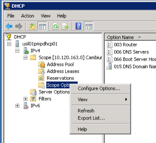
Chapter 7: Configuration Zero Touch Configuration Using DHCP Option 66
Page 7-216
Procedure 24 DHCP server configuration
1 Click “Start > Administrative Tools > DHCP”
2 If you have multiple “Scopes” defined, identify the correct “Scope” that will serve IP
addresses for the SMs
3 Right click on “Scope Option” under the correct “Scope” and select “Configure Options”
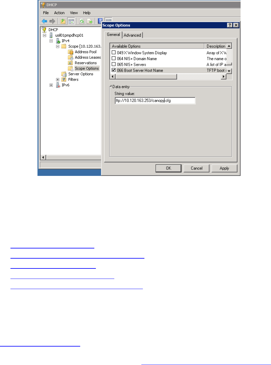
Chapter 7: Configuration Zero Touch Configuration Using DHCP Option 66
Page 7-217
4 In the “Scope Options” dialog, scroll down to “066 Boot Server Host Name”, select the
checkbox and enter the full URL to the golden config file as the “String value”. Then click
“OK”.
5 In the DHCP snap-in window, right click and “Refresh” to see the DHCP option 66 in the list
of DHCP options
Supported URL Formats
FTP, TFTP, HTTP and HTTPS URLs are supported. Some examples are given below.
ftp://10.120.163.253/canopy.cfg
ftp://admin:admin123@10.120.163.253/canopy.cfg (login as admin with password admin123)
tftp://10.120.163.253/canopy.cfg
http://10.120.163.253/golden-config.cfg
https://10.120.163.253/smconfig/golden-config.cfg
User can also specify the URL pointing to a directory and not a specific file. Terminate the URL with a ‘/’
to indicate that it is a directory and not a file. Use this format when each SM has its own individual config
file. The directory should contain files named “<mac>.cfg”, one for each SM.
For example:
ftp://10.120.163.253/smconfig/
In this case, the SM will append “<mac>.cfg” to the path and try to get that file. For example, if the SM’s
MAC address is 0a-00-3e-a2-c2-74, it will request for ftp://10.120.163.253/smconfig/0a003ea2c274.cfg.
This mechanism can be used to serve individual config file for each SM.
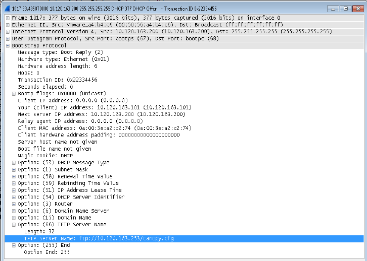
Chapter 7: Configuration Zero Touch Configuration Using DHCP Option 66
Page 7-218
Troubleshooting
1 Ensure that the___14 SM is running 13.3 or newer version of software.
2 If the SM has factory default config, confirm ICC is enabled on the AP, so the SM can
connect to it.
3 If the SM is connecting to the AP using a color code other than ICC, make sure the SM has
“Network Accessibility” set to “Public” and “DHCP State” set to “Enabled” in the
“Configuration > IP” page.
4 Make sure the golden config file does not turn off “Network Accessibility” or “DHCP State”. If
it does, the SM will no longer request the config file when it is rebooted.
5 Check the event log of the SM to see the status of the configuration file import including any
errors that prevented it from importing the file.
6 Capture the DHCP Offer packet from the DHCP server to the SM and verify that Option 66
has the expected URL.
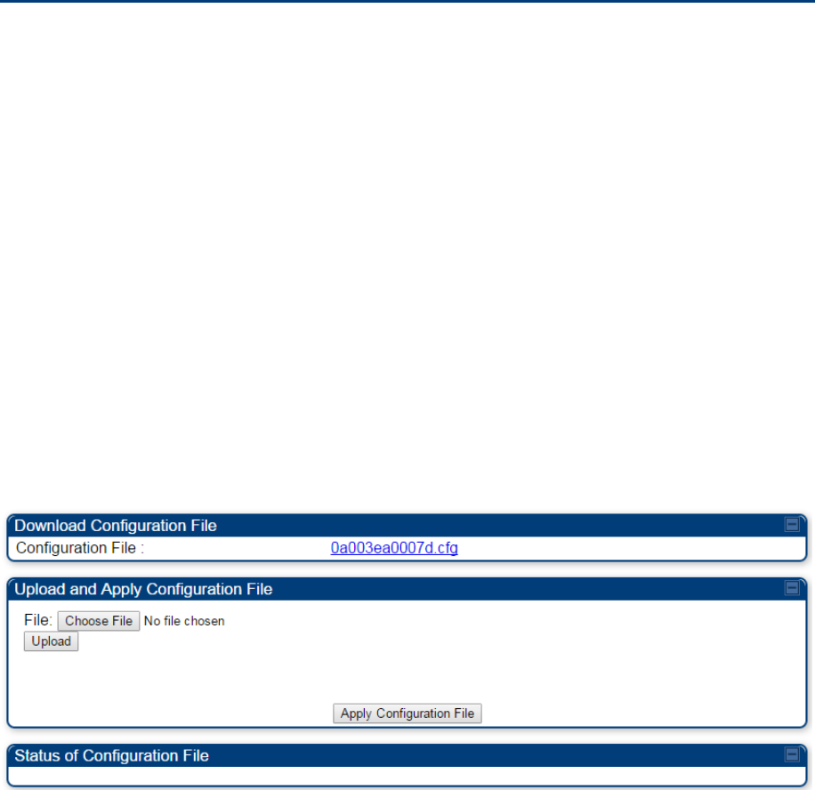
Chapter 7: Configuration Configuring Radio via config file
Page 7-219
Configuring Radio via config file
The 450 Platform Family supports export and import of a configuration file from the AP or SM as a text
file. The configuration file is in JSON format.
To export or import the configuration file, the logged in user needs to be an ADMINISTRATOR and it
must not be a “read-only” account.
The exported configuration file contains the complete configuration including all the default values. To
keep a backup of the current configuration, the file can be saved as-is and imported later.
While importing a configuration file, it can be either imported the full configuration or a sparse
configuration containing only the items that need to be changed. If a sparse configuration file is imported,
only the items in the file will be imported. Other configuration will remain unchanged. There could also be
used a special flag in the configuration file to tell the device to apply the configuration starting from factory
default (Refer Special Headers for configuration file on page 7-219).
Import and Export of config file
The config file import and export is supported in Configuration > Unit Settings page. The procedure for
importing and exporting config file is explained below.
Figure 154 Configuration File upload and download page
The DHCP server configuration procedure is as follows:
Procedure 25 DHCP server configuration
1 Login to the GUI and go to Configuration > Unit Settings.
2 Under Download Configuration File tab, click on the “<mac>.cfg” link, where <mac> is the
MAC address of the device (for example, “01003ea2c274.cfg”).
3 Save the file to the local disk.
The below procedure is to be followed for Importing a config file
Procedure 26 Import the configuration from the GUI
1 Login to the GUI and go to Configuration → Unit Settings.
Chapter 7: Configuration Configuring Radio via config file
Page 7-220
2 Click on “Browse” button under “Upload and Apply Configuration File” tab and select the
configuration file from disk.
3 Click “Upload” followed by “Apply Configuration File” button click.
4 The “Status of Configuration File” section will show the results of the upload.
5 Review it to make sure there are no errors. Then click on “Reboot” to reboot with the
imported configuration
The special headers for config file is explained below:
Procedure 27 Special Headers for configuration file
1 A “configFileParameters” section can be added to the header to control the behavior of the
device when importing configuration.
2 The “setToDefaults” when set to “true” tell the device to reset to factory default configuration
and apply the configuration in the file on top of that. So any attribute not in the configuration
file will be set to its factory default value. By default, the configuration in the file is merged
with the existing configuration on the device.
The “rebootIfRequired” flag when set to “true” tell the device to reboot automatically if
needed to apply the configuration change. By default, the device will not reboot automatically.
{
“cfgFileString”: “Canopy configuration file”,
“cfgFileVersion”: “1.0”,
“configFileParameters”: {
“setToDefaults”:true,
“rebootIfRequired”:true,
}
}
Chapter 7: Configuration Configuring cnMaestroTM Connectivity
Page 7-221
Configuring cnMaestroTM Connectivity
450 Platform Family network can be onboarded, configured and managed using cnMaestro™ Cloud or
On Premises Server.
Onboarding
Onboarding can be done in one of several ways:
Using Cambium ID and Onboarding key
Using Manufacturer’s Serial Number (Only if it starts with an “M” and is 12 characters long)
On Premises Zero Touch onboarding of AP/SM using DHCP option 43 and 15
PMP SM Zero touch onboarding to the cnMaestro server where PMP AP is onboarded.
To configure the PMP devices, enable Remote Management under Configuration->cnMaestro as shown
in Table 181.
Table 181
Configuring cnMaestro
Attribute Meaning
Remote Management This field enables/disables remote management of 450 Platform Family
products.
cnMaestro URL This field allows to enter cnMaestro URL e.g.
https://cloud.cambiumnetworks.com
Or cnMaestro on premises URL
Connection Status This field indicates cnMaestro connectivity status.
Cambium ID This field allows to enter Cambium ID for onboarding 450 Platform devices.
Onboarding Key This field allows to enter Onboarding Key for onboarding.
AccountID This field indicates Account ID of the customer.
Device Agent Version This field shows device agent version.
Chapter 7: Configuration Configuring cnMaestroTM Connectivity
Page 7-222
Prerequisites for onboarding to cnMaestro™
Devices types must be PMP 450m Series, PMP/PTP 450 Series, PMP/PTP 450i/450b Series or PMP
430 Series SMs (interoperability mode only).
Minimum required software version of 14.2.1. Device software images can be downloaded from
http://support.cambiumnetworks.com or from the On Premises cnMaestro server by navigating to
Operate >Software Update->Manage Images. Select
Device type to display the available images and then click the download icon as shown in Figure 155.
Figure 155
Software Upgrade from cnMaestro™
IP connectivity between PMP Device and the cnMaestro server is established. Ensure Port 443 is
open in the firewall as this port is used for secure communication between the PMP device and the
cnMaestro server through web sockets. In addition, if the PMP device and cnMaestro™ server are on
different subnets, proper routes should be established for communication.
For PMP AP, a valid DNS setting is required so that the AP will be able to resolve the cnMaestro
URL. DNS settings can be verified by performing a DNS lookup under Tools->DNS Test on the AP as
shown in Figure 156.
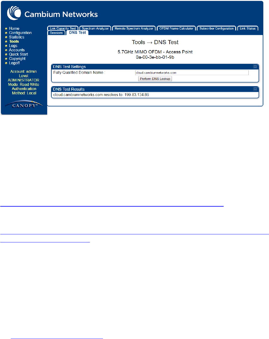
Chapter 7: Configuration Configuring cnMaestroTM Connectivity
Page 7-223
Figure 156 DNS Test for cnMaestro™ connectivity
If the SM is in Bridge mode, then LAN1 must have public 7-223equest7-223ility with a public IP
assigned and corresponding DNS setting.
If the SM is in NAT mode, then Remote Management should be enabled with the standalone
configuration option and DNS settings.
Knowledge Based articles for onboarding
For onboarding the devices to cloud server and troubleshooting the onboarding issues in cloud server
please see the following link:
http://community.cambiumnetworks.com/t5/cnMaestro/Device-On-boarding/td-p/51484
For onboarding the devices to on Premises server and configuring the DHCP server options for on
boarding please see the following link:
http://community.cambiumnetworks.com/t5/cnMaestro/Device-Onboarding-and-Linux-DHCP-Options-for-
cnMaestro-On/m-p/55187#U55187
Order of Device Onboarding
The device discovery order is as follows in On Permises cnMaestro™ Server. If any of the options is not
configured, the discovery method will fallback to the next option:
1. Static cnMaestro URL
2. Zero Touch token (on boarding of PMP SMs when the corresponding AP is on boarded)
3. DHCP Option 43
4. DHCP Option 15
5. https://cloud.cambiumnetworks.com
Chapter 7: Configuration Configuring cnMaestroTM Connectivity
Page 7-224
Device Agent Logs
For debugging any onboarding issues please check the device agent logs by navigating to Logs->Device
Agent Logs on the PMP device GUI as shown in Figure 157. In addition, a tech support dump can for the
PMP device can be obtained from cnMaestro™ by navigating to Monitor->Tools menu after selecting the
particular PMP device in the tree and clicking the tech support file icon. This can be send to Cambium
support for further troubleshooting.
Figure 157 Device Agent Logs
Monitoring Tools for PMP Devices on cnMaestro™
cnMaestro™ as of this release offers several debugging tools for PMP devices. Some examples are:
Pictorial view of network hierarchy
Device status
Tech support file
Throughput
Alarms
Reboot
Debug Logs
Network connectivity – ping and DNS lookup
Chapter 7: Configuration Configuring cnMaestroTM Connectivity
Page 7-225
Figure 158
Example cnMaestro™ screenshot
For more information on these tools please see
http://community.cambiumnetworks.com/t5/cnMaestro/How-to-use-the-cnMaestro-Tools-for-
Troubleshooting-Device-or/m-p/54503#U54503
Zero Touch on boarding of the PMP SMs when the
corresponding AP is on boarded
First a link should be established between the PMP AP and SM either by configuring manually or using
the ICC. Once the AP and SM link is established, the AP must be onboarded to cnMaestro™ using one of
several ways detailed above under the Onboarding section. Once the AP is onboarded to cnMaestro™
Cloud or On premises cnMaestro™server, the SMs under the AP will automatically onboard to
cnMaestro™ using a Zero touch token that is communicated between the AP and SMs. This is applicable
to existing SMs registered to the AP as well as new SMs registering to the AP for the first time. The SMs
appear on the onboarding queue of cnMaestro™ and the operator must “Approve” the devices in order to
manage them.
The following operations for PMP Devices are available on
cnMaestro™
Monitor the device details in the Dashboard page by navigating to the
Monitor >Dashboard
menu
and selecting the PMP AP/SM in the tree.
Monitor notifications related to the PMP AP/SM by navigating to the
Monitor >Notifications
Menu
and selecting the PMP AP/SM in the tree.
Monitor device statistics on the statistics page by navigating to the
Monitor >Statistics
menu and
selecting the PMP AP/SM in the tree, then selecting the PMP AP or PMP SM in the Device type
dropdown.
Monitor Performance graphs related to the PMP AP/SM by navigating to the
Monitor >Performance
menu and selecting the required performance graph (i.e Throughput, SMs, Modulation) and selecting
the PMP AP/SM in the tree.
Troubleshoot the device on the Troubleshooting page by navigating to the
Monitor >Tools
menu and
selecting the PMP AP/SM in the tree.
Chapter 7: Configuration Configuring cnMaestroTM Connectivity
Page 7-226
Configure the devices by navigating to the Configure >Devices menu and selecting the PMP AP/SM
in the tree and selecting the config template that needs to be pushed to the device. Configuration
templates need to be created before the configuration can be pushed to the device. The template can
be created by copying the existing configuration from the view device configuration link provided in
the same page and then modifying the template as needed and then pushing to the same device or
other similar devices. Template needs to be properly reviewed for IP Address and other critical
parameters to avoid stranding SMs (resulting in a truck roll) by pushing an incorrect configuration.
Configuration templates can be created by navigating to the Configure->Templates page and
selecting the PMP device type while creating the template.
Once on 14.2.1, PMP devices can be upgraded to future supported versions from cnMaestro™ by
navigating to the Operate > Software Update page and selecting the “PMP Sectors” option from the
device type drop down and the version to which the device needs to be upgraded. It is recommended
to upgrade the AP first, then the SMs.
PMP Device Inventory details can be reviewed by navigating to the Monitor >Inventory page.

Chapter 7: Configuration Configuring a RADIUS server
Page 7-227
Configuring a RADIUS server
Configuring a RADIUS server in a PMP 450 Platform network is optional, but can provide added security,
increase ease of network management and provide usage-based billing data.
Understanding RADIUS for
PMP 450 Platform Family
PMP 450 Platform modules include support for the RADIUS (Remote Authentication Dial In User
Service)
protocol supporting Authentication and Accounting.
RADIUS
Fun
c
tion
s
RADIUS protocol support provides the
following
functions:
SM Authentication allows only known SMs onto the network (blocking
“rogue”
SMs), and can be
configured to ensure SMs are connecting to a known
network
(preventing SMs from connecting to
“rogue” APs). RADIUS authentication is
used
for SMs,
but
is not used for APs.
SM Configuration: Configures authenticated SMs with MIR (Maximum Information Rate), CIR
(Committed Information Rate), High Priority, and VLAN (Virtual LAN) parameters from the RADIUS
server when a SM registers to an AP.
User Authentication
allows users to configure a separate User authentication server along with
the SM authentication server.
If firmware is upgraded while using this functionality and no User
authentication servers are configured, then AP continues to use the SM authentication server for User
authentication
SM Accounting provides support for RADIUS accounting messages for usage-based billing. This
accounting includes indications for subscriber session establishment, subscriber session
disconnection, and bandwidth usage per session for each SM that connects to the AP.
Centralized AP and SM user name and password management allows AP
and
SM usernames
and access levels (Administrator, Installer, Technician) to
be
centrally
administered in the RADIUS
server instead of on each radio and tracks
access
events (logon/logoff) for each username on the
RADIUS server. This accounting does not track and
report
specific configuration actions performed
on radios or pull statistics such as
bit
counts from the radios. Such functions require an Element
Management
System
(EMS) such as Cambium Networks Wireless Manager. This accounting is
not
the ability to perform accounting functions on the subscriber/end
user/customer
account.
Framed IP
allows o
perators to use a RADIUS server to assign management IP addressing to SM
modules (framed IP address).
Tested RADIUS Servers
The Canopy RADIUS implementation has been tested and is supported
on
FreeRADIUS, Version
2.1.8
Aradial RADIUS, Version
5.1.12
Microsoft RADIUS (Windows Server 2012 R2 version)
Cisco ACS, Version 5.7.0.15

Chapter 7: Configuration Configuring a RADIUS server
Page 7-228
Note
Aradial 5.3 has a bug that prevents “remote device login”, so doesn’t support the user name
and password management feature.
Choosing Authentication Mode and Configuring for
Authenti
c
ation Ser
v
er
s - AP
On the AP’s Configuration > Security tab, select the RADIUS AAA Authentication Mode. The
following describes the
other
Authentication Mode options for reference, and then the RADIUS AAA
option.
Disabled
: Requires no authentication. Any SM (except a SM that itself has been configured to
require
RADIUS authentication by enabling Enforce Authentication as described below) is allowed
to
register
to the
AP.
Authentication Server: Authentication Server in this instance refers to Wireless Manager in BAM-
only mode. Authentication is
required
for a SM to register to the AP. Only SMs listed by MAC
address in the Wireless Manager database is
allowed to register to the
AP.
AP Pre-Shared
Key
: Canopy offers a pre-shared key authentication option. In this case, an
identical key
must
be entered in the Authentication Key field on the AP’s Configuration > Security
tab
and
in the Authentication Key field on each desired SM’s Configuration > Security
tab.
RADIUS
AAA
: To support RADIUS authentication of SMs, on the AP’s Configuration > Security tab
select
RADIUS AAA. Only properly configured SMs with a valid certificate is allowed to
register
to
the
AP.
When RADIUS AAA is selected, up to 3 Authentication Server (RADIUS Server)
IP
addresses
and
Shared Secrets can be configured. The IP address(s) configured here
must
match the IP address(s) of
the RADIUS server(s). The shared secret(s) configured here
must
match the shared secret(s)
configured in the RADIUS server(s). Servers 2 and 3 are meant
for
backup and reliability, not splitting
the database. If Server 1 doesn’t respond, Server 2 is
tried,
and then
server
3. If Server 1 rejects
authentication, the SM is denied entry to the network, and does
not
progress trying the other
servers.
The default IP address is 0.0.0.0.
The
default Shared Secret is “CanopySharedSecret”. The Shared
Secret can be up to 32
ASCII
characters (no diacritical marks or ligatures, for
example).
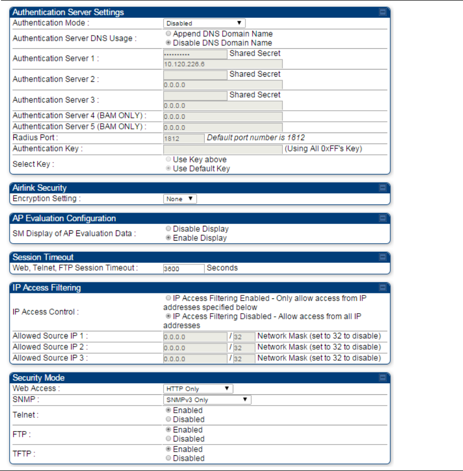
Chapter 7: Configuration Configuring a RADIUS server
Page 7-229
Table 182 Security tab attributes

Chapter 7: Configuration Configuring a RADIUS server
Page 7-230
Attribute Meaning
Authentication Mode Operators may use this field to select the following authentication modes:
Disabled—the AP requires no SMs to authenticate.
Authentication Server —the AP requires any SM that attempts registration
to be authenticated in Wireless Manager before registration.
AP PreShared Key - The AP acts as the authentication server to its SMs and
will make use of a user-configurable pre-shared authentication key. The
operator enters this key on both the AP and all SMs desired to register to that
AP. There is also an option of leaving the AP and SMs at their default setting
of using the “Default Key”. Due to the nature of the authentication operation, if
you want to set a specific authentication key, then you MUST configure the
key on all of the SMs and reboot them BEFORE enabling the key and option
on the AP. Otherwise, if you configure the AP first, none of the SMs is able to
register.
RADIUS AAA - When RADIUS AAA is selected, up to 3 Authentication
Server (RADIUS Server) IP addresses and Shared Secrets can be
configured. The IP address(s) configured here must match the IP address(s)
of the RADIUS server(s). The shared secret(s) configured here must match
the shared secret(s) configured in the RADIUS server(s). Servers 2 and 3 are
meant for backup and reliability, not for splitting the database. If Server 1
doesn’t respond, Server 2 is tried, and then server 3. If Server 1 rejects
authentication, the SM is denied entry to the network and does not progress
trying the other servers.
Authentication Server
DNS Usage
The management DNS domain name may be toggled such that the name of
the authentication server only needs to be specified and the DNS domain
name is automatically appended to that name.
Authentication Server
1
Enter the IP address or server name of the authentication server (RADIUS or
WM) and the Shared Secret configured in the authentication server. When
Authentication Mode RADIUS AAA is selected, the default value of Shared
Secret is “CanopySharedSecret”. The Shared Secret may consist of up to 32
ASCII characters.
Authentication Server
2
Authentication Server
3
Authentication Server
4 (BAM Only)
Authentication Server
5 (BAM Only)
Radius Port This field allows the operator to configure a custom port for RADIUS server
communication. The default value is 1812.
Authentication Key The authentication key is a 32-character hexadecimal string used when
Authentication Mode is set to AP Pre-Shared Key. By default, this key is
set to 0xFFFFFFFFFFFFFFFFFFFFFFFFFFFFFFFF.
Selection Key This option allows operators to choose which authentication key is used:

Chapter 7: Configuration Configuring a RADIUS server
Page 7-231
Use Key above means that the key specified in Authentication Key is used
for authentication
Use Default Key means that a default key (based off of the SM’s MAC
address) is used for authentication
Encryption Key Specify the type of airlink security to apply to this AP. The encryption setting
must match the encryption setting of the SMs.
None provides no encryption on the air link.
DES (Data Encryption Standard): An over-the-air link encryption option that
uses secret 56-bit keys and 8 parity bits. DES performs a series of bit
permutations, substitutions, and recombination operations on blocks of data.
DES encryption does not affect the performance or throughput of the system.
AES (Advanced Encryption Standard): An over-the-air link encryption option
that uses the Rijndael algorithm and 128-bit keys to establish a higher level of
security than DES. AES products are certified as compliant with the Federal
Information Processing Standards (FIPS 197) in the U.S.A.
SM Display of AP
Evaluation Data
You can use this field to suppress the display of data about this AP on the AP
Evaluation tab of the Tools page in all SMs that register.
Web, Telnet, FTP
Session Timeout
Enter the expiry in seconds for remote management sessions via HTTP,
telnet, or ftp access to the AP.
IP Access Control You can permit access to the AP from any IP address (IP Access Filtering
Disabled) or limit it to access from only one, two, or three IP addresses that
you specify (IP Access Filtering Enabled). If you select IP Access Filtering
Enabled, then you must populate at least one of the three Allowed Source
IP parameters or have no access permitted from any IP address
Allowed Source IP 1 If you selected IP Access Filtering Enabled for the IP Access Control
parameter, then you must populate at least one of the three Allowed Source
IP parameters or have no access permitted to the AP from any IP address.
You may populate as many as all three.
Allowed Source IP 2 If you selected IP Access Filtering Disabled for the IP Access Control
parameter, then no entries in this parameter are read, and access from all IP
addresses is permitted.
Allowed Source IP 3
Web Access The Radio supports secured and non-secured web access protocols. Select
suitable web access from drop down list:
HTTP Only – provides non-secured web access. The radio to be
accessed via http://<IP of Radio>.
HTTPS Only – provides a secured web access. The radio to be accessed
via https1://<IP of Radio>.
HTTP and HTTPS – If enabled, the radio can be accessed via both http
and https.
SNMP This option allows to configure SNMP agent communication version. It can be
selected from drop down list :
SNMPv2c Only – Enables SNMP v2 community protocol.

Chapter 7: Configuration Configuring a RADIUS server
Page 7-232
SNMPv3 Only – Enables SNMP v3 protocol. It is secured communication
protocol.
SNMPv2c and SNMPv3 – It enables both the protocols.
Telnet This option allows to Enable and Disable Telnet access to the Radio.
FTP This option allows to Enable and Disable FTP access to the Radio.
TFTP This option allows to Enable and Disable TFTP access to the Radio.
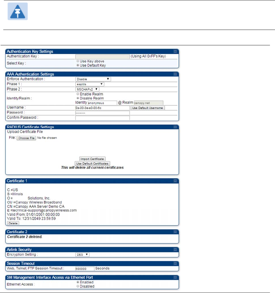
Chapter 7: Configuration Configuring a RADIUS server
Page 7-233
SM Authentication Mode – Require RADIUS or
Follow
AP
If it is desired that a SM will only authenticate to an AP that is using RADIUS, on the
SM’s
Configuration Security tab set
Enforce Authentication
to
AAA
. With this
enabled, SM
does
not
register to an AP that has any
Authentication Mode
other than
RADIUS AAA
selected
.
If it is desired that a SM use the authentication method configured on the AP it is
registering
to, set
Enforce Authentication
to
Disabled.
With
Enforce Authentication
disabled, a SM will attempt to
register
using
whichever
Authentication Mode
is configured on the AP it is attempting to register
to.
Note
Having SMs to use RADIUS by enabling
Enforce Authentication
avoids the security issue
of
SMs possibly registering to “rogue” APs, which have authentication
disabled.
Table 183
SM Security tab attributes
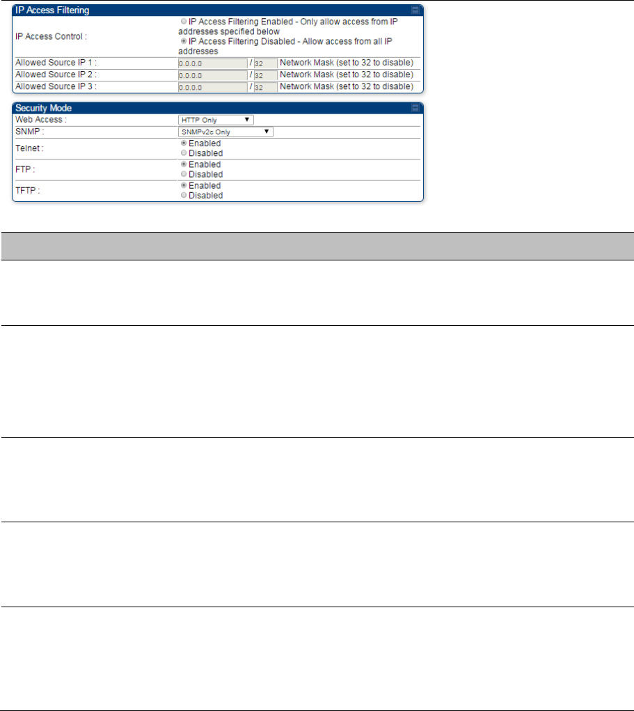
Chapter 7: Configuration Configuring a RADIUS server
Page 7-234
Attribute Meaning
Authentication Key
The authentication key is a 32-character hexadecimal string used when
Authentication Mode is set to AP PreShared Key. By default, this key is set
to 0xFFFFFFFFFFFFFFFFFFFFFFFFFFFFFFFF.
Select Key
This option allows operators to choose which authentication key is used:
Use Key above means that the key specified in Authentication Key is used
for authentication
Use Default Key means that a default key (based off of the SM’s MAC
address) is used for authentication
Enforce Authentication
The SM may enforce authentication types of AAA and AP Pre-sharedKey.
The SM will not finish the registration process if the AP is not using the
configured authentication method (and the SM locks out the AP for 15
minutes). Enforce Authentication default setting is Disable.
Phase 1
The protocols supported for the Phase 1 (Outside Identity) phase of
authentication are
EAPTTLS (Extensible Authentication Protocol Tunneled
Transport Layer
Security) or MSCHAPv2 (Microsoft Challenge-Handshake
Authentication Protocol version 2).
Phase 2
Select the desired Phase 2 (Inside Identity) authentication protocol from the
Phase 2 options
of
PAP (Password Authentication Protocol), CHAP
(Challenge Handshake
Authentication
Protocol), and MSCHAP (Microsoft’s
version of CHAP, version 2 is used). The protocol
must
be
consistent with
the authentication protocol configured on the RADIUS
server.

Chapter 7: Configuration Configuring a RADIUS server
Page 7-235
Identity/Realm
If Realms are being used, select Enable Realm and configure an outer
identity in the
Identity
field and a Realm in the Realm field. These must
match the Phase 1/Outer Identity and
Realm
configured in the RADIUS
server. The default Identity is “anonymous”. The Identity can be
up
to
128
non-special (no diacritical markings) alphanumeric characters. The default
Realm
is
“canopy.net”. The Realm can also be up to 128 non-special
alphanumeric
characters.
Configure an outer Identity in the Username field. This must match the
Phase
1/Outer
Identity username configured in the RADIUS server. The
default Phase 1/Outer
Identity
Username is “anonymous”. The Username
can be up to 128 non-special (no
diacritical
markings) alphanumeric
characters.
Username
Enter a Username for the SM. This must match the username configured
for the SM on
the
RADIUS server. The default Username is the SM’s MAC
address. The Username can be up
to
128 non-special (no diacritical
markings) alphanumeric
characters.
Password Enter the desired password for the SM in the Password and Confirm
Password fields.
The
Password must match the password configured for
the SM on the RADIUS server.
The
default Password is “password”. The
Password can be up to 128 non-special (no
diacritical
markings)
alphanumeric
characters.
Confirm Password
Upload Certificate File
To upload a certificate manually to a SM, first load it in a known place on
your PC
or
network
drive, then click on a Delete button on one of the
Certificate description blocks
to
delete a certificate to provide space for your
certificate. Click on Choose File, browse to
the
location of the certificate,
and click the Import Certificate button, and then reboot the radio
to
use the
new certificate.
When a certificate is in use, after the SM successfully registers to an AP, an
indication of In
Use
will appear in the description block of the certificate
being
used.
The public certificates installed on the SMs are used with the private
certificate on the
RADIUS
server to provide a public/private key encryption
system.
Up to 2 certificates can be resident on a SM. An installed certificate can be
deleted
by
clicking the Delete button in the certificate’s description block on
the Configuration >
Security
tab. To restore the 2 default certificates, click
the Use Default Certificates button in
the
RADIUS Certificate Settings
parameter block and reboot the
radio.

Chapter 7: Configuration Configuring a RADIUS server
Page 7-236
Encryption Setting
Specify the type of airlink security to apply to this AP. The encryption setting
must match the encryption setting of the SMs.
None provides no encryption on the air link.
DES (Data Encryption Standard): An over-the-air link encryption option that
uses secret 56-bit keys and 8 parity bits. DES performs a series of bit
permutations, substitutions, and recombination operations on blocks of data.
DES encryption does not affect the performance or throughput of the system.
AES (Advanced Encryption Standard): An over-the-air link encryption option
that uses the Rijndael algorithm and 128-bit keys to establish a higher level of
security than DES. AES products are certified as compliant with the Federal
Information Processing Standards (FIPS 197) in the U.S.A.
Web, Telnet, FTP
Session Timeout
Enter the expiry in seconds for remote management sessions via HTTP,
telnet or ftp access to the AP.
Ethernet Access
If you want to prevent any device that is connected to the Ethernet port of the
SM from accessing the management interface of the SM, select Ethernet
Access Disabled. This selection disables access through this port to via
HTTP (the GUI), SNMP, telnet, FTP, and TFTP. With this selection,
management access is available through only the RF interface via either an
IP address (if Network Accessibility is set to Public on the SM) or the
Session Status or Remote Subscribers tab of the AP. See IP Access Control
below.
If you want to allow management access through the Ethernet port, select
Ethernet Access Enabled. This is the factory default setting for this
parameter.
IP Access Control
You can permit access to the AP from any IP address (IP Access Filtering
Disabled) or limit it to access from only one, two, or three IP addresses that
you specify (IP Access Filtering Enabled). If you select IP Access Filtering
Enabled, then you must populate at least one of the three Allowed Source
IP parameters or have no access permitted from any IP address
Allowed Source IP 1 If you selected IP Access Filtering Enabled for the IP Access Control
parameter, then you must populate at least one of the three Allowed Source
IP parameters or have no access permitted to the AP from any IP address.
You may populate as many as all three.
If you selected IP Access Filtering Disabled for the IP Access Control
parameter, then no entries in this parameter are read, and access from all IP
addresses is permitted.
Allowed Source IP 2
Allowed Source IP 3
Web Access The Radio supports secured and non-secured web access protocols. Select
suitable web access from drop down list:
HTTP Only – provides non-secured web access. The radio to be
accessed via http://<IP of Radio>.
HTTPS Only – provides a secured web access. The radio to be accessed
via https://<IP of Radio>.

Chapter 7: Configuration Configuring a RADIUS server
Page 7-237
HTTP and HTTPS – If enabled, the radio can be accessed via both http
and https.
SNMP This option allows to configure SNMP agent communication version. It can be
selected from drop down list :
SNMPv2c Only – Enables SNMP v2 community protocol.
SNMPv3 Only – Enables SNMP v3 protocol. It is secured communication
protocol.
SNMPv2c and SNMPv3 – It enables both the protocols.
Telnet This option allows to Enable and Disable Telnet access to the Radio.
FTP This option allows to Enable and Disable FTP access to the Radio.
TFTP This option allows to Enable and Disable TFTP access to the Radio.
SM - Phase 1 (Outside Identity) parameters and
s
ettin
gs
The protocols supported for the Phase 1 (Outside Identity) phase of authentication
are
eapttls (Extensible Authentication Protocol Tunneled Transport Layer
Security) and
eapMSChapV2
(Extensible Authentication Protocol – Microsoft Challenge-Handshake Authentication Protocol).
Configure an outer Identity in the Username field. This must match the Phase
1/Outer
Identity
username configured in the RADIUS server. The default Phase 1/Outer
Identity
Username is
“anonymous”. The Username can be up to 128 non-special (no
diacritical
markings) alphanumeric
characters.
If Realms are being used in the RADIUS system (eapttls only), select Enable Realm and
configure an outer identity in the
Identity
field and a Realm in the Realm field. These must match the Phase
1/Outer Identity and
Realm
configured in the RADIUS server. The default Identity is “anonymous”. The
Identity can be
up
to
128 non-special (no diacritical markings) alphanumeric characters. The default Realm
is
“canopy.net”. The Realm can also be up to 128 non-special alphanumeric
characters.
SM - Phase 2 (Inside Identity) parameters and
s
ettin
gs
If using eapttls for Phase 1 authentication, select the desired Phase 2 (Inside Identity) authentication
protocol from the Phase 2 options
of
PAP (Password Authentication Protocol), CHAP (Challenge
Handshake
Authentication
Protocol), and MSCHAPv2 (Microsoft’s version of CHAP). The protocol
must
be
consistent with the authentication protocol configured on the RADIUS
server.
Enter a
Username for the SM. This must match the username configured for the SM on
the
RADIUS server.
The default Username is the SM’s MAC address. The Username can be up
to
128 non-special (no
diacritical markings) alphanumeric
characters.
Enter the desired password for the SM in the Password and Confirm Password fields.
The
Password
must match the password configured for the SM on the RADIUS server.
The
default Password is
“password”. The Password can be up to 128 non-special (no
diacritical
markings) alphanumeric
characters.

Chapter 7: Configuration Configuring a RADIUS server
Page 7-238
Handling Certificates
Managing SM Certificates via the SM GUI
The default public Canopy certificates are loaded into SMs upon factory software installation. The
default certificates are not secure and are intended for
use
during lab and field trials as part of gaining
experience with the RADIUS functionalities or as
an
option during debug. For secure operation, an
operator will want to create or procure their
own
certificates. Resetting a SM to its factory defaults will
remove the current certificates and restore the default certificates.
Up to two certificates can be resident on a SM. An installed certificate can be deleted
by
clicking the
Delete button in the certificate’s description block on the Configuration >
Security
tab. To restore the 2
default certificates, click the Use Default Certificates button in
the
RADIUS Certificate Settings
parameter block and reboot the
radio.
To upload a certificate manually to a SM, first load it in a known place on your PC
or
network
drive,
then click on a Delete button on one of the Certificate description blocks
to
delete a certificate to
provide space for your certificate. Click on Choose File, browse to
the
location of the certificate, and
click the Import Certificate button, and then reboot the radio
to
use the new certificate.
When a certificate is in use, after the SM successfully registers to an AP, an indication of In
Use
will
appear in the description block of the certificate being
used.
The public certificates installed on the SMs are used with the private certificate on the
RADIUS
server
to provide a public/private key encryption
system.
Note
Root certificates of more than one level (Example - a certificate from someone who received
their CA from Verisign) fails. Certificates must be either root or self-signed.
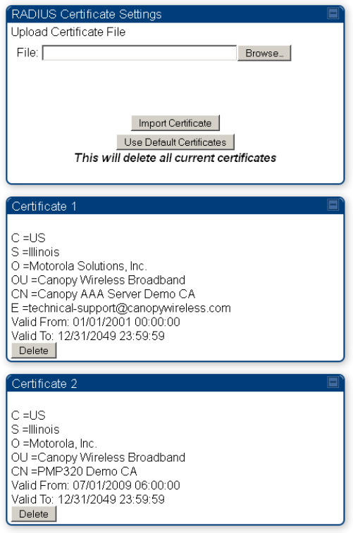
Chapter 7: Configuration Configuring a RADIUS server
Page 7-239
Figure 159 SM Certificate Management
Configuring RADIUS servers for SM authentication
Your RADIUS server must be configured to use the
following:
EAPTTLS or MSCHAPv2 as the Phase 1/Outer Identity
protocol.
If Enable Realm is selected on the SM’s Configuration > Security tab, then the
same
Realm
appears there (or access to it).
The same Phase 2 (Inner Identity) protocol as configured on the SM’s
Configuration
> Security
tab under Phase 2 options.
The username and password for each SM configured on each SM’s
Configuration
> Security
tab.
An IP address and NAS shared secret that is the same as the IP address
and
Shared Secret
configured on the AP’s Configuration > Security tab for
that
RADIUS server.

Chapter 7: Configuration Configuring a RADIUS server
Page 7-240
A server private certificate, server key, and CA certificate that complement
the
public certificates
distributed to the SMs, as well as the Canopy dictionary file
that
defines Vendor Specific Attributes
(VSAa). Default certificate files and
the
dictionary
file are available from the software
site:
https://support.cambiumnetworks.com/files/pmp450 after entering your
name,
email address, and
either Customer Contract Number or the MAC address of
a
module covered under the 12 month
warranty.
Optionally, operators may configure the RADIUS server response messages (Accept or Reject) so that
the user has information as to why they have been rejected. The AP displays the RADIUS Authentication
Reply message strings in the Session Status list as part of each SM’s information. The SM will show this
string (listed as Authentication Response on the SM GUI) on the main Status page in the Subscriber
Module Stats section.
Note
Aradial AAA servers only support operator-configurable Authentication Accept responses,
not Authentication Reject responses.

Chapter 7: Configuration Configuring a RADIUS server
Page 7-241
Assigning SM management IP addressing via RADIUS
Operators may use a RADIUS AAA server to assign management IP addressing to SM modules (framed
IP address). SMs now interpret attributes Framed-IP-Address, Framed-IP-Netmask, and Cambium-
Canopy-Gateway from RADIUS. The RADIUS dictionary file has been updated to include the Cambium-
Canopy-Gateway attribute and is available on the Cambium Software Support website.
In order for these attributes to be assigned and used by the SM, the following must be true:
The system is configured for AAA authentication
The SM is not configured for DHCP on its management interface. If DHCP is enabled and these
attributes are configured in the RADIUS server, the attributes is ignored by the SM.
The SM management interface must be configured to be publically accessible. If the SM is configured
to have local accessibility, the management interface will still be assigned the framed addressing, and
the SM iscome publicly accessible via the assigned framed IP addressing.
When using these attributes, for the addressing to be implemented by the SM operators must
configure Framed-IP-Address in RADIUS. If Framed-IP-Address is not configured but Framed-IP-
Netmask and/or Cambium-Canopy-Gateway is configured, the attributes is ignored. In the case
where only the Framed-IP-Address is configured, Framed-IP-Netmask defaults to 255.255.0.0 (NAT
disabled) / 255.255.255.0 (NAT enabled) and Cambium-Canopy-Gateway defaults to 0.0.0.0.
Configuring RADIUS server for SM configuration
Canopy Vendor Specific Attributes (VSAs) along with VSA numbers and
other
details are listed in Table
184. The associated SM GUI page, tab and parameter are listed to aid
cross-referencing
and
understanding of the
VSAs.
A RADIUS dictionary file is available from the software
site:
https://support.cambiumnetworks.com/files/pmp450
The RADIUS dictionary file
defines
the VSAs and their values and is usually imported into the RADIUS
server as part of
server
and database
setup.
Chapter 7: Configuration Configuring a RADIUS server
Page 7-242
Note
Beginning with System Release 12.0.2, two RADIUS dictionary files are available on the
Cambium website – “RADIUS Dictionary file – Cambium” and “RADIUS Dictionary file –
Motorola”.
In addition to a renaming of attributes, the Cambium-branded dictionary file contains two
new VSAs for controlling uplink and downlink Maximum Burst Data Rate (these VSAs are
listed below in Table 184).
If you are transitioning from the Motorola-branded dictionary file to the Cambium-branded
dictionary file, ensure that all RADIUS profiles containing Motorola-Canopy attribute
references are updated to include Cambium-Canopy attribute references (for all applicable
VSAs listed in Table 184). Also, ensure that all RADIUS configuration files reference the new
dictionary file (as an alternative, operators may rename the Cambium-branded dictionary file
to the filename currently in use by the RADIUS server). Once the profiles are updated and
the new Cambium-branded dictionary file is installed on the RADIUS server, restart the
RADIUS server to ensure that the new VSAs and attribute names are enabled.
Table 184 RADIUS Vendor Specific Attributes (VSAs)
Name Number Type Required Value
MS-MPPE-Send-Key
*
26.311.16
-
Y
-
-
- -
MS-MPPE-Recv-Key
*
26.311.17
-
Y
-
-
-
-
Cambium-Canopy-LPULCIR
26.161.1
integer N
0-65535
kbps
Configuration > Quality of Service > Low Priority Uplink
CIR
0
kbps
32 bits
Cambium-Canopy-LPDLCIR
26.161.2
integer N
0-65535
kbps
Configuration > Quality of Service > Low Priority Downlink
CIR
0
kbps
32 bits
Cambium-Canopy-HPULCIR
26.161.3
integer
N
0-65535
kbps
Configuration > Quality of Service > Hi Priority Uplink
CIR
0
kbps
32 bits
Cambium-Canopy-HPDLCIR
26.161.4
integer
N
0-65535
kbps
Configuration > Quality of Service > Hi Priority Uplink
CIR
0
kbps
32 bits
Cambium-Canopy-HPENABLE
26.161.5
integer
N
0-disable,
1-enable
Configuration > Quality of Service > Hi Priority
Channel
Enable/Disable
0
32 bits
26.161.6
integer
N
0-100000
kbps
Configuration > Quality of Service > Sustained Uplink
Data
Rate
dependent
on
radio
feature
set
32 bits

Chapter 7: Configuration Configuring a RADIUS server
Page 7-243
Cambium-Canopy-ULBL
26.161.7
integer
N
0-2500000
kbps
Configuration > Quality of Service > Uplink Burst
Allocation
dependent
on
radio
feature
set
32 bits
Cambium-Canopy-DLBR
26.161.8
integer N
0-100000
kbps
Configuration > Quality of Service > Sustained Downlink
Data
Rate
dependent
on
radio
feature
set
32 bits
Cambium-Canopy-DLBL
26.161.9
integer
N
0-2500000
kbps
Configuration > Quality of Service > Downlink Burst
Allocation
dependent
on
radio
feature
set
32 bits
Cambium-Canopy-
VLLEARNEN
26.161.14
integer
N
0-disable,
1-enable
Configuration > VLAN > Dynamic
Learning 1
32 bits
Cambium-Canopy-VLFRAMES
26.161.15 integer
N
0-all, 1-tagged,
2-
untagged
Configuration > VLAN > Allow Frame
Types 0
32 bits
Cambium-Canopy-VLIDSET
26.161.16 integer N
VLAN Membership
(1-
4094)
Configuration > VLAN
Membership 0
32 bits
Cambium-Canopy-VLAGETO
26.161.20 integer
N
5 - 1440
minutes
Configuration > VLAN > VLAN Aging
Timeout
25
mins
32 bits
Cambium-Canopy-VLIGVID
26.161.21
integer
N
1 –
4094
Configuration > VLAN > Default Port
VID 1
32 bits
Cambium-Canopy-VLMGVID
26.161.22 integer
N
1 –
4094
Configuration > VLAN > Management
VID 1
32 bits
Cambium-Canopy-
VLSMMGPASS
26.161.23 integer
N
0-disable,
1-enable
Configuration > VLAN > SM Management VID
Pass-through 1
32 bits
Cambium-Canopy-BCASTMIR
26.161.24 integer
N
0-100000 kbps,
0=disabled
Configuration > Quality of Service > Broadcast/Multicast
Uplink
Data
Rate
dependent
on
radio
feature
set
32 bits
Cambium-Canopy-Gateway
26.161.25 ipaddr N
-
Configuration > IP > Gateway IP Address
0.0.0.0 -
Cambium-Canopy-ULMB 26.161.26
integer
N
0-100000 kbps
Configuration > Quality of Service > Max Burst Uplink Data Rate
0 32 bits

Chapter 7: Configuration Configuring a RADIUS server
Page 7-244
Cambium-Canopy-DLMB 26.161.27
integer
N
0-100000 kbps
Configuration > Quality of Service > Max Burst Downlink Data
Rate
0 32 bits
Cambium-Canopy-UserLevel 26.161.50
integer
N
1-Technician,
2-
Installer, 3-
Administrator
Account > Add User >
Level 0
32 bits
Cambium-Canopy-DHCP-State 26.161.31 integer N 1-Enable
Configuration > IP > DHCP
state
1 32 bits
Cambium-Canopy-
BCASTMIRUNITS
26.161.28
integer
N
Configuration > QoS >
Broadcast Downlink CIR
0
32 bits
Cambium-Canopy-
ConfigFileImportUrl
26.161.29
string
N
Configuration > Unit Settings
0 32 bits
Cambium-Canopy-
ConfigFileExportUrl
26.161.30 string N
Configuration > Unit Settings 0 32 bits
Cambium-Canopy-UserMode 26.161.51 integer N 1=Read-Only 0=Read-
Write
Account > Add User > User
Mode
0 32 bits
(*) Contains key for encrypting packets sent by the NAS to the remote host (for Microsoft Point-to-Point
Encryption Protocol).
Note
VSA
numbering:
26 connotes Vendor Specific Attribute, per RFC
2865
26.311 is Microsoft Vendor Code, per
IANA

Chapter 7: Configuration Configuring a RADIUS server
Page 7-245
Configuring RADIUS server for SM configuration
using Zero Touch feature
The RADIUS VSA (Vendor Specific Attributes) is updated for Zero Touch feature. This feature enables
the ability for a SM to get its configuration via RADIUS VSA. The RADIUS VSA is updated for an URL
which points to the configuration file of SM (see Table 184 for list of VSA).
The RADIUS will push the vendor specific attribute to SM after successful authentication. The VSA
contains URL of config file which will redirect SM to download configuration. If there is any change in SM
confirmation, the SM will reboot automatically after applying the configuration.
The RADIUS VSA attributes concerning Zero Touch are as follows:
VSA Type String
Cambium-Canopy-ConfigFileImportUrl (29) string Maximum Length 127
characters.
Cambium-Canopy-ConfigFileExportUrl (30) string Maximum Length 127
characters.
The updated RADIUS dictionary can be downloaded from below link:
https://support.cambiumnetworks.com/files/pmp450/
Note
The feature is not applicable to the AP.

Chapter 7: Configuration Configuring a RADIUS server
Page 7-246
Using RADIUS for centralized AP and SM user name
and password management
AP – Technician/Installer/Administrator
Authenti
c
ation
To control technician, installer, and administrator access to the AP from a centralized
RADIUS server:
Procedure 28 Centralized user name and password management for AP
1 Set Authentication Mode on the AP’s Configuration > Security tab
to
RADIUS AAA
2 Set User Authentication Mode on the AP’s Account > User Authentication
tab
(the tab only
appears after the AP is set to RADIUS authentication) to
Remote
or Remote then
Local
.
Local: The local SM is checked for accounts. No centralized
RADIUS
accounting
(access control)
is
performed.
Remote: Authentication by the centralized RADIUS server
is
required to gain access to
the SM if the SM is registered to an
AP
that has RADIUS AAA Authentication Mode
selected. For up to
2
minutes a test pattern is displayed until the server responds
or
times
out.
Remote then Local: Authentication using the centralized
RADIUS
server is attempted. If
the server sends a reject message, then
the
setting of Allow Local Login after Reject
from AAA determines
if
the local user database is checked or not. If the configured
servers
do
not respond within 2 minutes, then the local user database
is
used. The
successful login method is displayed in the
navigation
column of the SM.
User administration and authentication separation
On the AP, it is possible to configure up to three User Authentication servers, along with their Shared
Secret. If none of the User Authentication servers are configured, the AP continues to use SM
Authorization servers for User Authentication.
If at least one of the IP addresses is configured, all Authentication, Authorization, and Accounting
requests now follow the newly configured User Authorization server.
To configure separate User Authentication and SM Authentication:
Chapter 7: Configuration Configuring a RADIUS server
Page 7-247
Procedure 29 User administration and authentication separation
1 Go to the AP’s Account > User Authentication And Access Tracking tab
2 Set User Authentication Mode to Remote or Remote then Local.
3 Set User Authentication Method to EAP-MD5 or EAP-PEAP-MSCHAPv2
4 Configure the Shared Secrets and IP Addresses of:
User Authentication Server 1
User Authentication Server 2
User Authentication Server 3
Note: If none of the above User Authentication servers are configured, only SM authentication
will be performed.
5 Under RADIUS Certificate Settings, click Browse to upload the RADIUS Certificate files.
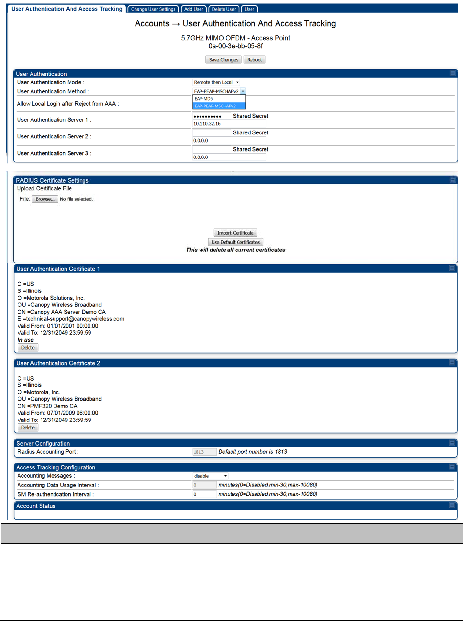
Chapter 7: Configuration Configuring a RADIUS server
Page 7-248
Table 185 AP User Authentication and Access Tracking attributes
Attribute Meaning
User Authentication
Mode
Local: The local SM is checked for accounts. No centralized
RADIUS
accounting (access control)
is
performed.
Remote: Authentication by the centralized RADIUS server
is
required to
gain access to the AP. For up to
2
minutes a test pattern is displayed
until the server responds
or
times
out.

Chapter 7: Configuration Configuring a RADIUS server
Page 7-249
Remote then Local: Authentication using the centralized
RADIUS
server is attempted. If the server sends a reject message, then
the
setting of Allow Local Login after Reject from AAA determines
if
the
local user database is checked or not. If the configured
servers
do
not
respond within 2 minutes, then the local user database
is
used. The
successful login method is displayed in the
navigation
column of the
AP.
User Authentication
Method
The user authentication method employed by the radios:
EAP-MD5
EAP-PEAP-MSCHAPv2
Allow Local Login after
Reject from AAA
If a user authentication is rejected from the AAA server, the user is allowed to
login locally to the radio’s management interface.
User Authentication
Server 1
The IP address and the shared secret key of the User authentication RADIUS
server 1.
User Authentication
Server 2
The IP address and the shared secret key of the User Authentication Server
2 configured in RADIUS Server.
User Authentication
Server 3
The IP address and the shared secret key of the User Authentication Server
3 configured in RADIUS Server.
RADIUS Certificate
Settings
Import Cetificate – browse and select the file to be uploaded and click on
“Import Certificate” to import a new certificate.
Use Default Certificates – use the preloaded default certificates.
User Authentication
Certificate 1
Cerificate provided by default for User authentication.
User Authentication
Certificate 2
Cerificate provided by default for User authentication.
Radius Accounting Port The destination port on the AAA server used for Radius accounting
communication.
Accounting Messages
disable – no accounting messages are sent to the RADIUS server.
deviceAccess – accounting messages regarding device access are sent to
the RADIUS server (see Table 187).
dataUsage – accounting messages regarding data usage are sent to the
RADIUS server (see Table 187).
All – accounting messages regarding device access and data usage are sent
to the RADIUS server.
Accounting Data Usage
Interval
The interval for which accounting data messages are sent from the radio to
the RADIUS server. If 0 is configured for this parameter, no data usage
messages are sent.
SM Re-authentication
Interval
The interval for which the SM will re-authenticate to the RADIUS server.
Account Status Displays the account status.
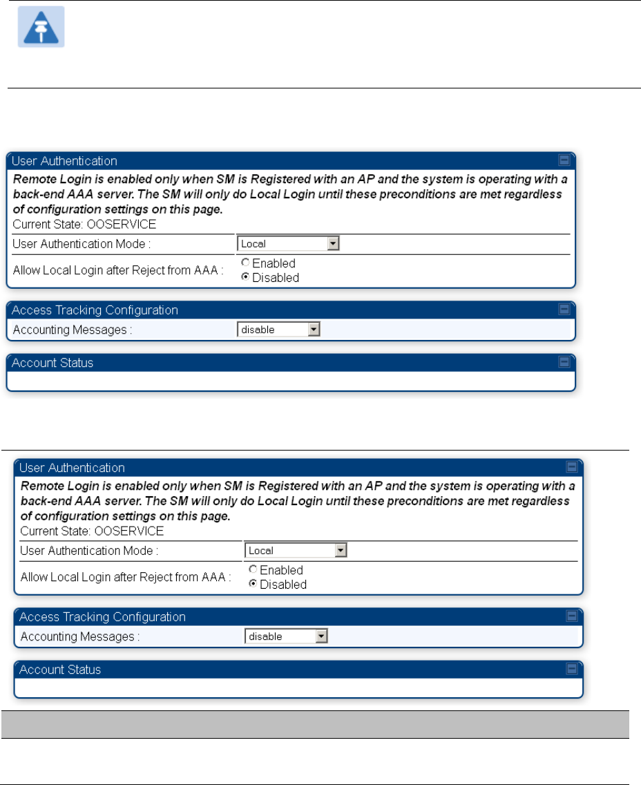
Chapter 7: Configuration Configuring a RADIUS server
Page 7-250
SM – Technician/Installer/Administrator
Authenti
c
ation
The centralized user name and password management for SM is same as AP. Follow AP –
Technician/Installer/Administrator Authentication on page 7-245 procedure.
Note
Remote access control is enabled only after the SM registers to an AP that has
Authentication Mode set to RADIUS AAA. Local access control will always be used before
registration and is used after registration if the AP is not configured for RADIUS.
Figure 160 User Authentication and Access Tracking tab of the SM
Table 186 SM User Authentication and Access Tracking attributes
Attribute Meaning
User Authentication
Mode
Local: The local SM is checked for accounts. No centralized RADIUS
accounting (access control) is performed.
Chapter 7: Configuration Configuring a RADIUS server
Page 7-251
Remote: Authentication by the centralized RADIUS server is required to
gain access to the SM if the SM is registered to an AP that has RADIUS
AAA Authentication Mode selected. For up to 2 minutes a test pattern is
displayed until the server responds or times out.
Remote then Local: Authentication using the centralized RADIUS server
is attempted. If the server sends a reject message, then the setting of
Allow Local Login after Reject from AAA determines if the local user
database is checked or not. If the configured servers do not respond
within 2 minutes, then the local user database is used. The successful
login method is displayed in the navigation column of the SM.
Allow Local Login after
Reject from AAA
If a user authentication is rejected from the AAA server, the user is allowed to
login locally to the radio’s management interface. It is applicable ONLY when
the User Authentication Mode is set to “Remote then Local”.
Note
When the radio User Authentication Mode is set to “Local” or
“Remote”, the Allow Local Login after Reject from AAA does
not any effect.
Accounting Messages
disable – no accounting messages are sent to the RADIUS server
deviceAccess – accounting messages are sent to the RADIUS server
regarding device access (see Table 187).
Access
T
ra
c
kin
g
To track logon and logoff times on individual radios by technicians, installers,
and
administrators, on the
AP or SM’s Account > User Authentication and Access Tracking tab
under
Accounting (Access
Tracking) set Accounting Messages to “deviceAccess”.
Device Access Tracking is enabled separately from User Authentication Mode. A given AP
or
SM
can be configured for both, either, or
neither.
RADIUS Device Data Accounting
PMP 450 Platform systems include support for RADIUS accounting messages for usage-based billing.
This accounting includes indications for subscriber session establishment, subscriber session
disconnection, and bandwidth usage per session for each SM that connects to the AP. The attributes
included in the RADIUS accounting messages are shown in the table below.
Table 187 Device data accounting RADIUS attributes
Sender Message Attribute Value Description
AP Acct-Status-Type 1 - Start

Chapter 7: Configuration Configuring a RADIUS server
Page 7-252
Sender Message Attribute Value Description
Accounting-
Request
Acct-Session-Id
Unique per AP session. Initial
value is SM MAC, and
increments after every start
message sent of an in
session SM.
This message is
sent every time a
SM registers with an
AP, and after the
SM stats are
cleared.
Event-Timestamp UTC time the event occurred
on the AP
AP Accounting-
Request
Acct-Status-Type 2 - Stop This message is
sent every time a
SM becomes
unregistered with an
AP, and when the
SM stats are
cleared.
Acct-Session-Id
Unique per AP session. Initial
value is SM MAC, and
increments after every start
message sent of an in
session SM.
Acct-Input-Octets
Sum of the input octets
received at the SM over
regular data VC and the high
priority data VC (if enabled).
Will not include broadcast.
Acct-Output-Octets
Sum of the output octets sent
from the SM over regular data
VC and the high priority data
VC (if enabled).
Acct-Input-
Gigawords
Number of times the Acct-
Input-Octets counter has
wrapped around 2^32 over
the course of the session
Acct-Output-
Gigawords
Number of times the Acct-
Output-Octets counter has
wrapped around 2^32 over
the course of the session
Acct-Input-Packets
Sum of unicast and multicast
packets that are sent to a
particular SM over the regular
data VC and the high priority
data VC (if enabled). It will not
include broadcast.
Acct-Output-Packets
Sum of unicast and multicast
packets that are sent from a
particular SM over the regular
data VC and the high priority
data VC (if enabled).

Chapter 7: Configuration Configuring a RADIUS server
Page 7-253
Sender Message Attribute Value Description
Acct-Session-Time Uptime of the SM session.
Acct-Terminate-
Cause
Reason code for session
termination
AP Accounting-
Request
Acct-Status-Type 3 - Interim-Update This message is
sent periodically per
the operator
configuration on the
AP in seconds.
Interim update
counts are
cumulative over the
course of the
session
Acct-Session-Id
Unique per AP session. Initial
value is SM MAC, and
increments after every start
message sent of an in
session SM.
Acct-Input-Octets
Sum of the input octets sent
to the SM over regular data
VC and the high priority data
VC (if enabled). Will not
include broadcast.
Acct-Output-Octets
Sum of the output octets set
from the SM over regular data
VC and the high priority data
VC (if enabled).
Acct-Input-
Gigawords
Number of times the Acct-
Input-Octets counter has
wrapped around 2^32 over
the course of the session
Acct-Output-
Gigawords
Number of times the Acct-
Output-Octets counter has
wrapped around 2^32 over
the course of the session
Acct-Session-Time Uptime of the SM session.
Acct-Input-Packets
Sum of unicast and multicast
packets that are sent to a
particular SM over the regular
data VC and the high priority
data VC (if enabled). It will not
include broadcast.
Acct-Output-Packets
Sum of unicast and multicast
packets that are sent from a
particular SM over the regular
data VC and the high priority
data VC (if enabled).
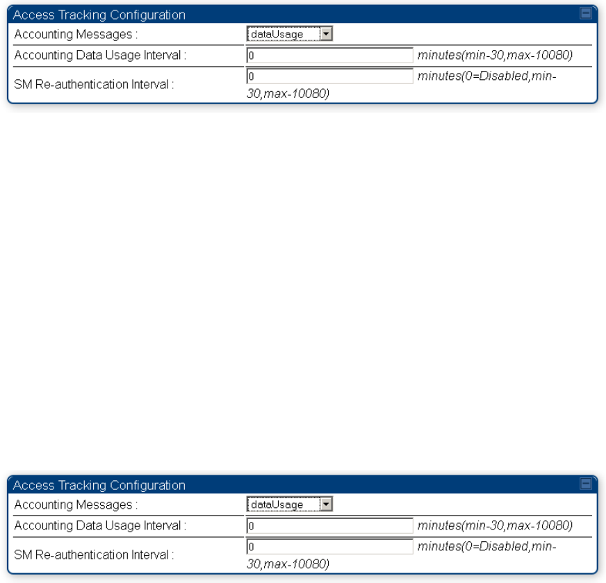
Chapter 7: Configuration Configuring a RADIUS server
Page 7-254
The data accounting configuration is located on the AP’s Accounts > User Authentication and Access
Tracking GUI menu, and the AP’s Authentication Mode must be set to Radius AAA for the menu to
appear. The accounting may be configured via the AP GUI as shown in the figures below. By default
accounting messages are not sent and the operator has the choice of configuring to send only Device
Access accounting messages (when a user logs in or out of the radio), only Data Usage messages, or
both. When Data Accounting is enabled, the operator must specify the interval of when the data
accounting messages are sent (0 – disabled, or in the range of 30-10080 minutes). The default interval is
30 minutes.
Figure 161 RADIUS accounting messages configuration
The data accounting message data is based on the SM statistics that the AP maintains, and these
statistics may be cleared on the AP by an operator. If an operator clears these messages and data
accounting is enabled, an accounting stop message is sent followed by an accounting start message to
notify the AAA of the change.
If an operator clears the VC statistics on the device through the management GUI, a RADIUS stop
message and data start message is issued for each device affected. The start and stop messages will
only be sent once every 5 minutes, so if an operator clears these statistics multiple times within 5
minutes, only one set of data stop/start messages is sent. This may result in inaccurate data
accumulation results.
RADIUS Device Re-authentication
PMP 450 Platform systems include support for periodic SM re-authentication in a network without
requiring the SM to re-register (and drop the session). The re-authentication may be configured to occur
in the range of every 30 minutes to weekly.
Figure 162 Device re-authentication configuration
The re-authentication interval is only configurable on the AP. When this feature is enabled, each SM that
enters the network will re-authenticate each the interval time has expired without dropping the session.
The response that the SM receives from the AAA server upon re-authentication is one of the following:
Success: The SM continues normal operation
Reject: The SM de-registers and will attempt network entry again after 1 minute and then if rejected
will attempt re-entry every 15 minutes
Chapter 7: Configuration Configuring a RADIUS server
Page 7-255
Timeout or other error: The SM remains in session and attempt 5 times to re-authenticate with the
RADIUS-REQUEST message. If these attempts fail, then the SM will go out of session and proceed
to re-authenticate after 5 minutes, then every 15 minutes.
Although re-authentication is an independent feature, it was designed to work alongside with the RADIUS
data usage accounting messages. If a user is over their data usage limit the network operator can reject
the user from staying in the network. Operators may configure the RADIUS ‘Reply-Message’ attribute with
an applicable message (i.e. “Data Usage Limit Reached”) that is sent to the subscriber module and
displayed on the general page.
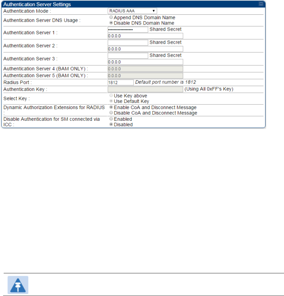
Chapter 7: Configuration Configuring a RADIUS server
Page 7-256
RADIUS Change of Authorization and Disconnect
Message
Prior to this feature, SM will get configuration parameters from a RADIUS server during authentication
process. This feature allows an administrator to control configuration parameters in the SM while SM is in
session. The configuration changes in SM are done using RADIUS Change of Authorization method
(RFC 3576) on the existing RADIUS authentication framework for AP and SM. A typical use case could
be changing the QOS parameters after a certain amount of bandwidth usage by a SM.
Figure 163 RADIUS CoA configuration for AP
The RADIUS CoA feature enables initiating a bi-directional communication from the RADIUS server(s) to
the AP and SM.
The AP listens on UDP port 3799 and accepts CoA requests from the configured RADIUS servers. This
CoA request should contain SM MAC address in ‘User-Name’ attribute as identifier and all other attributes
which control the SM config parameters. For security reasons, a timestamp also needs to be added as
‘Event-Timestamp’ attribute. Hence the time should also be synchronized between the RADIUS server(s)
and the AP to fit within a window of 300 seconds.
Once the configuration changes are applied on the SM, CoA-ACK message is sent back to RADIUS
server. If the validation fails, the AP sends a CoA-NACK response to the RADIUS server with proper error
code.
A Disconnect-Message is sent by the RADIUS server to NAS in order to terminate a user session on a
NAS and discard all associated session context. It is used when the authentication AAA server wants to
disconnect the user after the session has been accepted by the RADIUS.
In response of Disconnect-Request from RADIUS server, the NAS sends a Disconnect-ACK if all
associated session context is discarded, or a Disconnect-NACK, if the NAS is unable to disconnect the
session.
Note
The RADIUS CoA feature will only enabled if Authentication mode is set to RADIUS AAA.
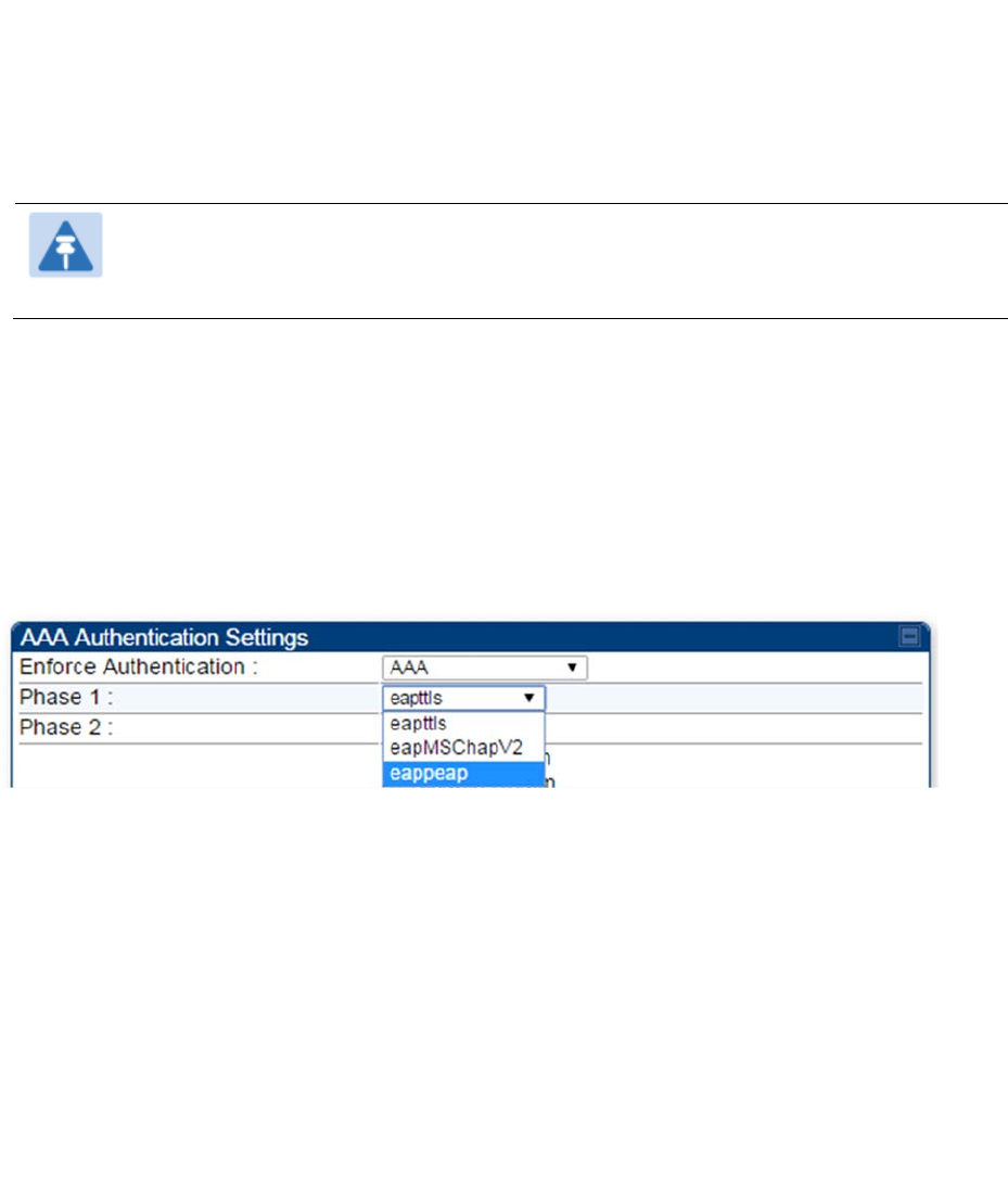
Chapter 7: Configuration Configuring a RADIUS server
Page 7-257
Microsoft RADIUS support
This feature allows to configure Microsoft RADIUS (Network Policy and Access Services a.k.a NPS)
as Authentication server for SM and User authentication.
For SM Authentication, SM will user PEAP-MSCHAPv2 since NPS doesn’t
support
TTLS protocol
.
For User Authentication, the Canopy software will use EAP-MD5 but the user has to do certain
configuration in order to enable EAP-MD5 on NPS.
Note
All this configuration has been tested on Windows Server 2012 R2 version.
This feature is not supported on hardware board type P9 or lower platforms.
SM Authentication Configuration
There are no new configuration on AP. However SM has to be configured for PEAP authentication
protocol.
1. Go to Configuration > Security page
2. Select “
eappeap
” for Phase 1 attribute under tab AAA Authentication Settings.
Figure 164
EAPPEAP settings
The Phase 2 will change automatically to MSCHAPv2 on select of Phase 1 attribute as EAP-PEAP. Other
parameters of Phase 2 protocols like PAP/CHAP will be disabled.
Windows Server Configuration
Import Certificate
The SM certificate has to be imported to Windows Server for certificate authentication.
1. Copy the certificate which is configured in SM under
Configuration > Security -> Certificate1
to
Windows Server machine.
2. Right click and select ‘Install Certificate’. This will install the certificate and it’s ready for use. This
certificate will be used while configuring PEAP-MSCHAPv2 in NPS.
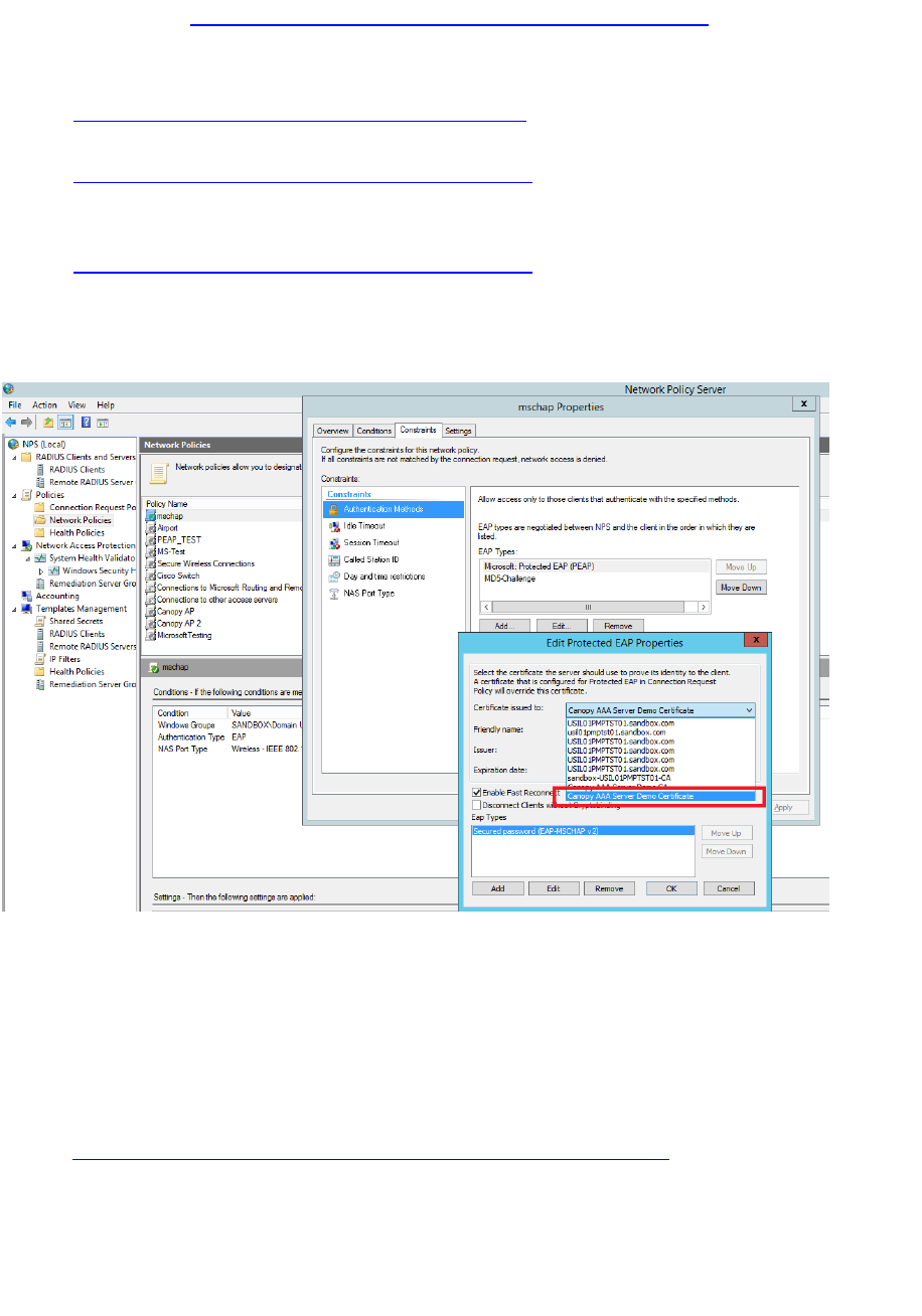
Chapter 7: Configuration Configuring a RADIUS server
Page 7-258
NPS Configuration (https://technet.microsoft.com/en-us/network/bb545879.aspx)
Following items should be configured in NPS Console:
RADIUS Client
o https://technet.microsoft.com/en-us/library/cc732929
Connection Request Policies
o https://technet.microsoft.com/en-us/library/cc730866
o Choose ‘Wireless-Other’ in NAS-Port-Type
Network Policy
o https://technet.microsoft.com/en-us/library/cc755309
o Choose ‘Wireless-Other’ in NAS-Port-Type.
o While configuring PEAP, select the above imported certificate.
Figure 165 Importing certificate in NPS
User Authentication Configuration
Enabling EAP-MD5
As mentioned earlier, Microsoft has deprecated the support for MD5 from versions of Windows. To enable
MD5, the following steps to be followed:
1. Follow the instructions:
https://support.microsoft.com/en-us/kb/922574/en-us?wa=wsignin1.0
Optionally, the registry file can be downloaded. It can be installed by double-click it in Windows
Registry.
2. From NPS Console Network Policy > <Policy Name> > Properties > Constrains >
Authentication Method and click Add. Select MD5 and click OK.
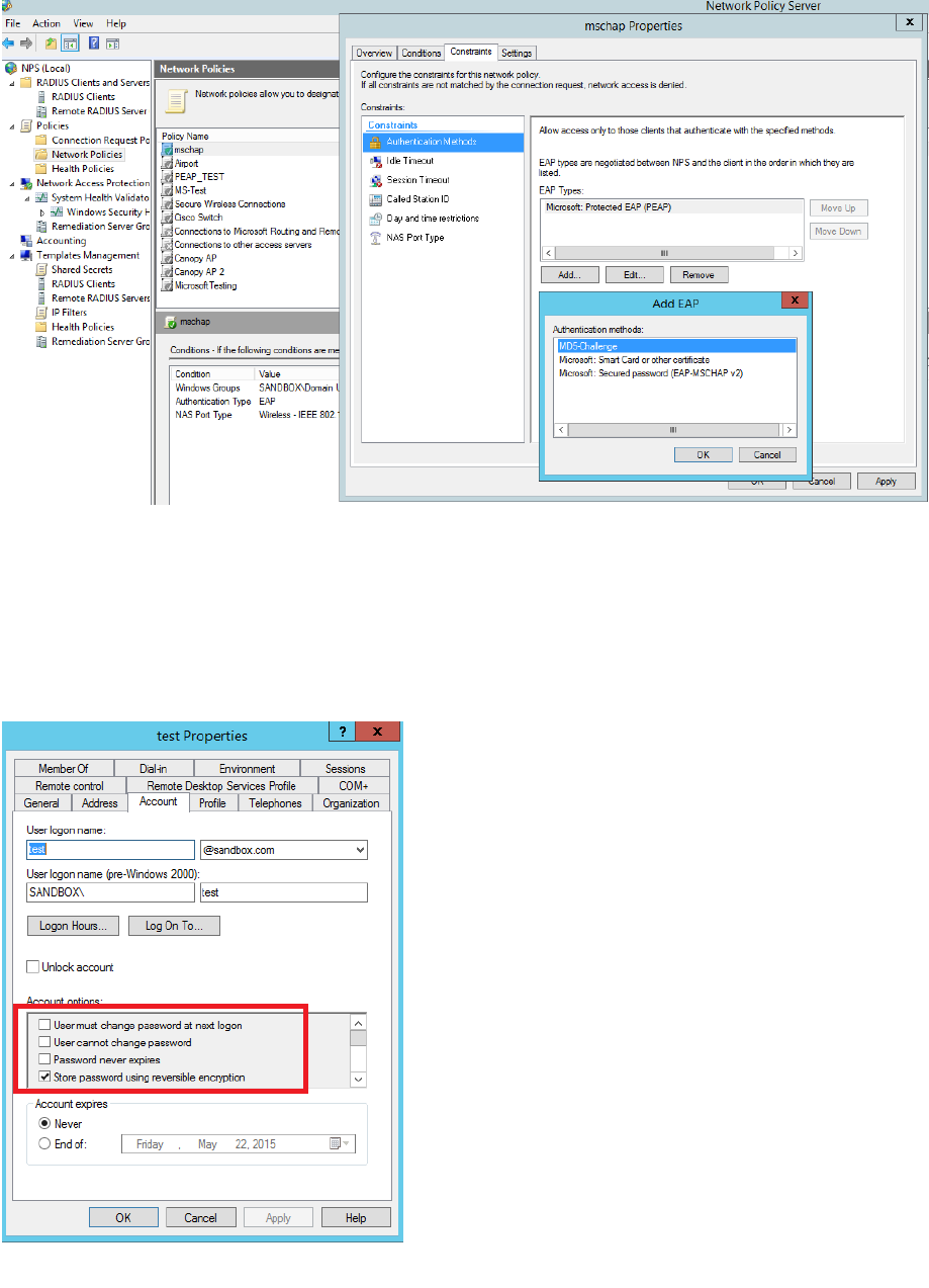
Chapter 7: Configuration Configuring a RADIUS server
Page 7-259
Figure 166 Selecting MD5 from NPS console
User Configuration in Active Directory
Next open ‘Active Directory Users and Computers’ and create user.
Make sure user property is configured as shown below.
Figure 167 User configuration
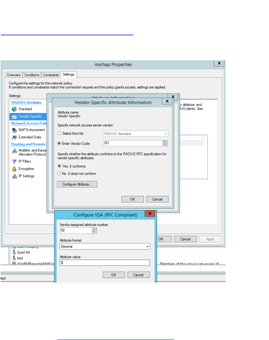
Chapter 7: Configuration Configuring a RADIUS server
Page 7-260
RADIUS VSA Configuration
Before using VSA, the Cambium-Canopy-UserLevel(50) VSA must be configured with some access
level say ADMIN(3).
Follow below link for configuring VSA:
https://technet.microsoft.com/en-us/library/cc731611
The Cambium’s vendor code is 161.
Figure 168 RADIUS VSA configuration
Accounting
User can enable accounting in NPS under NPS Console > Accounting >
Configure Accounting.
For more details refer https://technet.microsoft.com/library/dd197475
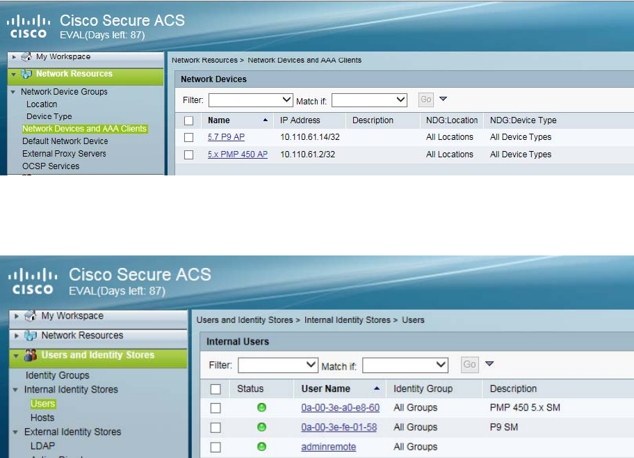
Chapter 7: Configuration Configuring a RADIUS server
Page 7-261
Cisco ACS RADIUS Server Support
This briefly explains how to configure Cisco ACS RADIUS server for PEAP-MSCHAPv2 authentication.
The configuration had been tested on CISCO ACS Version : 5.7.0.15
Adding RADIUS client
Figure 169 Adding RADIUS client
Creating Users
Figure 170 Creating users
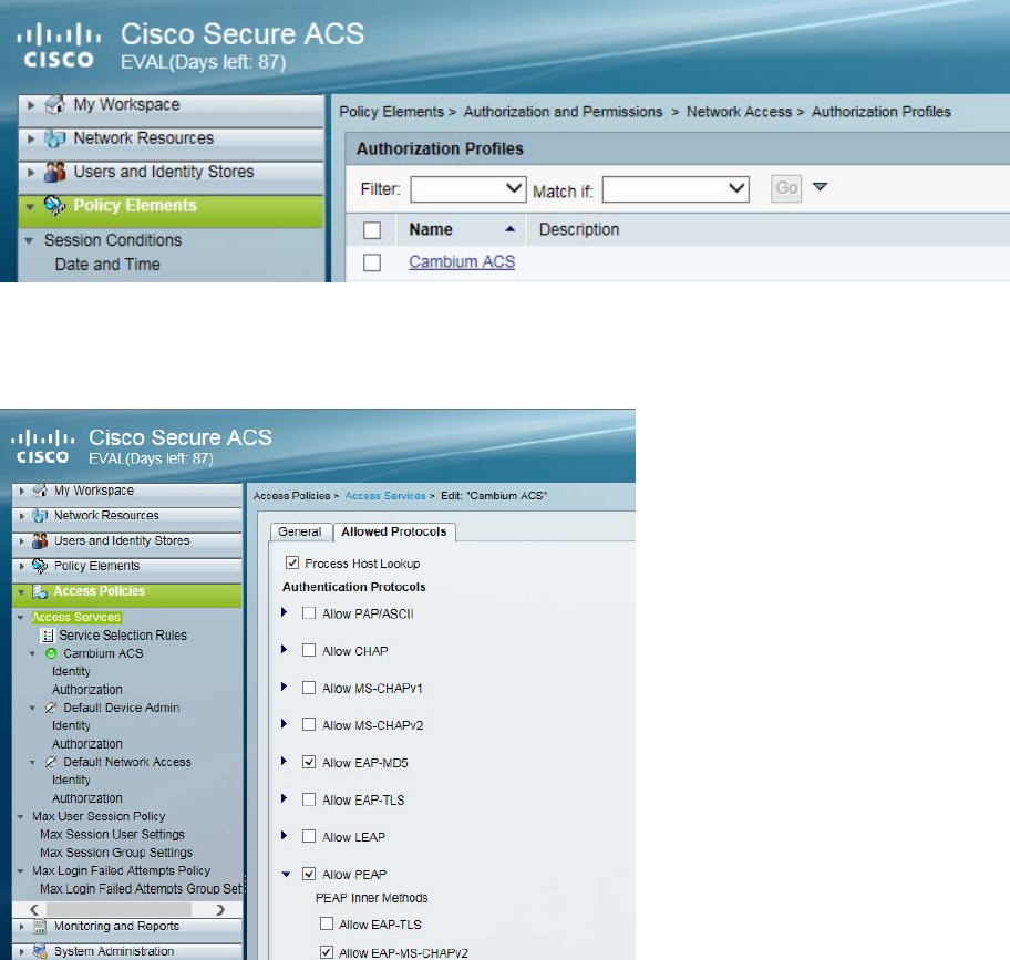
Chapter 7: Configuration Configuring a RADIUS server
Page 7-262
Creating RADIUS instance
Figure 171 Creating RADIUS instance
RADIUS protocols
Figure 172 RADIUS protocols
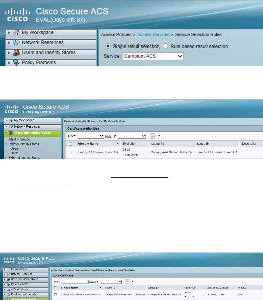
Chapter 7: Configuration Configuring a RADIUS server
Page 7-263
Service selection
Figure 173 Service selection
Adding Trusted CA
Figure 174 Adding Trusted CA
Note that certificate has to be in DER form, so if you have in PEM format convert using openssl.
Openssl.exe x509 -in <path-to->/cacert_aaasvr.pem -outform DER -out <path-
to>/cacert_aaasvr.der
Installing Server Certificate
After installing trusted CA, you need to add a server certificate which will be used for TLS tunnel.
Generally you have to install same certificate which is installed in your AP, so that AP can trust the radius
server.
Figure 175 Installing Server Certificate
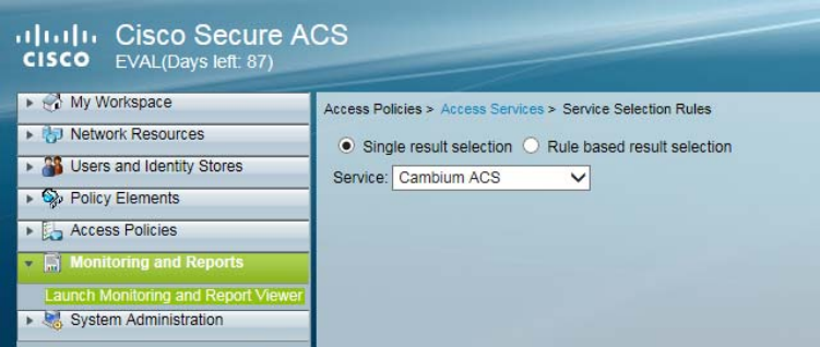
Chapter 7: Configuration Configuring a RADIUS server
Page 7-264
Monitoring Logs
Figure 176 Monitoring logs
Configuring VSA
Before using VSA , user has to add Cambium Vendor Specific Attribute
Navigate to System Administration > Configuration > Dictionaries > Protocols > RADIUS > RADIUS
VSA > Motorola
If Motorola is not present you can create Vendor with ID 161 and add all the VSA one by one.
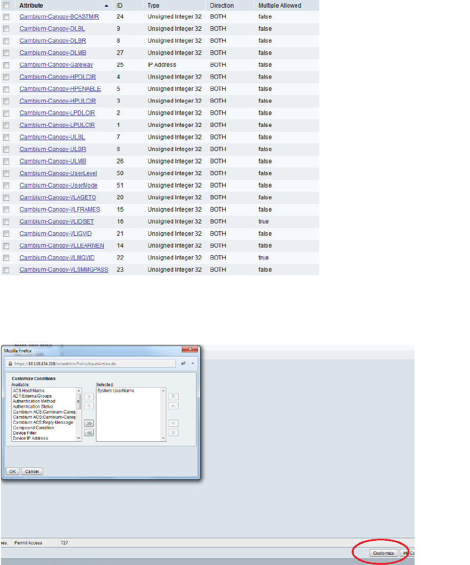
Chapter 7: Configuration Configuring a RADIUS server
Page 7-265
Figure 177 VSA list
Using VSA for users
Navigate to Access Policies > Access Services > Cambium ACS > Authorization
1. Change condition to User name
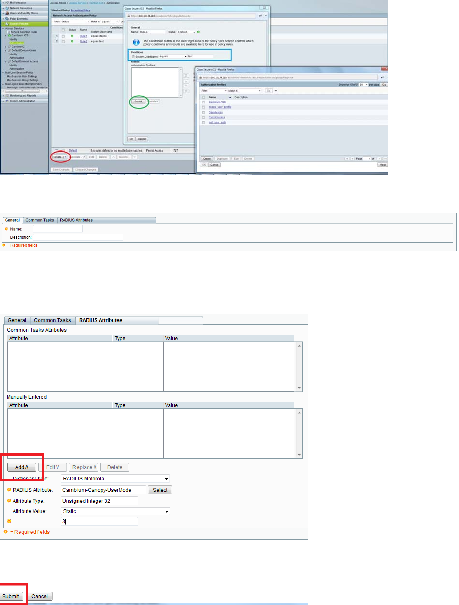
Chapter 7: Configuration Configuring a RADIUS server
Page 7-266
2. Next click Create and then click Select see diagram below
3. Click Create from the screen you get following screen
Chose some name and then move to RADIUS Attributes tab
4. Fill attribute which all you want for that particular user
Important: Click Add for each attribute and when done click Submit.
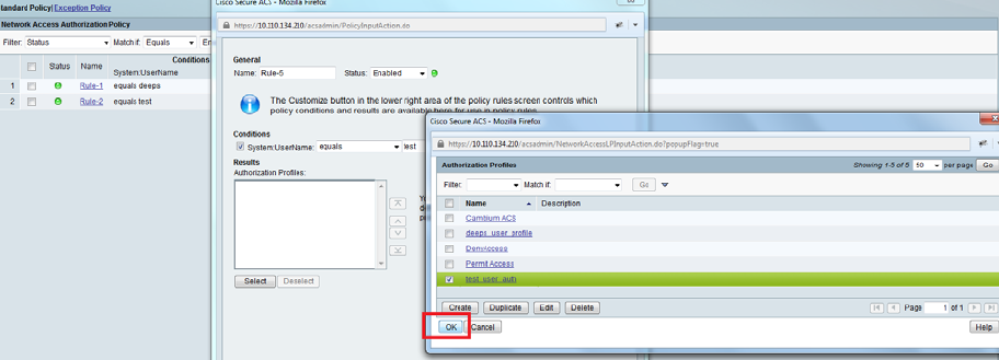
Chapter 7: Configuration Configuring a RADIUS server
Page 7-267
5. Now you are ready to use this Authorization profile for the use
Select and Press OK
6. Finally press Save Changes and you are ready to use it.
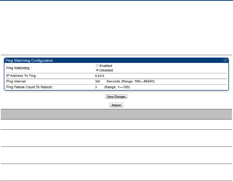
Chapter 7: Configuration Configuring Ping Watchdog
Page 7-268
Configuring Ping Watchdog
This feature allows administrator to automatically reboot an AP/SM when there is a network issue to avoid
power on reset of radios. This feature is disabled by default.
To enable Ping Watchdog feature, select the menu option Configuration > Ping Watchdog, and
configure the parameters listed in the following table.
Table 188 Ping Watchdog attributes
Attribute Meaning
Ping Watchdog This filed enables or disbales Ping Watchdog feature.
IP Address To Ping This field specifies the IPV4 address of the device which needs to be
pinged.
Ping Interval This field specifies the time interval at which ping needs to be initiated.
The time interval needs to be specified in seconds.
Ping Failure Count To
Reboot
This field specifies the count of ping failures at which reboot needs to be
initiated.

Page 8-1
Chapter 8: Tools
The AP and SM GUIs provide several tools to analyze the operating environment, system performance
and networking, including:
Using Spectrum Analyzer tool on page 8-2
Using the Alignment Tool on page 8-14
Using the Link Capacity Test tool on page 8-21
Using AP Evaluation tool on page 8-31
Using BHM Evaluation tool on page 8-35
Using the OFDM Frame Calculator tool on page 8-39
Using the Subscriber Configuration tool on page 8-43
Using the Link Status tool on page 8-44
Using BER Results tool on page 8-49
Using the Sessions tool on page 8-50
Using the Ping Test tool on page 8-51
Chapter 8: Tools Using Spectrum Analyzer tool
Page 8-2
Using Spectrum Analyzer tool
The integrated spectrum analyzer can be very useful as a tool for troubleshooting and RF planning, but is
not intended to replicate the accuracy and programmability of a high-end spectrum analyzer, which
sometime can be used for other purposes.
The AP/BHM and SM/BHS perform spectrum analysis together in the Sector Spectrum Analyzer tool.
Caution
On start of the Spectrum Analyzer on a module, it enters a scan mode and drops any RF
connection it may have had. When choosing Start Timed Spectrum Analysis, the scan is
run for the amount of time specified in the Duration configuration parameter. When
choosing Start Continuous Spectrum Analysis, the scan is run continuously for 24 hours,
or until stopped manually (using the Stop Spectrum Analysis button).
Any module can be used to see the frequency and power level of any detectable signal that is within, just
above, or just below the frequency band range of the module.
Note
Vary the days and times when you analyze the spectrum in an area. The RF environment
can change throughout the day or throughout the week.
Mapping RF Neighbor Frequencies
The neighbor frequencies can be analyzed using Spectrum Analyzer tool. Following modules allow user
to:
Use a BHS or BHM for PTP and SM or AP for PMP as a Spectrum Analyzer.
View a graphical display that shows power level in RSSI and dBm at 5 MHz increments throughout
the frequency band range, regardless of limited selections in the Custom Radio Frequency Scan
Selection List parameter of the SM/BHS.
Select an AP/BHM channel that minimizes interference from other RF equipment.
Caution
The following procedure causes the SM/BHS to drop any active RF link. If a link is dropped
when the spectrum analysis begins, the link can be re-established when either a 15 minute
interval has elapsed or the spectrum analyzer feature is disabled.
Temporarily deploy a SM/BHS for each frequency band range that need to monitor and access the
Spectrum Analyzer tab in the Tools web page of the module.
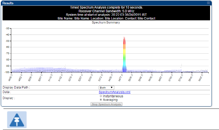
Chapter 8: Tools Using Spectrum Analyzer tool
Page 8-3
Using Spectrum Analyzer tool
Using the Remote Spectrum Analyzer tool
Spectrum Analyzer tool
Analyzing the spectrum
To use the built-in spectrum analyzer functionality of the AP/SM/BH, proceed as follows:
Procedure 30 Analyzing the spectrum
1 Predetermine a power source and interface that works for the AP/SM/BH in the area to
be analyzed.
2 Take the AP/SM/BH, power source and interface device to the area.
3 Access the Tools web page of the AP/SM/BH.
4 Enter Duration in Timed Spectrum Analyzer Tab. Default value is 10 Seconds
5 Click Start Timed Sector Spectrum Analysis
6 The results are displayed:
Figure 178 Spectrum analysis - Results
Note
AP/SM/BH scans for extra 40 seconds in addition to configured Duration
7 Travel to another location in the area to BHS.
8 Click Start Timed Spectrum Analysis
9 Repeat Steps 4 and 6 until the area has been adequately scanned and logged.
As with any other data that pertains to your business, a decision today to put the data into a retrievable
database may grow in value to you over time.
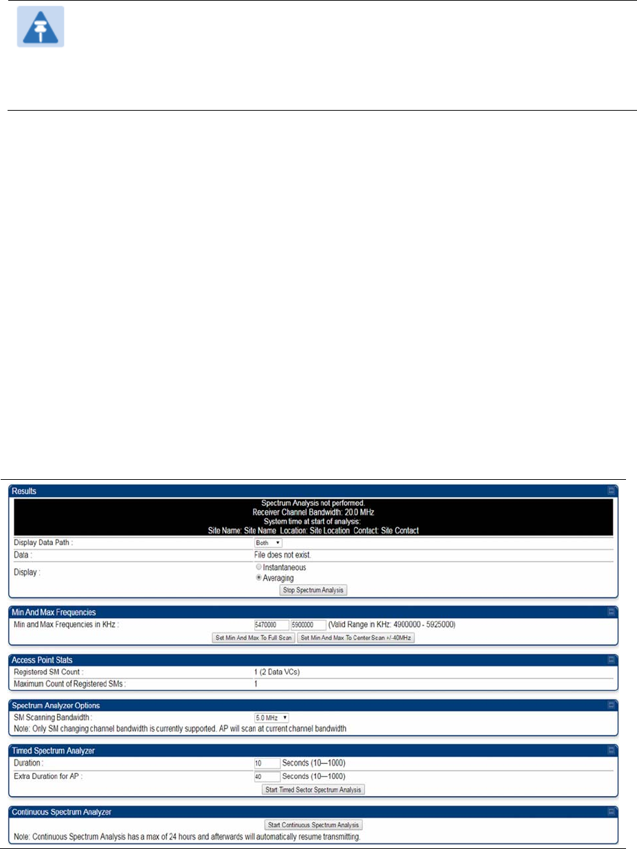
Chapter 8: Tools Using Spectrum Analyzer tool
Page 8-4
Note
Wherever the operator find the measured noise level is greater than the sensitivity of the
radio that is plan to deploy, use the noise level (rather than the link budget) for your link
feasibility calculations.
The AP/SM/BH perform spectrum analysis together in the Sector Spectrum Analyzer feature.
Graphical spectrum analyzer display
The AP/SM/BH display the graphical spectrum analyzer. An example of the
Spectrum Analyzer
page is
shown in Figure 178.
The navigation feature includes:
Results may be panned left and right through the scanned spectrum by clicking and dragging the
graph left and right
Results may be zoomed in and out using mouse
When the mouse is positioned over a bar, the receive power level, frequency, maximum and mean
receive power levels are displayed above the graph
To keep the displayed data current, either set “Auto Refresh” on the module’s
Configuration > General.
Spectrum Analyzer page of AP
The Spectrum Analyzer page of AP is explained in Table 189.
Table 189
Spectrum Analyzer page attributes - AP

Chapter 8: Tools Using Spectrum Analyzer tool
Page 8-5
Attribute Meaning
Display Data Path Both means that the vertical and horizontal paths are displayed or an
individual path may be selected to display only a single-path reading.
Data For ease of parsing data and to facilitate automation, the spectrum analyzer
results may be saved as an XML file. To save the results in an XML formatted
file, right-click the “SpectrumAnalysis.xml” link and save the file.
Display Instantaneous means that each reading (vertical bar) is displayed with two
horizontal lines above it representing the max power level received (top
horizontal line) and the average power level received (lower horizontal line) at
that frequency.
Averaging means that each reading (vertical bar) is displayed with an
associated horizontal line above it representing the max power level received
at that frequency.
Min and Max
Frequencies in KHz
Enter minimum and maximum frequencies to be scanned.
Set Min And Max to
Full Scan
On the button press, it sets mimimum and maximum allowed frequencies for
scanning.
Set Min And Max to
Center Scan +/-40
MHz
On the button press, it sets mimium and maximum frequencies to ± 40 MHz of
center frequency for scanning.
Registered SM Count This field displays the MAC address and Site Name of the registered SM.
Maximum Count of
Registered SMs
This field displays the maximum number of registered SMs.
SM Scanning
Bandwidth
This field allows to select SM’s scanning bandwidth.
Duration This field allows operators to configure a specified time for which the
spectrum is scanned. If the entire spectrum is scanned prior to the end of the
configured duration, the analyzer will restart at the beginning of the spectrum.
Continuous Spectrum
Analyzer
Start Continuous Spectrum Analysis button ensures that when the SM is
powered on, it automatically scans the spectrum for 10 seconds. These
results may then be accessed via the Tools > Spectrum Analyzer GUI page.
Spectrum Analyzer page of SM
The Spectrum Analyzer page of SM is explained in Table 190.
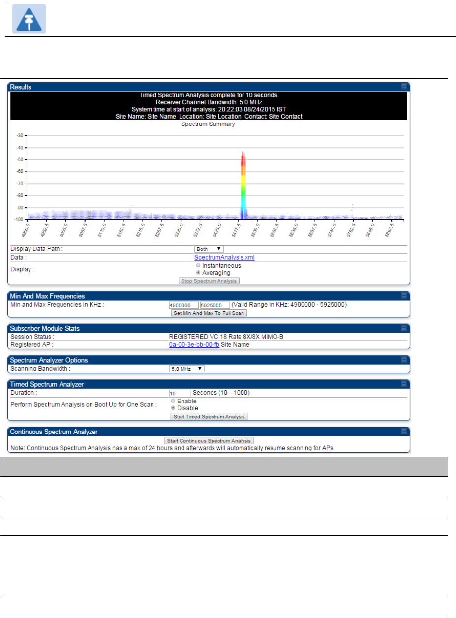
Chapter 8: Tools Using Spectrum Analyzer tool
Page 8-6
Note
Spectrum Analyzer is not currently supported by 450m.
Table 190 Spectrum Analyzer page attributes - SM
Attribute Meaning
Display Data Path Refer Table 189 on page 8-4
Data Refer Table 189 on page 8-4
Display Refer Table 189 on page 8-4
Min and Max
Frequencies in KHz
To scan min to max range of frequencies, enter min and max frequencies in
KHz and press Set Min and Max to Full Scan button.
To scan +/- 40 MHz from center frequency, enter center frequency in KHz and
press Set Min And Max To Center Scan +/- 40KHz button.
Registered SM Count Refer Table 189 on page 8-4
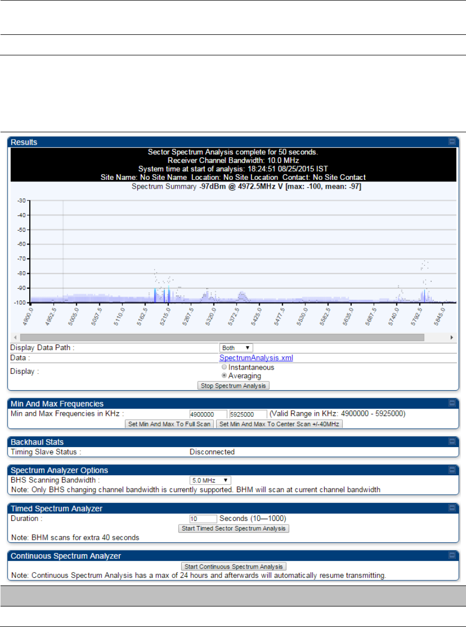
Chapter 8: Tools Using Spectrum Analyzer tool
Page 8-7
Maximum Count to
Registered SMs
Refer Table 189 on page 8-4
Duration Refer Table 189 on page 8-4
Spectrum Analyzer page of BHM
The Spectrum Analyzer page of BHM is explained in Table 191.
Table 191 Spectrum Analyzer page attributes - BHM
Attribute Meaning
Data Refer Table 189 on page 8-4
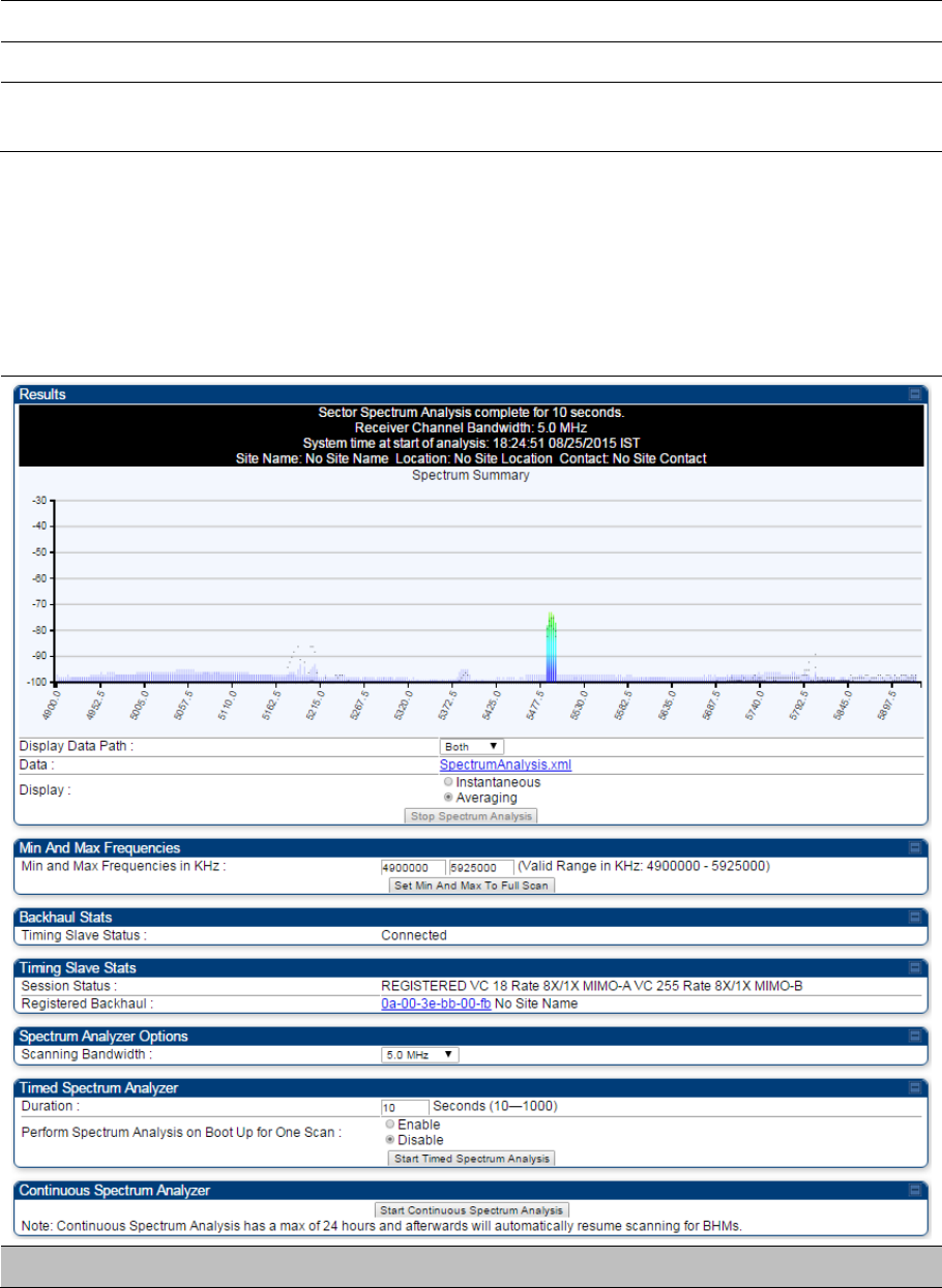
Chapter 8: Tools Using Spectrum Analyzer tool
Page 8-8
Display Refer Table 189 on page 8-4
Duration Refer Table 189 on page 8-4
Continuous Spectrum
Analyzer
Refer Table 189 on page 8-4
Spectrum Analyzer page of BHS
The Spectrum Analyzer page of BHS is explained in Table 192.
Table 192 Spectrum Analyzer page attributes - BHS
Attribute Meaning

Chapter 8: Tools Using Spectrum Analyzer tool
Page 8-9
Data Refer Table 189 on page 8-4
Display Refer Table 189 on page 8-4
Session Status This field displays current session status and rates. The session states can
be Scanning, Syncing, Registering or Registered.
Registered Backhaul This field displays MAC address of BHM and PTP model number
Duration Refer Table 189 on page 8-4
Perform Spectrum
Analysis on Boot Up
for one scan
This field allows to Enable or Disable to start Spectrum Analysis on boot up of
module for one scan.
Continuous Spectrum
Analyzer
Refer Table 189 on page 8-4
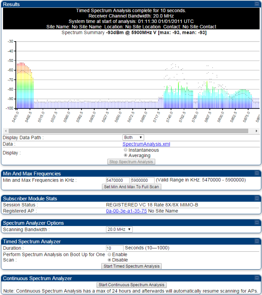
Chapter 8: Tools Using Spectrum Analyzer tool
Page 8-10
Spectrum Analyzer page result of PMP 450 SM
Figure 179 Spectrum Analyzer page result – PMP 450 SM
Chapter 8: Tools Using Spectrum Analyzer tool
Page 8-11
Remote Spectrum Analyzer tool
The Remote Spectrum Analyzer tool in the AP/BHM provides additional flexibility in the use of the
spectrum analyzer in the SM/BHS. Set the duration of 10 to 1000 seconds, then click the Start Remote
Spectrum Analysis button to launch the analysis from that SM/BHS.
In PMP configuration, a SM has to be selected from the drop-down list before launching Start Remote
Spectrum Analysis.
Analyzing the spectrum remotely
Procedure 31 Remote Spectrum Analyzer procedure
1 The AP/BHM de-registers the target SM/BHS.
2 The SM/BHS scans (for the duration set in the AP/BHM tool) to collect data for the
bar graph.
3 The SM/BHS re-registers to the AP/BHM.
4 The AP/BHM displays the bar graph.
The bar graph is an HTML file, but can be changed to an XML file, which is then easy to analyze through
the use of scripts that you may write for parsing the data. To transform the file to XML, click the
“SpectrumAnalysis.xml” link below the spectrum results. Although the resulting display appears mostly
unchanged, the bar graph is now coded in XML. You can now right-click on the bar graph for a Save
Target As option to save the Spectrum Analysis.xml file.
Remote Spectrum Analyzer page of AP
The Remote Spectrum Analyzer page of AP is explained in Table 193.
Chapter 8: Tools Using Spectrum Analyzer tool
Page 8-12
Table 193 Remote Spectrum Analyzer attributes - AP
Attribute Meaning
Registered SM Count This field displays the number of SMs that were registered to the AP before
the SA was started. This helps the user know all the SMs re-registered after
performing a SA.
Maximum Count of
Registered SMs
This field displays the largest number of SMs that have been simultaneously
registered in the AP since it was last rebooted. This count can provide some
insight into sector history and provide comparison between current and
maximum SM counts at a glance.
Current Subscriber
Module
The SM with which the Link Capacity Test is run.
Duration This field allows operators to configure a specified time for which the
spectrum is scanned. If the entire spectrum is scanned prior to the end of the
configured duration, the analyzer will restart at the beginning of the spectrum.
Scanning Bandwidth This parameter defines the size of the channel scanned when running the
analyzer.
Chapter 8: Tools Using Spectrum Analyzer tool
Page 8-13
Remote Spectrum Analyzer page of BHM
The Remote Spectrum Analyzer page of BHM is explained in Table 194.
Table 194 Remote Spectrum Analyzer attributes - BHM
Attribute Meaning
Duration Refer Table 189 on page 8-4
Chapter 8: Tools Using the Alignment Tool
Page 8-14
Using the Alignment Tool
The SM’s or BHS’s Alignment Tool may be used to maximize Receive Power Level, Signal Strength Ratio
and Signal to Noise Ratio to ensure a stable link. The Tool provides color coded readings to facilitate in
judging link quality.
Note
To get best performance of the link, the user has to ensure the maximum Receive Power
Level during alignment by pointing correctly. The proper alignment is important to prevent
interference in other cells. The achieving Receive Power Level green (>- 70 dBm) is not
sufficient for the link.
Figure 180 Alignment Tool tab of SM – Receive Power Level > -70 dBm
Figure 181 Alignment Tool tab of SM – Receive Power Level between -70 to -80 dBm
Figure 182 Alignment Tool tab of SM – Receive Power Level < -80 dBm

Chapter 8: Tools Using the Alignment Tool
Page 8-15
Aiming page and Diagnostic LED – SM/BHS
The SM’s/BHS’s Alignment Tool (located in GUI Tools -> Aiming) may be used to configure the
SM’s/BHS’s LED panel to indicate received signal strength and to display decoded beacon
information/power levels. The SM/BHS LEDs provide different status based on the mode of the SM/BHS.
A SM/BHS in “operating” mode will register and pass traffic normally. A SM/BHS in “aiming” mode will not
register or pass traffic, but will display (via LED panel) the strength of received radio signals (based on
radio channel selected via Tools ->Aiming). See SM/BHS LEDs on page 2-17.
Note
In order for accurate power level readings to be displayed, traffic must be present on the
radio link.
Refer Table 23 SM/BHS LED descriptions on page 2-18 for SM/BHS LED details.
Aiming page of SM
The Aiming page is similar to Spectrum Analyzer where it scans the spectrum but it does not establish
any session with any APs. It has two modes – Single Frequency Only and Normal Frequency Scan List.
The Aiming page of SM is explained in Table 195.
Chapter 8: Tools Using the Alignment Tool
Page 8-16
Table 195 Aiming page attributes – SM
Attribute Meaning
Aiming Mode Single Frequency Only: scans only selected single frequency.
Normal Frequency Scan List: scans: scans all frequency of scan list.
Single Frequency Select a particular frequency from drop down menu for scanning.
Scan Radio
Frequency Only Mode
Enabled: the radio is configured to “aiming” or “alignment” mode, wherein the
LED panel displays an indication of receive power level. See Table 23
SM/BHS LED descriptions on page 2-18.
Disabled: the radio is configured to “operating” mode, wherein the SM
registers and passes traffic normally.
Aiming Results The Aiming Results are displayed in two sections – Current entry and Other
entries.
Frequency: this field indicates the frequency of the AP which is transmitting
the beacon information.

Chapter 8: Tools Using the Alignment Tool
Page 8-17
Power: This field indicates the current receive power level (vertical channel)
for the frequency configured in parameter Radio Frequency.
Users: This field indicates the number of SMs currently registered to the AP
which is transmitting the beacon information.
ESN: This field indicates the MAC, or hardware address of the AP/BHM which
is transmitting the beacon information.
Color Code: This field displays a value from 0 to 254 indicating the AP’s
configured color code. For registration to occur, the color code of the SM and
the AP must match. Color code is not a security feature. Instead, color code is
a management feature, typically for assigning each sector a different color
code.
Color code allows you to force a SM to register to only a specific AP, even
where the SM can communicate with multiple APs. The default setting for the
color code value is 0. This value matches only the color code of 0 (not all 255
color codes).
Multipoint or Backhaul: this field indicates type of configuration - point-
Multipoint(PMP) or Backhaul (PTP).
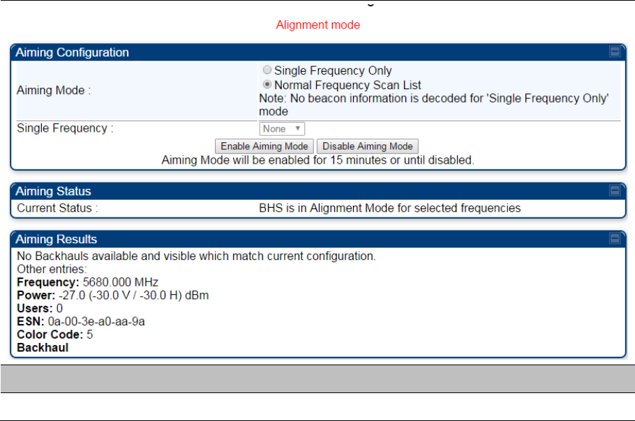
Chapter 8: Tools Using the Alignment Tool
Page 8-18
Aiming page of BHS
The Alignment page of BHS is explained in Table 196.
Table 196 Aiming page attributes - BHS
Attribute Meaning
Refer Table 161 for Atributes details.
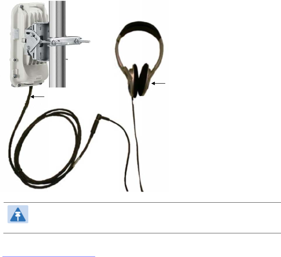
Chapter 8: Tools Using the Alignment Tool
Page 8-19
Alignment Tone
For coarse alignment of the SM/BHS, use the Alignment Tool located at
Tools ->
Alignment Tool
.
Optionally, connect a headset alignment tone kit to the AUX/SYNC port of the SM/BHS and listen to the
alignment tone, which indicates greater SM/BHS receive signal power by pitch. By adjusting the
SM’s/BHS’s position until the highest frequency pitch is obtained operators and installers can be confident
that the SM/BHS is properly positioned. For information on device GUI tools available for alignment, see
sections Aiming page and Diagnostic LED – SM/BHS on page 8-15, Using the Link Capacity Test tool on
page 8-21 and Using AP Evaluation tool on page 8-31.
Figure 183
PMP/PTP
450i Series link alignment tone
Note
The Alignment Tone cable for a 450i Series uses an RJ-45 to headset cable where as the
450 Series alignment tone cable uses an RJ-12 to headset cable.
Alignment Tool Headset and alignment tone adapters can be ordered from Cambium and Best-Tronics
(http://btpa.com/Cambium-Products/) respectively using the following part numbers:
Headphones
450i Alignment
tone adapter

Chapter 8: Tools Using the Alignment Tool
Page 8-20
Table 197 Alignment Tool Headsets and Alignment tone adapter third party product details
Reference Product description
ACATHS-01A Alignment tool headset for the PMP/PTP 450 and 450i Series products
BT-1277 Headset alignment cable (RJ-45) for the PMP/PTP 450i Series products
BT-0674 Headset alignment cable (RJ-12) for the PMP/PTP 450 Series products.

Chapter 8: Tools Using the Link Capacity Test tool
Page 8-21
Using the Link Capacity Test tool
The Link Capacity Test tab allows you to measure the throughput and efficiency of the RF link between
two modules. Many factors, including packet length, affect throughput.
The Link Capacity Test tool has following modes:
Link Test with Multiple VCs: Tests radio-to-radio communication across selected or all registered
VCs, but does not bridge traffic (PMP 450m Series AP only).
Link Test without Bridging: Tests radio-to-radio communication, but does not bridge traffic.
Link Test with Bridging: Bridges traffic to “simulated” Ethernet ports, providing a status of the
bridged link.
Link Test with Bridging and MIR: Bridges the traffic during test and also adheres to any MIR
(Maximum Information Rate) settings for the link.
Extrapolated Link Test: Estimates the link capacity by sending few packets and measuring link
quality.
The Link Capacity Test tab contains the settable parameter Packet Length with a range of 64 to 1714
bytes. This allows you to compare throughput levels that result from various packet sizes.
The Current Results Status also displayed date and time of last performed Link Capacity Test. If there is
any change in time zone, the date and time will be adjusted accordingly.
Note
The Extrapolated Link Test can be run by Read-Only login also.
Performing Link Test
The link test is a tool that allows the user to test the performance of the RF link. Packets are added to one
or more queues in the AP in order to fill the frame. Throughput and efficiency are then calculated during
the test. The 450 and 450i APs offer link test options to one SM at a time. The 450m AP offers the option
of a link test to multiple VCs at the same time. This allows the user to test throughput in MU-MIMO mode,
in which multiple SMs are served at the same time.
This new link test can be found under Tools > Link Capacity Test
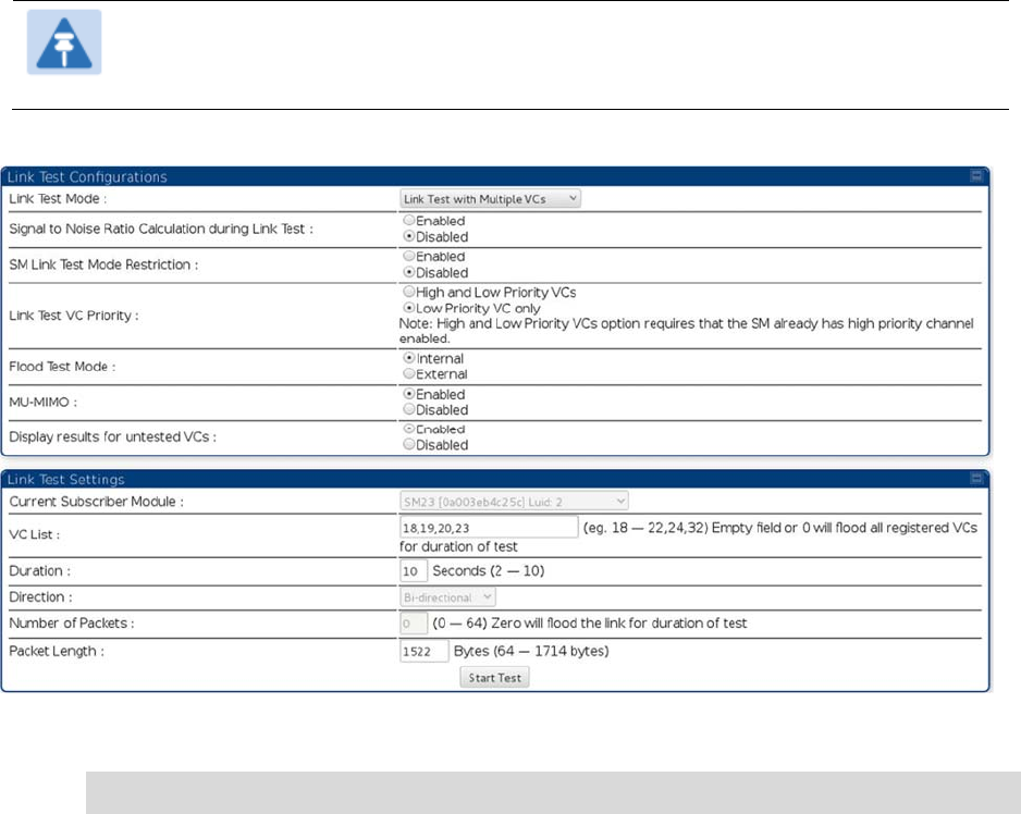
Chapter 8: Tools Using the Link Capacity Test tool
Page 8-22
Link Test with Multiple VCs
Note
The “Link Test with Multiple VCs” Link Capacity Test is supported for PMP 450m Series AP
only.
Figure 184
Link Capacity Test – PMP 450m Series AP
Procedure 32
Performing a Link Capacity Test -
Link Test with Multiple VCs
Link Test Configurations parameters
1
Access the Link Capacity Test tab in the Tools web page of the module.
2
Select Link Test Mode –
Options are:
Link Test with Multiple VCs
,
Link Test without Bridging
,
Link Test with
Bridging
,
Link Test with Bridging
and
MIR, Extrapolated Link Test
All options except for the Link Test with Multiple VCs are available also for the 450 and 450i
APs.
3
Set the
SM Link Test Mode Restriction
attribute to enable or disable. Setting this to
enabled, prevents activation of SM initated link tests.
4
Set
Signal to Noise Ratio Calculation during Link Test
attribute to enable or disable.
5
Set
Link Test VC Priority
attribute to either High and Low Priority VCs or Low Priority VC
only.

Chapter 8: Tools Using the Link Capacity Test tool
Page 8-23
6 Select Flood Test Mode –
Options are: Internal and External
Default is Internal. When set to Internal, packets are sent from AP -> SM over RF. When
set to External, packets will all flow out the Ethernet port.
7 Set MU-MIMO attribute to enable or disable .
Note: The MU-MIMO feature is enabled on the Low Priority VC only
Link Test Settings parameters
6 Select the subscriber module to test using the Current Subscriber Module parameter. Note:
This parameter is not available in BHM.
7 Enter VC List (applicable for PMP 450m AP only)
The Current Subscriber Module and VC List are valid only when selecting Link Test with
Multiple VCs.
Current Subscriber Module: select the VC to perform the link test with
VC list: select a list or range of VCs to include in the link test with multiple VCs
If left blank, all VCs will be included in the link test
8 Type into the Duration field how long (in seconds) the RF link must be tested.
9 Select the Direction – Bi-directional, Uplink Only or Downlink Only.
10 Type into the Number of Packets field a value of 0 to flood the link for the duration of the
test.
11 Type into the Packet Length field a value of 1714 to send 1714-byte packets during the
test.
12 Click the Start Test button.
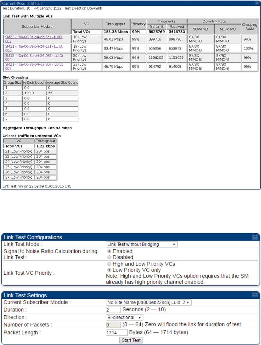
Chapter 8: Tools Using the Link Capacity Test tool
Page 8-24
Figure 185
Link Test with Multiple VCs (1518-byte packet length)
Link Test without Bridging, Link Test with Bridging or Link
Test with Bridging and MIR
Figure 186
Link Capacity Test – PMP 450/450i Series AP
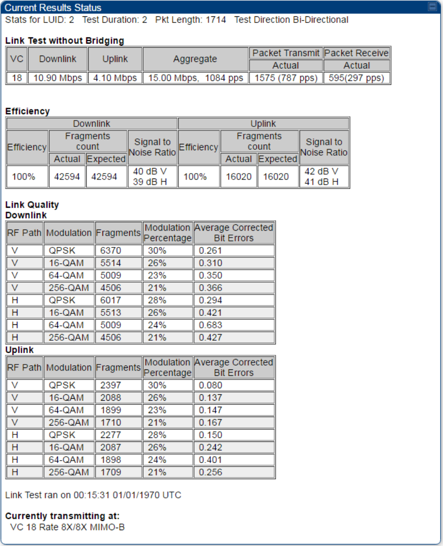
Chapter 8: Tools Using the Link Capacity Test tool
Page 8-25
Refer Link Test with Multiple VCs on page 8-22 for Link Test procedure.
Figure 187 Link Test without Bridging (1714-byte packet length)

Chapter 8: Tools Using the Link Capacity Test tool
Page 8-26
Performing Extrapolated Link Test
The Extrapolated Link Test estimates the link capacity by sending few packets and measuring link quality.
Once the test is initiated, the radio starts session at the lower modulation, 1X, as traffic is passed
successfully across the link, the radio decides to try the next modulation, 2X. This process repeats until it
find best throughput to estimate capacity of link.
Note
It is recommended to run Extrapolated Link Test where the session must have been up and
have traffic present on it in order to get accurate test results. This is essential for the radio to
modulate up to get an accurate measurement.
Running the Extrapolated test just after establishing session will not provide accurate results.
The procedure for performing Extrapolated Link Test is as follows:
Procedure 33 Performing an Extrapolated Link Test
1 Access the Link Capacity Test tab in the Tools web page of the module.
2 Select Link Test Mode Extrapolated Link Test
3 Click the Start Test button.
4 In the Current Results Status block of this tab, view the results of the test.
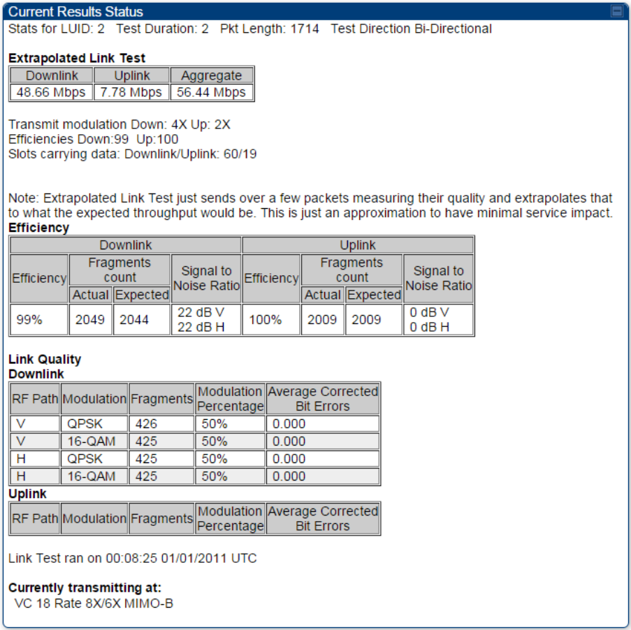
Chapter 8: Tools Using the Link Capacity Test tool
Page 8-27
Figure 188 Extrapolated Link Test results
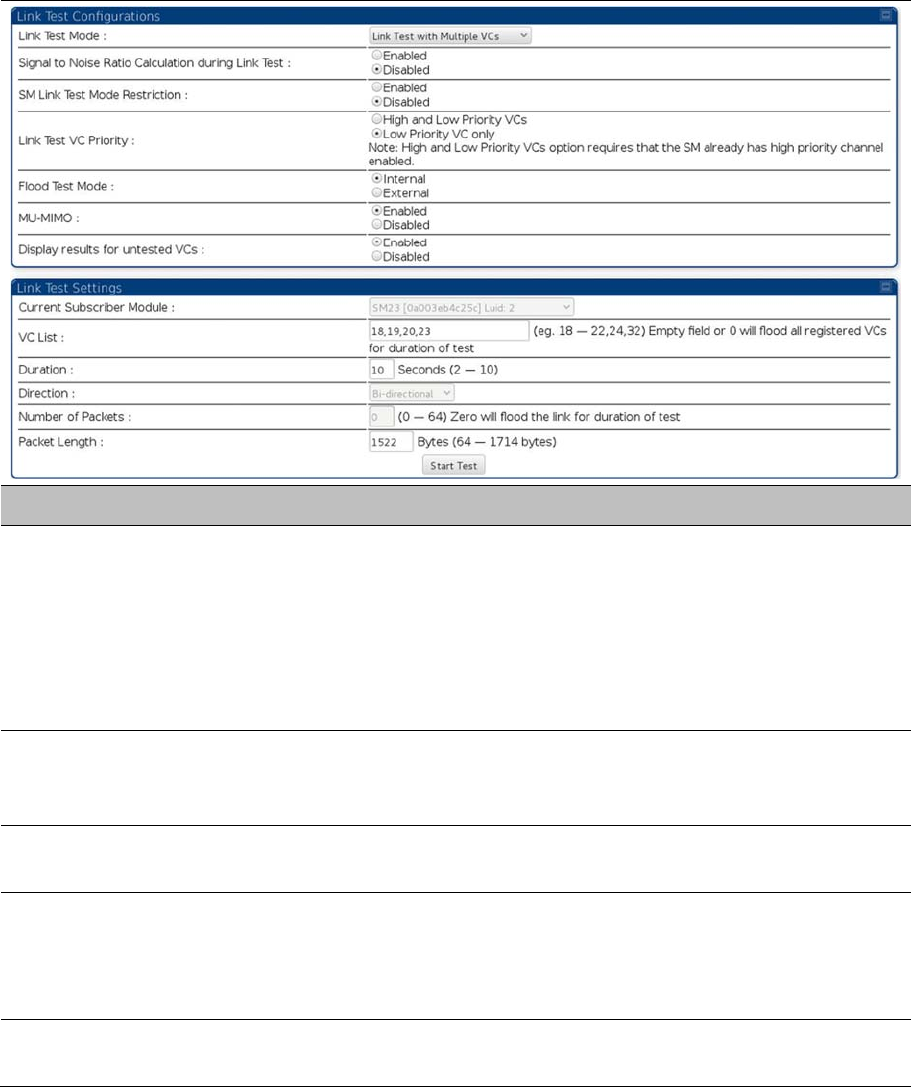
Chapter 8: Tools Using the Link Capacity Test tool
Page 8-28
Link Capacity Test page of AP
The Link Capacity Test page of AP is explained in Table 198.
Table 198
Link Capacity Test page attributes – AP
Attribute Meaning
Link Test Mode
Select Link Test Mode from drop down menu :
Link Test with Multiple VCs (PMP 450m Series AP only)
Link Test without Bridging
Link Test with Bridging
Link Test with Bridging and MIR
Extrapolated Link Test
Signal to Noise Ratio
Calculation during
Link Test
Enable this attribute to display Signal-to-Noise information for the downlink
and uplink when running the link test.
Link Test VC Priority This attribute may be used to enable/disable usage of the high and low
priority virtual channel during the link test.
Flood Test Mode
This field determines whether a packet is sent out of the SM’s Ethernet port
(external) or not (internal).
Note:
This field is applicable only when the “Link Test Mode” field is set to
“Link Test with Multiple VC’s” option.
MU-MIMO This field determines whether the DL flood test packets use MU-MIMO
grouping or not.

Chapter 8: Tools Using the Link Capacity Test tool
Page 8-29
Note: This field is applicable only when the “Link Test Mode” field is set to
“Link Test with Multiple VC’s” option.
Display results for
untested VCs
If “Link test with multiple VC’s” is run and a subset of registered VC’s enters
into the VC List field, then enabling this field produces a table that displays
results for VC’s with traffic which are in session; but not tested as part of the
link test.
Current Subscriber
Module
The SM with which the Link Capacity Test is run. This field is only applicable
for AP (not SM page).
VC List
This field is displayed for PMP 450m Series AP. It is only applicable for “Link
Test with Multiple VCs” Test mode.
Enter VC List (e.g. 18 or above for low priority VCs and 255 or above for high
priority VCs or 0 for all registered VCs) which needs to be used for link test
traffic.
Duration
This field allows operators to configure a specified time for which the
spectrum is scanned. If the entire spectrum is scanned prior to the end of the
configured duration, the analyzer will restart at the beginning of the spectrum.
Direction
Configure the direction of the link test. Specify Downlink or Uplink to run the
test only in the corresponding direction only. Specific Bi-Directional to run
the test in both directions.
Number of Packets The total number of packets to send during the Link Capacity Test. When Link
Test Mode is set to RF Link Test this field is not configurable.
Packet Length The size of the packets in Bytes to send during the Link Capacity Test
Link Capacity Test page of BHM/BHS/SM
The Link Capacity Test page of BHM/BHS is explained in Table 199.
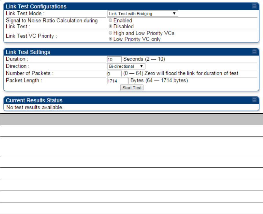
Chapter 8: Tools Using the Link Capacity Test tool
Page 8-30
Table 199 Link Capacity Test page attributes – BHM/BHS
Attribute Meaning
Link Test Mode See Table 198 on page 8-28
Signal to Noise Ratio Calculation
during Link Test See Table 198 on page 8-28
Link Test VC Priority See Table 198 on page 8-28
Duration See Table 198 on page 8-28
Direction See Table 198 on page 8-28
Number of Packets See Table 198 on page 8-28
Packet Length See Table 198 on page 8-28
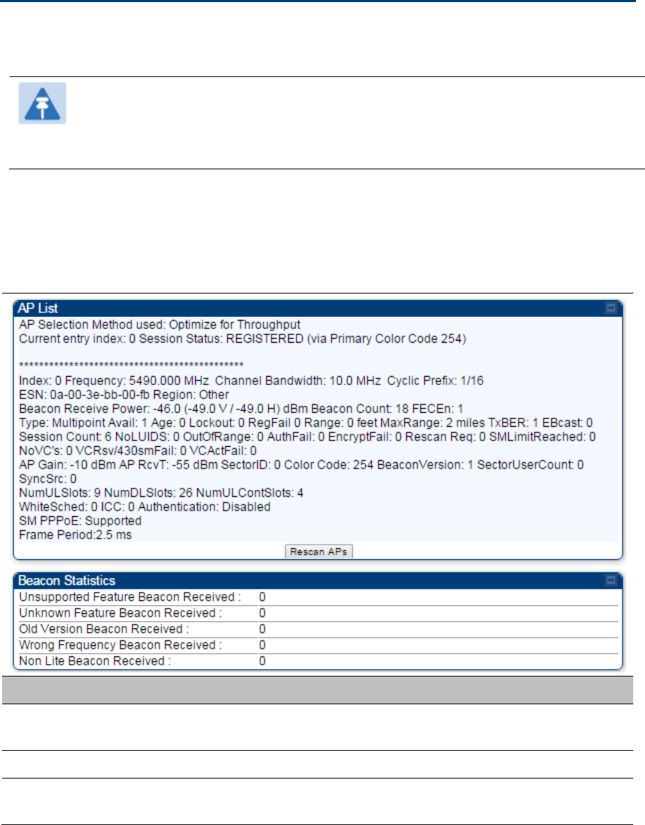
Chapter 8: Tools Using AP Evaluation tool
Page 8-31
Using AP Evaluation tool
The AP Evaluation tab on Tools web page of the SM provides information about the AP that the SM
sees.
Note
The data for this page may be suppressed by the SM Display of AP Evaluation Data
setting in the Configuration > Security tab of the AP.
The AP Eval results can be accessed via SNMP and config file.
AP Evaluation page
The AP Evaluation page of AP is explained in Table 200.
Table 200 AP Evaluation tab attributes - AP
Attribute Meaning
Index This field displays the index value that the system assigns (for only this page)
to the AP where this SM is registered.
Frequency This field displays the frequency that the AP transmits.
Channel Bandwidth The channel size used by the radio for RF transmission. The setting for the
channel bandwidth must match between the AP and the SM.

Chapter 8: Tools Using AP Evaluation tool
Page 8-32
Cyclic Prefix OFDM technology uses a cyclic prefix, where a portion of the end of a symbol
(slot) is repeated at the beginning of the symbol to allow multi-pathing to
settle before receiving the desired data. A 1/16 cyclic prefixes mean that for
every 16 bits of throughput data transmitted, an additional bit is used. The
Cyclic Prefix 1/16 only can be selected at this time.
ESN This field displays the MAC address (electronic serial number) of the AP.
For operator convenience during SM aiming, this tab retains each detected
ESN for up to 15 minutes. If the broadcast frequency of a detected AP
changes during a 15-minute interval in the aiming operation, then a multiple
instance of the same ESN is possible in the list. Eventually, the earlier
instance expires and disappears and the later instance remains to the end of
its interval, but you can ignore the early instance(s) whenever two or more are
present.
Region This field displays the AP’s configured Country Code setting.
Power Level
This field displays the SM’s combined received power level from the AP’s
transmission.
Beacon Count A count of the beacons seen in a given time period.
FECEn This field contains the SNMP value from the AP that indicates whether the
Forward Error Correction feature is enabled.
0: FEC is disabled
1: FEC is enabled
Type Multipoint indicates that the listing is for an AP.
Age This is a counter for the number of minutes that the AP has been inactive. At
15 minutes of inactivity for the AP, this field is removed from the
AP Evaluation tab in the SM.
Lockout This field displays how many times the SM has been temporarily locked out of
making registration attempts.
RegFail This field displays how many registration attempts by this SM failed.
Range This field displays the distance in feet for this link. To derive the distance in
meters, multiply the value of this parameter by 0.3048.
MaxRange This field indicates the configured value for the AP’s Max Range parameter.
TxBER A 1 in this field indicates the AP is sending Radio BER.
Ebcast A 1 in this field indicates the AP or BHM is encrypting broadcast packets. A 0
indicates it is not.
Session Count
This field displays how many sessions the SM (or BHS) has had with the AP
(or BHM). Typically, this is the sum of Reg Count and Re-Reg Count.
However, the result of internal calculation may display here as a value that
slightly differs from the sum.

Chapter 8: Tools Using AP Evaluation tool
Page 8-33
In the case of a multipoint link, if the number of sessions is significantly
greater than the number for other SMs, then this may indicate a link problem
or an interference problem.
NoLUIDs This field indicates how many times the AP has needed to reject a registration
request from a SM because its capacity to make LUID assignments is full.
This then locks the SM out of making any valid attempt for the next
15 minutes. It is extremely unlikely that a non-zero number would be
displayed here.
OutOfRange This field indicates how many times the AP has rejected a registration request
from a SM because the SM is a further distance away than the range that is
currently configured in the AP. This then locks the SM out of making any valid
attempt for the next 15 minutes.
AuthFail This field displays how many times authentication attempts from this SM have
failed in the AP.
EncryptFail This field displays how many times an encryption mismatch has occurred
between the SM and the AP.
Rescan Req This field displays how many times a re-range request has occurred for the
BHM that is being evaluated in the AP Eval page of a BHS.
SMLimitReached This field displays 0 if additional SMs may be registered to the AP. If a 1 is
displayed, the AP will not accept additional SM registrations.
NoVC’s This counter is incremented when the SM is registering to an AP which
determines that no VC resources are available for allocation. This could be a
primary data VC or a high priority data VC.
VCRsvFail This counter is incremented when the SM is registering to an AP which has a
VC resource available for allocation but cannot reserve the resource for
allocation.
VCActFail This counter is incremented when the SM is registering to an AP which has a
VC resource available for allocation and has reserved the VC, but cannot
activate the resource for allocation.
AP Gain This field displays the total external gain (antenna) used by the AP.
RcvT This field displays the AP’s configured receive target for receiving SM
transmissions (this field affects automatic SM power adjust).
Sector ID This field displays the value of the Sector ID field that is provisioned for the
AP.
Color Code This field displays a value from 0 to 254 indicating the AP’s configured color
code. For registration to occur, the color code of the SM and the AP must
match. Color code is not a security feature. Instead, color code is a
management feature, typically for assigning each sector a different color
code.

Chapter 8: Tools Using AP Evaluation tool
Page 8-34
Color code allows you to force a SM to register to only a specific AP, even
where the SM can communicate with multiple APs. The default setting for the
color code value is 0. This value matches only the color code of 0 (not all 255
color codes).
BeaconVersion This field indicates that the beacon is OFDM (value of 1).
Sector User Count This field displays how many SMs are registered on the AP.
NumULHalfSlots This is the number of uplink slots in the frame for this AP.
NumDLHalfSlots This is the number of downlink slots in the frame for this.
NumULContSlots This field displays how many Contention Slots are being used in the uplink
portion of the frame.
WhiteSched Flag to display if schedule whitening is supported via FPGA
ICC This field lists the SMs that have registered to the AP with their Installation
Color Code (ICC),
Primary CC, Secondary CC or Tertiary CC.
SM PPPoE This filed provides information to the user whether the SM is supporting
PPPoE or not.
Frame Period This field displays the configured Frame Period of the radio.
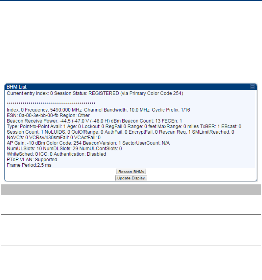
Chapter 8: Tools Using BHM Evaluation tool
Page 8-35
Using BHM Evaluation tool
The BHM Evaluation tab on Tools web page of the BHS provides information about the BHM that the
BHS sees.
BHM Evaluation page of BHS
The BHM Evaluation page of BHS is explained in Table 201.
Table 201 BHM Evaluation tab attributes - BHS
Attribute Meaning
Index This field displays the index value that the system assigns (for only this page)
to the BHM where this BHS is registered.
Frequency This field displays the frequency that the BHM transmits.
Channel Bandwidth The channel size used by the radio for RF transmission. The setting for the
channel bandwidth must match between the BHM and the BHS.
Cyclic Prefix OFDM technology uses a cyclic prefix, where a portion of the end of a symbol
(slot) is repeated at the beginning of the symbol to allow multi-pathing to
settle before receiving the desired data. A 1/16 cyclic prefixes mean that for
every 16 bits of throughput data transmitted, an additional bit is used.

Chapter 8: Tools Using BHM Evaluation tool
Page 8-36
ESN This field displays the MAC address (electronic serial number) of the BHM.
For operator convenience during BHS aiming, this tab retains each detected
ESN for up to 15 minutes. If the broadcast frequency of a detected BHM
changes during a 15-minute interval in the aiming operation, then a multiple
instance of the same ESN is possible in the list. Eventually, the earlier
instance expires and disappears and the later instance remains to the end of
its interval, but you can ignore the early instance(s) whenever two or more are
present.
Region This field displays the BHM’s configured Country Code setting.
Power Level
This field displays the BHS’s combined received power level from the BHM’s
transmission.
Beacon Count A count of the beacons seen in a given time period.
FECEn This field contains the SNMP value from the BHM that indicates whether the
Forward Error Correction feature is enabled.
0: FEC is disabled
1: FEC is enabled
Type Multipoint indicates that the listing is for a BHM.
Age This is a counter for the number of minutes that the BHM has been inactive.
At 15 minutes of inactivity for the BHS, this field is removed from the BHM
Evaluation tab in the BHS.
Lockout This field displays how many times the BHS has been temporarily locked out
of making registration attempts.
RegFail This field displays how many registration attempts by this BHS failed.
Range This field displays the distance in feet for this link. To derive the distance in
meters, multiply the value of this parameter by 0.3048.
MaxRange This field indicates the configured value for the AP’s Max Range parameter.
TxBER A 1 in this field indicates the BHM is sending Radio BER.
Ebcast A 1 in this field indicates the BHM is encrypting broadcast packets. A 0
indicates it is not.
Session Count
This field displays how many sessions the BHS has had with the BHM.
Typically, this is the sum of Reg Count and Re-Reg Count. However, the
result of internal calculation may display here as a value that slightly differs
from the sum.
In the case of a multipoint link, if the number of sessions is significantly
greater than the number for other BHS’s, then this may indicate a link
problem or an interference problem.

Chapter 8: Tools Using BHM Evaluation tool
Page 8-37
NoLUIDs This field indicates how many times the BHM has needed to reject a
registration request from a BHS because its capacity to make LUID
assignments is full. This then locks the BHS out of making any valid attempt
for the next 15 minutes. It is extremely unlikely that a non-zero number would
be displayed here.
OutOfRange This field indicates how many times the BHM has rejected a registration
request from a BHS because the BHS is a further distance away than the
range that is currently configured in the BHM. This then locks the BHS out of
making any valid attempt for the next 15 minutes.
AuthFail This field displays how many times authentication attempts from this SM have
failed in the BHM.
EncryptFail This field displays how many times an encryption mismatch has occurred
between the BHS and the BHM.
Rescan Req This field displays how many times a re-range request has occurred for the
BHM that is being evaluated in the BHM Eval page of a BHM.
SMLimitReached This field displays 0 if additional BHSs may be registered to the BHM. If a 1 is
displayed, the BHM will not accept additional BHS registrations.
NoVC’s This counter is incremented when the BHS is registering to a BHM which
determines that no VC resources are available for allocation. This could be a
primary data VC or a high priority data VC.
VCRsvFail This counter is incremented when the BHS is registering to a BHM which has
a VC resource available for allocation but cannot reserve the resource for
allocation.
VCActFail This counter is incremented when the BHS is registering to a BHM which has
a VC resource available for allocation and has reserved the VC, but cannot
activate the resource for allocation.
AP Gain This field displays the total external gain (antenna) used by the BHM.
RcvT This field displays the AP’s configured receive target for receiving BHS
transmissions (this field affects automatic BHS power adjust).
Sector ID This field displays the value of the Sector ID field that is provisioned for the
BHM.
Color Code This field displays a value from 0 to 254 indicating the BHM’s configured color
code. For registration to occur, the color code of the BHS and the BHM must
match. Color code is not a security feature. Instead, color code is a
management feature, typically for assigning each sector a different color
code.
Color code allows you to force a BHS to register to only a specific BHM, even
where the BHS can communicate with multiple BHMs. The default setting for
the color code value is 0. This value matches only the color code of 0 (not all
255 color codes).

Chapter 8: Tools Using BHM Evaluation tool
Page 8-38
BeaconVersion This field indicates that the beacon is OFDM (value of 1).
Sector User Count This field displays how many BHS’s are registered on the BHM.
NumULHalfSlots This is the number of uplink slots in the frame for this BHM.
NumDLHalfSlots This is the number of downlink slots in the frame for this.
NumULContSlots This field displays how many Contention Slots are being used in the uplink
portion of the frame.
WhiteSched Flag to display if schedule whitening is supported via FPGA
ICC This field lists the BHSs that have registered to the BHM with their Installation
Color Code (ICC),
Primary CC, Secondary CC or Tertiary CC.
SM PPPoE This filed provides information to the user whether the BHS is supporting
PPPoE or not.
Frame Period This field displays the configured Frame Period of the radio.

Chapter 8: Tools Using the OFDM Frame Calculator tool
Page 8-39
Using the OFDM Frame Calculator tool
The first step to avoid interference in wireless systems is to set all APs/BHMs to receive timing from a
synchronization source (Cluster Management Module, or Universal Global Positioning System). This
ensures that the modules are in sync and start transmitting at the same time each frame.
The second step to avoid interference is to configure parameters on all APs/BHMs of the same frequency
band in proximity such that they have compatible transmit/receive ratios (all stop transmitting each frame
before any start receiving). This avoids the problem of one AP/BHM attempting to receive the signal from
a distant SM/BHS while a nearby AP transmits, which could overpower that signal.
The following parameters on the AP determine the transmit/receive ratio:
Max Range
Frame Period
Downlink Data percentage
(reserved) Contention Slots
If OFDM (PMP 430, PMP 450, PTP 230) and FSK (PMP 1x0) APs/BHMs of the same frequency band are
in proximity, or if APs/BHMs set to different parameters (differing in their Max Range values, for example),
then operator must use the Frame Calculator to identify compatible settings.
The frame calculator is available on the Frame Calculator tab of the Tools web page. To use the Frame
Calculator, type various configurable parameter values into the calculator for each proximal AP and then
record the resulting AP/BHM Receive Start value. Next vary the Downlink Data percentage in each
calculation and iterate until the calculated AP/BHM Receive Start for all collocated AP/BHMs where the
transmit end does not come before the receive start.
The calculator does not use values in the module or populate its parameters. It is merely a convenience
application that runs on a module. For this reason, you can use any FSK module (AP, SM, BHM, BHS) to
perform FSK frame calculations for setting the parameters on an FSK AP and any OFDM module (AP,
SM, BHM, BHS) to perform OFDM frame calculations for setting the parameters on an OFDM AP/BHM.
For more information on PMP/PTP 450 Platform co-location, see
http://www.cambiumnetworks.com/solution-papers
The co-location is also supported for 900 MHz PMP 450i APs (OFDM) and PMP 100 APs (FSK). Please
refer Co-location of PMP 450 and PMP 100 systems in the 900 MHz band and migration
recommendations document for details.
Caution
APs/BHMs that have slightly mismatched transmit-to-receive ratios and low levels of data
traffic may see little effect on throughput. A system that was not tuned for co-location may
work fine at low traffic levels, but encounter problems at higher traffic levels. The
conservative practice is to tune for co-location before traffic ultimately increases. This
prevents problems that occur as sectors are built.
The OFDM Frame Calculator page is explained in Table 202.
Chapter 8: Tools Using the OFDM Frame Calculator tool
Page 8-40
Table 202
OFDM Frame Calculator page attributes
Attribute Meaning
Link Mode For AP to SM frame calculations, select
Multipoint Link
For BHM to BHS frame calculations, select
Point-To-Point Link
Platform Type
AP/BHM
Use the drop-down list to select the hardware series (board type) of the
AP/BHM.
Platform Type
SM/BHS
Use the drop-down list to select the hardware series (board type) of the
SM/BHS.
Channel Bandwidth Set this to the channel bandwidth used in the AP/BHM.
Cyclic Prefix Set this to the cyclic prefix used in the AP/BHM.
Max Range Set to the same value as the
Max Range
parameter is set in the AP(s) or
BHM(s).

Chapter 8: Tools Using the OFDM Frame Calculator tool
Page 8-41
Frame Period Set to the same value as the Frame Period parameter is set in the AP(s) or
BHM(s).
Downlink Data Initially set this parameter to the same value that the AP/BHM has for its
Downlink Data parameter (percentage). Then, use the Frame Calculator tool
procedure as described in Using the Frame Calculator on page 8-42, you will
vary the value in this parameter to find the proper value to write into the
Downlink Data parameter of all APs or BHMs in the cluster.
PMP 450 Platform Family APs or BHMs offer a range of 15% to 85% and
default to 75%. The value that you set in this parameter has the following
interaction with the value of the Max Range parameter (above):
The default Max Range value is 5 miles and, at that distance, the maximum
Downlink Data value (85% in PMP 450 Platform) is functional.
Contention Slots This field indicates the number of (reserved) Contention Slots configured by
the operator. Set this parameter to the value of the Contention Slot
parameter is set in the APs or BHMs.
SM/BHS One Way Air
Delay
This field displays the time in ns (nano seconds), that a SM/BHS is away from
the AP/BHM.
The Calculated Frame Results display several items of interest:
Table 203 OFDM Calculated Frame Results attributes
Attribute Meaning
Modulation The type of radio modulation used in the calculation (OFDM for 450 Platform
Family)
Total Frame Bits The total number of bits used in the calculated frames
Data Slots (Down/Up) This field is based on the Downlink Data setting. For example, a result within
the typical range for a Downlink Data setting of 75% is 61/21, meaning 61
data slots down and 21 data slots up.
Contention Slots This field indicates the number of (reserved) Contention Slots configured by
the operator.
Air Delay for Max
Range
This is the roundtrip air delay in bit times for the Max Range value set in the
calculator
Approximate distance
for Max Range
The Max Range value used for frame calculation
AP Transmit End In bit times, this is the frame position at which the AP/BHM ceases
transmission.
AP Receive Start In bit times, this is the frame position at which the AP/BHM is ready to receive
transmission from the SM/BHS.

Chapter 8: Tools Using the OFDM Frame Calculator tool
Page 8-42
AP Receive End In bit times, this is the frame position at which the AP/BHM will cease
receiving transmission from the SM/BHS.
SM Receive End In bit times, this is the frame position at which the SM/BHS will cease
receiving transmission from the AP/BHM.
SM Transmit Start In bit times, this is the frame position at which the SM/BHS starts the
transmission.
SM One Way Air
Delay
This filed displays the time in ns, that SM/BHS is away from the AP/BHM.
SM Approximate
distance
This field displays an approximate distance in miles (feet) that the SM/BHS is
away from the AP/BHM.
To use the Frame Calculator to ensure that all APs or BHMs are configured to transmit and receive at the
same time, follow the procedure below:
Procedure 34 Using the Frame Calculator
1 Populate the OFDM Frame Calculator parameters with appropriate values as described
above.
2 Click the Calculate button.
3 Scroll down the tab to the Calculated Frame Results section
4 Record the value of the AP Receive Start field
5 Enter a parameter set from another AP in the system – for example, an AP in the same
cluster that has a higher Max Range value configured.
6 Click the Calculate button.
7 Scroll down the tab to the Calculated Frame Results section
8 If the recorded values of the AP Receive Start fields are within 150 bit times of each other,
skip to step 10.
If the recorded values of the AP Receive Start fields are not within 150 bit times of each
other, modify the Downlink Data parameter until the calculated results for AP Receive
Start are within 300 bit time of each other, if possible, 150 bit time.
10 Access the Radio tab in the Configuration web page of each AP in the cluster and change
its Downlink Data parameter (percentage) to the last value that was used in the Frame
Calculator.
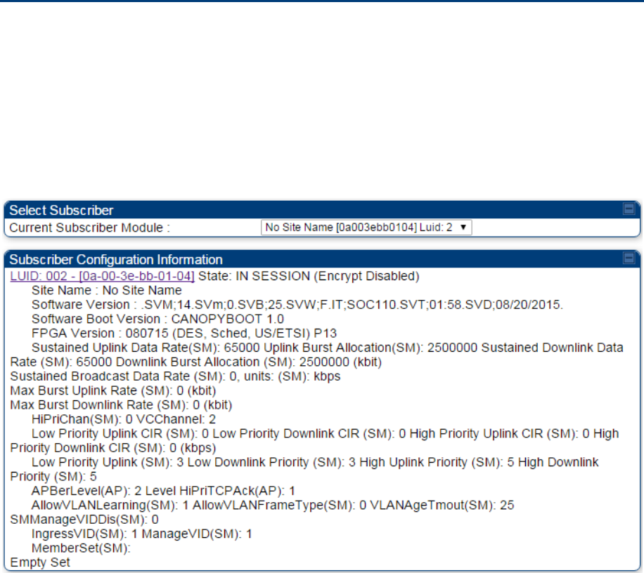
Chapter 8: Tools Using the Subscriber Configuration tool
Page 8-43
Using the Subscriber Configuration tool
The Subscriber Configuration page in the Tools page of the AP displays:
The current values whose control may be subject to the setting in the Configuration Source
parameter.
An indicator of the source for each value.
This page may be referenced for information on how the link is behaving based on where the SM is
retrieving certain QoS and VLAN parameters.
Figure 189 SM Configuration page of AP
The AP displays one of the following for the configuration source:
(SM) – QoS/VLAN parameters are derived from the SM’s settings
(APCAP) – QoS/VLAN parameters are derived from the AP’s settings, including any keyed capping
(for radios capped at 4 Mbps, 10 Mbps, or 20 Mbps)
(D) – QoS/VLAN parameters are retrieved from the device, due to failed retrieval from the AAA or
WM server.
(AAA) – QoS/VLAN parameters are retrieved from the RADIUS server
(BAM) – QoS/VLAN parameters are retrieved from a WM BAM server

Chapter 8: Tools Using the Link Status tool
Page 8-44
Using the Link Status tool
The Link Status Tool displays information about the most-recent Link Test initiated on the SM or BHS.
Link Tests initiated from the AP or BHM are not included in the Link Status table. This table is useful for
monitoring link test results for all SMs or BHS in the system.
The Link Status table is color coded to display health of link between AP/BHM and SM/BHS. The current
Modulation Level Uplink/Downlink is chosen to determine link health and color coded accordingly.
Uplink/Downlink Rate Column will be color coded using current Rate as per the table below:
Table 204 Color code versus uplink/downlink rate column
Actual Rate 1x 2x 3x 4x 6x 8x
SISO RED ORANGE GREEN BLUE NA NA
MIMO-A RED ORANGE GREEN BLUE NA NA
MIMO B NA RED NA ORANGE GREEN BLUE
Link Status – AP/BHM
The current Uplink Rate (both low and high VC) for each SM or BHS in Session in now available on AP or
BHM Link Status Page.
The Link Status tool results include values for the following fields for AP/BHM.
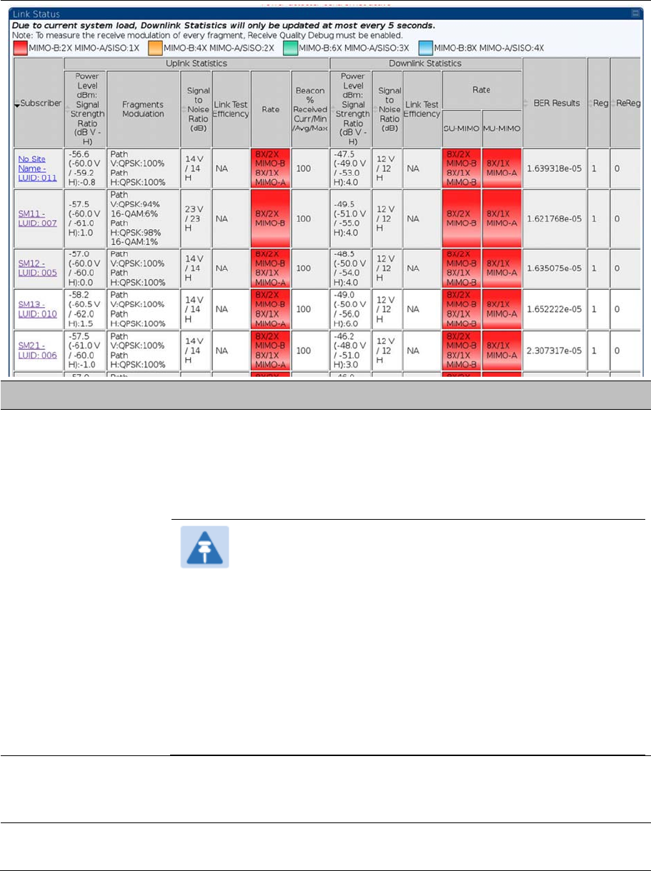
Chapter 8: Tools Using the Link Status tool
Page 8-45
Table 205
Link Status page attributes – AP/BHM
Attribute Meaning
Subscriber This field displays the LUID (logical unit ID), MAC address and Site Name of
the SM. As each SM registers to the AP, the system assigns an LUID of 2 or
a higher unique number to the SM. If a SM loses registration with the AP and
then regains registration, the SM will retain the same LUID.
Note
The LUID associated is lost when a power cycle of the AP
occurs.
Both the LUID and the MAC are hot links to open the interface
to the SM. In some instances, depending on network activity
and network design, this route to the interface yields a blank
web page. If this occurs, refresh your browser view.
Site Name indicates the name of the SM. You can assign or
change this name on the Configuration web page of the SM.
This information is also set into the
sysName
SNMP MIB-II
object and can be polled by an SNMP management server.
Uplink Statistics -
Power Level: Signal
Strength Ratio
This field represents the combined received power level at the AP/BHM as
well as the ratio of horizontal path signal strength to vertical path signal
strength.
Uplink Statistics –
Fragments Modulation
This field represents the percentage of fragments received at each
modulation state, per path (polarization).

Chapter 8: Tools Using the Link Status tool
Page 8-46
Uplink Statistics –
Signal to Noise Ratio
This field represents the signal to noise ratio for the uplink (displayed when
parameter Signal to Noise Ratio Calculation during Link Test is enabled)
expressed for both the horizontal and vertical channels.
Uplink Statistics – Link
Test Efficiency
This field displays the efficiency of the radio link, expressed as a percentage,
for the radio uplink.
Downlink Statistics –
Beacon % Received
Curr/Min/Max/Avg
This field displays a count of beacons received by the SM in percentage. This
value must be between 99-100%. If it is lower than 99%, it indicates a
problematic link. This statistic is updated every 16 seconds.
Downlink Statistics –
Power Level: Signal
Strength Ratio
This field represents the received power level at the SM/BHS as well as the
ratio of horizontal path signal strength to vertical path signal strength at the
SM/BHS.
Downlink Statistics –
Signal to Noise Ratio
This field represents the signal to noise ratio for the downlink (displayed when
parameter Signal to Noise Ratio Calculation during Link Test is enabled)
expressed for both the horizontal and vertical channels.
Downlink Statistics –
Link Test Efficiency
This field displays the efficiency of the radio link, expressed as a percentage,
for the radio downlink.
Downlink Statistics –
SU-MIMO Rate
The SU-MIMO rate applies to all AP platforms.
For 450m, this field indicates the rate being used for symbols where this
particular VC is not being MU-MIMO grouped with other SMs.
For 450 and 450i platforms, there is no grouping and this field indicates the
modulation rate for all symbols.
Downlink Statistics –
MU-MIMO Rate
The MU-MIMO rate applies only to the 450m AP. This field indicates the
modulation rate used for symbols where this particular low priority VC is MU-
MIMO scheduled by grouping it in the same slot with other low priority VC’s.
BER Results This field displays the over-the-air Bit Error Rates for each downlink. (The
ARQ [Automatic Resend 8-46equest] ensures that the transport BER [the
BER seen end-to-end through a network] is essentially zero.) The level of
acceptable over-the-air BER varies, based on operating requirements, but a
reasonable value for a good link is a BER of 1e-4 (1 x 10⁻⁴) or better,
approximately a packet resend rate of 5%.
BER is generated using unused bits in the downlink. During periods of peak
load, BER data is not updated as often, because the system puts priority on
transport rather than on BER calculation.
Reg Requests A Reg Requests count is the number of times the SM/BHS registered after
the AP/BHM determined that the link had been down.
If the number of sessions is significantly greater than the number for other
SMs/BHS, then this may indicate a link problem (check mounting, alignment,
receive power levels) or an interference problem (conduct a spectrum scan).
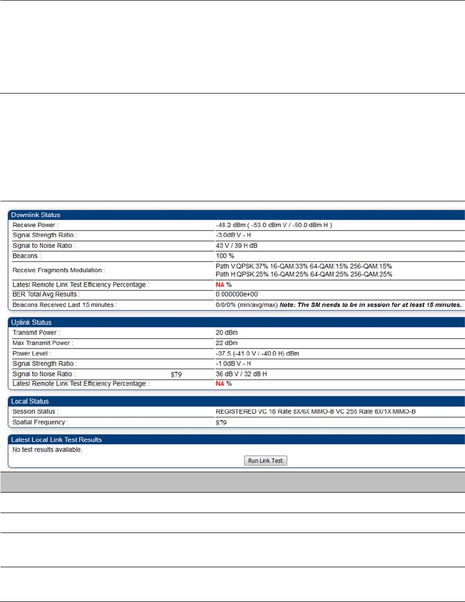
Chapter 8: Tools Using the Link Status tool
Page 8-47
ReReg Requests A ReReg Requests count is the number of times the AP/BHM received a
SM/BHS registration request while the AP/BHM considered the link to be still
up (and therefore did not expect registration requests).
If the number of sessions is significantly greater than the number for other
SMs/BHS, then this may indicate a link problem (check mounting, alignment,
receive power levels) or an interference problem (conduct a spectrum scan).
Link Status – SM/BHS
The Link Status tool of SM/BHS displays Downlink Status and Uplink Status information.
Table 206
Link Status page attributes – SM/BHS
Attribute Meaning
Downlink Status
Receive Power This field lists the current combined receive power level, in dBm.
Signal Strength Ratio This field displays the difference of the Vertical path received signal power to
the Horizontal path received signal power for downlink.
Signal to Noise Ratio This field lists the current signal-to-noise level, an indication of the separation
of the received power level vs. noise floor for downlink.
Chapter 8: Tools Using the Link Status tool
Page 8-48
Beacons Displays a count of beacons received by the SM in percentage. This value
must be typically between 99-100%. If lower than 99%, it indicates a
problematic link. This statistic is updated every 16 seconds.
Received Fragments
Modulation
This field represents the percentage of fragments received at each
modulation state, per path (polarization)
Latest Remote Link
Test Efficiency
Percentage
This field is not applicable.
BER Total Avg
Results
This field displays the over-the-air average Bit Error Rates (BER) for
downlink.
Beacons Received
Last 15 minutes
The beacon count on the SM can be used to estimate the interference in the
channel. The min/avg/max beacon percentage displayed based on this value
for the last 15 mins.
Uplink Status
Transmit Power This field displays the current combined transmit power level, in dBm.
Max Transmit Power This field displays the maximum transmit power of SM.
Power Level This field indicates the combined power level at which the SM is set to
transmit, based on the Country Code and Antenna Gain settings.
Signal Strength Ratio This field displays the difference of the Vertical path received signal power to
the Horizontal path received signal power for uplink.
Signal to Noise Ratio This field lists the current signal-to-noise level, an indication of the separation
of the received power level vs. noise floor for uplink.
Latest Remote Link
Test Efficiency
Percentage
This field is not applicable.
Session Status This field displays the current state, Virtual channel, high-priority/ low priority
channel rate adaptation and MIMO-A/MIMO-B/SISO status of SM.
Spatial Frequency This filed displays the spatial frequency value of the VC or SM.
Run Link Test
See Exploratory Test section of Performing Extrapolated Link Test on page 8-
26
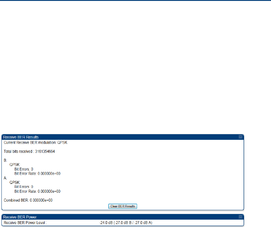
Chapter 8: Tools Using BER Results tool
Page 8-49
Using BER Results tool
Radio BER data represents bit errors at the RF link level. Due to CRC checks on fragments and packets
and ARQ (Automatic Repeat 8-49equest), the BER of customer data is essentially zero. Radio BER gives
one indication of link quality. Other important indications to consider includes the received power level,
signal to noise ratio and link tests.
BER is only instrumented on the downlink and is displayed on the BER Results tab of the Tools page in
any SM. Each time the tab is clicked, the current results are read and counters are reset to zero.
The BER Results tab can be helpful in troubleshooting poor link performance.
The link is acceptable if the value of this field is less than 10−4. If the BER is greater than 10−4, re-evaluate
the installation of both modules in the link.
The BER test signal is broadcast by the AP/BHM (and compared to the expected test signal by the
SM/BHS) only when capacity in the sector allows it. This signal is the lowest priority for AP/BHM
transmissions.
Figure 190 BER Results tab of the SM
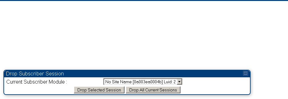
Chapter 8: Tools Using the Sessions tool
Page 8-50
Using the Sessions tool
The PMP 450 Platform Family AP has a tab Sessions under the Tools category which allows operators
to drop one or all selected SM sessions and force a SM re-registration. This operation is useful to force
QoS changes for SMs without losing AP logs or statistics. This operation may take 5 minutes to regain all
SM registrations.
Figure 191 Sessions tab of the AP
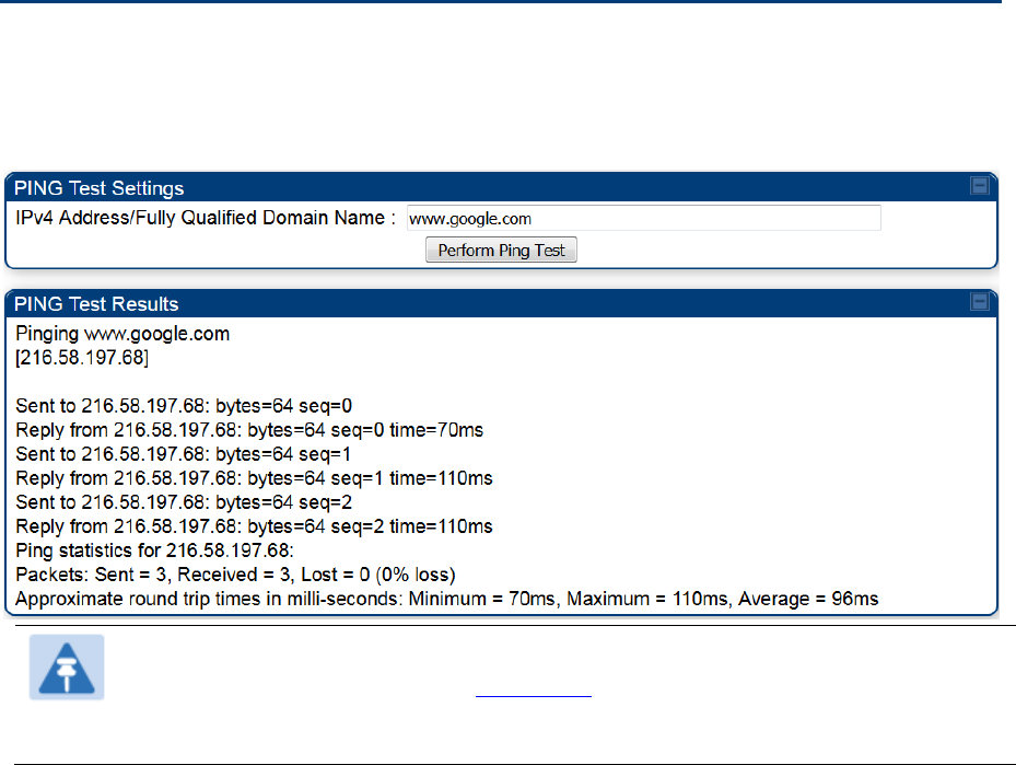
Chapter 8: Tools Using the Ping Test tool
Page 8-51
Using the Ping Test tool
The PMP 450 Platform Family AP has a tab Ping Test under the Tools category which allows users to
check the accessibility of the given IP V4 address or a valid domain name
Figure 192 Ping Test tab of the AP
Note
When a domain name (for example, www.google.com) is used for ping test, make sure that
Preferred DNS Server and Alternate DNS Server parameters are configured in the
Configuration > IP tab of the AP.

Page 9-1
Chapter 9: Operation
This chapter provides instructions for operators of the 450 Platform Family wireless Ethernet Bridge. The
following topics are described in this chapter:
System information on page 9-2
o Viewing General Status on page 9-2
o Viewing Session Status on page 9-20
o Viewing Remote Subscribers on page 9-29
o Interpreting messages in the Event Log on page 9-29
o Viewing the Network Interface on page 9-32
o Viewing the Layer 2 Neighbors on page 9-32
System statistics on page 9-33
o Viewing the Scheduler statistics on page 9-33
o Viewing list of Registration Failures statistics on page 9-35
o Interpreting Bridging Table statistics on page 9-37
o Interpreting Translation Table statistics on page 9-37
o Interpreting Ethernet statistics on page 9-38
o Interpreting RF Control Block statistics on page 9-41
o Interpreting VLAN statistics on page 9-2
o Interpreting Data VC statistics on page 9-4
o Interpreting Throughput statistics on page 9-6
o Interpreting Overload statistics on page 9-9
o Interpreting DHCP Relay statistics on page 9-10
o Interpreting Filter statistics on page 9-12
o Viewing ARP statistics on page 9-13
o Viewing NAT statistics on page 9-13
o Viewing NAT DHCP Statistics on page 9-15
o Interpreting Sync Status statistics on page 9-16
o Interpreting PPPoE Statistics for Customer Activities on page 9-17
o Interpreting Bridge Control Block statistics on page 9-19
o Interpreting Pass Through Statistics on page 9-22
o Interpreting SNMPv3 Statistics on page 9-23
o Interpreting syslog statistics on page 9-25
o Interpreting Frame Utilization statistics on page 9-25
Radio Recovery on page 9-36

Chapter 9: Operation System information
Page 9-2
System information
This section describes how to use the summary and status pages to monitor the status of the Ethernet
ports and wireless link.
Viewing General Status on page 9-2
Viewing Session Status on page 9-20
Viewing Remote Subscribers on page 9-29
Interpreting messages in the Event Log on page 9-29
Viewing the Network Interface on page 9-32
Viewing the Layer 2 Neighbors on page 9-32
Viewing General Status
The General Status tab provides information on the operation of this AP/BHM and SM/BHS. This is the
page that opens by default when you access the GUI of the radio.
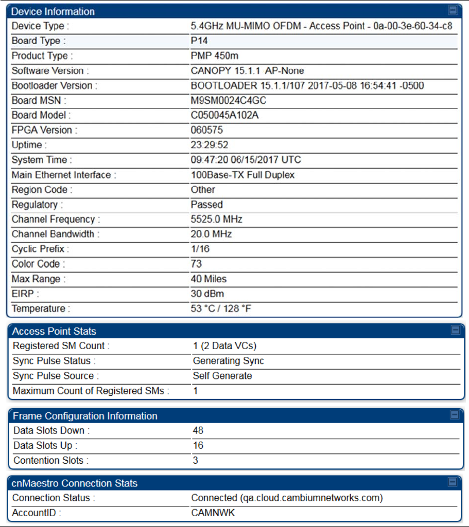
Chapter 9: Operation System information
Page 9-3
General Status page of AP
The
General Status
page of PMP 450m AP is explained in Table 207
The
General Status
page of PMP 450/450i AP is explained in Table 208.
Table 207
General Status page attributes – PMP 450m AP
Chapter 9: Operation System information
Page 9-4
Attribute Meaning
Device Type This field indicates the type of the module. Values include the frequency band
of the device, its module type and its MAC address.
Board Type This field indicates the series of hardware.
Software Version This field indicates the system release, the time and date of the release and
whether communications involving the module are secured by DES or AES
encryption. If you request technical support, provide the information from this
field.
Bootloader Version This field indicates the version of Uboot running on the 450m AP platform.
Product Type The field indicates model number of 450m device. The 450m Series has two
model variants.
PMP 450m: This model works in SU-MIMO mode which is default
“limited” mode. The MU-MIMO license can be purchased from Cambium
Networks and applied.
MU-MIMO: This model works in MU-MIMO mode.
Board MSN This field indicates the Manufacture’s Serial number. A unique serial number
assigned to each radio at the factory for inventory and quality control.
FPGA Version This field indicates the version of the field-programmable gate array (FPGA)
on the module. If you request technical support, provide the value of this field.
Uptime This field indicates how long the module has operated since power was
applied.
System Time This field provides the current time. If the AP is connected to a CMM4, then
this field provides GMT (Greenwich Mean Time). Any SM that registers to the
AP inherits the system time.
Last NTP Time
Update
This field displays when the AP last used time sent from an NTP server. If the
AP has not been configured in the Time tab of the Configuration page to
request time from an NTP server, then this field is populated by 00:00:00
00/00/00.
Main Ethernet
Interface
This field indicates the speed and duplex state of the Ethernet interface to the
AP.

Chapter 9: Operation System information
Page 9-5
Aux Ethernet Interface This field displays Aux Ethernet Data and PoE-out interface enable/disable
status. It is not supported in current release of PMP 450m Seriea AP.
Region Code A parameter that offers multiple fixed selections, each of which automatically
implements frequency band range for the selected region. Units shipped to
regions other than restrictions the United States must be configured with the
corresponding Region Code to comply with local regulatory requirements.
Regulatory
This field indicates whether the configured Country Code and radio
frequency are compliant with respect to their compatibility. 450 Platform
Family products shipped to the United States is locked to a Country Code
setting of “United States”. Units shipped to regions other than the United
States must be configured with the corresponding Country Code to comply
with local regulatory requirements.
Channel Frequency This field indicates the current operating center frequency, in MHz.
Channel Bandwidth This field indicates the current size of the channel band used for radio
transmission.
Cyclic Prefix OFDM technology uses a cyclic prefix, where a portion of the end of a symbol
(slot) is repeated at the beginning of the symbol to allow multi-pathing to
settle before receiving the desired data. A 1/16 cyclic prefix means that for
every 16 bits of throughput data transmitted, an additional bit is used.
Frame Period This field indicates the current Frame Period setting of the radio in ms.
Color Code This field displays a value from 0 to 254 indicating the AP’s configured color
code. For registration to occur, the color code of the SM and the AP must
match. Color code is not a security feature. Instead, color code is a
management feature, typically for assigning each sector a different color
code.
Color code allows you to force a SM to register to only a specific AP, even
where the SM can communicate with multiple APs. The default setting for the
color code value is 0. This value matches only the color code of 0 (not all 255
color codes).
Max Range This field indicates the setting of the Max Range parameter, which contributes
to the way the radio transmits. Verify that the Max Range parameter is set to
a distance slightly greater than the distance between the AP and the furthest
SM that must register to this AP.
EIRP This field indicates the combined power level at which the AP will transmit,
based on the Country Code.
Temperature This field indicates the current operating temperature of the device board.
Registered SM Count This field indicates how many SMs are registered to the AP.
Sync Pulse Status
This field indicates the status of synchronization as follows:
Generating Sync indicates that the module is set to generate the sync pulse.

Chapter 9: Operation System information
Page 9-6
Receiving Sync indicates that the module is set to receive a sync pulse from
an outside source and is receiving the pulse.
No Sync Since Boot up / ERROR: No Sync Pulse indicates that the module
is set to receive a sync pulse from an outside source and is not receiving the
pulse.
Note
When this message is displayed, the AP transmitter is turned off
to avoid self-interference within the system.
Sync Pulse Source This field indicates the status of the synchronization source:
Searching indicates that the unit is searching for a GPS fix
Timing Port/UGPS indicates that the module is receiving sync via the timing
AUX/SYNC timing port
Power Port indicates that the module is receiving sync via the power port
(Ethernet port).
On-board GPS indicates that the module is receiving sync via the unit’s
internal GPS module
Maximum Count of
Registered SMs
This field displays the largest number of SMs that have been simultaneously
registered in the AP since it was last rebooted. This count can provide some
insight into sector history and provide comparison between current and
maximum SM counts at a glance.
Data Slots Down This field indicates the number of frame slots that are designated for use by
data traffic in the downlink (sent from the AP to the SM). The AP calculates
the number of data slots based on the Max Range, Downlink Data and
(reserved) Contention Slots configured by the operator.
Data Slots Up
This field indicates the number of frame slots that are designated for use by
data traffic in the uplink (sent from the SM to the AP). The AP calculates the
number of data slots based on the Max Range, Downlink Data and (reserved)
Contention Slots configured by the operator.
Contention Slots This field indicates the number of (reserved) Contention Slots configured by
the operator. See Contention slots on page7-176.
Connection Status This field indicates the device connectivity to cnMaestro (Cambium’s cloud-
based network management system).
Account ID This field shows Account ID which is registered with Cambium Networks and
it allows operator to manage devices using cnMaestro.
Site Name This field indicates the name of the physical module. You can assign or
change this name in the SNMP tab of the AP Configuration page. This
information is also set into the sysName SNMP MIB-II object and can be
polled by an SNMP management server.

Chapter 9: Operation System information
Page 9-7
Site Contact This field indicates contact information for the physical module. You can
provide or change this information in the SNMP tab of the AP Configuration
page. This information is also set into the sysName SNMP MIB-II object and
can be polled by an SNMP management server.
Site Location This field indicates site information for the physical module. You can provide
or change this information in the SNMP tab of the AP Configuration page.
MU-MIMO Mode This field displays information about MU-MIMO mode. If AP is keyed as MU-
MIMO, it will display “MU-MIMO”(Multi User - MIMO) otherwise it will display
“SU-MIMO”(Single User - MIMO).
Time Updated and
Location Code
This field displays information about the keying of the radio.
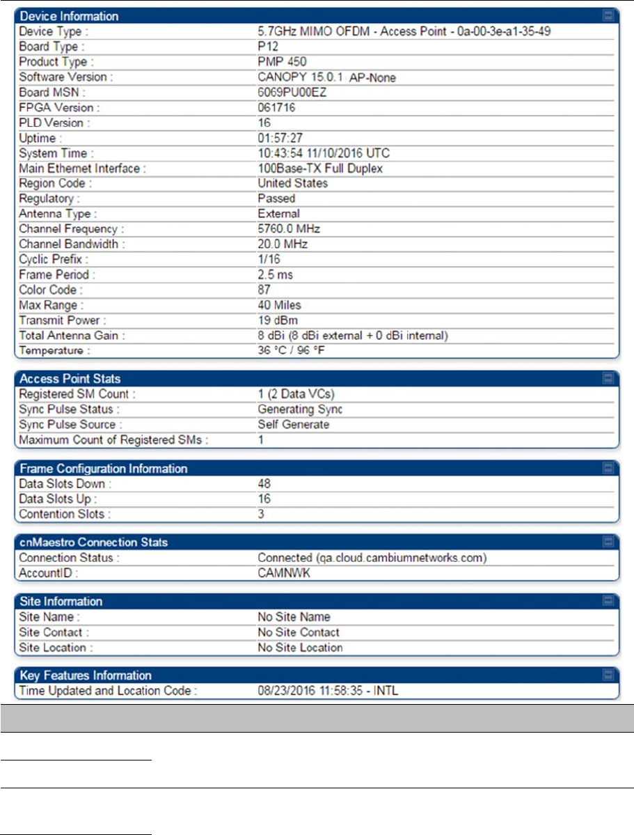
Chapter 9: Operation System information
Page 9-8
Table 208
General Status page attributes – PMP 450/450i AP
Attribute Meaning
Device Type See Table 207 General Status page attributes – PMP 450m AP on page 9-3
for details
Software Version
Board Type See Table 207 General Status page attributes – PMP 450m AP on page 9-3
for details

Chapter 9: Operation System information
Page 9-9
Product Type This indicates model of the device.
FPGA Version See Table 207 General Status page attributes – PMP 450m AP on page 9-3
for details
PLD Version
Uptime
System Time
Main Ethernet
Interface
Aux Ethernet Interface It is not supported for PMP 450 Series devices. See Table 207 General
Status page attributes – PMP 450m AP on page 9-3 for details
Region Code See Table 207 General Status page attributes – PMP 450m AP on page 9-3
for details
Regulatory
Antenna Type
Channel Center
Frequency
Channel Bandwidth
Cyclic Prefix
Frame Period
Color Code
Max Range
Transmitter Output
Power
This field indicates the combined power level at which the AP is set to
transmit, based on the Country Code and Antenna Gain settings.
Temperature See Table 207 General Status page attributes – PMP 450m AP on page 9-3
for details
802.3at Type 2 PoE
Status
The field displays whether PoE Classification functionality is enabled or
disabled. It is only applicable for 450i Series devices.
Registered SM Count See Table 207 General Status page attributes – PMP 450m AP on page 9-3
for details
Sync Pulse Status
Sync Pulse Source
Maximum Count of
Registered SMs
Data Slots Down
Data Slots Up

Chapter 9: Operation System information
Page 9-10
Contention Slots
Connection Status
Account ID See Table 207 General Status page attributes – PMP 450m AP on page 9-3
for details
Site Name
Site Contact
Site Location
Time Updated and
Location Code
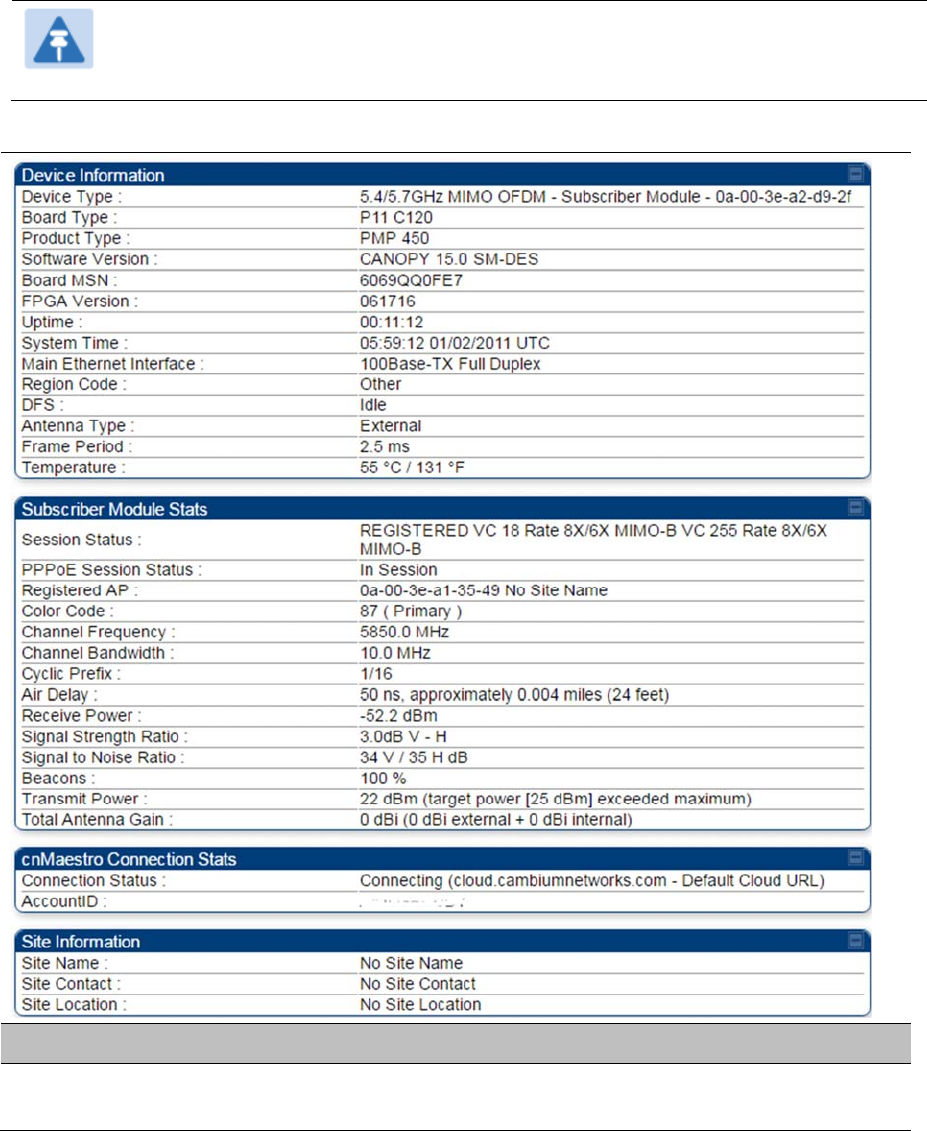
Chapter 9: Operation System information
Page 9-11
General Status page - SM
The SM’s
General Status
page is explained in Table 209.
Note
In order for accurate power level readings to be displayed, traffic must be present on the
radio link.
Table 209
General Status page attributes - SM
Attribute Meaning
Device Type This field indicates the type of the module. Values include the frequency band
of the SM, its module type and its MAC address.

Chapter 9: Operation System information
Page 9-12
Board Type This field indicates the series of hardware.
Product Type This indicates model of the device.
Software Version This field indicates the system release, the time and date of the release. If
you request technical support, provide the information from this field.
FPGA Version This field indicates the version of the field-programmable gate array (FPGA)
on the module. When you request technical support, provide the information
from this field.
PLD Version This field indicates the version of the programmable logic device (PLD) on the
module. If you request technical support, provide the value of this field.
Uptime This field indicates how long the module has operated since power was
applied.
System Time This field provides the current time. Any SM that registers to an AP inherits
the system time, which is displayed in this field as GMT (Greenwich Mean
Time).
Ethernet Interface This field indicates the speed and duplex state of Ethernet interface to the
SM.
Regional Code
A parameter that offers multiple fixed selections, each of which automatically
implements frequency band range restrictions for the selected region. Units
shipped to regions other than the United States must be configured with the
corresponding Country Code to comply with local regulatory requirements.
DFS This field indicates that DFS operation is enabled based on the configured
region code, if applicable.
Antenna Type The current antenna type that has been selected.
Frame Period This field indicates the current Frame Period setting of the radio in ms.
Temperature The current operating temperature of the board.
Session Status
This field displays the following information about the current session:
Scanning indicates that this SM currently cycles through the radio
frequencies that are selected in the Radio tab of the Configuration page.
Syncing indicates that this SM currently attempts to receive sync.
Registering indicates that this SM has sent a registration request message to
the AP and has not yet received a response.
Registered indicates that this SM is both:
registered to an AP.
ready to transmit and receive data packets.
Session Uptime This field displays the duration of the current link. The syntax of the displayed
time is hh:mm:ss.
Chapter 9: Operation System information
Page 9-13
Registered AP Displays the MAC address and site name of the AP to which the SM is
registered to. This parameter provides click-through proxy access to the AP’s
management interface.
Color Code This field displays a value from 0 to 254 indicating the SM’s configured color
code. For registration to occur, the color code of the SM and the AP must
match. Color code is not a security feature. Instead, color code is a
management feature, typically for assigning each sector a different color
code.
Color code allows you to force a SM to register to only a specific AP, even
where the SM can communicate with multiple APs. The default setting for the
color code value is 0. This value matches only the color code of 0 (not all 255
color codes).
Channel Frequency This field lists the current operating frequency of the radio.
Channel Bandwidth The size in MHz of the operating channel.
Cyclic Prefix OFDM technology uses a cyclic prefix, where a portion of the end of a symbol
(slot) is repeated at the beginning of the symbol to allow multi-pathing to
settle before receiving the desired data. A 1/16 cyclic prefix means that for
every 16 bits of throughput data transmitted, an additional bit is used.
Air Delay This field displays the distance in feet between this SM and the AP. To derive
the distance in meters, multiply the value of this parameter by 0.3048.
Distances reported as less than 200 feet (61 meters) are unreliable.
Receive Power This field lists the current combined receive power level, in dBm.
Signal Strength Ratio This field displays the difference of the Vertical path received signal power to
the Horizontal path received signal power.
Signal to Noise Ratio This field lists the current signal-to-noise level, an indication of the separation
of the received power level vs. noise floor.
Beacons Displays a count of beacons received by the SM in percentage. This value
must be typically between 99-100%. If lower than 99%, it indicates a
problematic link. This statistic is updated every 16 seconds.
Transmit Power This field lists the current combined transmit power level, in dBm.
Note
The red SM message “target power exceeded maximum”
does not necessarily indicate a problem.
In this case, the AP is requesting the SM to transmit at a
higher power level, but the SM is restricted due to EIRP limits
or hardware capabilities. This message can be an indication
that the SM is deployed further from the AP than optimal,
causing the AP to adjust the SM to maximum transmit power.
Chapter 9: Operation System information
Page 9-14
Data Slots Down This field lists the number of slots used for downlink data transmission.
Data Slots Up This field lists the number of slots used for uplink data transmission.
Contention Slots This field indicates the number of (reserved) Contention Slots configured by
the operator. See Contention slots on page7-176.
Site Name This field indicates the name of the physical module. You can assign or
change this name in the SNMP tab of the SM Configuration page. This
information is also set into the
sysName
SNMP MIB-II object and can be
polled by an SNMP management server.
Site Contact This field indicates contact information for the physical module. You can
provide or change this information in the SNMP tab of the SM Configuration
page. This information is also set into the
sysName
SNMP MIB-II object and
can be polled by an SNMP management server.
Site Location This field indicates site information for the physical module. You can provide
or change this information in the SNMP tab of the SM Configuration page.
Maximum Throughput This field indicates the limit of aggregate throughput for the SM and is based
on the default (factory) limit of the SM and any floating license that is currently
assigned to it.
Time Updated and
Location Code
This field displays information about the keying of the radio.
Note
For PMP 450 SM 900 MHz, there is additional parameter Path Info (under Subscriber
Module Stats) which displays polarization path(A & B) information.
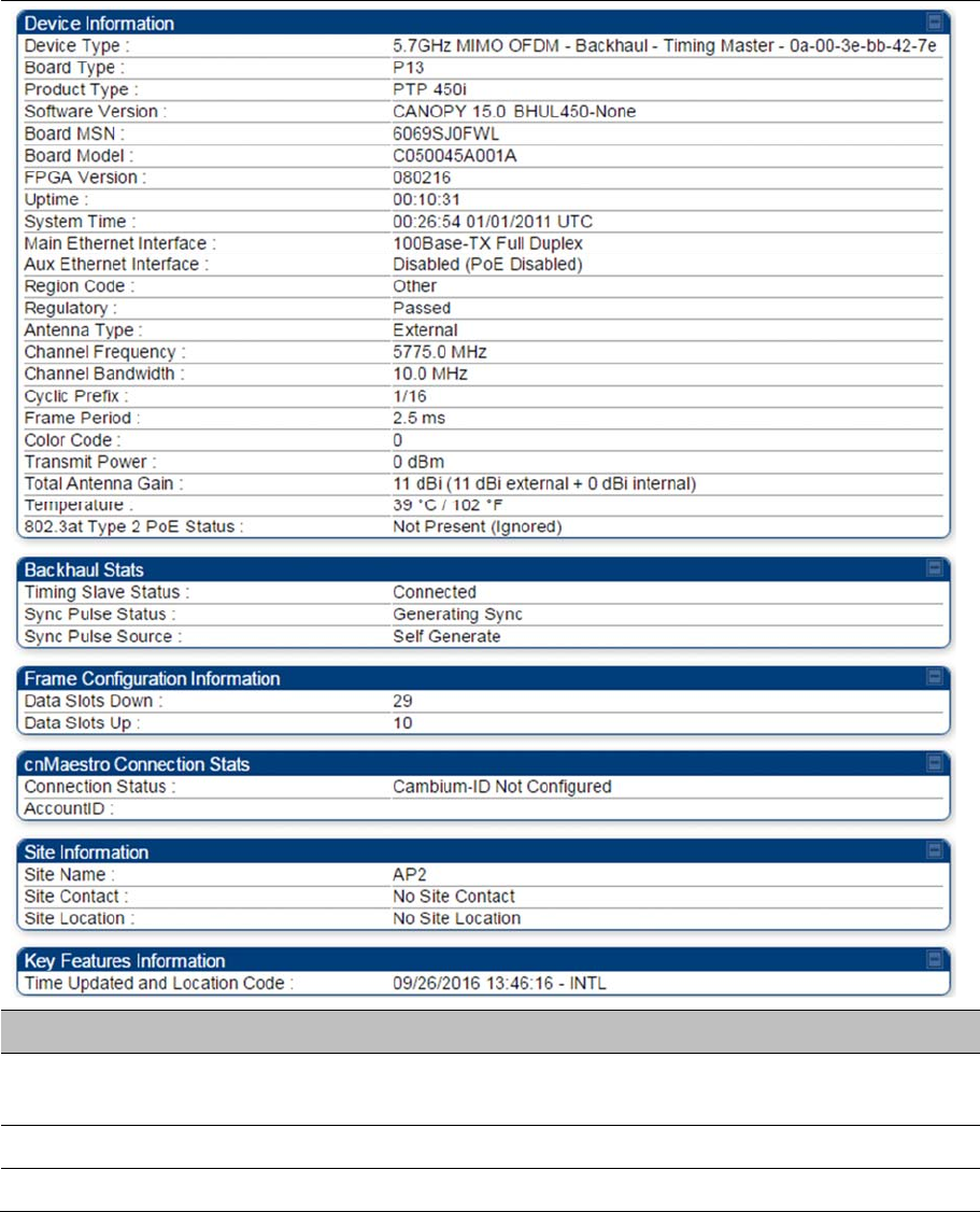
Chapter 9: Operation System information
Page 9-15
General Status page of BHM
The BHM’s
General Status
page is explained in Table 210.
Table 210
General Status page attributes - BHM
Attribute Meaning
Device Type This field indicates the type of the module. Values include the frequency band
of the BHM, its module type and its MAC address.
Board Type This field indicates the series of hardware.
Product Type This indicates model of the device.

Chapter 9: Operation System information
Page 9-16
Software Version This field indicates the system release, the time and date of the release. If
you request technical support, provide the information from this field.
Board MSN This field indicates the Manufacture’s Serial number. A unique serial number
assigned to each radio at the factory for inventory and quality control.
FPGA Version This field indicates the version of the field-programmable gate array (FPGA)
on the module. When you request technical support, provide the information
from this field.
Uptime This field indicates how long the module has operated since power was
applied.
System Time This field provides the current time. Any BHS that registers to a BHM inherits
the system time, which is displayed in this field as GMT (Greenwich Mean
Time).
Ethernet Interface This field indicates the speed and duplex state of Ethernet interface to the
BHM.
Antenna Type The current antenna type that has been selected.
Temperature The current operating temperature of the board.
Session Status
This field displays the following information about the current session:
Scanning indicates that this BHS currently cycles through the radio
frequencies that are selected in the Radio tab of the Configuration page.
Syncing indicates that this BHM currently attempts to receive sync.
Registering indicates that this BHM has sent a registration request message
to the BHM and has not yet received a response.
Registered indicates that this BHM is both:
Registered to a BHM.
Ready to transmit and receive data packets.
Session Uptime This field displays the duration of the current link. The syntax of the displayed
time is hh:mm:ss.
Registered Backhaul Displays the MAC address and site name of the BHM to which the BHS is
registered to. This parameter provides click-through proxy access to the
BHM’s management interface.
Channel Frequency This field lists the current operating frequency of the radio.
Receive Power This field lists the current combined receive power level, in dBm.
Signal Strength Ratio This field displays the difference of the Vertical path received signal power to
the Horizontal path received signal power.
Transmit Power This field lists the current combined transmit power level, in dBm.
Signal to Noise Ratio This field lists the current signal-to-noise level, an indication of the separation
of the received power level vs. noise floor.

Chapter 9: Operation System information
Page 9-17
Beacons Displays a count of beacons received by the BHM in percentage. This value
must be typically between 99-100%. If lower than 99%, it indicates a
problematic link. This statistic is updated every 16 seconds.
Air Delay This field displays the distance in feet between this BHS and the BHM. To
derive the distance in meters, multiply the value of this parameter by 0.3048.
Distances reported as less than 200 feet (61 meters) are unreliable.
Data Slots Down This field lists the number of slots used for downlink data transmission.
Data Slots Up This field lists the number of slots used for uplink data transmission.
Regional Code
A parameter that offers multiple fixed selections, each of which automatically
implements frequency band range restrictions for the selected region. Units
shipped to regions other than the United States must be configured with the
corresponding Country Code to comply with local regulatory requirements.
Site Name This field indicates the name of the physical module. Assign or change this
name in the Configuration > SNMP page. This information is also set into
the sysName SNMP MIB-II object and can be polled by an SNMP
management server.
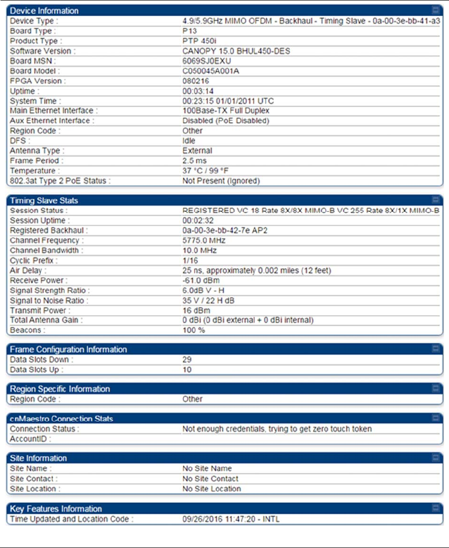
Chapter 9: Operation System information
Page 9-18
General Status page of BHS
The BHS’s
General Status
page is explained in Table 211.
Table 211
General Status page attributes - BHS

Chapter 9: Operation System information
Page 9-19
Attribute Meaning
Device Type
See Table 211 on page 9-18
Board Type
Software Version
Board MSN
FPGA Version
Uptime
See Table 211 on page 9-18
System Time
Ethernet Interface
Antenna Type
Temperature
Session Status
Session Uptime
Registered Backhaul
Channel Frequency
Receive Power
Signal Strength Ratio
Transmit Power
Signal to Noise Ratio
Beacons
Air Delay
Data Slots Down
Data Slots Up
Regional Code
Site Name
Site Contact
Site Location
Time Updated and
Location Code
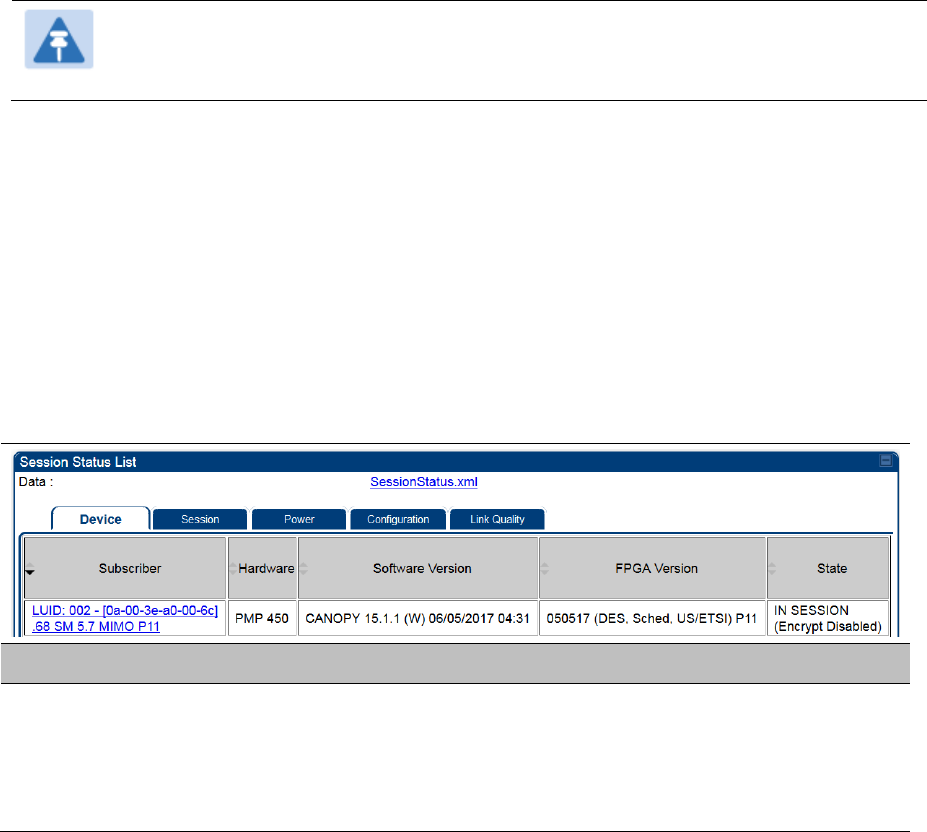
Chapter 9: Operation System information
Page 9-20
Viewing Session Status
The Session Status page in the Home page provides information about each SM or BHS that has
registered to the AP or BHM. This information is useful for managing and troubleshooting a system. This
page also includes the current active values on each SM or BHS for MIR and VLAN, as well as the
source of these values, representing the SM/BHS itself, Authentication Server, or the Authentication
Server and SM/BHS.
Note
In order for accurate power level readings to be displayed, traffic must be present on the
radio link.
The Session Status List has four tab: Device, Session, Power and Configuration.
The SessionStatus.xml hyper link allows user to export session status page from web management
interface of AP or BHM. The session status page will be exported in xml file.
Device tab
The Device tab provides information on the Subscriber’s LUID and MAC, Hardware, Software, FPGA
versions and the state of the SM/BHS (Registered and/or encrypted).
Table 212 Device tab attributes
Attribute Meaning
Subscriber This field displays the LUID (logical unit ID), MAC address and Site Name of
the SM/BHS. As each SM or BHS registers to the AP/BHM, the system
assigns an LUID of 2 or a higher unique number to the SM/BHS. If a SM/BHS
loses registration with the AP/BHS and then regains registration, the SM/BHS
will retain the same LUID.
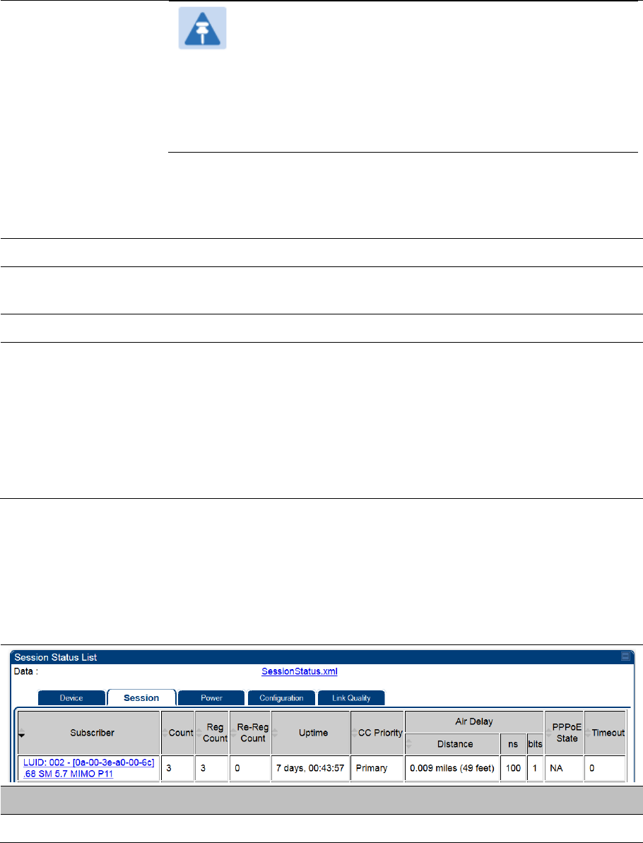
Chapter 9: Operation System information
Page 9-21
Note
The LUID associated is lost when a power cycle of the
AP/BHM occurs.
Both the LUID and the MAC are hot links to open the interface
to the SM/BHS. In some instances, depending on network
activity and network design, this route to the interface yields a
blank web page. If this occurs, refresh your browser view.
Site Name indicates the name of the SM/BHS. Change this name on the
Configuration web page of the SM/BHS. This information is also set into the
sysName SNMP MIB-II object and can be polled by an SNMP management
server.
Hardware This field displays the SMs or BHS hardware type.
Software Version This field displays the software release that operates on the SM/BHS, the
release date and time of the software.
FPGA Version This field displays the version of FPGA that runs on the SM/BHS
State
This field displays the current status of the SM/BHS as either
IN SESSION to indicate that the SM/BHS is currently registered to the
AP/BHM.
IDLE to indicate that the SM/BHS was registered to the AP/BHM at one
time, but now is not.
This field also indicates whether the encryption scheme in the module is
enabled.
Session tab
The Session tab provides information on the SMs or BHS Session Count, Reg Count, Re-Reg Count,
Uptime, Air delay, PPPoE State and Timeouts.
Table 213 Session tab attributes
Attribute Meaning
Subscriber See Table 212 on page 9-20.
Chapter 9: Operation System information
Page 9-22
Count This field displays how many sessions the SM/BHS has had with the
AP/BHM. Typically, this is the sum of Reg Count and Re-Reg Count.
However, the result of internal calculation may display here as a value that
slightly differs from the sum.
If the number of sessions is significantly greater than the number for other
SMs or BHS, then this may indicate a link problem or an interference
problem.
Reg Count When a SM/BHS makes a Registration Request, the AP/BHM checks its local
session database to see whether it was registered earlier. If the AP/BHM
concludes that the SM/BHS is not currently in session database and it is valid
Registration Request, then the request increments the value of this field.
In ideal situation, the Reg Count indicates total number of connected SMs to
an AP.
Note
The user can clear Reg Count by dropping all current sessions
of SM (or BHS) from Configuration > Tools > Sessions menu.
Re-Reg Count
When a SM/BHS makes a Registration Request, the AP/BHM checks its local
session database to see whether it was registered earlier. If the AP/BHM
concludes that the SM/BHS is currently in session database, then the request
increments the value of this field.
Typically, a Re-Reg is the case where both:
SM/BHS attempts to reregister for having lost communication with the
AP/BHM.
AP/BHM has not yet observed the link to the SM/BHS as being down.
It is possible for a small period of time if there is no downlink traffic and
AP/BHM still assumes the session is up, but the SM/BHS, loses session and
quickly re-connects before the AP/BHM knew the session had dropped. This
is how a re-registration happens.
If the number of sessions is significantly greater than the number for other
SMs or BHS, then this may indicate a link problem (check mounting,
alignment, receive power levels) or an interference problem (conduct a
spectrum scan).
Uptime Once a SM/BHS successfully registers to an AP/BHM, this timer is started. If
a session drops or is interrupted, this timer is reactivated once re-registration
is complete.
CC Priority The field displays Color Code Priority (ICC, Primary, Secondary or Tertiary) of
all connected SM.
AirDelay This field displays the distance of the SM/BHS from the AP/BHM in meters,
nanoseconds and bits. At close distances, the value in this field is unreliable.
Chapter 9: Operation System information
Page 9-23
PPPoE state This field displays the current PPPoE state (whether configured) of the
SM/BHS.
Timeout This field displays the timeout in seconds for management sessions via
HTTP, ftp access to the SM/BHS. 0 indicates that no limit is imposed.
Power tab
Table 214 Power tab attributes
Attribute Meaning
Subscriber See Table 212 on page 9-20.
Hardware This field displays the SMs or BHS hardware type.
Downlink Rate SU-
MIMO
This field displays whether the high-priority channel is enabled in the SM/BHS
and the status of rate adapt. For example, if “8X/4X” is listed, the radio is
capable of operating at 8X but is currently operating at 4X, due to RF
conditions.
This field also states whether it is MIMO-A or MIMO-B radio e.g. “8X/8X
MIMO-B” indicates MIMO-B and “8X/4X MIMO-A” indicates MIMO-A.
A VC starts at its lowest modulation and slowly rate adapts up, as traffic is
successfully transmitted over the VC. It is normal for one VC to have a
different modulation rate than another VC, if only one VC has traffic on it. For
example if High Priority VC is enabled, but only low priority VC has traffic the
reading will show:
REGISTERED VC 18 Rate 8X/8X MIMO-B VC 255 Rate 8X/1X MIMO-B
Note: The SU-MIMO rate applies to all AP platforms. For 450m, this field
indicates the rate being used for symbols where this particular VC is not being
MU-MIMO grouped with other SM’s.
Downlink Rate MU-
MIMO
The MU-MIMO rate applies only to the 450m AP. This rate indicates the
modulation used for symbols where this particular low priority VC is MU-
MIMO scheduled, by grouping it in the same slot with other low priority VC’s
AP Rx Power (dBm) This field indicates the AP’s or BHM’s combined receive power level for the
listed SM/BHS.

Chapter 9: Operation System information
Page 9-24
Signal Strength Ratio
(dB)
This field displays the ratio of the Vertical path received signal power to the
Horizontal path received signal power. This ratio can be useful for
determining multipathing conditions (high vertical to horizontal ratio) for
Uplink.
Signal to Noise Ratio
(dB)
This field lists the current signal-to-noise level, an indication of the separation
of the received power level vs. noise floor. In other words, it indicates signal
to noise ratio for Uplink.
Chapter 9: Operation System information
Page 9-25
Configuration tab
The Configuration tab provides information on the SMs or BHS Uplink or Downlink (UL/DL) Sustained
Data Rate, UL/DL Burst Allocation, UL/DL Burst Rate, UL/DL Low Priority CIR, UL/DL High CIR, UL/DL
High Priority Queue Information and the UL/DL Broadcast or Multicast Allocation. This data is refreshed
based on the Web Page Auto Update setting on the AP’s or BHS’s General Configuration page.
Table 215 Configuration tab attributes
Attribute Meaning
Subscriber See Table 212 on page 9-20.
Sustained Data Rate
Cap (kbps)
This field specifies the maximum sustained data rate between SM/BHS and
AP/BHM. If this field displays “Uncapped”, then there is no limit set for data
rate. If this field displays 4000, then the maximum sustained data rate
between SM/BHS and AP/BHM is limited to 4000 kbps.
Sustained Data Rate
(kbps) - Uplink
This field displays the value that is currently in effect for the SM/BHS, with the
source of that value in parentheses. This is the specified rate at which each
SM/BHS registered to this AP/BHM is replenished with credits for
transmission. The configuration source of the value is indicated in
parentheses.
See Maximum Information Rate (MIR) Parameters on page 7-198.
Sustained Data Rate
(kbps) - Downlink
This field displays the value that is currently in effect for the SM/BHS, with the
source of that value in parentheses. This is the specified the rate at which the
AP/BHM should be replenished with credits (tokens) for transmission to each
of the SMs/BHS’s in its sector. The configuration source of the value is
indicated in parentheses.
See Maximum Information Rate (MIR) Parameters on page 7-198.

Chapter 9: Operation System information
Page 9-26
Burst Allocation (kbit) -
Uplink
This field displays the value that is currently in effect for the SM/BHS, with the
source of that value in parentheses. This is the specified maximum amount of
data that each SM/BHS is allowed to transmit before being recharged at the
Sustained Uplink Data Rate with credits to transmit more. The configuration
source of the value is indicated in parentheses.
See Interaction of Burst Allocation and Sustained Data Rate Settings on page
7-200
Burst Allocation (kbit) -
Downlink
This field displays the value that is currently in effect for the SM/BHS, with the
source of that value in parentheses. This is the specified the rate at which the
AP/BHM should be replenished with credits (tokens) for transmission to each
of the SMs/BHS’s in its sector. The configuration source of the value is
indicated in parentheses.
See Interaction of Burst Allocation and Sustained Data Rate Settings on page
7-200
Max Burst Rate (kbit) -
Uplink
The data rate at which an SM/BHS is allowed to burst (until burst allocation
limit is reached) before being recharged at the Sustained Uplink Data Rate
with credits to transit more. When set to 0 (default), the burst rate is unlimited.
See Interaction of Burst Allocation and Sustained Data Rate Settings on page
7-200
Max Burst Rate (kbit) -
Downlink
The data rate at which an SM/BHS is allowed to burst (until burst allocation
limit is reached) before being recharged at the Sustained Downlink Data
Rate with credits to transit more. When set to 0 (default), the burst rate is
unlimited.
See Interaction of Burst Allocation and Sustained Data Rate Settings on page
7-200
Low Priority CIR This field indicates the minimum rate at which low priority traffic is sent over
the uplink and downlink (unless CIR is oversubscribed or RF link quality is
degraded).
High CIR This field indicates the minimum rate at which high priority traffic is sent over
the uplink and downlink (unless CIR is oversubscribed or RF link quality is
degraded).
Broadcast/Multicast
Allocation
This field displays the data rate at which Broadcast and Multicast traffic is
sent via the radio link.
RADIUS
Authentication Reply
This field displays whether RADIUS server is reachable or not.
RADIUS
Authentication Server
This field displays the associated RADIUS Authentication Server for each SM
where it was authenticated. This information is useful when there are multiple
RADIUS servers (maximum three servers supported by Cambium). If one
server is not reachable, other configured servers are tried in sequential order
as a fall-back. In this scenario, the Session Status is useful to identify
associate RADIUS Authentication Server for all connected SMs.

Chapter 9: Operation System information
Page 9-27
Table 216 Session Status > Configuration CIR configuration denotations
Attribute Meaning
(SM) QoS/VLAN parameters are derived from the SM’s/BHS’s settings
(APCAP) QoS/VLAN parameters are derived from the AP’s settings, including any
keyed capping (for radios capped at 4 Mbps, 10 Mbps, or 20 Mbps)
(D) QoS/VLAN parameters are retrieved from the device, due to failed retrieval
from the AAA or WM server.
(AAA) QoS/VLAN parameters are retrieved from the RADIUS server
(BAM) QoS/VLAN parameters are retrieved from a WM BAM server