Cambium Networks 50450M 5GHz Point to MultiPoint Multi User MIMO Access Point User Manual USERS MANUAL PART4
Cambium Networks Limited 5GHz Point to MultiPoint Multi User MIMO Access Point USERS MANUAL PART4
Contents
- 1. USER GUIDE P1
- 2. USER GUIDE P2
- 3. USER GUIDE P3
- 4. USER GUIDE P4
- 5. User manual
- 6. User Manual
- 7. USERS MANUAL PART1
- 8. USERS MANUAL PART2
- 9. USERS MANUAL PART3
- 10. USERS MANUAL PART4
- 11. USER MANUAL PART1
- 12. USER MANUAL PART2
- 13. USER MANUAL PART 3
- 14. USER MANUAL PART 4
- 15. USER MANUAL PT1
- 16. USER MANUAL PT2
- 17. USER MANUAL PT3
USERS MANUAL PART4
Chapter 9: Operation System information
Page 9-28
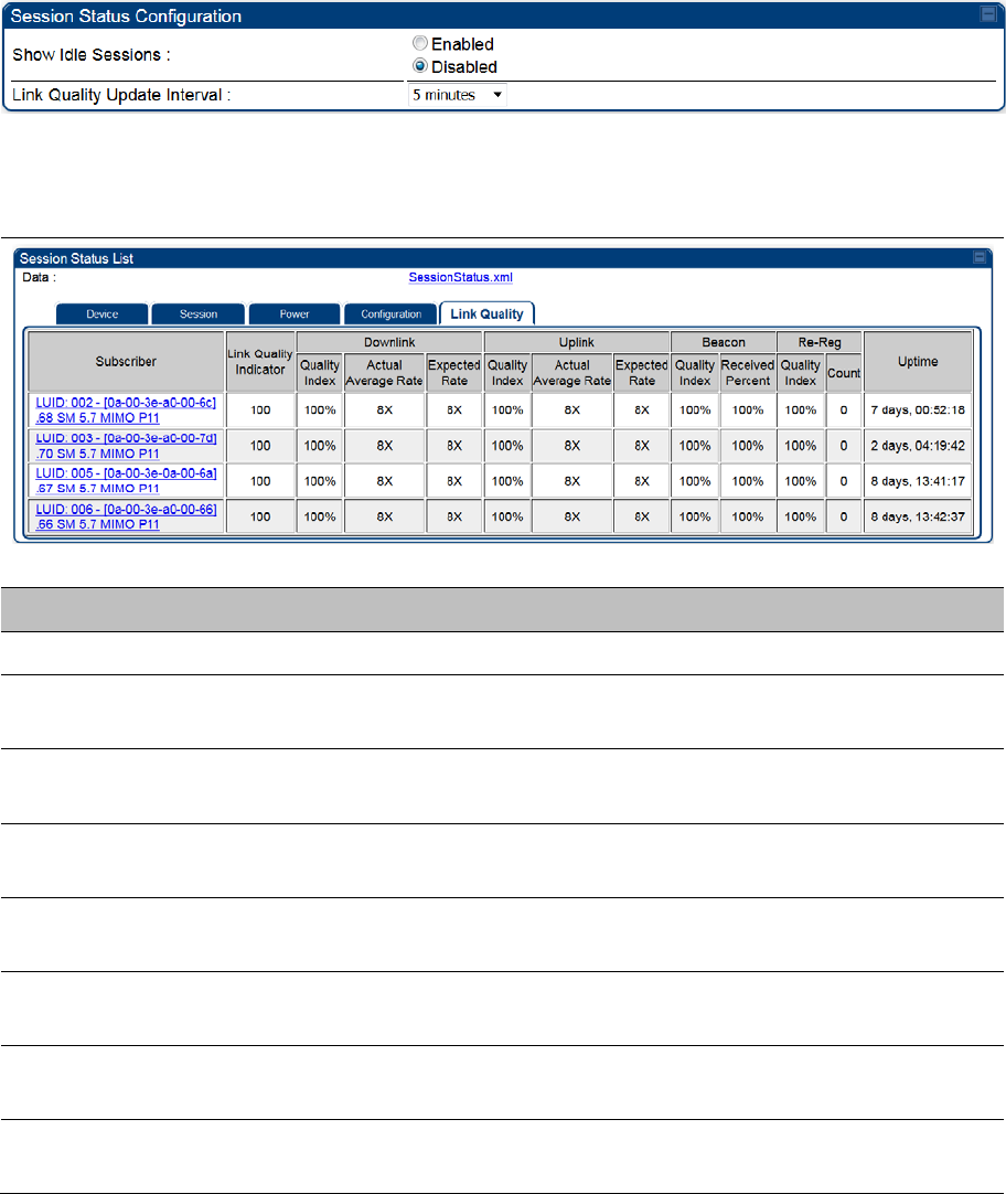
Link Quality tab
The Link Quality tab provides information on the Subscriber’s UID, Link quality, Downlink, Uplink,
Beacon, ReReg, and the Uptime.
This data is refreshed based on the Link Quality Update Interval parameter configuration under the
Sessions Status page.
The Link Quality tab displays the calculated Link Quality Indicator (LQI) for the configured interval (Link
Quality Update Interval parameter).
Table 217 Link Quality tab attributes
Attribute Meaning
Subscriber See Table 212 on page 9-20.
Link Quality Indicator This field displays quality of the link. It is calculated based on receive power,
modulation rate, re-registrations and beacon percentage.
Downlink - Quality
Index
This field displays the downlink quality in percentage. It is calculated based
on Downlink receiver power, modulation rate, and beacon percentage.
Downlink -Actual
Average Rate
This field displays the average Downlink modulation rate. For 450m, this field
specifies the SU-MIMO Modulation Rate.
Downlink - Expected
Rate
This field displays the expected modulation rate based on receive power in
Downlink.
Uplink - Quality Index This field displays the uplink quality in percentage. It is calculated based on
Uplink receiver power and modulation rate.
Uplink -Actual
Average Rate
This field displays the average Uplink modulation rate.
Uplink - Expected
Rate
This field displays the expected modulation rate based on receive power in
Uplink.
Chapter 9: Operation System information
Page 9-29
Beacon - Quality
Index
This field displays the beacon quality index. It is calculated based on beacon
percentage.
Beacon - Received
Percent
This field displays the received beacon percentage.
Re-Reg - Quality
Index
This field displays the re-registration quality. It is calculated based on the re-
registration count.
Re-Reg Count This field displays the number of re-registrations.
Uptime This field displays the uptime of the device.
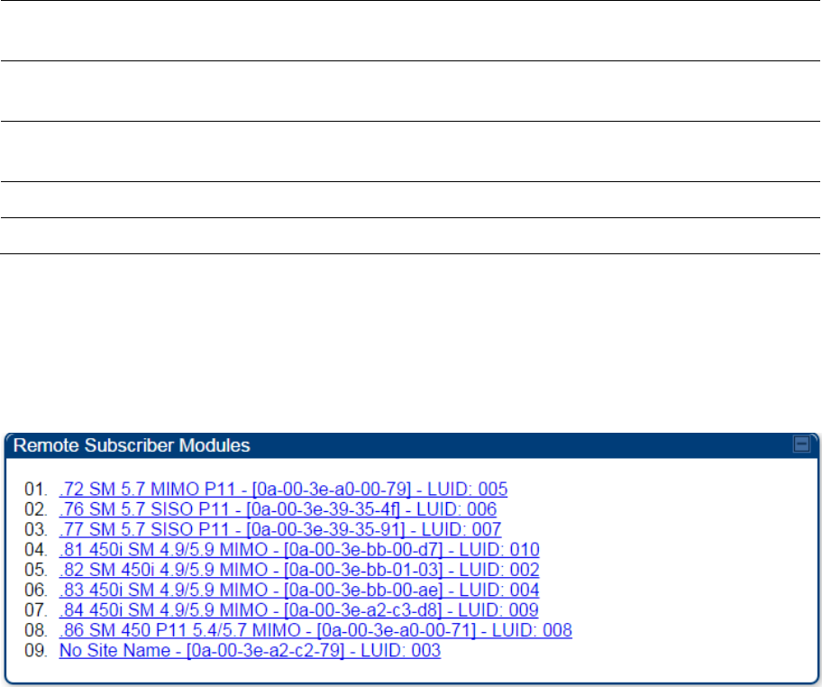
Viewing Remote Subscribers
This page allows to view the web pages of registered SMs or BHS over the RF link. To view the pages for
a selected SM/BHS, click its link. The General Status page of the SM opens.
Figure 193 Remote Subscribers page of AP
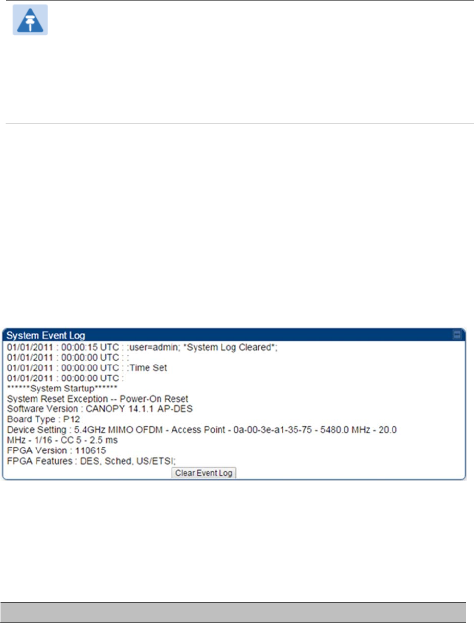
Interpreting messages in the Event Log
Each line in the Event Log of a module Home page begins with a time and date stamp. However, some of
these lines wrap as a combined result of window width, browser preferences and line length. You may
find this tab easiest to use if you expand the window till all lines are shown beginning with time and date
stamp.
Time and Date Stamp
The time and date stamp reflect one of the following:
GPS time and date directly or indirectly received from the CMM4.
NTP time and date from a NTP server (CMM4 may serve as an NTP server)
The running time and date that you have set in the Time & Date web page.
Chapter 9: Operation System information
Page 9-30
Note
In the Time & Date web page, if you have left any time field or date field unset and clicked
the
Set Time and Date
button, then the time and date default to
00:00:00 UT :
01/01/00
.
A reboot causes the preset time to pause or, in some cases, to run in reverse. Additionally, a
power cycle resets the running time and date to the default
00:00:00 UT : 01/01/00
.
Thus, whenever either a reboot or a power cycle has occurred, must reset the time and date
in the Time & Date web page of any module that is not set to receive sync.
Event Log Data Collection
The collection of event data continues through reboots and power cycles. When the buffer allowance for
event log data is reached, the system adds new data into the log and discards an identical amount of the
oldest data.
Each line that contains the expression WatchDog flags an event that was both:
considered by the system software to have been an exception
recorded in the preceding line.
Conversely, a Fatal Error () message flags an event that is recorded in the next line. Some exceptions
and fatal errors may be significant and require either operator action or technical support.
Figure 194
Event log data
Messages that Flag Abnormal Events
The messages listed below flag abnormal events and, case by case, may signal the need for corrective
action or technical support.
Table 218
Event Log messages for abnormal events
Event Message Meaning

Chapter 9: Operation System information
Page 9-31
Expected LUID = 6
Actual LUID = 7
Something is interfering with the control messaging of the module. Also
ensure that you are using shielded cables to minimize interference. Consider
trying different frequency options to eliminate or reduce interference.
FatalError() The event recorded on the line immediately beneath this message triggered
the Fatal Error ().
Loss of GPS Sync
Pulse Module has lost GPS sync signal.
Machine Check
Exception
This is a symptom of a possible hardware failure. If this is a recurring
message, begin the RMA process for the module.
RcvFrmNum =
0x00066d
ExpFrmNum =
0x000799
Something is interfering with the control messaging of the module. Also
ensure that you are using shielded cables to minimize interference. Consider
trying different frequency options to eliminate or reduce interference.
System Reset
Exception -- External
Hard Reset
The unit lost power or was power cycled.
System Reset
Exception -- External
Hard Reset WatchDog
The event recorded on the preceding line triggered this WatchDog message.
Messages that Flag Normal Events
The messages listed below record normal events and typically do not signal a need for any corrective
action or technical support.
Table 219 Event Log messages for normal events
Event Message Meaning
Acquired GPS Sync
Pulse. Module has acquired GPS sync signal.
FPGA Features Type of encryption.
FPGA Version FPGA (JBC) version in the module.
GPS Date/Time Set Module is now on GPS time.
Reboot from Webpage Module was rebooted from management interface.
Software Boot Version Boot version in the module.
Software Version The software release and authentication method for the unit.
System Log Cleared Event log was manually cleared.
Chapter 9: Operation System information
Page 9-32
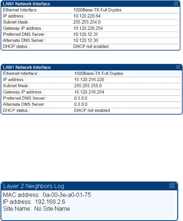
Viewing the Network Interface
In any module, the LAN1 Network Interface section of this tab displays the defined Internet Protocol
scheme for the Ethernet interface to the module. In SM/BHS devices, this page also provides an RF
Public Network Interface section, which displays the Internet Protocol scheme defined for network access
through the master device (AP/BHM).
Figure 195
Network Interface tab of the AP
Figure 196
Network Interface tab of the SM
Viewing the Layer 2 Neighbors
In the Layer 2 Neighbors tab, a module reports any device from which it has received a message in Link
Layer Discovery Protocol within the previous two minutes. Given the frequency of LLDP messaging, this
means that the connected device will appear in this tab 30 seconds after it is booted and remain until two
minutes after its shutdown.
Figure 197
Layer 2 Neighbors page
Chapter 9: Operation System statistics
Page 9-33
System statistics
This section describes how to use the system statistics pages to manage the performance of the
PMP/PTP 450 Platform Family link.
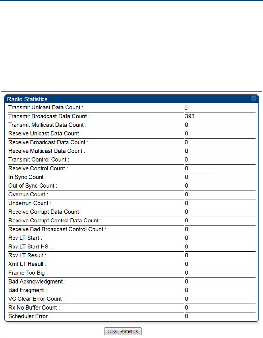
Viewing the Scheduler statistics
The Statistics > Scheduler page is applicable for all modules (AP/SM/BHM/BHS) and the parameters
are displayed as shown below:
Table 220 Scheduler tab attributes

Chapter 9: Operation System statistics
Page 9-34
Attribute Meaning
Transmit Unicast Data
Count Total amount of unicast packets transmitted from the radio
Transmit Broadcast
Data Count Total amount of broadcast packets transmitted from the radio
Transmit Multicast
Data Count Total amount of multicast packets transmitted by the radio
Receive Unicast Data
Count Total amount of unicast packets received by the radio
Receive Broadcast
Data Count Total amount of broadcast packets received by the radio
Receive Multicast
Data Count Total amount of multicast packets received by the radio
Transmit Control
Count
Amount of radio control type messages transmitted (registration requests and
grants, etc.)
Receive Control Count Amount of radio control type messages received (registration requests and
grants, etc.)
In Sync Count Number of times the radio has acquired sync. When GPS synchronization is
used it is number of times GPS sync acquired. For the SM, itis the number of
times the SM successfully obtained sync with an AP.
Out of Sync Count Number of times the radio lost same sync lock
Overrun Count Number of times FPGA frame has overrun its TX Frame
Underrun Count Number of times FPGAs TX Frame aborted prematurely
Receive Corrupt Data
Count Number of times a corrupt packet has been received at the FPGA.
Receive Corrupt
Control Data Count
Number of times a corrupt control data packet has been received at the
FPGA.
Receive Bad
Broadcast Control
Count
Number of times the radio has received an invalid control message via
broadcast (SM only).
Rcv LT Start Number of Link Test Start messages received. A remote radio has requested
that this radio start a link test to it.
Rcv LT Start HS Number of Link Test Start Handshake messages received. This radio
requested that a remote radio start a link test and the remote radio has sent a
handshake back acknowledging the start.
Chapter 9: Operation System statistics
Page 9-35
Rcv LT Result This radio received Link Test results from the remote radio under test. When
this radio initiates a link test, the remote radio will send its results to this radio
for display.
Xmt LT Result This radio transmitted its link test results to the remote radio under test. When
the remote radio initiates a link test, this radio must send its results to the
remote radio for display there.
Frame Too Big This statistics indicates the number of packets received and processed by the
radios which were greater than max packet size 1700 bytes.
Bad Acknowledgment This statistics indicates the number of packets received as bad
acknowledgment. It is for engineering use only.
Bad Fragment This statistic indicates number of fragments tagged internally as bad. It is for
engineering use only.
VC Clear Error Count This statistic indicates number of times VC clear failed.
Rx No Buffer Count Currently unused
Scheduler Error This error is incremented when the scheduler cannot send or get scheduled
to send a packet. t is also general called a “VC Error”.
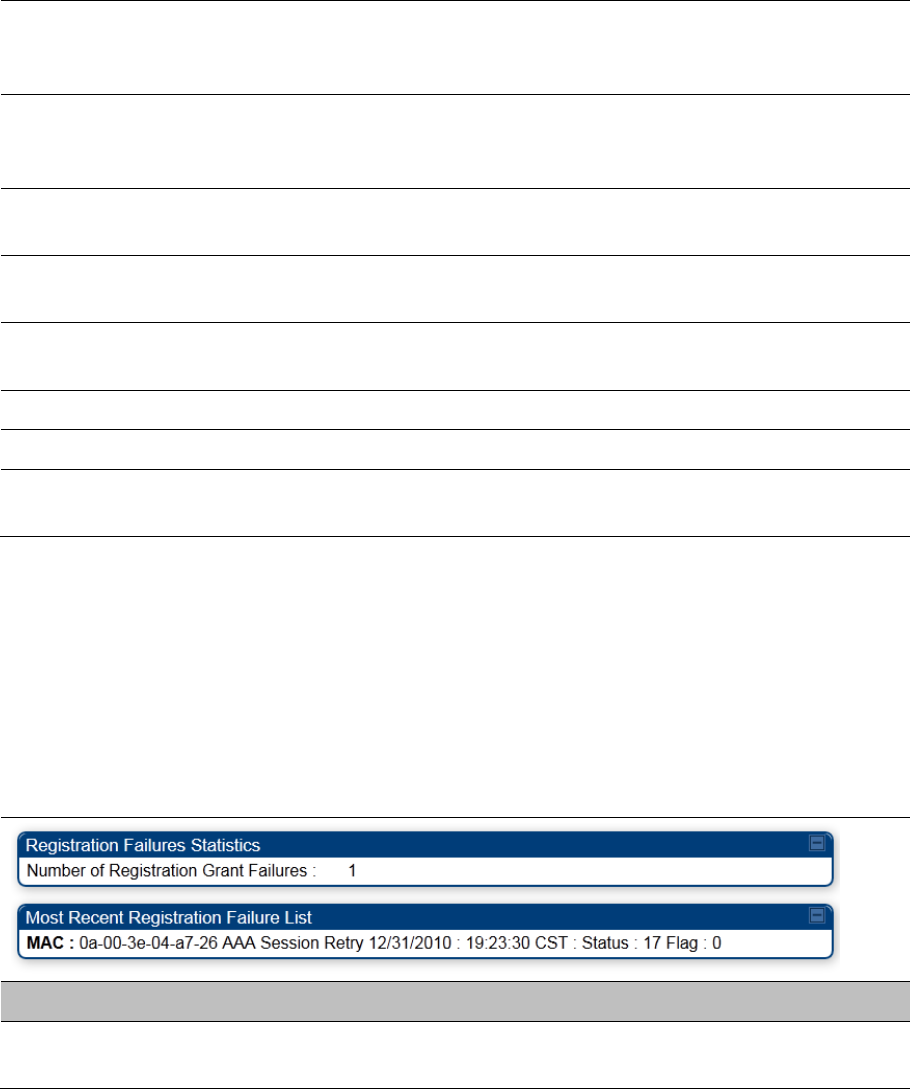
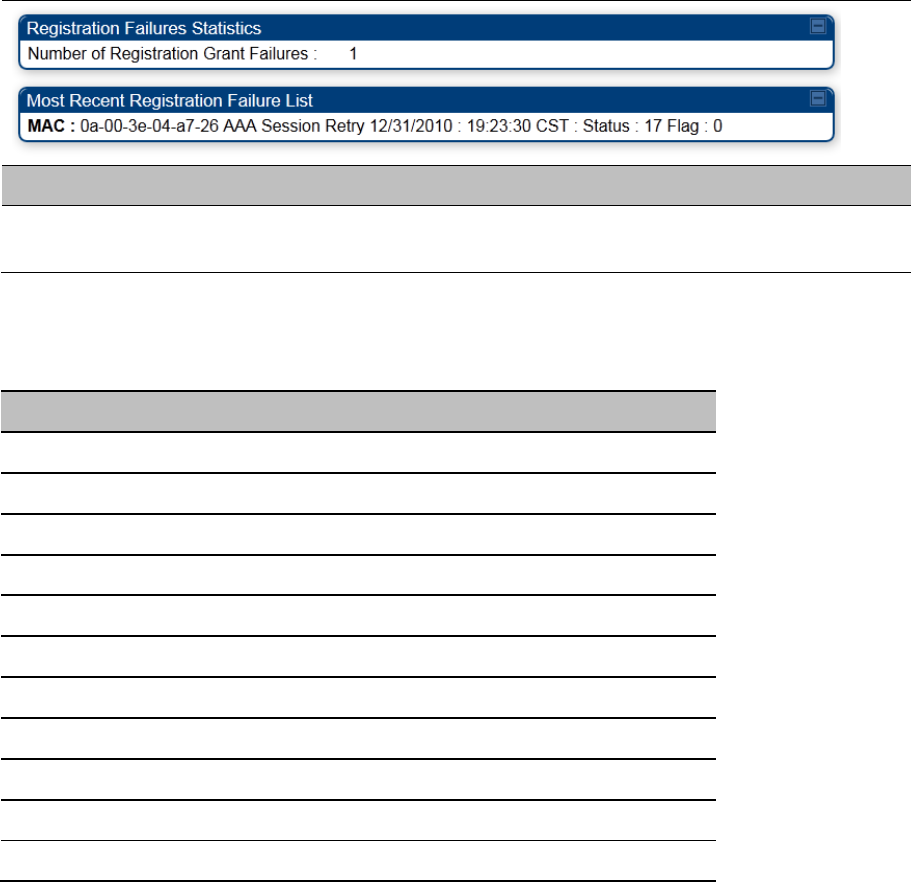
Viewing list of Registration Failures statistics
SM Registration Failures page of AP
The SM Registration Failures tab identifies SMs that have recently attempted and failed to register to this
AP. With its time stamps, these instances may suggest that a new or transient source of interference
exists.
Table 221 SM Registration Failures page attributes - AP
Attribute Meaning
Status 17 Flag 0 No response was received from the AAA server and hence SM is trying to
send a session request again.
Chapter 9: Operation System statistics
Page 9-36
BHS Registration Failures page of BHM
Table 222 BHS Registration Failures page attributes - BHM
Attribute Meaning
Status 17 Flag 0 No response was received from the AAA server and hence SM is trying to
send a session request again.
There is a list of flags from 0 to 20 as shown in Table 223 and the “Flags” can be ignored.
Table 223 Flags status
Flag Meaning Flag Meaning
0 Normal 11 AP Lite Limit Reached
1 Out of Range 12 Only Ver 9.5+ Allowed
2 No Luids 13 Temporary Data VC for AAA
3 BH ReRange 14 AAA Authentication Failure
4 Auth Fail 15 Registration Grant Reject
5 Encrypt Fail 16 Blank
6 Power Adjust 17 AAA Session Retry
7 No VCs 18 AAA Reauth Failure
8 Reserve VC Fail 19 RegReq at zero power
9 Activate VC Fail 20 RegReq no time ref
10 Hi VC Setup Fail - -
Chapter 9: Operation System statistics
Page 9-37
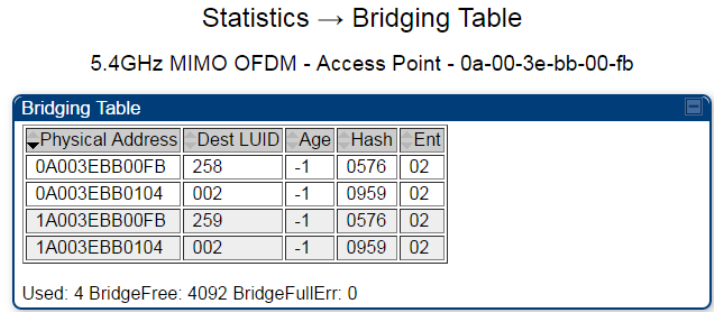
Interpreting Bridging Table statistics
If NAT (network address translation) is not active on the SM/BHS, then the Bridging Table page provides
the MAC address of all devices that are attached to registered SMs/BHS (identified by LUIDs).
The SM/BHS management MAC addresses are also added in bridge table upon SMs/BHS registration.
These entries will be remove automically from the table once SMs/BHS is de-registered. This alleviates
the arp cache > bridge cache timeout problems.
The bridging table allows data to be sent to the correct module as follows:
For the AP/BHM, the uplink is from RF to Ethernet. Thus, when a packet arrives in the RF interface to
the AP/BHM, the AP/BHM reads the MAC address from the inbound packet and creates a bridging
table entry of the source MAC address on the other end of the RF interface.
For the SM/BHS, the uplink is from Ethernet to RF. Thus, when a packet arrives in the Ethernet
interface to one of these modules, the module reads the MAC address from the inbound packet and
creates a bridging table entry of the source MAC address on the other end of the Ethernet interface.
Figure 198 Bridging Table page
The Bridging Table supports up to 4096 entries.
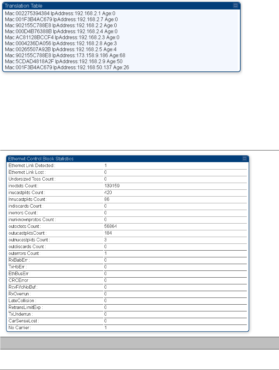
Interpreting Translation Table statistics
When Translation Bridging is enabled in the AP, each SM keeps a table mapping MAC addresses of
devices attached to the AP to IP addresses, as otherwise the mapping of end-user MAC addresses to IP
addresses is lost. (When Translation Bridging is enabled, an AP modifies all uplink traffic originating from
registered SMs such that the source MAC address of every packet is changed to that of the SM which
bridged the packet in the uplink direction.)
Chapter 9: Operation System statistics
Page 9-38
Figure 199 Translation Table page of SM
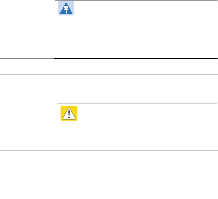
Interpreting Ethernet statistics
The Statistics > Ethernet page reports TCP throughput and error information for the Ethernet connection
of the module. This page is applicable for all modules (AP/SM/BHM/BHS).
The Ethernet page displays the following fields.
Table 224 Ethernet tab attributes
Attribute Meaning
Ethernet Link
Detected
1 indicates that an Ethernet link is established to the radio, 0 indicates that no
Ethernet link is established

Chapter 9: Operation System statistics
Page 9-39
Ethernet Link Lost This field indicates a count of how many times the Ethernet link was lost.
Undersized Toss
Count
This field indicates the number of packets that were too small to process and
hence discarded.
inoctets Count This field displays how many octets were received on the interface, including
those that deliver framing information.
inucastpkts Count This field displays how many inbound subnetwork-unicast packets were
delivered to a higher-layer protocol.
Innucastpkts Count This field displays how many inbound non-unicast (subnetwork-broadcast or
subnetwork-multicast) packets were delivered to a higher-layer protocol.
indiscards Count This field displays how many inbound packets were discarded without errors
that would have prevented their delivery to a higher-layer protocol. (Some of
these packets may have been discarded to increase buffer space.)
inerrors Count This field displays how many inbound packets contained errors that prevented
their delivery to a higher-layer protocol.
inunknownprotos
Count
This field displays how many inbound packets were discarded because of an
unknown or unsupported protocol.
outoctets Count This field displays how many octets were transmitted out of the interface,
including those that deliver framing information.
outucastpkts Count This field displays how many packets for which the higher-level protocols
requested transmission to a subnetwork-unicast address. The number
includes those that were discarded or not sent.
outnucastpkts Count This field displays how many packets for which the higher-level protocols
requested transmission to a non-unicast (subnetwork-broadcast or
subnetwork-multicast) address. The number includes those that were
discarded or not sent.
outdiscards Count This field displays how many outbound packets were discarded without errors
that would have prevented their transmission. (Some of these packets may
have been discarded to increase buffer space.)
outerrrors Count This field displays how many outbound packets contained errors that
prevented their transmission.
RxBabErr This field displays how many receiver babble errors occurred.
TxHbErr This field displays how many transmit heartbeat errors have occurred.
EthBusErr This field displays how many Ethernet bus errors occurred on the Ethernet
controller.
CRCError This field displays how many CRC errors occurred on the Ethernet controller.
RcvFifoNoBuf This field displays the number of times no FIFO buffer space was able to be
allocated.
Chapter 9: Operation System statistics
Page 9-40
Note:
PMP 450 AP running in Gigabit Ethernet Mode displays error
“RcfFifoNoBuf” which indicates packet loss.
For 450 AP platforms, if ethernet auto-negotation is set to
Gigabit, then it is a known limitation that “RcfFifoNoBuf” error will
be seen. This issue is not seen if autonegotation is set to
100Mbps or lower, and the issue is not seen on 450i or 450m
AP's.
RxOverrun This field displays how many receiver overrun errors occurred on the Ethernet
controller.
Late Collision
This field displays how many late collisions occurred on the Ethernet
controller. A normal collision occurs during the first 512 bits of the frame
transmission. A collision that occurs after the first 512 bits is considered a late
collision.
Caution
A late collision is a serious network problem because the frame being
transmitted is discarded. A late collision is most commonly caused by
a mismatch between duplex configurations at the ends of a link
segment.
RetransLimitExp This field displays how many times the retransmit limit has expired.
TxUnderrun This field displays how many transmission-underrun errors occurred on the
Ethernet controller.
CarSenseLost This field displays how many carrier sense lost errors occurred on the
Ethernet controller.
No Carrier This field displays how many no carrier errors occurred on the Ethernet
controller.
Chapter 9: Operation System statistics
Page 9-41
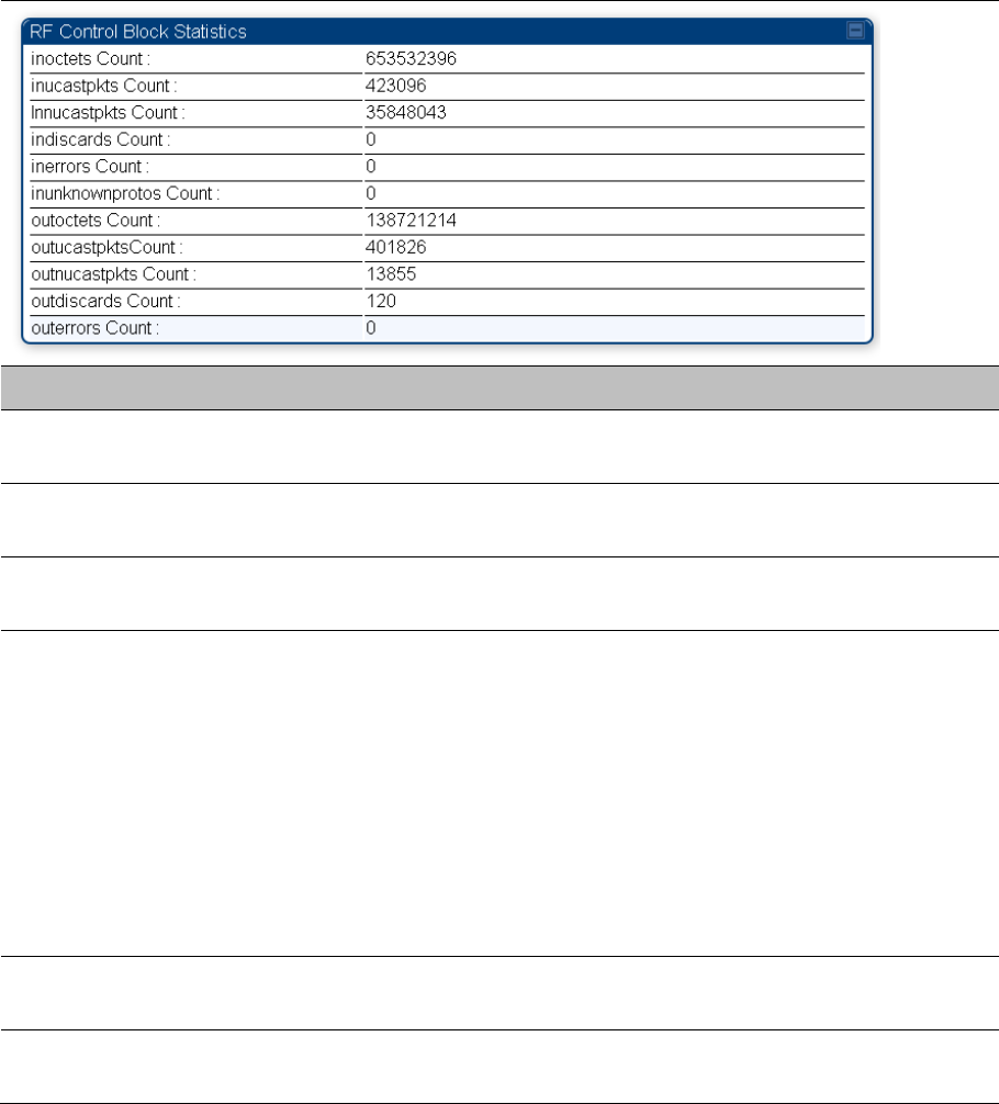
Interpreting RF Control Block statistics
The Statistics > Radio page is applicable for all module (AP/SM/BHM/BHS). The Radio page of the
Statistics page displays the following fields.
Table 225 Radio (Statistics) page attributes – RF Control Block
Attribute Meaning
inoctets Count This field displays how many octets were received on the interface, including
those that deliver framing information.
inucastpkts Count This field displays how many inbound subnetwork-unicast packets were
delivered to a higher-layer protocol.
Innucastpkts Count This field displays how many inbound non-unicast (subnetwork-broadcast or
subnetwork-multicast) packets were delivered to a higher-layer protocol.
indiscards Count This field displays how many inbound packets were discarded without errors
that would have prevented their delivery to a higher-layer protocol. This stat is
pegged whenever corrupt data is received by software or whenever the RF
Software Bridge queue is full.
Corrupt data is a very unusual event because all packets are CRC checked
by hardware before being passed into software.
The likely case for indiscards is if the RF bridge queue is full. If this is the
case the radio is most likely PPS limited due to excessive small packet traffic
or a problem at the Ethernet interface. If there is a problem at the Ethernet
interface there is likely to be discards at the Ethernet as well.
inerrors Count This field displays how many inbound packets contained errors that prevented
their delivery to a higher-layer protocol.
inunknownprotos
Count
This field displays how many inbound packets were discarded because of an
unknown or unsupported protocol.

Chapter 9: Operation System statistics
Page 9-42
outoctets Count This field displays how many octets were transmitted out of the interface,
including those that deliver framing information.
outucastpkts Count This field displays how many packets for which the higher-level protocols
requested transmission to a subnetwork-unicast address. The number
includes those that were discarded or not sent.
outnucastpkts Count This field displays how many packets for which the higher-level protocols
requested transmission to a non-unicast (subnetwork-broadcast or
subnetwork-multicast) address. The number includes those that were
discarded or not sent.
outdiscards Count This field displays how many outbound packets were discarded without errors
that would have prevented their transmission. (Some of these packets may
have been discarded to increase buffer space.)
outerrrors Count This field displays how many outbound packets contained errors that
prevented their transmission.
Page 9-1
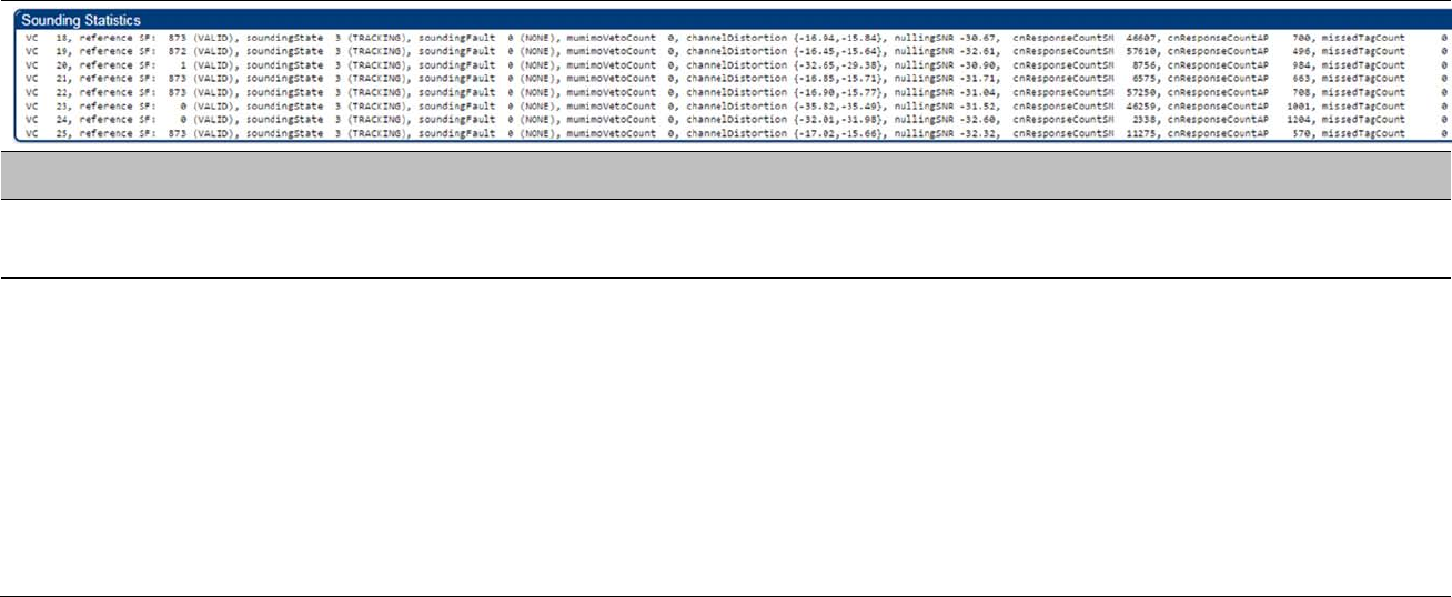
Interpreting Sounding statistics for AP
In the AP GUI, sounding statistics can be found under Statistics > Radio.
Table 226 Radio (Statistics - AP) page attributes - Sounding
Attribute Meaning
reference SF Spatial Frequency of VC. Values 0 to 1023 are valid and value 2048 is considered as invalid.
soundingState Different types of Sounding states are:
UNKNOWN: VC has recently registered to the AP but not registered with the channel manager yet.
NEW: VC has been registered with the channel manager and will soon transition to ASSESSING.
ASSESSING: AP will instruct SM to take the channel measurements. Channel estimates and spatial
frequencies will be calculated.
TRACKING: Valid measurements resulted in good channel estimates and spatial frequency. This VC can
now be used for MU-MIMO.
INVALID: Inconsistent measurements resulting in no channel estimate or spatial frequency. This VC cannot
be used for MU-MIMO and it will ultimately be re-assessed.

Chapter 9: Operation System statistics
Page 9-2
soundingFault Generally if VC is UNTRUSTED, this means something went wrong. The fault codes can help to describe what is
wrong with this channel (If VC is TRACKING this will generally indicate 0 (SOUNDING_FAULT_NONE)).
Error codes are:
SOUNDING_FAULT_VC_CEST: Channel Estimate Error, could be due to issues with the channel..
SOUNDING_FAULT_NULLING_SNR: Channel Estimate Error, could be due to issues with the channel.
SOUNDING_FAULT_SM_ERROR: SM returned Error code when taking channel measurements.
SOUNDING_FAULT_CHANNEL_DISTORTION: Channel Distortion is beyond tolerance, could be due to
issues with the channel.
SOUNDING_FAULT_UNSTABLE_SF: Inconsistent Spatial Frequency, could be due to issues with the
channel.
SOUNDING_FAULT_SF_DEVIATION: Inconsistent Spatial Frequency, could be due to issues with the
channel.
SOUNDING_FAULT_INTERNAL_ERROR: Could be due to incompatible software (AP – SM), or other
catastrophic software issue.
mumimoVetoCount If excessive channel distortion is observed during condensed nulling (tracking state) this count will increment and
VC will transition back to assessing state.
channelDistortion Channel distortion readings.
nullingSNR Signal to noise ratio of condensed nulling error response.
cnResponseCountSM The SM adds a counter to the CN (Condensed Nulling) response. This indicates how many responses were sent
by that SM.
cnResponseCountAP The AP increments a count for each CN response received.
missedTagCount This is the number of CN responses transmitted by SM but not received at AP.
Chapter 9: Operation System statistics
Page 9-3
Page 9-1
Interpreting Sounding statistics for SM
In the SM GUI, sounding statistics can be found under Statistics > Radio.
The top section, RF Control Block Statistics, is applicable to the SM communicating to any AP (450, 450i,
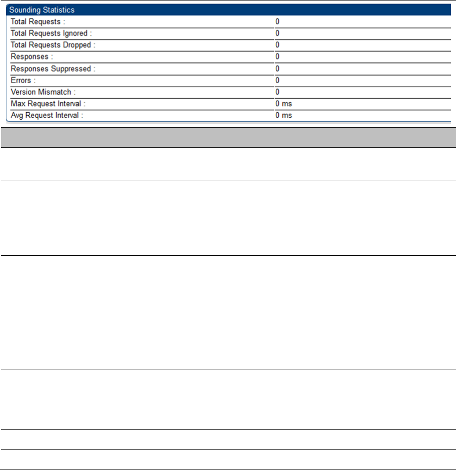
or 450m), and it is always visible. The bottom section, Sounding Statistics, is visible only if the SM is
communicating with a 450m AP.
Table 227 Radio (Statistics - SM) page attributes - Sounding
Attribute Meaning
Responses Number of sounding responses (full VC assessments or condensed nulling)
sent from the SM to the AP
Responses
Suppressed
Number of sounding requests suppressed by the SM.
The reason why a sounding response is suppressed is because the error
calculated during the sounding process is lower than the threshold set by the
AP. In this case, the SM does not need to transmit a sounding response to
the AP
Errors Number of errors in the sounding process at the SM
Examples of events that count as errors:
Sounding type is not supported
IQ capture not enabled: for example, if sounding requested too soon after
SM boot
IQ capture did not complete
Sounding processing took too long
Version Mismatch Number of sounding requests with mismatched version numbers
The Sounding Acquisition Command contains a version number. The SM
checks its own version number and flags any mismatch. Currently, AP and
SMs use V1.
Max Request Interval Largest time between two sounding requests received from the 450m AP
Avg Request Interval Average time between two sounding requests received from the 450m AP
Chapter 9: Operation System statistics
Page 9-2
The following attributes are applicable only for 450m:
Attribute Meaning
mumimoVetoCount If excessive channel distortion is observed during condensed nulling (tracking
state) this count will increment and VC will transition back to assessing state.
channelDistortion Channel distortion readings.
nullingSNR Signal to noise ratio of condensed nulling error response.
cnResponseCountSM The SM adds a counter to the CN (Condensed Nulling) response. This
indicates how many responses were sent by that SM.
cnResponseCountAP The AP increments a count for each CN response received.
missedTagCount This is the number of CN responses transmitted by SM but not received at
AP.
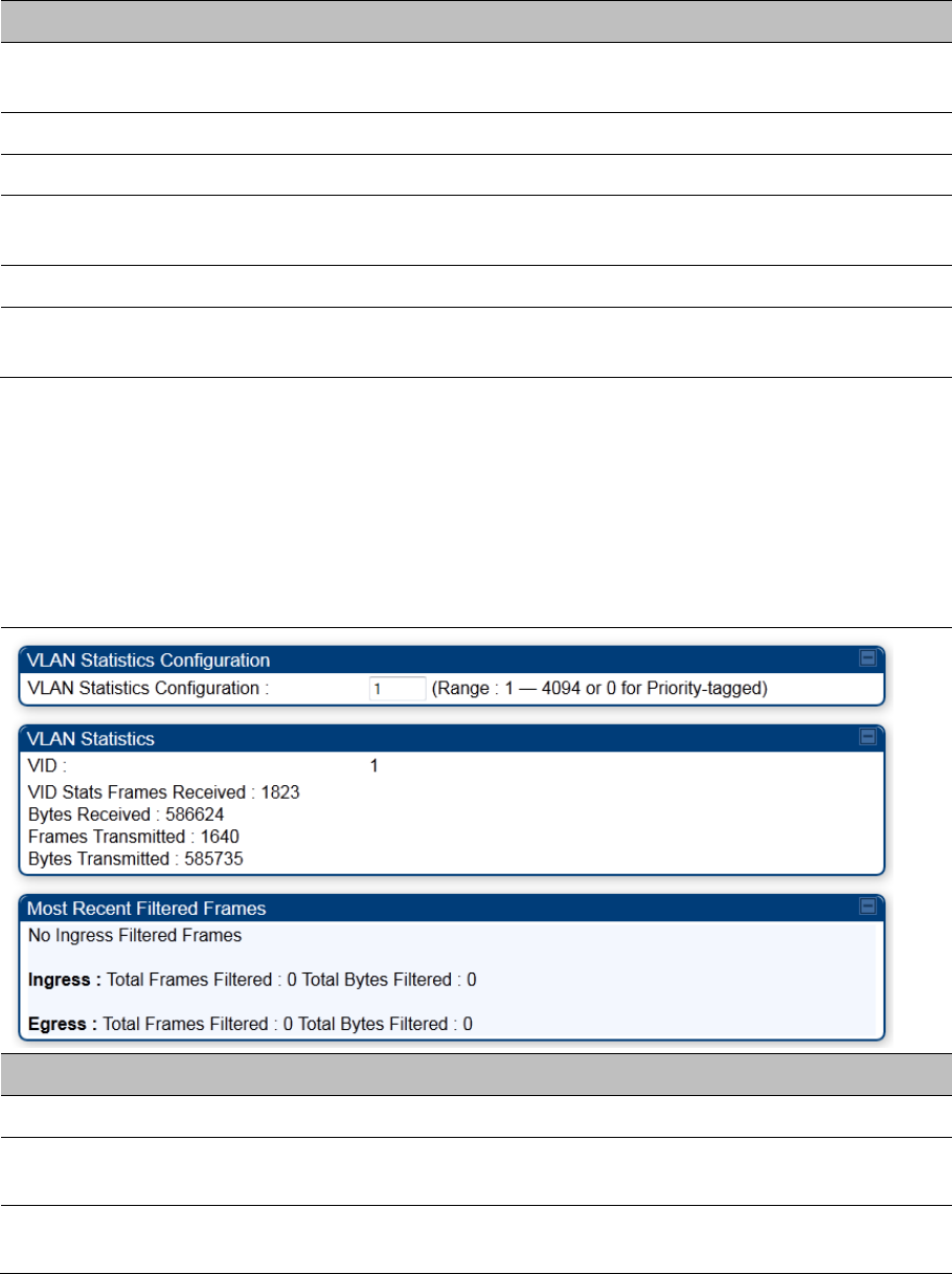
Interpreting VLAN statistics
The Statistics > VLAN page provides a list of the most recent packets that were filtered because of
VLAN membership violations. It is applicable for all modules (AP/SM/BHM/BHS).
Table 228 VLAN page attributes
Attribute Meaning
Unknown This must not occur. Contact Technical Support.
Only Tagged The packet was filtered because the configuration is set to accept only
packets that have an 802.1Q header and this packet did not.
Ingress When the packet entered through the wired Ethernet interface, the packet
was filtered because it indicated an incorrect VLAN membership.

Chapter 9: Operation System statistics
Page 9-3
Local Ingress When the packet was received from the local TCP/IP stack, the packet was
filtered because it indicated an incorrect VLAN membership. This must not
occur. Contact Technical Support.
Egress When the packet attempted to leave through the wired Ethernet interface, the
packet was filtered because it indicated an incorrect VLAN membership.
Local Egress When the packet attempted to reach the local TCP/IP stack, the packet was
filtered because it indicated an incorrect VLAN membership.
Chapter 9: Operation System statistics
Page 9-4
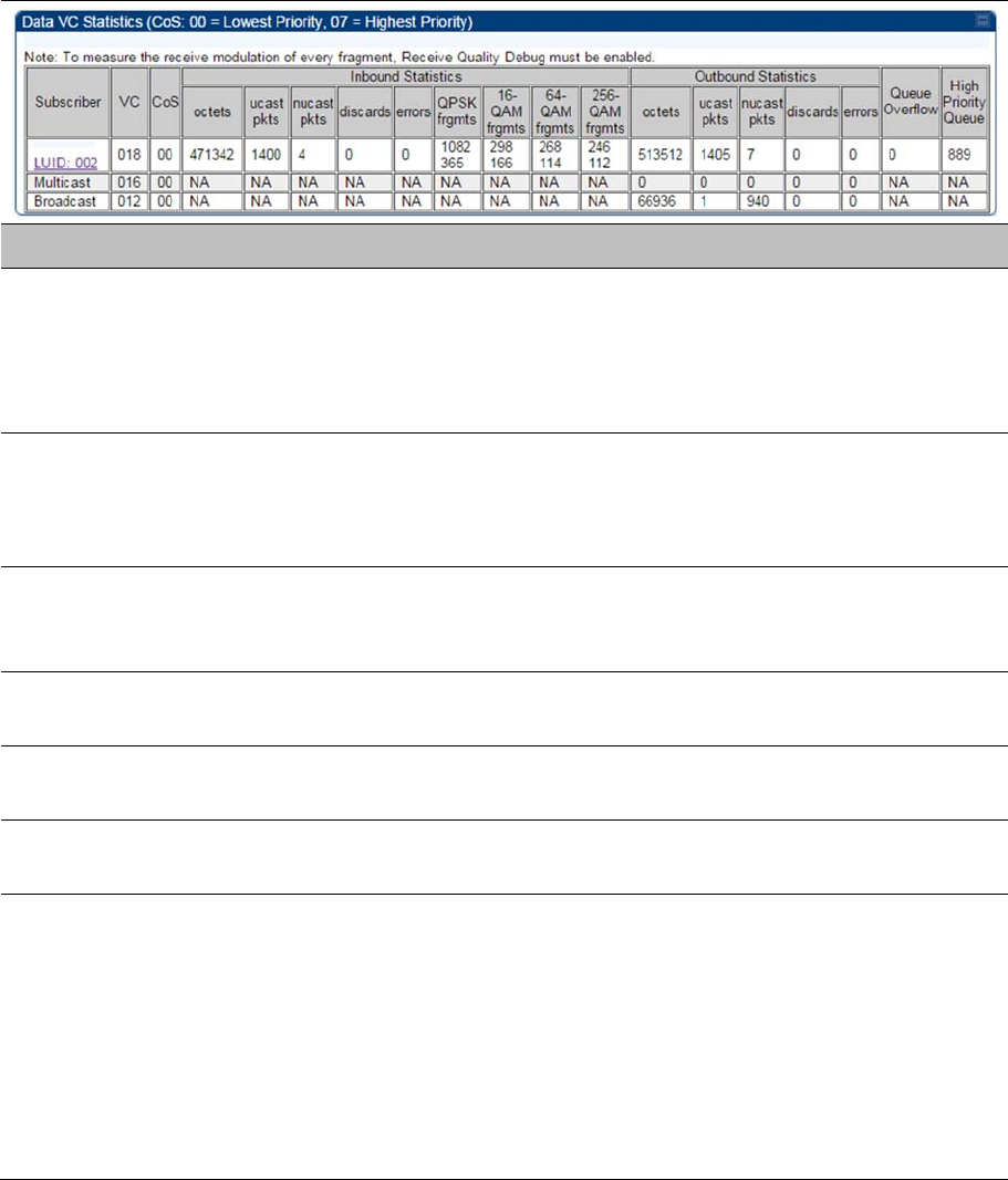
Interpreting Data VC statistics
The Statistics > Data VC page displays information about Virtual Channel (VC) used in data
communications. This page is applicable for all modules (AP/SM/BHM/BHS).
The Data VC tab displays the fields as explained in Table 229.
Table 229 Data VC page attributes
Attribute Meaning
Subscriber This field displays the LUID (logical unit ID), MAC address and Site Name of
the SM/BHS. As each SM or BHS registers to the AP/BHM, the system
assigns an LUID of 2 or a higher unique number to the SM/BHS. If a SM/BHS
loses registration with the AP/BHM and then regains registration, the SM/BHS
retains the same LUID.
VC This field displays the virtual channel number. Low priority channels start at
VC18 and count up. High priority channels start at VC255 and count down. If
one VC is displayed, the high-priority channel is disabled. If two are
displayed, the high-priority channel is enabled.
CoS This field displays the Class of Service for the virtual channel. The low priority
channel is a CoS of 00 and the high priority channel is a CoS of 01. CoS of 02
through 07 are not currently used.
Inbound Statistics,
octets
This field displays how many octets were received on the interface, including
those that deliver framing information.
Inbound Statistics,
ucastpkts
This field displays how many inbound subnetwork-unicast packets were
delivered to a higher-layer protocol.
Inbound Statistics,
nucastpkts
This field displays how many inbound non-unicast (subnetwork-broadcast or
subnetwork-multicast) packets were delivered to a higher-layer protocol.
Inbound Statistics,
discards
This field displays how many inbound packets were discarded without errors
that would have prevented their delivery to a higher-layer protocol. Inbound
discard statistics are incremented similar to the indiscards stat on the RF
control block stats page. The sum of all data VC indiscards must be close to
the RF control block in discards. If indiscards are evenly distributed across
SMs, then the radio is PPS limited due to either excessive small packet
transmissions, or a problem at the Ethernet link. If indiscards are contained to
one or a few SMs, then there is likely a problem at or underneath the SM
which is incrementing the count.

Chapter 9: Operation System statistics
Page 9-5
Inbound Statistics,
errors
This field displays how many inbound packets contained errors that prevented
their delivery to a higher-layer protocol.
Inbound Statistics,
QPSK frgmts
This field displays how many inbound fragments were received via the QPSK
modulation scheme.
Inbound Statistics, 16-
QAM frgmts
This field displays how many inbound fragments were received via the 16-
QAM modulation scheme.
Inbound Statistics, 64-
QAM frgmts
This field displays how many inbound fragments were received via the 64-
QAM modulation scheme.
Inbound Statistics,
256-QAM frgmts
This field displays how many inbound fragments were received via the 256-
QAM modulation scheme.
Outbound Statistics,
octets
This field displays how many octets were transmitted out of the interface,
including those that deliver framing information.
Outbound Statistics,
ucastpkts
This field displays how many packets for which the higher-level protocols
requested transmission to a subnetwork-unicast address. The number
includes those that were discarded or not sent.
Outbound Statistics,
nucastpkts
This field displays how many packets for which the higher-level protocols
requested transmission to a non-unicast (subnetwork-broadcast or
subnetwork-multicast) address. The number includes those that were
discarded or not sent.
Outbound Statistics,
discards
This field displays how many outbound packets were discarded without errors
that would have prevented their transmission. Outbound discard statistics are
incremented if a VC is not active when a packet is ready to send. This is a
rare condition.
Outbound Statistics,
errors
This field displays how many outbound packets contained errors that
prevented their transmission.
Queue Overflow This is a count of packets that were discarded because the queue for the VC
was already full. If Queue Overflows are being seen across most or all SMs,
then there is either an interferer local to the AP or the APs RF link is at
capacity. If Queue Overflows are being seen at one or only a few SMs, then it
is likely that there is a problem with those specific links whether it is
insufficient signal strength, interferer, or a problem with the actual SM
hardware.
High Priority Queue This is a count of packets that were received on high priority queue.
Chapter 9: Operation System statistics
Page 9-6
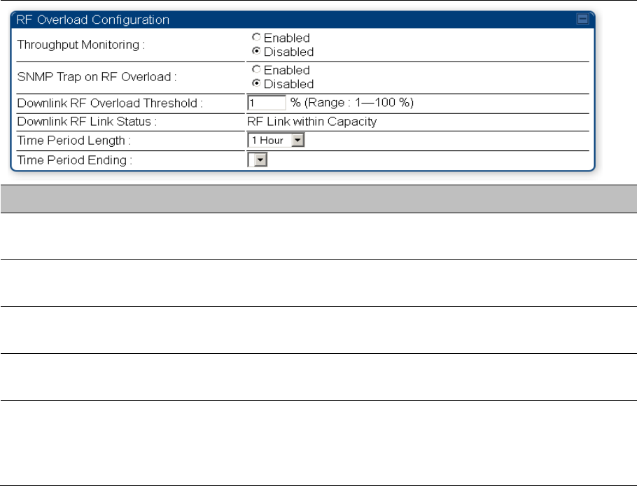
Interpreting Throughput statistics
The 450 Platform Family has a Statistics > Throughput page which shows historical information about
sector or backhaul throughput and packet discards. This page is applicable for AP and BHM modules.
This information can be useful to identify an overloaded sector or heavy bandwidth users. This page also
shows the user throughput in terms of data rate (kbps) and packet rate (packets per second, or PPS), as
well as the average packet size during the sample period.
Operators may set the AP/BHM to send an SNMP trap when it detects an RF overload condition based
on a configurable threshold.
The following configuration parameters are available on the Throughput tab GUI pane and a radio reboot
is not required when configuring these parameters:
Table 230 RF overload Configuration attributes – AP/BHM
Attribute Meaning
Throughput Monitoring This enables or disables the monitoring of sector throughput and packet
discards. This parameter is disabled by default.
SNMP Trap on RF
Overload
This enables or disables the sending of an SNMP trap when an AP/BHM
overload condition is reached (based on Downlink RF Overload Threshold).
Downlink RF Overload
Threshold
This parameter determines the overload threshold in percent of packets
discarded that triggers the generation of an SNMP trap.
Downlink RF Link
Status
This field displays the status of the capacity of the RF link.
Time Period Length
Time Period Ending
These two configuration parameters determine what set of collection samples
to show on the GUI display. The Time Period Length can be set from one to
three hours. Time Period Ending allows the operator to set the end time for
the set of collection samples to display.
Below the configuration settings are three tables that display the statistics that are collected.
Board Performance statistics
This table contains a row that corresponds to each 1 minute statistics collection interval. Each row
contains the following data aggregated for the entire AP/BHM:
Chapter 9: Operation System statistics
Page 9-7
Ethernet Throughput - Statistics collected at the Ethernet port:
o kbps in – average throughput over the collection interval in Kbps into the AP/BHM on the
Ethernet Interface
o kbps out – average throughput over the collection interval in Kbps out of the AP/BHM on the
Ethernet Interface
o PPS in – average packets per second over the collection interval into the AP/BHM on the
Ethernet Interface
o PPS out – average packets per second over the collection interval out of the AP/BHM on the
Ethernet Interface
RF Throughput - Statistics collected at the RF Interface:
o kbps in – average throughput over the collection interval in Kbps into the AP/BHM on the RF
Interface
o kbps out – average throughput over the collection interval in Kbps out of the AP/BHM on the RF
Interface
o PPS in – average packets per second over the collection interval into the AP/BHM on the RF
Interface
o PPS out – average packets per second over the collection interval out of the AP/BHM on the RF
Interface
Aggregate Through Board – Sum of bidirectional data transferred through (not originating or
terminating at) the AP/BHM:
o kbps – average bidirectional throughput over the collection interval in Kbps
o PPS – average bidirectional packets per second over the collection interval
o Ave Pkt Size – Average Packet size over the collection interval of bidirectional data transferred
Board Throughput statistics
This table contains a row that corresponds to each one minute statistics collection interval. This table may
be used to determine if there are problems with any of the interfaces. For example, if the Ethernet in
packets is much higher than the RF out packets it could indicate a denial of service (DoS) attack on the
AP/BHM. Each row contains the following data aggregated for the entire AP/BHM:
Ethernet Statistics - Statistics collected at the Ethernet port:
o inOctets – Number of octets (bytes) received by the AP/BHM at the Ethernet Interface over the
collection interval
o outOctets – Number of octets (bytes) sent by the AP/BHM at the Ethernet Interface over the
collection interval
o inPkts – Number of packets received by the AP/BHM at the Ethernet Interface over the collection
interval
o outPkts – Number of packets sent by the AP/BHM at the Ethernet Interface over the collection
interval
o Discards (in/out) – Number of packets that had to be discarded by the AP/BHM at the respective
Ethernet Interface Queue
RF Statistics - Statistics collected at the RF Interface:
o inOctets – Number of octets (bytes) received by the AP/BHM at the RF Interface over the
collection interval
o outOctets – Number of octets (bytes) sent by the AP/BHM at the RF Interface over the collection
interval
o inPkts – Number of packets received by the AP/BHM at the RF Interface over the collection
interval
Chapter 9: Operation System statistics
Page 9-8
o outPkts – Number of packets sent by the AP/BHM at the RF Interface over the collection interval
o Discards (in/out) – Number of packets that had to be discarded by the AP/BHM at the respective
RF Interface Queue during the collection interval
o Discards % (in/out) – Percent of the total packets received / transmitted that had to be discarded
during the collection interval
LUID RF Throughput statistics
This table contains a row that corresponds to each active LUID served by the AP/BHM. Note that an LUID
may be assigned 1 or 2 VCs. If the LUID is assigned 2 VCs, then the data in the table is the sum of the
activity for both VCs. This table may be used to determine which LUIDs are experiencing overload so that
corrective action can be taken (i.e. fixing a poor RF link or moving a heavily loaded link to a less
congested AP/BHM). Each row contains counters and statistics related to the RF Interface that are
updated once per minute:
Inbound Statistics - Statistics collected at the RF Interface for the Uplink:
o octets – Number of octets (bytes) received by the AP/BHM at the RF Interface for this LUID over
the collection interval
o pkts – Number of packets received by the AP/BHM at the RF Interface for this LUID over the
collection interval
o Ave Pkt Size – Average size of the packets received by the AP/BHM at the RF Interface for this
LUID over the collection interval
o discards – Number of packets received by the AP/BHM at the RF Interface for this LUID over the
collection interval that had to be discarded because the RF In Queue was full
o discards % – Percent of the total packets received by the AP/BHM at the RF Interface for this
LUID over the collection interval that had to be discarded because the RF In Queue was full
Outbound Statistics - Statistics collected at the RF Interface for the Downlink:
o octets – Number of octets (bytes) transmitted by the AP/BHM at the RF Interface for this LUID
over the collection interval
o pkts – Number of packets transmitted by the AP/BHM at the RF Interface for this LUID over the
collection interval
o Ave Pkt Size – Average size of the packets transmitted by the AP/BHM at the RF Interface for
this LUID over the collection interval
o discards – Number of packets to be transmitted by the AP/BHM at the RF Interface for this LUID
over the collection interval that had to be discarded because the RF Out Queue was full
o discards % – Percent of the total packets to be transmitted by the AP/BHM at the RF Interface
for this LUID over the collection interval that had to be discarded because the RF Out Queue was
full.
Chapter 9: Operation System statistics
Page 9-9
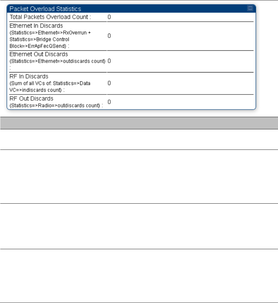
Interpreting Overload statistics
The Statistics > Overload page displays statistics on packet overload and resultant packet discards.
Unlike the other fields, the Total Packets Overload Count is expressed in only this page. It is not a count
of how many packets have been lost, but rather of how many discard events (packet loss bursts) have
been detected due to overload condition.
This statistics page is applicable for all modules (AP/SM/BHM/BHS) and explained in Table 231.
Table 231 Overload page attributes – AP/SM/BHM/BHS
Attribute Meaning
Total Packets
Overload Count
This field represents the sum of all RF and Ethernet in/out discards.
Ethernet In Discards This field represents the number of packets tossed due to the Ethernet queue
being full. If a climb in this stat accompanies a climb in RF Out Discards stat,
then most likely the board is at RF capacity either due to traffic exceeding the
RF pipe, or interference temporarily limiting the RF throughput. If this stat
climbs without the RF Out Discards stat climbing, then the radio is most likely
PPS limited.
Ethernet Out Discards This field represents the number of packets tossed due to an Ethernet out
overload. This stat must not climb in normal operation because the Ethernet
link is much higher capacity than the RF link. If this stat is incrementing, then
either the Ethernet link is established at a low speed (i.e. 10Mbps – half
duplex), or there is a problem with cabling/Ethernet hardware.
RF In Discards This field indicates the number of packets tossed due to no resources
available within the radio to process them. This stat also must not be
increasing because the system is designed to shed packets on the RF Out
interface. If this stat is incrementing the board, it is most likely congested due
to high PPS rate in combination with an Ethernet Out problem, which limits
packet flow off the device.
Chapter 9: Operation System statistics
Page 9-10
RF Out Discards This field indicates the number of packets tossed due to RF link at capacity.
This stat will increase whenever the RF link is at capacity. When the internal
FPGA RF input queue overflows, this stat is incremented. If this stat is seen
to be incrementing at the AP, then the sector is congested. If seen at the SM,
the number of Contention Slots must be looked at to ensure that enough
Contention Slots are allocated to allow for bandwidth requests to be seen at
the AP.
Note
450m Overload:
The 450m Series AP is designed to handle high load in terms of high throughput and high
PPS. In terms of throughput, 450m is designed to achieve 3x or more throughput
improvement over 450 and 450i Series products. In terms of packets per second (PPS),
450m is designed to handle up to 100k PPS.
Overload occurs when the offered load exceeds the above limits. When overload occurs,
450m will start discarding packets and TCP throughput will degrade due to packet loss.
It’s worth noting that Frame Utilization statistics (Statistics > Frame Utilization tab: Frame
Utilization: Downlink and Uplink) are not necessarily indicative of overload condition. They
show how much the TDD frame is utilized. High frame utilization depends on:
High traffic during busy periods: those statistics will be close to 100% and almost all
slots will be utilized. In this case if the Overload statistics show that packets are
discarded then this is an indication of overload condition.
High percentage of VCs with low modulation with moderate traffic. Those VCs will
require more slots to service them (due to low modulation) and the frame utilization will
be high. In this case the TDD frame is fully utilized but the system is at low capacity and
is not in an overload condition.
450m has higher PPS than 450 and 450i and supports higher throughput through spatial
multiplexing, therefore when a 450m replaces an overloaded 450 or 450i AP the 450m will
not be overloaded under the same conditions but the frame utilization may still show close to
100%; this should not alarm the customer. The overload statistics shall be monitored on
450m to see if it is overloaded or not.
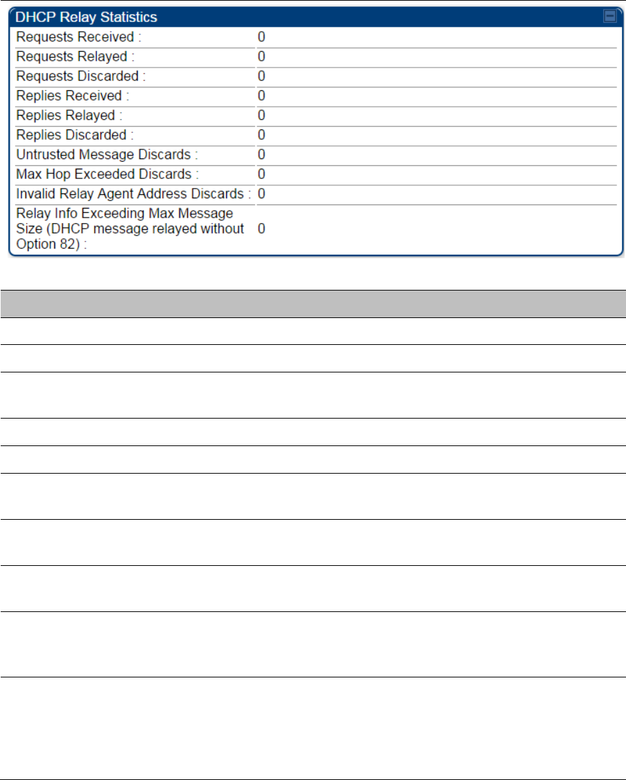
Interpreting DHCP Relay statistics
The Statistics > DHCP Relay page displays requests and replies received, relayed and discarded when
the AP is configured as a DHCP relay. Typically, in a working DHCP relay configuration a one-to-one ratio
is established between requests and replies that are received and relayed. This statistics page is only
applicable for PMP (AP and SM modules) and it is explained in Table 232.
Chapter 9: Operation System statistics
Page 9-11
Table 232 DHCP Relay page attributes – AP/SM
Attribute Meaning
Requests Received This field represents the number of DHCP relay requests received by the AP.
Requests Relayed This field represents the number of DHCP relay requests relayed by the AP.
Requests Discarded This field represents the number of DHCP relay requests discarded by the AP
due to errors in the request.
Replies Received This field represents the number of DHCP relay replies received by the AP.
Replies Relayed This field represents the number of DHCP relay replies relayed by the AP.
Replies Discarded This field represents the number of DHCP relay replies discarded by the AP
due to errors in the reply.
Untrusted Message
Discards
This field indicates messages that were discarded because the message
already contained Option 82 information with no Relay Agent specified.
Max Hop Exceeded
Discards
This field indicates messages that have been relayed too many times,
exceeding the max hop count (16).
Invalid Relay Agent
Address Discards
This field indicates messages that have been discarded because the
message relay agent address is already in place (relay agent address does
not equal address of the AP).
Relay Info Exceeding
Max Message Size
(DHCP message
relayed without Option
82)
This field indicates DHCP messages too large to fit Option 82 data. These
messages are sent on without Option 82 information.
Chapter 9: Operation System statistics
Page 9-12
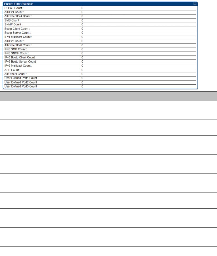
Interpreting Filter statistics
The Statistics > Filter page displays statistics on packets that have been filtered (dropped) due to the
filters set on the Protocol Filtering page. The filter page of SM is explained in Table 233.
Table 233 Filter page attributes - SM
Attribute Meaning
PPPoE Count Number of PPPoE packets filtered.
All IPv4 Count Number of IPv4 packets filtered.
All Other IPv4 Count Any IPv4 message that was not SMB, SNMP, Bootp, Multicast or one of
the user defined filters, that was filtered out.
SMB Count Number of IPv4 Server Message Block (file sharing) packets filtered.
SNMP Count Number of IPv4 SNMP packets filtered.
Bootp Client Count Total number of IPv4 DHCP requests filtered.
Bootp Server Count Total number of IPv4 DHCP replies filtered.
IPv4 Multicast Count Number of IPv4 Multicast messages filtered.
All IPv6 Count Number of IPv6 messages filtered.
All Other IPv6 Count Any IPv6 message that was not SMB, SNMP, Bootp, Multicast or one of
the user defined filters, that was filtered out.
IPv6 SMB Count Number of IPv6 Server Message Block (file sharing) packets filtered
IPv6 SNMP Count Number of IPv6 SNMP messages filtered
IPv6 Bootp Client Count Total number of IPv6 DHCP replies filtered
IPv6 Bootp Server Count Total number of IPv6 DHCP replies filtered
IPv6 Multicast Count Number of IPv6 Multicast messages filtered
Chapter 9: Operation System statistics
Page 9-13
ARP Count Total number of ARP packets filtered.
All other Count The count of any messages that did not fit above that were filtered out
User Defined Port1 Count Number of packets defined by the user port1 that were filtered.
User Defined Port2 Count Number of packets defined by the user port2 that were filtered.
User Defined Port3 Count Number of packets defined by the user port3 that were filtered.
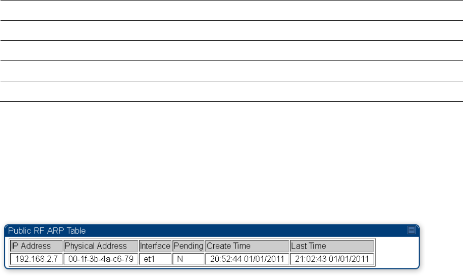
Viewing ARP statistics
The Statistics > ARP page in a SM module correlated the IP address of the Ethernet-connected device
to its MAC address and provides data about the connection.
Figure 200 ARP page of the SM
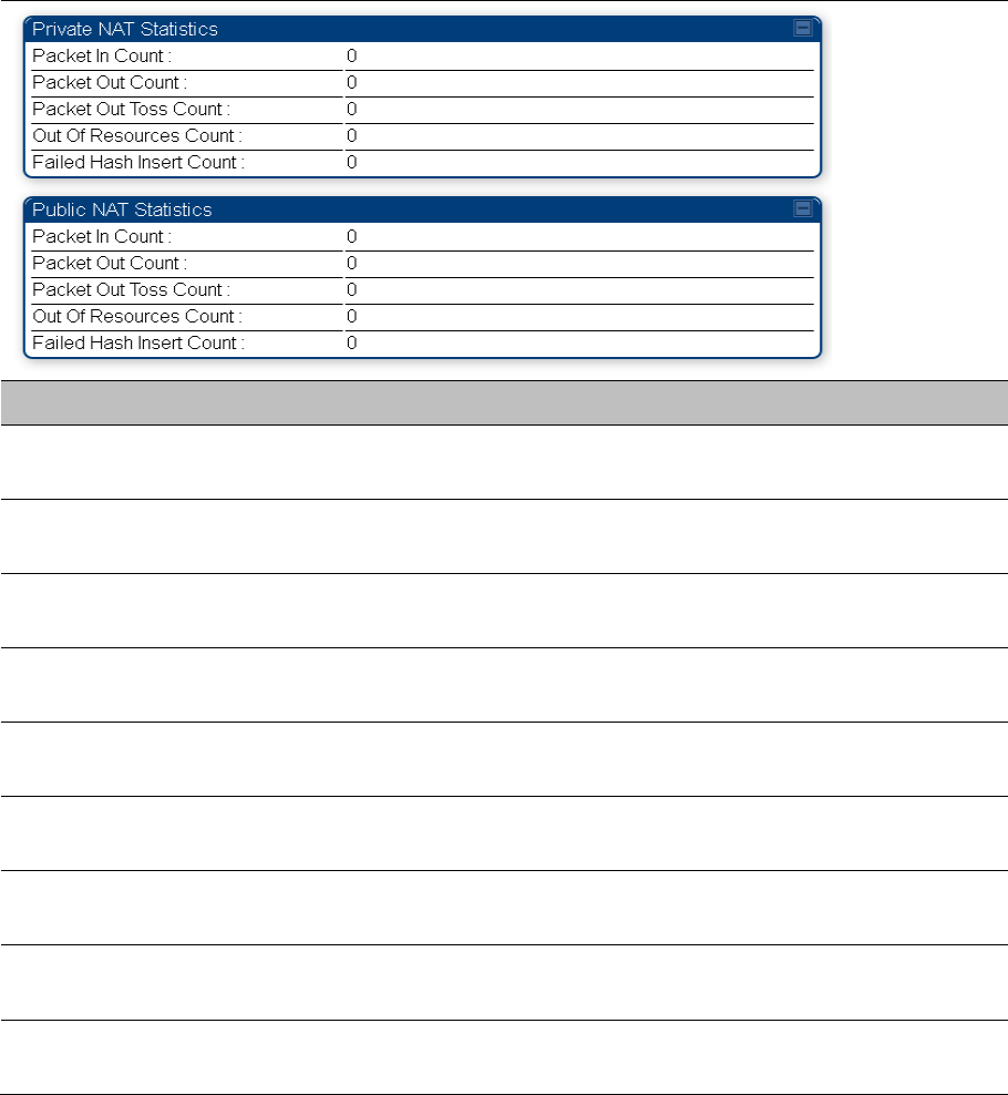
Viewing NAT statistics
When NAT is enabled on a SM, statistics are kept on the Public and Private (WAN and LAN) sides of the
NAT and displayed on the Statistics > NAT Stats page. The NAT page of SM is explained in Table 234.
Chapter 9: Operation System statistics
Page 9-14
Table 234 NAT page attributes - SM
Attribute Meaning
Private NAT Statistics,
Packet In Count
This field represents the number of packets received on the SM’s
LAN/Ethernet interface
Private NAT Statistics,
Packet Out Count
This field represents the number of packets sent from the SM’s
LAN/Ethernet interface
Private NAT Statistics,
Packet Out Toss Count
This field represents the number of packets that we not sent from the
SM’s LAN/Ethernet interface due to addressing issues.
Private NAT Statistics,
Out of Resources Count
This field represents the number of times the NAT table for the SM’s
LAN/Ethernet interfaces has been filled.
Private NAT Statistics,
Failed Hash Insert Count
This field represents the number of times that the device failed to insert an
address binding into the NAT hash table.
Public NAT Statistics,
Packet In Count
This field represents the number of packets received on the SM’s
WAN/wireless interface
Public NAT Statistics,
Packet Out Count
This field represents the number of packets sent from the SM’s
WAN/wireless interface
Public NAT Statistics, Out
of Resources Count
This field represents the number of packets that we not sent from the
SM’s WAN/wireless interface due to addressing issues.
Public NAT Statistics,
Failed Hash Insert Count
This field represents the number of times the NAT table for the SM’s
WAN/wireless interfaces has been filled.
Chapter 9: Operation System statistics
Page 9-15
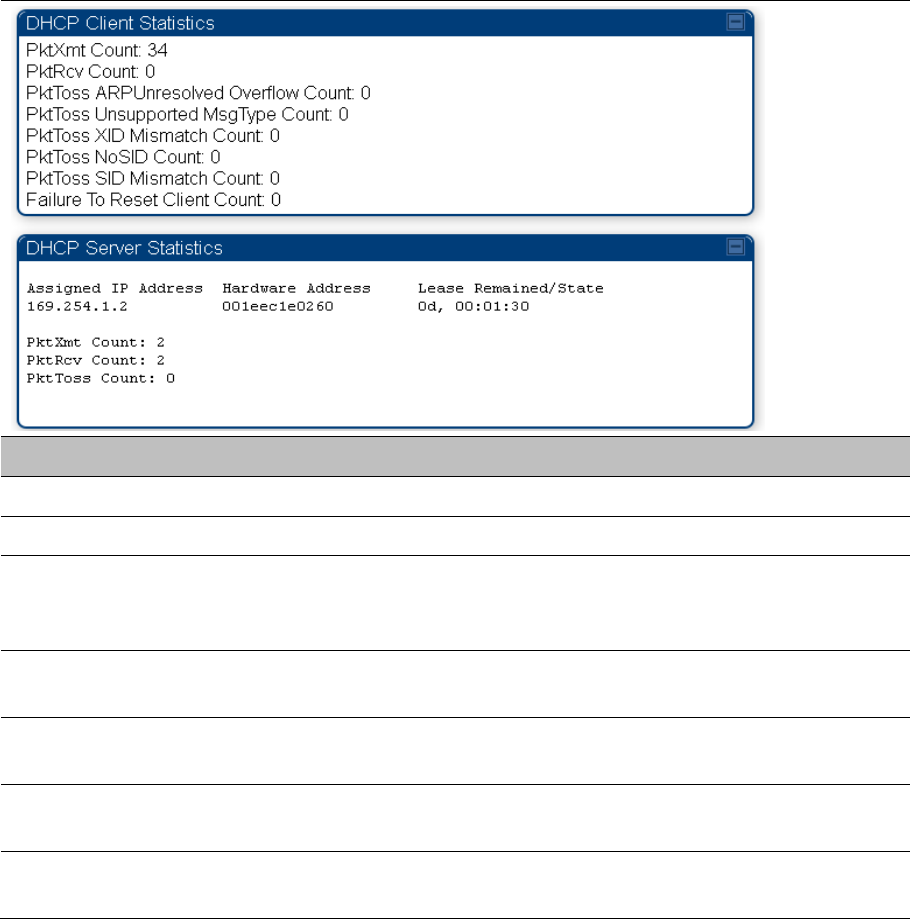
Viewing NAT DHCP Statistics
The Statistics > NAT DHCP page displays NAT enabled DHCP client statistics. This is statistics page is
applicable for SM only.
When NAT is enabled on a SM with DHCP client (DHCP selected as the Connection Type of the WAN
interface) and/or DHCP Server, statistics are kept for packets transmitted, received and tossed, as well as
a table of lease information for the DHCP server (Assigned IP Address, Hardware Address and Lease
Remained/State).
Table 235 NAT DHCP Statistics page attributes - SM
Attribute Meaning
PktXmt Count Represents the number of DHCP packets transmitted from the client
PktRcv Count This field represents the number of DHCP packets received by the client
PktToss
ARPUnresolved
Overflow Count
This field represents the number of packets tossed due to failed attempts to
resolve an IP address into a physical MAC address
PktToss Unsupported
MsgType Count
This field represents the number of packets tossed due to the receipt of an
unsupported message type (cannot be interpreted by DHCP client)
PktToss XID
Mismatch Count
The field represents the number of packets that were tossed due to a
transaction ID mismatch
PktToss NoSID Count This field represents the number of packets that were tossed due to lack of a
DHCP session ID
PktToss SID
Mismatch Count
Represents the number of packets tossed due to a session ID mismatch
Chapter 9: Operation System statistics
Page 9-16
Failure to Reset Client
Count
This field represents the number of times the DHCP client was unable to be
reset (resulting in no IP address being served).
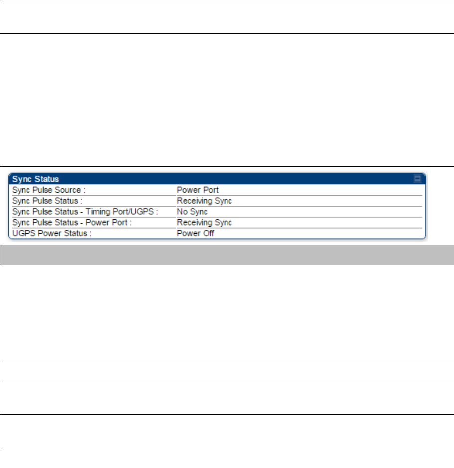
Interpreting Sync Status statistics
The Statistics > Sync Status page of AP is only displayed when the Sync Input is set to AutoSync or
AutoSync+Free Run.
The Sync Status page is explained in Table 236.
Table 236 Sync Status page attributes - AP
Attribute Meaning
Sync Pulse Source This field indicates the status of the synchronization source:
Searching indicates that the unit is searching for a GPS fix
Timing Port/UGPS indicates that the module is receiving sync via the
timing AUX/SYNC timing port
Power Port indicates that the module is receiving sync via the power port
(Ethernet port).
Sync Pulse Status This field indicates synchronization source pulse status.
Sync Pulse Status –
Timing Port/UGPS
This field indicates synchronization pulse status over Timing Port/UGPS port.
Sync Pulse Status -
Power Port
This field indicates synchronization pulse status over power port.
UGPS Power Status This field indicates UGPS power up status (on or off).
This information may be helpful in a decision of whether to climb a tower to diagnose a perceived antenna
problem.
Chapter 9: Operation System statistics
Page 9-17
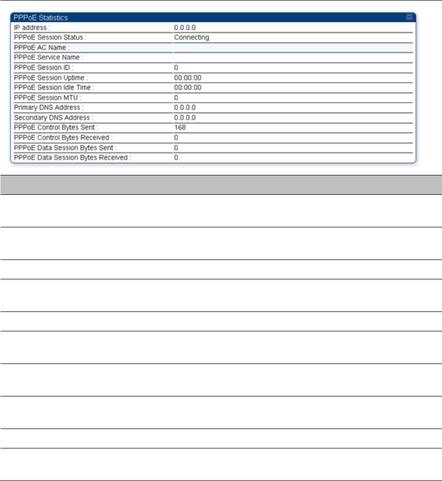
Interpreting PPPoE Statistics for Customer Activities
The page can be access under Statistics > PPPoE of SM GUI.
When the PPPoE feature is enabled on the SM, PPPoE statistics provide data about activities of the
customer.
The PPPoE Statistics of SM is explained in Table 237.
Table 237 PPPoE Statistics page attributes - SM
Attribute Meaning
IP address This field displays the IP address of the PPPoE session initiator (situated
below the SM)
PPPoE Session
Status
This field displays the operational status of the PPPoE Session
PPPoE AC Name This field displays access concentrator name used in the PPPoE session
PPPoE Service Name This field displays the PPPoE service name associated with the PPPoE
server in use
PPPoE Session ID This field displays the current PPPoE session ID
PPPoE Session
Uptime
This field displays the total session uptime for the PPPoE session
PPPoE Session Idle
Time
This field displays the total idle time for the PPPoE session
PPPoE Session MTU This field displays Maximum Transmission Unit configured for the PPPoE
session
Primary DNS Address This field displays the primary DNS server used by the PPPoE session
Secondary DNS
Address
This field displays the secondary DNS server used by the PPPoE session

Chapter 9: Operation System statistics
Page 9-18
PPPoE Control Bytes
Sent
Displays the total number of PPPoE session control bytes sent from SM
PPPoE Control Bytes
Received
This field displays the total number of PPPoE session control bytes received
by the SM
PPPoE Data Session
Bytes Sent
This field displays the total number of PPPoE data session (non-control/non-
session management user data) sent by the SM
PPPoE Data Session
Bytes Received
This field displays the total number of PPPoE data session (non-control/non-
session management user data)
Chapter 9: Operation System statistics
Page 9-19
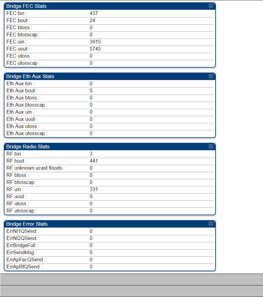
Interpreting Bridge Control Block statistics
The Statistics > Bridge Control Block page displays statistics of Bridge FEC, Bridge ratio and Bridge
error. The page is applicable for all modules (AP/SM/BHM/BHS). The Bridge Control Block Statistics page
is explained in Table 238.
Table 238 Bridge Control Block page attributes – AP/SM/BHM/BHS
Attribute Meaning
Bridge FEC Stats

Chapter 9: Operation System statistics
Page 9-20
FEC bin This field indicates the number of broadcast packets received by the bridge
control block on the Main Ethernet interface
FEC bout This field indicates the number of broadcast packets sent by the bridge
control block on the Main Ethernet interface
FEC btoss This field indicates the number of broadcast packets tossed out by the bridge
control block on the Main Ethernet interface
FEC btosscap This field indicates the number of broadcast packets tossed out at the Main
Ethernet interface due to MIR cap being exceeded.
FEC uin This field indicates the number of unicast packets received by the bridge
control block on the Main Ethernet interface
FEC uout This field indicates the number of unicast packets sent by the bridge control
block on the Main Ethernet interface
FEC utoss This field indicates the number of unicast packets tossed by the bridge control
block on the Main Ethernet interface
FEC utosscap This field indicates the number of unicast packets tossed out at the Main
Ethernet interface due to MIR cap being exceeded.
Bridge Eth Aux Stats
FEC bin This field indicates the number of broadcast packets received by the bridge
control block on the Aux Ethernet interface
FEC bout This field indicates the number of broadcast packets sent by the bridge
control block on the Aux Ethernet interface
FEC btoss This field indicates the number of broadcast packets tossed out by the bridge
control block on the Aux Ethernet interface
FEC btosscap This field indicates the number of broadcast packets tossed out at the Aux
Ethernet interface due to MIR cap being exceeded.
FEC uin This field indicates the number of unicast packets received by the bridge
control block on the Aux Ethernet interface
FEC uout This field indicates the number of unicast packets sent by the bridge control
block on the Aux Ethernet interface
FEC utoss This field indicates the number of unicast packets tossed by the bridge control
block on the Aux Ethernet interface
FEC utosscap This field indicates the number of unicast packets tossed out at the Aux
Ethernet interface due to MIR cap being exceeded.
Bridge Radio Stats
RF bin This field indicates the number of broadcast packets received by the bridge
control block on the radio interface

Chapter 9: Operation System statistics
Page 9-21
RF bout This field indicates the number of broadcast packets sent by the bridge
control block on the radio interface
RF btoss This field indicates the number of broadcast packets tossed by the bridge
control block on the radio interface
RF btosscap This field indicates the number of broadcast packets tossed out at the radio
interface due to MIR cap being exceeded.
RF uin This field indicates the number of unicast packets received by the bridge
control block on the radio interface
RF uout This field indicates the number of unicast packets sent by the bridge control
block on the radio interface
RF utoss This field indicates the number of unicast packets tossed by the bridge control
block on the radio interface
RF utosscap This field indicates the number of unicast packets tossed out at the radio
interface due to MIR cap being exceeded.
Bridge Error Stats
ErrNI1QSend This field indicates that a packet which was sourced from the radio network
stack interface 1 (Ethernet interface) could not be sent because the radio
bridge queue was full. The packet was tossed out.
ErrNI2QSend This field indicates that a packet which was sourced from the radio network
stack interface 2 (RF interface) could not be sent because the radio bridge
queue was full. The packet was tossed out.
ErrBridgeFull This field indicates the total number of times the bridging table was full and
could not accept new entries.
ErrSendMsg This field displays the error message from bridge core call back routine.
ErrApFecQSend This field indicates that a packet which was received on the Ethernet interface
could not be processed because the radio bridge queue was full and packet
was tossed out.
ErrApRfQSend This field indicates that a packet which was received on the RF interface
could not be processed because the radio bridge queue was full. The packet
was tossed out.
Note:
PMP 450m Series AP does not support Aux port in current release of 15.0/15.0.0.1.
Chapter 9: Operation System statistics
Page 9-22
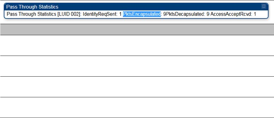
Interpreting Pass Through Statistics
The Statistics > Pass Through Statistics page displays radius related statistics. The page is applicable
for PMP 450 Platform Family - AP only. The Pass Through Statistics page is explained in Table 239.
Table 239 Pass Through Statistics page attributes – AP
Attribute Meaning
IdentityReqSent This field indicates the number of EAP Identity requests sent through
the AP with respect to an SM.
PktsEncapsulated This field indicates no of packets received from the SM which are
encapsulated by the AP.
PktsDecasulated This field indicates no of packets received from the radius server and
are decapsulated by the AP with respect to an SM
AccessAcceptRcvd This field indicates no of RADIUS Access Accept message received
by the AP with respect to an SM.
Chapter 9: Operation System statistics
Page 9-23
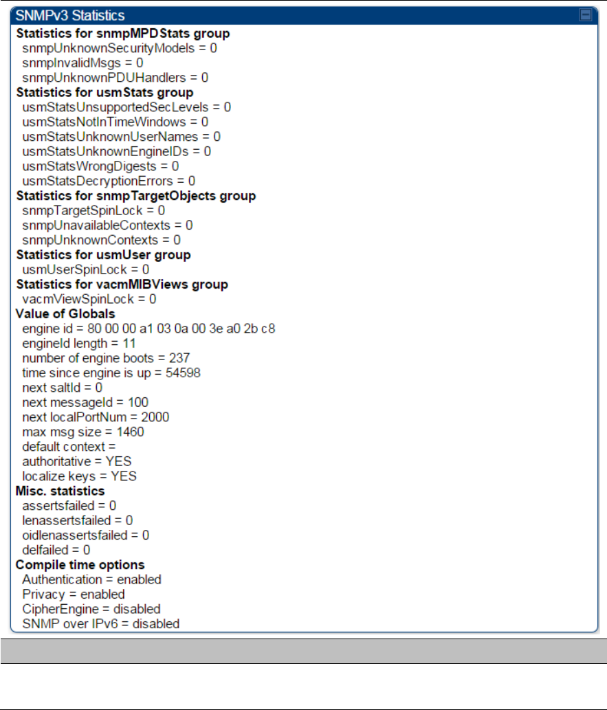
Interpreting SNMPv3 Statistics
The Statistics > SNMPv3 Statistics page displays all SNMPv3 related statistics. The page is applicable
for all type of ODUs of PMP 450 Platform. The SNMPv3 Statistics page is explained in Table 240.
Table 240 SNMPv3 Statistics page attributes – AP
Attribute Meaning
Statistics for
snmpMPDStats group SNMP Message Processing and Dispatching RFC 3412

Chapter 9: Operation System statistics
Page 9-24
snmpUnknownSecurityMod
els
The total number of packets received by the SNMP engine which
were dropped because they referenced a securityModel that was not
known to or supported by the SNMP engine.
snmpInvalidMsgs The total number of packets received by the SNMP engine which
were dropped because there were invalid or inconsistent components
in the SNMP message.
snmpUnknownPDUHandler
s
The total number of packets received by the SNMP engine which
were dropped because the PDU contained in the packet could not be
passed to an application responsible for handling the pduType, e.g.
no SNMP application had registered for the proper combination
of the contextEngineID and the pduType.
usmStatsUnsupportedSecL
evels
The total number of packets received by the SNMP engine which
were dropped because they requested a securityLevel that was
unknown to the SNMP engine or otherwise unavailable.
usmStatsNotInTimeWindow
s
The total number of packets received by the SNMP engine which
were dropped because they appeared outside of the authoritative
SNMP engine's window.
usmStatsUnknownUserNa
mes
The total number of packets received by the SNMP engine which
were dropped because they referenced a user that was not known to
the SNMP engine.
usmStatsUnknownEngineI
Ds
The total number of packets received by the SNMP engine which
were dropped because they referenced a snmpEngineID that was not
known to the SNMP engine.
usmStatsWrongDigests The total number of packets received by the SNMP engine which
were dropped because they didn't contain the expected digest value.
usmStatsDecryptionErrors The total number of packets received by the SNMP engine which
were dropped because they could not be decrypted.
snmpTargetSpinLock This object is used to facilitate modification of table entries in the
SNMP-TARGET-MIB module by multiple managers.
snmpUnavailableContexts The total number of packets received by the SNMP engine which
were dropped because the context contained in the message was
unavailable.
snmpUnknownContexts The total number of packets received by the SNMP engine which
were dropped because the context contained in the message was
unknown.
usmUserSpinLock The use of usmUserSpinlock is to avoid conflicts with another SNMP
command generator application which may also be acting on the
usmUserTable.
Chapter 9: Operation System statistics
Page 9-25
vacmViewSpinLock An advisory lock used to allow cooperating SNMP Command
Generator applications to coordinate their use of the Set operation in
creating or modifying views.
snmpEngineBoots It is a count of the number of times the SNMP engine has re-
booted/re-initialized since snmpEngineID was last configured
snmpEngineTime
time since engine is up
which is the number of seconds since the snmpEngineBoots counter
was last incremented
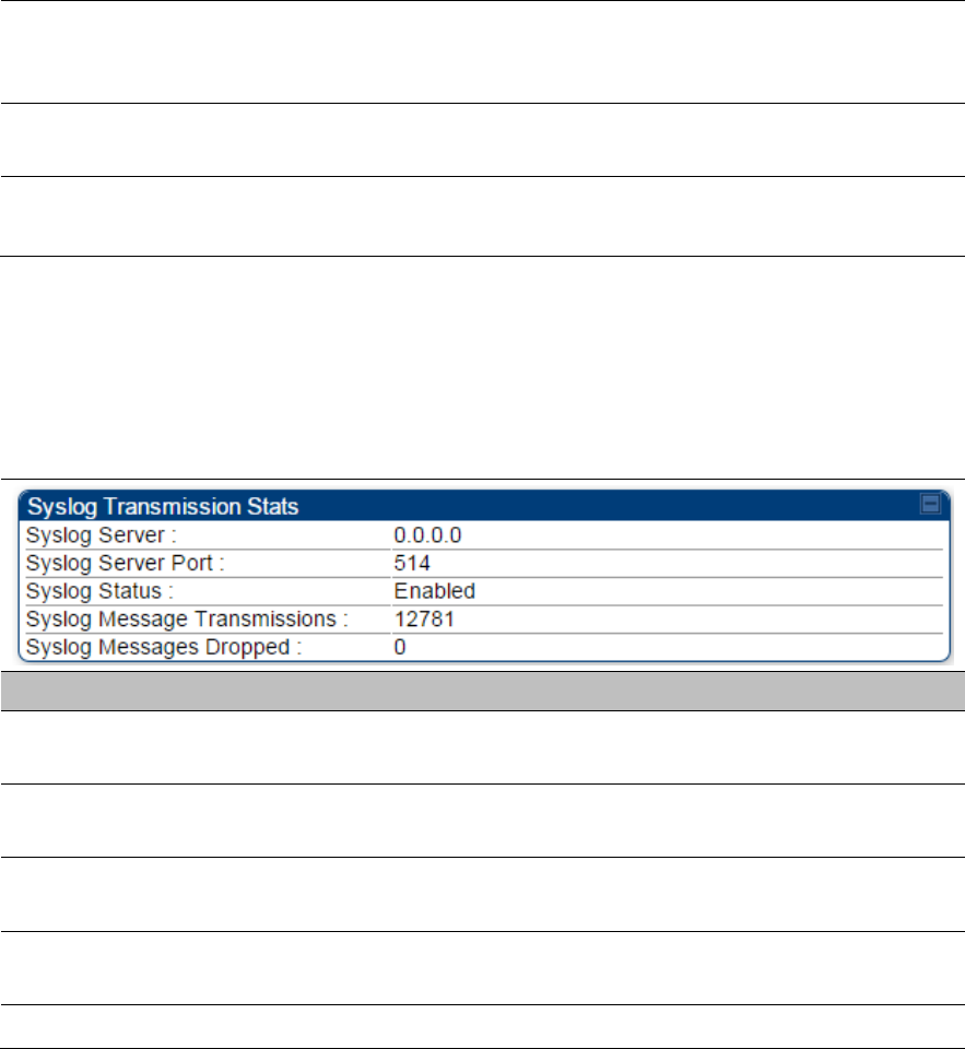
Interpreting syslog statistics
The Statistics > Syslog Statistics page displays statistics of syslog messages. The page is applicable
for all modules (AP/SM/BHM/BHS). The Syslog Statistics page is explained in Table 241.
Table 241 Syslog statistics page attributes – AP/SM/BH
Attribute Meaning
Syslog Server This displays dotted decimal or DNS name (if the DNS is enabled) of
the syslog server address.
Syslog Server Port The syslog server port (default 514) to which syslog messaging is
sent.
Syslog Status This indicates status of syslog messaging. It can be Enable or
Disabled based on configuration
Syslog Message
Transmissions This field indicates the count of syslog messages sent to UDP layer.
Syslog Message Dropped This field indicates the count of dropped syslog messages.
Interpreting Frame Utilization statistics
The Frame Utilization Statistics is a feature helps user to understand how effectively the RF channel is
being utilized. This feature allows to check Time Division Duplex (TDD) frame utilization pattern and
diagnose for any excessive usage in uplink or downlink direction.
This forms the first step of identifying the TDD frame utilization information. If the user finds excessive
utilization based on this stats, the second step would be to take several actions like sectorization, tuning
the uplink/downlink ratio etc. to improve RF channel utilization. Efficient use of the TDD frame will help to
achieve optimum performance of link.
Chapter 9: Operation System statistics
Page 9-26
Note
The backhauls (BHM and BHS) will have only the downlink scheduler based statistics
Table 242 Frame utilization statistics for PMP 450m AP
Chapter 9: Operation System statistics
Page 9-27
Chapter 9: Operation System statistics
Page 9-28
Attribute Meaning
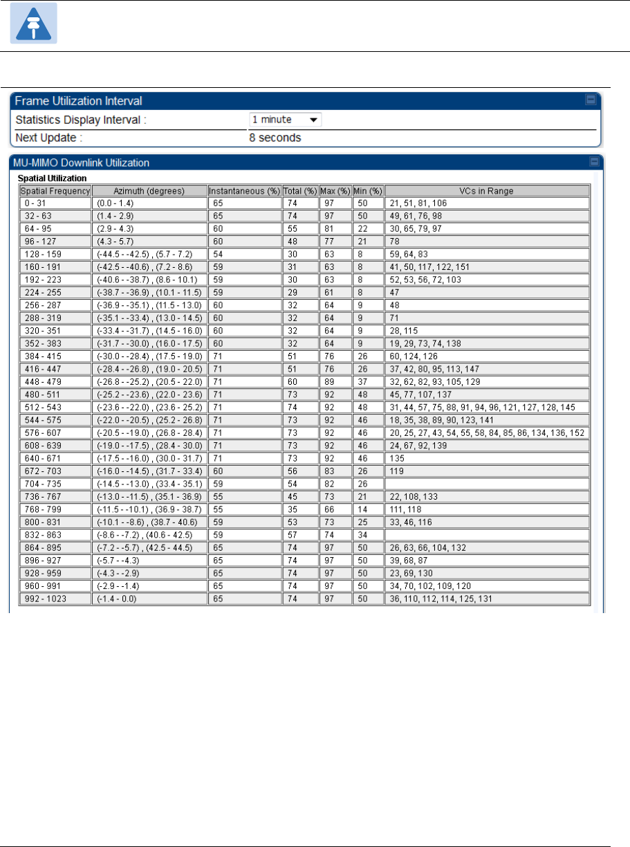
Frame Utilization Interval
Statistics Display interval This allows to configure timer interval to monitor and display the
frame utilization statistics. It can be configured for 1 minute (low
interval), 5 minutes (medium interval) or 15 minutes (high interval)
based on requirement.
MU-MIMO Utilization
Spatial Utilization This is a table (32 rows) that lists frame utilization for each spatial
frequency (SF) range with following information:
Spatial frequency: Range of spatial frequency for each bin.
Each bin includes 32 consecutive spatial frequency values.
Azimuth (degrees): Azimuth range in degrees corresponding to
the spatial frequencies of the bin. The zero degree azimuth is
boresight.
Note:
Some SF ranges correspond to multiple azimuth ranges.
This is due to the fact that for some spatial frequencies
the AP generates beams in multiple azimuth directions.
The SM can be physically located in any of the azimuth
ranges.
Spatial Utilization Instantaneous (%): Frame utilization for the SF bin, updated
every 500 ms. The frame utilization percentage accounts for all
traffic, both sector mode and MU-MIMO transmissions.
Total (%): Average utilization in the SF bin for the past 1/5/15
minutes, as selected in the Statistics Display Interval.
Max (%): Maximum Instantaneous utilization in the 1/5/15 minute
interval
Min (%): Minimum Instantaneous utilization in the 1/5/15 minute
interval
VCs in Range: List of VCs with spatial frequency falling in the
bin.
Note:
The size of each SF bin is smaller than the beam
generated by the AP during a MU-MIMO transmission.
This means that when a VC in a bin is scheduled for a
MU-MIMO transmission, the adjacent bins also receive
the signal, and the transmission is counted towards their
utilization as well. Bins with consistent low utilization
indicate the areas of the sector where more SMs could
be installed, or the customers that could be offered
higher data plans.

Chapter 9: Operation System statistics
Page 9-29
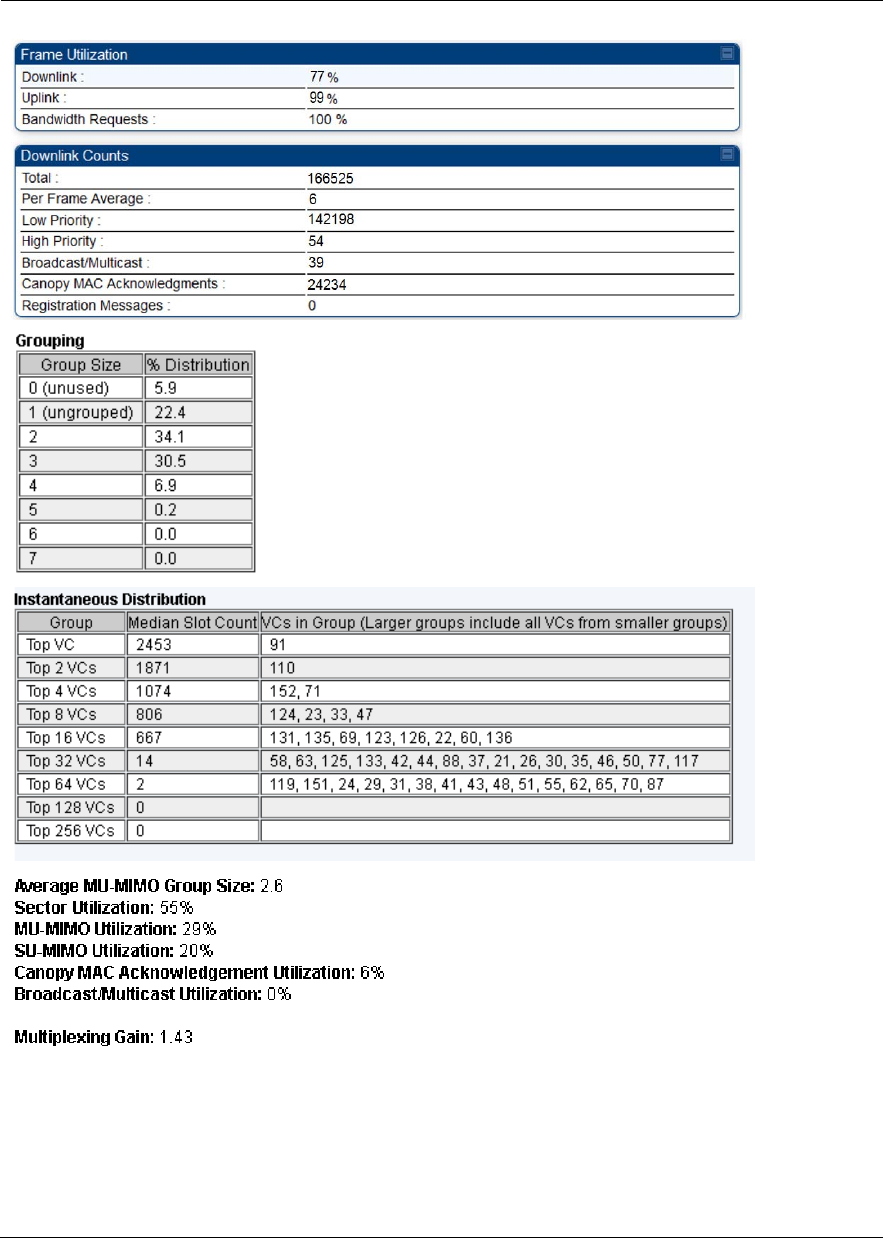
Grouping This specifies the distribution of group size for the past 1/5/15
minutes. For each group size, from 0 to 7, the table shows the
percentage of slots using that group size.
A group size of 0 corresponds to unused slots.
A group size of 1 corresponds to sector mode transmissions
(ungrouped).
A group size of 2 to 7 corresponds to MU-MIMO transmissions.
Instantaneous Distribution This table is updated every 500 ms and displays the following:
Group: Each row corresponds to the top (most active) 1, 2, 4, 8,
16, 32, 64, 128, and 256 VCs.
Median Slot Count: Median value of the average number of slots
scheduled for the VCs in each group in the past 500 ms.
VCs in Group: List of VCs belonging to each bin where each bin
includes all VCs listed in preceding rows along with the VCs
listed in the corresponding row.
For example, the row labeled “Top 32 VCs” considers up to 32
VCs, which are: one VC listed in “Top VC” row, plus one VC
listed in “Top 2 VCs” row, plus 2 VCs listed in “Top 4 VCs” row,
plus four VCs listed in “Top 8 VCs” row, plus 8 VCs listed in “Top
16 VCs” rows, plus up to 16 VCs listed in “Top 32 VCs” row. If
the number of VCs in the sector is less than 32, this row will
include less than 16 VCs; if the number of VCs in the sector is
equal to or greater than 32, this row will include 16 VCs.
Note:
For best MU-MIMO operation, the distribution of the
median values in this table should be as close to flat as
possible. If many VCs are equally active, there is a
higher probability of being able to group their
transmissions. If only a few VCs are active, the
probability of grouping transmissions is lower, and both
the Average MU-MIMO Group size and the Multiplexing
Gain are expected to be lower.
Average MU-MIMO Group
Size
This specifes the average number of users in the MU-MIMO groups
formed in the last 1/5/15 minutes.
Sector Utilization This specifes the average of the 32 values of the Spatial Utilization
table.
MU-MIMO Utilization This specifies the portion of the Sector Utilization used for MU-MIMO
transmissions.
SU-MIMO Utilization This specifies the portion of the Sector Utilization used for SU-MIMO
transmissions.

Chapter 9: Operation System statistics
Page 9-30
Canopy MAC
Acknowledgment Utilization
This specifies the portion of the Sector Utilization used for
acknowledgments transmission.
Broadcast/Multicast
Utilization
This specifies the portion of the Sector Utilization used for broadcast
and multicast transmissions.
Multiplexing Gain This specifies the ratio between the number of logical slots and the
number of physical slots used.
A physical slot is an OFDM symbol. In non MU-MIMO mode, each
logical slot is sent during one physical slot. In MU-MIMO mode a
number of logical slots are sent during a physical slot, equal to the
number of VCs in the group. A logical slot carries new information; if
data is repeated in a group, because some VCs have more data to
send then others, then the repeated transmissions are not counted as
a logical slots.
Without MU-MIMO operation, the multiplexing gain would always be
equal to 1.
With MU-MIMO operation, this number accounts for parallel
transmissions to multiple users in the MU-MIMO group.
The difference between the Average MU-MIMO Group Size and the
Multiplexing Gain is that the Average MU-MIMO Group Size only
considers the MU-MIMO groups, and it averages the number of VCs
in the Group. The Multiplexing Gain also considers non MU-MIMO
transmissions, which are counted as groups of size 1.
Frame Utilization
Downlink This indicates the percentage of downlink data slots used against the
maximum number of slots possible in the configured interval.
Uplink This indicates the percentage of uplink data slots used against the
maximum number of uplink slots possible in the configured interval.
Bandwidth Requests The "Bandwidth Request" is a message sent from the SM to the AP
asking to be scheduled for bandwidth to send in the uplink. This gets
transmitted in the unscheduled portion of the uplink. Unscheduled
uplink is defined as Contention Slots + unscheduled uplink slots.
Since this is sent in the unscheduled portion of the uplink, it will result
in collisions when SMs randomly pick the same slot.
The "Bandwidth Request Missed" metrics are to add data to know
how many of requests are colliding. If it is near 100%, then near all of
the SM’s bandwidth requests are getting through to the AP, so this a
is near perfect scenario. If it is significantly less than that, you may be
experiencing uplink latency as your SMs are attempting to request
bandwidth and are unable to do so.
Also note that if it is consistently at 100% the AP may be able to
reduce its contention slots to a lower value and gain more data slots.

Chapter 9: Operation System statistics
Page 9-31
Downlink Counts
Total This indicates the sum of all downlink data slots used in the
configured interval.
Per Frame Average This indicates the average data per frame in the downlink traffic.
Low Priority The number of downlink data slots used for low priority downlink
traffic.
High Priority The number of downlink data slots used for high priority downlink
traffic.
Broadcast/Multicast The number of downlink data slots used for broadcast and multicast
traffic.
Canopy MAC
Acknowledgements
The number of downlink data slots used as ACKs.
Registration Messages The number of downlink data slots used for registration messages.
Uplink Counts
Total This indicates the sum of all uplink data slots used in configured
interval.
Per Frame Average This indicates the average data per frame in the uplink traffic.
Low Priority The number of uplink data slots used for low priority uplink traffic.
High Priority The number of uplink data slots used for high priority uplink traffic.
Canopy MAC
Acknowledgements
The number of uplink data slots used as ACKs.
Contention Slots The number of (reserved contention slots + unscheduled symbols
that can be used as contention slots) Contention slots configured by
the operator.
Contention Slots Average
Per Frame
It is the average number of contention slots in a frame for the last
duration. Duration is 1/5/15 mins.
Bandwidth Requests
Received
This indicates the number of Bandwidth Requests received from
SMs.
Bandwidth Requests
Missed
This indicates how many of Bandwidth Requests are colliding.
Maximum possible counts
Downlink This indicates the maximum possible downlink data slots in the
configured interval. This is based on the configuration of Channel
Bandwidth, Frame period, uplink/downlink allocation, contention slots
and configured Statistics Display interval.

Chapter 9: Operation System statistics
Page 9-32
Uplink This indicates the maximum possible uplink data slots in the
configured interval. This is based on the configuration of Channel
Bandwidth, Frame period, uplink/downlink allocation, contention slots
and configured Statistics Display interval.
Contention This indicates the maximum possible contention slots.
Packet Discard counts
Ethernet indiscards This indicates the number of Ethernet packets discarded in the IN
queue.
Ethernet outdiscards This indicates the number of Ethernet packets discarded in the OUT
queue.
Radio indiscards This indicates the number of packets discarded over radio in the IN
queue.
Radio outdiscards This indicates the number of packets discarded over radio in the OUT
queue.
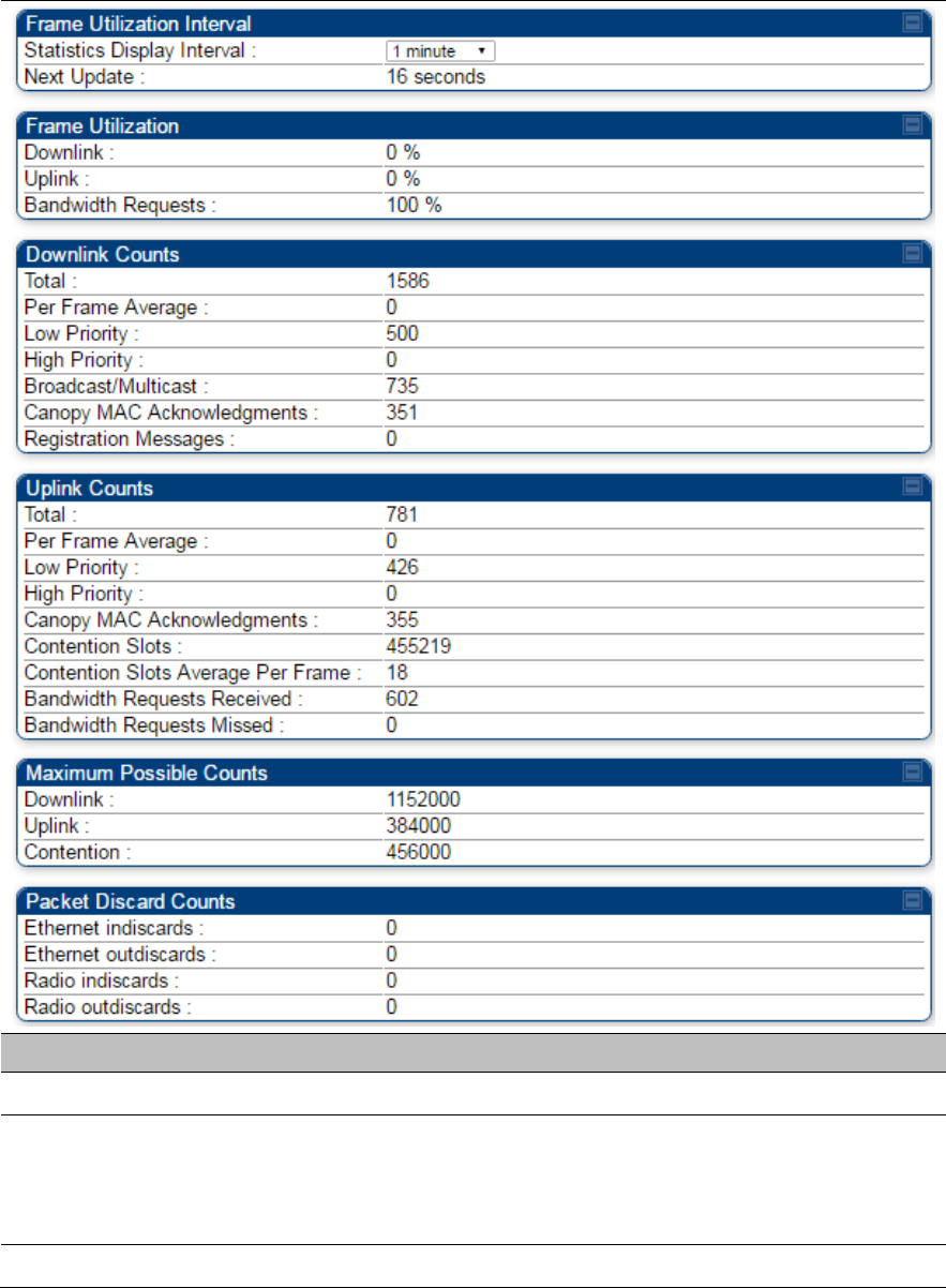
Chapter 9: Operation System statistics
Page 9-33
Table 243 Frame utilization statistics for 450/450i/450m
Attribute Meaning
Frame Utilization Interval
Statistics Display interval This allows to configure timer interval to monitor and display the
frame utilization statistics. It can be configured for 1 minute (low
interval), 5 minutes (medium interval) or 15 minutes (high interval)
based on requirement.
Frame Utilization

Chapter 9: Operation System statistics
Page 9-34
Downlink This indicates the percentage of downlink data slots used against the
maximum number of slots possible in the configured interval.
Uplink This indicates the percentage of uplink data slots used against the
maximum number of uplink slots possible in the configured interval.
Bandwidth Requests The "Bandwidth Request" is a message sent from the SM to the AP
asking to be scheduled for bandwidth to send in the uplink. This gets
transmitted in the unscheduled portion of the uplink. Unscheduled
uplink is defined as Contention Slots + unscheduled uplink slots.
Since this is sent in the unscheduled portion of the uplink, it will result
in collisions when SMs randomly pick the same slot.
The "Bandwidth Request Missed" metrics are to add data to know
how many of requests are colliding. If it is near 100%, then near all of
the SM’s bandwidth requests are getting through to the AP, so this a
is near perfect scenario. If it is significantly less than that, you may be
experiencing uplink latency as your SMs are attempting to request
bandwidth and are unable to do so.
Also note that if it is consistently at 100% the AP may be able to
reduce its contention slots to a lower value and gain more data slots.
Downlink Counts
Total This indicates the sum of all downlink data slots used in the
configured interval.
Per Frame Average This indicates the average data per frame in the downlink traffic.
Low Priority The number of downlink data slots used for low priority downlink
traffic.
High Priority The number of downlink data slots used for high priority downlink
traffic.
Broadcast/Multicast The number of downlink data slots used for broadcast and multicast
traffic.
Canopy MAC
Acknowledgements
The number of downlink data slots used as ACKs.
Registration Messages The number of downlink data slots used for registration messages.
Uplink Counts
Total This indicates the sum of all uplink data slots used in configured
interval.
Per Frame Average This indicates the average data per frame in the uplink traffic.
Low Priority The number of uplink data slots used for low priority uplink traffic.
High Priority The number of uplink data slots used for high priority uplink traffic.

Chapter 9: Operation System statistics
Page 9-35
Canopy MAC
Acknowledgements
The number of uplink data slots used as ACKs.
Contention Slots The number of (reserved contention slots + unscheduled symbols
that can be used as contention slots) Contention slots configured by
the operator.
Contention Slots Average
Per Frame
It is the average number of contention slots in a frame for the last
duration. Duration is 1/5/15 mins.
Bandwidth Requests
Received
This indicates the number of Bandwidth Requests received from
SMs.
Bandwidth Requests
Missed
This indicates how many of Bandwidth Requests are colliding.
Maximum possible counts
Downlink This indicates the maximum possible downlink data slots in the
configured interval. This is based on the configuration of Channel
Bandwidth, Frame period, uplink/downlink allocation, contention slots
and configured Statistics Display interval.
Uplink This indicates the maximum possible uplink data slots in the
configured interval. This is based on the configuration of Channel
Bandwidth, Frame period, uplink/downlink allocation, contention slots
and configured Statistics Display interval.
Contention This indicates the maximum possible contention slots.
Packet Discard counts
Ethernet indiscards This indicates the number of Ethernet packets discarded in the IN
queue.
Ethernet outdiscards This indicates the number of Ethernet packets discarded in the OUT
queue.
Radio indiscards This indicates the number of packets discarded over radio in the IN
queue.
Radio outdiscards This indicates the number of packets discarded over radio in the OUT
queue.

Chapter 9: Operation Radio Recovery
Page 9-36
Radio Recovery
This section describes:
How to recover a PMP/PTP 450i and PMP 450m Series ODUs from configuration errors or software
image corruption
How to override a PMP/PTP 450 Series ODUs from forgotten IP address and password to factory
default
Radio Recovery Console– PMP/PTP 450i/450b and
PMP 450m
Recovery mode allows to restore IP address and password. Also, it allows new main application software
to be loaded even when the integrity of the existing main application software image has been
compromised. The most likely cause of an integrity problem with the installed main application software is
where the power supply has been interrupted during a software upgrade.
Note
When Recovery has been entered through a power on/off/on cycle, the ODU will revert to
normal operation if no web access has been made to the unit within 30 seconds. This
prevents the unit remaining inadvertently in recovery following a power outage.
Options in recovery mode are:
Boot with normal operation
Boot with default Canopy system software settings
Load a previous SW image
The last most recent software images loaded to the board are retained. However the factory image is not
retained.
Boot with default Canopy system software settings (similar to the hardware Default Plug based on 450
Platforms Family).
Note
The unit may enter recovery console automatically, in response to some failures.
Note
Once the unit has entered recovery, it will switch back to normal operation if no access has
been made to the recovery web page within 30 seconds.
Use below procedure to enter in recovery console manually.
Chapter 9: Operation Radio Recovery
Page 9-37
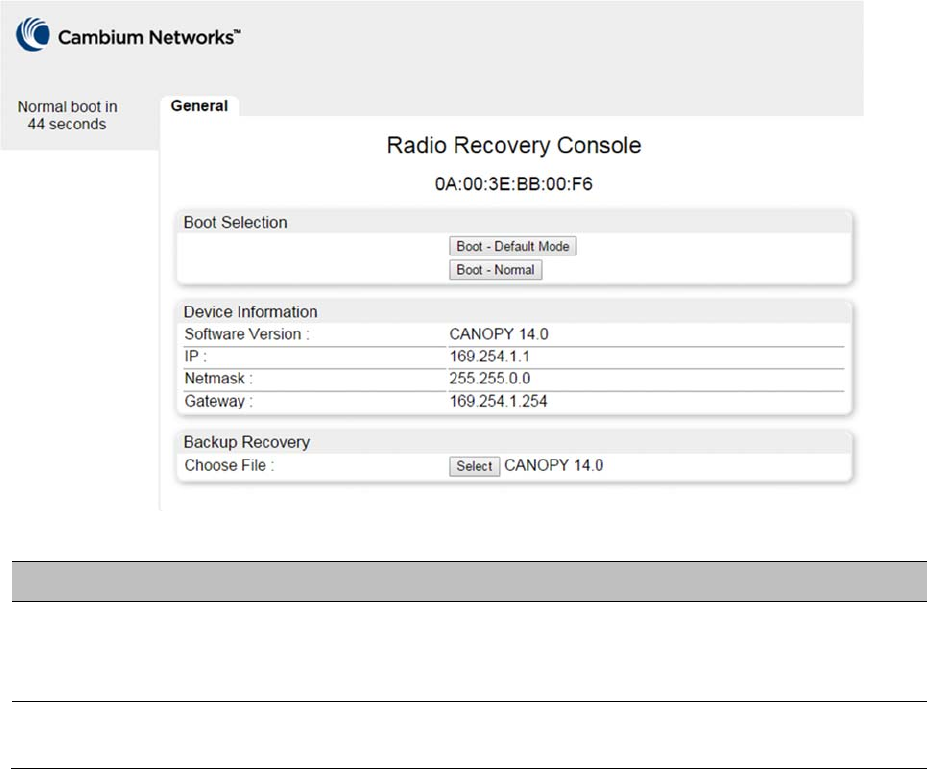
Chapter 9: Operation Radio Recovery
Page 9-38
Procedure 35 Radio Recovery Console
1 Apply power to PSU for at least 10 seconds.
2 Remove power from the PSU, and then re-apply it as soon as the power indicator light goes
out (about 1 - 2 seconds).
3 When the unit is in recovery mode, access the web interface by entering the default IP
address 169.254.1.1. The Recovery Image Warning page is displayed.
4 Review the Boot Selection (Table 244).
5 Select a recovery option
Figure 201 Recovery Options page
Table 244 Recovery Options attributes
Attribute Meaning
Boot Selection Boot – Default Mode: Use this option to temporarily set the IP and Ethernet
attributes to factory defaults until the next reboot.
Boot – Normal: Use this option to reboot the unit.
IP address, Netmask,
Gateway
These fields display IP address, Netmask and Gateway of the radio while it is
in recovery or default mode.

Chapter 9: Operation Radio Recovery
Page 9-39
Note
The radio enters recovery mode when a short power cycle is used. The radio will boot
normally if power has been removed for a longer period (typically 5 - 10 seconds).
Default Mode (or Default/Override Plug) - PMP/PTP 450
Series
The default modeallows to temporarily override some PMP/PTP 450 Series ODU settings and thereby
regain control of the module by powering the module on with the Default Plug inserted into the unit’s
synchronization (RJ11) port.
This override plug is needed for access to the module in any of the following cases:
You have forgotten either
o the IP address assigned to the ODU.
o the password that provides access to the ODU.
The ODU has been locked by the No Remote Access feature.
You want local access to a module that has had the 802.3 link disabled in the Configuration page.
You can configure the module such that, when it senses the override plug, it responds by either
resetting the LAN1 IP address to 169.254.1.1, allowing access through the default configuration
without changing the configuration, whereupon you will be able to view and reset any non-default
values as you wish.
resetting all configurable parameters to their factory default values.
Note
The Default Plug is available from Best-Tronics Manufacturing, Inc.
See http://www.best-tronics.com/cambium.htm as Part BT-0583 (RJ-11 Default Plug).
Alternatively, you can fabricate an override plug. See Override plug cable on page 5-15 for
pinout.

Chapter 9: Operation Radio Recovery
Page 9-40
Using the Default/Override Plug
The following section details usage of the override plug to regain access to PMP/PTP 450 Series ODU.
Note
While the override plug is connected to a PMP/PTP 450 Series ODU, the ODU can neither
register nor allow registration of another ODU.
Note
Since the 900 MHz SM is based on the 450 Series, it only supports the "Default Plug" mode
of overriding.
Use below procedure to enter in default mode manually.
Procedure 36 Default mode
1 Insert the override plug into the RJ-11 GPS utility port of the module.
2 Power cycle by removing, then re-inserting, the Ethernet cable.
RESULT: The module boots with the default IP address of 169.254.1.1, password fields
blank, and all other configuration values as previously set.
3 Wait approximately 30 seconds for the boot to complete.
4 Remove the override plug.
5 Set passwords and IP address as desired.
6 Change configuration values if desired.
7 Click the Save Changes button.
8 Click the Reboot button.

Page 10-1
Chapter 10: Reference information
This chapter contains reference information and regulatory notices that apply to the 450 Platform Family
ODUs.
The following topics are described in this chapter:
Equipment specifications on page 10-2 contains specifications of the 450 Platform Family, ODU
specifications including RF bands, channel width and link loss.
Data network specifications on page 10-43 shows the 450 Platform Family Ethernet interface
specifications.
Compliance with safety standards on page 4-22 lists the safety specifications against which 450
Platform Family ODU has been tested and certified. It also describes how to keep RF exposure within
safe limits.
Country specific radio regulations on page 10-46 describes how the 450 Platform Family complies
with the radio regulations that are enforced in various countries.
Equipment Disposal on page 10-49 describes the Equipment Disposal system for Electronic and
Electric Equipment.

Chapter 10: Reference information Equipment specifications
Page 10-2
Equipment specifications
This section contains specifications of the AP, SM, BHM and BHS associated supplies required for 450
Platform Family installations.
Specifications for PMP 450m Series - AP
The PMP 450m AP conforms to the specifications listed in Table 245.
Table 245 PMP 450m Series - AP specifications
Category Specification
Model Number PMP 450m AP
Spectrum
Channel Spacing Configurable on 2.5 MHz increments
Frequency Range 5150 to 5925 MHz
Channel Bandwidth 5, 10, 15, 20, and 40 MHz
Interface
MAC (Media Access
Control) Layer
Cambium Proprietary
Physical Layer 14x14 Multi-User MIMO OFDM
Ethernet Interface 100/1000BaseT, half/full duplex, rate auto negotiated
(802.3 compliant)
Protocols Used IPv4, UDP, TCP, IP, ICMP, Telnet, SNMP, HTTP, FTP
Network Management HTTP, HTTPS, Telnet, FTP, SNMP v3
VLAN 802.1ad (DVLAN Q-in-Q), 802.1Q with 802.1p priority,
dynamic port VID
Sensitivity
Nominal Receive
Sensitivity (w/ FEC) @ 5
MHz Channel
5.1 GHz 1x=-101.6 dBm, 2x=-96.2 dBm, 4x=-90.2 dBm, 6x=-84
dBm, 8x=-76.6 dBm
5.2 GHz 1x=-101.3 dBm, 2x=-96.3 dBm, 4x=-89.7 dBm, 6x=-83.3
dBm, 8x=-75.7 dBm
5.4 GHz 1x=-101.1 dBm, 2x=-96.8 dBm, 4x=-90 dBm, 6x=-83.9
dBm, 8x=-76.2 dBm

Chapter 10: Reference information Equipment specifications
Page 10-3
5.8 GHz 1x=-101.6 dBm, 2x=-96.6 dBm, 4x=-89.9 dBm, 6x=-83.7
dBm, 8x=-76.3 dBm
Nominal Receive
Sensitivity (w/ FEC) @
10 MHz Channel
5.1 GHz 1x=-99 dBm, 2x=-94.6 dBm, 4x=-87.8 dBm, 6x=-81.6 dBm,
8x=-74.6 dBm
5.2 GHz 1x=-98.8 dBm, 2x=-93.8 dBm, 4x=-87.6 dBm, 6x=-81.4
dBm, 8x=-73.6 dBm
5.4 GHz 1x=-98.1 dBm, 2x=-94.1 dBm, 4x=-87.5 dBm, 6x=-81.5
dBm, 8x=-73.8 dBm
5.8 GHz 1x=-98.5 dBm, 2x=-93.6 dBm, 4x=-87.5 dBm, 6x=-81.2
dBm, 8x=-73.7 dBm
Nominal Receive
Sensitivity (w/ FEC) @
15 MHz Channel
5.1 GHz 1x=-97.3 dBm, 2x=-92.5 dBm, 4x=-86.3 dBm, 6x=-79.9
dBm, 8x=-72.9 dBm
5.2 GHz 1x=-96.7 dBm, 2x=-91.9 dBm, 4x=-85.7 dBm, 6x=-79.5
dBm, 8x=-72.5 dBm
5.4 GHz 1x=-96.2 dBm, 2x=-92.1 dBm, 4x=-85.5 dBm, 6x=-79.4
dBm, 8x=-72.4 dBm
5.8 GHz 1x=-97.2 dBm, 2x=-92.4 dBm, 4x=-85.5 dBm, 6x=-79.4
dBm, 8x=-72.5 dBm
Nominal Receive
Sensitivity (w/ FEC) @
20 MHz Channel
5.1 GHz 1x=-96.3 dBm, 2x=-91.9 dBm, 4x=-85.3 dBm, 6x=-79.3
dBm, 8x=-71.3 dBm
5.2 GHz 1x=-95.8 dBm, 2x=-91.8 dBm, 4x=-84.8 dBm, 6x=-78.8
dBm, 8x=-71.8 dBm
5.4 GHz 1x=-95.1 dBm, 2x=-91.4 dBm, 4x=-84.8 dBm, 6x=-78.3
dBm, 8x=-71.1 dBm
5.8 GHz 1x=-95.8 dBm, 2x=-91.3 dBm, 4x=-84.7 dBm, 6x=-78.3
dBm, 8x=-70.8 dBm
Performance
Subscriber Per Sector Up to 238
ARQ Yes
Cyclic Prefix 1/16
Frame Period 2.5 ms

Chapter 10: Reference information Equipment specifications
Page 10-4
Modulation Levels (Adaptive) Modulation
Levels
MCS SNR (in dB)
2x QPSK 10
4x 16QAM 17
6x 64QAM 24
8x 256QAM 32
Latency 10 ms, typical (MU-MIMO introduces additional latency
only for the low priority traffic)
Maximum Deployment Range Up to 40 miles (64 km)
GPS Synchronization Yes, via Autosync (UGPS)
Quality of Service Diffserv QoS
Link Budget
Antenna Beam Width 5 GHz 90° integrated sector (Dual polarity, H+V)
Antenna Gain +14 dBi
Maximum Transmit
Power
+24 dBm combined
Physical
Data, Sync/AUX and
SFP port
RJ45 1000BASE-T Ethernet Data
AUX port for UGPS or PoE out to 802.3at
Antenna Connection Integrated Sector Array
Surge Suppression (with
LPU)
EN61000-4-5: 1.2 us/50 us, 500 V voltage waveform
Recommended external surge suppressor:
Cambium Networks Model # C000065L007A
Mean Time Between
Failure
> 40 Years
Environmental IP66, IP67
Temperature / Humidity -40°C to +60°C (-40°F to +140°F)
0-95% non-condensing
Weight Integrated Approx. 14.2 kg (31 bs)
@90 mph / 144 kph 460 N

Chapter 10: Reference information Equipment specifications
Page 10-5
Wind Loading – Front
Facing
@110 mph /177 kph 700 N
Dimension (HxWxD) Integrated 52 x 65 x 11 cm (20.3” x 25.7” x 4.4”)
Power Consumption 70 W typical, 80 W peak
(up to 110 W max with AUX port PoE enabled)
Input Voltage 58 V, 1.7 A
Mounting Pole mount with included brackets
Security
Encryption 56-bit DES, FIPS-197 128-bit AES

Chapter 10: Reference information Equipment specifications
Page 10-6
Specifications for PMP 450i Series - AP
The PMP 450i AP conforms to the specifications listed in Table 246.
Table 246 PMP 450i Series - AP specifications
Category Specification
Model Number PMP 450i AP
Spectrum
Channel Spacing 5, 7, 10, 15, 20, 30, and 40 MHz Channel Bandwidth
Configurable on 2.5 MHz increments
Frequency Range 902 to 928 MHz
3300 - 3900 MHz
4900 - 5925 MHz
Channel Bandwidth 902 – 928
MHz
5, 7, 10, 15, and 20 MHz
3300 - 3900
MHz
5, 7, 10, 15, 20, 30, and 40 MHz
4900 – 5925
MHz
5, 10, 15, 20, 30, and 40 MHz
Interface
MAC (Media Access
Control) Layer
Cambium Proprietary
Physical Layer 2x2 MIMO OFDM
Ethernet Interface 10/100/1000BaseT, half/full duplex, rate auto negotiated
(802.3 compliant)
Protocols Used IPv4, UDP, TCP, IP, ICMP, Telnet, SNMP, HTTP, FTP
Network Management HTTP, HTTPS, Telnet, FTP, SNMP v3
VLAN 802.1ad (DVLAN Q-in-Q), 802.1Q with 802.1p priority,
dynamic port VID
Sensitivity
Nominal Receive
Sensitivity (w/ FEC) @ 5
MHz Channel
900 MHz 1x = -91.9 dBm, 2x = -86.7 dBm, 4x = -80.9 dBm, 6x = -75
dBm, 8x = -68.8 dBm
3.5 GHz 1x = -92.7 dBm, 2x = -88.7 dBm, 4x = -82.7 dBm, 6x = -
75.8 dBm, 8x = -69 dBm

Chapter 10: Reference information Equipment specifications
Page 10-7
3.6 GHz 1x=-91 dBm, 2x=-86.1 dBm, 4x=-80.2 dBm, 6x=-73.1 dBm,
8x=-66 dBm
4.9 GHz 1x = -91.6 dBm, 2x = -87.6 dBm, 4x = -80.4 dBm, 6x = -
73.2 dBm, 8x = -66 dBm
5.4 GHz 1x = -92 dBm, 2x = -87 dBm, 4x = -80.8 dBm, 6x = -73.7
dBm, 8x = -66.6 dBm
5.8 GHz 1x = -91.5 dBm, 2x = -87 dBm, 4x = -80.2 dBm, 6x = -73.1
dBm, 8x = -66 dBm
Nominal Receive
Sensitivity (w/ FEC) @ 7
MHz Channel
900 MHz 1x = -90 dBm, 2x = -85.9 dBm, 4x = -79.8 dBm, 6x = -73.6
dBm, 8x = -67.9 dBm
3.5 GHz 1x=-91.8 dBm, 2x=-87.7 dBm, 4x=-80.8 dBm, 6x=-74.7
dBm, 8x=-67.3 dBm
3.6 GHz 1x=-90 dBm, 2x=-87 dBm, 4x=-79.8 dBm, 6x=-73.8 dBm,
8x=-67.2 dBm
Nominal Receive
Sensitivity (w/ FEC) @
10 MHz Channel
900 MHz 1x = -90.6 dBm, 2x = -85.2 dBm, 4x = -79.1 dBm, 6x = -
73.2 dBm, 8x = -66.2 dBm
3.5 GHz 1x=-90.2 dBm, 2x=-86.2 dBm, 4x=-80 dBm, 6x=-73.1 dBm,
8x=-66.7 dBm
3.6 GHz 1x=-89.5 dBm, 2x=-85.7 dBm, 4x=-79.8 dBm, 6x=-72.8
dBm, 8x=-66.3 dBm
4.9 GHz 1x = -89.1 dBm, 2x = -85 dBm, 4x = -77.9 dBm, 6x = -71.8
dBm, 8x = -64.6 dBm
5.4 GHz 1x = -89.5 dBm, 2x = -85.4 dBm, 4x = -78.2 dBm, 6x = -
72.2 dBm, 8x = -64.8 dBm
5.8 GHz 1x = -89.5 dBm, 2x = -84.7 dBm, 4x = -77.8 dBm, 6x = -
71.6 dBm, 8x = -64 dBm
Nominal Receive
Sensitivity (w/ FEC) @
15 MHz Channel
900 MHz 1x=-88.2 dBm, 2x=-83.2 dBm, 4x=-76.3 dBm, 6x=-70.2
dBm, 8x=-64.3 dBm
3.5 GHz 1x=-89 dBm, 2x=-84 dBm, 4x=-77.9 dBm, 6x=-72 dBm,
8x=-64.8 dBm
3.6 GHz 1x=-87.6 dBm, 2x=-83.7 dBm, 4x=-77.5 dBm, 6x=-71.6
dBm, 8x=-64.5 dBm

Chapter 10: Reference information Equipment specifications
Page 10-8
4.9 GHz 1x = -87.2 dBm, 2x = -83 dBm, 4x = -75.8 dBm, 6x = -69.6
dBm, 8x = -62.6 dBm
5.4 GHz 1x = -87.2 dBm, 2x = -83.3 dBm, 4x = -76.2 dBm, 6x = -
70.1 dBm, 8x = -63 dBm
5.8 GHz 1x = -87.7 dBm, 2x = -82.7 dBm, 4x = -75.5 dBm, 6x = -
69.6 dBm, 8x = -62.4 dBm
Nominal Receive
Sensitivity (w/ FEC) @
20 MHz Channel
900 MHz 1x = -86.99 dBm, 2x = -82 dBm, 4x = -75.9 dBm, 6x = -
69.9 dBm, 8x = -62.9 dBm
3.5 GHz 1x=-87.4 dBm, 2x=-83 dBm, 4x=-76.9 dBm, 6x=-69.9 dBm,
8x=-63 dBm
3.6 GHz 1x=-86.4 dBm, 2x=-82.5 dBm, 4x=-76.4 dBm, 6x=-69.4
dBm, 8x=-62.9 dBm
4.9 GHz 1x = -86.1 dBm, 2x = -82.1 dBm, 4x = -74.8 dBm, 6x = -
68.8 dBm, 8x = -61.7 dBm
5.4 GHz 1x = -86.6 dBm, 2x = -81.3 dBm, 4x = -75.5 dBm, 6x = -
68.6 dBm, 8x = -62 dBm
5.8 GHz 1x = -85.8 dBm, 2x = -80.7 dBm, 4x = -74.6 dBm, 6x = -
68.7 dBm, 8x = -61 dBm
Nominal Receive
Sensitivity (w/ FEC) @
30 MHz Channel
3.5 GHz 1x=-85.6 dBm, 2x=-81.7 dBm, 4x=-74.5 dBm, 6x=-68 dBm,
8x=-61.5 dBm
3.6 GHz 1x=-85.5 dBm, 2x=-80.5 dBm, 4x=-74.4 dBm, 6x=-68.4
dBm, 8x=-61.5 dBm
4.9 GHz 1x = -84.1 dBm, 2x = -80 dBm, 4x = -73 dBm, 6x = -66.4
dBm, 8x = -59.6 dBm
5.4 GHz 1x = -84.5 dBm, 2x = -82 dBm, 4x = -75 3.5Bm, 6x = -67.4
dBm, 8x = -60.2 dBm
5.8 GHz 1x = -84.1 dBm, 2x = -80 dBm, 4x = -73 dBm, 6x = -66.5
dBm, 8x = -59.4 dBm
3.5 GHz 1x=-83.9 dBm, 2x=-79.5 dBm, 4x=-73 dBm, 6x=-66 dBm,
8x=-58.5 dBm

Chapter 10: Reference information Equipment specifications
Page 10-9
Nominal Receive
Sensitivity (w/ FEC) @
40 MHz Channel
3.6 GHz 1x=-82.8 dBm, 2x=-79 dBm, 4x=-73 dBm, 6x=-66 dBm,
8x=-59 dBm
4.9 GHz 1x=-83.9 dBm, 2x=-78.9 dBm, 4x=-72 dBm, 6x=-66 dBm,
8x=-56.6 dBm
5.4 GHz 1x=-83.7 dBm, 2x=-78.5 dBm, 4x=-72.4 dBm, 6x=-66 dBm,
8x=-58 dBm
5.8 GHz 1x=-83.8 dBm, 2x=-78.4 dBm, 4x=-72 dBm, 6x=-66 dBm,
8x=-57 dBm
Performance
ARQ Yes
Cyclic Prefix 1/16
Frame Period 2.5 ms or 5.0 ms
Modulation Levels
(Adaptive)
Modulation
Levels
MCS SNR (in dB)
2x QPSK 10
4x 16QAM 17
6x 64QAM 24
8x 256QAM 32
Latency 3 - 5 ms
Maximum Deployment
Range
Up to 40 miles (64 km)
Up to 120 miles (190 km) for 900 MHz
GPS Synchronization Yes, via Autosync (CMM4), via UGPS
Quality of Service Diffserv QoS
Link Budget
Antenna Beam Width 900 MHz 65° sector antenna (Dual Slant)
3 GHz 90° sector for integrated (Dual polarity, slant +45° and -
45°)
5 GHz 90° (3 dB roll off) sector for integrated (Dual polarity, H+V)

Chapter 10: Reference information Equipment specifications
Page 10-10
Antenna Gain (Does not
include cable loss,
~1dB)
900 MHz 13 dBi
3 GHz 17 dBi integrated 90° sector or external
5 GHz 17 dBi integrated 90° sector or external
Transmit Power Range 40 dB dynamic range (to EIRP limit by region) (1 dB step)
Maximum Transmit
Power
+27 dBm combined output (for 5 GHz)
+25 dBm combined output (for 3 GHz)
+25 dBm combined output (for 900MHz)
Physical
Sync/AUX port RJ45 10/100/100BASE-T Ethernet Data
PoE output (planned for future release)
Sync input or output (Connection and powering of
UGPS Sync input)
Antenna Connection 50 ohm, N-type (Connectorized version only)
Surge Suppression
EN61000-4-5
EN61000-4-5: 1.2 us/50 us, 500 V voltage waveform
Recommended external surge suppressor: Cambium
Networks Model # C000000L033A
Mean Time Between
Failure
> 40 Years
Environmental IP66, IP67
Temperature / Humidity -40°C to +60°C (-40°F to +140°F), 0-95% non-condensing
Weight Connectorized Approx. 2.0 kg (4.5 lbs)
Integrated Approx. 2.5 kg (5.5 lbs)
Wind Survival Connectorized 322 km/h (200 mi/h)
Integrated 200 km/h (124 mi/h)
Dimension(HxWxD) Connectorized 26.0 x 13.4 x 6.4 cm (10.3” x 5.3” x 3.3”)
Integrated 37.0 x 37.0 x 6.3 cm (14.5” x 14.5” x 3.2”)
Power Consumption 15 W typical, 25 W max, 55 W max with Aux port PoE out
enabled
Input Voltage 48-59 V DC, 802.3at compliant
Mounting Wall or Pole mount with Cambium Networks Model #
N000045L002A

Chapter 10: Reference information Equipment specifications
Page 10-11
Security
Encryption 56-bit DES, FIPS-197 128-bit AES

Chapter 10: Reference information Equipment specifications
Page 10-12
Specifications for PMP 450i Series - SM
The PMP 450i SM conforms to the specifications listed in Table 247.
Table 247 PMP 450i Series - SM specifications
Category Specification
Model Number PMP 450i SM
Spectrum
Channel Spacing 5, 7, 10, 15, 20, 30, and 40 Channel Bandwidth
Configurable on 2.5 MHz increments
Frequency Range 3300 – 3900 MHz
4900 - 5925 MHz
Channel Bandwidth 3300 – 3900
MHz
5, 7, 10, 15, 20, 30, and 40 MHz
4900 – 5925
MHz
5, 10, 15, 20, 30, and 40 MHz
Interface
MAC (Media Access
Control) Layer
Cambium Proprietary
Physical Layer 2x2 MIMO OFDM
Ethernet Interface 10/100/1000BaseT, half/full duplex, rate auto negotiated
(802.3 compliant)
Protocols Used IPv4, UDP, TCP, IP, ICMP, Telnet, SNMP, HTTP, FTP
Network Management HTTP, HTTPS, Telnet, FTP, SNMP v2c and v3
VLAN 802.1ad (DVLAN Q-in-Q), 802.1Q with 802.1p priority,
dynamic port VID
Sensitivity
Nominal Receive
Sensitivity (w/ FEC) @ 5
MHz Channel
3.5 GHz 1x = -92.6 dBm, 2x =-89.22 dBm, 4x = -83.19 dBm, 6x = -
76.5 dBm, 8x = -69.1 dBm
3.6 GHz 1x = -92 dBm, 2x = -88.08 dBm, 4x = -82.3 dBm, 6x = -
75.9 dBm, 8x = -68.6 dBm
4.9 GHz 1x = -92.5 dBm, 2x = -88.5 dBm, 4x = -81 dBm, 6x = -74.2
dBm, 8x = -66 dBm

Chapter 10: Reference information Equipment specifications
Page 10-13
5.4 GHz 1x = -93 dBm, 2x = -89.1 dBm, 4x = -81.5 dBm, 6x = -74.8
dBm, 8x = -67.4 dBm
5.8 GHz 1x = -92 dBm, 2x = -88.3 dBm, 4x = -80.8 dBm, 6x = -74
dBm, 8x = -66.2 dBm
Nominal Receive
Sensitivity (w/ FEC) @ 7
MHz Channel
3.5 GHz 1x = -92 dBm, 2x = -88.4 dBm, 4x = -81.4 dBm, 6x = -
75.37 dBm, 8x = -68.1 dBm
3.6 GHz 1x = -91.02 dBm, 2x = -87.87 dBm, 4x = -80.82 dBm, 6x =
-73.6 dBm, 8x = -67.32 dBm
Nominal Receive
Sensitivity (w/ FEC) @
10 MHz Channel
3.5 GHz 1x = -90.787 dBm, 2x = -86.6 dBm, 4x = -80.2 dBm, 6x = -
73.52 dBm, 8x = -66.34 dBm
3.6 GHz 1x = -89.8 dBm, 2x = -86 dBm, 4x = -79.84 dBm, 6x = -
72.92 dBm, 8x = -66 dBm
4.9 GHz 1x = -90.2 dBm, 2x = -85.2 dBm, 4x = -78.8 dBm, 6x = -
71.4 dBm, 8x = -64.5 dBm
5.4 GHz 1x = -90 dBm, 2x = -85.8 dBm, 4x = -78.5 dBm, 6x = -72.2
dBm, 8x = -65.8 dBm
5.8 GHz 1x = -89.9 dBm, 2x = -84.9 dBm, 4x = -78.5 dBm, 6x = -
71.2 dBm, 8x = -63.8 dBm
Nominal Receive
Sensitivity (w/ FEC) @
15 MHz Channel
3.5 GHz 1x = -88.57 dBm, 2x = -84.5 dBm, 4x = -78.4 dBm, 6x = -
71.47 dBm, 8x = -65.22 dBm
3.6 GHz 1x = -87.6 dBm, 2x = -84.1 dBm, 4x = -77.1 dBm, 6x = -
71.03 dBm, 8x = -64.8 dBm
4.9 GHz 1x = -88.2 dBm, 2x = -83.1 dBm, 4x = -76.9 dBm, 6x = -
70.5 dBm, 8x = -62.3 dBm
5.4 GHz 1x = -87.7 dBm, 2x = -83.9 dBm, 4x = -76.6 dBm, 6x = -
70.4 dBm, 8x = -63 dBm
5.8 GHz 1x = -88 dBm, 2x = -82.9 dBm, 4x = -76.7 dBm, 6x = -69.4
dBm, 8x = -62.3 dBm
Nominal Receive
Sensitivity (w/ FEC) @
20 MHz Channel
3.5 GHz 1x = -87 dBm, 2x = -83.45 dBm, 4x = -76.25 dBm, 6x = -
70.33 dBm, 8x = -63.23 dBm
3.6 GHz 1x = -86.9 dBm, 2x = -82.9 dBm, 4x = -76.9 dBm, 6x = -
69.8 dBm, 8x = -62.8 dBm

Chapter 10: Reference information Equipment specifications
Page 10-14
Nominal Receive
Sensitivity (w/ FEC) @
20 MHz Channel
4.9 GHz 1x = -87 dBm, 2x = -81.8 dBm, 4x = -75.8 dBm, 6x = -68.5
dBm, 8x = -61.4 dBm
5.4 GHz 1x = -87 dBm, 2x = -82.8 dBm, 4x = -75.6 dBm, 6x = -69.3
dBm, 8x = -61.6 dBm
5.8 GHz 1x = -85.9 dBm, 2x = -81.5 dBm, 4x = -74.8 dBm, 6x = -
68.7 dBm, 8x = -61.2 dBm
Nominal Receive
Sensitivity (w/ FEC) @
30 MHz Channel
3.5 GHz 1x = -86 dBm, 2x = -80.9 dBm, 4x = -75 dBm, 6x = -67.9
dBm, 8x = -61.1 dBm
3.6 GHz 1x = -85.5 dBm, 2x = -80.6 dBm, 4x = -74.5 dBm, 6x = -
67.5 dBm, 8x = -61 dBm
Nominal Receive
Sensitivity (w/ FEC) @
30 MHz Channel
4.9 GHz 1x = -84.9 dBm, 2x = -80.9 dBm, 4x = -73.2 dBm, 6x = -
67.4 dBm, 8x = -59.3 dBm
5.4 GHz 1x = -85.2 dBm, 2x = -80.2 dBm, 4x = -74.1 dBm, 6x = -
67.9 dBm, 8x = -59.8 dBm
5.8 GHz 1x = -84.9 dBm, 2x = -80 dBm, 4x = -73.2 dBm, 6x = -67.4
dBm, 8x = -59.4 dBm
Nominal Receive
Sensitivity (w/ FEC) @
40 MHz Channel
3.5 GHz 1x = -83.2 dBm, 2x = -79 dBm, 4x = -72.4 dBm, 6x = -66
dBm, 8x = -58.4 dBm
3.6 GHz 1x = -82.5 dBm, 2x = -79 dBm, 4x = -71.3 dBm, 6x = -65.4
dBm, 8x = -58.3 dBm
4.9 GHz 1x=-84.2 dBm, 2x=-79.3 dBm, 4x=-72.3 dBm, 6x=-66 dBm,
8x=-56.8 dBm
5.4 GHz 1x=-84.2 dBm, 2x=-79.1 dBm, 4x=-73.1 dBm, 6x=-66 dBm,
8x=-56.9 dBm
5.8 GHz 1x=-83.6 dBm, 2x=-78.7 dBm, 4x=-72.5 dBm, 6x=-66.4
dBm, 8x=-56.3 dBm
Performance
ARQ Yes
Cyclic Prefix 1/16

Chapter 10: Reference information Equipment specifications
Page 10-15
Frame Period 2.5 ms or 5.0 ms
Modulation Levels
(Adaptive)
Modulation Levels MCS SNR (in dB)
2x QPSK 10
4x 16QAM 17
6x 64QAM 24
8x 256QAM 32
Latency 3 - 5 ms
Maximum Deployment
Range
Up to 40 miles (64 km)
GPS Synchronization Yes, via Autosync (CMM4)
Quality of Service Diffserv QoS
Link Budget
Antenna Beam Width 10° azimuth for 23 dBi integrated antenna
Antenna Gain (Does not
include cable loss,
~1dB)
5 GHz +23 dBi H+V, integrated or external
3 GHz +19 dBi dual slant, integrated or external
Transmit Power Range 40 dB dynamic range (to EIRP limit by region) (1 dB step)
Maximum Transmit
Power
+27 dBm combined output (for 5 GHz)
+25 dBm combined output (for 3 GHz)
Physical
Sync/AUX port RJ45 10/100/1000BASE-T Ethernet Data
PoE output (planned for future release)
Sync input or output (Connection and powering of
UGPS Sync input)
Antenna Connection 50 ohm, N-type (Connectorized version only)
Surge Suppression
EN61000-4-5
EN61000-4-5: 1.2us/50us, 500 V voltage waveform
Recommended external surge suppressor: Cambium
Networks Model # C000000L033A
Mean Time Between
Failure
> 40 Years
Environmental IP66, IP67

Chapter 10: Reference information Equipment specifications
Page 10-16
Temperature / Humidity -40°C to +60°C (-40°F to +140°F), 0-95% non-condensing
Weight Connectorized Approx. 2.0 kg (4.5 lbs)
Integrated Approx. 2.5 kg (5.5 lbs)
Wind Survival Connectorized 322 km/h (200 mi/h)
Integrated 200 km/h (124 mi/h)
Dimension(HxWxD) Connectorized 26.0 x 13.4 x 6.4 cm (10.3” x 5.3” x 3.3”)
Integrated 31.0 x 31.0 x 6.4 cm (12” x 12” x 2.5”)
Power Consumption 15 W typical, 25 W max, 55 W max with Aux port PoE out
enabled
Input Voltage 48-59 V DC, 802.3at compliant
Mounting Wall or Pole mount with Cambium Networks Model #
N000045L002A
Security
Encryption 56-bit DES, FIPS-197 128-bit AES

Chapter 10: Reference information Equipment specifications
Page 10-17
Specifications for PTP 450i Series - BH
The PTP 450i BH conforms to the specifications listed in Table 248.
Table 248 PTP 450i Series - BH specifications
Category Specification
Model Number PTP 450i BH
Spectrum
Channel Spacing 5, 10, 15, 20, 30, and 40 MHz Channel Bandwidth
Configurable on 2.5 MHz increments
Frequency Range 4900 - 5925 MHz
Channel Bandwidth 4900 – 5925
MHz
5, 10, 15, 20, 30, and 40 MHz
Interface
MAC (Media Access
Control) Layer
Cambium Proprietary
Physical Layer 2x2 MIMO OFDM
Ethernet Interface 10/100/1000BaseT, half/full duplex, rate auto negotiated
(802.3 compliant)
Protocols Used IPv4, UDP, TCP, IP, ICMP, Telnet, SNMP, HTTP, FTP
Network Management HTTP, HTTPS, Telnet, FTP, SNMP v2c and v3
VLAN 802.1ad (DVLAN Q-in-Q), 802.1Q with 802.1p priority,
dynamic port VID
Sensitivity
Nominal Receive
Sensitivity (w/ FEC) @ 5
MHz Channel
900 MHz 1x = -92.2 dBm, 2x = -90.2 dBm, 4x = -83.2 dBm, 6x = -
77.2 dBm, 8x = -71.2 dBm
4.9 GHz 1x = -93 dBm, 2x = -88.3 dBm, 4x = -82 dBm, 6x = -74.4
dBm, 8x = -67.9 dBm
5.4 GHz 1x = -93 dBm, 2x = -88.4 dBm, 4x = -81.3 dBm, 6x = -75.5
dBm, 8x = -67.8 dBm
5.8 GHz 1x = -93.2 dBm, 2x = -88.3 dBm, 4x = -80.8 dBm, 6x = -
74.3 dBm, 8x = -66.8 dBm
Nominal Receive
Sensitivity (w/ FEC) @ 7
MHz Channel
900 MHz 1x = -91 dBm, 2x = -86 dBm, 4x = -80 dBm, 6x = -74 dBm,
8x = -67 dBm

Chapter 10: Reference information Equipment specifications
Page 10-18
Nominal Receive
Sensitivity (w/ FEC) @
10 MHz Channel
900 MHz 1x = -90 dBm, 2x = -84 dBm, 4x = -79 dBm, 6x = -73 dBm,
8x = -66 dBm
4.9 GHz 1x = -90 dBm, 2x = -85 dBm, 4x = -78.6 dBm, 6x = -
72.5dBm, 8x = -65 dBm
5.4 GHz 1x = -87.6 dBm, 2x = -82.5 dBm, 4x = -76.5 dBm, 6x = -
70.5 dBm, 8x = -61.5dBm
5.8 GHz 1x = -89.9 dBm, 2x = -84.8 dBm, 4x = -78.5 dBm, 6x = -
71.4 dBm, 8x = -64 dBm
Nominal Receive
Sensitivity (w/ FEC) @
15 MHz Channel
4.9 GHz 1x = -88 dBm, 2x = -83.9 dBm, 4x = -76.9 dBm, 6x = -70.7
dBm, 8x = -63.6 dBm
5.4 GHz 1x = -88 dBm, 2x = -84.2 dBm, 4x = -76.9 dBm, 6x = -70.8
dBm, 8x = -62.7 dBm
5.8 GHz 1x = -87.8 dBm, 2x = -82.8 dBm, 4x = -6.6 dBm, 6x = 69.3
dBm, 8x = -62.1 dBm
Nominal Receive
Sensitivity (w/ FEC) @
20 MHz Channel
900 MHz 1x = -86 dBm, 2x = -82 dBm, 4x = -75 dBm, 6x = -69 dBm,
8x = -62 dBm
4.9 GHz 1x = -86.9 dBm, 2x = -82.5 dBm, 4x = -75.7 dBm, 6x = -
69.4 dBm, 8x = -62.3 dBm
5.4 GHz 1x = -84.5 dBm, 2x = -80.5 dBm, 4x = -73.4 dBm, 6x = -
66.4 dBm, 8x = -56.4 dBm
5.8 GHz 1x = -85.8 dBm, 2x = -81.7 dBm, 4x = -75 dBm, 6x = -68.4
dBm, 8x = -61.2 dBm
Nominal Receive
Sensitivity (w/ FEC) @
30 MHz Channel
4.9 GHz 1x = -85 dBm, 2x = -80.7 dBm, 4x = -73.7 dBm, 6x = -66.5
dBm, 8x = -60 dBm
5.4 GHz 1x = -85.3 dBm, 2x = -80.5 dBm, 4x = -74.2 dBm, 6x = -
67.2 dBm, 8x = -60 dBm
5.8 GHz 1x = -84.6 dBm, 2x = -80 dBm, 4x = -73,3 dBm, 6x = -66.5
dBm, 8x = -59.1 dBm
Nominal Receive
Sensitivity (w/ FEC) @
40 MHz Channel
4.9 GHz 1x=-84.1 dBm, 2x=-79.3 dBm, 4x=-73 dBm, 6x=-66 dBm,
8x=-58.8 dBm
5.4 GHz 1x=-84.5 dBm, 2x=-79.4 dBm, 4x=-73.3 dBm, 6x=-66.5
dBm, 8x=-58 dBm
5.8 GHz 1x=-84 dBm, 2x=-79 dBm, 4x=-72 dBm, 6x=-66 dBm, 8x=-
58 dBm
Performance
ARQ Yes
Cyclic Prefix 1/16
Frame Period 2.5 ms or 5.0 ms

Chapter 10: Reference information Equipment specifications
Page 10-19
Modulation Levels
(Adaptive)
Modulation Levels MCS SNR (in dB)
2x QPSK 10
4x 16QAM 17
6x 64QAM 24
8x 256QAM 32
Latency 3 - 5 ms
Maximum Deployment
Range
Up to 40 miles (64 km)
GPS Synchronization Yes, via Autosync (CMM4)
Quality of Service Diffserv QoS
Link Budget
Antenna Beam Width 900 MHz 37° azimuth for 12 dBi Yagi antenna
5 GHz 10° azimuth for 23 dBi integrated antenna
Antenna Gain (Does not
include cable loss,
~1dB)
900 MHz 12 dBi Yagi antenna
5 GHz +23 dBi H+V, integrated or external
Transmit Power Range 40 dB dynamic range (to EIRP limit by region) (1 dB step)
Maximum Transmit
Power
+27 dBm combined output
Physical
Sync/AUX port RJ45 10/100/1000BASE-T Ethernet Data
PoE output
Sync input or output (Connection and powering of
UGPS Sync input)
Antenna Connection 50 ohm, N-type (Connectorized version only)
Surge Suppression
EN61000-4-5
EN61000-4-5: 1.2us/50us, 500 V voltage waveform
Recommended external surge suppressor: Cambium
Networks Model # C000000L033A
Mean Time Between
Failure
> 40 Years
Environmental IP66, IP67
Temperature / Humidity -40°C to +60°C (-40°F to +140°F), 0-95% non-condensing

Chapter 10: Reference information Equipment specifications
Page 10-20
Weight Connectorized Approx. 2.0 kg (4.5 lbs)
Integrated Approx. 2.5 kg (5.5 lbs)
Wind Survival Connectorized 322 km/h (200 mi/h)
Integrated 200 km/h (124 mi/h)
Dimension(HxWxD) Connectorized 26.0 x 13.4 x 6.4 cm (10.25” x 5.25” x 3.25”)
Integrated 31.0 x 31.0 x 6.4 cm (12” x 12” x 2.5”)
Power Consumption 15 W typical, 25 W max, 55 W max with Aux port PoE out
enabled
Input Voltage 48-59 V DC, 802.3at compliant
Mounting Wall or Pole mount with Cambium Networks Model #
N000045L002A
Security
Encryption 56-bit DES, FIPS-197 128-bit AES

Chapter 10: Reference information Equipment specifications
Page 10-21
Specifications for PMP 450b Series - SM
The PMP 450b SM conforms to the specifications listed in Table 247.
Table 249 PMP 450b Series - SM specifications
Category Specification
Model Number PMP 450b SM
Spectrum
Channel Spacing Configurable in 2.5 MHz increments
Frequency Range 4900 - 5925 MHz
Channel Bandwidth 5, 10, 15, 20, 30, and 40 MHz
Interface
MAC (Media Access
Control) Layer
Cambium Proprietary
Physical Layer 2x2 MIMO OFDM
Ethernet Interface 100/1000BaseT, half/full duplex, rate auto negotiated
(802.3 compliant)
Protocols Used IPv4, UDP, TCP, IP, ICMP, Telnet, SNMP, HTTP, FTP
Network Management HTTP, HTTPS, Telnet, FTP, SNMP v2c and v3
VLAN 802.1ad (DVLAN Q-in-Q), 802.1Q with 802.1p priority,
dynamic port VID
Sensitivity
Nominal Receive
Sensitivity (w/ FEC) @ 5
MHz Channel
4.9 GHz 1x = -92.5 dBm, 2x = -88.5 dBm, 4x = -81 dBm, 6x = -74.2
dBm, 8x = -66 dBm
5.1 GHz 1x = -93 dBm, 2x = -89.1 dBm, 4x = -81.5 dBm, 6x = -74.8
dBm, 8x = -67.4 dBm
5.2 GHz 1x = -92 dBm, 2x = -88.3 dBm, 4x = -80.8 dBm, 6x = -74
dBm, 8x = -66.2 dBm
5.4 GHz 1x = -93 dBm, 2x = -89.1 dBm, 4x = -81.5 dBm, 6x = -74.8
dBm, 8x = -67.4 dBm
5.8 GHz 1x = -92 dBm, 2x = -88.3 dBm, 4x = -80.8 dBm, 6x = -74
dBm, 8x = -66.2 dBm
4.9 GHz 1x = -90.2 dBm, 2x = -85.2 dBm, 4x = -78.8 dBm, 6x = -
71.4 dBm, 8x = -64.5 dBm

Chapter 10: Reference information Equipment specifications
Page 10-22
Nominal Receive
Sensitivity (w/ FEC) @
10 MHz Channel
5.1 GHz 1x = -90 dBm, 2x = -85.8 dBm, 4x = -78.5 dBm, 6x = -72.2
dBm, 8x = -65.8 dBm
5.2 GHz 1x = -89.9 dBm, 2x = -84.9 dBm, 4x = -78.5 dBm, 6x = -
71.2 dBm, 8x = -63.8 dBm
5.4 GHz 1x = -90 dBm, 2x = -85.8 dBm, 4x = -78.5 dBm, 6x = -72.2
dBm, 8x = -65.8 dBm
5.8 GHz 1x = -89.9 dBm, 2x = -84.9 dBm, 4x = -78.5 dBm, 6x = -
71.2 dBm, 8x = -63.8 dBm
Nominal Receive
Sensitivity (w/ FEC) @
15 MHz Channel
4.9 GHz 1x = -88.2 dBm, 2x = -83.1 dBm, 4x = -76.9 dBm, 6x = -
70.5 dBm, 8x = -62.3 dBm
5.1 GHz 1x = -87.7 dBm, 2x = -83.9 dBm, 4x = -76.6 dBm, 6x = -
70.4 dBm, 8x = -63 dBm
5.2 GHz 1x = -88 dBm, 2x = -82.9 dBm, 4x = -76.7 dBm, 6x = -69.4
dBm, 8x = -62.3 dBm
5.4 GHz 1x = -87.7 dBm, 2x = -83.9 dBm, 4x = -76.6 dBm, 6x = -
70.4 dBm, 8x = -63 dBm
5.8 GHz 1x = -88 dBm, 2x = -82.9 dBm, 4x = -76.7 dBm, 6x = -69.4
dBm, 8x = -62.3 dBm
Nominal Receive
Sensitivity (w/ FEC) @
20 MHz Channel
4.9 GHz 1x = -87 dBm, 2x = -81.8 dBm, 4x = -75.8 dBm, 6x = -68.5
dBm, 8x = -61.4 dBm
5.1 GHz 1x = -87 dBm, 2x = -82.8 dBm, 4x = -75.6 dBm, 6x = -69.3
dBm, 8x = -61.6 dBm
5.2 GHz 1x = -85.9 dBm, 2x = -81.5 dBm, 4x = -74.8 dBm, 6x = -
68.7 dBm, 8x = -61.2 dBm
5.4 GHz 1x = -87 dBm, 2x = -82.8 dBm, 4x = -75.6 dBm, 6x = -69.3
dBm, 8x = -61.6 dBm
5.8 GHz 1x = -85.9 dBm, 2x = -81.5 dBm, 4x = -74.8 dBm, 6x = -
68.7 dBm, 8x = -61.2 dBm
4.9 GHz 1x = -84.9 dBm, 2x = -80.9 dBm, 4x = -73.2 dBm, 6x = -
67.4 dBm, 8x = -59.3 dBm

Chapter 10: Reference information Equipment specifications
Page 10-23
Nominal Receive
Sensitivity (w/ FEC) @
30 MHz Channel
5.1 GHz 1x = -85.2 dBm, 2x = -80.2 dBm, 4x = -74.1 dBm, 6x = -
67.9 dBm, 8x = -59.8 dBm
5.2 GHz 1x = -84.9 dBm, 2x = -80 dBm, 4x = -73.2 dBm, 6x = -67.4
dBm, 8x = -59.4 dBm
5.4 GHz 1x = -85.2 dBm, 2x = -80.2 dBm, 4x = -74.1 dBm, 6x = -
67.9 dBm, 8x = -59.8 dBm
5.8 GHz 1x = -84.9 dBm, 2x = -80 dBm, 4x = -73.2 dBm, 6x = -67.4
dBm, 8x = -59.4 dBm
Nominal Receive
Sensitivity (w/ FEC) @
40 MHz Channel
4.9 GHz 1x=-84.2 dBm, 2x=-79.3 dBm, 4x=-72.3 dBm, 6x=-66 dBm,
8x=-56.8 dBm
5.1 GHz 1x=-84.2 dBm, 2x=-79.1 dBm, 4x=-73.1 dBm, 6x=-66 dBm,
8x=-56.9 dBm
5.2 GHz 1x=-83.6 dBm, 2x=-78.7 dBm, 4x=-72.5 dBm, 6x=-66.4
dBm, 8x=-56.3 dBm
5.4 GHz 1x=-84.2 dBm, 2x=-79.1 dBm, 4x=-73.1 dBm, 6x=-66 dBm,
8x=-56.9 dBm
5.8 GHz 1x=-83.6 dBm, 2x=-78.7 dBm, 4x=-72.5 dBm, 6x=-66.4
dBm, 8x=-56.3 dBm
Performance
ARQ Yes
Cyclic Prefix 1/16
Frame Period 2.5 ms or 5.0 ms
Modulation Levels
(Adaptive)
Modulation Levels MCS SNR (in dB)
2x QPSK 10
4x 16QAM 17
6x 64QAM 24
8x 256QAM 32
Latency 3 - 5 ms

Chapter 10: Reference information Equipment specifications
Page 10-24
Maximum Deployment
Range
Up to 40 miles (64 km)
GPS Synchronization Yes, via Autosync (CMM4)
Quality of Service Diffserv QoS
Link Budget
Antenna Beam Width 15° azimuth for 17 dBi integrated antenna
30° elevation for 17 dBi integrated antenna
Antenna Gain (Does not
include cable loss,
~1dB)
5 GHz +17 dBi H+V, integrated
Transmit Power Range 40 dB dynamic range (to EIRP limit by region) (1 dB step)
Maximum Transmit
Power
+27 dBm combined output
Physical
Sync/AUX port RJ45 100/1000BASE-T Ethernet Data
PoE output (planned for future release)
Sync input or output (Connection and powering of
UGPS Sync input)
Antenna Connection 50 ohm, N-type (Connectorized version only)
Surge Suppression
EN61000-4-5
EN61000-4-5: 1.2us/50us, 500 V voltage waveform
Mean Time Between
Failure
> 40 Years
Environmental IP55
Temperature / Humidity -40°C to +60°C (-40°F to +140°F), 0-95% non-condensing
Weight Integrated Approx. 0.5 kg (1.1 lb. including mounting bracket)
Wind Survival Integrated 190 km/h (118 mi/h)
Dimension(HxWxD) Integrated 12.4 x 25.1 x 11.9 cm (4.9” x 9.9” x 4.7”)
Power Consumption 9 W nominal, 12 W peak
Input Voltage 20 - 32 V DC,
Mounting Wall or Pole mount
Security

Chapter 10: Reference information Equipment specifications
Page 10-25
Encryption 56-bit DES, FIPS-197 128-bit AES

Chapter 10: Reference information Equipment specifications
Page 10-26
Specifications for PMP 450 Series - AP
The PMP 450 AP conforms to the specifications listed in Table 250.
Table 250 PMP 450 Series - AP specifications
Category Specification
Model Number PMP 450 AP
Spectrum
Channel Spacing 5, 7, 10, 15, 20 and 30 MHz Channel Bandwidth
Configurable on 2.5 MHz increments
Frequency Range 2.4 GHz 2400 – 2483.5 MHz
3.5 GHz 3300 – 3600 MHz
3.65 GHz 3500 – 3850 MHz
5 GHz 5470 – 5875 MHz
Channel Bandwidth 3.5 and 3.65 GHz 5, 7, 10, 15, 20 and 30 MHz
2.4 and 5 GHz 5, 10, 15, 20 and 30 MHz
OFDM Subcarriers 512 FFT
Interface
MAC (Media Access
Control) Layer
Cambium Proprietary
Physical Layer 2x2 MIMO OFDM
Ethernet Interface 10/100/1000BaseT, half/full duplex, rate auto
negotiated (802.3 compliant)
Protocols Used IPv4, UDP, TCP, IP, ICMP, Telnet, SNMP, HTTP, FTP,
TFTP, RADIUS
Network Management HTTP, HTTPS, Telnet, FTP, SNMP v3, TFTP, Syslog
VLAN 802.1ad (DVLAN Q-in-Q), 802.1Q with 802.1p priority,
dynamic port VID
Sensitivity
Nominal Receive
Sensitivity (w/ FEC) @ 5
MHz Channel
2.4 GHz
1x = -92 dBm, 2x = -87.8 dBm, 4x = -80.4 dBm, 6x = -
74.4 dBm, 8x = -66.5 dBm
3.5 GHz 1x = -92.4 dBm, 2x = -88.3 dBm, 4x = -81.3 dBm, 6x =
-75.3 dBm, 8x = -67.7 dBm

Chapter 10: Reference information Equipment specifications
Page 10-27
3.65 GHz 1x = -91 dBm, 2x = -86.1 dBm, 4x = -80.2 dBm, 6x = -
73.1 dBm, 8x = -66 dBm
5.4 GHz 1x = -88.7 dBm, 2x = -84 dBm, 4x = -77.6 dBm, 6x = -
71.6 dBm, 8x = -63.7 dBm
5.8 GHz 1x = -91.5 dBm, 2x = -87 dBm, 4x = -80.2 dBm, 6x = -
73.1 dBm, 8x = -66 dBm
Nominal Receive
Sensitivity (w/ FEC) @ 7
MHz Channel
3.5 GHz 1x = -90.5 dBm, 2x = -86.4 dBm, 4x = -80.3 dBm, 6x =
-73.4 dBm, 8x = -66.9 dBm
3.65 GHz 1x = -89.1 dBm, 2x = -85.1 dBm, 4x = -78.1 dBm, 6x =
-72.1 dBm, 8x = -64.5 dBm
Nominal Receive
Sensitivity (w/ FEC) @
10 MHz Channel
2.4 GHz 1x = -89.9 dBm, 2x = -85.6 dBm, 4x = -80 dBm, 6x = -
73.5 dBm, 8x = -66.9 dBm
3.5 GHz 1x = -89.8 dBm, 2x = -85.6 dBm, 4x = -80 dBm, 6x = -
73 dBm, 8x = -66.3 dBm
3.65 GHz 1x = -89 dBm, 2x = -85.2 dBm, 4x = -78.1 dBm, 6x = -
72.1 dBm, 8x = -64.5 dBm
5.4 GHz 1x = -86.1 dBm, 2x = -82.2 dBm, 4x = -75.3 dBm, 6x =
-69.3 dBm, 8x = -61.3 dBm
5.8 GHz 1x = -86 dBm, 2x = -82.2 dBm, 4x = -75.1 dBm, 6x = -
69 dBm, 8x = -60 dBm
Nominal Receive
Sensitivity (w/ FEC) @
15 MHz Channel
2.4 GHz 1x = -88.4 dBm, 2x = -84.1 dBm, 4x = -77.1 dBm, 6x =
-71.4 dBm, 8x = -65 dBm
3.5 GHz 1x = -88.5 dBm, 2x = -84.5 dBm, 4x = -77.5 dBm, 6x =
-71.5 dBm, 8x = -64.3 dBm
3.65 GHz 1x = -87.4 dBm, 2x = -83.7 dBm, 4x = -76.3 dBm, 6x =
-69.7 dBm, 8x = -62.2 dBm
5.4 GHz 1x = -84.2 dBm, 2x = -80.2 dBm, 4x = -73.2 dBm, 6x =
-67.2 dBm, 8x = -60 dBm
5.8 GHz 1x = -85 dBm, 2x = -80 dBm, 4x = -74.3 dBm, 6x = -67
dBm, 8x = -58 dBm
Nominal Receive
Sensitivity (w/ FEC) @
20 MHz Channel
2.4 GHz 1x = -85 dBm, 2x = -85 dBm, 4x = -79 dBm, 6x = -72
dBm, 8x = -66 dBm
3.5 GHz 1x = -85 dBm, 2x = -85 dBm, 4x = -79 dBm, 6x = -72
dBm, 8x = -65 dBm
3.65 GHz 1x = -86 dBm, 2x = -86 dBm, 4x = -78 dBm, 6x = -71
dBm, 8x = -63 dBm

Chapter 10: Reference information Equipment specifications
Page 10-28
5.4 GHz 1x = -81 dBm, 2x = -81 dBm, 4x = -75 dBm, 6x = -68
dBm, 8x = -59 dBm
5.8 GHz 1x = -82 dBm, 2x = -82 dBm, 4x = -75 dBm, 6x = -69
dBm, 8x = -60 dBm
Nominal Receive
Sensitivity (w/ FEC) @
30 MHz Channel
2.4 GHz 1x = -85.4 dBm, 2x = -80.4 dBm, 4x = -74 dBm, 6x = -
68 dBm, 8x = -61 dBm
3.5 GHz 1x = -85.5 dBm, 2x = -81.5 dBm, 4x = -74.5 dBm, 6x =
-68.2 dBm, 8x = -61.3 dBm
3.65 GHz 1x = -84 dBm, 2x = -79.5 dBm, 4x = -73.4 dBm, 6x = -
66.4 dBm, 8x = -59.2 dBm
5.4 GHz 1x = -81 dBm, 2x = -76.9 dBm, 4x = -70.9 dBm, 6x = -
63.8 dBm, 8x = -55.8 dBm
5.8 GHz 1x = -80.9 dBm, 2x = -76.8 dBm, 4x = -70 dBm, 6x = -
63.8 dBm, 8x = -55 dBm
Performance
Subscribers Per Sector Up to 238
ARQ Yes
Cyclic Prefix 1/16
Frame Period 2.5 ms or 5.0 ms
Modulation Levels
(Adaptive)
Modulation Levels MCS SNR (in dB)
2x QPSK 10
4x 16QAM 17
6x 64QAM 24
8x 256QAM 32
Latency 3 - 5 ms for 2.5 ms Frame Period
6-10 ms for 5.0 ms Frame Period
Maximum Deployment Range Up to 40 miles (64 km)
Packets Per Second 12,500
GPS Synchronization Yes, via CMM3, CMM4 or UGPS
Quality of Service Diffserv QoS
Link Budget

Chapter 10: Reference information Equipment specifications
Page 10-29
Antenna Gain (Does not
include cable loss,
~1dB)
2.4 GHz 18 dBi Dual Slant
3.5 GHz 16 dBi Dual Slant
3.65 GHz 16 dBi Dual Slant
5 GHz 17 dBi Horizontal and Vertical
Combined Transmit
Power
-30 to +22 dBm (to EIRP limit by region) in 1 dB-
configurable intervals (2.4 GHz, 5 GHz)
-30 to +25 dBm (to EIRP limit by region) in 1 dB-
configurable intervals (3.5 GHz)
-30 to +25 dBm (to EIRP limit by region and channel
bandwidth) in 1 dB-configurable intervals (3.6 GHz)
Maximum Transmit
Power
22 dBm combined OFDM (2.4 GHz, 5 GHz)
(dependent upon Region Code setting)
25 dBm combined OFDM (3.5 GHz, 3.6 GHz),
(dependent upon Region Code setting)
Physical
Wind Survival 200 mph (322 kph)
Antenna Connection 50 ohm, N-type (Connectorized version only)
Environmental IP66, IP67
Temperature / Humidity -40°C to +60°C (-40°F to +140°F) /
0-95% non-condensing
Weight 2.4 GHz 15 kg (33 lbs) with antenna
2.5 kg (5.5 lbs) without antenna
3.5 GHz 15 kg (33 lbs) with antenna
2.5 kg (5.5 lbs) without antenna
3.6 GHz 15 kg (33 lbs) with antenna
2.5 kg (5.5 lbs) without antenna
5 GHz 5.9 kg (13 lbs) with antenna
2.5 kg (5.5 lbs) without antenna
Dimension(HxWxD) 2.4 GHz Radio: 27 x 21 x 7 cm (10.6” x 8.3” x 2.8”)
Antenna: 112.2 x 24.5 x 11.7 cm (44.2” x 9.6” x 4.6”)
3.5 GHz Radio: 27 x 21 x 7 cm (10.6” x 8.3” x 2.8”)
3.6 GHz Radio: 27 x 21 x 7 cm (10.6” x 8.3” x 2.8”)
5 GHz Radio: 27 x 21 x 7 cm (10.6” x 8.3” x 2.8”)

Chapter 10: Reference information Equipment specifications
Page 10-30
Antenna: 51 x 13 x 7.3 cm (20.2” x 5.1” x 2.9”)
Power Consumption 14 W
Input Voltage 22 to 32 VDC
Security
Encryption 56-bit DES, AES
Chapter 10: Reference information Equipment specifications
Page 10-31
Specifications for PMP 450 Series - SM
The PMP 450 SM conforms to the specifications listed in Table 251.
Table 251 PMP 450 Series - SM specifications
Category Specification
Model Number PMP 450 SM
Spectrum
Channel Spacing 5, 7, 10, 15, 20, 30, and 40 MHz Channel Bandwidth
Configurable on 2.5 MHz increments
Frequency Range 900 MHz 902 – 928 MHz
2.4 GHz 2400 – 2483.5 MHz
3.5 GHz 3300 – 3600 MHz
3.65 GHz 3500 – 3850 MHz
5 GHz 5470 – 5875 MHz
Channel Bandwidth 900 MHz, 5, 7, 10, 15, and 20 MHz
2.4 GHz, 3.5 GHz,
3.65 GHz and 5
GHz
5, 10, 15, 20, 30, and 40 MHz
2.4 GHz band does not support 40 MHz.
OFDM Subcarriers 512 FFT
Interface
MAC (Media Access Control) Layer Cambium Proprietary
Physical Layer 2x2 MIMO OFDM
Ethernet Interface 10/100 BaseT, half/full duplex, rate auto negotiated
(802.3 compliant)
Protocols Used IPv4, UDP, TCP, IP, ICMP, Telnet, SNMP, HTTP, FTP
Network Management HTTP, HTTPS, Telnet, FTP, SNMP v3
VLAN 802.1ad (DVLAN Q-in-Q), 802.1Q with 802.1p priority,
dynamic port VID
Sensitivity
900 MHz 1x = -91 dBm, 2x = -91 dBm, 4x = -85 dBm, 6x = -78
dBm, 8x = -70 dBm

Chapter 10: Reference information Equipment specifications
Page 10-32
Nominal Receive
Sensitivity (w/ FEC) @ 5
MHz Channel
2.4 GHz 1x = -92.5 dBm, 2x = -89.9 dBm, 4x = -82.9 dBm, 6x =
-75.9, dBm, 8x = -67.9 dBm
3.5 GHz 1x = -93.5 dBm, 2x = -89.4 dBm, 4x = -83.5 dBm, 6x =
-76.4 dBm, 8x = -68.3 dBm
3.65 GHz 1x = -91.3 dBm, 2x = -89.1 dBm, 4x = -82.2 dBm, 6x =
-75.2 dBm, 8x = -67.3 dBm
5.4 GHz 1x = -89.3 dBm, 2x = -87.3 dBm, 4x = -80.3 dBm, 6x =
-74.3 dBm, 8x = -66.3 dBm
5.8 GHz 1x = -89 dBm, 2x = -87 dBm, 4x = -80 dBm, 6x = -73.9
dBm, 8x = -64.9 dBm
Nominal Receive
Sensitivity (w/ FEC) @ 7
MHz Channel
900 MHz 1x = -91 dBm, 2x = -84 dBm, 4x = -83 dBm, 6x = -77
dBm, 8x = -71 dBm
3.5 GHz 1x = -92.2 dBm, 2x = -88.5 dBm, 4x = -81.4 dBm, 6x =
-74.5 dBm, 8x = -67.6 dBm
3.65 GHz 1x = -90.4 dBm, 2x = -87.3 dBm, 4x = -80.6 dBm, 6x =
-73 dBm, 8x = -65.6 dBm
Nominal Receive
Sensitivity (w/ FEC) @
10 MHz Channel
900 MHz 1x = -90 dBm, 2x = -83 dBm, 4x = -80 dBm, 6x = -74
dBm, 8x = -68 dBm
2.4 GHz 1x = -88 dBm, 2x = -88 dBm, 4x = -81 dBm, 6x = -75
dBm, 8x = -69 dBm
3.5 GHz 1x = -88 dBm, 2x = -88 dBm, 4x = -81 dBm, 6x = -76
dBm, 8x = -68 dBm
3.65 GHz 1x = -86 dBm, 2x = -86 dBm, 4x = -80 dBm, 6x = -73
dBm, 8x = -66 dBm
5.4 GHz 1x = -84 dBm, 2x = -84 dBm, 4x = -78 dBm, 6x = -72
dBm, 8x = -63 dBm
5.8 GHz 1x = -84 dBm, 2x = -84 dBm, 4x = -77 dBm, 6x = -71
dBm, 8x = -63 dBm
Nominal Receive
Sensitivity (w/ FEC) @
15 MHz Channel
900 MHz 1x = -88.6 dBm, 2x = -85.4 dBm, 4x = -78.1 dBm, 6x =
-72.2 dBm, 8x = -65.2 dBm
2.4 GHz 1x = -88.5 dBm, 2x = -84.5 dBm, 4x = -77.5 dBm, 6x =
-71.5 dBm, 8x = -64.5 dBm
3.5 GHz 1x = -89.5 dBm, 2x = -84.5 dBm, 4x = -78.5 dBm, 6x =
-71.5 dBm, 8x = -65.1 dBm
3.65 GHz 1x = -87.3 dBm, 2x = -84.3 dBm, 4x = -77.3 dBm, 6x =
-70.3 dBm, 8x = -62.2 dBm

Chapter 10: Reference information Equipment specifications
Page 10-33
5.4 GHz 1x = -84.5dBm, 2x = -82.5 dBm, 4x = -75.5 dBm, 6x = -
69.5 dBm, 8x = -59.5 dBm
5.8 GHz 1x = -84 dBm, 2x = -84 dBm, 4x = -77 dBm, 6x = -71
dBm, 8x = -63 dBm
Nominal Receive
Sensitivity (w/ FEC) @
20 MHz Channel
900 MHz 1x = -87 dBm, 2x = -80 dBm, 4x = -77 dBm, 6x = -72
dBm, 8x = -65 dBm
2.4 GHz 1x = -86.9 dBm, 2x = -82.9 dBm, 4x = -75.9 dBm, 6x =
-69.9 dBm, 8x = -63.5 dBm
3.5 GHz 1x = -87.5 dBm, 2x = -83.5 dBm, 4x = -76.5 dBm, 6x =
-69.5 dBm, 8x = -63.1 dBm
3.65 GHz 1x = -86 dBm, 2x = -83 dBm, 4x = -76.2 dBm, 6x = -
68.2 dBm, 8x = -61 dBm
5.4 GHz 1x = -83.4 dBm, 2x = -81.7 dBm, 4x = -74.4 dBm, 6x =
-67.2 dBm, 8x = -57.3 dBm
5.8 GHz 1x = -84 dBm, 2x = -80.5 dBm, 4x = -74 dBm, 6x = -
66.9 dBm, 8x = -56 dBm
Nominal Receive
Sensitivity (w/ FEC) @
30 MHz Channel
2.4 GHz 1x = -85.9 dBm, 2x = -80.9 dBm, 4x = -73.9 dBm, 6x =
-67.8 dBm, 8x = -60.9 dBm
3.5 GHz 1x = -86.5 dBm, 2x = -81.5 dBm, 4x = -74.5 dBm, 6x =
-68.2 dBm, 8x = -61.3 dBm
3.65 GHz 1x = -84.3 dBm, 2x = -80.3 dBm, 4x = -74.3 dBm, 6x =
-66.2 dBm, 8x = -58 dBm
5.4 GHz 1x = -82 dBm, 2x = -78.3 dBm, 4x = -72.3 dBm, 6x = -
65.3 dBm, 8x = -55.3 dBm
5.8 GHz 1x = -81.7 dBm, 2x = -78.6 dBm, 4x = -71.6 dBm, 6x =
-64.4 dBm, 8x = -54 dBm
Nominal Receive
Sensitivity (w/ FEC) @
40 MHz Channel
3.5 GHz 1x=-83.1 dBm, 2x=-79.3 dBm, 4x=-72.9 dBm, 6x=-66
dBm, 8x=-56.3 dBm
3.65 GHz 1x=-83.6 dBm, 2x=-79.6 dBm, 4x=-72.3 dBm, 6x=-65.3
dBm, 8x=-54.4 dBm
5.4 GHz 1x=-82.4 dBm, 2x=-78 dBm, 4x=-71.2 dBm, 6x=-64.3
dBm, 8x=-51 dBm
5.8 GHz 1x=-82.5 dBm, 2x=-78.8 dBm, 4x=-70.7 dBm, 6x=-64.8
dBm, 8x=-51 dBm
Performance
Subscribers Per Sector Up to 238

Chapter 10: Reference information Equipment specifications
Page 10-34
ARQ Yes
Cyclic Prefix 1/16
Frame Period 2.5 ms or 5.0 ms
Modulation Levels
(Adaptive)
Modulation Levels MCS SNR (in dB)
2x QPSK 10
4x 16QAM 17
6x 64QAM 24
8x 256QAM 32
Latency 3 - 5 ms for 2.5 ms Frame Period
6-10 ms for 5.0 ms Frame Period
Maximum Deployment Range Up to 40 miles (64 km)
GPS Synchronization Yes
Quality of Service Diffserv QoS
Link Budget
Antenna Gain (Does not
include cable loss,
~1dB)
900 MHz 12 dBi Yagi antenna
2.4 GHz 7 dBi Dual Slant, integrated patch
3.5 GHz 8 dBi Dual Slant, integrated patch
19 dBi Flat Plate, integrated patch
3.65 GHz 8 dBi Dual Slant, integrated patch
19 dBi Flat Plate, integrated patch
5 GHz 9 dBi H+V, integrated patch
25 dBi H+V, integrated dish
Combined Transmit Power -30 to +22 dBm (to EIRP limit by region) – 2.4, 5 GHz
-30 to +25 dBm (to EIRP limit by region) – 3.5, 3.6 GHz
25 dBm - 3 GHz
Maximum Transmit
Power
22 dBm combined OFDM (2.4 GHz, 5 GHz)
(dependent upon Region Code setting)
25 dBm combined OFDM (900 MHz, 3.5 GHz, 3.6
GHz), (dependent upon Region Code setting)
Reflector antenna gain 2.4 GHz +12 dBi

Chapter 10: Reference information Equipment specifications
Page 10-35
3.5 GHz +11 dBi
3.65 GHz +11 dBi
5 GHz +15 dBi
Other antenna (5 GHz
only)
CLIP Gain +8 dBi
LENS Gain +5.5 dBi
Physical
Wind Survival 200 mph (322 kph)
Antenna Connection 50 ohm, N-type (Connectorized version only)
Environmental IP55
Temperature / Humidity -40°C to +60°C (-40°F to +140°F) /
0-95% non-condensing
Weight 2.4 GHz 15 kg (33 lbs) with antenna
2.5 kg (5.5 lbs) without antenna
3.5 GHz 15 kg (33 lbs) with antenna
2.5 kg (5.5 lbs) without antenna
2.5 kg (5.5 lbs) for 450 ruggedized
3.6 GHz 15 kg (33 lbs) with antenna
2.5 kg (5.5 lbs) without antenna
2.5 kg (5.5 lbs) for 450 ruggedized
5 GHz 5.9 kg (13 lbs) with antenna
2.5 kg (5.5 lbs) without antenna
3.5 kg (7.7 lbs) for 450d
Dimensions (H x W x D) 30 x 9 x 9 cm (11.75” x 3.4” x 3.4”)
50 x 50 x 38 cm (19.69” x 19.69” x 14.96”) for 450d
31.0 x 31.0 x 6.4 cm (12” x 12” x 2.5”) for 450
ruggedized
Power Consumption 12 W
Input Voltage 20 to 32 VDC
Security
Encryption 56-bit DES, AES

Chapter 10: Reference information Equipment specifications
Page 10-36
Specifications for PTP 450 Series - BH
The PTP 450 BH conforms to the specifications listed in Table 252.
Table 252 PTP 450 Series - BH specifications
Category Specification
Model Number PTP 450 BH
Spectrum
Channel Spacing 5, 7, 10, 15, 20, 30, and 40 MHz Channel Bandwidth
Configurable on 2.5 MHz increments
Frequency Range 902 to 928 MHz
3300 – 3600 MHz
3500 – 3850 MHz
5470 – 5875 MHz
Channel Bandwidth 900 MHz 5, 7, 10, 15, and 20 MHz
3.5 GHz, 3.6
GHz, and 5
GHz
5, 7, 10, 15, 20 and 30 MHz
7 MHz Channel bandwidth configurable for 3.5 GHz and
3.65 GHz band only.
OFDM Subcarriers 512 FFT
Interface
MAC (Media Access
Control) Layer
Cambium Proprietary
Physical Layer 2x2 MIMO OFDM
Ethernet Interface 10/100 BaseT, half/full duplex, rate auto negotiated (802.3
compliant)
Protocols Used IPv4, UDP, TCP, IP, ICMP, Telnet, SNMP, HTTP, FTP,
TFTP, RADIUS
Network Management HTTP, HTTPS, Telnet, FTP, SNMP v2c and v3, TFTP,
Syslog
VLAN 802.1ad (DVLAN Q-in-Q), 802.1Q with 802.1p priority,
dynamic port VID
Sensitivity
3.5 GHz OFDM: 1x = -92 dBm, 2x = -90 dBm, 4x = -83 dBm, 6x = -
76 dBm, 8x = -69 dBm

Chapter 10: Reference information Equipment specifications
Page 10-37
Nominal Receive
Sensitivity (w/ FEC) @ 5
MHz Channel
3.6 GHz OFDM: 1x = -94 dBm, 2x = -89.3 dBm, 4x = -82.3 dBm, 6x
= -75.2 dBm, 8x = -68.4 dBm
5.4 GHz OFDM: 1x = -90.4 dBm, 2x = -86 dBm, 4x = -79.4 dBm, 6x
= -73.2 dBm, 8x = -65.4 dBm
5.8 GHz OFDM: 1x = -90 dBm, 2x = -85.4 dBm, 4x = -79.4 dBm, 6x
= -73.4 dBm, 8x = -64.9 dBm
Nominal Receive
Sensitivity (w/ FEC) @7
MHz Channel
3.5 GHz OFDM: 1x = -90 dBm, 2x = -88 dBm, 4x = -81 dBm, 6x = -
74 dBm, 8x = -67 dBm
3.6 GHz OFDM: 1x = -92 dBm, 2x = -87.3 dBm, 4x = -81.3 dBm, 6x
= -74.3 dBm, 8x = -66.4 dBm
Nominal Receive
Sensitivity (w/ FEC)
@10 MHz Channel
3.5 GHz OFDM: 1x =-91 dBm, 2x = -87.2 dBm, 4x = -80 dBm, 6x = -
73 dBm, 8x = -65.6 dBm
3.6 GHz OFDM:1x=‐90.4dBm,2x=‐86.3dBm,4x=‐80dBm,6x=
‐73dBm,8x=‐64.5dBm
5.4 GHz OFDM:1x=‐87.6dBm,2x=‐82.5dBm,4x=‐76.5dBm,6x
=‐70.5dBm,8x=‐61.5dBm
5.8 GHz OFDM:1x=‐87.5dBm,2x=‐82.7dBm,4x=‐76.8dBm,6x
=‐70.5dBm,8x=‐61.4dBm
Nominal Receive
Sensitivity (w/ FEC)
@15 MHz Channel
3.5 GHz OFDM:1x=‐89dBm,2x=‐85dBm,4x=‐78dBm,6x=‐
71.1dBm,8x=‐64.7dBm
3.6 GHz OFDM:1x=‐89dBm,2x=‐84.3dBm,4x=‐78dBm,6x=‐
71dBm,8x=‐63dBm
5.4 GHz OFDM:1x=‐85.6dBm,2x=‐81.6dBm,4x=‐74.5dBm,6x
=‐68.5dBm,8x=‐57.5dBm
5.8 GHz OFDM:1x=‐85.6dBm,2x=‐80.9dBm,4x=‐75dBm,6x=
‐68dBm,8x=‐58dBm
Nominal Receive
Sensitivity (w/ FEC) @
20 MHz Channel
3.5 GHz OFDM:1x=‐88dBm,2x=‐84dBm,4x=‐77dBm,6x=‐70
dBm,8x=‐62.2dBm
3.6 GHz OFDM:1x=‐87.3dBm,2x=‐83.3dBm,4x=‐76.3dBm,6x
=‐69.3dBm,8x=‐62dBm
5.4 GHz OFDM:1x=‐84.5dBm,2x=‐80.5dBm,4x=‐73.4dBm,6x
=‐66.4dBm,8x=‐56.4dBm
5.8 GHz OFDM:1x=‐84.8dBm,2x=‐80.8dBm,4x=‐74.7dBm,6x
=‐66.4dBm,8x=‐56dBm
3.5 GHz OFDM:1x=‐86dBm,2x=‐82dBm,4x=‐75dBm,6x=‐68
dBm,8x=‐60dBm

Chapter 10: Reference information Equipment specifications
Page 10-38
Nominal Receive
Sensitivity (w/ FEC) @
30 MHz Channel
3.6 GHz OFDM:1x=‐86dBm,2x=‐81.3dBm,4x=‐74.3dBm,6x=
‐67.3dBm,8x=‐59dBm
5.4 GHz OFDM:1x=‐82.5dBm,2x=‐78.5dBm,4x=‐71.5dBm,6x
=‐64.4dBm,8x=‐53.4dBm
5.8 GHz OFDM:1x=‐82.5dBm,2x=‐78.5dBm,4x=‐71.5dBm,6x
=‐64.4dBm,8x=‐54dBm
5.4 GHz OFDM:1x=‐81.8dBm,2x=‐77.5dBm,4x=‐71.5dBm,6x
=‐63.5dBm,8x=‐52.6dBm
5.8 GHz OFDM:1x=‐83.0dBm,2x=‐78.0dBm,4x=‐71.0dBm,6x
=‐63.3dBm
Performance
ARQ Yes
Cyclic Prefix 1/16
Frame Period 2.5 ms or 5.0 ms
Modulation Levels
(Adaptive)
Modulation Levels MCS SNR (in dB)
2x QPSK 10
4x 16QAM 17
6x 64QAM 24
8x 256QAM 32
Latency 3 - 5 ms for 2.5 ms frame period
6 - 10 ms for 5.0 ms frame period
Packets Per Second 12,500
Maximum Deployment
Range
Up to 40 miles (64 km)
GPS Synchronization Yes, via Autosync (CMM4)
Quality of Service Diffserv QoS
Link Budget
Combined Transmit
Power
- 30 to +22 dBm (to EIRP limit by region) in 1 dB-
configurable intervals (5 GHz)
-30 to +25 dBm (to EIRP limit by region) in 1 dB-
configurable intervals (3.5 GHz)
-30 to +25 dBm (to EIRP limit by region and channel
bandwidth) in 1 dB-configurable intervals (3.6 GHz)
3.5 GHz 8 dBi Dual Slant, integrated patch

Chapter 10: Reference information Equipment specifications
Page 10-39
Antenna Gain (Does not
include cable loss,
~1dB)
19 dBi Flat Plate, integrated patch
3.65 GHz
8 dBi Dual Slant, integrated patch
19 dBi Flat Plate, integrated patch
5 GHz 9 dBi H+V, integrated patch
25 dBi H+V, integrated dish
Transmit Power Range 40 dB dynamic range (to EIRP limit by region) (1 dB step)
Maximum Transmit
Power
22 dBm combined OFDM (5 GHz) (dependent upon
Region Code setting)
25 dBm combined OFDM (3.5 GHz, 3.6 GHz), (dependent
upon Region Code setting)
Reflector antenna gain 3.5 GHz +11 dBi
3.65 GHz +11 dBi
5 GHz +15 dBi
Other antenna (5 GHz
only)
CLIP Gain +8 dBi
LENS Gain +5.5 dBi
Physical
Sync/AUX port RJ45 10/100/1000BASE-T Ethernet Data
PoE output
Sync input or output (Connection and powering of
UGPS Sync input)
Antenna Connection 50 ohm, N-type (Connectorized version only)
Surge Suppression
EN61000-4-5
EN61000-4-5: 1.2us/50us, 500 V voltage waveform
Recommended external surge suppressor: Cambium
Networks Model # C000000L033A
Mean Time Between
Failure
> 40 Years
Environmental IP66, IP67
Temperature / Humidity -40°C to +60°C (-40°F to +140°F), 0-95% non-condensing
Weight 15 kg (33 lbs) with antenna
2.5 kg (5.5 lbs) without antenna
Wind Survival 200 mph (322 kph)

Chapter 10: Reference information Equipment specifications
Page 10-40
Dimension(HxWxD) 30 x 9 x 9 cm (11.75” x 3.4” x 3.4”)
Maximum Power
Consumption
14 W
Input Voltage 22 to 32 VDC
Security
Encryption 56-bit DES, AES
Chapter 10: Reference information Equipment specifications
Page 10-41
PSU specifications
The PMP/PTP 450i AC+DC Enhanced Power Injector conforms to the specifications listed in Table 253.
Table 253 PMP/PTP 450i AC power Injector specifications
Category Specification
Dimensions 137 mm (5.4 in) x 56 mm (2.2 in) x 38 mm (1.5 in)
Weight 0.240 Kg (0.5 lbs)
Temperature -40°C to +60°C
Humidity 90% non-condensing
Waterproofing Not waterproof
Altitude Sea level to 5000 meters (16000 ft)
AC Input Min 90 V AC, 57 – 63 Hz, max 264 V AC, 47 – 53 Hz.
DC output voltage to the ODU 58V +2V/- 0V
AC connector IEC-320-C8
Efficiency Better than 85%, efficiency level ‘VI’
Over Current Protection Hiccup current limiting, trip point set between 120% to 150%
of full load current
Hold up time At least 10 milliseconds
Warning
Use the above PSU to only power up 450i and 450m products.
Chapter 10: Reference information Equipment specifications
Page 10-42
The PMP/PTP 450 power supply conforms to the specifications listed in Table 254.
Table 254 PMP/PTP 450 power supply specifications (part number: N000900L001A)
Category Specification
Dimensions 118 mm (4.66 in) x 45 mm (1.75 in) x 32 mm (1.25 in)
Weight 0.240 Kg (0.5 lbs)
Temperature 0°C to +40°C
Humidity 20 to 90%
AC Input 90-264 VAC, 47 – 63 Hz, 0.5 A rms at 120 VAC, 0.25 A rms at
240 VAC.
DC output voltage to the ODU 30 V ± 5%
AC connector IEC-320-C8
Efficiency Better than 85%, efficiency level ‘V’
Over Current Protection Short circuit, with auto recovery; Should restart between every
0.5 to 2 sec.
Hold up time 10mS min at max load, 120VAC
Note
The 30V PSU (part number: #N000900L001A) has to be used for PMP 450 900 MHz SM.
Warning
The PMP 450 Ruggedized High Gain Integrated Subscriber Module (Cambium part
numbers C035045C014A and C036045C014A), while encapsulated in a 450i-type
enclosure, contains 450 circuitry which must be powered via 30VDC. Powering these
SMs with 56 VDC will damage the device.

Chapter 10: Reference information Data network specifications
Page 10-43
Data network specifications
This section contains specifications of the PMP/PTP 450 platform Ethernet interface.
Ethernet interface
450m/450i Series
The 450m/450i Series Ethernet port conforms to the specifications listed in Table 255.
Table 255 450m/450i Series Main and Aux Ethernet bridging specifications
Ethernet Bridging Specification
Protocol IEEE 802.3 compatible
QoS IEEE 802.1p, IEEE 802.1Q, IEEE 802.1ad, DSCP IPv4
Main Ethernet port 10/100/1000 BaseT, half/full duplex, rate auto negotiated
Aux Ethernet port 10/100 BaseT, half/full duplex, rate auto negotiated
Maximum Ethernet Frame Size 1700 Bytes
450/450b Series
Table 256 450 Series Ethernet bridging specifications
Ethernet Bridging Specification
Protocol IEEE 802.3 compatible
QoS IEEE 802.1p, IEEE 802.1Q, IEEE 802.1ad, DSCP IPv4
Interface 10/100/1000 BaseT, half/full duplex, rate auto negotiated
Maximum Ethernet Frame Size 1700 Bytes
Note
Practical Ethernet rates depend on network configuration, higher layer protocols and
platforms used.
Over the air throughput is restricted to the rate of the Ethernet interface at the receiving end
of the link.

Chapter 10: Reference information Wireless specifications
Page 10-44
Wireless specifications
This section contains specifications of the 450 Platform Family wireless interface. These specifications
include RF bands, channel bandwidth, spectrum settings, maximum power and link loss.
General wireless specifications
The wireless specifications that apply to all 450 Platform variants are listed under Table 257.
Table 257 450 Platform Family - wireless specifications
Item Specification
Channel selection Manual selection (fixed frequency).
Manual power control To avoid interference to other users of the band, maximum power can
be set lower than the default power limit.
Duplex scheme Adaptive TDD
Range Band Platform Range
900 MHz PMP 450i Series - AP and
PMP 450 Series - SM
120 mi / 193 km
2.4 GHz PMP 450 Series 40 mi / 64 km
3.5 GHz PMP/PTP 450 Series 40 mi / 64 km (PMP)
186 mi/ 299 km (PTP)
3.65 GHz PMP/PTP 450 Series 40 mi / 64 km (PMP)
186 mi/ 299 km (PTP)
5 GHz PMP/PTP 450/450i/450b
Series and
PMP 450m Series AP
40 mi / 64 km (PMP)
186 mi/ 299 km (PTP)
Over-the-air encryption DES, AES
Error Correction Rate 3/4 RS coder

Chapter 10: Reference information Wireless specifications
Page 10-45
Link Range and Throughput
Link range and throughput estimates are based on site-specific attributes and configuration parameters.
For the most up-to-date information on link range and throughput for your equipment see the Capacity
Planner and LINKPlanner software tools:
For average-deployment link range and throughput planning information, see:
https://support.cambiumnetworks.com/files/capacityplanner/
For site-specific link range and throughput planning information, see:
https://support.cambiumnetworks.com/files/linkplanner

Chapter 10: Reference information Country specific radio regulations
Page 10-46
Country specific radio regulations
This section describes how the 450 Platform Family complies with the radio regulations that are enforced
in various countries.
Caution
Changes or modifications not expressly approved by Cambium could void the user’s
authority to operate the system.
Type approvals
This system has achieved Type Approval in various countries around the world. This means that the
system has been tested against various local technical regulations and found to comply. The frequency
bands in which the system operates may be ‘unlicensed’ and, in these bands, the system can be used
provided it does not cause interference. The system is not guaranteed protection against interference
from other ODUs and installations.
The radio specification type approvals that have been granted for 450 Platform frequency variants are
listed in Table 258.
Table 258 Radio certifications
Variant Region Specification (Type Approvals)
900 MHz PMP 450i Canada RSS Gen and RSS 210
USA FCC Part 15.247
Mexico NOM-121-SCT1-2009
2.4 GHz PMP 450 Canada RSS Gen and RSS 210
USA FCC Part 15 Class B
3.5 GHz PMP/PTP 450 Canada RSS Gen and RSS 192
Europe ETSI EN 302 326-2 V1.2.2
3.6 GHz PMP/PTP 450 Canada RSS Gen and RSS 197
USA FCC Part 15 Class B
4.9 GHz PMP/PTP
450i/450b
USA FCC Part 90 Subpart Y
Canada RSS Gen and RSS 111
5.1 GHz PMP/PTP
450i/450b
USA FCC Part 15 Class B
5.1 GHz PMP/PTP 450m USA FCC Part 15E and Part 15B
Europe ETSI EN 302 625 V1.1.1
5.2 GHz PMP/PTP 450m USA FCC Part 15E and Part 15B

Chapter 10: Reference information Country specific radio regulations
Page 10-47
Variant Region Specification (Type Approvals)
5.2 GHz PMP/PTP
450i/450b
USA FCC Part 15 Class B
Canada RSS Gen and RSS 247
5.4 GHz PMP/PTP 450
and 450i
Europe ETSI EN 301 893 v1.6.1
USA FCC Part 15 Class B
5.4 GHz PMP/PTP 450m USA FCC Part 15E and Part 15B
Canada RSS Gen and RSS 247
Europe ETSI EN 301 893 v1.8.1
ETSI EN 301 893 v2.1.1 Clause 4.8
5.8 GHz PMP/PTP 450
and 450i
Canada RSS Gen and RSS 210
USA FCC Part 15 Class B
Europe ETSI EN 302 502 v1.2.1
5.8 GHz PMP/PTP 450m USA FCC Part 15E and Part 15B
Canada RSS Gen and RSS 247
Europe ETSI EN 302 502 v2.1.1
DFS for 2.4 and 5 GHz Radios
Dynamic Frequency Selection (DFS) is a requirement in several countries and regions for 2.4 and 5 GHz
unlicensed systems to detect radar systems and avoid co-channel operation.
The details of DFS operation and channels available for each Country Code, including whether DFS is
active on the AP, SM, which DFS regulation apply, and any channel restrictions are shown in Table 259
on page 10-47.
Table 259 Country & Bands DFS setting
Region
Code Country Code Band AP SM
Weather
Radar
Notch-Out
North
America
USA 2.4 GHz No effect No effect No
5.2 GHz FCC DFS No effect No
5.4 GHz FCC DFS No effect No
5.8 GHz No effect No effect No
Canada 2.4 GHz No effect No effect No
5.2 GHz FCC DFS No effect No
5.4 GHz FCC DFS No effect No

Chapter 10: Reference information Country specific radio regulations
Page 10-48
5.8 GHz No effect No effect No
Mexico 2.4 GHz No effect No effect No
5.2 GHz ANATEL Res506-
2008
No effect No
5.4 GHz ANATEL Res506-
2008
No effect No
5.8 GHz No effect No effect No
South
America
Brazil 5.4 GHz ETSI EN 301 893
v1.7.1 DFS No effect No
5.8 GHz No effect No effect No
Europe ETSI 5.4 GHz ETSI EN 301 893
v1.7.1 DFS
ETSI EN 301 893
v1.7.1 DFS
Yes
5.8 GHz ETSI EN 302 502
v1.2.1 DFS
ETSI EN 302 502
v1.2.1 DFS
Yes
Other-
Regulatory
Other-FCC 2.4 GHz No effect No effect No
5.2 GHz FCC DFS No effect No
5.4 GHz FCC DFS No effect No
5.8-GHz No effect No effect No
Other-ETSI 5.4 GHz ETSI EN 301 893
v1.7.1 DFS
ETSI EN 301 893
v1.7.1 DFS No
5.8 GHz ETSI EN 302 502
v1.2.1 DFS
ETSI EN 302 502
v1.2.1 DFS No

Chapter 10: Reference information Equipment Disposal
Page 10-49
Equipment Disposal
Waste (Disposal) of Electronic and Electric Equipment
Waste (Disposal)
of Electronic
and Electric
Equipment
Please do not dispose of Electronic and Electric Equipment or
Electronic and Electric Accessories with your household waste. In
some countries or regions, collection systems have been set up to
handle waste of electrical and electronic equipment. In European
Union countries, please contact your local equipment supplier
representative or service center for information about the waste
collection system in your country.
Country specific maximum transmit power
Maximum transmit power 900 MHz band
Table 260 Default combined transmit power per country – 900 MHz band PMP 450i Series
Countries Device Type
(AP/SM/BH)
Antenna
Type Channel BW
Conducted
Power Limit
(dBm)
EIRP Limit
(dBm)
USA,
Mexico,
Canada,
Other FCC
Any Any
5 MHz - 36
7 MHz - 36
10 MHz - 36
15 MHz - 36
20 MHz - 36
Brazil, Panama,
Colombia,
Venezuela
Any Any
5 MHz - 36
7 MHz - 36
10 MHz - 36
15 MHz - 36
20 MHz - 36
Ecuador Any Any

Chapter 10: Reference information Equipment Disposal
Page 10-50
Countries Device Type
(AP/SM/BH)
Antenna
Type Channel BW
Conducted
Power Limit
(dBm)
EIRP Limit
(dBm)
5 MHz 25 dBm -
7 MHz 25 dBm -
10 MHz 25 dBm -
15 MHz 25 dBm -
20 MHz 25 dBm -
Other Any Any Any - -
Australia, New
Zealand Any Any
5 MHz 19 dBm 30
7 MHz 19 dBm 30
10 MHz 19 dBm 30
15 MHz 19 dBm 36
Maximum transmit power 2.4 GHz band
Table 261 Default combined transmit power per country – 2.4 GHz band PMP/PTP 450 Series
Countries Device
Type Antenna Type Channel BW
Conducted
Power Limit
(dBm)
EIRP Limit
(dBm)
USA,
Canada,
Other FCC
AP Sector Any 18 36
SM, BH
Integrated Any - 36
Reflector Any 24 36
Integrated Dish
(450d) Any 11 36
Other Any Any Any 30 -

Chapter 10: Reference information Equipment Disposal
Page 10-51
Maximum transmit power 3.5 GHz band
Table 262 Default combined transmit power per country – 3.5 GHz band PMP/PTP 450 Series
Countries Device
Type Antenna Type Channel BW
Conducted
Power Limit
(dBm)
EIRP Limit
(dBm)
Other-ETSI AP Sector Any - 66
SM, BH Any Any - 63
Brazil, China,
India,
Indonesia,
Mexico, Other
Any Any Any - -
Canada Any Any Any - 62
Australia Any Any Any - 63

Chapter 10: Reference information Equipment Disposal
Page 10-52
Maximum transmit power 3.65 GHz band
Table 263 Default combined transmit power per country – 3.65 GHz band PMP/PTP 450
Countries Device
Type Antenna Type Channel BW
Conducted
Power Limit
(dBm)
EIRP Limit
(dBm)
Australia, India,
Indonesia,
Mexico, Other
Any Any Any - -
Other-ETSI AP Any Any - 66
SM, BH 63
Canada, USA,
Other-FCC
AP Sector
Any
25
43
SM, BH
Integrated -
Reflector -
Integrated Dish
(450d) 18
Maximum transmit power 4.9 GHz band
Table 264 Default combined transmit power per country – 4.9 GHz band PMP/PTP 450i Series
Countries Device
Type Antenna Type Channel BW
Conducted
Power Limit
(dBm)
EIRP Limit
(dBm)
USA,
Mexico,
Canada,
Other FCC
AP
Sector
5 MHz 24 40
10 MHz 24 40
20 MHz 23 39
Omni
5 MHz 24 35
10 MHz 24 36
20 MHz 23 35
SM, BH
Flate plate
5 MHz 24 51
10 MHz 24 51
20 MHz 23 50
4ft parabolic 5 MHz 24 52
10 MHz 24 55

Chapter 10: Reference information Equipment Disposal
Page 10-53
20 MHz 23 56
6ft parabolic
5 MHz 24 52
10 MHz 24 55
20 MHz 23 58
Brazil Any Any
5 MHz 23 54
10 MHz 27 57
20 MHz 27 60
Other Any Any Any 27 -
Table 265 Default combined transmit power per country – 4.9 GHz band PMP 450b Series
Countries Device
Type Antenna Type Channel BW
Conducted
Power Limit
(dBm)
EIRP Limit
(dBm)
FCC SM 16 dBi
5 MHz 26 51
10 MHz 26 51
15 MHz 26 51
20 MHz 24 51
30 MHz - 51
40 MHz - 51

Chapter 10: Reference information Equipment Disposal
Page 10-54
Maximum transmit power 5.1 GHz band
Table 266 Default combined transmit power per Country – 5.1 GHz band PMP/PTP 450i Series
Countries Device
Type
Antenna Type
Channel BW
Conducted
Power Limit
(dBm)
EIRP Limit
(dBm)
USA,
Other FCC
AP Sector 5 MHz 12 30
10 MHz 15 33
15 MHz 14 34
20 MHz 16 36
30 MHz 16 36
40 MHz 16 36
Omni 5 MHz 16 28
10 MHz 19 31
20 MHz 22 34
40 MHz 23 35
SM, BH Flat plate 5 MHz -2 47
10 MHz 1 50
15 MHz - 51
20 MHz 3 31
30 MHz 3 31
40 MHz 3 31
4ft parabolic 5 MHz 6 39
10 MHz 9 42
20 MHz 9 43
40 MHz 11 45
Mexico Any Any 5 MHz - 17
10 MHz - 20
15 MHz - 21
20 MHz - 23
30 MHz - 23
40 MHz - 23

Chapter 10: Reference information Equipment Disposal
Page 10-55
Countries Device
Type
Antenna Type
Channel BW
Conducted
Power Limit
(dBm)
EIRP Limit
(dBm)
Other Any Any Any 27 -
ETSI Any Any 5 MHz - 33
10 MHz - 36
15 MHz - 37
20 MHz - 39
Other ETSI Any Any 5 MHz - 33
10 MHz - 36
15 MHz - 37
20 MHz - 39
Table 267 Default combined transmit power per country – 5.1 GHz band PMP 450b Series
Countries Device
Type Antenna Type Channel BW
Conducted
Power Limit
(dBm)
EIRP Limit
(dBm)
FCC SM 16 dBi
5 MHz 24 47
10 MHz 27 50
15 MHz 27 51
20 MHz 27 53
30 MHz 27 53
40 MHz 27 53

Chapter 10: Reference information Equipment Disposal
Page 10-56
Table 268 Default combined transmit power per Country – 5.1 GHz band PMP 450m Series
Countries Device
Type
Antenna Type
Channel BW EIRP Limit
(dBm)
USA AP Sector 5 MHz 30
10 MHz 33
15 MHz 34
20 MHz 36
40 MHz 36
ETSI AP Sector 5 MHz 33
10 MHz 36
15 MHz 37
20 MHz 39
Other Any Any 5 MHz 42
10 MHz 42
15 MHz 42
20 MHz 42
Other ETSI Any Any 5 MHz 36
10 MHz 36
15 MHz 36
20 MHz 36
Mexico Any Any 5 MHz 17
10 MHz 20
15 MHz 21
20 MHz 23

Chapter 10: Reference information Equipment Disposal
Page 10-57
Maximum transmit power 5.2 GHz band
Note
The selection of 5 MHz channel is not available for the PMP 450 AP and the PTP 450 BHM.
It is available for the PMP/PTP 450i AP/SM and the PMP 450m AP.
Table 269 Default combined transmit power per country – 5.2 GHz band PMP/PTP 450i Series
Countries Device
Type
Antenna Type
Channel BW
Conducted
Power Limit
(dBm)
EIRP Limit
(dBm)
USA,
Other FCC
AP Sector 5 MHz 6 24
10 MHz 9 27
15 MHz - 28
20 MHz 12 30
30 MHz - 30
40 MHz - 30
Omni 5 MHz 10 22
10 MHz 13 25
20 MHz 16 28
SM, BH Flat plate 5 MHz -7 20
10 MHz -4 23
20 MHz -1 26
4ft parabolic 5 MHz -13 19
10 MHz -11 22
20 MHz -8 25
Mexico Any Any 5 MHz - 24
10 MHz - 27
15 MHz - 28
20 MHz - 30
30 MHz - 30
40 MHz - 30
Other Any Any Any 27 -

Chapter 10: Reference information Equipment Disposal
Page 10-58
Table 270 Default combined transmit power per country – 5.2 GHz band PMP 450b Series
Countries Device
Type Antenna Type Channel BW
Conducted
Power Limit
(dBm)
EIRP Limit
(dBm)
FCC SM 16 dBi
5 MHz - 24
10 MHz 22 27
15 MHz 22 28
20 MHz 22 30
30 MHz 22 30
40 MHz 22 30
Other SM 16 dBi
5 MHz 27 -
10 MHz 27 -
15 MHz 27 -
20 MHz 27 -
30 MHz 27 -
40 MHz 27 -

Chapter 10: Reference information Equipment Disposal
Page 10-59
Table 271 Default combined transmit power per Country – 5.2 GHz band PMP 450m Series
Countries Device
Type
Antenna Type
Channel BW EIRP Limit
(dBm)
USA,
Other FCC
AP Sector 5 MHz 24
10 MHz 27
15 MHz 28
20 MHz 30
40 MHz 30
Mexico Any Any 5 MHz 24
10 MHz 27
15 MHz 28
20 MHz 30
40 MHz 30
Other Any Any 5 MHz 42
10 MHz 42
15 MHz 42
20 MHz 42
40 MHz 42
Chapter 10: Reference information Equipment Disposal
Page 10-60
Maximum transmit power 5.4 GHz band
Table 272 Default combined transmit power per country – 5.4 GHz band PMP 450m Series
Countries Device Type Antenna Type Channel BW EIRP Limit (dBm)
FCC AP Sector 5 MHz 24
10 MHz 27
15 MHz 28
20 MHz 30
40 MHz 30
ETSI AP Sector 5 MHz 24
10 MHz 27
15 MHz 28
20 MHz 30
40 MHz 30
RoW AP Sector 5 MHz 42
10 MHz 42
15 MHz 42
20 MHz 42
40 MHz 42
RoW Other - - - No EIRP Limit
Note
The selection of 5 MHz channel is not available for the PMP 450 AP and the PTP 450
BHM. It is available for the PMP/PTP 450i AP/SM and the PMP 450m AP.
Power reduction at the band edges is required in some cases.

Chapter 10: Reference information Equipment Disposal
Page 10-61
Table 273 Default combined transmit power per country – 5.4 GHz band PMP/PTP 450i Series
Countries Device
Type Antenna Type Channel BW
Conducted
Power Limit
(dBm)
EIRP Limit
(dBm)
USA,
Other FCC
AP Sector 5 MHz 6 24
10 MHz 9 27
15 MHz - 28
20 MHz 12 30
30 MHz - 30
40 MHz - 30
Omni 5 MHz 10 22
10 MHz 13 25
20 MHz 16 28
SM, BH Flat plate 5 MHz -7 20
10 MHz -4 23
20 MHz -1 26
4ft parabolic 5 MHz -6 21
10 MHz -3 24
20 MHz 0 27
Brazil Any Any 5 MHz - 24
10 MHz 19 27
15 MHz - 28
20 MHz 23 30
30 MHz - 30
40 MHz - 30
Mexico Any Any 5 MHz - 24
10 MHz - 27
15 MHz - 28
20 MHz - 30
30 MHz - 30
40 MHz - 30
Other Any Any Any 27 -

Chapter 10: Reference information Equipment Disposal
Page 10-62
Countries Device
Type Antenna Type Channel BW
Conducted
Power Limit
(dBm)
EIRP Limit
(dBm)
ETSI Any Any 5 MHz - 24
10 MHz - 27
15 MHz - 28
20 MHz - 30
30 MHz - 30
40 MHz - 30
Australia Any Any 5 MHz - 24
10 MHz - 27
15 MHz - 28
20 MHz - 30
30 MHz - 30
40 MHz - 30

Chapter 10: Reference information Equipment Disposal
Page 10-63
Table 274 Default combined transmit power per country – 5.4 GHz band PMP 450b Series
Countries Device
Type Antenna Type Channel BW
Conducted
Power Limit
(dBm)
EIRP Limit
(dBm)
FCC SM 16 dBi
5 MHz - 24
10 MHz 22 27
15 MHz 22 28
20 MHz 22 30
30 MHz 22 30
40 MHz 13 30
ETSI SM 16 dBi
5 MHz 27 24
10 MHz 27 27
15 MHz 27 28
20 MHz 27 30
30 MHz 27 30
40 MHz 27 30

Chapter 10: Reference information Equipment Disposal
Page 10-64
Table 275 Default combined transmit power per country – 5.4 GHz band PMP 450 Series
Countries Device
Type
Antenna
Type Channel BW
Conducted
Power Limit
(dBm)
EIRP
Limit
(dBm)
United States, Canada,
Brazil, Australia, Denmark,
Finland, Germany, Greece,
Liechtenstein, Norway,
Portugal, Spain, UK, Vietnam
AP Sector (18
dBi – 1dB
cable loss)
5 MHz - 24
10 MHz 10 27
15 MHz - 28
20 MHz 13 30
30 MHz - 30
40 MHz - 30
Austria, Belgium, Bosnia &
Herzegovina, Bulgaria, Croatia,
Cyprus, Czech Republic,
France, , Hungary, Ireland,
Italy, Latvia, Lithuania,
Luxembourg, Macedonia,
Malta, Netherlands, Poland,
Romania, Slovakia, Slovenia ,
Sweden
AP Sector (18
dBi – 1dB
cable loss)
5 MHz - 24
10 MHz 10 27*
15 MHz - 28
20 MHz 13 30
30 MHz - 30
40 MHz - 30
Algeria AP Sector (18
dBi – 1dB
cable loss)
5 MHz - 30
10 MHz 10 30
15 MHz - 30
20 MHz 13 30
30 MHz - 30
40 MH - 30
Other AP Sector (18
dBi – 1dB
cable loss)
5 MHz -
No EIRP
limit
10 MHz 19
15 MHz -
20 MHz 19
30 MHz -
40 MH -
(*) At 5.4 GHz, EU regulations are harmonized. 5600 – 5650 MHz excluded, as ten minute Channel
Availability Check (CAC) is required

Chapter 10: Reference information Equipment Disposal
Page 10-65
Maximum transmit power 5.8 GHz band
Table 276 Default combined transmit power per Country – 5.8 GHz band PMP 450m Series
Countries Device Type Antenna Type Channel BW EIRP Limit (dBm)
USA,
Other FCC
AP Sector 5 MHz 36
10 MHz 36
15 MHz 36
20 MHz 36
40 MHz 36
Mexico AP Sector 5 MHz 30
10 MHz 33
15 MHz 34
20 MHz 36
40 MHz 36
Other AP Sector 5 MHz 42
10 MHz 42
15 MHz 42
20 MHz 42
40 MHz 42
ETSI AP Sector 5 MHz 30
10 MHz 33
15 MHz 34
20 MHz 36
40 MHz 36
Table 277 Default combined transmit power per country – 5.8 GHz band PMP/PTP 450i Series
Countries Device
Type Antenna Type Channel BW Conducted Power
Limit (dBm)
EIRP Limit
(dBm)
AP Sector,
Omni
5 MHz - 36
10 MHz - 36
15 MHz - 36

Chapter 10: Reference information Equipment Disposal
Page 10-66
Countries Device
Type Antenna Type Channel BW Conducted Power
Limit (dBm)
EIRP Limit
(dBm)
USA,
Canada,
Brazil,
Other FCC
20 MHz - 36
30 MHz - 36
40 MHz - 36
SM, BH Flat plate,
4ft parabolic,
6ft parabolic
5 MHz 27 -
10 MHz
27
(26 for 5733 MHz
and below)
-
15 MHz 27 -
20 MHz 27 -
30 MHz 27 -
40 MHz 27 -
Mexico Any Any 5 MHz - 30
10 MHz - 33
15 MHz - 34
20 MHz - 36
30 MHz - 36
40 MHz - 36
Other Any Any 5 MHz 27 -
Table 278 Default combined transmit power per country – 5.8 GHz band PMP 450b Series
Countries Device
Type Antenna Type Channel BW
Conducted
Power Limit
(dBm)
EIRP Limit
(dBm)
FCC SM 16 dBi
5 MHz 27 43
10 MHz 27 43
15 MHz 27 43
20 MHz 27 43
30 MHz 27 43
40 MHz 27 43
ETSI SM 16 dBi 5 MHz 27 30

Chapter 10: Reference information Equipment Disposal
Page 10-67
10 MHz 27 33
15 MHz 27 34
20 MHz 27 36
30 MHz 27 36
40 MHz 27 36
Other ETSI SM 16 dBi
5 MHz 19 30
10 MHz 19 33
15 MHz 19 34
20 MHz 19 36
30 MHz 19 36
40 MHz 19 36
Table 279 Default combined transmit power per country – 5.8 GHz band PMP 450 Series
Countries Device
Type Antenna Type Channel
BW
Conducted
Power Limit
(dBm)
EIRP
Limit
(dBm)
Australia, India, United
States
AP Sector (18 dBi –
1dB cable loss)
5 MHz 19 36
10 MHz 19 36
15 MHz - 36
20 MHz 19 36
30 MHz - 36
Vietnam AP Sector (18 dBi –
1dB cable loss)
5 MHz 7 24
10 MHz 10 27
15 MHz - 28
20 MHz 13 30
30 MHz - 30
40 MHz - 30
Brazil AP Sector (18 dBi –
1dB cable loss)
5 MHz - 36
10 MHz - 36
15 MHz - 36
20 MHz - 36
30 MHz - 36

Chapter 10: Reference information Equipment Disposal
Page 10-68
40 MHz - 36
Canada AP Sector (18 dBi –
1dB cable loss)
5 MHz 9 26
10 MHz 19 36
15 MHz - 36
20 MHz 19 36
30 MHz - 36
40 MHz - 36
Denmark, Finland,
Germany, Greece,
Iceland, Ireland,
Liechtenstein, Norway,
Portugal, Serbia, Spain,
Switzerland, United
Kingdom,
AP Sector (18 dBi –
1dB cable loss)
5 MHz - 30
10 MHz 16 33
15 MHz - 34
20 MHz 19 36
30 MHz - 36
40 MHz - 36
Indonesia AP Sector (18 dBi –
1dB cable loss)
5 MHz 13 30
10 MHz 19 33
15 MHz - 34
20 MHz 19 36

Chapter 10: Reference information Equipment Disposal
Page 10-69
Country specific frequency range
Frequency range 900 MHz band
Table 280 Frequency range per country – 900 MHz band
Region Country
Channel center Frequency limits (MHz)
Lower Upper
Other Other 902 928
Other-FCC 902 928
North America Canada 902 928
United States 902 928
Mexico 902 928
Puerto Rico 902 928
Oceania Australia 915 928
New Zealand
915
920.5 (7 MHz)
919.5 (5 MHz)
928
924.5 (7 MHz)
925.5 (5 MHz)
South America Brazil 902
915
907.5
928
Ecuador 902 928
Colombia 902 928
Panama 902 928
Venezuela 902 928

Chapter 10: Reference information Equipment Disposal
Page 10-70
Frequency range 2.4 GHz band
Table 281 Frequency range per country – 2.4 GHz band PMP/PTP 450 Series
Countries Antenna Type Channel BW
Channel center Frequency limits (MHz)
Lower Upper
Canada,
United States,
Other, Other-
FCC
Any 5 MHz 2402.5 2481
10 MHz 2405 2478.5
15 MHz 2407.5 2476
20 MHz 2410 2473.5
30 MHz 2415 2468.5
Frequency range 3.5 GHz band
Table 282 Frequency range per country – 3.5 GHz band PMP/PTP 450/450i Series
Countries Antenna Type Channel BW
Channel center Frequency limits (MHz)
Lower Upper
Brazil, Other-
ETSI
Any 5 MHz 3402.5 3597.5
7 MHz 3403.5 3596.5
10 MHz 3405 3595
20 MHz 3410 3590
China,
Indonesia
Any 5 MHz 3302.5 3397.5
7 MHz 3303.5 3396.5
10 MHz 3305 3395
20 MHz 3310 3390

Chapter 10: Reference information Equipment Disposal
Page 10-71
Frequency range 3.65 GHz band
Table 283 Frequency range per country – 3.65 GHz band PMP/PTP 450/450i Series
Countries Antenna Type Channel BW
Channel center Frequency limits (MHz)
Lower Upper
Australia,
India, Other
Any 5 MHz 3302.5 3797.5
7 MHz 3303.5 3796.5
10 MHz 3305 3795
15 MHz 3307.5 3792.5
20 MHz 3310 3790
30 MHz 3315 3785
40 MHz 3320 3780
Other – ETSI Any 5 MHz 3402.5 3847.5
10 MHz 3405 3845
15 MHz 3407.5 3842.5
20 MHz 3410 3840
30 MHz 3415 3835
40 MHz 3420 3830
Indonesia Any 5 MHz 3602.5 3797.5
7 MHz 3603.5 3796.5
10 MHz 3605 3795
20 MHz 3610 3790
40 MHz 3620 3780
Mexico Any 5 MHz 3302.5 3747.5
10 MHz 3305 3745
20 MHz 3310 3740
40 MHz 3320 3730

Chapter 10: Reference information Equipment Disposal
Page 10-72
Frequency range 4.9 GHz band
Table 284 Frequency range per country – 4.9 GHz band PMP/PTP 450i/450b Series
Countries Antenna Type Channel BW
Channel center Frequency limits (MHz)
Lower Upper
USA,
Mexico,
Canada,
Other FCC
Any 5 MHz 4942.5 4987.5
10 MHz 4945 4985
15 MHz 4947.5 4982.5
20 MHz 4950 4980
Brazil Any 5 MHz 4912.5 4987.5
10 MHz 4915 4985
15 MHz 4917.5 4982.5
20 MHz 4920 4980
Other Any 5 MHz 4942.5 4987.5
10 MHz 4945 4985
15 MHz 4947.5 4982.5
20 MHz 4950 4980
30 MHz 4955 4975
40 MHz 4960 4970
Table 285 Frequency range per country – 4.9 GHz band PMP 450b Series
Countries Antenna Type Channel BW
Channel center Frequency limits (MHz)
Lower Upper
FCC 16 dBi 5 MHz 4942.5 4987.5
10 MHz 4945 4985
15 MHz 4947.5 4982.5
20 MHz 4950 4980
30 MHz 4955 4975
40 MHz 4960 4970

Chapter 10: Reference information Equipment Disposal
Page 10-73
Frequency range 5.1 GHz band
Table 286 Frequency range per country – 5.1 GHz band PMP/PTP 450i Series
Countries Antenna Type Channel BW
Channel center Frequency limits (MHz)
Lower Upper
United States,
FCC
Any 5 MHz 5157.5 5247.5
10 MHz 5160 5245
15 MHz 5170 5242.5
20 MHz 5170 5240
30 MHz 5182.5 5235
40 MHz 5187.5 5230
ETSI Any 5 MHz 5155 5245
10 MHz 5155 5245
15 MHz 5157.5 5242.5
20 MHz 5160 5240
Other Any 5 MHz 5152.5 5247.5
10 MHz 5155 5245
15 MHz 5157.5 5242.5
20 MHz 5160 5240
30 MHz 5165 5235
40 MHz 5170 5230
Table 287 Frequency range per country – 5.1 GHz band PMP 450b Series
Countries Antenna Type Channel BW
Channel center Frequency limits (MHz)
Lower Upper
FCC 16 dBi 5 MHz 5155 5247.5
10 MHz 5155 5245
15 MHz 5157.5 5242.5
20 MHz 5160 5240
30 MHz 5165 5235
40 MHz 5170 5230

Chapter 10: Reference information Equipment Disposal
Page 10-74
Table 288 Frequency range per country – 5.1 GHz band PMP 450m Series
Countries Antenna Type Channel BW
Channel center Frequency limits (MHz)
Lower Upper
United States,
FCC
Any 5 MHz 5162.5 5247.5
10 MHz 5160 5197.5
5200 5245
15 MHz 5165 5197.5
5200 5242.5
20 MHz 5170 5197.5
5200 5240
ETSI Any 5 MHz 5152.5 (1) 5247.5 (1)
10 MHz 5155 5245
15 MHz 5157.5 5242.5
20 MHz 5160 5240
Other Any 5 MHz 5152.5 5247.5
10 MHz 5155 5245
15 MHz 5157.5 5242.5
20 MHz 5160 5240

Chapter 10: Reference information Equipment Disposal
Page 10-75
Frequency range 5.2 GHz band
Table 289 Frequency range per country – 5.2 GHz band PMP/PTP 450i Series
Countries Antenna Type Channel BW
Channel center Frequency limits (MHz)
Lower Upper
United States,
FCC
Any 5 MHz 5252.5 5342.5
10 MHz 5255 5340
15 MHz 5257.5 5335
20 MHz 5260 5332.5
30 MHz 5265 5332.5
40 MHz 5270 5330
Other Any 5 MHz 5252.5 5347.5
10 MHz 5255 5345
15 MHz 5257.5 5342.5
20 MHz 5260 5340
30 MHz 5265 5335
40 MHz 5270 5330
Table 290 Frequency range per country – 5.2 GHz band PMP 450b Series
Countries Antenna Type Channel BW
Channel center Frequency limits (MHz)
Lower Upper
FCC 16 dBi 5 MHz - -
10 MHz 5255 5340
15 MHz 5257.5 5337.5
20 MHz 5260 5337.5
30 MHz 5265 5330
40 MHz 5270 5330 (*)
(*) Last channel at full power is 5325. Channel centers 5327.5 and 5330 need a power backoff of 5 dB.

Chapter 10: Reference information Equipment Disposal
Page 10-76
Table 291 Frequency range per country – 5.2 GHz band PMP 450m Series
Countries Antenna Type Channel BW
Channel center Frequency limits (MHz)
Lower Upper
United States,
FCC
Any 5 MHz 5252.5 5347.5
10 MHz 5255 5300
5302.5 5340
15 MHz 5257.5 5300
5302.5 5335
20 MHz 5260 5300
5302.5 5340
Other Any 5 MHz 5252.5 5347.5
10 MHz 5255 5345
15 MHz 5257.5 5342.5
20 MHz 5260 5340

Chapter 10: Reference information Equipment Disposal
Page 10-77
Frequency range 5.4 GHz band
Table 292 Frequency range per country – 5.4 GHz band PMP/PTP 450i Series
Countries Antenna Type Channel BW
Channel center Frequency limits (MHz)
Lower Upper
Mexico Any 5 MHz 5472.5 5722.5
10 MHz 5475 5720
15 MHz 5477.5 5717.5
20 MHz 5480 5715
30 MHz 5485 5710
40 MHz 5490 5685
Other Any 5 MHz 5472.5 5722.5
10 MHz 5475 5720
15 MHz 5477.5 5717.5
20 MHz 5480 5715
30 MHz 5485 5710
40 MHz 5490 5705
Other FCC 5 MHz 5475 5720
10 MHz 5477.5 5717.5
15 MHz 5477.5 5717.5
20 MHz 5480 5715
30 MHz 5485 5710
40 MHz 5490 5705
Other ETSI 5 MHz 5472.5 5597.5
5652.5 5722.5
10 MHz 5475 5595
5655 5720
15 MHz 5477.5 5592.5
5657.5 5717.5
20 MHz 5480 5590
5660 5715

Chapter 10: Reference information Equipment Disposal
Page 10-78
Countries Antenna Type Channel BW
Channel center Frequency limits (MHz)
Lower Upper
Other ETSI 30 MHz 5485 5585
5665 5710
40 MHz 5490 5580
5670 5705
Table 293 Frequency range per country – 5.4 GHz band PMP 450b Series
Countries Antenna Type Channel BW
Channel center Frequency limits (MHz)
Lower Upper
FCC 16 dBi 5 MHz - -
10 MHz 5477.5 5720
15 MHz 5480 5717.5
20 MHz 5482.5 5715
30 MHz 5487.5 5710
40 MHz 5490 (*) 5705
(*) First channel at full power is 5495. Channel centers 5490 and 5492.5 need a power backoff of 5 dB.

Chapter 10: Reference information Equipment Disposal
Page 10-79
Table 294 Frequency range per country – 5.4 GHz band PMP/PTP 450 Series
Region
code Country Code Channel
BW
Channel center Frequency limits (MHz)
Lower Upper
Other Any 5 MHz 5472.5 5722.5
10 MHz 5475 5720
15 MHz 5477.5 5717.5
20 MHz 5480 5715
30 MHz 5485 5710
40 MHz 5490 5705
Other-FCC (Any non-US
country that follows FCC
rules
5 MHz 5475 5720
10 MHz 5477.5 5717.5
15 MHz 5477.5 5717.5
20 MHz 5480 5715
30 MHz 5485 5710
40 MHz 5490 5705
Other-ETSI (Any country that
follows ETSI rules 5 MHz 5472.5 5597.5
5652.5 5722.5
10 MHz 5475 5595
5655 5720
15 MHz 5477.5 5592.5
5657.5 5717.5
20 MHz 5460 5590
5640 5715
30 MHz 5485 5585
5665 5710
40 MHz 5490 5580
5670 5705
Oceania Australia
5 MHz 5472.5 5597.5
5652.5 5722.5
10 MHz 5475 5595
5645 5720

Chapter 10: Reference information Equipment Disposal
Page 10-80
Region
code Country Code Channel
BW
Channel center Frequency limits (MHz)
Lower Upper
Oceania Australia 15 MHz 5477.5 5592.5
5657.5 5717.5
20 MHz 5465 5490
5640 5715
30 MHz 5485 5585
5665 5710
40 MHz 5490 5580
5670 5705
North
America Canada
10 MHz 5475 5597.5
5655 5722.5
15 MHz 5477.5 5592.5
5657.5 5717.5
20 MHz 5480 5590
5660 5715
30 MHz 5485 5585
5665 5710
40 MHz 5490 5580
5670 5705
South
America
Brazil 10 MHz 5475 5720
15 MHz 5477.5 5717.5
20 MHz 5480 5715
30 MHz 5485 5710
40 MHz 5490 5705
Asia Vietnam 10 MHz 5475 5720
15 MHz 5477.5 5717.5
20 MHz 5480 5715
30 MHz 5485 5710
40 MHz 5490 5705

Chapter 10: Reference information Equipment Disposal
Page 10-81
Region
code Country Code Channel
BW
Channel center Frequency limits (MHz)
Lower Upper
Africa Algeria 5 MHz 5472.5 5667.5
10 MHz 5475 5665
15 MHz 5477.5 5662.5
20 MHz 5480 5660
30 MHz 5485 5655
40 MHz 5490 5650
Europe
Europe (Denmark, Finland,
France, Germany, Greece,
Iceland, Ireland, Italy,
Liechtenstein, Norway,
Portugal, Serbia, Spain,
Switzerland, United
Kingdom)
10 MHz 5475 5595
5655 5720
15 MHz 5477.5 5592.5
5657.5 5717.5
20 MHz 5465 5490
5660 5715
30 MHz 5485 5585
5665 5710
40 MHz 5490 5580
5670 5705
Chapter 10: Reference information Equipment Disposal
Page 10-82
Table 295 Frequency range per country – 5.4 GHz band PMP 450m Series
Countries Antenna Type Channel BW
Channel center Frequency limits (MHz)
Lower Upper
United States,
FCC
Any 5 MHz 5475 5720
10 MHz 5475 5477.5
5480 5720
15 MHz 5477.5 5482.5
5485 5717.5
20 MHz 5480 5487.5
5490 5715
ETSI Any 5 MHz 5472.5 5597.5
5652.5 5722.5
10 MHz 5475 5595
5655 5720
15 MHz 5477.5 5592.5
5657.5 5717.5
20 MHz 5480 5590
5660 5715
Other Any 5 MHz 5472.5 5722.5
10 MHz 5475 5720
15 MHz 5477.5 5717.5
20 MHz 5480 5715

Chapter 10: Reference information Equipment Disposal
Page 10-83
Frequency range 5.8 GHz band
Table 296 Frequency range per country – 5.8 GHz band PMP/PTP 450i Series
Countries Antenna Type Channel BW
Channel center Frequency limits (MHz)
Lower Upper
USA,
Canada,
Brazil,
Other FCC
Any 5 MHz 5730 5845
10 MHz 5730 5845
15 MHz 5732.5 5842.5
20 MHz 5735 5840
30 MHz 5740 5835
40 MHz 5745 5830
Mexico Any 5 MHz 5727.5 5847.5
10 MHz 5730 5845
15 MHz 5732.5 5842.5
20 MHz 5735 5840
30 MHz 5740 5835
40 MHz 5745 5830
Other Any 5 MHz 5727.5 5922.5
10 MHz 5730 5920
15 MHz 5732.5 5917.5
20 MHz 5735 5915
30 MHz 5740 5910
40 MHz 5745 5905
ETSI Any 5 MHz 5727.5 5872.5
10 MHz 5730 5870
15 MHz 5735 5867.5
20 MHz 5737.5 5865
30 MHz 5740 5860
40 MHz 5745 5855

Chapter 10: Reference information Equipment Disposal
Page 10-84
Table 297 Frequency range per country – 5.8 GHz band PMP 450b Series
Countries Antenna Type Channel BW
Channel center Frequency limits (MHz)
Lower Upper
FCC 16 dBi 5 MHz 5730 5845
10 MHz 5730 5845
15 MHz 5732.5 5842.5
20 MHz 5735 5840
30 MHz 5740 5835
40 MHz 5745 5830
Table 298 Frequency range per country – 5.8 GHz band PMP/PTP 450 Series
Countries Antenna Type Channel BW
Channel center Frequency limits (MHz)
Lower Upper
Denmark,
Norway, United
Kingdom,
Finland
Any 10 MHz 5730 5790
5820 5845
15 MHz 5732.5 5787.5
5822.5 5842.5
20 MHz 5735 5785
5825 5840
30 MHz 5740 5780
5830 5835
40 MHz 5745 5775
5835 5830
Germany Any 10 MHz 5760 5870
15 MHz 5762.5 5867.5
20 MHz 5765 5865
30 MHz 5770 5860
40 MHz 5775 5855
Spain Any 10 MHz 5730 5790
5820 5850
15 MHz 5732.5 5787.5

Chapter 10: Reference information Equipment Disposal
Page 10-85
5822.5 5847.5
20 MHz 5735 5785
5825 5845
30 MHz 5740 5780
5830 5840
40 MHz 5745 5775
5835 5835
Greece Any 10 MHz 5730 5790
15 MHz 5732.5 5787.5
20 MHz 5735 5785
30 MHz 5740 5780
40 MHz 5745 5775
Portugal,
Iceland, Serbia
Any 10 MHz 5730 5870
15 MHz 5732.5 5867.5
20 MHz 5735 5865
30 MHz 5740 5860
40 MHz 5745 5855
Switzerland,
Liechtenstein
Any 10 MHz 5730 5790
5820 5870
15 MHz 5732.5 5787.5
5822.5 5867.5
20 MHz 5735 5785
5825 5865
30 MHz 5740 5780
5830 5860
40 MHz 5745 5775
5835 5855
Australia Any 5 MHz 5727.5 5847.5
10 MHz 5730 5845
15 MHz 5732.5 5842.5
20 MHz 5735 5840

Chapter 10: Reference information Equipment Disposal
Page 10-86
30 MHz 5740 5835
40 MHz 5745 5830
Canada, United
States
Any 5 MHz 5727.5 5847.5
10 MHz 5730 5845
15 MHz 5732.5 5842.5
20 MHz 5735 5840
30 MHz 5740 5835
40 MHz 5745 5830
India Any 5 MHz 5727.5 5872.5
10 MHz 5730 5870
15 MHz 5832.5 5867.5
20 MHz 5735 5865
30 MHz 5840 5860
40 MHz 5845 5855
Brazil, Vietnam Any 5 MHz 5727.5 5847.5
10 MHz 5730 5845
15 MHz 5732.5 5842.5
20 MHz 5735 5840
30 MHz 5740 5835
40 MHz 5745 5830
Indonesia Any 5 MHz 5727.5 5822.5
10 MHz 5730 5820
15 MHz 5732.5 5817.5
20 MHz 5735 5815
Malaysia Any 5 MHz 5727.5 5872.5
10 MHz 5830 5870
20 MHz 5835 5865

Chapter 10: Reference information Equipment Disposal
Page 10-87
Table 299 Frequency range per country – 5.8 GHz band PMP 450m Series
Countries Antenna Type Channel BW
Channel center Frequency limits (MHz)
Lower Upper
United States,
FCC
Any 5 MHz 5730 5845
10 MHz 5730 5845
15 MHz 5732.5 5842.5
20 MHz 5735 5840
ETSI Any 5 MHz 5727.5 5872.5
10 MHz 5730 5870
15 MHz 5735 5867.5
20 MHz 5737.5 5865
Other Any 5 MHz 5727.5 5922.5
10 MHz 5730 5920
15 MHz 5732.5 5917.5
20 MHz 5735 5915
Chapter 10: Reference information Equipment Disposal
Page 10-88
FCC specific information
FCC compliance testing
With GPS synchronization installed, the system has been tested for compliance to US (FCC)
specifications. It has been shown to comply with the limits for emitted spurious radiation for a Class B
digital device, pursuant to Part 15 of the FCC Rules in the USA. These limits have been designed to
provide reasonable protection against harmful interference. However the equipment can radiate radio
frequency energy and, if not installed and used in accordance with the instructions, may cause harmful
interference to other radio communications. There is no guarantee that interference does not occur in a
particular installation.
Note
A Class B Digital Device is a device that is marketed for use in a residential environment,
notwithstanding use in commercial, business and industrial environments.
Note
Notwithstanding that Cambium has designed (and qualified) the 450 Platform Family ODUs
to generally meet the Class B requirement to minimize the potential for interference, the 450
Platform Family ODU range is not marketed for use in a residential environment.
FCC IDs
Table 300 US FCC IDs
FCC ID Product Frequency
Band
Channel
Bandwidth
Frequencies Maximum
Combined Tx
Output Power
Z8H89FT
0021 and
Z8H89FT
0022
900 MHz
PMP 450i
AP & PMP
450 SM
900 MHz
5 MHz 904.5 – 925.5 MHz 25 dBm
7 MHz 905.5 – 924.5 MHz 25 dBm
10 MHz 907.0 – 923.0 MHz 25 dBm
15 MHz 909.5 – 920.5 MHz 25 dBm
20 MHz 912.0 – 918.0 MHz 25 dBm
Z8H89FT
0003 and
Z8H89FT
004
2.4 GHz
PMP 450
AP & SM
2.4 GHz
5 MHz 2402.5 – 2480.0 MHz 19 dBm
10 MHz 2405.0 – 2477.5 MHz 19 dBm
15 MHz 2407.5 – 2475.0 MHz 19 dBm
20 MHz 2410.0 – 2472.5 MHz 19 dBm
30 MHz 2415.0 – 2467.5 MHz 19 dBm
3.5 GHz 5 MHz 3452.5 – 3647.5 MHz 25 dBm

Chapter 10: Reference information Equipment Disposal
Page 10-89
FCC ID Product Frequency
Band
Channel
Bandwidth
Frequencies Maximum
Combined Tx
Output Power
Z8H89FT
0009
and
Z8H89FT
0010
3.5 GHz
PMP 450i
AP & SM
7 MHz 3453.5 – 3646.5 MHz 25 dBm
10 MHz 3455.0 – 3645 MHz 25 dBm
15 MHz 3457.5 – 3642.5 MHz 25 dBm
20 MHz 3460.0 – 3640 MHz 25 dBm
30 MHz 3465.0 – 3635 MHz 25 dBm
40 MHz 3470.0 – 3630 MHz 25 dBm
3.65 GHz
PMP 450i
AP & SM
3.65 GHz
5 MHz 3652.5 -3697.5 MHz 19 dBm
7 MHz 3653.5 – 3696.5 MHz 21 dBm
10 MHz 3655.0 – 3695.0 MHz 22 dBm
15 MHz 3657.5 – 3692.5 MHz 24 dBm
20 MHz 3660.0 – 3690.0 MHz 25 dBm
30 MHz 3665.0 – 3685.0 MHz 25 dBm
40 MHz 3670.0 – 3680.0 MHz 25 dBm
Z8H89FT
0009
and
Z8H89FT
0010
3.5 GHz
PMP 450
AP & SM
3.5 GHz
5 MHz 3452.5 – 3647.5 MHz 22 dBm
7 MHz 3453.5 – 3646.5 MHz 22 dBm
10 MHz 3455.0 – 3645 MHz 22 dBm
15 MHz 3457.5 – 3642.5 MHz 22 dBm
20 MHz 3460.0 – 3640 MHz 22 dBm
30 MHz 3465.0 – 3635 MHz 22 dBm
40 MHz 3470.0 – 3630 MHz 22 dBm
3.65 GHz
PMP 450
AP & SM
3.65 GHz
5 MHz 3652.5 -3697.5 MHz 19 dBm
7 MHz 3653.5 – 3696.5 MHz 21 dBm
10 MHz 3655.0 – 3695.0 MHz 22 dBm
15 MHz 3657.5 – 3692.5 MHz 22 dBm
20 MHz 3660.0 – 3690.0 MHz 22 dBm
30 MHz 3665.0 – 3685.0 MHz 22 dBm
40 MHz 3670.0 – 3680.0 MHz 22 dBm
5 GHz 4.9 GHz 5 MHz 4942.5 – 4987.5 MHz 27 dBm

Chapter 10: Reference information Equipment Disposal
Page 10-90
FCC ID Product Frequency
Band
Channel
Bandwidth
Frequencies Maximum
Combined Tx
Output Power
Z8H89FT
0001,
Z8H89FT
0002 and
QWP-
50450I
PMP 450/
450i AP,
SM & PTP
450/450i
BH
(PMP/PTP
450i only)
10 MHz 4945.0 – 4985.0 MHz 27 dBm
15 MHz 4947.5 – 4982.5 MHz 27 dBm
20 MHz 4950.0 – 4980.0 MHz 27 dBm
30 MHz 4955.0 – 4975.0 MHz 27 dBm
40 MHz 4960.0 – 4970.0 MHz 27 dBm
5.1 GHz
(PMP/PTP
450i only)
Maximum transmission power for US is 19 dBm.
5 MHz 5157.5 – 5247.5 MHz 27 dBm
10 MHz 5160.0 – 5245.0 MHz 27 dBm
15 MHz 5162.5 – 5242.5 MHz 27 dBm
20 MHz 5165.0 – 5240.0 MHz 27 dBm
30 MHz 5170.0 – 5235.0 MHz 27 dBm
40 MHz 5175.0 – 5230.0 MHz 27 dBm
5.2 GHz
(PMP/PTP
450i only)
Maximum transmission power for
FCC/US/Mexico is 19 dBm.
5 MHz 5252.5 – 5347.5 MHz 27 dBm
10 MHz 5255.0 – 5345.0 MHz 27 dBm
15 MHz 5257.5 – 5342.5 MHz 27 dBm
20 MHz 5260.0 – 5340.0 MHz 27 dBm
30 MHz 5265.0 – 5335.0 MHz 27 dBm
40 MHz 5270.0 – 5330.0 MHz 27 dBm
5 GHz 5.4 GHz Maximum transmission power for:
US/FCC is 19 dBm

Chapter 10: Reference information Equipment Disposal
Page 10-91
FCC ID Product Frequency
Band
Channel
Bandwidth
Frequencies Maximum
Combined Tx
Output Power
Z8H89FT
0001,
Z8H89FT
0002 and
QWP-
50450I
PMP 450i
AP, SM &
PTP 450i
BH
Australia/ETSI is 25 for 5 MHz Channel bandwidth as a
result of restricted EIRP limit
5 MHz 5475.0 – 5720.0 MHz 27 dBm
10 MHz 5477.5 –5717.5 MHz 27 dBm
15 MHz 5477.5 – 5717.5 MHz 27 dBm
20 MHz 5480.0 – 5715.0 MHz 27 dBm
30 MHz 5485.0 – 5710 MHz 27 dBm
40 MHz 5490.0 – 5705 MHz 27 dBm
5.8 GHz
5 MHz 5730.0 – 5872.5 MHz 27 dBm
10 MHz 5730.0 – 5870.0 MHz 27 dBm
15 MHz 5732.5 – 5867.5 MHz 27 dBm
20 MHz 5735.0 – 5865.0 MHz 27 dBm
30 MHz 5740.0 – 5860.0 MHz 27 dBm
40 MHz 5745.0 – 5855.0 MHz 27 dBm
Z8H89FT
0032
5 GHz
PMP 450b
SM
4.9 GHz
5 MHz 4942.5 – 4987.5 MHz 27 dBm
10 MHz 4945.0 – 4985.0 MHz 27 dBm
15 MHz 4947.5 – 4982.5 MHz 27 dBm
20 MHz 4950.0 – 4980.0 MHz 27 dBm
30 MHz 4955.0 – 4975.0 MHz 27 dBm
40 MHz 4960.0 – 4970.0 MHz 27 dBm
5.1 GHz
5 MHz 5157.5 – 5247.5 MHz 27 dBm
10 MHz 5160.0 – 5245.0 MHz 27 dBm
15 MHz 5162.5 – 5242.5 MHz 27 dBm
20 MHz 5165.0 – 5240.0 MHz 27 dBm
30 MHz 5170.0 – 5235.0 MHz 27 dBm
Z8H89FT
0032 5 GHz
40 MHz 5175.0 – 5230.0 MHz 27 dBm
5.2 GHz 5 MHz 5252.5 – 5347.5 MHz 27 dBm

Chapter 10: Reference information Equipment Disposal
Page 10-92
FCC ID Product Frequency
Band
Channel
Bandwidth
Frequencies Maximum
Combined Tx
Output Power
PMP 450b
SM 10 MHz 5255.0 – 5345.0 MHz 27 dBm
15 MHz 5257.5 – 5342.5 MHz 27 dBm
20 MHz 5260.0 – 5340.0 MHz 27 dBm
30 MHz 5265.0 – 5335.0 MHz 27 dBm
40 MHz 5270.0 – 5330.0 MHz 27 dBm
5.4 GHz
5 MHz 5475.0 – 5720.0 MHz 27 dBm
10 MHz 5477.5 –5717.5 MHz 27 dBm
15 MHz 5477.5 – 5717.5 MHz 27 dBm
20 MHz 5480.0 – 5715.0 MHz 27 dBm
30 MHz 5485.0 – 5710 MHz 27 dBm
40 MHz 5490.0 – 5705 MHz 27 dBm
5.8 GHz
5 MHz 5730.0 – 5872.5 MHz 27 dBm
10 MHz 5730.0 – 5870.0 MHz 27 dBm
15 MHz 5732.5 – 5867.5 MHz 27 dBm
20 MHz 5735.0 – 5865.0 MHz 27 dBm
30 MHz 5740.0 – 5860.0 MHz 27 dBm
40 MHz 5745.0 – 5855.0 MHz 27 dBm
Z8H89FT
0001,
Z8H89FT
0002 and
QWP-
50450I
5 GHz
PMP 450
AP, SM &
PTP 450
BH
5.4 GHz
10 MHz 4945.0 – 4985.0 MHz 27 dBm
15 MHz 4947.5 – 4982.5 MHz 27 dBm
20 MHz 4950.0 – 4980.0 MHz 27 dBm
30 MHz 4955.0 – 4975.0 MHz 27 dBm
40 MHz 4960.0 – 4970.0 MHz 27 dBm
40 MHz 5490.0 – 5705 MHz 22 dBm
5.8 GHz Maximum transmission power for
FCC/US/Mexico is 19 dBm.

Chapter 10: Reference information Equipment Disposal
Page 10-93
FCC ID Product Frequency
Band
Channel
Bandwidth
Frequencies Maximum
Combined Tx
Output Power
5 MHz 5730.0 – 5872.5 MHz 22 dBm
10 MHz 5730.0 – 5870.0 MHz 22 dBm
15 MHz 5732.5 – 5867.5 MHz 22 dBm
Z8H89FT
0001,
Z8H89FT
0002 and
QWP-
50450I
5 GHz
PMP 450
AP, SM &
PTP 450
BH
5.8 GHz
20 MHz 5735.0 – 5865.0 MHz 22 dBm
30 MHz 5740.0 – 5860.0 MHz 22 dBm
40 MHz
5745.0 – 5855.0 MHz 22 dBm
(*) 27 dBm conducted power for 450i Series and 22 dBm conducted power for 450 Series
Chapter 10: Reference information Equipment Disposal
Page 10-94
FCC approved antenna list
The lists of antennas which have been approved for operation by the FCC are provided in:
Table 301 for 4.9 GHz
Table 302 for 5.1 and 5.2 GHz
Table 303 for 5.4 GHz
Table 304 for 5.8 GHz
Note
Any antenna of the same type and of gain equal or lower than the one approved by the FCC
can be used in the countries following the FCC rules.
Table 301 USA approved antenna list 4.9 GHz
Directivity Type Manufacturer Reference Stated Gain
(dBi)
Directional
Integrated flat plate Cambium
Networks
N/A 23.0
2 ft dual polarised
flat plate
Mars Antennas MA-WA56-DP-28N 28.0
4 ft parabolic dual
polarised
Gabriel
Antennas
Dual QuickFire QFD4-49-N 33.7
6 ft parabolic dual
polarised
Gabriel
Antennas
QuickFire QF6-49-N 37.2
Sector
Integrated 90°
sector flat plate
Cambium
Networks
A005240 16.0
90° sectorised Cambium
Networks
85009324001 17.0
60° sectorised Cambium
Networks
85009325001 17.0
Omni-
directional
Dual polar omni-
directional
KP KPPA-5.7-DPOMA 13.0

Chapter 10: Reference information Equipment Disposal
Page 10-95
Table 302 USA approved antenna list 5.1 and 5.2 GHz
Directivity Type Manufacturer Reference Stated Gain
(dBi)
Directional
Integrated flat plate Cambium
Networks
N/A 23.0
2ft dual polarised
flat plate
Mars Antennas MA-WA56-DP-28N 28.5
4ft parabolic dual
polarised
Gabriel
Antennas
PX4F-52-N7A/A 34.5
Sector
Integrated 90°
sector flat plate
Cambium
Networks
A005240 16.0
90° sectorised Cambium
Networks
85009324001 17.0
Omni-
directional
Dual polar omni-
directional
KP KPPA-5.7-DPOMA 13.0
Dual polar omni-
directional
Mars Antennas MA-WO56-DP10 10.0
Table 303 USA approved antenna list 5.4 GHz
Directivity Type Manufacturer Reference Stated Gain
(dBi)
Directional
Integrated flat plate Cambium
Networks
N/A 23.0
2 ft dual polarised
flat plate
Mars Antennas MA-WA56-DP-28N 28.5
2 ft dual polarised
parabolic
MTI MT-486013-NVH 28.5
Sector
Integrated 90°
sector flat plate
Cambium
Networks
A005240 16.0
90° sectorised Cambium
Networks
85009324001 17.0
Omni-
directional
Dual polar omni-
directional
KP KPPA-5.7-DPOMA 13.0
Dual polar omni-
directional
Mars Antennas MA-WO56-DP10 10.0

Chapter 10: Reference information Equipment Disposal
Page 10-96
Table 304 USA approved antenna list 5.8 GHz
Directivity Type Manufacturer Reference Stated Gain
(dBi)
Directional
Integrated flat plate Cambium
Networks
N/A 23.0
2 ft dual polarised
flat plate
Mars Antennas MA-WA56-DP-28N 28.0
4 ft parabolic dual
polarised
Gabriel
Antennas
PX4F-52-N7A/A 35.3
6 ft Parabolic dual
polarised
Gabriel
Antennas
PX6F-52/A 38.1
Sector
Integrated 90°
sector flat plate
Cambium
Networks
A005240 16.0
90° sectorised Cambium
Networks
85009324001 17.0
60° sectorised Cambium
Networks
85009325001 17.0
Omni-
directional
Dual polar omni-
directional
KP KPPA-5.7-DPOMA 13.0
Innovation Science and Economic Development
Canada (ISEDC) specific information
900 MHz ISEDC notification
Radio Standards Specification RSS-247, Issue 1, Digital Transmission Systems (DTSs), Frequency
Hopping Systems (FHSs) and License-Exempt Local Area Network (LE-LAN) Devices, is a new standard
to replace annexes 8 and 9 of RSS-210, Issue 8.
4.9 GHz ISEDC notification
The system has been approved under ISEDC RSS-111 for Public Safety Agency usage. The installer or
operator is responsible for obtaining the appropriate site licenses before installing or using the system.
Utilisation de la bande 4.9 GHz FCC et ISEDC
Le système a été approuvé en vertu d’ ISEDC RSS-111 pour l'utilisation par l'Agence de la Sécurité
publique. L'installateur ou l'exploitant est responsable de l'obtention des licences de appropriées avant
d'installer ou d'utiliser le système.
Chapter 10: Reference information Equipment Disposal
Page 10-97
5.2 GHz and 5.4 GHz ISEDC notification
This device complies with ISEDC RSS-247. Operation is subject to the following two conditions: (1) This
device may not cause harmful interference, and (2) This device must accept any interference received,
including interference that may cause undesired operation. Users should be cautioned to take note that
high power radars are allocated as primary users (meaning they have priority) of 5250 – 5350 MHz and
5650 – 5850 MHz and these radars could cause interference and/or damage to license-exempt local area
networks (LELAN).
For the connectorized version of the product and in order to reduce potential radio interference to other
users, the antenna type and its gain should be so chosen that the equivalent isotropically radiated power
(EIRP) is not more than that permitted by the regulations. The transmitted power must be reduced to
achieve this requirement.
Utilisation de la bande 5.2 and 5.4 GHz ISEDC
Cet appareil est conforme à ISEDC RSS-247. Son fonctionnement est soumis aux deux conditions
suivantes: (1) Ce dispositif ne doit pas causer d'interférences nuisibles, et (2) Cet appareil doit tolérer
toute interférence reçue, y compris les interférences pouvant entraîner un fonctionnement indésirable.
Les utilisateurs doivent prendre garde au fait que les radars à haute puissance sont considères comme
les utilisateurs prioritaires de 5250 à 5350 MHz et 5650 à 5850 MHz et ces radars peuvent causer des
interférences et / ou interférer avec un réseau local ne nécessitant pas de licence.
Pour la version du produit avec antenne externe et afin de réduire le risque d'interférence avec d'autres
utilisateurs, le type d'antenne et son gain doivent être choisis afin que la puissance isotrope rayonnée
équivalente (PIRE) ne soit pas supérieure à celle permise par la règlementation. Il peut être nécessaire
de réduire la puissance transmise doit être réduite pour satisfaire cette exigence.
ISEDC notification 5.8 GHz
RSS-GEN issue 3 (7.1.3) Licence-Exempt Radio Apparatus:
This device complies with ISEDC license-exempt RSS standard(s). Operation is subject to the
following two conditions: (1) this device may not cause interference, and (2) this device must accept
any interference, including interference that may cause undesired operation of the device.
In Canada, high power radars are allocated as primary users (meaning they have priority) of the 5600 –
5650 MHz spectrum. These radars could cause interference or damage to license-exempt local area
network (LE-LAN) devices.
Utilisation de la bande 5.8 GHz ISEDC
RSS-GEN issue 3 (7.1.3) appareil utilisant la bande sans licence:
Le présent appareil est conforme aux CNR d'Industrie Canada applicables aux appareils radio
exempts de licence. L'exploitation est autorisée aux deux conditions suivantes : (1) l'appareil ne doit
pas produire de brouillage, et (2) l'utilisateur de l'appareil doit accepter tout brouillage radioélectrique
subi, même si le brouillage est susceptible d'en compromettre le fonctionnement.
Au Canada, les radars à haute puissance sont désignés comme utilisateurs principaux (ils ont la priorité) dans la
bande 5600 à 5650 MHz. Ces radars peuvent causer des interférences et / ou interférer avec un réseau local ne
nécessitant pas de licence.

Chapter 10: Reference information Equipment Disposal
Page 10-98
ISEDC certification numbers
Table 305 ISEDC Certification Numbers
ISEDC
Cert.
Product Frequency
Band
Channel
Bandwidth
Frequencies Maximum
Combined Tx
Output Power
109AO-
50450I
(Pending)
5 GHz
AP, SM &
BHM
4.9 GHz
5 MHz 4942.5 – 4987.5 MHz 24 dBm
10 MHz 4945.0 – 4985.0 MHz 24 dBm
20 MHz 4950.0 – 4980.0 MHz 23.5 dBm
5.8 GHz
5 MHz 5730.0 – 5845.0 MHz 28 dBm
10 MHz 5730.0 – 5845.0 MHz 28 dBm
20 MHz 5735.0 – 5840.0 MHz 28 dBm
Canada approved antenna list
Under ISEDC regulations, this radio transmitter may only operate using an antenna of a type and
maximum (or lesser) gain approved for the transmitter by ISEDC . To reduce potential radio interference
to other users, the antenna type and its gain must be so chosen that the equivalent isotropically radiated
power (EIRP) is not more than that necessary for successful communication.
Conformément à la réglementation d'Industrie Canada, le présent émetteur radio peut fonctionner avec
une antenne d'un type et d'un gain maximal (ou inférieur) approuvé pour l'émetteur par Industrie Canada.
Dans le but de réduire les risques de brouillage radioélectrique à l'intention des autres utilisateurs, il faut
choisir le type d'antenne et son gain de sorte que la puissance isotrope rayonnée équivalente (PIRE) ne
dépasse pas l'intensité nécessaire à l'établissement d'une communication satisfaisante.
This radio transmitter (identify the device by certification number) has been approved by ISEDC to
operate with the antenna types listed in Country specific radio regulations, Innovation Science and
Economic Development Canada (ISEDC) , Table 306 with the maximum permissible gain and required
antenna impedance for each antenna type indicated. Antenna types not included in this list, having a gain
greater than the maximum gain indicated for that type, are strictly prohibited for use with this device.
Le présent émetteur radio (identifier le dispositif par son numéro de certification) a été approuvé par
Industrie Canada pour fonctionner avec les types d'antenne énumérés dans la section Country specific
radio regulations, Innovation Science and Economic Development Canada (ISEDC) , Table 306 et ayant
un gain admissible maximal et l'impédance requise pour chaque type d'antenne. Les types d'antenne non
inclus dans cette liste, ou dont le gain est supérieur au gain maximal indiqué, sont strictement interdits
pour l'exploitation de l'émetteur.

Chapter 10: Reference information Equipment Disposal
Page 10-99
Table 306 Canada approved antenna list 4.9 and 5.8 GHz
Antenna
type Description Manufacturer Reference
Gain (dBi)
4.9 GHz 5.8 GHz
Directional
Integrated flat
plate
Cambium
Networks
N/A 23 23
2 ft dual
polarised flat
plate
MARS
Antennas
MA-WA56-DP-28N
28.5 28
4 ft parabolic
dual polarised
Andrews
Antennas
PX4F-52-N7A/A N/A 35.3
6 ft Parabolic
dual polarised
Gabriel
Antennas
QF6-49-N 37.2 N/A
Sector
Integrated
90° sector flat
plate
Cambium
Networks
A005240
16 16
90°sector Cambium
Networks
85009324001 17 17
60° sectorised Cambium
Networks
85009325001 16 16
Omni-
directional
Omni-directional KP Antennas KPPA-5.7-DPOMA 13 13
Omni-directional MARS
Antennas
MA-WO56-DP10 10 10

Chapter 10: Reference information Equipment Disposal
Page 10-100
Table 307 Canada approved antenna list 5.2 and 5.4 GHz
Directivity Type Manufacturer Reference Stated Gain
(dBi)
Directional
Integrated flat plate Cambium
Networks
N/A 23.0
2ft dual polarised
flat plate
Mars Antennas MA-WA56-DP-28N 28.5
2ft dual polarised
parabolic
MTI MT-486013-NVH 28.5
Sector
Integrated 90°
sector flat plate
Cambium
Networks
A005240 16.0
90° sectorised Cambium
Networks
85009324001 17.0
Omni-
directional
Dual polar omni-
directional
KP KPPA-5.7-DPOMA 13.0
Dual polar omni-
directional
Mars Antennas MA-WO56-DP10 10.0

Page 11-1
Chapter 11: Troubleshooting
This chapter contains procedures for identifying and correcting faults in a 450 Platform Family link. These
procedures can be performed either on a newly installed link, or on an operational link if communication is
lost, or after a lightning strike.
The following topics are described in this chapter:
General troubleshooting procedure on page 11-2
Troubleshooting procedures on page 11-5
Power-up troubleshooting on page 11-13
Registration and connectivity troubleshooting on page 11-14

Chapter 11: Troubleshooting General troubleshooting procedure
Page 11-2
General troubleshooting procedure
General planning for troubleshooting
Effective troubleshooting depends in part on measures that you take before you experience trouble in
your network. Cambium recommends the following measures for each site:
Identify troubleshooting tools that are available at your site (such as a protocol analyzer).
Identify commands and other sources that can capture baseline data for the site. These may include:
o Ping
o Tracert or traceroute
o Link Capacity Test results
o Throughput data
o Configuration tab captures
o Status tab captures
o Session logs
o Web browser used
Start a log for the site.
Include the following information in the log:
o Operating procedures
o Site-specific configuration records
o Network topology
o Software releases, boot versions and FPGA firmware versions
o Types of hardware deployed
o Site-specific troubleshooting processes
o Escalation procedures
Capture baseline data into the log from the sources listed above
Chapter 11: Troubleshooting General troubleshooting procedure
Page 11-3
General fault isolation process
Effective troubleshooting also requires an effective fault isolation methodology that includes the following:
Attempting to isolate the problem to the level of a system, subsystem, or link, such as
o AP to SM
o AP to CMM4
o AP to GPS
o Backhaul(BH)
o Backhaul(BH) to CMM4
o Power
Researching Event Logs of the involved equipment
Interpreting messages in the Event Log
Answering the questions listed in the following sections.
Reversing the last previous corrective attempt before proceeding to the next.
Performing only one corrective attempt at a time.
Questions to help isolate the problem
When a problem occurs, attempt to answer the following questions:
What is the history of the problem?
o Have we changed something recently?
o Have we seen other symptoms before this?
How wide-spread is the symptom?
o Is the problem on only a single SM? (If so, focus on that SM.)
o Is the problem on multiple SMs? If so
is the problem on one AP in the cluster? (If so, focus on that AP)
is the problem on multiple, but not all, APs in the cluster? (If so, focus on those APs)
is the problem on all APs in the cluster? (If so, focus on the CMM4 and the GPS signal.)
Based on data in the Event Log
o does the problem correlate to External Hard Resets with no WatchDog timers? (If so, this
indicates a loss of power. Correct your power problem.)
o is intermittent connectivity indicated? (If so, verify your configuration, power level, cables and
connections and the speed duplex of both ends of the link).
o does the problem correlate to loss-of-sync events?
Are connections made via shielded cables?
Does the GPS antenna have an unobstructed view of the entire horizon?
Has the site grounding been verified?
Secondary Steps
After preliminary fault isolation is completed through the above steps, follow these:

Chapter 11: Troubleshooting General troubleshooting procedure
Page 11-4
Check the Canopy knowledge base (https://support.cambiumnetworks.com/forum) to find whether
other network operators have encountered a similar problem.
Proceed to any appropriate set of diagnostic steps. These are organized as follows:
o Module has lost or does not establish connectivity on page 11-5
o NAT/DHCP-configured SM has lost or does not establish connectivity on page 11-7
o SM Does Not Register to an AP on page 11-8
o Module has lost or does not gain sync on page 11-9
o Module does not establish Ethernet connectivity on page 11-10
o CMM4 does not pass proper GPS sync to connected modules on page 11-11
o Module Software Cannot be Upgraded on page 11-12
o Module Functions Properly, Except Web Interface Became Inaccessible on page 11-12

Chapter 11: Troubleshooting Troubleshooting procedures
Page 11-5
Troubleshooting procedures
Proceed to any appropriate set of diagnostic steps. These are organized as follows:
Module has lost or does not establish connectivity on page 11-5
NAT/DHCP-configured SM has lost or does not establish connectivity on page 11-7
SM Does Not Register to an AP on page 11-8
Module has lost or does not gain sync on page 11-9
Module does not establish Ethernet connectivity on page 11-10
CMM4 does not pass proper GPS sync to connected modules on page 11-11
Module Software Cannot be Upgraded on page 11-12
Module Functions Properly, Except Web Interface Became Inaccessible on page 11-12
Module has lost or does not establish connectivity
To troubleshoot a loss of connectivity, perform the following steps:
Procedure 37 Troubleshooting loss of connectivity
1 Isolate the end user/SM from peripheral equipment and variables such as routers,
switches and firewalls.
2 Set up the minimal amount of equipment.
3 On each end of the link:
Check the cables and connections.
Verify that the cable/connection scheme—straight-through or crossover—is correct.
Verify that the LED labeled LNK is green.
Access the General Status tab in the Home page of the module.
Verify that the SM is registered.
Verify that Received Power Level is -87 dBm or higher.
Access the IP tab in the Configuration page of the module.
Verify that IP addresses match and are in the same subnet.
If RADIUS authentication is configured, ensure that the RADIUS server is operational

Chapter 11: Troubleshooting Troubleshooting procedures
Page 11-6
4 On the SM end of the link:
Verify that the PC that is connected to the SM is correctly configured to obtain an IP
address through DHCP.
Execute ipconfig (Windows) or ifconfig (linux)
Verify that the PC has an assigned IP address.
5 On each end of the link:
Access the General tab in the Configuration page of each module.
Verify that the setting for Link Speeds (or negotiation) matches that of the other
module.
Access the Radio tab in the Configuration page of each module.
Verify that the Radio Frequency Carrier setting is checked in the Custom Radio
Frequency Scan Selection List.
Verify that the Color Code setting matches that of the other module.
Access the browser LAN settings (for example, at
Tools > Internet Options > Connections > LAN Settings in Internet Explorer).
Verify that none of the settings are selected.
Access the Link Capacity Test tab in the Tools page of the module.
Perform a link test
Verify that the link test results show efficiency greater than 90% in both the uplink and
downlink
Execute ping.
o Verify that no packet loss was experienced.
o Verify that response times are not significantly greater than
4 ms from AP to SM
15 ms from SM to AP
o Replace any cables that you suspect may be causing the problem.
Note
A ping size larger than 1494 Bytes to a module times out and fails.
However, a ping of this size or larger to a system that is behind a Canopy
module typically succeeds. It is generally advisable to ping such a system,
since Canopy handles that ping with the same priority as is given all other
transport traffic. The results are unaffected by ping size and by the load on
the Canopy module that brokers this traffic.
6 After connectivity has been re-established, reinstall network elements and variables that
you removed in Step 1.
Chapter 11: Troubleshooting Troubleshooting procedures
Page 11-7
NAT/DHCP-configured SM has lost or does not
establish connectivity
Before troubleshooting this problem, identify the NAT/DHCP configuration from the following list:
NAT with DHCP Client (DHCP selected as the Connection Type of the WAN interface) and DHCP
Server
NAT with DHCP Client (DHCP selected as the Connection Type of the WAN interface)
NAT with DHCP Server
NAT without DHCP
To troubleshoot a loss of connectivity for a SM configured for NAT/DHCP, perform the following steps.
Procedure 38 Troubleshooting loss of connectivity for NAT/DHCP-configured SM
1 Isolate the end user/SM from peripheral equipment and variables such as routers,
switches and firewalls.
2 Set up the minimal amount of equipment.
3 On each end of the link:
Check the cables and connections.
Verify that the cable/connection scheme—straight-through or crossover—is correct.
Verify that the LED labeled LNK is green.
4 At the SM:
Access the NAT Table tab in the Logs web page.
Verify that the correct NAT translations are listed.
RESULT: NAT is eliminated as a possible cause if these translations are correct.
5 If this SM is configured for NAT with DHCP, then at the SM:
Execute ipconfig (Windows) or ifconfig (Linux)
Verify that the PC has an assigned IP address.
If the PC does not have an assigned IP address, then
o enter ipconfig /release “Adapter Name”.
o enter ipconfig /renew “Adapter Name”.
o reboot the PC.
o after the PC has completed rebooting, execute ipconfig
o if the PC has an assigned IP address, then
o access the NAT DHCP Statistics tab in the Statistics web page of the SM.
o verify that DHCP is operating as configured.
6 After connectivity has been re-established, reinstall network elements and variables that
you removed in Step 1.
Chapter 11: Troubleshooting Troubleshooting procedures
Page 11-8
SM Does Not Register to an AP
To troubleshoot a SM failing to register to an AP, perform the following steps.
Procedure 39 Troubleshooting SM failing to register to an AP
1 Access the Radio tab in the Configuration page of the SM.
2 Note the Color Code of the SM.
3 Access the Radio tab in the Configuration page of the AP.
4 Verify that the Color Code of the AP matches that of the SM.
5 Note the Radio Frequency Carrier of the AP.
6 Verify that the value of the RF Frequency Carrier of the AP is selected in the Custom
Radio Frequency Scan Selection List parameter in the SM.
7 In the AP, verify that the Max Range parameter is set to a distance slightly greater than
the distance between the AP and the furthest SM that must register to this AP.
8 Verify that no obstruction significantly penetrates the Fresnel zone of the attempted link.
9 Access the General Status tab in the Home page of each module.
10 Remove the bottom cover of the SM to expose the LEDs.
11 Power cycle the SM.
RESULT: Approximately 25 seconds after the power cycle, the green LED labeled LNK
must light to indicate that the link has been established. If the orange LED labeled SYN is
lit instead, then the SM is in Alignment mode because the SM failed to establish the link.
12 If the AP is configured to require authentication, ensure proper configuration of RADIUS
or Pre-shared AP key.
13 In this latter case and if the SM has encountered no customer-inflicted damage, then
request an RMA for the SM.
Chapter 11: Troubleshooting Troubleshooting procedures
Page 11-9
Module has lost or does not gain sync
To troubleshoot a loss of sync, perform the following steps.
Procedure 40 Troubleshooting loss of sync
1 Access the Event Log tab in the Home page of the SM
2 Check for messages with the following format:
RcvFrmNum =
ExpFrmNum =
3 If these messages are present, check the Event Log tab of another SM that is registered
to the same AP for messages of the same type.
4 If the Event Log of this second SM does not contain these messages, then the fault is
isolated to the first SM.
If the Event Log page of this second SM contains these messages, access the GPS
Status page of the AP.
5 If the Satellites Tracked field in the GPS Status page of the AP indicates fewer than 4 or
the Pulse Status field does not indicate Generating Sync, check the GPS Status page of
another AP in the same AP cluster for these indicators. GPS signal acquisition must not
take longer than 5 minutes from unit startup.
6 If these indicators are present in the second AP, then:
Verify that the GPS antenna still has an unobstructed view of the entire horizon.
Visually inspect the cable and connections between the GPS antenna and the
CMM4. If this cable is not shielded, replace the cable with shielded cable
7 If these indicators are not present in the second AP, visually inspect the cable and
connections between the CMM4 and the AP antenna. If this cable is not shielded, replace
the cable with shielded cable.
Chapter 11: Troubleshooting Troubleshooting procedures
Page 11-10
Module does not establish Ethernet connectivity
To troubleshoot a loss of Ethernet connectivity, perform the following steps:
Procedure 41 Troubleshooting loss of Ethernet connectivity
1 Verify that the connector crimps on the Ethernet cable are not loose.
2 Verify that the Ethernet cable is not damaged.
3 If the Ethernet cable connects the module to a network interface card (NIC), verify that
the cable is pinned out as a straight-through cable.
4 If the Ethernet cable connects the module to a hub, switch, or router, verify that the cable
is pinned out as a crossover cable.
5 Verify that the Ethernet port to which the cable connects the module is set to auto-
negotiate speed.
6 Verify VLAN configuration in the network, which may cause loss of module access if the
accessing device is on a separate VLAN from the radio.
7 Power cycle the module.
RESULT: Approximately 25 seconds after the power cycle, the green LED labeled LNK
must light up to indicate that the link has been established. If the orange LED labeled
SYN is lit instead, then the module is in Alignment mode because the module failed to
establish the link.
8 In this latter case and if the module has encountered no customer-inflicted damage, then
request an RMA for the module.
Chapter 11: Troubleshooting Troubleshooting procedures
Page 11-11
CMM4 does not pass proper GPS sync to connected
modules
If the Event Log tabs in all connected modules contain Loss of GPS Sync Pulse messages, perform the
following steps.
Procedure 42 Troubleshooting CMM4 not passing sync
1 Verify that the GPS antenna has an unobstructed view of the entire horizon.
2 Verify that the GPS coaxial cable meets specifications.
3 Verify that the GPS sync cable meets specifications for wiring and length.
4 If the web pages of connected modules indicate any of the following, then find and
eliminate the source of noise that is being coupled into the GPS sync cable:
In the GPS Status page:
o anomalous number of Satellites Tracked (greater than 12, for example)
o incorrect reported Latitude and/or Longitude of the antenna
In the Event Log page:
o garbled GPS messages
o large number of Acquired GPS Sync Pulse messages
GPS signal acquisition must not take longer than 5 minutes from unit startup.
5 If these efforts fail to resolve the problem, then request an RMA for the CMM4.

Chapter 11: Troubleshooting Troubleshooting procedures
Page 11-12
Module Software Cannot be Upgraded
If your attempt to upgrade the software of a module fails, perform the following steps.
Procedure 43 Troubleshooting an unsuccessful software upgrade
1 Download the latest issue of the target release and the associated release notes.
2 Verify that the latest version of CNUT is installed.
3 Compare the files used in the failed attempt to the newly downloaded software.
4 Compare the procedure used in the failed attempt to the procedure in the newly
downloaded release notes.
5 If these comparisons reveal a difference, retry the upgrade, this time with the newer file
or newer procedure.
6 If, during attempts to upgrade the FPGA firmware, the following message is repeatable,
then request an RMA for the module:
Error code 6, unrecognized device
Module Functions Properly, Except Web Interface
Became Inaccessible
If a module continues to pass traffic and the SNMP interface to the module continues to function, but the
web interface to the module does not display, perform the following steps:
Procedure 44 Restoring web management GUI access
1 Enter telnet DottedIPAddress.
RESULT: A telnet session to the module is invoked.
2 At the Login prompt, enter root.
3 At the Password prompt, enter PasswordIfConfigured.
4 At the Telnet +> prompt, enter reset.
RESULT: The web interface is accessible again and this telnet connection is closed.
Note
The module may also be rebooted via an SNMP-based NMS (Wireless
Manager, for example)
5 If the issue persists, turn off any SNMP-based network/radio monitoring software and
repeat steps 1-4.
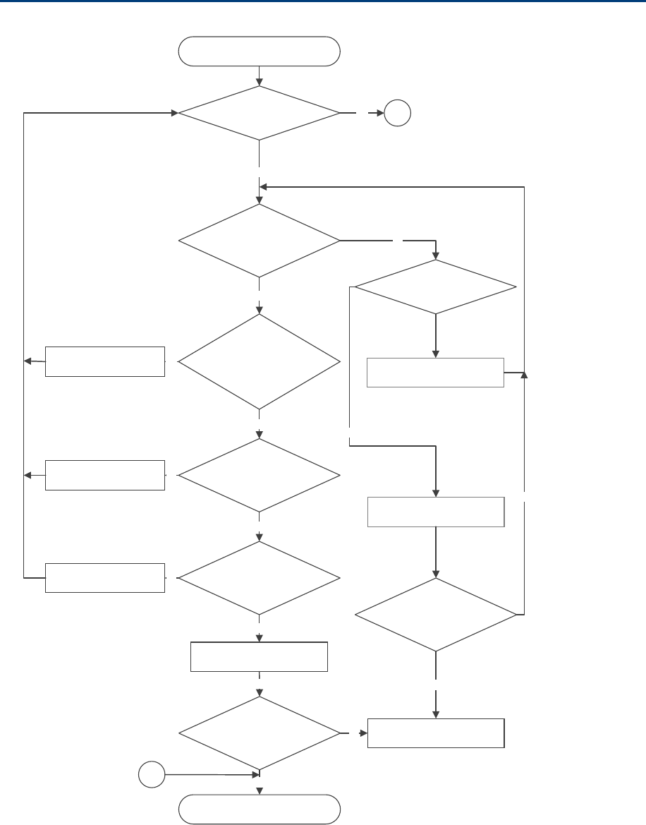
Chapter 11: Troubleshooting Power-up troubleshooting
Page 11-13
Power-up troubleshooting
ModuledoesnotpowerON
Isthe
LEDalwaysred?
IsthereACpower
goingtothesupply?
No
SwitchONACmainspower
Test cable,use known
goodcable.Couldtheradiobe
indefaultmode
Yes
Yes
Testcable?
No
Iscablelength<300meters?
Yes
Connecttoaknownpower
supply
Isthemodule’s
redLEDON?
Yes
Yes
ModuleispoweredON
Yes
Ethernetcable
repaired
ContactCambiumSupportfor
RMA
No
IsModule’spower
LEDON?
No
A
Yes
Cablewireandpinout
corrected
Cablelengthwithin
300meters
Yes
No
No
A
Connecttoknowngood
module
Ismodulegetting
poweredON?
No
Yes

Chapter 11: Troubleshooting Registration and connectivity troubleshooting
Page 11-14
Registration and connectivity
troubleshooting
SM/BMS Registration
If no SMs are registered to this AP, then the Session Status tab displays the simple message No
sessions. In this case, try the following steps.
1 More finely aim the SM or SMs toward the AP.
2 Recheck the Session Status tab of the AP for the presence of LUIDs.
3 If still no LUIDs are reported on the Session Status tab, click the Configuration button on
the left side of the Home page.
RESULT: The AP responds by opening the AP Configuration page.
4 Click the Radio tab.
5 Find the Color Code parameter and note the setting.
6 In the same sequence as you did for the AP directly under Configuring Link for Test on
Page 5-16, connect the SM to a computing device and to power.
7 On the left side of the SM Home page, click the Configuration button.
RESULT: The Configuration page of the SM opens.
8 Click the Radio tab.
9 If the transmit frequency of the AP is not selected in the Custom Radio Frequency Scan
Selection List parameter, select the frequency that matches.
10 If the Color Code parameter on this page is not identical to the Color Code parameter
you noted from the AP, change one of them so that they match.
11 At the bottom of the Radio tab for the SM, click the Save Changes button.
12 Click the Reboot button.
13 Allow several minutes for the SM to reboot and register to the AP.
14 Return to the computing device that is connected to the AP.
15 Recheck the Session Status tab of the AP for the presence of LUIDs.
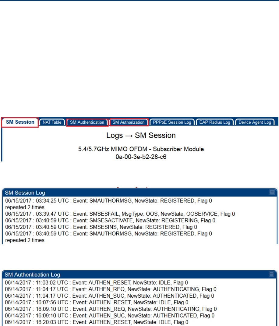
Chapter 11: Troubleshooting Logs
Page 11-15
Logs
Persistent Logging
PMP 450 SM supports logging information such as session logs, authentication logs, and authorization
logs that are persistent through reboots and connectivity losses.
Navigate to Logs to view:
SM Session
SM Authentication
SM Authorization
All the SM logs are saved to flash and displayed upon reboot.
Figure 202 SM Logs
Figure 203 SM Session log
Figure 204 SM Authentication log
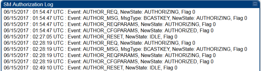
Chapter 11: Troubleshooting Logs
Page 11-16
Figure 205 SM Authorization log

Page I
Appendix A - 450m Reference
information
Specifications
Please see the Specification sheets listed on the Cambium Networks website for the most up-to-date
450m Series cnMedusa AP specifications:
http://www.cambiumnetworks.com/resources/pmp-450m/
450m overload
The 450m Series AP is designed to handle high load in terms of high throughput and high PPS. In terms
of throughput, 450m is designed to achieve 3x or more throughput improvement over 450 and 450i Series
products. In terms of packets per second (PPS), 450m is designed to handle up to 100k PPS.
Overload occurs when the offered load exceeds the above limits. When overload occurs, 450m will start
discarding packets and TCP throughput will degrade due to packet loss. The 450 family of products have
a set of overload statistics that can be used to monitor overload conditions (Statistics >Overload tab).
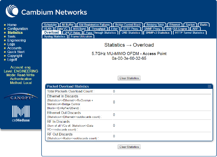
Chapter 11: Troubleshooting Logs
Page II
The above statistics shall be monitored over time for overload conditions over consecutive periods. Refer
to Interpreting Overload statistics for description of those statistics.
It’s worth noting that Frame Utilization statistics (Statistics >Frame Utilization tab: Frame Utilization:
Downlink and Uplink) are not necessarily indicative of overload condition. They show how much the TDD
frame is utilized. High frame utilization depends on:
1. high traffic during busy periods: those statistics will be close to 100% and almost all slots will be
utilized. In this case if the Overload statistics show that packets are discarded then this is an
indication of overload condition.
2. high percentage of VCs with low modulation with moderate traffic. Those VCs will require more slots
to service them (due to low modulation) and the frame utilization will be high. In this case the TDD
frame is fully utilized but the system is at low capacity and is not in an overload condition.
450m has higher PPS than 450 and 450i and supports higher throughput through spatial multiplexing,
therefore when a 450m replaces an overloaded 450 or 450i AP the 450m will not be overloaded under the
same conditions but the frame utilization may still show close to 100%; this should not alarm the
customer. The overload statistics shall be monitored on 450m to see if it is overloaded or not.

Chapter 11: Troubleshooting Logs
Page III
Glossary
Term Definition
10Base-T Technology in Ethernet communications that can deliver 10 Mb of data
across 328 feet (100 meters) of CAT 5 cable.
169.254.0.0 Gateway IP address default in Cambium fixed wireless broadband IP
network modules.
169.254.1.1 IP address default in Cambium fixed wireless broadband IP network
modules.
255.255.0.0 Subnet mask default in Cambium fixed wireless broadband IP network
modules and in Microsoft and Apple operating systems.
802.3 An IEEE standard that defines the contents of frames that are transferred
through Ethernet connections. Each of these frames contains a
preamble, the address to which the frame is sent, the address that sends
the frame, the length of the data to expect, the data, and a checksum to
validate that no contents were lost.
Access Point Cluster Two to six Access Point Modules that together distribute network or
Internet services to a community of subscribers. Each Access Point
Module covers a 60° or 90° sector. This cluster covers as much as 360°.
Also known as AP cluster.
Access Point Module Also known as AP. One module that distributes network or Internet
services in a 60° or 90° sector.
ACT/4 Second-from-left LED in the module. In the operating mode, this LED is
lit when data activity is present on the Ethernet link.
Address Resolution
Protocol
Protocol defined in RFC 826 to allow a network element to correlate a
host IP address to the Ethernet address of the host. See
http://www.faqs.org/rfcs/rfc826.html.
Aggregate Throughput The sum of the throughputs in the uplink and the downlink.
AP Access Point Module. One module that distributes network or Internet
services to subscriber modules.
ARP Address Resolution Protocol. A protocol defined in RFC 826 to allow a
network element to correlate a host IP address to the Ethernet address
of the host. See http://www.faqs.org/rfcs/rfc826.html.
APs MIB
Management Information Base file that defines objects that are specific
to the Access Point Module. See also Management Information Base.

Chapter 11: Troubleshooting Logs
Page IV
Term Definition
ASN.1 Abstract Syntax Notation One language. The format of the text files that
compose the Management Information Base.
Attenuation Reduction of signal strength caused by the travel from the transmitter to
the receiver, and caused by any object between. In the absence of
objects between, a signal that has a short wavelength experiences a
high degree of attenuation nevertheless.
BER Bit Error Rate. The ratio of incorrect data received to correct data
received.
BHM Backhaul Timing Master (BHM)- a module that is used in a point to point
link. This module controls the air protocol and configurations for the link..
BHS Backhaul Timing Slave (BHS)- a module that is used in a point to point
link. This module accepts configuration and timing from the master
module.
Bit Error Rate Ratio of incorrect data received to correct data received.
Box MIB Management Information Base file that defines module-level objects.
See also Management Information Base.
Bridge Network element that uses the physical address (not the logical address)
of another to pass data. The bridge passes the data to either the
destination address, if found in the simple routing table, or to all network
segments other than the one that transmitted the data. Modules are
Layer 2 bridges except that, where NAT is enabled for an SM, the SM is
a Layer 3 switch. Compare to Switch and Router, and see also NAT.
Buckets Theoretical data repositories that can be filled at preset rates or emptied
when preset conditions are experienced, such as when data is
transferred.
Burst Preset amount limit of data that may be continuously transferred.
CAT 5 Cable Cable that delivers Ethernet communications from module to module.
Later modules auto-sense whether this cable is wired in a straight-
through or crossover scheme.
CIR Committed Information Rate. For an SM or specified group of SMs, a
level of bandwidth that can be guaranteed to never fall below a specified
minimum (unless oversubscribed). In the Cambium implementation, this
is controlled by the Low Priority Uplink CIR, Low Priority Downlink CIR,
High Priority Uplink CIR, and High Priority Downlink CIR parameters.
Cluster Management
Module
Module that provides power, GPS timing, and networking connections for
an AP cluster. Also known as CMM4.
CMM Cluster Management Module. A module that provides power, GPS
timing, and networking connections for an Access Point cluster.

Chapter 11: Troubleshooting Logs
Page V
Term Definition
CodePoint See DiffServ.
Color Code Field Module parameter that identifies the other modules with which
communication is allowed. The range of valid values is 0 to 255.
Community String Field Control string that allows a network management station to access MIB
information about the module.
Connectorized The 450 Platform Family Connectorized Radio solution provide RF port
to connect external antenna. It gives flexibility to connect to a variety of
external antennas.
Country Code A parameter that offers multiple fixed selections, each of which
automatically implements frequency band range restrictions for the
selected country. Units shipped to countries other than the United States
must be configured with the corresponding Region Code and Country
Code to comply with local regulatory requirements.
CRCError Field This field displays how many CRC errors occurred on the Ethernet
controller.
Data Encryption Standard Over-the-air link option that uses secret 56-bit keys and 8 parity bits.
Data Encryption Standard (DES) performs a series of bit permutations,
substitutions, and recombination operations on blocks of data.
Demilitarized Zone Internet Protocol area outside of a firewall. Defined in RFC 2647. See
http://www.faqs.org/rfcs/rfc2647.html.
DES Data Encryption Standard. An over-the-air link option that uses secret
56-bit keys and 8 parity bits. DES performs a series of bit permutations,
substitutions, and recombination operations on blocks of data.
DFS See Dynamic Frequency Selection
DHCP Dynamic Host Configuration Protocol, defined in RFC 2131. Protocol that
enables a device to be assigned a new IP address and TCP/IP
parameters, including a default gateway, whenever the device reboots.
Thus DHCP reduces configuration time, conserves IP addresses, and
allows modules to be moved to a different network within the system.
See http://www.faqs.org/rfcs/rfc2131.html. See also Static IP Address
Assignment.

Chapter 11: Troubleshooting Logs
Page VI
Term Definition
DiffServ Differentiated Services, consistent with RFC 2474. A byte in the type of
service (TOS) field of packets whose values correlates to the channel on
which the packet should be sent. The value is a numeric code point.
Cambium modules map each of 64 code points to values of 0 through 7.
Three of these code points have fixed values, and the remaining 61 are
settable. Values of 0 through 3 map to the low-priority channel; 4 through
7 to the high-priority channel. The mappings are the same as 802.1p
VLAN priorities. (However, configuring DiffServ does not automatically
enable the VLAN feature.) Among the settable parameters, the values
are set in the AP for all downlinks within the sector and in the SM for
each uplink.
DMZ Demilitarized Zone as defined in RFC 2647. An Internet Protocol area
outside of a firewall. See http://www.faqs.org/rfcs/rfc2647.html.
Dynamic Frequency
Selection
A requirement in certain countries and regions for systems to detect
interference from other systems, notably radar systems, and to avoid co-
channel operation with these systems.
Dynamic Host Configuration
Protocol
See DHCP.
Electronic Serial Number Hardware address that the factory assigns to the module for identification
in the Data Link layer interface of the Open Systems Interconnection
system. This address serves as an electronic serial number. Same as
MAC Address.
ESN Electronic Serial Number. The hardware address that the factory assigns
to the module for identification in the Data Link layer interface of the
Open Systems Interconnection system. This address serves as an
electronic serial number. Same as MAC Address.
Ethernet Protocol Any of several IEEE standards that define the contents of frames that are
transferred from one network element to another through Ethernet
connections.
ETSI European Telecommunications Standards Institute
Fade Margin The difference between strength of the received signal and the strength
that the receiver requires for maintaining a reliable link. A higher fade
margin is characteristic of a more reliable link. Standard operating
margin.
FCC Federal Communications Commission of the U.S.A.
Field-programmable Gate
Array
Array of logic, relational data, and wiring data that is factory programmed
and can be reprogrammed.

Chapter 11: Troubleshooting Logs
Page VII
Term Definition
File Transfer Protocol Utility that transfers of files through TCP (Transport Control Protocol)
between computing devices that do not operate on the same platform.
Defined in RFC 959. See http://www.faqs.org/rfcs/rfc959.html.
FPGA Field-programmable Gate Array. An array of logic, relational data, and
wiring data that is factory programmed and can be reprogrammed.
Free Space Path Loss Signal attenuation that is naturally caused by atmospheric conditions and
by the distance between the antenna and the receiver.
Fresnel Zone Space in which no object should exist that can attenuate, diffract, or
reflect a transmitted signal before the signal reaches the target receiver.
FTP File Transfer Protocol, defined in RFC 959. Utility that transfers of files
through TCP (Transport Control Protocol) between computing devices
that do not operate on the same platform. See
http://www.faqs.org/rfcs/rfc959.html.
Global Positioning System Network of satellites that provides absolute time to networks on earth,
which use the time signal to synchronize transmission and reception
cycles (to avoid interference) and to provide reference for
troubleshooting activities.
GPS Global Positioning System. A network of satellites that provides absolute
time to networks on earth, which use the time signal to synchronize
transmission and reception cycles (to avoid interference) and to provide
reference for troubleshooting activities.
GPS/3 Third-from-left LED in the module. In the operating mode for an Access
Point Module, this LED is continuously lit as the module receives sync
pulse. In the operating mode for a Subscriber, this LED flashes on and
off to indicate that the module is not registered.
GUI Graphical user interface.
High-priority Channel Channel that supports low-latency traffic (such as Voice over IP) over
low-latency traffic (such as standard web traffic and file downloads). To
recognize the latency tolerance of traffic, this channel reads the IPv4
Type of Service DiffServ Control Point (DSCP) bits. Enabling the high-
priority channel reduces the maximum number of SMs that can be
served in the sector.
HTTP Hypertext Transfer Protocol, used to make the Internet resources
available on the World Wide Web. Defined in RFC 2068. See
http://www.faqs.org/rfcs/rfc2068.html.
HTTPS Hypertext Transfer Protocol Secure (HTTPS)

Chapter 11: Troubleshooting Logs
Page VIII
Term Definition
ICMP Internet Control Message Protocols defined in RFC 792, used to identify
Internet Protocol (IP)-level problems and to allow IP links to be tested.
See http://www.faqs.org/rfcs/rfc792.html.
Integrated The 450 Platform Family Integrated Radio solution provides integrated
antenna..
IP Internet Protocol defined in RFC 791. The Network Layer in the TCP/IP
protocol stack. This protocol is applied to addressing, routing, and
delivering, and re-assembling data packets into the Data Link layer of the
protocol stack. See http://www.faqs.org/rfcs/rfc791.html.
IP Address 32-bit binary number that identifies a network element by both network
and host. See also Subnet Mask.
IPv4 Traditional version of Internet Protocol, which defines 32-bit fields for
data transmission.
ISM Industrial, Scientific, and Medical Equipment radio frequency band, in the
900-MHz, 2.4-GHz, and 5.8-GHz ranges.
L2TP over IPSec Level 2 Tunneling Protocol over IP Security. One of several virtual
private network (VPN) implementation schemes. Regardless of whether
Subscriber Modules have the Network Address Translation feature
(NAT) enabled, they support VPNs that are based on this protocol.
Late Collision Field This field displays how many late collisions occurred on the Ethernet
controller. A normal collision occurs during the first 512 bits of the frame
transmission. A collision that occurs after the first 512 bits is considered
a late collision. A late collision is a serious network problem because the
frame being transmitted is discarded. A late collision is most commonly
caused by a mismatch between duplex configurations at the ends of a
link segment.
Line of Sight Wireless path (not simply visual path) direct from module to module. The
path that results provides both ideal aim and an ideal Fresnel zone.
LNK/5 Furthest left LED in the module. In the operating mode, this LED is
continuously lit when the Ethernet link is present. In the aiming mode for
a Subscriber Module, this LED is part of a bar graph that indicates the
quality of the RF link.
Logical Unit ID Final octet of the 4-octet IP address of the module.
LOS Line of sight. The wireless path (not simply visual path) direct from
module to module. The path that results provides both ideal aim and an
ideal Fresnel zone.
LUID Logical Unit ID. The final octet of the 4-octet IP address of the module.
Chapter 11: Troubleshooting Logs
Page IX
Term Definition
MAC Address Media Access Control address. The hardware address that the factory
assigns to the module for identification in the Data Link layer interface of
the Open Systems Interconnection system. This address serves as an
electronic serial number.
Management Information
Base
Space that allows a program (agent) in the network to relay information
to a network monitor about the status of defined variables (objects).
Maximum Information Rate
(MIR)
The cap applied to the bandwidth of an SM or specified group of SMs. In
the Cambium implementation, this is controlled by the Sustained Uplink
Data Rate, Uplink Burst Allocation, Sustained Downlink Data Rate, and
Downlink Burst Allocation parameters.
MIB Management Information Base. Space that allows a program (agent) in
the network to relay information to a network monitor about the status of
defined variables (objects).
MIR See Maximum Information Rate.
MU-MIMO Multi User- Multiple Input Multiple Output
NAT Network Address Translation defined in RFC 1631. A scheme that
isolates Subscriber Modules from the Internet. See
http://www.faqs.org/rfcs/rfc1631.html.
NEC National Electrical Code. The set of national wiring standards that are
enforced in the U.S.A.
NetBIOS Protocol defined in RFC 1001 and RFC 1002 to support an applications
programming interface in TCP/IP. This interface allows a computer to
transmit and receive data with another host computer on the network.
RFC 1001 defines the concepts and methods. RFC 1002 defines the
detailed specifications. See http://www.faqs.org/rfcs/rfc1001.html and
http://www.faqs.org/rfcs/rfc1002.html.
Network Address
Translation
Scheme that defines the Access Point Module as a proxy server to
isolate registered Subscriber Modules from the Internet. Defined in RFC
1631. See http://www.faqs.org/rfcs/rfc1631.html.
Network Management
Station
See NMS.
NMS Network Management Station. A monitor device that uses Simple
Network Management Protocol (SNMP) to control, gather, and report
information about predefined network variables (objects). See also
Simple Network Management Protocol.

Chapter 11: Troubleshooting Logs
Page X
Term Definition
Default Mode Device that enables the operator to regain control of a module that has
been locked by the No Remote Access feature, the 802.3 Link Disable
feature, or a password or IP address that cannot be recalled. This device
can be either fabricated on site or ordered.
PMP See Point-to-Multipoint Protocol.
Point-to-Multipoint Protocol Defined in RFC 2178, which specifies that data that originates from a
central network element can be received by all other network elements,
but data that originates from a non-central network element can be
received by only the central network element. See
http://www.faqs.org/rfcs/rfc2178.html. Also referenced as PMP.
PPPoE Point to Point Protocol over Ethernet. Supported on SMs for
operators who use PPPoE in other parts of their network operators who
want to deploy PPPoE to realize per-subscriber authentication, metrics,
and usage control.
PPS Packet Per Second
PPTP Point to Point Tunneling Protocol. One of several virtual private network
implementations. Regardless of whether the Network Address
Translation (NAT) feature enabled, Subscriber Modules support VPNs
that are based on this protocol.
Protective Earth Connection to earth (which has a charge of 0 volts). Also known as
ground.
Proxy Server Network computer that isolates another from the Internet. The proxy
server communicates for the other computer, and sends replies to only
the appropriate computer, which has an IP address that is not unique or
not registered.
PTP A Point-to-Point connection refers to a communications connection
between two nodes or endpoints.
Radio Signal Strength
Indicator
Relative measure of the strength of a received signal. An acceptable link
displays a Radio Signal Strength Indicator (RSSI) value of greater than
700.
Reflection Change of direction and reduction of amplitude of a signal that
encounters an object larger than the wavelength. Reflection may cause
an additional copy of the wavelength to arrive after the original,
unobstructed wavelength arrives. This causes partial cancellation of the
signal and may render the link unacceptable. However, in some
instances where the direct signal cannot be received, the reflected copy
may be received and render an otherwise unacceptable link acceptable.

Chapter 11: Troubleshooting Logs
Page XI
Term Definition
Region Code A parameter that offers multiple fixed selections, each of which
automatically implements frequency band range restrictions for the
selected region. Units shipped to regions other than the United States
must be configured with the corresponding Region Code to comply with
local regulatory requirements.
RF Radio frequency. How many times each second a cycle in the antenna
occurs, from positive to negative and back to positive amplitude.
RJ-12 Standard cable that is typically used for telephone line or modem
connection.
RJ-45 Standard cable that is typically used for Ethernet connection. This cable
may be wired as straight-through or as crossover. Later modules auto-
sense whether the cable is straight-through or crossover.
Router Network element that uses the logical (IP) address of another to pass
data to only the intended recipient. Compare to Switch and Bridge.
RSSI Radio Signal Strength Indicator. A relative measure of the strength of a
received signal. An acceptable link displays an RSSI value of greater
than 700.
Self-interference Interference with a module from another module in the same network.
SFP Small Form-factor Pluggable
Simple Network
Management Protocol
Standard that is used for communications between a program (agent) in
the network and a network management station (monitor). Defined in
RFC 1157. See http://www.faqs.org/rfcs/rfc1157.html.
SM Customer premises equipment (CPE) device that extends network or
Internet services by communication with an Access Point Module or an
Access Point cluster.
SNMP See Simple Network Management Protocol, defined in RFC 1157.
SNMPv3 SNMP version 3
SNMP Trap Capture of information that informs the network monitor through Simple
Network Management Protocol of a monitored occurrence in the module.
Static IP Address
Assignment
Assignment of Internet Protocol address that can be changed only
manually. Thus static IP address assignment requires more configuration
time and consumes more of the available IP addresses than DHCP
address assignment does. RFC 2050 provides guidelines for the static
allocation of IP addresses. See http://www.faqs.org/rfcs/rfc2050.html.
See also DHCP.
Chapter 11: Troubleshooting Logs
Page XII
Term Definition
Subnet Mask 32-bit binary number that filters an IP address to reveal what part
identifies the network and what part identifies the host. The number of
subnet mask bits that are set to 1 indicates how many leading bits of the
IP address identify the network. The number of subnet mask bits that are
set 0 indicate how many trailing bits of the IP address identify the host.
Subscriber Module Customer premises equipment (CPE) device that extends network or
Internet services by communication with an Access Point Module or an
Access Point cluster.
Sustained Data Rate Preset rate limit of data transfer.
Switch Network element that uses the port that is associated with the physical
address of another to pass data to only the intended recipient. Compare
to Bridge and Router.
Sync GPS (Global Positioning System) absolute time, which is passed from
one module to another. Sync enables timing that prevents modules from
transmitting or receiving interference. Sync also provides correlative time
stamps for troubleshooting efforts.
TCP Alternatively known as Transmission Control Protocol or Transport
Control Protocol. The Transport Layer in the TCP/IP protocol stack. This
protocol is applied to assure that data packets arrive at the target
network element and to control the flow of data through the Internet.
Defined in RFC 793. See http://www.faqs.org/rfcs/rfc793.html.
TDD Time Division Duplexing. Synchronized data transmission with some
time slots allocated to devices transmitting on the uplink and some to the
device transmitting on the downlink.
telnet Utility that allows a client computer to update a server. A firewall can
prevent the use of the telnet utility to breach the security of the server.
See http://www.faqs.org/rfcs/rfc818.html,
http://www.faqs.org/rfcs/rfc854.html and
http://www.faqs.org/rfcs/rfc855.html.
Tokens Theoretical amounts of data. See also Buckets.
TxUnderrun Field This field displays how many transmission-underrun errors occurred on
the Ethernet controller.
UDP User Datagram Protocol. A set of Network, Transport, and Session Layer
protocols that RFC 768 defines. These protocols include checksum and
address information but does not retransmit data or process any errors.
See http://www.faqs.org/rfcs/rfc768.html.
udp User-defined type of port.

Chapter 11: Troubleshooting Logs
Page XIII
Term Definition
U-NII Unlicensed National Information Infrastructure radio frequency band, in
the 5.1GHz through 5.8 GHz ranges.
VID VLAN identifier. See also VLAN.
VLAN Virtual local area network. An association of devices through software
that contains broadcast traffic, as routers would, but in the switch-level
protocol.
VPN Virtual private network for communication over a public network.
One typical use is to connect remote employees, who are at home or in a
different city, to their corporate network over the Internet. Any of several
VPN implementation schemes is possible. SMs support L2TP over IPSec
(Level 2 Tunneling Protocol over IP Security) VPNs and PPTP (Point to
Point Tunneling Protocol) VPNs, regardless of whether the Network
Address Translation (NAT) feature enabled.