Cambium Networks 50450M 5GHz Point to MultiPoint Multi User MIMO Access Point User Manual USERS MANUAL PART2
Cambium Networks Limited 5GHz Point to MultiPoint Multi User MIMO Access Point USERS MANUAL PART2
Contents
- 1. USER GUIDE P1
- 2. USER GUIDE P2
- 3. USER GUIDE P3
- 4. USER GUIDE P4
- 5. User manual
- 6. User Manual
- 7. USERS MANUAL PART1
- 8. USERS MANUAL PART2
- 9. USERS MANUAL PART3
- 10. USERS MANUAL PART4
- 11. USER MANUAL PART1
- 12. USER MANUAL PART2
- 13. USER MANUAL PART 3
- 14. USER MANUAL PART 4
- 15. USER MANUAL PT1
- 16. USER MANUAL PT2
- 17. USER MANUAL PT3
USERS MANUAL PART2
Chapter 6: Installation Installing an integrated ODU
Page 6-55
PMP/PTP 450i Series – AP/SM/BH
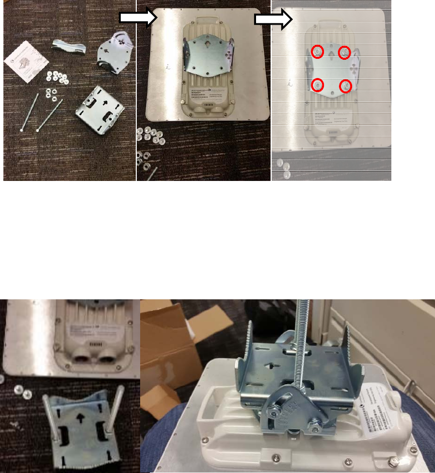
To mount and connect an integrated ODU, proceed as follows:
1 Fix the mounting plate to the back of the ODU using the four M6 bolts, and spring and plain washers
provided. Tighten the bolts to a torque setting of 5.0 Nm (3.7 lb ft).
Fi
g
ure 115 Fixing the mounting plate to the back of the ODU
2 Attach the bracket body to the mounting plate using the M8 bolt, spring and plain washers.
3 Hoist the ODU to the mounting position.
4 Attach the bracket body to the pole using the bracket clamp, M8 bolts, and spring and plain washers.
5 If the ODU is mounted outdoors, weatherproof the N type connectors (when antenna alignment is
complete) using PVC tape and self-amalgamating rubber tape.
Fi
g
ure 116 Attaching the bracket body
Chapter 6: Installation Connecting Cat5e Ethernet cable
Page 6-56
Connecting Cat5e Ethernet cable
Connecting an RJ45 and gland to a unit
Perform this task to connect the Ethernet cable to an AP.
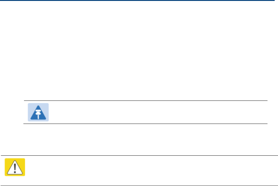
To connect the Ethernet cable with a gland to an AP unit, proceed as follows:
1 Insert the RJ45 cable through the gland components
2 Insert the RJ45 plug into the socket in the unit, making sure that the locking tab snaps home.
3 Support the drop cable and gently hand screw the gland body into the unit until the bushing seal is
flush to the unit body.
Note
Do not fit the back shell prior to securing the gland body.
4 Once the gland is fully hand screwed into the unit, tighten it one full rotation only with a 1 1/8 inch
spanner wrench.
5 When the gland body has been fitted, tighten the gland back shell.
Caution
Do not over-tighten the gland back shell, as the internal seal and structure or RJ45 port may
be damaged.
Chapter 6: Installation Connecting Cat5e Ethernet cable
Page 6-57
Figure 117 Ethernet cable gland for PMP/PTP 450 Series
Figure 118 Ethernet cable gland for PMP/PTP 450i Series
Chapter 6: Installation Connecting Cat5e Ethernet cable
Page 6-58
Disconnecting an RJ45 and gland from a unit
To disconnect the Ethernet cable and gland from a unit, proceed as follows:
1 Hold the Ethernet cable and remove the gland back shell.
2 Use a small flathead screwdriver (0.2”/5mm wide or greater) to gently release the black plastic
watertight bushing from the compression fins, being careful not to damage the bushing.
3 Unscrew the gland body from the AP, making sure that the Ethernet cable is not rotating while
disengaging the gland body from the AP housing.
4 Use a small screwdriver to depress the RJ45 locking clip.
5 Unplug the RJ45 cable.
6 Remove the gland from the cable, if necessary.

Chapter 6: Installation Installing ODU
Page 6-59
Installing ODU
Installing a 450 Platform Family AP
To install a 450 Platform Family AP, perform the following steps.
Procedure 5 Installing an AP
1 Begin with the AP in the powered-down state.
2 Choose the best mounting location for your particular application. Modules need not be
mounted next to each other. They can be distributed throughout a given site. However, the
60° offset must be maintained. Mounting can be done with supplied clamps.
See Installing external antennas to a connectorized ODU on page 6-23 for connecting an
external antenna to PMP 450i Series, PMP 450 Series, PMP 450i Series AP 900 MHz and
PMP 450 Series SM
See Installing an integrated ODU on page 6-52
3 Align the AP as follows:
a. Move the module to where the link will be unobstructed by the radio horizon and no
objects penetrate the Fresnel zone.
b. Use a local map, compass, and/or GPS device as needed to determine the direction
that one or more APs require to each cover the intended 60° sector.
c. Apply the appropriate degree of downward tilt.
d. Ensure that the nearest and furthest SMs that must register to this AP are within the
beam coverage area.
4 Adjust the azimuth to achieve visual alignment, lock the AP in the proper direction and
downward tilt.
5 Attach the cables to the AP (See Powering the AP/SM/BH for test configuration on Page 5-
16)
6 Waterproof the cables (See section Attaching and weatherproofing an N type connector on
page 6-69).

Chapter 6: Installation Installing ODU
Page 6-60
Installing a 450 Platform Family SM
Installing a 450 Platform Family SM consists of two procedures:
Physically installing the SM on a residence or other location and performing a coarse alignment using
the alignment tool or alignment tone.
Verifying the AP to SM link and finalizing alignment using review of power level, link tests, and review
of registration and session counts.
Procedure 6 Installing an SM
1 Choose the best mounting location for the SM based on section ODU and external
antenna location on page 3-10.
2 Use stainless steel hose clamps or equivalent fasteners to lock the SM into position.
See Installing external antennas to a connectorized ODU on page 6-23 for connecting
external antenna
See Installing an integrated ODU on page 6-52
3 Remove the base cover of the SM.
4 Terminate the UV outside grade Category 5 Ethernet cable with an RJ-45 connector, and
connect the cable to the SM.
5 Wrap a drip loop in the cable.
6 For Connectorized Models, Install the external antenna according to the manufacturer’s
instructions.
7 For Connectorized Models, connect the SM’s N-type antenna connectors to the external
antenna, ensuring that the polarity matches between the SM cable labeling and the
antenna port labels.
Connectorized SM Antenna Cable Label Antenna Connection
A Vertical
B Horizontal
8 For Connectorized Models, weatherproof the N-type antenna connectors following section
Attaching and weatherproofing an N type connector on page 6-69.
9 Wrap an AWG 10 (or 6mm2) copper wire around the Ground post of the SM
10 Securely connect the copper wire to the grounding system (Protective Earth) according to
applicable regulations.
11 Install a surge suppressor as described in the section Mount the Surge Suppressor on
page 6-10.
12 Connect the power supply to a power source.
13 Connect the Ethernet output from the Data port of the power supply to the Ethernet port of
your laptop.
Chapter 6: Installation Installing ODU
Page 6-61
14 Connect the drop cable from ODU to the Data+power port of the power suppy.
15 Launch your web browser. In the URL address bar, enter 169.254.1.1. then press Enter.
16 If the browser in laptop fails to access the interface of the SM, follow the procedure Radio
recovery mode on page 1-26
17 Log in as admin on the ODU. Configure a password for the admin account and log off.
18 Log back into the SM as admin or root, using the password that you configured.
19 For coarse alignment of the SM, use the Alignment Tool located at Tools, Alignment
Tool.
Optionally, connect a headset to the AUX/SYNC port on the SM and listen to the
alignment tone, which indicates greater SM receive signal power by pitch. By adjusting the
SM’s position until the highest frequency pitch is obtained operators and installers can be
confident that the SM is properly positioned. For information on device GUI tools available
for alignment, see sections Using the Alignment Tool, Using the Link Capacity Test tool,
and Using AP Evaluation tool below.
20 When the highest power is achieved, lock the SM mounting bracket in place.
21 Log off of the SM web interface.
22 Disconnect the Ethernet cable from your laptop.
23 Replace the base cover of the SM.
24 Connect the Ethernet cable to the computer that the subscriber will be using.
Installing a 450 Platform Family BHM
To install a 450 Platform Family BHM, perform the following steps.
Procedure 7 Installing a BHM
1 Choose the best mounting location for your particular application.
2 Align the BHM as follows:
a. Move the module to where the link will be unobstructed by the radio horizon and no
objects penetrate the Fresnel zone.
b. Use a local map, compass, and/or GPS device as needed to determine the direction
to the BHS.
c. Apply the appropriate degree of downward or upward tilt.
d. Ensure that the BHS is within the beam coverage area.
3 Using stainless steel hose clamps or equivalent fasteners, lock the BHM into position.
See Installing external antennas to a connectorized ODU on page 6-23 for connecting
external antenna
4 If this BHM will not be connected to a CMM, optionally connect a cable to a GPS timing
source and then to the SYNC port of the BHM.
Chapter 6: Installation Installing ODU
Page 6-62
5 Either connect the BHM’s Aux to the CMM or connect the DC power converter to the BHM
and then to an AC power source.
RESULT: When power is applied to a module or the unit is reset on the web-based
interface, the module requires approximately 25 seconds to boot. During this interval, self-
tests and other diagnostics are being performed.
6 Access Configuration > General page of the BHM for Synchronization configuration.
7 If a CMM4 is connected, set the Sync Input parameter to the AutoSync or Autosync +
Free Run selection.
Installing a 450 platform BHS
To install a PTP 450 platform Series BHS, perform the following steps.
Procedure 8 Installing a BHS
1 Choose the best mounting location for the BHS.
2 Terminate the UV outside grade Category 5 Ethernet cable with an RJ-45 connector, and
connect the cable to the BHS. (See Powering the AP/SM/BH for test configuration on
Page 5-16)
3 Use stainless steel hose clamps or equivalent fasteners to lock the BHS into position.
4 Install a surge suppressor as described in the section Mount the Surge Suppressor on
page 6-10
5 For coarse alignment of the BHS, use the Audible Alignment Tone feature as follows:
a. At the BHS, connect the RJ-45 connector of the Alignment Tool Headset to the Aux
port via an alignment tone adapter as shown in Figure 183 on page 8-19.
b. Listen to the alignment tone for pitch, which indicates greater signal power
(RSSI/dBm) by higher pitch.
Adjust the module slightly until you hear the highest pitch and highest volume
6 When you have achieved the best signal (highest pitch, loudest volume), lock the BHS in
place with the mounting hardware
Configuring the Link
See Configuring remote access on page 7-194.
Monitoring the Link
See Monitoring the Link on page 7-195.
Chapter 6: Installation Installing the AC Power Injector
Page 6-63
Installing the AC Power Injector
Caution
As the PSU is not waterproof, locate it away from sources of moisture, either in the
equipment building or in a ventilated moisture-proof enclosure. Do not locate the PSU in a
position where it may exceed its temperature rating.
Caution
Do not plug any device other than a PMP/PTP 450i Series ODU into the ODU port of the
PSU. Other devices may be damaged due to the non-standard techniques employed to
inject DC power into the Ethernet connection between the PSU and the ODU.
Do not plug any device other than a Cambium 450 Platform PSU into the PSU port of the
ODU. Plugging any other device into the PSU port of the ODU may damage the ODU and
device.
Installing the AC Power Injector
Follow this procedure to install the AC Power Injector:
1 Form a drip loop on the PSU end of the LPU to PSU drop cable. The drip loop ensures that any
moisture that runs down the cable cannot enter the PSU.
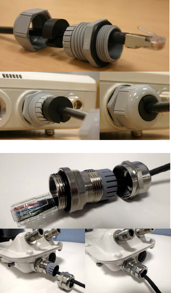
2 (a) Place the AC Power Injector on a horizontal surface. Plug the LPU to PSU drop cable into the
PSU port labeled ODU. (b) When the system is ready for network connection, connect the network
Cat5e cable to the LAN port of the PSU:
(a)
(b)

Chapter 6: Installation Installing CMM4
Page 6-64
Installing CMM4
Note
For instructions on CMM3 (CMMmicro) or CMM4 installation, including the outdoor
temperature range in which it is acceptable to install the unit, tools required, mounting
and cabling instructions, and connectivity verification, please see the PMP
Synchronization Solutions User Guide located on the Cambium website.
The Cluster Management Module 4 (CMM4) provides power, sync, and network connectivity for up to
eight APs, backhauls, and Ethernet terrestrial feeds in a variety of configurations. The CMM4 provides
Sync over Power over Ethernet and integrated surge suppression on the controller board for up to 8
APs or BHs. Both a custom 30 VDC power scheme and a custom 56 VDC power scheme are
available. Neither is the same as the later IEEE Standard 802.3af, and neither is compatible with it.
Managed switching using a hardened EtherWAN switch (1090CKHH models). The CMM4 ships with
a 14-port EtherWAN switch and is also available without a switch. The CMM4 originally shipped with
a 9-port EtherWAN switch.
Surge suppression on the controller board for the incoming 30V DC and 56V DC power lines and
GPS coax cable.
Auto-negotiation on the Ethernet ports. Ports will auto-negotiate to match inputs that are either
100Base-T or 10Base-T, and either full duplex or half duplex, when the connected device is set to
auto-negotiate. Alternatively, these parameters are settable.
An always-on NTP (Network Time Protocol) server that can provide date and time to any radio that
can reach the CMM’s management IP address.
CNUT can be used to upgrade the CMM-4 software.
450 Series and 450i Series can use the CMM4’s EtherWan switch for their network connectivity.
Note
The 56 V of a CMM4 needs to go through the adapter cable (part number
N000045L001A) as shown in Figure 34 on page 2-52.
A CMM4 56V power adapter cable can be prepared by swapping pins 5 and 7. See
CMM4 56 V power adapter cable pinout on page 2-52 for power adapter cable pinout.
Chapter 6: Installation Supplemental installation information
Page 6-65
Supplemental installation information
This section contains detailed installation procedures that are not included in the above topics, such as
how to strip cables, create grounding points and weatherproof connectors.
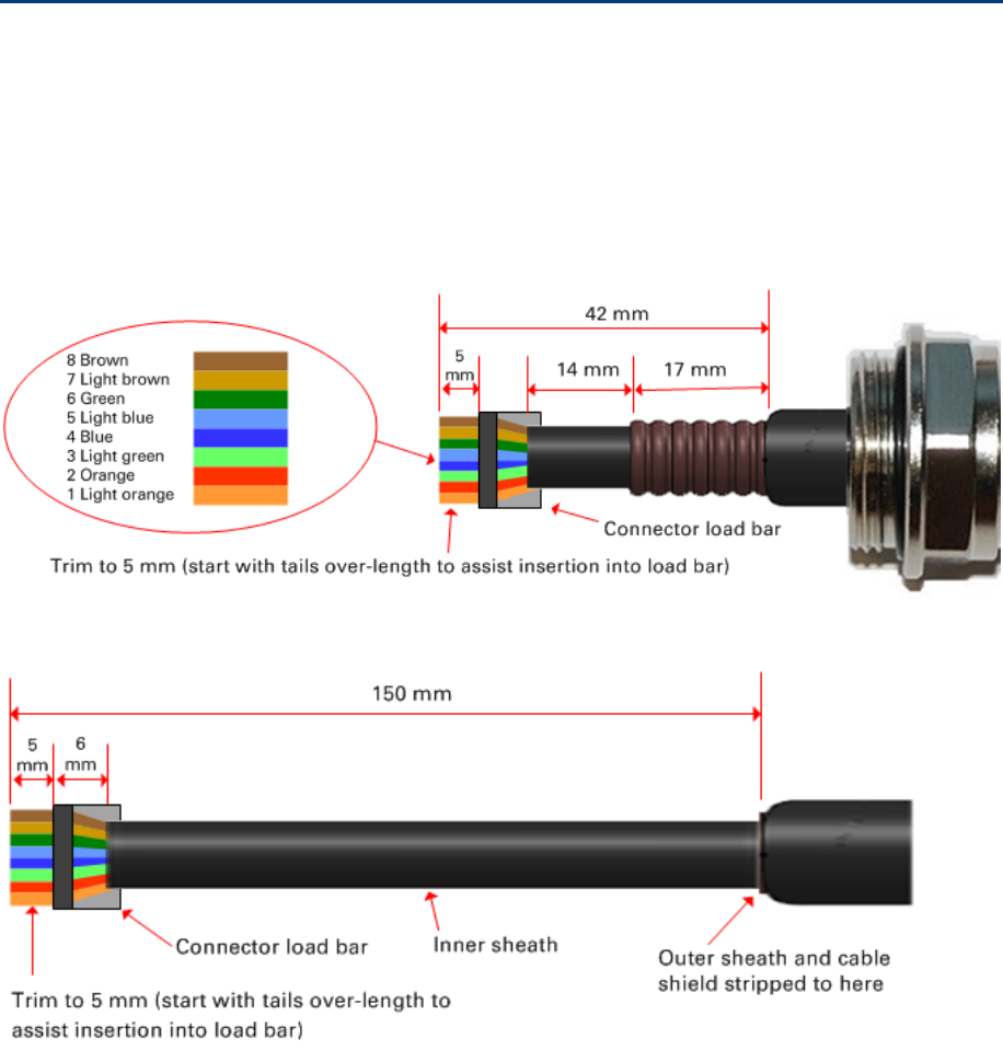
Stripping drop cable
When preparing the drop cable for connection to the 450 Platform Family ODU or LPU, use the following
measurements:
When preparing the drop cable for connection to the 450 Platform PSU (without a cable gland), use the
following measurements:
Chapter 6: Installation Supplemental installation information
Page 6-66
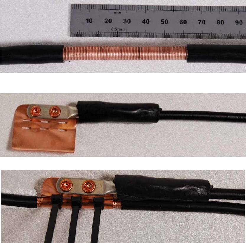
Creating a drop cable grounding point
Use this procedure to connect the screen of the main drop cable to the metal of the supporting structure
using the cable grounding kit (Cambium part number 01010419001).
To identify suitable grounding points, refer to Hazardous locations on page 3-15.
1 Remove 60 mm (2.5 inches) of the drop cable outer sheath.
2 Cut 38mm (1.5 inches) of rubber tape (self-amalgamating) and fit to the ground cable lug. Wrap the
tape completely around the lug and cable.
3 Fold the ground wire strap around the drop cable screen and fit cable ties.
Chapter 6: Installation Supplemental installation information
Page 6-67
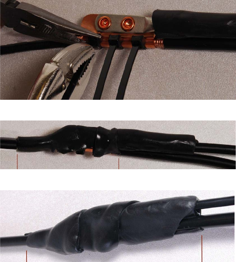
4 Tighten the cable ties with pliers. Cut the surplus from the cable ties.
5 Cut a 38mm (1.5 inches) section of self-amalgamating tape and wrap it completely around the joint
between the drop and ground cables.
6 Use the remainder of the self-amalgamating tape to wrap the complete assembly. Press the tape
edges together so that there are no gaps.
Chapter 6: Installation Supplemental installation information
Page 6-68
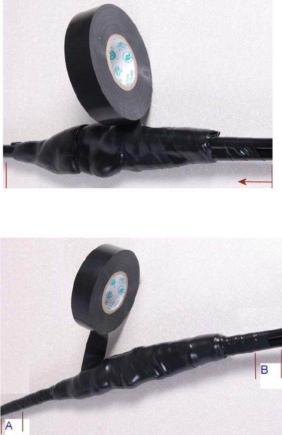
7 Wrap a layer of PVC tape from bottom to top, starting from 25 mm (1 inch) below and finishing
25 mm (1 inch) above the edge of the self-amalgamating tape, overlapping at half width.
8 Repeat with a further four layers of PVC tape, always overlapping at half width. Wrap the layers in
alternate directions (top to bottom, then bottom to top). The edges of each layer should be 25mm (1
inch) above (A) and 25 mm (1 inch) below (B) the previous layer.
9 Prepare the metal grounding point of the supporting structure to provide a good electrical contact
with the grounding cable clamp. Remove paint, grease or dirt, if present. Apply anti-oxidant
compound liberally between the two metals.
10 Clamp the bottom lug of the grounding cable to the supporting structure using site approved
methods. Use a two-hole lug secured with fasteners in both holes. This provides better protection
than a single-hole lug.
Chapter 6: Installation Supplemental installation information
Page 6-69
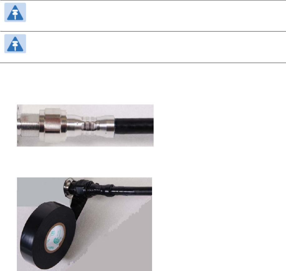
Attaching and weatherproofing an N type connector
The following procedure should be used to weatherproof the N type connectors fitted to the connectorized
ODU (AP/SM/BH) and antenna. This procedure must be followed to ensure that there is no moisture
ingress at the radio ports. Failure to properly seal N-type antenna connectors can result in poor link
performance or complete loss of radio communication.
Note
Cambium recommends to assemble the antenna, attach the ODU and cabling, and to seal
the RF connections before installing the unit at the deployment site.
Note
N type connectors should be tightened using a torque wrench, set to 15 lb in or 1.7 Nm. If a
torque wrench is not available, N type connectors may be finger tightened.
Use this procedure to weatherproof the N type connectors fitted to the connectorized ODU and external
antenna (if recommended by the antenna manufacturer).
1 Ensure the connection is tight. A torque wrench should be used if available:
2 Wrap the connection with a layer of 19 mm (0.75 inch) PVC tape, starting 25 mm (1 inch) below the
connector body. Overlap the tape to half-width and extend the wrapping to the body of the LPU.
Avoid making creases or wrinkles:
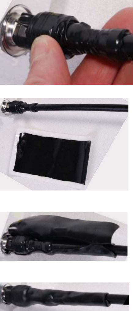
Chapter 6: Installation Supplemental installation information
Page 6-70
3 Smooth the tape edges:
4 Cut a 125mm (5 inches) length of rubber tape (self-amalgamating):
5 Expand the width of the tape by stretching it so that it will wrap completely around the connector
and cable:
6 Press the tape edges together so that there are no gaps. The tape should extend 25 mm (1 inch)
beyond the PVC tape:

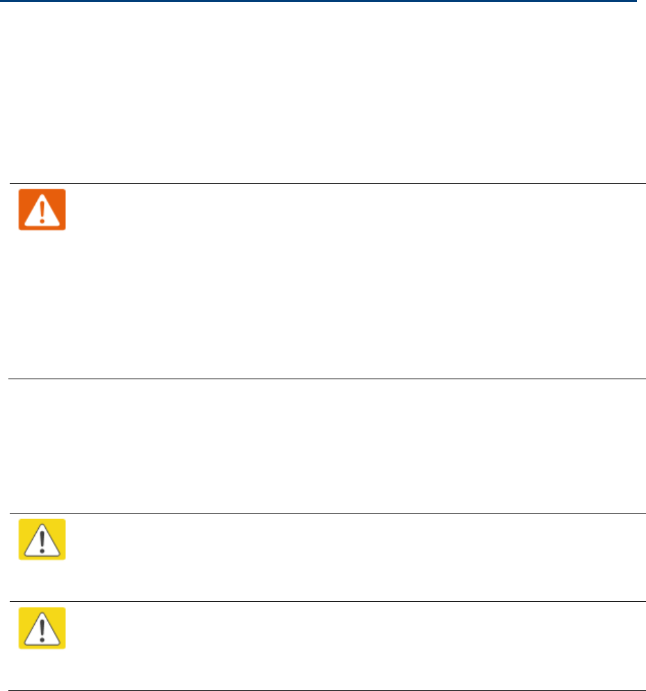
Chapter 6: Installation Supplemental installation information
Page 6-71
7 Wrap a layer of 50 mm (2 inch) PVC tape from bottom to top, starting from 25 mm (1 inch) below the
edge of the self-amalgamating tape, overlapping at half width.
8 Repeat with a further four layers of 19 mm (0.75 inch) PVC tape, always overlapping at half width.
Wrap the layers in alternate directions:
Second layer: top to bottom.
Third layer: bottom to top.
Fourth layer: top to bottom.
Fifth layer: bottom to top.
The bottom edge of each layer should be 25 mm (1 inch) below the previous layer.
9 Check the completed weatherproof connection:
Note
A video of this procedure can be found at:
https://www.youtube.com/watch?v=a-twPfCVq4A

Page 7-1
Chapter 7: Configuration
This chapter describes how to use the web interface to configure the 450 Platform link. This chapter
contains the following topics:
Preparing for configuration on page 7-2
Connecting to the unit on page 7-3
Using the web interface on page 7-5
Quick link setup on page 7-11
Configuring IP and Ethernet interfaces on page 7-22
Upgrading the software version and using CNUT on page 7-64
General configuration on page 7-68
Configuring Unit Settings page on page 7-91
Setting up time and date on page 7-95
Configuring synchronization on page 7-97
Configuring security on page 7-99
Configuring radio parameters on page 7-126
Setting up SNMP agent on page 7-180
Configuring syslog on page 7-188
Configuring remote access on page 7-194
Monitoring the Link on page 7-195
Configuring quality of service on page 7-198
Installation Color Code on page 7-211
Zero Touch Configuration Using DHCP Option 66 on page 7-212
Configuring Radio via config file on page 7-218
Configuring a RADIUS server on page 7-226
Chapter 7: Configuration Preparing for configuration
Page 7-2
Preparing for configuration
This section describes the checks to be performed before proceeding with unit configuration and antenna
alignment.
Safety precautions
All national and local safety standards must be followed while configuring the units and aligning the
antennas.
Warning
Ensure that personnel are not exposed to unsafe levels of RF energy. The units start to
radiate RF energy as soon as they are powered up. Respect the safety standards defined in
Compliance with safety standards on page 4-22, in particular the minimum separation
distances.
Observe the following guidelines:
Never work in front of the antenna when the ODU is powered.
Always power down the PSU before connecting or disconnecting the drop cable from the
PSU, ODU or LPU.
Regulatory compliance
All applicable radio regulations must be followed while configuring the units and aligning the antennas.
For more information, refer to Compliance with radio regulations on page 4-34.
Caution
If the system designer has provided a list of channels to be barred for TDWR radar
avoidance, the affected channels must be barred before the units are allowed to radiate on
site, otherwise the regulations will be infringed.
Attention
Si le concepteur du système a fourni une liste de canaux à interdire pour éviter les radars
TDWR, les cannaux concernées doivent être interdits avant que les unités sont autorisées à
émettre sur le site, sinon la réglementation peut être enfreinte.
Chapter 7: Configuration Connecting to the unit
Page 7-3
Connecting to the unit
This section describes how to connect the unit to a management PC and power it up.
Configuring the management PC
Use this procedure to configure the local management PC to communicate with the 450 Platform ODU.
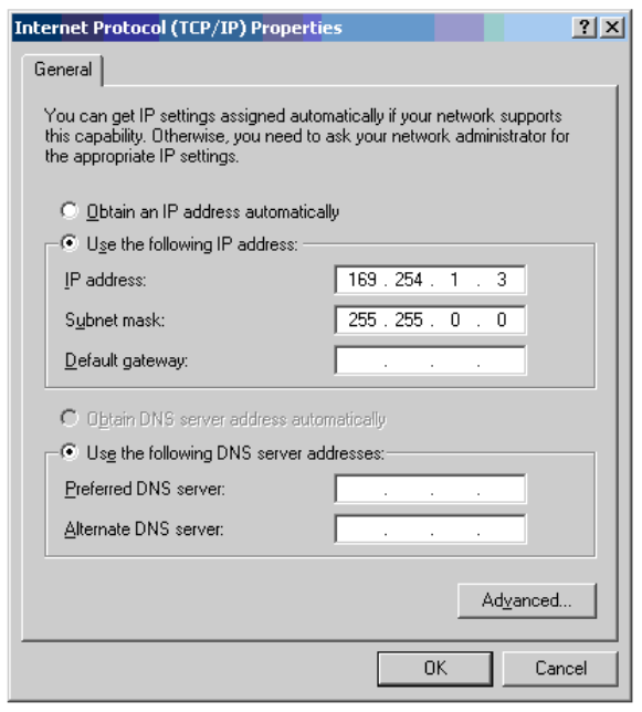
Procedure 9 Configuring the management PC
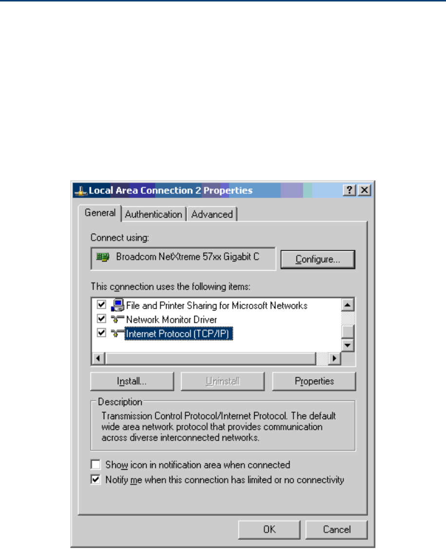
1 Select Properties for the Ethernet port. In Windows 7 this is found in Control Panel >
Network and Internet > Network Connections > Local Area Connection.
2 Select Internet Protocol (TCP/IP):
3 Click Properties.
Chapter 7: Configuration Connecting to the unit
Page 7-4
4 Enter an IP address that is valid for the 169.254.X.X network, avoiding 169.254.0.0 and
169.254.1.1. A good example is 169.254.1.3:
5 Enter a subnet mask of 255.255.0.0. Leave the default gateway blank.
Connecting to the PC and powering up
Use this procedure to connect a management PC and power up the 450 platform ODU.
Procedure 10 Connecting to the PC and powering up
1 Check that the ODU and PSU are correctly connected.
2 Connect the PC Ethernet port to the LAN port of the PSU using a standard (not crossed)
Ethernet cable.
3 Apply mains or battery power to the PSU. The green Power LED should illuminate
continuously.
4 After about several seconds, check that the orange Ethernet LED starts with 10 slow
flashes.
5 Check that the Ethernet LED then illuminates continuously.
Chapter 7: Configuration Using the web interface
Page 7-5
Using the web interface
This section describes how to log into the 450 Platform Family web interface and use its menus.
Logging into the web interface
Use this procedure to log into the web interface as a system administrator.
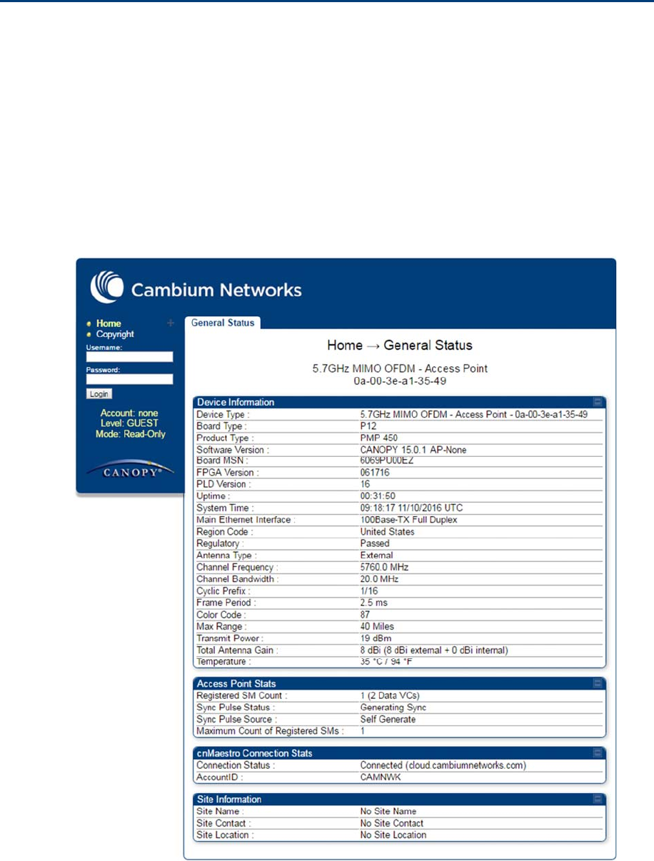
Procedure 11
Logging into the web interface
1
Start the web browser from the management PC.
2
Type the IP address of the unit into the address bar. The factory default IP address is
169.254.1.1
.
Press ENTER. The web interface menu and System Summary page are displayed:
Chapter 7: Configuration Using the web interface
Page 7-6
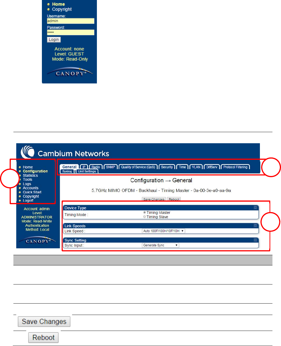
3
On left hand side of home page, the login information is displayed:
4
Enter Username (factory default username is
admin
) and Password (factory default password is
admin
) and click
Login
.
Web GUI
Field Name Description
Main Manu Click an option in side navigation bar (area marked as “1”). Multiple options
in sub-navigation bars appear
Menu Option Click top sub-navigation bar to choose one configuration page (area marked
as “2”)
Parameter To configure the parameters (e.g. area marked as “3”)
Press "Save Changes" to confirm and save the changes
To reboot the ODU
1
1
2
3
Chapter 7: Configuration Using the web interface
Page 7-7
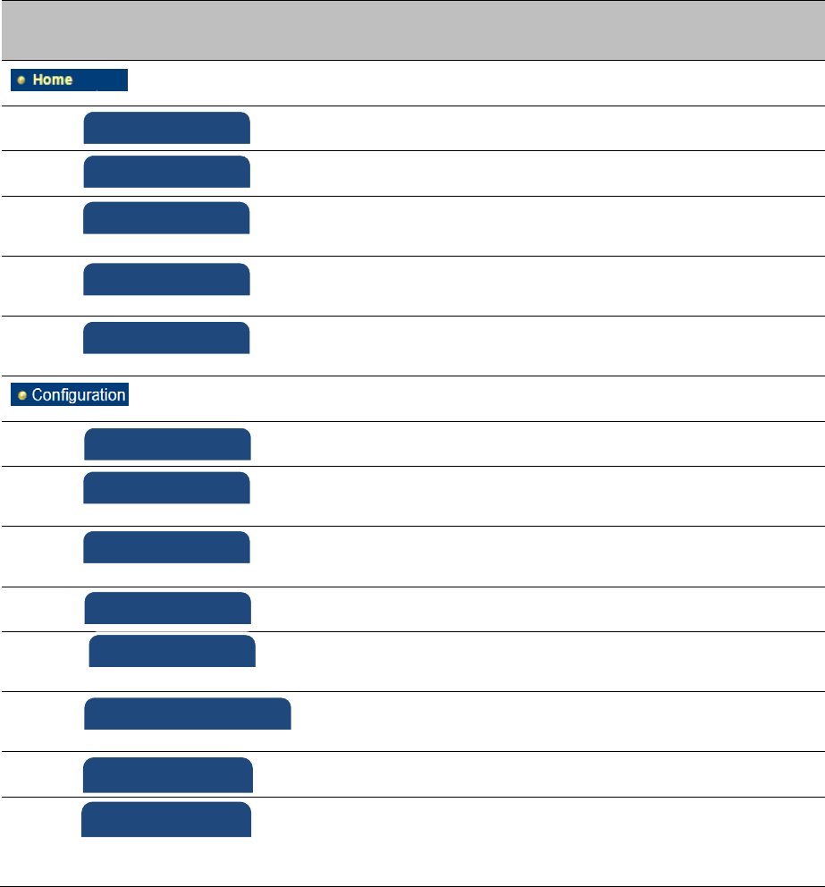
Using the menu options
Use the menu navigation bar in the left panel to navigate to each web page. Some of the menu options
are only displayed for specific system configurations. Use Table 101 to locate information about using
each web page.
Table 101 Menu options and web pages
Main
menu
Menu options Applicable
module
Description
All Viewing General Status on page 9-2
AP, BHM Viewing Session Status on page 9-20
All Interpreting messages in the Event Log
on page 9-29
AP, BHM Viewing the Network Interface on page
9-32
All Viewing the Layer 2 Neighbors on page
9-32
All General configuration on page 7-68
All Configuring IP and Ethernet interfaces
on page 7-22
All Configuring radio parameters on page 7-
127
All Setting up SNMP agent on page 7-180
All Configuring cnMaestroTM Connectivity
on page 7-220
All Configuring quality of service on page 7-
198
All Configuring security on page 7-99
AP, BHM Setting up time and date
Time page of 450 Platform Family -
AP/BHM on page 7-95
Event Lo
g
Network Interface
General
IP
Radio
SNMP
Qualit
y
of Service
(
QoS
)
Security
Time
La
y
er 2 Nei
g
hbors
Session Status
General Status
cnMaestro
Chapter 7: Configuration Using the web interface
Page 7-8
Main
menu
Menu options Applicable
module
Description
All VLAN configuration for PMP on page 7-
43
VLAN configuration for PTP on page 7-
53
All IPv4 and IPv6 Prioritization on page 7-60
All Filtering protocols and ports on page 7-
61
All Configuring syslog on page 7-188
All Configuring Ping Watchdog on page 7-
267
All Configuring Unit Settings page on page
7-91
All Viewing the Scheduler statistics on page
9-33
AP, BHM Viewing list of Registration Failures
statistics on page 9-35
All Interpreting Bridge Control Block
statistics on page 9-19
All Interpreting Bridging Table statistics on
page 9-37
All Interpreting Ethernet statistics on page
9-38
All Interpreting RF Control Block statistics
on page 9-41
All Interpreting VLAN statistics on page 9-2
All Interpreting Data VC statistics on page
9-4
AP, BHM Interpreting Throughput statistics on
page 9-6
SM Interpreting Filter statistics on page 9-12
SM Viewing ARP statistics on page 9-13
All Interpreting Overload statistics on page
9-9
VLAN
DiffServ
Protocol Filterin
g
S
y
slo
g
Unit Settin
g
Scheduler
Re
g
istration Failures
Brid
g
e Control Block
Brid
g
in
g
Table
Ethernet
Radio
VLAN
Data VC
Throu
g
h
p
ut
Filter
ARP
Overload
Pin
g
Watchdo
g
Chapter 7: Configuration Using the web interface
Page 7-9
Main
menu
Menu options Applicable
module
Description
All Interpreting syslog statistics on page 9-
25
SM Interpreting Translation Table statistics
on page 9-37
SM Interpreting DHCP Relay statistics on
page 9-10
SM Viewing NAT statistics on page 9-13
SM Viewing NAT DHCP Statistics on page
9-15
AP Interpreting Pass Through Statistics on
page 9-22
AP Interpreting Sync Status statistics on
page 9-16
SM Interpreting PPPoE Statistics for
Customer Activities on page 9-17
All Interpreting SNMPv3 Statistics on page
9-23
Interpreting Frame Utilization statistics
on page 9-23
All Using the Link Capacity Test tool on
page 8-21
All Spectrum Analyzer tool on page 8-3
All Remote Spectrum Analyzer tool on page
8-11
SM, BHS Using AP Evaluation tool on page 8-31
Using BHM Evaluation tool on page 8-35
AP Using the Subscriber Configuration tool
on page 8-43
AP, BHM Using the OFDM Frame Calculator tool
on page 8-39
SM Using BER Results tool on page 8-49
SM, BHS Using the Alignment Tool on page 8-14
S
y
slo
g
Statistics
Link Ca
p
acit
y
Test
S
p
ectrum Anal
y
zer
Remote S
p
ectrum Anal
y
zer
OFDM Frame Calculator
AP/BHM Evaluation
BER results
Translation Table
DHCP Rela
y
NAT Stats
NAT DHCP
S
y
nc Status
PPPoE
SNMPv3 Statistics
Pass Throu
g
h Statistics
Frame Utilization
Ali
g
nment Tool
Subscriber Confi
g
uration
Chapter 7: Configuration Using the web interface
Page 7-10
Main
menu
Menu options Applicable
module
Description
AP Using the Link Status tool on page 8-44
AP Using the Sessions tool on page 8-50
All Using the Ping Test tool on page 8-51
Changing a User Setting on page 7-101
Adding a User for Access to a module on
page 7-100
Deleting a User from Access to a module
on page 7-101
Users account on page 7-102
AP, BHM Quick link setup on page 7-11
AP, BHM Quick link setup on page 7-11
AP, BHM Quick link setup on page 7-11
AP, BHM Quick link setup on page 7-11
AP, BHM Quick link setup on page 7-11
AP, BHM Quick link setup on page 7-11
SM The PDA web-page includes 320 x 240
pixel formatted displays of information
important to installation and alignment
for installers using legacy PDA devices.
All device web pages are compatible
with touch devices such as smart
phones and tablets.
SM
SM
SM
SM
Link Status
Sessions
Chan
g
e User Settin
g
Add user
Delete User
User
Quick Start
S
y
nchronization
LAN IP Address
Re
g
ion Settin
g
s
Radio Carrier Fre
q
uenc
y
Review and Save Confi
g
uration
Quick Status
S
p
ectrum Results
(
PDA
)
Information
BHM Evaluation
AIM
Pin
g
Test

Chapter 7: Configuration Using the web interface
Page 7-11
Main
menu
Menu options Applicable
module
Description
All The Copyright web-page displays
pertinent device copyright information.
All
Co
py
ri
g
ht Notices
Chapter 7: Configuration Quick link setup
Page 7-12
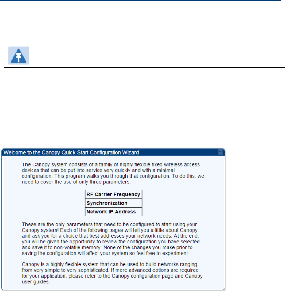
Quick link setup
This section describes how to use the Quick Start Wizard to complete the essential system configuration
tasks that must be performed on a PMP/PTP configuration.
Note
If the IP address of the AP or BHM is not known, See Radio recovery mode on page 1-26.
Initiating Quick Start Wizard
Applicable products PMP : AP PTP:
BHM
To start with Quick Start Wizard: after logging into the web management interface click the Quick Start
button on the left side of main menu bar. The AP/BHM responds by opening the Quick Start page.
Figure 119 Disarm Installation page (top and bottom of page shown)
Quick Start is a wizard that helps you to perform a basic configuration that places an AP/BHM into
service. Only the following parameters must be configured:
Region Code
RF Carrier Frequency
Synchronization
LAN (Network) IP Address
In each Quick Start page, you can
specify the settings to satisfy the requirements of the network.
review the configuration selected.
Chapter 7: Configuration Quick link setup
Page 7-13
save the configuration to non-volatile memory.
Procedure 12 Quick start wizard
1 At the bottom of the Quick Start tab, click the Go To Next Page button.
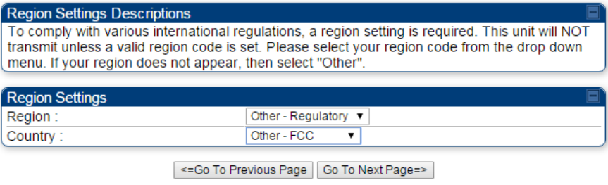
2 From the pull-down menu, select the region in which the AP will operate.
Figure 120 Regional Settings tab of AP/BHM
3 Click the Go To Next Page button.
Chapter 7: Configuration Quick link setup
Page 7-14
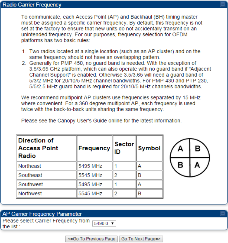
4 From the pull-down menu, select a frequency for the test.
Figure 121 Radio Carrier Frequency tab of AP/BHM
5 Click the Go To Next Page button.
Chapter 7: Configuration Quick link setup
Page 7-15
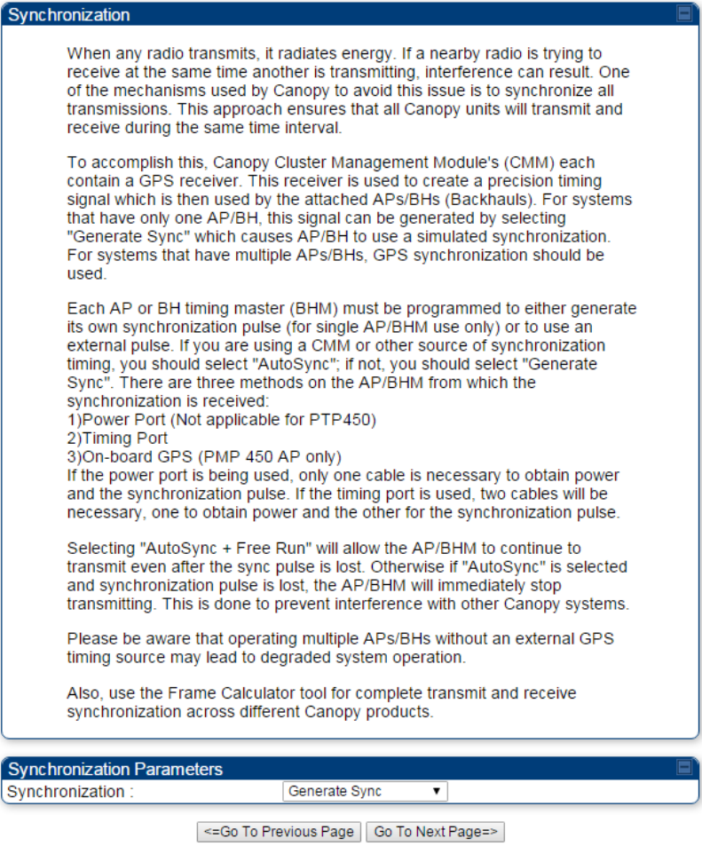
6 At the bottom of this tab, select Generate Sync Signal.
Figure 122 Synchronization tab of AP/BHM
7 Click the Go To Next Page button.
Chapter 7: Configuration Quick link setup
Page 7-16
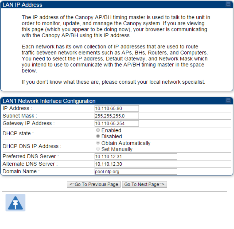
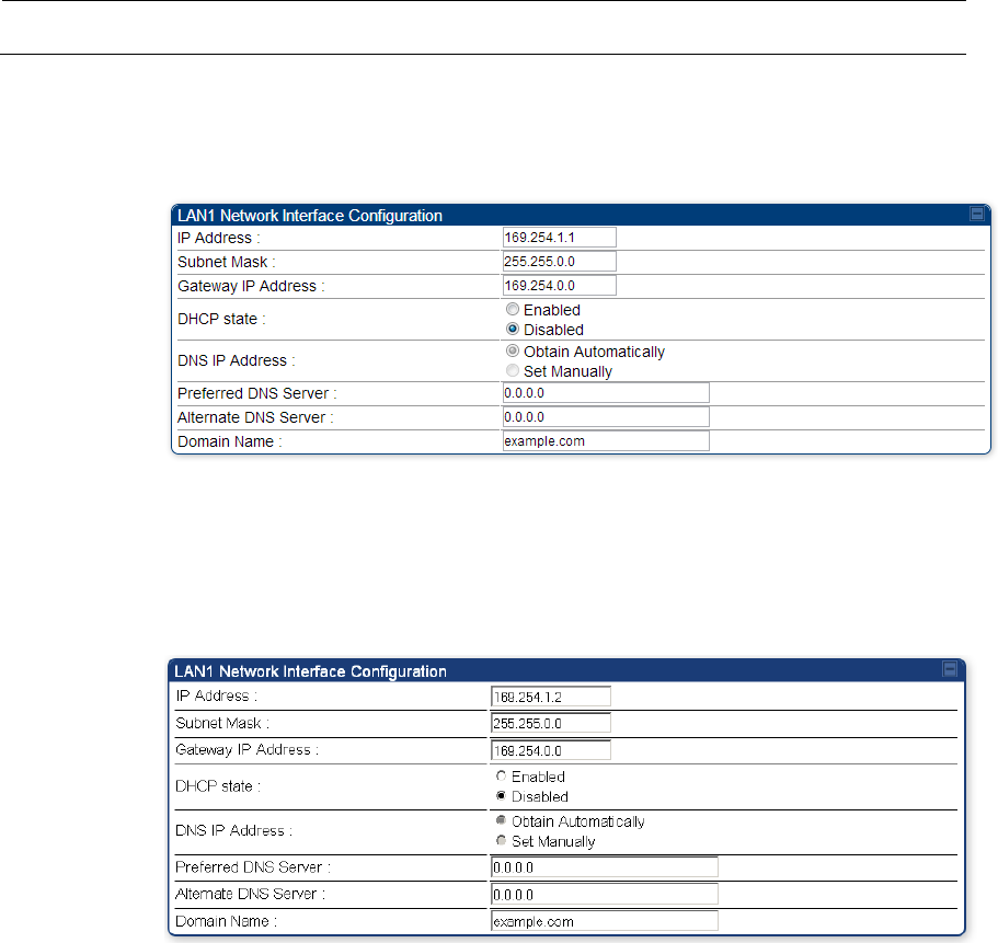
8 At the bottom of the IP address configuration tab, either
specify an IP Address, a Subnet Mask, and a Gateway IP Address for management of the AP
and leave the DHCP state set to Disabled.
set the DHCP state to Enabled to have the IP address, subnet mask, and gateway IP address
automatically configured by a domain name server (DNS).
Figure 123 LAN IP Address tab of the AP/BHM
Note
Cambium encourages you to experiment with the interface. Unless you save
a configuration and reboot the AP after you save the configuration, none of
the changes are affected.
9 Click the Go To Next Page => button.
Chapter 7: Configuration Quick link setup
Page 7-17
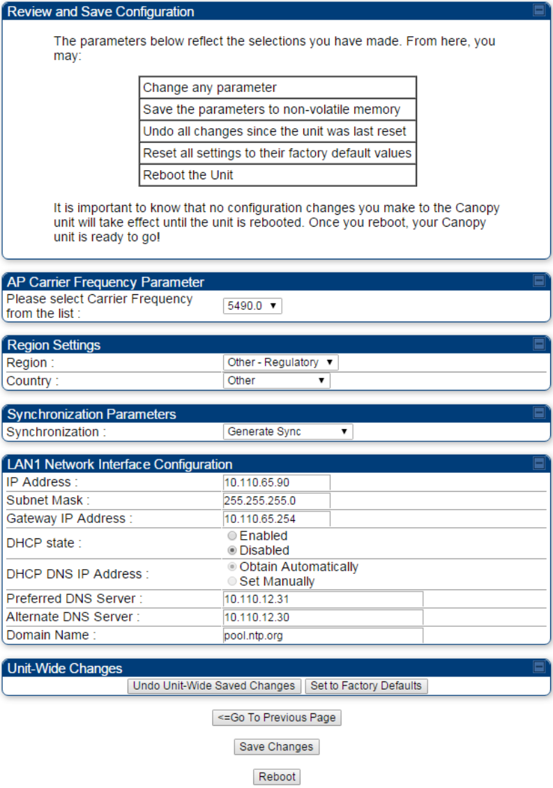
10 Ensure that the initial parameters for the AP are set as you intended.
Figure 124 Review and Save Configuration tab of the AP/BHM
11 Click the Save Changes button.
12 Click the Reboot button.
RESULT: The AP responds with the message Reboot Has Been Initiated…
Chapter 7: Configuration Quick link setup
Page 7-18
13 Wait until the indicator LEDs are not red.
14 Trigger your browser to refresh the page until the AP redisplays the General Status tab.
15 Wait until the red indicator LEDs are not lit.
Configuring time settings
Applicable products PMP : AP PTP:
BHM
To proceed with the test setup, click the Configuration link on the left side of the General Status page.
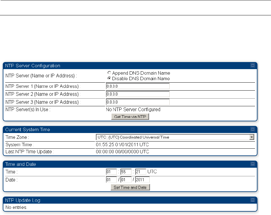
When the AP responds by opening the Configuration page to the General page, click the Time tab.
Figure 125 Time tab of the AP/BHM
To have each log in the AP/BHM correlated to a meaningful time and date, either a reliable network
element must pass time and date to the AP/BHM or you must set the time and date whenever a power
cycle of the AP/BHM has occurred. A network element passes time and date in any of the following
scenarios:
A connected CMM4 passes time and date (GPS time and date, if received).
A separate NTP server is addressable from the AP/BHM.
If the AP/BHM should obtain time and date from a CMM4, or a separate NTP server, enter the IP address
of the CMM4 or NTP server on this tab. To force the AP/BHM to obtain time and date before the first (or
next) 15-minute interval query of the NTP server, click Get Time through NTP.
Chapter 7: Configuration Quick link setup
Page 7-19
If you enter a time and date, the format for entry is
Figure 126 Time and date entry formats
Time : hh / mm / ss
Date : MM / dd /yyyy
where
hh represents the two-digit hour in the range 00 to 24
mm represents the two-digit minute
ss represents the two-digit second
MM represents the two-digit month
dd represents the two-digit day
yyyy represents the four-digit year
Proceed with the time setup as follows.
Procedure 13 Entering AP/BHM time setup information
1 Enter the appropriate information in the format shown above.
2 Then click the Set Time and Date button.
Note
The time displayed at the top of this page is static unless your browser is
set to automatically refresh
Powering the SM/BHS for test
Procedure 14 Powering the SM/BHS for test
1 In one hand, securely hold the top (larger shell) of the SM/BHS. With the other hand,
depress the lever in the back of the base cover (smaller shell). Remove the base cover.
2 Plug one end of a CAT 5 Ethernet cable into the SM PSU port
3 Plug the other end of the Ethernet cable into the jack in the pig tail that hangs from the
power supply
4 Roughly aim the SM/BHS toward the AP/BHM
5 Plug the power supply into an electrical outlet
Warning
From this point until you remove power from the AP/BHM, stay at least as
far from the AP/BHM as the minimum separation distance specified in
Calculated distances and power compliance margins.
6 Repeat the foregoing steps for each SM/BHS that you wish to include in the test.

Chapter 7: Configuration Quick link setup
Page 7-20
Viewing the Session Status of the AP/BHM to
determine test registration
Once the SMs/BHS under test are powered on, return to the computing device to determine if the
SM/BHS units have registered to the AP/BHM.
Note
In order for accurate power level readings to be displayed, traffic must be present on the
radio link.
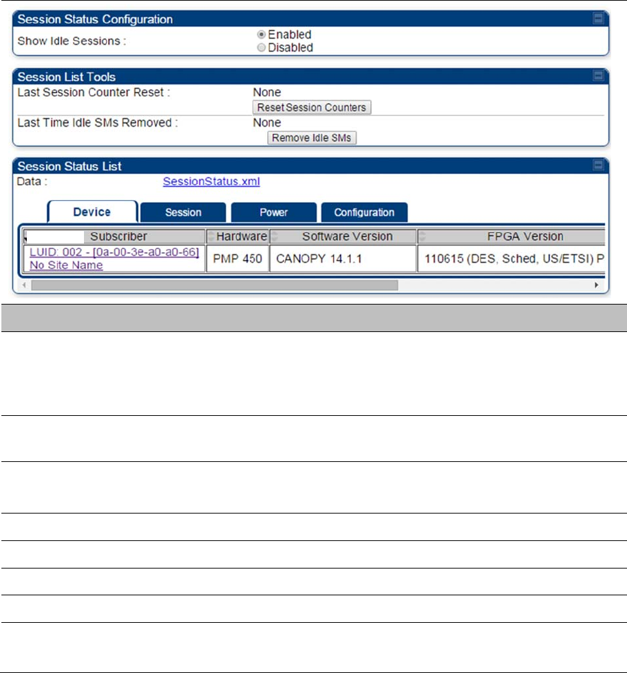
The Session Status tab provides information about each SM/BHS that has registered to the AP/BHM.
This information is useful for managing and troubleshooting a system. All information that you have
entered in the Site Name field of the SM/BHS displays in the Session Status tab of the linked AP/BHM.
The Session Status tab also includes the current active values on each SM( or BHS) (LUID) for MIR, and
VLAN, as well as the source of these values (representing the SM/BHS itself, Authentication Server, or
the AP/BHM and cap, if any—for example, APCAP as shown above).. As an SM/BHS registers to
the AP/BHM, the configuration source that this page displays for the associated LUID may change. After
registration, however, the displayed source is stable and can be trusted.
Idle subscribers may be included or removed from the session status display by enabling or disabling,
respectively, the Show Idle Sessions parameter. Enabling or disabling this parameter only affects the
GUI display of subscribers, not the registration status.
The SessionStatus.xml hyperlink allows user to export session status page from web management
interface of AP/BHM. The session status page will be exported in xml file.
Chapter 7: Configuration Quick link setup
Page 7-21
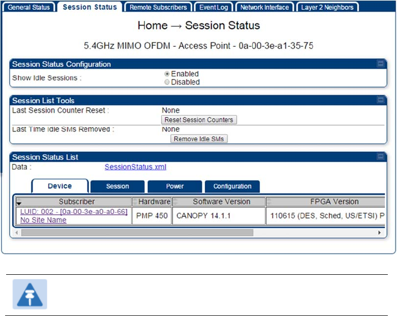
Procedure 15
Viewing the AP Session Status page
1
On the AP web management GUI, navigate to
Home
,
Session Status
:
Figure 127
Session Status tab of AP
Note
Session status page for BHM is same as AP.
2
Verify that for each SM (or BHS) MAC address (printed on the SM/BHS housing) the
AP/BHM has established a registered session by verifying the “State” status of each entry.
The Session Status page of the AP/BHM is explained in Table 102.
Chapter 7: Configuration Quick link setup
Page 7-22
Table 102
Session Status Attributes – AP
Attribute Meaning
Show Idle Sessions Idle subscribers may be included or removed from the session status display
by enabling or disabling, respectively, the
Show Idle Sessions
parameter.
Enabling or disabling this parameter only affects the GUI display of
subscribers, not the registration status.
Last Session Counter
Reset
This field displays date and time stamp of last session counter reset.
Last Time Idle SMs
Removed
This field displays date and time stamp of last Idle SMs Removed. On click of
“Remove Idle SMs” button, all the SMs which are in Idle state are flushed out.
Data See Exporting Session Status page of AP/BHM on page 7-209
Device tab See Device tab on page 9-20
Session tab See Session tab on page 9-21
Power tab See Power tab on page 9-23
Configuration tab See
Configuration tab on page 9-25

Chapter 7: Configuration Configuring IP and Ethernet interfaces
Page 7-23
Configuring IP and Ethernet interfaces
This task consists of the following sections:
Configuring the IP interface on page 7-23
Auxiliary port on page 7-26
NAT, DHCP Server, DHCP Client and DMZ on page 7-27
IP interface with NAT disabled on page 7-32
IP interface with NAT enabled on page
NAT tab with NAT disabled on page 7-35
NAT tab with NAT enabled on page 7-37
NAT DNS Considerations on page 7-42
DHCP – BHS on page 7-43
VLAN configuration for PMP on page 7-43
VLAN page of AP on page 7-46
VLAN page of SM on page 7-49
VLAN Membership tab of SM on page 7-53
VLAN configuration for PTP on page 7-53
NAT Port Mapping tab - SM on page 7-42
Chapter 7: Configuration Configuring IP and Ethernet interfaces
Page 7-24
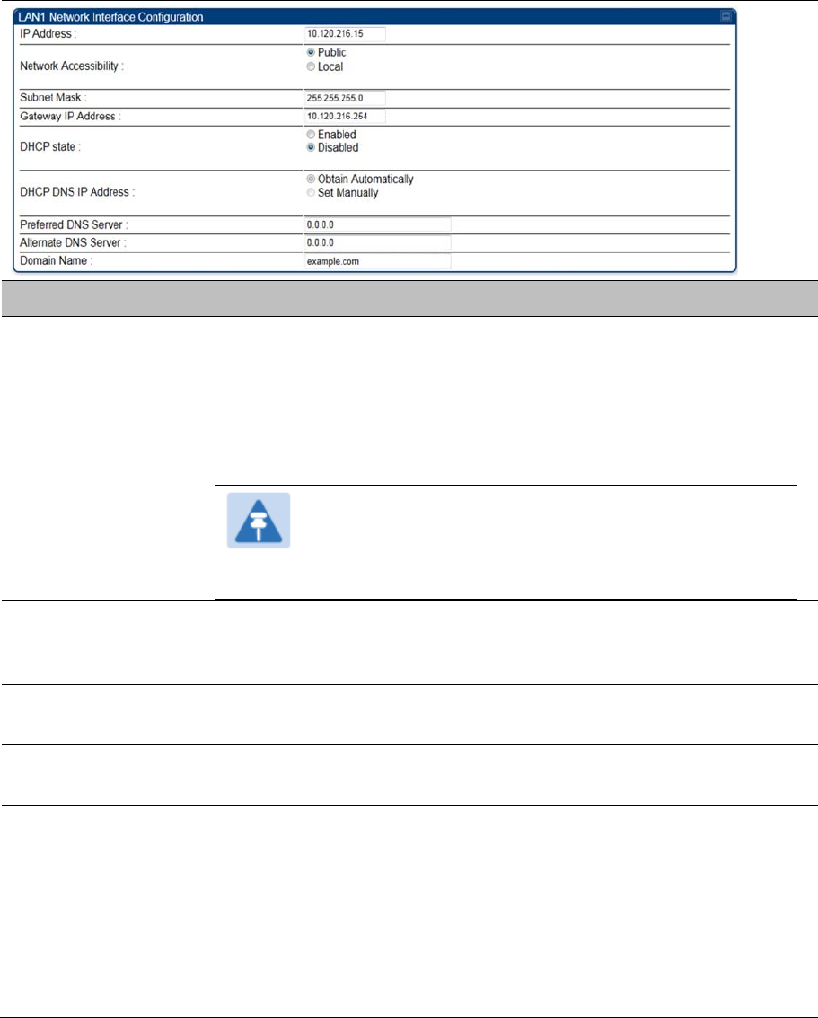
Configuring the IP interface
The IP interface allows users to connect to the 450 Platform Family web interface, either from a locally
connected computer or from a management network.
Applicable products PMP : AP SM PTP: BHM BMS
To configure the IP interface, follow these instructions:
Procedure 16 Configuring the AP/BHM IP interface
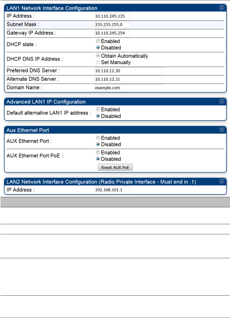
1 Select menu option Configuration > IP. The LAN configuration page is displayed:
2 Update IP Address, Subnet Mask and Gateway IP Address to meet network requirements (as
specified by the network administrator).
3 Review the other IP interface attributes and update them, if necessary (see Table 103 IP
interface attributes).
4 Click Save. “Reboot Required” message is displayed:
5 Click Reboot.
The IP page of AP/SM/BHM/BHS is explained in Table 103.
Chapter 7: Configuration Configuring IP and Ethernet interfaces
Page 7-25
Table 103 IP interface attributes
Attribute Meaning
IP Address Internet Protocol (IP) address. This address is used by family of Internet
protocols to uniquely identify this unit on a network.
Subnet Mask Defines the address range of the connected IP network.
Gateway IP Address The IP address of a computer on the current network that acts as a gateway.
A gateway acts as an entrance and exit to packets from and to other
networks.
DHCP state If Enabled is selected, the DHCP server automatically assigns the IP
configuration (IP address, subnet mask, and gateway IP address) and the
values of those individual parameters (above) are not used. The setting of this
DHCP state parameter is also viewable (read only), in the Network Interface
tab of the Home page.
DNS IP Address Canopy devices allow for configuration of a preferred and alternate DNS
server IP address either automatically or manually. Devices must set DNS
server IP address manually when DHCP is disabled for the management

Chapter 7: Configuration Configuring IP and Ethernet interfaces
Page 7-26
interface of the device. DNS servers may be configured automatically from
the DHCP response when DHCP is enabled for the management interface of
the device. Optionally devices may be configured to set the DNS server IP
address manually when DHCP is enabled for the management interface. The
default DNS IP addresses are 0.0.0.0 when configured manually.
Preferred DNS Server The first address used for DNS resolution.
Alternate DNS Server If the Preferred DNS server cannot be reached, the Alternate DNS Server is
used.
Domain Name The operator’s management domain name may be configured for DNS. The
domain name configuration can be used for configuration of the servers in the
operator’s network. The default domain name is example.com, and is only
used if configured as such.
Advanced LAN1 IP
Configuration –
Default alternate
LAN1 IP address
Hardcoded default alternate IP address (169.254.1.1) that is available only
when connected to the Ethernet port. When enabled, user can configure a
second IP address for the bridge which is other than the hardcoded IP
address (169.254.1.1).
AUX Ethernet Port –
AUX Ethernet Port
Enabled: Data is enabled for Auxiliary port
Disabled: Data is disabled for Auxiliary port
AUX Ethernet Port –
AUX Ethernet Port
PoE
Enabled: PoE out is enable for Auxiliary port
Disabled: PoE out is disabled for Auxiliary port
LAN2 Network
Interface
Configuration (Radio
Private Interface) – IP
Address
It is recommended not to change this parameter from the default AP/BHM
private IP address of 192.168.101.1. A /24 CIDR subnet is used to
communicate with each of the SMs/BHS that are registered. The AP/BHM
uses a combination of the private IP and the LUID (logical unit ID) of the
SM/BHS.
It is only displayed for AP and BHM.
Table 104 SM/BHS private IP and LUID
SM/BHS LUID Private IP
First SM/BHS registered 2 192.168.101.2
Second SM/BHS registered 3 192.168.101.3

Chapter 7: Configuration Configuring IP and Ethernet interfaces
Page 7-27
Auxiliary port
An additional Ethernet port labeled “Aux” for Auxiliary port is implemented for downstream traffic. This
feature is supported only for PTP/PMP 450i ODUs.
To enable the Aux port, follow these instructions:
Procedure 17 Enabling Aux port interface
1 Select menu option Configuration > IP > Aux Network Interface tab.:
2 Click Enable button of Aux Ethernet Port parameter to enable Aux Ethernet port
3 Click Enable button of Aux Ethernet Port PoE parameter to enable Aux port PoE out.
4 Click Save. “Reboot Required” message is displayed.
5 Click Reboot.
Table 105 Aux port attributes
Attribute Meaning
Aux Ethernet Port Enabled: Data is enabled for Auxiliary port
Disabled: Data is disabled for Auxiliary port
Aux Ethernet Port PoE Enabled: PoE out is enable for Auxiliary port
Disabled: PoE out is disabled for Auxiliary port
By disabling this feature, the data at the Auxiliary port will be disabled.

Chapter 7: Configuration Configuring IP and Ethernet interfaces
Page 7-28
NAT, DHCP Server, DHCP Client and DMZ
Applicable products PMP : SM
The system provides NAT (Network Address Translation) for SMs in the following combinations of NAT
and DHCP (Dynamic Host Configuration Protocol):
NAT Disabled
NAT with DHCP Client (DHCP selected as the Connection Type of the WAN interface) and DHCP
Server
NAT with DHCP Client(DHCP selected as the Connection Type of the WAN interface)
NAT with DHCP Server
NAT without DHCP
NAT
NAT isolates devices connected to the Ethernet or wired side of a SM from being seen directly from the
wireless side of the SM. With NAT enabled, the SM has an IP address for transport traffic (separate from
its address for management), terminates transport traffic and allows you to assign a range of IP
addresses to devices that are connected to the Ethernet or wired side of the SM.
In the Cambium system, NAT supports many protocols, including HTTP, ICMP (Internet Control Message
Protocols), and FTP (File Transfer Protocol). For virtual private network (VPN) implementation, L2TP over
IPSec (Level 2 Tunneling Protocol over IP Security) and PPTP (Point to Point Tunneling Protocol) are
supported.
Note
When NAT is enabled, a reduction in throughput is introduced in the system (due to
processing overhead).
DHCP
DHCP enables a device to be assigned a new IP address and TCP/IP parameters, including a default
gateway, whenever the device reboots. Thus DHCP reduces configuration time, conserves IP addresses,
and allows modules to be moved to a different network within the Cambium system.
In conjunction with the NAT features, each SM provides the following:
A DHCP server that assigns IP addresses to computers connected to the SM by Ethernet protocol.
A DHCP client that receives an IP address for the SM from a network DHCP server.
DMZ
In conjunction with the NAT features, a DMZ (Demilitarized Zone) allows the allotment of one IP address
behind the SM for a device to logically exist outside the firewall and receive network traffic. The first three
octets of this IP address must be identical to the first three octets of the NAT private IP address.
A DHCP server that assigns IP addresses to computers connected to the SM by Ethernet protocol.
A DHCP client that receives an IP address for the SM from a network DHCP server.
Chapter 7: Configuration Configuring IP and Ethernet interfaces
Page 7-29
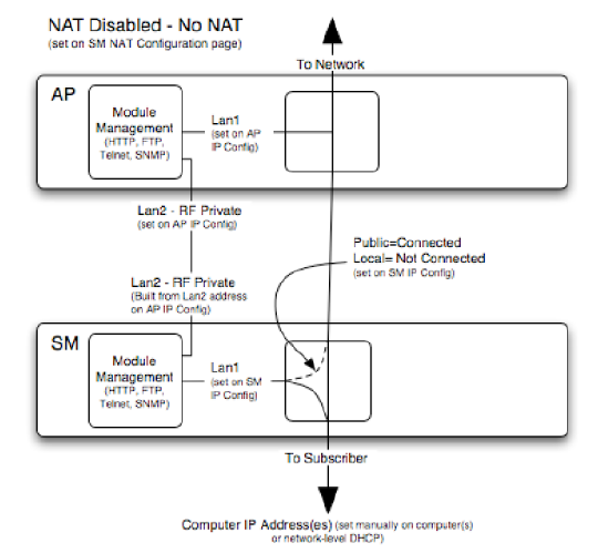
NAT Disabled
The NAT Disabled implementation is illustrated in Figure 128.
Figure 128 NAT disabled implementation
NAT with DHCP Client and DHCP Server
The NAT with DHCP Client and DHCP server is illustrated in Figure 129.
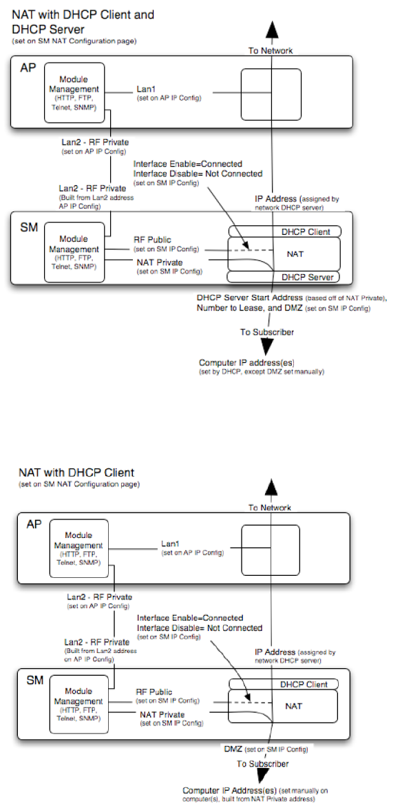
Chapter 7: Configuration Configuring IP and Ethernet interfaces
Page 7-30
Figure 129 NAT with DHCP client and DHCP server implementation
NAT with DHCP Client
Figure 130 NAT with DHCP client implementation
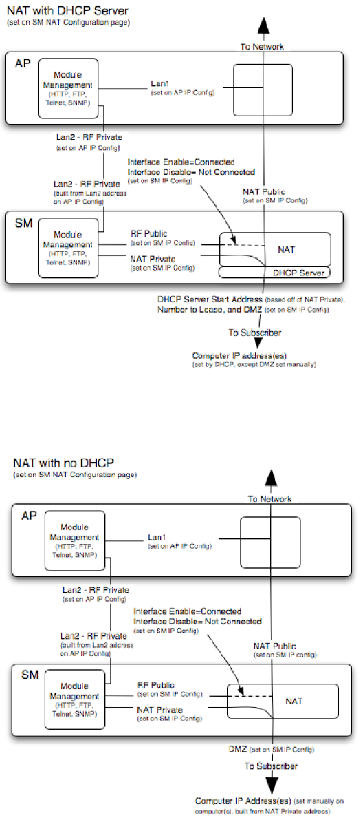
Chapter 7: Configuration Configuring IP and Ethernet interfaces
Page 7-31
NAT with DHCP Server
Figure 131 NAT with DHCP server implementation
NAT without DHCP
Figure 132 NAT without DHCP implementation
Chapter 7: Configuration Configuring IP and Ethernet interfaces
Page 7-32
NAT and VPNs
VPN technology provides the benefits of a private network during communication over a public network.
One typical use of a VPN is to connect employees remotely (who are at home or in a different city), with
their corporate network through a public Internet. Any of several VPN implementation schemes is
possible. By design, NAT translates or changes addresses, and thus interferes with a VPN that is not
specifically supported by a given NAT implementation.
With NAT enabled, SM supports L2TP over IPSec (Level 2 Tunneling Protocol over IP Security) VPNs
and PPTP (Point to Point Tunneling Protocol) VPNs. With NAT disabled, SM supports all types of VPNs.
Chapter 7: Configuration Configuring IP and Ethernet interfaces
Page 7-33
IP interface with NAT disabled - SM
The IP page of SM with NAT disabled is explained in Table 106.
Table 106
IP attributes - SM with NAT disabled
Attribute Meaning
IP Address
Enter the non-routable IP address to associate with the Ethernet connection
on this SM. (The default IP address from the factory is 169.254.1.1.) If you
forget this parameter, you must both:
physically access the module.
use recovery mode to access the module configuration parameters at
169.254.1.1. See Radio recovery mode on page 1-26
Note
Note or print the IP settings from this page. Ensure that you
can readily associate these IP settings both with the module
and with the other data that you store about the module.
Network Accessibility Specify whether the IP address of the SM must be visible to only a device
connected to the SM by Ethernet (
Local
) or be visible to the AP/BHM as well
(
Public
).
Subnet Mask Enter an appropriate subnet mask for the SM to communicate on the network.
The default subnet mask is 255.255.0.0.
Gateway IP Address Enter the appropriate gateway for the SM to communicate with the network.
The default gateway is 169.254.0.0.
DHCP state
If you select
Enabled
, the DHCP server automatically assigns the IP
configuration (IP address, subnet mask, and gateway IP address) and the
values of those individual parameters (above) are not used. The setting of this
DHCP state parameter is also viewable, but not settable, in the Network
Interface tab of the Home page.
In this tab, DHCP State is settable only if the
Network Accessibility
parameter in the IP tab is set to
Public
. This parameter is also settable in the
NAT tab of the Configuration web page, but only when NAT is enabled.

Chapter 7: Configuration Configuring IP and Ethernet interfaces
Page 7-34
If the DHCP state parameter is set to Enabled in the Configuration > IP
sub-menu of the SM/BHS, do not check the BootpClient option for Packet
Filter Types in its Protocol Filtering tab, because doing so can block the
DHCP request. (Filters apply to all packets that leave the SM via its RF
interface, including those that the SM itself generates.) If you want to keep
DHCP enabled and avoid the blocking scenario, select the Bootp Server
option instead. This will result in responses being appropriately filtered and
discarded.
DHCP DNS IP
Address
Canopy devices allow for configuration of a preferred and alternate DNS
server IP address either automatically or manually. Devices must set DNS
server IP address manually when DHCP is disabled for the management
interface of the device. DNS servers may be configured automatically from
the DHCP response when DHCP is enabled for the management interface of
the device. Optionally devices may be configured to set the DNS server IP
address manually when DHCP is enabled for the management interface. The
default DNS IP addresses are 0.0.0.0 when configured manually.
Preferred DNS Server The first DNS server used for DNS resolution.
Alternate DNS Server The second DNS server used for DNS resolution.
Domain Name The operator’s management domain name may be configured for DNS. The
domain name configuration can be used for configuration of the servers in the
operator’s network. The default domain name is example.com, and is only
used if configured as such.
Chapter 7: Configuration Configuring IP and Ethernet interfaces
Page 7-35
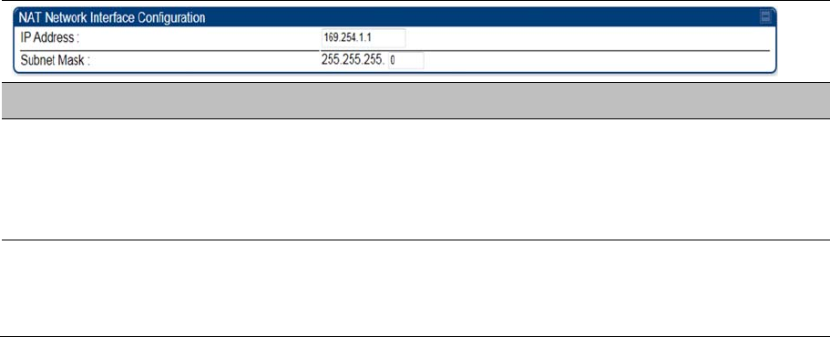
IP interface with NAT enabled - SM
The IP page of SM with NAT enabled is explained in Table 107.
Table 107
IP attributes - SM with NAT enabled
Attribute Meaning
IP Address
Assign an IP address for SM/BHS management through Ethernet access to
the SM/BHS. Set only the first three bytes. The last byte is permanently set to
1. This address becomes the base for the range of DHCP-assigned
addresses.
Subnet Mask
Assign a subnet mask of 255.255.255.0 or a more restrictive subnet mask.
Set only the last byte of this subnet mask. Each of the first three bytes is
permanently set to 255.
Chapter 7: Configuration Configuring IP and Ethernet interfaces
Page 7-36
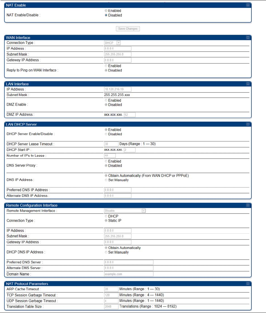
NAT tab with NAT disabled - SM
The NAT tab of SM with NAT disabled is explained in Table 108.
Table 108
NAT attributes - SM with NAT disabled

Chapter 7: Configuration Configuring IP and Ethernet interfaces
Page 7-37
Attribute Meaning
NAT Enable/Disable This parameter enables or disables the Network Address Translation (NAT)
feature for the SM. NAT isolates devices connected to the Ethernet or wired
side of a SM from being seen directly from the wireless side of the SM. With
NAT enabled, the SM has an IP address for transport traffic separate from its
address for management, terminates transport traffic, and allows you to
assign a range of IP addresses to devices that are connected to the Ethernet
or wired side of the SM.
When NAT is enabled, VLANs are not supported on the wired side of that SM.
You can enable NAT in SMs within a sector where VLAN is enabled in the
AP/BHM, but this may constrain network design.
IP Address This field displays the IP address for the SM. DHCP Server will not
automatically assign this address when NAT is disabled.
Subnet Mask This field displays the subnet mask for the SM. DHCP Server will not
automatically assign this address when NAT is disabled.
Gateway IP Address This field displays the gateway IP address for the SM. DHCP Server will not
automatically assign this address when NAT is disabled.
ARP Cache Timeout If a router upstream has an ARP cache of longer duration (as some use 30
minutes), enter a value of longer duration than the router ARP cache. The
default value of this field is 20 minutes.
TCP Session Garbage
Timeout
Where a large network exists behind the SM, you can set this parameter to
lower than the default value of 120 minutes. This action makes additional
resources available for greater traffic than the default value accommodates.
UDP Session
Garbage Timeout
You may adjust this parameter in the range of 1 to 1440 minutes, based on
network performance. The default value of this parameter is 4 minutes.
Translation Table Size Total number of minutes that have elapsed since the last packet transfer
between the connected device and the SM/BHS.
Note
When NAT is disabled, the following parameters are not required to be configurable:
WAN Inter face > Connection Type, IP Address, Subnet Mask, Gateway IP address
LAN Interface > IP Address
LAN DHCP Server > DHCP Server Enable/Disable, DHCP Server Lease Timeout, Number
of IP’s to Lease, DNS Server Proxy, DNS IP Address, Preferred DNS IP address, Alternate
DNS IP address
Remote Management Interface > Remote Management Interface, IP address, Subnet
Mask, DHCP DNS IP Address, Preferred DNS Server, Alternate DNS Server, Domain Name
NAT Protocol Parameters > ARP Cache Timeout, TCP Session Garbage Timeout, UDP
Session Garbage Timeout, Translation Table Size
Chapter 7: Configuration Configuring IP and Ethernet interfaces
Page 7-38
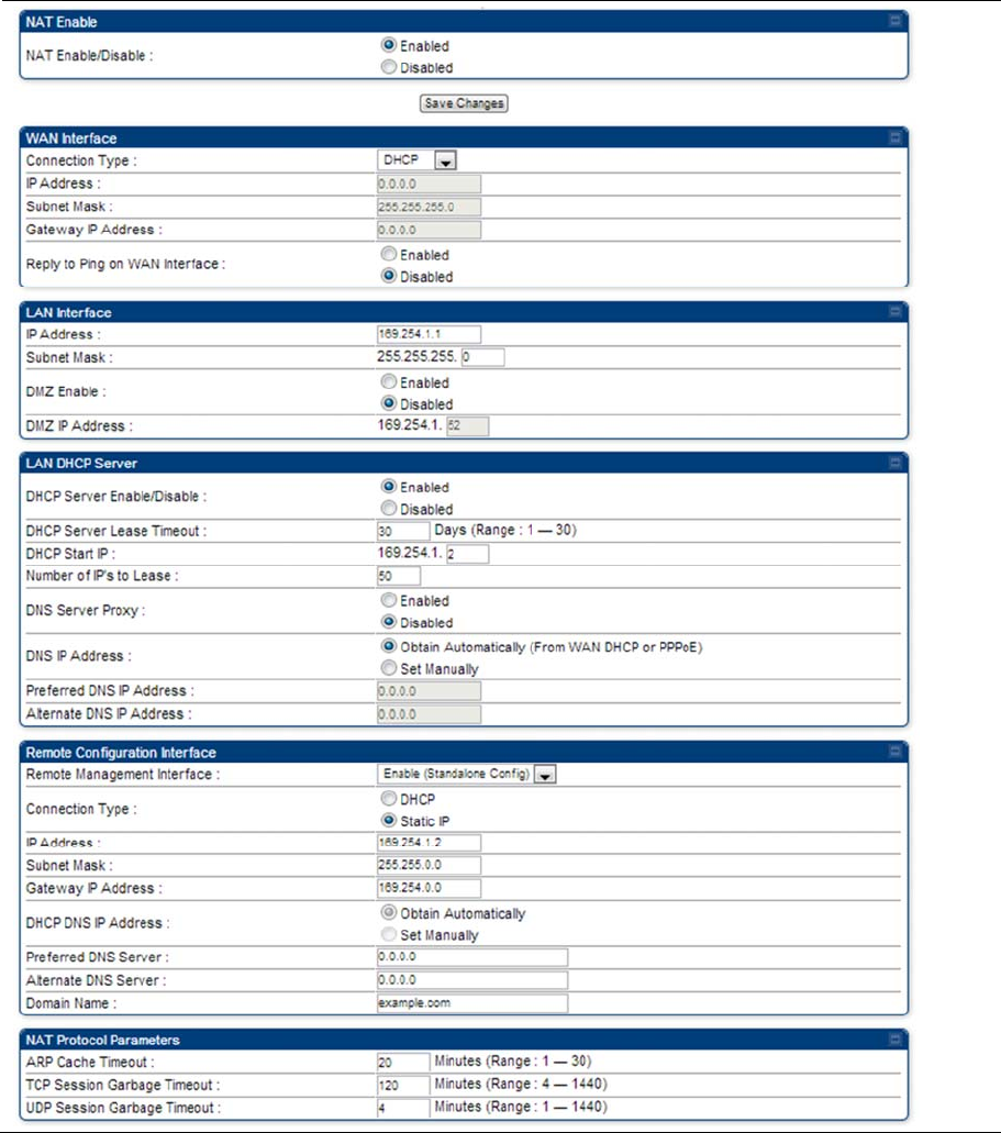
NAT tab with NAT enabled - SM
The NAT tab of SM with NAT enabled is explained in Table 109.
Table 109
NAT attributes - SM with NAT enabled

Chapter 7: Configuration Configuring IP and Ethernet interfaces
Page 7-39
Attribute Meaning
NAT Enable/Disable This parameter enables or disabled the Network Address Translation (NAT)
feature for the SM. NAT isolates devices connected to the Ethernet or wired
side of a SM from being seen directly from the wireless side of the SM. With
NAT enabled, the SM has an IP address for transport traffic separate from its
address for management, terminates transport traffic, and allows you to
assign a range of IP addresses to devices that are connected to the Ethernet
or wired side of the SM.
When NAT is enabled, VLANs are not supported on the wired side of that SM.
You can enable NAT in SMs within a sector where VLAN is enabled in the
AP, but this may constrain network design.
WAN Interface The WAN interface is the RF-side address for transport traffic.
Connection Type
This parameter may be set to
Static IP—when this is the selection, all three parameters (IP Address,
Subnet Mask, and Gateway IP Address) must be properly populated.
DHCP—when this is the selection, the information from the DHCP server
configures the interface.
PPPoE—when this is the selection, the information from the PPPoE server
configures the interface.
Subnet Mask If Static IP is set as the Connection Type of the WAN interface, then this
parameter configures the subnet mask of the SM for RF transport traffic.
Gateway IP Address If Static IP is set as the Connection Type of the WAN interface, then this
parameter configures the gateway IP address for the SM for RF transport
traffic.
Reply to Ping on WAN
Interface
By default, the radio interface does not respond to pings. If you use a
management system (such as WM) that will occasionally ping the SM, set this
parameter to Enabled.
LAN Interface The LAN interface is both the management access through the Ethernet port
and the Ethernet-side address for transport traffic. When NAT is enabled, this
interface is redundantly shown as the NAT Network Interface Configuration
on the IP tab of the Configuration web page in the SM.
IP Address Assign an IP address for SM/BHS management through Ethernet access to
the SM. This address becomes the base for the range of DHCP-assigned
addresses.
Subnet Mask Assign a subnet mask of 255.255.255.0 or a more restrictive subnet mask.
Set only the last byte of this subnet mask. Each of the first three bytes is
permanently set to 255.
DMZ Enable Either enable or disable DMZ for this SM/BHS.

Chapter 7: Configuration Configuring IP and Ethernet interfaces
Page 7-40
DMZ IP Address If you enable DMZ in the parameter above, set the last byte of the DMZ host
IP address to use for this SM when DMZ is enabled. Only one such address
is allowed. The first three bytes are identical to those of the NAT private IP
address. Ensure that the device that receives network traffic behind this SM is
assigned this address. The system provides a warning if you enter an
address within the range that DHCP can assign.
DHCP Server This is the server (in the SM) that provides an IP address to the device
connected to the Ethernet port of the SM.
DHCP Server
Enable/Disable
Select either Enabled or Disabled.
Enable to:
Allow this SM to assign IP addresses, subnet masks, and gateway IP
addresses to attached devices.
Assign a start address for DHCP.
Designate how many IP addresses may be temporarily used (leased).
Disable to:
Restrict SM/BHS from assigning addresses to attached devices.
DHCP Server Lease
Timeout
Based on network performance, enter the number of days between when the
DHCP server assigns an IP address and when that address expires. The
range of values for this parameter is 1 to 30 days. The default value is 30
days.
DHCP Start IP If you enable DHCP Server below, set the last byte of the starting IP address
that the DHCP server assigns. The first three bytes are identical to those of
the NAT private IP address.
Number of IPs to
Lease
Enter how many IP addresses the DHCP server is allowed to assign. The
default value is 50 addresses.
DNS Server Proxy This parameter enables or disables advertisement of the SM/BHS as the DNS
server. On initial boot up of a SM with the NAT WAN interface configured as
DHCP or PPPoE, the SM module will not have DNS information immediately.
With DNS Server Proxy disabled, the clients will renew their lease about
every minute until the SM has the DNS information to give out. At this point
the SM will go to the full configured lease time period which is 30 days by
default. With DNS Server Proxy enabled, the SM will give out full term leases
with its NAT LAN IP as the DNS server.
DNS IP Address
Select either:
Obtain Automatically to allow the system to set the IP address of the DNS
server
or
Set Manually to enable yourself to set both a preferred and an alternate DNS
IP address.
Preferred DNS IP
Address
Enter the preferred DNS IP address to use when the DNS IP Address
parameter is set to Set Manually.
Chapter 7: Configuration Configuring IP and Ethernet interfaces
Page 7-41
Alternate DNS IP
Address
Enter the DNS IP address to use when the DNS IP Address parameter is set
to Set Manually and no response is received from the preferred DNS IP
address.
Remote Management
Interface
To offer greater flexibility in IP address management, the NAT-enabled SM’s
configured WAN Interface IP address may now be used as the device
Remote Management Interface (unless the SM’s PPPoE client is set to
Enabled)
Disable: When this interface is set to “Disable”, the SM is not directly
accessible by IP address. Management access is only possible through either
the LAN (Ethernet) interface or a link from an AP web page into the WAN
(RF-side) interface.
Enable (Standalone Config): When this interface is set to “Enable
(Standalone Config)”, to manage the SM/BHS the device must be accessed
by the IP addressing information provided in the Remote Configuration
Interface section.
Note
When configuring PPPoE over the link, use this configuration
option (PPPoE traffic is routed via the IP addressing specified in
section Remote Configuration Interface).
Enable (Use WAN Interface): When this interface is set to “Enable (Use
WAN Interface)”, the Remote Configuration Interface information is greyed
out, and the SM is managed via the IP addressing specified in section WAN
Interface).
Note
When using this configuration, the ports defined in section
Configuration, Port Configuration are consumed by the device.
For example, if FTP Port is configured as 21 by the SM, an FTP
server situated below the SM must use a port other than 21. This
also applies to DMZ devices; any ports specified in section
Configuration, Port Configuration will not be translated through
the NAT, they is consumed by the device’s network stack for
management.
Connection Type
This parameter can be set to:
Static IP—when this is the selection, all three parameters (IP Address,
Subnet Mask, and Gateway IP Address) must be properly populated.
DHCP—when this is the selection, the information from the DHCP server
configures the interface.
IP Address
If Static IP is set as the Connection Type of the WAN interface, then this
parameter configures the IP address of the SM for RF management traffic.
Subnet Mask
If Static IP is set as the Connection Type of the WAN interface, then this
parameter configures the subnet mask of the SM for RF management traffic.

Chapter 7: Configuration Configuring IP and Ethernet interfaces
Page 7-42
Gateway IP Address
If Static IP is set as the Connection Type of the WAN interface, then this
parameter configures the gateway IP address for the SM for RF management
traffic.
Note or print the IP settings from this page. Ensure that you can readily
associate these IP settings both with the module and with the other data that
you store about the module.
DHCP DNS IP
Address
Select either:
Obtain Automatically to allow the system to set the IP address of the DNS
server.
or
Set Manually to enable yourself to set both a preferred and an alternate DNS
IP address.
Preferred DNS Server Enter the preferred DNS IP address to use when the DNS IP Address
parameter is set to Set Manually.
Alternate DNS Server Enter the DNS IP address to use when the DNS IP Address parameter is set
to Set Manually and no response is received from the preferred DNS IP
address.
Domain Name Domain Name to use for management DNS configuration. This domain name
may be concatenated to DNS names used configured for the remote
configuration interface.
ARP Cache Timeout If a router upstream has an ARP cache of longer duration (as some use 30
minutes), enter a value of longer duration than the router ARP cache. The
default value of this field is 20 (minutes).
TCP Session Garbage
Timeout
Where a large network exists behind the SM, you can set this parameter to
lower than the default value of 120 (minutes). This action makes additional
resources available for greater traffic than the default value accommodates.
UDP Session
Garbage Timeout
You may adjust this parameter in the range of 1 to 1440 minutes, based on
network performance. The default value of this parameter is 4 (minutes).
Chapter 7: Configuration Configuring IP and Ethernet interfaces
Page 7-43
NAT DNS Considerations - SM
SM DNS behavior is different depending on the accessibility of the SM. When NAT is enabled the DNS
configuration that is discussed in this document is tied to the RF Remote Configuration Interface, which
must be enabled to utilize DNS Client functionality. Note that the WAN DNS settings when NAT is
enabled are unchanged with the addition of the management DNS feature discussed in this document.
Table 110 SM DNS Options with NAT Enabled
NAT
Configuration
Management Interface
Accessibility
DHCP Status DNS Status
NAT Enabled
RF Remote
Management Interface
Disabled
N/A DNS Disabled
RF Remote
Management Interface
Enabled
DHCP Disabled DNS Static Configuration
DHCP Enabled DNS from DHCP or DNS
Static Configuration
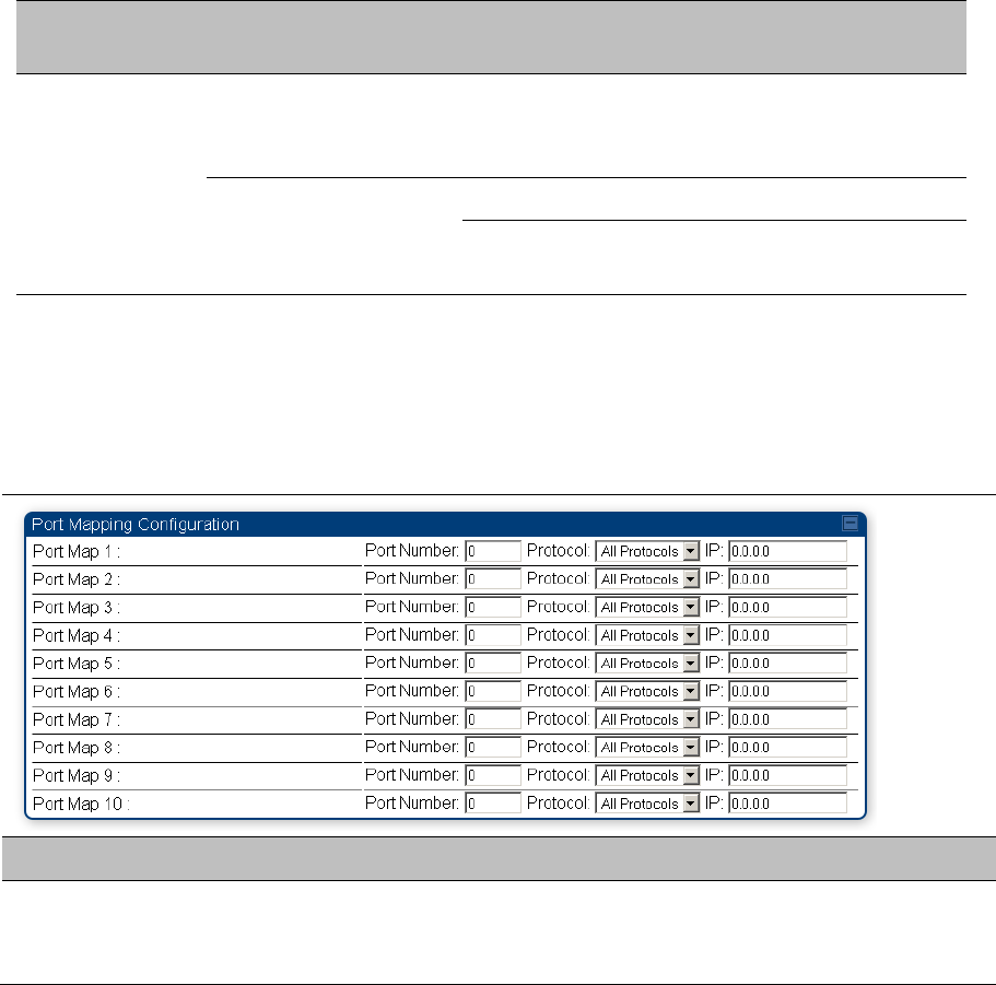
NAT Port Mapping tab - SM
The NAT Port Mapping tab of the SM is explained in Table 111.
Table 111 NAT Port Mapping attributes - SM
Attribute Meaning
Port Map 1 to 10 Separate parameters allow you to distinguish NAT ports from each other by
assigning a unique combination of port number, protocol for traffic through the
port, and IP address for access to the port

Chapter 7: Configuration Configuring IP and Ethernet interfaces
Page 7-44
DHCP – BHS
Applicable products PTP: BHM
DHCP enables a device to be assigned a new IP address and TCP/IP parameters, including a default
gateway, whenever the device reboots. Thus DHCP reduces configuration time, conserves IP addresses,
and allows modules to be moved to a different network within the Cambium system.
In conjunction with the NAT features, each BHS provides:
A DHCP server that assigns IP addresses to computers connected to the BHS by Ethernet protocol.
A DHCP client that receives an IP address for the BHS from a network DHCP server.
Reconnecting to the management PC
If the IP Address, Subnet Mask and Gateway IP Address of the unit have been updated to meet network
requirements, then reconfigure the local management PC to use an IP address that is valid for the
network. See Configuring the management PC on page 7-3.
Once the unit reboots, log in using the new IP address. See Logging into the web interface on page 7-5.
VLAN configuration for PMP
Applicable products PMP : AP SM
VLAN Remarking
VLAN Remarking feature allows the user to change the VLAN ID and priority of both upstream and
downstream packets at the Ethernet Interface. The remarking configuration is available for:
1. VLAN ID re-marking
2. 802.1p priority re-marking
Note
For Q-in-Q VLAN tagged frame, re-marking is performed on the outer tag.

Chapter 7: Configuration Configuring IP and Ethernet interfaces
Page 7-45
VLAN ID Remarking
SM supports the ability to re-mark the VLAN ID on both upstream and downstream VLAN frames at the
Ethernet interface. For instance, a configuration can be added to re-mark VLAN ID ‘x’ to VLAN ID ‘y’ as
shown in Table 112. AP does not support VLAN ID remarking.
Table 112 VLAN Remarking Example
VLAN frame direction Remarking
Upstream
SM receives VLAN ID ‘x’ frame at the Ethernet interface, checks the
configuration and re-marks to VLAN ID ‘y’. So VLAN ID ‘y’ frame comes
out of AP’s Ethernet interface. When SM re-marks, a dynamic entry in
VLAN membership table for ‘y’ is added to allow reception of VLAN ID
‘y’ downstream packet.
Downstream
AP receives VLAN ID ‘y’ frame at the Ethernet interface and sends to
SM. SM accepts the frame as it has an entry in the membership table
and re-marks to VLAN ID ‘x’. This reverse re- marking is necessary
because the downstream devices do not know of re-marking and are
expecting VLAN ‘x’ frames. This remarking is done just before sending
the packet out on Ethernet interface.
802.1P Remarking
AP/BHM and SM/BHS allow re-marking of 802.1p priority bits for the frames received at the Ethernet
interface. Priority bits are not re-marked for the packets sent out of Ethernet interface (reverse direction).
Configuration must be added at SM/BHS for upstream frames and at AP/BHM for downstream frames.
VLAN Priority Bits configuration
VLAN Priority Bits Configuration feature allows the user to configure the three 802.1p bits upon
assigning VLAN to an ingress packet. The priority bits configuration is available for:
Default Port VID
Provider VID
MAC Address mapped Port VID
Management VID
Default Port VID
This VID is used for untagged frames and will correspond to the Q-Tag for 802.1Q frames (if VLAN
Port Type is Q), or the C-Tag for 802.1ad frames (if the VLAN Port Type is QinQ).
The priority bits used in the Q-tag/C-tag are configurable.
The configuration can be:
Promote IPv4/IPv6 priority – The priority in the IP header is copied to the Q-tag/C-tag.
Chapter 7: Configuration Configuring IP and Ethernet interfaces
Page 7-46
Define priority – Specify the priority in the range of 0 to 7. This value is used as priority in the Q-
tag/C-tag.
MAC Address Mapped VID
If a packet arrives at the SM/BHS that is sourced from a device whose MAC address is in the table,
then the corresponding VID is used for that frame’s Q-tag (Q port) or C-tag (QinQ port). The priority bits
used in the Q-tag/C-tag are configurable similar to default port VID.
Provider VID
The provider VID is used for the S-tag. The priority bits used in the S-tag are configurable similar to
default port VID. Provider VID has an extra priority configuration:
Copy inner tag 802.1p priority – The priority in the C-tag is copied to the S-tag.
Management VID
This VID is used to communicate with AP/BHM and SM/BHS for management purposes. The priority
bits used in the Q-tag are configurable similar to default port VID.
Use AP’s Management VID for ICC connected SM
This feature allows the SM to use the AP’s management VLAN ID when the SM is registered to the AP
via ICC. This feature is useful for the customer who uses a different management VID for the SM and
AP and Zero Touch feature is enabled for configuration. This parameter may be accessed via the
Configuration > VLAN page on the AP’s web management interface.
Chapter 7: Configuration Configuring IP and Ethernet interfaces
Page 7-47
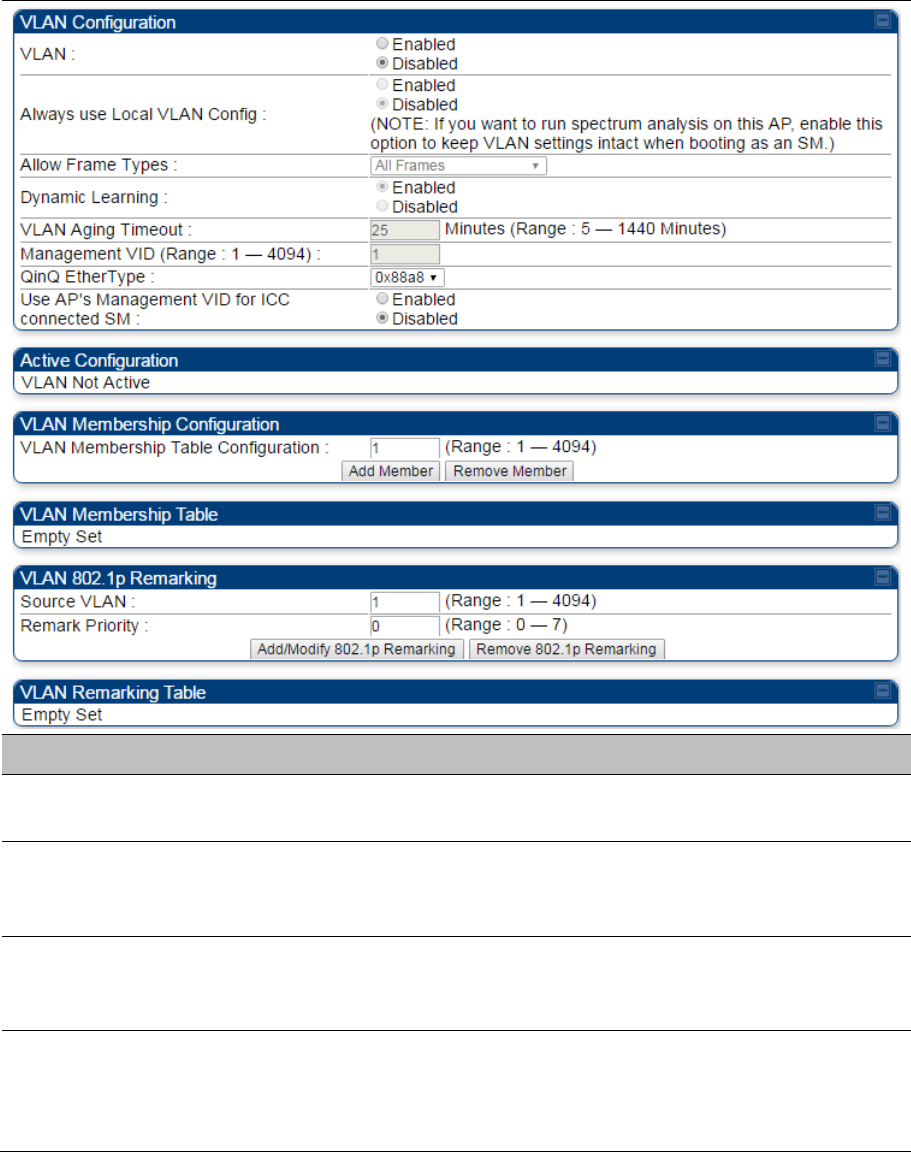
VLAN page of AP
The VLAN tab of the AP/BHM is explained in Table 113.
Table 113 AP/BHM VLAN tab attributes
Attribute Meaning
VLAN Specify whether VLAN functionality for the AP and all linked SMs must
(Enabled) or may not (Disabled) be allowed. The default value is Disabled.
Always use Local
VLAN Config
Enable this option before you reboot this AP as a SM to use it to perform
spectrum analysis. Once the spectrum analysis completes, disable this option
before you reboot the module as an AP,
Allow Frame Types Select the type of arriving frames that the AP must tag, using the VID that is
stored in the Untagged Ingress VID parameter. The default value is All
Frames.
Dynamic Learning Specify whether the AP must (Enabled) or not (Disabled) add the VLAN IDs
(VIDs) of upstream frames to the VID table. (The AP passes frames with VIDs
that are stored in the table both upstream and downstream.). The default
value is Enabled.

Chapter 7: Configuration Configuring IP and Ethernet interfaces
Page 7-48
VLAN Aging Timeout Specify how long the AP must keep dynamically learned VIDs. The range of
values is 5 to 1440 (minutes). The default value is 25 (minutes).
Note
VIDs that you enter for the Management VID and VLAN
Membership parameters do not time out.
Management VID Enter the VID that the operator wishes to use to communicate with the
module manager. The range of values is 1 to 4095. The default value is 1.
QinQ EtherType Modules can be configured with 802.1ad Q-in-Q DVLAN (Double-VLAN)
tagging which is a way for an operator to put an 802.1Q VLAN inside of an
802.1ad VLAN. A nested VLAN, which is the original 802.1Q tag and a new
second 802.1ad tag, allows for bridging of VLAN traffic across a network and
segregates the broadcast domains of 802.1Q VLANs. Q-in-Q can be used
with PPPoE and/or NAT.
The 802.1ad standard defines the S-VLAN as the Service Provider VLAN and
the C-VLAN as the customer VLAN. The radio software does 2 layer Q-in-Q
whereby the C-VLAN is the 802.1Q tag and the S-VLAN is the second layer Q
tag as shown below:
Table 114 Q-in-Q Ethernet frame
Ethernet
Header
S-VLAN EthType
0x88a8
C-VLAN EthType
0x8100
IP Data EthType
0x0800
The 802.1ad S-VLAN is the outer VLAN that is configurable on the
Configuration > VLAN web page of the AP. The Q-in-Q EtherType
parameter is configured with a default EtherType of 0x88a8 in addition to four
alternate EtherTypes that can be configured to aid in interoperability with
existing networks that use a different EtherType than the default.
The C-VLAN is the inner VLAN tag, which is the same as 802.1Q. As a top
level concept, this operates on the outermost tag at any given time, either
“pushing” a tag on or “popping” a tag off. This means packets will at most
transition from an 802.1Q frame to an 801.ad frame (with a tag “pushed” on)
or an untagged 802.1 frame (with the tag “popped” off. Similarly, for an
802.1ad frame, this can only transition from an 802.1ad frame to an 802.1Q
frame (with the tag “popped” off) since the radio software only supports 2
levels of tags
Use AP's
Management VID for
ICC connected SM
This field allows the SM to use the AP’s management VLAN ID when the SM
is registered to the AP via ICC.
VLAN Not Active When VLAN is enabled in the AP, the Active Configuration block provides the
following details as read-only information in this tab. In the Cambium fixed
wireless broadband IP network, each device of any type is automatically a
permanent member of VID 1. This facilitates deployment of devices that have
VLAN enabled with those that do not.

Chapter 7: Configuration Configuring IP and Ethernet interfaces
Page 7-49
VLAN Membership
Table Configuration
For each VLAN in which you want the AP to be a member, enter the VLAN ID
and then click the Add Member button. Similarly, for any VLAN in which you
want the AP to no longer be a member, enter the VLAN ID and then click the
Remove Member button.
VLAN Membership
table
This field lists the VLANs that an AP is a member of. As the user adds a
number between 1 and 4094, this number is populated here.
Source VLAN (Range:
1-4094)
Enter the VID for which the operator wishes to remark the 802.1p priority for
the downstream packets. The range of values is 1 to 4094. The default value
is 1.
Remark Priority
(Range 0-7)
This is the priority you can assign to the VLAN Tagged packet. Priority of 0 is
the highest.
VLAN Remarking
table
As the user enters a VLAN and a Remarking priority, this information is added
in this table.
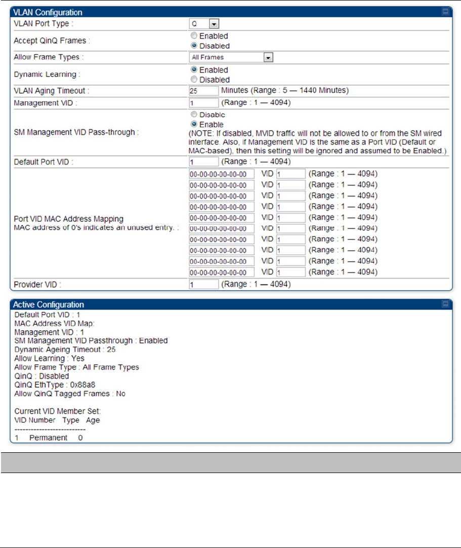
Chapter 7: Configuration Configuring IP and Ethernet interfaces
Page 7-50
VLAN page of SM
The
VLAN
tab of SM/BHS is explained in Table 115.
Table 115
SM VLAN attributes
Attribute Meaning
VLAN Port Type By default this is Q, indicating that it is to operate in the existing manner. The
other option is Q-in-Q, which indicates that it must be adding and removing
the S-Tag, and adding a C-Tag if necessary for untagged packets. The VLAN
Port type corresponds to the Ethernet port of the SM/BHS. Currently, the
internal management interfaces will always operate as Q ports.
Chapter 7: Configuration Configuring IP and Ethernet interfaces
Page 7-51
Accept QinQ Frames This option is valid for the Q-in-Q port so that the user may force blocking of
existing 802.1ad Q-in-Q frames. This way, only untagged or single tagged
packets will come in and out of the Ethernet interface. If a Q-in-Q frame is
about ingress or egress the Ethernet interface and this is disabled, it is
dropped and a filter entry will show up on the VLAN Statistics page as DVLAN
Egress or DVLAN Ingress.
Allow Frame Types Select the type of arriving frames that the SM must tag, using the VID that is
stored in the Untagged Ingress VID parameter. The default value is All
Frames.
Tagged Frames Only: The SM only tags incoming VLAN-tagged frames
Untagged Frames Only: The SM will only tag incoming untagged frames
Dynamic Learning Specify whether the SM must (Enable) or not (Disable) add the VIDs of
upstream frames (that enter the SM through the wired Ethernet interface) to
the VID table. The default value is Enable.
VLAN Aging Timeout Specify how long the SM/BHS must keep dynamically learned VIDs. The
range of values is 5 to 1440 (minutes). The default value is 25 (minutes).
Note
VIDs that you enter for the Untagged Ingress VID and
Management VID parameters do not time out.
Management VID Enter the VID that the SM/BHS must share with the AP/BHM. The range of
values is 1 to 4095. The default value is 1.
SM Management VID
Pass-through
Specify whether to allow the SM/BHS (Enabled) or the AP/RADIUS
(Disabled) to control the VLAN settings of this SM. The default value is
Enabled.
When VLAN is enabled in the AP to whom this SM is registered, the Active
Configuration block provides the following details as read-only information in
this tab. In the Cambium fixed wireless broadband IP network, each device of
any type is automatically a permanent member of VID 1. This facilitates
deployment of devices that have VLAN enabled with those that do not.
If disabled, MVID traffic is not allowed to or from the SM wired interface. Also,
if Management VID is the same as a Port VID (Default or MAC-based), then
this setting is ignored and assumed to be Enabled.
Default Port VID This is the VID that is used for untagged frames and will correspond to the Q-
Tag for 802.1Q frames (if VLAN Port Type is Q), or the C-Tag for 802.1ad
frames (if the VLAN Port Type is Q-in- Q).

Chapter 7: Configuration Configuring IP and Ethernet interfaces
Page 7-52
Port VID MAC
Address Mapping
These parameters allow operators to place specific devices onto different
VLANs (802.1Q tag or 802.1ad C-tag) based on the source MAC address of
the packet. If the MAC address entry is 00-00-00-00-00-00 then that entry is
not used. If a packet arrives at the SM that is sourced from a device whose
MAC address is in the table, then the corresponding VID is used for that
frame’s Q-tag (Q port) or C-tag (Q-in-Q port). If there is no match, then the
Default Port VID is used. This table is also used in the downstream direction
for removal of the tag based on the destination MAC address so that an
untagged (for Q port) or Q-Tagged (for Q-in-Q port) frame is delivered to the
end device. You may use wildcards for the non-OUI (Organizationally
Unique Identifier) portion of the MAC address, which is the last 3 bytes.
MAC addresses contain 6 bytes, the first 3 of which are the OUI of the
vendor that manufactured the device and the last 3 are unique to that
vendor OUI. If you want to cover all devices from a known vendor’s OUI,
you have to specify 0xFF for the remaining 3 bytes. So, for example, if you
wanted all devices from a specific vendor with an OUI of 00-95-5b (which is
a Netgear OUI) to be on the same VID of 800, you have to specify an entry
with MAC address 00-95-5b-ff-ff-ff. Then, any device underneath of the SM
with MAC addresses starting with 00-95-5b is put on VLAN 800.
Provider VID The provider VID is used for the S-tag. It is only used if the Port Type is Q-
in-Q and will always be used for the S-tag. If an existing 802.1Q frame
arrives, the Provider VID is what is used for adding and removing of the
outer S-tag. If an untagged frame arrives to a Q-in-Q port, then the Provider
VID is the S-tag and the Default Port VID (or Port VID MAC Address
Mapping, if valid) is used for the C-tag.
Active Configuration,
Default Port VID
This is the value of the parameter of the same name, configured above.
Active Configuration,
MAC Address VID
Map
This is the listing of the MAC address VIDs configured in Port VID MAC
Address Mapping.
Active Configuration,
Management VID
This is the value of the parameter of the same name, configured above.
Active Configuration,
SM Management VID
Pass-Through
This is the value of the parameter of the same name, configured above.
Active Configuration,
Dynamic Aging
Timeout
This is the value of the VLAN Aging Timeout parameter configured above.
Active Configuration,
Allow Learning
Yes is displayed if the value of the Dynamic Learning parameter above is
Enabled. No is displayed if the value of Dynamic Learning is Disabled.
Active Configuration,
Allow Frame Type
This displays the selection that was made from the drop-down list at the
Allow Frame Types parameter above.
Chapter 7: Configuration Configuring IP and Ethernet interfaces
Page 7-53
Active Configuration,
QinQ
This is set to Enabled if VLAN Port Type is set to QinQ, and is set to
Disabled if VLAN Port Type is set to Q.
Active Configuration,
QinQ EthType
This is the value of the QinQ EtherType configured in the AP.
Active Configuration,
Allow QinQ Tagged
Frames
This is the value of Accept QinQ Frames, configured above.
Active Configuration,
Current VID Member
Set, VID Number
This column lists the ID numbers of the VLANs in which this module is a
member, whether through assignment or through dynamic learning.
Active Configuration,
Current VID Member
Set, Type
For each VID number in the first column, the entry in this column correlates
the way in which the module became and continues to be a member:
Permanent—This indicates that the module was assigned the VID number
through direct configuration by the operator.
Dynamic—This indicates that the module adopted the VID number through
enabled dynamic learning, when a tagged packet from a SM behind it in the
network or from a customer equipment that is behind the SM in this case, was
read.
Active Configuration,
Current VID Member
Set, Age
For each VID number in the first column of the table, the entry in this column
reflects whether or when the VID number will time out:
Permanent type - Number never times out and this is indicated by the digit 0.
Dynamic type - Age reflects what is configured in the VLAN Aging Timeout
parameter in the Configuration => VLAN tab of the AP or reflects a fewer
number of minutes that represents the difference between what was
configured and what has elapsed since the VID was learned. Each minute,
the Age decreases by one until, at zero, the AP deletes the learned VID, but
can it again from packets sent by elements that are beneath it in the network.
Note
Values in this Active Configuration block can differ from
attempted values in configurations:
The AP can override the value that the SM has configured for SM
Management VID Pass-Through.
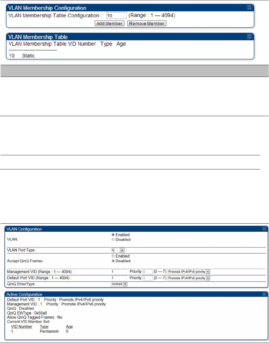
Chapter 7: Configuration Configuring IP and Ethernet interfaces
Page 7-54
VLAN Membership tab of SM
The
Configuration > VLAN >
VLAN Membership
tab is explained in Table 116.
Table 116
SM VLAN Membership attributes
Attribute Meaning
VLAN Membership
Table Configuration
For each VLAN in which you want the AP to be a member, enter the VLAN ID
and then click the
Add Member
button. Similarly, for any VLAN in which you
want the AP to no longer be a member, enter the VLAN ID and then click the
Remove Member
button.
VLAN configuration for PTP
Applicable products
PTP:
BHM
BMS
VLAN page of BHM
The VLAN tab of BHS is explained in Table 117.
Table 117
BHM VLAN page attributs

Chapter 7: Configuration Configuring IP and Ethernet interfaces
Page 7-55
Attribute Meaning
VLAN Specify whether VLAN functionality for the BHM and all linked BHS must be
(Enabled) or may not (Disabled) be allowed. The default value is Disabled.
VLAN Port Type By default this is Q, indicating that it is to operate in the existing manner. The
other option is Q-in-Q, which indicates that it must be adding and removing
the S-Tag, and adding a C-Tag if necessary for untagged packets. The VLAN
Port type corresponds to the Ethernet port of the BHS. Currently, the internal
management interfaces will always operate as Q ports.
Accept QinQ Frames This option is valid for the Q-in-Q port so that the user may force blocking of
existing 802.1ad Q-in-Q frames. This way, only untagged or single tagged
packets will come in and out of the Ethernet interface. If a Q-in-Q frame is
about ingress or egress the Ethernet interface and this is disabled, it is
dropped and a filter entry will show up on the VLAN Statistics page as DVLAN
Egress or DVLAN Ingress.
Management VID
(Range 1-4094)
Enter the VID that the BHS must share with the BHM. The range of values is
1 to 4095. The default value is 1.
Default Port VID
(Range 1-4094)
This is the VID that is used for untagged frames and corresponds to the Q-Tag
for 802.1Q frames (if VLAN Port Type is Q), or the C-Tag for 802.1ad frames
(if the VLAN Port Type is Q-in- Q).
QinQ Ether Type Modules can be configured with 802.1ad Q-in-Q DVLAN (Double-VLAN)
tagging which is a way for an operator to put an 802.1Q VLAN inside of an
802.1ad VLAN. A nested VLAN, which is the original 802.1Q tag and a new
second 802.1ad tag, allows for bridging of VLAN traffic across a network and
segregates the broadcast domains of 802.1Q VLANs. Q-in-Q can be used
with PPPoE and/or NAT.
The 802.1ad standard defines the S-VLAN as the Service Provider VLAN and
the C-VLAN as the customer VLAN. The radio software does 2 layer Q-in-Q
whereby the C-VLAN is the 802.1Q tag and the S-VLAN is the second layer Q
tag as shown below:
Ethernet
Header
S-VLAN EthType
0x88a8
C-VLAN
EthType 0x8100
IP Data EthType
0x0800
The 802.1ad S-VLAN is the outer VLAN that is configurable on the
Configuration > VLAN web page of the BHM. The Q-in-Q EtherType
parameter is configured with a default EtherType of 0x88a8 in addition to four
alternate EtherTypes that can be configured to aid in interoperability with
existing networks that use a different EtherType than the default.

Chapter 7: Configuration Configuring IP and Ethernet interfaces
Page 7-56
The C-VLAN is the inner VLAN tag, which is the same as 802.1Q. As a top
level concept, this operates on the outermost tag at any given time, either
“pushing” a tag on or “popping” a tag off. This means packets will at most
transition from an 802.1Q frame to an 801.ad frame (with a tag “pushed” on)
or an untagged 802.1 frame (with the tag “popped” off. Similarly, for an
802.1ad frame, this can only transition from an 802.1ad frame to an 802.1Q
frame (with the tag “popped” off) since the radio software only supports 2
levels of tags.
VLAN Not Active When VLAN is enabled in the BHM, the Active Configuration block provides
the following details as read-only information in this tab. In the Cambium fixed
wireless broadband IP network, each device of any type is automatically a
permanent member of VID 1. This facilitates deployment of devices that have
VLAN enabled with those that do not.
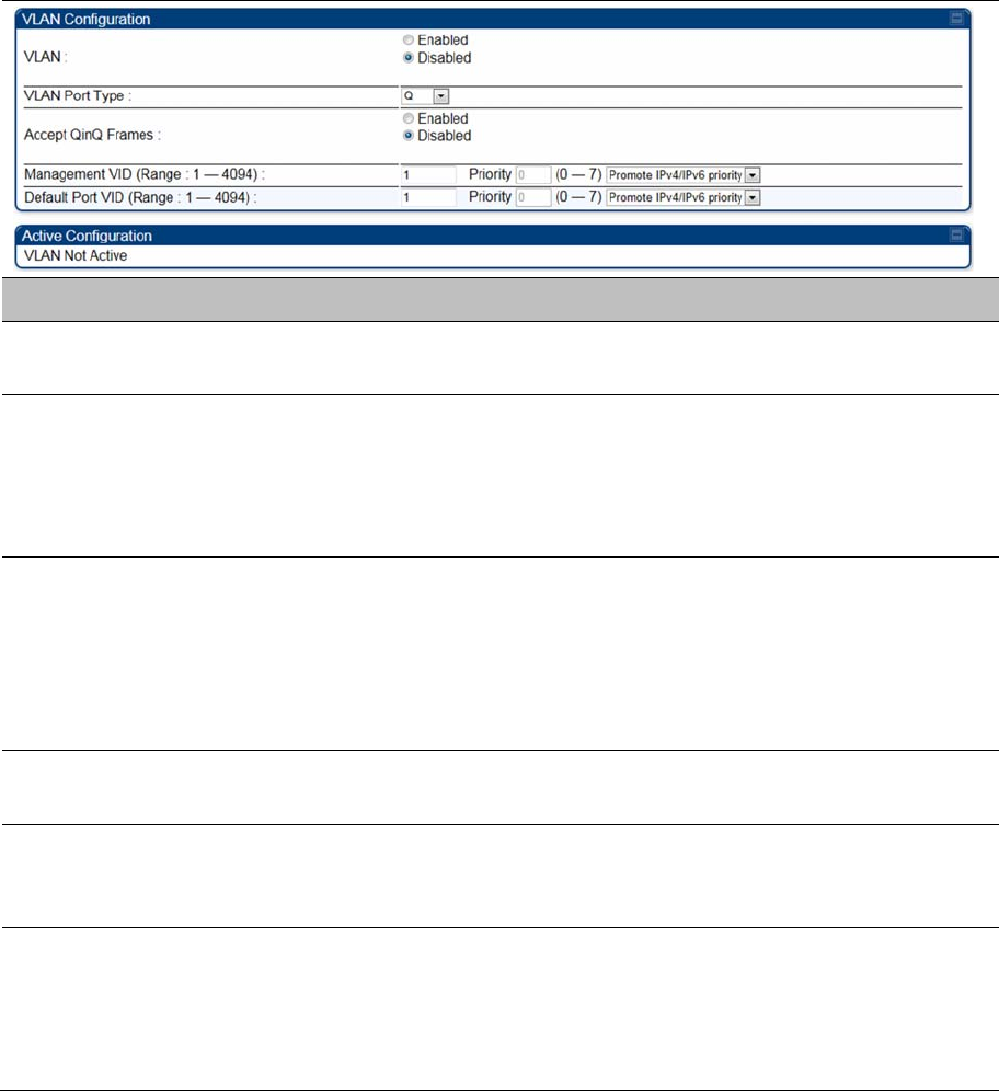
Chapter 7: Configuration Configuring IP and Ethernet interfaces
Page 7-57
VLAN page of BHS
The VLAN tab of BHS is explained in Table 118.
Table 118
BHS VLAN page attributes
Attribute Meaning
VLAN Specify whether VLAN functionality for the BHM and all linked BHS must be
(Enabled) or may not (Disabled) be allowed. The default value is Disabled.
VLAN Port Type By default this is Q, indicating that it is to operate in the existing manner. The
other option is Q-in-Q, which indicates that it must be adding and removing
the S-Tag, and adding a C-Tag if necessary for untagged packets. The VLAN
Port type corresponds to the Ethernet port of the BHS. Currently, the internal
management interfaces will always operate as Q ports.
Accept QinQ Frames This option is valid for the Q-in-Q port so that the user may force blocking of
existing 802.1ad Q-in-Q frames. This way, only untagged or single tagged
packets will come in and out of the Ethernet interface. If a Q-in-Q frame is
about ingress or egress the Ethernet interface and this is disabled, it is
dropped and a filter entry will show up on the VLAN Statistics page as DVLAN
Egress or DVLAN Ingress.
Management VID
(Range 1-4094)
Enter the VID that the BHS must share with the BHM. The range of values is
1 to 4095. The default value is 1.
Default Port VID
(Range 1-4094)
This is the VID that is used for untagged frames and corresponds to the Q-
Tag for 802.1Q frames (if VLAN Port Type is Q), or the C-Tag for 802.1ad
frames (if the VLAN Port Type is Q-in- Q).
VLAN Not Active When VLAN is enabled in the BHM, the Active Configuration block provides
the following details as read-only information in this tab. In the Cambium fixed
wireless broadband IP network, each device of any type is automatically a
permanent member of VID 1. This facilitates deployment of devices that have
VLAN enabled with those that do not.

Chapter 7: Configuration Configuring IP and Ethernet interfaces
Page 7-58
PPPoE page of SM
Applicable products PMP : SM
Point-to-Point Protocol over Ethernet (PPPoE) is a protocol that encapsulates PPP frames inside
Ethernet frames (at Ethernet speeds). Benefits to the network operator may include
Access control
Service monitoring
Generation of statistics about activities of the customer
Re-use of infrastructure and operational practices by operators who already use PPP for other
networks
PPPoE options are configurable for the SM only, and the AP indicates whether or not PPPoE is enabled
for a specific subscriber.
When PPPoE is enabled, once the RF session comes up between the SM and the AP, the SM will
immediately attempt to connect to the PPPoE Server. You can monitor the status of this by viewing the
PPPoE Session Log in the Logs section (Administrator only). Every time the RF session comes up, the
SM will check the status of the link and if it is down, the SM will attempt to redial the link if necessary
depending on the Timer Type. Also, on the Configuration page, the user may ‘Connect’ or ‘Disconnect’
the session manually. This can be used to override the session to force a manual disconnect and/or
reconnect if there is a problem with the session.
In order to enable PPPoE, NAT MUST be enabled on the SM and Translation Bridging MUST be disabled
on the AP. These items is strictly enforced for you when you are trying to enable PPPoE. A message will
indicate any prerequisites not being met. Also, the NAT Public IP DHCP client cannot be enabled,
because the NAT Public IP is received through the IPCP process of the PPPoE discovery stages.
The pre-requisites are:
NAT MUST be enabled on the SM
o NAT DHCP Client is disabled automatically. The NAT public IP is received from the PPPoE
Server.
o NAT Public Network Interface Configuration will not be used and must be left to defaults. Also
NAT Public IP DHCP is disabled if it is enabled.
Translation Bridging MUST be DISABLED on the AP
o This will only be determined if the SM is in session since the SM won’t know the AP configuration
otherwise. If the SM is not in session, PPPoE can be enabled but if the SM goes into session to a
Translation Bridge-enabled AP, then PPPoE will not be enabled.
The PPPoE configuration parameters are explained in Table 119.
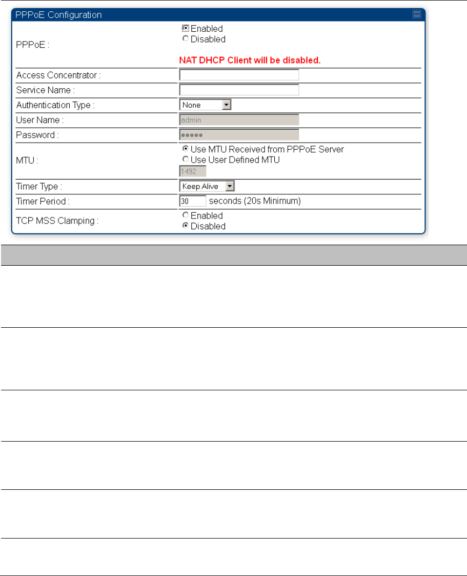
Chapter 7: Configuration Configuring IP and Ethernet interfaces
Page 7-59
Table 119 SM PPPoE attributes
Attribute Meaning
Access Concentrator An optional entry to set a specific access concentrator to connect to for the
PPPoE session. If this is blank, the SM will accept the first access
concentrator which matches the service name (if specified). This is limited to
32 characters.
Service Name An optional entry to set a specific service name to connect to for the PPPoE
session. If this is left blank the SM will accept the first service option that
comes back from the access concentrator specified above, if any. This is
limited to 32 characters.
Authentication Type
None means that no PPPoE authentication is implemented
CHAP/PAP means that CHAP authentication is attempted first, then PAP
authentication. The same password is used for both types.
User Name This is the CHAP/PAP user name that is used if CHAP/PAP authentication is
selected. If None is selected for authentication then this field is unused. This
is limited to 32 characters.
Password This is the CHAP/PAP password that is used if PAP authentication is
selected. If None is selected for authentication then this field is unused. This
is limited to 32 characters.
MTU
Use MTU Received from PPPoE Server causes the SM to use the MRU of
the PPPoE server received in LCP as the MTU for the PPPoE link.

Chapter 7: Configuration Configuring IP and Ethernet interfaces
Page 7-60
Use User Defined MTU allows the operator to specify an MTU value to use
to override any MTU that may be determined in the LCP phase of PPPoE
session setup. If this is selected, the user is able to enter an MTU value up to
1492. However, if the MTU determined in LCP negotiations is less than this
user-specified value, the SM will use the smaller value as its MTU for the
PPPoE link.
Timer Type
Keep Alive is the default timer type. This timer will enable a keepalive that
will check the status of the link periodically. The user can set a keepalive
period. If no data is seen from the PPPoE server for that period, the link is
taken down and a reconnection attempt is started. For marginal links, the
keep alive timer can be useful so that the session will stay alive over periodic
dropouts. The keepalive timer must be set such that the session can outlast
any session drop. Some PPPoE servers will have a session check timer of
their own so that the timeouts of the server and the SM are in sync, to ensure
one side does not drop the session prematurely.
Idle Timeout enables an idle timer that checks the usage of the link from the
customer side. If there is no data seen from the customer for the idle timeout
period, the PPPoE session is dropped. Once data starts flowing from the
customer again, the session is started up again. This timer is useful for users
who may not be using the connection frequently. If the session is idle for long
periods of time, this timer will allow the resources used by the session to be
returned to the server. Once the connection is used again by the customer,
the link is reestablished automatically.
Timer Period The length in seconds of the PPPoE keepalive timer.
TCP MSS Clamping
If this is enabled, then the SM will alter TCP SYN and SYN-ACK packets by
changing the Maximum Segment Size to be compatible with the current MTU
of the PPPoE link. This way, the user does not have to worry about MTU on
the client side for TCP packets. The MSS is set to the current MTU – 40 (20
bytes for IP headers and 20 bytes for TCP headers). This will cause the
application on the client side to not send any TCP packets larger than the
MTU. If the network is exhibiting large packet loss, try enabling this option.
This may not be an option on the PPPoE server itself. The SM will NOT
reassemble IP fragments, so if the MTUs are incorrect on the end stations,
then MSS clamping will solve the problem for TCP connections.
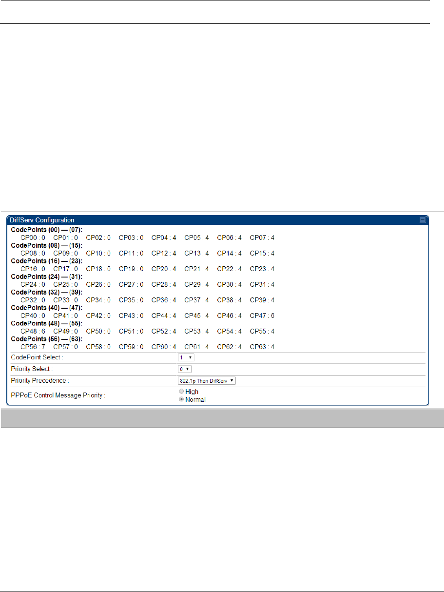
Chapter 7: Configuration Configuring IP and Ethernet interfaces
Page 7-61
IP4 and IPv6
Applicable products PMP : AP SM PTP: BHM BMS
IPv4 and IPv6 Prioritization
450 Platform Family provides operators the ability to prioritize IPv6 traffic in addition to IPv4 traffic.
IPv6/IPv4 prioritization can be configured by selecting a CodePoint and the corresponding priority
from the GUI of the AP/BHM and the IPv6/IPv4 packet is set up accordingly. There is no GUI option
for selecting IPv6 or IPv4 priority. Once the priority is set, it is set for IPv4 and IPv6 packets.
Configuring IPv4 and IPv6 Priority
IPv4 and IPv6 prioritization is set using the DiffServ tab on the AP/BHM and SM/BHS (located at
Configuration > DiffServ). A priority set to a specific CodePoint will apply to both IPv4 and IPv6
traffic.
Table 120 DiffServ attributes – AP/BHM
Attribute Meaning
CodePoint 1 through
CodePoint 47
CodePoint 49 through
CodePoint 55
CodePoint 57 through
CodePoint 63
Priorities of 0 through 3 map to the low-priority channel; 4 through 7 to the
high- priority channel. The mappings are the same as 802.1p VLAN priorities.
Consistent with RFC 2474
CodePoint 0 is predefined to a fixed priority value of 0 (low-priority channel).
CodePoint 48 is predefined to a fixed priority value of 6 (high-priority
channel). CodePoint 56 is predefined to a fixed priority value of 7 (high-
priority channel).
Operator cannot change any of these three fixed priority values. Among the
settable parameters, the priority values (and therefore the handling of packets
in the high or low priority channel) are set in the AP/BHM for all downlinks
within the sector and in the SM/BHS for each uplink.

Chapter 7: Configuration Configuring IP and Ethernet interfaces
Page 7-62
CodePoint Select This represents the CodePoint Selection to be modified via Priority Select
Priority Select The priority setting input for the CodePoint selected in CodePoint Select
Priority Precedence Allows operator to decide if 802.1p or DiffServ priority bits must be used first
when making priority decisions.
PPPoE Control
Message Priority
Operators may configure the AP/BHM to utilize the high priority channel for
PPPoE control messages. Configuring the AP/BHM in this fashion can benefit
the continuity of PPPoE connections when there are issues with PPPoE
sessions being dropped in the network. This prioritization may be configured
in the DiffServ tab in the Configuration menu of the AP/BHM.
IPv4 and IPv6 Filtering
The operator can filter (block) specified IPv6 protocols including IPv4 and ports from leaving the AP/BHM
and SM/BHS and entering the network. This protects the network from both intended and inadvertent
packet loading or probing by network users. By keeping the specified protocols or ports off the network,
this feature also provides a level of protection to users from each other.
Configuring IPv4 and IPv6 Filtering
IPv6 filters are set using the Protocol Filtering tab on the AP/BHM and SM/BHS (at Configuration >
Protocol Filtering). Once a filter is set for a packet type, those packets will not be sent over the RF
interface depending on “Filter Direction” setting.
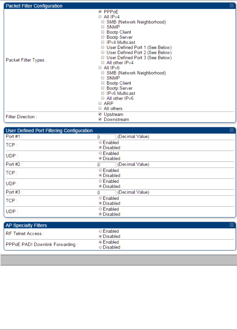
Chapter 7: Configuration Configuring IP and Ethernet interfaces
Page 7-63
Table 121 Packet Filter Configuration attributes
Attribute Meaning
Packet Filter Types
For any box selected, the Protocol and Port Filtering feature blocks the
associated protocol type.
To filter packets in any of the user-defined ports, you must do all of the
following:
Check the box for User Defined Port n (See Below) in the Packet Filter
Types section of this tab.
Provide a port number at Port #n. in the User Defined Port Filtering
Configuration section of this tab

Chapter 7: Configuration Configuring IP and Ethernet interfaces
Page 7-64
Enable TCP and/or UDP by clicking the associated radio button
Filter Direction Operators may choose to filter upstream (uplink) RF packets or downstream
(downlink) RF packets.
User Defined Port
Filtering Configuration
You can specify ports for which to block subscriber access, regardless of
whether NAT is enabled.
Chapter 7: Configuration Upgrading the software version and using CNUT
Page 7-65
Upgrading the software version and using
CNUT
This section consists of the following procedures:
Checking the installed software version on page 7-64
Upgrading to a new software version on page 7-64
Caution
If the link is operational, ensure that the remote end of the link is upgraded first using the
wireless connection, and then the local end can be upgraded. Otherwise, the remote end
may not be accessible.
Use CNUT 4.10.4 or later version and always refer to the software release notes before
upgrading system software. The release notes are available at:
https://support.cambiumnetworks.com/files/pmp450
https://support.cambiumnetworks.com/files/ptp450
Checking the installed software version
To check the installed software version, follow these instructions:
Procedure 18
Checking the installed software version
1 Click on
General
tab under
Home
menu.
2 Note the installed Software Version (under Device Information):
PMP/PTP 450/450i/450m
3 Go to the support website (see Contacting Cambium Networks on page 1) and find Point-to-
Multipoint software updates. Check that the latest 450 Platform Family software version is the
same as the installed Software Version.
4 To upgrade software to the latest version, see Upgrading to a new software version on page 7-
64.
Upgrading to a new software version
All 450 platform modules are upgraded using the Canopy Network Updater Tool. The Canopy Network
Updater Tool (CNUT) manages and automates the software upgrade process for a Canopy radio, or
CMM4 (but not its 14-port switch) across the network. This eliminates the need for an administrator to visit
each radio in the network (or each AP/BHM while using the Autoupdate feature) to upgrade the modules.

Chapter 7: Configuration Upgrading the software version and using CNUT
Page 7-66
Note
Please ensure that you have the most up-to-date version of CNUT by browsing to the
Customer Support Web Page located:
http://www.cambiumnetworks.com/support/management-tools/cnut
This section includes an example of updating a single unit before deployment. System-wide upgrading
procedures may be found in the CNUT Online Help manual, which can be found on the Cambium support
website (see Contacting Cambium Networks on page 1).
CNUT functions
The Canopy Network Updater tool has the following functions:
Automatically discovers all network elements
Executes a UDP command that initiates and terminates the Auto-update mode within APs/BHMs.
This command is both secure and convenient:
o For security, the AP/BHM accepts this command from only the IP address that you specify in the
Configuration page of the AP/BHM.
o For convenience, Network Updater automatically sets this Configuration parameter in the
APs/BHMs to the IP address of the Network Updater server when the server performs any of the
update commands.
CNUT supports HTTP and HTTPS
Allows you to choose the following among updating:
o Your entire network.
o Only elements that you select.
o Only network branches that you select.
Provides a Script Engine that you can use with any script that:
o You define.
o Cambium supplies.
Configurability of any of the following to be the file server for image files:
o The AP/BHM, for traditional file serving via UDP commands and monitoring via UDP messaging
o CNUT HTTP/HTTPS Server, for upgrading via SNMP commands and monitoring via SNMP
messaging. This also supports an option to either set the image order specifically for this file
server or to allow the AP to determine the order.
o Local TFTP Server, for traditional file serving via UDP commands and monitoring via UDP
messaging. This supports setting the number of simultaneous image transfers per AP/BHM
The capability to launch a test of connectivity and operational status of the local HTTP, HTTPS and
TFTP file servers
An interface that supports efficient specification of the proper IP address for the local file server(s)
where Network Updater resides on a multi-homed computer
An md5 checksum calculator utility for identifying corruption of downloaded image files before
Network Updater is set to apply them.
Network element groups
With the Canopy Network Updater Tool, you can identify element groups composed of network elements
that you select. Identifying these element groups does the following:
Chapter 7: Configuration Upgrading the software version and using CNUT
Page 7-67
Organizes the display of elements (for example, by region or by AP/BHM cluster).
Allows to:
o Perform an operation on all elements in the group simultaneously.
o Set group-level defaults for ftp password access and SNMP Community String (defaults that can
be overridden in an individual element when necessary).
Network layers
A typical network contains multiple layers of elements, with each layer farther from the Point of Presence.
For example, SMs (or BHS) are behind an AP/BHM and thus, in this context, at a lower layer than the
AP/BHM. Correctly portraying these layers in Network Updater is essential so that Network Updater can
perform radio and AP/BHM cluster upgrades in an appropriate order.
Script engine
Script Engine is the capability in Network Updater that executes any user-defined script against any
network element or element group. This capability is useful for network management, especially for
scripts that you repetitively execute across your network.
The Autodiscovery capability in Network Updater finds all of your network elements. This comprehensive
discovery:
Ensures that, when you intend to execute a script against all elements, the script is indeed executed
against all elements.
Maintains master lists of elements (element groups) against which you selectively execute scripts.
The following scripts are included with CNUT:
Gather Customer Support Information
Set Access Point Authentication Mode
Set Autoupdate Address on APs/BHMs
Set SNMP Accessibility
Reset Unit

Chapter 7: Configuration Upgrading the software version and using CNUT
Page 7-68
Software dependencies for CNUT
CNUT functionality requires
one of the following operating systems
o Windows® 2000
o Windows Server 2003
o Windows 7 and Windows 8
o Windows XP or XP Professional
o Red Hat Enterprise Linux (32-bit) Version 4 or 5
Java™ Runtime Version 2.0 or later (installed by the CNUT installation tool)
CNUT download
CNUT can be downloaded together with each system release that supports CNUT. Software for these
system releases is available from http://www.cambiumnetworks.com/support/management-tools/cnut/, as
either:
A .zip file for use without the CNUT application.
A .pkg file that the CNUT application can open.
Upgrading a module prior to deployment
To upgrade to a new software version, follow this:
Procedure 19 Upgrading a module prior to deployment
1 Go to the support website (see Contacting Cambium Networks on page 1) and find Point-to-
Multipoint software updates. Download and save the required software image.
2 Start CNUT
3 If you don’t start up with a blank new network file in CNUT, then open a new network file with
the New Network Archive operation (located at File > New Network).
4 Enter a new network element to the empty network tree5-9 using the Add Elements to
Network Root operation (located at Edit > Add Elements to Network Root).
5 In the Add Elements dialogue, select a type of Access Point or Subscriber Module and enter
the IP address of 169.254.1.1.
6 Make sure that the proper Installation Package is active with the Package Manager dialogue
(located at Update > Manage Packages).
7 To verify connectivity with the radio, perform a Refresh, Discover Entire Network operation
(located at View > Refresh/Discover Entire Network). You must see the details columns for
the new element filled in with ESN and software version information.
8 Initiate the upgrade of the radio using Update Entire Network Root operation (located at
Update > Update Entire Network Root). When this operation finishes, the radio is done being
upgraded.
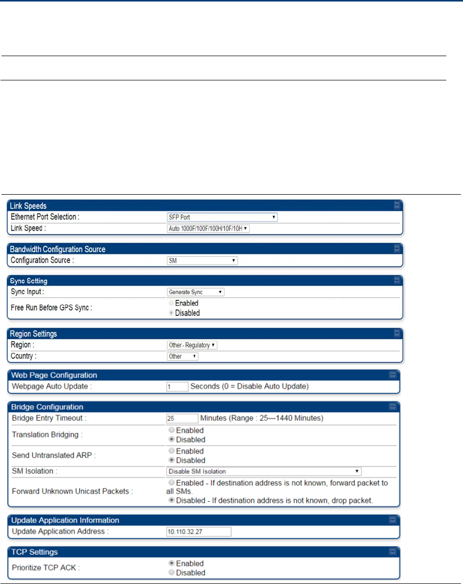
Chapter 7: Configuration General configuration
Page 7-69
General configuration
The
Configuration > General
page of the AP/BMH or BHM/BHS contains many of the configurable
parameters that define how the ratio’s operate in sector or backhaul.
Applicable products PMP :
AP
SM
PTP:
BHM
BMS
PMP 450m and PMP/PTP 450i Series
General page - PMP 450i AP
The General page of AP is explained in Table 122.
Table 122
General page attributes – PMP 450i AP
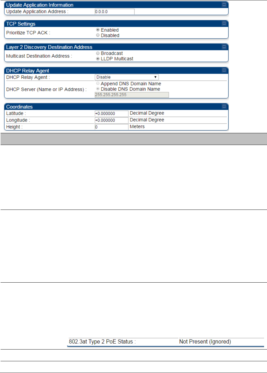
Chapter 7: Configuration General configuration
Page 7-70
Attribute Meaning
Ethernet Port
Selection
Ethernet Port selection is applicable to the 450m platform only with two
choices in the drop-down list:
Main: A selection of main indicates that link connectivity and power to the
450m is provided through the RF45 connection on the Main port of the AP
SFP: A selection of SFP indicates that link connectivity will be provided
through the SFP port on the 450m
Power continues to be provided via the RJ45 Main port
Link Speeds
From the drop-down list of options, select the type of link speed for the
Ethernet connection. The Auto settings allow the two ends of the link to
automatically negotiate with each other the best possible speed, and check
whether the Ethernet traffic is full duplex or half duplex.
However, some Ethernet links work best when either:
both ends are set to the same forced selection
both ends are set to auto-negotiate and both have capability in least one
common speed and traffic type combination.
802.3at Type 2 PoE
Status and
PoE Classification
(PMP 450i Series
only)
When the PoE Classification functionality is enabled and if Type 2 power is
not present, the PAs do not power up and draw too much power.
By default, the PoE Classification feature is disabled and the PAs will power
up regardless of the classification presented by the power source.
This is supported only on 450i series devices.
PoE Classification configuration status also can be check under home >
General > Device Information tab:
Configuration Source See Setting the Configuration Source on page 7-203.
Sync Input See Configuring synchronization on page 7-97
Chapter 7: Configuration General configuration
Page 7-71
Device Type
Standard
: The Autosync mechanism will source GPS synchronization from
the AP’s RJ-11 port, the AP’s power port, or from the device on-board GPS
module.
Remote
: The Autosync mechanism will source GPS synchronization from the
AP’s RJ-11 port or from the device on-board GPS module.
Region From the drop-down list, select the region in which the radio is operating.
Country From the drop-down list, select the country in which the radio is operating.
Unlike selections in other parameters, your
Country
selection requires a
Save Changes
and a
Reboot
cycle before it will force the context-sensitive
GUI to display related options (for example,
Alternate Frequency Carrier 1
and 2
in the
Configuration
>
Radio
tab).
PMP 450i Series ODUs shipped to the United States is locked to a Region
Code setting of “United States”. Units shipped to regions other than the
United States must be configured with the corresponding Region Code to
comply with local regulatory requirements.
Country Code settings affect the radios in the following ways:
Maximum transmit power limiting (based on radio transmitter power plus
configured antenna gain)
DFS operation is enabled based on the configured region code, if
applicable
For more information on how transmit power limiting and DFS is implemented
for each country, see the
PMP 450 Planning Guide
.
Webpage Auto
Update
Enter the frequency (in seconds) for the web browser to automatically refresh
the web-based interface. The default setting is 0. The 0 setting causes the
web-based interface to never be automatically refreshed.
Bridge Entry Timeout Specify the appropriate bridge timeout for correct network operation with the
existing network infrastructure. The Bridge Entry Timeout must be a longer
period than the ARP (Address Resolution Protocol) cache timeout of the
router that feeds the network.
Caution
An inappropriately low Bridge Entry Timeout setting may lead to
temporary loss of communication with some end users.
Translation Bridging Optionally, you can configure the AP to change the source MAC address in
every packet it receives from its SMs to the MAC address of the SM that
bridged the packet, before forwarding the packet toward the public network. If
you do, then:
Not more than 128 IP devices at any time are valid to send data to the AP
from behind the SM.
SM populates the Translation Table tab of its Statistics web page, displaying
the MAC address and IP address of all the valid connected devices.

Chapter 7: Configuration General configuration
Page 7-72
Each entry in the Translation Table is associated with the number of minutes
that have elapsed since the last packet transfer between the connected
device and the SM.
If 128 are connected and another attempts to connect:
If no Translation Table entry is older than 255 minutes, the attempt is ignored.
If an entry is older than 255 minutes, the oldest entry is removed and the
attempt is successful.
the Send Untranslated ARP parameter in the General tab of the Configuration
page can be:
Disabled, so that the AP overwrites the MAC address in Address Resolution
Protocol (ARP) packets before forwarding them.
Enabled, so that the AP forwards ARP packets regardless of whether it has
overwritten the MAC address.
When this feature is disabled, the setting of the Send Untranslated ARP
parameter has no effect, because all packets are forwarded untranslated
(with the source MAC address intact).
Send Untranslated
ARP
If the Translation Bridging parameter is set to Enabled, then the Send
Untranslated ARP parameter can be:
Disabled - so that the AP will overwrite the MAC address in Address
Resolution Protocol (ARP) packets before forwarding them.
Enabled - so that the AP will forward ARP packets regardless of whether it
has overwritten the MAC address.
If the Translation Bridging parameter is set to Disabled, then the Send
Untranslated ARP parameter has no effect.
SM Isolation
Prevent or allow SM-to-SM communication by selecting from the following
drop-down menu items:
Disable SM Isolation (the default selection). This allows full communication
between SMs.
Block SM Packets from being forwarded. This prevents both
multicast/broadcast and unicast SM-to-SM communication.
Block and Forward SM Packets to Backbone. This not only prevents
multicast/broadcast and unicast SM-to-SM communication but also sends the
packets, which otherwise are handled SM to SM, through the Ethernet port of
the AP.
Forward Unknown
Unicast Packets
Enabled: All unknown Unicast packets (no entry in the AP’s bridge table)
received via the AP’s Ethernet LAN interface are forwarded to registered
SMs. If the target device is situated beneath a particular SM, when the device
responds the SM and AP will learn and add the device to their bridge tables
so that subsequent packets to that device is bridged to the proper SM.
Disabled: All unknown Unicast packets (no entry in the AP’s bridge table)
received via the AP’s Ethernet LAN interface are discarded at the AP.
Update Application
Address
Enter the address of the server to access for software updates on this AP and
registered SMs.

Chapter 7: Configuration General configuration
Page 7-73
Prioritize TCP ACK To reduce the likelihood of TCP acknowledgement packets being dropped,
set this parameter to Enabled. This can improve throughput that the end user
perceives during transient periods of congestion on the link that is carrying
acknowledgements. This parameter, when enabled, can be particularly useful
when running bi-direction FTP sessions over the link. If a link is primarily used
for video surveillance, it is recommended to set this parameter to Disable.
Multicast Destination
Address
Using Link Layer Discovery Protocol (LLDP), a module exchanges multicast
addresses with the device to which it is wired on the Ethernet interface.
Although some switches (CMM4, for example) do not pass LLDP addresses
upward in the network, a radio can pass it as the value of the Multicast
Destination Address parameter value in the connected device that has it
populated.
DHCP Relay Agent The AP may act as a DHCP relay for SMs and CPEs underneath it. The AP
will make use of the DHCP Option 82 (DHCP Relay Agent Information) from
RFC 3046 when performing relay functions. The AP offers two types of DHCP
relay functionality:
Full Relay Information. Configuring the DHCP Full Relay Operation will take
broadcast DHCP packets and send them to a Unicast server in unicast mode.
This way the DHCP requests and replies can be routed like any other UDP
packet.
Only Insert Option 82. This option leaves the DHCP request on its broadcast
domain as opposed to DHCP Full Relay Operation which will turn it into a
unicast packet.
In order to accommodate setting up pools or classes for different VLANs, the
Option 82 field will include information to tell the server what VLAN the client
is on.
DHCP Server (Name
or IP Address)
The DHCP relay server may be either a DNS name or a static IP address in
dotted decimal notation. Additionally the management DNS domain name
may be toggled such that the name of the DHCP relay server only needs to
be specified and the DNS domain name is automatically appended to that
name. The default DHCP relay server addresses is 255.255.255.255 with the
appending of the DNS domain name disabled.
Latitude
Longitude
Height
Physical radio location data may be configured via the Latitude, Longitude
and Height fields.
Latitude and Longitude is measured in Decimal Degree while the Height is
calculated in Meters.
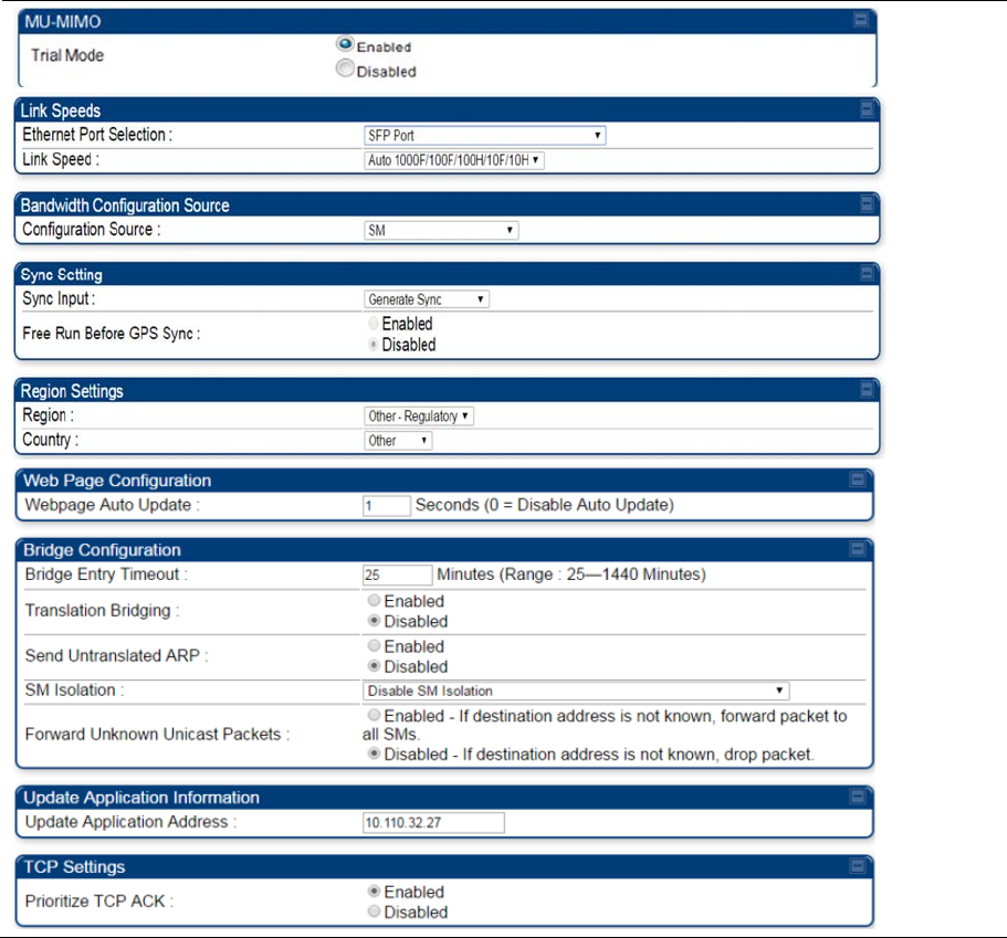
Chapter 7: Configuration General configuration
Page 7-74
General page - PMP 450m AP
The General page of AP is explained in Table 123.
Table 123
General page attributes –PMP 450m AP
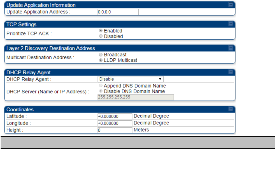
Chapter 7: Configuration General configuration
Page 7-75
Attribute Meaning
Trial Mode This parameters allows to enable or disable Trial mode for radios with a
Limited key. Once the trial key is applied, the 30-day trial can be enabled or
disabled at any time.
For information about remaining attributes, refer Table 122.
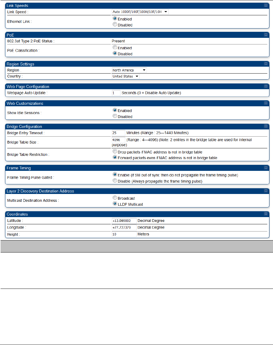
Chapter 7: Configuration General configuration
Page 7-76
General page - PMP 450i SM
The General page of PMP 450i SM is explained in Table 124. The General page of PMP 450 SM looks
the same as PMP 450i SM.
Table 124 General page attributes – PMP 450i SM
Attribute Meaning
Link Speeds From the drop-down list of options, select the type of link speed for the
Ethernet connection. The default for this parameter is that all speeds are
selected. The recommended setting is a single speed selection for all APs
and SMs in the operator network.
802.3at Type 2 PoE
Status and
PoE Classification
When the PoE Classification functionality is enabled and if Type 2 power is
not present, the Pas do not power up and draw too much power.
By default, the PoE Classification feature is disabled and the Pas will power
up regardless of the classification presented by the power source.
This is supported only on 450i series ODUs.
PoE Classification configuration status also can be check under home >
General > Device Information tab:

Chapter 7: Configuration General configuration
Page 7-77
Ethernet Link
Enable/Disable
Specify whether to enable or disable Ethernet/802.3 connectivity on the wired
port of the SM. This parameter has no effect on the wireless link. When you
select Enable, this feature allows traffic on the Ethernet/802.3 port. This is the
factory default state of the port. When you select Disable, this feature
prevents traffic on the port. Typical cases of when you may want to select
Disable include:
The subscriber is delinquent with payment(s).
You suspect that the subscriber is sending or flooding undesired broadcast
packets into the network, such as when
a virus is present in the subscriber’s computing device.
the subscriber’s home router is improperly configured.
Region This parameter allows you to set the region in which the radio will operate.
The SM radio automatically inherits the Region type of the master. This
behavior ignores the value of the Region parameter in the SM, even when
the value is None. Nevertheless, since future system software releases may
read the value in order to configure some other region-sensitive feature(s),
this parameter must be always set to the value that corresponds to the local
region.
Country
This parameter allows you to set the country in which the radio will operate.
The SM radio automatically inherits the Country Code type of the master. This
behavior ignores the value of the Country parameter in the SM, even when
the value is None. Nevertheless, since future system software releases may
read the value in order to configure some other region-sensitive feature(s),
this parameter must be always set to the value that corresponds to the local
region.
PMP/PTP 450i Series ODU shipped to the United States is locked to a
Region Code setting of “United States”. Units shipped to regions other than
the United States must be configured with the corresponding Region Code to
comply with local regulatory requirements.
Webpage Auto
Update
See Table 122 General page attributes – PMP 450i AP on page 7-68
Show Idle Sessions This parameter allows to enable or disable displaying idle sessions.
Bridge Entry Timeout Specify the appropriate bridge timeout for correct network operation with the
existing network infrastructure. Timeout occurs when the AP encounters no
activity with the SM (whose MAC address is the bridge entry) within the
interval that this parameter specifies. The Bridge Entry Timeout must be a
longer period than the ARP (Address Resolution Protocol) cache timeout of
the router that feeds the network.
Chapter 7: Configuration General configuration
Page 7-78
Caution
This parameter governs the timeout interval, even if a router in
the system has a longer timeout interval. The default value of
this field is 25 (minutes).
An inappropriately low Bridge Entry Timeout setting may lead to
temporary loss of communication with some end users.
Bridge Table Size This parameter allows to restrict devices to connect to the SM. It is
configurable from 4 to 4096.
Note
Configure Bridge Table Restriction parameter to Drop packets if
MAC address is not in bridge table option to restrict the number
of devices configured from connecting to SM.
Bridge Table
Restriction
This parameter allows to either allow or restrict devices to connect to SM
using the following options:
Drop packets if MAC address is not in bridge table: Select this option to
restrict communication from devices not listed in bridge table.
Forward packets even if MAC address is not in bridge table: Select this
option to allow communication from any device.
Frame Timing Pulse
Gated
If this SM extends the sync pulse to a BH master or an AP, select either
Enable—If this SM loses sync from the AP, then do not propagate a sync
pulse to the BH timing master or other AP. This setting prevents interference
in the event that the SM loses sync.
Disable—If this SM loses sync from the AP, then propagate the sync pulse to
the BH timing master or other AP.
Multicast Destination
Address
Using Link Layer Discovery Protocol (LLDP), a module exchanges multicast
addresses with the device to which it is wired on the Ethernet interface.
Although some switches (CMM4, for example) do not pass LLDP addresses
upward in the network, a radio can pass it as the value of the Multicast
Destination Address parameter value in the connected device that has it
populated.
Coordinates Physical radio location data may be configured via the Latitude, Longitude
and Height fields.
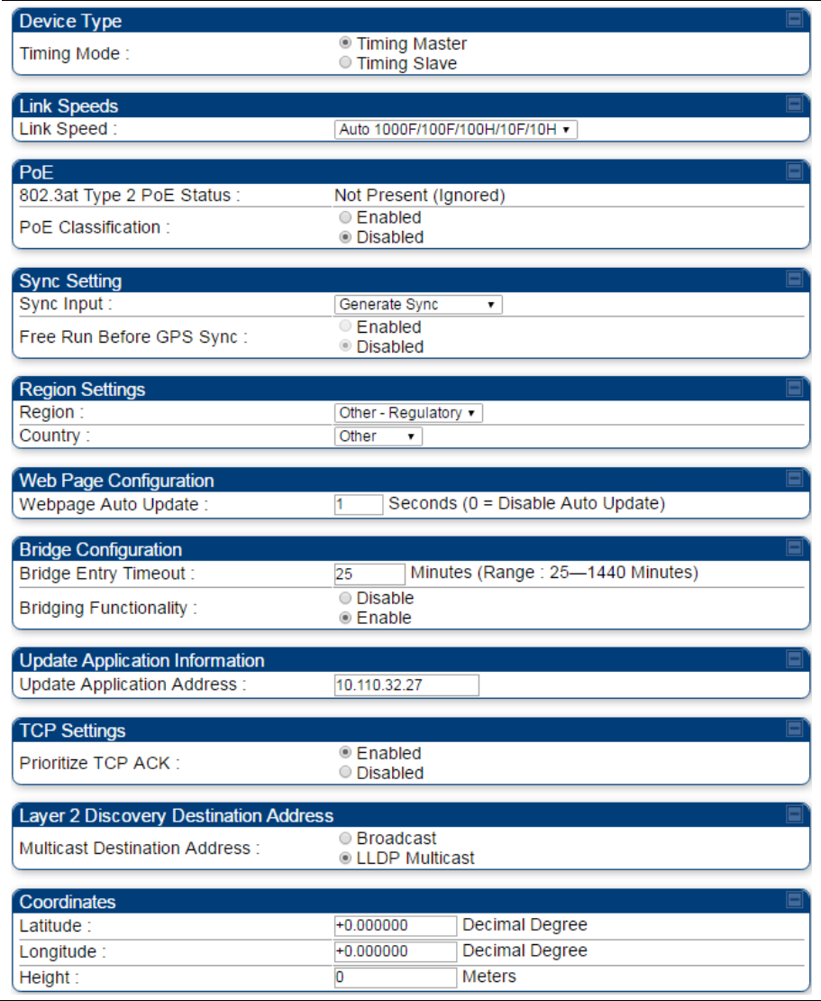
Chapter 7: Configuration General configuration
Page 7-79
General page - PTP 450i BHM
The General page of BHM is explained in Table 125. The General page of PTP 450 BHM looks the same
as PTP 450i BHM.
Table 125 General page attributes – PTP 450i BHM
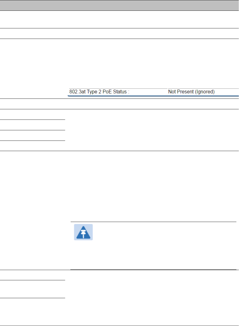
Chapter 7: Configuration General configuration
Page 7-80
Attribute Meaning
Timing Mode Allows the user to choose the mode between Timing Master and Timing
Slave.
Link Speed See Table 122 General page attributes – PMP 450i AP on page 7-68
802.3at Type 2 PoE
Status and
PoE Classification
When the PoE Classification functionality is enabled and if Type 2 power
is not present, the PAs do not power up and draw too much power.
By default, the PoE Classification feature is disabled and the PAs will
power up regardless of the classification presented by the power source.
This is supported only on 450i Series ODUs.
PoE Classification configuration status also can be check under home >
General > Device Information tab:
Sync Input See Configuring synchronization on page 7-97
Region
See Table 122 General page attributes – PMP 450i AP on page 7-68
Country
Webpage Auto Update
Bridge Entry Timeout
Bridging Functionality Select whether you want bridge table filtering active (Enable) or not
(Disable) on this BH.
Disable: allows user to use redundant BHs without causing network
addressing problems. Through a spanning tree protocol, this reduces the
convergence time from 25 minutes to few seconds. However, you must
disable bridge table filtering as only a deliberate part of your overall
network design since disabling it allows unwanted traffic across the
wireless interface.
Enable: Allows user to enable bridge functionality.
Note
Specify the appropriate bridge timeout for correct network
operation with the existing network infrastructure. The
Bridge Entry Timeout must be a longer period than the ARP
(Address Resolution Protocol) cache timeout of the router
that feeds the network.
Prioritize TCP ACK
See Table 122 General page attributes – PMP 450i AP on page 7-68
Multicast Destination
Address
Latitude
Longitude
Height
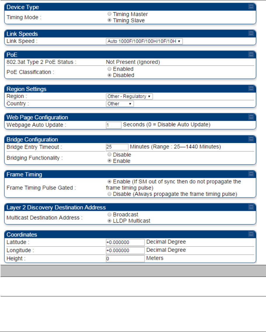
Chapter 7: Configuration General configuration
Page 7-81
General page - PTP 450i BHS
The General page of PTP 450i BHS is explained in Table 126. The General page of PTP 450 BHS looks
the same as PTP 450i BHS.
Table 126 General page attributes – PTP 450i BHS
Attribute Meaning
Timing Mode Allows the user to choose the mode between Timing Master and Timing
Slave.
Link Speed From the drop-down list of options, select the type of link speed for the
Ethernet connection. The default for this parameter is that all speeds are
selected. The recommended setting is a single speed selection for all BHMs
and BHSs in the operator network.
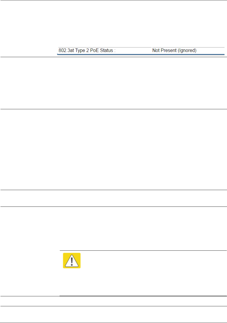
Chapter 7: Configuration General configuration
Page 7-82
802.3at Type 2 PoE
Status and
PoE Classification
When the PoE Classification functionality is enabled and if Type 2 power is
not present, the PAs do not power up and draw too much power.
By default, the PoE Classification feature is disabled and the PAs will power
up regardless of the classification presented by the power source.
This is supported only on 450i Series ODUs.
PoE Classification configuration status also can be check under home >
General > Device Information tab:
Region This parameter allows you to set the region in which the radio will operate.
The BHS radio automatically inherits the Region type of the master. This
behavior ignores the value of the Region parameter in the BHS, even when
the value is None. Nevertheless, since future system software releases may
read the value in order to configure some other region-sensitive feature(s),
this parameter must be always set to the value that corresponds to the local
region.
Country
This parameter allows you to set the country in which the radio will operate.
The BHS radio automatically inherits the Country Code type of the master.
This behavior ignores the value of the Country parameter in the BHS, even
when the value is None. Nevertheless, since future system software releases
may read the value in order to configure some other region-sensitive
feature(s), this parameter must be always set to the value that corresponds to
the local region.
PMP/PTP 450i Series ODU shipped to the United States is locked to a
Region Code setting of “United States”. Units shipped to regions other than
the United States must be configured with the corresponding Region Code to
comply with local regulatory requirements.
Webpage Auto
Update
See Table 122 General page attributes – PMP 450i AP on page 7-68
Bridge Entry Timeout Specify the appropriate bridge timeout for correct network operation with the
existing network infrastructure. Timeout occurs when the BHM encounters no
activity with the BHS (whose MAC address is the bridge entry) within the
interval that this parameter specifies. The Bridge Entry Timeout must be a
longer period than the ARP (Address Resolution Protocol) cache timeout of
the router that feeds the network.
Caution
This parameter governs the timeout interval, even if a router in
the system has a longer timeout interval. The default value of
this field is 25 (minutes).
An inappropriately low Bridge Entry Timeout setting may lead to
temporary loss of communication with some end users.
Bridging Functionality See Table 122 General page attributes – PMP 450i AP on page 7-68
Frame Timing Pulse
Gated
If this BHS extends the sync pulse to a BH master or an BHM, select either

Chapter 7: Configuration General configuration
Page 7-83
Enable—If this BHS loses sync from the BHM, then do not propagate a sync
pulse to the BH timing master or other BHM. This setting prevents
interference in the event that the BHS loses sync.
Disable—If this BHS loses sync from the BHM, then propagate the sync
pulse to the BH timing master or other BHM.
Multicast Destination
Address
See Table 122 General page attributes – PMP 450i AP on page 7-68
Latitude
Longitude
Height
See Table 122 General page attributes – PMP 450i AP on page 7-68
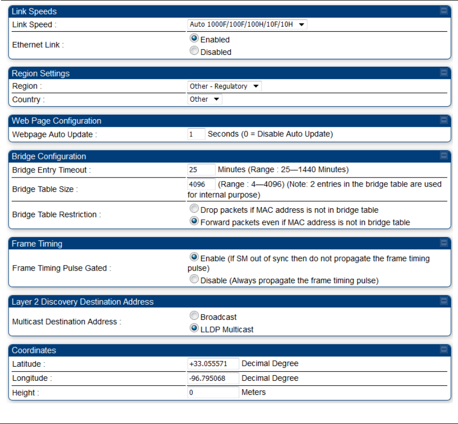
Chapter 7: Configuration General configuration
Page 7-84
General page - PMP 450b SM
The General page of PMP 450b SM is explained in Table 127. The General page of PMP 450b SM looks
the same as PMP 450i SM.
Table 127 General page attributes – PMP 450i SM

Chapter 7: Configuration General configuration
Page 7-85
Attribute Meaning
Link Speed From the drop-down list of options, select the type of link speed for the
Ethernet connection. The default for this parameter is that all speeds are
selected. The recommended setting is a single speed selection for all APs
and SMs in the operator network.
Ethernet Link
Enabled/Disbaled
Specify whether to enable or disable Ethernet/802.3 connectivity on the wired
port of the SM. This parameter has no effect on the wireless link. When you
select Enable, this feature allows traffic on the Ethernet/802.3 port. This is the
factory default state of the port. When you select Disable, this feature
prevents traffic on the port. Typical cases of when you may want to select
Disable include:
The subscriber is delinquent with payment(s).
You suspect that the subscriber is sending or flooding undesired broadcast
packets into the network, such as when
a virus is present in the subscriber’s computing device.
the subscriber’s home router is improperly configured.
Region This parameter allows you to set the region in which the radio will operate.
The SM radio automatically inherits the Region type of the master. This
behavior ignores the value of the Region parameter in the SM, even when
the value is None. Nevertheless, since future system software releases may
read the value in order to configure some other region-sensitive feature(s),
this parameter must be always set to the value that corresponds to the local
region.
Country This parameter allows you to set the country in which the radio will operate.
The SM radio automatically inherits the Country Code type of the master. This
behavior ignores the value of the Country parameter in the SM, even when
the value is None. Nevertheless, since future system software releases may
read the value in order to configure some other region-sensitive feature(s),
this parameter must be always set to the value that corresponds to the local
region.
PMP/PTP 450i Series ODU shipped to the United States is locked to a
Region Code setting of “United States”. Units shipped to regions other than
the United States must be configured with the corresponding Region Code to
comply with local regulatory requirements.
Webpage Auto
Update
Enter the frequency (in seconds) for the web browser to automatically refresh
the web-based interface. The default setting is 0. The 0 setting causes the
web-based interface to never be automatically refreshed.
Chapter 7: Configuration General configuration
Page 7-86
Bridge Entry Timeout Specify the appropriate bridge timeout for correct network operation with the
existing network infrastructure. Timeout occurs when the AP encounters no
activity with the SM (whose MAC address is the bridge entry) within the
interval that this parameter specifies. The Bridge Entry Timeout must be a
longer period than the ARP (Address Resolution Protocol) cache timeout of
the router that feeds the network.
Caution
This parameter governs the timeout interval, even if a router in
the system has a longer timeout interval. The default value of
this field is 25 (minutes).
An inappropriately low Bridge Entry Timeout setting may lead to
temporary loss of communication with some end users.
Bridge Table Size This parameter allows to restrict devices to connect to the SM. It is
configurable from 4 to 4096.
Note
Configure Bridge Table Restriction parameter to Drop packets if
MAC address is not in bridge table option to restrict the number
of devices configured from connecting to SM.
Bridge Table
Restriction
This parameter allows to either allow or restrict devices to connect to SM
using the following options:
Drop packets if MAC address is not in bridge table: Select this option to
restrict communication from devices not listed in bridge table.
Forward packets even if MAC address is not in bridge table: Select this option
to allow communication from any device.
Frame Timing Pulse
Gated
If this SM extends the sync pulse to a BH master or an AP, select either
Enable—If this SM loses sync from the AP, then do not propagate a sync
pulse to the BH timing master or other AP. This setting prevents interference
in the event that the SM loses sync.
Disable—If this SM loses sync from the AP, then propagate the sync pulse to
the BH timing master or other AP.
Multicast Destination
Address
Using Link Layer Discovery Protocol (LLDP), a module exchanges multicast
addresses with the device to which it is wired on the Ethernet interface.
Although some switches (CMM4, for example) do not pass LLDP addresses
upward in the network, a radio can pass it as the value of the Multicast
Destination Address parameter value in the connected device that has it
populated.
Latitude
Longitude
Height
Physical radio location data may be configured via the Latitude, Longitude
and Height fields.
Latitude and Longitude is measured in Decimal Degree while the Height is
calculated in Meters.

Chapter 7: Configuration General configuration
Page 7-87
PMP/PTP 450 Series
Note
Refer Table 122 and Table 124 for PMP 450 AP/SM General page parameters details.
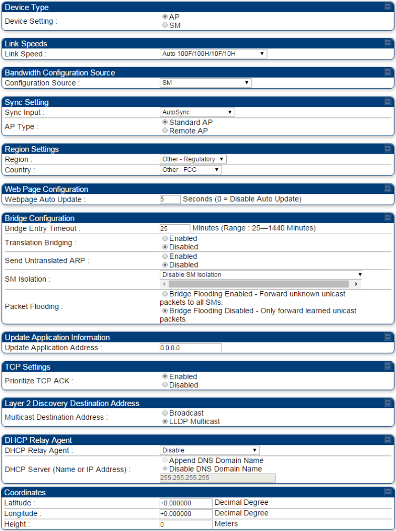
Chapter 7: Configuration General configuration
Page 7-88
General page - PMP 450 AP
Figure 133 General page attributes - PMP 450 AP
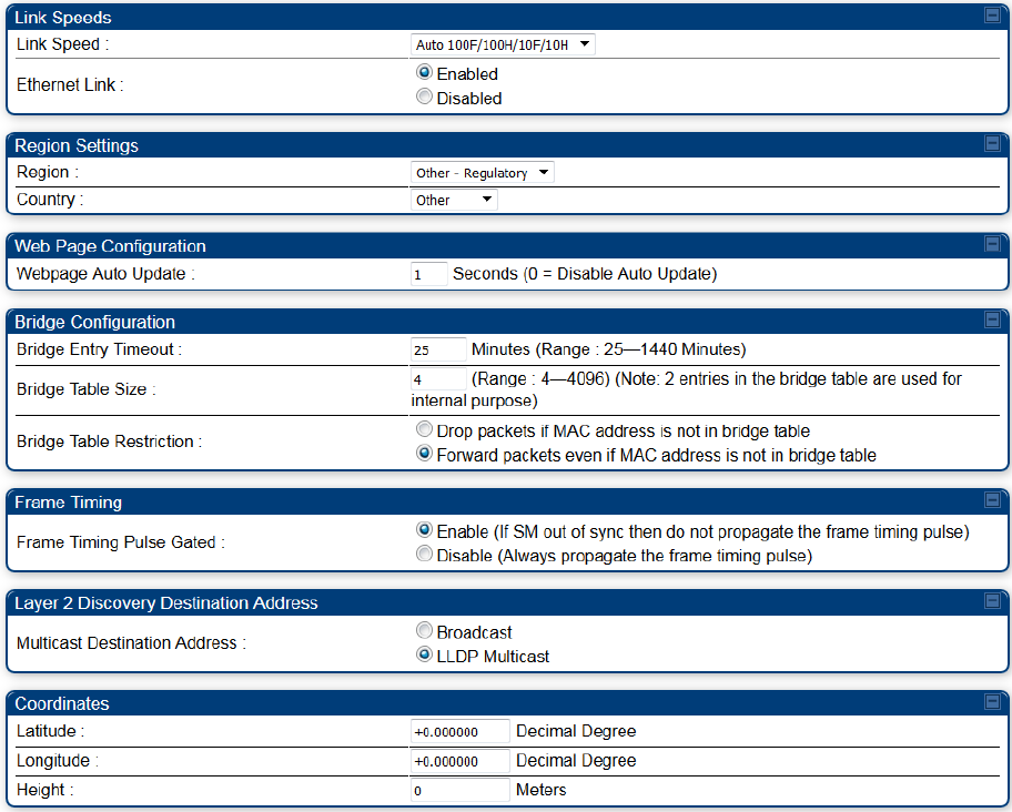
Chapter 7: Configuration General configuration
Page 7-89
General page - PMP 450 SM
Figure 134 General page attributes - PMP 450 SM
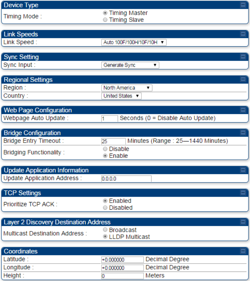
Chapter 7: Configuration General configuration
Page 7-90
General page – PTP 450 BHM
Figure 135 General page attributes - PTP 450 BHM
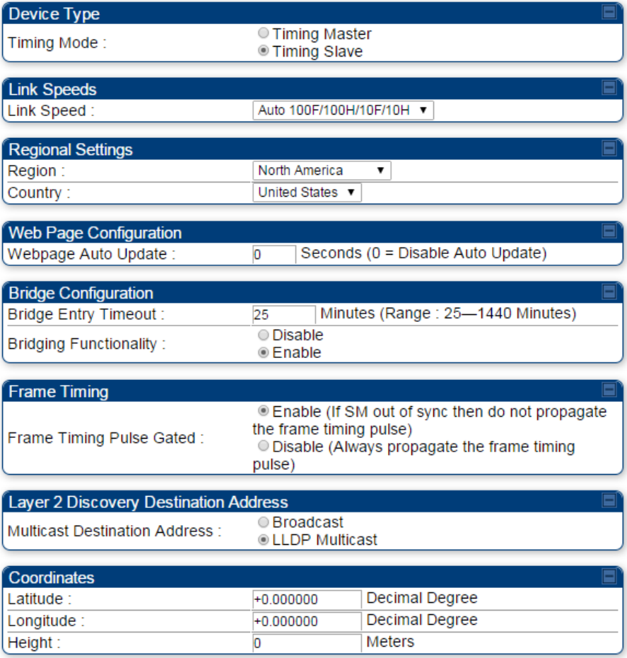
Chapter 7: Configuration General configuration
Page 7-91
General page – PTP 450 BHS
Figure 136 General page attributes - PTP 450 BHS

Chapter 7: Configuration Configuring Unit Settings page
Page 7-92
Configuring Unit Settings page
Applicable products PMP : AP SM PTP: BHM BMS
The Unit Settings page of the 450 Platform Family contains following options:
Unit-Wide Changes
Download Configuration File
Upload and Apply Configuration File (for AP and BHM)
LED Panel Settings (for SM and BHS)
Note
LED Panel setting is applicable for SM and BHS only.
Upload and Apply Configuration File attributes are not supported for SM and BHS.
The 450 Platform Family also supports import and export of configuration from the AP/BHM/SM/BHS as a
text file. The configuration file is in JSON format. The logged in user must be an ADMINISTRATOR in
order to export or import the configuration file.
The exported configuration file contains the complete configuration including all the default values. To
keep a backup of the current configuration, the file can be saved as-is and imported later.
The configuration file supports encrypted password. The exported configuration file will contain encrypted
password. The import of configuration can have either encrypted or plain text password in Configuration
fie. A new tab Encrypt the Password is added under Encrypted Password tab to generate encrypted
password for a given password.
The Import and Export procedure of configuration file is described in Import and Export of config file on
page 7-218.
LED Panel Mode has options select Revised mode and Legacy mode. The Legacy mode configures the
radio to operate with standard LED behavior.
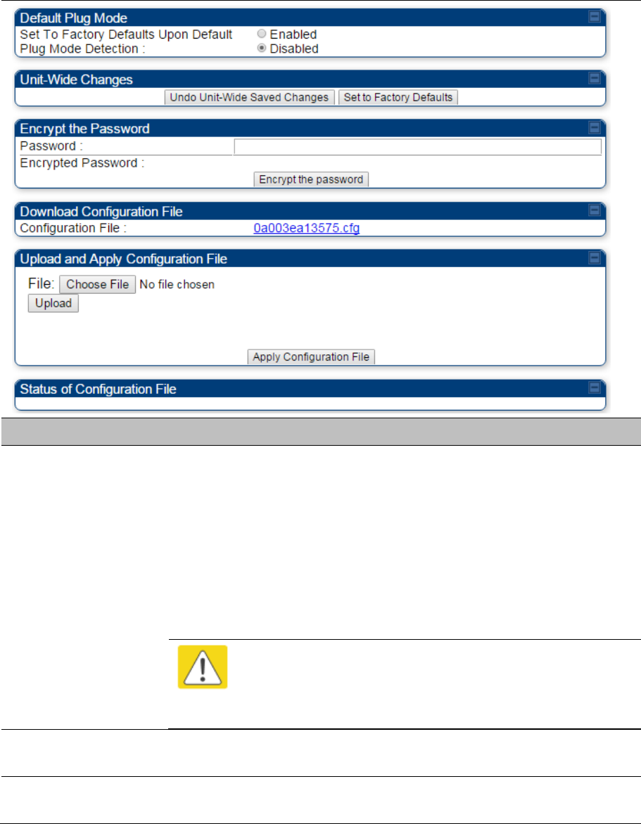
Chapter 7: Configuration Configuring Unit Settings page
Page 7-93
Unit Settings page of 450 Platform Family - AP/BHM
The Unit Setting page of AP/BHM is explained in Table 128.
Table 128 Unit Settings attributes – 450 Platform Family AP/BHM
Attribute Meaning
Set to Factory
Defaults Upon Default
Mode Detection
If Enabled is checked, then the default mode functions is enabled. When the
module is rebooted with Default mode enabled, it can be accessed at the IP
address 169.254.1.1 and no password, and all parameter values are reset to
defaults. A subscriber, technician, or other person who gains physical access
to the module and uses an override cannot see or learn the settings that were
previously configured in it.
If Disabled is checked, then the default mode functions is disabled.
See Radio recovery mode on page 1-26
Caution
When Set to Factory Defaults Upon Default Mode is set to
Enable, the radio does not select all of the frequencies for Radio
Frequency Scan Selection List. It needs to be selected manually.
Undo Unit-Wide
Saved Changes
When you click this button, any changes that you made in any tab but did not
commit by a reboot of the module are undone.
Set to Factory
Defaults
When you click this button, all configurable parameters on all tabs are reset to
the factory settings.
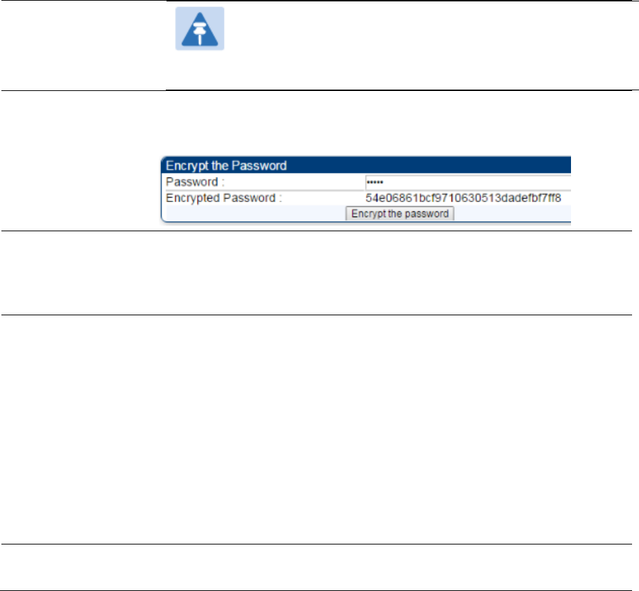
Chapter 7: Configuration Configuring Unit Settings page
Page 7-94
Note
This can be reverted by selecting "Undo Unit-Wide Saved
Changes", before rebooting the radio, though this is not
recommended.
Password This allows to provide encrypted password for a given password. On click of
‘Encrypt the password’ button, the Encrypted Password field will display
encrypted value of entered plain text password in ‘Password’ field.
Configuration File This allows to download the configuration file of the radio. This configuration
file contains the complete configuration including all the default values. The
configuration file is highlighted as downloadable link and the naming
convention is “<mac address of AP>.cfg”.
Apply Configuration
File
This allows to import and apply configuration to the AP.
Chose File: Select the file to upload the configuration. The configuration file
is named as “<file name>.cfg”.
Upload: Import the configuration to the AP.
Apply Configuration File: Apply the imported configuration file to the AP.
The imported configuration file may either contain a full device configuration
or a partial device configuration. If a partial configuration file is imported, only
the items contained in the file will be updated, the rest of the device
configuration parameters will remain the same. Operators may also include a
special flag in the configure file to instruct the device to first revert to factory
defaults then to apply the imported configuration.
Status of
Configuration file
This section shows the results of the upload.
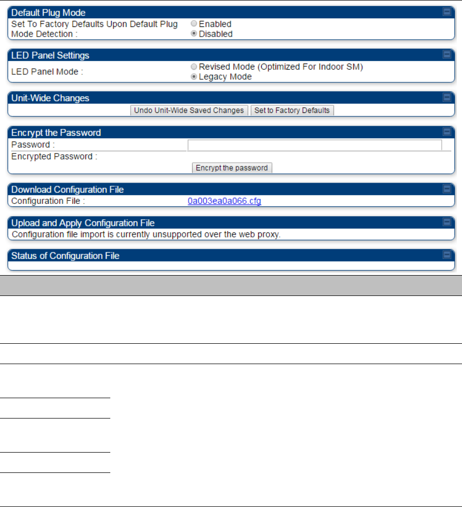
Chapter 7: Configuration Configuring Unit Settings page
Page 7-95
Unit Settings page of PMP/PTP 450i SM/BHS
The Unit Settings page of PMP/PTP 450i SM/BHS is explained in Table 129.
Table 129 SM Unit Settings attributes
Attribute Meaning
Set to Factory
Defaults Upon Default
Plug Detection
See Table 128 Unit Settings attributes – 450 Platform Family AP/BHM on
page 7-92
LED Panel Settings Legacy Mode configures the radio to operate with standard LED behavior.
Undo Unit-Wide
Saved Changes
See Table 128 Unit Settings attributes – 450 Platform Family AP/BHM on
page 7-92
Password
Set to Factory
Defaults
Configuration File
Status of
Configuration file
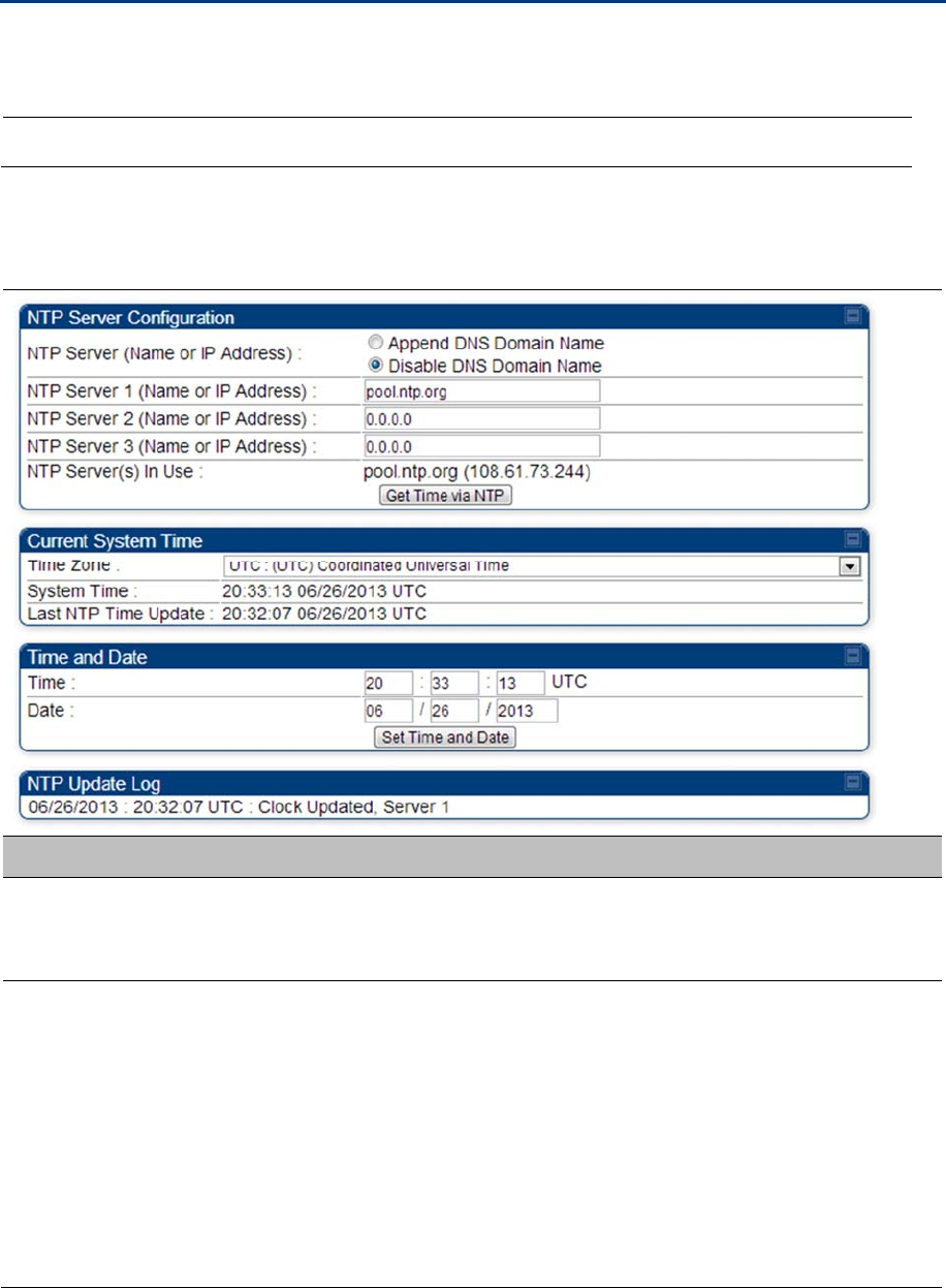
Chapter 7: Configuration Setting up time and date
Page 7-96
Setting up time and date
Time page of 450 Platform Family - AP/BHM
Applicable products PMP :
AP
PTP:
BHM
The Time page of 450 Platform Family AP/BHM is explained in Table 130.
Table 130
450 Platform Family - AP/BHM Time attributes
Attribute Meaning
NTP Server (Name or
IP Address)
The management DNS domain name may be toggled such that the name of
the NTP server only needs to be specified and the DNS domain name is
automatically appended to that name.
NTP Server 1 (Name
or IP Address)
NTP Server 2 (Name
or IP Address)
NTP Server 3 (Name
or IP Address)
To have each log in the AP/BHM correlated to a meaningful time and date,
either a reliable network element must pass time and date to the AP/BHM or
must set the time and date whenever a power cycle of the AP/BHM has
occurred. A network element passes time and date in any of the following
scenarios:
A connected CMM4 passes time and date (GPS time and date, if
received).
A connected CMM4 passes the time and date (GPS time and date, if
received), but only if both the CMMr is operating on CMMr Release 2.1 or
later release. (These releases include NTP server functionality.)

Chapter 7: Configuration Setting up time and date
Page 7-97
A separate NTP server (including APs/BHMs receiving NTP data) is
addressable from the AP/BHM.
If the AP/BHM needs to obtain time and date from a CMM4, or a separate
NTP server, enter the IP address or DNS name of the CMM4 or NTP server
on this tab. To force the AP/BHM to obtain time and date before the first (or
next) 15-minute interval query of the NTP server, click Get Time via NTP.
The polling of the NTP servers is done in a sequential fashion, and the polling
status of each server is displayed in the NTP Update Log section of the Time
Configuration page. An entry of 0.0.0.0 in any of the NTP Server fields
indicates an unused server configuration.
NTP Server(s) in Use Lists the IP addresses of servers used for NTP retrieval.
Time Zone The Time Zone option may be used to offset the received NTP time to match
the operator’s local time zone. When set on the AP/BHM, the offset is set for
the entire sector SMs (or BHS) are notified of the current Time Zone upon
initial registration). If a Time Zone change is applied, the SMs(or BHS) is
notified of the change in a best effort fashion, meaning some SMs//BHSs may
not pick up the change until the next re-registration. Time Zone changes are
noted in the Event Log of the AP/BHM and SM/BHS.
System Time The current time used by the system.
Last NTP Time
Update
The last time that the system time was set via NTP.
Time This field may be used to manually set the system time of the radio.
Date This field may be used to manually set the system date of the radio.
NTP Update Log This field shows NTP clock update log. It includes NTP clock update Date and
Time stamp along with server name.
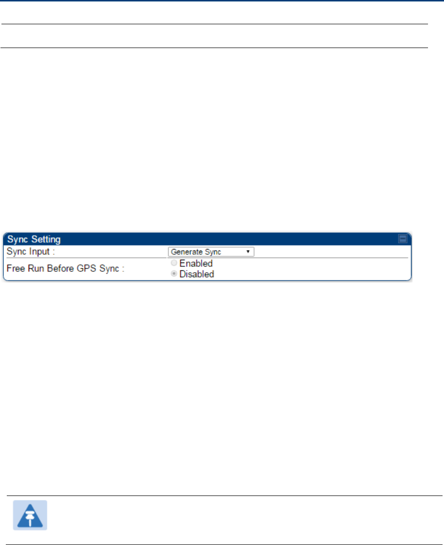
Chapter 7: Configuration Configuring synchronization
Page 7-98
Configuring synchronization
Applicable products PMP : AP PTP: BHM
This section describe synchronization options for PMP and PTP configuration.
This Sync Input parameter can be configured under Sync Setting tab of Configure > General page (see
General configuration on page 7-68).
PMP/PTP 450i Series has following synchronization options:
AutoSync
AutoSync + Free Run
Generate Sync
Free Run Before GPS Sync
Figure 137 Sync Setting configuration
AutoSync
For PTP, the BHM automatically receives sync from one of the following sources:
GPS Sync over Timing Port (UGPS, co-located AP GPS sync output, or “Remote ” Device feed from
a registered SM’s GPS sync output)
GPS Sync over Power Port (CMM4)
Upon AP/BM power on, the AP/BHM does not transmit until a valid synchronization pulse is received from
one of the sources above. If there is a loss of GPS synchronization pulse, within two seconds the
AP/BHM automatically attempts to source GPS signaling from another source.
In case of PMP, when there are synchronization sources on both the timing port and the power port, the
power port GPS source is chosen first.
If no valid GPS signal is received, the AP/BHM ceases transmission and SM/BHS registration is lost until
a valid GPS signal is received again on the AP or BHM.
Note
After an AP reboot, the sync acquisition takes a little longer than it had on 450i (anywhere
from 40 seconds to 120 seconds difference).

Chapter 7: Configuration Configuring synchronization
Page 7-99
AutoSync + Free Run
This mode operates similarly to mode “AutoSync”, but if a previously received synchronization signal is
lost and no GPS signaling alternative is achieved, the AP/BHM automatically changes to synchronization
mode “Generate Sync”. While SM registration ins maintained, in this mode there is no synchronization of
APs/BHMs that can “hear” each other; the AP/BHM will only generate a sync signal for the local AP/BHM
and its associated SMs/BHS. Once a valid GPS signal is obtained again, the AP/BHM automatically
switches to receiving synchronization via the GPS source and SM/BHS registration is maintained.
When the Sync Input field is set to Autosync or Autosync + Free Run, other options become available to
be set e.g. UGPS Power and other fields. This is true on APs and BHMs.
Note
In mode AutoSync + Free Run, if a GPS signal is never achieved initially, the system will
not switch to “Free Run” mode, and SMs/BHS will not register to the AP/BHM. A valid GPS
signal must be present initially for the AP to switch into “Free Run” mode (and to begin
self-generating a synchronization pulse).
Also, When an AP/BHM is operating in “Free Run” mode, over a short time it will no longer
be synchronized with co-located or nearby APs/BHMs (within radio range). Due to this lack
of transmit and receive synchronization across APs/BHMs or across systems, performance
while in “Free Run” mode may be degraded until the APs/BHMs operating in “Free Run”
mode regain a external GPS synchronization source. Careful attention is required to
ensure that all systems are properly receiving an external GPS synchronization pulse, and
please consider “Free Run” mode as an emergency option.
Generate Sync (factory default)
This option may be used when the AP/BHM is not receiving GPS synchronization pulses from either a
CMM4 or UGPS module, and there are no other APs/BHMs active within the link range. Using this option
will not synchronize transmission of APs/BHMs that can “hear” each other; it will only generate a sync
signal for the local AP/BHM and its associated SMs/BHS.
Note
When an AP/BHM has its "Regional Code" set to "None", The radio will not provide valid
Sync Pulse Information.
There is a RED warning that the radio will not transmit, but the user might expect to see a
valid sync if the radio is connected to a working CMM4 or UGPS.

Chapter 7: Configuration Configuring security
Page 7-100
Configuring security
Perform this task to configure the 450 Platform system in accordance with the network operator’s security
policy. Choose from the following procedures:
Managing module access by password on page 7-100: to configure the unit access password and
access level
Isolating from the internet on page 7-103: to ensure that APs are properly secured from external
networks
Encrypting radio transmissions on page 7-103: to configure the unit to operate with AES or DES
wireless link security
Requiring SM Authentication on page 7-104: to set up the AP to require SMs to authenticate via the
AP, WM, or RADIUS server
Filtering protocols and ports on page 7-105: to filter (block) specified protocols and ports from leaving
the system
Encrypting downlink broadcasts on page 7-108: to encrypt downlink broadcast transmissions
Isolating SMs on page 7-108: to prevent SMs in the same sector from directly communicating with
each other
Filtering management through Ethernet on page 7-109: to prevent management access to the SM via
the radio’s Ethernet port
Allowing management only from specified IP addresses on page 7-109: to only allow radio
management interface access from specified IP addresses
Restricting radio Telnet access over the RF interface on page 7-109: to restrict Telnet access to the
AP
Configuring SNMP Access on page 7-112
Configuring Security on page 7-114
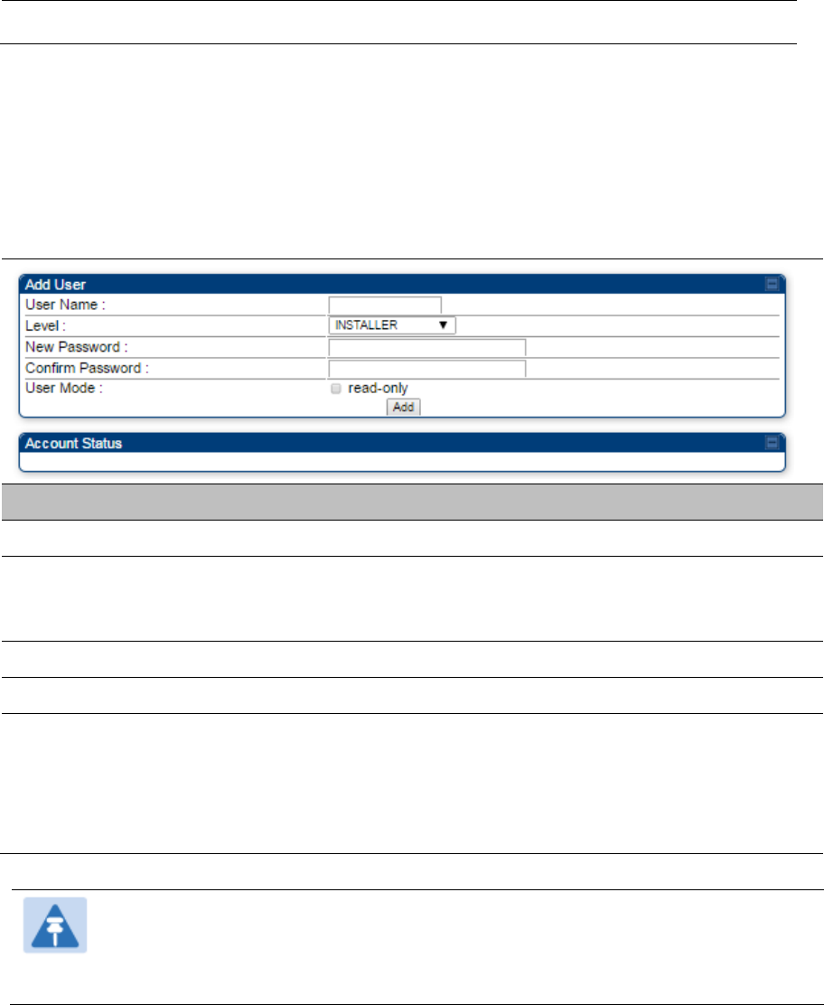
Chapter 7: Configuration Configuring security
Page 7-101
Managing module access by password
Applicable products PMP : AP SM PTP: BHM BMS
See Managing module access by passwords on page 3-44.
Adding a User for Access to a module
The Account > Add User page allows to create a new user for accessing 450 Platform Family -
AP/SM/BHM/BHS. The Add User page is explained in Table 131.
Table 131 Add User page of account page - AP/ SM/BH
Attribute Meaning
User Name User Account name.
Level Select appropriate level for new account. It can be INSTALLER,
ADMINISTRATOR or TECHNICIAN. See Managing module access by
passwords on page 3-44.
New Password Assign the password for new user account
Confirm Password This new password must be confirmed in the “Confirm Password” field.
User Mode User Mode is used to create an account which are mainly used for viewing
the configurations.
The local and remote Read-Only user account can be created by “Admin”,
“Installer” or “Tech” logins. To create a Read-Only user, the “read-only” check
box needs to be checked.
Note
The Read-Only user cannot perform any service impacting operations like creating read-
only accounts, editing and viewing read-only user accounts, changes in login page, read-
only user login, Telnet access, SNMP, RADIUS and upgrade/downgrade.
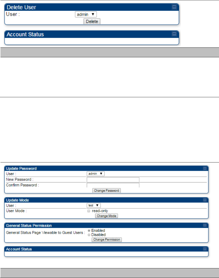
Chapter 7: Configuration Configuring security
Page 7-102
Deleting a User from Access to a module
The Account > Delete User page provides a drop down list of configured users from which to select the
user you want to delete. The Delele User page is explained in Table 132.
Table 132 Delete User page - 450 Platform Family - AP/ SM/BH
Attribute Meaning
User Select a user from drop down list which has to be deleted and click Delete
button.
Accounts that cannot be deleted are
the current user's own account.
the last remaining account of ADMINISTRATOR level.
Changing a User Setting
The Account > Change User Setting page allows to update password, mode update and general status
permission for a user.
From the factory default state, configure passwords for both the root and admin account at the
ADMINISTRATOR permission level, using Update Password tab of Change Users Setting page.
The Change User Setting page is explained in Table 133.
Table 133 Change User Setting page - 450 Platform Family AP/ SM/BH
Attribute Meaning
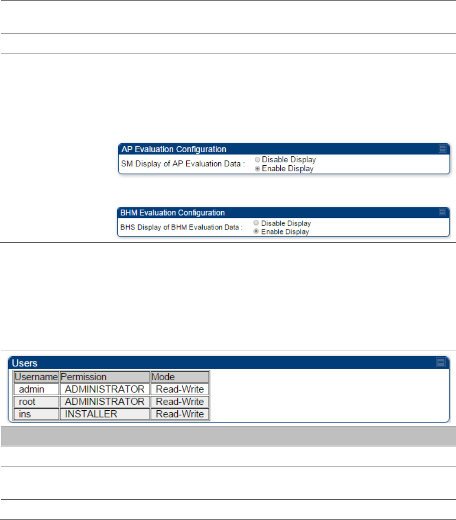
Chapter 7: Configuration Configuring security
Page 7-103
Update Password tab This tab provides a drop down list of configured users from which a user is
selected to change password.
Update Mode tab This tab facilitates to convert a configured user to a Read-Only user.
General Status
Permission tab
This tab enables and disables visibility of General Status Page for all Guest
user.
To display of Radio data on SMs/BHS main Login page for Guest login, it can
be enabled or disabled in Security tab of Configuration page.
Figure 138 AP Evaluation Configuration parameter of Security tab for PMP
Figure 139 BHM Evaluation Configuration parameter of Security tab for PTP
Users account
The Account > Users page allows to view all configured users account for accessing the module.
The Users page is explained in Table 134.
Table 134 User page –450 Platform Family AP/SM/BH
Attribute Meaning
Username User access account name
Permission Permission of configured user – INSTALLER, ADMINISTRATOR or
TECHNICIAN
Mode This field indicate access mode of user – Read-Write or Read-Only.

Chapter 7: Configuration Configuring security
Page 7-104
Overriding Forgotten IP Addresses or Passwords on AP and
SM
See Radio recovery mode on page 1-26
Isolating from the internet – APs/BHMs
Applicable products PMP : AP PTP: BHM
See Isolating AP/BHM from the Internet on page 3-42.
Encrypting radio transmissions
Applicable products PMP : AP SM PTP: BHM BMS
See Encrypting radio transmissions on page 3-42.

Chapter 7: Configuration Configuring security
Page 7-105
Requiring SM Authentication
Applicable products PMP : AP SM
Through the use of a shared AP key, or an external RADIUS (Remote Authentication Dial In User
Service) server, it enhances network security by requiring SMs to authenticate when they register.
For descriptions of each of the configurable security parameters on the AP, see Configuring Security on
page 7-114. For descriptions of each of the configurable security parameters on the SM, see Security on
page 7-119.
Operators may use the AP’s Authentication Mode field to select from among the following authentication
modes:
Disabled—the AP requires no SMs to authenticate (factory default setting).
Authentication Server —the AP requires any SM that attempts registration to be authenticated in
Wireless Manager before registration
AP PreShared Key - The AP acts as the authentication server to its SMs and will make use of a
user-configurable pre-shared authentication key. The operator enters this key on both the AP and all
SMs desired to register to that AP. There is also an option of leaving the AP and SMs at their default
setting of using the “Default Key”. Due to the nature of the authentication operation, if you want to set
a specific authentication key, then you MUST configure the key on all of the SMs and reboot them
BEFORE enabling the key and option on the AP. Otherwise, if you configure the AP first, none of the
SMs is able to register.
RADIUS AAA - When RADIUS AAA is selected, up to 3 Authentication Server (RADIUS Server) IP
addresses and Shared Secrets can be configured. The IP address(s) configured here must match the
IP address(s) of the RADIUS server(s). The shared secret(s) configured here must match the shared
secret(s) configured in the RADIUS server(s). Servers 2 and 3 are meant for backup and reliability,
not for splitting the database. If Server 1 doesn’t respond, Server 2 is tried, and then server 3. If
Server 1 rejects authentication, the SM is denied entry to the network, and does not progress trying
the other servers.
For more information on configuring the PMP 450 Platform network to utilize a RADIUS server, see
Configuring a RADIUS server on page 7-226.
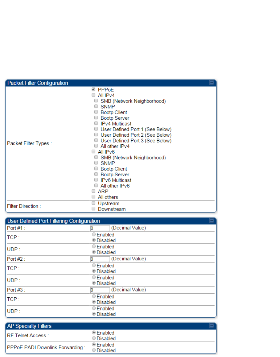
Chapter 7: Configuration Configuring security
Page 7-106
Filtering protocols and ports
Applicable products PMP : AP SM PTP: BHM BMS
The filtering protocols and ports allows to configure filters for specified protocols and ports from leaving
the AP/SM/BHM/BHS and entering the network. See Filtering protocols and ports on page 3-45.
Protocol filtering page of 450 Platform Family AP/BHM
The Protocol Filtering page of 450 Platform Family - AP/BHM is explained in Table 135.
Table 135 AP/BHM Protocol Filtering attributes

Chapter 7: Configuration Configuring security
Page 7-107
Attribute Meaning
Packet Filter Types
For any box selected, the Protocol and Port Filtering feature blocks the
associated protocol type.
To filter packets in any of the user-defined ports, must do all of the following:
Check the box for User Defined Port n (See Below) in the Packet Filter
Types section of this tab.
In the User Defined Port Filtering Configuration section of this tab:
provide a port number at Port #n.
enable TCP and/or UDP by clicking the associated radio button
Filter Direction Operators may choose to filter upstream (uplink) RF packets or downstream
(downlink) RF packets.
User Defined Port
Filtering Configuration
You can specify ports for which to block subscriber access, regardless of
whether NAT is enabled.
RF Telnet Access RF Telnet Access restricts Telnet access to the AP/BHM from a device
situated below a network SM/BHS (downstream from the AP/BHM). This is a
security enhancement to restrict RF-interface sourced AP access specifically
to the LAN1 IP address and LAN2 IP address (Radio Private Address,
typically 192.168.101.[LUID]). This restriction disallows unauthorized users
from running Telnet commands on the AP/BHM that can change AP/BHM
configuration or modifying network-critical components such as routing and
ARP tables.
PPPoE PADI
Downlink Forwarding
Enabled: the AP/BHM allows downstream and upstream transmission of
PPPoE PADI packets. By default, PPPoE PADI Downlink Forwarding is set to
“Enabled”.
Disabled: the AP/BHM disallows PPPoE PADI packets from entering the
Ethernet interface and exiting the RF interface (downstream to the SM/BHS).
PPPoE PADI packets are still allowed to enter the AP’s RF interface and exit
the AP’s /BHM’s Ethernet interface (upstream).
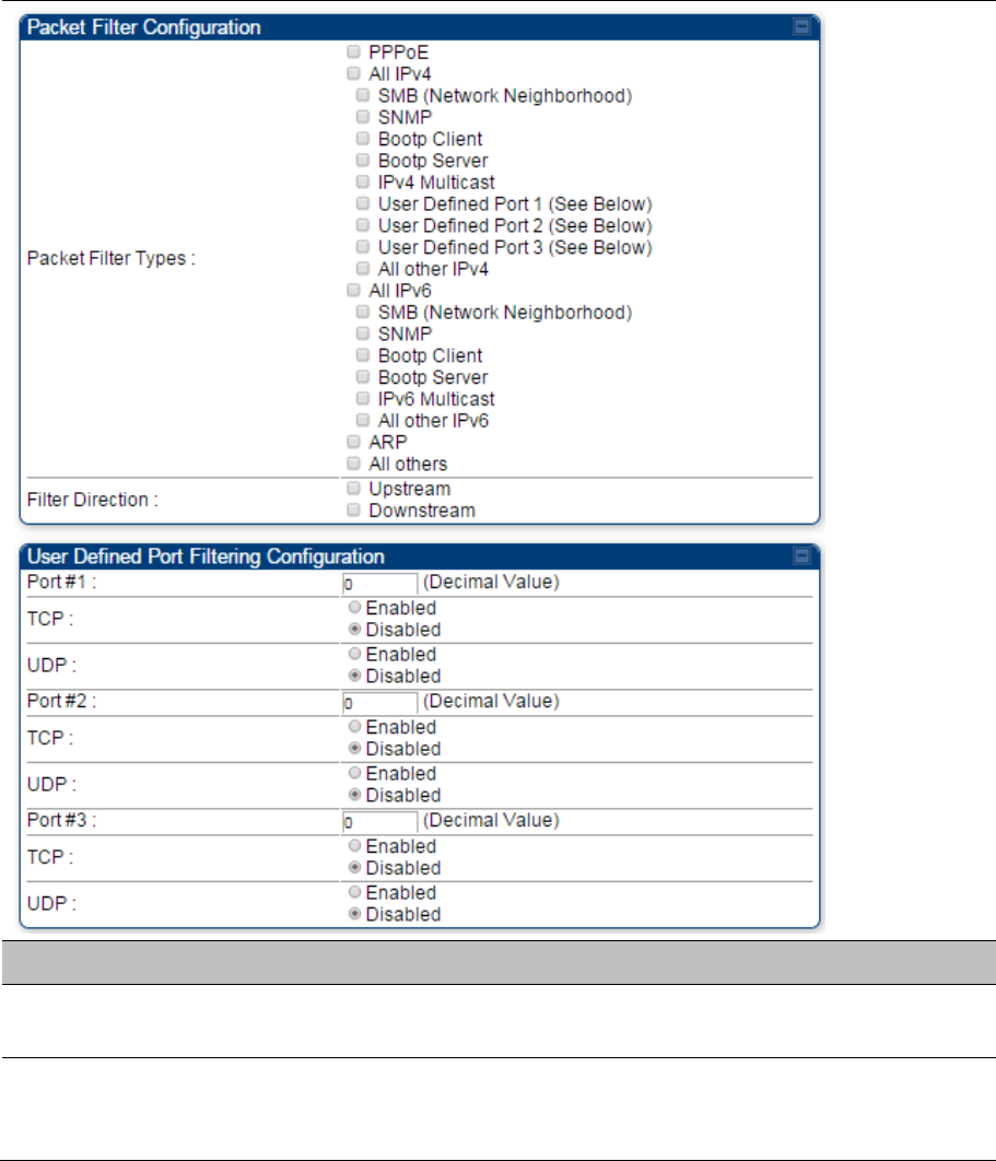
Chapter 7: Configuration Configuring security
Page 7-108
Protocol filtering page of SM/BHS
The Protocol Filtering page of SM/BHS is explained in Table 136.
Table 136 SM/BHS Protocol Filtering attributes
Attribute Meaning
Packet Filter
Configuration tab
See Table 135 AP/BHM Protocol Filtering attributes on page 7-105
User Defined Port
Filtering
Configuration tab
See Table 135 AP/BHM Protocol Filtering attributes on page 7-105
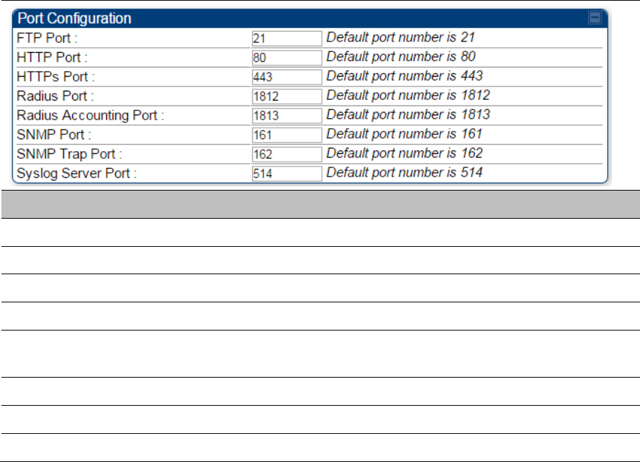
Chapter 7: Configuration Configuring security
Page 7-109
Port configuration
450 Platform Family ODUs support access to various communication protocols and only the ports
required for these protocols are available for access by external entities. Operators may change the port
numbers for these protocols via the radio GUI or SNMP.
The Port Configuration page of the AP/SM/BHM/BHS is explained in Table 137.
Table 137 Port Configuration attributes – AP/SM/BHM/BMS
Attribute Meaning
FTP Port The listen port on the device used for FTP communication.
HTTP Port The listen port on the device used for HTTP communication.
HTTPS Port The listen port on the device used for HTTPS communication
Radius Port The destination port used by the device for RADIUS communication.
Radius Accounting
Port
The destination port used by the device for RADIUS accounting
communication.
SNMP Port The listen port on the device used for SNMP communication.
SNMP Trap Port The destination port used by the device to which SNMP traps are sent.
Syslog Server Port The destination port used by the device to which Syslog messaging is sent.
Encrypting downlink broadcasts
See Encrypting downlink broadcasts on page 3-49.
Isolating SMs
See Isolating SMs in PMP on page 3-49.
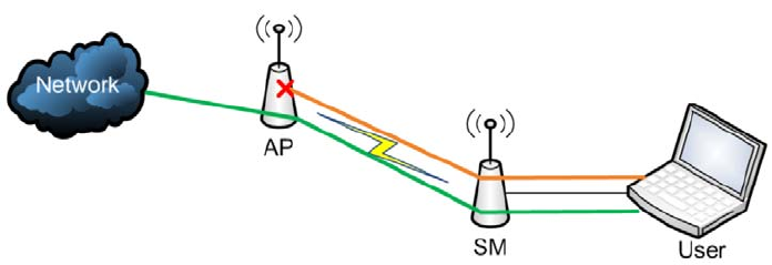
Chapter 7: Configuration Configuring security
Page 7-110
Filtering management through Ethernet
See Filtering management through Ethernet on page 3-49.
Allowing management only from specified IP
addresses
See Allowing management from only specified IP addresses on page 3-50.
Restricting radio Telnet access over the RF interface
RF Telnet Access restricts Telnet access to the AP from a device situated below a network SM
(downstream from the AP). This is a security enhancement to restrict RF-interface sourced AP access
specifically to the LAN1 IP address and LAN2 IP address (Radio Private Address, typically 192.168.101.
[LUID]). This restriction disallows unauthorized users from running Telnet commands on the AP that can
change AP configuration or modifying network-critical components such as routing and ARP tables.
The RF Telnet Access may be configured via the AP GUI or via SNMP commands, and RF Telnet Access
is set to “Enabled” by default. Once RF Telnet Access is set to “Disabled”, if there is a Telnet session
attempt to the AP originating from a device situated below the SM (or any downstream device), the
attempt is dropped. This also includes Telnet session attempts originated from the SM’s management
interface (if a user has initiated a Telnet session to a SM and attempts to Telnet from the SM to the AP).
In addition, if there are any active Telnet connections to the AP originating from a device situated below
the SM (or any downstream device), the connection is dropped. This behavior must be considered if
system administrators use Telnet downstream from an AP (from a registered SM) to modify system
parameters.
Setting RF Telnet Access to “Disabled” does not affect devices situated above the AP from accessing the
AP via Telnet, including servers running the CNUT (Canopy Network Updater tool) application. Also,
setting RF Telnet Access to “Disabled” does not affect any Telnet access into upstream devices (situated
above or adjacent to the AP) through the AP (see Figure 140).
The figure below depicts a user attempting two telnet sessions. One is targeted for the AP (orange) and
one is targeted for the network upstream from the AP (green). If RF Telnet Access is set to “Disabled”
(factory default setting), the Telnet attempt from the user to the AP is blocked, but the attempt from the
user to Network is allowed to pass through the Cambium network.
Figure 140 RF Telnet Access Restrictions (orange) and Flow through (green)
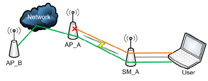
Chapter 7: Configuration Configuring security
Page 7-111
Key Security Considerations when using the RF Telnet
Access Feature
To ensure that the network is fully protected from unauthorized AP Telnet sessions, the following topics
must be considered:
Securing AP Clusters
When working with a cluster of AP units, to eliminate potential security holes allowing Telnet access,
ensure that the RF Telnet Access parameter is set to “Disabled” for every AP in the cluster. In addition,
since users situated below the AP are able to pass Telnet sessions up through the SM and AP to the
upstream network (while AP RF Telnet Access is set to “Disabled”), ensure that all CMM4 or other
networking equipment is secured with strong passwords. Otherwise, users may Telnet to the CMM4 or
other networking equipment, and subsequently access network APs (see Figure 141) via their Ethernet
interfaces (since RF Telnet Access only prevents Telnet sessions originating from the AP’s wireless
interface).
Figure 141 RF Telnet Access Restriction (orange) and Potential Security Hole (green)
As a common practice, AP administrator usernames and passwords must be secured with strong, non-
default passwords.
Restricting AP RF Telnet Access
AP Telnet access via the RF interface may be configured in two ways – the AP GUI and SNMP.
Controlling RF Telnet Access via the AP GUI
To restrict all Telnet access to the AP via the RF interface from downstream devices, follow these
instructions using the AP GUI:
Procedure 20 Restricting RF Telnet access
1 Log into the AP GUI using administrator credentials
2 On the AP GUI, navigate to Configuration > Protocol Filtering
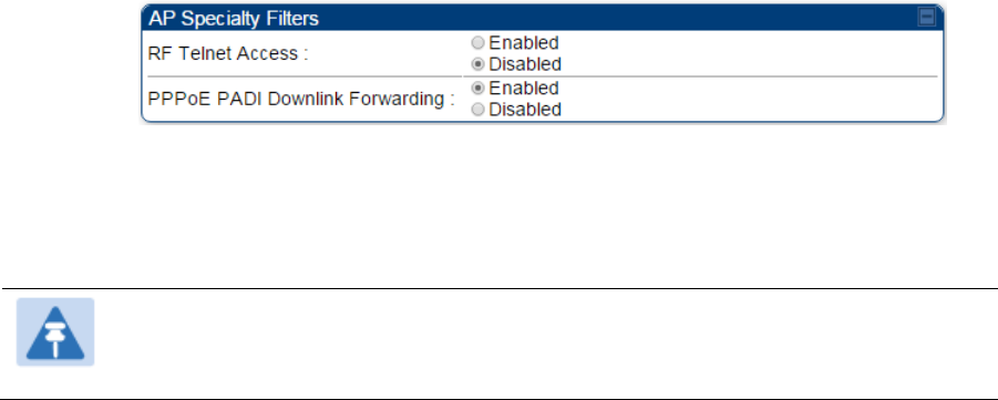
Chapter 7: Configuration Configuring security
Page 7-112
3 Under GUI heading “Telnet Access over RF Interface”, set RF Telnet Access to Disabled
4 Click the Save button
5 Once the Save button is clicked, all RF Telnet Access to the AP from devices situated below
the AP is blocked.
Note
The factory default setting for RF Telnet Access is disabled and PPPoE PADI Downlink
Forwarding is enabled.
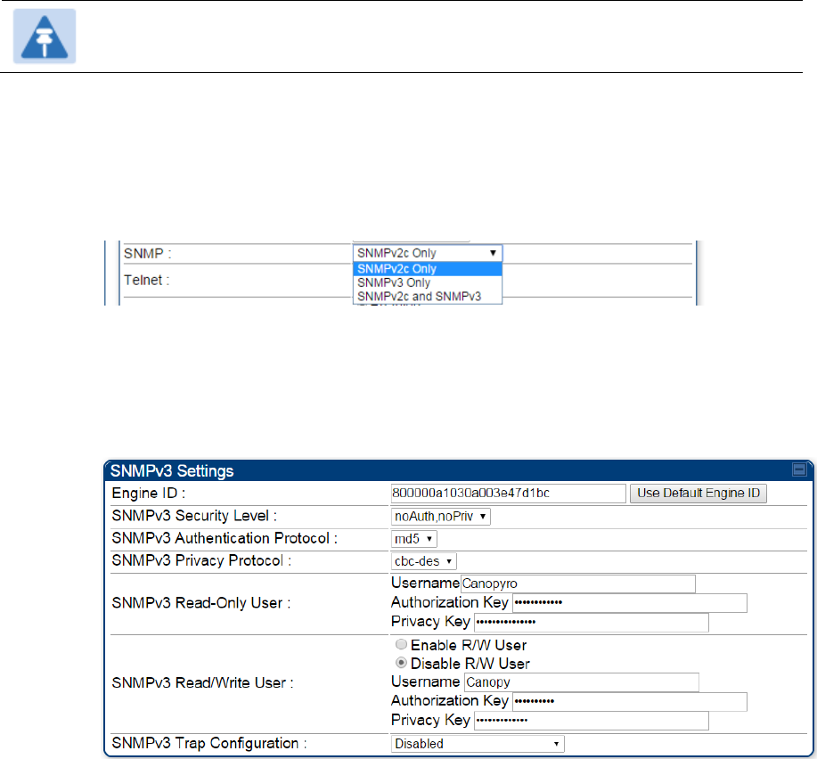
Chapter 7: Configuration Configuring security
Page 7-113
Configuring SNMP Access
The SNMPv3 interface provides a more secure method to perform SNMP operations. This standard
provides services for authentication, data integrity and message encryption over SNMP. Refer to
Planning for SNMPv3 operation on page 3-43 for details.
Note
The factory default setting for SNMP is “SNMPv2c Only”.
Procedure 21 Configuring SNMPv3
1 Log into the AP GUI using administrator credentials
2 On the AP/SM GUI, navigate to Configuration > Security Page
3 Under GUI heading “Security Mode”, set SNMP to SNMPv3 Only
4 Click the Save Changes button
5 Go to Configuration > SNMP Page
6 Under GUI heading “SNMPv3 setting”, set Engine ID, SNMPv3 Security Level, SNMPv3
Authentication Protocol, SNMPv3 Privacy Protocol, SNMPv3 Read-Only User, SNMPv3
Read/Write User, SNMPv3 Trap Configuration parameters:
Engine ID :
Each radio (AP/SM/BHM/BHS) has a distinct SNMP authoritative engine identified by a
unique Engine ID. While the Engine ID is configurable to the operator it is expected that the
operator follow the guidelines of the SNMPEngineID defined in the SNMP-FRAMEWORK-
MIB (RFC 3411). The default Engine ID is the MAC address of the device.
SNMPv3 security level, Authentication and Privacy Protocol
The authentication allows authentication of SNMPv3 user and privacy allows for encryption of
SNMPv3 message. 450 Platform Family supports MD5 authentication and CBC-DES privacy
protocols.

Chapter 7: Configuration Configuring security
Page 7-114
SNMPv3 Read-Only and Read/Write User
The user can defined by configurable attributes. The attributes and default values are:
Read-only user
o Username = Canopyro
o Authentication Password = authCanopyro
o Privacy Password = privacyCanopyro
Read-write user (by default read-write user is disabled)
o Username = Canopy
o Authentication Password = authCanopy
o Privacy Password = privacyCanopy
SNMPv3 Trap Configuration
The traps may be sent from radios in SNMPv3 format based on parameter settings. It can be
configured for Disabled, Enabled for Read-Only User, Enable for Read/Write User.
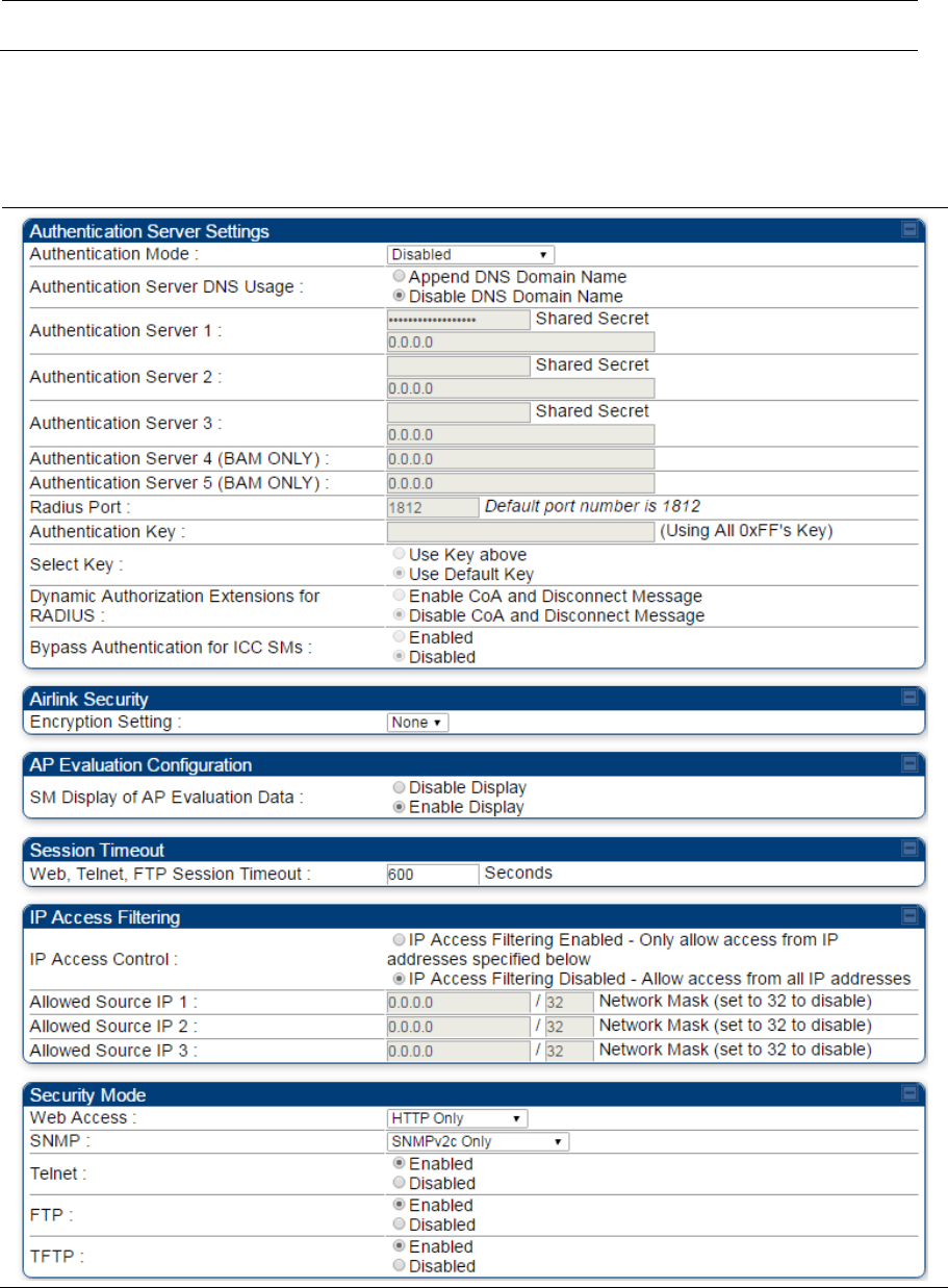
Chapter 7: Configuration Configuring security
Page 7-115
Configuring Security
Applicable products PMP : AP SM PTP: BHM BMS
Security page – 450 Platform Family AP/BHM
The security page of AP/BHM is explained in Table 138.
Table 138 Security attributes –450 Platform Family AP
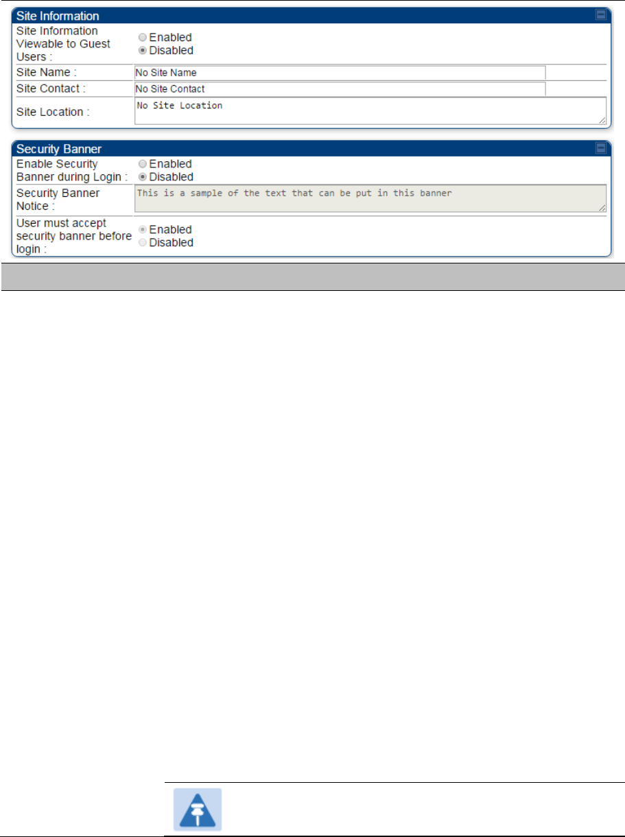
Chapter 7: Configuration Configuring security
Page 7-116
Attribute Meaning
Authentication Mode Operators may use this field to select from among the following authentication
modes:
Disabled—the AP/BHM requires no SMs/BHS to authenticate. (Factory
default).
Authentication Server —the AP/BHM requires any SM/BHS that attempts
registration to be authenticated in Wireless Manager before registration.
AP PreShared Key - The AP/BHM acts as the authentication server to its
SMs/BHS and will make use of a user-configurable pre-shared authentication
key. The operator enters this key on both the AP/BHM and all SMs/BHS
desired to register to that AP/BHM. There is also an option of leaving the
AP/BHM and SMs/BHS at their default setting of using the “Default Key”. Due
to the nature of the authentication operation, if you want to set a specific
authentication key, then you MUST configure the key on all of the SMs/BHS
and reboot them BEFORE enabling the key and option on the AP/BHM.
Otherwise, if you configure the AP/BHM first, none of the SMs/BHS is able to
register.
RADIUS AAA - When RADIUS AAA is selected, up to 3 Authentication
Server (RADIUS Server) IP addresses and Shared Secrets can be
configured. The IP address(s) configured here must match the IP address(s)
of the RADIUS server(s). The shared secret(s) configured here must match
the shared secret(s) configured in the RADIUS server(s). Servers 2 and 3
are meant for backup and reliability, not for splitting the database. If Server 1
doesn’t respond, Server 2 is tried, and then server 3. If Server 1 rejects
authentication, the SM is denied entry to the network, and does not progress
trying the other servers.
Note
This parameter is applicable to BHM.
Chapter 7: Configuration Configuring security
Page 7-117
Authentication Server
DNS Usage
The management DNS domain name may be toggled such that the name of
the authentication server only needs to be specified and the DNS domain
name is automatically appended to that name.
Note
This parameter is applicable to BHM.
Authentication Server
1 to 5
Enter the IP address or server name of the authentication server (RADIUS or
WM) and the Shared Secret configured in the authentication server. When
Authentication Mode RADIUS AAA is selected, the default value of Shared
Secret is “CanopySharedSecret”. The Shared Secret may consist of up to 32
ASCII characters.
Note
This parameter is applicable to BHM.
Radius Port This field allows the operator to configure a custom port for RADIUS server
communication. The default value is 1812.
Note
This parameter is applicable to BHM.
Authentication Key The authentication key is a 32-character hexadecimal string used when
Authentication Mode is set to AP PreShared Key. By default, this key is set
to 0xFFFFFFFFFFFFFFFFFFFFFFFFFFFFFFFF.
Note
This parameter is applicable to BHM.
Select Key
This option allows operators to choose which authentication key is used:
Use Key above means that the key specified in Authentication Key is used
for authentication
Use Default Key means that a default key (based off of the SM’s MAC
address) is used for authentication
Note
This parameter is applicable to BHM.
Dynamic Authorization
Extensions for
RADIUS
Enable CoA and Disconnect Message: Allows to control configuration
parameters of SM using RADIUS CoA and Disconnect Message feature.
Disable CoA and Disconnect Message: Disables RADIUS CoA and
Disconnect Message feature.
To enable CoA and Disconnect feature, the Authentication Mode should be
set to RADIUS AAA.
Bypass Authentication
for ICC SMs
Enabled: SM authentication is disabled when SM connects via ICC
(Installation Color Code).
Disabled: SM authentication is enabled.
Encryption Setting Specify the type of airlink security to apply to this AP. The encryption setting
must match the encryption setting of the SMs.
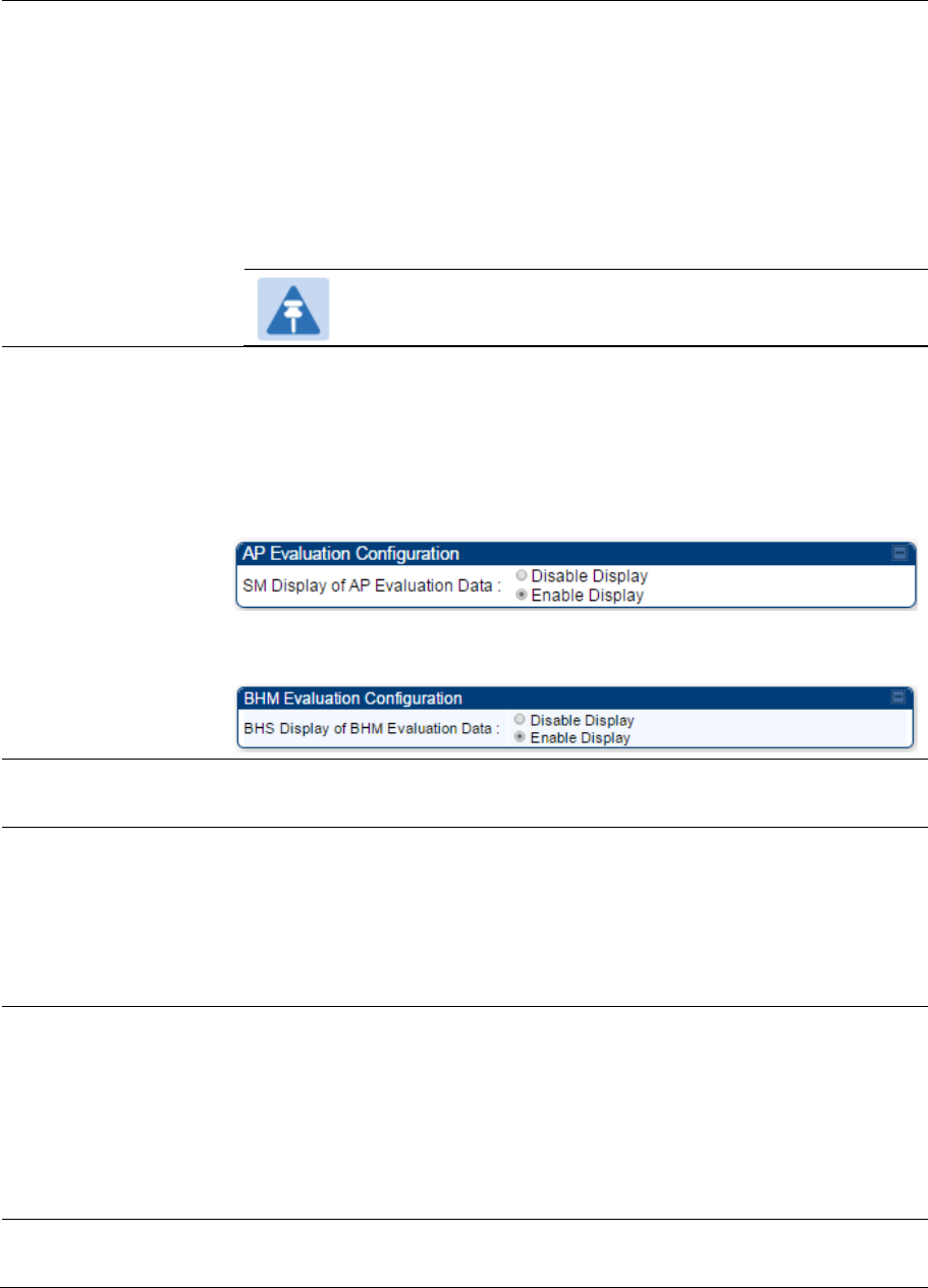
Chapter 7: Configuration Configuring security
Page 7-118
None provides no encryption on the air link.
DES (Data Encryption Standard): An over-the-air link encryption option that
uses secret 56-bit keys and 8 parity bits. DES performs a series of bit
permutations, substitutions, and recombination operations on blocks of data.
DES encryption does not affect the performance or throughput of the system.
AES (Advanced Encryption Standard): An over-the-air link encryption option
that uses the Rijndael algorithm and 128-bit keys to establish a higher level of
security than DES. AES products are certified as compliant with the Federal
Information Processing Standards (FIPS 197) in the U.S.A.
Note
This parameter is applicable to BHM.
SM Display of AP
Evaluation Data
Or
BHS Display of BHM
Evaluation Data
Allows operators to suppress the display of data about this AP/BHM on the
AP/BHM Evaluation tab of the Tools page in all SMs/BHS that register. The
factory default setting for SM Display of AP Evaluation Data or BHS Display
of BHM Evaluation Data is enabled display.
PMP 450/450i Series – SM display of AP Evaluation Data parameter
PTP 450/450i Series – BHS display of BHM Evaluation Data parameter
Web, Telnet, FTP
Session Timeout
Enter the expiry in seconds for remote management sessions via HTTP,
telnet, or ftp access to the AP/BHM.
IP Access Control You can permit access to the AP/BHM from any IP address (IP Access
Filtering Disabled) or limit it to access from only one, two, or three IP
addresses that you specify (IP Access Filtering Enabled). If you select IP
Access Filtering Enabled, then you must populate at least one of the three
Allowed Source IP parameters or have no access permitted from any IP
address
Allowed Source IP 1
to 3
If you selected IP Access Filtering Enabled for the IP Access Control
parameter, then you must populate at least one of the three Allowed Source
IP parameters or have no access permitted to the AP from any IP address.
You may populate as many as all three.
If you selected IP Access Filtering Disabled for the IP Access Control
parameter, then no entries in this parameter are read, and access from all IP
addresses is permitted.
Web Access The Radio supports secured and non-secured web access protocols. Select
suitable web access from drop down list:

Chapter 7: Configuration Configuring security
Page 7-119
HTTP Only – provides non-secured web access. The radio to be
accessed via http://<IP of Radio>.
HTTPS Only – provides a secured web access. The radio to be accessed
via https://<IP of Radio>.
HTTP and HTTPS – If enabled, the radio can be accessed via both http
and https.
SNMP This option allows to configure SNMP agent communication version. It can be
selected from drop down list :
SNMPv2c Only – Enables SNMP v2 community protocol.
SNMPv3 Only – Enables SNMP v3 protocol. It is a secured
communication protocol.
SNMPv2c and SNMPv3 – It enables both the protocols.
Telnet This option allows to Enable and Disable Telnet access to the Radio.
FTP This option allows to Enable and Disable FTP access to the Radio.
TFTP This option allows to Enable and Disable TFTP access to the Radio.
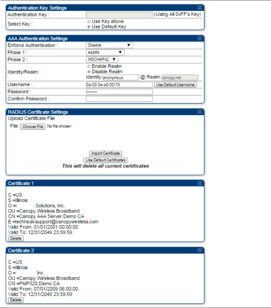
Chapter 7: Configuration Configuring security
Page 7-120
Security page - 450 Platform Family SM
The security page of 450 Platform Family SM is explained in Table 139.
Table 139 Security attributes –450 Platform Family SM
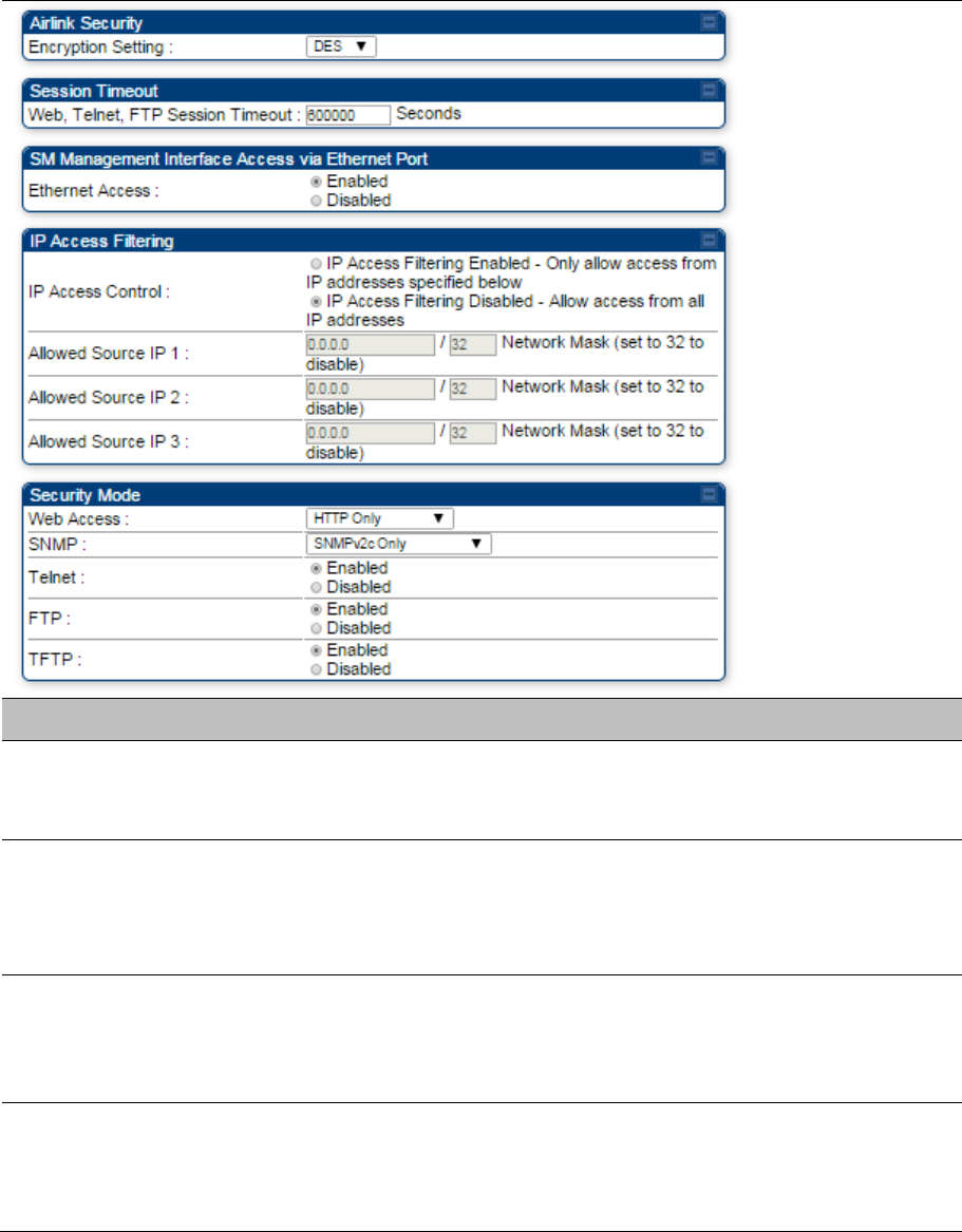
Chapter 7: Configuration Configuring security
Page 7-121
Attribute Meaning
Authentication Key Only if the AP to which this SM will register requires authentication, specify
the key that the SM will use when authenticating. For alpha characters in this
hex key, use only upper case.
Select Key
The Use Default Key selection specifies the predetermined key for
authentication in Wireless Manager
The Use Key above selection specifies the 32-digit hexadecimal key that is
permanently stored on both the SM and the WM
Enforce Authentication The SM may enforce authentication types of AAA and AP Pre-sharedKey.
The SM will not finish the registration process if the AP is not using the
configured authentication method (and the SM locks out the AP for 15
minutes).
Phase 1 The protocols supported for the Phase 1 (Outside Identity) phase of
authentication are
EAPTTLS (Extensible Authentication Protocol Tunneled
Transport Layer
Security) or MSCHAPv2 (Microsoft Challenge-Handshake
Authentication Protocol version 2).

Chapter 7: Configuration Configuring security
Page 7-122
Phase 2 Select the desired Phase 2 (Inside Identity) authentication protocol from the
Phase 2 options
of
PAP (Password Authentication Protocol), CHAP
(Challenge Handshake
Authentication
Protocol), and MSCHAP (Microsoft’s
version of CHAP, version 2 is used). The protocol
must
be
consistent with
the authentication protocol configured on the RADIUS
server.
Identity/Realm If Realms are being used, select Enable Realm and configure an outer
identity in the
Identity
field and a Realm in the Realm field. These must
match the Phase 1/Outer Identity and
Realm
configured in the RADIUS
server. The default Identity is “anonymous”. The Identity can be
up
to
128
non-special (no diacritical markings) alphanumeric characters. The default
Realm
is
“canopy.net”. The Realm can also be up to 128 non-special
alphanumeric
characters.
Configure an outer Identity in the Username field. This must match the
Phase
1/Outer
Identity username configured in the RADIUS server. The
default Phase 1/Outer
Identity
Username is “anonymous”. The Username
can be up to 128 non-special (no
diacritical
markings) alphanumeric
characters.
Username Enter a Username for the SM. This must match the username configured
for the SM on
the
RADIUS server. The default Username is the SM’s MAC
address. The Username can be up
to
128 non-special (no diacritical
markings) alphanumeric
characters.
Password Enter the desired password for the SM in the Password and Confirm
Password fields.
The
Password must match the password configured for
the SM on the RADIUS server.
The
default Password is “password”. The
Password can be up to 128 non-special (no
diacritical
markings)
alphanumeric
characters
Upload Certificate File To upload a certificate manually to a SM, first load it in a known place on
your PC
or
network
drive, then click on a Delete button on one of the
Certificate description blocks
to
delete a certificate to provide space for your
certificate. Click on Choose File, browse to
the
location of the certificate,
and click the Import Certificate button, and then reboot the radio
to
use the
new certificate.
When a certificate is in use, after the SM successfully registers to an AP, an
indication of In
Use
will appear in the description block of the certificate
being
used.
The public certificates installed on the SMs are used with the private
certificate on the
RADIUS
server to provide a public/private key encryption
system.
Up to 2 certificates can be resident on a SM. An installed certificate can be
deleted
by
clicking the Delete button in the certificate’s description block on
the Configuration >
Security
tab. To restore the 2 default certificates, click
the Use Default Certificates button in
the
RADIUS Certificate Settings
parameter block and reboot the
radio.
Chapter 7: Configuration Configuring security
Page 7-123
Encryption Setting Specify the type of airlink security to apply to this SM. The encryption setting
must match the encryption setting of the AP.
None provides no encryption on the air link.
DES (Data Encryption Standard): An over-the-air link encryption option that
uses secret 56-bit keys and 8 parity bits. DES performs a series of bit
permutations, substitutions, and recombination operations on blocks of data.
DES encryption does not affect the performance or throughput of the system.
AES (Advanced Encryption Standard): An over-the-air link encryption option
that uses the Rijndael algorithm and 128-bit keys to establish a higher level of
security than DES. AES products are certified as compliant with the Federal
Information Processing Standards (FIPS 197) in the U.S.A.
Web, Telnet, FTP
Session Timeout
Enter the expiry in seconds for remote management sessions via HTTP,
telnet, or FTP access to the SM.
Ethernet Access
If you want to prevent any device that is connected to the Ethernet port of the
SM from accessing the management interface of the SM, select Ethernet
Access Disabled. This selection disables access through this port to via
HTTP (the GUI), SNMP, telnet, FTP, and TFTP. With this selection,
management access is available through only the RF interface via either an
IP address (if Network Accessibility is set to Public on the SM) or the
Session Status or Remote Subscribers tab of the AP.
Note
This setting does not prevent a device connected to the Ethernet
port from accessing the management interface of other SMs in
the network. To prevent this, use the IP Access Filtering Enabled
selection in the IP Access Control parameter of the SMs in the
network. See IP Access Control below.
If you want to allow management access through the Ethernet port, select
Ethernet Access Enabled. This is the factory default setting for this
parameter.
IP Access Control You can permit access to the SM from any IP address (IP Access Filtering
Disabled) or limit it to access from only one, two, or three IP addresses that
you specify (IP Access Filtering Enabled). If you select IP Access Filtering
Enabled, then you must populate at least one of the three Allowed Source
IP parameters or have no access permitted from any IP address
Allowed Source IP 1
to 3
If you selected IP Access Filtering Enabled for the IP Access Control
parameter, then you must populate at least one of the three Allowed Source
IP parameters or have no access permitted to the SM from any IP address.
You may populate as many as all three.
If you selected IP Access Filtering Disabled for the IP Access Control
parameter, then no entries in this parameter are read, and access from all IP
addresses is permitted.
A subnet mask may be defined for each entry to allow for filtering control
based on a range of IP addresses.

Chapter 7: Configuration Configuring security
Page 7-124
Web Access The Radio supports secured and non-secured web access protocols. Select
suitable web access from drop down list:
HTTP Only – provides non-secured web access. The radio to be
accessed via http://<IP of Radio>.
HTTPS Only – provides a secured web access. The radio to be accessed
via https://<IP of Radio>.
HTTP and HTTPS – If enabled, the radio can be accessed via both http
and https.
SNMP This option allows to configure SNMP agent communication version. It can be
selected from drop down list :
SNMPv2c Only – Enables SNMP v2 community protocol.
SNMPv3 Only – Enables SNMP v3 protocol. It is secured communication
protocol.
SNMPv2c and SNMPv3 – It enables both the protocols.
Telnet This option allows to Enable and Disable Telnet access to the Radio.
FTP This option allows to Enable and Disable FTP access to the Radio.
TFTP This option allows to Enable and Disable TFTP access to the Radio.
Site Name Specify a string to associate with the physical module.
Site Contact Enter contact information for the module administrator.
Site Location Enter information about the physical location of the module.
Enable Security
Banner during Login
Enable: The Security Banner Notice will be displayed before login.
Disable: The Security Banner Notice will not be displayed before login.
Security Banner
Notice
User can enter ASCII (0-9a-zA-Z newline, line-feed are allowed) text up-to
1300 characters.
User must accept
security banner before
login
Enable: login area (username and password) will be disabled unless user
accepts the security banner.
Disable: User can’t login to radio without accepting security banner.
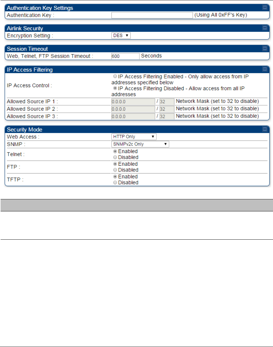
Chapter 7: Configuration Configuring security
Page 7-125
Security page –450 Platform Family BHS
The Security page of 450 Platform Family BHS is explained in Table 140.
Table 140 Security attributes - 450 Platform Family BHS
Attribute Meaning
Authentication Key Only if the BHM to which this BHS registers requires an authentication,
specify the key that the BHS will use when authenticating. For alpha
characters in this hex key, use only upper case.
Encryption Setting Specify the type of airlink security to apply to this BHS. The encryption setting
must match the encryption setting of the BHM.
None provides no encryption on the air link.
DES (Data Encryption Standard): An over-the-air link encryption option that
uses secret 56-bit keys and 8 parity bits. DES performs a series of bit
permutations, substitutions, and recombination operations on blocks of data.
DES encryption does not affect the performance or throughput of the system.
It is factory default setting.
AES (Advanced Encryption Standard): An over-the-air link encryption option
that uses the Rijndael algorithm and 128-bit keys to establish a higher level of
security than DES. AES products are certified as compliant with the Federal
Information Processing Standards (FIPS 197) in the U.S.A.

Chapter 7: Configuration Configuring security
Page 7-126
Web, Telnet, FTP
Session Timeout
Enter the expiry in seconds for remote management sessions via HTTP,
telnet, or FTP access to the BHS.
IP Access Control You can permit access to the BHS from any IP address (IP Access Filtering
Disabled) or limit it to access from only one, two, or three IP addresses that
you specify (IP Access Filtering Enabled). If you select IP Access
Filtering Enabled, then you must populate at least one of the three Allowed
Source IP parameters or have no access permitted from any IP address
Allowed Source IP 1
to 3
If you selected IP Access Filtering Enabled for the IP Access Control
parameter, then you must populate at least one of the three Allowed Source
IP parameters or have no access permitted to the BHS from any IP address.
You may populate as many as all three.
If you selected IP Access Filtering Disabled for the IP Access Control
parameter, then no entries in this parameter are read, and access from all IP
addresses is permitted.
A subnet mask may be defined for each entry to allow for filtering control
based on a range of IP addresses.
Web Access The Radio supports secured and non-secured web access protocols. Select
suitable web access from drop down list:
HTTP Only – provides non-secured web access. The radio to be
accessed via http://<IP of Radio>.
HTTPS Only – provides a secured web access. The radio to be accessed
via https://<IP of Radio>.
HTTP and HTTPS – If enabled, the radio can be accessed via both http
and https.
SNMP This option allows to configure SNMP agent communication version. It can be
selected from drop down list :
SNMPv2c Only – Enables SNMP v2 community protocol.
SNMPv3 Only – Enables SNMP v3 protocol. It is secured communication
protocol.
SNMPv2c and SNMPv3 – It enables both the protocols.
Telnet This option allows to Enable and Disable Telnet access to the Radio.
FTP This option allows to Enable and Disable FTP access to the Radio.
TFTP This option allows to Enable and Disable TFTP access to the Radio.

Chapter 7: Configuration Configuring radio parameters
Page 7-127
Configuring radio parameters
PMP 450m Series – configuring radio on page 7-127
PMP/PTP 450i Series – configuring radio on page 7-127
PMP 450b Series - configuring radio on page 7-151
PMP/PTP 450 Series – configuring radio on page 7-155
Custom Frequencies page on page 7-172
DFS for 5 GHz Radios on page 7-175
MIMO-A mode of operation on page 7-177
Improved PPS performance of 450 Platform Family on page 7-179
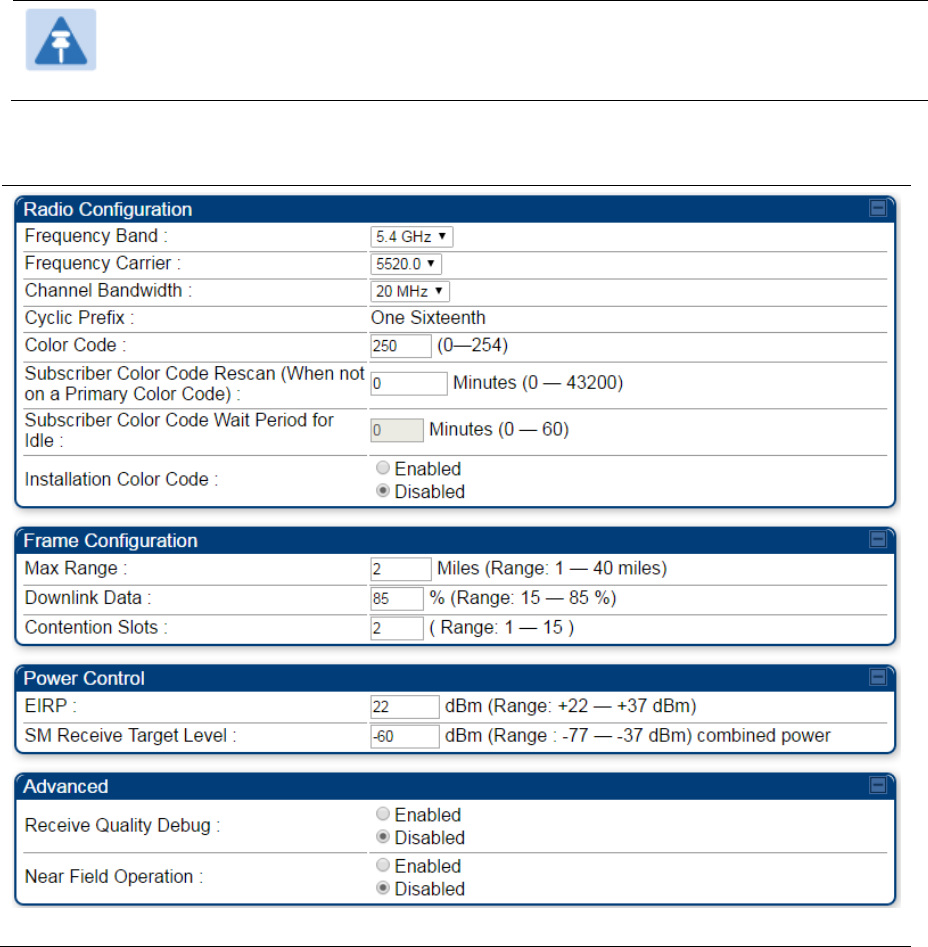
Chapter 7: Configuration Configuring radio parameters
Page 7-128
PMP 450m Series – configuring radio
Radio page - PMP 450m AP 5 GHz
The Radio tab of the PMP 450m AP contains some of the configurable parameters that define how an AP
operates.
Note
Only the frequencies available for your region and the selected Channel bandwidth are
displayed.
Table 141 PMP 450m AP Radio attributes - 5 GHz

Chapter 7: Configuration Configuring radio parameters
Page 7-129
Attribute Meaning
Frequency Band Select the desired operating frequency band.
Frequency Carrier Specify the frequency for the module to transmit. The default for this
parameter is None. For a list of channels in the band, see the drop-down list
on the radio GUI.
Channel Bandwidth The channel size used by the radio for RF transmission. The setting for the
channel bandwidth must match between the AP and the SM. The supported
Channel Bandwidths are 5MHz, 10 MHz, 15 MHz, 20 MHz, and 40 MHz.
Cyclic Prefix OFDM technology uses a cyclic prefix, where a portion of the end of a symbol
(slot) is repeated at the beginning of the symbol to allow multi-pathing to
settle before receiving the desired data. A 1/16 cyclic prefix means that for
every 16 bits of throughput data transmitted, an additional bit is used.
Color Code
Specify a value from 0 to 254. For registration to occur, the color code of the
SM and the AP must match. Color code is not a security feature. Instead,
color code is a management feature, typically for assigning each sector a
different color code.
Color code allows you to force a SM to register to only a specific AP, even
where the SM can communicate with multiple APs. The default setting for the
color code value is 0. This value matches only the color code of 0 (not all 255
color codes).
Subscriber Color
Code Rescan (When
not on a Primary Color
Code)
This timer may be utilized to initiate SM rescans in order to register to an AP
configured with the SM‘s primary color code.
The time (in minutes) for a subscriber to rescan (if this AP is not configured
with the SM‘s primary color code). This timer will only fire once – if the
Subscriber Color Code Wait Period for Idle timer is configured with a
nonzero value and the Subscriber Color Code Rescan expires, the
Subscriber Color Code Wait Period for Idle is started. If the Subscriber
Color Code Wait Period for Idle timer is configured with a zero value and
the Subscriber Color Code Rescan timer expires, the SM will immediately
go into rescan mode
Subscriber Color
Code Wait Period for
Idle
The time (in minutes) for a subscriber to rescan while idle (if this AP is not
configured with the SM’s primary color code). This timer will fire periodic
events. The fired event determines if any RF unicast traffic (either inbound or
outbound) has occurred since the last event. If the results of the event
determine that no RF unicast traffic has occurred (SM is idle), then the
subscriber will rescan.

Chapter 7: Configuration Configuring radio parameters
Page 7-130
Installation Color
Code
With this feature enabled on the AP and SM, operators may install and
remotely configure SMs without having to configure matching color codes
between the modules. While the SM is accessible for configuration from
above the AP (for remote provisioning) and below the SM (for local site
provisioning), no user data is passed over the radio link. When using the
Installation Color Code feature, ensure that the SM is configured with the
factory default Color Code configuration (Color Code 1 is “0”, Color Code 2-
10 set to “0” and “Disable”). The status of the Installation Color Code can be
viewed on the AP Eval web GUI page, and when the SM is registered using
the Installation Color Code the message “SM is registered via ICC – Bridging
Disabled!” is displayed in red on every SM GUI page. The Installation Color
Code parameter is configurable without a radio reboot for both the AP and
SM. If a SM is registered via Installation Color Code and the feature is then
disabled, operators will need to reboot the SM or force it to reregister (i.e.
using Rescan APs functionality on the AP Eval page).
Max Range
Enter a number of miles (or kilometers divided by 1.61, then rounded to an
integer) for the furthest distance from which a SM is allowed to register to this
AP. Do not set the distance to any greater number of miles. A greater
distance
does not increase the power of transmission from the AP.
can reduce aggregate throughput.
For example, with a 20 MHz channel and 2.5 ms frame, every additional 2.24
miles reduces the data air time by one symbol (around 1% of the frame).
Regardless of this distance, the SM must meet the minimum requirements for
an acceptable link. The parameters have to be selected so that there is no
overlap between one AP transmitting and another AP receiving. A co-location
tool is provided to help with selecting sets of parameters that allow co-
location.
The default value of this parameter is 2 miles (3.2 km).
Downlink Data
Specify the percentage of the aggregate throughput for the downlink (frames
transmitted from the AP to the subscriber). For example, if the aggregate
(uplink and downlink total) throughput on the AP is 90 Mb, then 75% specified
for this parameter allocates 67.5 Mb for the downlink and 22.5 Mb for the
uplink. The default for this parameter is 75%. This parameter must be set in
the range of 15% - 85%, otherwise the invalid input will not be accepted and
the previously-entered valid setting is used.
Note
In order to prevent self-interference, the frame configuration
needs to align which includes Downlink Data, Max Range and
Contention slots. For DFS regions, the maximum Downlink % for
a 5.4 GHz radio is 75% only.
Contention Slots
(a.k.a. Control Slots)
This field indicates the number of (reserved) Contention slots configured by
the operator. The SM uses reserved Contention slots and unused data slots
for bandwidth requests. See Contention slots on page 7-176.

Chapter 7: Configuration Configuring radio parameters
Page 7-131
EIRP This field indicates the combined power level at which the AP will transmit,
based on the Country Code. It also includes the antenna gain and array gain.
SM Receive Target
Level
Each SM’s Transmitter Output Power is automatically set by the AP. The AP
monitors the received power from each SM, and adjusts each SM’s
Transmitter Output Power so that the received power at the AP from that SM
is not greater what is set in this field. This value represents the transmitted
and received power (combined power) perceived on the SM.
Receive Quality
Debug To aid in link performance monitoring, the AP and SM now report the number
of fragments received per modulation (i.e. QPSK, 16-QAM, 64-QAM and 256-
QAM) and per channel (polarization).
Note
Due to CPU load, this will slightly degrade packet per second
processing.
Near Field Operation This parameter is enabled by the Near Field Operation control. This is only
available when the EIRP is set to 22 dBm or below.
When Near Field Operation is enabled, the Near Field Range is used to apply
compensation to the unit’s calibration to support operation in the near field.
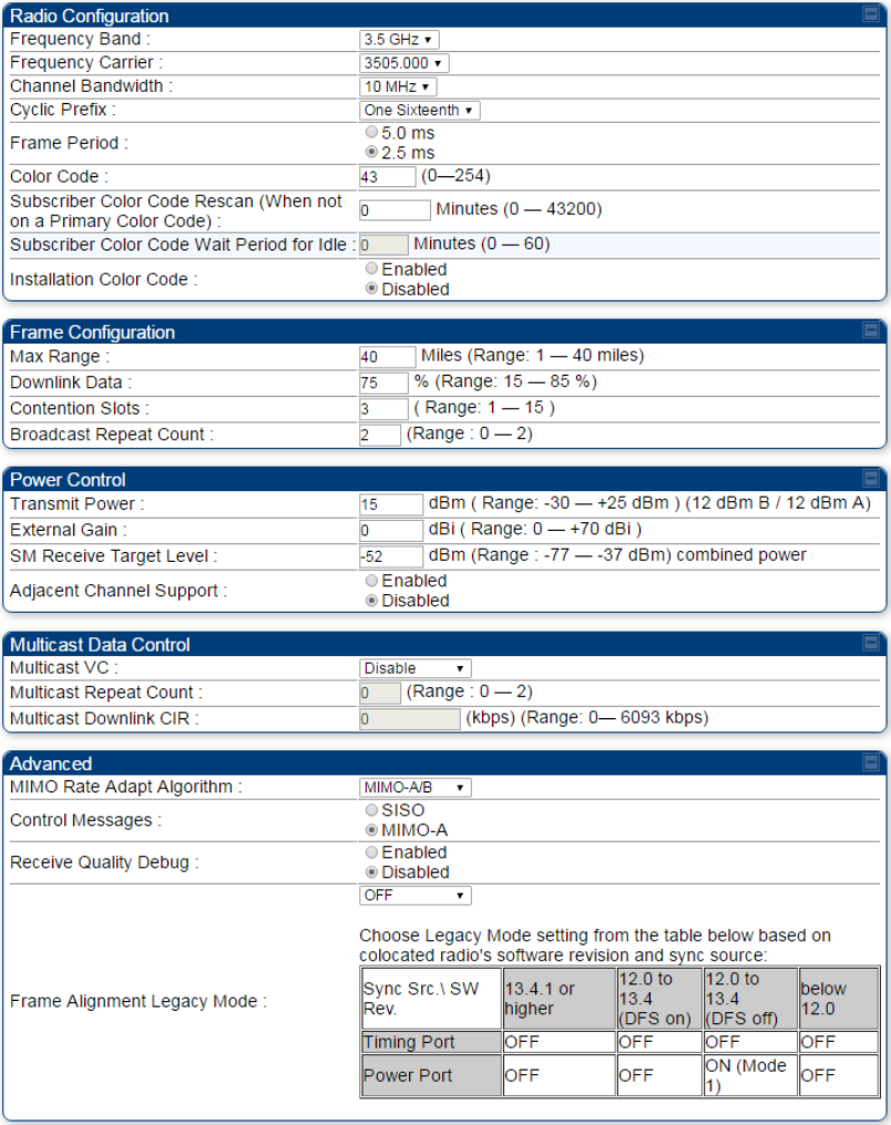
Chapter 7: Configuration Configuring radio parameters
Page 7-132
PMP/PTP 450i Series – configuring radio
Radio page - PMP 450i AP 3 GHz
The Radio tab of the PMP 450i AP 3 GHz is shown in Figure 142.
Figure 142 PMP 450i AP Radio attributes - 3 GHz
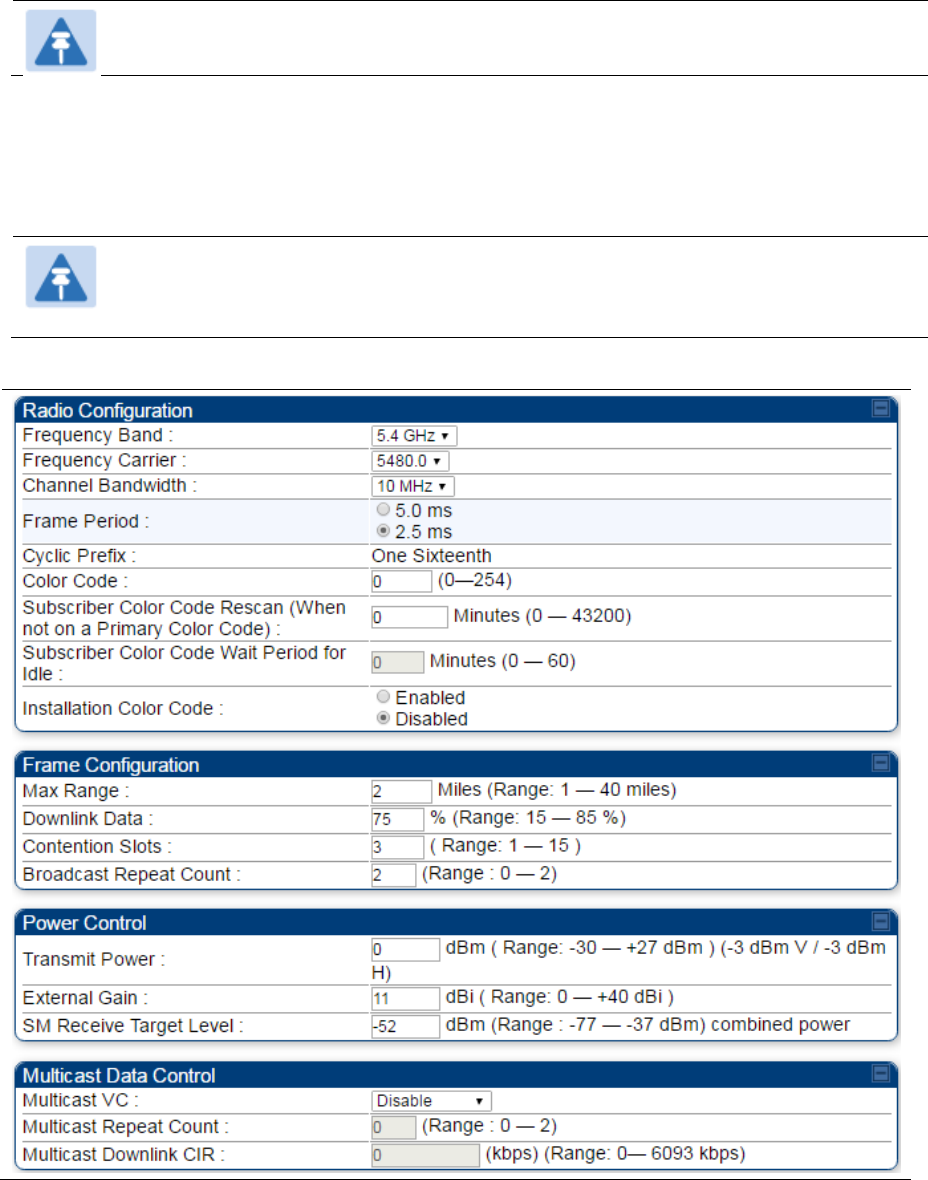
Chapter 7: Configuration Configuring radio parameters
Page 7-133
Note
Refer Table 143 PMP 450i SM Radio attributes – 5 GHz on page 7-138 for parameter details
Radio page - PMP 450i AP 5 GHz
The Radio tab of the PMP 450i AP contains some of the configurable parameters that define how an AP
operates.
Note
Only the frequencies available for your region and the selected Channel bandwidth are
displayed.
Table 142 PMP 450i AP Radio attributes - 5 GHz
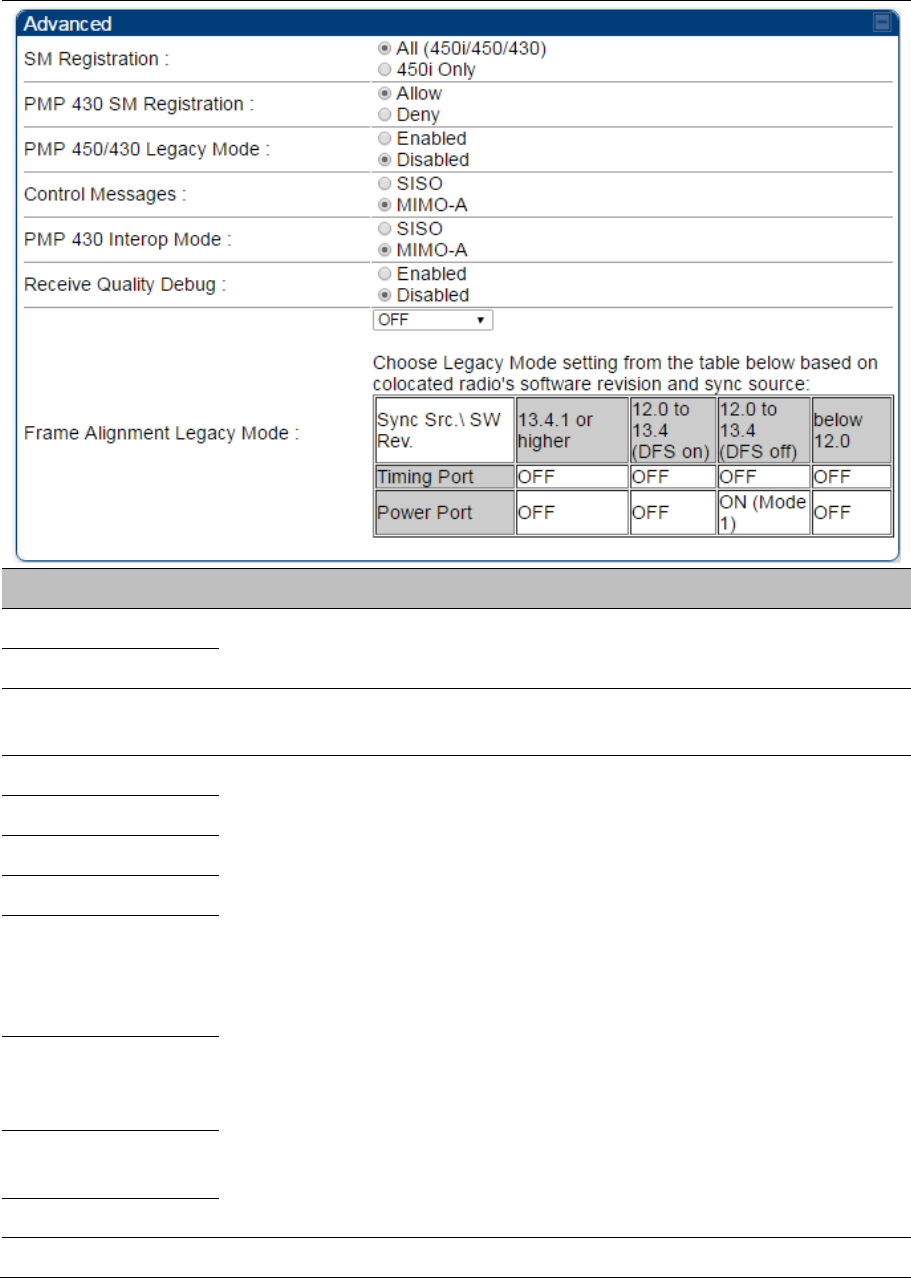
Chapter 7: Configuration Configuring radio parameters
Page 7-134
Attribute Meaning
Frequency Band See Table 141 PMP 450m AP Radio attributes - 5 GHz on page 7-127
Frequency Carrier
Alternate Frequency
Carrier 1 and 2
These parameters are displayed based on Regional Settings. Refer Country
on page 7-70
Channel Bandwidth
See Table 141 PMP 450m AP Radio attributes - 5 GHz on page 7-127
Cyclic Prefix
Frame Period
Color Code
Subscriber Color
Code Rescan (When
not on a Primary Color
Code)
Subscriber Color
Code Wait Period for
Idle
Installation Color
Code
Max Range
Downlink Data See Table 141 PMP 450m AP Radio attributes - 5 GHz on page 7-127

Chapter 7: Configuration Configuring radio parameters
Page 7-135
Contention Slots
(a.k.a. Control Slots)
This field indicates the number of (reserved) Contention slots configured by
the operator. The SM uses reserved Contention slots and unused data slots
for bandwidth requests. See Contention slots on page7-176.
Broadcast Repeat
Count
The default is 2 repeats (in addition to the original broadcast packet, for a
total of 3 packets sent for every one needed), and is settable to 1 or 0 repeats
(2 or 1 packets for every broadcast).
ARQ (Automatic Repeat reQuest) is not present in downlink broadcast
packets, since it can cause unnecessary uplink traffic from every SM for each
broadcast packet. For successful transport without ARQ, the AP repeats
downlink broadcast packets. The SMs filter out all repeated broadcast
packets and, thus, do not transport further.
The default of 2 repeats is optimum for typical uses of the network as an
internet access system. In applications with heavy download broadcast such
as video distribution, overall throughput is significantly improved by setting the
repeat count to 1 or 0. This avoids flooding the downlink with repeat
broadcast packets.
Transmitter Output
Power
This value represents the combined power of the AP’s two transmitters.
Nations and regions may regulate transmitter output power. For example
900 MHz, 5.4 GHz and 5.8 GHz modules are available as connectorized
radios, which require the operator to adjust power to ensure regulatory
compliance.
The professional installer of the equipment has the responsibility to
maintain awareness of applicable regulations.
calculate the permissible transmitter output power for the module.
confirm that the initial power setting is compliant with national or regional
regulations.
confirm that the power setting is compliant following any reset of the
module to factory defaults.
External Gain This value needs to correspond to the published gain of the antenna used to
ensure the radio will meet regulatory requirements.
SM Receive Target
Level See Table 141 PMP 450m AP Radio attributes - 5 GHz on page 7-127
Multicast VC Data
Rate
This pull down menu of the Multicast Data Control screen helps in configuring
multicast packets to be transmitted over a dedicated channel at a
configurable rate of 1X, 2X, 4X or 6X. The default value is “Disable”. If set to
the default value, all multicast packets are transmitted over the Broadcast VC
data path. This feature is available only for the PMP 450 Series and is not
backward compatible with PMP 430 series of radios.
Chapter 7: Configuration Configuring radio parameters
Page 7-136
Multicast Repeat
Count
This value is the number of packets that are repeated for every multicast VC
packet received on the AP (located under Radio tab of Configuration).
Multicast (like Broadcast) packets go over a VC that is shared by all SMs, so
there is no guaranteed delivery. The repeat count is an attempt to improve the
odds of the packets getting over the link. If the user has issues with packets
getting dropped, they can use this parameter to improve the performance at
the cost of the overall throughput possible on that channel. The default value
is 0.
Multicast Downlink
CIR
This value is the committed information rate for the multicast downlink VC
(located under the Radio tab of Configuration). The default value is 0 kbps.
The range of this parameter is based on the number of repeat counts. The
higher the repeat count, the lower the range for the multicast downlink CIR.
SM Registration All This field allows to control registration of all type 450 Platform Family SM
including 430 Series SM(450i/450/430) or 450i Series SM only.
PMP 430 SM
Registration
This field allows to control of PMP 430 SMs whether PMP 430 SMs are
allowed to register to PMP 450i APs. By default, it is enabled and PMP 430
SM registrations are accepted.
When this field is set to disabled, PMP 430 SM’s registrations fail with reject
reason 8. This will cause SMs to lock out the AP for 15 minutes.
Note
This option is not displayed if the Frame Period is set to 5
ms. This option applies only to PMP 450/450i Series APs -
5 GHz.
Control Message Controls whether the control messages are sent in MIMO-B or MIMO-A
mode. MIMO-A is recommended. However, if an AP on 13.2 is attempting to
connect to an SM on 13.1.3 or before, changing to MIMO-B may aid in
getting the SM registered.
PMP 450/430 Legacy
mode
Disabled: It is factory default setting. It allows to operate in 450i Series
capabilities.
Enabled: It allows to operate radio in Legacy mode PMP 450 or 430.
PMP 430 Interop
Mode
For n-1 compatibility, In SISO mode this forces the AP to only send Control
and Beacons over one of the RF paths.
Receive Quality
Debug
To aid in link performance monitoring, the AP and SM now report the number
of fragments received per modulation (i.e. QPSK, 16-QAM, 64-QAM) and per
channel (polarization).
Note
Due to CPU load, this will slightly degrade packet per second
processing.
Frame Alignment Legacy
Mode
Mode Behavior (non-900 MHz
radios)
Behavior (FSK 900 MHz
radios)

Chapter 7: Configuration Configuring radio parameters
Page 7-137
OFF
By default frame start is
aligned with devices with
Timing Port
synchronization
If the synchronization
source changes (due to
Autosync or otherwise)
the radio will dynamically
adjust its frame start to
maintain alignment with
the default frame start
timing
By default frame start is
aligned with FSK 900
MHz devices with Timing
Port synchronization
If the synchronization
source changes (due to
Autosync or otherwise)
the radio will dynamically
adjust its frame start to
maintain alignment with
the default frame start
timing
ON
(Mode 1)
The radio will align with
devices running software
versions from 12.0 to
13.4.
The radio will align with
FSK 900 MHz devices
running software versions
from 12.0 to 13.4.
ON
(Mode 2)
N/A
The radio will align with
FSK 900 MHz devices
with software versions
11.2 or older.
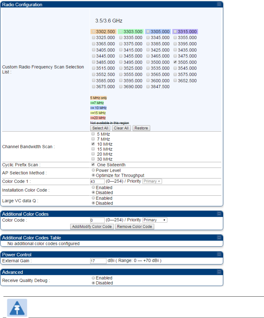
Chapter 7: Configuration Configuring radio parameters
Page 7-138
Radio page - PMP 450i SM 3 GHz
The Radio tab of the PMP 450i SM 3 GHz is shown in Figure 143.
Figure 143 PMP 450i SM Radio attributes - 3 GHz
Note
Refer Table 143 PMP 450i SM Radio attributes – 5 GHz on page 7-138 for parameter details
Chapter 7: Configuration Configuring radio parameters
Page 7-139
Radio page – PMP 450i SM 5 GHz
The Radio page of PMP 450i SM is explained in Table 143.
Table 143 PMP 450i SM Radio attributes – 5 GHz
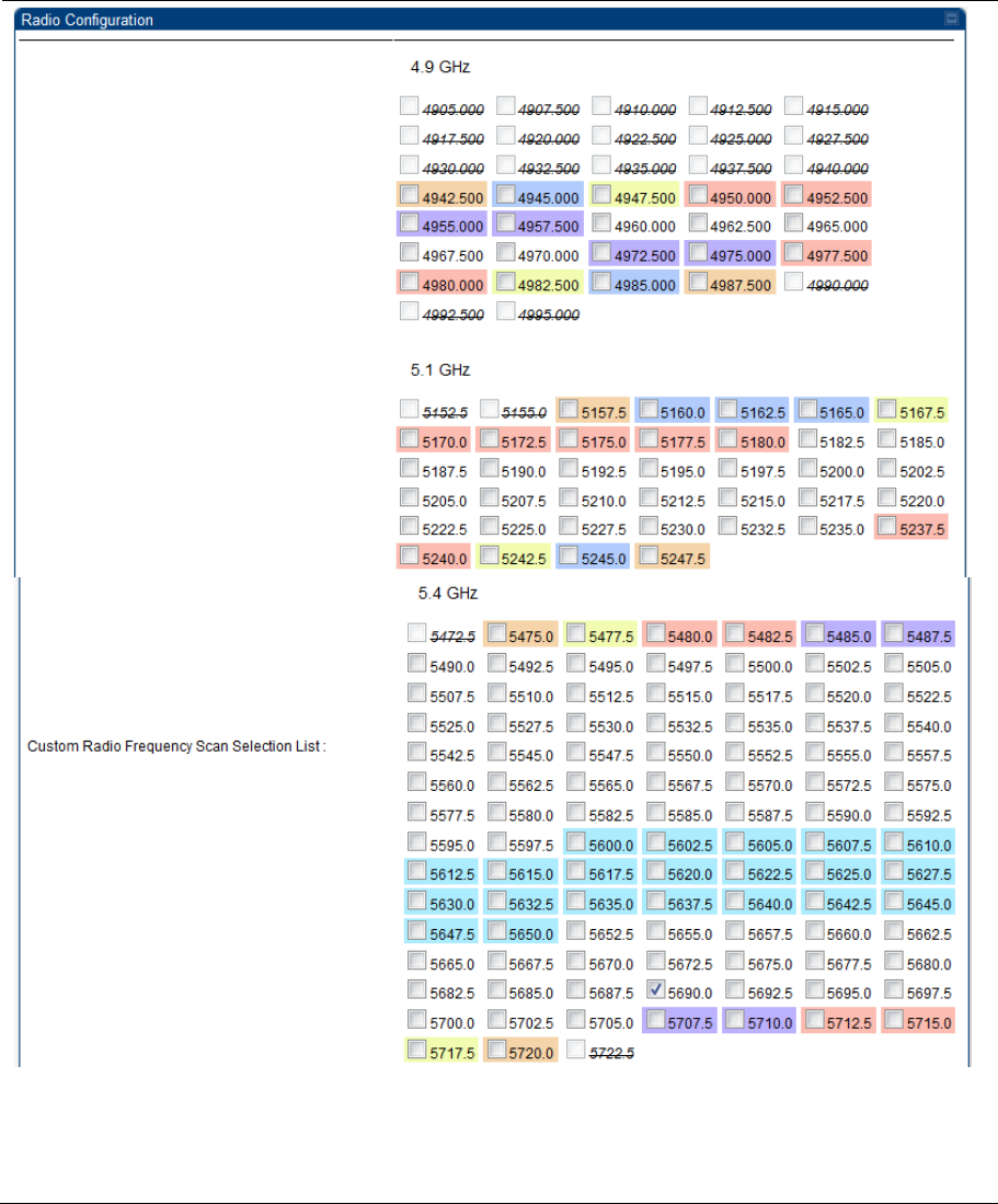
Chapter 7: Configuration Configuring radio parameters
Page 7-140
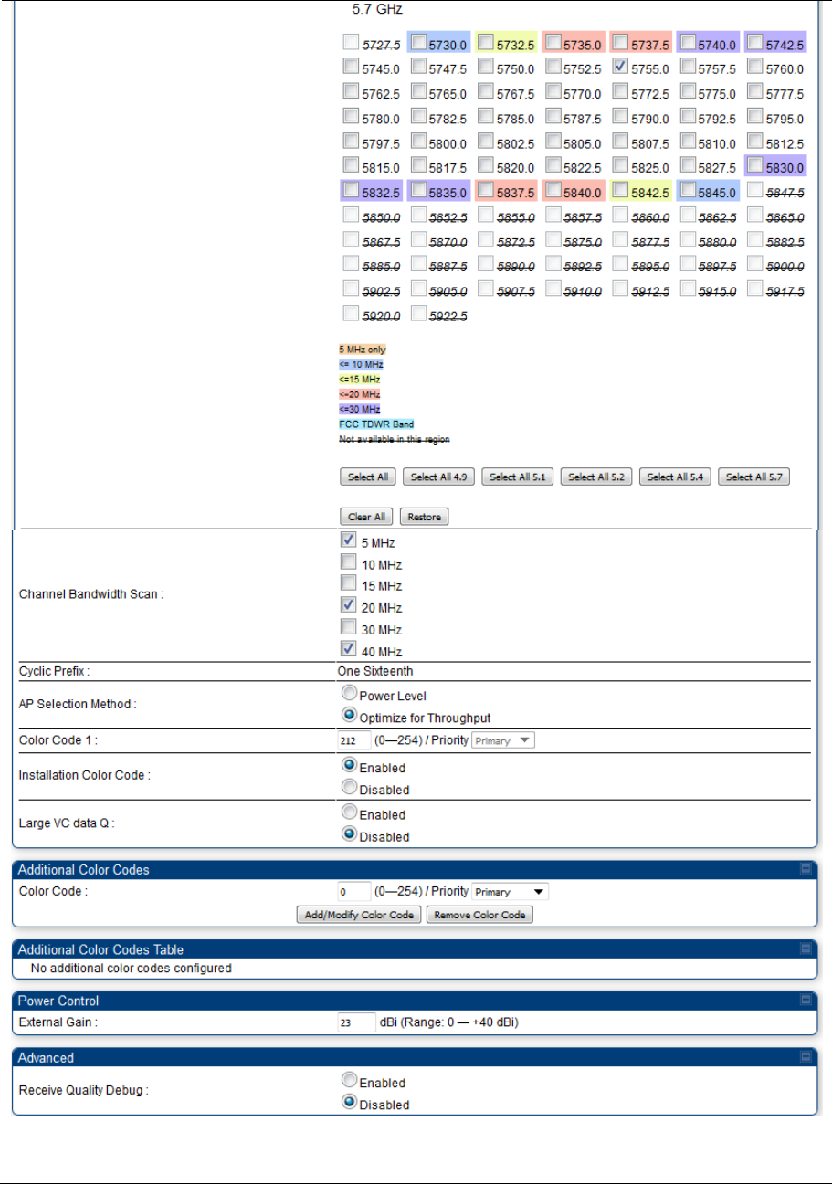
Chapter 7: Configuration Configuring radio parameters
Page 7-141
Chapter 7: Configuration Configuring radio parameters
Page 7-142
Attribute Meaning
Custom Radio
Frequency Scan
Selection List
Check the frequencies that SM has to scan for AP transmissions. See Radio
Frequency Scan Selection List on page 7-169.
Channel Bandwidth
Scan
The channel size used by the radio for RF transmission.
Note
Selecting multiple channel bandwidths will increase registration
and re-registration times.
Cyclic Prefix Scan The cyclic prefix for which AP scanning is executed.
AP Selection Method Operators may configure the method by which a scanning SM selects an AP.
By default, AP Selection Method is set to “Optimize for Throughput”, which
has been the mode of operation in releases prior to 12.0.3.1.
Power Level: AP selection based solely on power level
Note
For operation with a PMP 450m AP, select the Power Level
option
or
Optimize for Throughput: AP selection based on throughput optimization –
the selection decision is based on power level (which affects the modulation
state), channel bandwidth (which affects throughput) and number of SM
registrations to the AP (which affects system contention performance).
Color Code 1 Color code allows you to force the SM to register to only a specific AP, even
where the SM can communicate with multiple APs. For registration to occur,
the color code of the SM and the AP must match. Specify a value from 0 to
254.
Color code is not a security feature. Instead, color code is a management
feature, typically for assigning each sector a different color code. The default
setting for the color code value is 0. This value matches only the color code
of 0 (not all 255 color codes).
SMs may be configured with up to 20 color codes. These color codes can be
tagged as Primary, Secondary, or Tertiary, or Disable. When the SM is
scanning for APs, it will first attempt to register to an AP that matches one of
the SM’s primary color codes. Failing that, the SM will continue scanning and
attempt to register to an AP that matches one of the SM’s secondary color
codes. Failing that, the SM will continue scanning and attempt to register to
an AP that matches one of the SM’s tertiary color codes. This is all done in
the scanning mode of the SM and will repeat until a registration has occurred.

Chapter 7: Configuration Configuring radio parameters
Page 7-143
Color codes in the same priority group are treated equally. For example, all
APs matching one of the SM’s primary color codes are analyzed equally.
Likewise, this evaluation is done for the secondary and tertiary groups in
order. The analysis for selecting an AP within a priority group is based on
various inputs, including signal strength and number of SMs already
registered to each AP.
The first color code in the configuration is the pre-Release 9.5 color code.
Thus, it is always a primary color code for legacy reasons.
The color codes can be disabled, with the exception of the first color code.
Installation Color
Code
With this feature enabled on the AP and SM, operators may install and
remotely configure SMs without having to configure matching color codes
between the modules. When using the Installation Color Code feature, ensure
that the SM is configured with the factory default Color Code configuration
(Color Code 1 is “0”, Color Code 2-10 set to “0” and “Disable”). The status of
the Installation Color Code can be viewed on the AP Eval web GUI page, and
when the SM is registered using the Installation Color Code the message “SM
is registered via ICC – Bridging Disabled!” is displayed in red on every SM
GUI page. The Installation Color Code parameter is configurable without a
radio reboot for both the AP and SM.
External Gain This value represents the antenna gain.
For ODUs with integrated antenna, this is set at the correct value in the
factory.
For Connectorized ODUs with external antenna, the user must set this value
to the overall antenna gain, including any RF cable loss between the ODU
and the antenna.
Large VC data Queue SM and BH have a configurable option used to prevent packet loss in the
uplink due to bursting IP traffic. This is designed for IP burst traffic particular
to video surveillance applications.
Receive Quality
Debug
To aid in link performance monitoring, the AP and SM now report the number
of fragments received per modulation (i.e. QPSK, 16-QAM, 64-QAM) and per
channel (polarization).
Note
Due to CPU load, this will slightly degrade packet per second
processing.
Note
The frequencies that a user can select are controlled by the country or a region and the
Channel Bandwidth selected. There can be a case where a user adds a custom frequency
(from the Custom Frequencies page on page 7-172) and cannot see it in the pull down
menu.
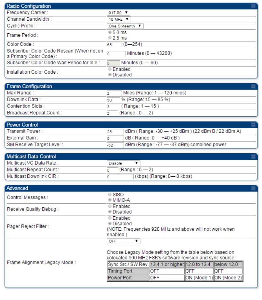
Chapter 7: Configuration Configuring radio parameters
Page 7-144
Radio page - PMP 450i AP 900 MHz
The Radio tab of the PMP 450i AP 900 MHz is described in below table Table 144.
Table 144 PMP 450i AP Radio attributes - 900 MHz

Chapter 7: Configuration Configuring radio parameters
Page 7-145
Attribute Meaning
Frequency Carrier Specify the frequency for the module to transmit. The default for this
parameter is None. For a list of channels in the band, see the drop-down
list on the radio GUI.
Channel Bandwidth The channel size used by the radio for RF transmission. The setting for
the channel bandwidth must match between the AP and the SM. The
supported Channel Bandwidths are 5, 7, 10 and 20 MHz.
Cyclic Prefix
See Table 141 PMP 450m AP Radio attributes - 5 GHz on page 7-127.
Frame Period
Color Code
Subscriber Color Code
Rescan (When not on a
Primary Color Code)
Subscriber Color Code
Wait Period for Idle
Installation Color Code
Max Range
See Table 141 PMP 450m AP Radio attributes - 5 GHz on page 7-127.
Downlink Data
Contention Slots
(a.k.a. Control Slots)
Broadcast Repeat Count
Transmitter Output Power See Table 142 PMP 450i AP Radio attributes - 5 GHz on page 7-132.
External Gain
SM Receive Target Level
See Table 141 PMP 450m AP Radio attributes - 5 GHz on page 7-127
Multicast VC Data Rate
Multicast Repeat Count
Multicast Downlink CIR
Control Message
Receive Quality Debug
Pager Reject Filter In 900 MHz, Pager Reject filter is placed on the AP to block Pager signals
which could cause interference to the whole band. The Pager signals
typically operate in the 928-930 frequency range. When the filter is
enabled, the signals of 920 MHz and above are attenuated which enables
better reception of signals in the rest of the band. Note that the AP/SM
should not be configured on the frequencies of 920 MHz and above when
this filter is enabled.
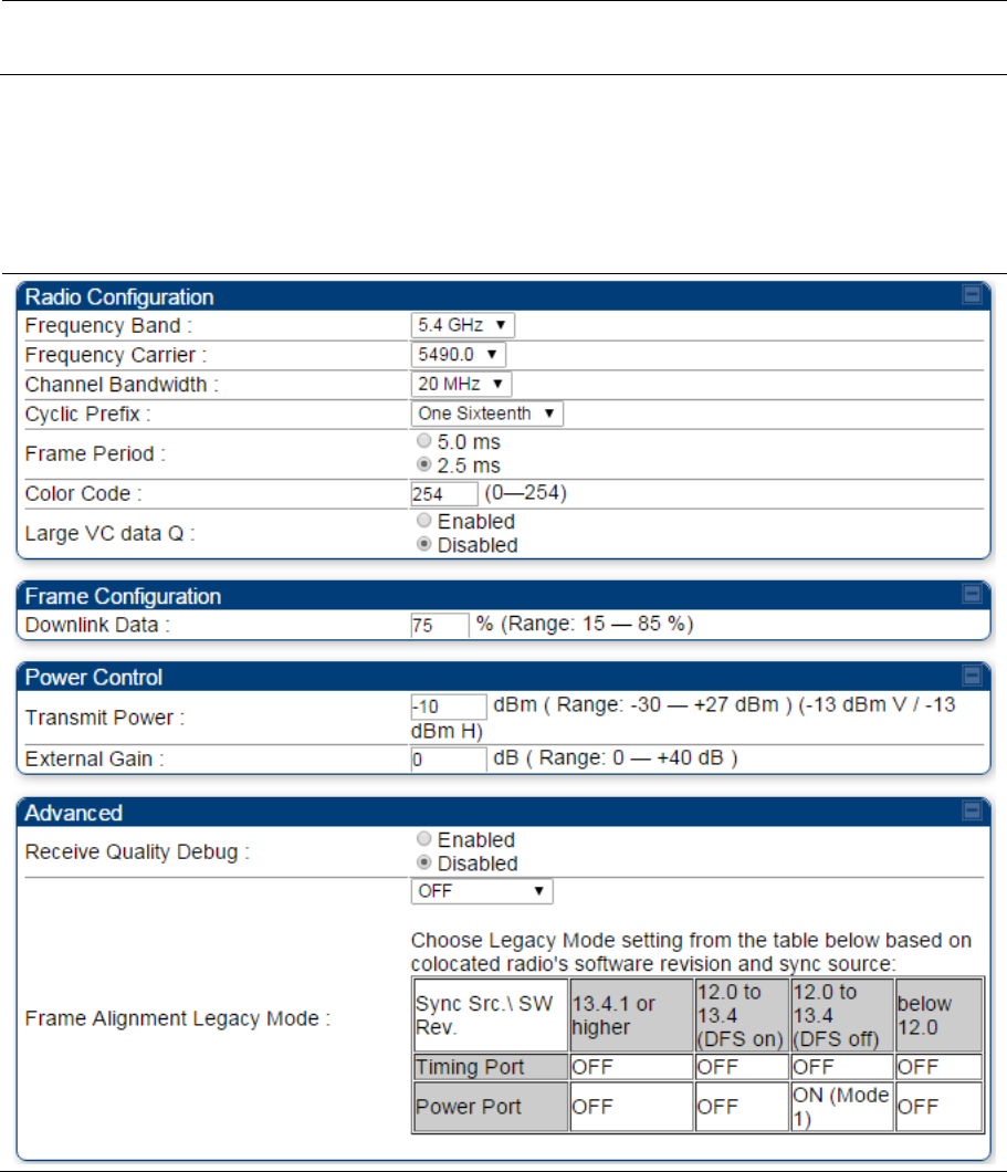
Chapter 7: Configuration Configuring radio parameters
Page 7-146
Frame Alignment Legacy
Mode See Table 142 PMP 450i AP Radio attributes - 5 GHz on page 7-132.
Radio page - PTP 450i BHM 5 GHz
The Radio page of PTP 450i BHM is explained in Table 145.
Table 145 PTP 450i BHM Radio page attributes – 5 GHz

Chapter 7: Configuration Configuring radio parameters
Page 7-147
Attribute Meaning
Frequency Band Select the operating frequency band of the radio. The supported bands are
4.9 GHz, 5.4 GHz and 5.7 GHz.
Frequency Carrier Specify the frequency for the module to transmit. The default for this
parameter is None. For a list of channels in the band, see the drop-down list
on the radio GUI.
Channel Bandwidth The channel size used by the radio for RF transmission. The setting for the
channel bandwidth must match between the BHM and the BHS.
Cyclic Prefix OFDM technology uses a cyclic prefix, where a portion of the end of a symbol
(slot) is repeated at the beginning of the symbol to allow multi-pathing to
settle before receiving the desired data. A 1/16 cyclic prefix means that for
every 16 bits of throughput data transmitted, an additional bit is used.
Frame Period Select the Frame Period of the radio. The support Frame Periods are : 5 ms
and 2.5 ms.
Color Code Specify a value from 0 to 254. For registration to occur, the color code of the
BHM and the BHS must match. Color code is not a security feature. Instead,
color code is a management feature, typically for assigning each link a
different color code.
Color code allows you to force a BHS to register to only a specific BHM. The
default setting for the color code value is 0. This value matches only the
color code of 0 (not all 255 color codes).
Large VC data Q Enable Large VC Q for applications that burst data high rates. Large Qs may
decrease effective throughput for TCP application.
Disable Large VC Q if application need not handle bursts of data. Large Qs
may decrease effective throughput for TCP application.
Downlink Data
Specify the percentage of the aggregate throughput for the downlink (frames
transmitted from the BHM to the subscriber). For example, if the aggregate
(uplink and downlink total) throughput on the BHM is 132 Mbps, then 75%
specified for this parameter allocates 99 Mbps for the downlink and 33 Mbps
for the uplink. The default for this parameter is 50%. This parameter must be
set in the range of 15% - 85%, otherwise the invalid input will not be accepted
and the previously-entered valid setting is used.
Note
In order to prevent self-interference, the frame configuration
needs to align. This includes Downlink Data, Max Range and
Contention slots.
Transmit Power
This value represents the combined power of the BHM’s two transmitters.
Nations and regions may regulate transmit power. For example
PTP 450i Series modules are available as connectorized radios, which
require the operator to adjust power to ensure regulatory compliance.

Chapter 7: Configuration Configuring radio parameters
Page 7-148
The professional installer of the equipment has the responsibility to:
Maintain awareness of applicable regulations.
Calculate the permissible transmitter output power for the module.
Confirm that the initial power setting is compliant with national or regional
regulations.
Confirm that the power setting is compliant following any reset of the module
to factory defaults.
External Gain This value needs to correspond to the published gain of the antenna used to
ensure the radio will meet regulatory requirements.
Receive Quality
Debug
To aid in link performance monitoring, the BHM and BHS now report the
number of fragments received per modulation (i.e. QPSK, 16-QAM, 64-QAM
and 256-QAM) and per channel (polarization).
Note
Due to CPU load, this slightly degrades the packet during per
second processing.
Frame Alignment
Legacy Mode See Table 142 PMP 450i AP Radio attributes - 5 GHz on page 7-132.
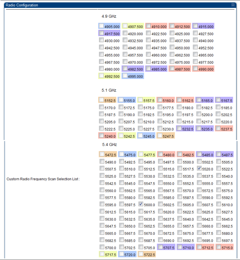
Chapter 7: Configuration Configuring radio parameters
Page 7-149
Radio page – PTP 450i BHS 5 GHz
The Radio page of PTP 450i BHS is explained in Table 146.
Table 146 PTP 450i BHS Radio attributes – 5 GHz
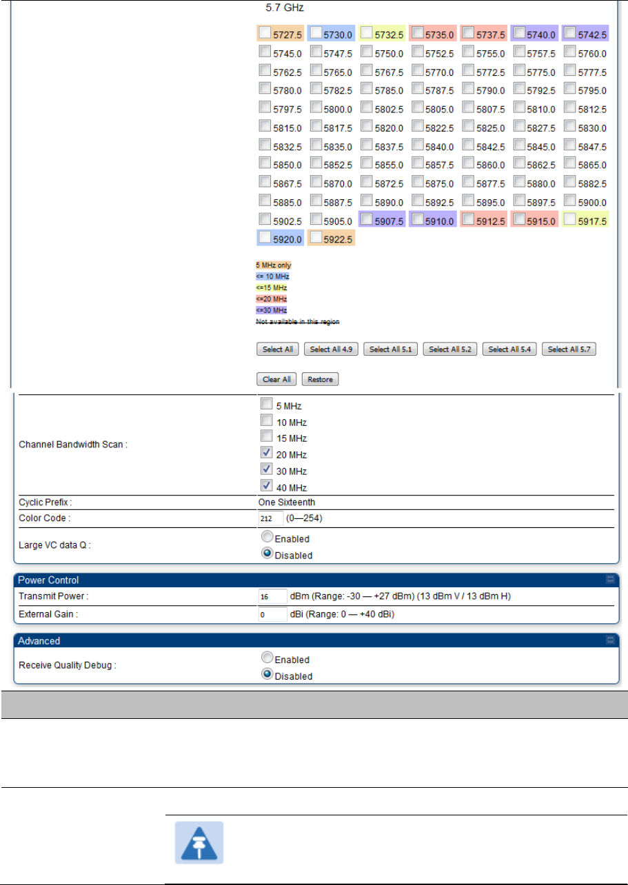
Chapter 7: Configuration Configuring radio parameters
Page 7-150
Attribute Meaning
Custom Radio
Frequency Scan
Selection List
Check any frequency that you want the BHS to scan for BHM transmissions.
See Radio Frequency Scan Selection List on page 7-169.
Channel Bandwidth
Scan
The channel size used by the radio for RF transmission.
Note
Selecting multiple channel bandwidths will increase registration
and re-registration times.

Chapter 7: Configuration Configuring radio parameters
Page 7-151
Cyclic Prefix Scan The cyclic prefix for which BHM scanning is executed.
Color Code Color code allows to force the BHS to register to only a specific BHM, even
where the BHS can communicate with multiple BHMs. For registration to
occur, the color code of the BHS and the BHM must match. Specify a value
from 0 to 254.
The color codes can be disabled, with the exception of the first color code.
Large VC data Q BHM and BHS have a configurable option used to prevent packet loss in the
uplink due to bursting IP traffic. This is designed for IP burst traffic particular
to video surveillance applications.
Transmit Power Refer Table 145 PTP 450i BHM Radio page attributes – 5 GHz on page 7-145
External Gain
Receive Quality
Debug
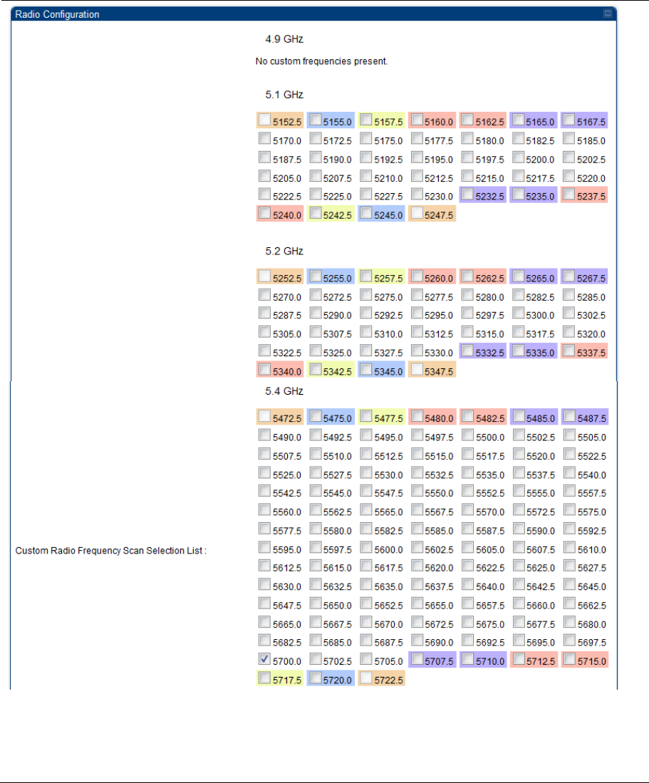
Chapter 7: Configuration Configuring radio parameters
Page 7-152
PMP 450b Series - configuring radio
Radio page – PMP 450b SM 5 GHz
The Radio page of PMP 450b SM is explained in Table 147.
Table 147 PMP 450b SM Radio attributes – 5 GHz
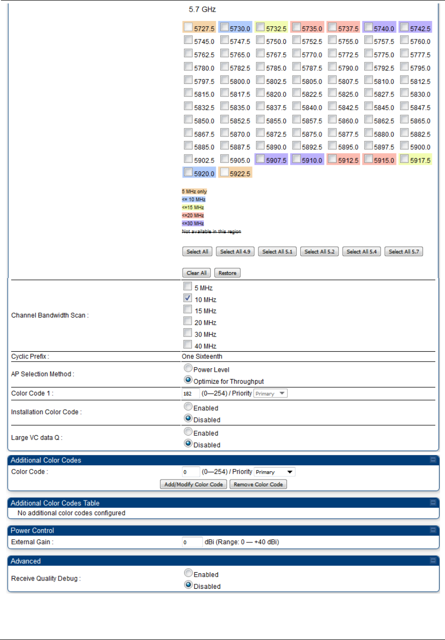
Chapter 7: Configuration Configuring radio parameters
Page 7-153

Chapter 7: Configuration Configuring radio parameters
Page 7-154
Attribute Meaning
Custom Radio
Frequency Scan
Selection List
Check the frequencies that SM has to scan for AP transmissions. See Radio
Frequency Scan Selection List on page 7-169.
Channel Bandwidth
Scan
The channel size used by the radio for RF transmission.
Note
Selecting multiple channel bandwidths will increase registration
and re-registration times.
Cyclic Prefix Scan The cyclic prefix for which AP scanning is executed.
AP Selection Method Operators may configure the method by which a scanning SM selects an AP.
By default, AP Selection Method is set to “Optimize for Throughput”, which
has been the mode of operation in releases prior to 12.0.3.1.
Power Level: AP selection based solely on power level
Note
For operation with a PMP 450m AP, select the Power Level
option
or
Optimize for Throughput: AP selection based on throughput optimization –
the selection decision is based on power level (which affects the modulation
state), channel bandwidth (which affects throughput) and number of SM
registrations to the AP (which affects system contention performance).
Color Code 1 Color code allows you to force the SM to register to only a specific AP, even
where the SM can communicate with multiple APs. For registration to occur,
the color code of the SM and the AP must match. Specify a value from 0 to
254.
Color code is not a security feature. Instead, color code is a management
feature, typically for assigning each sector a different color code. The default
setting for the color code value is 0. This value matches only the color code
of 0 (not all 255 color codes).
SMs may be configured with up to 20 color codes. These color codes can be
tagged as Primary, Secondary, or Tertiary, or Disable. When the SM is
scanning for APs, it will first attempt to register to an AP that matches one of
the SM’s primary color codes. Failing that, the SM will continue scanning and
attempt to register to an AP that matches one of the SM’s secondary color
codes. Failing that, the SM will continue scanning and attempt to register to
an AP that matches one of the SM’s tertiary color codes. This is all done in
the scanning mode of the SM and will repeat until a registration has occurred.

Chapter 7: Configuration Configuring radio parameters
Page 7-155
Color codes in the same priority group are treated equally. For example, all
APs matching one of the SM’s primary color codes are analyzed equally.
Likewise, this evaluation is done for the secondary and tertiary groups in
order. The analysis for selecting an AP within a priority group is based on
various inputs, including signal strength and number of SMs already
registered to each AP.
The first color code in the configuration is the pre-Release 9.5 color code.
Thus, it is always a primary color code for legacy reasons.
The color codes can be disabled, with the exception of the first color code.
Installation Color
Code
With this feature enabled on the AP and SM, operators may install and
remotely configure SMs without having to configure matching color codes
between the modules. When using the Installation Color Code feature, ensure
that the SM is configured with the factory default Color Code configuration
(Color Code 1 is “0”, Color Code 2-10 set to “0” and “Disable”). The status of
the Installation Color Code can be viewed on the AP Eval web GUI page, and
when the SM is registered using the Installation Color Code the message “SM
is registered via ICC – Bridging Disabled!” is displayed in red on every SM
GUI page. The Installation Color Code parameter is configurable without a
radio reboot for both the AP and SM.
External Gain This value represents the antenna gain.
For ODUs with integrated antenna, this is set at the correct value in the
factory.
For Connectorized ODUs with external antenna, the user must set this value
to the overall antenna gain, including any RF cable loss between the ODU
and the antenna.
Large VC data Queue SM and BH have a configurable option used to prevent packet loss in the
uplink due to bursting IP traffic. This is designed for IP burst traffic particular
to video surveillance applications.
Receive Quality
Debug
To aid in link performance monitoring, the AP and SM now report the number
of fragments received per modulation (i.e. QPSK, 16-QAM, 64-QAM) and per
channel (polarization).
Note
Due to CPU load, this will slightly degrade packet per second
processing.
Note
The frequencies that a user can select are controlled by the country or a region and the
Channel Bandwidth selected. There can be a case where a user adds a custom frequency
(from the Custom Frequencies page on page 7-172) and cannot see it in the pull down
menu.
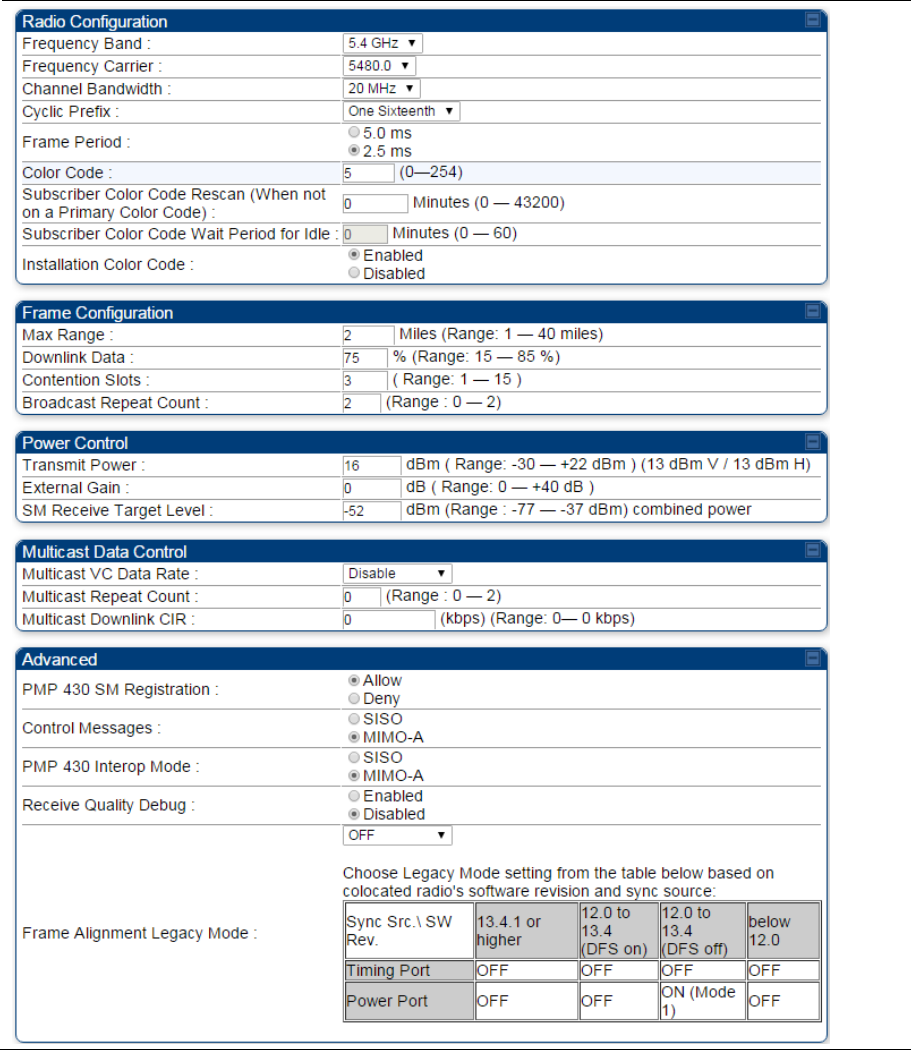
Chapter 7: Configuration Configuring radio parameters
Page 7-156
PMP/PTP 450 Series – configuring radio
Radio page - PMP 450 AP 5 GHz
The Radio tab of the AP for 5 GHz is as shown in Table 148.
Table 148 PMP 450 AP Radio attributes - 5 GHz
Chapter 7: Configuration Configuring radio parameters
Page 7-157
Attribute Meaning
Radio Configuration, Frame
Configuration, Power
Control, Multicast Data
Control and Advance tab
See Table 142 PMP 450i AP Radio attributes - 5 GHz on page 7-132.
PMP 430 SM Registration
See Table 142 PMP 450i AP Radio attributes - 5 GHz on page 7-132.
PMP 450/430 Legacy Mode
Control Messages
PMP 430 Interop Mode
Receive Quality Debug
Frame Alignment Legacy
Mode
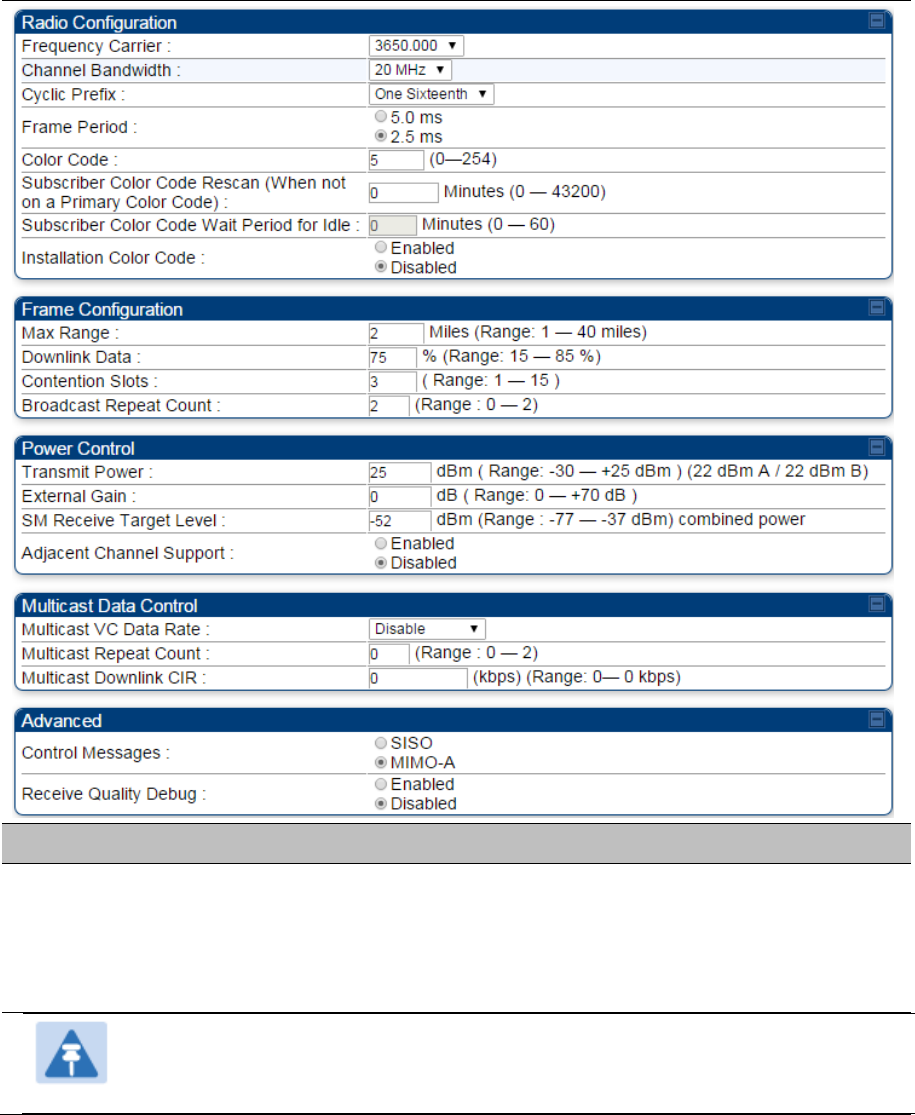
Chapter 7: Configuration Configuring radio parameters
Page 7-158
Radio page - PMP 450 AP 3.65 GHz
Table 149 PMP 450 AP Radio attributes - 3.65 GHz
Attribute Meaning
Radio Configuration,
Frame Configuration,
Power Control, Multicast
Data Control and
Advance tab
See Table 142 PMP 450i AP Radio attributes - 5 GHz on page 7-132.
Note
When the Channel bandwidth is updated from 20 MHz to 30 MHz not more than 59
subscriber can be registered.
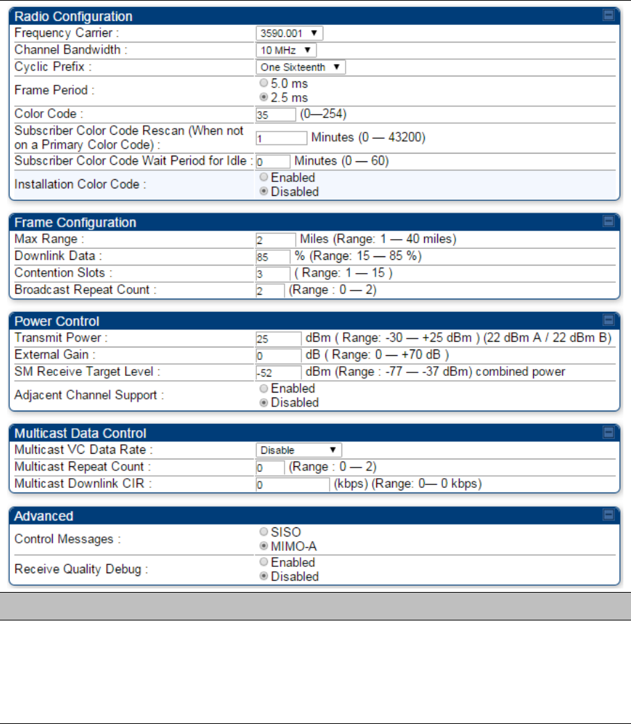
Chapter 7: Configuration Configuring radio parameters
Page 7-159
Radio page - PMP 450 AP 3.5 GHz
Table 150 PMP 450 AP Radio attributes - 3.5 GHz
Attribute Meaning
Radio Configuration,
Frame Configuration,
Power Control, Multicast
Data Control and
Advance tab
See Table 142 PMP 450i AP Radio attributes - 5 GHz on page 7-132.
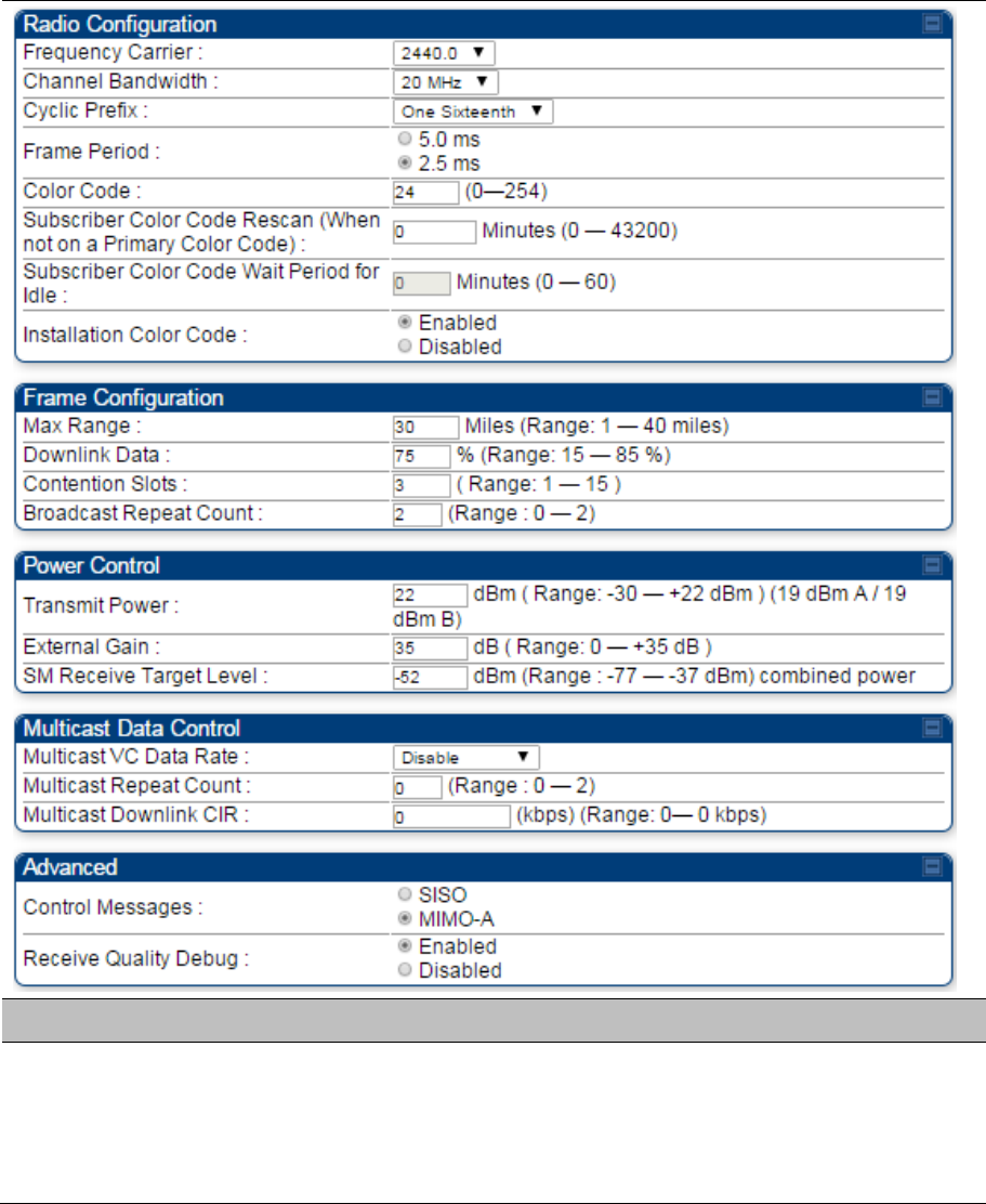
Chapter 7: Configuration Configuring radio parameters
Page 7-160
Radio page - PMP 450 AP 2.4 GHz
Table 151 PMP 450 AP Radio attributes - 2.4 GHz
Attribute Meaning
Radio Configuration,
Frame Configuration,
Power Control, Multicast
Data Control and
Advance tab
See Table 142 PMP 450i AP Radio attributes - 5 GHz on page 7-132.
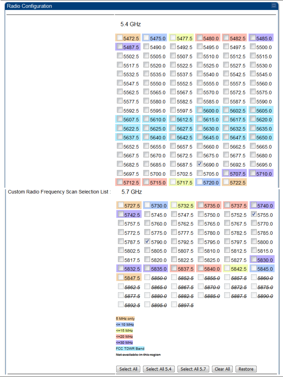
Chapter 7: Configuration Configuring radio parameters
Page 7-161
Radio page - PMP 450 SM 5 GHz
Table 152 PMP 450 SM Radio attributes – 5 GHz
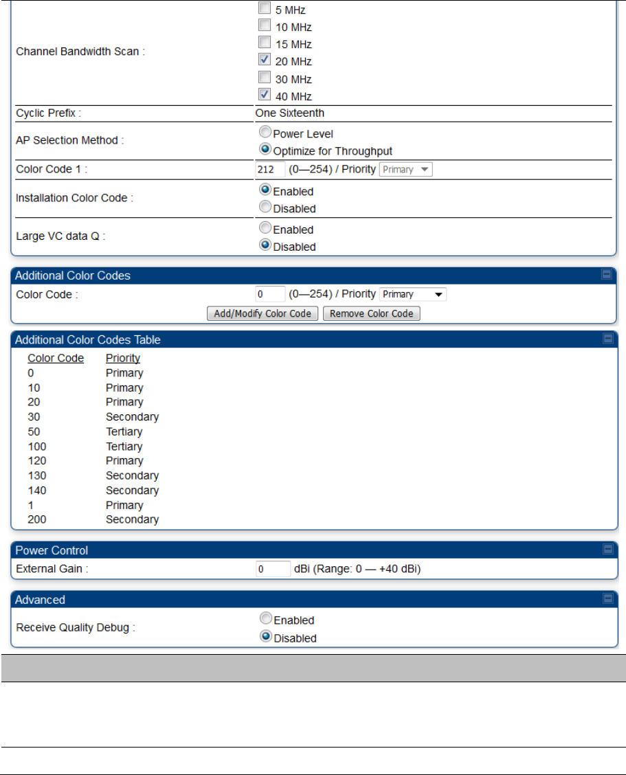
Chapter 7: Configuration Configuring radio parameters
Page 7-162
Attribute Meaning
Custom Radio
Frequency Scan
Selection List
Check the frequencies that SM has to scan for AP transmissions. See Radio
Frequency Scan Selection List on page 7-169.
See Table 142 PMP 450i AP Radio attributes - 5 GHz on page 7-132.
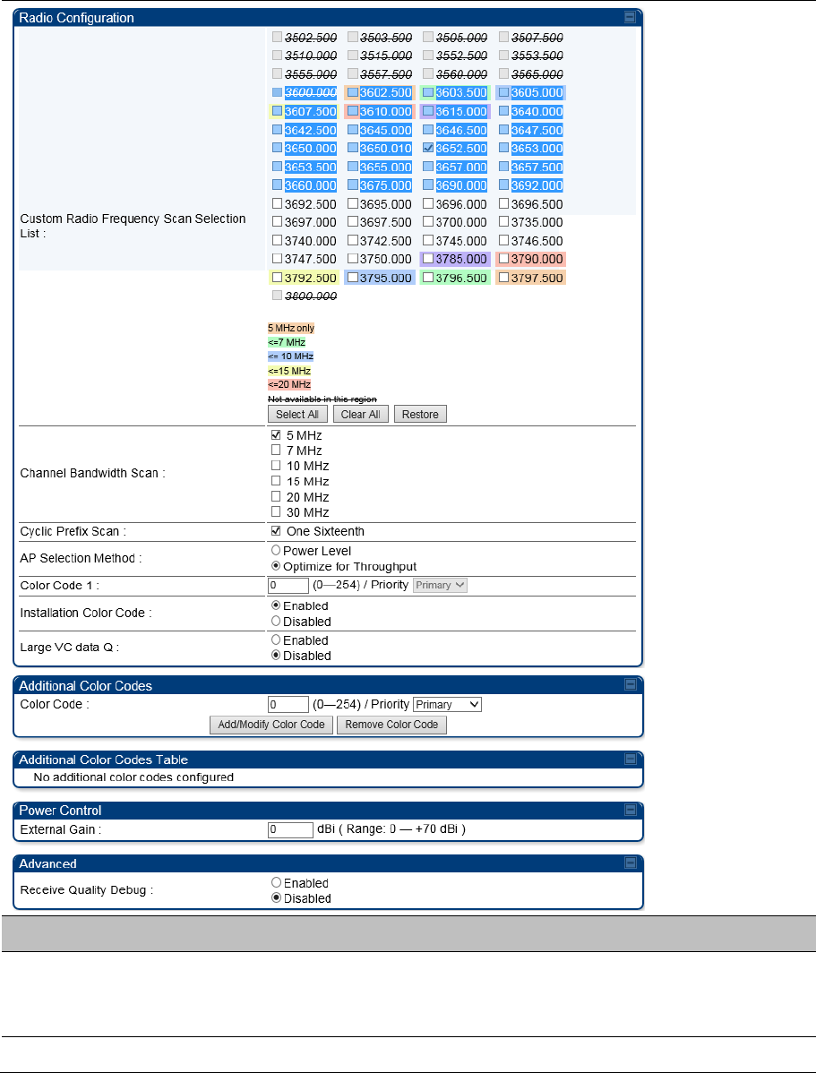
Chapter 7: Configuration Configuring radio parameters
Page 7-163
Radio page - PMP 450 SM 3.65 GHz
Table 153 PMP 450 SM Radio attributes – 3.65 GHz
Attribute Meaning
Custom Radio
Frequency Scan
Selection List
Check the frequencies that SM has to scan for AP transmissions. See Radio
Frequency Scan Selection List on page 7-169.
See Table 142 PMP 450i AP Radio attributes - 5 GHz on page 7-132.