Cambium Networks 50450M 5 GHz Point to Multipoint User MIMO Accesspoint User Manual 450 Platform User Guide
Cambium Networks Limited 5 GHz Point to Multipoint User MIMO Accesspoint 450 Platform User Guide
Contents
- 1. USER GUIDE P1
- 2. USER GUIDE P2
- 3. USER GUIDE P3
- 4. USER GUIDE P4
- 5. User manual
- 6. User Manual
- 7. USERS MANUAL PART1
- 8. USERS MANUAL PART2
- 9. USERS MANUAL PART3
- 10. USERS MANUAL PART4
- 11. USER MANUAL PART1
- 12. USER MANUAL PART2
- 13. USER MANUAL PART 3
- 14. USER MANUAL PART 4
- 15. USER MANUAL PT1
- 16. USER MANUAL PT2
- 17. USER MANUAL PT3
USER GUIDE P3

Page 7-71
Chapter 7: Configuration
This chapter describes how to use the web interface to configure the PMP/PTP 450 platform link.
This chapter contains the following topics:
Preparing for configuration on page 7-72
Connecting to the unit on page 7-73
Using the web interface on page 7-75
Quick link setup on page 7-81
Configuring IP and Ethernet interfaces on page 7-92
Upgrading the software version and using CNUT on page 7-135
General configuration on page 7-139
Configuring Unit Settings page on page 7-157
Setting up time and date on page 7-161
Configuring synchronization on page 7-163
Configuring security on page 7-165
Configuring radio parameters on page 7-192
Setting up SNMP agent on page 7-242
Configuring syslog on page 7-249
Configuring remote access on page 7-255
Monitoring the Link on page 7-256
Configuring quality of service on page 7-259
Installation Color Code on page 7-272
Zero Touch Configuration Using DHCP Option 66 on page 7-273
Configuring Radio via config file on page 7-279
Configuring a RADIUS server on page 7-281
Chapter 7: Configuration
Preparing for configuration
Page 7-72
Preparing for configuration
This section describes the checks to be performed before proceeding with unit configuration and
antenna alignment.
Safety precautions
All national and local safety standards must be followed while configuring the units and aligning
the antennas.
Warning
Ensure that personnel are not exposed to unsafe levels of RF energy. The units start to
radiate RF energy as soon as they are powered up. Respect the safety standards
defined in Compliance with safety standards on page 4-22, in particular the minimum
separation distances.
Observe the following guidelines:
Never work in front of the antenna when the ODU is powered.
Always power down the PSU before connecting or disconnecting the drop cable
from the PSU, ODU or LPU.
Regulatory compliance
All applicable radio regulations must be followed while configuring the units and aligning the
antennas. For more information, refer to Compliance with radio regulations on page 4-31.
Caution
If the system designer has provided a list of channels to be barred for TDWR radar
avoidance, the affected channels must be barred before the units are allowed to
radiate on site, otherwise the regulations will be infringed.
Attention
Si le concepteur du système a fourni une liste de canaux à interdire pour éviter les
radars TDWR, les cannaux concernées doivent être interdits avant que les unités sont
autorisées à émettre sur le site, sinon la réglementation peut être enfreinte.
Chapter 7: Configuration
Connecting to the unit
Page 7-73
Connecting to the unit
This section describes how to connect the unit to a management PC and power it up.
Configuring the management PC
Use this procedure to configure the local management PC to communicate with the PMP/PTP 450
platform.
Procedure 9 Configuring the management PC
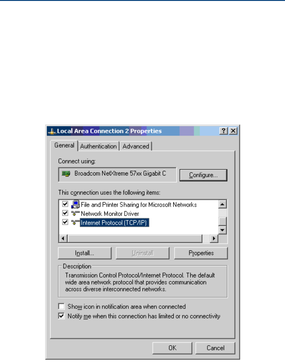
1
Select Properties for the Ethernet port. In Windows 7 this is found in Control Panel
> Network and Internet > Network Connections > Local Area Connection.
2
Select Internet Protocol (TCP/IP):
3
Click Properties.
Chapter 7: Configuration
Connecting to the unit
Page 7-74
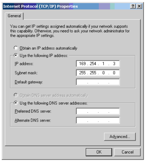
4
Enter an IP address that is valid for the 169.254.X.X network, avoiding 169.254.0.0
and 169.254.1.1. A good example is 169.254.1.3:
5
Enter a subnet mask of 255.255.0.0. Leave the default gateway blank.
Connecting to the PC and powering up
Use this procedure to connect a management PC and power up the PMP/PTP 450 platform.
Procedure 10 Connecting to the PC and powering up
1
Check that the ODU and PSU are correctly connected.
2
Connect the PC Ethernet port to the LAN port of the PSU using a standard (not
crossed) Ethernet cable.
3
Apply mains or battery power to the PSU. The green Power LED should illuminate
continuously.
4
After about several seconds, check that the orange Ethernet LED starts with 10 slow
flashes.
5
Check that the Ethernet LED then illuminates continuously.
Chapter 7: Configuration
Using the web interface
Page 7-75
Using the web interface
This section describes how to log into the PMP/PTP 450 platform web interface and use its menus.
Logging into the web interface
Use this procedure to log into the web interface as a system administrator.
Procedure 11 Logging into the web interface
1
Start the web browser from the management PC.
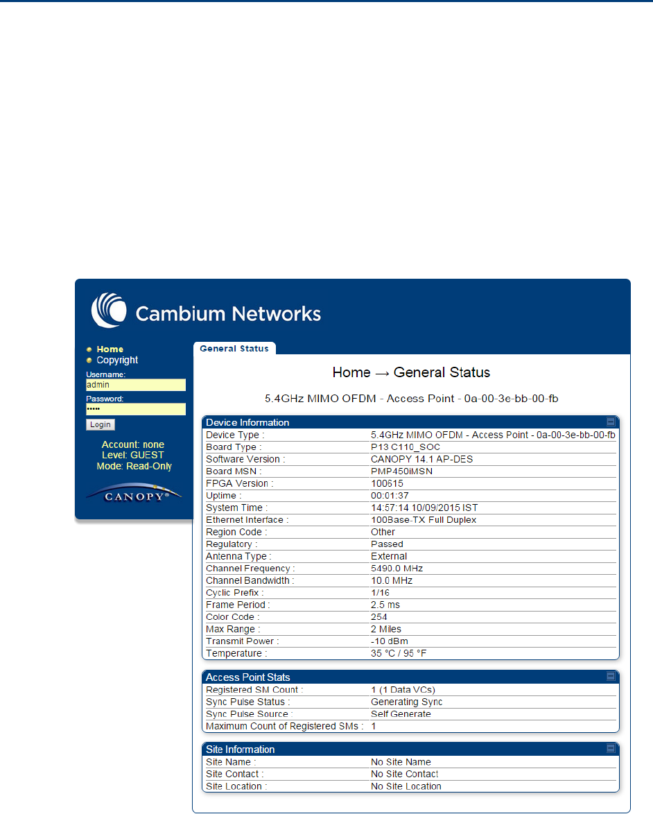
2
Type the IP address of the unit into the address bar. The factory default IP address is
169.254.1.1. Press ENTER. The web interface menu and System Summary page are
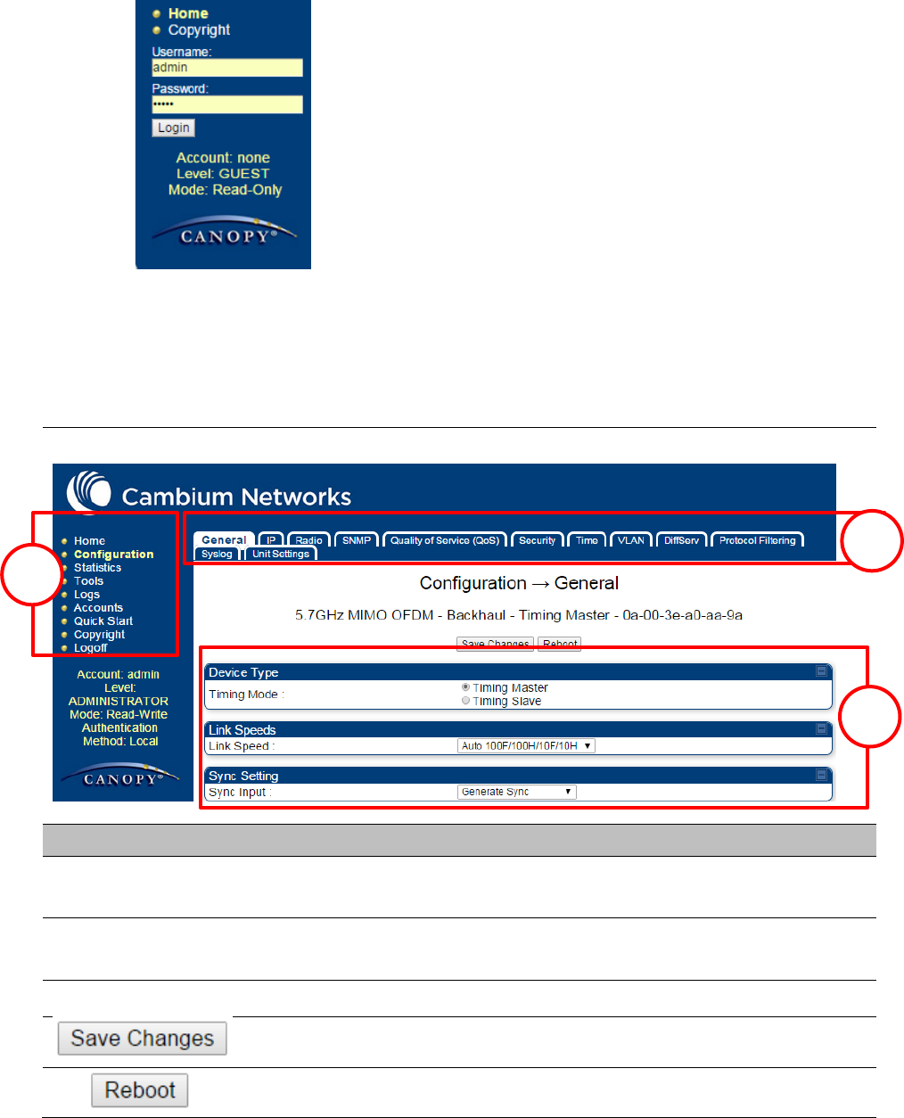
displayed:
Chapter 7: Configuration
Using the web interface
Page 7-76
3
On left hand side of home page, the login information is displayed:
4
Enter Username (factory default username is admin) and Password (factory default password
is admin) and click Login.
Web GUI
Field Name
Description
Main Manu
Click an option in side navigation bar (area marked as “1”). Multiple
options in sub-navigation bars appear
Menu Option
Click top sub-navigation bar to choose one configuration page (area
marked as “2”)
Parameter
To configure the parameters (e.g. area marked as “3”)
Press "Save Changes" to confirm and save the changes
To reboot the ODU
1
1
2
3
Chapter 7: Configuration
Using the web interface
Page 7-77
Using the menu options
Use the menu navigation bar in the left panel to navigate to each web page. Some of the menu
options are only displayed for specific system configurations. Use Table 83 to locate information
about using each web page.
Table 83 Menu options and web pages
Main
menu
Menu options
Applicable
module
Description
All
Viewing General Status on page 9-2
AP, BHM
Viewing Session Status on page 9-16
All
Interpreting messages in the Event
Log on page 9-23
AP, BHM
Viewing the Network Interface on
page 9-25
All
Viewing the Layer 2 Neighbors on
page 9-26
All
General configuration on page 7-139
All
Configuring IP and Ethernet interfaces
on page 7-92
All
Configuring radio parameters on page
7-193
All
Setting up SNMP agent on page 7-242
All
Configuring quality of service on page
7-259
All
Configuring security on page 7-165
AP, BHM
Setting up time and date
Time page of PMP/PTP 450 platform
AP/BHM on page 7-161
All
VLAN configuration for PMP on page
7-114
VLAN configuration for PTP on page
7-124
Event Log
Network Interface
General
IP
Radio
SNMP
Qaulity of Service (QoS)
Security
Time
VLAN
Layer 2 Neighbors
Session Status
General Status
Chapter 7: Configuration
Using the web interface
Page 7-78
Main
menu
Menu options
Applicable
module
Description
All
IPv4 and IPv6 Prioritization on page 7-
131
All
Filtering protocols and ports on page
7-132
All
Configuring syslog on page 7-249
All
Configuring Unit Settings page on
page 7-157
All
Viewing the Scheduler statistics on
page 9-27
AP, BHM
Viewing list of Registration Failures
statistics on page 9-29
All
Interpreting Bridge Control Block
statistics on page 9-52
All
Interpreting Bridging Table statistics
on page 9-30
All
Interpreting Ethernet statistics on
page 9-32
All
Interpreting RF Control Block statistics
on page 9-35
All
Interpreting VLAN statistics on page
9-36
All
Interpreting Data VC statistics on page
9-38
AP, BHM
Interpreting Throughput statistics on
page 9-40
SM
Interpreting Filter statistics on page 9-
46
SM
Viewing ARP statistics on page 9-47
All
Interpreting Overload statistics on
page 9-43
All
Interpreting syslog statistics on page
9-57
SM
Interpreting Translation Table
statistics on page 9-31
DiffServ
Protocol Filtering
Syslog
Unit Setting
Scheduler
Registration Failures
Bridge Control Block
Bridging Table
Ethernet
Radio
VLAN
Data VC
Throughput
Filter
ARP
Overload
Syslog Statistics
Translation Table
Chapter 7: Configuration
Using the web interface
Page 7-79
Main
menu
Menu options
Applicable
module
Description
SM
Interpreting DHCP Relay statistics on
page 9-44
SM
Viewing NAT statistics on page 9-47
SM
Viewing NAT DHCP Statistics on page
9-49
AP
Interpreting Pass Through Statistics
on page 9-54
AP
Interpreting Sync Status statistics on
page 9-50
SM
Interpreting PPPoE Statistics for
Customer Activities on page 9-51
All
Interpreting SNMPv3 Statistics on
page 9-55
Interpreting SNMPv3 Statistics on
page 9-55
All
Using the Link Capacity Test tool on
page 8-21
All
Spectrum Analyzer tool on page 8-3
All
Remote Spectrum Analyzer tool on
page 8-12
SM, BHS
Using AP Evaluation tool on page 8-27
Using BHM Evaluation tool on page 8-
31
AP
Using the Subscriber Configuration
tool on page 8-39
AP, BHM
Using the OFDM Frame Calculator
tool on page 8-35
SM
Using BER Results tool on page 8-45
SM, BHS
Using the Alignment Tool on page 8-
15
AP
Using the Link Status tool on page 8-
40
AP
Using the Sessions tool on page 8-46
Link Capacity Test
Spectrum Analyzer
Remote Spectrum Analyzer
OFDM Frame Calculator
Link Status
Sessions
AP/BHM Evaluation
BER results
DHCP Relay
NAT Stats
NAT DHCP
Sync Status
PPPoE
SNMPv3 Statistics
Pass Through Statistics
Frame Utilization
Alignment Tool
Subscriber Configuration
Chapter 7: Configuration
Using the web interface
Page 7-80
Main
menu
Menu options
Applicable
module
Description
Changing a User Setting on page 7-
167
Adding a User for Access to a module
on page 7-166
Deleting a User from Access to a
module on page 7-167
Users account on page 7-168
AP, BHM
Quick link setup on page 7-81
AP, BHM
Quick link setup on page 7-81
AP, BHM
Quick link setup on page 7-81
AP, BHM
Quick link setup on page 7-81
AP, BHM
Quick link setup on page 7-81
AP, BHM
Quick link setup on page 7-81
SM
The PDA web-page includes 320 x 240
pixel formatted displays of
information important to installation
and alignment for installers using
legacy PDA devices. All device web
pages are compatible with touch
devices such as smart phones and
tablets.
SM
SM
SM
SM
All
The Copyright web-page displays
pertinent device copyright
information.
All
Change User Setting
Add user
Delete User
User
Copyright Notices
Quick Start
Synchronization
LAN IP Address
Region Settings
Radio Carrier Frequency
Review and Save Configuration
Quick Status
Spectrum Results (PDA)
Information
BHM Evaluation
AIM
Chapter 7: Configuration
Quick link setup
Page 7-81
Quick link setup
This section describes how to use the Quick Start Wizard to complete the essential system
configuration tasks that must be performed on a PMP/PTP configuration.
Note
If the IP address of the AP or BHM is not known, See Radio recovery mode on page 1-
22.
Initiating Quick Start Wizard
Applicable products
PMP :
AP
PTP:
BHM
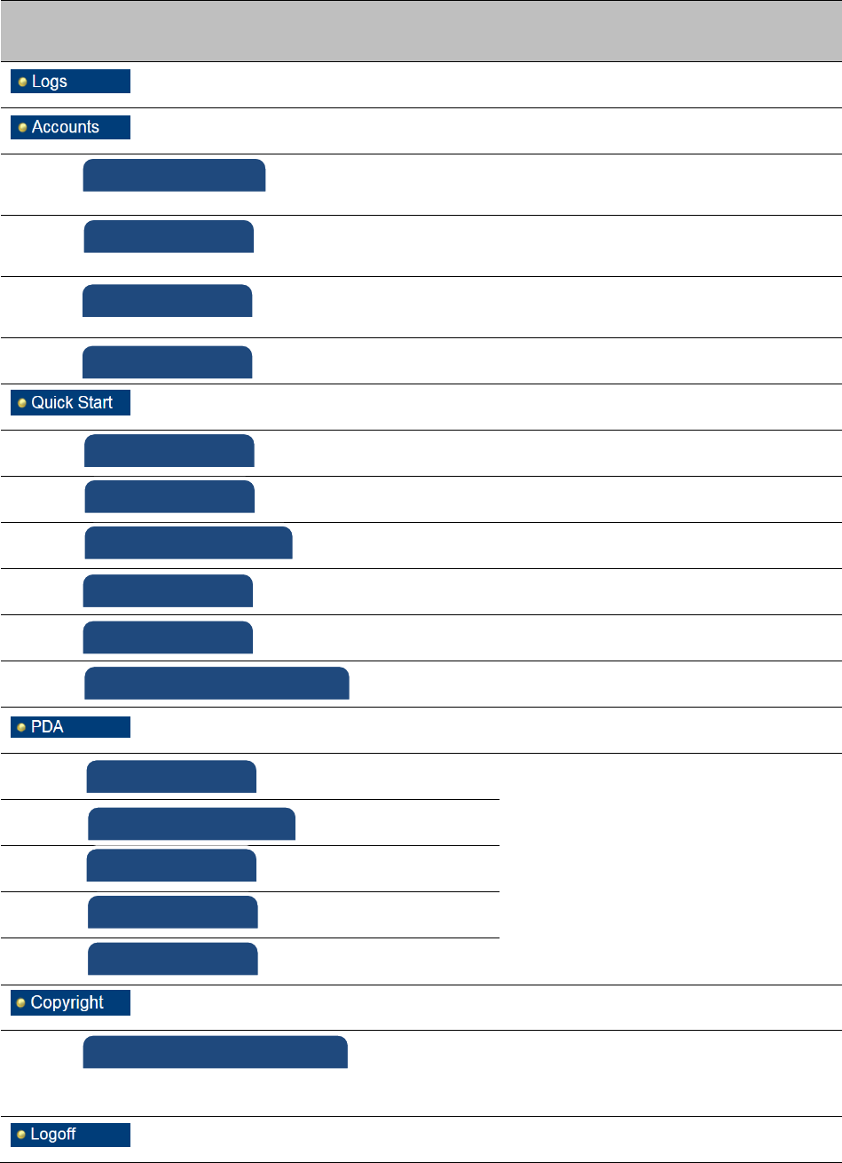
To start with Quick Start Wizard: after logging into the web management interface click the Quick
Start button on the left side of main menu bar. The AP/BHM responds by opening the Quick Start
page.
Figure 99 Disarm Installation page (top and bottom of page shown)
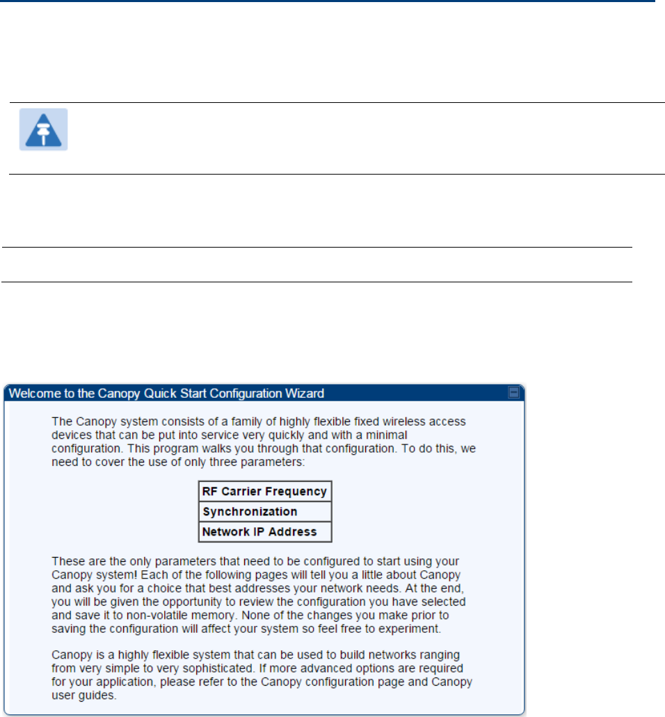
Quick Start is a wizard that helps you to perform a basic configuration that places an AP/BHM into
service. Only the following parameters must be configured:
Region Code
RF Carrier Frequency
Synchronization
LAN (Network) IP Address
Chapter 7: Configuration
Quick link setup
Page 7-82
In each Quick Start page, you can
specify the settings to satisfy the requirements of the network.
review the configuration selected.
save the configuration to non-volatile memory.
Procedure 12 Quick start wizard
1
At the bottom of the Quick Start tab, click the Go To Next Page button.
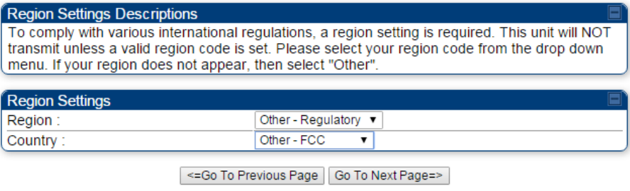
2
From the pull-down menu, select the region in which the AP will operate.
Figure 100 Regional Settings tab of AP/BHM
3
Click the Go To Next Page button.
Chapter 7: Configuration
Quick link setup
Page 7-83
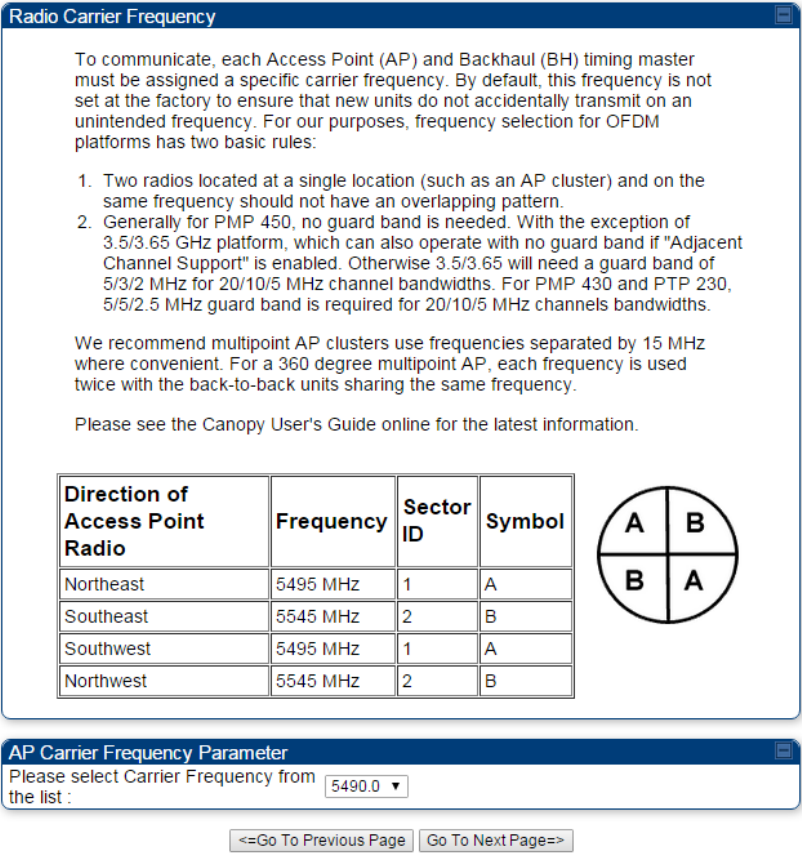
4
From the pull-down menu, select a frequency for the test.
Figure 101 Radio Carrier Frequency tab of AP/BHM
5
Click the Go To Next Page button.
Chapter 7: Configuration
Quick link setup
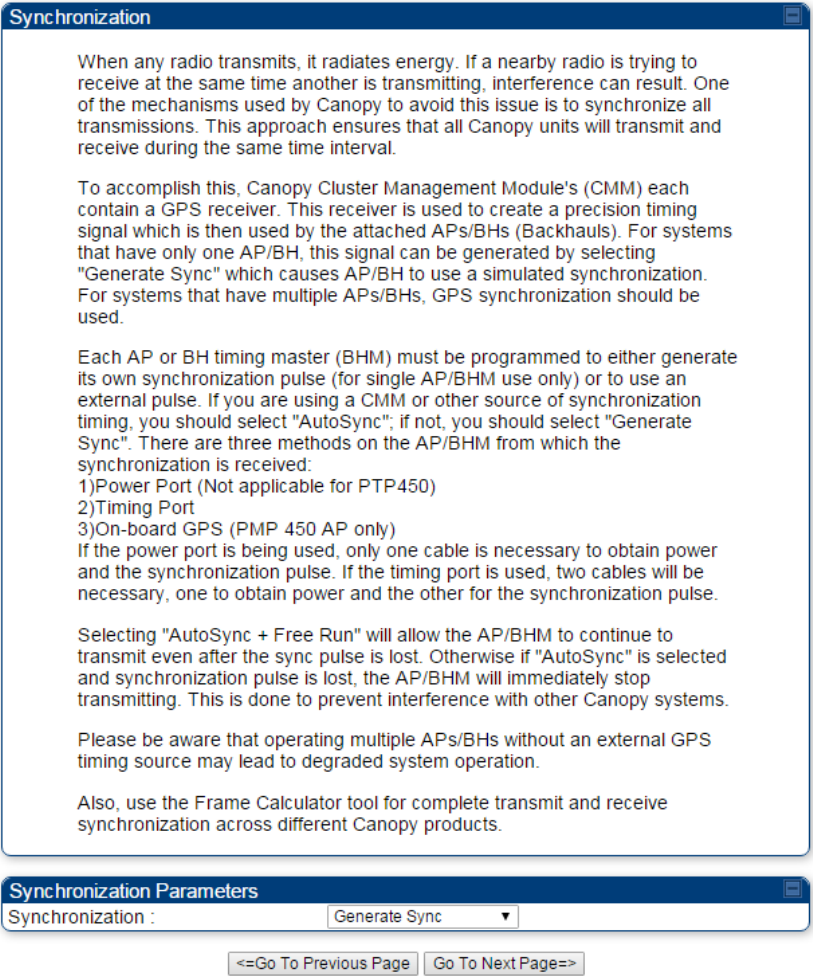
Page 7-84
6
At the bottom of this tab, select Generate Sync Signal.
Figure 102 Synchronization tab of AP/BHM
7
Click the Go To Next Page button.
Chapter 7: Configuration
Quick link setup
Page 7-85
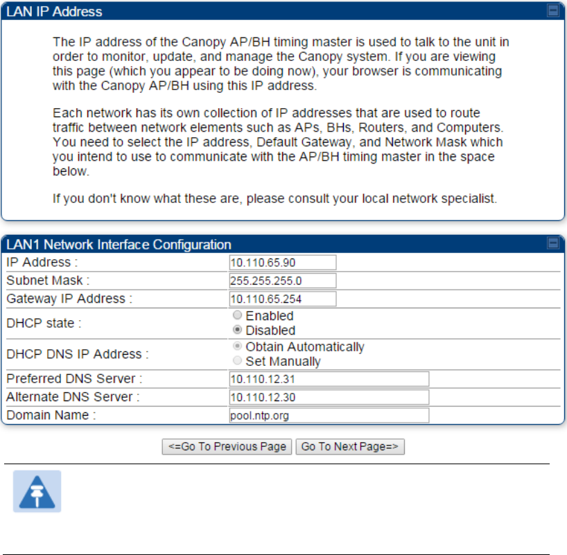
8
At the bottom of the IP address configuration tab, either
specify an IP Address, a Subnet Mask, and a Gateway IP Address for management of the
AP and leave the DHCP state set to Disabled.
set the DHCP state to Enabled to have the IP address, subnet mask, and gateway IP
address automatically configured by a domain name server (DNS).
Figure 103 LAN IP Address tab of the AP/BHM
Note
Cambium encourages you to experiment with the interface. Unless you
save a configuration and reboot the AP after you save the configuration,
none of the changes are affected.
9
Click the Go To Next Page => button.
Chapter 7: Configuration
Quick link setup
Page 7-86
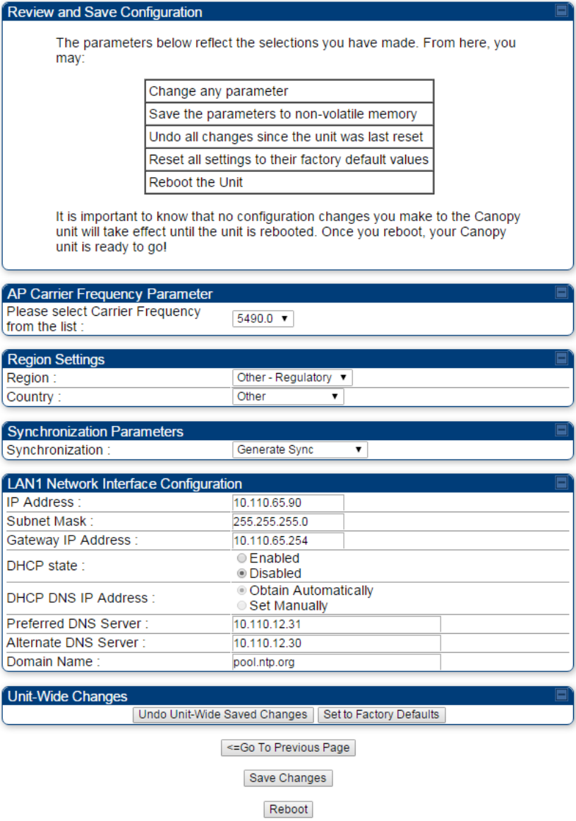
10
Ensure that the initial parameters for the AP are set as you intended.
Figure 104 Review and Save Configuration tab of the AP/BHM
11
Click the Save Changes button.
12
Click the Reboot button.
RESULT: The AP responds with the message Reboot Has Been Initiated…
Chapter 7: Configuration
Quick link setup
Page 7-87
13
Wait until the indicator LEDs are not red.
14
Trigger your browser to refresh the page until the AP redisplays the General Status tab.
15
Wait until the red indicator LEDs are not lit.
Configuring time settings
Applicable products
PMP :
AP
PTP:
BHM
To proceed with the test setup, click the Configuration link on the left side of the General Status
page. When the AP responds by opening the Configuration page to the General page, click the
Time tab.
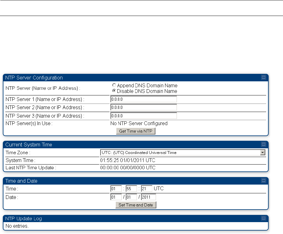
Figure 105 Time tab of the AP/BHM
To have each log in the AP/BHM correlated to a meaningful time and date, either a reliable network
element must pass time and date to the AP/BHM or you must set the time and date whenever a
power cycle of the AP/BHM has occurred. A network element passes time and date in any of the
following scenarios:
A connected CMM4 passes time and date (GPS time and date, if received).
A separate NTP server is addressable from the AP/BHM.
If the AP/BHM should obtain time and date from a CMM4, or a separate NTP server, enter the IP
address of the CMM4 or NTP server on this tab. To force the AP/BHM to obtain time and date
before the first (or next) 15-minute interval query of the NTP server, click Get Time through NTP.
Chapter 7: Configuration
Quick link setup
Page 7-88
If you enter a time and date, the format for entry is
Figure 106 Time and date entry formats
Time :
hh
/
mm
/
ss
Date :
MM
/
dd
/
yyyy
where
hh
represents the two-digit hour in the range 00 to 24
mm
represents the two-digit minute
ss
represents the two-digit second
MM
represents the two-digit month
dd
represents the two-digit day
yyyy
represents the four-digit year
Proceed with the time setup as follows.
Procedure 13 Entering AP/BHM time setup information
1
Enter the appropriate information in the format shown above.
2
Then click the Set Time and Date button.
Note
The time displayed at the top of this page is static unless your browser
is set to automatically refresh
Powering the SM/BHS for test
Procedure 14 Powering the SM/BHS for test
1
In one hand, securely hold the top (larger shell) of the SM/BHS. With the other hand,
depress the lever in the back of the base cover (smaller shell). Remove the base
cover.
2
Plug one end of a CAT 5 Ethernet cable into the SM PSU port
3
Plug the other end of the Ethernet cable into the jack in the pig tail that hangs from
the power supply
4
Roughly aim the SM/BHS toward the AP/BHM
5
Plug the power supply into an electrical outlet
Warning
From this point until you remove power from the AP/BHM, stay at
least as far from the AP/BHM as the minimum separation distance
specified in Calculated distances and power compliance margins.
6
Repeat the foregoing steps for each SM/BHS that you wish to include in the test.

Chapter 7: Configuration
Quick link setup
Page 7-89
Viewing the Session Status of the AP/BHM to determine test
registration
Once the SMs/BHS under test are powered on, return to the computing device to determine if the
SM/BHS units have registered to the AP/BHM.
Note
In order for accurate power level readings to be displayed, traffic must be present on
the radio link.
The Session Status tab provides information about each SM/BHS that has registered to
the AP/BHM. This information is useful for managing and troubleshooting a system.
All information that you have entered in the Site Name field of the SM/BHS displays in the Session
Status tab of the linked AP/BHM.
The Session Status tab also includes the current active values on each SM( or BHS) (LUID) for MIR,
and VLAN, as well as the source of these values (representing the SM/BHS itself, Authentication
Server, or the AP/BHM and cap, if any—for example, APCAP as shown above).. As an SM/BHS
registers to the AP/BHM, the configuration source that this page displays for the associated LUID
may change. After registration, however, the displayed source is stable and can be trusted.
Idle subscribers may be included or removed from the session status display by enabling or
disabling, respectively, the Show Idle Sessions parameter. Enabling or disabling this parameter
only affects the GUI display of subscribers, not the registration status.
The SessionStatus.xml hyperlink allows user to export session status page from web management
interface of AP/BHM. The session status page will be exported in xml file.
Chapter 7: Configuration
Quick link setup
Page 7-90
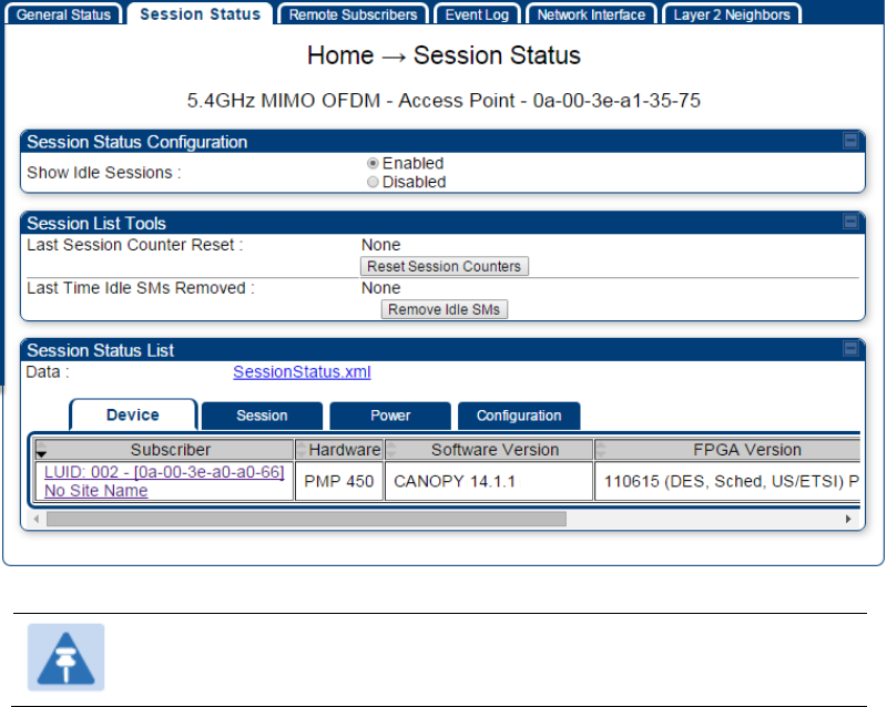
Procedure 15 Viewing the AP Session Status page
1
On the AP web management GUI, navigate to Home, Session Status:
Figure 107 Session Status tab of AP
Note
Session status page for BHM is same as AP.
2
Verify that for each SM (or BHS) MAC address (printed on the SM/BHS housing) the
AP/BHM has established a registered session by verifying the “State” status of each
entry.
The Session Status page of the AP/BHM is explained in Table 84.
Chapter 7: Configuration
Quick link setup
Page 7-91
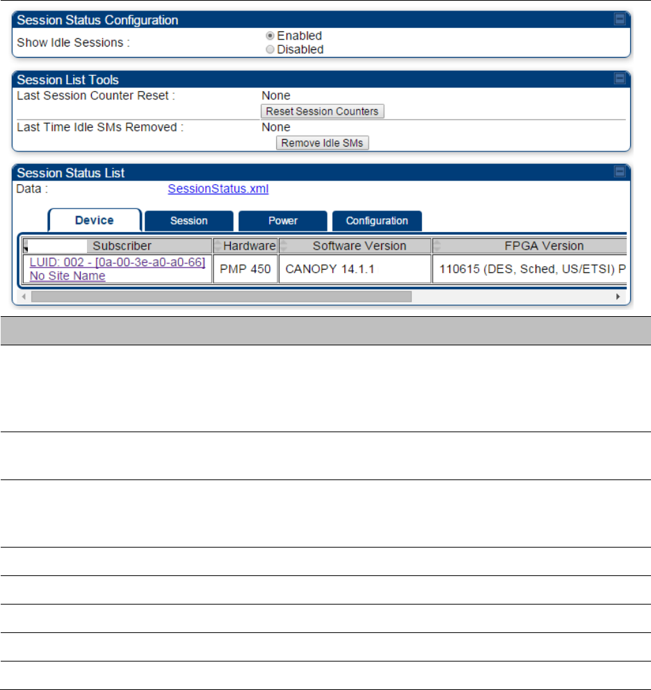
Table 84 Session Status Attributes – AP
Attribute
Meaning
Show Idle Sessions
Idle subscribers may be included or removed from the session status
display by enabling or disabling, respectively, the Show Idle Sessions
parameter. Enabling or disabling this parameter only affects the GUI
display of subscribers, not the registration status.
Last Session Counter
Reset
This field displays date and time stamp of last session counter reset.
Last Time Idle SMs
Removed
This field displays date and time stamp of last Idle SMs Removed. On
click of “Remove Idle SMs” button, all the SMs which are in Idle state
are flushed out.
Data
See Exporting Session Status page of AP/BHM on page 7-270
Device tab
See Device tab on page 9-16
Session tab
See Session tab on page 9-17
Power tab
See Power tab on page 9-19
Configuration tab
See Configuration tab on page 9-20

Chapter 7: Configuration
Configuring IP and Ethernet interfaces
Page 7-92
Configuring IP and Ethernet interfaces
This task consists of the following sections:
Configuring the IP interface on page 7-93
Auxiliary port on page 7-96
NAT, DHCP Server, DHCP Client and DMZ on page 7-97
IP interface with NAT disabled on page 7-102
IP interface with NAT enabled on page
NAT tab with NAT disabled on page 7-105
NAT tab with NAT enabled on page 7-108
NAT DNS Considerations on page 7-113
DHCP – BHS on page 7-114
VLAN configuration for PMP on page 7-114
VLAN page of AP on page 7-117
VLAN page of SM on page 7-120
VLAN Membership tab of SM on page 7-124
VLAN configuration for PTP on page 7-124
NAT Port Mapping tab - SM on page 7-113
Chapter 7: Configuration
Configuring IP and Ethernet interfaces
Page 7-93
Configuring the IP interface
The IP interface allows users to connect to the PMP/PTP 450 platform web interface, either from a
locally connected computer or from a management network.
Applicable products
PMP :
AP
SM
PTP:
BHM
BMS
To configure the IP interface, follow these instructions:
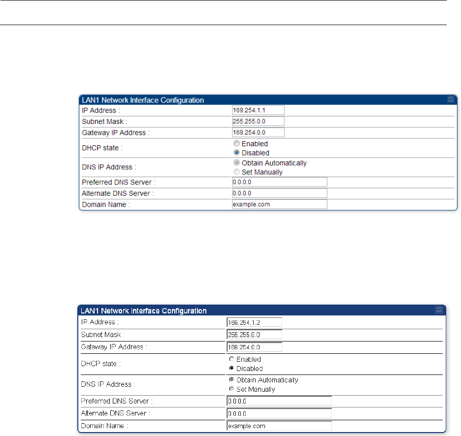
Procedure 16 Configuring the AP/BHM IP interface
1
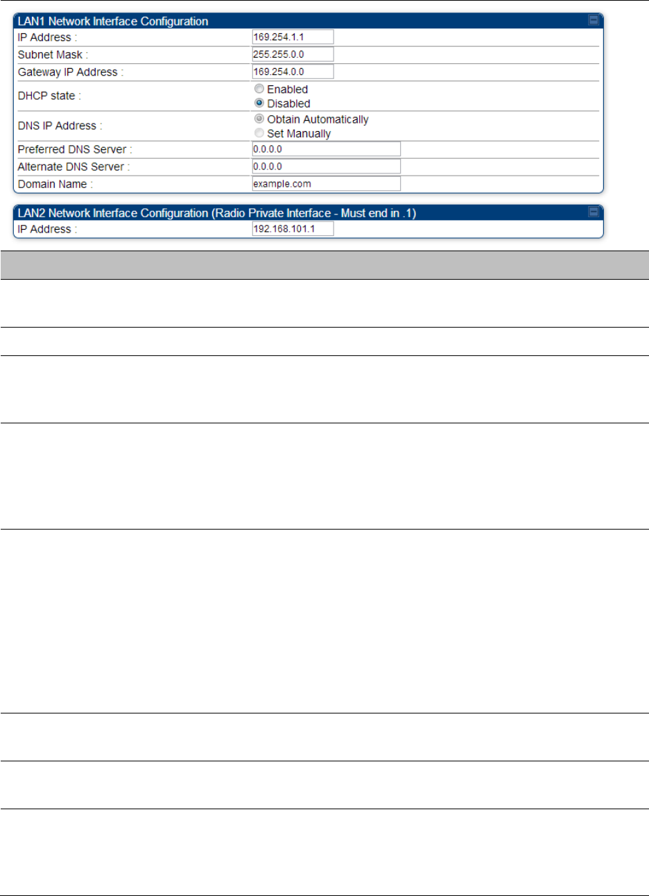
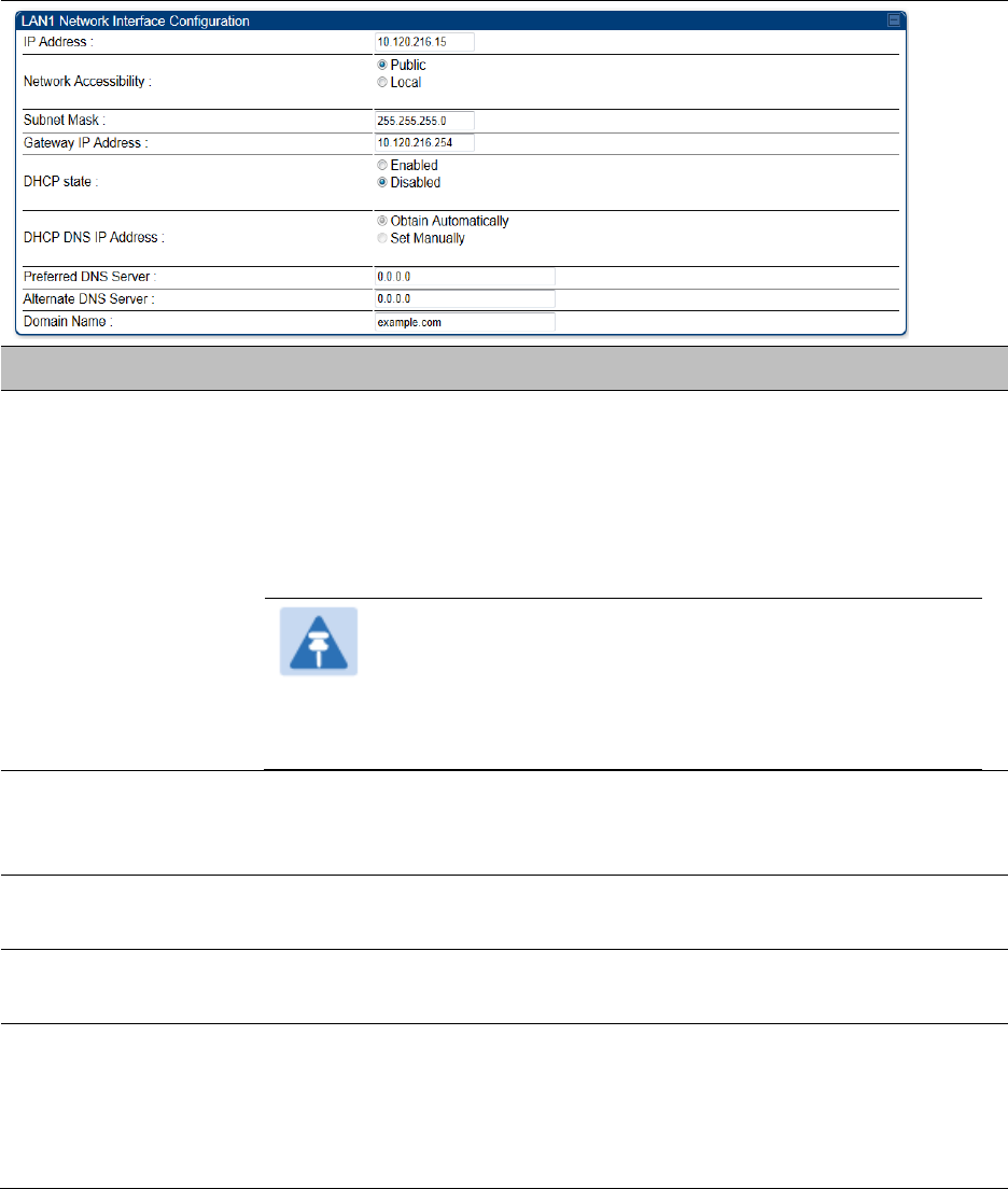
Select menu option Configuration > IP. The LAN configuration page is displayed:
2
Update IP Address, Subnet Mask and Gateway IP Address to meet network
requirements (as specified by the network administrator).
3
Review the other IP interface attributes and update them, if necessary (see Table 85 IP
interface attributes).
4
Click Save. “Reboot Required” message is displayed:
5
Click Reboot.
The IP page of AP/SM/BHM/BHS is explained in Table 85.
Chapter 7: Configuration
Configuring IP and Ethernet interfaces
Page 7-94
Table 85 IP interface attributes
Attribute
Meaning
IP Address
Internet Protocol (IP) address. This address is used by family of Internet
protocols to uniquely identify this unit on a network.
Subnet Mask
Defines the address range of the connected IP network.
The IP address of a computer on the current network that acts as a
gateway. A gateway acts as an entrance and exit to packets from and to
other networks.
DHCP state
If Enabled is selected, the DHCP server automatically assigns the IP
configuration (IP address, subnet mask, and gateway IP address) and the
values of those individual parameters (above) are not used. The setting
of this DHCP state parameter is also viewable (read only), in the Network
Interface tab of the Home page.
DNS IP Address
Canopy devices allow for configuration of a preferred and alternate DNS
server IP address either automatically or manually. Devices must set
DNS server IP address manually when DHCP is disabled for the
management interface of the device. DNS servers may be configured
automatically from the DHCP response when DHCP is enabled for the
management interface of the device. Optionally devices may be
configured to set the DNS server IP address manually when DHCP is
enabled for the management interface. The default DNS IP addresses are
0.0.0.0 when configured manually.
Preferred DNS
Server
The first address used for DNS resolution.
Alternate DNS
Server
If the Preferred DNS server cannot be reached, the Alternate DNS Server
is used.
Domain Name
The operator’s management domain name may be configured for DNS.
The domain name configuration can be used for configuration of the
servers in the operator’s network. The default domain name is
example.com, and is only used if configured as such.

Chapter 7: Configuration
Configuring IP and Ethernet interfaces
Page 7-95
LAN2 Network
Interface
Configuration (Radio
Private Interface) – IP
Address
It is recommended not to change this parameter from the default
AP/BHM private IP address of 192.168.101.1. A /24 CIDR subnet is used to
communicate with each of the SMs/BHS that are registered. The AP/BHM
uses a combination of the private IP and the LUID (logical unit ID) of the
SM/BHS.
It is only displayed for AP and BHM.
Table 86 SM/BHS private IP and LUID
SM/BHS
LUID
Private IP
First SM/BHS registered
2
192.168.101.2
Second SM/BHS registered
3
192.168.101.3
Chapter 7: Configuration
Configuring IP and Ethernet interfaces
Page 7-96
Auxiliary port
An additional Ethernet port labeled “Aux” for Auxiliary port is implemented for downstream
traffic. This feature is supported only for PTP/PMP 450i series devices.
To enable the Aux port, follow these instructions:
Procedure 17 Enabling Aux port interface
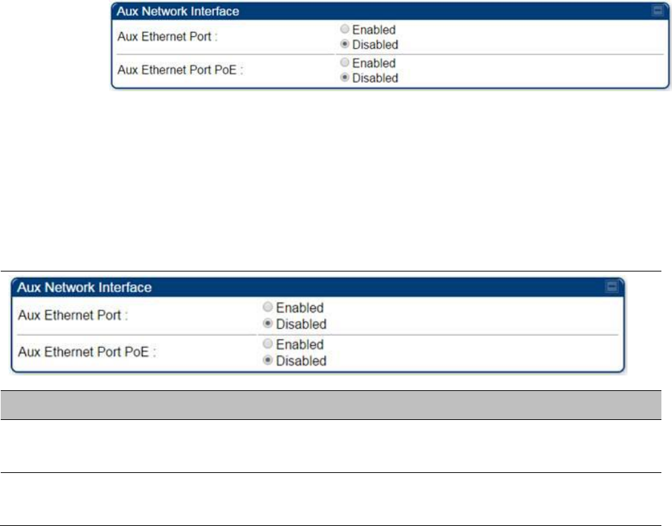
1
Select menu option Configuration > IP > Aux Network Interface tab.:
2
Click Enable button of Aux Ethernet Port parameter to enable Aux Ethernet port
3
Click Enable button of Aux Ethernet Port PoE parameter to enable Aux port PoE out.
4
Click Save. “Reboot Required” message is displayed.
5
Click Reboot.
Table 87 Aux port attributs
Attribute
Meaning
Aux Ethernet Port
Enabled: Data is enabled for Auxiliary port
Disabled: Data is disabled for Auxiliary port
Aux Ethernet Port
PoE
Enabled: PoE out is enable for Auxiliary port
Disabled: PoE out is disabled for Auxiliary port
By disabling this feature, the data at the Auxiliary port will be disabled.

Chapter 7: Configuration
Configuring IP and Ethernet interfaces
Page 7-97
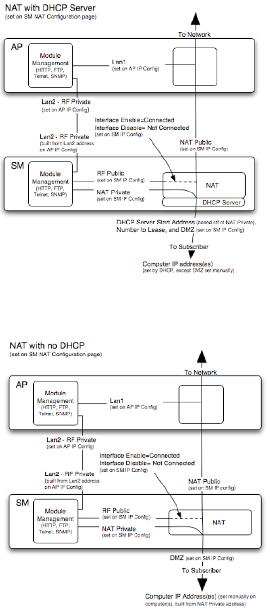
NAT, DHCP Server, DHCP Client and DMZ
Applicable products
PMP :
SM
The system provides NAT (Network Address Translation) for SMs in the following combinations of
NAT and DHCP (Dynamic Host Configuration Protocol):
NAT Disabled
NAT with DHCP Client (DHCP selected as the Connection Type of the WAN interface) and DHCP
Server
NAT with DHCP Client(DHCP selected as the Connection Type of the WAN interface)
NAT with DHCP Server
NAT without DHCP
NAT
NAT isolates devices connected to the Ethernet or wired side of a SM from being seen directly
from the wireless side of the SM. With NAT enabled, the SM has an IP address for transport traffic
(separate from its address for management), terminates transport traffic and allows you to assign
a range of IP addresses to devices that are connected to the Ethernet or wired side of the SM.
In the Cambium system, NAT supports many protocols, including HTTP, ICMP (Internet Control
Message Protocols), and FTP (File Transfer Protocol). For virtual private network (VPN)
implementation, L2TP over IPSec (Level 2 Tunneling Protocol over IP Security) and PPTP (Point to
Point Tunneling Protocol) are supported.
Note
When NAT is enabled, a reduction in throughput is introduced in the system (due to
processing overhead).
DHCP
DHCP enables a device to be assigned a new IP address and TCP/IP parameters, including a default
gateway, whenever the device reboots. Thus DHCP reduces configuration time, conserves IP
addresses, and allows modules to be moved to a different network within the Cambium system.
In conjunction with the NAT features, each SM provides the following:
A DHCP server that assigns IP addresses to computers connected to the SM by Ethernet
protocol.
A DHCP client that receives an IP address for the SM from a network DHCP server.
Chapter 7: Configuration
Configuring IP and Ethernet interfaces
Page 7-98
DMZ
In conjunction with the NAT features, a DMZ (Demilitarized Zone) allows the allotment of one IP
address behind the SM for a device to logically exist outside the firewall and receive network
traffic. The first three octets of this IP address must be identical to the first three octets of the NAT
private IP address.
A DHCP server that assigns IP addresses to computers connected to the SM by Ethernet
protocol.
A DHCP client that receives an IP address for the SM from a network DHCP server.
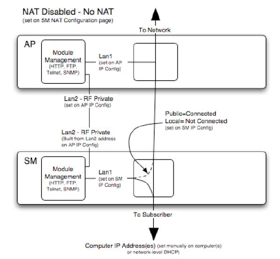
NAT Disabled
The NAT Disabled implementation is illustrated in Figure 108.
Figure 108 NAT disabled implementation
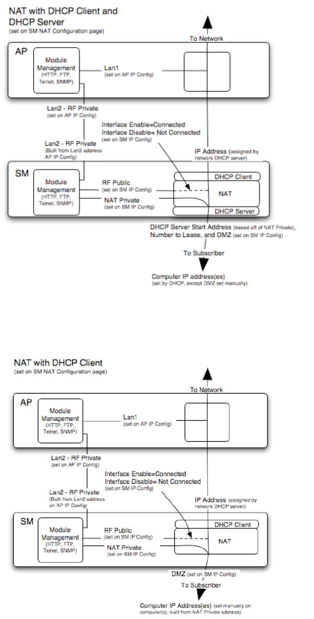
NAT with DHCP Client and DHCP Server
The NAT with DHCP Client and DHCP server is illustrated in Figure 109.
Chapter 7: Configuration
Configuring IP and Ethernet interfaces
Page 7-99
Figure 109 NAT with DHCP client and DHCP server implementation
NAT with DHCP Client
Figure 110 NAT with DHCP client implementation
Chapter 7: Configuration
Configuring IP and Ethernet interfaces
Page 7-100
NAT with DHCP Server
Figure 111 NAT with DHCP server implementation
NAT without DHCP
Figure 112 NAT without DHCP implementation
Chapter 7: Configuration
Configuring IP and Ethernet interfaces
Page 7-101
NAT and VPNs
VPN technology provides the benefits of a private network during communication over a public
network. One typical use of a VPN is to connect employees remotely (who are at home or in a
different city), with their corporate network through a public Internet. Any of several VPN
implementation schemes is possible. By design, NAT translates or changes addresses, and thus
interferes with a VPN that is not specifically supported by a given NAT implementation.
With NAT enabled, SM supports L2TP over IPSec (Level 2 Tunneling Protocol over IP Security)
VPNs and PPTP (Point to Point Tunneling Protocol) VPNs. With NAT disabled, SM supports all
types of VPNs.
Chapter 7: Configuration
Configuring IP and Ethernet interfaces
Page 7-102
IP interface with NAT disabled - SM
The IP page of SM with NAT disabled is explained in Table 88.
Table 88 IP attributes - SM with NAT disabled
Attribute
Meaning
IP Address
Enter the non-routable IP address to associate with the Ethernet
connection on this SM. (The default IP address from the factory is
169.254.1.1.) If you forget this parameter, you must both:
physically access the module.
use recovery mode to access the module configuration parameters
at 169.254.1.1. See Radio recovery mode on page 1-22
Note
Note or print the IP settings from this page. Ensure that
you can readily associate these IP settings both with the
module and with the other data that you store about the
module.
Network
Accessibility
Specify whether the IP address of the SM must be visible to only a
device connected to the SM by Ethernet (Local) or be visible to the
AP/BHM as well (Public).
Subnet Mask
Enter an appropriate subnet mask for the SM to communicate on the
network. The default subnet mask is 255.255.0.0.
Gateway IP Address
Enter the appropriate gateway for the SM to communicate with the
network. The default gateway is 169.254.0.0.
DHCP state
If you select Enabled, the DHCP server automatically assigns the IP
configuration (IP address, subnet mask, and gateway IP address) and the
values of those individual parameters (above) are not used. The setting
of this DHCP state parameter is also viewable, but not settable, in the
Network Interface tab of the Home page.

Chapter 7: Configuration
Configuring IP and Ethernet interfaces
Page 7-103
In this tab, DHCP State is settable only if the Network Accessibility
parameter in the IP tab is set to Public. This parameter is also settable in
the NAT tab of the Configuration web page, but only when NAT is
enabled.
If the DHCP state parameter is set to Enabled in the Configuration > IP
sub-menu of the SM/BHS, do not check the BootpClient option for Packet
Filter Types in its Protocol Filtering tab, because doing so can block the
DHCP request. (Filters apply to all packets that leave the SM via its RF
interface, including those that the SM itself generates.) If you want to
keep DHCP enabled and avoid the blocking scenario, select the Bootp
Server option instead. This will result in responses being appropriately
filtered and discarded.
DHCP DNS IP
Address
Canopy devices allow for configuration of a preferred and alternate DNS
server IP address either automatically or manually. Devices must set
DNS server IP address manually when DHCP is disabled for the
management interface of the device. DNS servers may be configured
automatically from the DHCP response when DHCP is enabled for the
management interface of the device. Optionally devices may be
configured to set the DNS server IP address manually when DHCP is
enabled for the management interface. The default DNS IP addresses are
0.0.0.0 when configured manually.
Preferred DNS
Server
The first DNS server used for DNS resolution.
Alternate DNS
Server
The second DNS server used for DNS resolution.
Domain Name
The operator’s management domain name may be configured for DNS.
The domain name configuration can be used for configuration of the
servers in the operator’s network. The default domain name is
example.com, and is only used if configured as such.
Chapter 7: Configuration
Configuring IP and Ethernet interfaces
Page 7-104
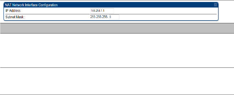
IP interface with NAT enabled - SM
The IP page of SM with NAT enabled is explained in Table 89.
Table 89 IP attributes - SM with NAT enabled
Attribute
Meaning
IP Address
Assign an IP address for SM/BHS management through Ethernet access
to the SM/BHS. Set only the first three bytes. The last byte is
permanently set to 1. This address becomes the base for the range of
DHCP-assigned addresses.
Subnet Mask
Assign a subnet mask of 255.255.255.0 or a more restrictive subnet
mask. Set only the last byte of this subnet mask. Each of the first three
bytes is permanently set to 255.
Chapter 7: Configuration
Configuring IP and Ethernet interfaces
Page 7-105
NAT tab with NAT disabled - SM
The NAT tab of SM with NAT disabled is explained in Table 90.
Table 90 NAT attributes - SM with NAT disabled

Chapter 7: Configuration
Configuring IP and Ethernet interfaces
Page 7-106
Attribute
Meaning
NAT Enable/Disable
This parameter enables or disables the Network Address Translation
(NAT) feature for the SM. NAT isolates devices connected to the Ethernet
or wired side of a SM from being seen directly from the wireless side of
the SM. With NAT enabled, the SM has an IP address for transport traffic
separate from its address for management, terminates transport traffic,
and allows you to assign a range of IP addresses to devices that are
connected to the Ethernet or wired side of the SM.
When NAT is enabled, VLANs are not supported on the wired side of
that SM. You can enable NAT in SMs within a sector where VLAN is
enabled in the AP/BHM, but this may constrain network design.
IP Address
This field displays the IP address for the SM. DHCP Server will not
automatically assign this address when NAT is disabled.
Subnet Mask
This field displays the subnet mask for the SM. DHCP Server will not
automatically assign this address when NAT is disabled.
Gateway IP Address
This field displays the gateway IP address for the SM. DHCP Server will
not automatically assign this address when NAT is disabled.
ARP Cache Timeout
If a router upstream has an ARP cache of longer duration (as some use
30 minutes), enter a value of longer duration than the router ARP cache.
The default value of this field is 20 minutes.
TCP Session
Garbage Timeout
Where a large network exists behind the SM, you can set this parameter
to lower than the default value of 120 minutes. This action makes
additional resources available for greater traffic than the default value
accommodates.
UDP Session
Garbage Timeout
You may adjust this parameter in the range of 1 to 1440 minutes, based
on network performance. The default value of this parameter is 4
minutes.
Translation Table
Size
Total number of minutes that have elapsed since the last packet transfer
between the connected device and the SM/BHS.

Chapter 7: Configuration
Configuring IP and Ethernet interfaces
Page 7-107
Note
When NAT is disabled, the following parameters are not required to be configurable:
WAN Inter face > Connection Type, IP Address, Subnet Mask, Gateway IP address
LAN Interface > IP Address
LAN DHCP Server > DHCP Server Enable/Disable, DHCP Server Lease Timeout,
Number of IP’s to Lease, DNS Server Proxy, DNS IP Address, Preferred DNS IP
address, Alternate DNS IP address
Remote Management Interface > Remote Management Interface, IP address, Subnet
Mask, DHCP DNS IP Address, Preferred DNS Server, Alternate DNS Server, Domain
Name
NAT Protocol Parameters > ARP Cache Timeout, TCP Session Garbage Timeout, UDP
Session Garbage Timeout, Translation Table Size
Chapter 7: Configuration
Configuring IP and Ethernet interfaces
Page 7-108
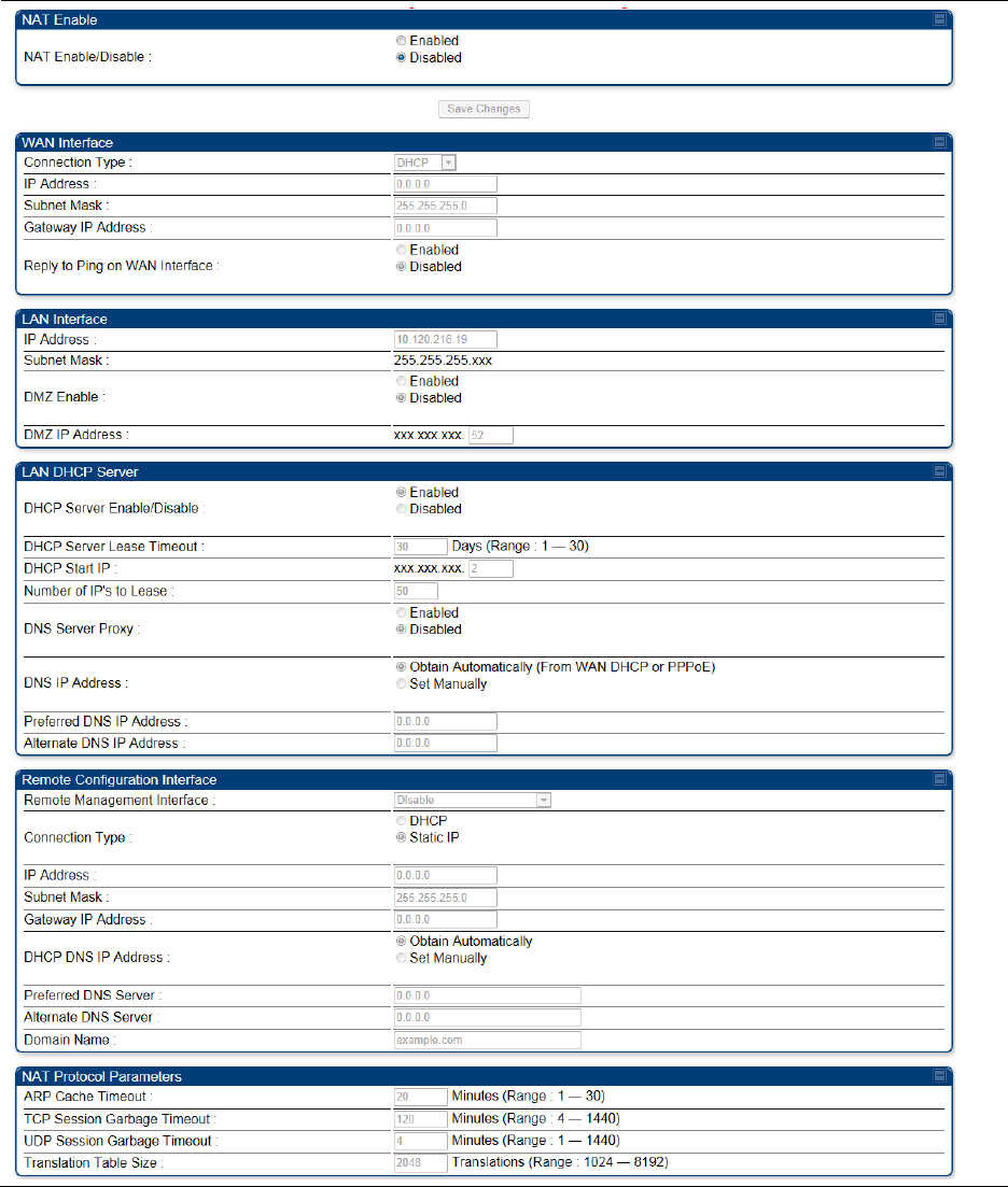
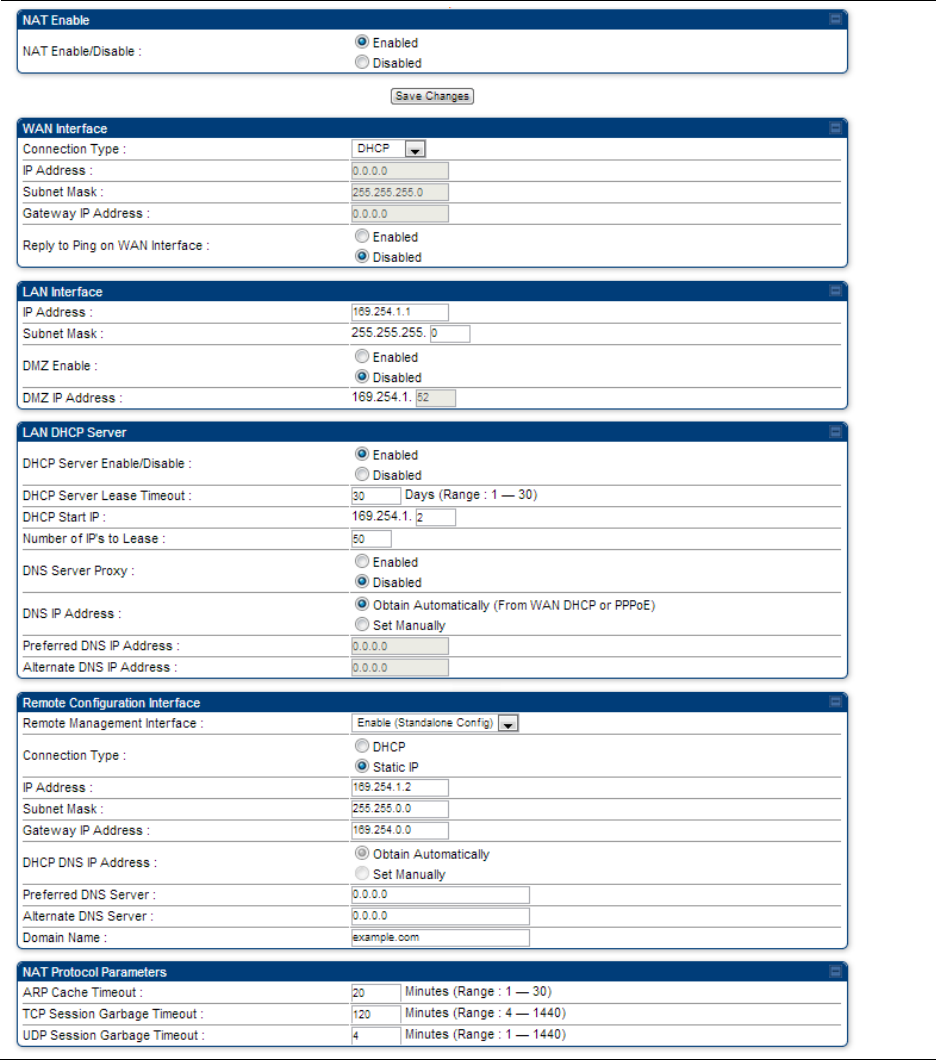
NAT tab with NAT enabled - SM
The NAT tab of SM with NAT enabled is explained in Table 91.
Table 91 NAT attributes - SM with NAT enabled

Chapter 7: Configuration
Configuring IP and Ethernet interfaces
Page 7-109
Attribute
Meaning
NAT Enable/Disable
This parameter enables or disabled the Network Address Translation
(NAT) feature for the SM. NAT isolates devices connected to the Ethernet
or wired side of a SM from being seen directly from the wireless side of
the SM. With NAT enabled, the SM has an IP address for transport traffic
separate from its address for management, terminates transport traffic,
and allows you to assign a range of IP addresses to devices that are
connected to the Ethernet or wired side of the SM.
When NAT is enabled, VLANs are not supported on the wired side of
that SM. You can enable NAT in SMs within a sector where VLAN is
enabled in the AP, but this may constrain network design.
WAN Interface
The WAN interface is the RF-side address for transport traffic.
Connection Type
This parameter may be set to
Static IP—when this is the selection, all three parameters (IP Address,
Subnet Mask, and Gateway IP Address) must be properly populated.
DHCP—when this is the selection, the information from the DHCP server
configures the interface.
PPPoE—when this is the selection, the information from the PPPoE
server configures the interface.
Subnet Mask
If Static IP is set as the Connection Type of the WAN interface, then this
parameter configures the subnet mask of the SM for RF transport traffic.
Gateway IP Address
If Static IP is set as the Connection Type of the WAN interface, then this
parameter configures the gateway IP address for the SM for RF transport
traffic.
Reply to Ping on
WAN Interface
By default, the radio interface does not respond to pings. If you use a
management system (such as WM) that will occasionally ping the SM,
set this parameter to Enabled.
LAN Interface
The LAN interface is both the management access through the Ethernet
port and the Ethernet-side address for transport traffic. When NAT is
enabled, this interface is redundantly shown as the NAT Network
Interface Configuration on the IP tab of the Configuration web page in
the SM.
IP Address
Assign an IP address for SM/BHS management through Ethernet access
to the SM. This address becomes the base for the range of DHCP-
assigned addresses.
Subnet Mask
Assign a subnet mask of 255.255.255.0 or a more restrictive subnet
mask. Set only the last byte of this subnet mask. Each of the first three
bytes is permanently set to 255.
DMZ Enable
Either enable or disable DMZ for this SM/BHS.

Chapter 7: Configuration
Configuring IP and Ethernet interfaces
Page 7-110
DMZ IP Address
If you enable DMZ in the parameter above, set the last byte of the DMZ
host IP address to use for this SM when DMZ is enabled. Only one such
address is allowed. The first three bytes are identical to those of the NAT
private IP address. Ensure that the device that receives network traffic
behind this SM is assigned this address. The system provides a warning
if you enter an address within the range that DHCP can assign.
DHCP Server
This is the server (in the SM) that provides an IP address to the device
connected to the Ethernet port of the SM.
DHCP Server
Enable/Disable
Select either Enabled or Disabled.
Enable to:
Allow this SM to assign IP addresses, subnet masks, and gateway IP
addresses to attached devices.
Assign a start address for DHCP.
Designate how many IP addresses may be temporarily used (leased).
Disable to:
Restrict SM/BHS from assigning addresses to attached devices.
DHCP Server Lease
Timeout
Based on network performance, enter the number of days between
when the DHCP server assigns an IP address and when that address
expires. The range of values for this parameter is 1 to 30 days. The
default value is 30 days.
DHCP Start IP
If you enable DHCP Server below, set the last byte of the starting IP
address that the DHCP server assigns. The first three bytes are identical
to those of the NAT private IP address.
Number of IPs to
Lease
Enter how many IP addresses the DHCP server is allowed to assign. The
default value is 50 addresses.
DNS Server Proxy
This parameter enables or disables advertisement of the SM/BHS as the
DNS server. On initial boot up of a SM with the NAT WAN interface
configured as DHCP or PPPoE, the SM module will not have DNS
information immediately. With DNS Server Proxy disabled, the clients
will renew their lease about every minute until the SM has the DNS
information to give out. At this point the SM will go to the full configured
lease time period which is 30 days by default. With DNS Server Proxy
enabled, the SM will give out full term leases with its NAT LAN IP as the
DNS server.
DNS IP Address
Select either:
Obtain Automatically to allow the system to set the IP address of the
DNS server
or
Set Manually to enable yourself to set both a preferred and an alternate
DNS IP address.
Preferred DNS IP
Address
Enter the preferred DNS IP address to use when the DNS IP Address
parameter is set to Set Manually.
Chapter 7: Configuration
Configuring IP and Ethernet interfaces
Page 7-111
Alternate DNS IP
Address
Enter the DNS IP address to use when the DNS IP Address parameter is
set to Set Manually and no response is received from the preferred DNS
IP address.
Remote
Management
Interface
To offer greater flexibility in IP address management, the NAT-enabled
SM’s configured WAN Interface IP address may now be used as the
device Remote Management Interface (unless the SM’s PPPoE client is
set to Enabled)
Disable: When this interface is set to “Disable”, the SM is not directly
accessible by IP address. Management access is only possible through
either the LAN (Ethernet) interface or a link from an AP web page into
the WAN (RF-side) interface.
Enable (Standalone Config): When this interface is set to “Enable
(Standalone Config)”, to manage the SM/BHS the device must be
accessed by the IP addressing information provided in the Remote
Configuration Interface section.
Note
When configuring PPPoE over the link, use this configuration
option (PPPoE traffic is routed via the IP addressing specified
in section Remote Configuration Interface).
Enable (Use WAN Interface): When this interface is set to “Enable (Use
WAN Interface)”, the Remote Configuration Interface information is
greyed out, and the SM is managed via the IP addressing specified in
section WAN Interface).
Note
When using this configuration, the ports defined in section
Configuration, Port Configuration are consumed by the
device. For example, if FTP Port is configured as 21 by the
SM, an FTP server situated below the SM must use a port
other than 21. This also applies to DMZ devices; any ports
specified in section Configuration, Port Configuration will not
be translated through the NAT, they is consumed by the
device’s network stack for management.
Connection Type
This parameter can be set to:
Static IP—when this is the selection, all three parameters (IP Address,
Subnet Mask, and Gateway IP Address) must be properly populated.
DHCP—when this is the selection, the information from the DHCP server
configures the interface.
IP Address
If Static IP is set as the Connection Type of the WAN interface, then this
parameter configures the IP address of the SM for RF management
traffic.
Subnet Mask
If Static IP is set as the Connection Type of the WAN interface, then this
parameter configures the subnet mask of the SM for RF management
traffic.

Chapter 7: Configuration
Configuring IP and Ethernet interfaces
Page 7-112
Gateway IP Address
If Static IP is set as the Connection Type of the WAN interface, then this
parameter configures the gateway IP address for the SM for RF
management traffic.
Note or print the IP settings from this page. Ensure that you can readily
associate these IP settings both with the module and with the other data
that you store about the module.
DHCP DNS IP
Address
Select either:
Obtain Automatically to allow the system to set the IP address of the
DNS server.
or
Set Manually to enable yourself to set both a preferred and an alternate
DNS IP address.
Preferred DNS
Server
Enter the preferred DNS IP address to use when the DNS IP Address
parameter is set to Set Manually.
Alternate DNS
Server
Enter the DNS IP address to use when the DNS IP Address parameter is
set to Set Manually and no response is received from the preferred DNS
IP address.
Domain Name
Domain Name to use for management DNS configuration. This domain
name may be concatenated to DNS names used configured for the
remote configuration interface.
ARP Cache Timeout
If a router upstream has an ARP cache of longer duration (as some use
30 minutes), enter a value of longer duration than the router ARP cache.
The default value of this field is 20 (minutes).
TCP Session
Garbage Timeout
Where a large network exists behind the SM, you can set this parameter
to lower than the default value of 120 (minutes). This action makes
additional resources available for greater traffic than the default value
accommodates.
UDP Session
Garbage Timeout
You may adjust this parameter in the range of 1 to 1440 minutes, based
on network performance. The default value of this parameter is 4
(minutes).
Chapter 7: Configuration
Configuring IP and Ethernet interfaces
Page 7-113
NAT DNS Considerations - SM
SM DNS behavior is different depending on the accessibility of the SM. When NAT is enabled the
DNS configuration that is discussed in this document is tied to the RF Remote Configuration
Interface, which must be enabled to utilize DNS Client functionality. Note that the WAN DNS
settings when NAT is enabled are unchanged with the addition of the management DNS feature
discussed in this document.
Table 92 SM DNS Options with NAT Enabled
NAT
Configuration
Management Interface
Accessibility
DHCP Status
DNS Status
NAT Enabled
RF Remote
Management Interface
Disabled
N/A
DNS Disabled
RF Remote
Management Interface
Enabled
DHCP Disabled
DNS Static Configuration
DHCP Enabled
DNS from DHCP or DNS
Static Configuration
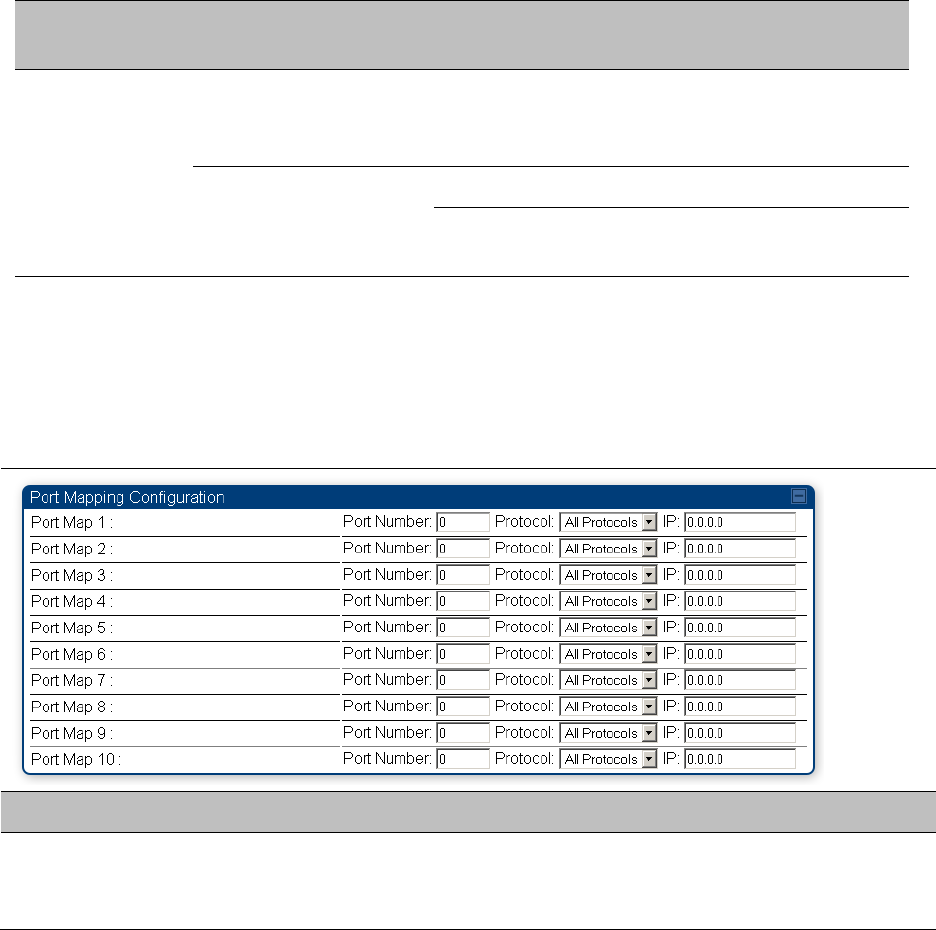
NAT Port Mapping tab - SM
The NAT Port Mapping tab of the SM is explained in Table 93.
Table 93 NAT Port Mapping attributes - SM
Attribute
Meaning
Port Map 1 to 10
Separate parameters allow you to distinguish NAT ports from each other
by assigning a unique combination of port number, protocol for traffic
through the port, and IP address for access to the port

Chapter 7: Configuration
Configuring IP and Ethernet interfaces
Page 7-114
DHCP – BHS
Applicable products
PTP:
BHM
DHCP enables a device to be assigned a new IP address and TCP/IP parameters, including a default
gateway, whenever the device reboots. Thus DHCP reduces configuration time, conserves IP
addresses, and allows modules to be moved to a different network within the Cambium system.
In conjunction with the NAT features, each BHS provides:
A DHCP server that assigns IP addresses to computers connected to the BHS by Ethernet
protocol.
A DHCP client that receives an IP address for the BHS from a network DHCP server.
Reconnecting to the management PC
If the IP Address, Subnet Mask and Gateway IP Address of the unit have been updated to meet
network requirements, then reconfigure the local management PC to use an IP address that is valid
for the network. See Configuring the management PC on page 7-73.
Once the unit reboots, log in using the new IP address. See Logging into the web interface on page
7-75.
VLAN configuration for PMP
Applicable products
PMP :
AP
SM
VLAN Remarking
VLAN Remarking feature allows the user to change the VLAN ID and priority of both upstream
and downstream packets at the Ethernet Interface. The remarking configuration is available for:
1. VLAN ID re-marking
2. 802.1p priority re-marking
Note
For Q-in-Q VLAN tagged frame, re-marking is performed on the outer tag.

Chapter 7: Configuration
Configuring IP and Ethernet interfaces
Page 7-115
VLAN ID Remarking
SM supports the ability to re-mark the VLAN ID on both upstream and downstream VLAN frames
at the Ethernet interface. For instance, a configuration can be added to re-mark VLAN ID ‘x’ to
VLAN ID ‘y’ as shown in Table 94. AP does not support VLAN ID remarking.
Table 94 VLAN Remarking Example
VLAN frame direction
Remarking
Upstream
SM receives VLAN ID ‘x’ frame at the Ethernet interface, checks the
configuration and re-marks to VLAN ID ‘y’. So VLAN ID ‘y’ frame
comes out of AP’s Ethernet interface. When SM re-marks, a
dynamic entry in VLAN membership table for ‘y’ is added to allow
reception of VLAN ID ‘y’ downstream packet.
Downstream
AP receives VLAN ID ‘y’ frame at the Ethernet interface and sends to
SM. SM accepts the frame as it has an entry in the membership
table and re-marks to VLAN ID ‘x’. This reverse re- marking is
necessary because the downstream devices do not know of re-
marking and are expecting VLAN ‘x’ frames. This remarking is done
just before sending the packet out on Ethernet interface.
802.1P Remarking
AP/BHM and SM/BHS allow re-marking of 802.1p priority bits for the frames received at the
Ethernet interface. Priority bits are not re-marked for the packets sent out of Ethernet interface
(reverse direction).
Configuration must be added at SM/BHS for upstream frames and at AP/BHM for downstream
frames.
VLAN Priority Bits configuration
VLAN Priority Bits Configuration feature allows the user to configure the three 802.1p bits upon
assigning VLAN to an ingress packet. The priority bits configuration is available for:
Default Port VID
Provider VID
MAC Address mapped Port VID
Management VID
Default Port VID
This VID is used for untagged frames and will correspond to the Q-Tag for 802.1Q frames (if
VLAN
Port Type is Q), or the C-Tag for 802.1ad frames (if the VLAN Port Type is QinQ).
The priority bits used in the Q-tag/C-tag are configurable.
The configuration can be:
Chapter 7: Configuration
Configuring IP and Ethernet interfaces
Page 7-116
Promote IPv4/IPv6 priority – The priority in the IP header is copied to the Q-tag/C-tag.
Define priority – Specify the priority in the range of 0 to 7. This value is used as priority in the
Q-tag/C-tag.
MAC Address Mapped VID
If a packet arrives at the SM/BHS that is sourced from a device whose MAC address is in the
table, then the corresponding VID is used for that frame’s Q-tag (Q port) or C-tag (QinQ port).
The priority bits used in the Q-tag/C-tag are configurable similar to default port VID.
Provider VID
The provider VID is used for the S-tag. The priority bits used in the S-tag are configurable
similar to default port VID. Provider VID has an extra priority configuration:
Copy inner tag 802.1p priority – The priority in the C-tag is copied to the S-tag.
Management VID
This VID is used to communicate with AP/BHM and SM/BHS for management purposes. The
priority bits used in the Q-tag are configurable similar to default port VID.
Use AP’s Management VID for ICC connected SM
This feature allows the SM to use the AP’s management VLAN ID when the SM is registered to
the AP via ICC. This feature is useful for the customer who uses a different management VID for
the SM and AP and Zero Touch feature is enabled for configuration. This parameter may be
accessed via the Configuration > VLAN page on the AP’s web management interface.
Chapter 7: Configuration
Configuring IP and Ethernet interfaces
Page 7-117
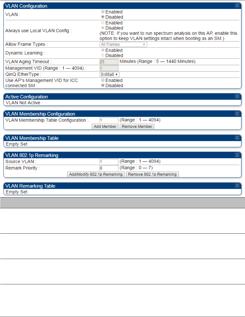
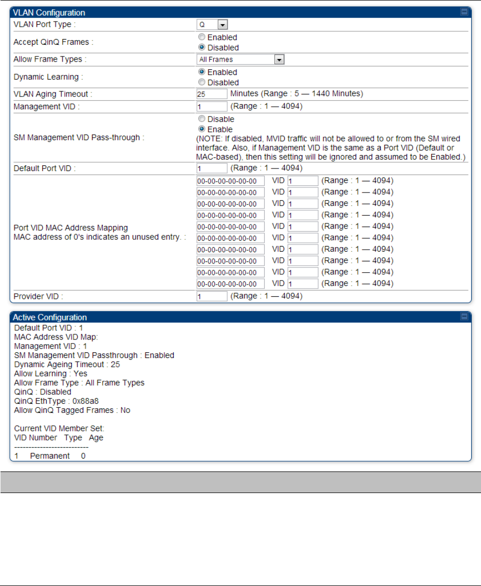
VLAN page of AP
The VLAN tab of the AP/BHM is explained in Table 95.
Table 95 AP/BHM VLAN tab attributes
Attribute
Meaning
VLAN
Specify whether VLAN functionality for the AP and all linked SMs must
(Enabled) or may not (Disabled) be allowed. The default value is
Disabled.
Always use Local
VLAN Config
Enable this option before you reboot this AP as a SM to use it to perform
spectrum analysis. Once the spectrum analysis completes, disable this
option before you reboot the module as an AP,
Allow Frame Types
Select the type of arriving frames that the AP must tag, using the VID
that is stored in the Untagged Ingress VID parameter. The default value
is All Frames.
Dynamic Learning
Specify whether the AP must (Enabled) or not (Disabled) add the VLAN
IDs (VIDs) of upstream frames to the VID table. (The AP passes frames
with VIDs that are stored in the table both upstream and downstream.).
The default value is Enabled.

Chapter 7: Configuration
Configuring IP and Ethernet interfaces
Page 7-118
VLAN Aging Timeout
Specify how long the AP must keep dynamically learned VIDs. The range
of values is 5 to 1440 (minutes). The default value is 25 (minutes).
Note
VIDs that you enter for the Management VID and VLAN
Membership parameters do not time out.
Management VID
Enter the VID that the operator wishes to use to communicate with the
module manager. The range of values is 1 to 4095. The default value is 1.
QinQ EtherType
Modules can be configured with 802.1ad Q-in-Q DVLAN (Double-VLAN)
tagging which is a way for an operator to put an 802.1Q VLAN inside of
an 802.1ad VLAN. A nested VLAN, which is the original 802.1Q tag and a
new second 802.1ad tag, allows for bridging of VLAN traffic across a
network and segregates the broadcast domains of 802.1Q VLANs. Q-in-Q
can be used with PPPoE and/or NAT.
The 802.1ad standard defines the S-VLAN as the Service Provider VLAN
and the C-VLAN as the customer VLAN. The radio software does 2 layer
Q-in-Q whereby the C-VLAN is the 802.1Q tag and the S-VLAN is the
second layer Q tag as shown below:
Table 96 Q-in-Q Ethernet frame
Ethernet
Header
S-VLAN
EthType 0x88a8
C-VLAN EthType
0x8100
IP Data EthType
0x0800
The 802.1ad S-VLAN is the outer VLAN that is configurable on the
Configuration > VLAN web page of the AP. The Q-in-Q EtherType
parameter is configured with a default EtherType of 0x88a8 in addition
to four alternate EtherTypes that can be configured to aid in
interoperability with existing networks that use a different EtherType
than the default.
The C-VLAN is the inner VLAN tag, which is the same as 802.1Q. As a top
level concept, this operates on the outermost tag at any given time,
either “pushing” a tag on or “popping” a tag off. This means packets
will at most transition from an 802.1Q frame to an 801.ad frame (with a
tag “pushed” on) or an untagged 802.1 frame (with the tag “popped”
off. Similarly, for an 802.1ad frame, this can only transition from an
802.1ad frame to an 802.1Q frame (with the tag “popped” off) since the
radio software only supports 2 levels of tags
Use AP's
Management VID for
ICC connected SM
This field allows the SM to use the AP’s management VLAN ID when the
SM is registered to the AP via ICC.

Chapter 7: Configuration
Configuring IP and Ethernet interfaces
Page 7-119
VLAN Not Active
When VLAN is enabled in the AP, the Active Configuration block
provides the following details as read-only information in this tab. In the
Cambium fixed wireless broadband IP network, each device of any type
is automatically a permanent member of VID 1. This facilitates
deployment of devices that have VLAN enabled with those that do not.
VLAN Membership
Table Configuration
For each VLAN in which you want the AP to be a member, enter the
VLAN ID and then click the Add Member button. Similarly, for any VLAN
in which you want the AP to no longer be a member, enter the VLAN ID
and then click the Remove Member button.
VLAN Membership
table
This field lists the VLANs that an AP is a member of. As the user adds a
number between 1 and 4094, this number is populated here.
Source VLAN
(Range: 1-4094)
Enter the VID for which the operator wishes to remark the 802.1p priority
for the downstream packets. The range of values is 1 to 4094. The
default value is 1.
Remark Priority
(Range 0-7)
This is the priority you can assign to the VLAN Tagged packet. Priority of
0 is the highest.
VLAN Remarking
table
As the user enters a VLAN and a Remarking priority, this information is
added in this table.
Chapter 7: Configuration
Configuring IP and Ethernet interfaces
Page 7-120
VLAN page of SM
The VLAN tab of SM/BHS is explained in Table 97.
Table 97 SM VLAN attributes
Attribute
Meaning
VLAN Port Type
By default this is Q, indicating that it is to operate in the existing manner.
The other option is Q-in-Q, which indicates that it must be adding and
removing the S-Tag, and adding a C-Tag if necessary for untagged
packets. The VLAN Port type corresponds to the Ethernet port of the
SM/BHS. Currently, the internal management interfaces will always
operate as Q ports.
Chapter 7: Configuration
Configuring IP and Ethernet interfaces
Page 7-121
Accept QinQ Frames
This option is valid for the Q-in-Q port so that the user may force
blocking of existing 802.1ad Q-in-Q frames. This way, only untagged or
single tagged packets will come in and out of the Ethernet interface. If a
Q-in-Q frame is about ingress or egress the Ethernet interface and this is
disabled, it is dropped and a filter entry will show up on the VLAN
Statistics page as DVLAN Egress or DVLAN Ingress.
Allow Frame Types
Select the type of arriving frames that the SM must tag, using the VID
that is stored in the Untagged Ingress VID parameter. The default value
is All Frames.
Tagged Frames Only: The SM only tags incoming VLAN-tagged frames
Untagged Frames Only: The SM will only tag incoming untagged frames
Dynamic Learning
Specify whether the SM must (Enable) or not (Disable) add the VIDs of
upstream frames (that enter the SM through the wired Ethernet
interface) to the VID table. The default value is Enable.
VLAN Aging Timeout
Specify how long the SM/BHS must keep dynamically learned VIDs. The
range of values is 5 to 1440 (minutes). The default value is 25 (minutes).
Note
VIDs that you enter for the Untagged Ingress VID and
Management VID parameters do not time out.
Management VID
Enter the VID that the SM/BHS must share with the AP/BHM. The range
of values is 1 to 4095. The default value is 1.
SM Management
VID Pass-through
Specify whether to allow the SM/BHS (Enabled) or the AP/RADIUS
(Disabled) to control the VLAN settings of this SM. The default value is
Enabled.
When VLAN is enabled in the AP to whom this SM is registered, the
Active Configuration block provides the following details as read-only
information in this tab. In the Cambium fixed wireless broadband IP
network, each device of any type is automatically a permanent member
of VID 1. This facilitates deployment of devices that have VLAN enabled
with those that do not.
If disabled, MVID traffic is not allowed to or from the SM wired interface.
Also, if Management VID is the same as a Port VID (Default or MAC-
based), then this setting is ignored and assumed to be Enabled.
Default Port VID
This is the VID that is used for untagged frames and will correspond to
the Q-Tag for 802.1Q frames (if VLAN Port Type is Q), or the C-Tag for
802.1ad frames (if the VLAN Port Type is Q-in- Q).

Chapter 7: Configuration
Configuring IP and Ethernet interfaces
Page 7-122
Port VID MAC
Address Mapping
These parameters allow operators to place specific devices onto
different VLANs (802.1Q tag or 802.1ad C-tag) based on the source
MAC address of the packet. If the MAC address entry is 00-00-00-00-00-
00 then that entry is not used. If a packet arrives at the SM that is
sourced from a device whose MAC address is in the table, then the
corresponding VID is used for that frame’s Q-tag (Q port) or C-tag (Q-
in-Q port). If there is no match, then the Default Port VID is used. This
table is also used in the downstream direction for removal of the tag
based on the destination MAC address so that an untagged (for Q port)
or Q-Tagged (for Q-in-Q port) frame is delivered to the end device. You
may use wildcards for the non-OUI (Organizationally Unique Identifier)
portion of the MAC address, which is the last 3 bytes. MAC addresses
contain 6 bytes, the first 3 of which are the OUI of the vendor that
manufactured the device and the last 3 are unique to that vendor OUI.
If you want to cover all devices from a known vendor’s OUI, you have
to specify 0xFF for the remaining 3 bytes. So, for example, if you
wanted all devices from a specific vendor with an OUI of 00-95-5b
(which is a Netgear OUI) to be on the same VID of 800, you have to
specify an entry with MAC address 00-95-5b-ff-ff-ff. Then, any device
underneath of the SM with MAC addresses starting with 00-95-5b is put
on VLAN 800.
Provider VID
The provider VID is used for the S-tag. It is only used if the Port Type is
Q-in-Q and will always be used for the S-tag. If an existing 802.1Q
frame arrives, the Provider VID is what is used for adding and
removing of the outer S-tag. If an untagged frame arrives to a Q-in-Q
port, then the Provider VID is the S-tag and the Default Port VID (or Port
VID MAC Address Mapping, if valid) is used for the C-tag.
Active Configuration,
Default Port VID
This is the value of the parameter of the same name, configured above.
Active Configuration,
MAC Address VID
Map
This is the listing of the MAC address VIDs configured in Port VID MAC
Address Mapping.
Active Configuration,
Management VID
This is the value of the parameter of the same name, configured above.
Active Configuration,
SM Management
VID Pass-Through
This is the value of the parameter of the same name, configured above.
Active Configuration,
Dynamic Aging
Timeout
This is the value of the VLAN Aging Timeout parameter configured
above.
Active Configuration,
Allow Learning
Yes is displayed if the value of the Dynamic Learning parameter above is
Enabled. No is displayed if the value of Dynamic Learning is Disabled.

Chapter 7: Configuration
Configuring IP and Ethernet interfaces
Page 7-123
Active Configuration,
Allow Frame Type
This displays the selection that was made from the drop-down list at the
Allow Frame Types parameter above.
Active Configuration,
QinQ
This is set to Enabled if VLAN Port Type is set to QinQ, and is set to
Disabled if VLAN Port Type is set to Q.
Active Configuration,
QinQ EthType
This is the value of the QinQ EtherType configured in the AP.
Active Configuration,
Allow QinQ Tagged
Frames
This is the value of Accept QinQ Frames, configured above.
Active Configuration,
Current VID Member
Set, VID Number
This column lists the ID numbers of the VLANs in which this module is a
member, whether through assignment or through dynamic learning.
Active Configuration,
Current VID Member
Set, Type
For each VID number in the first column, the entry in this column
correlates the way in which the module became and continues to be a
member:
Permanent—This indicates that the module was assigned the VID
number through direct configuration by the operator.
Dynamic—This indicates that the module adopted the VID number
through enabled dynamic learning, when a tagged packet from a SM
behind it in the network or from a customer equipment that is behind the
SM in this case, was read.
Active Configuration,
Current VID Member
Set, Age
For each VID number in the first column of the table, the entry in this
column reflects whether or when the VID number will time out:
Permanent type - Number never times out and this is indicated by the
digit 0.
Dynamic type - Age reflects what is configured in the VLAN Aging
Timeout parameter in the Configuration => VLAN tab of the AP or
reflects a fewer number of minutes that represents the difference
between what was configured and what has elapsed since the VID was
learned. Each minute, the Age decreases by one until, at zero, the AP
deletes the learned VID, but can it again from packets sent by elements
that are beneath it in the network.
Note
Values in this Active Configuration block can differ from
attempted values in configurations:
The AP can override the value that the SM has configured for
SM Management VID Pass-Through.
Chapter 7: Configuration
Configuring IP and Ethernet interfaces
Page 7-124
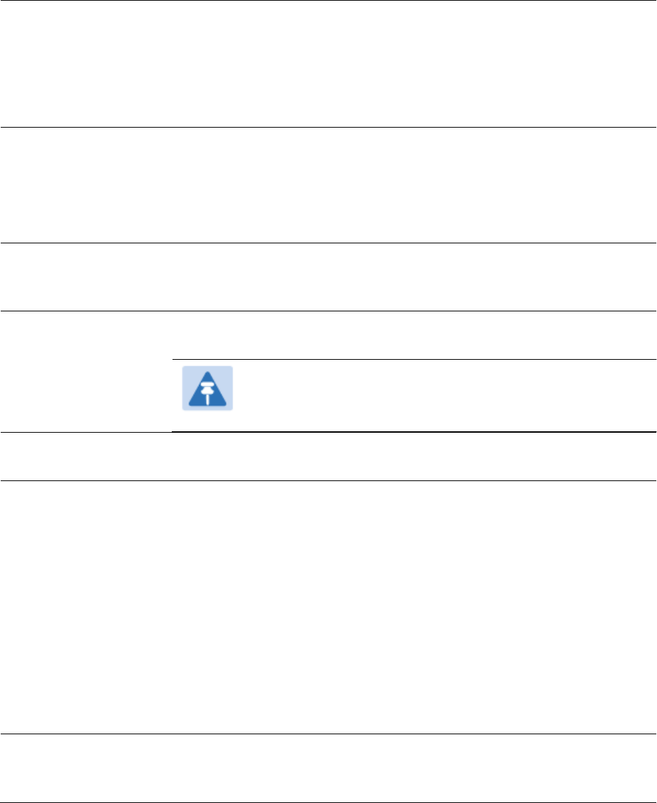
VLAN Membership tab of SM
The Configuration > VLAN > VLAN Membership tab is explained in Table 98.
Table 98 SM VLAN Membership attributes
Attribute
Meaning
VLAN Membership
Table Configuration
For each VLAN in which you want the AP to be a member, enter the
VLAN ID and then click the Add Member button. Similarly, for any VLAN
in which you want the AP to no longer be a member, enter the VLAN ID
and then click the Remove Member button.
VLAN configuration for PTP
Applicable products
PTP:
BHM
BMS
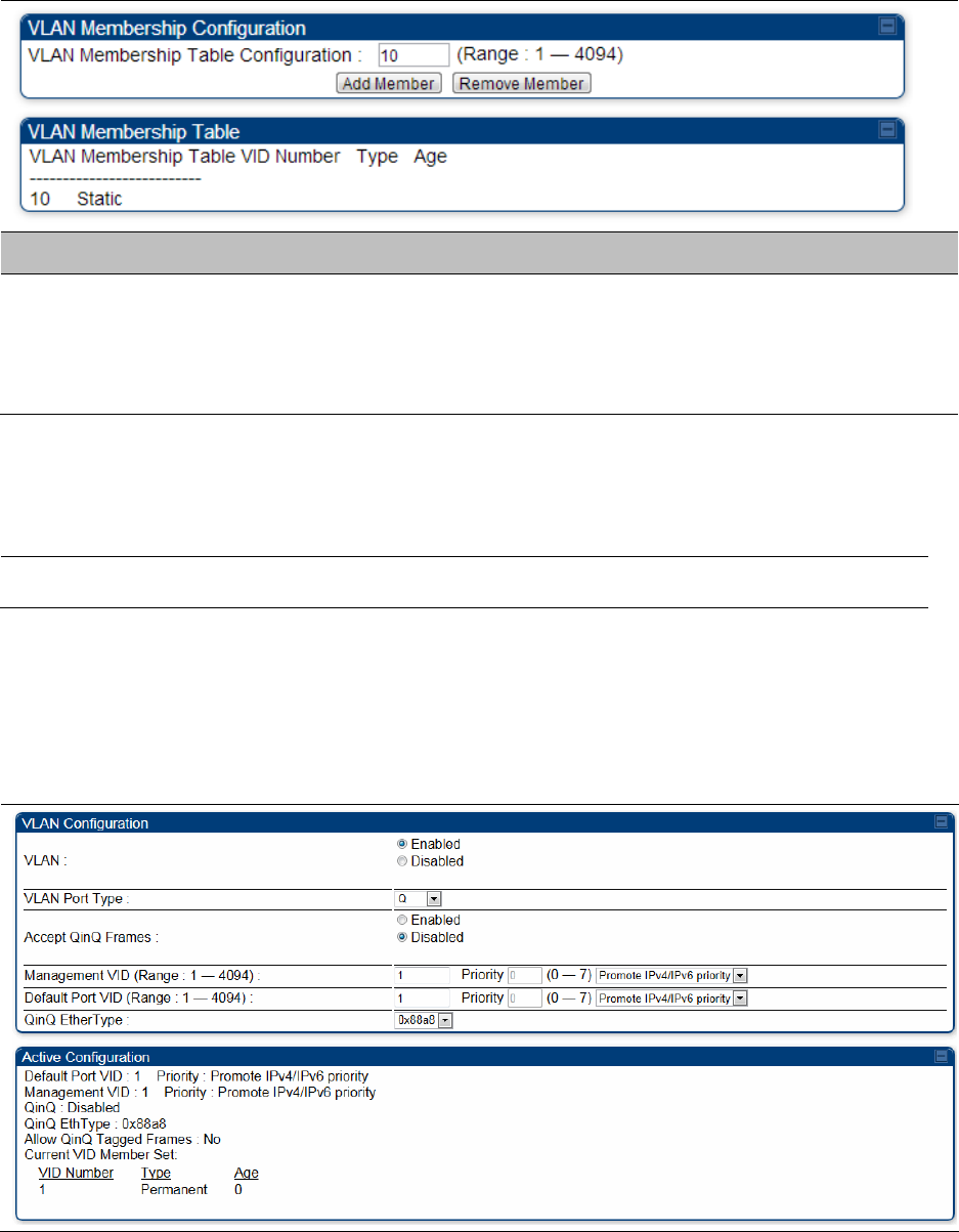
VLAN page of BHM
The VLAN tab of BHS is explained in Table 99.
Table 99 BHM VLAN page attributes

Chapter 7: Configuration
Configuring IP and Ethernet interfaces
Page 7-125
Attribute
Meaning
VLAN
Specify whether VLAN functionality for the BHM and all linked BHS must
be (Enabled) or may not (Disabled) be allowed. The default value is
Disabled.
VLAN Port Type
By default this is Q, indicating that it is to operate in the existing manner.
The other option is Q-in-Q, which indicates that it must be adding and
removing the S-Tag, and adding a C-Tag if necessary for untagged
packets. The VLAN Port type corresponds to the Ethernet port of the
BHS. Currently, the internal management interfaces will always operate
as Q ports.
Accept QinQ Frames
This option is valid for the Q-in-Q port so that the user may force
blocking of existing 802.1ad Q-in-Q frames. This way, only untagged or
single tagged packets will come in and out of the Ethernet interface. If a
Q-in-Q frame is about ingress or egress the Ethernet interface and this is
disabled, it is dropped and a filter entry will show up on the VLAN
Statistics page as DVLAN Egress or DVLAN Ingress.
Management VID
(Range 1-4094)
Enter the VID that the BHS must share with the BHM. The range of
values is 1 to 4095. The default value is 1.
Default Port VID
(Range 1-4094)
This is the VID that is used for untagged frames and corresponds to the
Q-Tag for 802.1Q frames (if VLAN Port Type is Q), or the C-Tag for
802.1ad frames (if the VLAN Port Type is Q-in- Q).
QinQ Ether Type
Modules can be configured with 802.1ad Q-in-Q DVLAN (Double-VLAN)
tagging which is a way for an operator to put an 802.1Q VLAN inside of
an 802.1ad VLAN. A nested VLAN, which is the original 802.1Q tag and a
new second 802.1ad tag, allows for bridging of VLAN traffic across a
network and segregates the broadcast domains of 802.1Q VLANs. Q-in-Q
can be used with PPPoE and/or NAT.
The 802.1ad standard defines the S-VLAN as the Service Provider VLAN
and the C-VLAN as the customer VLAN. The radio software does 2 layer
Q-in-Q whereby the C-VLAN is the 802.1Q tag and the S-VLAN is the
second layer Q tag as shown below:
Ethernet
Header
S-VLAN EthType
0x88a8
C-VLAN
EthType 0x8100
IP Data EthType
0x0800
The 802.1ad S-VLAN is the outer VLAN that is configurable on the
Configuration > VLAN web page of the BHM. The Q-in-Q EtherType
parameter is configured with a default EtherType of 0x88a8 in addition
to four alternate EtherTypes that can be configured to aid in
interoperability with existing networks that use a different EtherType
than the default.

Chapter 7: Configuration
Configuring IP and Ethernet interfaces
Page 7-126
The C-VLAN is the inner VLAN tag, which is the same as 802.1Q. As a top
level concept, this operates on the outermost tag at any given time,
either “pushing” a tag on or “popping” a tag off. This means packets
will at most transition from an 802.1Q frame to an 801.ad frame (with a
tag “pushed” on) or an untagged 802.1 frame (with the tag “popped”
off. Similarly, for an 802.1ad frame, this can only transition from an
802.1ad frame to an 802.1Q frame (with the tag “popped” off) since the
radio software only supports 2 levels of tags.
VLAN Not Active
When VLAN is enabled in the BHM, the Active Configuration block
provides the following details as read-only information in this tab. In the
Cambium fixed wireless broadband IP network, each device of any type
is automatically a permanent member of VID 1. This facilitates
deployment of devices that have VLAN enabled with those that do not.
Chapter 7: Configuration
Configuring IP and Ethernet interfaces
Page 7-127
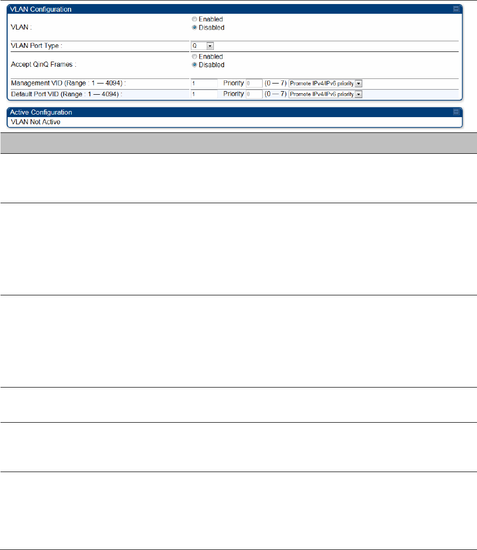
VLAN page of BHS
The VLAN tab of BHS is explained in Table 100.
Table 100 BHS VLAN page attributes
Attribute
Meaning
VLAN
Specify whether VLAN functionality for the BHM and all linked BHS must
be (Enabled) or may not (Disabled) be allowed. The default value is
Disabled.
VLAN Port Type
By default this is Q, indicating that it is to operate in the existing manner.
The other option is Q-in-Q, which indicates that it must be adding and
removing the S-Tag, and adding a C-Tag if necessary for untagged
packets. The VLAN Port type corresponds to the Ethernet port of the
BHS. Currently, the internal management interfaces will always operate
as Q ports.
Accept QinQ Frames
This option is valid for the Q-in-Q port so that the user may force
blocking of existing 802.1ad Q-in-Q frames. This way, only untagged or
single tagged packets will come in and out of the Ethernet interface. If a
Q-in-Q frame is about ingress or egress the Ethernet interface and this is
disabled, it is dropped and a filter entry will show up on the VLAN
Statistics page as DVLAN Egress or DVLAN Ingress.
Management VID
(Range 1-4094)
Enter the VID that the BHS must share with the BHM. The range of
values is 1 to 4095. The default value is 1.
Default Port VID
(Range 1-4094)
This is the VID that is used for untagged frames and corresponds to the
Q-Tag for 802.1Q frames (if VLAN Port Type is Q), or the C-Tag for
802.1ad frames (if the VLAN Port Type is Q-in- Q).
VLAN Not Active
When VLAN is enabled in the BHM, the Active Configuration block
provides the following details as read-only information in this tab. In the
Cambium fixed wireless broadband IP network, each device of any type
is automatically a permanent member of VID 1. This facilitates
deployment of devices that have VLAN enabled with those that do not.

Chapter 7: Configuration
Configuring IP and Ethernet interfaces
Page 7-128
PPPoE page of SM
Applicable products
PMP :
SM
Point-to-Point Protocol over Ethernet (PPPoE) is a protocol that encapsulates PPP frames inside
Ethernet frames (at Ethernet speeds). Benefits to the network operator may include
Access control
Service monitoring
Generation of statistics about activities of the customer
Re-use of infrastructure and operational practices by operators who already use PPP for other
networks
PPPoE options are configurable for the SM only, and the AP indicates whether or not PPPoE is
enabled for a specific subscriber.
When PPPoE is enabled, once the RF session comes up between the SM and the AP, the SM will
immediately attempt to connect to the PPPoE Server. You can monitor the status of this by viewing
the PPPoE Session Log in the Logs section (Administrator only). Every time the RF session comes
up, the SM will check the status of the link and if it is down, the SM will attempt to redial the link if
necessary depending on the Timer Type. Also, on the Configuration page, the user may ‘Connect’
or ‘Disconnect’ the session manually. This can be used to override the session to force a manual
disconnect and/or reconnect if there is a problem with the session.
In order to enable PPPoE, NAT MUST be enabled on the SM and Translation Bridging MUST be
disabled on the AP. These items is strictly enforced for you when you are trying to enable PPPoE.
A message will indicate any prerequisites not being met. Also, the NAT Public IP DHCP client
cannot be enabled, because the NAT Public IP is received through the IPCP process of the PPPoE
discovery stages.
The pre-requisites are:
NAT MUST be enabled on the SM
o NAT DHCP Client is disabled automatically. The NAT public IP is received from the PPPoE
Server.
o NAT Public Network Interface Configuration will not be used and must be left to defaults.
Also NAT Public IP DHCP is disabled if it is enabled.
Translation Bridging MUST be DISABLED on the AP
o This will only be determined if the SM is in session since the SM won’t know the AP
configuration otherwise. If the SM is not in session, PPPoE can be enabled but if the SM
goes into session to a Translation Bridge-enabled AP, then PPPoE will not be enabled.
The PPPoE configuration parameters are explained in Table 101.
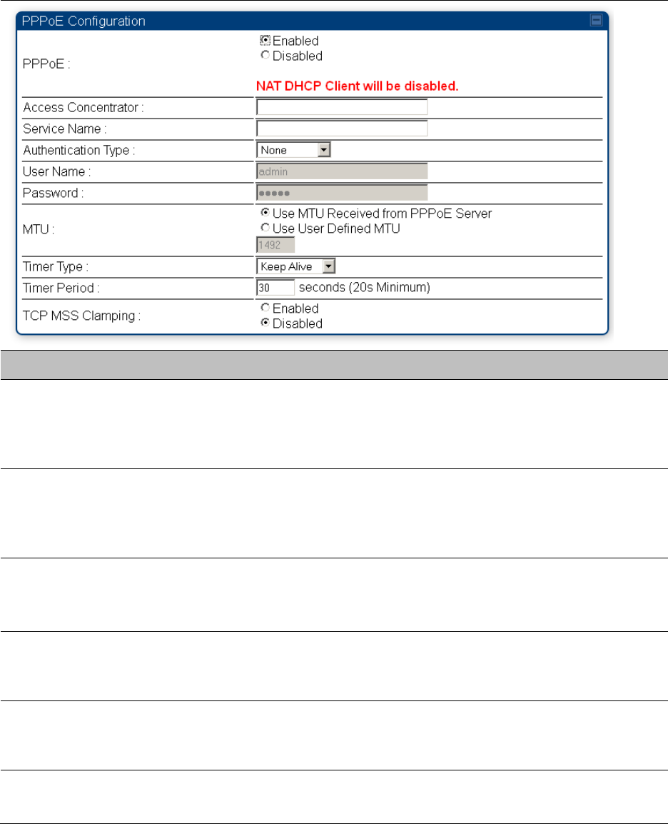
Chapter 7: Configuration
Configuring IP and Ethernet interfaces
Page 7-129
Table 101 SM PPPoE attributes
Attribute
Meaning
Access Concentrator
An optional entry to set a specific access concentrator to connect to for
the PPPoE session. If this is blank, the SM will accept the first access
concentrator which matches the service name (if specified). This is
limited to 32 characters.
Service Name
An optional entry to set a specific service name to connect to for the
PPPoE session. If this is left blank the SM will accept the first service
option that comes back from the access concentrator specified above, if
any. This is limited to 32 characters.
Authentication Type
None means that no PPPoE authentication is implemented
CHAP/PAP means that CHAP authentication is attempted first, then PAP
authentication. The same password is used for both types.
User Name
This is the CHAP/PAP user name that is used if CHAP/PAP authentication
is selected. If None is selected for authentication then this field is
unused. This is limited to 32 characters.
Password
This is the CHAP/PAP password that is used if PAP authentication is
selected. If None is selected for authentication then this field is unused.
This is limited to 32 characters.
MTU
Use MTU Received from PPPoE Server causes the SM to use the MRU of
the PPPoE server received in LCP as the MTU for the PPPoE link.

Chapter 7: Configuration
Configuring IP and Ethernet interfaces
Page 7-130
Use User Defined MTU allows the operator to specify an MTU value to
use to override any MTU that may be determined in the LCP phase of
PPPoE session setup. If this is selected, the user is able to enter an MTU
value up to 1492. However, if the MTU determined in LCP negotiations is
less than this user-specified value, the SM will use the smaller value as
its MTU for the PPPoE link.
Timer Type
Keep Alive is the default timer type. This timer will enable a keepalive
that will check the status of the link periodically. The user can set a
keepalive period. If no data is seen from the PPPoE server for that
period, the link is taken down and a reconnection attempt is started. For
marginal links, the keep alive timer can be useful so that the session will
stay alive over periodic dropouts. The keepalive timer must be set such
that the session can outlast any session drop. Some PPPoE servers will
have a session check timer of their own so that the timeouts of the
server and the SM are in sync, to ensure one side does not drop the
session prematurely.
Idle Timeout enables an idle timer that checks the usage of the link from
the customer side. If there is no data seen from the customer for the idle
timeout period, the PPPoE session is dropped. Once data starts flowing
from the customer again, the session is started up again. This timer is
useful for users who may not be using the connection frequently. If the
session is idle for long periods of time, this timer will allow the
resources used by the session to be returned to the server. Once the
connection is used again by the customer, the link is reestablished
automatically.
Timer Period
The length in seconds of the PPPoE keepalive timer.
TCP MSS Clamping
If this is enabled, then the SM will alter TCP SYN and SYN-ACK packets
by changing the Maximum Segment Size to be compatible with the
current MTU of the PPPoE link. This way, the user does not have to
worry about MTU on the client side for TCP packets. The MSS is set to
the current MTU – 40 (20 bytes for IP headers and 20 bytes for TCP
headers). This will cause the application on the client side to not send
any TCP packets larger than the MTU. If the network is exhibiting large
packet loss, try enabling this option. This may not be an option on the
PPPoE server itself. The SM will NOT reassemble IP fragments, so if the
MTUs are incorrect on the end stations, then MSS clamping will solve
the problem for TCP connections.
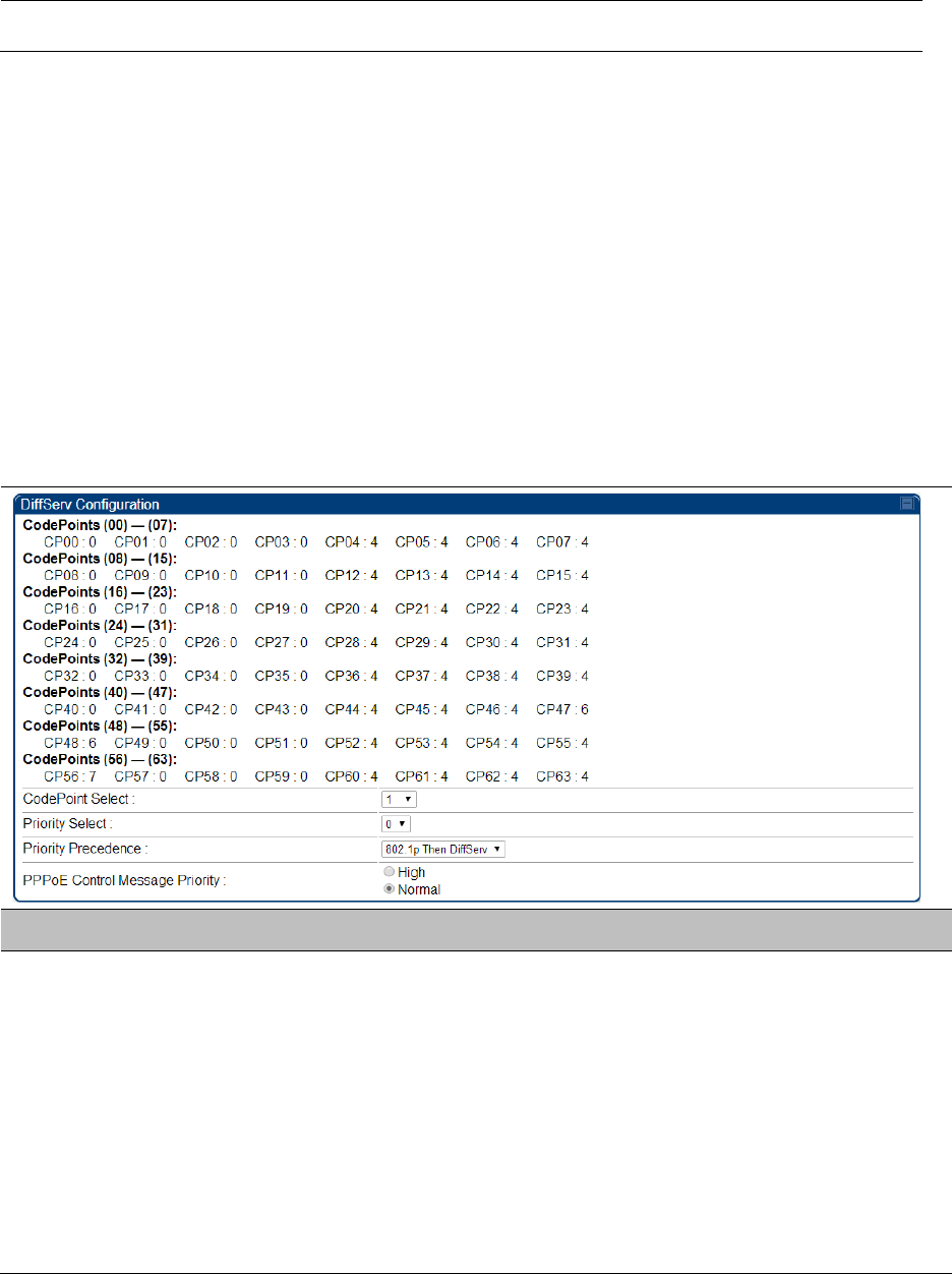
Chapter 7: Configuration
Configuring IP and Ethernet interfaces
Page 7-131
IP4 and IPv6
Applicable products
PMP :
AP
SM
PTP:
BHM
BMS
IPv4 and IPv6 Prioritization
PMP/PTP 450 platform provides operators the ability to prioritize IPv6 traffic in addition to IPv4
traffic. IPv6/IPv4 prioritization can be configured by selecting a CodePoint and the
corresponding priority from the GUI of the AP/BHM and the IPv6/IPv4 packet is set up
accordingly. There is no GUI option for selecting IPv6 or IPv4 priority. Once the priority is set, it
is set for IPv4 and IPv6 packets.
Configuring IPv4 and IPv6 Priority
IPv4 and IPv6 prioritization is set using the DiffServ tab on the AP/BHM and SM/BHS (located at
Configuration > DiffServ). A priority set to a specific CodePoint will apply to both IPv4 and IPv6
traffic.
Table 102 DiffServ attributes – AP/BHM
Attribute
Meaning
CodePoint 1 through
CodePoint 47
CodePoint 49
through CodePoint
55
CodePoint 57
through CodePoint
63
Priorities of 0 through 3 map to the low-priority channel; 4 through 7 to
the high- priority channel. The mappings are the same as 802.1p VLAN
priorities.
Consistent with RFC 2474
CodePoint 0 is predefined to a fixed priority value of 0 (low-priority
channel).
CodePoint 48 is predefined to a fixed priority value of 6 (high-priority
channel). CodePoint 56 is predefined to a fixed priority value of 7 (high-
priority channel).

Chapter 7: Configuration
Configuring IP and Ethernet interfaces
Page 7-132
Operator cannot change any of these three fixed priority values. Among
the settable parameters, the priority values (and therefore the handling
of packets in the high or low priority channel) are set in the AP/BHM for
all downlinks within the sector and in the SM/BHS for each uplink.
CodePoint Select
This represents the CodePoint Selection to be modified via Priority
Select
Priority Select
The priority setting input for the CodePoint selected in CodePoint Select
Priority Precedence
Allows operator to decide if 802.1p or DiffServ priority bits must be used
first when making priority decisions.
PPPoE Control
Message Priority
Operators may configure the AP/BHM to utilize the high priority channel
for PPPoE control messages. Configuring the AP/BHM in this fashion can
benefit the continuity of PPPoE connections when there are issues with
PPPoE sessions being dropped in the network. This prioritization may be
configured in the DiffServ tab in the Configuration menu of the AP/BHM.
IPv4 and IPv6 Filtering
The operator can filter (block) specified IPv6 protocols including IPv4 and ports from leaving the
AP/BHM and SM/BHS and entering the network. This protects the network from both intended and
inadvertent packet loading or probing by network users. By keeping the specified protocols or
ports off the network, this feature also provides a level of protection to users from each other.
Configuring IPv4 and IPv6 Filtering
IPv6 filters are set using the Protocol Filtering tab on the AP/BHM and SM/BHS (at Configuration >
Protocol Filtering). Once a filter is set for a packet type, those packets will not be sent over the RF
interface depending on “Filter Direction” setting.
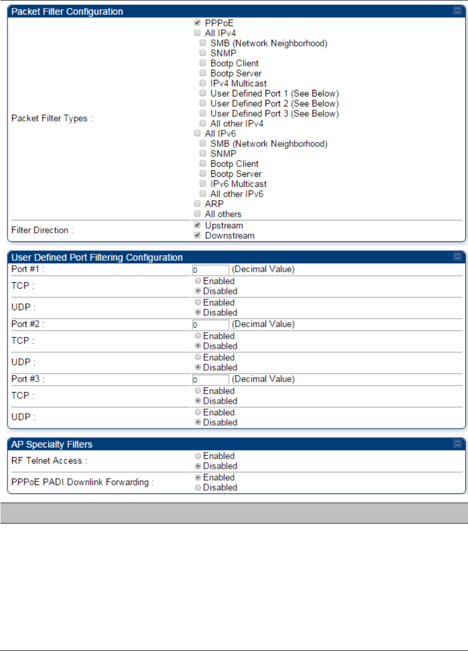
Chapter 7: Configuration
Configuring IP and Ethernet interfaces
Page 7-133
Table 103 Packet Filter Configuration attributes
Attribute
Meaning
Packet Filter Types
For any box selected, the Protocol and Port Filtering feature blocks the
associated protocol type.
To filter packets in any of the user-defined ports, you must do all of the
following:
Check the box for User Defined Port n (See Below) in the Packet
Filter Types section of this tab.
Provide a port number at Port #n. in the User Defined Port Filtering
Configuration section of this tab

Chapter 7: Configuration
Configuring IP and Ethernet interfaces
Page 7-134
Enable TCP and/or UDP by clicking the associated radio button
Filter Direction
Operators may choose to filter upstream (uplink) RF packets or
downstream (downlink) RF packets.
User Defined Port
Filtering
Configuration
You can specify ports for which to block subscriber access, regardless of
whether NAT is enabled.
Chapter 7: Configuration
Upgrading the software version and using CNUT
Page 7-135
Upgrading the software version and using CNUT
This section consists of the following procedures:
Checking the installed software version on page 7-135
Upgrading to a new software version on page 7-135
Caution
If the link is operational, ensure that the remote end of the link is upgraded first using
the wireless connection, and then the local end can be upgraded. Otherwise, the
remote end may not be accessible.
Use CNUT 4.9.12 or later version and always refer to the software release notes before
upgrading system software. The release notes are available at:
https://support.cambiumnetworks.com/files/pmp450
https://support.cambiumnetworks.com/files/ptp450
Checking the installed software version
To check the installed software version, follow these instructions:
Procedure 18 Checking the installed software version
1
Click on General tab under Home menu.
2
Note the installed Software Version (under Device Information):
PMP/PTP 450/450i
3
Go to the support website (see Contacting Cambium Networks on page 1) and find
Point-to-Multipoint software updates. Check that the latest PMP/PTP 450 platform
software version is the same as the installed Software Version.
4
To upgrade software to the latest version, see Upgrading to a new software version on
page 7-135.
Upgrading to a new software version
PMP/PTP 450i modules are upgraded using the Canopy Network Updater Tool. The Canopy
Network Updater Tool (CNUT) manages and automates the software and firmware upgrade
process for a Canopy radio, or CMM4 (but not its 14-port switch) across the network. This
eliminates the need for an administrator to visit each radio in the network (or each AP/BHM while
using the Autoupdate feature) to upgrade the modules.

Chapter 7: Configuration
Upgrading the software version and using CNUT
Page 7-136
Note
Please ensure that you have the most up-to-date version of CNUT by browsing to the
Customer Support Web Page located:
http://www.cambiumnetworks.com/support/management-tools/cnut
This section includes an example of updating a single unit before deployment. System-wide
upgrading procedures may be found in the CNUT Online Help manual, which can be found on the
Cambium support website (see Contacting Cambium Networks on page 1).
CNUT functions
The Canopy Network Updater tool has the following functions:
Automatically discovers all network elements
Executes a UDP command that initiates and terminates the Auto-update mode within
APs/BHMs. This command is both secure and convenient:
o For security, the AP/BHM accepts this command from only the IP address that you specify
in the Configuration page of the AP/BHM.
o For convenience, Network Updater automatically sets this Configuration parameter in the
APs/BHMs to the IP address of the Network Updater server when the server performs any
of the update commands.
CNUT supports HTTP and HTTPS
Allows you to choose the following among updating:
o Your entire network.
o Only elements that you select.
o Only network branches that you select.
Provides a Script Engine that you can use with any script that:
o You define.
o Cambium supplies.
Configurability of any of the following to be the file server for image files:
o The AP/BHM, for traditional file serving via UDP commands and monitoring vai UDP
messaging
o CNUT HTTP/HTTPS Server, for upgrading via SNMP commands and monitoring via SNMP
messaging. This also supports an option to either set the image order specifically for this
file server or to allow the AP to determine the order.
o Local TFTP Server, for traditional file serving via UDP commands and monitoring via UDP
messaging. This supports setting the number of simultaneous image transfers per AP/BHM
The capability to launch a test of connectivity and operational status of the local HTTP, HTTPS
and TFTP file servers
An interface that supports efficient specification of the proper IP address for the local file
server(s) where Network Updater resides on a multi-homed computer
An md5 checksum calculator utility for identifying corruption of downloaded image files before
Network Updater is set to apply them.
Chapter 7: Configuration
Upgrading the software version and using CNUT
Page 7-137
Network element groups
With the Canopy Network Updater Tool, you can identify element groups composed of network
elements that you select. Identifying these element groups does the following:
Organizes the display of elements (for example, by region or by AP/BHM cluster).
Allows to:
o Perform an operation on all elements in the group simultaneously.
o Set group-level defaults for ftp password access and SNMP Community String (defaults
that can be overridden in an individual element when necessary).
Network layers
A typical network contains multiple layers of elements, with each layer farther from the Point of
Presence. For example, SMs (or BHS) are behind an AP/BHM and thus, in this context, at a lower
layer than the AP/BHM. Correctly portraying these layers in Network Updater is essential so that
Network Updater can perform radio and AP/BHM cluster upgrades in an appropriate order.
Script engine
Script Engine is the capability in Network Updater that executes any user-defined script against
any network element or element group. This capability is useful for network management,
especially for scripts that you repetitively execute across your network.
The Autodiscovery capability in Network Updater finds all of your network elements.
This comprehensive discovery:
Ensures that, when you intend to execute a script against all elements, the script is indeed
executed against all elements.
Maintains master lists of elements (element groups) against which you selectively execute
scripts.
The following scripts are included with CNUT:
Gather Customer Support Information
Set Access Point Authentication Mode
Set Autoupdate Address on APs/BHMs
Set SNMP Accessibility
Reset Unit

Chapter 7: Configuration
Upgrading the software version and using CNUT
Page 7-138
Software dependencies for CNUT
CNUT functionality requires
one of the following operating systems
o Windows® 2000
o Windows Server 2003
o Windows 7 and Windows 8
o Windows XP or XP Professional
o Red Hat Enterprise Linux (32-bit) Version 4 or 5
Java™ Runtime Version 2.0 or later (installed by the CNUT installation tool)
CNUT download
CNUT can be downloaded together with each system release that supports CNUT. Software for
these system releases is available from http://www.cambiumnetworks.com/support/management-
tools/cnut/, as either:
A .zip file for use without the CNUT application.
A .pkg file that the CNUT application can open.
Upgrading a module prior to deployment
To upgrade to a new software version, follow this:
Procedure 19 Upgrading a module prior to deployment
1
Go to the support website (see Contacting Cambium Networks on page 1) and find Point-
to-Multipoint software updates. Download and save the required software image.
2
Start CNUT
3
If you don’t start up with a blank new network file in CNUT, then open a new network file
with the New Network Archive operation (located at File > New Network).
4
Enter a new network element to the empty network tree5-9 using the Add Elements to
Network Root operation (located at Edit > Add Elements to Network Root).
5
In the Add Elements dialogue, select a type of Access Point or Subscriber Module and
enter the IP address of 169.254.1.1.
6
Make sure that the proper Installation Package is active with the Package Manager
dialogue (located at Update > Manage Packages).
7
To verify connectivity with the radio, perform a Refresh, Discover Entire Network
operation (located at View > Refresh/Discover Entire Network). You must see the details
columns for the new element filled in with ESN and software version information.
8
Initiate the upgrade of the radio using Update Entire Network Root operation (located at
Update > Update Entire Network Root). When this operation finishes, the radio is done
being upgraded.

Chapter 7: Configuration
General configuration
Page 7-139
General configuration
The Configuration > General page of the AP/BMH or BHM/BHS contains many of the configurable
parameters that define how the ratio’s operate in sector or backhaul.
Applicable products
PMP :
AP
SM
PTP:
BHM
BMS
PMP 450m and PMP/PTP 450i Series
General page - PMP 450m AP / PMP 450i AP
The General page of AP is explained in Table 104. The General page of PMP 450 SM looks same as
PMP 450i AP.
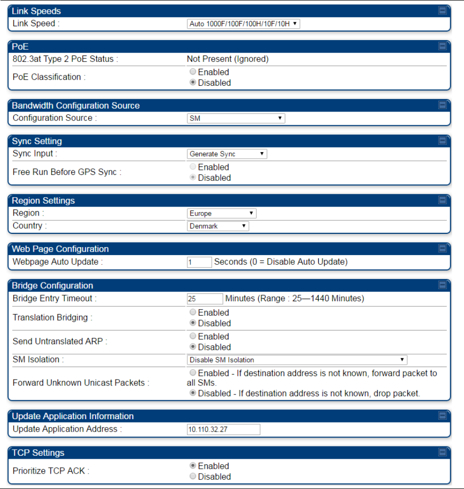
Chapter 7: Configuration
General configuration
Page 7-140
Table 104 General page attributes – PMP 450i AP / PMP 450m AP
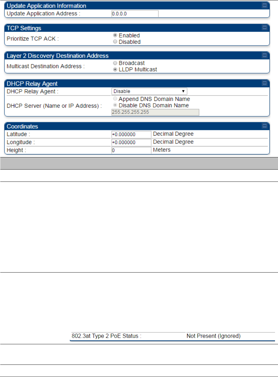
Chapter 7: Configuration
General configuration
Page 7-141
Attribute
Meaning
Device Setting
Allows the Spectrum Analyzer to be run directly from AP now.
Link Speeds
From the drop-down list of options, select the type of link speed for the
Ethernet connection. The default for this parameter is that all speeds are
selected: Auto 100F/100H/10F/10H. In this setting, the two ends of the
link automatically negotiate with each other whether the speed that they
will use is 10 Mbps or 100 Mbps and whether the Ethernet traffic is full
duplex or half duplex. However,137 Ethernet links work best when
either:
both ends are set to the same forced selection
both ends are set to auto-negotiate and both have capability in least
one common speed and traffic type combination.
802.3at Type 2 PoE
Status and
PoE Classification
When the PoE Classification functionality is enabled and if Type 2 power
is not present, the PAs do not power up and draw too much power.
By default, the PoE Classification feature is disabled and the PAs will
power up regardless of the classification presented by the power source.
This is supported only on 450i series devices.
PoE Classification configuration status also can be check under home >
General > Device Information tab:
Configuration
Source
See Setting the Configuration Source on page 7-264.
Sync Input
See Configuring synchronization on page 7-163
Chapter 7: Configuration
General configuration
Page 7-142
Device Type
Standard: The Autosync mechanism will source GPS synchronization
from the AP’s RJ-11 port, the AP’s power port, or from the device on-
board GPS module.
Remote: The Autosync mechanism will source GPS synchronization
from the AP’s RJ-11 port or from the device on-board GPS module.
Region
From the drop-down list, select the region in which the radio is
operating.
Country
From the drop-down list, select the country in which the radio is
operating.
Unlike selections in other parameters, your Country selection requires a
Save Changes and a Reboot cycle before it will force the context-
sensitive GUI to display related options (for example, Alternate
Frequency Carrier 1 and 2 in the Configuration > Radio tab).
PMP 450i equipment shipped to the United States is locked to a Region
Code setting of “United States”. Units shipped to regions other than the
United States must be configured with the corresponding Region Code
to comply with local regulatory requirements.
Country Code settings affect the radios in the following ways:
Maximum transmit power limiting (based on radio transmitter power
plus configured antenna gain)
DFS operation is enabled based on the configured region code, if
applicable
For more information on how transmit power limiting and DFS is
implemented for each country, see the PMP 450 Planning Guide.
Webpage Auto
Update
Enter the frequency (in seconds) for the web browser to automatically
refresh the web-based interface. The default setting is 0. The 0 setting
causes the web-based interface to never be automatically refreshed.
Bridge Entry
Timeout
Specify the appropriate bridge timeout for correct network operation
with the existing network infrastructure. The Bridge Entry Timeout must
be a longer period than the ARP (Address Resolution Protocol) cache
timeout of the router that feeds the network.
Caution
An inappropriately low Bridge Entry Timeout setting may
lead to temporary loss of communication with some end
users.
Translation Bridging
Optionally, you can configure the AP to change the source MAC address
in every packet it receives from its SMs to the MAC address of the SM
that bridged the packet, before forwarding the packet toward the public
network. If you do, then:
Not more than 10 IP devices at any time are valid to send data to the AP
from behind the SM.

Chapter 7: Configuration
General configuration
Page 7-143
SM populates the Translation Table tab of its Statistics web page,
displaying the MAC address and IP address of all the valid connected
devices.
Each entry in the Translation Table is associated with the number of
minutes that have elapsed since the last packet transfer between the
connected device and the SM.
If 10 are connected and another attempts to connect:
If no Translation Table entry is older than 255 minutes, the attempt is
ignored.
If an entry is older than 255 minutes, the oldest entry is removed and the
attempt is successful.
the Send Untranslated ARP parameter in the General tab of the
Configuration page can be:
Disabled, so that the AP overwrites the MAC address in Address
Resolution Protocol (ARP) packets before forwarding them.
Enabled, so that the AP forwards ARP packets regardless of whether it
has overwritten the MAC address.
When this feature is disabled, the setting of the Send Untranslated ARP
parameter has no effect, because all packets are forwarded untranslated
(with the source MAC address intact).
Send Untranslated
ARP
If the Translation Bridging parameter is set to Enabled, then the Send
Untranslated ARP parameter can be:
Disabled - so that the AP will overwrite the MAC address in Address
Resolution Protocol (ARP) packets before forwarding them.
Enabled - so that the AP will forward ARP packets regardless of whether
it has overwritten the MAC address.
If the Translation Bridging parameter is set to Disabled, then the Send
Untranslated ARP parameter has no effect.
SM Isolation
Prevent or allow SM-to-SM communication by selecting from the
following drop-down menu items:
Disable SM Isolation (the default selection). This allows full
communication between SMs.
Block SM Packets from being forwarded. This prevents both
multicast/broadcast and unicast SM-to-SM communication.
Block and Forward SM Packets to Backbone. This not only prevents
multicast/broadcast and unicast SM-to-SM communication but also
sends the packets, which otherwise are handled SM to SM, through the
Ethernet port of the AP.

Chapter 7: Configuration
General configuration
Page 7-144
Forward Unknown
Unicast Packets
Enabled: All unknown Unicast packets (no entry in the AP’s bridge table)
received via the AP’s Ethernet LAN interface are forwarded to registered
SMs. If the target device is situated beneath a particular SM, when the
device responds the SM and AP will learn and add the device to their
bridge tables so that subsequent packets to that device is bridged to the
proper SM.
Disabled: All unknown Unicast packets (no entry in the AP’s bridge table)
received via the AP’s Ethernet LAN interface are discarded at the AP.
Update Application
Address
Enter the address of the server to access for software updates on this AP
and registered SMs.
Prioritize TCP ACK
To reduce the likelihood of TCP acknowledgement packets being
dropped, set this parameter to Enabled. This can improve throughput
that the end user perceives during transient periods of congestion on the
link that is carrying acknowledgements. This parameter, when enabled,
can be particularly useful when running bi-direction FTP sessions over
the link. If a link is primarily used for video surveillance, it is
recommended to set this parameter to Disable.
Multicast Destination
Address
Using Link Layer Discovery Protocol (LLDP), a module exchanges
multicast addresses with the device to which it is wired on the Ethernet
interface. Although some switches (CMM4, for example) do not pass
LLDP addresses upward in the network, a radio can pass it as the value
of the Multicast Destination Address parameter value in the connected
device that has it populated.
DHCP Relay Agent
The AP may act as a DHCP relay for SMs and CPEs underneath it. The AP
will make use of the DHCP Option 82 (DHCP Relay Agent Information)
from RFC 3046 when performing relay functions. The AP offers two
types of DHCP relay functionality:
Full Relay Information. Configuring the DHCP Full Relay Operation will
take broadcast DHCP packets and send them to a Unicast server in
unicast mode. This way the DHCP requests and replies can be routed like
any other UDP packet.
Only Insert Option 82. This option leaves the DHCP request on its
broadcast domain as opposed to DHCP Full Relay Operation which will
turn it into a unicast packet.
In order to accommodate setting up pools or classes for different VLANs,
the Option 82 field will include information to tell the server what VLAN
the client is on.
DHCP Server (Name
or IP Address)
The DHCP relay server may be either a DNS name or a static IP address
in dotted decimal notation. Additionally the management DNS domain
name may be toggled such that the name of the DHCP relay server only
needs to be specified and the DNS domain name is automatically
appended to that name. The default DHCP relay server addresses is
255.255.255.255 with the appending of the DNS domain name disabled.
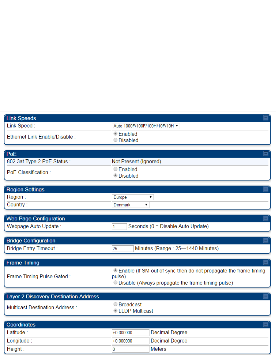
Chapter 7: Configuration
General configuration
Page 7-145
Latitude
Longitude
Height
Physical radio location data may be configured via the Latitude,
Longitude and Height fields.
Latitude and Longitude is measured in Decimal Degree while the Height
is calculated in Meters.
General page - PMP 450i SM
The General page of PMP 450i SM is explained in Table 105. The General page of PMP 450 SM
looks same as PMP 450i SM.
Table 105 General page attributes – PMP 450i SM

Chapter 7: Configuration
General configuration
Page 7-146
Attribute
Meaning
Link Speeds
From the drop-down list of options, select the type of link speed for the
Ethernet connection. The default for this parameter is that all speeds are
selected. The recommended setting is a single speed selection for all
APs and SMs in the operator network.
802.3at Type 2 PoE
Status and
PoE Classification
When the PoE Classification functionality is enabled and if Type 2 power
is not present, the PAs do not power up and draw too much power.
By default, the PoE Classification feature is disabled and the PAs will
power up regardless of the classification presented by the power source.
This is supported only on 450i series devices.
PoE Classification configuration status also can be check under home >
General > Device Information tab:
Ethernet Link
Enable/Disable
Specify whether to enable or disable Ethernet/802.3 connectivity on the
wired port of the SM. This parameter has no effect on the wireless link.
When you select Enable, this feature allows traffic on the Ethernet/802.3
port. This is the factory default state of the port. When you select
Disable, this feature prevents traffic on the port. Typical cases of when
you may want to select Disable include:
The subscriber is delinquent with payment(s).
You suspect that the subscriber is sending or flooding undesired
broadcast packets into the network, such as when
a virus is present in the subscriber's computing device.
the subscriber's home router is improperly configured.
Region
This parameter allows you to set the region in which the radio will
operate.
The SM radio automatically inherits the Region type of the master. This
behavior ignores the value of the Region parameter in the SM, even
when the value is None. Nevertheless, since future system software
releases may read the value in order to configure some other region-
sensitive feature(s), this parameter must be always set to the value that
corresponds to the local region.
Country
This parameter allows you to set the country in which the radio will
operate.
The SM radio automatically inherits the Country Code type of the
master. This behavior ignores the value of the Country parameter in the
SM, even when the value is None. Nevertheless, since future system
software releases may read the value in order to configure some other
region-sensitive feature(s), this parameter must be always set to the
value that corresponds to the local region.
Chapter 7: Configuration
General configuration
Page 7-147
PMP/PTP 450i equipment shipped to the United States is locked to a
Region Code setting of “United States”. Units shipped to regions other
than the United States must be configured with the corresponding
Region Code to comply with local regulatory requirements.
Webpage Auto
Update
See Table 104 General page attributes – PMP 450i AP on page 7-140
Bridge Entry
Timeout
Specify the appropriate bridge timeout for correct network operation
with the existing network infrastructure. Timeout occurs when the AP
encounters no activity with the SM (whose MAC address is the bridge
entry) within the interval that this parameter specifies. The Bridge Entry
Timeout must be a longer period than the ARP (Address Resolution
Protocol) cache timeout of the router that feeds the network.
Caution
This parameter governs the timeout interval, even if a
router in the system has a longer timeout interval. The
default value of this field is 25 (minutes).
An inappropriately low Bridge Entry Timeout setting may
lead to temporary loss of communication with some end
users.
Frame Timing Pulse
Gated
If this SM extends the sync pulse to a BH master or an AP, select either
Enable—If this SM loses sync from the AP, then do not propagate a sync
pulse to the BH timing master or other AP. This setting prevents
interference in the event that the SM loses sync.
Disable—If this SM loses sync from the AP, then propagate the sync
pulse to the BH timing master or other AP.
Multicast Destination
Address
Using Link Layer Discovery Protocol (LLDP), a module exchanges
multicast addresses with the device to which it is wired on the Ethernet
interface. Although some switches (CMM4, for example) do not pass
LLDP addresses upward in the network, a radio can pass it as the value
of the Multicast Destination Address parameter value in the connected
device that has it populated.
Coordinates
Physical radio location data may be configured via the Latitude,
Longitude and Height fields.
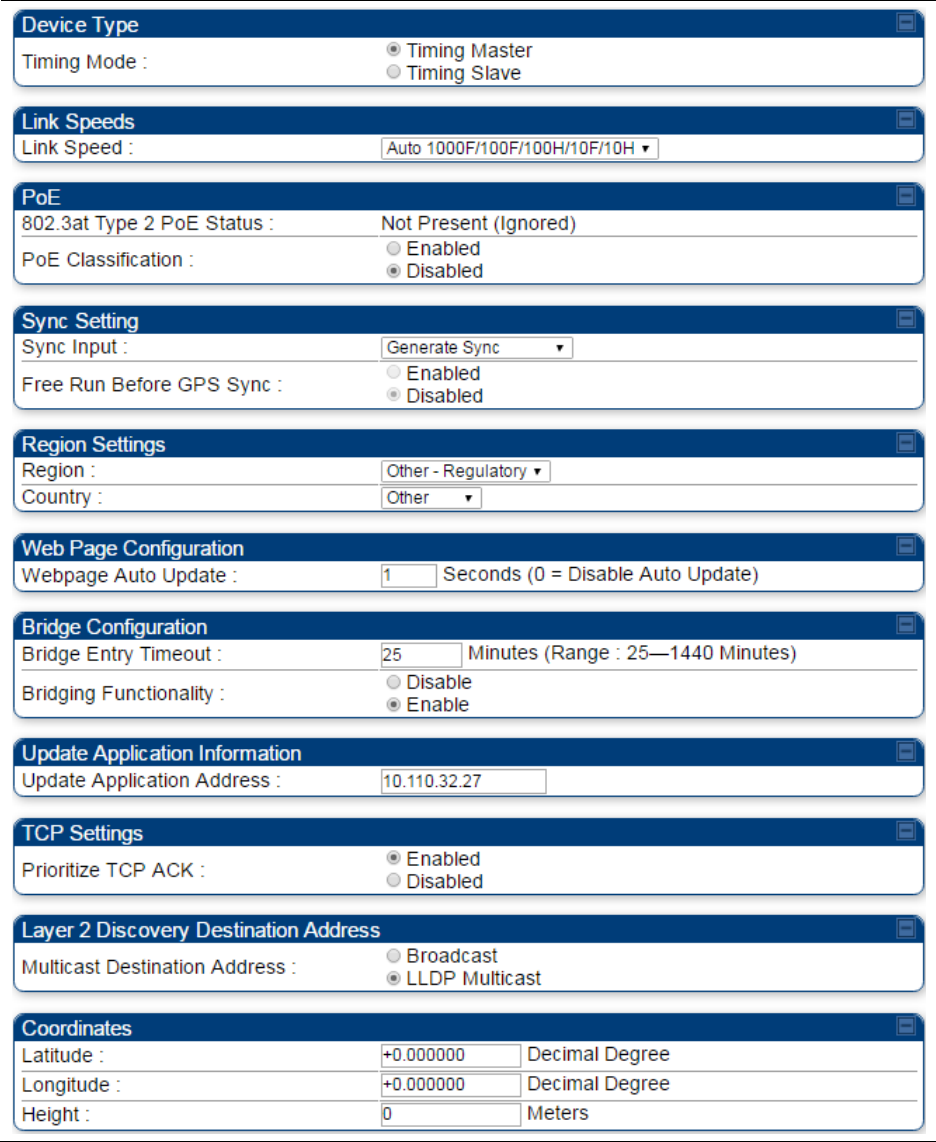
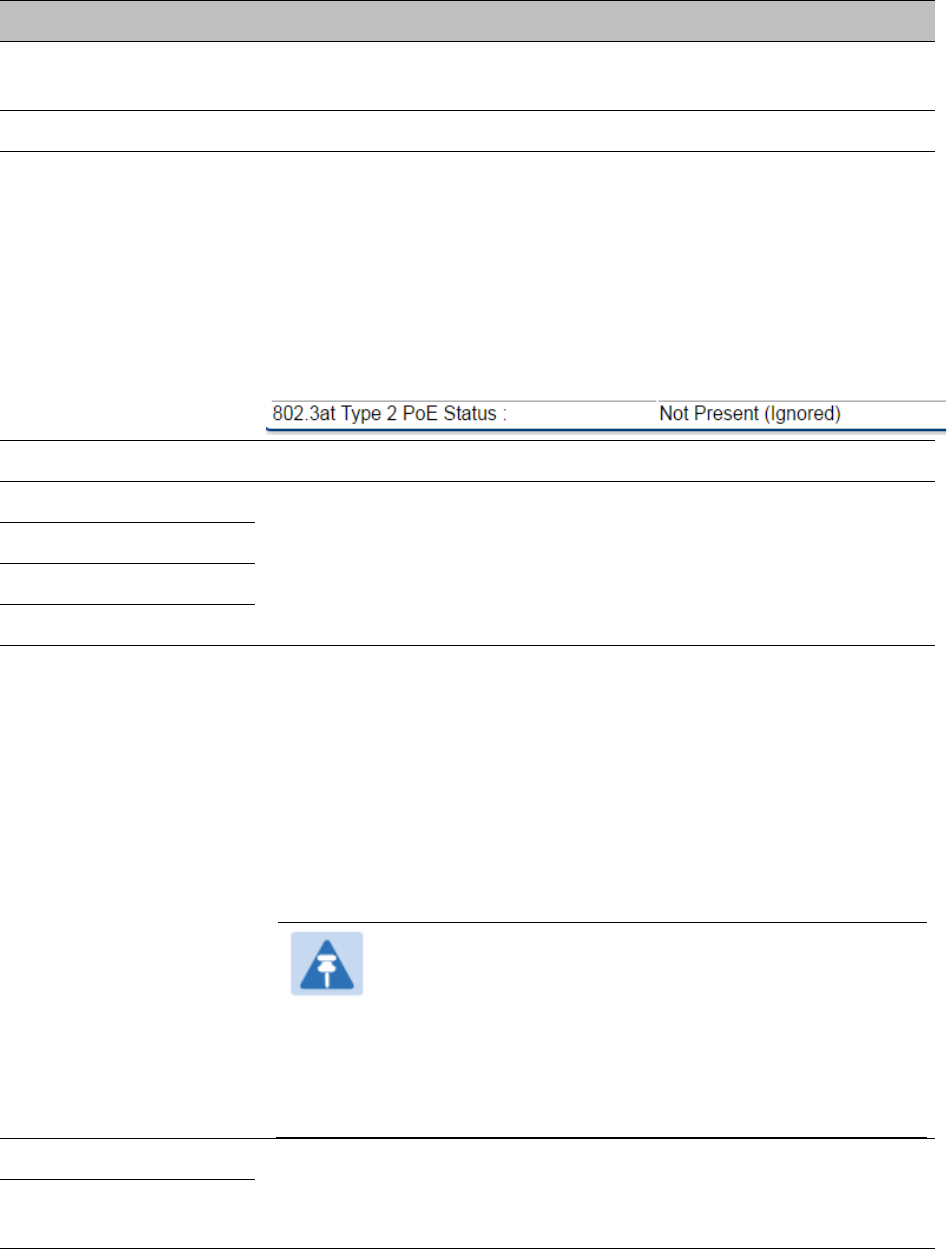
Chapter 7: Configuration
General configuration
Page 7-149
Attribute
Meaning
Timing Mode
Allows the user to choose the mode between Timing Master and
Timing Slave.
Link Speed
See Table 104 General page attributes – PMP 450i AP on page 7-140
802.3at Type 2 PoE
Status and
PoE Classification
When the PoE Classification functionality is enabled and if Type 2
power is not present, the PAs do not power up and draw too much
power.
By default, the PoE Classification feature is disabled and the PAs will
power up regardless of the classification presented by the power
source.
This is supported only on 450i series devices.
PoE Classification configuration status also can be check under home
> General > Device Information tab:
Sync Input
See Configuring synchronization on page 7-163
Region
See Table 104 General page attributes – PMP 450i AP on page 7-140
Country
Webpage Auto Update
Bridge Entry Timeout
Bridging Functionality
Select whether you want bridge table filtering active (Enable) or not
(Disable) on this BH.
Disable: allows user to use redundant BHs without causing network
addressing problems. Through a spanning tree protocol, this reduces
the convergence time from 25 minutes to few seconds. However, you
must disable bridge table filtering as only a deliberate part of your
overall network design since disabling it allows unwanted traffic
across the wireless interface.
Enable: Allows user to enable bridge functionality.
Note
Specify the appropriate bridge timeout for correct
network operation with the existing network
infrastructure. The Bridge Entry Timeout must be a
longer period than the ARP (Address Resolution
Protocol) cache timeout of the router that feeds the
network.
Prioritize TCP ACK
See Table 104 General page attributes – PMP 450i AP on page 7-140
Multicast Destination
Address
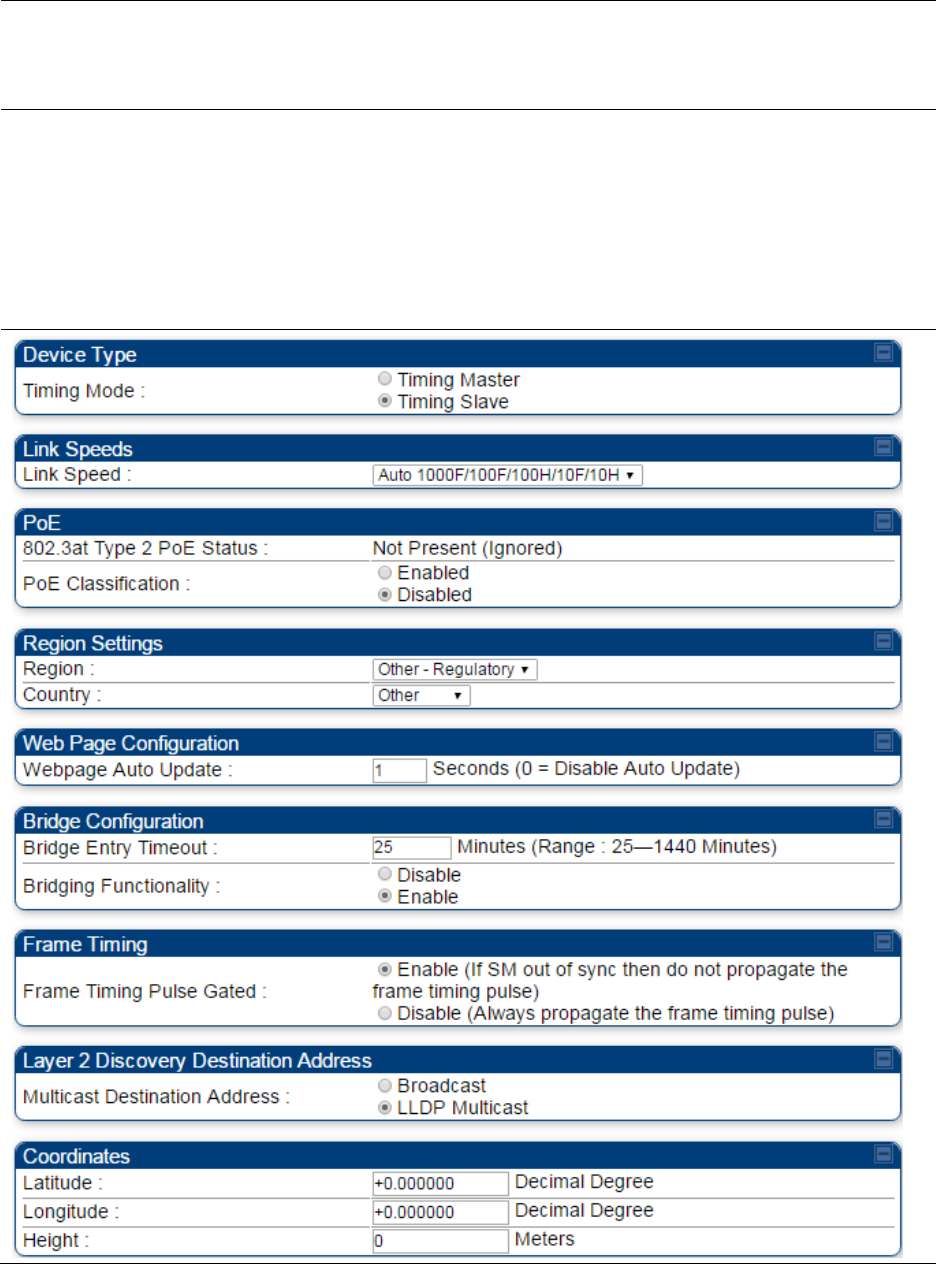
Chapter 7: Configuration
General configuration
Page 7-151
Attribute
Meaning
Timing Mode
Allows the user to choose the mode between Timing Master and Timing
Slave.
Link Speed
From the drop-down list of options, select the type of link speed for the
Ethernet connection. The default for this parameter is that all speeds are
selected. The recommended setting is a single speed selection for all
BHMs and BHSs in the operator network.
802.3at Type 2 PoE
Status and
PoE Classification
When the PoE Classification functionality is enabled and if Type 2 power
is not present, the PAs do not power up and draw too much power.
By default, the PoE Classification feature is disabled and the PAs will
power up regardless of the classification presented by the power source.
This is supported only on 450i series devices.
PoE Classification configuration status also can be check under home >
General > Device Information tab:
Region
This parameter allows you to set the region in which the radio will
operate.
The BHS radio automatically inherits the Region type of the master. This
behavior ignores the value of the Region parameter in the BHS, even
when the value is None. Nevertheless, since future system software
releases may read the value in order to configure some other region-
sensitive feature(s), this parameter must be always set to the value that
corresponds to the local region.
Country
This parameter allows you to set the country in which the radio will
operate.
The BHS radio automatically inherits the Country Code type of the
master. This behavior ignores the value of the Country parameter in the
BHS, even when the value is None. Nevertheless, since future system
software releases may read the value in order to configure some other
region-sensitive feature(s), this parameter must be always set to the
value that corresponds to the local region.
PMP/PTP 450i equipment shipped to the United States is locked to a
Region Code setting of “United States”. Units shipped to regions other
than the United States must be configured with the corresponding
Region Code to comply with local regulatory requirements.
Webpage Auto
Update
See Table 104 General page attributes – PMP 450i AP on page 7-140
Bridge Entry
Timeout
Specify the appropriate bridge timeout for correct network operation
with the existing network infrastructure. Timeout occurs when the BHM
encounters no activity with the BHS (whose MAC address is the bridge
entry) within the interval that this parameter specifies. The Bridge Entry
Timeout must be a longer period than the ARP (Address Resolution
Protocol) cache timeout of the router that feeds the network.
Chapter 7: Configuration
General configuration
Page 7-152
Caution
This parameter governs the timeout interval, even if a
router in the system has a longer timeout interval. The
default value of this field is 25 (minutes).
An inappropriately low Bridge Entry Timeout setting may
lead to temporary loss of communication with some end
users.
Bridging
Functionality
See Table 104 General page attributes – PMP 450i AP on page 7-140
Frame Timing Pulse
Gated
If this BHS extends the sync pulse to a BH master or an BHM, select
either
Enable—If this BHS loses sync from the BHM, then do not propagate a
sync pulse to the BH timing master or other BHM. This setting prevents
interference in the event that the BHS loses sync.
Disable—If this BHS loses sync from the BHM, then propagate the sync
pulse to the BH timing master or other BHM.
Multicast Destination
Address
See Table 104 General page attributes – PMP 450i AP on page 7-140
Latitude
Longitude
Height
See Table 104 General page attributes – PMP 450i AP on page 7-140
PMP/PTP 450 Series
Note
Refer Table 104 and Table 105 for PMP 450 AP/SM General page parameters details.
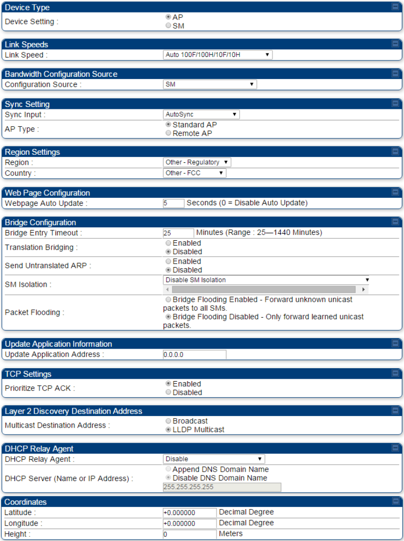
Chapter 7: Configuration
General configuration
Page 7-153
General page - PMP 450 AP
Figure 113 General page attributes - PMP 450 AP
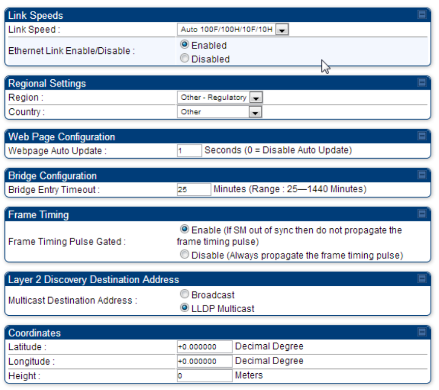
Chapter 7: Configuration
General configuration
Page 7-154
General page - PMP 450 SM
Figure 114 General page of PMP 450 SM
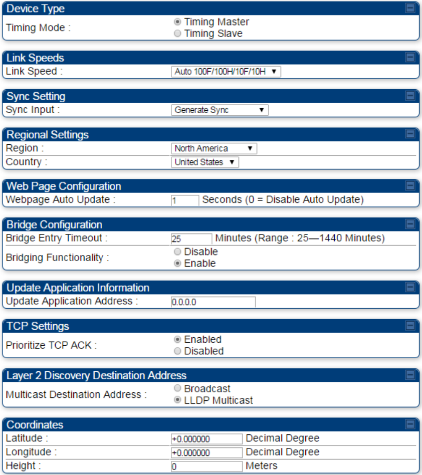
Chapter 7: Configuration
General configuration
Page 7-155
General page – PTP 450 BHM
Figure 115 General page of PTP 450 BHM
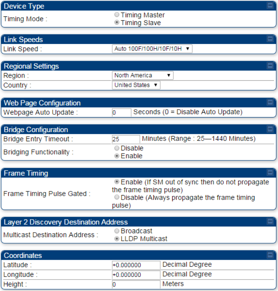
Chapter 7: Configuration
General configuration
Page 7-156
General page – PTP 450 BHS
Figure 116 General page of PTP 450 BHS

Chapter 7: Configuration
Configuring Unit Settings page
Page 7-157
Configuring Unit Settings page
Applicable products
PMP :
AP
SM
PTP:
BHM
BMS
The Unit Settings page of the PMP/PTP 450 platform contains following options:
Unit-Wide Changes
Download Configuration File
Upload and Apply Configuration File (for AP and BHM)
LED Panel Settings (for SM and BHS)
Note
LED Pannel setting is applicable for SM and BHS only.
Upload and Apply Configuration File attributes are not supported for SM and BHS.
The PMP/PTP 450 platform also supports import and export of configuration from the
AP/BHM/SM/BHS as a text file. The configuration file is in JSON format. The logged in user must
be an ADMINISTRATOR in order to export or import the configuration file.
The exported configuration file contains the complete configuration including all the default
values. To keep a backup of the current configuration, the file can be saved as-is and imported
later.
The configuration file supports encrypted password. The exported configuration file will contain
encrypted password. The import of configuration can have either encrypted or plain text password
in Configuration fie. A new tab Encrypt the Password is added under Encrypted Password tab to
generate encrypted password for a given password.
The Import and Export procedure of configuration file is described in Import and Export of config
file on page 7-279.
LED Panel Mode has options select Revised mode and Legacy mode. The Legacy mode configures
the radio to operate with standard LED behavior.
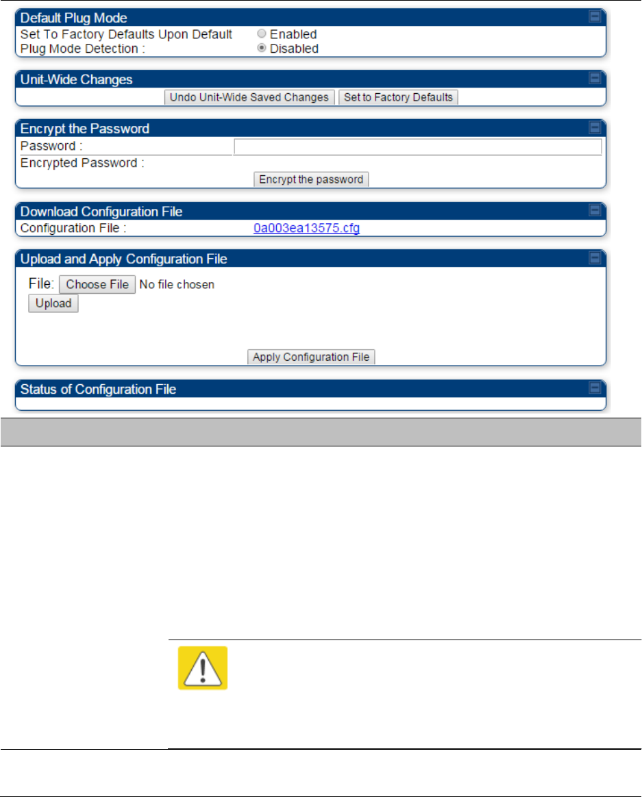
Chapter 7: Configuration
Configuring Unit Settings page
Page 7-158
Unit Settings page of PMP/PTP 450 platform AP/BHM
The Unit Setting page of AP/BHM is explained in Table 108.
Table 108 Unit Settings attributes – PMP/PTP 450 platform AP/BHM
Attribute
Meaning
Set to Factory
Defaults Upon
Default Mode
Detection
If Enabled is checked, then the default mode functions is enabled. When
the module is rebooted with Default mode enabled, it can be accessed at
the IP address 169.254.1.1 and no password, and all parameter values
are reset to defaults. A subscriber, technician, or other person who gains
physical access to the module and uses an override cannot see or learn
the settings that were previously configured in it.
If Disabled is checked, then the default mode functions is disabled.
See Radio recovery mode on page 1-22
Caution
When Set to Factory Defaults Upon Default Mode is set to
Enable, the radio does not select all of the frequencies for
Radio Frequency Scan Selection List. It needs to be selected
manually.
Undo Unit-Wide
Saved Changes
When you click this button, any changes that you made in any tab but
did not commit by a reboot of the module are undone.
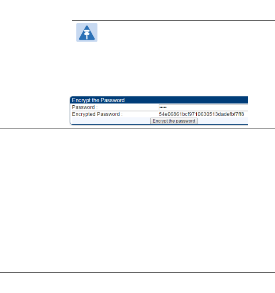
Chapter 7: Configuration
Configuring Unit Settings page
Page 7-159
Set to Factory
Defaults
When you click this button, all configurable parameters on all tabs are
reset to the factory settings.
Note
This can be reverted by selecting "Undo Unit-Wide Saved
Changes", before rebooting the radio, though this is not
recommended.
Password
This allows to provide encrypted password for a given password. On
click of ‘Encrypt the password’ button, the Encrypted Password field will
display encrypted value of entered plain text password in ‘Password’
field.
Configuration File
This allows to download the configuration file of the radio. This
configuration file contains the complete configuration including all the
default values. The configuration file is highlighted as downloadable link
and the naming convention is “<mac address of AP>.cfg”.
Apply Configuration
File
This allows to import and apply configuration to the AP.
Chose File: Select the file to upload the configuration. The configuration
file is named as “<file name>.cfg”.
Upload: Import the configuration to the AP.
Apply Configuration File: Apply the imported configuration file to the AP.
The imported configuration file may either contain a full device
configuration or a partial device configuration. If a partial configuration
file is imported, only the items contained in the file will be updated, the
rest of the device configuration parameters will remain the same.
Operators may also include a special flag in the configure file to instruct
the device to first revert to factory defaults then to apply the imported
configuration.
Status of
Configuration file
This section shows the results of the upload.
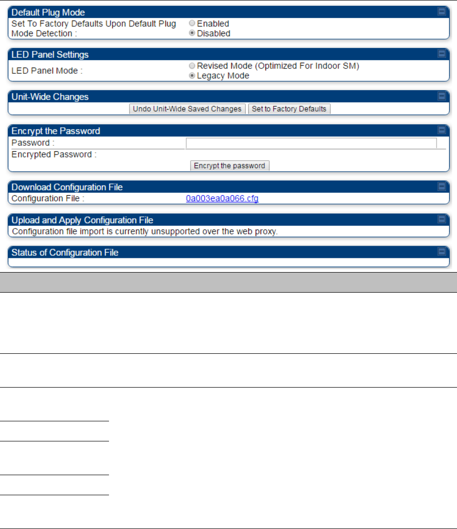
Chapter 7: Configuration
Configuring Unit Settings page
Page 7-160
Unit Settings page of PMP/PTP 450i SM/BHS
The Unit Settings page of PMP/PTP 450i SM/BHS is explained in Table 109.
Table 109 SM Unit Settings attributes
Attribute
Meaning
Set to Factory
Defaults Upon
Default Plug
Detection
See Table 108 Unit Settings attributes – PMP/PTP 450 platform AP/BHM
on page 7-158
LED Panel Settings
Legacy Mode configures the radio to operate with standard LED
behavior.
Undo Unit-Wide
Saved Changes
See Table 108 Unit Settings attributes – PMP/PTP 450 platform AP/BHM
on page 7-158
Password
Set to Factory
Defaults
Configuration File
Status of
Configuration file
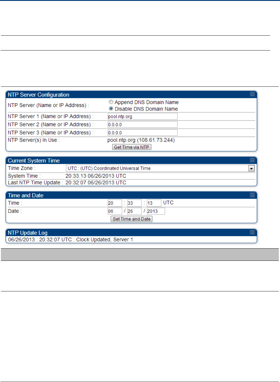
Chapter 7: Configuration
Setting up time and date
Page 7-161
Setting up time and date
Time page of PMP/PTP 450 platform AP/BHM
Applicable products
PMP :
AP
PTP:
BHM
The Time page of PMP/PTP 450 platform AP/BHM is explained in Table 110.
Table 110 PMP/PTP 450 platform AP/BHM Time attributes
Attribute
Meaning
NTP Server (Name
or IP Address)
The management DNS domain name may be toggled such that the
name of the NTP server only needs to be specified and the DNS domain
name is automatically appended to that name.
NTP Server 1 (Name
or IP Address)
NTP Server 2 (Name
or IP Address)
NTP Server 3 (Name
or IP Address)
To have each log in the AP/BHM correlated to a meaningful time and
date, either a reliable network element must pass time and date to the
AP/BHM or must set the time and date whenever a power cycle of the
AP/BHM has occurred. A network element passes time and date in any of
the following scenarios:
A connected CMM4 passes time and date (GPS time and date, if
received).
A connected CMM4 passes the time and date (GPS time and date, if
received), but only if both the CMMr is operating on CMMr Release
2.1 or later release. (These releases include NTP server functionality.)

Chapter 7: Configuration
Setting up time and date
Page 7-162
A separate NTP server (including APs/BHMs receiving NTP data) is
addressable from the AP/BHM.
If the AP/BHM needs to obtain time and date from a CMM4, or a separate
NTP server, enter the IP address or DNS name of the CMM4 or NTP
server on this tab. To force the AP/BHM to obtain time and date before
the first (or next) 15-minute interval query of the NTP server, click Get
Time via NTP.
The polling of the NTP servers is done in a sequential fashion, and the
polling status of each server is displayed in the NTP Update Log section
of the Time Configuration page. An entry of 0.0.0.0 in any of the NTP
Server fields indicates an unused server configuration.
NTP Server(s) in Use
Lists the IP addresses of servers used for NTP retrieval.
Time Zone
The Time Zone option may be used to offset the received NTP time to
match the operator’s local time zone. When set on the AP/BHM, the
offset is set for the entire sector SMs (or BHS) are notified of the current
Time Zone upon initial registration). If a Time Zone change is applied,
the SMs(or BHS) is notified of the change in a best effort fashion,
meaning some SMs//BHSs may not pick up the change until the next re-
registration. Time Zone changes are noted in the Event Log of the
AP/BHM and SM/BHS.
System Time
The current time used by the system.
Last NTP Time
Update
The last time that the system time was set via NTP.
Time
This field may be used to manually set the system time of the radio.
Date
This field may be used to manually set the system date of the radio.
NTP Update Log
This field shows NTP clock update log. It includes NTP clock update Date
and Time stamp along with server name.
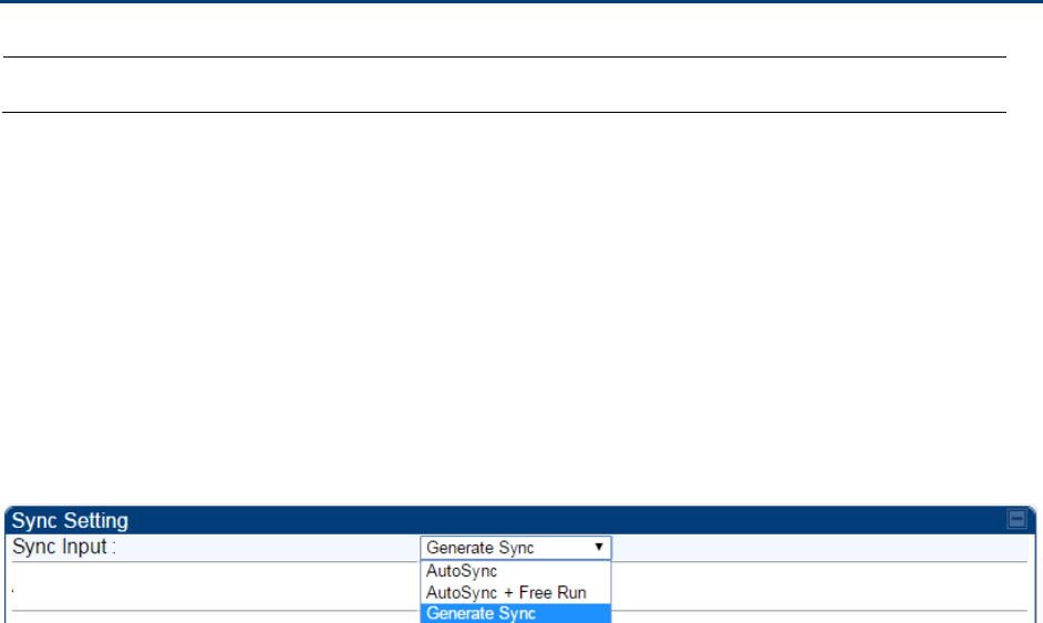
Chapter 7: Configuration
Configuring synchronization
Page 7-163
Configuring synchronization
Applicable products
PMP :
AP
PTP:
BHM
This section describe synchronization options for PMP and PTP configuration.
This Sync Input parameter can be configured under Sync Setting tab of Configure > General page
(see General configuration on page 7-139).
PMP/PTP 450i has following sysnchronization options:
AutoSync
AutoSync + Free Run
Generate Sync
Figure 117 Sync Setting configuration
AutoSync
For PTP, the BHM automatically receives sync from one of the following sources:
GPS Sync over Timing Port (UGPS, co-located AP GPS sync output, or “Remote ” Device feed
from a registered SM’s GPS sync output)
GPS Sync over Power Port (CMM4)
Upon AP/BM power on, the AP/BHM does not transmit until a valid synchronization pulse is
received from one of the sources above. If there is a loss of GPS synchronization pulse, within two
seconds the AP/BHM automatically attempts to source GPS signaling from another source.
In case of PMP, when there are synchronization sources on both the timing port and the power
port, the power port GPS source is chosen first.
If no valid GPS signal is received, the AP/BHM ceases transmission and SM/BHS registration is lost
until a valid GPS signal is received again on the AP or BHM.
AutoSync + Free Run
This mode operates similarly to mode “AutoSync”, but if a previously received synchronization
signal is lost and no GPS signaling alternative is achieved, the AP/BHM automatically changes to
synchronization mode “Generate Sync”. While SM registration ins maintained, in this mode there
is no synchronization of APs/BHMs that can “hear” each other; the AP/BHM will only generate a
sync signal for the local AP/BHM and its associated SMs/BHS. Once a valid GPS signal is obtained
again, the AP/BHM automatically switches to receiving synchronization via the GPS source and
SM/BHS registration is maintained.

Chapter 7: Configuration
Configuring synchronization
Page 7-164
When the Sync Input field is set to Autosync or Autosync + Free Run, other options become
available to be set e.g. UGPS Power and other fields. This is true on APs and BHMs.
Note
In mode AutoSync + Free Run, if a GPS signal is never achieved initially, the system
will not switch to “Free Run” mode, and SMs/BHS will not register to the AP/BHM. A
valid GPS signal must be present initially for the AP to switch into “Free Run” mode
(and to begin self-generating a synchronization pulse).
Also, When an AP/BHM is operating in “Free Run” mode, over a short time it will no
longer be synchronized with co-located or nearby APs/BHMs (within radio range).
Due to this lack of transmit and receive synchronization across APs/BHMs or across
systems, performance while in “Free Run” mode may be degraded until the
APs/BHMs operating in “Free Run” mode regain a external GPS synchronization
source. Careful attention is required to ensure that all systems are properly receiving
an external GPS synchronization pulse, and please consider “Free Run” mode as an
emergency option.
Generate Sync (factory default)
This option may be used when the AP/BHM is not receiving GPS synchronization pulses from
either a CMM4 or UGPS module, and there are no other APs/BHMs active within the link range.
Using this option will not synchronize transmission of APs/BHMs that can “hear” each other; it will
only generate a sync signal for the local AP/BHM and its associated SMs/BHS.
Note
When an AP/BHM has its "Regional Code" set to "None", The radio will not provide
valid Sync Pulse Information.
There is a RED warning that the radio will not transmit, but the user might expect to
see a valid sync if the radio is connected to a working CMM4 or UGPS.

Chapter 7: Configuration
Configuring security
Page 7-165
Configuring security
Perform this task to configure the PMP/PTP 450 platform system in accordance with the network
operator’s security policy. Choose from the following procedures:
Managing module access by password on page 7-166: to configure the unit access password
and access level
Isolating from the internet on page 7-169: to ensure that APs are properly secured from
external networks
Encrypting radio transmissions on page 7-169: to configure the unit to operate with AES or
DES wireless link security
Requiring SM Authentication on page 7-170: to set up the AP to require SMs to authenticate
via the AP, WM, or RADIUS server
Filtering protocols and ports on page 7-171: to filter (block) specified protocols and ports from
leaving the system
Encrypting downlink broadcasts on page 7-174: to encrypt downlink broadcast transmissions
Isolating SMs on page 7-174: to prevent SMs in the same sector from directly communicating
with each other
Filtering management through Ethernet on page 7-175: to prevent management access to the
SM via the radio’s Ethernet port
Allowing management only from specified IP addresses on page 7-175: to only allow radio
management interface access from specified IP addresses
Restricting radio Telnet access over the RF interface on page 7-175: to restrict Telnet access to
the AP
Configuring SNMP Access on page 7-178
Configuring Security on page 7-180
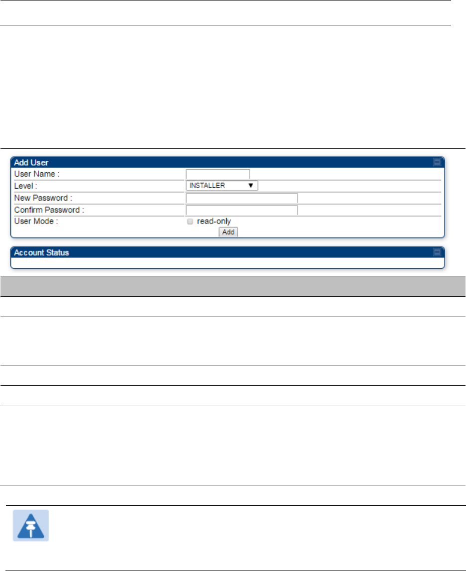
Chapter 7: Configuration
Configuring security
Page 7-166
Managing module access by password
Applicable products
PMP :
AP
SM
PTP:
BHM
BMS
See Managing module access by passwords on page 3-37.
Adding a User for Access to a module
The Account > Add User page allows to create a new user for accessing PMP/PTP 450 platform
AP/SM/BHM/BHS. The Add User page is explained in Table 111.
Table 111 Add User page of account page - AP/ SM/BH
Attribute
Meaning
User Name
User Account name.
Level
Select appropriate level for new account. It can be INSTALLER,
ADMINISTRATOR or TECHNICIAN. See Managing module access by
passwords on page 3-37.
New Password
Assign the password for new user account
Confirm Password
This new password must be confirmed in the “Confirm Password” field.
User Mode
User Mode is used to create an account which are mainly used for
viewing the configurations.
The local and remote Read-Only user account can be created by
“Admin”, “Installer” or “Tech” logins. To create a Read-Only user, the
“read-only” check box needs to be checked.
Note
The Read-Only user cannot perform any service impacting operations like creating
read-only accounts, editing and viewing read-only user accounts, changes in login
page, read-only user login, Telnet access, SNMP, RADIUS and upgrade/downgrade.
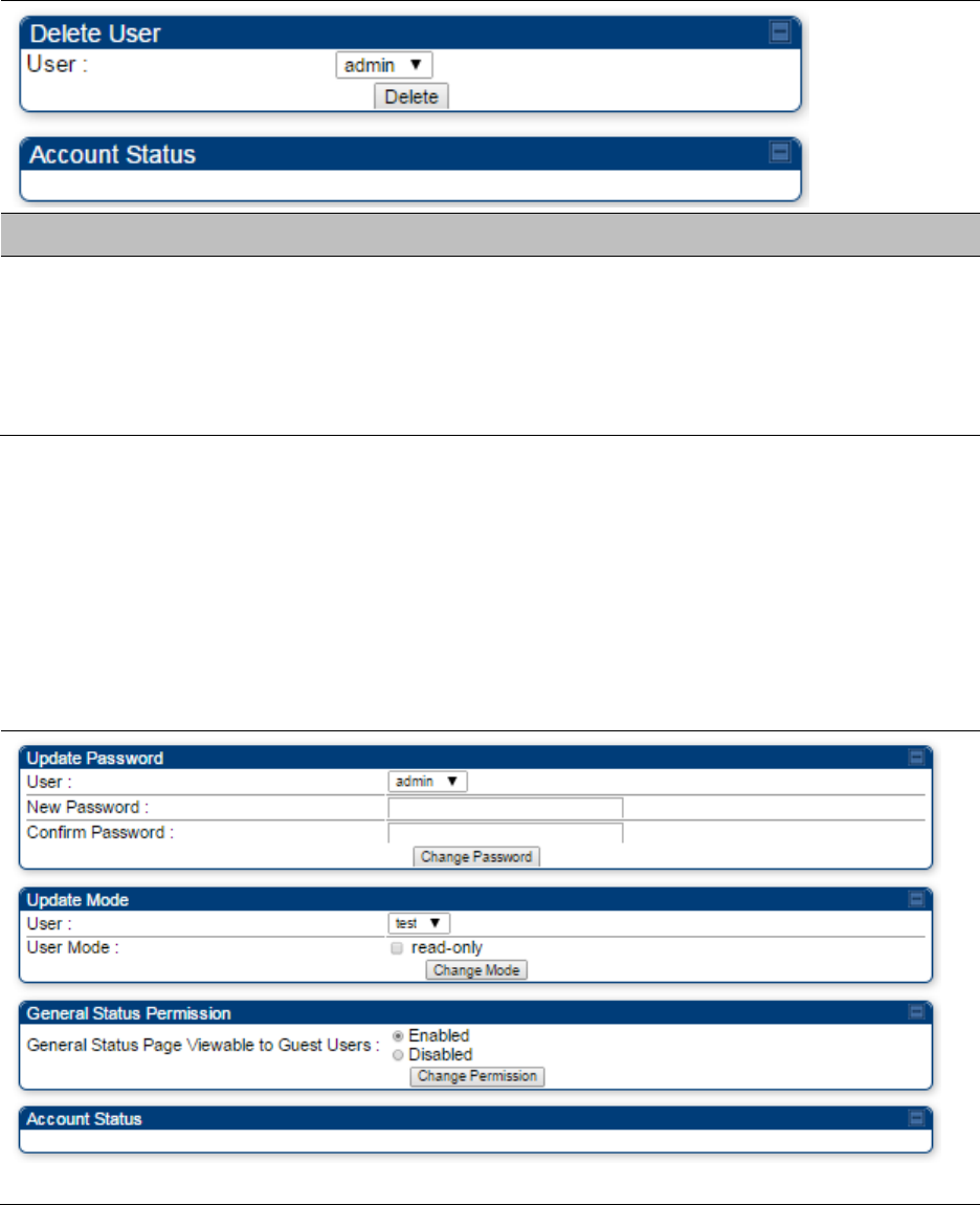
Chapter 7: Configuration
Configuring security
Page 7-167
Deleting a User from Access to a module
The Account > Delete User page provides a drop down list of configured users from which to
select the user you want to delete. The Delele User page is explained in Table 112.
Table 112 Delete User page - PMP/PTP 450 platform AP/ SM/BH
Attribute
Meaning
User
Select a user from drop down list which has to be deleted and click
Delete button.
Accounts that cannot be deleted are
the current user's own account.
the last remaining account of ADMINISTRATOR level.
Changing a User Setting
The Account > Change User Setting page allows to update password, mode update and general
status permission for a user.
From the factory default state, configure passwords for both the root and admin account at the
ADMINISTRATOR permission level, using Update Password tab of Change Users Setting page.
The Change User Setting page is explained in Table 113.
Table 113 Change User Setting page - PMP/PTP 450 platform AP/ SM/BH
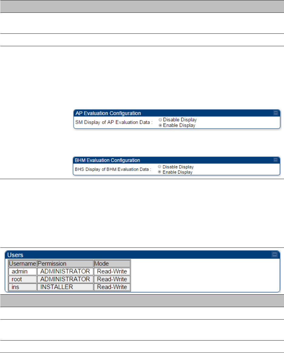
Chapter 7: Configuration
Configuring security
Page 7-168
Attribute
Meaning
Update Password
tab
This tab provides a drop down list of configured users from which a user
is selected to change password.
Update Mode tab
This tab facilitates to convert a configured user to a Read-Only user.
General Status
Permission tab
This tab enables and disables visibility of General Status Page for all
Guest user.
To display of Radio data on SMs/BHS main Login page for Guest login, it
can be enabled or disabled in Security tab of Configuration page.
Figure 118 AP Evaluation Configuration parameter of Security tab for
PMP
Figure 119 BHM Evaluation Configuration parameter of Security tab for
PTP
Users account
The Account > Users page allows to view all configured users account for accessing the module.
The Users page is explained in Table 114.
Table 114 User page – PMP/PTP 450 platform AP/SM/BH
Attribute
Meaning
Username
User access account name
Permission
Permission of configured user – INSTALLER, ADMINISTRATOR or
TECHNICIAN
Mode
This field indicate access mode of user – Read-Write or Read-Only.

Chapter 7: Configuration
Configuring security
Page 7-169
Overriding Forgotten IP Addresses or Passwords on AP and SM
See Radio recovery mode on page 1-22
Isolating from the internet – APs/BHMs
Applicable products
PMP :
AP
PTP:
BHM
See Isolating AP/BHM from the Internet on page 3-35.
Encrypting radio transmissions
Applicable products
PMP :
AP
SM
PTP:
BHM
BMS
See Encrypting radio transmissions on page 3-35.

Chapter 7: Configuration
Configuring security
Page 7-170
Requiring SM Authentication
Applicable products
PMP :
AP
SM
Through the use of a shared AP key, or an external RADIUS (Remote Authentication Dial In User
Service) server, it enhances network security by requiring SMs to authenticate when they register.
For descriptions of each of the configurable security parameters on the AP, see Configuring
Security on page 7-180. For descriptions of each of the configurable security parameters on the
SM, see Security on page 7-185.
Operators may use the AP’s Authentication Mode field to select from among the following
authentication modes:
Disabled—the AP requires no SMs to authenticate (factory default setting).
Authentication Server —the AP requires any SM that attempts registration to be authenticated
in Wireless Manager before registration
AP PreShared Key - The AP acts as the authentication server to its SMs and will make use of a
user-configurable pre-shared authentication key. The operator enters this key on both the AP
and all SMs desired to register to that AP. There is also an option of leaving the AP and SMs at
their default setting of using the “Default Key”. Due to the nature of the authentication
operation, if you want to set a specific authentication key, then you MUST configure the key on
all of the SMs and reboot them BEFORE enabling the key and option on the AP. Otherwise, if
you configure the AP first, none of the SMs is able to register.
RADIUS AAA - When RADIUS AAA is selected, up to 3 Authentication Server (RADIUS Server)
IP addresses and Shared Secrets can be configured. The IP address(s) configured here must
match the IP address(s) of the RADIUS server(s). The shared secret(s) configured here must
match the shared secret(s) configured in the RADIUS server(s). Servers 2 and 3 are meant for
backup and reliability, not for splitting the database. If Server 1 doesn’t respond, Server 2 is
tried, and then server 3. If Server 1 rejects authentication, the SM is denied entry to the
network, and does not progress trying the other servers.
For more information on configuring the PMP 450 network to utilize a RADIUS server, see
Configuring a RADIUS server on page 7-281.
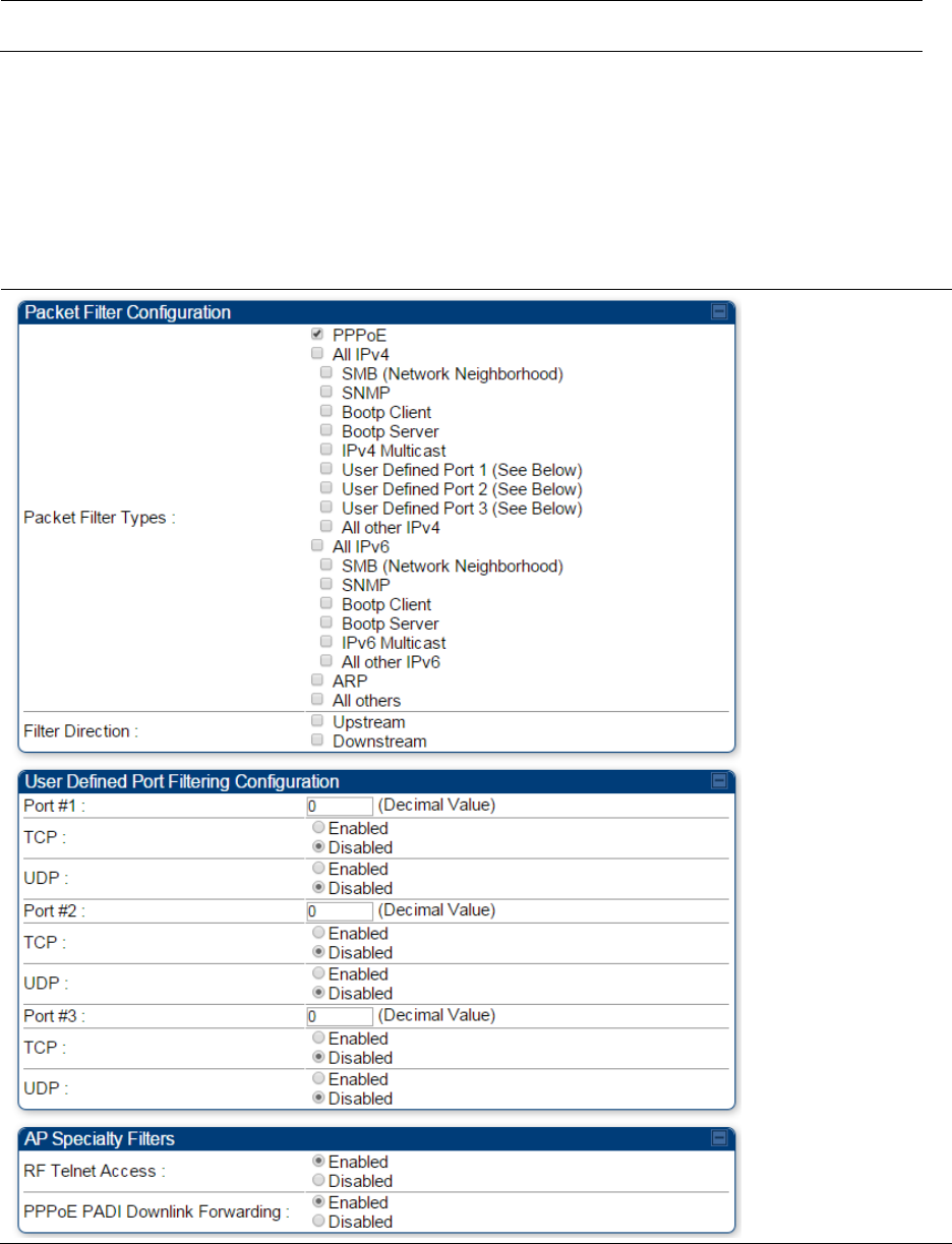
Chapter 7: Configuration
Configuring security
Page 7-171
Filtering protocols and ports
Applicable products
PMP :
AP
SM
PTP:
BHM
BMS
The filtering protocols and ports allows to configure filters for specified protocols and ports from
leaving the AP/SM/BHM/BHS and entering the network. See Filtering protocols and ports on page
3-38.
Protocol filtering page of PMP/PTP 450 platform AP/BHM
The Protocol Filtering page of PMP/PTP 450 platform AP/BHM is explained in Table 115.
Table 115 AP/BHM Protocol Filtering attributes

Chapter 7: Configuration
Configuring security
Page 7-172
Attribute
Meaning
Packet Filter Types
For any box selected, the Protocol and Port Filtering feature blocks the
associated protocol type.
To filter packets in any of the user-defined ports, must do all of the
following:
Check the box for User Defined Port n (See Below) in the Packet Filter
Types section of this tab.
In the User Defined Port Filtering Configuration section of this tab:
provide a port number at Port #n.
enable TCP and/or UDP by clicking the associated radio button
Filter Direction
Operators may choose to filter upstream (uplink) RF packets or
downstream (downlink) RF packets.
User Defined Port
Filtering
Configuration
You can specify ports for which to block subscriber access, regardless of
whether NAT is enabled.
RF Telnet Access
RF Telnet Access restricts Telnet access to the AP/BHM from a device
situated below a network SM/BHS (downstream from the AP/BHM). This
is a security enhancement to restrict RF-interface sourced AP access
specifically to the LAN1 IP address and LAN2 IP address (Radio Private
Address, typically 192.168.101.[LUID]). This restriction disallows
unauthorized users from running Telnet commands on the AP/BHM that
can change AP/BHM configuration or modifying network-critical
components such as routing and ARP tables.
PPPoE PADI
Downlink
Forwarding
Enabled: the AP/BHM allows downstream and upstream transmission of
PPPoE PADI packets. By default, PPPoE PADI Downlink Forwarding is set
to “Enabled”.
Disabled: the AP/BHM disallows PPPoE PADI packets from entering the
Ethernet interface and exiting the RF interface (downstream to the
SM/BHS). PPPoE PADI packets are still allowed to enter the AP’s RF
interface and exit the AP’s /BHM’s Ethernet interface (upstream).
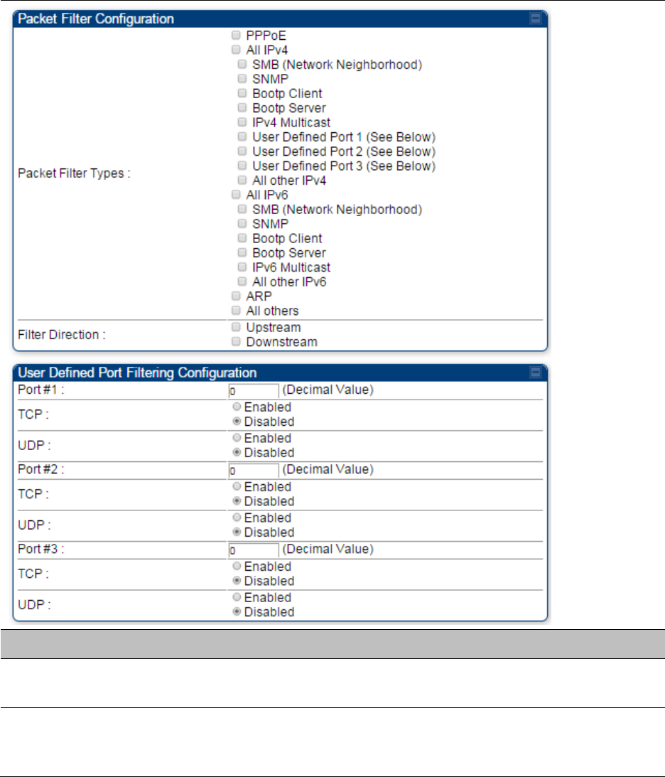
Chapter 7: Configuration
Configuring security
Page 7-173
Protocol filtering page of SM/BHS
The Protocol Filtering page of SM/BHS is explained in Table 116.
Table 116 SM/BHS Protocol Filtering attributes
Attribute
Meaning
Packet Filter
Configuration tab
See Table 115 AP/BHM Protocol Filtering attributes on page 7-171
User Defined Port
Filtering
Configuration tab
See Table 115 AP/BHM Protocol Filtering attributes on page 7-171
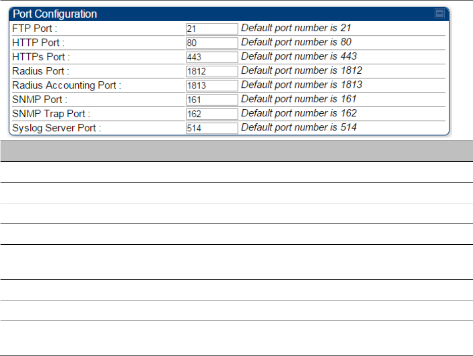
Chapter 7: Configuration
Configuring security
Page 7-174
Port configuration
PMP/PTP 450 platform devices support access to various communication protocols and only the
ports required for these protocols are available for access by external entities. Operators may
change the port numbers for these protocols via the radio GUI or SNMP.
The Port Configuration page of the AP/SM/BHM/BHS is explained in Table 117.
Table 117 Port Configuration attributes – AP/SM/BHM/BMS
Attribute
Meaning
FTP Port
The listen port on the device used for FTP communication.
HTTP Port
The listen port on the device used for HTTP communication.
HTTPS Port
The listen port on the device used for HTTPS communication
Radius Port
The destination port used by the device for RADIUS communication.
Radius Accounting
Port
The destination port used by the device for RADIUS accounting
communication.
SNMP Port
The listen port on the device used for SNMP communication.
SNMP Trap Port
The destination port used by the device to which SNMP traps are sent.
Syslog Server Port
The destination port used by the device to which Syslog messaging is
sent.
Encrypting downlink broadcasts
See Encrypting downlink broadcasts on page 3-42.
Isolating SMs
See Isolating SMs in PMP on page 3-42.
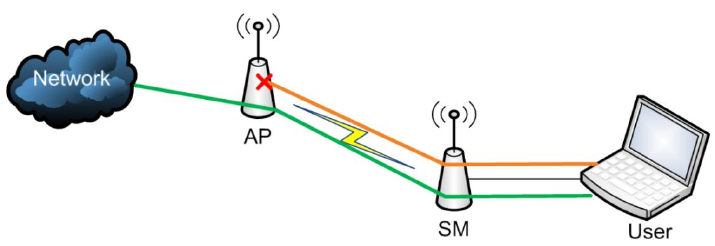
Chapter 7: Configuration
Configuring security
Page 7-175
Filtering management through Ethernet
See Filtering management through Ethernet on page 3-42.
Allowing management only from specified IP addresses
See Allowing management from only specified IP addresses on page 3-43.
Restricting radio Telnet access over the RF interface
RF Telnet Access restricts Telnet access to the AP from a device situated below a network SM
(downstream from the AP). This is a security enhancement to restrict RF-interface sourced AP
access specifically to the LAN1 IP address and LAN2 IP address (Radio Private Address, typically
192.168.101. [LUID]). This restriction disallows unauthorized users from running Telnet commands
on the AP that can change AP configuration or modifying network-critical components such as
routing and ARP tables.
The RF Telnet Access may be configured via the AP GUI or via SNMP commands, and RF Telnet
Access is set to “Enabled” by default. Once RF Telnet Access is set to “Disabled”, if there is a
Telnet session attempt to the AP originating from a device situated below the SM (or any
downstream device), the attempt is dropped. This also includes Telnet session attempts originated
from the SM’s management interface (if a user has initiated a Telnet session to a SM and attempts
to Telnet from the SM to the AP). In addition, if there are any active Telnet connections to the AP
originating from a device situated below the SM (or any downstream device), the connection is
dropped. This behavior must be considered if system administrators use Telnet downstream from
an AP (from a registered SM) to modify system parameters.
Setting RF Telnet Access to “Disabled” does not affect devices situated above the AP from
accessing the AP via Telnet, including servers running the CNUT (Canopy Network Updater tool)
application. Also, setting RF Telnet Access to “Disabled” does not affect any Telnet access into
upstream devices (situated above or adjacent to the AP) through the AP (see Figure 120).
The figure below depicts a user attempting two telnet sessions. One is targeted for the AP (orange)
and one is targeted for the network upstream from the AP (green). If RF Telnet Access is set to
“Disabled” (factory default setting), the Telnet attempt from the user to the AP is blocked, but the
attempt from the user to Network is allowed to pass through the Cambium network.
Figure 120 RF Telnet Access Restrictions (orange) and Flow through (green)
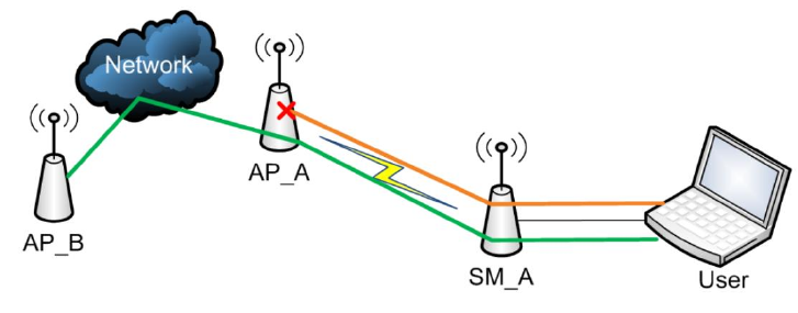
Chapter 7: Configuration
Configuring security
Page 7-176
Key Security Considerations when using the RF Telnet Access Feature
To ensure that the network is fully protected from unauthorized AP Telnet sessions, the following
topics must be considered:
Securing AP Clusters
When working with a cluster of AP units, to eliminate potential security holes allowing Telnet
access, ensure that the RF Telnet Access parameter is set to “Disabled” for every AP in the cluster.
In addition, since users situated below the AP are able to pass Telnet sessions up through the SM
and AP to the upstream network (while AP RF Telnet Access is set to “Disabled”), ensure that all
CMM4 or other networking equipment is secured with strong passwords. Otherwise, users may
Telnet to the CMM4 or other networking equipment, and subsequently access network APs (see
Figure 121) via their Ethernet interfaces (since RF Telnet Access only prevents Telnet sessions
originating from the AP’s wireless interface).
Figure 121 RF Telnet Access Restriction (orange) and Potential Security Hole (green)
As a common practice, AP administrator usernames and passwords must be secured with strong,
non-default passwords.
Restricting AP RF Telnet Access
AP Telnet access via the RF interface may be configured in two ways – the AP GUI and SNMP.
Controlling RF Telnet Access via the AP GUI
To restrict all Telnet access to the AP via the RF interface from downstream devices, follow these
instructions using the AP GUI:
Procedure 20 Restricting RF Telnet access
1
Log into the AP GUI using administrator credentials
2
On the AP GUI, navigate to Configuration > Protocol Filtering
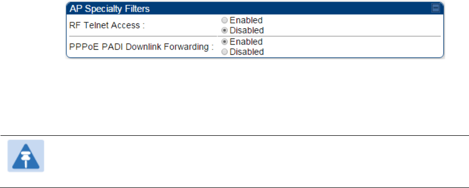
Chapter 7: Configuration
Configuring security
Page 7-177
3
Under GUI heading “Telnet Access over RF Interface”, set RF Telnet Access to Disabled
4
Click the Save button
5
Once the Save button is clicked, all RF Telnet Access to the AP from devices situated
below the AP is blocked.
Note
The factory detafult setting for RF Telnet Access is disabled and PPPoE PADI
Downlink Forwarding is enabled.
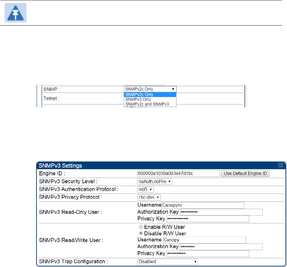
Chapter 7: Configuration
Configuring security
Page 7-178
Configuring SNMP Access
The SNMPv3 interface provides a more secure method to perform SNMP operations. This
standard provides services for authentication, data integrity and message encryption over SNMP.
Refer to Planning for SNMPv3 operation on page 3-36 for details.
Note
The factory detafult setting for SNMP is “SNMPv2c Only”.
Procedure 21 Configuring SNMPv3
1
Log into the AP GUI using administrator credentials
2
On the AP/SM GUI, navigate to Configuration > Security Page
3
Under GUI heading “Security Mode”, set SNMP to SNMPv3 Only
4
Click the Save Changes button
5
Go to Configuration > SNMP Page
6
Under GUI heading “SNMPv3 setting”, set Engine ID, SNMPv3 Security Level, SNMPv3
Authentication Protocol, SNMPv3 Privacy Protocol, SNMPv3 Read-Only User, SNMPv3
Read/Write User, SNMPv3 Trap Configuration parameters:
Engine ID :
Each radio (AP/SM/BHM/BHS) has a distinct SNMP authoritative engine identified by a
unique Engine ID. While the Engine ID is configurable to the operator it is expected that
the operator follow the guidelines of the SNMPEngineID defined in the SNMP-
FRAMEWORK-MIB (RFC 3411). The default Engine ID is the MAC address of the device.
SNMPv3 security level, Authentication and Privacy Protocol
The authentication allows authentication of SNMPv3 user and privacy allows for
encryption of SNMPv3 message. PMP/PTP 450 platform supports MD5 authentication
and CBC-DES privacy protocols.

Chapter 7: Configuration
Configuring security
Page 7-179
SNMPv3 Read-Only and Read/Write User
The user can defined by configurable attributes. The attributes and default values are:
Read-only user
o Username = Canopyro
o Authentication Password = authCanopyro
o Privacy Password = privacyCanopyro
Read-write user (by default read-write user is disabled)
o Username = Canopy
o Authentication Password = authCanopy
o Privacy Password = privacyCanopy
SNMPv3 Trap Configuration
The traps may be sent from radios in SNMPv3 format based on parameter settings. It
can be configured for Disabled, Enabled for Read-Only User, Enable for Read/Write
User.
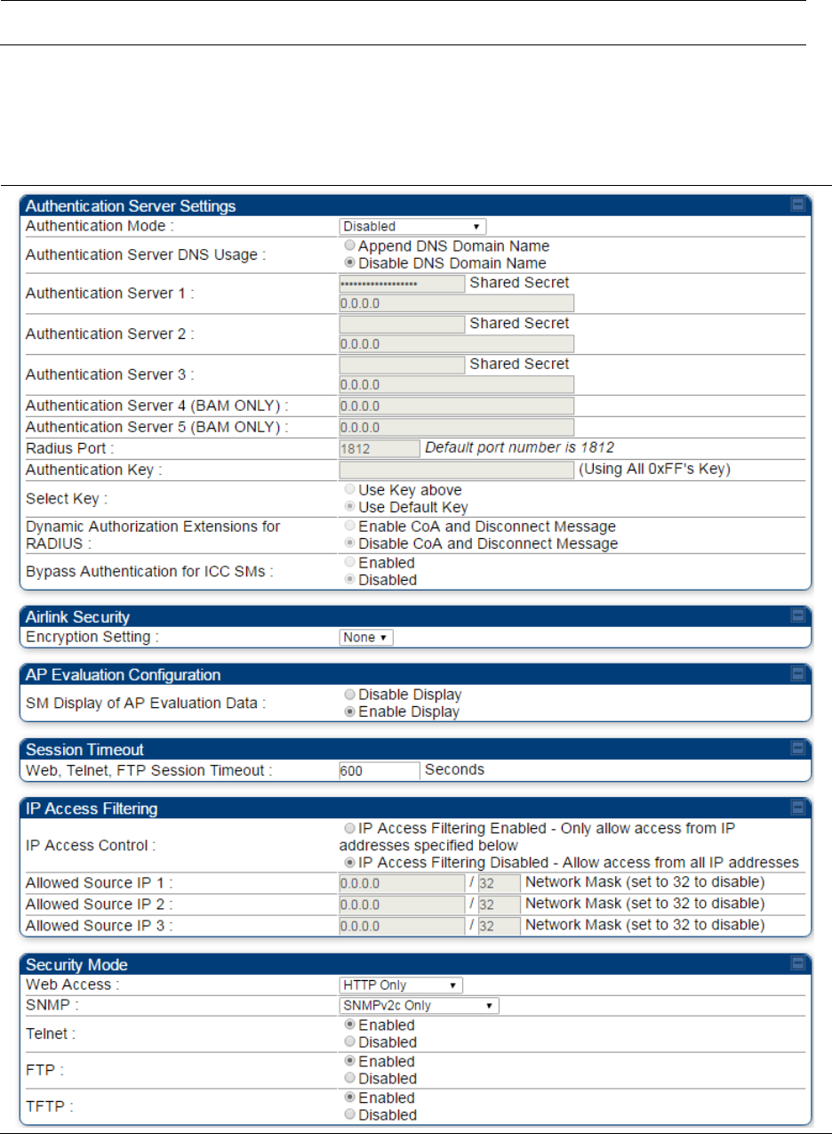
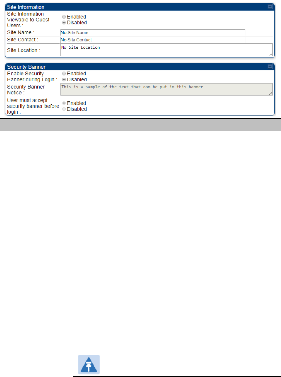
Chapter 7: Configuration
Configuring security
Page 7-181
Attribute
Meaning
Authentication Mode
Operators may use this field to select from among the following
authentication modes:
Disabled—the AP/BHM requires no SMs/BHS to authenticate. (Factory
default).
Authentication Server —the AP/BHM requires any SM/BHS that attempts
registration to be authenticated in Wireless Manager before registration.
AP PreShared Key - The AP/BHM acts as the authentication server to its
SMs/BHS and will make use of a user-configurable pre-shared
authentication key. The operator enters this key on both the AP/BHM and
all SMs/BHS desired to register to that AP/BHM. There is also an option
of leaving the AP/BHM and SMs/BHS at their default setting of using the
“Default Key”. Due to the nature of the authentication operation, if you
want to set a specific authentication key, then you MUST configure the
key on all of the SMs/BHS and reboot them BEFORE enabling the key
and option on the AP/BHM. Otherwise, if you configure the AP/BHM first,
none of the SMs/BHS is able to register.
RADIUS AAA - When RADIUS AAA is selected, up to 3 Authentication
Server (RADIUS Server) IP addresses and Shared Secrets can be
configured. The IP address(s) configured here must match the IP
address(s) of the RADIUS server(s). The shared secret(s) configured
here must match the shared secret(s) configured in the RADIUS
server(s). Servers 2 and 3 are meant for backup and reliability, not for
splitting the database. If Server 1 doesn’t respond, Server 2 is tried, and
then server 3. If Server 1 rejects authentication, the SM is denied entry
to the network, and does not progress trying the other servers.
Note
This parameter is applicable to BHM.
Chapter 7: Configuration
Configuring security
Page 7-182
Authentication
Server DNS Usage
The management DNS domain name may be toggled such that the
name of the authentication server only needs to be specified and the
DNS domain name is automatically appended to that name.
Note
This parameter is applicable to BHM.
Authentication
Server 1 to 5
Enter the IP address or server name of the authentication server
(RADIUS or WM) and the Shared Secret configured in the authentication
server. When Authentication Mode RADIUS AAA is selected, the default
value of Shared Secret is “CanopySharedSecret”. The Shared Secret
may consist of up to 32 ASCII characters.
Note
This parameter is applicable to BHM.
Radius Port
This field allows the operator to configure a custom port for RADIUS
server communication. The default value is 1812.
Note
This parameter is applicable to BHM.
Authentication Key
The authentication key is a 32-character hexadecimal string used when
Authentication Mode is set to AP PreShared Key. By default, this key is
set to 0xFFFFFFFFFFFFFFFFFFFFFFFFFFFFFFFF.
Note
This parameter is applicable to BHM.
Select Key
This option allows operators to choose which authentication key is used:
Use Key above means that the key specified in Authentication Key is
used for authentication
Use Default Key means that a default key (based off of the SM’s MAC
address) is used for authentication
Note
This parameter is applicable to BHM.
Dyanamic
Authorization
Extensions for
RADIUS
Enable CoA and Disconnect Message: Allows to control configuration
parameters of SM using RADIUS CoA and Disconnect Message feature.
Disable CoA and Disconnect Message: Disables RADIUS CoA and
Disconnect Message feature.
To enable CoA and Disconnect feature, the Authentication Mode should
be set to RADIUS AAA.
Bypass
Authentication for
ICC SMs
Enabled: SM authentication is disabled when SM connects via ICC
(Installation Color Code).
Disabled: SM authentication is enabled.
Encryption Setting
Specify the type of airlink security to apply to this AP. The encryption
setting must match the encryption setting of the SMs.
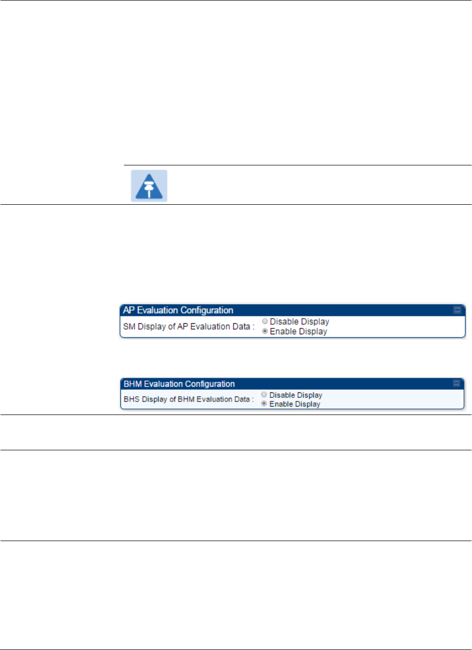
Chapter 7: Configuration
Configuring security
Page 7-183
None provides no encryption on the air link.
DES (Data Encryption Standard): An over-the-air link encryption option
that uses secret 56-bit keys and 8 parity bits. DES performs a series of bit
permutations, substitutions, and recombination operations on blocks of
data. DES encryption does not affect the performance or throughput of
the system.
AES (Advanced Encryption Standard): An over-the-air link encryption
option that uses the Rijndael algorithm and 128-bit keys to establish a
higher level of security than DES. AES products are certified as
compliant with the Federal Information Processing Standards (FIPS 197)
in the U.S.A.
Note
This parameter is applicable to BHM.
SM Display of AP
Evaluation Data
Or
BHS Display of BHM
Evaluation Data
Allows operators to suppress the display of data about this AP/BHM on
the AP/BHM Evaluation tab of the Tools page in all SMs/BHS that
register. The factory default setting for SM Display of AP Evaluation Data
or BHS Display of BHM Evaluation Data is enabled display.
PMP 450/450i – SM display of AP Evaluation Data parameter
PTP 450/450i – BHS display of BHM Evaluation Data parameter
Web, Telnet, FTP
Session Timeout
Enter the expiry in seconds for remote management sessions via HTTP,
telnet, or ftp access to the AP/BHM.
IP Access Control
You can permit access to the AP/BHM from any IP address (IP Access
Filtering Disabled) or limit it to access from only one, two, or three IP
addresses that you specify (IP Access Filtering Enabled). If you select IP
Access Filtering Enabled, then you must populate at least one of the
three Allowed Source IP parameters or have no access permitted from
any IP address
Allowed Source IP 1
to 3
If you selected IP Access Filtering Enabled for the IP Access Control
parameter, then you must populate at least one of the three Allowed
Source IP parameters or have no access permitted to the AP from any IP
address. You may populate as many as all three.
If you selected IP Access Filtering Disabled for the IP Access Control
parameter, then no entries in this parameter are read, and access from
all IP addresses is permitted.

Chapter 7: Configuration
Configuring security
Page 7-184
Web Access
The Radio supports secured and non-secured web access protocols.
Select suitable web access from drop down list:
HTTP Only – provides non-secured web access. The radio to be
accessed via http://<IP of Radio>.
HTTPS Only – provides a secured web access. The radio to be
accessed via https://<IP of Radio>.
HTTP and HTTPS – If enabled, the radio can be accessed via both
http and https.
SNMP
This option allows to configure SNMP agent communication version. It
can be selected from drop down list :
SNMPv2c Only – Enables SNMP v2 community protocol.
SNMPv3 Only – Enables SNMP v3 protocol. It is a secured
communication protocol.
SNMPv2c and SNMPv3 – It enables both the protocols.
Telnet
This option allows to Enable and Disable Telnet access to the Radio.
FTP
This option allows to Enable and Disable FTP access to the Radio.
TFTP
This option allows to Enable and Disable TFTP access to the Radio.
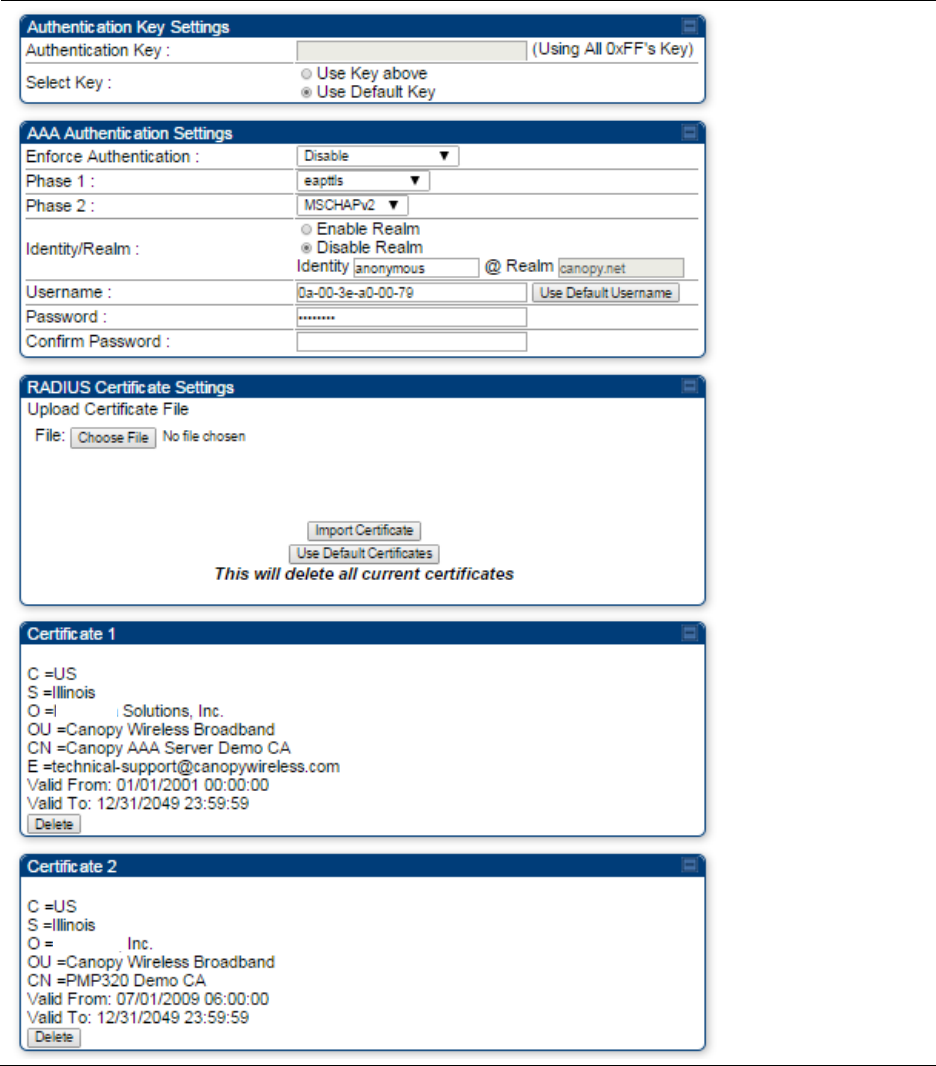
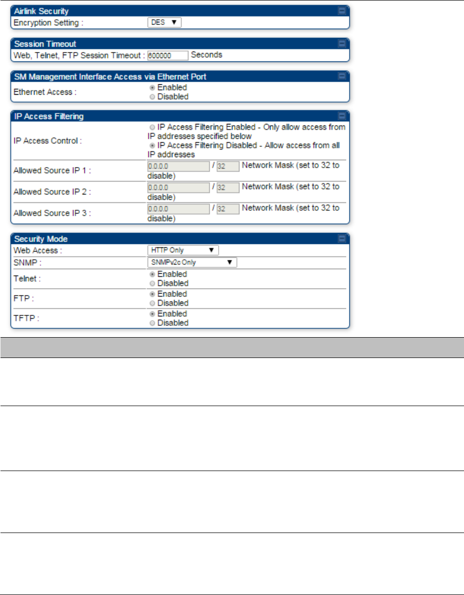
Chapter 7: Configuration
Configuring security
Page 7-186
Attribute
Meaning
Authentication Key
Only if the AP to which this SM will register requires authentication,
specify the key that the SM will use when authenticating. For alpha
characters in this hex key, use only upper case.
Select Key
The Use Default Key selection specifies the predetermined key for
authentication in Wireless Manager
The Use Key above selection specifies the 32-digit hexadecimal key that
is permanently stored on both the SM and the WM
Enforce
Authentication
The SM may enforce authentication types of AAA and AP Pre-
sharedKey. The SM will not finish the registration process if the AP is not
using the configured authentication method (and the SM locks out the
AP for 15 minutes).
Phase 1
The protocols supported for the Phase 1 (Outside Identity) phase of
authentication are
EAPTTLS (Extensible Authentication Protocol
Tunneled Transport Layer
Security) or MSCHAPv2 (Microsoft
Challenge-Handshake Authentication Protocol version 2).

Chapter 7: Configuration
Configuring security
Page 7-187
Phase 2
Select the desired Phase 2 (Inside Identity) authentication protocol from
the Phase 2 options of PAP (Password Authentication Protocol), CHAP
(Challenge Handshake
Authentication
Protocol), and MSCHAP
(Microsoft’s version of CHAP, version 2 is used). The protocol
must
be
consistent with the authentication protocol configured on the RADIUS
server.
Identity/Realm
If Realms are being used, select Enable Realm and configure an outer
identity in the
Identity
field and a Realm in the Realm field. These must
match the Phase 1/Outer Identity and
Realm
configured in the RADIUS
server. The default Identity is “anonymous”. The Identity can be
up
to
128 non-special (no diacritical markings) alphanumeric characters. The
default Realm
is
“canopy.net”. The Realm can also be up to 128 non-
special alphanumeric
characters.
Configure an outer Identity in the Username field. This must match the
Phase
1/Outer
Identity username configured in the RADIUS server. The
default Phase 1/Outer
Identity
Username is “anonymous”. The
Username can be up to 128 non-special (no
diacritical
markings)
alphanumeric
characters.
Username
Enter a Username for the SM. This must match the username
configured for the SM on
the
RADIUS server. The default Username is
the SM’s MAC address. The Username can be up
to
128 non-special
(no diacritical markings) alphanumeric
characters.
Password
Enter the desired password for the SM in the Password and Confirm
Password fields.
The
Password must match the password configured
for the SM on the RADIUS server.
The
default Password is “password”.
The Password can be up to 128 non-special (no
diacritical
markings)
alphanumeric
characters
Upload Certificate
File
To upload a certificate manually to a SM, first load it in a known place
on your PC
or
network
drive, then click on a Delete button on one of
the Certificate description blocks to delete a certificate to provide space
for your certificate. Click on Choose File, browse to
the
location of the
certificate, and click the Import Certificate button, and then reboot the
radio to use the new certificate.
When a certificate is in use, after the SM successfully registers to an
AP, an indication of In
Use
will appear in the description block of the
certificate being
used.
The public certificates installed on the SMs are used with the private
certificate on the
RADIUS
server to provide a public/private key
encryption
system.
Up to 2 certificates can be resident on a SM. An installed certificate can
be deleted
by
clicking the Delete button in the certificate’s description
block on the Configuration >
Security
tab. To restore the 2 default
certificates, click the Use Default Certificates button in
the
RADIUS
Certificate Settings parameter block and reboot the
radio.
Chapter 7: Configuration
Configuring security
Page 7-188
Encryption Setting
Specify the type of airlink security to apply to this SM. The encryption
setting must match the encryption setting of the AP.
None provides no encryption on the air link.
DES (Data Encryption Standard): An over-the-air link encryption option
that uses secret 56-bit keys and 8 parity bits. DES performs a series of bit
permutations, substitutions, and recombination operations on blocks of
data. DES encryption does not affect the performance or throughput of
the system.
AES (Advanced Encryption Standard): An over-the-air link encryption
option that uses the Rijndael algorithm and 128-bit keys to establish a
higher level of security than DES. AES products are certified as
compliant with the Federal Information Processing Standards (FIPS 197)
in the U.S.A.
Web, Telnet, FTP
Session Timeout
Enter the expiry in seconds for remote management sessions via HTTP,
telnet, or FTP access to the SM.
Ethernet Access
If you want to prevent any device that is connected to the Ethernet port
of the SM from accessing the management interface of the SM, select
Ethernet Access Disabled. This selection disables access through this
port to via HTTP (the GUI), SNMP, telnet, FTP, and TFTP. With this
selection, management access is available through only the RF interface
via either an IP address (if Network Accessibility is set to Public on the
SM) or the Session Status or Remote Subscribers tab of the AP.
Note
This setting does not prevent a device connected to the
Ethernet port from accessing the management interface of
other SMs in the network. To prevent this, use the IP Access
Filtering Enabled selection in the IP Access Control
parameter of the SMs in the network. See IP Access Control
below.
If you want to allow management access through the Ethernet port,
select Ethernet Access Enabled. This is the factory default setting for this
parameter.
IP Access Control
You can permit access to the SM from any IP address (IP Access Filtering
Disabled) or limit it to access from only one, two, or three IP addresses
that you specify (IP Access Filtering Enabled). If you select IP Access
Filtering Enabled, then you must populate at least one of the three
Allowed Source IP parameters or have no access permitted from any IP
address
Allowed Source IP 1
to 3
If you selected IP Access Filtering Enabled for the IP Access Control
parameter, then you must populate at least one of the three Allowed
Source IP parameters or have no access permitted to the SM from any IP
address. You may populate as many as all three.

Chapter 7: Configuration
Configuring security
Page 7-189
If you selected IP Access Filtering Disabled for the IP Access Control
parameter, then no entries in this parameter are read, and access from
all IP addresses is permitted.
A subnet mask may be defined for each entry to allow for filtering
control based on a range of IP addresses.
Web Access
The Radio supports secured and non-secured web access protocols.
Select suitable web access from drop down list:
HTTP Only – provides non-secured web access. The radio to be
accessed via http://<IP of Radio>.
HTTPS Only – provides a secured web access. The radio to be
accessed via https://<IP of Radio>.
HTTP and HTTPS – If enabled, the radio can be accessed via both
http and https.
SNMP
This option allows to configure SNMP agent communication version. It
can be selected from drop down list :
SNMPv2c Only – Enables SNMP v2 community protocol.
SNMPv3 Only – Enables SNMP v3 protocol. It is secured
communication protocol.
SNMPv2c and SNMPv3 – It enables both the protocols.
Telnet
This option allows to Enable and Disable Telnet access to the Radio.
FTP
This option allows to Enable and Disable FTP access to the Radio.
TFTP
This option allows to Enable and Disable TFTP access to the Radio.
Site Name
Specify a string to associate with the physical module.
Site Contact
Enter contact information for the module administrator.
Site Location
Enter information about the physical location of the module.
Enable Security
Banner during Login
Enable: The Security Banner Notice will be displayed before login.
Disable: The Security Banner Notice will not be displayed before login.
Security Banner
Notice
User can enter ASCII (0-9a-zA-Z newline, line-feed are allowed) text up-to
1300 characters.
User must accept
security banner
before login
Enable: login area (username and password) will be disabled unless user
accepts the security banner.
Disable: User can’t login to radio without accepting security banner.
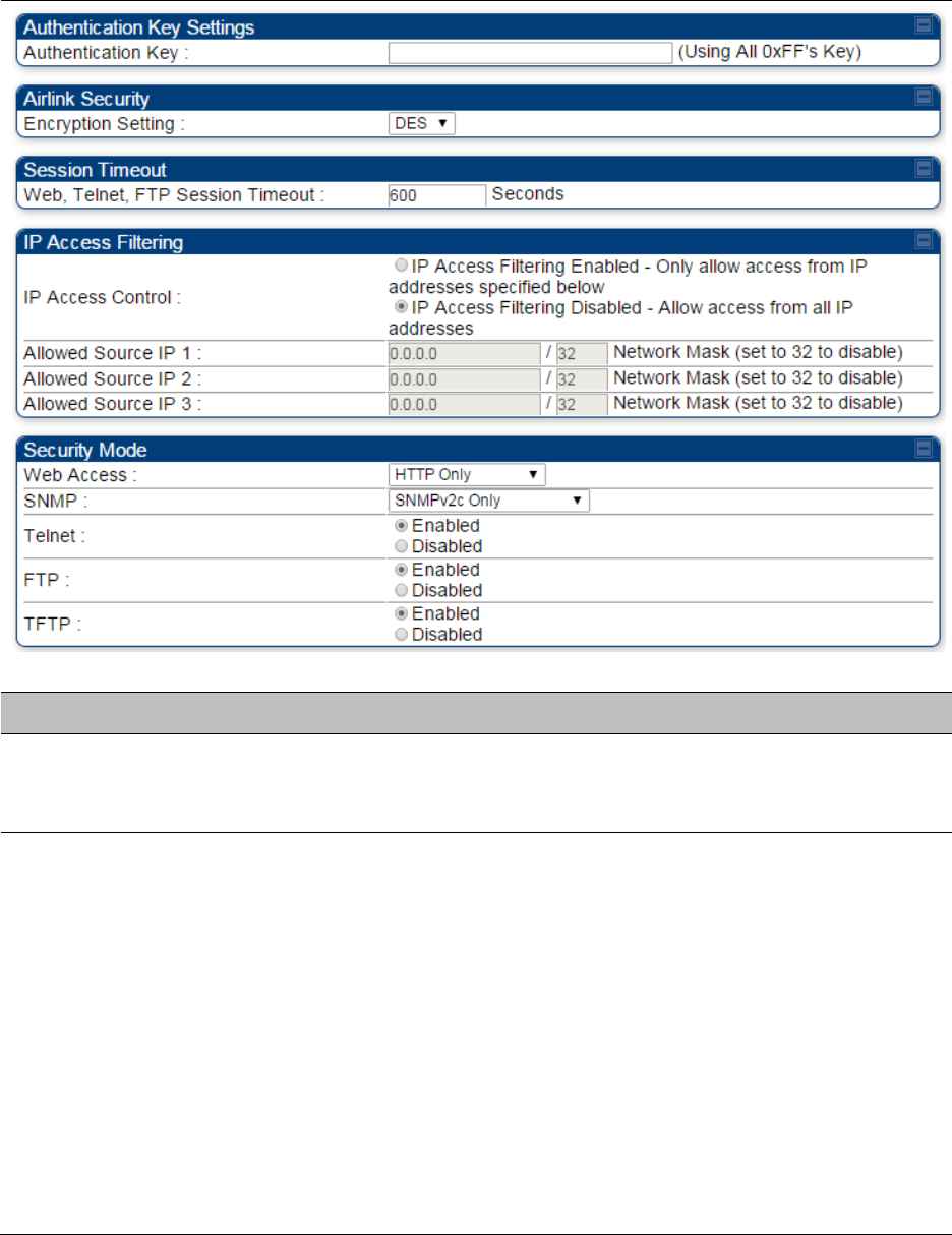
Chapter 7: Configuration
Configuring security
Page 7-190
Security page – PTP 450/450i BHS
The Security page of PTP 450/450i BHS is explained in Table 120.
Table 120 Security attributes for PTP 450/450i BHS
Attribute
Meaning
Authentication Key
Only if the BHM to which this BHS registers requires an authentication,
specify the key that the BHS will use when authenticating. For alpha
characters in this hex key, use only upper case.
Encryption Setting
Specify the type of airlink security to apply to this BHS. The encryption
setting must match the encryption setting of the BHM.
None provides no encryption on the air link.
DES (Data Encryption Standard): An over-the-air link encryption option
that uses secret 56-bit keys and 8 parity bits. DES performs a series of bit
permutations, substitutions, and recombination operations on blocks of
data. DES encryption does not affect the performance or throughput of
the system. It is factory default setting.
AES (Advanced Encryption Standard): An over-the-air link encryption
option that uses the Rijndael algorithm and 128-bit keys to establish a
higher level of security than DES. AES products are certified as
compliant with the Federal Information Processing Standards (FIPS 197)
in the U.S.A.

Chapter 7: Configuration
Configuring security
Page 7-191
Web, Telnet, FTP
Session Timeout
Enter the expiry in seconds for remote management sessions via HTTP,
telnet, or FTP access to the BHS.
IP Access Control
You can permit access to the BHS from any IP address (IP Access
Filtering Disabled) or limit it to access from only one, two, or three IP
addresses that you specify (IP Access Filtering Enabled). If you select IP
Access Filtering Enabled, then you must populate at least one of the
three Allowed Source IP parameters or have no access permitted from
any IP address
Allowed Source IP 1
to 3
If you selected IP Access Filtering Enabled for the IP Access Control
parameter, then you must populate at least one of the three Allowed
Source IP parameters or have no access permitted to the BHS from any
IP address. You may populate as many as all three.
If you selected IP Access Filtering Disabled for the IP Access Control
parameter, then no entries in this parameter are read, and access from
all IP addresses is permitted.
A subnet mask may be defined for each entry to allow for filtering
control based on a range of IP addresses.
Web Access
The Radio supports secured and non-secured web access protocols.
Select suitable web access from drop down list:
HTTP Only – provides non-secured web access. The radio to be
accessed via http://<IP of Radio>.
HTTPS Only – provides a secured web access. The radio to be
accessed via https://<IP of Radio>.
HTTP and HTTPS – If enabled, the radio can be accessed via both
http and https.
SNMP
This option allows to configure SNMP agent communication version. It
can be selected from drop down list :
SNMPv2c Only – Enables SNMP v2 community protocol.
SNMPv3 Only – Enables SNMP v3 protocol. It is secured
communication protocol.
SNMPv2c and SNMPv3 – It enables both the protocols.
Telnet
This option allows to Enable and Disable Telnet access to the Radio.
FTP
This option allows to Enable and Disable FTP access to the Radio.
TFTP
This option allows to Enable and Disable TFTP access to the Radio.

Chapter 7: Configuration
Configuring radio parameters
Page 7-192
Configuring radio parameters
PMP 450m – Configurating radio on page 7-193
PMP/PTP 450i – Configurating radio on page 7-193
PMP/PTP 450 – Configurating radio on page 7-217
Custom Frequencies page on page 7-234
DFS for 5 GHz Radios on page 7-237
MIMO-A mode of operation on page 7-239
Improved PPS performance of PMP 450 and 450i SMs on page 7-241
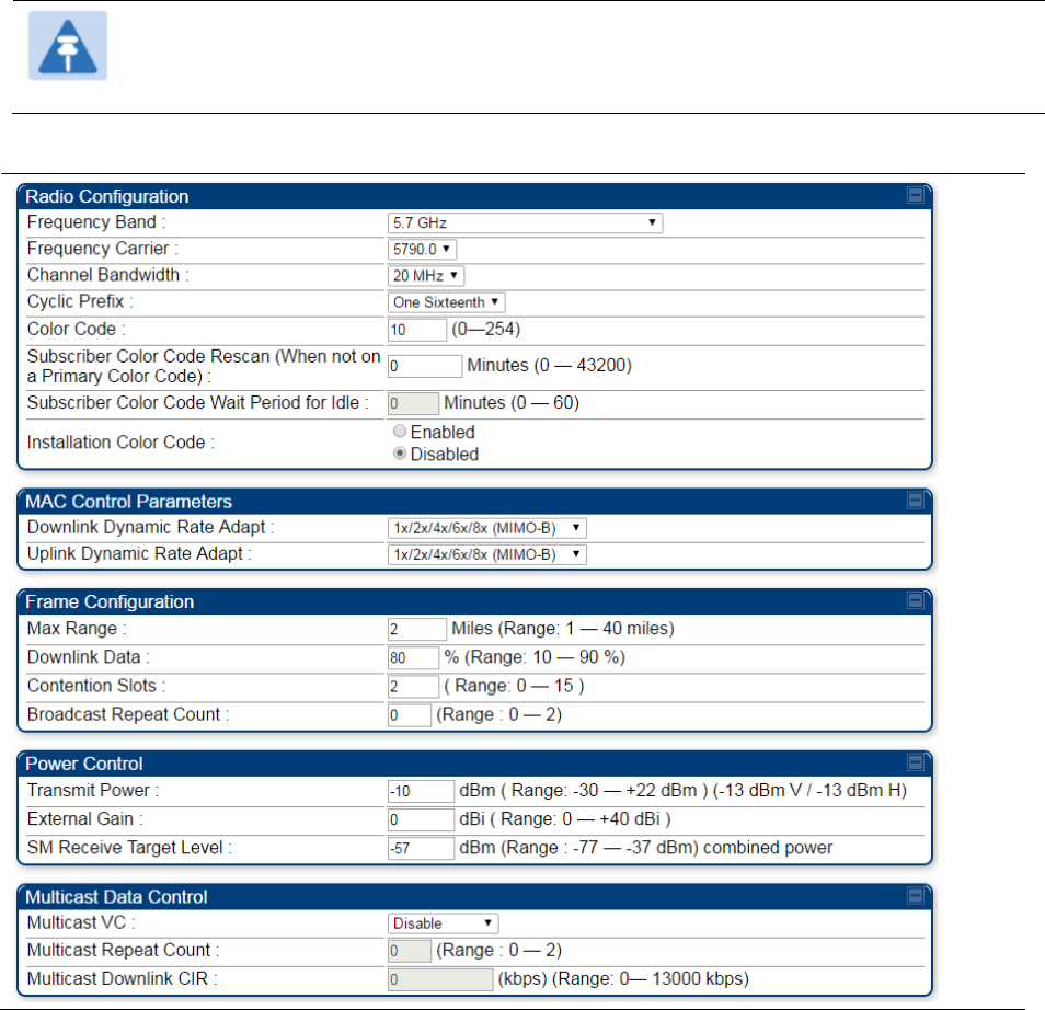
Chapter 7: Configuration
Configuring radio parameters
Page 7-193
PMP 450m – Configurating radio
Radio page - PMP 450m AP 5 GHz
The Radio tab of the PMP 450m AP contains some of the configurable parameters that define how
an AP operates.
Note
Only the frequencies available for your region and the selected Channel bandwidth are
displayed.
Table 121 PMP 450m AP Radio attributes - 5 GHz
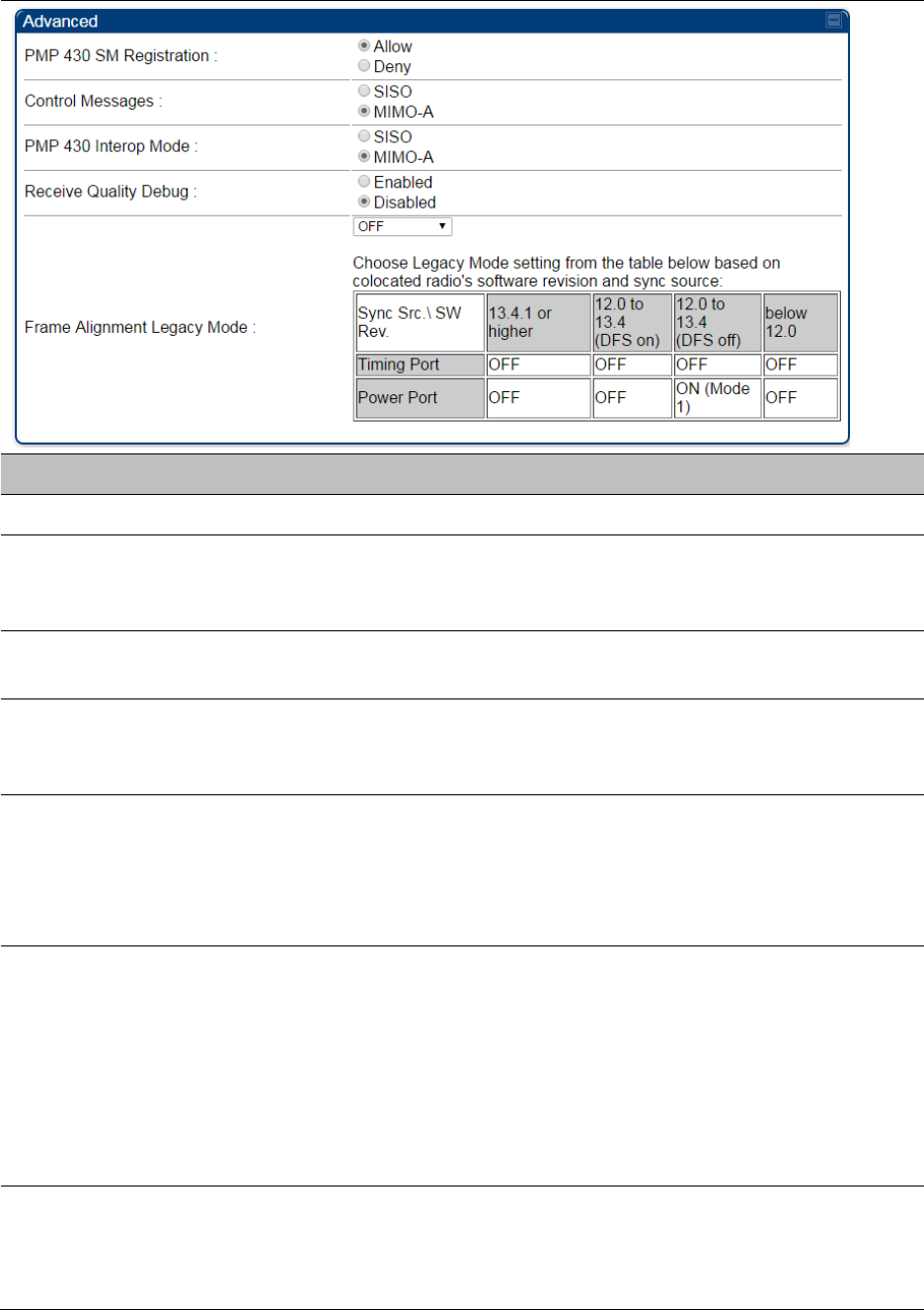
Chapter 7: Configuration
Configuring radio parameters
Page 7-194
Attribute
Meaning
Frequency Band
Select the desired operating frequency band.
Frequency Carrier
Specify the frequency for the module to transmit. The default for this
parameter is None. For a list of channels in the band, see the drop-down
list on the radio GUI.
Alternate Frequency
Carrier 1 and 2
These parameters are displayed based on Regional Settings. Refer
Country on page 7-142
Channel Bandwidth
The channel size used by the radio for RF transmission. The setting for
the channel bandwidth must match between the AP and the SM. The
supported Channel Bandwidths are 5, 10 and 20 MHz.
Cyclic Prefix
OFDM technology uses a cyclic prefix, where a portion of the end of a
symbol (slot) is repeated at the beginning of the symbol to allow multi-
pathing to settle before receiving the desired data. A 1/16 cyclic prefix
means that for every 16 bits of throughput data transmitted, an
additional bit is used.
Color Code
Specify a value from 0 to 254. For registration to occur, the color code of
the SM and the AP must match. Color code is not a security feature.
Instead, color code is a management feature, typically for assigning each
sector a different color code.
Color code allows you to force a SM to register to only a specific AP,
even where the SM can communicate with multiple APs. The default
setting for the color code value is 0. This value matches only the color
code of 0 (not all 255 color codes).
Subscriber Color
Code Rescan (When
not on a Primary
Color Code)
This timer may be utilized to initiate SM rescans in order to register to an
AP configured with the SM‘s primary color code.

Chapter 7: Configuration
Configuring radio parameters
Page 7-195
The time (in minutes) for a subscriber to rescan (if this AP is not
configured with the SM‘s primary color code). This timer will only fire
once – if the Subscriber Color Code Wait Period for Idle timer is
configured with a nonzero value and the Subscriber Color Code Rescan
expires, the Subscriber Color Code Wait Period for Idle is started. If the
Subscriber Color Code Wait Period for Idle timer is configured with a
zero value and the Subscriber Color Code Rescan timer expires, the SM
will immediately go into rescan mode
Subscriber Color
Code Wait Period for
Idle
The time (in minutes) for a subscriber to rescan while idle (if this AP is
not configured with the SM’s primary color code). This timer will fire
periodic events. The fired event determines if any RF unicast traffic
(either inbound or outbound) has occurred since the last event. If the
results of the event determine that no RF unicast traffic has occurred
(SM is idle), then the subscriber will rescan.
Installation Color
Code
With this feature enabled on the AP and SM, operators may install and
remotely configure SMs without having to configure matching color
codes between the modules. While the SM is accessible for
configuration from above the AP (for remote provisioning) and below
the SM (for local site provisioning), no user data is passed over the radio
link. When using the Installation Color Code feature, ensure that the SM
is configured with the factory default Color Code configuration (Color
Code 1 is “0”, Color Code 2-10 set to “0” and “Disable”). The status of
the Installation Color Code can be viewed on the AP Eval web GUI page,
and when the SM is registered using the Installation Color Code the
message “SM is registered via ICC – Bridging Disabled!” is displayed in
red on every SM GUI page. The Installation Color Code parameter is
configurable without a radio reboot for both the AP and SM. If a SM is
registered via Installation Color Code and the feature is then disabled,
operators will need to reboot the SM or force it to reregister (i.e. using
Rescan APs functionality on the AP Eval page).
Max Range
Enter a number of miles (or kilometers divided by 1.61, then rounded to
an integer) for the furthest distance from which a SM is allowed to
register to this AP. Do not set the distance to any greater number of
miles. A greater distance
does not increase the power of transmission from the AP.
can reduce aggregate throughput.
Regardless of this distance, the SM must meet the minimum
requirements for an acceptable link. If the AP is in cluster, then you must
set this parameter on all other APs in the cluster exactly the same,
except as described in the NOTE admonition below. The default value of
this parameter is 2 miles (3.2 km).

Chapter 7: Configuration
Configuring radio parameters
Page 7-196
Downlink Data
Specify the percentage of the aggregate throughput for the downlink
(frames transmitted from the AP to the subscriber). For example, if the
aggregate (uplink and downlink total) throughput on the AP is 90 Mb,
then 75% specified for this parameter allocates 67.5 Mb for the downlink
and 22.5 Mb for the uplink. The default for this parameter is 75%. This
parameter must be set in the range of 15% - 85%, otherwise the invalid
input will not be accepted and the previously-entered valid setting is
used.
Note
This setting does not prevent a device connected to the
Ethernet port from accessing the management interface of
other SMs in the network. To prevent this, use the IP Access
Filtering Enabled selection in the IP Access Control
parameter of the SMs in the network. See IP Access Control
below.
Contention Slots
(a.k.a. Control Slots)
This field indicates the number of (reserved) Contention slots configured
by the operator. The SM uses reserved Contention slots and unused data
slots for bandwidth requests. See Contention slots on page7-238.
Broadcast Repeat
Count
The default is 2 repeats (in addition to the original broadcast packet, for
a total of 3 packets sent for every one needed), and is settable to 1 or 0
repeats (2 or 1 packets for every broadcast).
ARQ (Automatic Repeat reQuest) is not present in downlink broadcast
packets, since it can cause unnecessary uplink traffic from every SM for
each broadcast packet. For successful transport without ARQ, the AP
repeats downlink broadcast packets. The SMs filter out all repeated
broadcast packets and, thus, do not transport further.
The default of 2 repeats is optimum for typical uses of the network as an
internet access system. In applications with heavy download broadcast
such as video distribution, overall throughput is significantly improved
by setting the repeat count to 1 or 0. This avoids flooding the downlink
with repeat broadcast packets.
Transmitter Output
Power
This value represents the combined power of the AP’s two transmitters.
Nations and regions may regulate transmitter output power. For
example
900 MHz, 5.4 GHz and 5.8 GHz modules are available as
connectorized radios, which require the operator to adjust power to
ensure regulatory compliance.
The professional installer of the equipment has the responsibility to
maintain awareness of applicable regulations.
calculate the permissible transmitter output power for the module.
confirm that the initial power setting is compliant with national or
regional regulations.

Chapter 7: Configuration
Configuring radio parameters
Page 7-197
confirm that the power setting is compliant following any reset of
the module to factory defaults.
External Gain
This value needs to correspond to the published gain of the antenna
used to ensure the radio will meet regulatory requirements.
SM Receive Target
Level
Each SM’s Transmitter Output Power is automatically set by the AP. The
AP monitors the received power from each SM, and adjusts each SM’s
Transmitter Output Power so that the received power at the AP from that
SM is not greater what is set in this field. This value represents the
transmitted and received power (combined power) perceived on the SM.
Multicast VC Data
Rate
This pull down menu of the Multicast Data Control screen helps in
configuring multicast packets to be transmitted over a dedicated channel
at a configurable rate of 1X, 2X, 4X or 6X. The default value is “Disable”.
If set to the default value, all multicast packets are transmitted over the
Broadcast VC data path. This feature is available only for the PMP 450
and is not backward compatible with PMP 430 series of radios.
Multicast Repeat
Count
This value is the number of packets that are repeated for every multicast
VC packet received on the AP (located under Radio tab of Configuration).
Multicast (like Broadcast) packets go over a VC that is shared by all SMs,
so there is no guaranteed delivery. The repeat count is an attempt to
improve the odds of the packets getting over the link. If the user has
issues with packets getting dropped, they can use this parameter to
improve the performance at the cost of the overall throughput possible
on that channel. The default value is 0.
Multicast Downlink
CIR
This value is the committed information rate for the multicast downlink
VC (located under the Radio tab of Configuration). The default value is 0
kbps. The range of this parameter is based on the number of repeat
counts. The higher the repeat count, the lower the range for the
multicast downlink CIR.
SM Registration All
This field allows to control registration of all type 450 platform SM
(450i/450/430) or 450i Series SM only.
PMP 430 SM
Registration
This field allows to control of PMP 430 SMs whether PMP 430 SMs are
allowed to register to PMP 450 APs. By default, it is enabled and PMP
430 SM registrations are accepted.
When this field is set to disabled, PMP 430 SM’s registrations fail with
reject reason 8. This will cause SMs to lock out the AP for 15 minutes.
Note
This option is not displayed if the Frame Period is set to
5 ms. This option applies only to PMP 450 5 GHz APs.
Control Message
Controls whether the control messages are sent in MIMO-B or MIMO-
A mode. MIMO-A is recommended. However, if an AP on 13.2 is
attempting to connect to an SM on 13.1.3 or before, changing to
MIMO-B may aid in getting the SM registered.
Chapter 7: Configuration
Configuring radio parameters
Page 7-198
PMP 450/430 Legacy
mode
Disabled: It is factory default setting. It allows to operate in 450i platform
capabilities.
Enabled: It allows to operate radio in Legacy mode PMP 450 or 430.
PMP 430 Interop
Mode
For n-1 compatibility, In SISO mode this forces the AP to only send
Control and Beacons over one of the RF paths.
Receive Quality
Debug
To aid in link performance monitoring, the AP and SM now report the
number of fragments received per modulation (i.e. QPSK, 16-QAM, 64-
QAM) and per channel (polarization).
Note
Due to CPU load, this will slightly degrade packet per second
processing.
Frame Alignment
Legacy Mode
Mode
Behavior (non-900 MHz
radios)
Behavior (FSK 900 MHz
radios)
OFF
By default frame start is
aligned with devices
with Timing Port
synchronization
If the synchronization
source changes (due to
Autosync or otherwise)
the radio will
dynamically adjust its
frame start to maintain
alignment with the
default frame start
timing
By default frame start is
aligned with FSK 900
MHz devices with
Timing Port
synchronization
If the synchronization
source changes (due to
Autosync or otherwise)
the radio will
dynamically adjust its
frame start to maintain
alignment with the
default frame start
timing
ON
(Mode 1)
The radio will align with
devices running
software versions from
12.0 to 13.4.
The radio will align with
FSK 900 MHz devices
running software
versions from 12.0 to
13.4.
ON
(Mode 2)
N/A
The radio will align with
FSK 900 MHz devices
with software versions
11.2 or older.
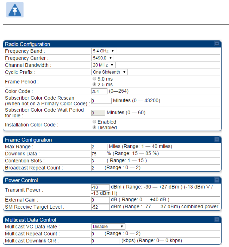
Chapter 7: Configuration
Configuring radio parameters
Page 7-199
PMP/PTP 450i – Configurating radio
Radio page - PMP 450i AP 5 GHz
The Radio tab of the PMP 450i AP contains some of the configurable parameters that define how
an AP operates.
Note
Only the frequencies available for your region and the selected Channel bandwidth
(5/10/20) are displayed.
Table 122 PMP 450i AP Radio attributes - 5 GHz
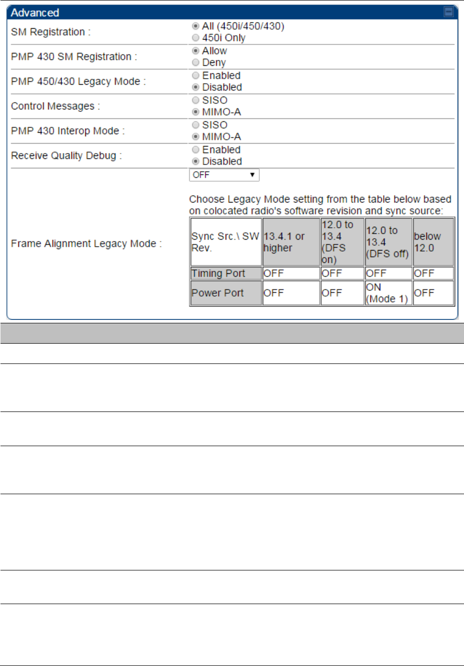
Chapter 7: Configuration
Configuring radio parameters
Page 7-200
Attribute
Meaning
Frequency Band
Select the desired operating frequency band.
Frequency Carrier
Specify the frequency for the module to transmit. The default for this
parameter is None. For a list of channels in the band, see the drop-down
list on the radio GUI.
Alternate Frequency
Carrier 1 and 2
These parameters are displayed based on Regional Settings. Refer
Country on page 7-142
Channel Bandwidth
The channel size used by the radio for RF transmission. The setting for
the channel bandwidth must match between the AP and the SM. The
supported Channel Bandwidths are 5, 10 and 20 MHz.
Cyclic Prefix
OFDM technology uses a cyclic prefix, where a portion of the end of a
symbol (slot) is repeated at the beginning of the symbol to allow multi-
pathing to settle before receiving the desired data. A 1/16 cyclic prefix
means that for every 16 bits of throughput data transmitted, an
additional bit is used.
Frame Period
Select the Frame Period in of the radio. The support Frame Periods are 5
ms and 2.5 ms.
Color Code
Specify a value from 0 to 254. For registration to occur, the color code of
the SM and the AP must match. Color code is not a security feature.
Instead, color code is a management feature, typically for assigning each
sector a different color code.

Chapter 7: Configuration
Configuring radio parameters
Page 7-201
Color code allows you to force a SM to register to only a specific AP,
even where the SM can communicate with multiple APs. The default
setting for the color code value is 0. This value matches only the color
code of 0 (not all 255 color codes).
Subscriber Color
Code Rescan (When
not on a Primary
Color Code)
This timer may be utilized to initiate SM rescans in order to register to an
AP configured with the SM‘s primary color code.
The time (in minutes) for a subscriber to rescan (if this AP is not
configured with the SM‘s primary color code). This timer will only fire
once – if the Subscriber Color Code Wait Period for Idle timer is
configured with a nonzero value and the Subscriber Color Code Rescan
expires, the Subscriber Color Code Wait Period for Idle is started. If the
Subscriber Color Code Wait Period for Idle timer is configured with a
zero value and the Subscriber Color Code Rescan timer expires, the SM
will immediately go into rescan mode
Subscriber Color
Code Wait Period for
Idle
The time (in minutes) for a subscriber to rescan while idle (if this AP is
not configured with the SM’s primary color code). This timer will fire
periodic events. The fired event determines if any RF unicast traffic
(either inbound or outbound) has occurred since the last event. If the
results of the event determine that no RF unicast traffic has occurred
(SM is idle), then the subscriber will rescan.
Installation Color
Code
With this feature enabled on the AP and SM, operators may install and
remotely configure SMs without having to configure matching color
codes between the modules. While the SM is accessible for
configuration from above the AP (for remote provisioning) and below
the SM (for local site provisioning), no user data is passed over the radio
link. When using the Installation Color Code feature, ensure that the SM
is configured with the factory default Color Code configuration (Color
Code 1 is “0”, Color Code 2-10 set to “0” and “Disable”). The status of
the Installation Color Code can be viewed on the AP Eval web GUI page,
and when the SM is registered using the Installation Color Code the
message “SM is registered via ICC – Bridging Disabled!” is displayed in
red on every SM GUI page. The Installation Color Code parameter is
configurable without a radio reboot for both the AP and SM. If a SM is
registered via Installation Color Code and the feature is then disabled,
operators will need to reboot the SM or force it to reregister (i.e. using
Rescan APs functionality on the AP Eval page).
Max Range
Enter a number of miles (or kilometers divided by 1.61, then rounded to
an integer) for the furthest distance from which a SM is allowed to
register to this AP. Do not set the distance to any greater number of
miles. A greater distance
does not increase the power of transmission from the AP.
can reduce aggregate throughput.
Chapter 7: Configuration
Configuring radio parameters
Page 7-202
Regardless of this distance, the SM must meet the minimum
requirements for an acceptable link. If the AP is in cluster, then you must
set this parameter on all other APs in the cluster exactly the same,
except as described in the NOTE admonition below. The default value of
this parameter is 2 miles (3.2 km).
Downlink Data
Specify the percentage of the aggregate throughput for the downlink
(frames transmitted from the AP to the subscriber). For example, if the
aggregate (uplink and downlink total) throughput on the AP is 90 Mb,
then 75% specified for this parameter allocates 67.5 Mb for the downlink
and 22.5 Mb for the uplink. The default for this parameter is 75%. This
parameter must be set in the range of 15% - 85%, otherwise the invalid
input will not be accepted and the previously-entered valid setting is
used.
Note
This setting does not prevent a device connected to the
Ethernet port from accessing the management interface of
other SMs in the network. To prevent this, use the IP Access
Filtering Enabled selection in the IP Access Control
parameter of the SMs in the network. See IP Access Control
below.
Contention Slots
(a.k.a. Control Slots)
This field indicates the number of (reserved) Contention slots configured
by the operator. The SM uses reserved Contention slots and unused data
slots for bandwidth requests. See Contention slots on page7-238.
Broadcast Repeat
Count
The default is 2 repeats (in addition to the original broadcast packet, for
a total of 3 packets sent for every one needed), and is settable to 1 or 0
repeats (2 or 1 packets for every broadcast).
ARQ (Automatic Repeat reQuest) is not present in downlink broadcast
packets, since it can cause unnecessary uplink traffic from every SM for
each broadcast packet. For successful transport without ARQ, the AP
repeats downlink broadcast packets. The SMs filter out all repeated
broadcast packets and, thus, do not transport further.
The default of 2 repeats is optimum for typical uses of the network as an
internet access system. In applications with heavy download broadcast
such as video distribution, overall throughput is significantly improved
by setting the repeat count to 1 or 0. This avoids flooding the downlink
with repeat broadcast packets.
Transmitter Output
Power
This value represents the combined power of the AP’s two transmitters.
Nations and regions may regulate transmitter output power. For
example
900 MHz, 5.4 GHz and 5.8 GHz modules are available as
connectorized radios, which require the operator to adjust power to
ensure regulatory compliance.
The professional installer of the equipment has the responsibility to
maintain awareness of applicable regulations.

Chapter 7: Configuration
Configuring radio parameters
Page 7-203
calculate the permissible transmitter output power for the module.
confirm that the initial power setting is compliant with national or
regional regulations.
confirm that the power setting is compliant following any reset of
the module to factory defaults.
External Gain
This value needs to correspond to the published gain of the antenna
used to ensure the radio will meet regulatory requirements.
SM Receive Target
Level
Each SM’s Transmitter Output Power is automatically set by the AP. The
AP monitors the received power from each SM, and adjusts each SM’s
Transmitter Output Power so that the received power at the AP from that
SM is not greater what is set in this field. This value represents the
transmitted and received power (combined power) perceived on the SM.
Multicast VC Data
Rate
This pull down menu of the Multicast Data Control screen helps in
configuring multicast packets to be transmitted over a dedicated channel
at a configurable rate of 1X, 2X, 4X or 6X. The default value is “Disable”.
If set to the default value, all multicast packets are transmitted over the
Broadcast VC data path. This feature is available only for the PMP 450
and is not backward compatible with PMP 430 series of radios.
Multicast Repeat
Count
This value is the number of packets that are repeated for every multicast
VC packet received on the AP (located under Radio tab of Configuration).
Multicast (like Broadcast) packets go over a VC that is shared by all SMs,
so there is no guaranteed delivery. The repeat count is an attempt to
improve the odds of the packets getting over the link. If the user has
issues with packets getting dropped, they can use this parameter to
improve the performance at the cost of the overall throughput possible
on that channel. The default value is 0.
Multicast Downlink
CIR
This value is the committed information rate for the multicast downlink
VC (located under the Radio tab of Configuration). The default value is 0
kbps. The range of this parameter is based on the number of repeat
counts. The higher the repeat count, the lower the range for the
multicast downlink CIR.
Chapter 7: Configuration
Configuring radio parameters
Page 7-204
SM Registration All
This field allows to control registration of all type 450 platform SM
(450i/450/430) or 450i Series SM only.
PMP 430 SM
Registration
This field allows to control of PMP 430 SMs whether PMP 430 SMs are
allowed to register to PMP 450 APs. By default, it is enabled and PMP
430 SM registrations are accepted.
When this field is set to disabled, PMP 430 SM’s registrations fail with
reject reason 8. This will cause SMs to lock out the AP for 15 minutes.
Note
This option is not displayed if the Frame Period is set to
5 ms. This option applies only to PMP 450 5 GHz APs.
Control Message
Controls whether the control messages are sent in MIMO-B or MIMO-
A mode. MIMO-A is recommended. However, if an AP on 13.2 is
attempting to connect to an SM on 13.1.3 or before, changing to
MIMO-B may aid in getting the SM registered.
PMP 450/430 Legacy
mode
Disabled: It is factory default setting. It allows to operate in 450i platform
capabilities.
Enabled: It allows to operate radio in Legacy mode PMP 450 or 430.
PMP 430 Interop
Mode
For n-1 compatibility, In SISO mode this forces the AP to only send
Control and Beacons over one of the RF paths.
Receive Quality
Debug
To aid in link performance monitoring, the AP and SM now report the
number of fragments received per modulation (i.e. QPSK, 16-QAM, 64-
QAM) and per channel (polarization).
Note
Due to CPU load, this will slightly degrade packet per second
processing.
Frame Alignment
Legacy Mode
Mode
Behavior (non-900 MHz
radios)
Behavior (FSK 900 MHz
radios)
OFF
By default frame start is
aligned with devices
with Timing Port
synchronization
If the synchronization
source changes (due to
Autosync or otherwise)
the radio will
dynamically adjust its
frame start to maintain
alignment with the
By default frame start is
aligned with FSK 900
MHz devices with
Timing Port
synchronization
If the synchronization
source changes (due to
Autosync or otherwise)
the radio will
dynamically adjust its
frame start to maintain
alignment with the

Chapter 7: Configuration
Configuring radio parameters
Page 7-205
default frame start
timing
default frame start
timing
ON
(Mode 1)
The radio will align with
devices running
software versions from
12.0 to 13.4.
The radio will align with
FSK 900 MHz devices
running software
versions from 12.0 to
13.4.
ON
(Mode 2)
N/A
The radio will align with
FSK 900 MHz devices
with software versions
11.2 or older.
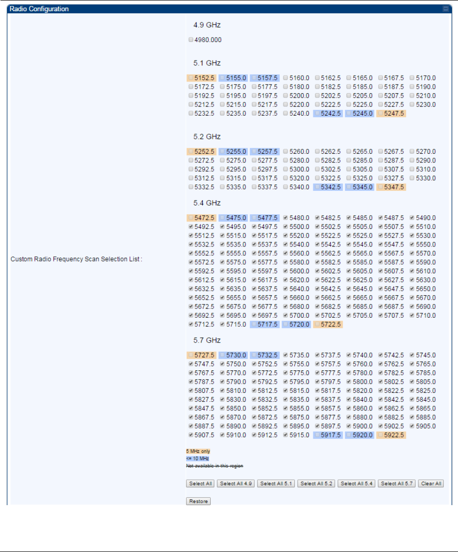
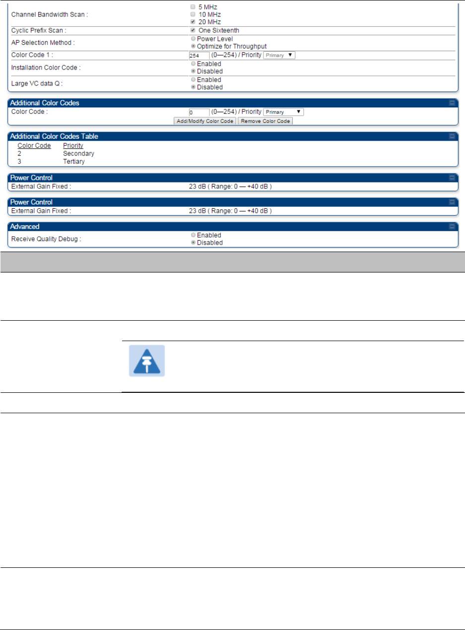
Chapter 7: Configuration
Configuring radio parameters
Page 7-207
Attribute
Meaning
Custom Radio
Frequency Scan
Selection List
Check the frequencies that SM has to scan for AP transmissions. See
Radio Frequency Scan Selection List on page 7-231.
Channel Bandwidth
Scan
The channel size used by the radio for RF transmission.
Note
Selecting multiple channel bandwidths will increase
registration and re-registration times.
Cyclic Prefix Scan
The cyclic prefix for which AP scanning is executed.
AP Selection Method
Operators may configure the method by which a scanning SM selects an
AP. By default, AP Selection Method is set to “Optimize for Throughput”,
which has been the mode of operation in releases prior to 12.0.3.1.
Power Level: AP selection based solely on power level
or
Optimize for Throughput: AP selection based on throughput optimization
– the selection decision is based on power level (which affects the
modulation state), channel bandwidth (which affects throughput) and
number of SM registrations to the AP (which affects system contention
performance).
Color Code 1
Color code allows you to force the SM to register to only a specific AP,
even where the SM can communicate with multiple APs. For registration
to occur, the color code of the SM and the AP must match. Specify a
value from 0 to 254.

Chapter 7: Configuration
Configuring radio parameters
Page 7-208
Color code is not a security feature. Instead, color code is a management
feature, typically for assigning each sector a different color code.
The default setting for the color code value is 0. This value matches only
the color code of 0 (not all 255 color codes).
SMs may be configured with up to 20 color codes. These color codes can
be tagged as Primary, Secondary, or Tertiary, or Disable. When the SM
is scanning for APs, it will first attempt to register to an AP that matches
one of the SM’s primary color codes. Failing that, the SM will continue
scanning and attempt to register to an AP that matches one of the SM’s
secondary color codes. Failing that, the SM will continue scanning and
attempt to register to an AP that matches one of the SM’s tertiary color
codes. This is all done in the scanning mode of the SM and will repeat
until a registration has occurred.
Color codes in the same priority group are treated equally. For example,
all APs matching one of the SM’s primary color codes are analyzed
equally. Likewise, this evaluation is done for the secondary and tertiary
groups in order. The analysis for selecting an AP within a priority group
is based on various inputs, including signal strength and number of SMs
already registered to each AP.
The first color code in the configuration is the pre-Release 9.5 color code.
Thus, it is always a primary color code for legacy reasons.
The color codes can be disabled, with the exception of the first color
code.
Installation Color
Code
With this feature enabled on the AP and SM, operators may install and
remotely configure SMs without having to configure matching color
codes between the modules. When using the Installation Color Code
feature, ensure that the SM is configured with the factory default Color
Code configuration (Color Code 1 is “0”, Color Code 2-10 set to “0” and
“Disable”). The status of the Installation Color Code can be viewed on
the AP Eval web GUI page, and when the SM is registered using the
Installation Color Code the message “SM is registered via ICC – Bridging
Disabled!” is displayed in red on every SM GUI page. The Installation
Color Code parameter is configurable without a radio reboot for both the
AP and SM.
External Gain
This value represents the antenna gain.
For ODUs with integrated antenna, this is set at te correct value in the
factory.
For Connectorized ODUs with external antenna, the user must set this
value to the overall antenna gain, including any RF cable loss between
the ODU and the antenna.
Large VC data Queue
AP and BH have a configurable option used to prevent packet loss in the
uplink due to bursting IP traffic. This is designed for IP burst traffic
particular to video surveillance applications.

Chapter 7: Configuration
Configuring radio parameters
Page 7-209
Receive Quality
Debug
To aid in link performance monitoring, the AP and SM now report the
number of fragments received per modulation (i.e. QPSK, 16-QAM, 64-
QAM) and per channel (polarization).
Note
Due to CPU load, this will slightly degrade packet per
second processing.
Note
The frequencies that a user can select are controlled by the country or a region and the
Channel Bandwidth selected. There can be a case where a user adds a custom
frequency (from the Custom Frequencies page on page 7-234) and cannot see it in the
pull down menu.
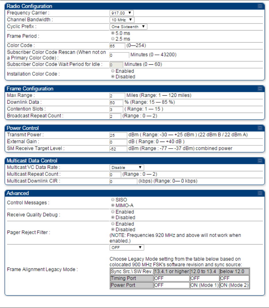

Chapter 7: Configuration
Configuring radio parameters
Page 7-211
Attribute
Meaning
Frequency Carrier
Specify the frequency for the module to transmit. The default for this
parameter is None. For a list of channels in the band, see the drop-
down list on the radio GUI.
Channel Bandwidth
The channel size used by the radio for RF transmission. The setting
for the channel bandwidth must match between the AP and the SM.
The supported Channel Bandwidths are 5, 7, 10 and 20 MHz.
Cyclic Prefix
See Table 122 PMP 450i AP Radio attributes - 5 GHz on page 7-199.
Frame Period
Color Code
Subscriber Color Code
Rescan (When not on a
Primary Color Code)
Subscriber Color Code
Wait Period for Idle
Installation Color Code
Max Range
See Table 122 PMP 450i AP Radio attributes - 5 GHz on page 7-199.
Downlink Data
Contention Slots
(a.k.a. Control Slots)
Broadcast Repeat Count
Transmitter Output
Power
See Table 122 PMP 450i AP Radio attributes - 5 GHz on page 7-199.
External Gain
SM Receive Target Level
Multicast VC Data Rate
See Table 122 PMP 450i AP Radio attributes - 5 GHz on page 7-199.
Multicast Repeat Count
Multicast Downlink CIR
Control Message
Receive Quality Debug
Pager Reject Filter
In 900 MHz, Pager Reject filter is placed on the AP to block Pager
signals which could cause interference to the whole band. The Pager
signals typically operate in the 928-930 frequency range. When the
filter is enabled, the signals of 920 MHz and above are attenuated
which enables better reception of signals in the rest of the band. Note
that the AP/SM should not be configured on the frequencies of 920
MHz and above when this filter is enabled.
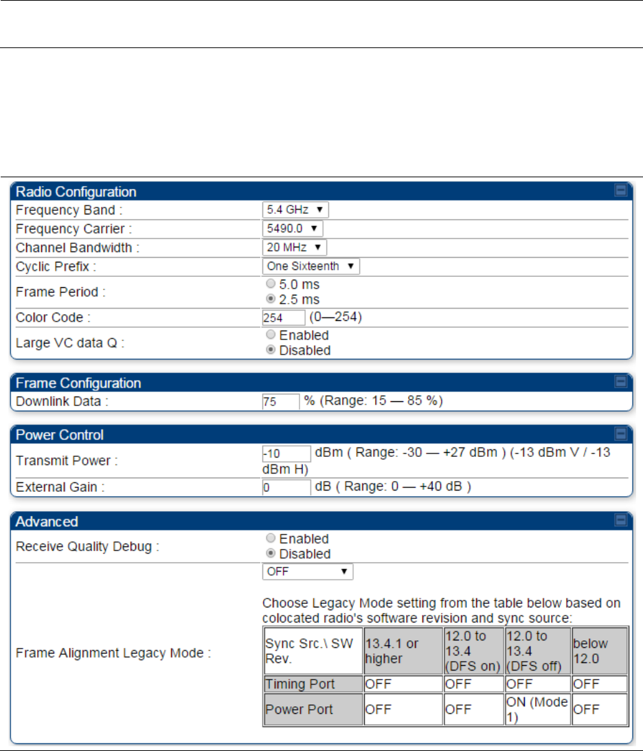
Chapter 7: Configuration
Configuring radio parameters
Page 7-212
Frame Alignment
Legacy Mode
See Table 122 PMP 450i AP Radio attributes - 5 GHz on page 7-199.
Radio page - PTP 450i BHM 5 GHz
The Radio page of PTP 450i BHM is explained in Table 125.
Table 125 PTP 450i BHM Radio page attributes – 5 GHz
Chapter 7: Configuration
Configuring radio parameters
Page 7-213
Attribute
Meaning
Frequency Band
Select the operating frequency band of the radio. The supported bands
are 4.9 GHz, 5.4 GHz and 5.7 GHz.
Frequency Carrier
Specify the frequency for the module to transmit. The default for this
parameter is None. For a list of channels in the band, see the drop-down
list on the radio GUI.
Channel Bandwidth
The channel size used by the radio for RF transmission. The setting for
the channel bandwidth must match between the BHM and the BHS.
Cyclic Prefix
OFDM technology uses a cyclic prefix, where a portion of the end of a
symbol (slot) is repeated at the beginning of the symbol to allow multi-
pathing to settle before receiving the desired data. A 1/16 cyclic prefix
means that for every 16 bits of throughput data transmitted, an
additional bit is used.
Frame Period
Select the Frame Period of the radio. The support Frame Periods are : 5
ms and 2.5 ms.
Color Code
Specify a value from 0 to 254. For registration to occur, the color code of
the BHM and the BHS must match. Color code is not a security feature.
Instead, color code is a management feature, typically for assigning each
link a different color code.
Color code allows you to force a BHS to register to only a specific BHM.
The default setting for the color code value is 0. This value matches
only the color code of 0 (not all 255 color codes).
Large VC data Q
Enable Large VC Q for applications that burst data high rates. Large Qs
may decrease effective throughput for TCP application.
Disable Large VC Q if application need not handle bursts of data. Large
Qs may decrease effective throughput for TCP application.
Downlink Data
Specify the percentage of the aggregate throughput for the downlink
(frames transmitted from the BHM to the subscriber). For example, if the
aggregate (uplink and downlink total) throughput on the BHM is 132
Mbps, then 75% specified for this parameter allocates 99 Mbps for the
downlink and 33 Mbps for the uplink. The default for this parameter is
50%. This parameter must be set in the range of 15% - 85%, otherwise
the invalid input will not be accepted and the previously-entered valid
setting is used.
Note
In order to prevent self-interference, the frame
configuration needs to align. This includes Downlink Data,
Max Range and Contention slots.
Transmit Power
This value represents the combined power of the BHM’s two
transmitters.
Nations and regions may regulate transmit power. For example

Chapter 7: Configuration
Configuring radio parameters
Page 7-214
PTP 450i modules are available as connectorized radios, which
require the operator to adjust power to ensure regulatory
compliance.
The professional installer of the equipment has the responsibility to:
Maintain awareness of applicable regulations.
Calculate the permissible transmitter output power for the module.
Confirm that the initial power setting is compliant with national or
regional regulations.
Confirm that the power setting is compliant following any reset of the
module to factory defaults.
External Gain
This value needs to correspond to the published gain of the antenna
used to ensure the radio will meet regulatory requirements.
Receive Quality
Debug
To aid in link performance monitoring, the BHM and BHS now report the
number of fragments received per modulation (i.e. QPSK, 16-QAM, 64-
QAM, 256-QAM) and per channel (polarization).
Note
Due to CPU load, this slightly degrades the packet during
per second processing.
Frame Alignment
Legacy Mode
See Table 122 PMP 450i AP Radio attributes - 5 GHz on page 7-199.
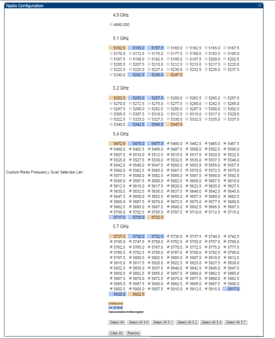
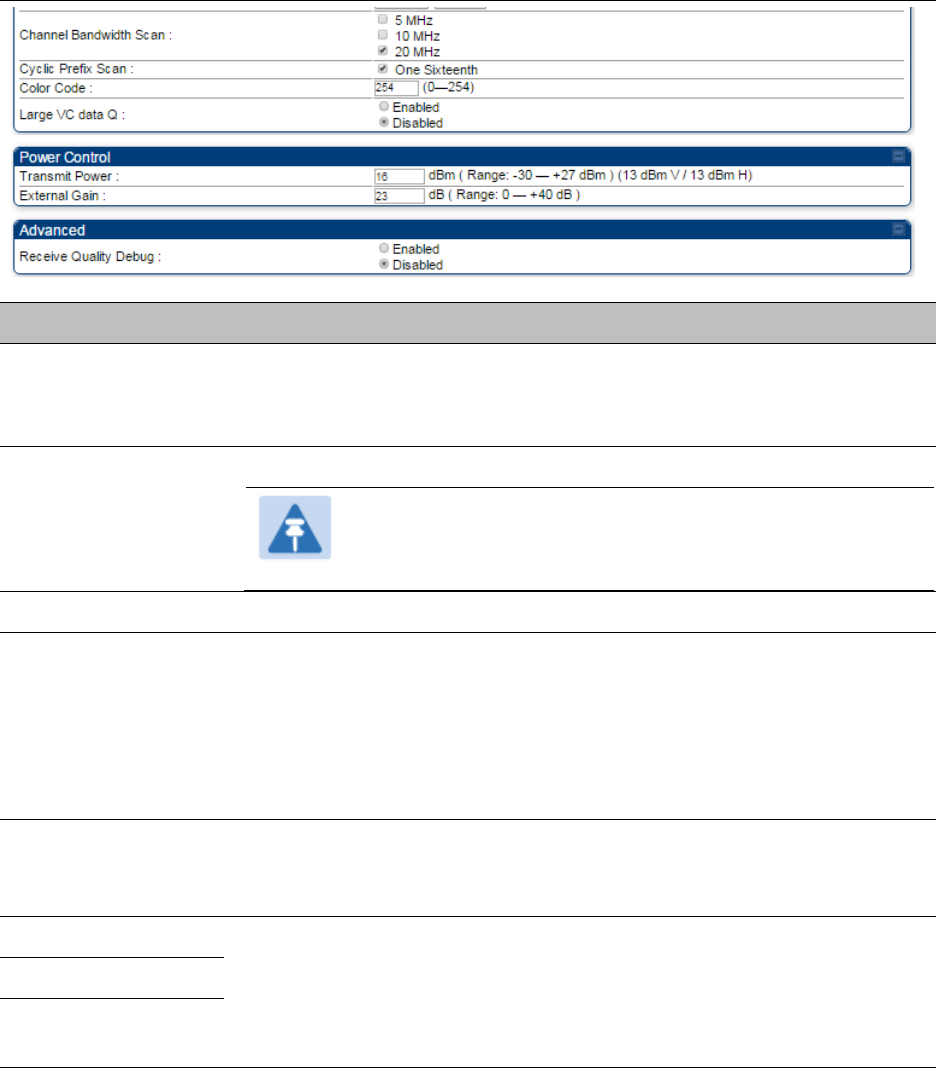
Chapter 7: Configuration
Configuring radio parameters
Page 7-216
Attribute
Meaning
Custom Radio
Frequency Scan
Selection List
Check any frequency that you want the BHS to scan for BHM
transmissions. See Radio Frequency Scan Selection List on page 7-231.
Channel Bandwidth
Scan
The channel size used by the radio for RF transmission.
Note
Selecting multiple channel bandwidths will increase
registration and re-registration times.
Cyclic Prefix Scan
The cyclic prefix for which BHM scanning is executed.
Color Code
Color code allows to force the BHS to register to only a specific BHM,
even where the BHS can communicate with multiple BHMs. For
registration to occur, the color code of the BHS and the BHM must
match. Specify a value from 0 to 254.
The color codes can be disabled, with the exception of the first color
code.
Large VC data Q
BHM and BHS have a configurable option used to prevent packet loss in
the uplink due to bursting IP traffic. This is designed for IP burst traffic
particular to video surveillance applications.
Transmit Power
Refer Table 125 PTP 450i BHM Radio page attributes – 5 GHz on page 7-
212
External Gain
Receive Quality
Debug
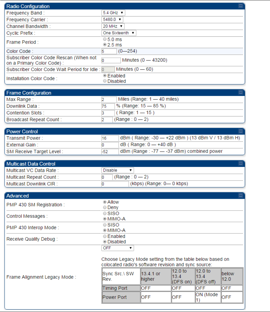
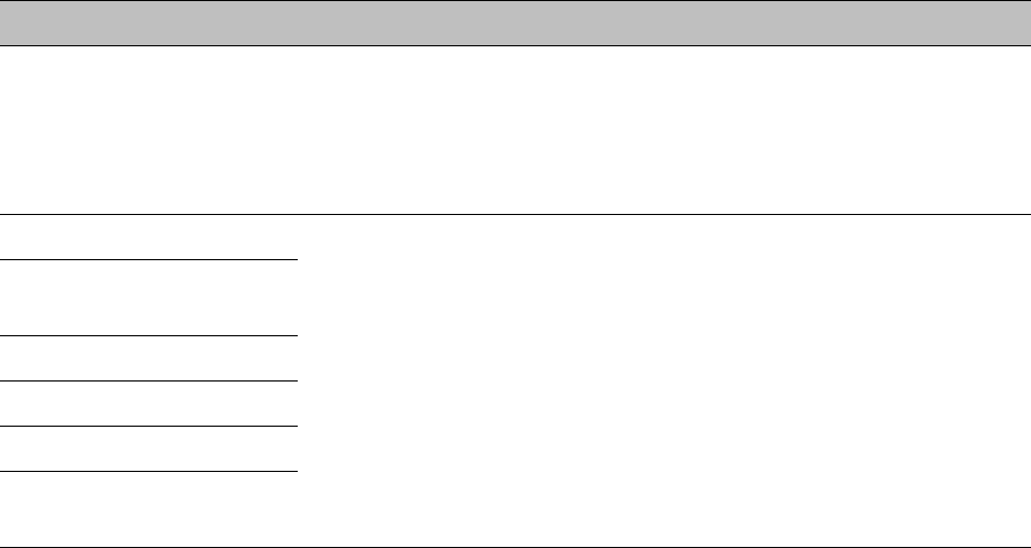
Chapter 7: Configuration
Configuring radio parameters
Page 7-218
Attribute
Meaning
Radio Configuration,
Frame Configuration,
Power Control,
Multicast Data Control
and Advance tab
See Table 122 PMP 450i AP Radio attributes - 5 GHz on page 7-199.
PMP 430 SM Registration
See Table 122 PMP 450i AP Radio attributes - 5 GHz on page 7-199.
PMP 450/430 Legacy
Mode
Control Messages
PMP 430 Interop Mode
Receive Quality Debug
Frame Alignment Legacy
Mode
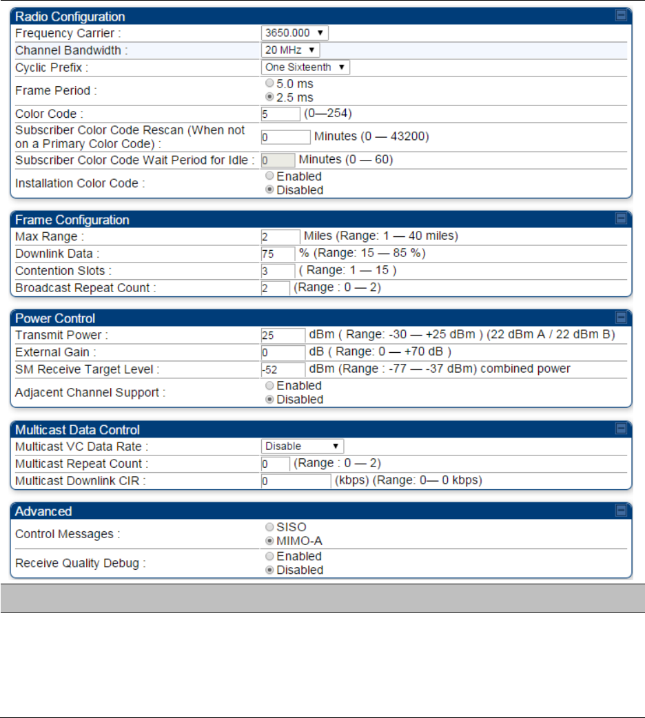
Chapter 7: Configuration
Configuring radio parameters
Page 7-219
Radio page - PMP 450 AP 3.65 GHz
Table 128 PMP 450 AP Radio attributes - 3.65 GHz
Attribute
Meaning
Radio Configuration,
Frame Configuration,
Power Control,
Multicast Data Control
and Advance tab
See Table 122 PMP 450i AP Radio attributes - 5 GHz on page 7-199.
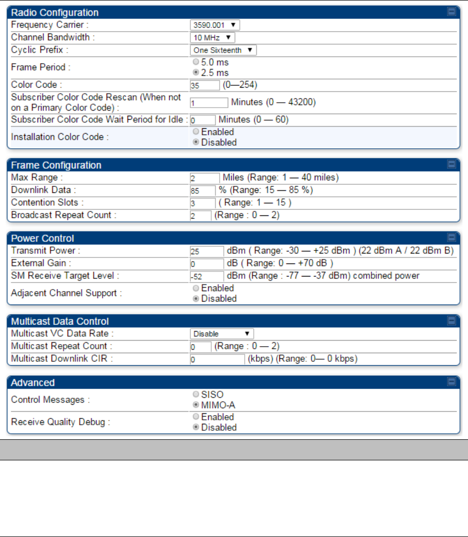
Chapter 7: Configuration
Configuring radio parameters
Page 7-220
Radio page - PMP 450 AP 3.5 GHz
Table 129 PMP 450 AP Radio attributes - 3.5 GHz
Attribute
Meaning
Radio Configuration,
Frame Configuration,
Power Control,
Multicast Data Control
and Advance tab
See Table 122 PMP 450i AP Radio attributes - 5 GHz on page 7-199.
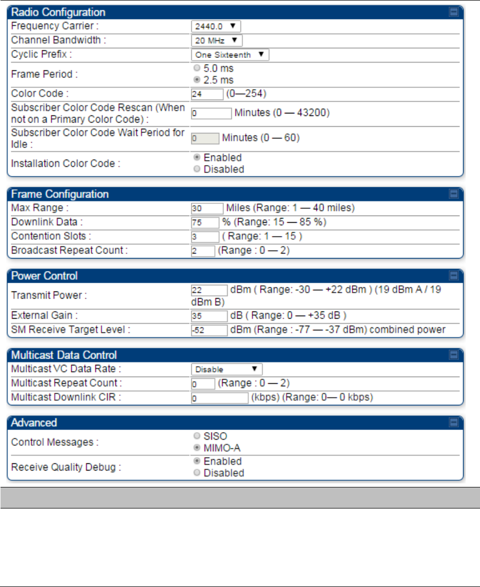
Chapter 7: Configuration
Configuring radio parameters
Page 7-221
Radio page - PMP 450 AP 2.4 GHz
Table 130 PMP 450 AP Radio attributes - 2.4 GHz
Attribute
Meaning
Radio Configuration,
Frame Configuration,
Power Control,
Multicast Data Control
and Advance tab
See Table 122 PMP 450i AP Radio attributes - 5 GHz on page 7-199.
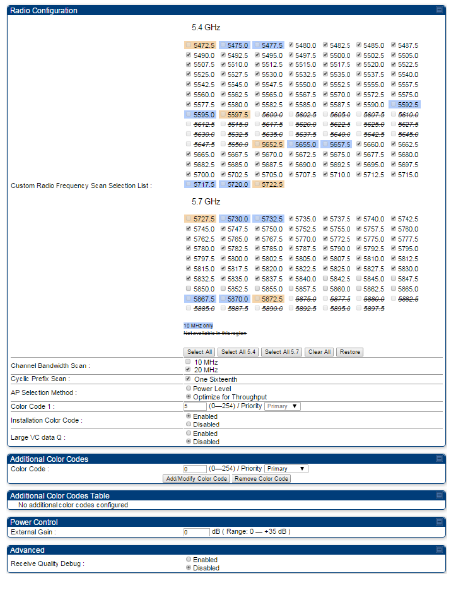
Chapter 7: Configuration
Configuring radio parameters
Page 7-222
Radio page - PMP 450 SM 5 GHz
Table 131 PMP 450 SM Radio attributes – 5 GHz

Chapter 7: Configuration
Configuring radio parameters
Page 7-223
Attribute
Meaning
Custom Radio
Frequency Scan
Selection List
Check the frequencies that SM has to scan for AP transmissions. See
Radio Frequency Scan Selection List on page 7-231.
See Table 122 PMP 450i AP Radio attributes - 5 GHz on page 7-199.
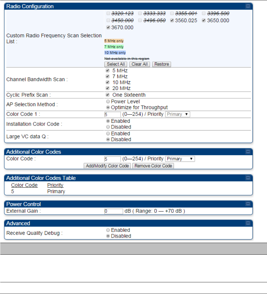
Chapter 7: Configuration
Configuring radio parameters
Page 7-224
Radio page - PMP 450 SM 3.65 GHz
Table 132 PMP 450 SM Radio attributes – 3.65 GHz
Attribute
Meaning
Custom Radio
Frequency Scan
Selection List
Check the frequencies that SM has to scan for AP transmissions. See
Radio Frequency Scan Selection List on page 7-231.
See Table 122 PMP 450i AP Radio attributes - 5 GHz on page 7-199.
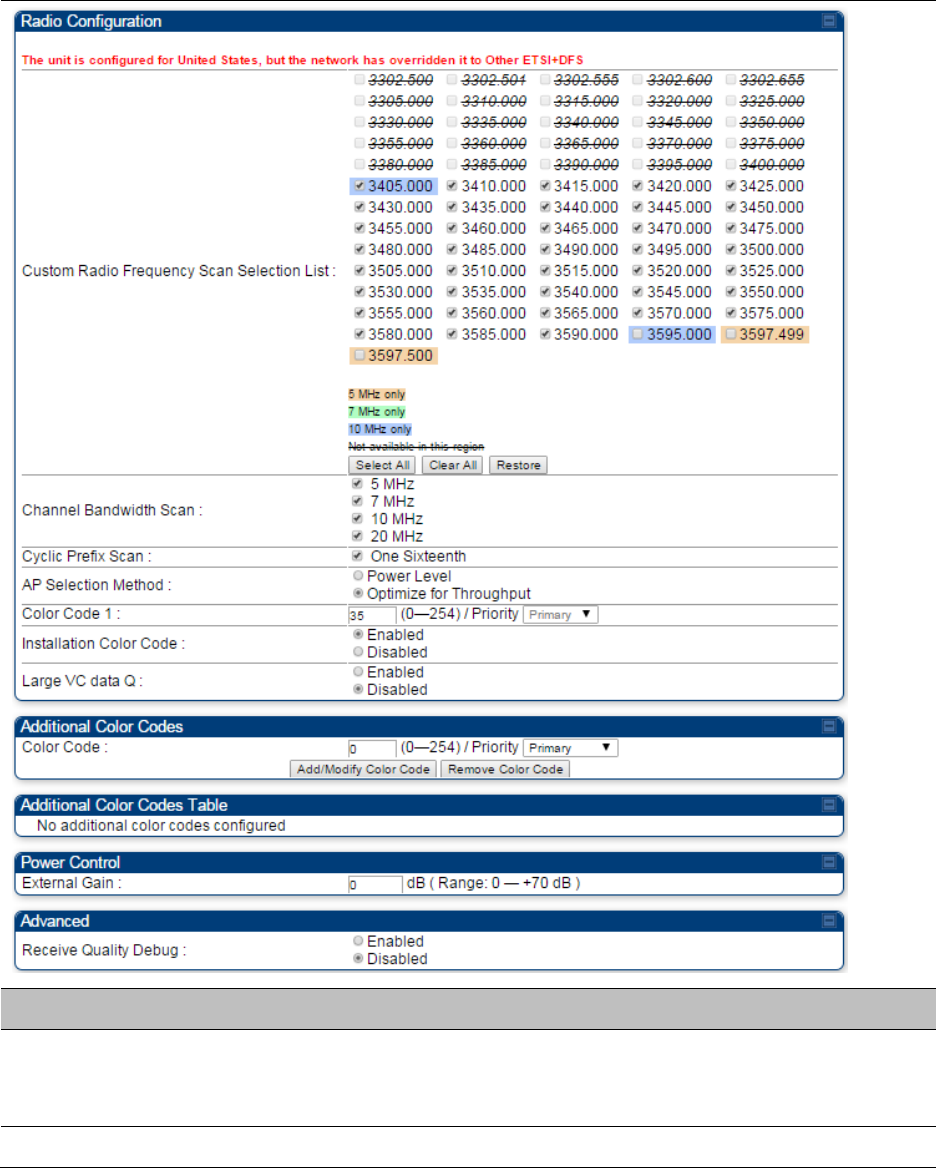
Chapter 7: Configuration
Configuring radio parameters
Page 7-225
Radio page - PMP 450 SM 3.5 GHz
Table 133 PMP 450 SM Radio attributes – 3.5 GHz
Attribute
Meaning
Custom Radio
Frequency Scan
Selection List
Check the frequencies that SM has to scan for AP transmissions. See
Radio Frequency Scan Selection List on page 7-231.
See Table 122 PMP 450i AP Radio attributes - 5 GHz on page 7-199.
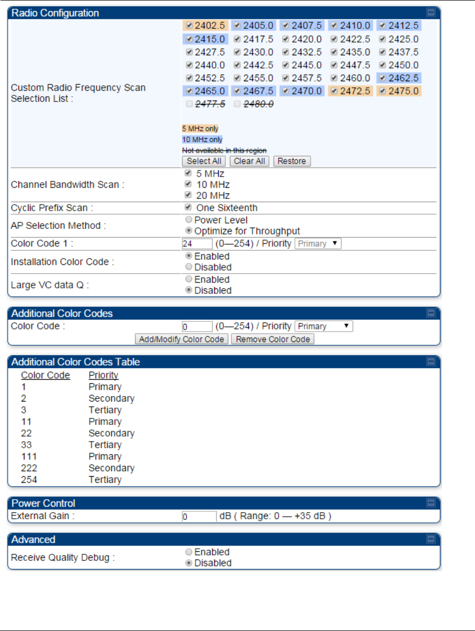
Chapter 7: Configuration
Configuring radio parameters
Page 7-226
Radio page - PMP 450 SM 2.4 GHz
Table 134 PMP 450 SM Radio attributes – 2.4 GHz
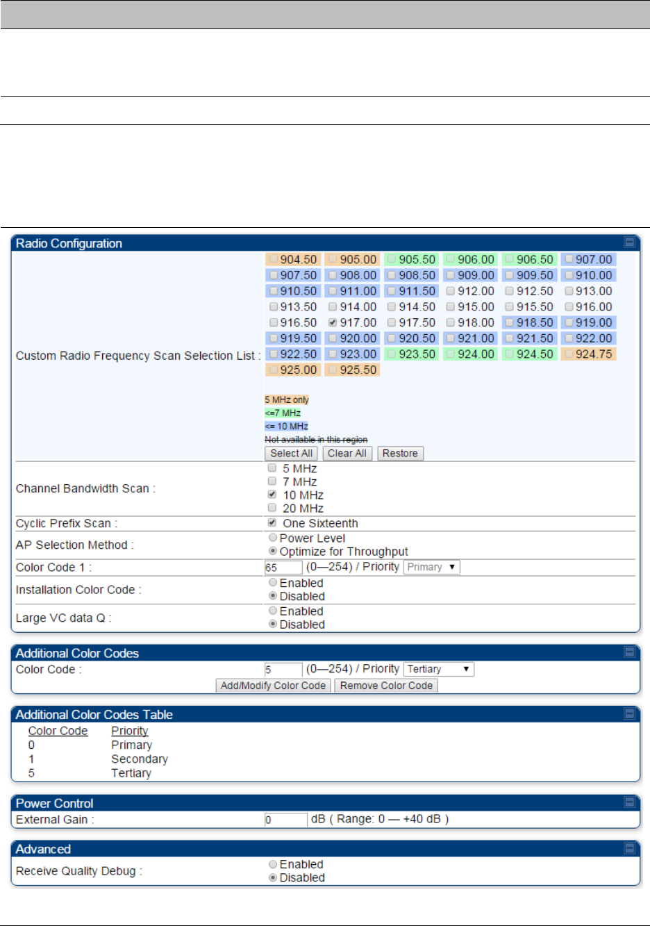
Chapter 7: Configuration
Configuring radio parameters
Page 7-227
Attribute
Meaning
Custom Radio
Frequency Scan
Selection List
Check the frequencies that SM has to scan for AP transmissions. See
Radio Frequency Scan Selection List on page 7-231.
See Table 122 PMP 450i AP Radio attributes - 5 GHz on page 7-199.
Radio page - PMP 450 SM 900 MHz
Table 135 PMP 450 SM Radio attributes –900 MHz
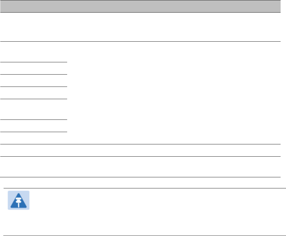
Chapter 7: Configuration
Configuring radio parameters
Page 7-228
Attribute
Meaning
Custom Radio
Frequency Scan
Selection List
See Table 122 PMP 450i AP Radio attributes - 5 GHz on page 7-199.
Channel Bandwidth
Scan
See Table 122 PMP 450i AP Radio attributes - 5 GHz on page 7-199.
Cyclic Prefix Scan
AP Selection Method
Color Code 1
Installation Color
Code
Large VC data Queue
Color Code
External Gain
See Table 122 PMP 450i AP Radio attributes - 5 GHz on page 7-199
Receive Quality
Debug
See Table 122 PMP 450i AP Radio attributes - 5 GHz on page 7-199.
Note
The frequencies that a user can select are controlled by the country or a region and the
Channel Bandwidth selected. There can be a case where a user adds a custom
frequency (from the Custom Frequencies page on page 7-234) and cannot see it in the
pull down menu.
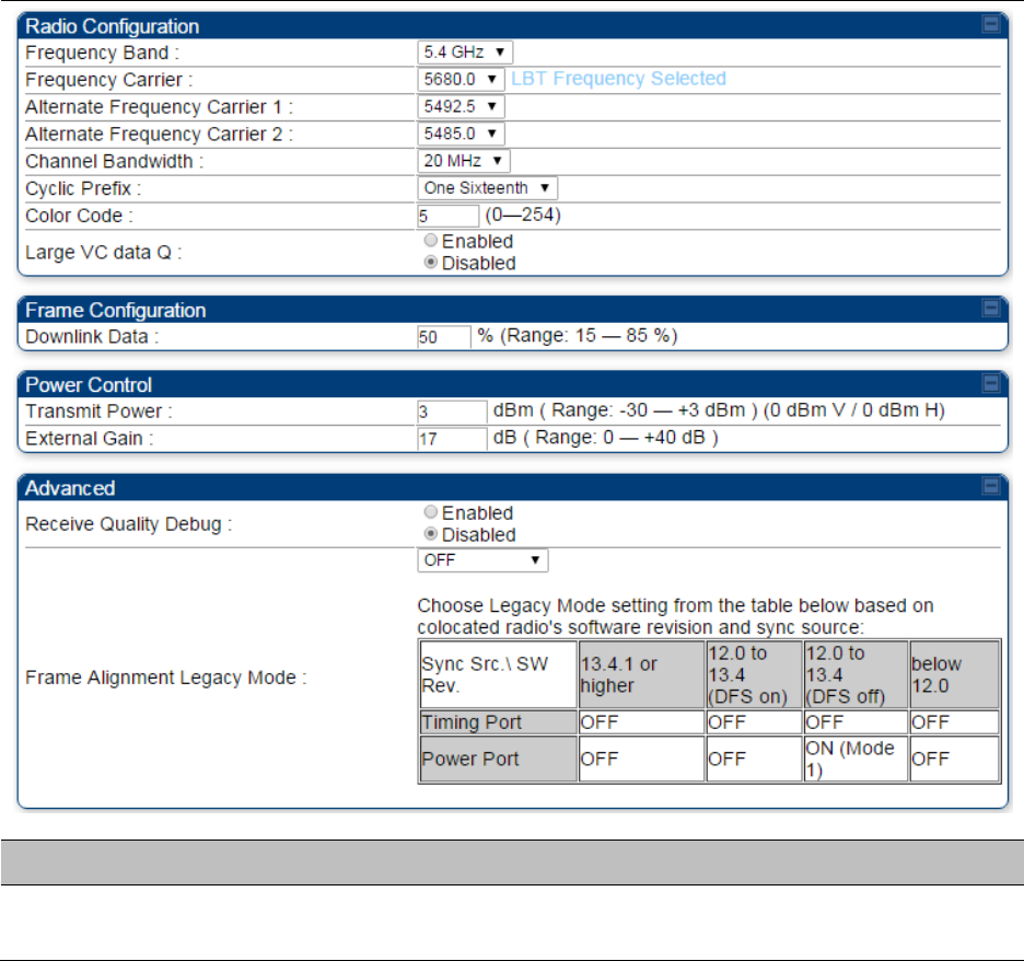
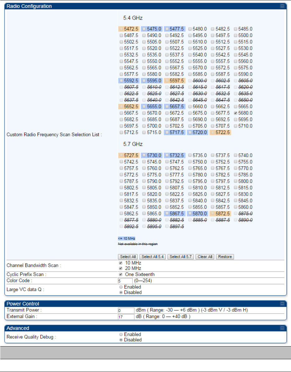
Chapter 7: Configuration
Configuring radio parameters
Page 7-231
Radio Frequency Scan Selection List
The SM or BHS scans complete spectrum as per Full Spectrum Band Scan feature. SMs or BHS
first boot into the smallest selected channel bandwidth (10 MHz, if selected) and scan all selected
frequencies across both the 5.4 GHz and 5.7 GHz frequency bands.
After this scan, if a wider channel bandwidth is selected (20 MHz), the SM/BHS automatically
changes to 20 MHz channel bandwidth and then scans for APs/BHSs. After the SM/BHS finishes
this final scan it will evaluate the best AP/BHM with which to register. If required for registration,
the SM/BHS changes its channel bandwidth back to 10 MHz to match the best AP/BHM.
The SM/BHS will attempt to connect to an AP/BHM based on power level (which affects the
modulation state), channel bandwidth (which affects throughput) and number of SM/BHS
registrations to the AP/BHM (which affects system contention performance).
If it is desired to prioritize a certain AP/BHM over other available APs/BHMs, operators may use the
Color Code Priority feature on the SM/BHS. Utilization of the Color Code feature on the AP/BHM is
recommended to further constrain the AP selection.
If the SM does not find any suitable APs/BHMs for registration after scanning all channel
bandwidths, the SM restarts the scanning process beginning with the smallest configured channel
bandwidth.
Selecting multiple frequencies and multiple channel bandwidths impacts the SM/BHS scanning
time. The biggest consumption of time is in the changing of the SM/BHS channel bandwidth
setting.
The worst case scanning time is approximately two minutes after boot up (SM/BHS with all
frequencies and channel bandwidths selected and registering to an AP/BHM at 10 MHz). If only one
channel bandwidth is selected the time to scan all the available frequencies and register to an
AP/BHM is approximately one minute after boot up.
Other scanning features such as Color Code, Installation Color Code, and RADIUS authentication
are unaffected by the Full Band Scan feature.
Dedicated Multicast Virtual Circuit (VC)
A Multicast VC allows to configure multicast packets to be transmitted over a dedicated channel at
a configurable rate of 1X, 2X, 4X or 8X. This feature is available only for the PMP 450 and PMP 450i
and is not backward compatible with PMP 430 series of radios.
To configure Multicast VC, the AP must have this enabled. This can be enabled in the “Multicast
Data Control” section (under Configuration > Radio page). The default value is “Disable”. If set to
the default value, all multicast packets are transmitted over the Broadcast VC data path. To enable,
select the data rate that is desired for the Multicast VC Data Rate parameter and click Save
Changes button. The radio requires no reboot after any changes to this parameter.
The multicast VC allows three different parameters to be configured on the AP. These can be
changed on the fly and are saved on the flash memory.
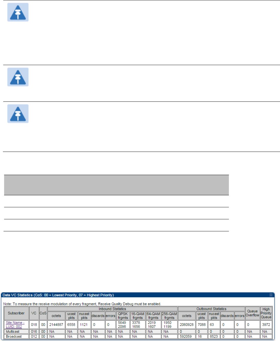
Chapter 7: Configuration
Configuring radio parameters
Page 7-232
Note
If the Multicast VC Data Rate is set to a modulation that the radio is not currently
capable of or operates in non-permitted channel conditions, multicast data is sent but
not received.
Ex: If Multicast VC Data Rate is set to 6x and the channel conditions only permit 4x
mode of operation, then multicast data is sent at 6x modulation but the SM will not
receive the data.
Note
The PMP 450 AP supports up to 119 VCs (instead of 238 VCs) when configured for 30
MHz channel bandwidth or 5 ms Frame Period. This limitation is not applicable for
PMP 450i platform.
Note
Actual Multicast CIR honored by the AP = Configured Multicast CINR/ (Multicast
Repeat Count + 1).
Increasing the Multicast data rate has no impact on the Unicast data rate.
For multicast and unicast traffic mix scenario examples, see Table 138.
Table 138 Example for mix of multicast and unicast traffic scenarios
Repeat
Count
Multicast Data
Rate (Mbps)
Unicast Data
Rate (Mbps)
Aggregate DL Data
Rate (Mbps)
0
10
40
50
1
5
40
45
2
3.33
40
43.33
The statistics have been added to the Data VC page (under Statistics > Data VC). The table displays
the multicast row on the PMP 450 platform AP. The SM displays the multicast row if it is a PMP 450
platform.
Figure 122 Multicast VC statistics
The AP and SM display Transmit and Receive Multicast Data Count (under the Statistics >
Scheduler page), as shown in Figure 123.
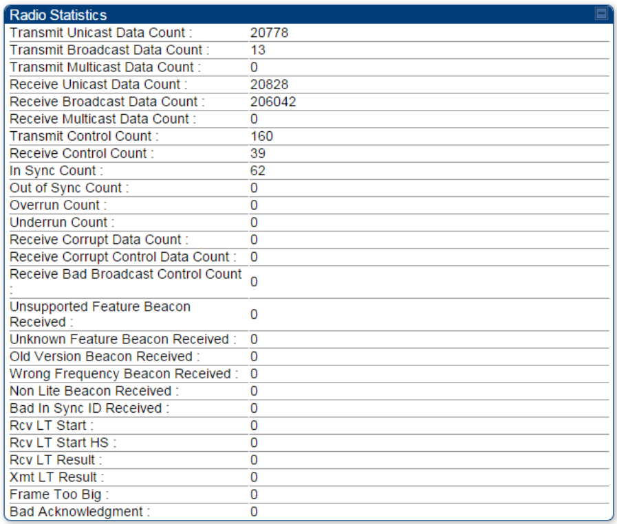
Chapter 7: Configuration
Configuring radio parameters
Page 7-233
Figure 123 Multicast scheduler statistics
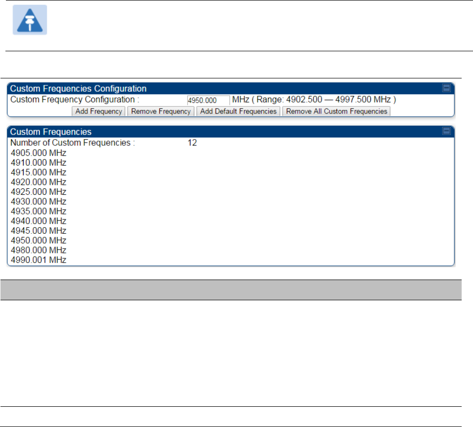
Chapter 7: Configuration
Configuring radio parameters
Page 7-234
Custom Frequencies page
In addition to the Radio tab, AP/SM/BH has another tab called Custom Frequencies as shown in
Table 139.
The custom frequency tab allows to configure custom frequency at 1 KHz raster. It means that the
custom frequencies can be at granularity of 1 KHz e.g. 4910.123 MHz, 4922.333 MHz, 4933.421 MHz
etc.
Note
Ensure that a customer frequency exists before using SNMP to set the radio to a
Custom Frequency.
Table 139 PMP/PTP 450 platform AP/SM/BH Custom Frequencies page – 5 GHz
Attribute
Meaning
Custom Frequency
Configuration
Custom frequencies with a channel raster of 1 KHz can be added from
the available range by keying in the frequency and then clicking the Add
Frequency button. Click Remove Frequency button to delete a specific
frequency keyed in the text box.
Click Default Frequencies button to add a pre-defined list of frequencies
that can be used in this band. This list can be reduced or increased by
manually removing or adding other custom frequencies.
Custom Frequencies
Displays the complete list of user configured custom frequencies.
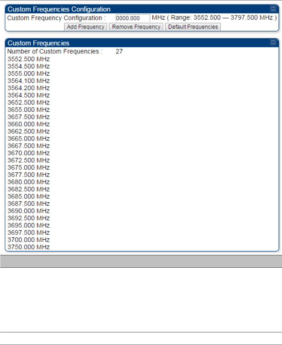
Chapter 7: Configuration
Configuring radio parameters
Page 7-235
Table 140 PMP/PTP 450 SM/BH Custom Frequencies page – 3.65 GHz
Attribute
Meaning
Custom Frequency
Configuration
Custom frequencies with a channel raster of 1 KHz can be added from
the available range by keying in the frequency and then clicking the Add
Frequency button. Click Remove Frequency button to delete a specific
frequency keyed in the text box.
Click Default Frequencies button to add a pre-defined list of frequencies
that can be used in this band. This list can be reduced or increased by
manually removing or adding other custom frequencies.
Custom Frequencies
Displays the complete list of user configured custom frequencies.
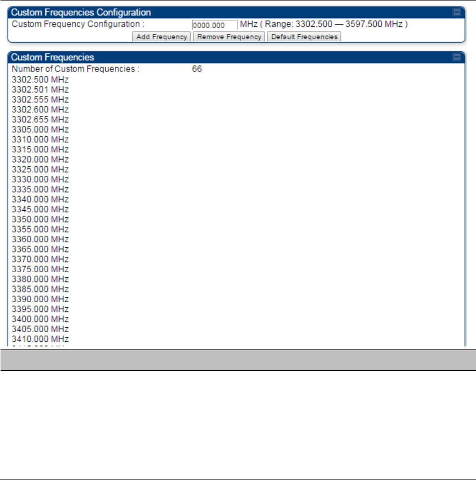
Chapter 7: Configuration
Configuring radio parameters
Page 7-236
Table 141 PMP/PTP 450 SM/BH Custom Frequencies page – 3.5 GHz
Attribute
Meaning
Custom Frequency
Configuration
Custom frequencies with a channel raster of 1 KHz can be added from
the available range by keying in the frequency and then clicking the Add
Frequency button. Click Remove Frequency button to delete a specific
frequency keyed in the text box.
Click Default Frequencies button to add a pre-defined list of frequencies
that can be used in this band. This list can be reduced or increased by
manually removing or adding other custom frequencies.
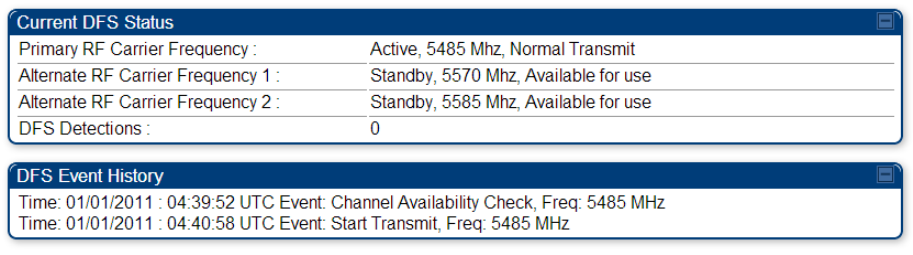
Chapter 7: Configuration
Configuring radio parameters
Page 7-237
DFS for 5 GHz Radios
Dynamic Frequency Selection (DFS) is a requirement in several countries and regions for 5 GHz
unlicensed systems to detect radar systems and avoid co-channel operation. DFS and other
regulatory requirements drive the settings for the following parameters, as discussed in this
section:
Country Code
Primary Frequency
Alternate 1 and Alternate 2 Frequencies
External Antenna Gain
On the AP, the Home > DFS Status page shows current DFS status of all three frequencies and a
DFS log of past DFS events.
Figure 124 AP DFS Status
DFS operation
The ODUs use region-specific DFS based on the Country Code selected on the module’s
Configuration, General page. By directing installers and technicians to set the Country Code
correctly, the operator gains confidence the module is operating according to national or regional
regulations without having to deal with the details for each region.
The details of DFS operation for each Country Code, including whether DFS is active on the AP,
SM, and which DFS regulations apply is shown in Table 229 on page 10-36.

Chapter 7: Configuration
Configuring radio parameters
Page 7-238
Contention slots
The SM uses reserved Contention slots and unused data slots for bandwidth requests.
Uplink Data Slots are used first for data. If they are not needed for data in a given frame, the
remaining data slots can be used by the SMs for bandwidth requests. This allows SMs in sectors
with a small number of Contention slots configured to still successfully transmit bandwidth
requests using unused data slots.
A higher number of Contention slots give higher probability that a SM’s bandwidth request is
correctly received when the system is heavily loaded, but with the tradeoff that sector capacity is
reduced, so there is less capacity to handle the request. The sector capacity reduction is about 200
kbps for each Contention slot configured in a 20 MHz channel at QPSK MIMO-A modulation. The
reduction in sector capacity is proportionally higher at MIMO-B modulations (2 times at QPSK
MIMO-B, 4 times at 16 QAM MIMO-B, 6 times at 64 QAM MIMO-B and 8 times at 256 QAM MIMO-
B). If very few reserved Contention slots are specified, then latency increases in high traffic
periods. If too many are specified, then the maximum capacity is unnecessarily reduced.
The suggested Contention slot settings as a function of the number of active VCs in the sector are
shown in the table below.
Table 142 Contention slots and number of VCs
Number of VCs
Recommended Number of Contention slots
1 to 10
3
11 to 50
4
51 to 150
6
151 and above
8
Note that each SM uses one or two VCs. All SMs have a Low Priority Channel that uses one VC; if
the High Priority Channel is enabled for the SM, then the SM uses a second VC. Therefore the
number of active VCs in a sector is greater than or equal to the number of SMs registered to the
AP in the sector. For example, a network including 20 SMs with High Priority Channel disabled and
20 SMs with High Priority Channel enabled has 60 active VCs and may be configured with 6
Contention slots.
In a typical cluster, each AP must be set to the same number of Contention slots to assure proper
timing in the send and receive cycles. However, where high incidence of small packets exists, as in
a sector that serves several VoIP streams, additional Contention slots may provide better results.
For APs in a cluster of mismatched Contention slots setting, or where PMP 450 is collocated with
radios using different technologies, like PMP 430 or FSK, in the same frequency band, use the
frame calculator. To download the PMP 450 Contention Slots Paper, see
http://www.cambiumnetworks.com/solution-papers/pmp-450-contention-slots.
Chapter 7: Configuration
Configuring radio parameters
Page 7-239
MIMO-A mode of operation
PMP/PTP 450 platform supports MIMO-B mode using the following modulation levels: QPSK, 16-
QAM, 64-QAM and 256-QAM. System Release 13.2 introduces MIMO-A mode of operation using
the same modulation levels as the MIMO-B mode. With MIMO-B, the radio sends different streams
of data over the two antennas whereas with MIMO-A, the radio uses a scheme that tries to
optimize coverage by transmitting the same data over both antennas. This redundancy improves
the signal to noise ratio at the receiver making it more robust, at the cost of throughput.
In addition to introducing MIMO-A modes, improvements have been made to the existing rate
adapt algorithm to switch between MIMO-A and MIMO-B seamlessly without any intervention or
added configuration by the operator. The various modulation levels used by the PMP 450 are
shown in Table 143.
Table 143 PMP/PTP 450 platform Modulation levels
Rate
MIMO-B
MIMO-A
QPSK
2X MIMO-B
1X MIMO-A
16-QAM
4X MIMO-B
2X MIMO-A
64-QAM
6X MIMO-B
3X MIMO-A
265-QAM
8X MIMO-B
4X MIMO-A
System Performance
For System Performance details of all the PMP/PTP 450 platform Series products please refer the
Link Capacity
Planner at:
https://support.cambiumnetworks.com/files/pmp450.

Chapter 7: Configuration
Configuring radio parameters
Page 7-240
Table 144 Co-channel Interference per (CCI) MCS
MCS of Victim
MCS of Interferer
Channel BW (MHz)
CCI
1X (QPSK SISO)
6X (64-QAM MIMO-B)
5, 10, 15, 20 or 30
10 dB
2X (16-QAM SISO)
6X (64-QAM MIMO-B)
5, 10, 15, 20 or 30
17 dB
3X (64-QAM SISO)
6X (64-QAM MIMO-B)
5, 10, 15, 20 or 30
25 dB
1X (QPSK MIMO-A)
6X (64-QAM MIMO-B)
5, 10, 15, 20 or 30
7 dB
2X (16-QAM MIMO-A)
6X (64-QAM MIMO-B)
5, 10, 15, 20 or 30
14 dB
3X (64-QAM MIMO-A)
6X (64-QAM MIMO-B)
5, 10, 15, 20 or 30
22 dB
4X (256-QAM MIMO-A)
6X (64-QAM MIMO-B)
5, 10, 15, 20 or 30
30 dB
2X (QPSK MIMO-B)
6X (64-QAM MIMO-B)
5, 10, 15, 20 or 30
10 dB
4X (16-QAM MIMO-B)
6X (64-QAM MIMO-B)
5, 10, 15, 20 or 30
17 dB
6X (64-QAM MIMO-B)
6X (64-QAM MIMO-B)
5, 10, 15, 20 or 30
25 dB
8X (256-QAM MIMO-B)
6X (64-QAM MIMO-B)
5, 10, 15, 20 or 30
33 dB
Table 145 Adjacent Channel Interference (ACI) per MCS
MCS of Victim
MCS of Interferer
Channel BW (MHz)
ACI
Guard Band
1X (QPSK SISO)
6X (64-QAM MIMO-B)
5, 10, 15, 20 or 30
-16 dB
None
2X (16-QAM SISO)
6X (64-QAM MIMO-B)
5, 10, 15, 20 or 30
-16 dB
None
3X (64-QAM SISO)
6X (64-QAM MIMO-B)
5, 10, 15, 20 or 30
-16 dB
None
1X (QPSK MIMO-A)
6X (64-QAM MIMO-B)
5, 10, 15, 20 or 30
-13 dB
None
2X (16-QAM MIMO-A)
6X (64-QAM MIMO-B)
5, 10, 15, 20 or 30
-13 dB
None
3X (64-QAM MIMO-A)
6X (64-QAM MIMO-B)
5, 10, 15, 20 or 30
-13 dB
None
4X (256-QAM MIMO-A)
6X (64-QAM MIMO-B)
5, 10, 15, 20 or 30
-10 dB
None
2X (QPSK MIMO-B)
6X (64-QAM MIMO-B)
5, 10, 15, 20 or 30
-16 dB
None
4X (16-QAM MIMO-B)
6X (64-QAM MIMO-B)
5, 10, 15, 20 or 30
-16 dB
None
6X (64-QAM MIMO-B)
6X (64-QAM MIMO-B)
5, 10, 15, 20 or 30
-16 dB
None
8X (256-QAM MIMO-B)
6X (64-QAM MIMO-B)
5, 10, 15, 20 or 30
-10 dB
None
Guard Band
No Guard Bands are needed for the 5.4 GHz and 5.8 GHz bands.
Chapter 7: Configuration
Configuring radio parameters
Page 7-241
Improved PPS performance of PMP 450 and 450i SMs
The PMP 450 platforms Series provides improved packets per second (PPS) performance with
regards to the PMP 450. Through hardware and software enhancements, the PPS performance of
the PMP 450i AP has been improved to 40000 packets/second, measured through a standard
RFC2544 test using 64 bytes packets. With this enhancement, operators are able to provide higher
bandwidth including better VoIP and video services to end customers using existing SM
deployments.

Chapter 7: Configuration
Setting up SNMP agent
Page 7-242
Setting up SNMP agent
Operators may use SNMP commands to set configuration parameters and retrieve data from the
AP and SM modules. Also, if enabled, when an event occurs, the SNMP agent on the PMP/PTP 450
platform sends a trap to whatever SNMP trap receivers configured in the management network.
SNMPv2c
SNMPv3
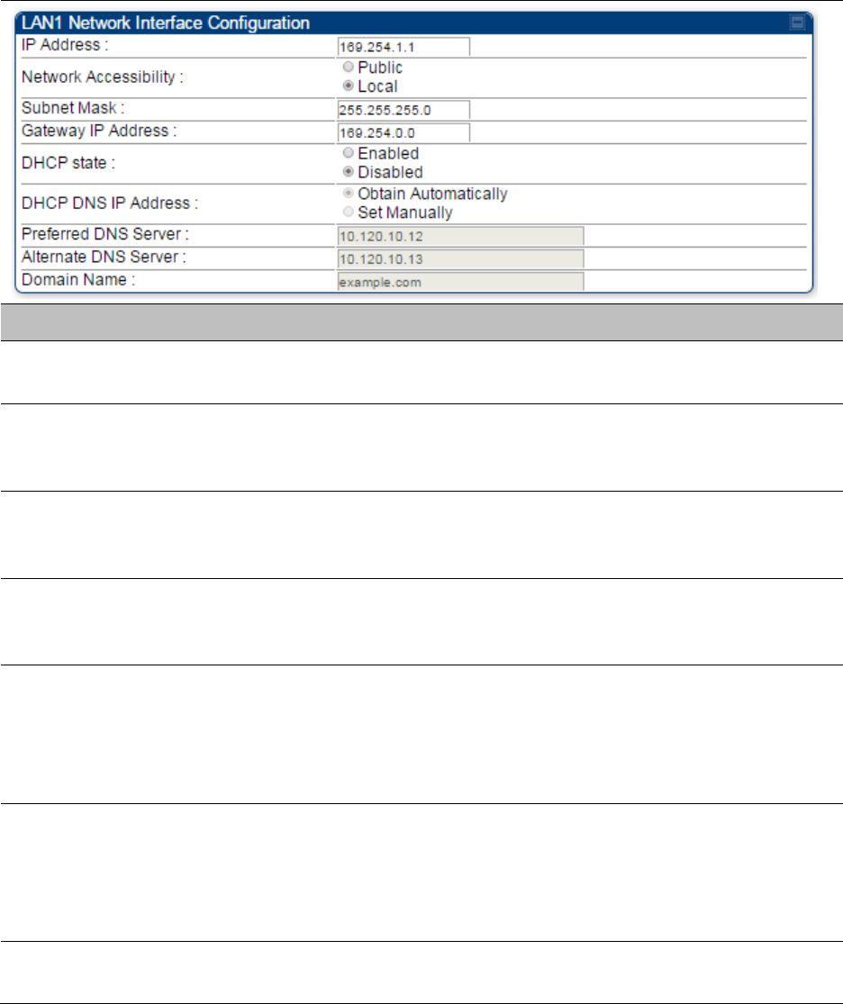
Chapter 7: Configuration
Setting up SNMP agent
Page 7-243
Configuring SM/BHS’s IP over-the-air access
To access the SM/BHS management interface from a device situated above the AP, the SM/BHS’s
Network Accessibility parameter (under the web GUI at Configuration > IP) may be set to Public.
Table 146 LAN1 Network Interface Configuration tab of IP page attributes
Attribute
Meaning
IP Address
Internet Protocol (IP) address. This address is used by family of Internet
protocols to uniquely identify this unit on a network.
Network
Accessibility
Specify whether the IP address of the SM/BHS must be visible to only a
device connected to the SM/BHS by Ethernet (Local) or be visible to the
AP/BHM as well (Public).
Subnet Mask
If Static IP is set as the Connection Type of the WAN interface, then this
parameter configures the subnet mask of the SM/BHS for RF
management traffic.
Gateway IP Address
If Static IP is set as the Connection Type of the WAN interface, then this
parameter configures the gateway IP address for the SM/BHS for RF
management traffic.
DHCP state
If Enabled is selected, the DHCP server automatically assigns the IP
configuration (IP address, subnet mask, and gateway IP address) and the
values of those individual parameters (above) are not used. The setting
of this DHCP state parameter is also viewable (read only), in the Network
Interface tab of the Home page.
DNS IP Address
Canopy devices allow for configuration of a preferred and alternate DNS
server IP address either automatically or manually. Devices must set
DNS server IP address manually when DHCP is disabled for the
management interface of the device. The default DNS IP addresses are
0.0.0.0 when configured manually.
Preferred DNS
Server
The first address used for DNS resolution.

Chapter 7: Configuration
Setting up SNMP agent
Page 7-244
Alternate DNS
Server
If the Preferred DNS server cannot be reached, the Alternate DNS Server
is used.
Domain Name
The operator’s management domain name may be configured for DNS.
The domain name configuration can be used for configuration of the
servers in the operator’s network. The default domain name is
example.com, and is only used if configured as such.
Configuring SNMP
The SNMP page configuration is explained below.
Note
The SNMP page for AP, SM, BHM and BHS has the same parameter attributes.
SNMP page – AP/SM/BHM/BHS
The SNMP page is explained in Table 147.
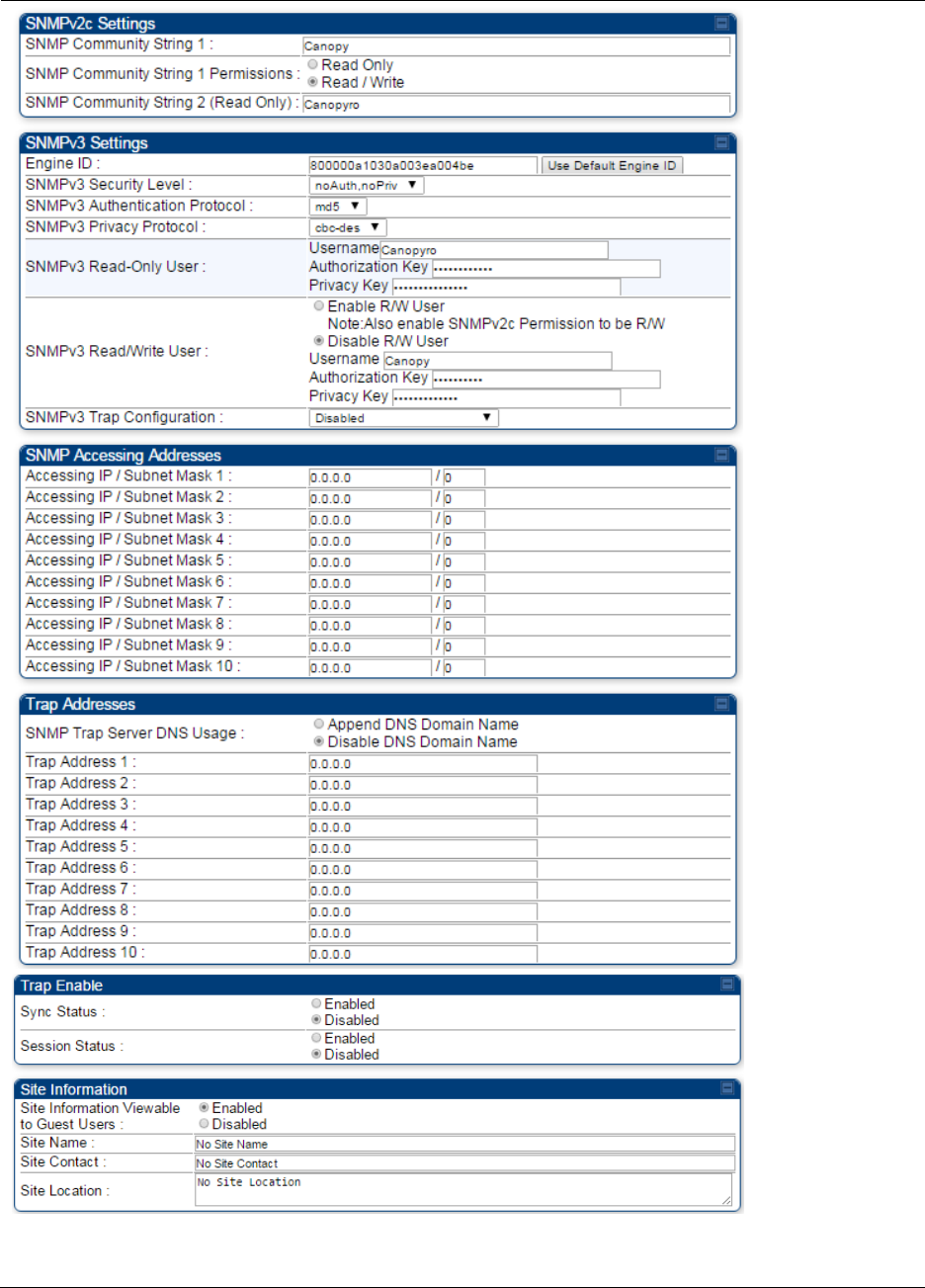
Chapter 7: Configuration
Setting up SNMP agent
Page 7-245
Table 147 SNMP page attributes

Chapter 7: Configuration
Setting up SNMP agent
Page 7-246
Attribute
Meaning
SNMP Community
String 1
Specify a control string that can allow a Network Management Station
(NMS) to access SNMP information. No spaces are allowed in this string.
The default string is Canopy.
SNMP Community
String 1 Permissions
You can designate the SNMP Community String 1 to be the password
for WM, for example, to have Read / Write access to the module via
SNMP or for all SNMP access to the module to be Read Only.
SNMP Community
String 2 (Read Only)
Specify an additional control string that can allow a Network
Management Station (NMS) to read SNMP information. No spaces are
allowed in this string. The default string is Canopyro. This password will
never authenticate a user or an NMS to read/write access.
The Community String value is clear text and is readable by a packet
monitor. Additional security derives from the configuration of the
Accessing Subnet, Trap Address, and Permission parameters.
Engine ID
The Engine ID may be between 5 and 32 hex characters. The hex
character input is driven by RFC 3411 recommendations on the Engine
ID. The default Engine ID is the MAC address of the device
SNMPv3 Security
Level
Specify security model where users are defined and authenticated
before granting access to any SNMP service. Each device can configure
the security level of SNMPv3 to No authentication/No privacy,
Authentication/No privacy, or Authentication/Privacy.
SNMPv3
Authentication
Protocol
Currently, the SNMPv3 authentication protocol MD5 is supported.
SNMPv3 Privacy
Protocol
Currently, the SNMPv3 privacy protocol CBC-DES is supported.
SNMPv3 Read-Only
User
This filed allows for a read-only user per devices. The default values for
the Read-Only users is:
Username = Canopyro
Authentication Password = authCanopyro
Privacy Password = privacyCanopyro
SNMPv3 Read/Write
User
Read-write user by default is disabled. The default values for the
Read/Write users is :
Username = Canopy
Authentication Password = authCanopy
Privacy Password = privacyCanopy
SNMPv3 Trap
Configuration
When enabling transmission of SNMPv3 traps the read-only or read-
write user credentials must be used and selected properly in order for
the SNMP manager to correctly interpret the traps. By default
transmission of SNMPv3 traps is disabled and all traps sent from the
radios are in SNMPv2c format.

Chapter 7: Configuration
Setting up SNMP agent
Page 7-247
Accessing IP /
Subnet Mask 1 to 10
Specify the addresses that are allowed to send SNMP requests to this
AP. The NMS has an address that is among these addresses (this
subnet). You must enter both
The network IP address in the form xxx.xxx.xxx.xxx
The CIDR (Classless Interdomain Routing) prefix length in the form
/xx
For example:
the /16 in 198.32.0.0/16 specifies a subnet mask of 255.255.0.0 (the
first 16 bits in the address range are identical among all members of
the subnet).
192.168.102.0 specifies that any device whose IP address is in the
range 192.168.102.0 to 192.168.102.254 can send SNMP requests to
the AP, presuming that the device supplies the correct Community
String value.
The default treatment is to allow all networks access. For more
information on CIDR, execute an Internet search on “Classless
Interdomain Routing.” You are allowed to specify as many as 10
different accessing IP address, subnet mask combinations.
RECOMMENDATION:
The subscriber can access the SM/BHS by changing the subscriber
device to the accessing subnet. This hazard exists because the
Community String and Accessing Subnet are both visible parameters.
To avoid this hazard, configure the SM/BHS to filter (block) SNMP
requests.
SNMP Trap Server
DNS Usage
The management DNS domain name may be toggled such that the
name of the trap server only needs to be specified and the DNS domain
name is automatically appended to that name. The default SNMP trap
server addresses for all 10 available servers is 0.0.0.0 with the appending
of the DNS domain name disabled.
Trap Address 1 to 10
Specify ten or fewer IP addresses (xxx.xxx.xxx.xxx) or DNS names to
which SNMP traps must be sent. Traps inform Wireless Manager or an
NMS that something has occurred. For example, trap information is sent
after a reboot of the module.
when an NMS attempts to access agent information but either
supplied an inappropriate community string or SNMP version
number.
is associated with a subnet to which access is disallowed.
Trap Enable, Sync
Status
If the sync status traps (sync lost and sync regained) have to be sent to
Wireless Manager or an NMS, select Enabled. If these traps have to be
suppressed, select Disabled.
Trap Enable, Session
Status
If you want session status traps sent to Wireless Manager or an NMS,
select Enabled.

Chapter 7: Configuration
Setting up SNMP agent
Page 7-248
Site Information
Viewable to Guest
Users
Operators can enable or disable site information from appearing when a
user is in GUEST account mode.
Site Name
Specify a string to associate with the physical module. This parameter is
written into the sysName SNMP MIB-II object and can be polled by
Wireless Manager or an NMS. The buffer size for this field is 128
characters.
Site Contact
Enter contact information for the module administrator. This parameter
is written into the sysContact SNMP MIB-II object and can be polled by
Wireless Manager or an NMS. The buffer size for this field is 128
characters.
Site Location
Enter information about the physical location of the module. This
parameter is written into the sysLocation SNMP MIB-II object and can be
polled by Wireless Manager or an NMS. The buffer size for this field is
128 characters.

Chapter 7: Configuration
Configuring syslog
Page 7-250
Syslog event logging
Following events are logged in syslog as explained in Table 148.
Table 148 Syslog parameters
Attribute
Meaning
Timestamp
All syslog messages captured from the radio have a timestamp.
Configuration
Changes
This includes any device setting that has changed and includes the old
or new parameter value, including the device reboots.
User Login and
Logout
Syslog records each user login and logout, with username.
Add or Delete of user
accounts through
GUI and SNMP
Syslog captures any user accounts that are added or deleted.
Spectrum Analysis
Syslog records a message every time Spectrum Analysis runs.
Note
Since the AP/BHM must be set to a SM/BHS for Spectrum
Analysis, syslog messages are not reported from the radio
until the scan is done and the radio mode is switched back
to AP/BHM.
Link Test
Syslog records a message every time a Link Test is run.
Clear Statistics
Syslog sends a message when Statistics are cleared. This is done
individually for each statistics page that is cleared.
SM Register or De-
register
Syslog records a message when a SM registers or deregisters.
BHS Connect or
Disconnect
Syslog records a message when a BHS connects or disconnects.
Configuring system logging
To configure system logging, select the menu option Configuration > Syslog.
Syslog page of AP/BHM
The Syslog Configuration page for AP/BHM is shown in Table 149.
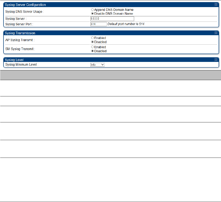
Chapter 7: Configuration
Configuring syslog
Page 7-251
Table 149 Syslog Configuration attributes - AP
Attribute
Meaning
Syslog DNS Server Usage
To configure the AP/BHM to append or not append the DNS server
name to the syslog server name.
Syslog Server
The dotted decimal or DNS name of the syslog server address.
Syslog Server Port
The syslog server port (default 514) to which syslog messaging is
sent.
AP Syslog Transmit
Or BHM Syslog Transmit
When enabled, syslog messages are sent from the AP/BHM.
SM Syslog Transmit
Or BHS Syslog Transmit
When enabled, syslog messages are sent from all the registered
SMs/BHS, unless they are individually set to override this.
Syslog Minimum Level
This provides a selection for the minimum syslog message severity
that is sent to the syslog server. Values range from fatal (highest
severity and least verbose) to info (lowest severity, maximum
verbosity).
For example: If the Syslog Minimum Level is set to notice, then only
messages with severity notice and above are sent.
Syslog page of SM
To configure system logging, select the menu option Configuration > Syslog. The Syslog
Configuration page is shown in Table 150.
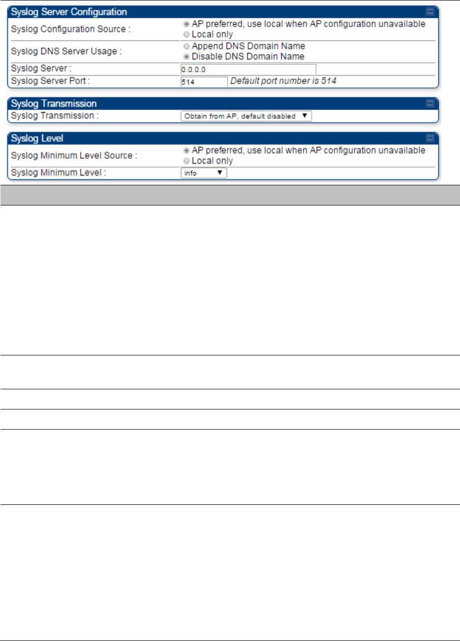
Chapter 7: Configuration
Configuring syslog
Page 7-252
Table 150 Syslog Configuration attributes - SM
Attribute
Meaning
Syslog Configuration
Source
This control determines whether the SM will attempt to use the syslog
server definition from the AP, or whether it will use a local server
definition.
When set to AP preferred, use local when AP configuration unavailable,
and if the SM can register with an AP, then it uses the syslog server
defined on that AP. If the SM cannot register then it will syslog to its
locally defined syslog server through its wired connection, if any.
When set to Local only the SM ignores the AP’s definition of the syslog
server and allows the syslog server to be configured individually for
each SM.
Syslog DNS Server
Usage
To configure the SM to append or not the DNS server name to the
syslog server name.
Syslog Server
The dotted decimal or DNS name of the syslog server address.
Syslog Server Port
The syslog server port (default 514) to which syslog messaging is sent.
Syslog Transmission
Controls the SMs ability to transmit syslog messages. When set to
“Learn from AP” the AP will control whether this SM transmits syslog
messages. When set to “enable” or “disable” the SM will control
whether it sends syslog messages. This allows an operator to override
the AP settings for individual SMs in a sector.
Syslog Minimum
Level Source
This control determines whether the SM attempts to use the minimum
syslog level defined by the AP, or whether it uses a local defined value
using the “Syslog Minimum Level” parameter.
When set to “AP preferred, use local when AP configuration
unavailable”, and if the SM can register with an AP, then it uses the
Syslog Minimum Level defined on that AP. If the SM cannot register
then it uses its own Syslog Minimum Level setting.
When set to “Local only” the SM will always use its own Syslog
Minimum Level setting and ignores the AP’s setting.
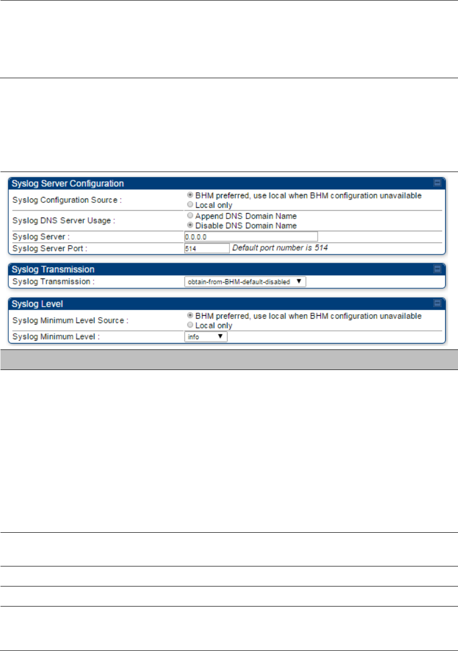
Chapter 7: Configuration
Configuring syslog
Page 7-253
Syslog Minimum
Level
This provides a selection for the minimum syslog message severity that
is sent to the syslog server. Values range from fatal (highest severity and
least verbose) to info (lowest severity, maximum verbosity).
For example: If the Syslog Minimum Level is set to notice, then only
messages with severity notice and above are sent.
Syslog page of BHS
The Syslog Configuration page is shown in Table 151.
Table 151 Syslog Configuration attributes - BHS
Attribute
Meaning
Syslog Configuration
Source
This control determines whether the BHS will attempt to use the syslog
server definition from the BHM, or whether it will use a local server
definition.
When set to BHM preferred, use local when BHM configuration
unavailable, and if the BHS can register with a BHM, then it uses the
syslog server defined on that BHM. If the BHS cannot register then it
will syslog to its locally defined syslog server through its wired
connection, if any.
When set to Local only the BHS ignores the BHM’s definition of the
syslog server and allows the syslog server to be configured
individually for each BHS.
Syslog DNS Server
Usage
To configure the BHS to append or not to append the DNS server name
to the syslog server name.
Syslog Server
The dotted decimal or DNS name of the syslog server address.
Syslog Server Port
The syslog server port (default 514) to which syslog messaging is sent.
Syslog Transmission
Controls the BHSs ability to transmit syslog messages. When set to
Learn from BHM the BHM will control whether this BHS transmits
syslog messages. When set to enable or disable the BHS will control

Chapter 7: Configuration
Configuring syslog
Page 7-254
whether it sends syslog messages. This allows an operator to override
the BHM settings for individual BHSs in a sector.
Syslog Minimum
Level Source
This control determines whether the BHS attempts to use the minimum
syslog level defined by the BHM, or whether it uses a local defined value
using the Syslog Minimum Level parameter.
When set to BHM preferred, use local when BHM configuration
unavailable, and if the BHS can register with a BHM, then it uses the
Syslog Minimum Level defined on that BHM. If the BHS cannot
register then it uses its own Syslog Minimum Level setting.
When set to Local only the BHS will always use its own Syslog
Minimum Level setting and ignores the BHM’s setting.
Syslog Minimum
Level
This provides a selection for the minimum syslog message severity that
is sent to the syslog server. Values range from fatal (highest severity and
least verbose) to info (lowest severity, maximum verbosity).
For example: If the Syslog Minimum Level is set to notice, then only
messages with severity notice and above are sent.
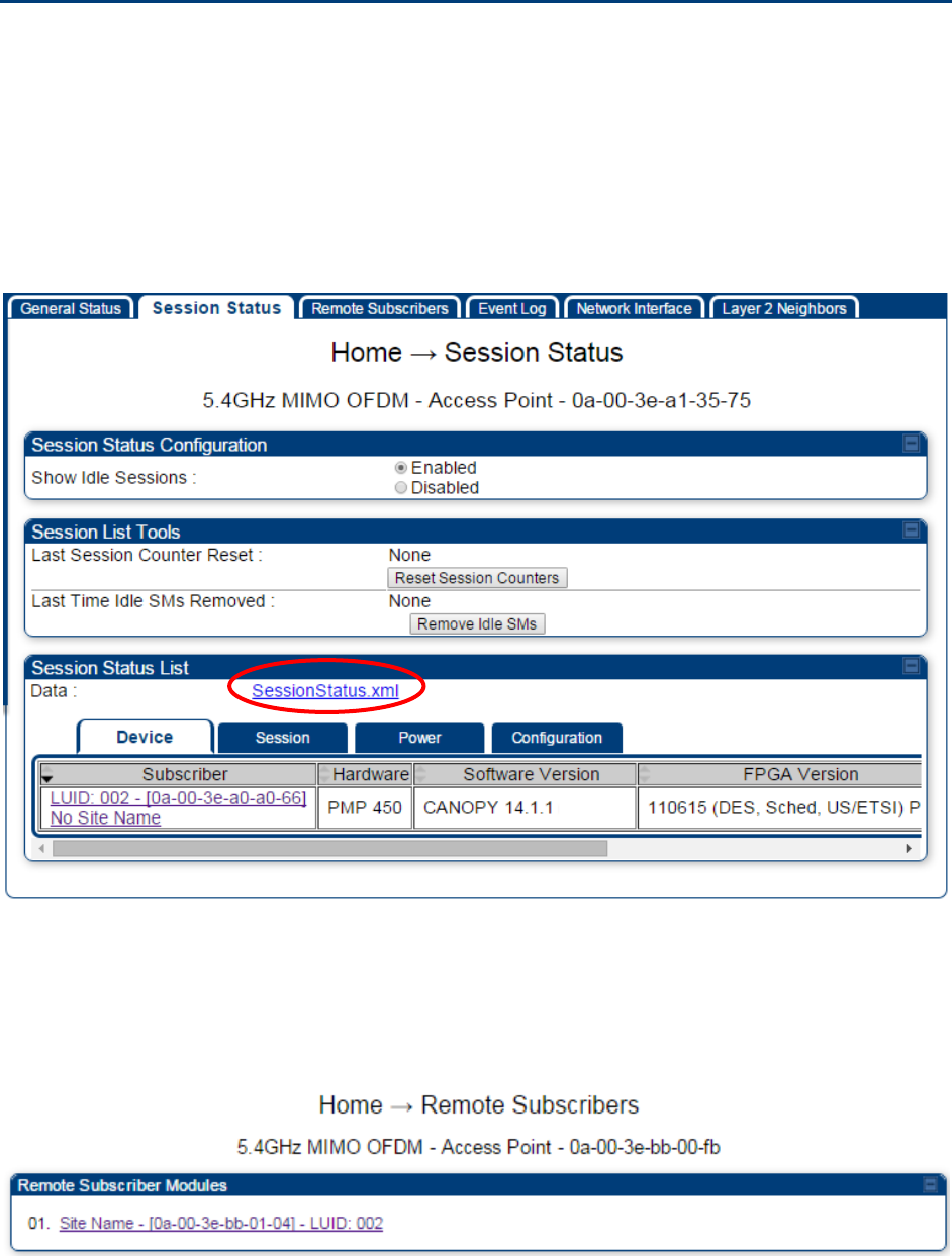
Chapter 7: Configuration
Configuring remote access
Page 7-255
Configuring remote access
Accessing SM/BHS over-the-air by Web Proxy
The SM/BHS may be accessed via the AP/BHM management GUI by navigating to Home > Session
Status (or Home > Remote Subscribers for AP only) and clicking on the SM’s hyperlink.
For example, to access one of the SMs, click LUID: 002 – [0a-00-3e-37-b9-fd], as shown in Figure
125.
Figure 125 AP Session Status page
The SessionStatus.xml hyper link allows user to export all displayed SM data in Session Status
table into an xml file.
To access any one of the SMs, click PMP450 platform SM hyperlink, as shown in Figure 126.
Figure 126 AP Remote Subscribers page
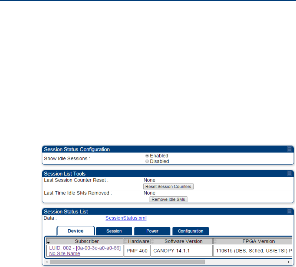
Chapter 7: Configuration
Monitoring the Link
Page 7-256
Monitoring the Link
Link monitoring procedure
After configuring the link, either an operator in the network office or the SM/BHS INSTALLER user
in the field (if read access to the AP/BHM is available to the INSTALLER) must perform the
following procedure. Who is authorized and able to do this depends on local operator password
policy, management VLAN setup and operational practices.
To monitor the link for performance, follow these instructions:
Procedure 22 Monitoring the AP-SM link
1
Access the web interface of the AP/BHM
2
In the left-side menu of the AP/BHM interface, select Home.
3
Click the Session Status tab.
Figure 127 Session Status page
4
The Device tab of Session Status List display all displayed SMs – MAC address,
PMP/PTP Hardware, Software Version, FPGA Version and State
Chapter 7: Configuration
Monitoring the Link
Page 7-257
5
Click Session Count tab of Session Status List to display values for Session Count, Reg
Count, and Re-Reg Count.
Session Count: This field displays how many sessions the SM/BHS has had with
the AP/BHM. Typically, this is the sum of Reg Count and Re-Reg Count. However,
the result of internal calculation may display here as a value that slightly differs
from the sum.
Reg Count: When a SM/BHS makes a Registration Request, the AP/BHM checks its
local session database to see whether it was registered earlier. If the AP/BHM
concludes that the SM/BHS is not currently in session database and it is valid
Registration Request, then the request increments the value of this field.
Re-Reg Count: When a SM/BHS makes a Registration Request, the AP/BHM checks
its local session database to see whether it was registered earlier. If the AP/BHM
concludes that the SM/BHS is currently in session database, then the request
increments the value of this field.
Typically, a Re-Reg is the case where both
o SM/BHS attempts to reregister for having lost communication with the
AP/BHM.
o AP/BHM has not yet observed the link to the SM/BHS as being down.
See Session tab on page 9-17
6
Click Power tab of Session Status list to display Downlink Rate, AP Rx Power (dBm),
Signal Strength Radio (dB) for Uplink and Signal to Noise Radio (dB) for Uplink.
See Power tab on page 9-19
7
Click Configuration tab of Session Status list to get QoS configuration details:
Sustained Data Rate (kbps)
Burst Allocation (kbit)
Max Burst Rate (kbit)
Low Priority CIR (kbps)
See Configuration tab on page 9-20
8
Briefly monitor these values, occasionally refreshing this page by clicking another tab
and then the Session Status tab again.
9
If these values are low (for example, 1, 1, and 0, respectively, meaning that
the SM/BHS registered and started a stable session once) and are not changing:
Consider the installation successful.
Monitor these values from the network office over the next several hours and days.
If these values are greater than 1, 1, and 0, or they increase while you are monitoring
them, troubleshoot the link. (For example, Use Receive Power Level for aiming and
then use Link Tests to confirm alignment).
Refer Viewing Session Status on page 9-16 for more details.
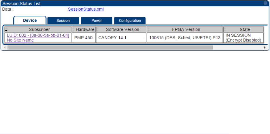
Chapter 7: Configuration
Monitoring the Link
Page 7-258
Exporting Session Status page of AP/BHM
The SessionStatus.xml hyper link allows user to export all displayed SMs or BHS data in Session
Status table into an xml file.
Figure 128 Exporting Session Status page of PMP 450i AP
In case of PMP, if the session status page does not list any SM, the SessionStatus.xml will still be
visible but the file would be empty. The file will contain data from all of the 5 different tables.
Export from command line
The scripts users can also get this file from command line, you have to authenticate successfully in
order to download the file.
Wget
http://169.254.1.1/SessionStatus.xml?CanopyUsername=test&CanopyPassword=test

Chapter 7: Configuration
Configuring quality of service
Page 7-259
Configuring quality of service
Maximum Information Rate (MIR) Parameters
Point-to-multipoint links use the following MIR parameters for bandwidth management:
Sustained Uplink Data Rate (kbps)
Uplink Burst Allocation (kb)
Sustained Downlink Data Rate (kbps)
Downlink Burst Allocation (kb)
Max Burst Downlink Data Rate (kbps)
Max Burst Uplink Data Rate (kbps)
Set each of these parameters per AP or per SM independently.
Token Bucket Algorithm
The software uses a token bucket algorithm that has the following features:
Stores credits (tokens) for the SM to spend on bandwidth for reception or transmission.
Drains tokens during reception or transmission.
Refills with tokens at the sustained rate set by the network operator.
For each token, the SM can send toward the network in the uplink (or the AP can send toward the
SM in the downlink) an equivalent number of kilobits. Two buckets determine the permitted
throughput: one in the SM for uplink and one in the AP for downlink.
The applicable set of Uplink Burst Allocation and Downlink Burst Allocation parameters determine
the number of tokens that can fill each bucket. When the SM transmits (or the AP transmits) a
packet, the equivalent number of tokens is removed from the uplink (or downlink) bucket.
Except when full, the bucket is continuously being refilled with tokens at rates that the applicable
set of Sustained Uplink Data Rate and Sustained Downlink Data Rate parameters specify. The
bucket often drains at a rate that is much faster than the sustained data rate but can refill at only
the sustained data rate. Thus, the effects of the allocation and rate parameters on packet delay are
as follows:
The burst allocation affects how many kilobits are processed before packet delay is imposed.
The sustained data rate affects the packet delay that is imposed.

Chapter 7: Configuration
Configuring quality of service
Page 7-260
MIR Data Entry Checking
Uplink and downlink MIR is enforced as shown in Figure 129.
Note
In these figures, entry refers to the setting in the data rate parameter, not the burst
allocation parameter.
Figure 129 Uplink and downlink rate caps adjusted to apply aggregate cap
For example, in the SM, if you set the Sustained Uplink Data Rate parameter to 2,000 kbps and the
Sustained Downlink Data Rate parameter to 10,000 kbps, then the uplink and downlink MIR that is
enforced for the SM can be calculated as shown in Figure 130.
Figure 130 Uplink and downlink rate cap adjustment example
`
In this example case, the derived 1,167-kbps uplink and 5,833-kbps downlink MIR sum to the fixed
7,000-kbps aggregate cap of the SM.
Committed Information Rate (CIR)
The Committed Information Rate (CIR) capability feature enables the service provider to guarantee
to any subscriber that bandwidth will never decrease to below a specified minimum unless CIR is
oversubscribed or RF conditions are degraded. CIR is oversubscribed when there is not enough
available bandwidth to support CIR configuration for all subscribers. In this condition, SMs which
are configured with a nonzero CIR will all operate at the maximum data rate supported by the link
(subject to Maximum Information Rate and Burst Rate/Allocations). SMs which are configured with
a CIR of 0 kbps will not transmit until CIR-configured SMs have completed transmission. CIR may
be configured independently for high priority traffic and for low priority traffic.
CIR parameters may be configured in the following ways:
Web-based management GUI
SNMP
Authentication Server (RADIUS) - when a SM successfully registers and authenticates, CIR
information is retrieved from the RADIUS server.
uplink cap enforced = uplink entry x aggregate cap for the SM
uplink entry + downlink entry
downlink cap enforced = downlink entry x aggregate cap for the SM
uplink entry + downlink entry
uplink cap enforced = 2,000 kbps x 7,000 kbps
2,000 kbps + 10,000 kbps = 1,167 kbps
downlink cap enforced = 10,000 kbps x 7,000 kbps
2,000 kbps + 10,000 kbps = 5,833 kbps
Chapter 7: Configuration
Configuring quality of service
Page 7-261
Active CIR configuration can be verified via the AP’s Home > Session Status page.
Bandwidth from the SM Perspective
In the SM, normal web browsing, e-mail, small file transfers and short streaming video are rarely
rate limited with practical bandwidth management (QoS) settings. When the SM processes large
downloads such as software upgrades and long streaming video or a series of medium-size
downloads, the bucket rapidly drains, the burst limit is reached, and some packets are delayed.
The subscriber experience is more affected in cases where the traffic is more latency sensitive.
Interaction of Burst Allocation and Sustained Data Rate
Settings
If the Burst Allocation is set to 1200 kb and the Sustained Data Rate is set to 128 kbps, a data burst
of 1000 kb is transmitted at full speed because the Burst Allocation is set high enough. After the
burst, the bucket experiences a significant refill at the Sustained Data Rate. This configuration uses
the advantage of the settable Burst Allocation.
If both the Burst Allocation and the Sustained Data Rate are set to 128 kb, a burst is limited to the
Burst Allocation value. This configuration does not take advantage of the settable Burst Allocation.
If the Burst Allocation is set to 128 kb and the Sustained Data Rate is set to 256 kbps, the actual
rate is the burst allocation (but in kbps). As above, this configuration does not take advantage of
the settable Burst Allocation.
High-priority Bandwidth
To support low-latency traffic such as VoIP (Voice over IP) or video, the system implements a high-
priority channel. This channel does not affect the inherent latencies in the system but allows high-
priority traffic to be immediately served. The high-priority pipe separates low-latency traffic from
traffic that is latency tolerant, such as standard web traffic and file downloads.
The number of channels available on the AP is reduced by the number of SMs configured for the
high-priority channel (each SM operating with high-priority enabled uses two channels (virtual
circuits) instead of one).
A module prioritizes traffic by
reading the Low Latency bit (Bit 3) in the IPv4 Type of Service (ToS) byte in a received packet.
Bit 3 is set by a device outside the system.
reading the 802.1p field of the 802.1Q header in a received packet, where VLAN is enabled on
the module.
comparing the 6-bit Differentiated Services Code Point (DSCP) field in the ToS byte of a
received packet to a corresponding value in the Diffserv tab of the Configuration page of the
module. A packet contains no flag that indicates whether the encoding is for the Low Latency
bit or the DSCP field. For this reason, you must ensure that all elements in your trusted
domain, including routers and endpoints, set and read the ToS byte with the same scheme.
Modules monitor ToS bytes with DSCP fields, but with the following differences:
The 6-bit length of the field allows it to specify one of 64 service differentiations.

Chapter 7: Configuration
Configuring quality of service
Page 7-262
These correlate to 64 individual (CodePoint) parameters in the Diffserv tab of the Configuration
page.
Per RFC 2474, 3 of these 64 are preset and cannot be changed. (See
http://www.faqs.org/rfcs/rfc1902.html.)
For any or all of the remaining 61 CodePoint parameters, you can specify a value of
o 0 through 3 for low-priority handling.
o 4 through 7 for high-priority handling.
Note
Ensure that your Differentiated Services domain boundary nodes mark any entering
packet, as needed, so that it specifies the appropriate Code Point for that traffic and
domain. This prevents theft of service level.
An example of the Diffserv page in the Configuration menu and parameter descriptions are
provided under DiffServ attributes – AP/BHM on page 7-131. This tab and its rules are identical
from module type to module type. However, any of the 61 configurable Code Points can be set to a
different value from module to module, thus defining unique per-hop behavior for some traffic.
This tab in the AP sets the priorities for the various packets in the downstream (sent from the
public network). This tab in the SM sets the priorities for the various packets in the upstream (sent
to the public network).
Typically, some SMs attach to older devices that use the ToS byte as originally formatted, and
others to newer devices that use the DSCP field. The default values in the Diffserv page allow your
modules to prioritize traffic from the older devices roughly the same as they traditionally have.
However, these default values may result in more high-priority traffic as DSCP fields from the
newer devices are read and handled. So, after making changes in the Diffserv page, carefully
monitor the high-priority channel for high packet rates
in SMs that you have identified as those to initially set and watch.
across your network when you have broadly implemented Code Point values, such as via
SNMP.
Chapter 7: Configuration
Configuring quality of service
Page 7-263
Traffic Scheduling
The characteristics of traffic scheduling in a sector are summarized in Table 152.
Table 152 Characteristics of traffic scheduling
Category
Factor
Treatment
Throughput
Aggregate throughput, less additional
overhead
132 Mbps
Latency
Number of frames required for the
scheduling process
1
Round-trip latency
≈ 6 ms
AP broadcast the download schedule
No
High-priority
Channel
Allocation for uplink high-priority traffic
on amount of high-priority traffic
Dynamic, based on amount of high-
priority traffic
Allocation for downlink high-priority traffic
on amount of high-priority traffic
Dynamic, based on amount of high-
priority traffic
Order of transmission
CIR high-priority
CIR low-priority
Other high-priority
Other low-priority
Caution
Power requirements affect the recommended maximums for power cord length
feeding the CMM4. See the dedicated user guide that supports the CMM that you are
deploying.
Packets that have a priority of 4 to 7 in either the DSCP or a VLAN 802.1p tag are automatically sent
on the high-priority channel, but only where the high-priority channel is enabled.

Chapter 7: Configuration
Configuring quality of service
Page 7-264
Setting the Configuration Source
The AP includes a Configuration Source parameter, which sets where SMs that register to the AP
are controlled for MIR, CIR, VLAN, and the high-priority channel as follows. The Configuration
Source parameter affects the source of:
all MIR settings:
o Sustained Uplink Data Rate
o Uplink Burst Allocation
o Max Burst Uplink Data Rate
o Sustained Downlink Data Rate
o Downlink Burst Allocation
o Max Burst Downlink Data Rate
all CIR settings:
o Low Priority Uplink CIR
o Low Priority Downlink CIR
o Hi Priority Uplink CIR
o Hi Priority Downlink CIR
all SM VLAN settings
o Dynamic Learning
o Allow Only Tagged Frames
o VLAN Aging Timeout
o Untagged Ingress VID
o Management VID
o VLAN Membership
the Hi Priority Channel setting
Table 153 Recommended combined settings for typical operations
Most operators who
use…
must set this
parameter…
in this web page/tab…
in the AP to…
no authentication
server
Authentication Mode
Configuration/ Security
Disabled
Configuration Source
Configuration/ General
SM
Wireless Manager
(Authentication
Server)
Authentication Mode
Configuration/ Security
Authentication Server
Configuration Source
Configuration/ General
Authentication Server
RADIUS AAA server
Authentication Mode
Configuration/ Security
RADIUS AAA
Configuration Source
Configuration/ General
Authentication Server
Chapter 7: Configuration
Configuring quality of service
Page 7-265
Table 154 Where feature values are obtained for a SM with authentication required
Configuration
Source Setting
in the AP
Values are obtained from
MIR Values
VLAN Values
High Priority Channel
State
Authentication
Server
Authentication
Server
Authentication
Server
Authentication
Server
SM
SM
SM
SM
Authentication
Server+SM
Authentication
Server
Authentication
Server, then SM
Authentication
Server, then SM
Note
HPC represents the Hi Priority Channel (enable or disable).
Where Authentication Server, then SM is the indication, parameters for which
Authentication Server does not send values are obtained from the SM. This is the case
where the Authentication Server server is operating on a Authentication Server
release that did not support the feature. This is also the case where the feature
enable/disable flag in Authentication Server is set to disabled. The values are those
previously set or, if none ever were, then the default values.
Where Authentication Server is the indication, values in the SM are disregarded.
Where SM is the indication, values that Authentication Server sends for the SM are
disregarded.
For any SM whose Authentication Mode parameter is not set to ‘Authentication Required’, the
listed settings are derived as shown in Table 155.
Table 155 MIR, VLAN, HPC, and CIR Configuration Sources, Authentication Disabled
Configuration
Source Setting
in the AP
Values are obtained from
MIR Values
VLAN Values
High Priority
Channel State
CIR Values
Authentication
Server
AP
AP
AP
AP
SM
SM
SM
SM
SM
Authentication
Server+SM
SM
SM
SM
SM
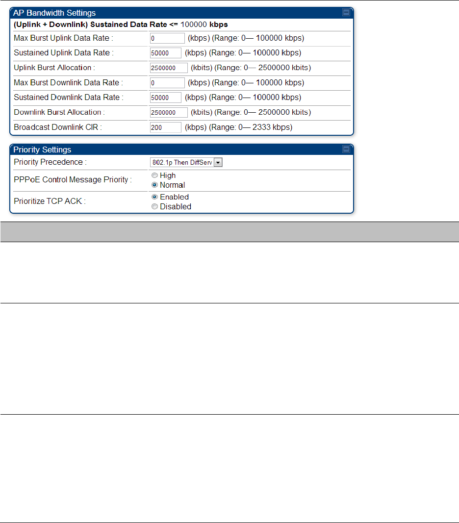
Chapter 7: Configuration
Configuring quality of service
Page 7-266
Configuring Quality of Service (QoS)
Quality of Service (QoS) page of AP
The QoS page of AP is explained in Table 156.
Table 156 QoS page attributes - AP
Attribute
Meaning
Max Burst Uplink
Data Rate
These parameters allow operators to specify the data rate at which a SM
is allowed to transmit (until burst allocation limit is reached) before
being recharged at the Sustained Uplink Data Rate with credits to transit
more. When set to 0 (default), the burst rate is unlimited.
Sustained Uplink
Data Rate
Specify the rate that each SM registered to this AP is replenished with
credits for transmission. This default imposes no restriction on the
uplink. See
Maximum Information Rate (MIR) Parameters on page 7-259
Interaction of Burst Allocation and Sustained Data Rate Settings on
page 7-261
Configuration Source on page 7-141
Uplink Burst
Allocation
Specify the maximum amount of data to allow each SM to transmit
before being recharged at the Sustained Uplink Data Rate with credits to
transmit more. See Maximum Information Rate (MIR) Parameters on
page 7-259
Interaction of Burst Allocation and Sustained Data Rate Settings on
page 7-261
Configuration Source on page 7-141

Chapter 7: Configuration
Configuring quality of service
Page 7-267
Max Burst Downlink
Data Rate
These parameters allow operators to specify the data rate at which a SM
is allowed to transmit (until burst allocation limit is reached) before
being recharged at the Sustained Downlink Data Rate with credits to
transit more. When set to 0 (default), the burst rate is unlimited.
Sustained Downlink
Data Rate
Specify the rate at which the AP is replenished with credits (tokens) for
transmission to each of the SMs in its sector. This default imposes no
restriction on the uplink. See Maximum Information Rate (MIR)
Parameters on page 7-259
Interaction of Burst Allocation and Sustained Data Rate Settings on
page 7-261
Configuration Source on page 7-141
Downlink Burst
Allocation
Specify the maximum amount of data to allow the AP to transmit to any
registered SM before the AP is replenished with transmission credits at
the Sustained Downlink Data Rate. See
Maximum Information Rate (MIR) Parameters on page 7-259
Interaction of Burst Allocation and Sustained Data Rate Settings on
page 7-261
Configuration Source on page 7-141
Broadcast Downlink
CIR
Broadcast Downlink CIR (Committed Information Rate, a minimum)
supports system designs where downlink broadcast is desired to have
higher priority than other traffic. For many other system designs,
especially typical internet access networks, leave the Broadcast
Downlink CIR at the default.
Broadcast Downlink CIR is closely related to the Broadcast Repeat Count
parameter, which is settable in the Radio tab of the Configuration page
in the AP: when the Broadcast Repeat Count is changed, the total of
available bandwidth is also changed, since packets are being sent one,
two, or three times, according to the setting in the Broadcast Repeat
Count parameter.
Priority Precedence
Allows operator to decide if 802.1p or DiffServ priority bits must be used
first when making priority decisions.
PPPoE Control
Message Priority
Operators may configure the SM to utilize the high priority channel for
PPPoE control messages. Configuring the SM in this fashion can benefit
the continuity of PPPoE connections when there are issues with PPPoE
sessions being dropped in the network. This prioritization may be
configured in the DiffServ tab in the Configuration menu of the SM.
Prioritize TCP ACK
To reduce the likelihood of TCP acknowledgement packets being
dropped, set this parameter to Enabled. This can improve throughput
that the end user perceives during transient periods of congestion on the
link that is carrying acknowledgements.
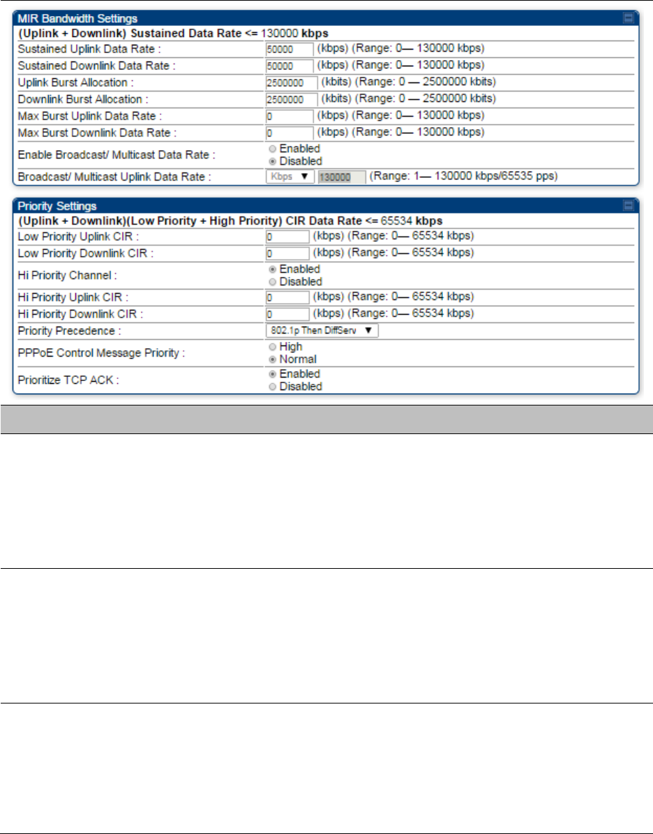
Chapter 7: Configuration
Configuring quality of service
Page 7-268
Quality of Service (QoS) page of SM
The QoS page of SM is explained in Table 157.
Table 157 QoS page attributes - SM
Attribute
Meaning
Sustained Uplink
Data Rate
Specify the rate that this SM is replenished with credits for transmission.
This default imposes no restriction on the uplink. See Maximum
Information Rate (MIR) Parameters on page 7-259
Interaction of Burst Allocation and Sustained Data Rate Settings on
page 7-261
Configuration Source on page 7-141
Sustained Downlink
Data Rate
Specify the rate at which the AP is replenished with credits (tokens) for
transmission to this SM. This default imposes no restriction on the
uplink. See Maximum Information Rate (MIR) Parameters on Page 7-259
Interaction of Burst Allocation and Sustained Data Rate Settings on
page 7-261
Configuration Source on page 7-141
Uplink Burst
Allocation
Specify the maximum amount of data to allow this SM to transmit
before being recharged at the Sustained Uplink Data Rate with credits to
transmit more. See Maximum Information Rate (MIR) Parameters on
page 7-259
Interaction of Burst Allocation and Sustained Data Rate Settings on
page 7-261

Chapter 7: Configuration
Configuring quality of service
Page 7-269
Configuration Source on page 7-141
Downlink Burst
Allocation
Specify the maximum amount of data to allow the AP to transmit to this
SM before the AP is replenished at the Sustained Downlink Data Rate
with transmission credits. See Maximum Information Rate (MIR)
Parameters on page 7-259
Interaction of Burst Allocation and Sustained Data Rate Settings on
page 7-261
Configuration Source on page 7-141
Max Burst Uplink
Data Rate
These parameters allow operators to specify the data rate at which a SM
is allowed to transmit (until burst allocation limit is reached) before
being recharged at the Sustained Uplink Data Rate with credits to transit
more. When set to 0 (default), the burst rate is unlimited.
Max Burst Downlink
Data Rate
These parameters allow operators to specify the data rate at which a SM
is allowed to transmit (until burst allocation limit is reached) before
being recharged at the Sustained Downlink Data Rate with credits to
transit more. When set to 0 (default), the burst rate is unlimited.
Enable Broadcast /
Multicast Data Rate
This parameter allows the operator to specify if Broadcast and Multicast
data is rate-limited. This data rate can be entered in Kbps or PPS
(Packets Per Second).
Broadcast / Multicast
Data Rate
This parameter allows the operator to specify a data rate at which
Broadcast and Multicast traffic is sent via the radio link.
Low Priority Uplink
CIR
This field indicates the minimum rate at which low priority traffic is sent
over the uplink (unless CIR is oversubscribed or RF link quality is
degraded).
Committed Information Rate (CIR) on page 7-260
Setting the Configuration Source on page 7-264
Low Priority
Downlink CIR
This field indicates the minimum rate at which low priority traffic is sent
over the downlink (unless CIR is oversubscribed or RF link quality is
degraded).
Committed Information Rate (CIR) on page 7-260
Setting the Configuration Source on page 7-264
Hi Priority Channel
See
High-priority Bandwidth on page 7-261
Configuration Source on page 7-141
Hi Priority Uplink CIR
This field indicates the minimum rate at which high priority traffic is sent
over the uplink (unless CIR is oversubscribed or RF link quality is
degraded).
Committed Information Rate (CIR) on page 7-260
Setting the Configuration Source on page 7-264
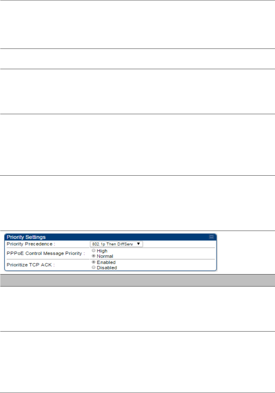
Chapter 7: Configuration
Configuring quality of service
Page 7-270
Hi Priority Downlink
CIR
This field indicates the minimum rate at which high priority traffic is sent
over the downlink (unless CIR is oversubscribed or RF link quality is
degraded).
Committed Information Rate (CIR) on page 7-260
Setting the Configuration Source on page 7-264
Priority Precedence
Allows operator to decide if 802.1p or DiffServ priority bits must be used
first when making priority decisions.
PPPoE Control
Message Priority
Operators may configure the SM to utilize the high priority channel for
PPPoE control messages. Configuring the SM in this fashion can benefit
the continuity of PPPoE connections when there are issues with PPPoE
sessions being dropped in the network. This prioritization may be
configured in the DiffServ tab in the Configuration menu of the SM.
Prioritize TCP ACK
To reduce the likelihood of TCP acknowledgement packets being
dropped, set this parameter to Enabled. This can improve throughput
that the end user perceives during transient periods of congestion on the
link that is carrying acknowledgements. This parameter, when enabled,
can be particularly useful when running bi-direction FTP sessions over
the link. If a link is primarily used for video surveillance, it is
recommended to configure this parameter to Disabled.
Quality of Service (QoS) page of BHM
The QoS page of BHM is explained in Table 158.
Table 158 QoS page attributes - BHM
Attribute
Meaning
PPPoE Control
Message Priority
Operators may configure the BHM to utilize the high priority channel for
PPPoE control messages. Configuring the BHM in this fashion can
benefit the continuity of PPPoE connections when there are issues with
PPPoE sessions being dropped in the network. This prioritization may be
configured in the DiffServ tab in the Configuration menu of the BHS.
Prioritize TCP ACK
To reduce the likelihood of TCP acknowledgement packets being
dropped, set this parameter to Enabled. This can improve throughput
that the end user perceives during transient periods of congestion on the
link that is carrying acknowledgements. This parameter, when enabled,
can be particularly useful when running bi-direction FTP sessions over
the link. If a link is primarily used for video surveillance, it is
recommended to configure this parameter to Disabled.
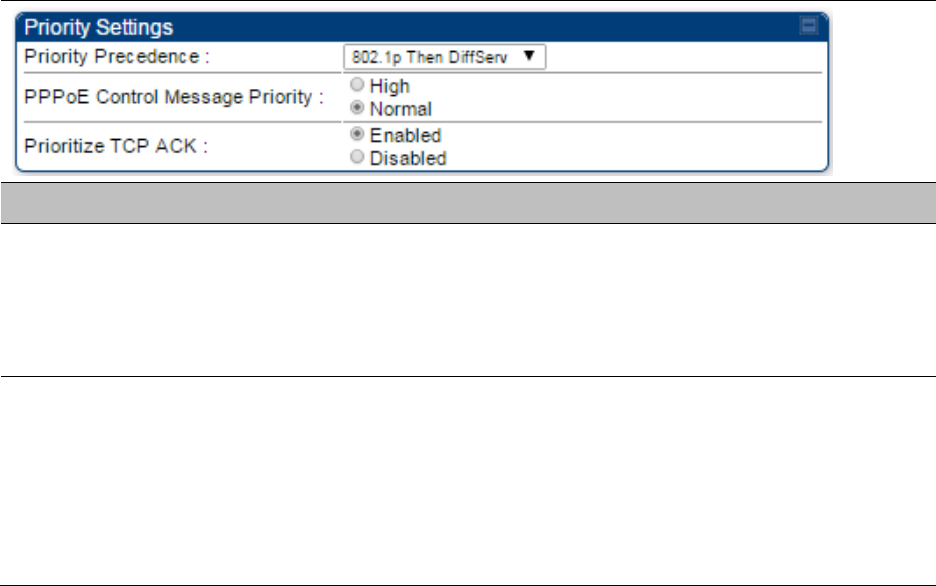
Chapter 7: Configuration
Configuring quality of service
Page 7-271
Quality of Service (QoS) page of BHS
The QoS page of BHS is explained in Table 159.
Table 159 QoS page attributes - BHS
Attribute
Meaning
PPPoE Control
Message Priority
Operators may configure the BHS to utilize the high priority channel for
PPPoE control messages. Configuring the BHS in this fashion can benefit
the continuity of PPPoE connections when there are issues with PPPoE
sessions being dropped in the network. This prioritization may be
configured in the DiffServ tab in the Configuration menu of the BHS.
Prioritize TCP ACK
To reduce the likelihood of TCP acknowledgement packets being
dropped, set this parameter to Enabled. This can improve throughput
that the end user perceives during transient periods of congestion on the
link that is carrying acknowledgements. This parameter, when enabled,
can be particularly useful when running bi-direction FTP sessions over
the link. If a link is primarily used for video surveillance, it is
recommended to configure this parameter to Disabled.
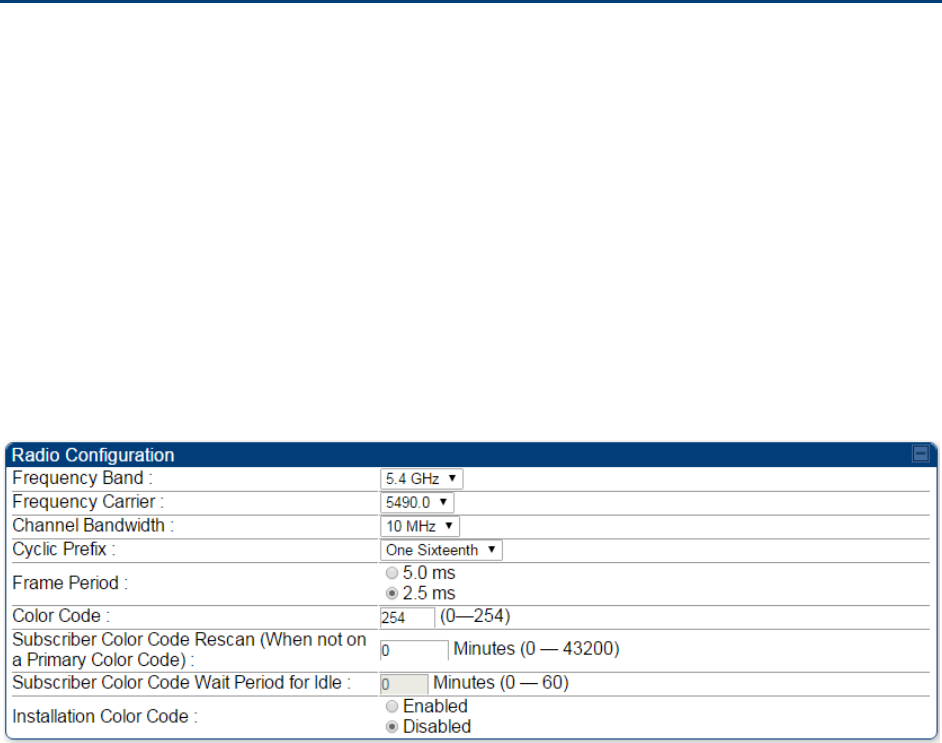
Chapter 7: Configuration
Installation Color Code
Page 7-272
Installation Color Code
With this feature enabled on the AP and SM, operators may install and remotely configure SMs
without having to configure matching color codes between the modules. While the SM is
accessible for configuration from above the AP (for remote provisioning) and below the SM (for
local site provisioning), no user data is passed over the radio link. When using the Installation
Color Code feature, ensure that the SM is configured with the factory default Color Code
configuration (Color Code 1 is “0”, Color Code 2-10 set to “0” and “Disable”). The status of the
Installation Color Code can be viewed on the AP Eval web GUI page, and when the SM is
registered using the Installation Color Code the message “SM is registered via ICC – Bridging
Disabled!” is displayed in red on every SM GUI page. The Installation Color Code parameter is
configurable without a radio reboot for both the AP and SM. If an SM is registered via Installation
Color Code and the feature is then disabled, operators will need to reboot the SM or force it to
reregister (i.e. using the Rescan APs functionality on the AP Eval page).
Figure 131 Installation Color Code of AP

Chapter 7: Configuration
Zero Touch Configuration Using DHCP Option 66
Page 7-273
Zero Touch Configuration Using DHCP Option 66
This feature allows an SM to get its configuration via DHCP option 66. This can be used for the
initial configuration of an SM as well as managing the configuration of SMs on an ongoing basis.
Here is how it works in brief:
When the SM boots up, if it is set to use DHCP client, it will send out a DHCP Discover packet
which includes a request for DHCP Option 66.
In case of a brand new SM out of the box, the DHCP Discover packet is sent out if the SM
connects to an AP using Installation Color Code (ICC), even though DHCP client is not enabled
in factory default config.
An appropriately configured DHCP server will respond with a DHCP Offer and include a URL in
response to the Option 66 request. The URL should point to the configuration file.
The device will download the configuration file and apply it. The device will reboot
automatically if needed. (Note: this requires “rebootIfRequired” flag to be added to the config
file. See Creating a Golden config file on page 7-274.
Configuration Steps
Procedure 23 Zero Touch Configuration steps
1
Create the golden config file(s)
2
Host it on an TFTP/FTP/HTTP/HTTPS server
3
Configure the DHCP server to return the URL of the golden config file in option 66
When the SM boots up, it will get the URL for the golden config from the DHCP server via option
66, download it and apply it.
If all the SMs are configured exactly the same, then you can create just new golden config file that
can be used with all SMs.
If the SMs are not configured the same, see if it is possible to group the SMs such that SMs with
the same configuration are served by the same DHCP pool. User can then create multiple golden
config files and configure the DHCP server to use the appropriate config file for each pool.
User can also create one config file per SM. This provides the most flexibility, but is practical only
if you have a software tool/script to generate the config files for each MAC address. The files
should be named <mac>.cfg where <mac> is the MAC address of the SM, and stored in the same
directory on the file server. The DHCP server should be configured to return the directory name
ending with a ‘/’ in option 66. The SM will automatically add “<mac>.cfg” to the path and get its
config file.
Chapter 7: Configuration
Zero Touch Configuration Using DHCP Option 66
Page 7-274
If some configuration is unique per SM, but rest of the configuration is common, the SMs can be
staged with the unique part, and use option 66 to manage the common part. For example, if each
SM needs to have its coordinates set, don’t include the coordinates in the golden config file.
Instead, configure the coordinates for each SM manually. Manage the rest of the configuration
using DHCP option 66.
Creating a Golden config file
The easiest way to create the golden config file is to configure an SM, export its configuration and
edit it. To export the configuration file from the GUI of the SM, go to “Configuration > Unit
Settings” tab, go to the “Download Configuration File” section and click on the “<mac>.cfg” link.
This will give you a text file in JSON format. You can edit this file in a text editor but it’s easier to
use a JSON editor like https://www.jsoneditoronline.org/.
Strip down the config file to remove sections and entries that don’t care about, and keep only the
items that require changes. If there are many required changes, it can easily get confusing. To
identify the exact items changes, first reset the SM to factory default, export the config file, make
the necessary changes, export a second config file, then use a tool like WinMerge
(http://winmerge.org/) to identify the differences.
The config file contains the following informational entries at the top level.
"cfgUtcTimestamp": "cfgUtcTimestamp",
"swVersion": "CANOPY 13.3 (Build 15) SM-AES",
"cfgFileString": "Canopy configuration file",
"srcMacAddress": "0a-00-3e-a2-c2-74",
"deviceType": "5.4/5.7GHz MIMO OFDM - Subscriber Module",
"cfgFileVersion": "1.0"
The “cfgUtcTimestamp”, “swVersion”, “srcMacAddress” and “deviceType” lines can be deleted.
Do not delete the “cfgFileString” and “cfgFileVersion” entries.
Next, create an object named “configFileParameters” at the top level. Under that, add a parameter
called “rebootIfRequired” and set it to true. This tells the SM to reboot automatically if a reboot is
needed to apply the new configuration.
A sample configuration file that has been edited for use via DHCP option 66 is given below.
{
"userParameters": {
"smNetworkConfig": {
"networkAccess": 1
},
"location": {
"siteName": "Test site"
},
"smRadioConfig": {
Chapter 7: Configuration
Zero Touch Configuration Using DHCP Option 66
Page 7-275
"frequencyScanList": [
5475000,
5480000
],
"colorCodeList": [
{
"colorCode": 42,
"priority": 1
}
]
},
"networkConfig": {
"lanDhcpState": 1
}
},
"cfgFileVersion": "1.0",
"cfgFileString": "Canopy configuration file",
"configFileParameters": {
"rebootIfRequired": true
}
}
When configuration is imported, only the items that exist in the configuration file are modified.
Parameters that are not in the imported file are not changed. If user wish to revert those settings to
their factory default values, please add a “setToDefaults” item under “configFileParameters”
section with a value of true.
"cfgFileVersion": "1.0",
"cfgFileString": "Canopy configuration file",
"configFileParameters": {
"rebootIfRequired": true,
"setToDefaults": true
}
In case, the SM needs to fetch the configuration file on each boot up even when not connecting to
AP via ICC, set “Network Accessibility” to “Public” and “DHCP State” to “Enabled” in the
“Configuration > IP” page before exporting the configuration.
Hosting the config file
Copy the golden configuration file to an FTP, TFTP, HTTP or HTTPS server. This location can be
password protected; you just have to include the user name and password in the URL.
DHCP server configuration
Configure DHCP server to return the full URL to the golden config file as the value of DHCP option
66.
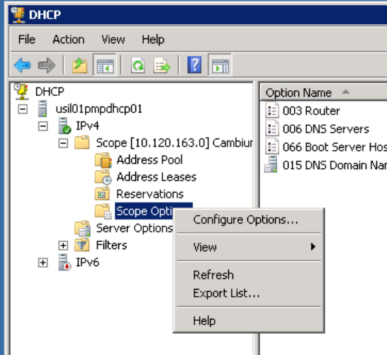
Chapter 7: Configuration
Zero Touch Configuration Using DHCP Option 66
Page 7-276
The following example explains how to make the change for Windows Server 2008. Adapt it to
your specific DHCP server.
Procedure 24 DHCP server configuration
1
Click “Start > Administrative Tools > DHCP”
2
If you have multiple “Scopes” defined, identify the correct “Scope” that will serve IP
addresses for the SMs
3
Right click on “Scope Option” under the correct “Scope” and select “Configure
Options”
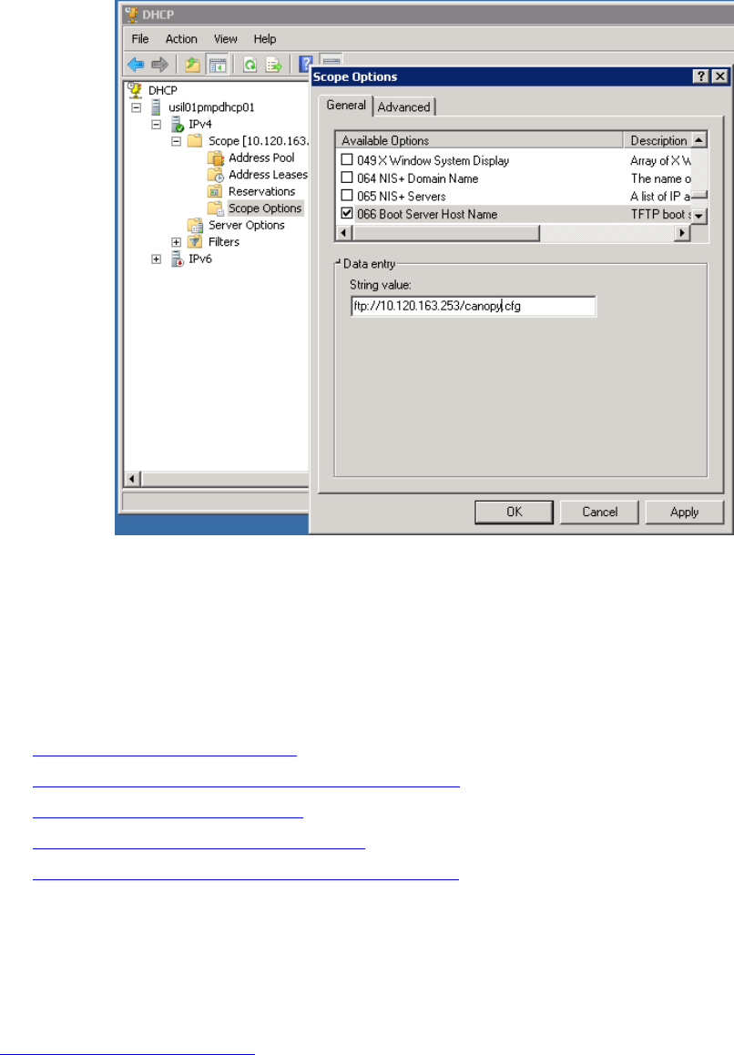
Chapter 7: Configuration
Zero Touch Configuration Using DHCP Option 66
Page 7-277
4
In the “Scope Options” dialog, scroll down to “066 Boot Server Host Name”, select the
checkbox and enter the full URL to the golden config file as the “String value”. Then
click “OK”.
5
In the DHCP snap-in window, right click and “Refresh” to see the DHCP option 66 in the
list of DHCP options
Supported URL Formats
FTP, TFTP, HTTP and HTTPS URLs are supported. Some examples are given below.
ftp://10.120.163.253/canopy.cfg
ftp://admin:admin123@10.120.163.253/canopy.cfg (login as admin with password admin123)
tftp://10.120.163.253/canopy.cfg
http://10.120.163.253/golden-config.cfg
https://10.120.163.253/smconfig/golden-config.cfg
User can also specify the URL pointing to a directory and not a specific file. Terminate the URL
with a ‘/’ to indicate that it is a directory and not a file. Use this format when each SM has its own
individual config file. The directory should contain files named “<mac>.cfg”, one for each SM.
For example:
ftp://10.120.163.253/smconfig/
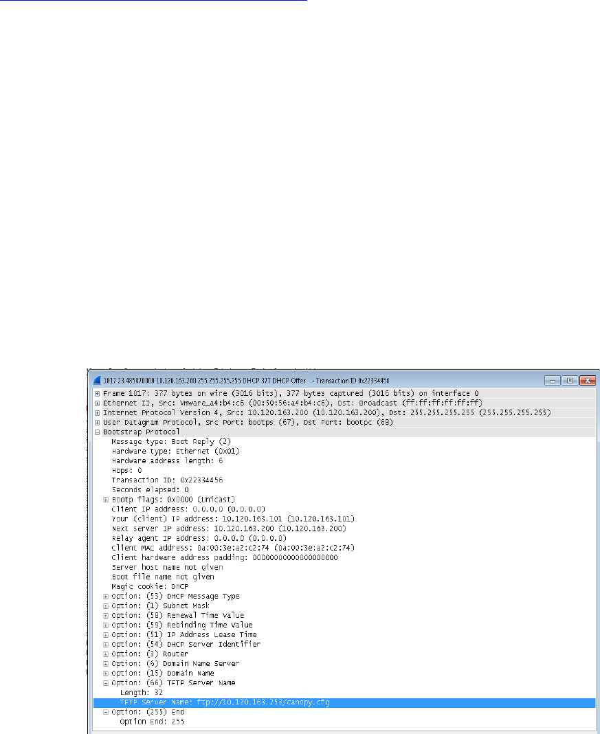
Chapter 7: Configuration
Zero Touch Configuration Using DHCP Option 66
Page 7-278
In this case, the SM will append “<mac>.cfg” to the path and try to get that file. For example, if the
SM’s MAC address is 0a-00-3e-a2-c2-74, it will request for
ftp://10.120.163.253/smconfig/0a003ea2c274.cfg. This mechanism can be used to serve individual
config file for each SM.
Troubleshooting
1
Ensure that te SM is running 13.3 or newer version of software.
2
If the SM has factory default config, confirm ICC is enabled on the AP, so the SM can
connect to it.
3
If the SM is connecting to the AP using a color code other than ICC, make sure the SM
has “Network Accessibility” set to “Public” and “DHCP State” set to “Enabled” in the
“Configuration > IP” page.
4
Make sure the golden config file does not turn off “Network Accessibility” or “DHCP
State”. If it does, the SM will no longer request the config file when it is rebooted.
5
Check the event log of the SM to see the status of the configuration file import
including any errors that prevented it from importing the file.
6
Capture the DHCP Offer packet from the DHCP server to the SM and verify that Option
66 has the expected URL.
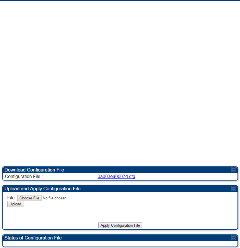
Chapter 7: Configuration
Configuring Radio via config file
Page 7-279
Configuring Radio via config file
The PMP/PTP 450 platform supports export and import of a configuration file from the AP or SM as
a text file. The configuration file is in JSON format.
To export or import the configuration file, the logged in user needs to be an ADMINISTRATOR and
it must not be a “read-only” account.
The exported configuration file contains the complete configuration including all the default
values. To keep a backup of the current configuration, the file can be saved as-is and imported
later.
While importing a configuration file, it can be either imported the full configuration or a sparse
configuration containing only the items that need to be changed. If a sparse configuration file is
imported, only the items in the file will be imported. Other configuration will remain unchanged.
There could also be used a special flag in the configuration file to tell the device to apply the
configuration starting from factory default (Refer Special Headers for configuration file on page 7-
280).
Import and Export of config file
The config file import and export is supported in Configuration > Unit Settings page. The
procedure for importing and exporting config file is explained below.
Figure 132 Configuration File upload and download page
The DHCP server configuration procedure is as follows:
Procedure 25 DHCP server configuration
1
Login to the GUI and go to Configuration > Unit Settings.
2
Under Download Configuration File tab, click on the “<mac>.cfg” link, where <mac> is
the MAC address of the device (for example, “01003ea2c274.cfg”).
3
Save the file to the local disk.
The below procedure is to be followed for Importing a config file
Chapter 7: Configuration
Configuring Radio via config file
Page 7-280
Procedure 26 Import the configuration from the GUI
1
Login to the GUI and go to Configuration → Unit Settings.
2
Click on “Browse” button under “Upload and Apply Configuration File” tab and select
the configuration file from disk.
3
Click “Upload” followed by “Apply Configuration File” button click.
4
The “Status of Configuration File” section will show the results of the upload.
5
Review it to make sure there are no errors. Then click on “Reboot” to reboot with the
imported configuration
The special headers for config file is explained below:
Procedure 27 Special Headers for configuration file
1
A "configFileParameters" section can be added to the header to control the behaviour
of the device when importing configuration.
2
The "setToDefaults" when set to "true" tell the device to reset to factory default
configuration and apply the configuration in the file on top of that. So any attribute not
in the configuration file will be set to its factory default value. By default, the
configuration in the file is merged with the existing configuration on the device.
The "rebootIfRequired" flag when set to "true" tell the device to reboot automatically if
needed to apply the configuration change. By default, the device will not reboot
automatically.
{
"cfgFileString": "Canopy configuration file",
"cfgFileVersion": "1.0",
"configFileParameters": {
"setToDefaults":true,
"rebootIfRequired":true,
}
}

Chapter 7: Configuration
Configuring a RADIUS server
Page 7-281
Configuring a RADIUS server
Configuring a RADIUS server in a PMP 450 platform network is optional, but can provide added
security, increase ease of network management and provide usage-based billing data.
Understanding RADIUS for
PMP 450 platform
PMP 450 platform modules include support for the RADIUS (Remote Authentication Dial In User
Service)
protocol supporting Authentication and Accounting.
RADIUS
Functions
RADIUS protocol support provides the
following
functions:
SM Authentication allows only known SMs onto the network (blocking
“rogue”
SMs), and
can be configured to ensure SMs are connecting to a known
network
(preventing SMs from
connecting to “rogue” APs). RADIUS authentication is
used
for SMs,
but
is not used for APs.
SM Configuration: Configures authenticated SMs with MIR (Maximum Information Rate), CIR
(Committed Information Rate), High Priority, and VLAN (Virtual LAN) parameters from the
RADIUS server when a SM registers to an AP.
SM Accounting provides support for RADIUS accounting messages for usage-based billing.
This accounting includes indications for subscriber session establishment, subscriber session
disconnection, and bandwidth usage per session for each SM that connects to the AP.
Centralized AP and SM user name and password management allows AP
and
SM
usernames and access levels (Administrator, Installer, Technician) to
be
centrally
administered in the RADIUS server instead of on each radio and tracks
access
events
(logon/logoff) for each username on the RADIUS server. This accounting does not track and
report
specific configuration actions performed on radios or pull statistics such as
bit
counts
from the radios. Such functions require an Element Management
System
(EMS) such as
Cambium Networks Wireless Manager. This accounting is
not
the ability to perform
accounting functions on the subscriber/end
user/customer
account.
Framed IP
allows o
perators to use a RADIUS server to assign management IP addressing to
SM modules (framed IP address).
Tested RADIUS Servers
The Canopy RADIUS implementation has been tested and is supported
on
FreeRADIUS, Version
2.1.8
Aradial RADIUS, Version
5.1.12
Microsoft RADIUS (Windows Server 2012 R2 version)
Cisco ACS, Version 5.7.0.15

Chapter 7: Configuration
Configuring a RADIUS server
Page 7-282
Note
Aradial 5.3 has a bug that prevents “remote device login”, so doesn’t support the user
name and password management feature.
Choosing Authentication Mode and Configuring for
Authentication Servers - AP
On the AP’s Configuration > Security tab, select the RADIUS AAA Authentication Mode. The
following describes the
other
Authentication Mode options for reference, and then the RADIUS
AAA
option.
Disabled
: Requires no authentication. Any SM (except a SM that itself has been configured
to
require
RADIUS authentication by enabling Enforce Authentication as described below) is
allowed to
register
to the
AP.
Authentication Server: Authentication Server in this instance refers to Wireless Manager in
BAM-only mode. Authentication is
required
for a SM to register to the AP. Only SMs listed
by MAC address in the Wireless Manager database is
allowed to register to the
AP.
AP Pre-Shared
Key
: Canopy offers a pre-shared key authentication option. In this case, an
identical key
must
be entered in the Authentication Key field on the AP’s Configuration >
Security tab and in the Authentication Key field on each desired SM’s Configuration >
Security
tab.
RADIUS
AAA
: To support RADIUS authentication of SMs, on the AP’s Configuration >
Security tab
select
RADIUS AAA. Only properly configured SMs with a valid certificate is
allowed to
register
to the
AP.
When RADIUS AAA is selected, up to 3 Authentication Server (RADIUS Server)
IP
addresses
and
Shared Secrets can be configured. The IP address(s) configured here
must
match the IP
address(s) of the RADIUS server(s). The shared secret(s) configured here
must
match the shared
secret(s) configured in the RADIUS server(s). Servers 2 and 3 are meant
for
backup and
reliability, not splitting the database. If Server 1 doesn’t respond, Server 2 is
tried,
and then
server
3. If Server 1 rejects authentication, the SM is denied entry to the network, and does
not
progress trying the other
servers.
The default IP address is 0.0.0.0.
The
default Shared Secret is “CanopySharedSecret”. The
Shared Secret can be up to 32
ASCII
characters (no diacritical marks or ligatures, for
example).
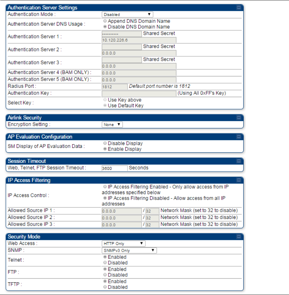
Chapter 7: Configuration
Configuring a RADIUS server
Page 7-283
Table 160 Security tab attributes

Chapter 7: Configuration
Configuring a RADIUS server
Page 7-284
Attribute
Meaning
Authentication Mode
Operators may use this field to select the following authentication
modes:
Disabled—the AP requires no SMs to authenticate.
Authentication Server —the AP requires any SM that attempts
registration to be authenticated in Wireless Manager before registration.
AP PreShared Key - The AP acts as the authentication server to its SMs
and will make use of a user-configurable pre-shared authentication key.
The operator enters this key on both the AP and all SMs desired to
register to that AP. There is also an option of leaving the AP and SMs at
their default setting of using the “Default Key”. Due to the nature of the
authentication operation, if you want to set a specific authentication key,
then you MUST configure the key on all of the SMs and reboot them
BEFORE enabling the key and option on the AP. Otherwise, if you
configure the AP first, none of the SMs is able to register.
RADIUS AAA - When RADIUS AAA is selected, up to 3 Authentication
Server (RADIUS Server) IP addresses and Shared Secrets can be
configured. The IP address(s) configured here must match the IP
address(s) of the RADIUS server(s). The shared secret(s) configured here
must match the shared secret(s) configured in the RADIUS server(s).
Servers 2 and 3 are meant for backup and reliability, not for splitting the
database. If Server 1 doesn’t respond, Server 2 is tried, and then server
3. If Server 1 rejects authentication, the SM is denied entry to the
network and does not progress trying the other servers.
Authentication
Server DNS Usage
The management DNS domain name may be toggled such that the
name of the authentication server only needs to be specified and the
DNS domain name is automatically appended to that name.
Authentication
Server 1
Enter the IP address or server name of the authentication server
(RADIUS or WM) and the Shared Secret configured in the authentication
server. When Authentication Mode RADIUS AAA is selected, the default
value of Shared Secret is “CanopySharedSecret”. The Shared Secret
may consist of up to 32 ASCII characters.
Authentication
Server 2
Authentication
Server 3
Authentication
Server 4 (BAM Only)
Authentication
Server 5 (BAM Only)
Radius Port
This field allows the operator to configure a custom port for RADIUS
server communication. The default value is 1812.
Authentication Key
The authentication key is a 32-character hexadecimal string used when
Authentication Mode is set to AP Pre-Shared Key. By default, this key is
set to 0xFFFFFFFFFFFFFFFFFFFFFFFFFFFFFFFF.

Chapter 7: Configuration
Configuring a RADIUS server
Page 7-285
Selection Key
This option allows operators to choose which authentication key is used:
Use Key above means that the key specified in Authentication Key is
used for authentication
Use Default Key means that a default key (based off of the SM’s MAC
address) is used for authentication
Encryption Key
Specify the type of airlink security to apply to this AP. The encryption
setting must match the encryption setting of the SMs.
None provides no encryption on the air link.
DES (Data Encryption Standard): An over-the-air link encryption option
that uses secret 56-bit keys and 8 parity bits. DES performs a series of bit
permutations, substitutions, and recombination operations on blocks of
data. DES encryption does not affect the performance or throughput of
the system.
AES (Advanced Encryption Standard): An over-the-air link encryption
option that uses the Rijndael algorithm and 128-bit keys to establish a
higher level of security than DES. AES products are certified as
compliant with the Federal Information Processing Standards (FIPS 197)
in the U.S.A.
SM Display of AP
Evaluation Data
You can use this field to suppress the display of data about this AP on
the AP Evaluation tab of the Tools page in all SMs that register.
Web, Telnet, FTP
Session Timeout
Enter the expiry in seconds for remote management sessions via HTTP,
telnet, or ftp access to the AP.
IP Access Control
You can permit access to the AP from any IP address (IP Access Filtering
Disabled) or limit it to access from only one, two, or three IP addresses
that you specify (IP Access Filtering Enabled). If you select IP Access
Filtering Enabled, then you must populate at least one of the three
Allowed Source IP parameters or have no access permitted from any IP
address
Allowed Source IP 1
If you selected IP Access Filtering Enabled for the IP Access Control
parameter, then you must populate at least one of the three Allowed
Source IP parameters or have no access permitted to the AP from any IP
address. You may populate as many as all three.
Allowed Source IP 2
If you selected IP Access Filtering Disabled for the IP Access Control
parameter, then no entries in this parameter are read, and access from
all IP addresses is permitted.
Allowed Source IP 3
Web Access
The Radio supports secured and non-secured web access protocols.
Select suitable web access from drop down list:
HTTP Only – provides non-secured web access. The radio to be
accessed via http://<IP of Radio>.
HTTPS Only – provides a secured web access. The radio to be
accessed via https1://<IP of Radio>.

Chapter 7: Configuration
Configuring a RADIUS server
Page 7-286
HTTP and HTTPS – If enabled, the radio can be accessed via both
http and https.
SNMP
This option allows to configure SNMP agent communication version. It
can be selected from drop down list :
SNMPv2c Only – Enables SNMP v2 community protocol.
SNMPv3 Only – Enables SNMP v3 protocol. It is secured
communication protocol.
SNMPv2c and SNMPv3 – It enables both the protocols.
Telnet
This option allows to Enable and Disable Telnet access to the Radio.
FTP
This option allows to Enable and Disable FTP access to the Radio.
TFTP
This option allows to Enable and Disable TFTP access to the Radio.
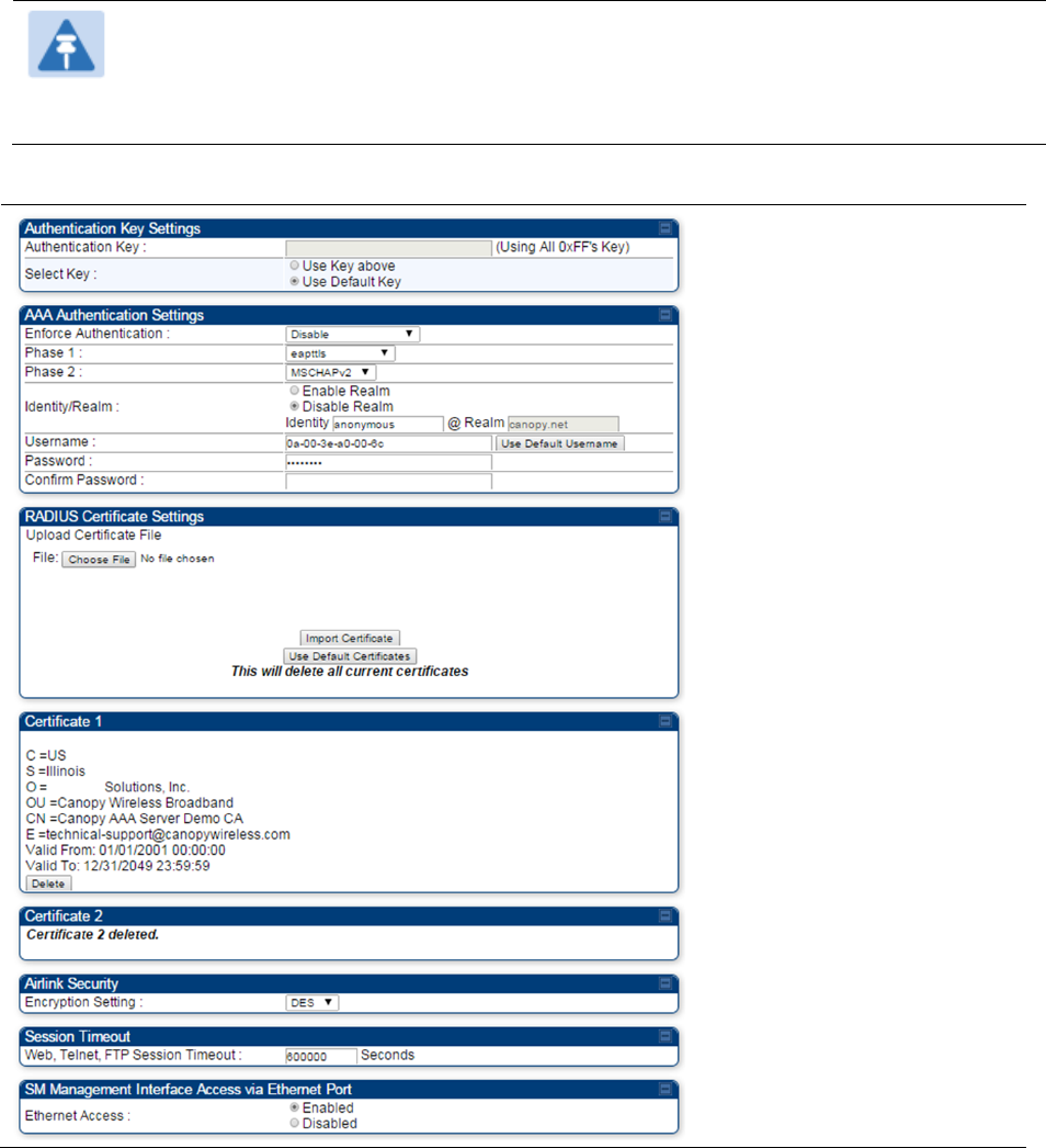
Chapter 7: Configuration
Configuring a RADIUS server
Page 7-287
SM Authentication Mode – Require RADIUS or Follow
AP
If it is desired that a SM will only authenticate to an AP that is using RADIUS, on the
SM’s
Configuration Security tab set Enforce Authentication to AAA. With this enabled, SM
does
not
register to an AP that has any Authentication Mode other than RADIUS AAA
selected
.
If it is desired that a SM use the authentication method configured on the AP it is
registering
to,
set Enforce Authentication to Disabled. With Enforce Authentication disabled, a SM will
attempt to register
using
whichever Authentication Mode is configured on the AP it is attempting
to register
to.
Note
Having SMs to use RADIUS by enabling Enforce Authentication avoids the security
issue of SMs possibly registering to “rogue” APs, which have authentication
disabled.
Table 161 SM Security tab attributes
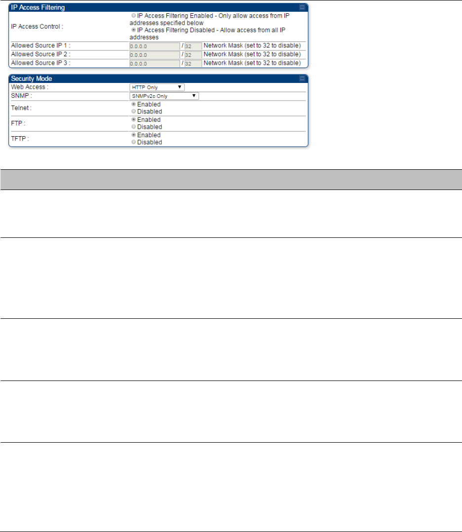
Chapter 7: Configuration
Configuring a RADIUS server
Page 7-288
Attribute
Meaning
Authentication Key
The authentication key is a 32-character hexadecimal string used when
Authentication Mode is set to AP PreShared Key. By default, this key is
set to 0xFFFFFFFFFFFFFFFFFFFFFFFFFFFFFFFF.
Select Key
This option allows operators to choose which authentication key is used:
Use Key above means that the key specified in Authentication Key is
used for authentication
Use Default Key means that a default key (based off of the SM’s MAC
address) is used for authentication
Enforce
Authentication
The SM may enforce authentication types of AAA and AP Pre-
sharedKey. The SM will not finish the registration process if the AP is not
using the configured authentication method (and the SM locks out the
AP for 15 minutes). Enforce Authentication default setting is Disable.
Phase 1
The protocols supported for the Phase 1 (Outside Identity) phase of
authentication are
EAPTTLS (Extensible Authentication Protocol
Tunneled Transport Layer
Security) or MSCHAPv2 (Microsoft
Challenge-Handshake Authentication Protocol version 2).
Phase 2
Select the desired Phase 2 (Inside Identity) authentication protocol from
the Phase 2 options of PAP (Password Authentication Protocol), CHAP
(Challenge Handshake
Authentication
Protocol), and MSCHAP
(Microsoft’s version of CHAP, version 2 is used). The protocol
must
be
consistent with the authentication protocol configured on the RADIUS
server.

Chapter 7: Configuration
Configuring a RADIUS server
Page 7-289
Identity/Realm
If Realms are being used, select Enable Realm and configure an outer
identity in the
Identity
field and a Realm in the Realm field. These must
match the Phase 1/Outer Identity and
Realm
configured in the RADIUS
server. The default Identity is “anonymous”. The Identity can be
up
to
128 non-special (no diacritical markings) alphanumeric characters. The
default Realm
is
“canopy.net”. The Realm can also be up to 128 non-
special alphanumeric
characters.
Configure an outer Identity in the Username field. This must match the
Phase
1/Outer
Identity username configured in the RADIUS server. The
default Phase 1/Outer
Identity
Username is “anonymous”. The
Username can be up to 128 non-special (no
diacritical
markings)
alphanumeric
characters.
Username
Enter a Username for the SM. This must match the username
configured for the SM on
the
RADIUS server. The default Username is
the SM’s MAC address. The Username can be up
to
128 non-special
(no diacritical markings) alphanumeric
characters.
Password
Enter the desired password for the SM in the Password and Confirm
Password fields.
The
Password must match the password configured
for the SM on the RADIUS server.
The
default Password is “password”.
The Password can be up to 128 non-special (no
diacritical
markings)
alphanumeric
characters.
Confirm Password
Upload Certificate
File
To upload a certificate manually to a SM, first load it in a known place
on your PC
or
network
drive, then click on a Delete button on one of
the Certificate description blocks to delete a certificate to provide space
for your certificate. Click on Choose File, browse to
the
location of the
certificate, and click the Import Certificate button, and then reboot the
radio to use the new certificate.
When a certificate is in use, after the SM successfully registers to an
AP, an indication of In
Use
will appear in the description block of the
certificate being
used.
The public certificates installed on the SMs are used with the private
certificate on the
RADIUS
server to provide a public/private key
encryption
system.
Up to 2 certificates can be resident on a SM. An installed certificate can
be deleted
by
clicking the Delete button in the certificate’s description
block on the Configuration >
Security
tab. To restore the 2 default
certificates, click the Use Default Certificates button in
the
RADIUS
Certificate Settings parameter block and reboot the
radio.

Chapter 7: Configuration
Configuring a RADIUS server
Page 7-290
Encryption Setting
Specify the type of airlink security to apply to this AP. The encryption
setting must match the encryption setting of the SMs.
None provides no encryption on the air link.
DES (Data Encryption Standard): An over-the-air link encryption option
that uses secret 56-bit keys and 8 parity bits. DES performs a series of bit
permutations, substitutions, and recombination operations on blocks of
data. DES encryption does not affect the performance or throughput of
the system.
AES (Advanced Encryption Standard): An over-the-air link encryption
option that uses the Rijndael algorithm and 128-bit keys to establish a
higher level of security than DES. AES products are certified as
compliant with the Federal Information Processing Standards (FIPS 197)
in the U.S.A.
Web, Telnet, FTP
Session Timeout
Enter the expiry in seconds for remote management sessions via HTTP,
telnet or ftp access to the AP.
Ethernet Access
If you want to prevent any device that is connected to the Ethernet port
of the SM from accessing the management interface of the SM, select
Ethernet Access Disabled. This selection disables access through this
port to via HTTP (the GUI), SNMP, telnet, FTP, and TFTP. With this
selection, management access is available through only the RF interface
via either an IP address (if Network Accessibility is set to Public on the
SM) or the Session Status or Remote Subscribers tab of the AP.. See IP
Access Control below.
If you want to allow management access through the Ethernet port,
select Ethernet Access Enabled. This is the factory default setting for this
parameter.
IP Access Control
You can permit access to the AP from any IP address (IP Access Filtering
Disabled) or limit it to access from only one, two, or three IP addresses
that you specify (IP Access Filtering Enabled). If you select IP Access
Filtering Enabled, then you must populate at least one of the three
Allowed Source IP parameters or have no access permitted from any IP
address
Allowed Source IP 1
If you selected IP Access Filtering Enabled for the IP Access Control
parameter, then you must populate at least one of the three Allowed
Source IP parameters or have no access permitted to the AP from any IP
address. You may populate as many as all three.
If you selected IP Access Filtering Disabled for the IP Access Control
parameter, then no entries in this parameter are read, and access from
all IP addresses is permitted.
Allowed Source IP 2
Allowed Source IP 3
Web Access
The Radio supports secured and non-secured web access protocols.
Select suitable web access from drop down list:
HTTP Only – provides non-secured web access. The radio to be
accessed via http://<IP of Radio>.

Chapter 7: Configuration
Configuring a RADIUS server
Page 7-291
HTTPS Only – provides a secured web access. The radio to be
accessed via https://<IP of Radio>.
HTTP and HTTPS – If enabled, the radio can be accessed via both
http and https.
SNMP
This option allows to configure SNMP agent communication version. It
can be selected from drop down list :
SNMPv2c Only – Enables SNMP v2 community protocol.
SNMPv3 Only – Enables SNMP v3 protocol. It is secured
communication protocol.
SNMPv2c and SNMPv3 – It enables both the protocols.
Telnet
This option allows to Enable and Disable Telnet access to the Radio.
FTP
This option allows to Enable and Disable FTP access to the Radio.
TFTP
This option allows to Enable and Disable TFTP access to the Radio.
SM - Phase 1 (Outside Identity) parameters and
settings
The protocols supported for the Phase 1 (Outside Identity) phase of authentication
are
eapttls (Extensible Authentication Protocol Tunneled Transport Layer
Security) and
eapMSChapV2
(Extensible Authentication Protocol – Microsoft Challenge-Handshake
Authentication Protocol).
Configure an outer Identity in the Username field. This must match the Phase
1/Outer
Identity
username configured in the RADIUS server. The default Phase 1/Outer
Identity
Username is
“anonymous”. The Username can be up to 128 non-special (no
diacritical
markings)
alphanumeric
characters.
If Realms are being used in the RADIUS system (eapttls only), select
Enable Realm and configure an outer identity in the
Identity
field and a Realm in the Realm field.
These must match the Phase 1/Outer Identity and
Realm
configured in the RADIUS server. The
default Identity is “anonymous”. The Identity can be
up
to
128 non-special (no diacritical markings)
alphanumeric characters. The default Realm
is
“canopy.net”. The Realm can also be up to 128 non-
special alphanumeric
characters.
SM - Phase 2 (Inside Identity) parameters and
settings
If using eapttls for Phase 1 authentication, select the desired Phase 2 (Inside Identity)
authentication protocol from the Phase 2 options of PAP (Password Authentication Protocol),
CHAP (Challenge Handshake
Authentication
Protocol), and MSCHAPv2 (Microsoft’s version of
CHAP). The protocol
must
be
consistent with the authentication protocol configured on the
RADIUS
server.
Enter a Username for the SM. This must match the username configured for the
SM on
the
RADIUS server. The default Username is the SM’s MAC address. The Username can
be up
to
128 non-special (no diacritical markings) alphanumeric
characters.
Enter the desired password for the SM in the Password and Confirm Password fields.
The
Password must match the password configured for the SM on the RADIUS server.
The
default
Password is “password”. The Password can be up to 128 non-special (no
diacritical
markings)
alphanumeric
characters.

Chapter 7: Configuration
Configuring a RADIUS server
Page 7-292
Handling Certificates
Managing SM Certificates via the SM GUI
The default public Canopy certificates are loaded into SMs upon factory software installation.
The default certificates are not secure and are intended for
use
during lab and field trials as part
of gaining experience with the RADIUS functionalities or as
an
option during debug. For secure
operation, an operator will want to create or procure their
own
certificates. Resetting a SM to its
factory defaults will remove the current certificates and restore the default certificates.
Up to two certificates can be resident on a SM. An installed certificate can be deleted
by
clicking
the Delete button in the certificate’s description block on the Configuration >
Security
tab. To
restore the 2 default certificates, click the Use Default Certificates button in
the
RADIUS
Certificate Settings parameter block and reboot the
radio.
To upload a certificate manually to a SM, first load it in a known place on your PC
or
network
drive, then click on a Delete button on one of the Certificate description blocks to delete a
certificate to provide space for your certificate. Click on Choose File, browse to
the
location of the
certificate, and click the Import Certificate button, and then reboot the radio to use the new
certificate.
When a certificate is in use, after the SM successfully registers to an AP, an indication of In
Use
will appear in the description block of the certificate being
used.
The public certificates installed on the SMs are used with the private certificate on the
RADIUS
server to provide a public/private key encryption
system.
Note
Root certificates of more than one level (Example - a certificate from someone who
received their CA from Verisign) fails. Certificates must be either root or self-signed.
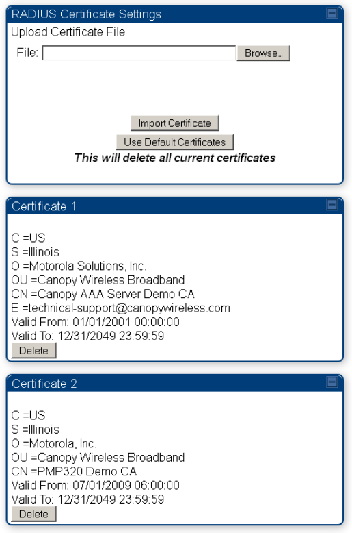
Chapter 7: Configuration
Configuring a RADIUS server
Page 7-293
Figure 133 SM Certificate Management
Configuring RADIUS servers for SM authentication
Your RADIUS server must be configured to use the
following:
EAPTTLS or MSCHAPv2 as the Phase 1/Outer Identity
protocol.
If Enable Realm is selected on the SM’s Configuration > Security tab, then the
same
Realm
appears there (or access to it).
The same Phase 2 (Inner Identity) protocol as configured on the SM’s
Configuration
>
Security tab under Phase 2 options.
The username and password for each SM configured on each SM’s
Configuration
> Security
tab.
An IP address and NAS shared secret that is the same as the IP address and Shared Secret
configured on the AP’s Configuration > Security tab for
that
RADIUS server.

Chapter 7: Configuration
Configuring a RADIUS server
Page 7-294
A server private certificate, server key, and CA certificate that complement
the
public
certificates distributed to the SMs, as well as the Canopy dictionary file
that
defines Vendor
Specific Attributes (VSAa). Default certificate files and
the
dictionary
file are available from
the software
site:
https://support.cambiumnetworks.com/files/pmp450 after entering your
name,
email address, and either Customer Contract Number or the MAC address of
a
module covered under the 12 month
warranty.
Optionally, operators may configure the RADIUS server response messages (Accept or Reject) so
that the user has information as to why they have been rejected. The AP displays the RADIUS
Authentication Reply message strings in the Session Status list as part of each SM’s information.
The SM will show this string (listed as Authentication Response on the SM GUI) on the main
Status page in the Subscriber Module Stats section.
Note
Aradial AAA servers only support operator-configurable Authentication Accept
responses, not Authentication Reject responses.

Chapter 7: Configuration
Configuring a RADIUS server
Page 7-295
Assigning SM management IP addressing via RADIUS
Operators may use a RADIUS AAA server to assign management IP addressing to SM modules
(framed IP address). SMs now interpret attributes Framed-IP-Address, Framed-IP-Netmask, and
Cambium-Canopy-Gateway from RADIUS. The RADIUS dictionary file has been updated to include
the Cambium-Canopy-Gateway attribute and is available on the Cambium Software Support
website.
In order for these attributes to be assigned and used by the SM, the following must be true:
The system is configured for AAA authentication
The SM is not configured for DHCP on its management interface. If DHCP is enabled and these
attributes are configured in the RADIUS server, the attributes is ignored by the SM.
The SM management interface must be configured to be publically accessible. If the SM is
configured to have local accessibility, the management interface will still be assigned the
framed addressing, and the SM iscome publicly accessible via the assigned framed IP
addressing.
When using these attributes, for the addressing to be implemented by the SM operators must
configure Framed-IP-Address in RADIUS. If Framed-IP-Address is not configured but Framed-
IP-Netmask and/or Cambium-Canopy-Gateway is configured, the attributes is ignored. In the
case where only the Framed-IP-Address is configured, Framed-IP-Netmask defaults to
255.255.0.0 (NAT disabled) / 255.255.255.0 (NAT enabled) and Cambium-Canopy-Gateway
defaults to 0.0.0.0.
Configuring RADIUS server for SM configuration
Canopy Vendor Specific Attributes (VSAs) along with VSA numbers and
other
details are listed
in Table 162. The associated SM GUI page, tab and parameter are listed to aid
cross-referencing
and understanding of the
VSAs.
A RADIUS dictionary file is available from the software
site:
https://support.cambiumnetworks.com/files/pmp450
The RADIUS dictionary file
defines
the VSAs and their values and is usually imported into the
RADIUS server as part of
server
and database
setup.

Chapter 7: Configuration
Configuring a RADIUS server
Page 7-296
Note
Beginning with System Release 12.0.2, two RADIUS dictionary files are available on
the Cambium website – “RADIUS Dictionary file – Cambium” and “RADIUS Dictionary
file – Motorola”.
In addition to a renaming of attributes, the Cambium-branded dictionary file contains
two new VSAs for controlling uplink and downlink Maximum Burst Data Rate (these
VSAs are listed below in Table 162).
If you are transitioning from the Motorola-branded dictionary file to the Cambium-
branded dictionary file, ensure that all RADIUS profiles containing Motorola-Canopy
attribute references are updated to include Cambium-Canopy attribute references (for
all applicable VSAs listed in Table 162). Also, ensure that all RADIUS configuration
files reference the new dictionary file (as an alternative, operators may rename the
Cambium-branded dictionary file to the filename currently in use by the RADIUS
server). Once the profiles are updated and the new Cambium-branded dictionary file is
installed on the RADIUS server, restart the RADIUS server to ensure that the new
VSAs and attribute names are enabled.
Table 162 RADIUS Vendor Specific Attributes (VSAs)
Name
Number
Type
Required
Value
MS-MPPE-Send-Key
*
26.311.16
-
Y
-
-
-
-
MS-MPPE-Recv-Key
*
26.311.17
-
Y
-
-
-
-
Cambium-Canopy-LPULCIR
26.161.1
integer
N
0-65535
kbps
Configuration > Quality of Service > Low Priority Uplink
CIR
0
kbps
32 bits
Cambium-Canopy-LPDLCIR
26.161.2
integer
N
0-65535
kbps
Configuration > Quality of Service > Low Priority Downlink
CIR
0
kbps
32 bits
Cambium-Canopy-HPULCIR
26.161.3
integer
N
0-65535
kbps
Configuration > Quality of Service > Hi Priority Uplink
CIR
0
kbps
32 bits
Cambium-Canopy-HPDLCIR
26.161.4
integer
N
0-65535
kbps
Configuration > Quality of Service > Hi Priority Uplink
CIR
0
kbps
32 bits
Cambium-Canopy-HPENABLE
26.161.5
integer
N
0-disable,
1-enable
Configuration > Quality of Service > Hi Priority
Channel
Enable/Disable
0
32 bits
26.161.6
integer
N
0-100000
kbps

Chapter 7: Configuration
Configuring a RADIUS server
Page 7-297
Configuration > Quality of Service > Sustained Uplink
Data
Rate
dependent
on
radio
feature
set
32 bits
Cambium-Canopy-ULBL
26.161.7
integer
N
0-2500000
kbps
Configuration > Quality of Service > Uplink Burst
Allocation
dependent
on
radio
feature
set
32 bits
Cambium-Canopy-DLBR
26.161.8
integer
N
0-100000
kbps
Configuration > Quality of Service > Sustained Downlink
Data
Rate
dependent
on
radio
feature
set
32 bits
Cambium-Canopy-DLBL
26.161.9
integer
N
0-2500000
kbps
Configuration > Quality of Service > Downlink Burst
Allocation
dependent
on
radio
feature
set
32 bits
Cambium-Canopy-
VLLEARNEN
26.161.14
integer
N
0-disable,
1-enable
Configuration > VLAN > Dynamic
Learning
1
32 bits
Cambium-Canopy-
VLFRAMES
26.161.15
integer
N
0-all, 1-tagged,
2-
untagged
Configuration > VLAN > Allow Frame
Types
0
32 bits
Cambium-Canopy-VLIDSET
26.161.16
integer
N
VLAN Membership
(1-4094)
Configuration > VLAN
Membership
0
32 bits
Cambium-Canopy-VLAGETO
26.161.20
integer
N
5 - 1440
minutes
Configuration > VLAN > VLAN Aging
Timeout
25
mins
32 bits
Cambium-Canopy-VLIGVID
26.161.21
integer
N
1 –
4094
Configuration > VLAN > Default Port
VID
1
32 bits
Cambium-Canopy-VLMGVID
26.161.22
integer
N
1 –
4094
Configuration > VLAN > Management
VID
1
32 bits
Cambium-Canopy-
VLSMMGPASS
26.161.23
integer
N
0-disable,
1-enable
Configuration > VLAN > SM Management VID
Pass-through
1
32 bits
Cambium-Canopy-BCASTMIR
26.161.24
integer
N
0-100000 kbps,
0=disabled
Configuration > Quality of Service > Broadcast/Multicast
Uplink
Data Rate
dependent
on
radio
feature
set
32 bits
Cambium-Canopy-Gateway
26.161.25
ipaddr
N
-
Configuration > IP > Gateway IP Address
0.0.0.0
-
Chapter 7: Configuration
Configuring a RADIUS server
Page 7-298
Cambium-Canopy-ULMB
26.161.26
integer
N
0-100000 kbps
Configuration > Quality of Service > Max Burst Uplink Data
Rate
0
32 bits
Cambium-Canopy-DLMB
26.161.27
integer
N
0-100000 kbps
Configuration > Quality of Service > Max Burst Downlink Data
Rate
0
32 bits
Cambium-Canopy-UserLevel
26.161.50
integer
N
1-Technician,
2-
Installer, 3-
Administrator
Account > Add User >
Level
0
32 bits
(*) Contains key for encrypting packets sent by the NAS to the remote host (for Microsoft Point-
to-Point Encryption Protocol).
Note
VSA
numbering:
26 connotes Vendor Specific Attribute, per RFC
2865
26.311 is Microsoft Vendor Code, per
IANA
Configuring RADIUS server for SM configuration using Zero
Touch feature
The RADIUS VSA (Vendor Specific Attributes) is updated for Zero Touch feature. This feature
enables the ability for a SM to get its configuration via RADIUS VSA. The RADIUS VSA is updated
for an URL which points to the configuration file of SM (see Table 162 for list of VSA).
The RADIUS will push the vendor specific attribute to SM after successful authentication. The VSA
contains URL of config file which will redirect SM to download configuration. If there is any change
in SM confirmation, the SM will reboot automatically after applying the configuration.
The RADIUS VSA attributes concerning Zero Touch are as follows:
VSA Type String
Cambium-Canopy-ConfigFileImportUrl (29) string Maximum Length 127
characters.
Cambium-Canopy-ConfigFileExportUrl (30) string Maximum Length 127
characters.
The updated RADIUS dictionary can be downloaded from below link:
https://support.cambiumnetworks.com/files/pmp450/
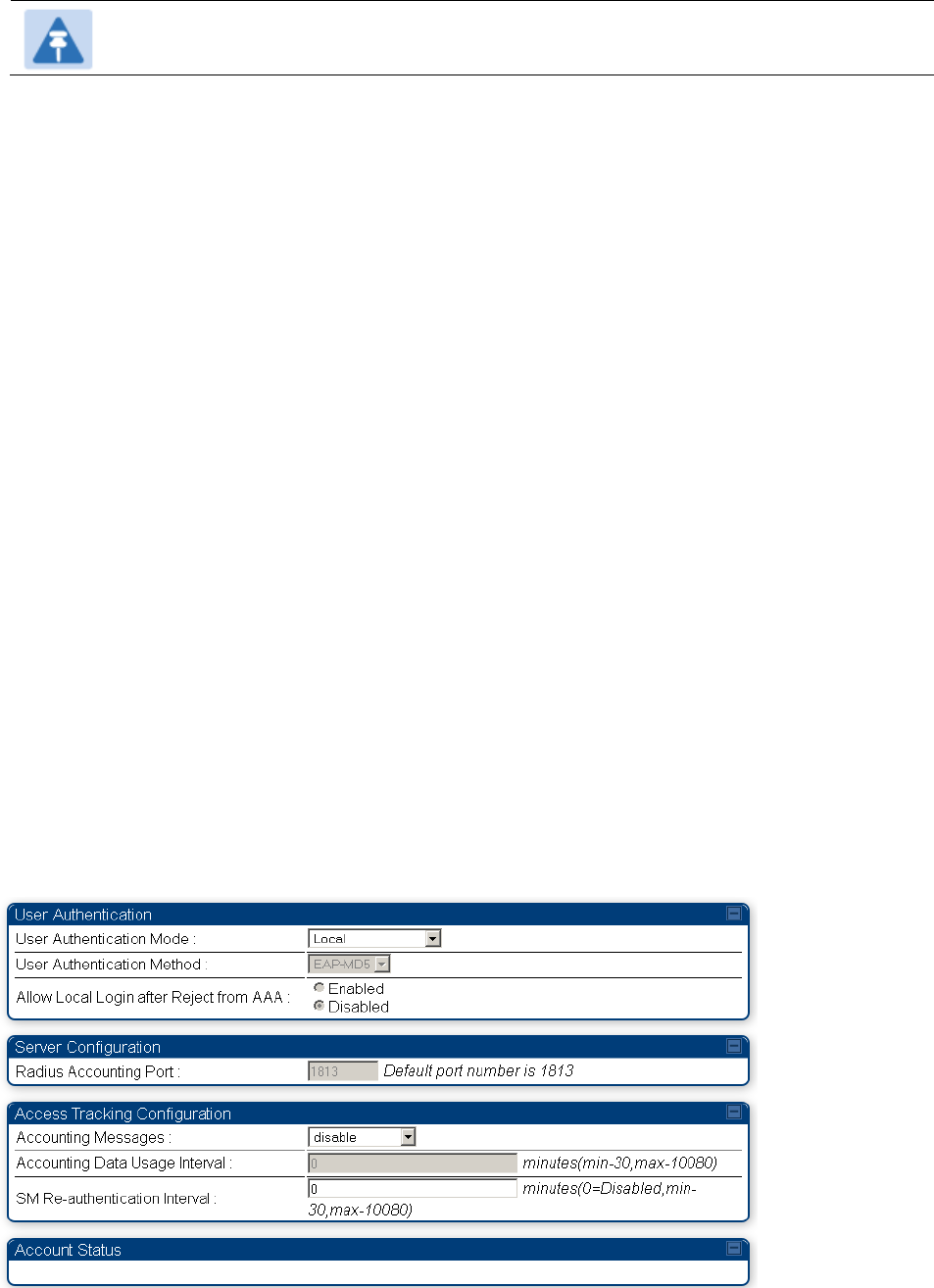
Chapter 7: Configuration
Configuring a RADIUS server
Page 7-299
Note
The feature is not applicable to the AP.
Using RADIUS for centralized AP and SM user name and
password management
AP – Technician/Installer/Administrator
Authentication
To control technician, installer, and administrator access to the AP from a centralized
RADIUS
server:
Procedure 28 Centralized user name and password management for AP
1
Set Authentication Mode on the AP’s Configuration > Security tab to RADIUS AAA
2
Set User Authentication Mode on the AP’s Account > User Authentication
tab
(the tab
only appears after the AP is set to RADIUS authentication) to
Remote
or Remote then
Local
.
Local: The local SM is checked for accounts. No centralized
RADIUS
accounting
(access control)
is
performed.
Remote: Authentication by the centralized RADIUS server
is
required to gain access
to the SM if the SM is registered to an
AP
that has RADIUS AAA Authentication
Mode selected. For up to
2
minutes a test pattern is displayed until the server
responds
or
times
out.
Remote then Local: Authentication using the centralized
RADIUS
server is
attempted. If the server sends a reject message, then
the
setting of Allow Local
Login after Reject from AAA determines
if
the local user database is checked or
not. If the configured
servers
do
not respond within 2 minutes, then the local user
database
is
used. The successful login method is displayed in the
navigation
column of the SM.
Figure 134 User Authentication and Access Tracking tab of the AP
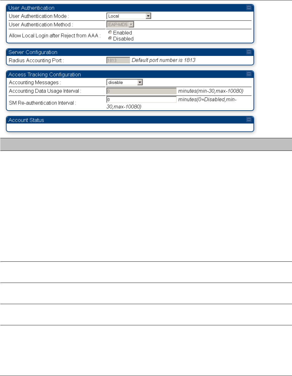
Chapter 7: Configuration
Configuring a RADIUS server
Page 7-300
Table 163 AP User Authentication and Access Tracking attributes
Attribute
Meaning
User Authentication
Mode
Local: The local SM is checked for accounts. No centralized
RADIUS
accounting (access control)
is
performed.
Remote: Authentication by the centralized RADIUS server
is
required to gain access to the AP. For up to
2
minutes a test pattern
is displayed until the server responds
or
times
out.
Remote then Local: Authentication using the centralized
RADIUS
server is attempted. If the server sends a reject message, then
the
setting of Allow Local Login after Reject from AAA determines
if
the local user database is checked or not. If the configured
servers
do
not respond within 2 minutes, then the local user database
is
used. The successful login method is displayed in the
navigation
column of the AP.
User Authentication
Method
The user authentication method employed by the radios is EAP-MD5.
Allow Local Login after
Reject from AAA
If a user authentication is rejected from the AAA server, the user is
allowed to login locally to the radio’s management interface.
Radius Accounting
Port
The destination port on the AAA server used for Radius accounting
communication.
Accounting Messages
disable – no accounting messages are sent to the RADIUS server
deviceAccess – accounting messages are sent to the RADIUS server
regarding device access (see Table 165).
dataUsage – accounting messages are sent to the RADIUS server
regarding data usage (see Table 165).
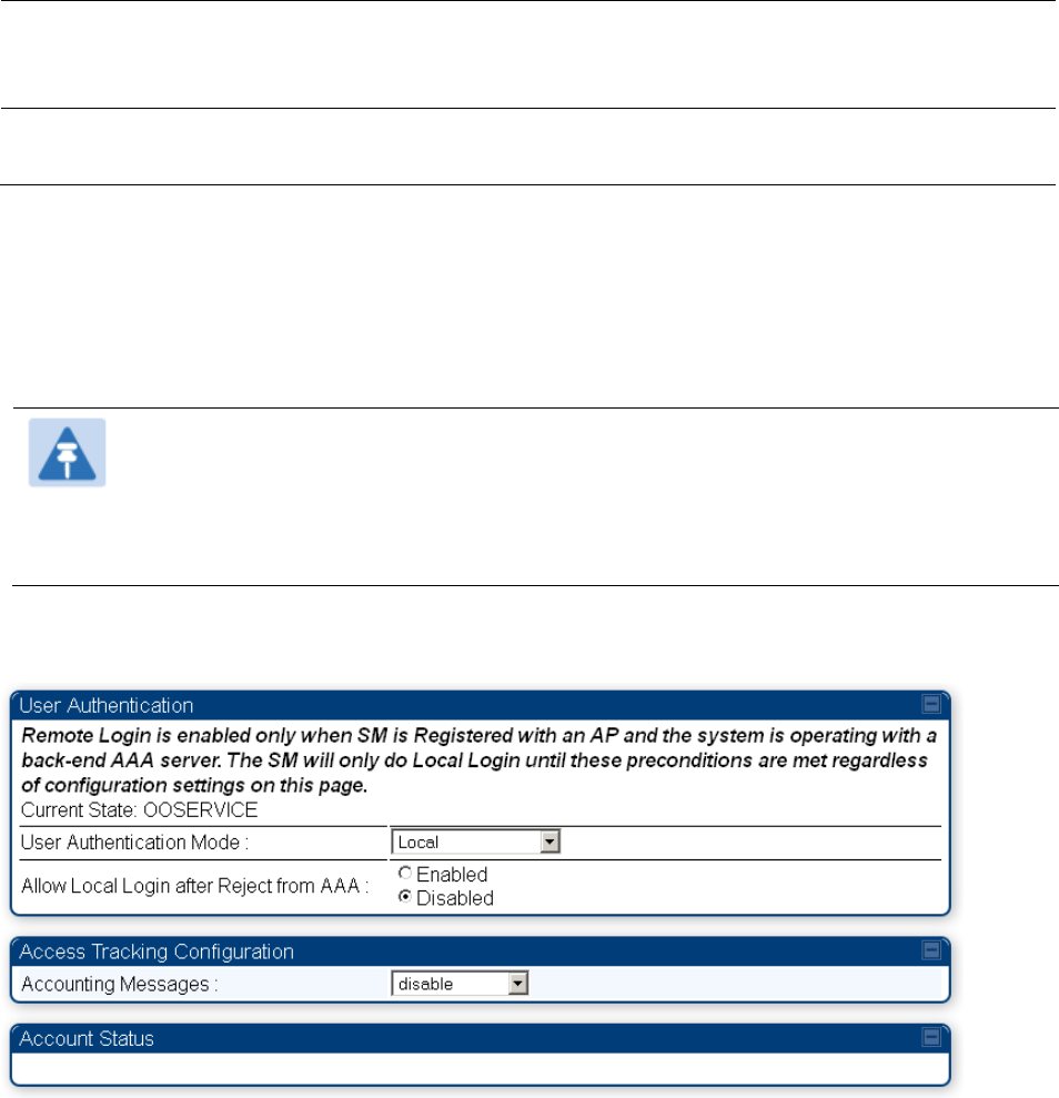
Chapter 7: Configuration
Configuring a RADIUS server
Page 7-301
Accounting Data
Usage Interval
The interval for which accounting data messages are sent from the radio
to the RADIUS server. If 0 is configured for this parameter, no data
usage messages are sent.
SM Re-authentication
Interval
The interval for which the SM will re-authenticate to the RADIUS server.
SM – Technician/Installer/Administrator
Authentication
The centralized user name and password management for SM is same as AP. Follow AP –
Technician/Installer/Administrator Authentication on page 7-299 procedure.
Note
Remote access control is enabled only after the SM registers to an AP that has
Authentication Mode set to RADIUS AAA. Local access control will always be used
before registration and is used after registration if the AP is not configured for
RADIUS.
Figure 135 User Authentication and Access Tracking tab of the SM
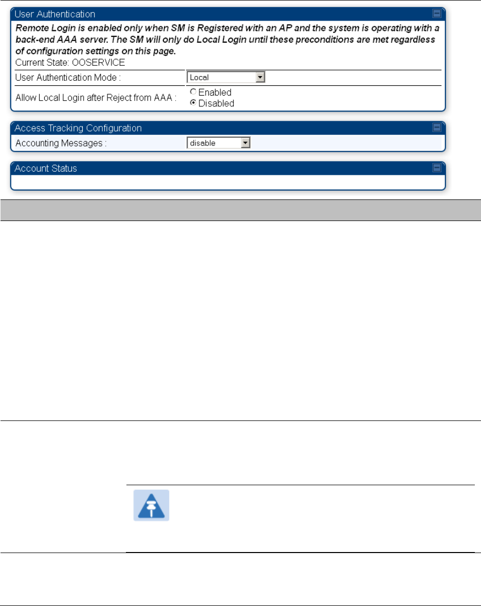
Chapter 7: Configuration
Configuring a RADIUS server
Page 7-302
Table 164 SM User Authentication and Access Tracking attributes
Attribute
Meaning
User Authentication
Mode
Local: The local SM is checked for accounts. No centralized RADIUS
accounting (access control) is performed.
Remote: Authentication by the centralized RADIUS server is required
to gain access to the SM if the SM is registered to an AP that has
RADIUS AAA Authentication Mode selected. For up to 2 minutes a
test pattern is displayed until the server responds or times out.
Remote then Local: Authentication using the centralized RADIUS
server is attempted. If the server sends a reject message, then the
setting of Allow Local Login after Reject from AAA determines if the
local user database is checked or not. If the configured servers do
not respond within 2 minutes, then the local user database is used.
The successful login method is displayed in the navigation column
of the SM.
Allow Local Login
after Reject from
AAA
If a user authentication is rejected from the AAA server, the user is
allowed to login locally to the radio’s management interface. It is
applicable ONLY when the User Authentication Mode is set to “Remote
then Local”.
Note
When the radio User Authentication Mode is set to
“Local” or “Remote”, the Allow Local Login after Reject
from AAA does not any effect.
Accounting
Messages
disable – no accounting messages are sent to the RADIUS server
deviceAccess – accounting messages are sent to the RADIUS server
regarding device access (see Table 165).

Chapter 7: Configuration
Configuring a RADIUS server
Page 7-303
Access
Tracking
To track logon and logoff times on individual radios by technicians, installers, and
administrators, on the AP or SM’s Account > User Authentication and Access Tracking tab
under
Accounting (Access Tracking) set Accounting Messages to “deviceAccess”.
Device Access Tracking is enabled separately from User Authentication Mode. A given AP
or
SM
can be configured for both, either, or
neither.
RADIUS Device Data Accounting
PMP 450 systems include support for RADIUS accounting messages for usage-based billing. This
accounting includes indications for subscriber session establishment, subscriber session
disconnection, and bandwidth usage per session for each SM that connects to the AP. The
attributes included in the RADIUS accounting messages are shown in the table below.
Table 165 Device data accounting RADIUS attributes
Sender
Message
Attribute
Value
Description
AP
Accounting-
Request
Acct-Status-Type
1 - Start
This message is
sent every time a
SM registers with
an AP, and after
the SM stats are
cleared.
Acct-Session-Id
Unique per AP session.
Initial value is SM MAC, and
increments after every start
message sent of an in
session SM.
Event-Timestamp
UTC time the event
occurred on the AP
AP
Accounting-
Request
Acct-Status-Type
2 - Stop
This message is
sent every time a
SM becomes
unregistered with
an AP, and when
the SM stats are
cleared.
Acct-Session-Id
Unique per AP session.
Initial value is SM MAC, and
increments after every start
message sent of an in
session SM.
Acct-Input-Octets
Sum of the input octets
received at the SM over
regular data VC and the
high priority data VC (if
enabled). Will not include
broadcast.
Acct-Output-Octets
Sum of the output octets
sent from the SM over
regular data VC and the
high priority data VC (if
enabled).

Chapter 7: Configuration
Configuring a RADIUS server
Page 7-304
Sender
Message
Attribute
Value
Description
Acct-Input-
Gigawords
Number of times the Acct-
Input-Octets counter has
wrapped around 2^32 over
the course of the session
Acct-Output-
Gigawords
Number of times the Acct-
Output-Octets counter has
wrapped around 2^32 over
the course of the session
Acct-Input-Packets
Sum of unicast and
multicast packets that are
sent to a particular SM over
the regular data VC and the
high priority data VC (if
enabled). It will not include
broadcast.
Acct-Output-
Packets
Sum of unicast and
multicast packets that are
sent from a particular SM
over the regular data VC
and the high priority data
VC (if enabled).
Acct-Session-Time
Uptime of the SM session.
Acct-Terminate-
Cause
Reason code for session
termination
AP
Accounting-
Request
Acct-Status-Type
3 - Interim-Update
This message is
sent periodically
per the operator
configuration on
the AP in seconds.
Interim update
counts are
cumulative over
the course of the
session
Acct-Session-Id
Unique per AP session.
Initial value is SM MAC, and
increments after every start
message sent of an in
session SM.
Acct-Input-Octets
Sum of the input octets sent
to the SM over regular data
VC and the high priority
data VC (if enabled). Will
not include broadcast.
Acct-Output-Octets
Sum of the output octets
set from the SM over
regular data VC and the
high priority data VC (if
enabled).
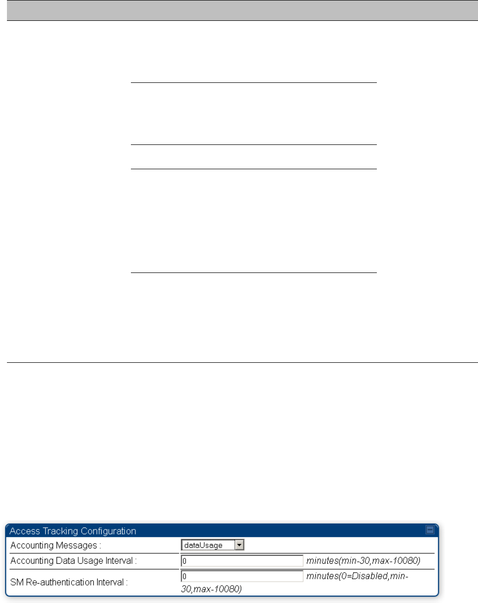
Chapter 7: Configuration
Configuring a RADIUS server
Page 7-305
Sender
Message
Attribute
Value
Description
Acct-Input-
Gigawords
Number of times the Acct-
Input-Octets counter has
wrapped around 2^32 over
the course of the session
Acct-Output-
Gigawords
Number of times the Acct-
Output-Octets counter has
wrapped around 2^32 over
the course of the session
Acct-Session-Time
Uptime of the SM session.
Acct-Input-Packets
Sum of unicast and
multicast packets that are
sent to a particular SM over
the regular data VC and the
high priority data VC (if
enabled). It will not include
broadcast.
Acct-Output-
Packets
Sum of unicast and
multicast packets that are
sent from a particular SM
over the regular data VC
and the high priority data
VC (if enabled).
The data accounting configuration is located on the AP’s Accounts > User Authentication and
Access Tracking GUI menu, and the AP’s Authentication Mode must be set to Radius AAA for the
menu to appear. The accounting may be configured via the AP GUI as shown in the figures below.
By default accounting messages are not sent and the operator has the choice of configuring to
send only Device Access accounting messages (when a user logs in or out of the radio), only Data
Usage messages, or both. When Data Accounting is enabled, the operator must specify the
interval of when the data accounting messages are sent (0 – disabled, or in the range of 30-10080
minutes). The default interval is 30 minutes.
Figure 136 RADIUS accounting messages configuration
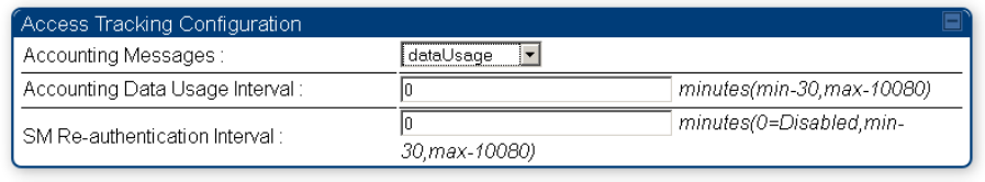
Chapter 7: Configuration
Configuring a RADIUS server
Page 7-306
The data accounting message data is based on the SM statistics that the AP maintains, and these
statistics may be cleared on the AP by an operator. If an operator clears these messages and data
accounting is enabled, an accounting stop message is sent followed by an accounting start
message to notify the AAA of the change.
If an operator clears the VC statistics on the device through the management GUI, a RADIUS stop
message and data start message is issued for each device affected. The start and stop messages
will only be sent once every 5 minutes, so if an operator clears these statistics multiple times
within 5 minutes, only one set of data stop/start messages is sent. This may result in inaccurate
data accumulation results.
RADIUS Device Re-authentication
PMP 450 platform systems include support for periodic SM re-authentication in a network without
requiring the SM to re-register (and drop the session). The re-authentication may be configured to
occur in the range of every 30 minutes to weekly.
Figure 137 Device re-authentication configuration
The re-authentication interval is only configurable on the AP. When this feature is enabled, each
SM that enters the network will re-authenticate each the interval time has expired without
dropping the session. The response that the SM receives from the AAA server upon re-
authentication is one of the following:
Success: The SM continues normal operation
Reject: The SM de-registers and will attempt network entry again after 1 minute and then if
rejected will attempt re-entry every 15 minutes
Timeout or other error: The SM remains in session and attempt 5 times to re-authenticate with
the RADIUS-REQUEST message. If these attempts fail, then the SM will go out of session and
proceed to re-authenticate after 5 minutes, then every 15 minutes.
Although re-authentication is an independent feature, it was designed to work alongside with the
RADIUS data usage accounting messages. If a user is over their data usage limit the network
operator can reject the user from staying in the network. Operators may configure the RADIUS
‘Reply-Message’ attribute with an applicable message (i.e. “Data Usage Limit Reached”) that is
sent to the subscriber module and displayed on the general page.
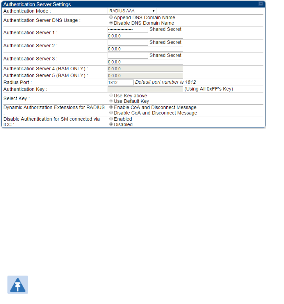
Chapter 7: Configuration
Configuring a RADIUS server
Page 7-307
RADIUS Change of Authorization and Disconnect Message
Prior to this feature, SM will get configuration parameters from a RADIUS server during
authentication process. This feature allows an administrator to control configuration parameters in
the SM while SM is in session. The configuration changes in SM are done using RADIUS Change
of Authorization method (RFC 3576) on the existing RADIUS authentication framework for AP and
SM. A typical use case could be changing the QOS parameters after a certain amount of
bandwidth usage by a SM.
Figure 138 RADIUS CoA configuration for AP
The RADIUS CoA feature enables initiating a bi-directional communication from the RADIUS
server(s) to the AP and SM.
The AP listens on UDP port 3799 and accepts CoA requests from the configured RADIUS servers.
This CoA request should contain SM MAC address in ‘User-Name’ attribute as identifier and all
other attributes which control the SM config parameters. For security reasons, a timestamp also
needs to be added as ‘Event-Timestamp’ attribute. Hence the time should also be synchronized
between the RADIUS server(s) and the AP to fit within a window of 300 seconds.
Once the configuration changes are applied on the SM, CoA-ACK message is sent back to RADIUS
server. If the validation fails, the AP sends a CoA-NACK response to the RADIUS server with proper
error code.
A Disconnect-Message is sent by the RADIUS server to NAS in order to terminate a user session
on a NAS and discard all associated session context. It is used when the authentication AAA server
wants to disconnect the user after the session has been accepted by the RADIUS.
In response of Disconnect-Request from RADIUS server, the NAS sends a Disconnect-ACK if all
associated session context is discarded, or a Disconnect-NACK, if the NAS is unable to disconnect
the session.
Note
The RADIUS CoA feature will only enabled if Authentication mode is set to RADIUS
AAA.