Cambium Networks 50450M 5GHz Point to MultiPoint Multi User MIMO Access Point User Manual USERS MANUAL PART4
Cambium Networks Limited 5GHz Point to MultiPoint Multi User MIMO Access Point USERS MANUAL PART4
Contents
- 1. USER GUIDE P1
- 2. USER GUIDE P2
- 3. USER GUIDE P3
- 4. USER GUIDE P4
- 5. User manual
- 6. User Manual
- 7. USERS MANUAL PART1
- 8. USERS MANUAL PART2
- 9. USERS MANUAL PART3
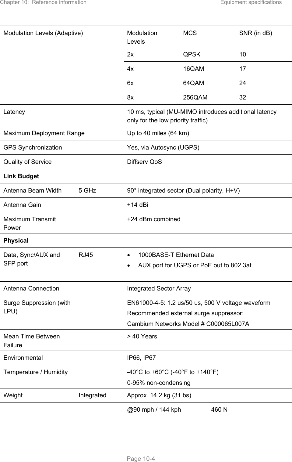
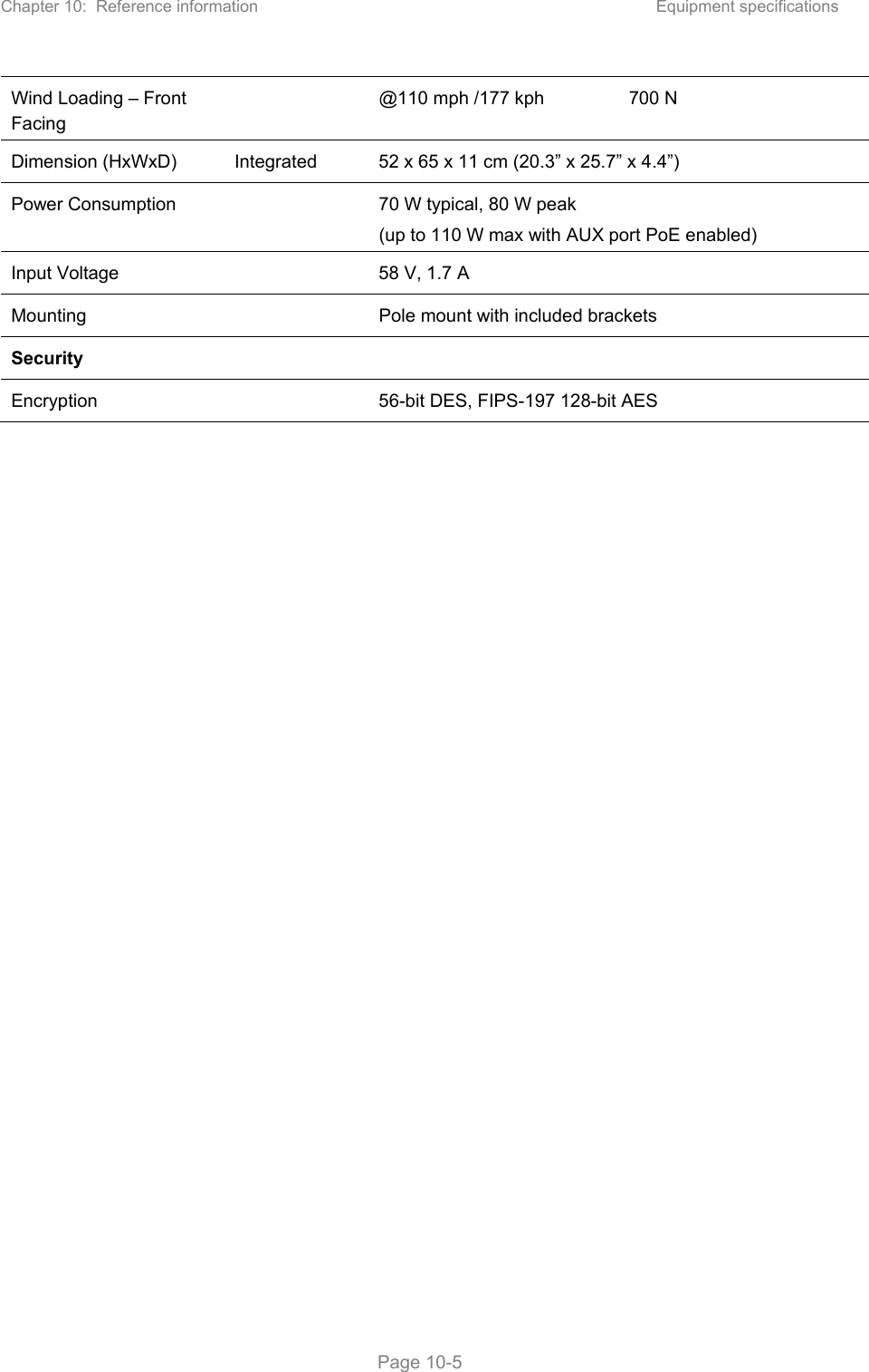
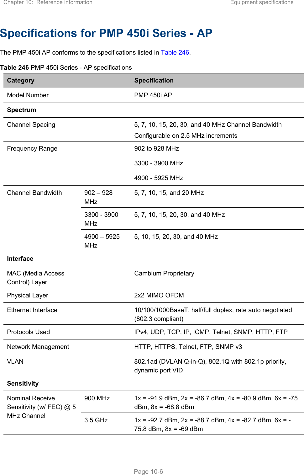
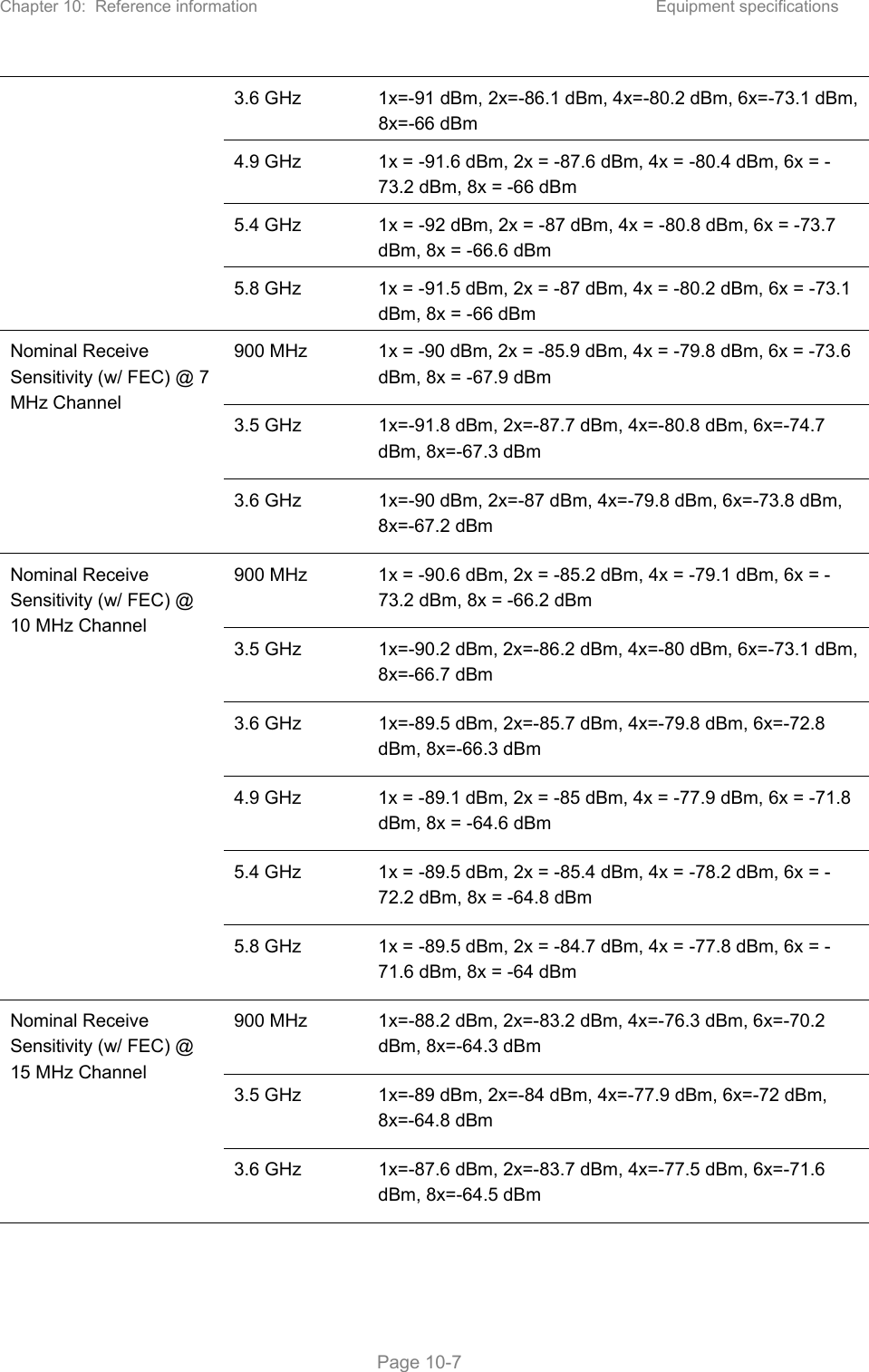
- 10. USERS MANUAL PART4
- 11. USER MANUAL PART1
- 12. USER MANUAL PART2
- 13. USER MANUAL PART 3
- 14. USER MANUAL PART 4
- 15. USER MANUAL PT1
- 16. USER MANUAL PT2
- 17. USER MANUAL PT3
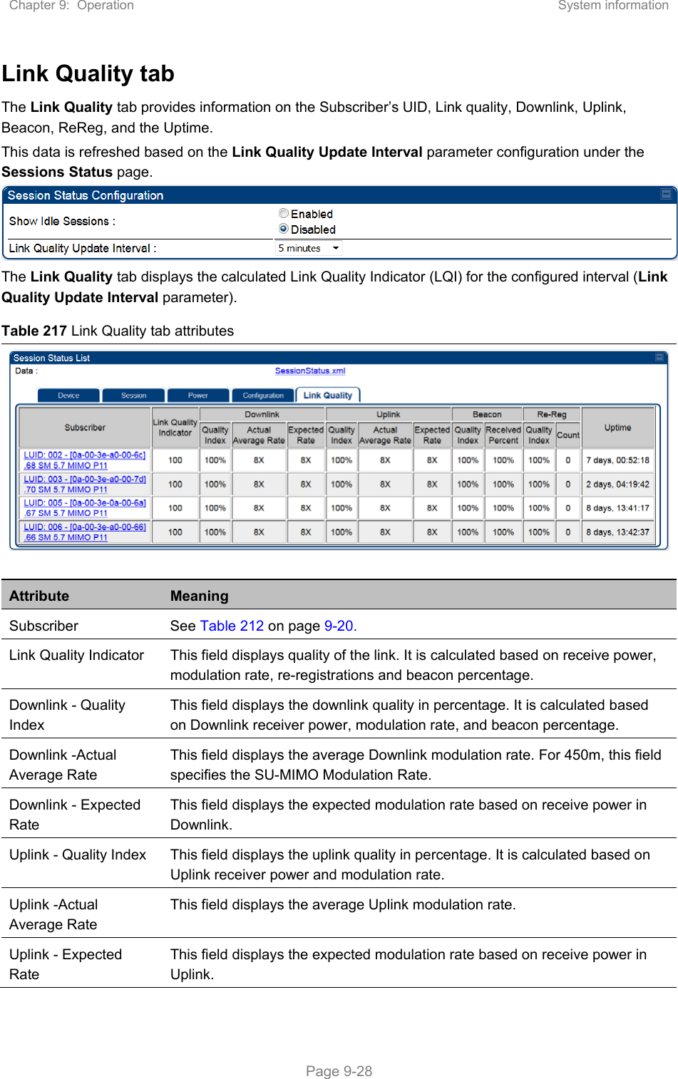
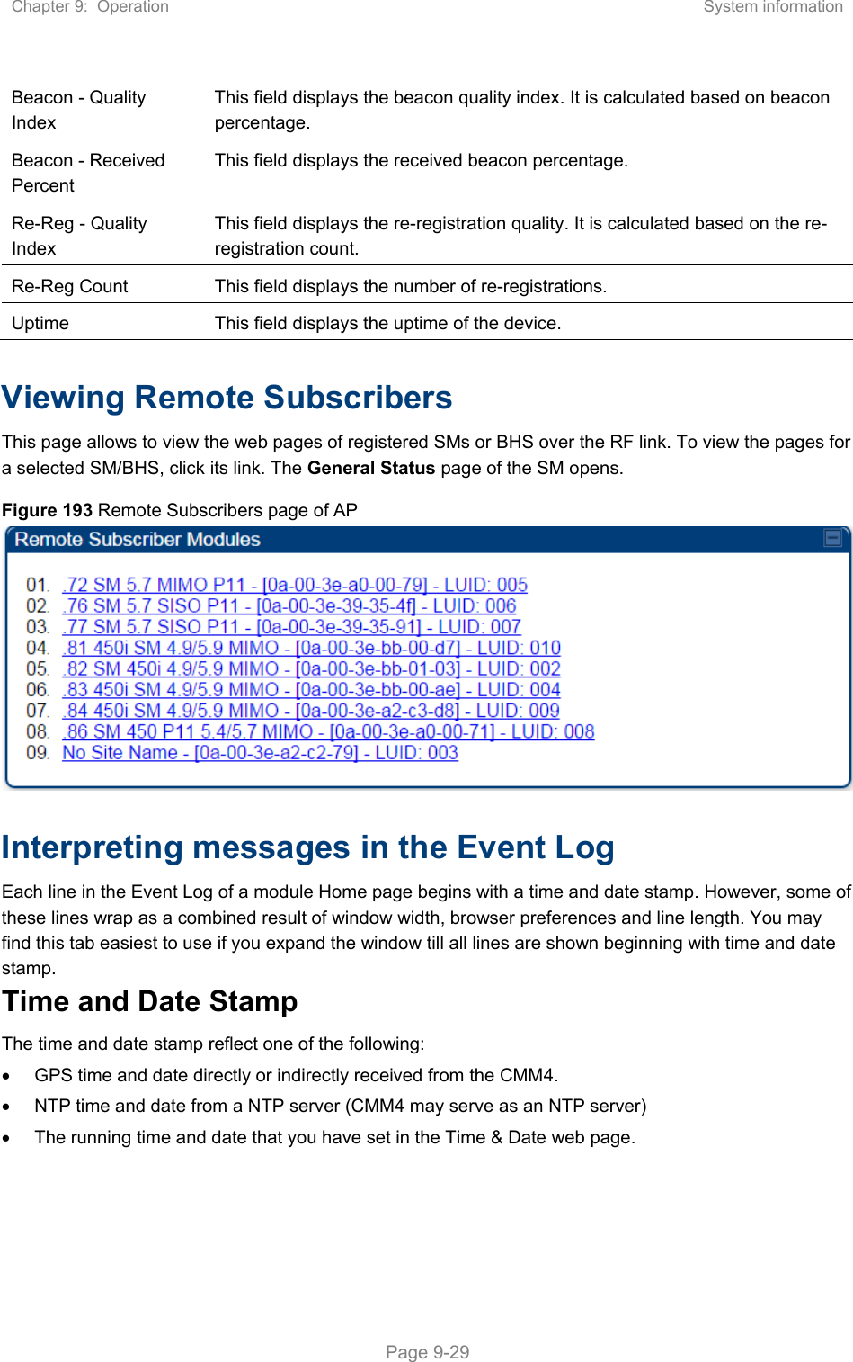
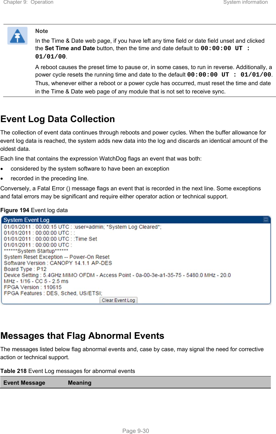
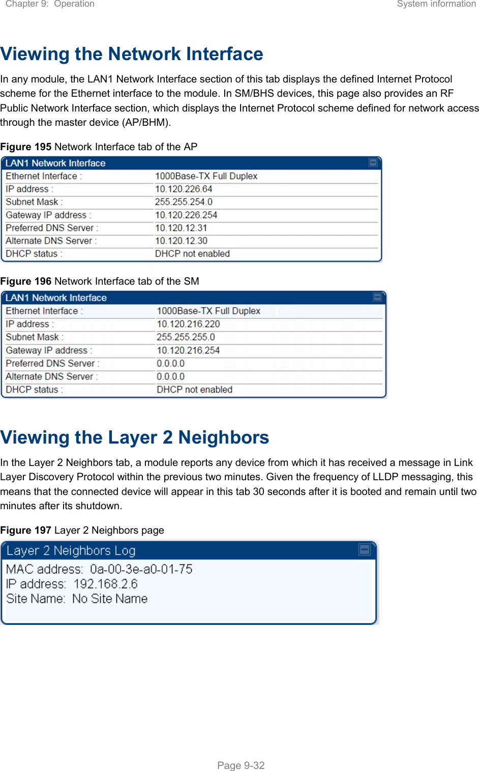
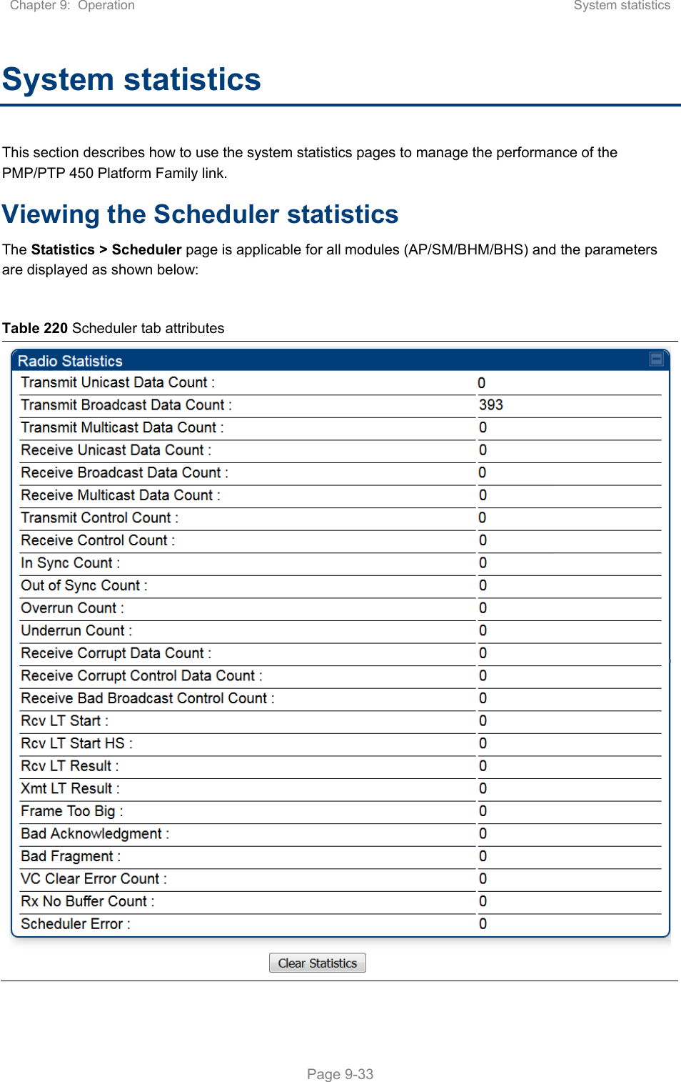
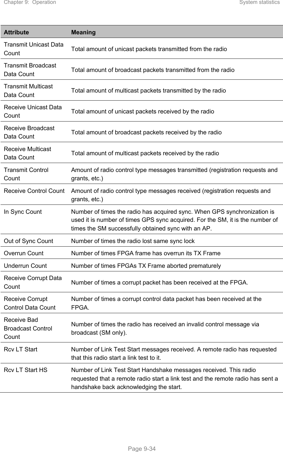
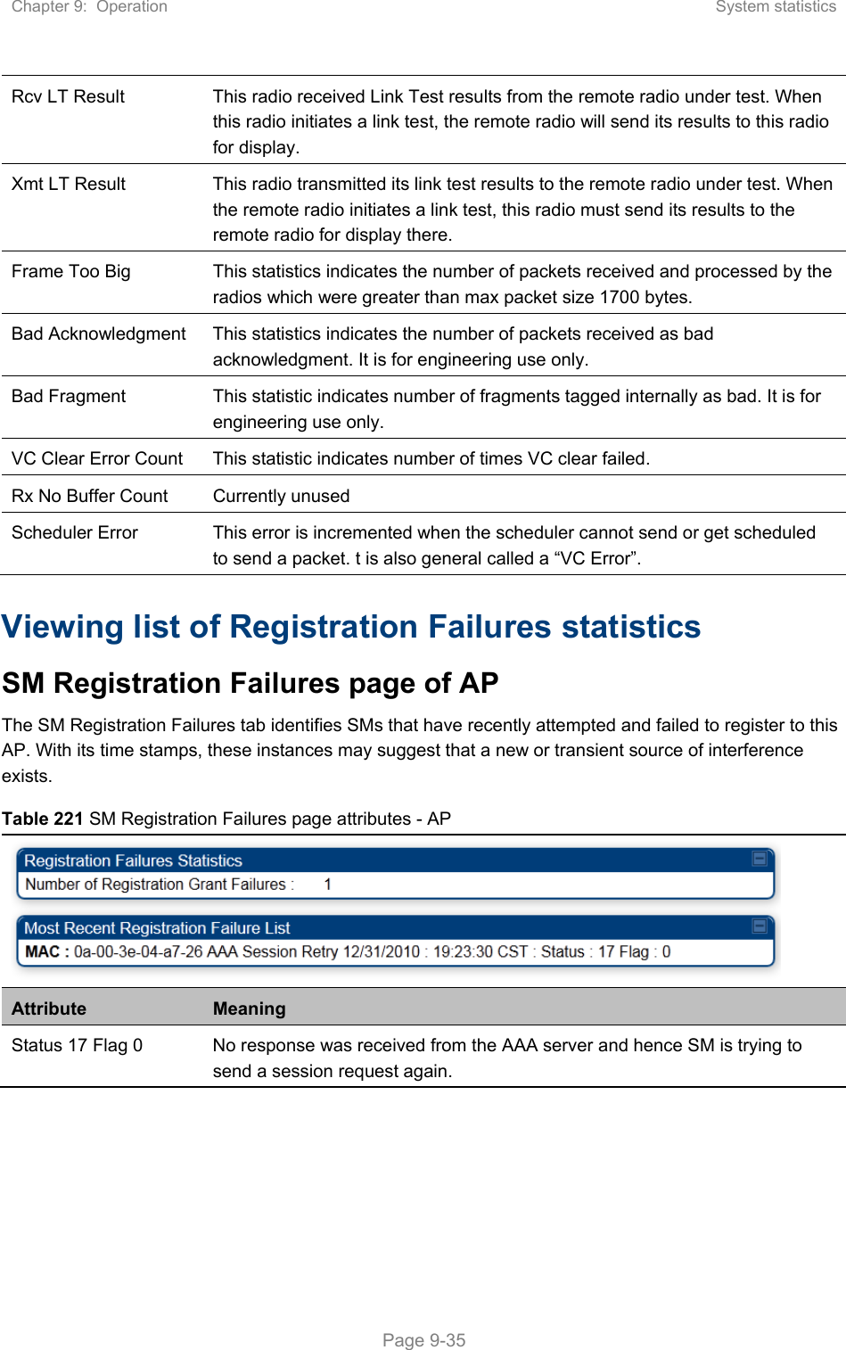
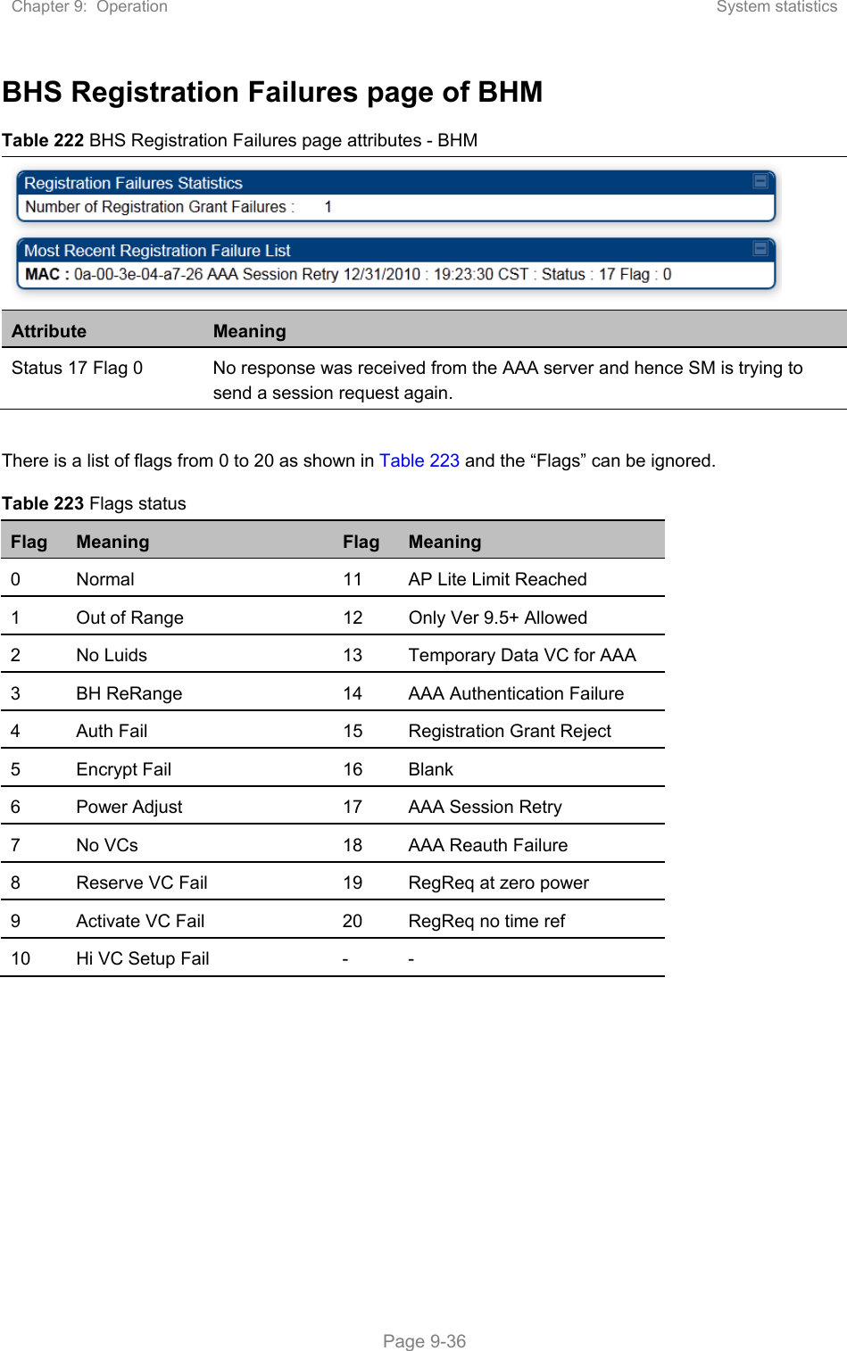
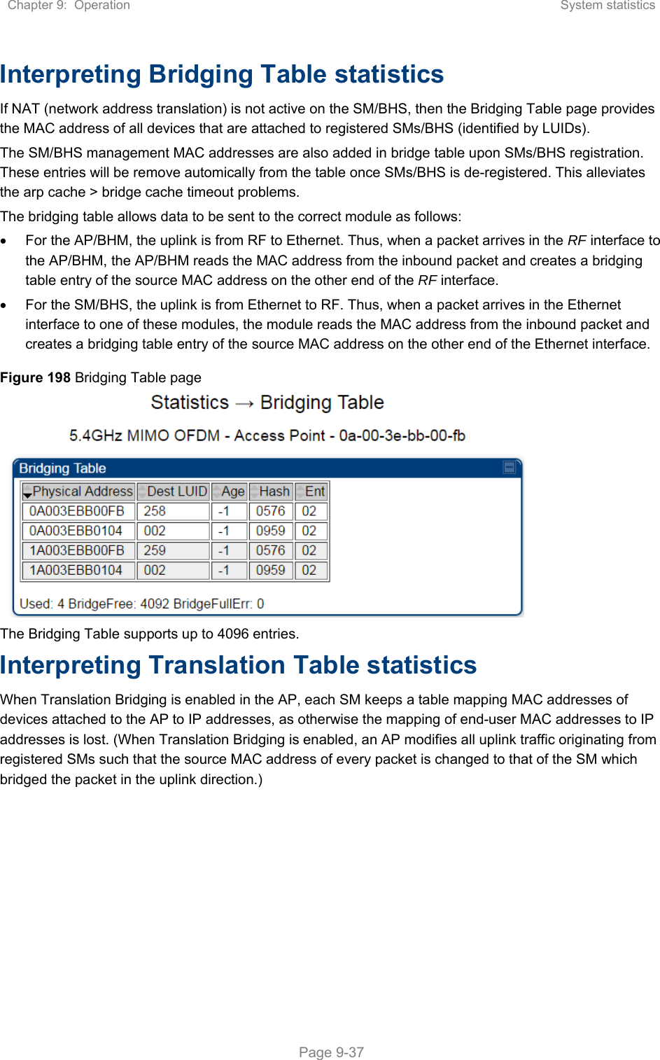
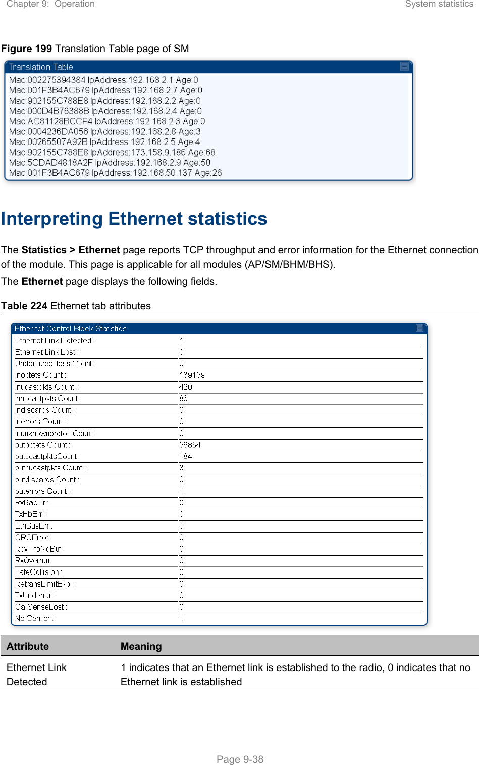
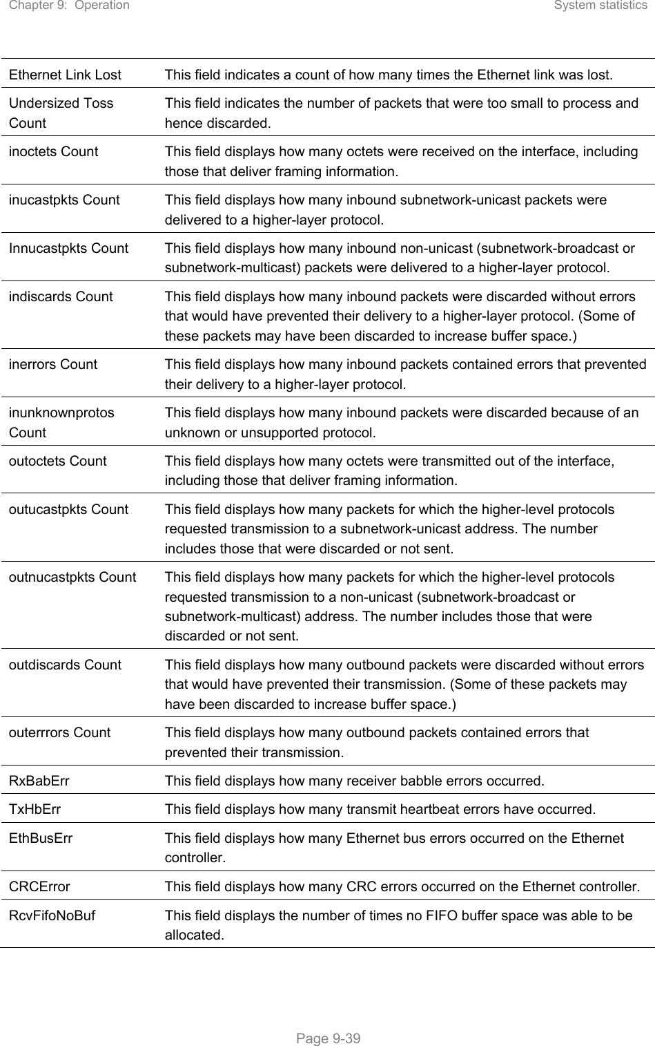
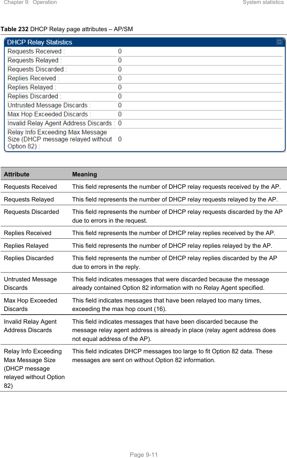
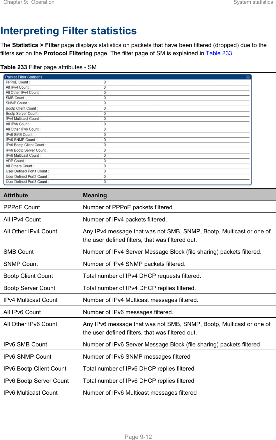
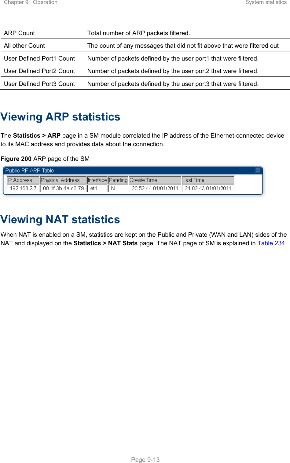
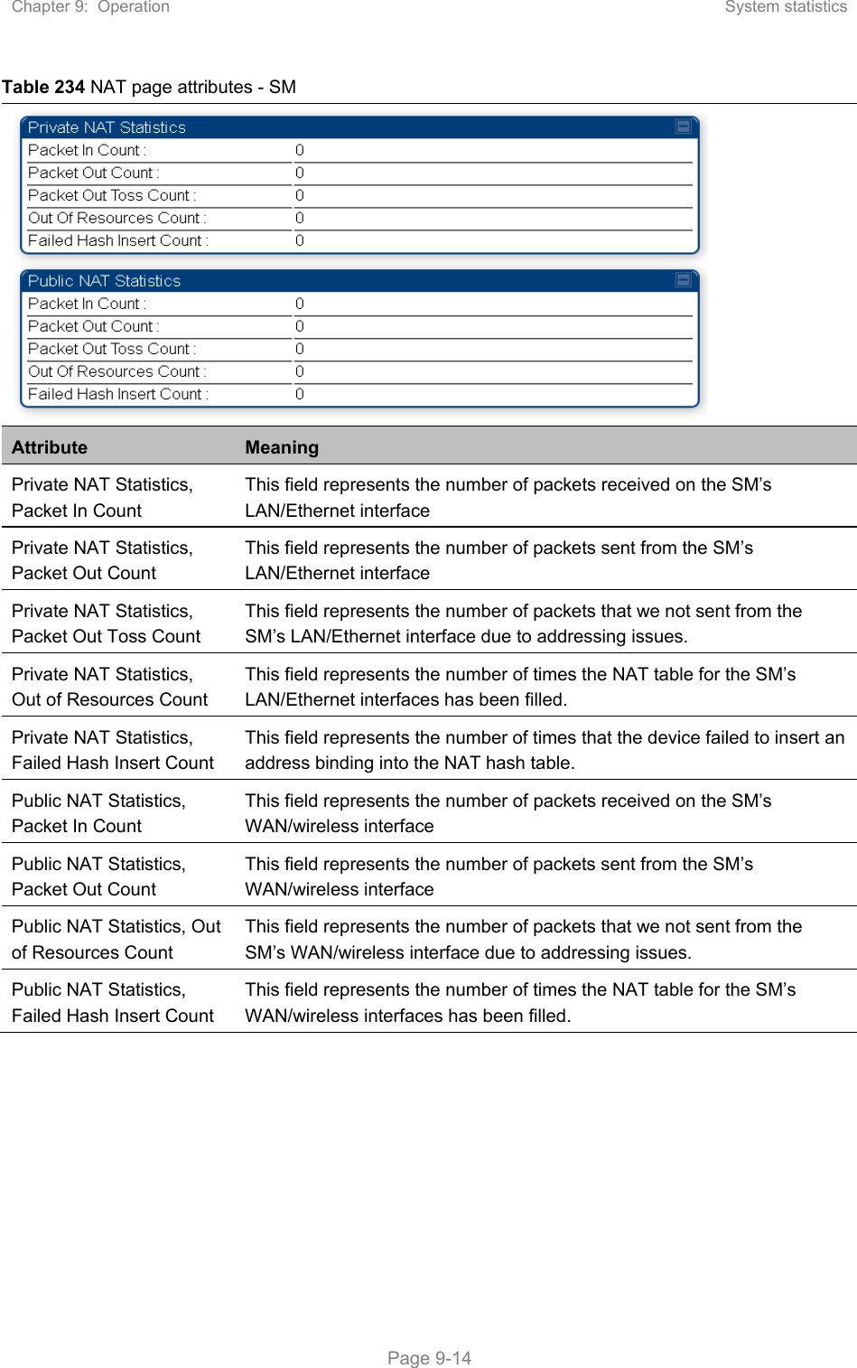
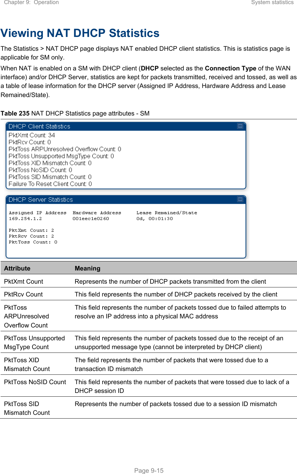
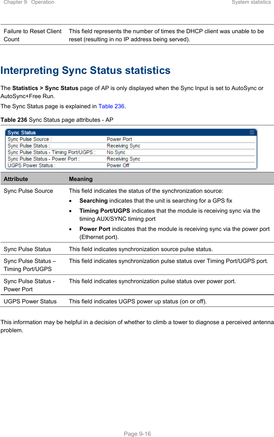
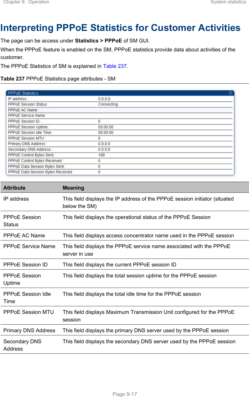
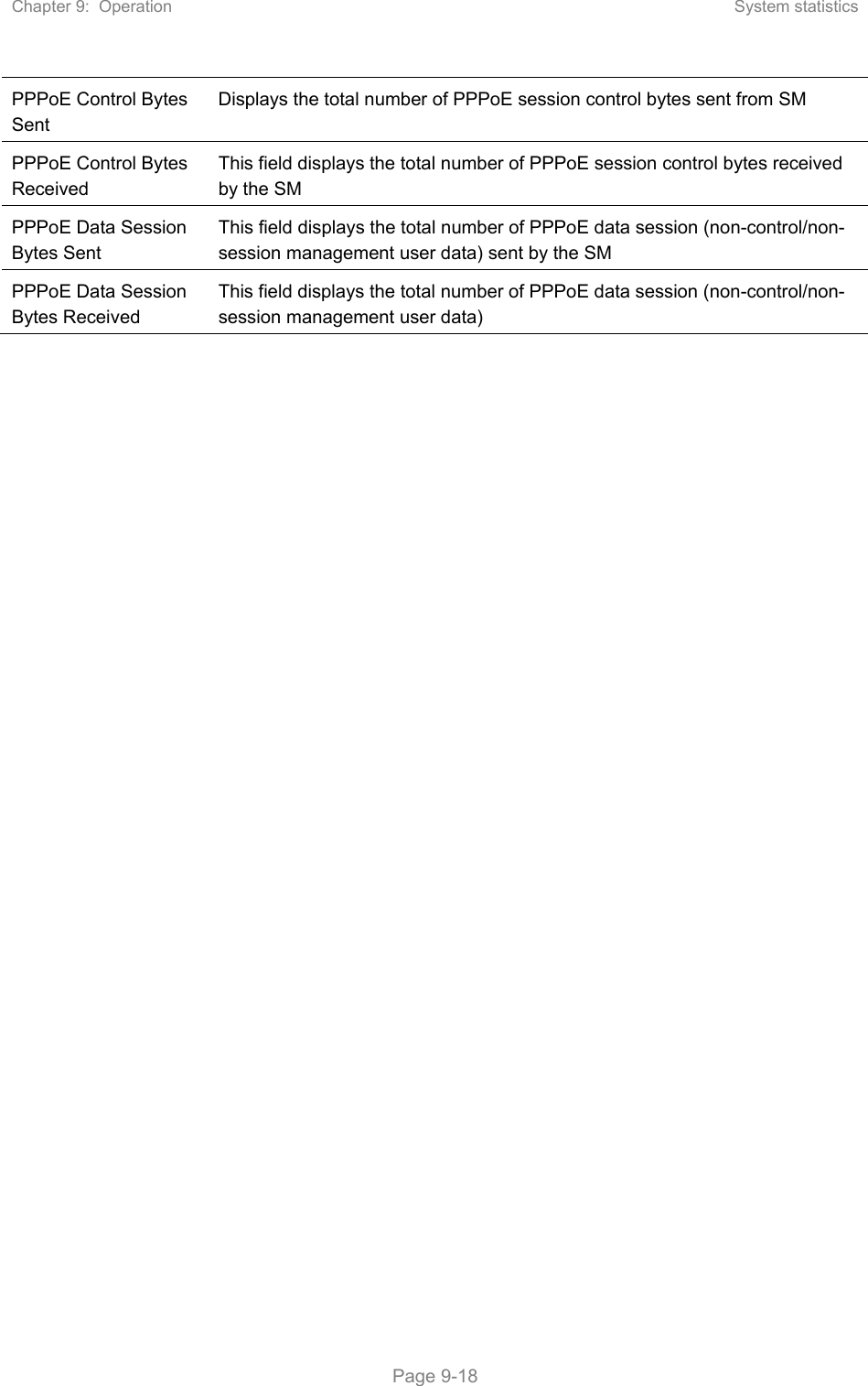
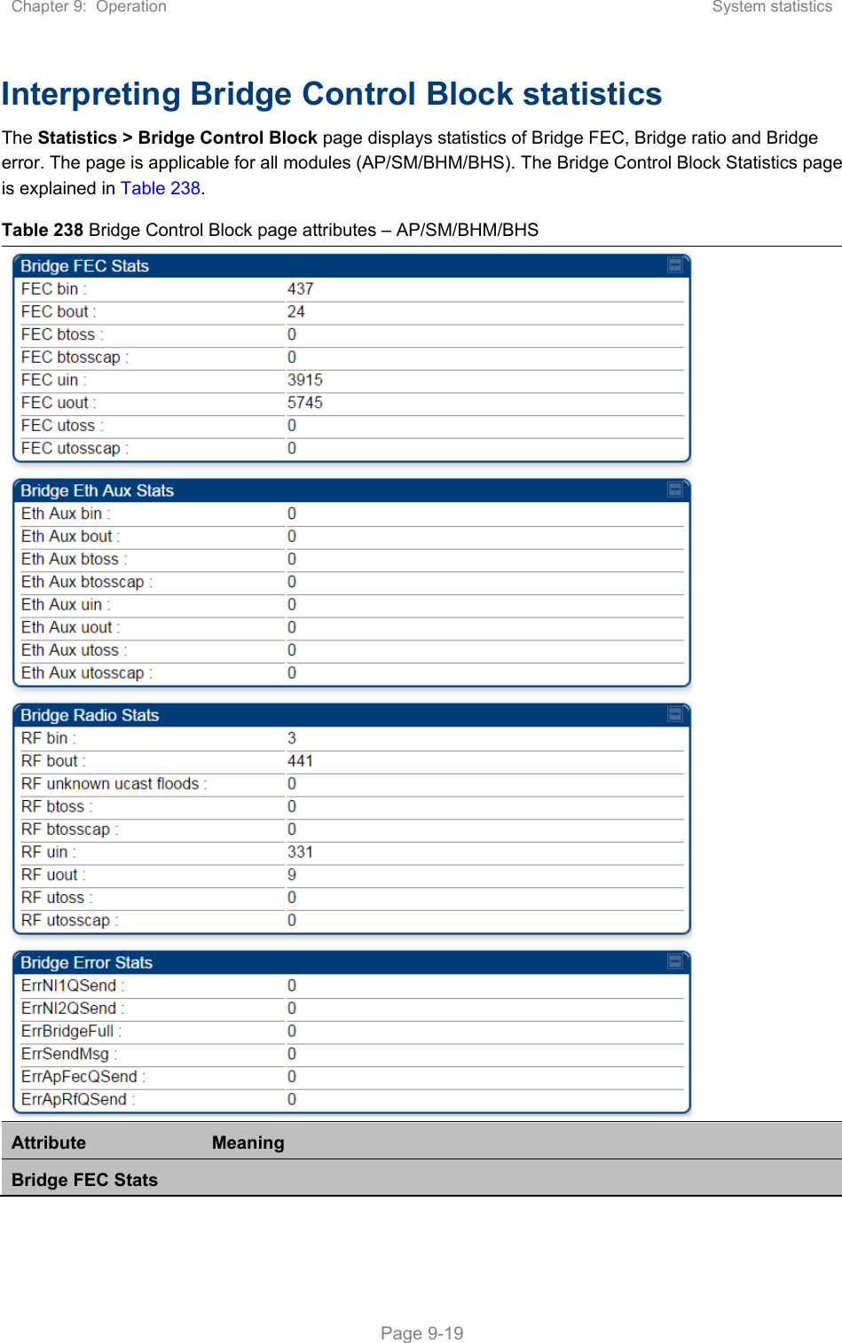
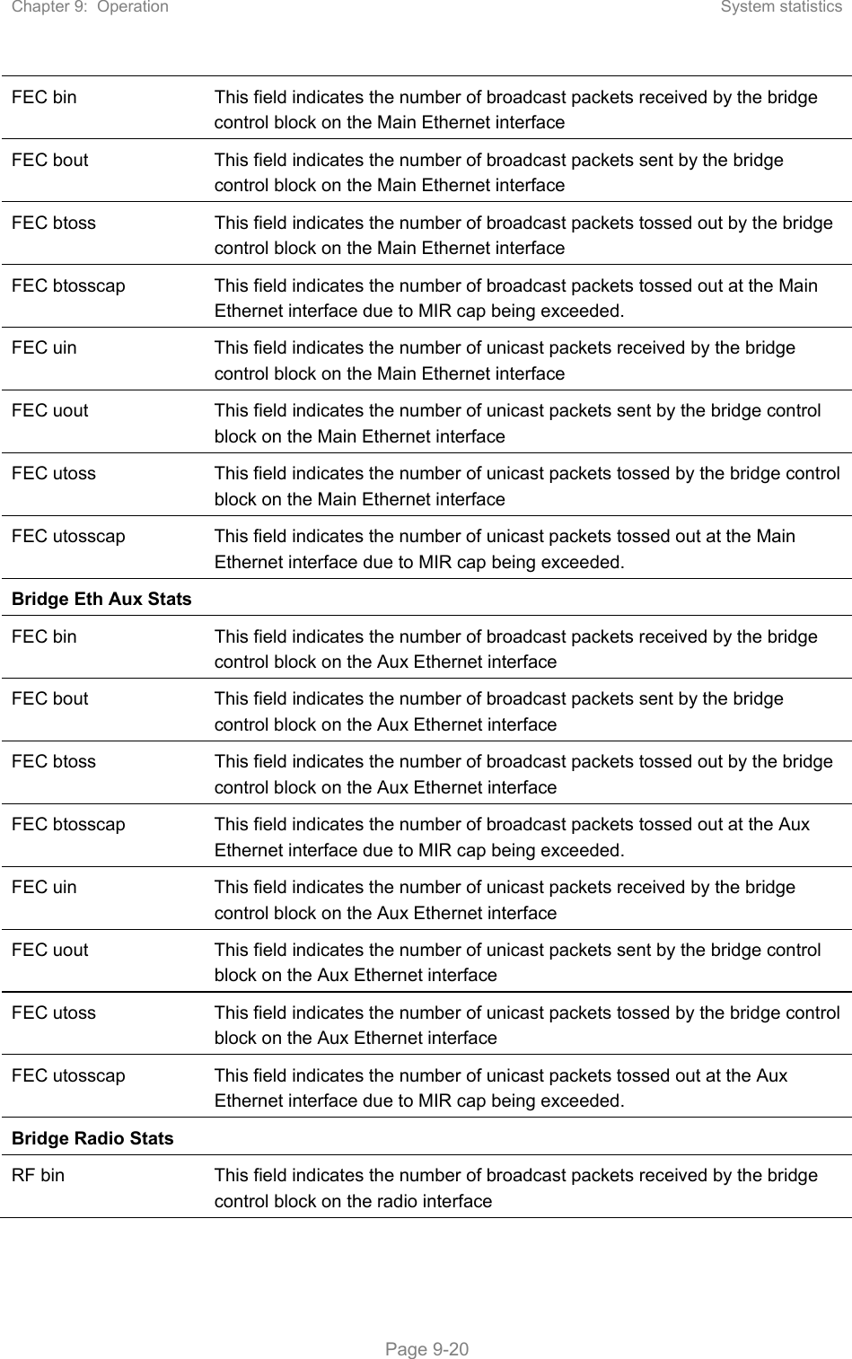
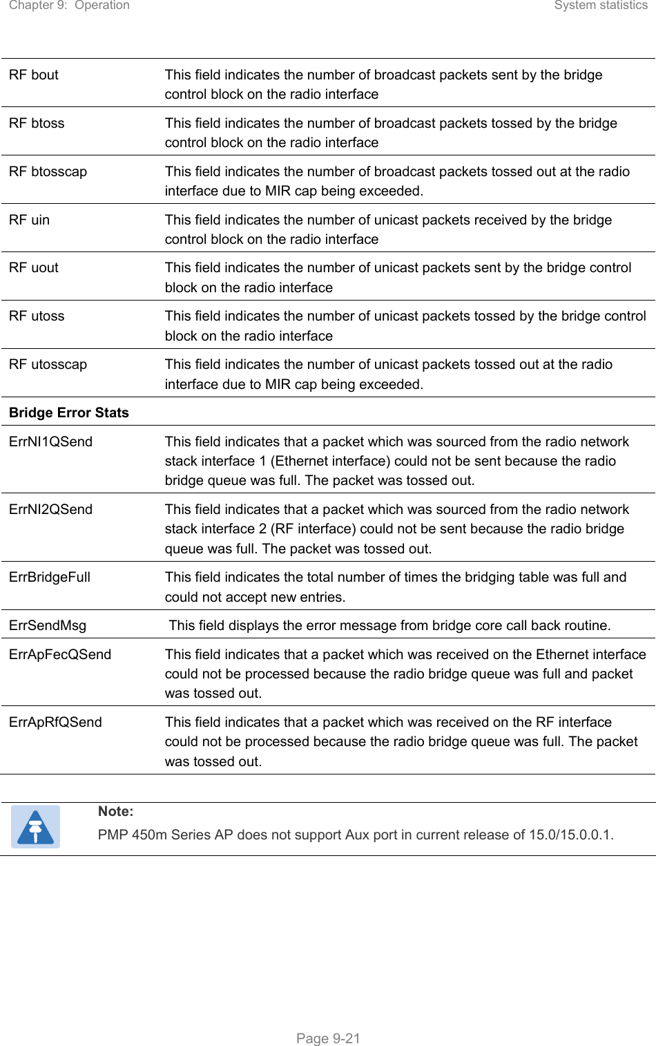
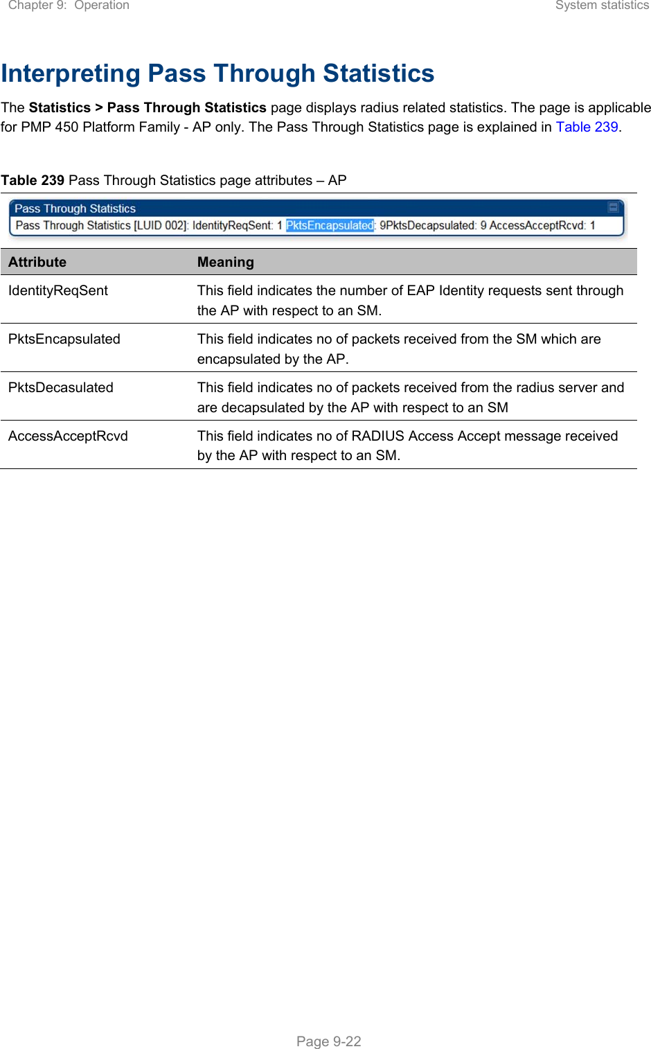
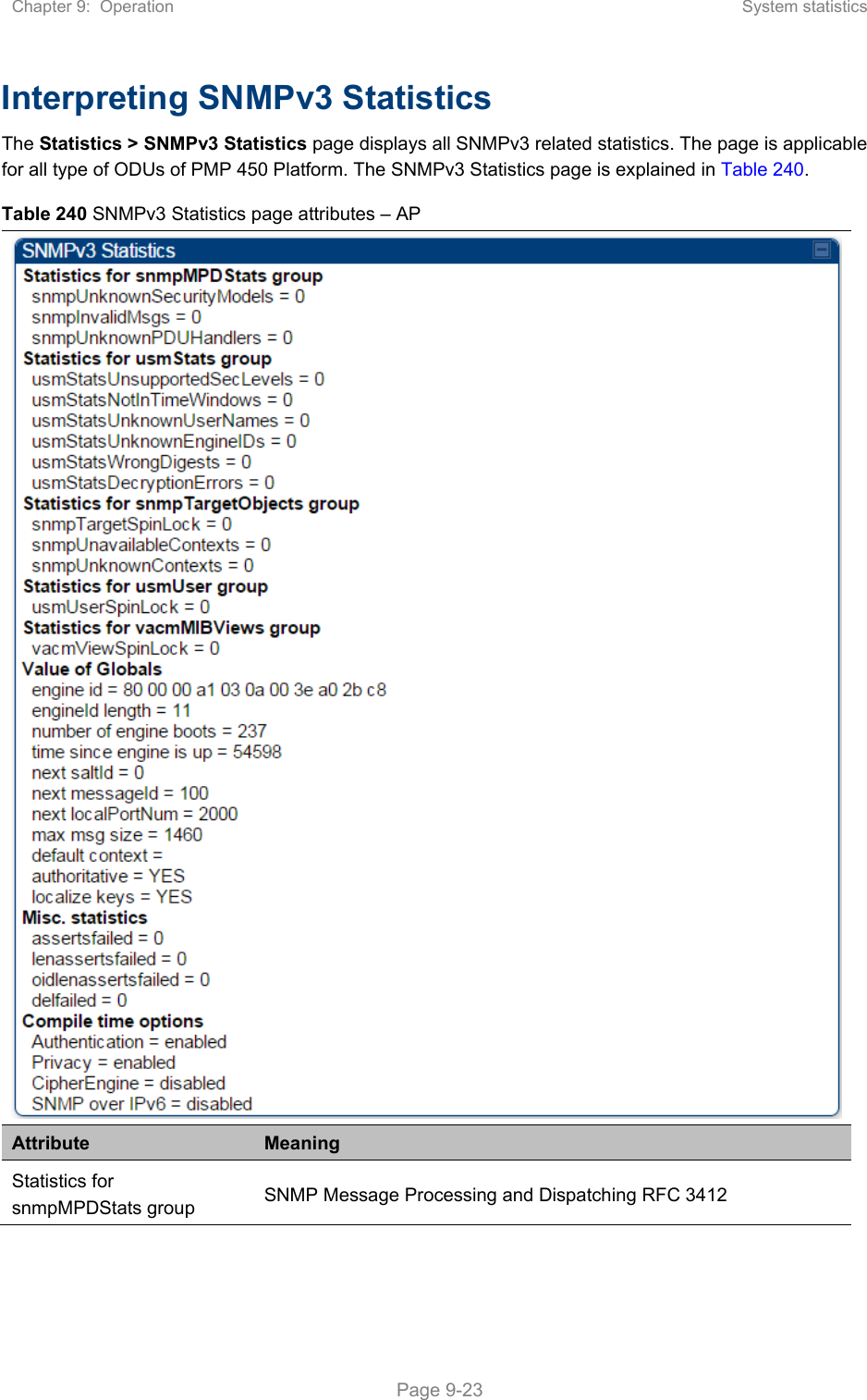
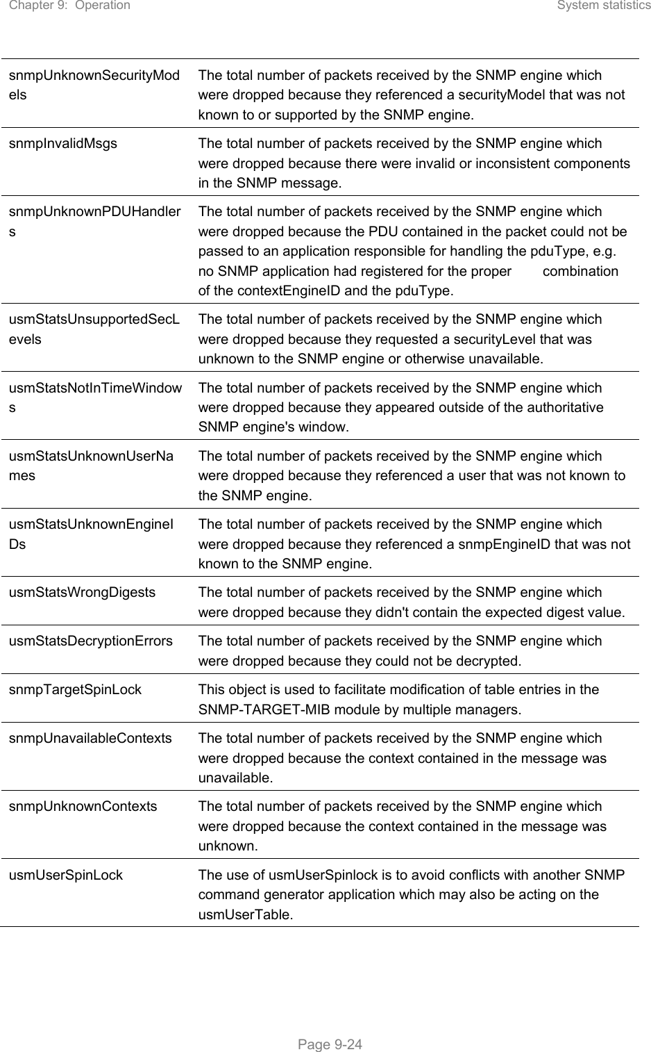
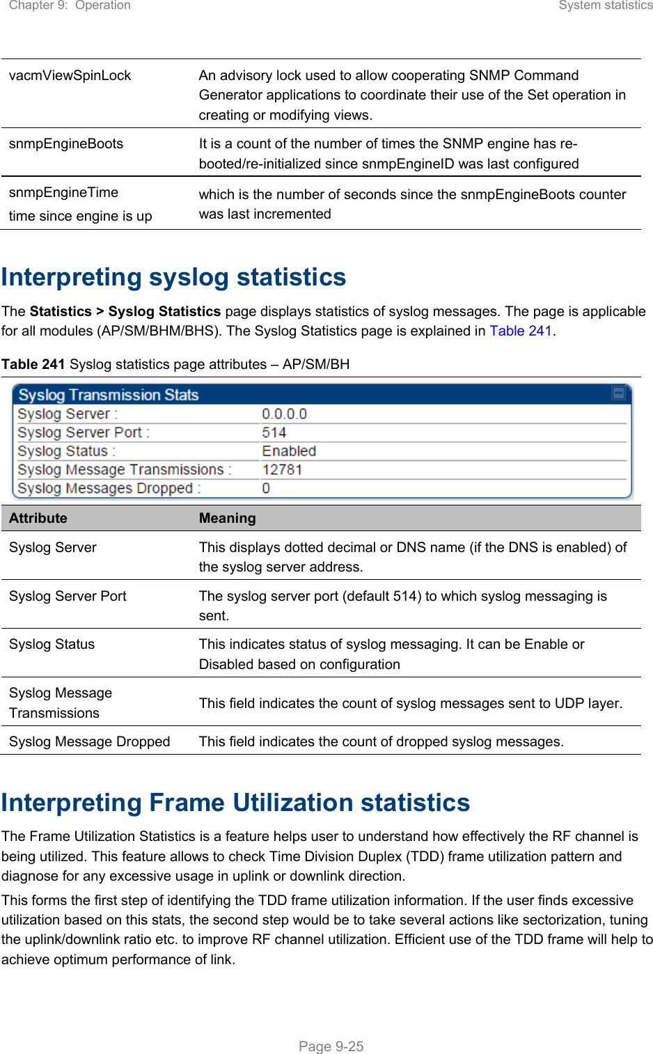
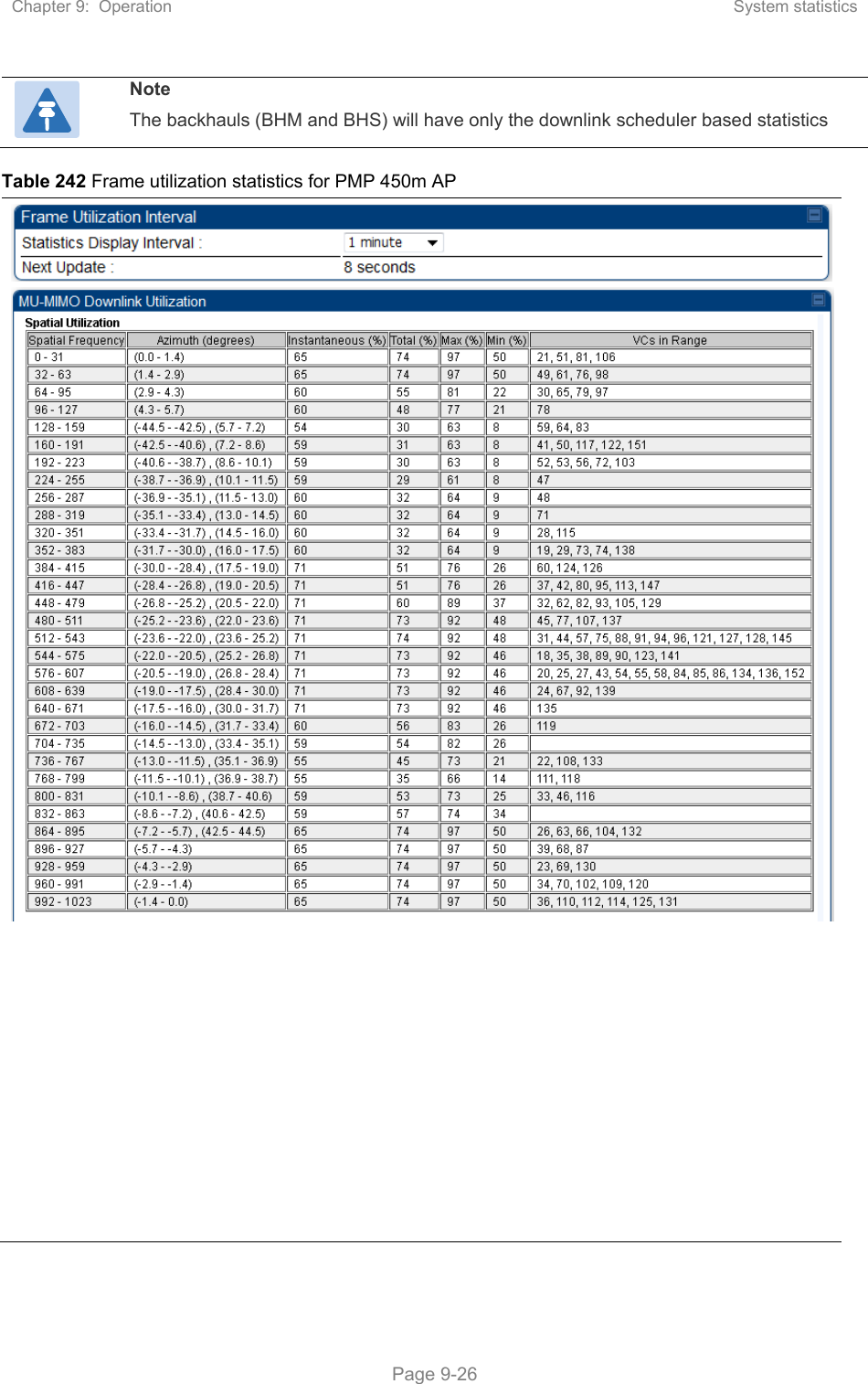
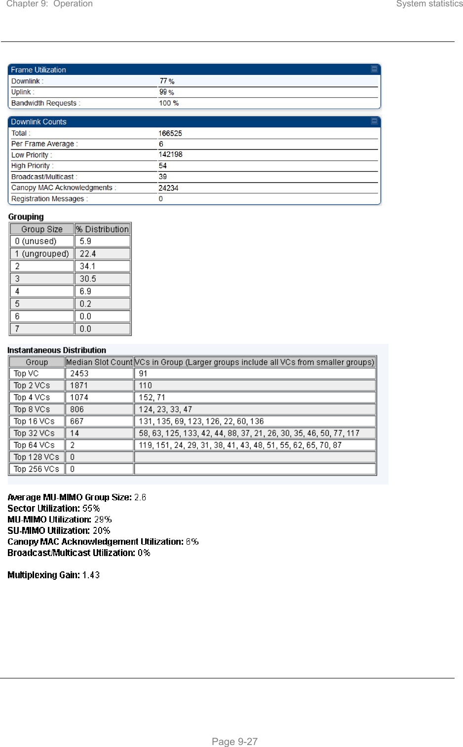
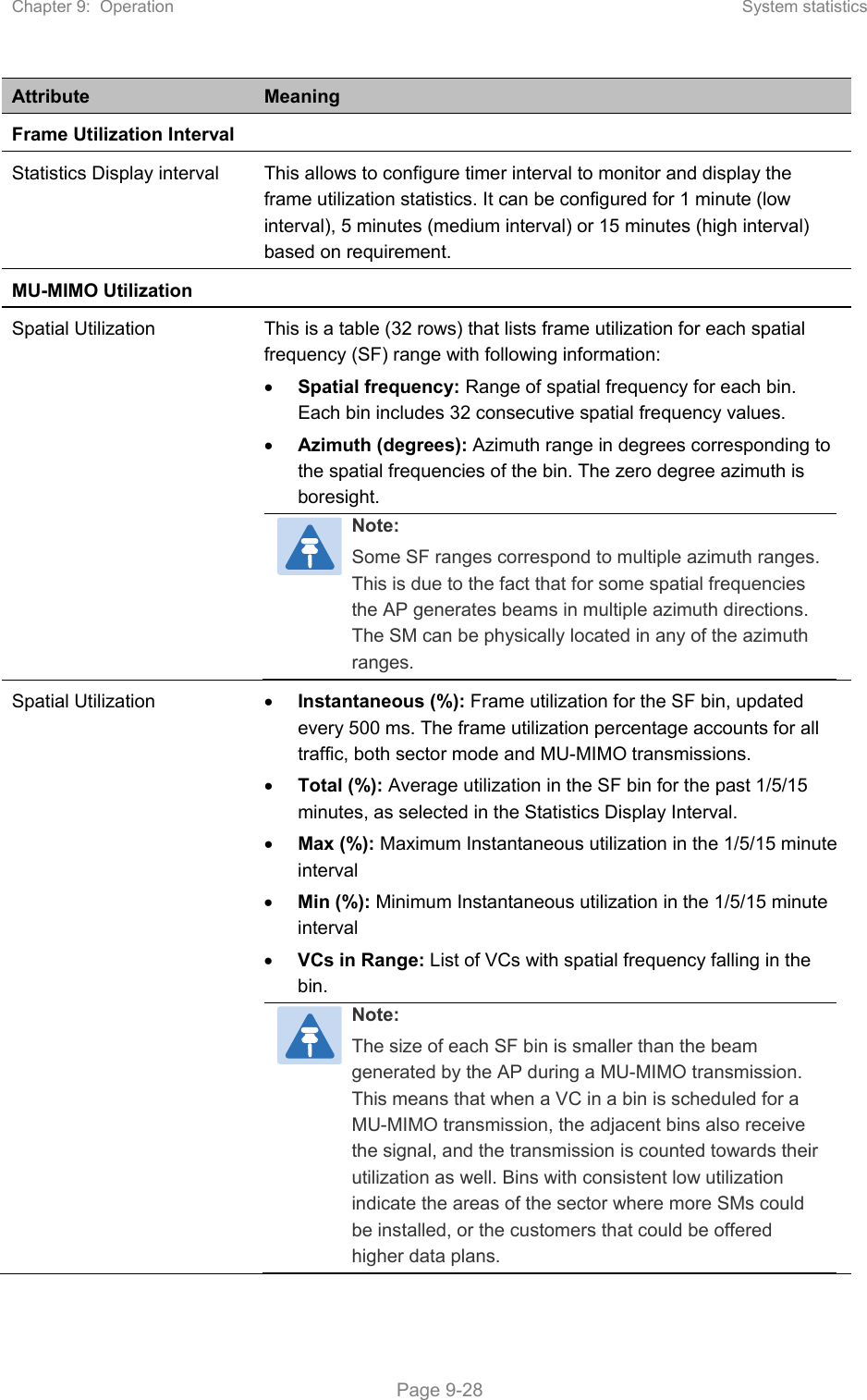
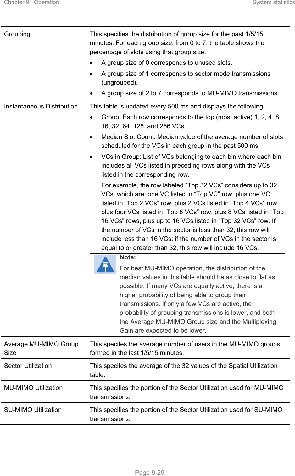
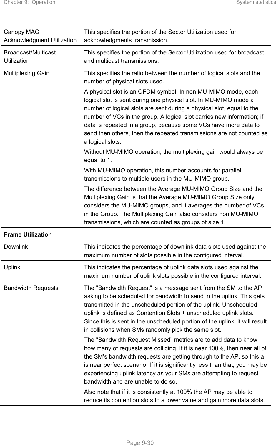
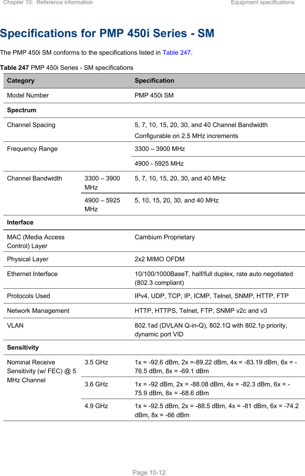
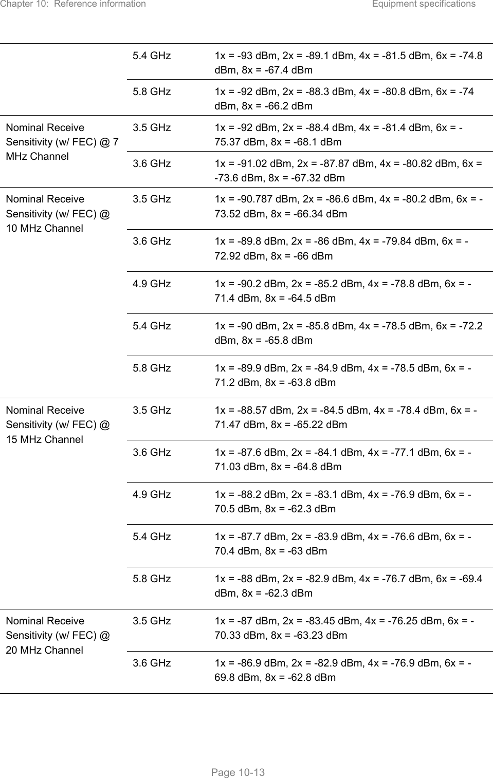
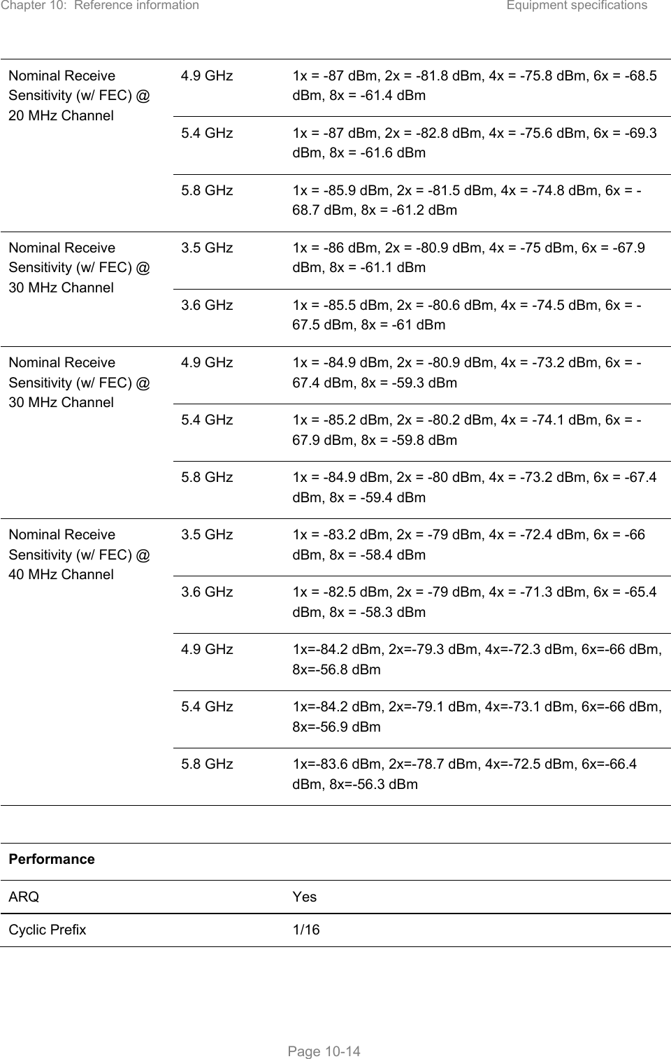
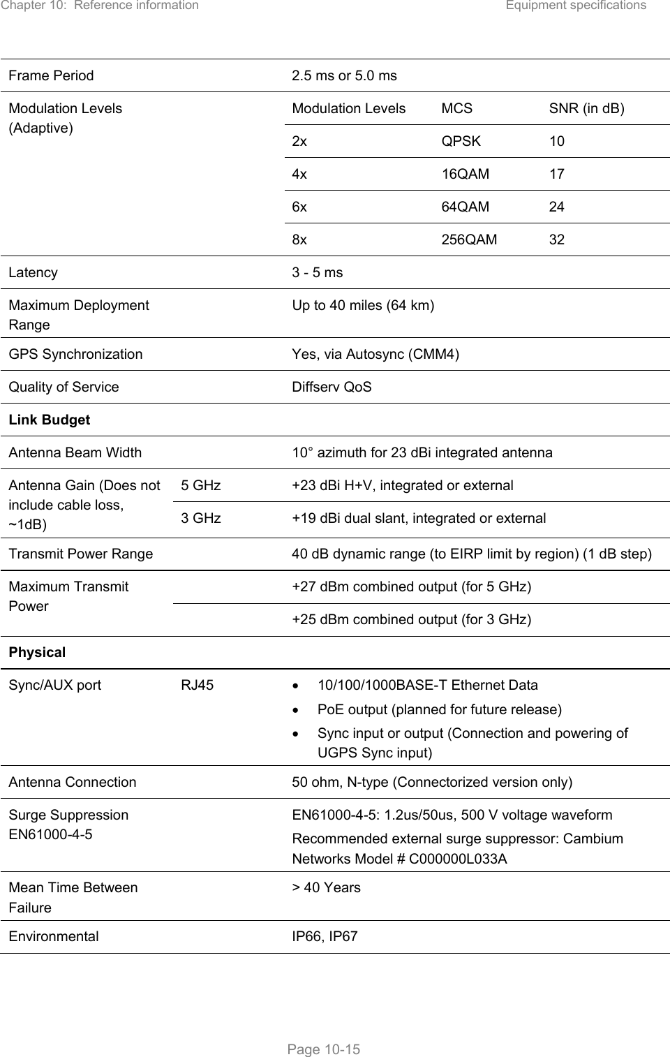
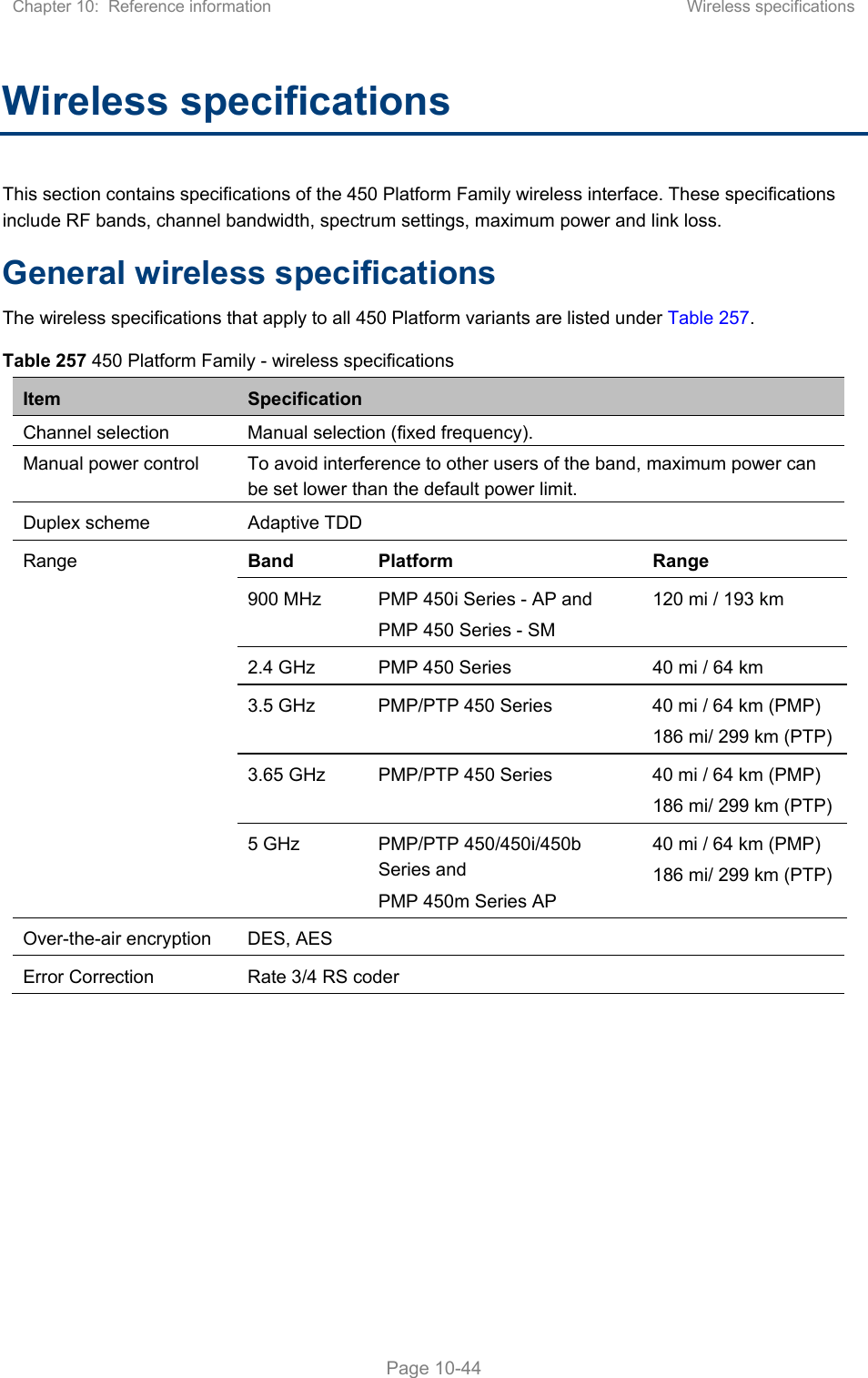
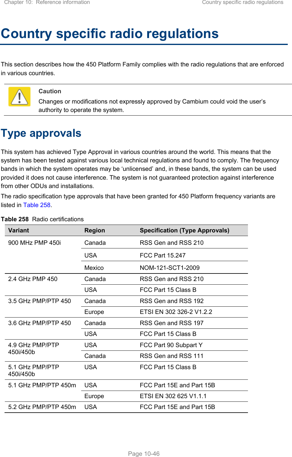
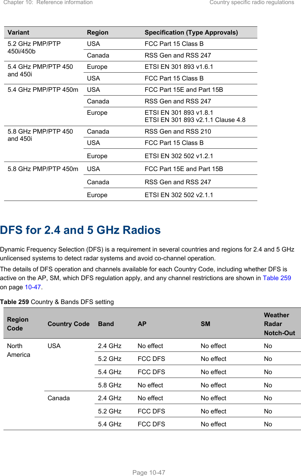
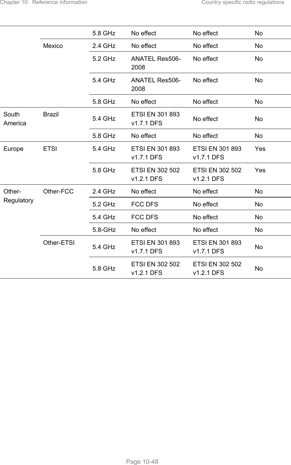
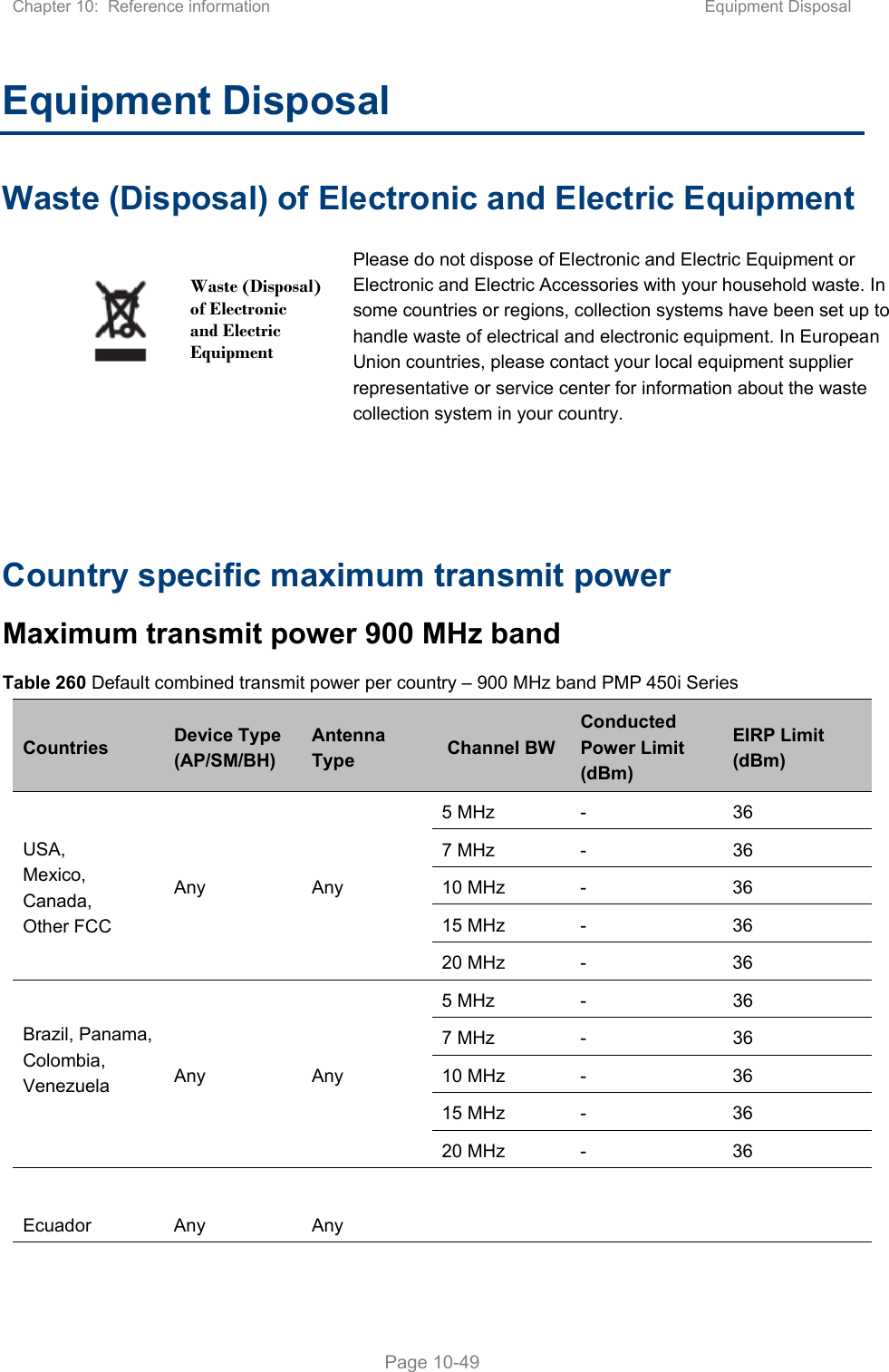
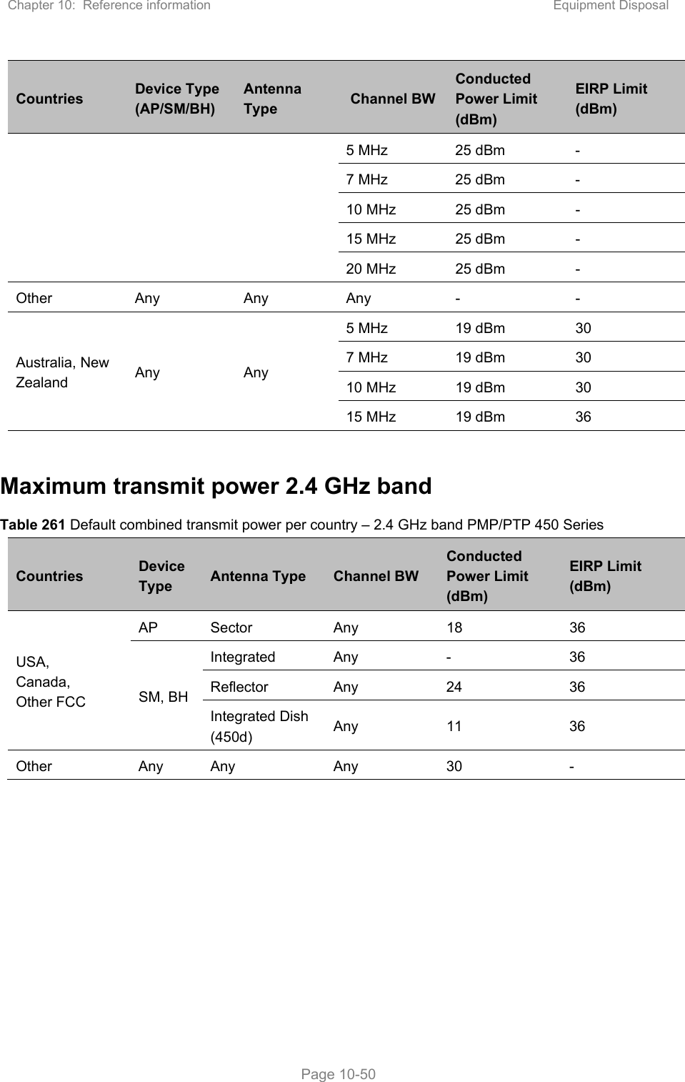
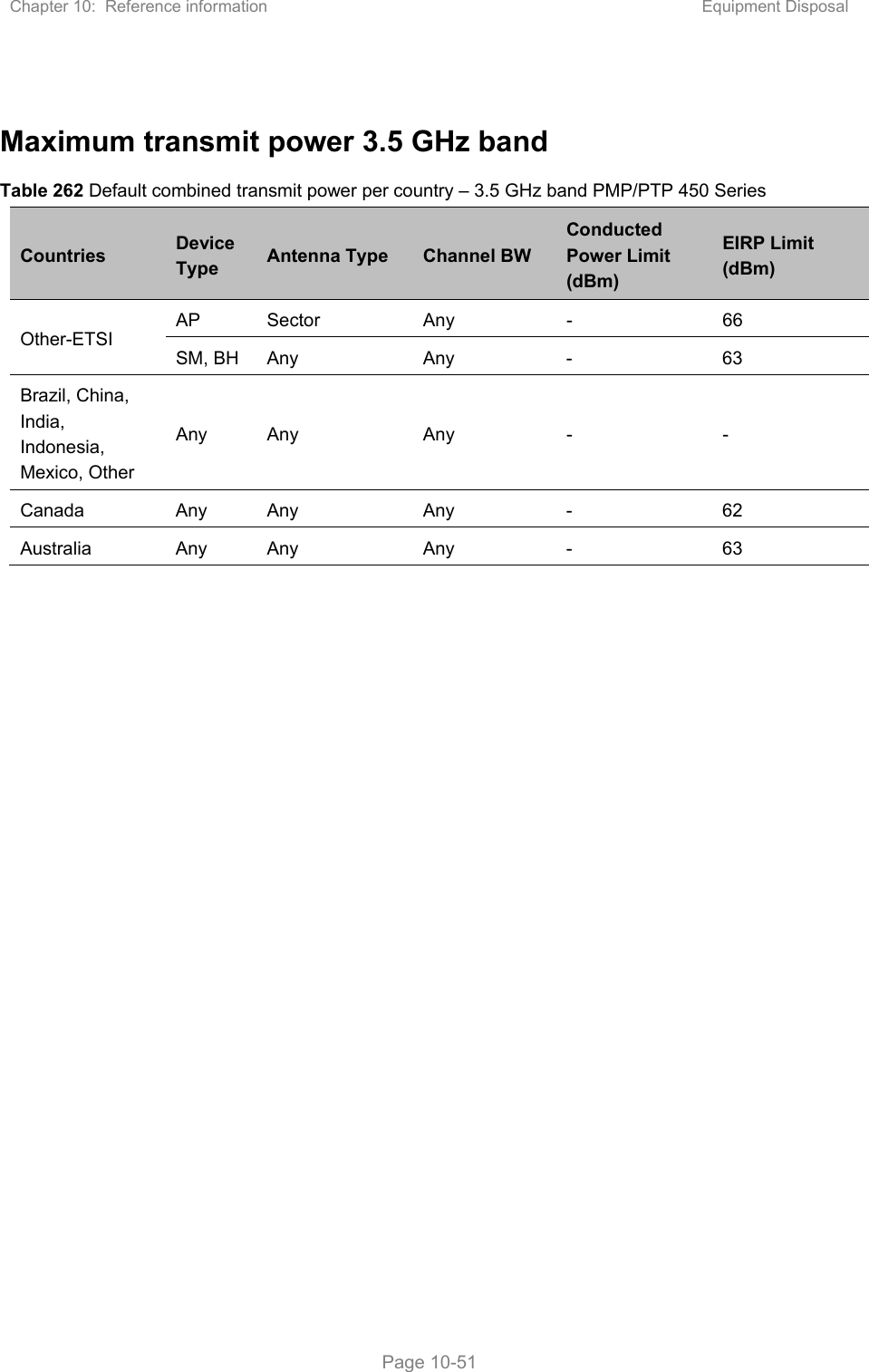
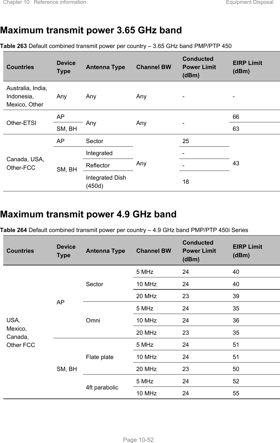
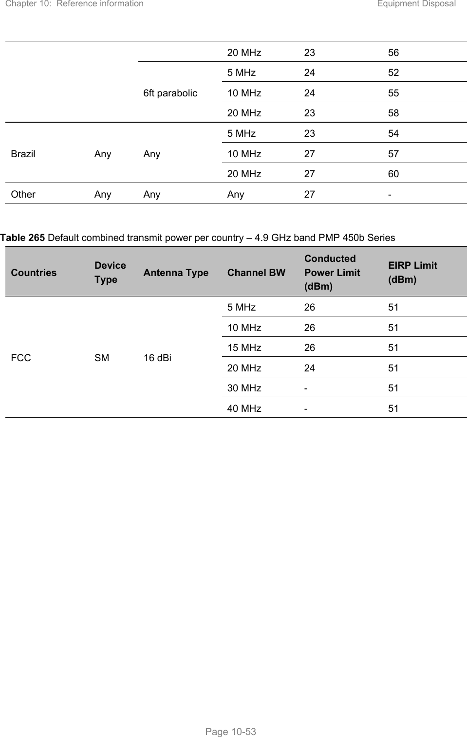
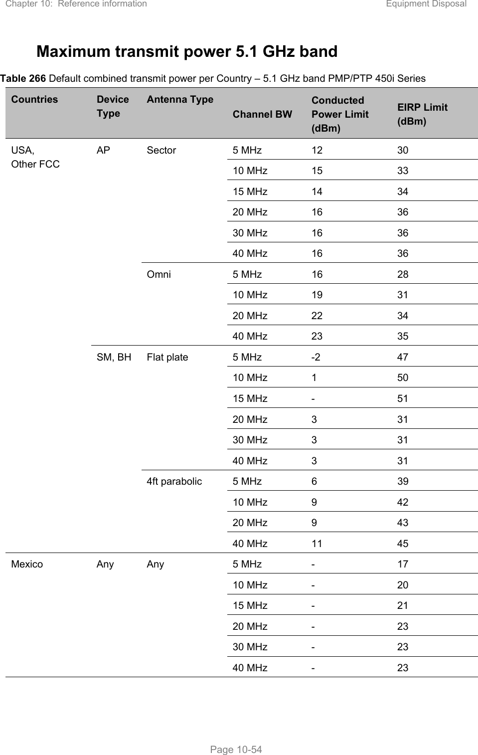
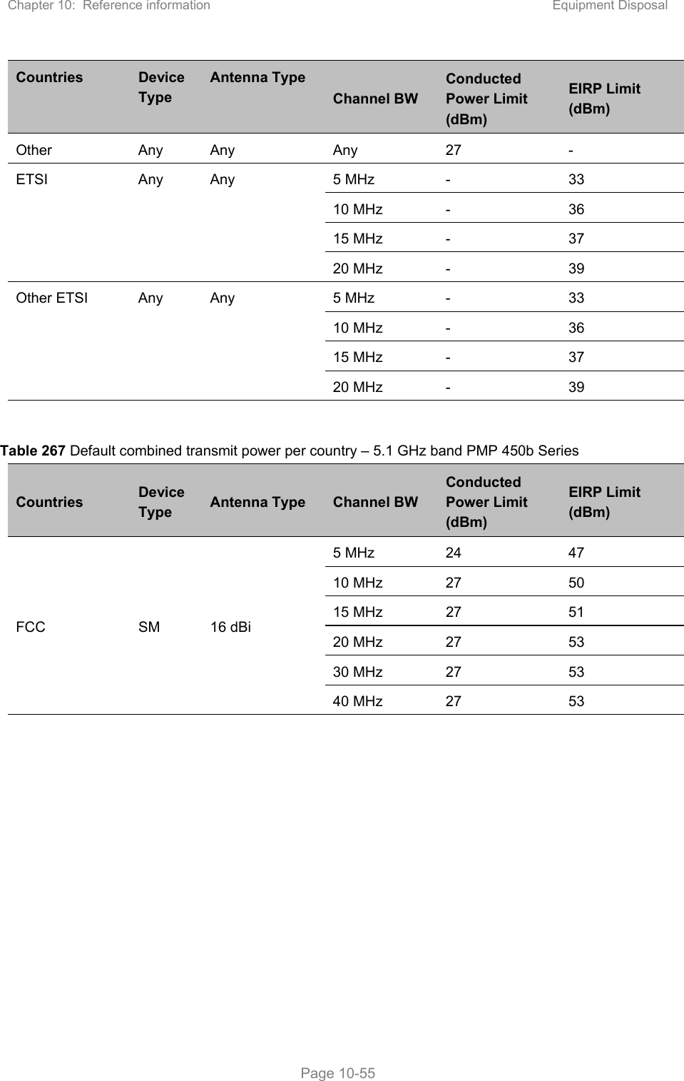
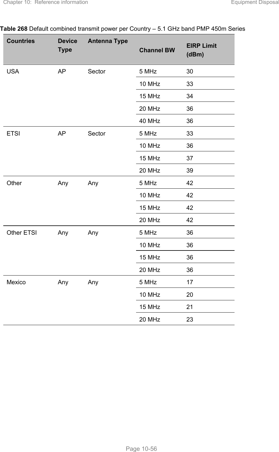
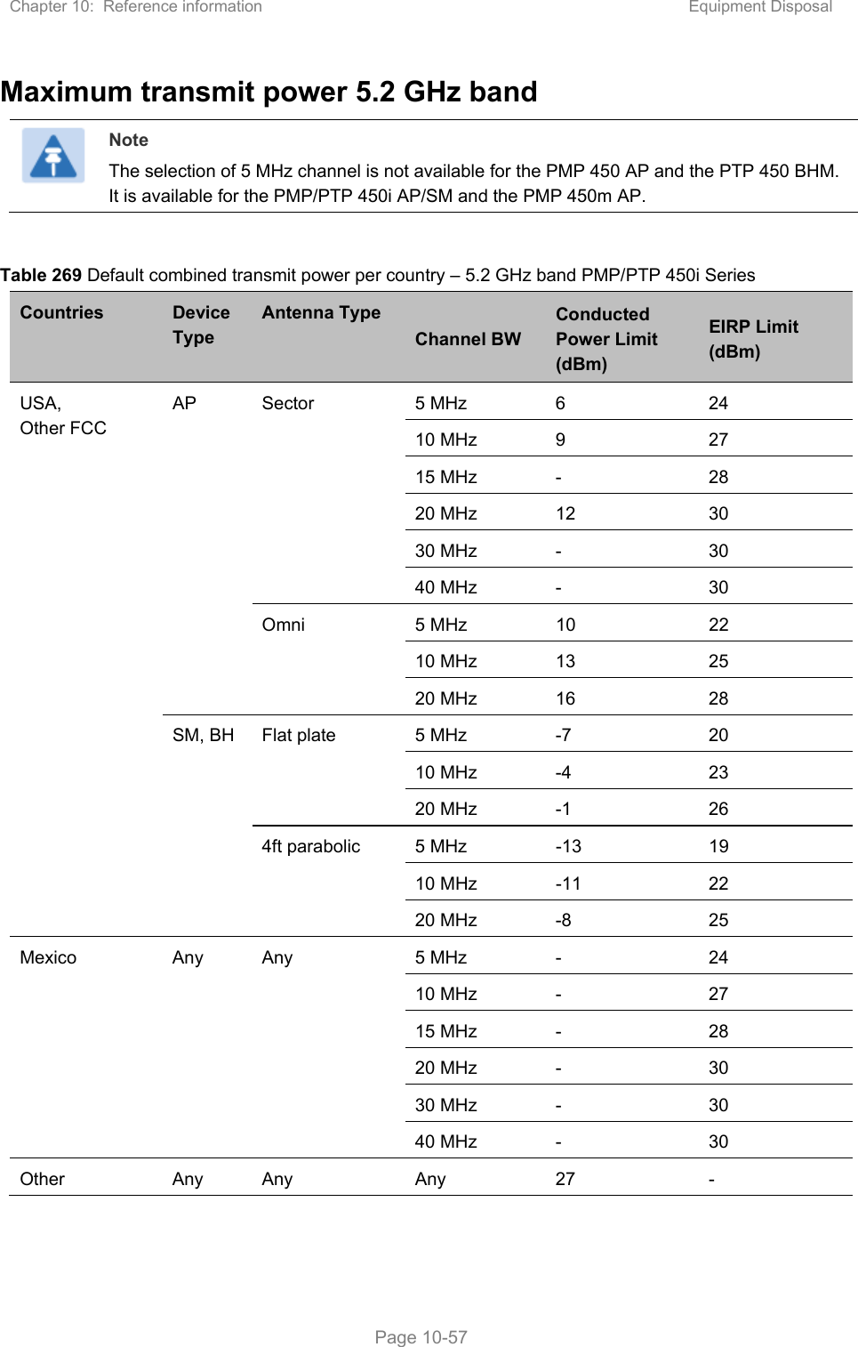
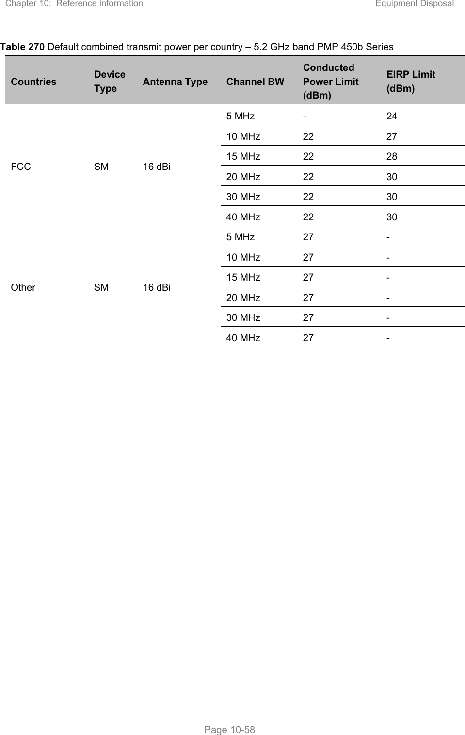
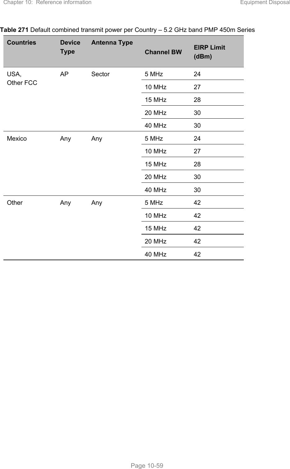
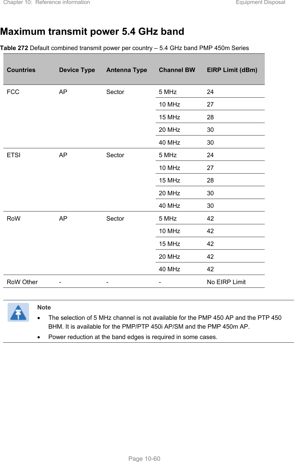
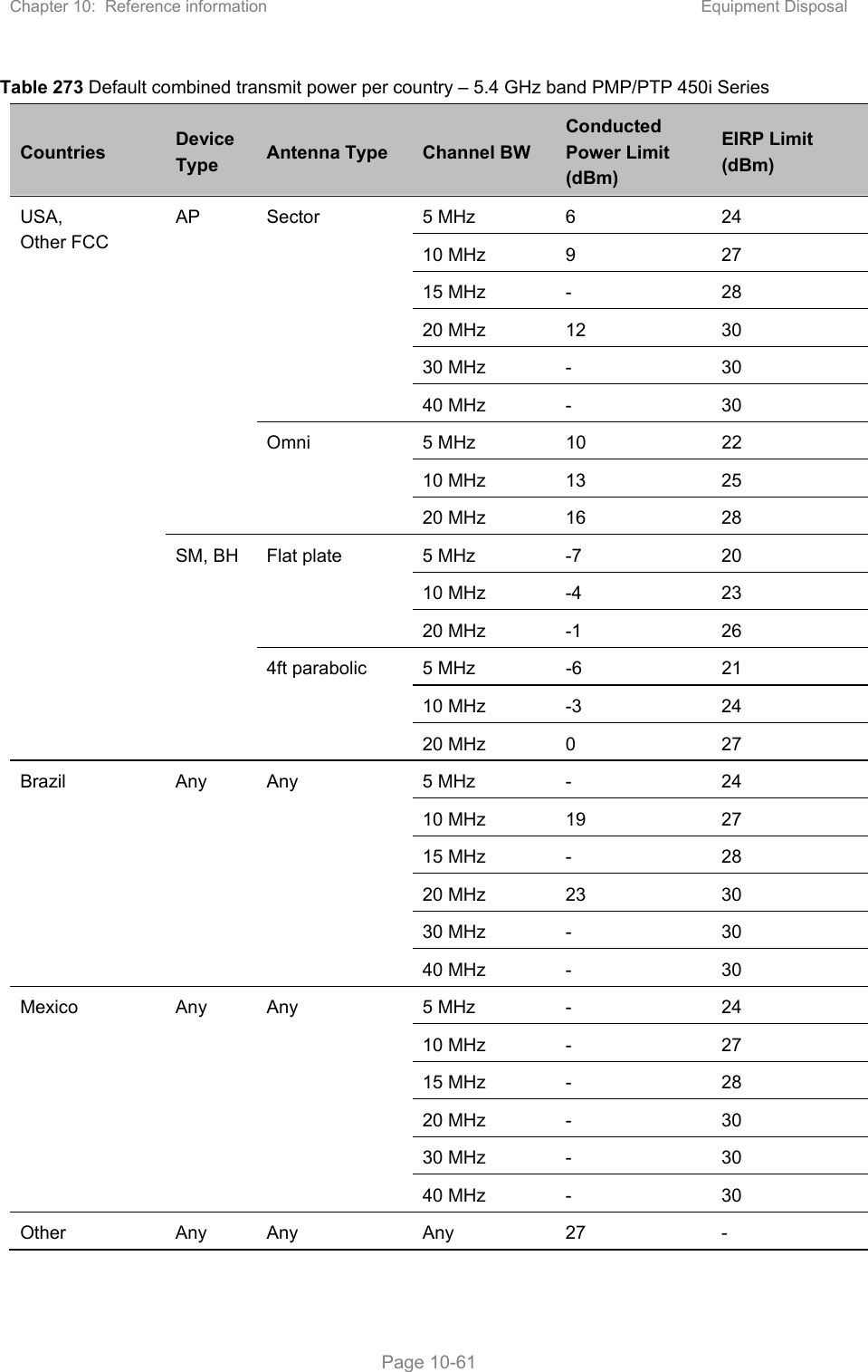
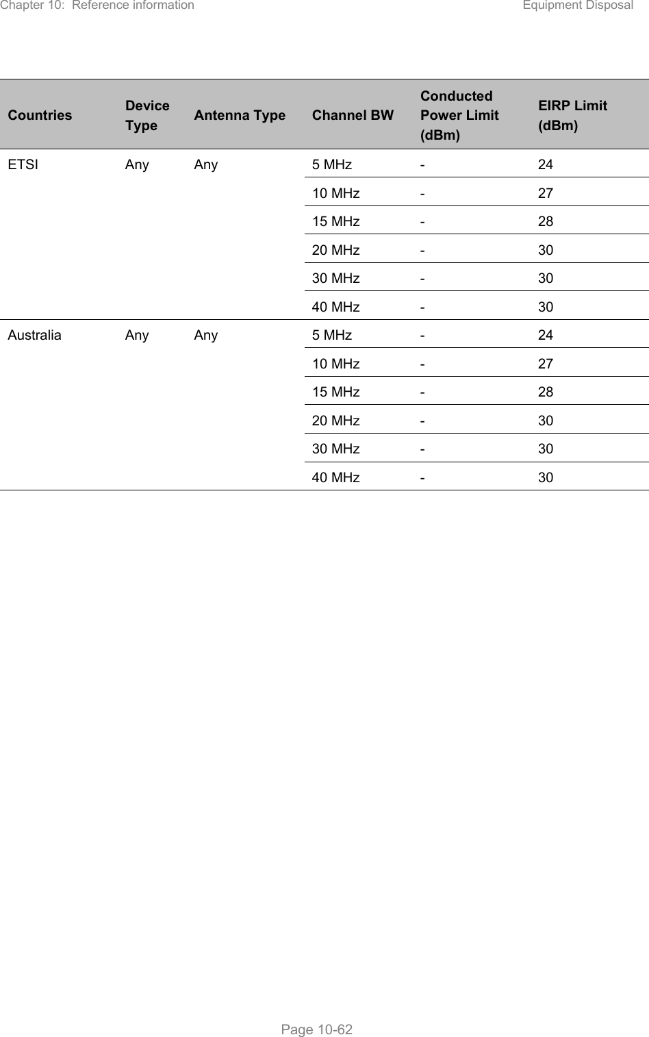
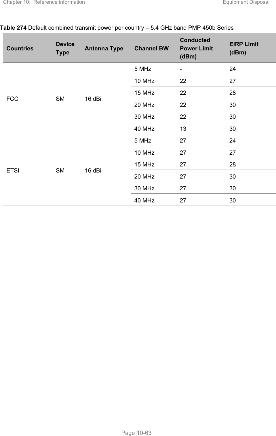
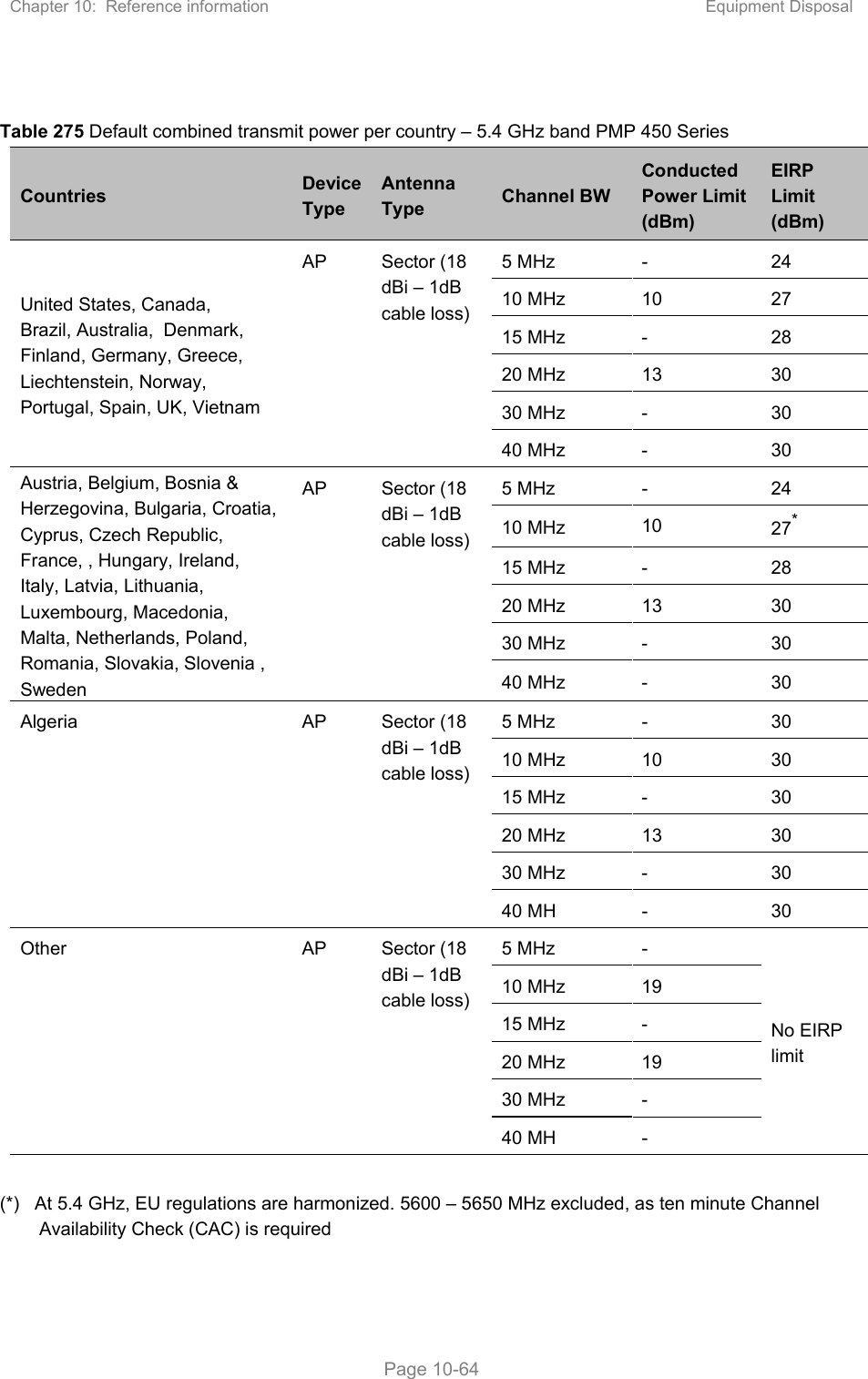
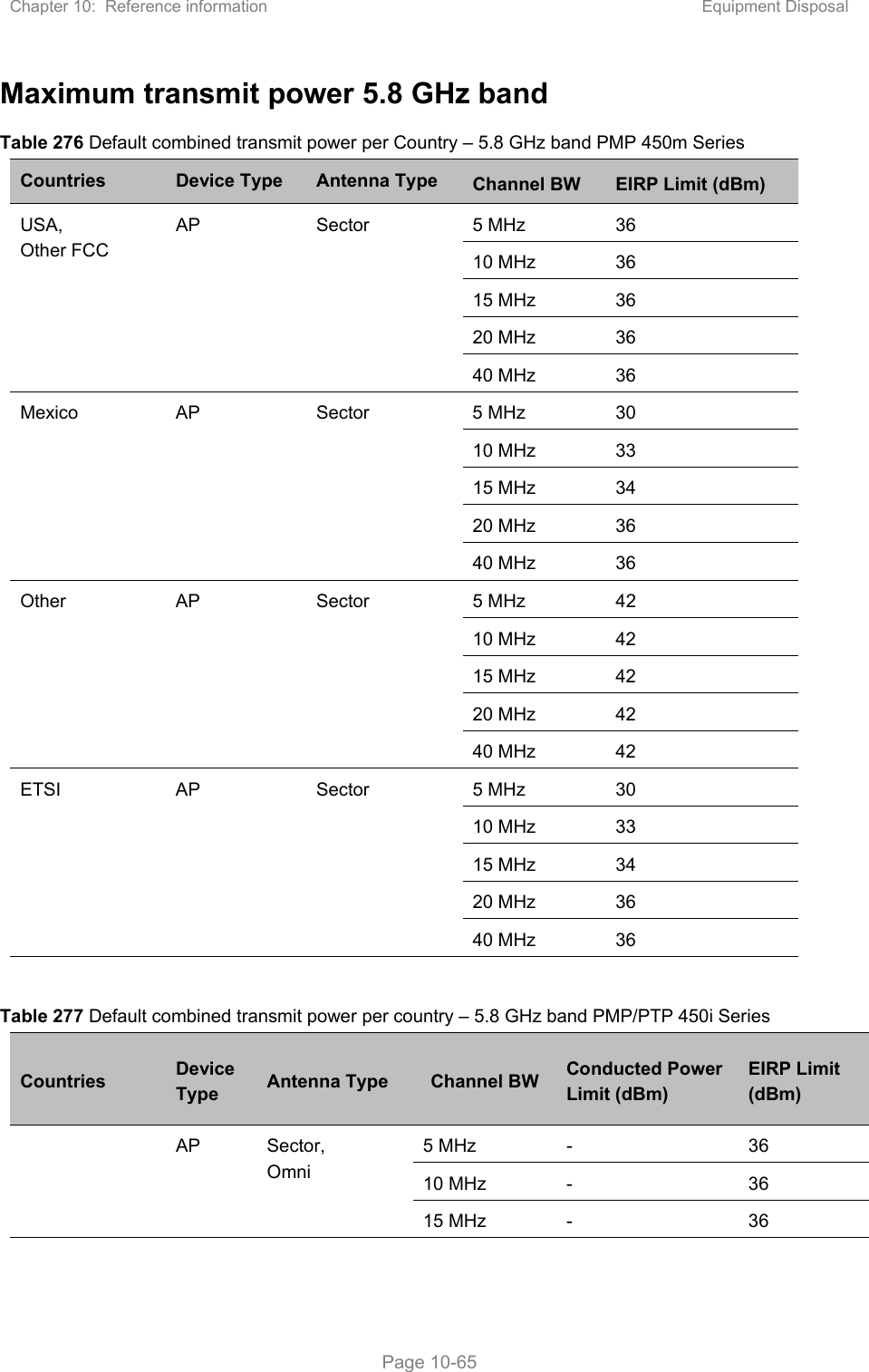
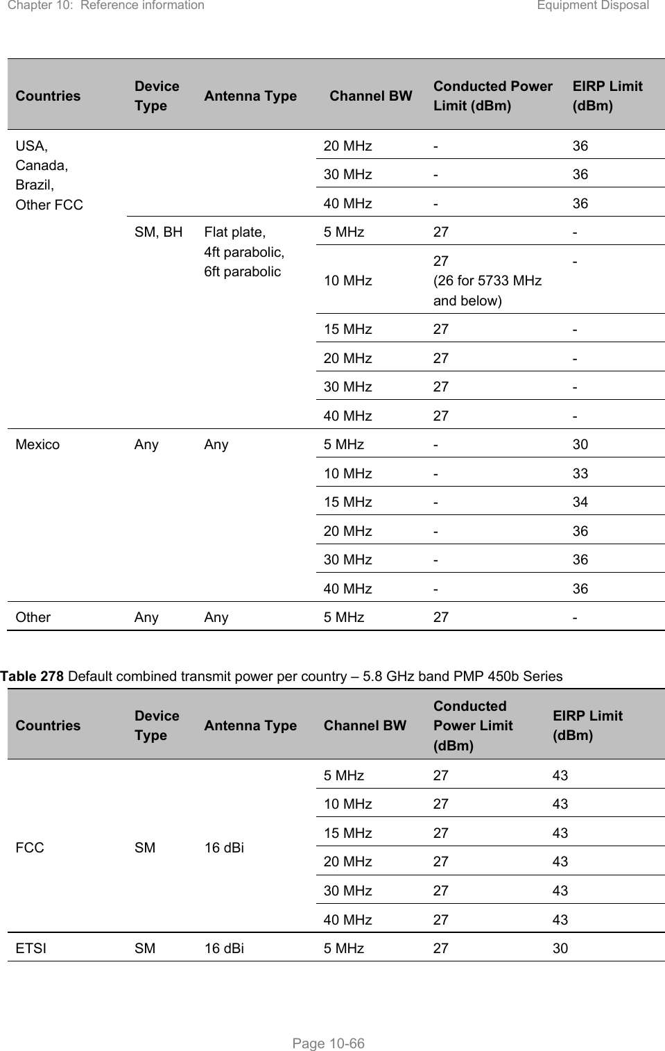
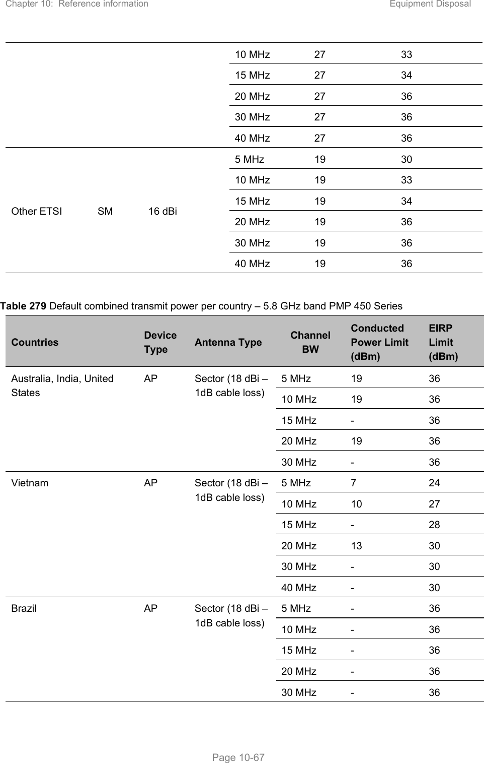
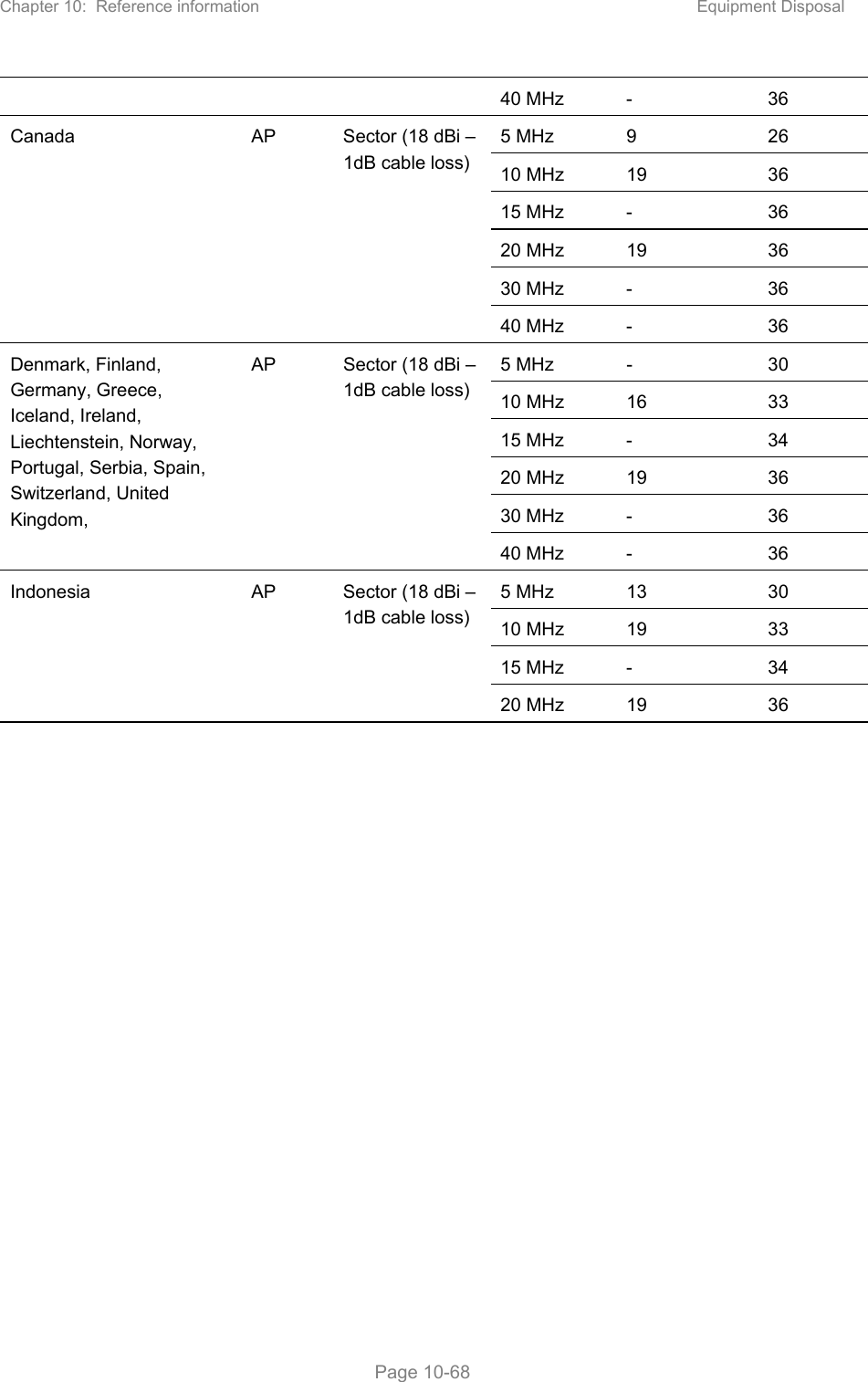
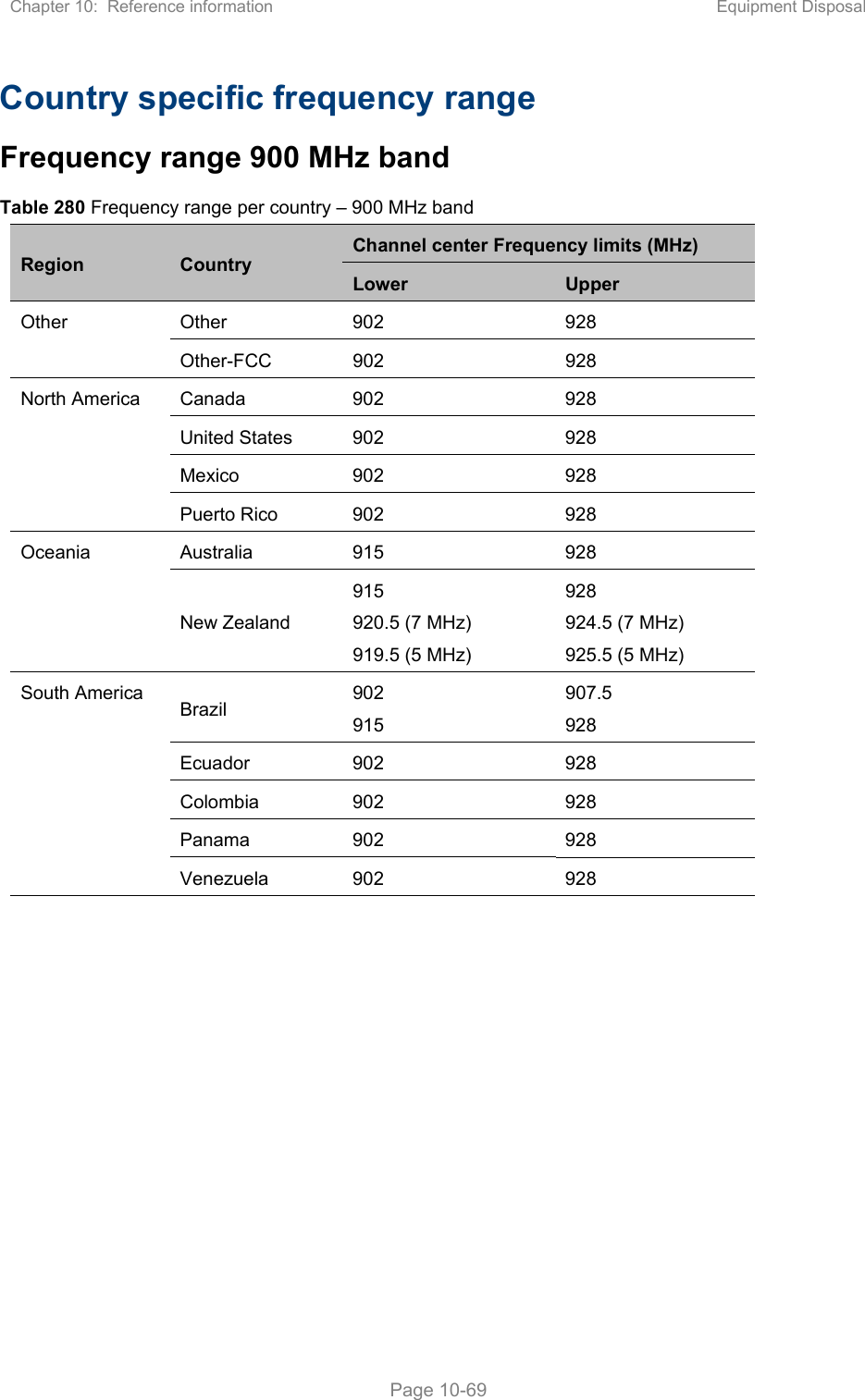
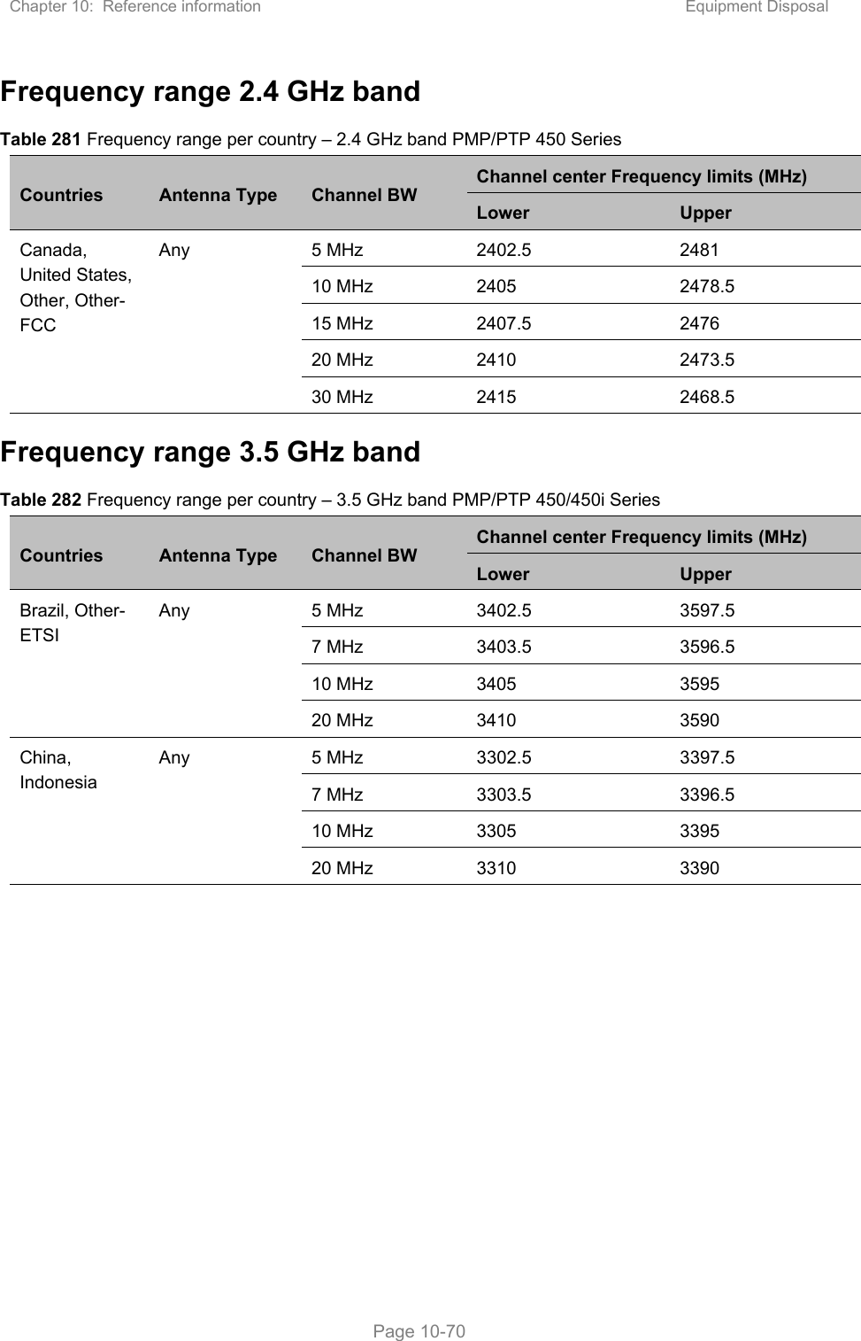
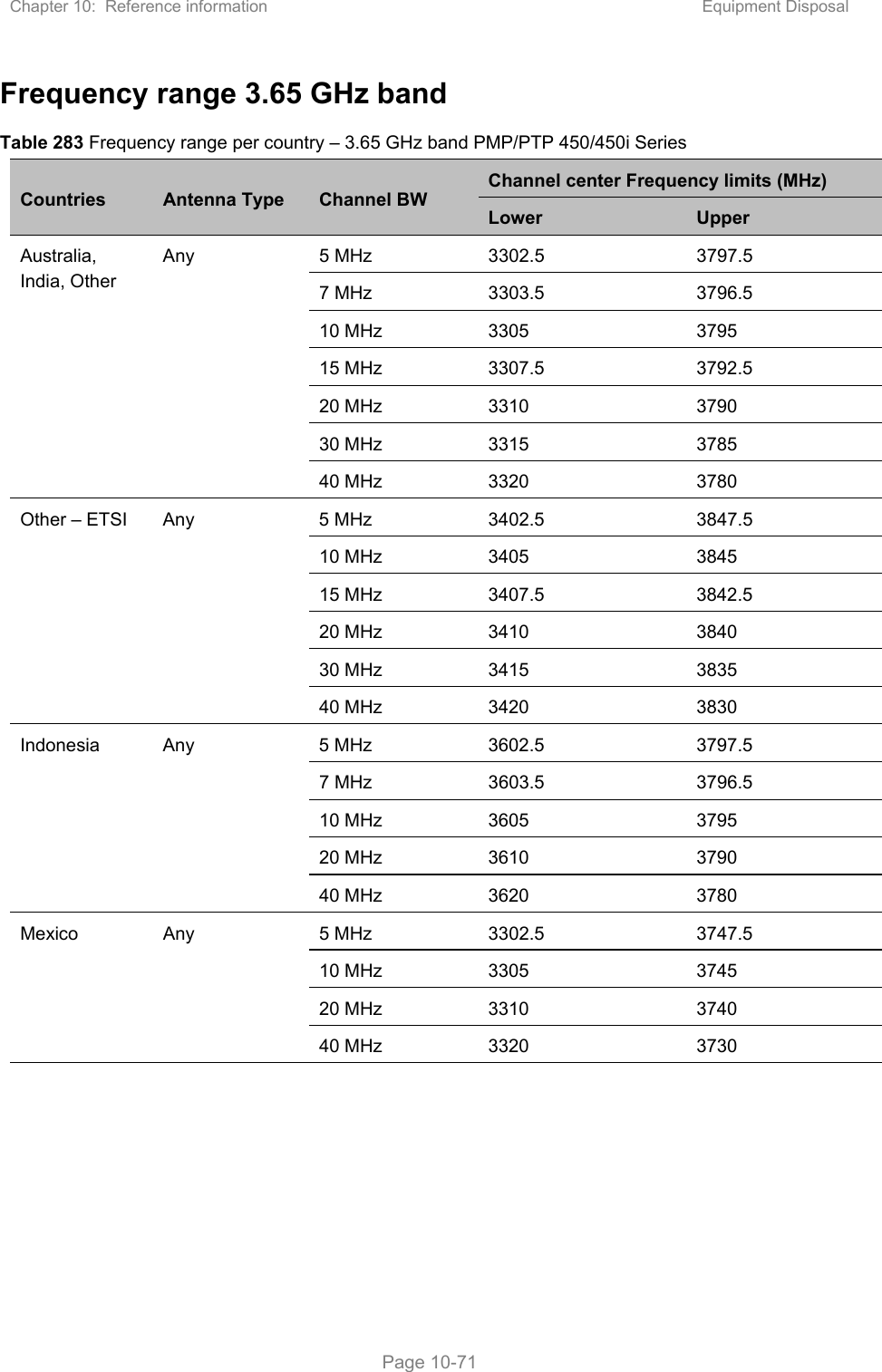
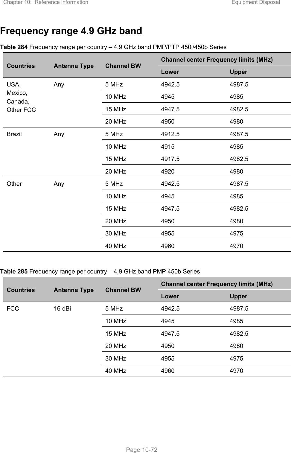
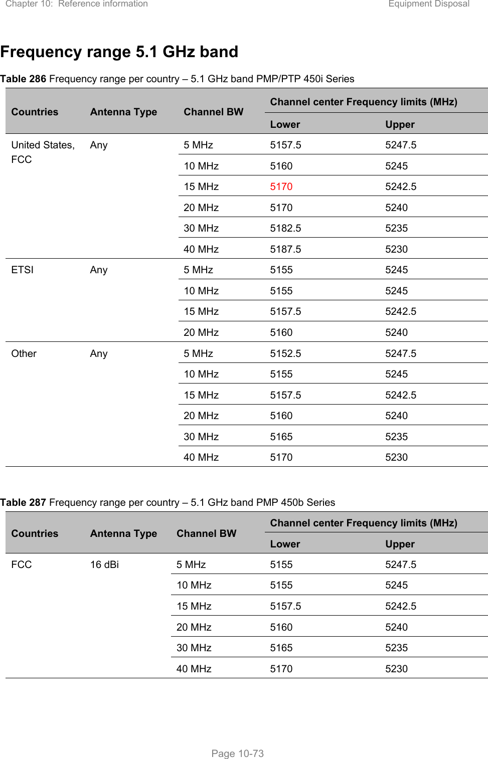
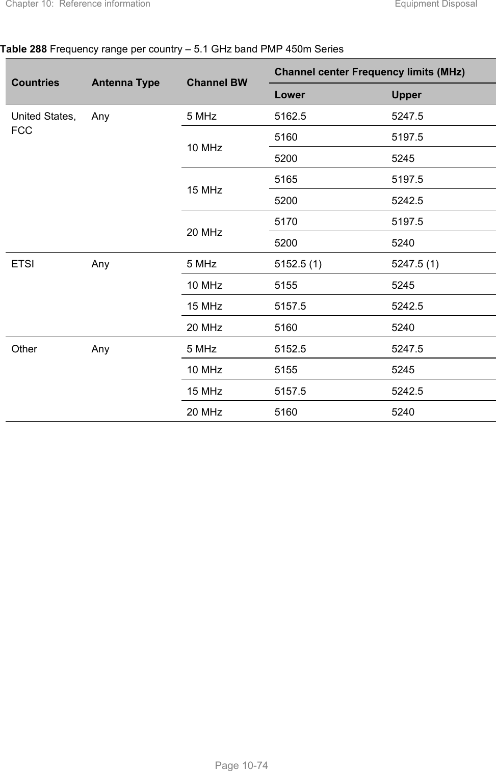
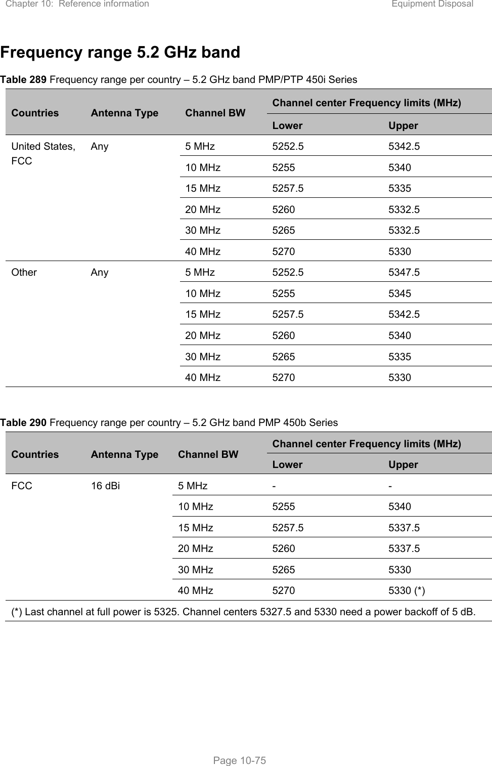
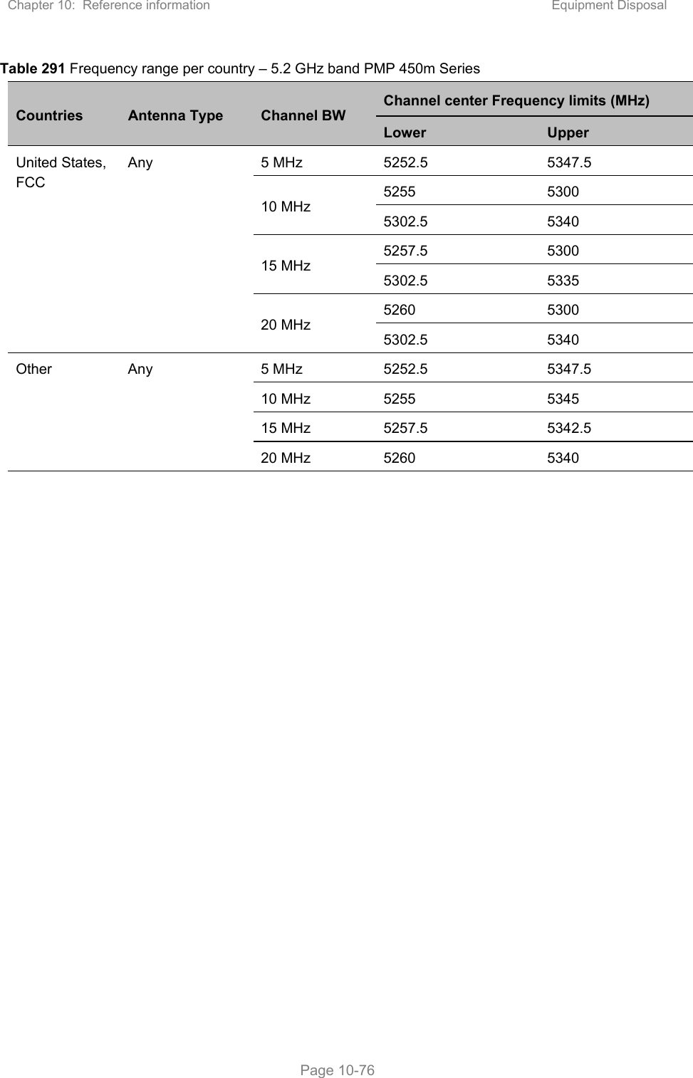
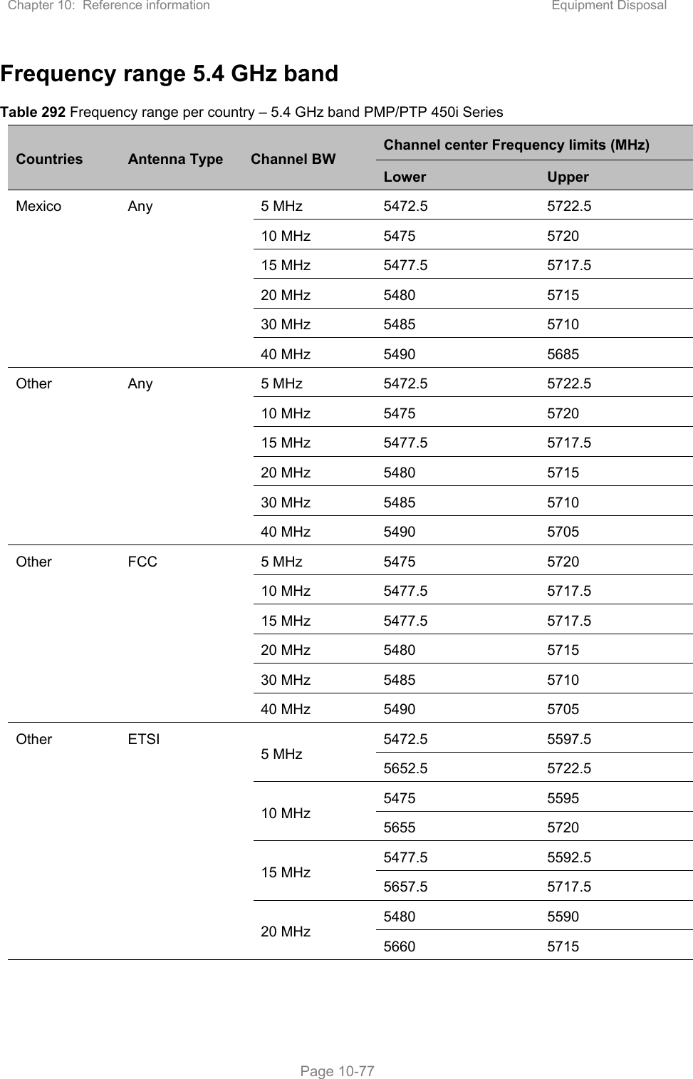
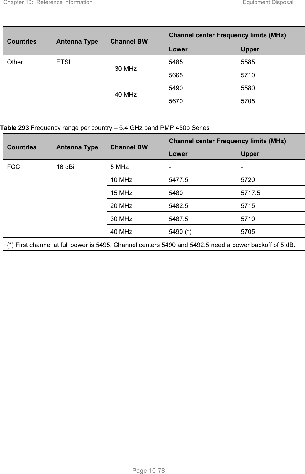
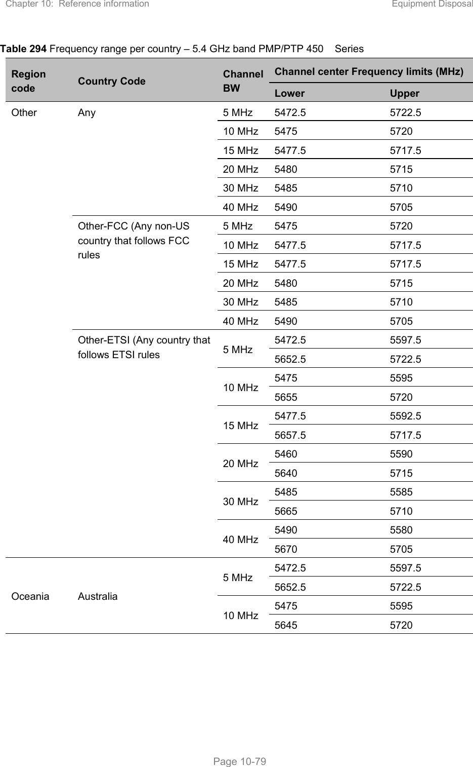
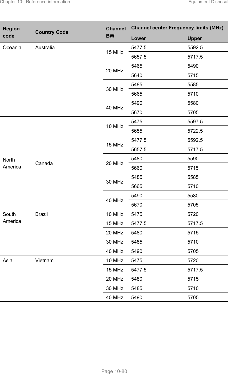
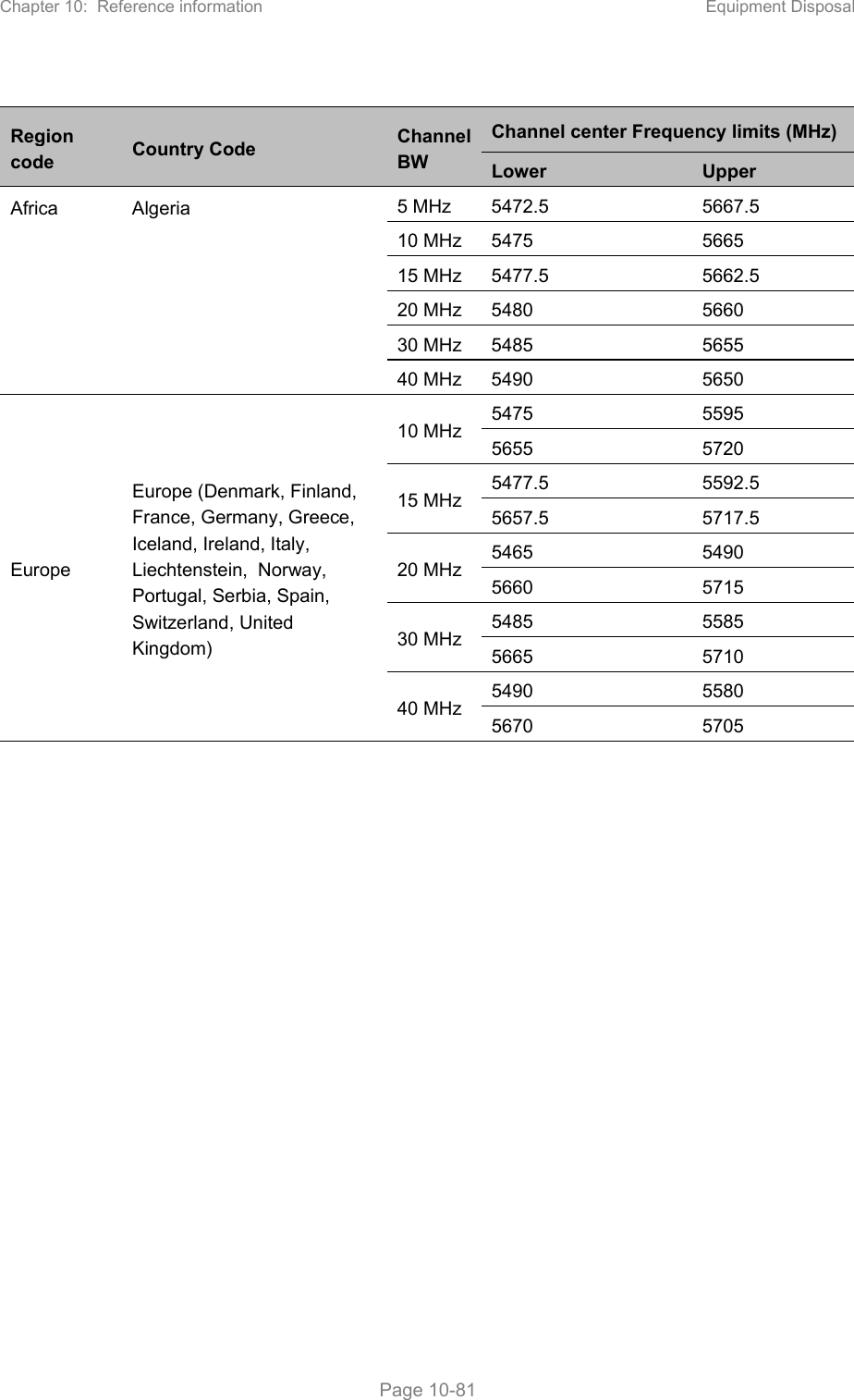
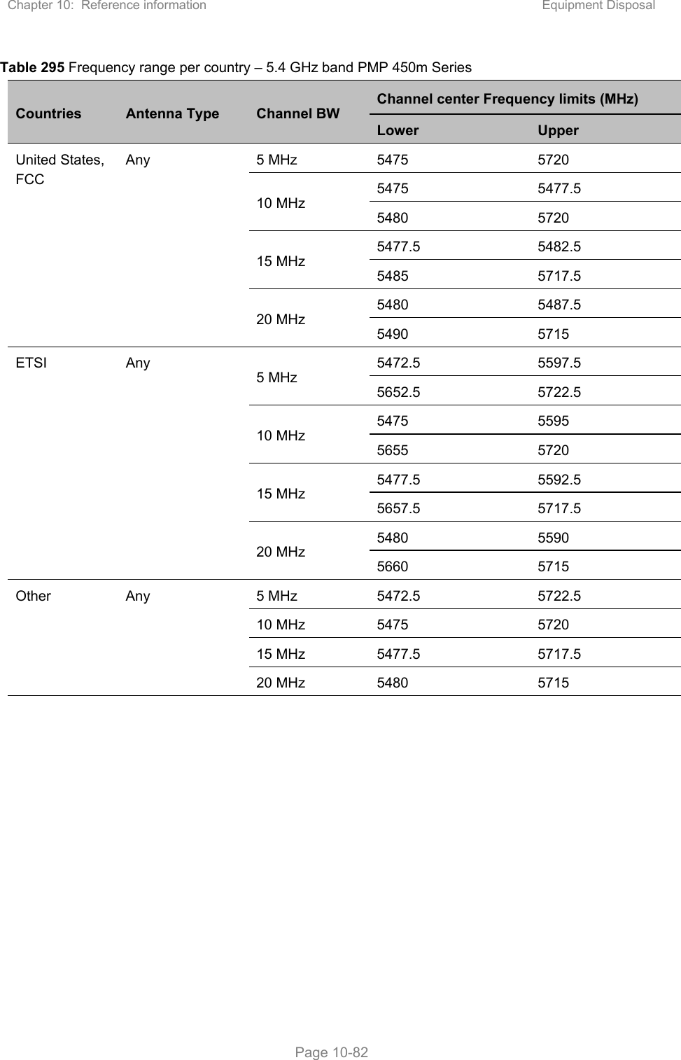
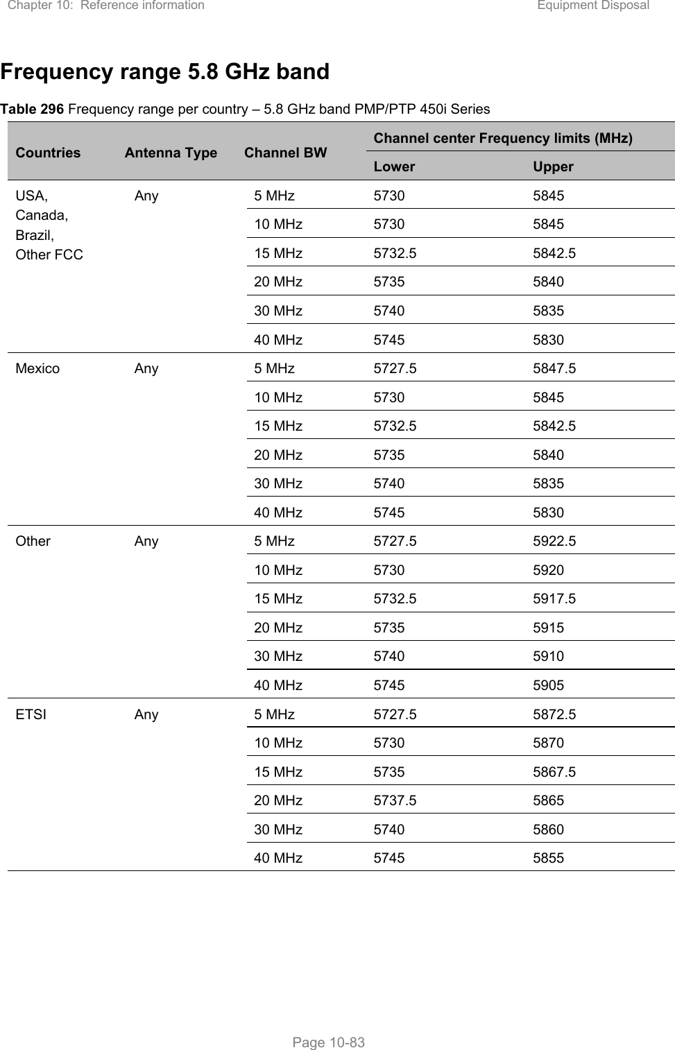
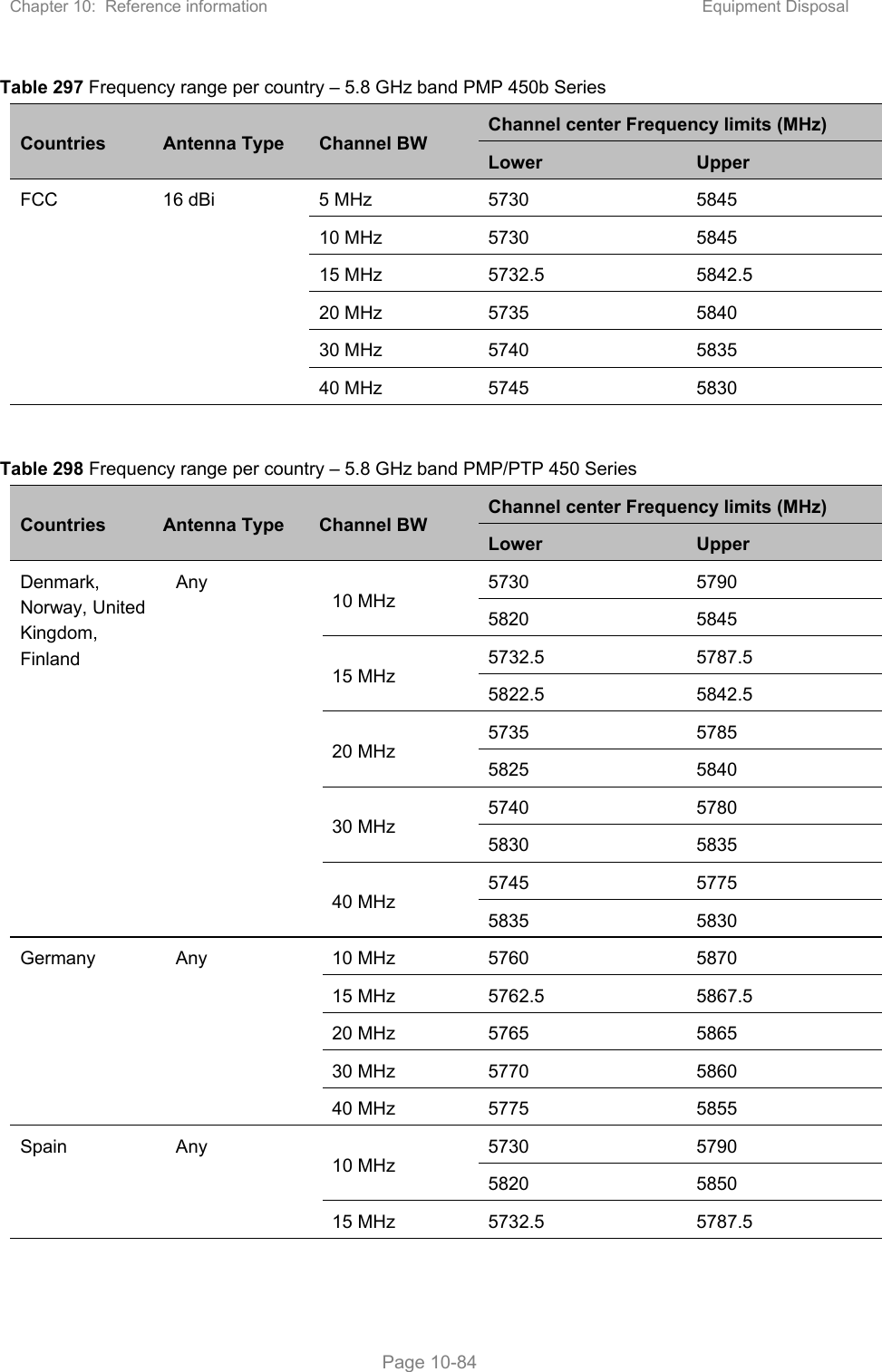
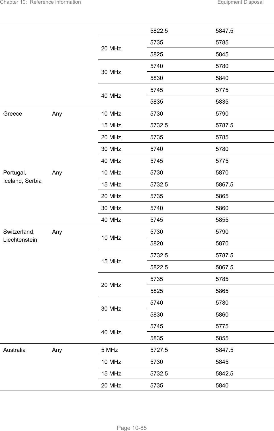
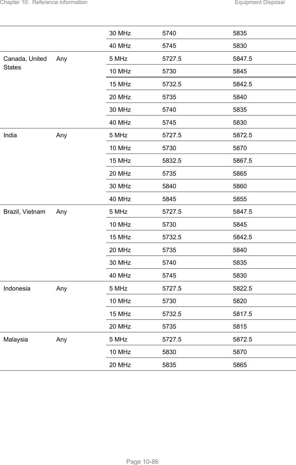
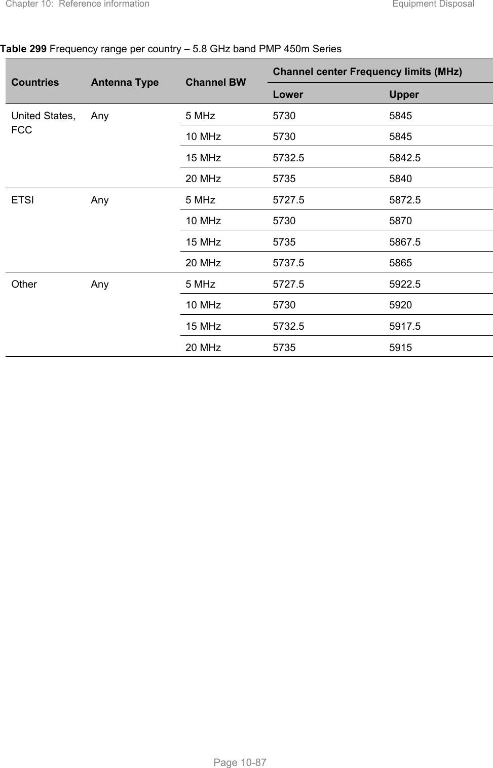
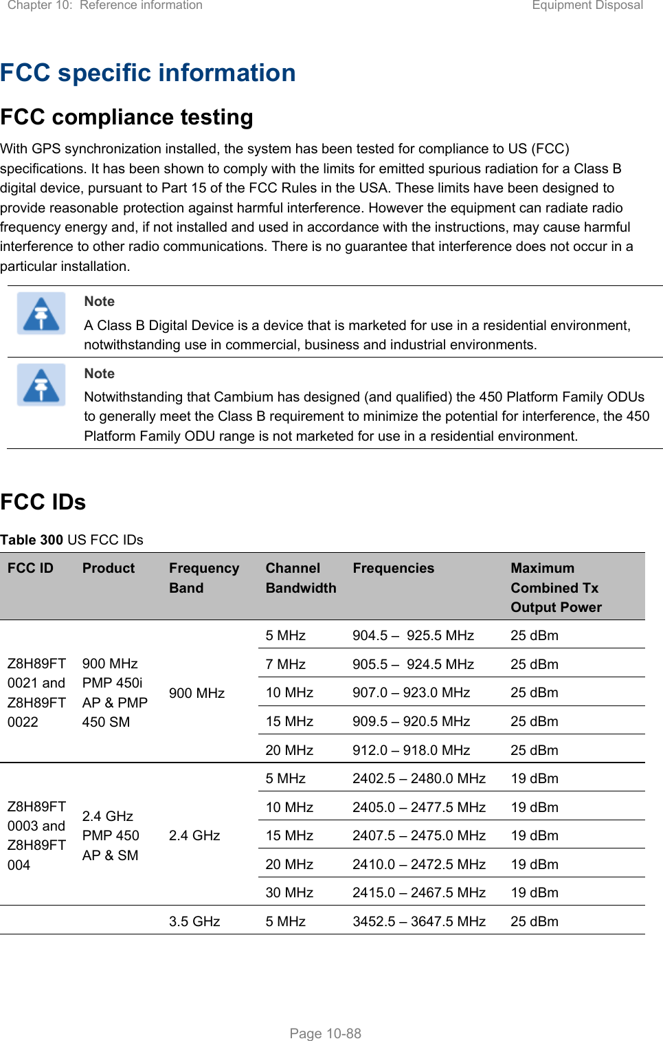
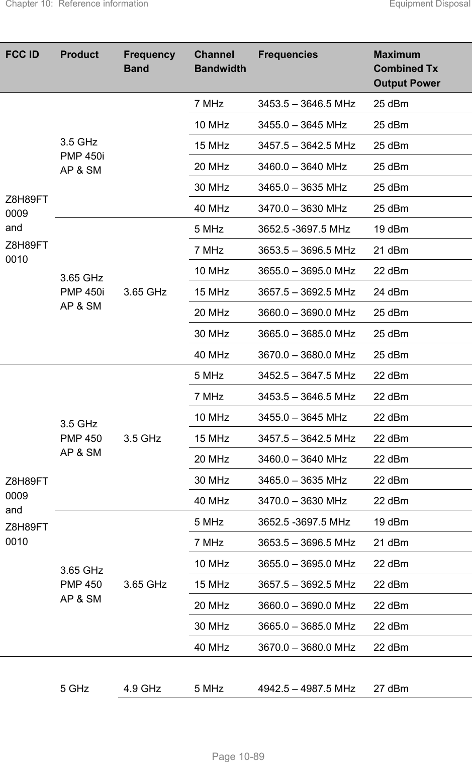
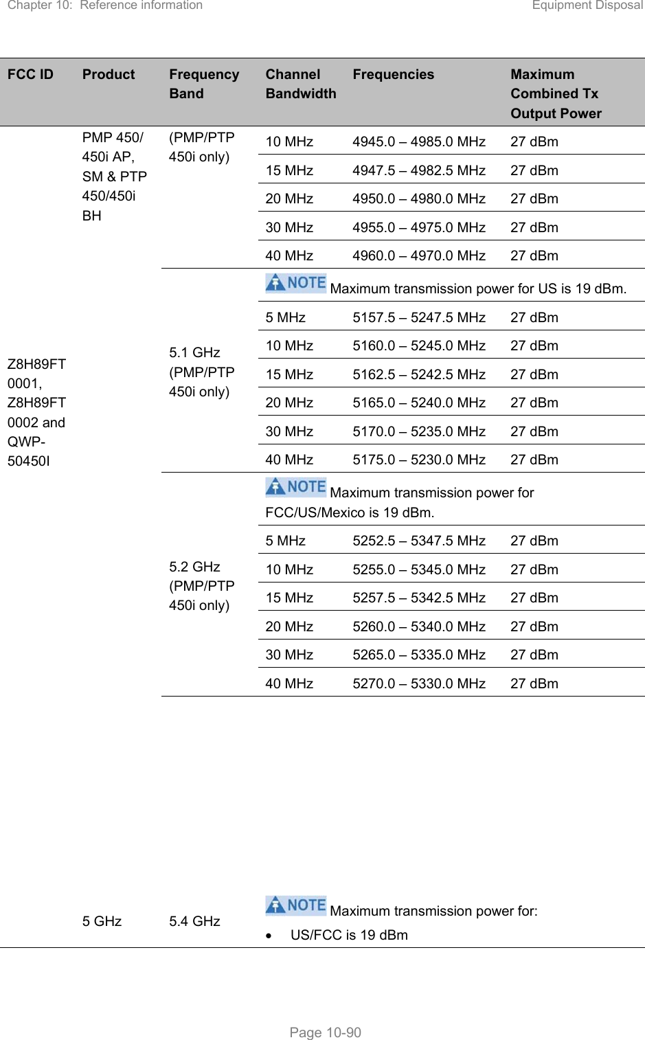
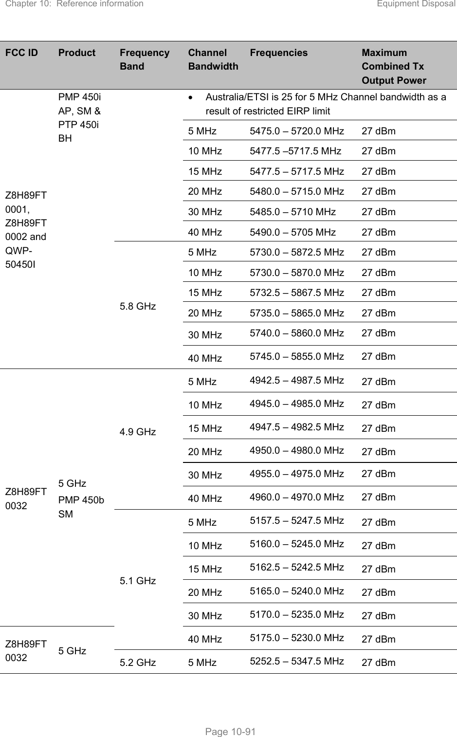
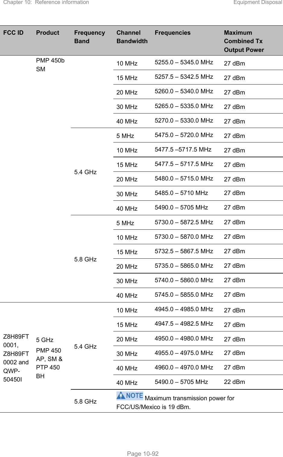
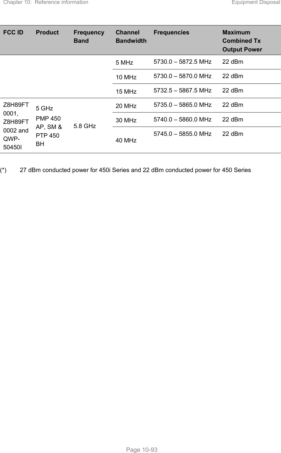
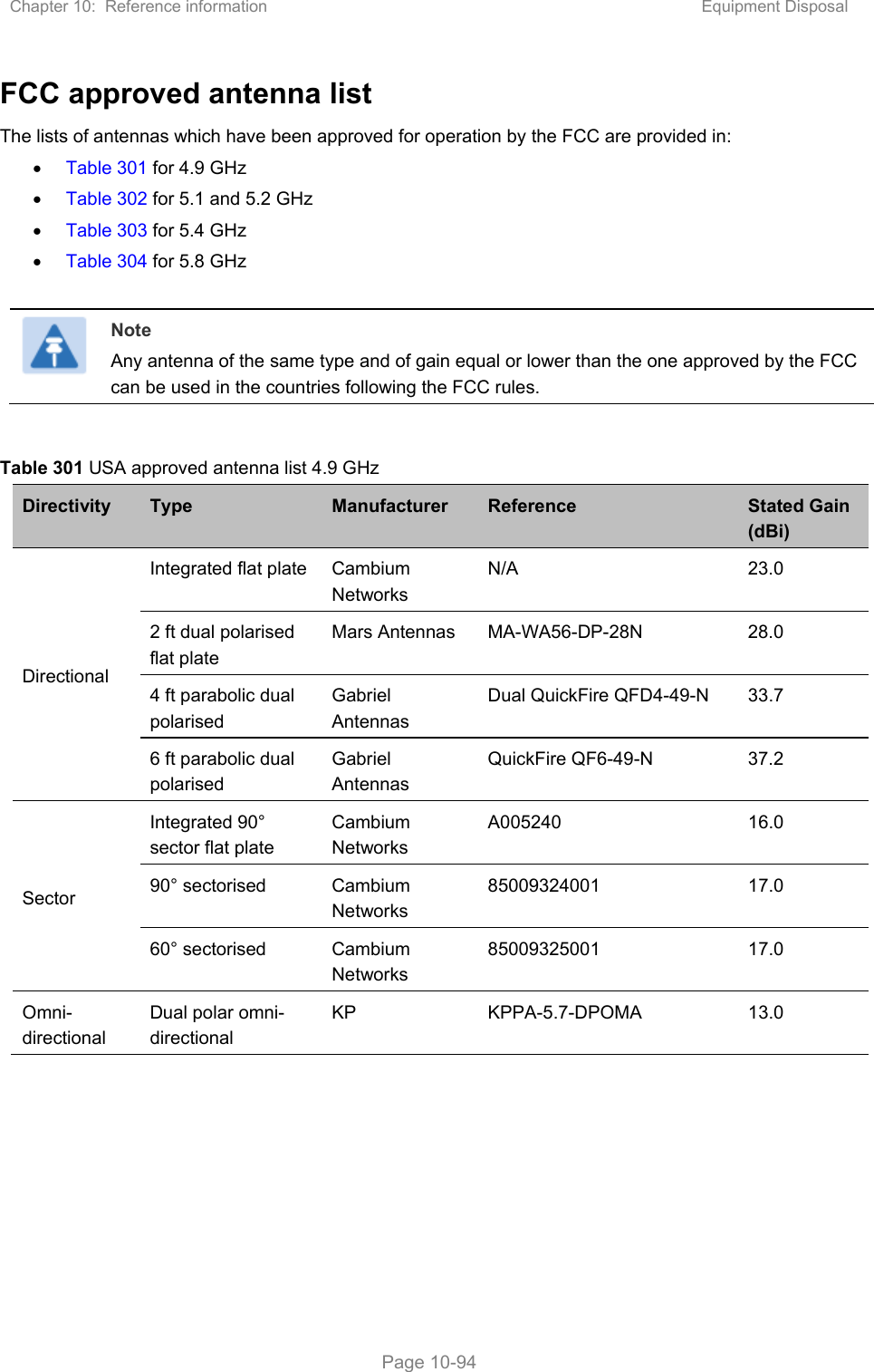
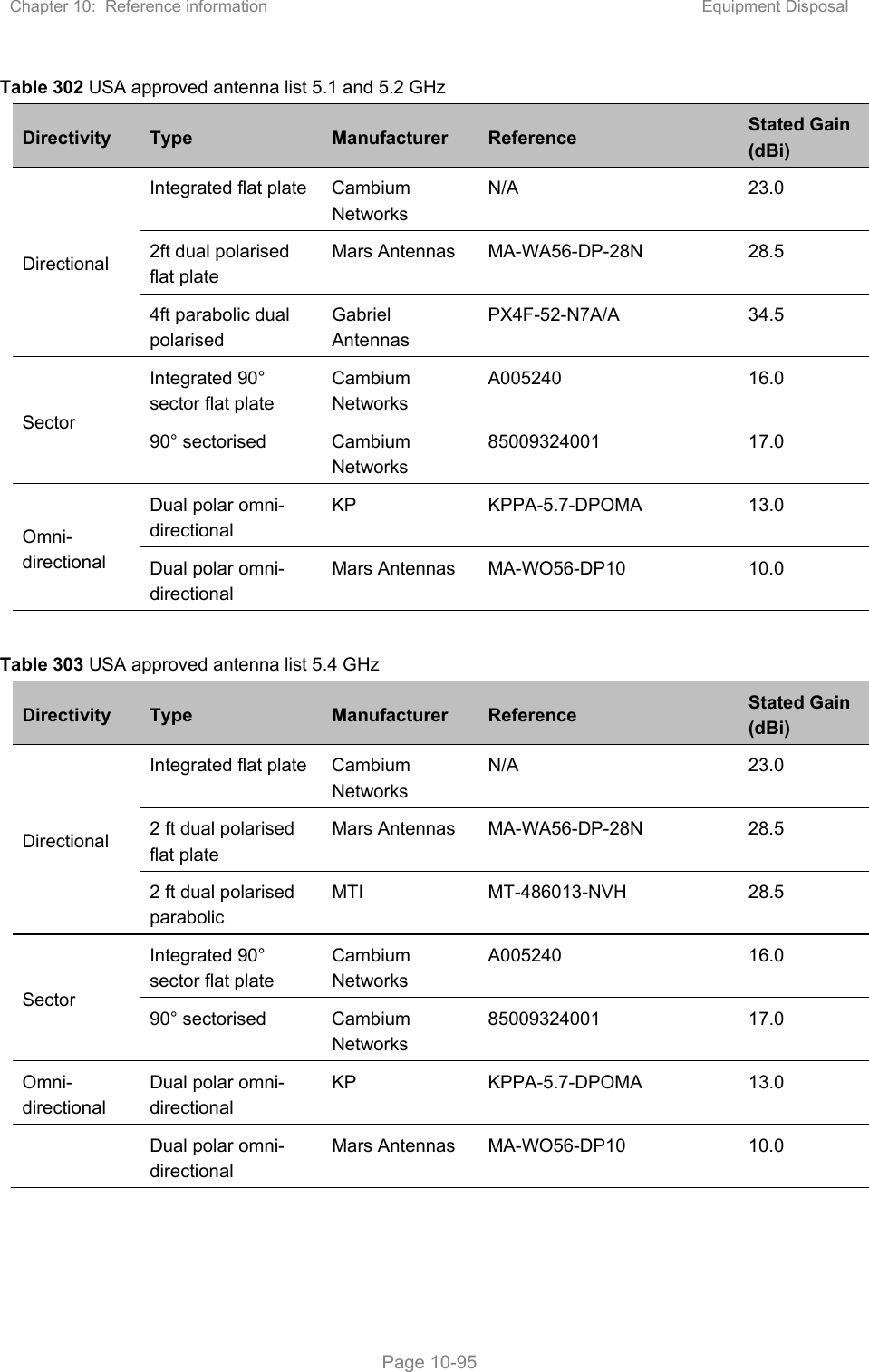
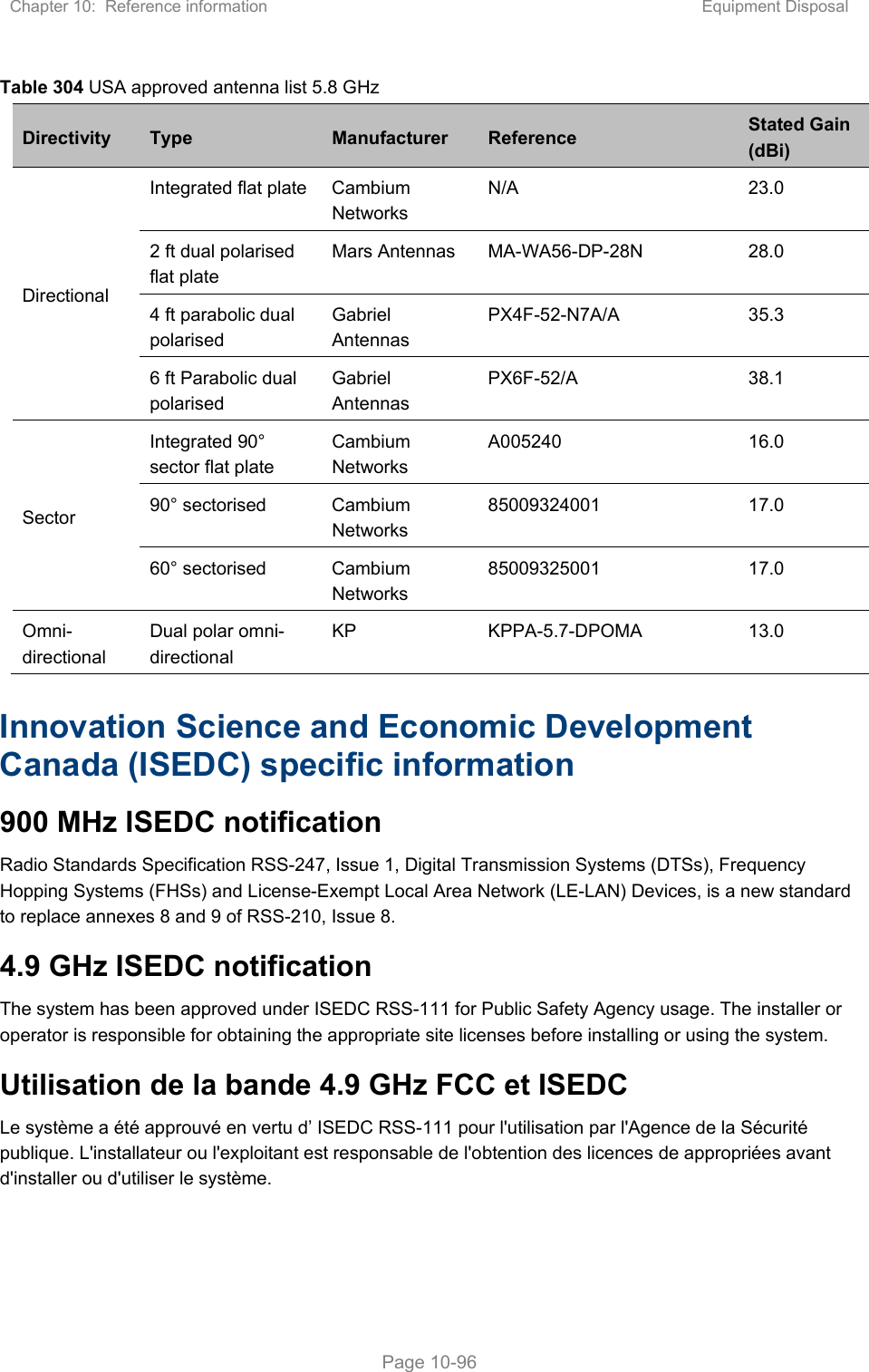
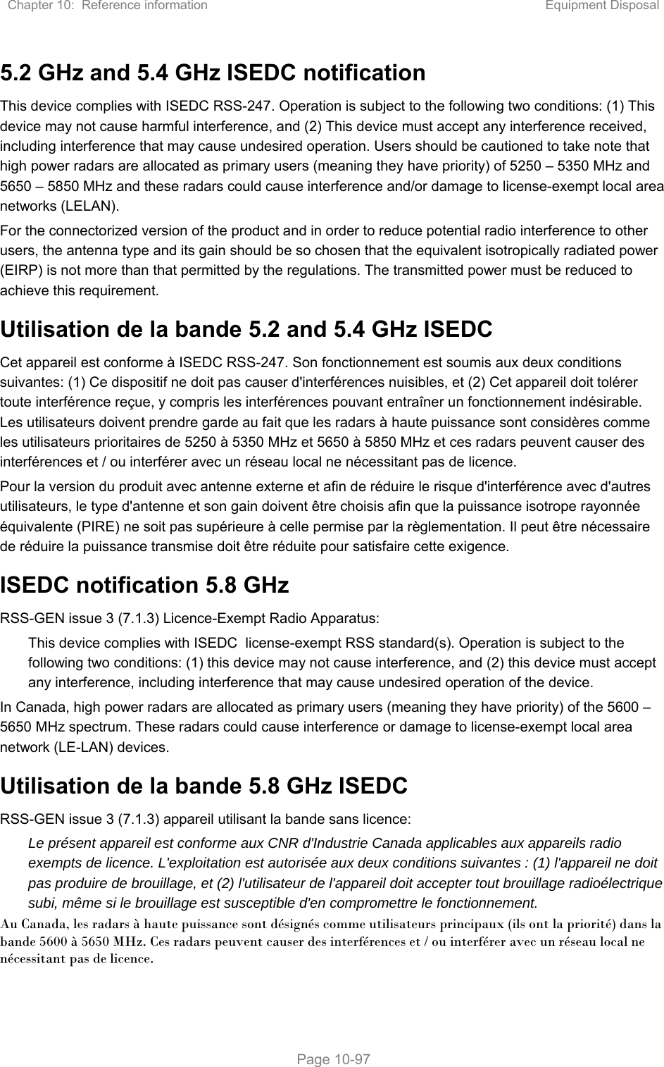
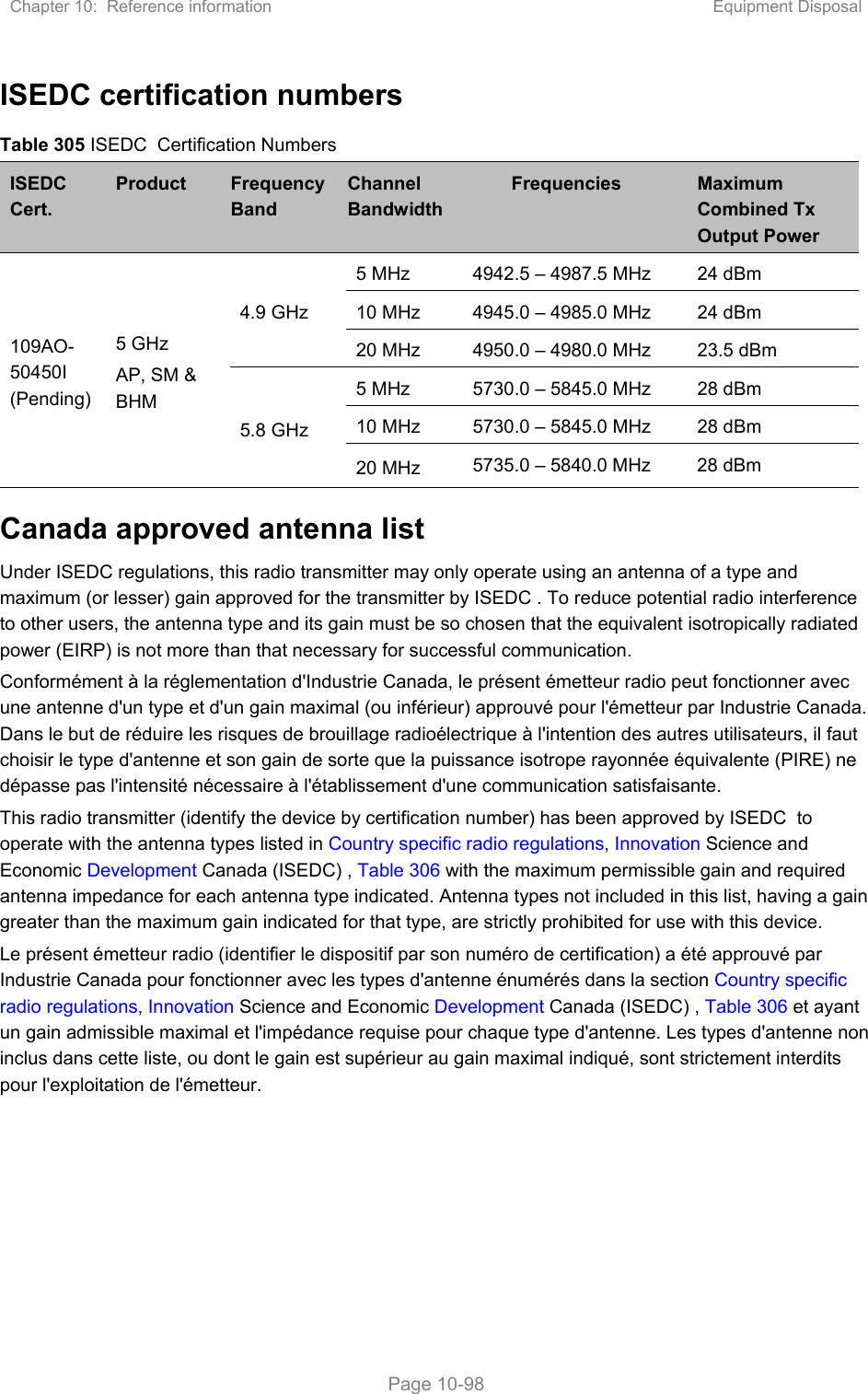
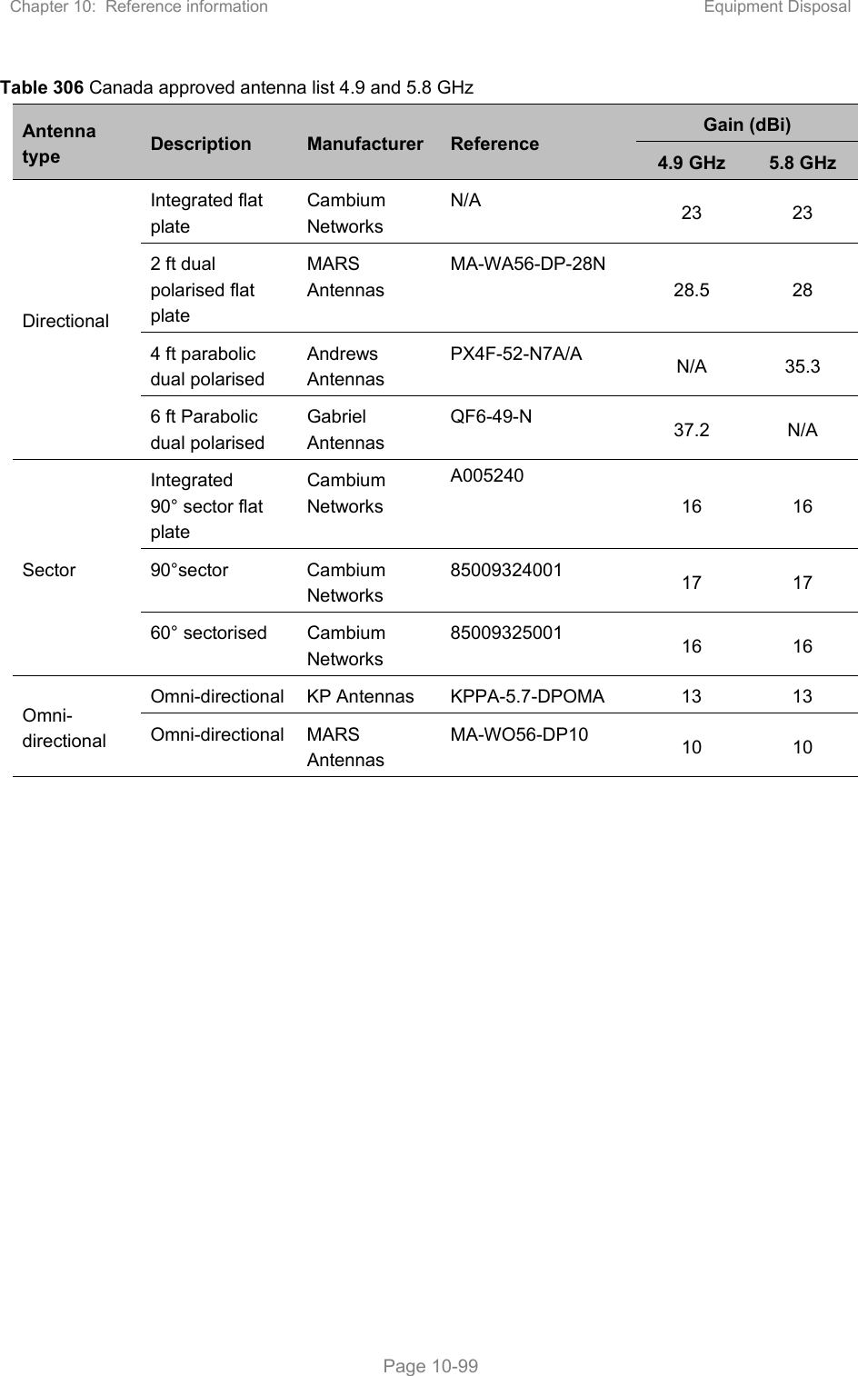
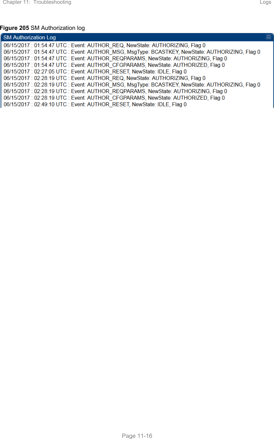
USERS MANUAL PART4