Cambium Networks 50450M 5 GHz Point to Multipoint User MIMO Accesspoint User Manual 450 Platform User Guide
Cambium Networks Limited 5 GHz Point to Multipoint User MIMO Accesspoint 450 Platform User Guide
Contents
- 1. USER GUIDE P1
- 2. USER GUIDE P2
- 3. USER GUIDE P3
- 4. USER GUIDE P4
- 5. User manual
- 6. User Manual
- 7. USERS MANUAL PART1
- 8. USERS MANUAL PART2
- 9. USERS MANUAL PART3
- 10. USERS MANUAL PART4
- 11. USER MANUAL PART1
- 12. USER MANUAL PART2
- 13. USER MANUAL PART 3
- 14. USER MANUAL PART 4
- 15. USER MANUAL PT1
- 16. USER MANUAL PT2
- 17. USER MANUAL PT3
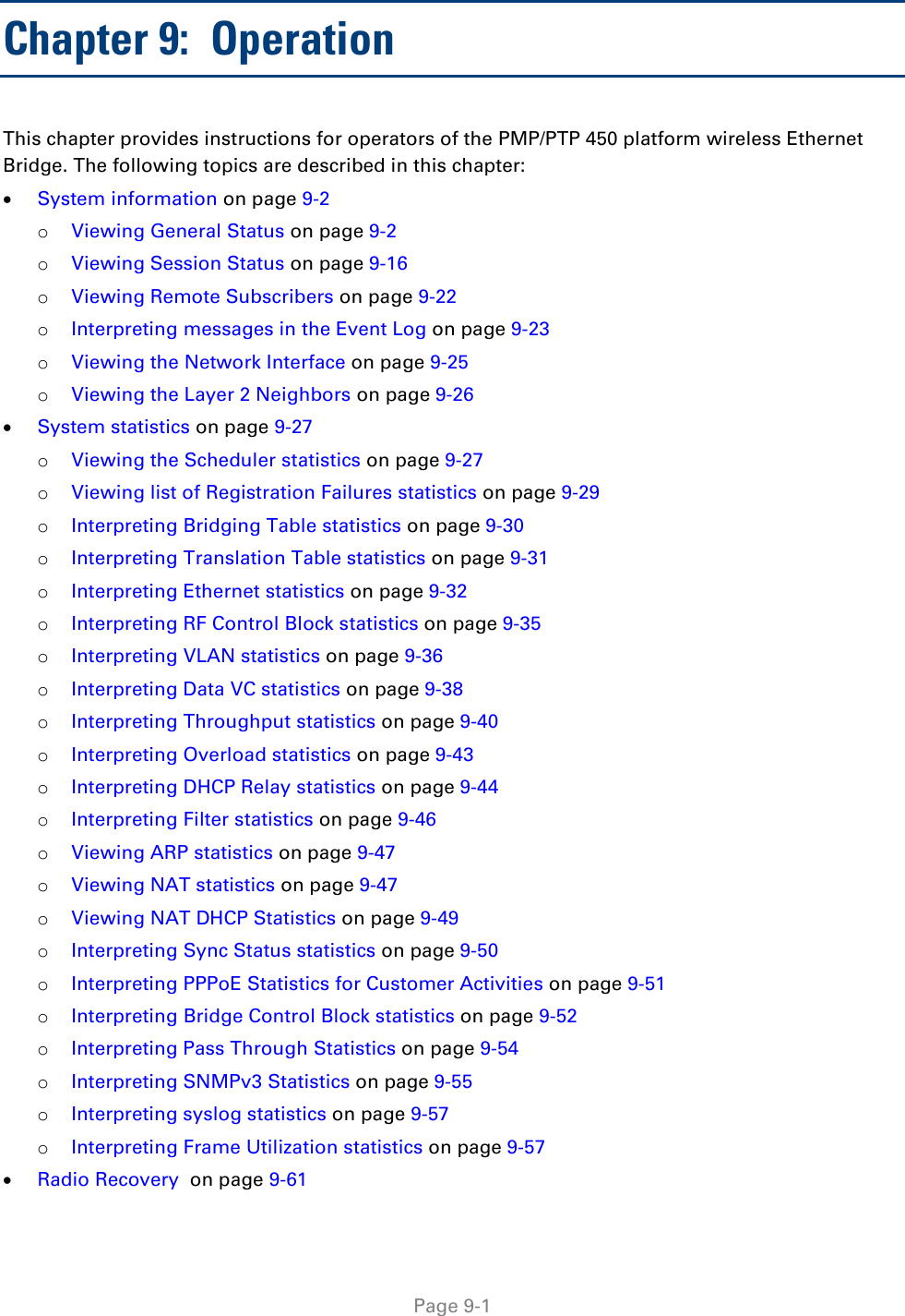
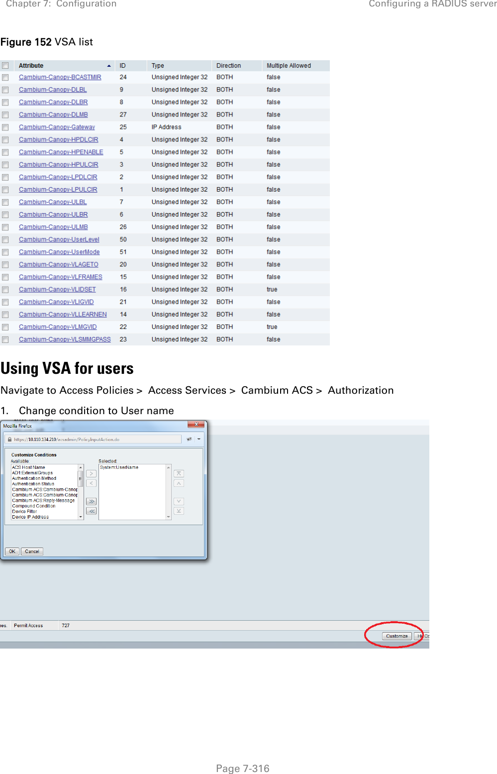
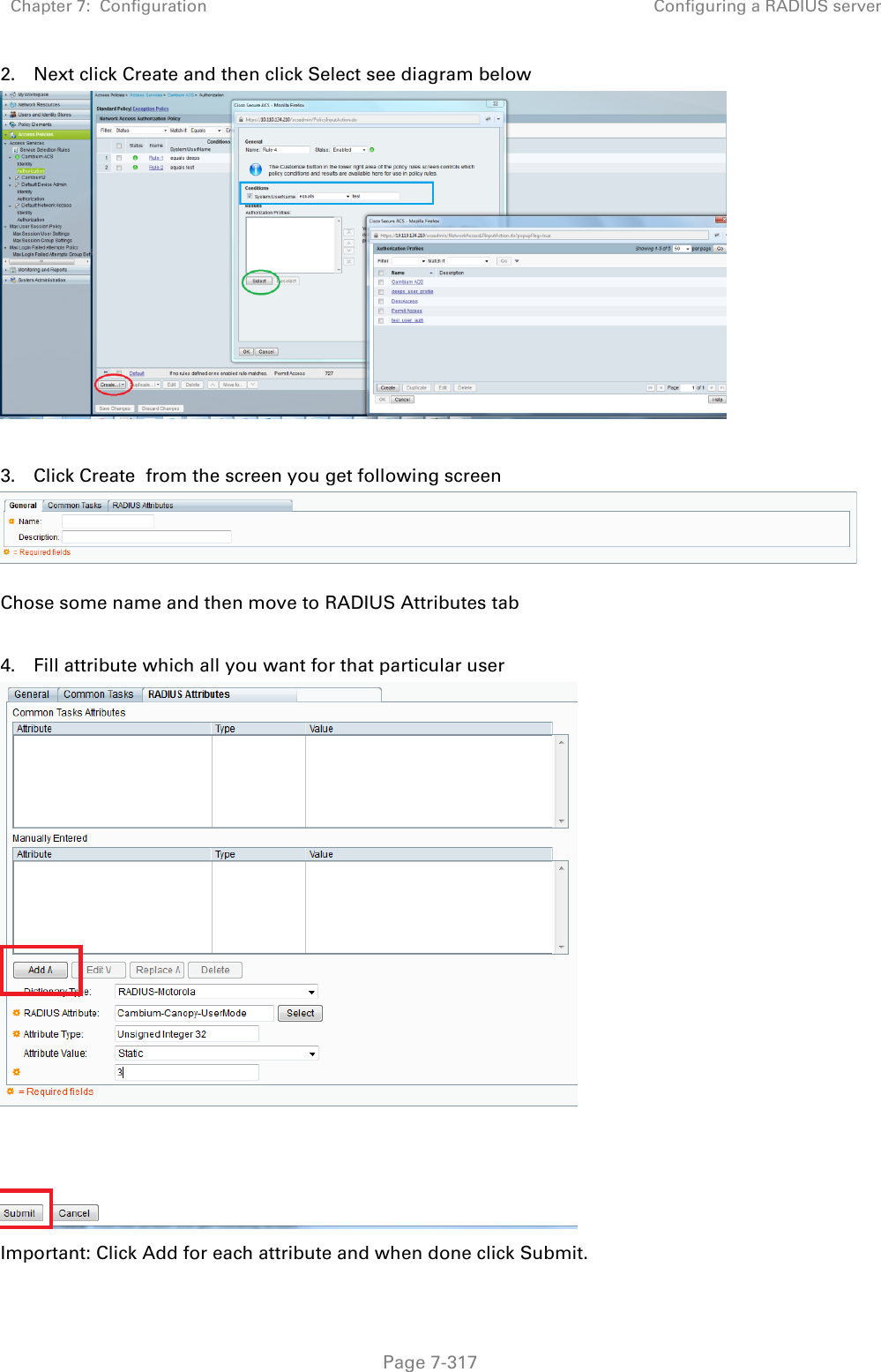
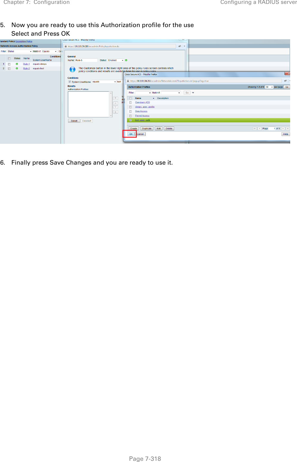
USER GUIDE P4
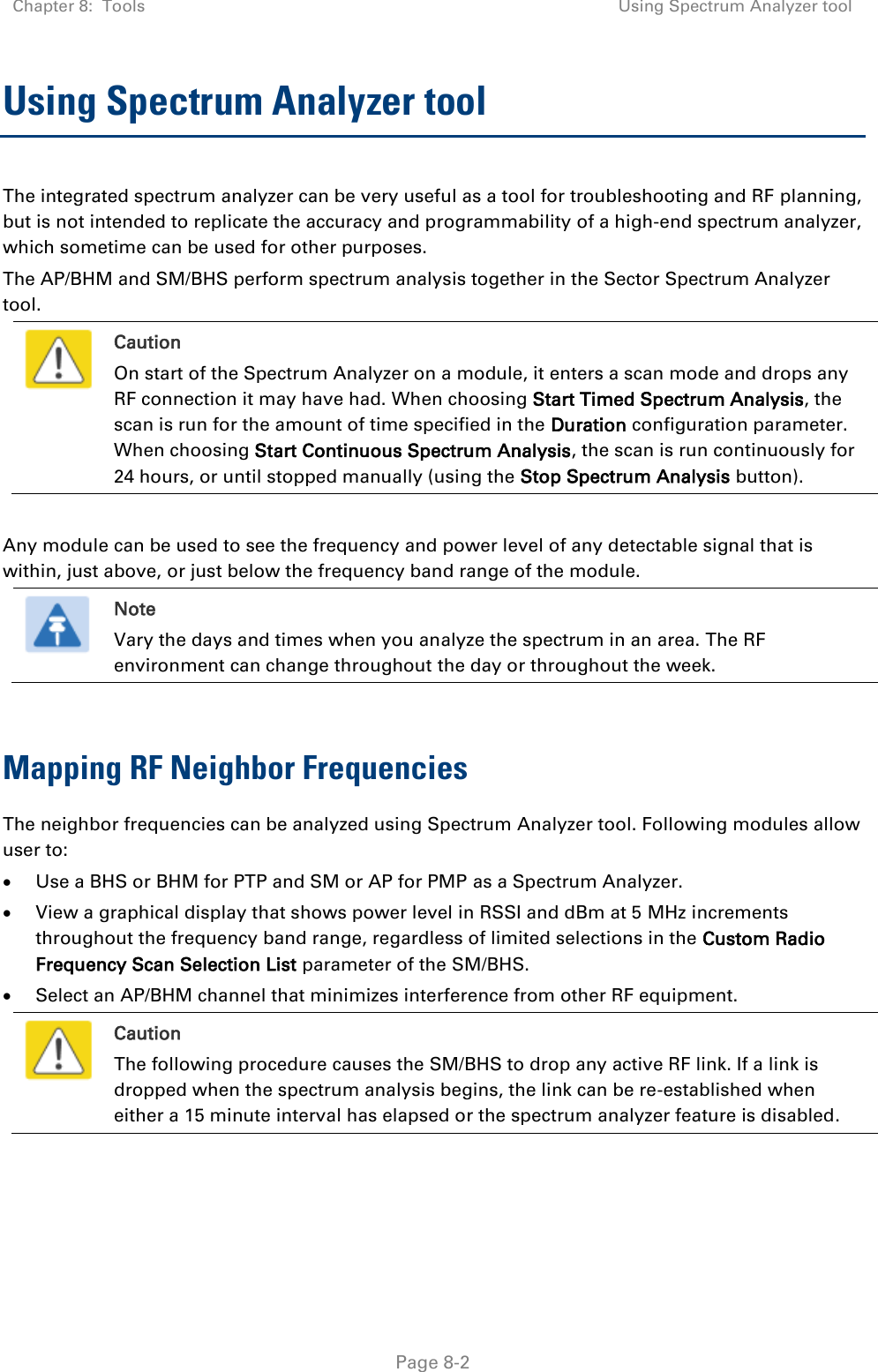
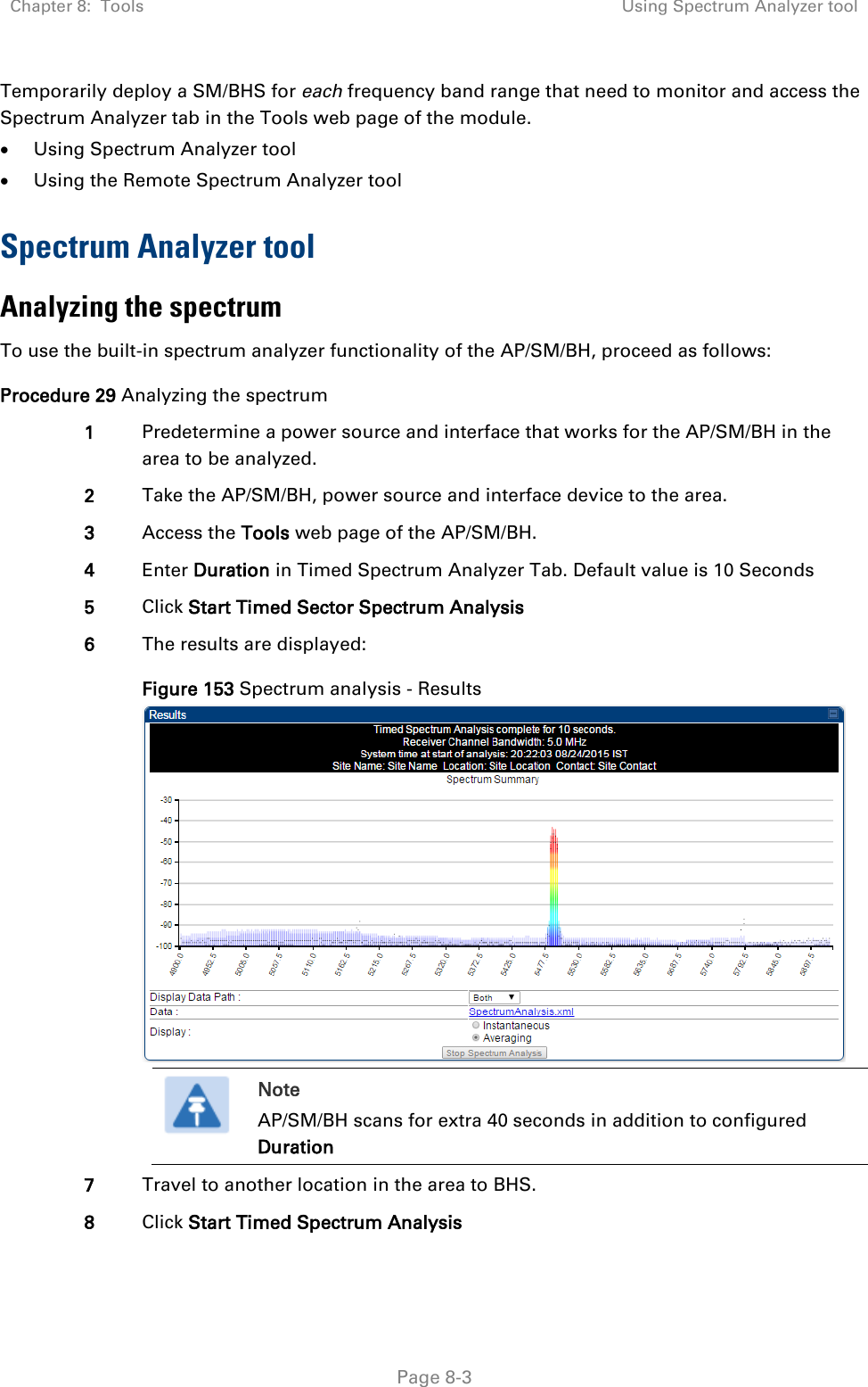
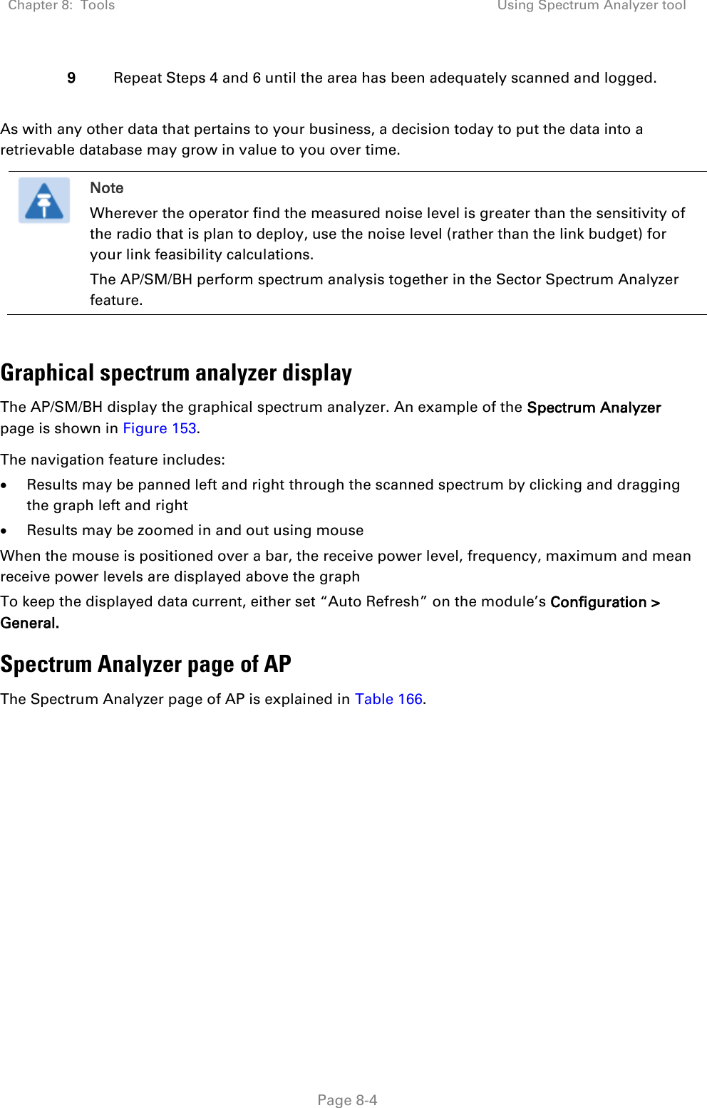
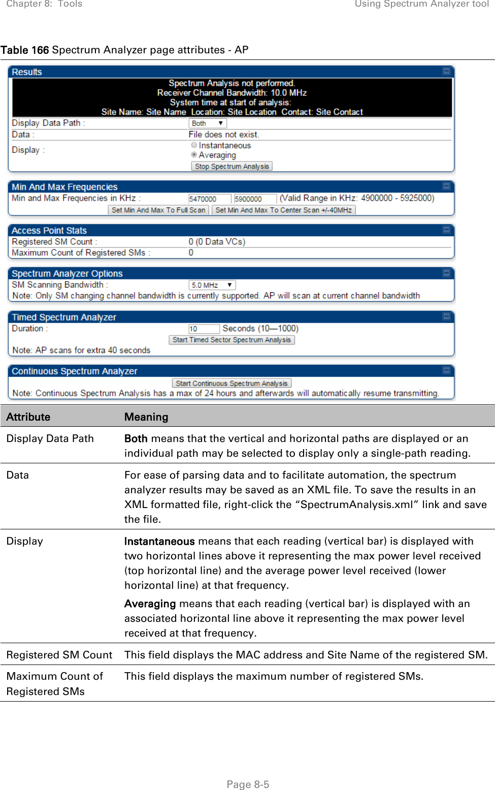
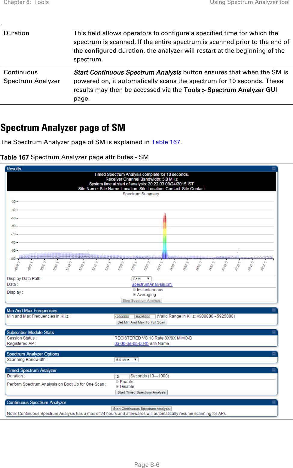
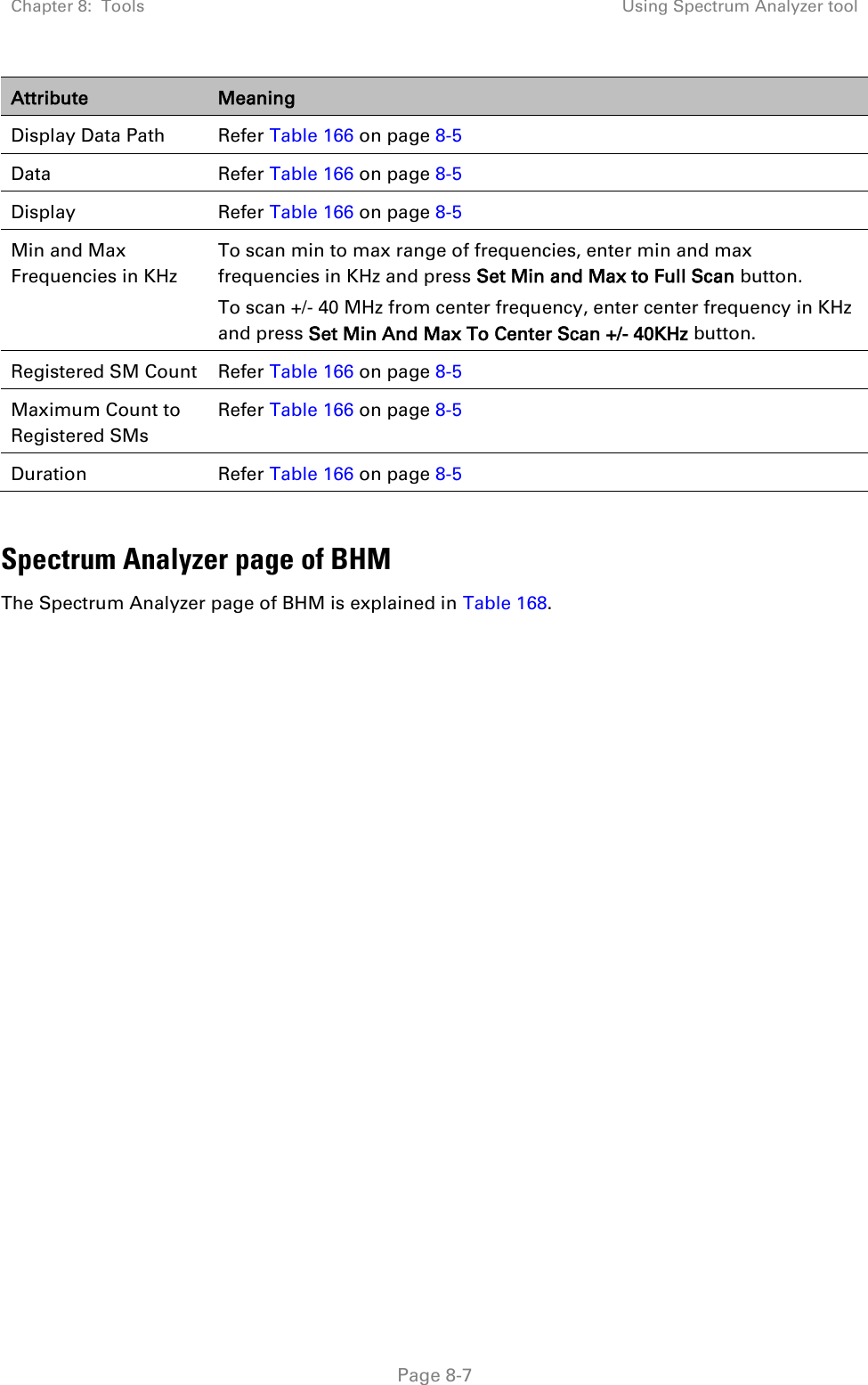
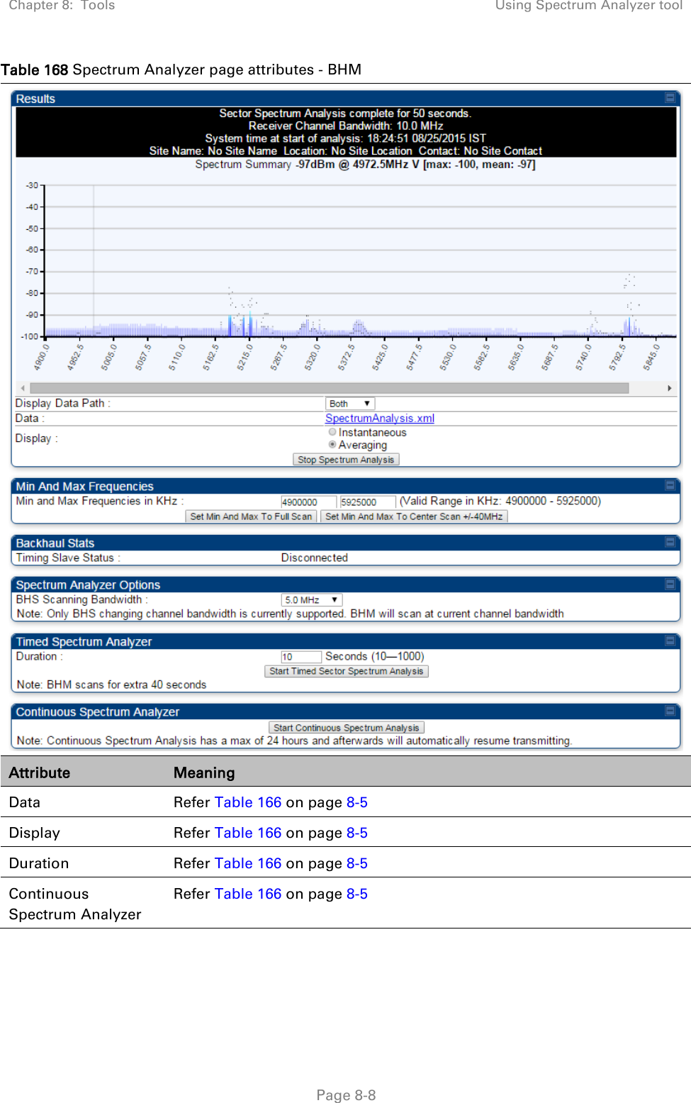
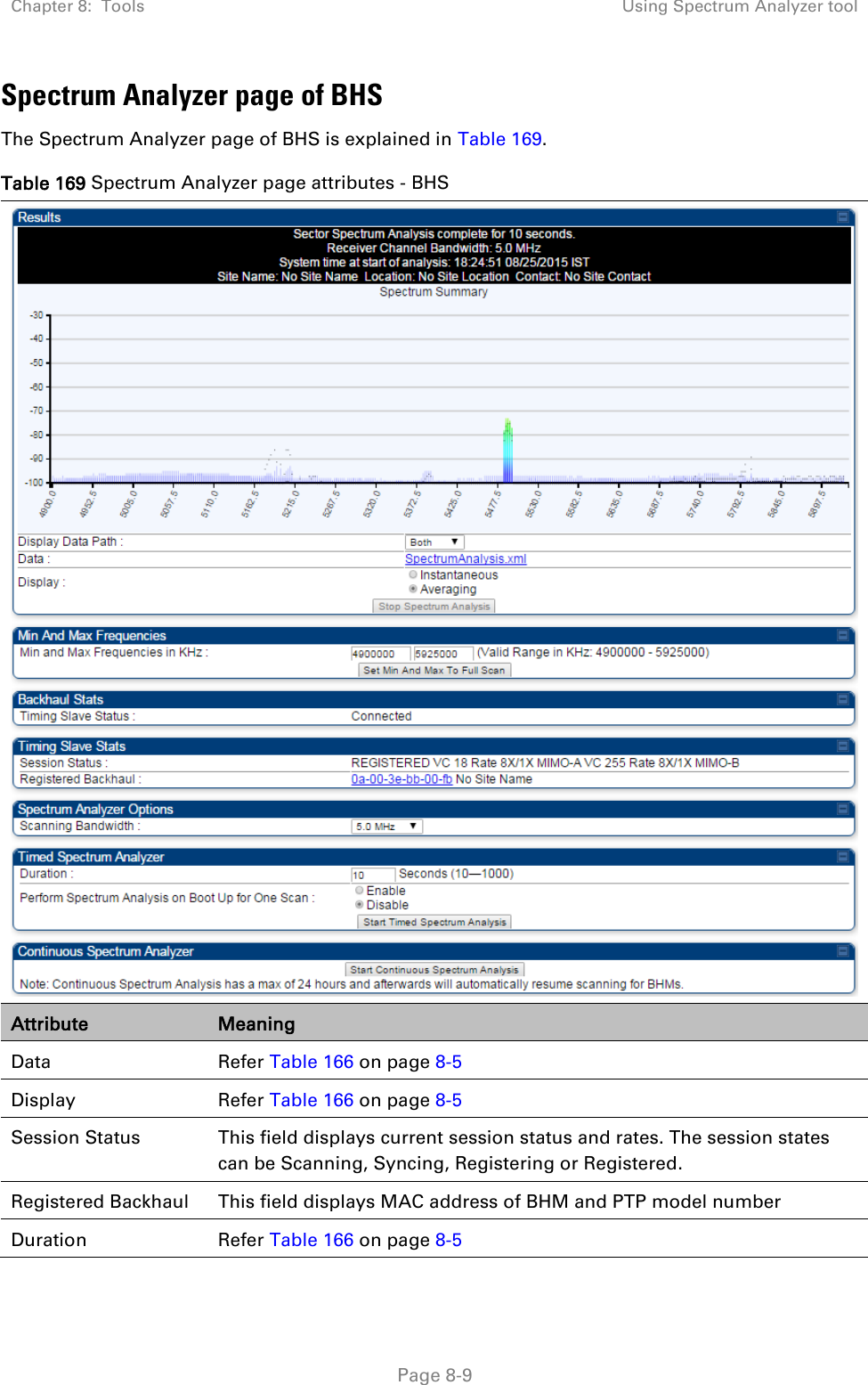
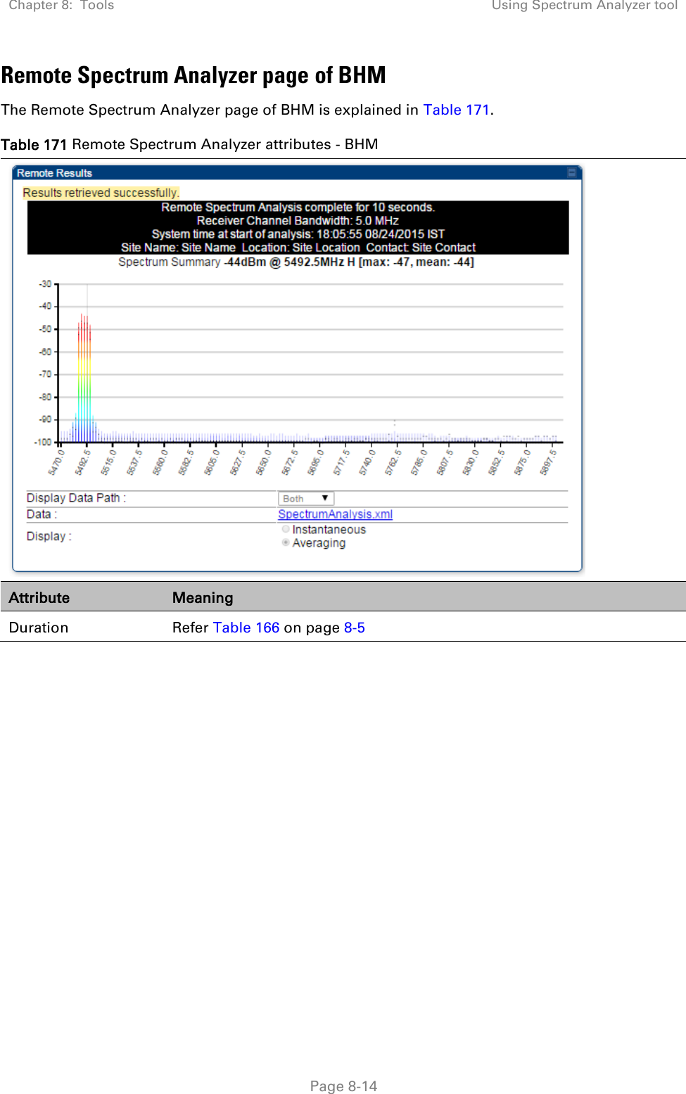
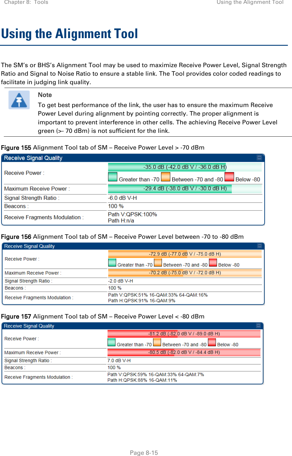
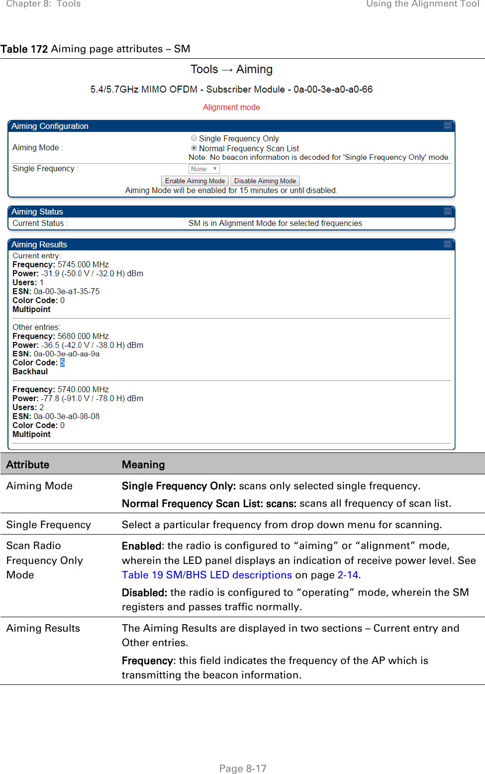
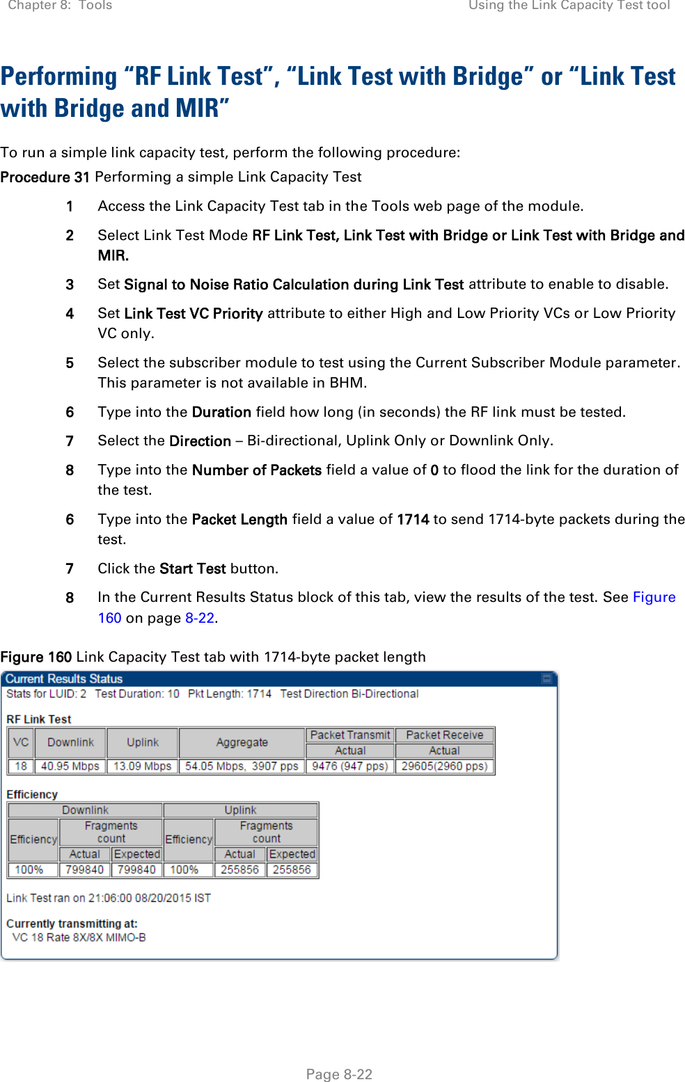
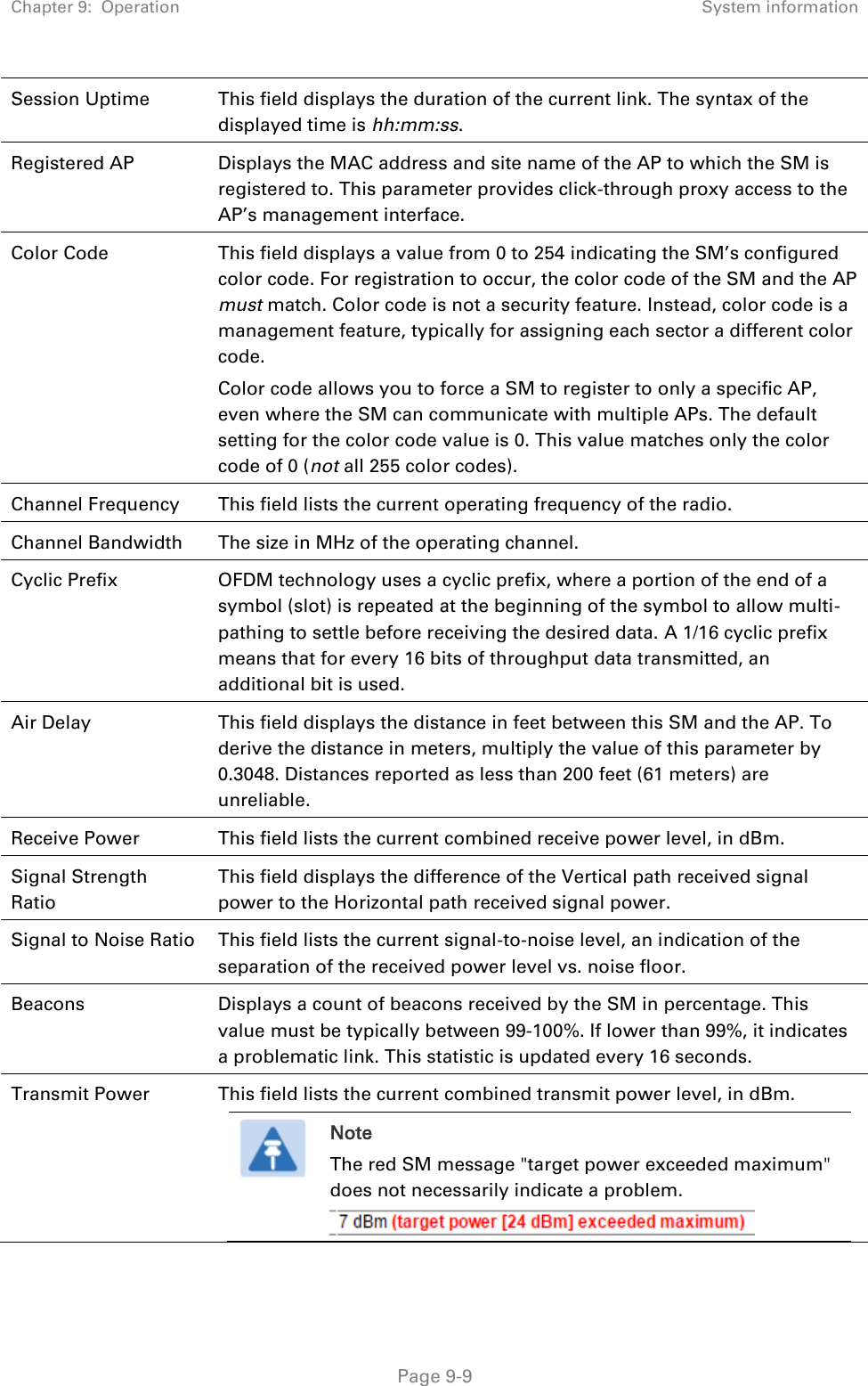
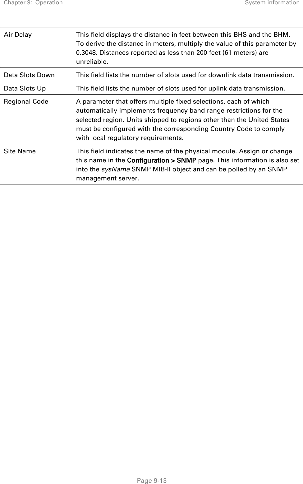
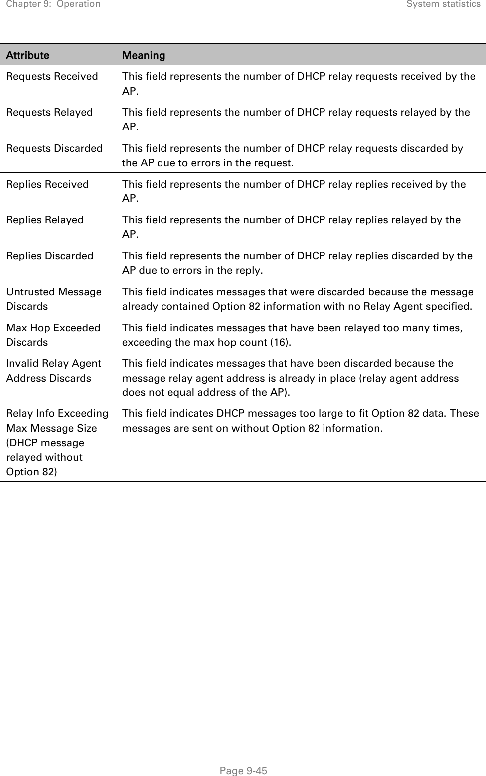
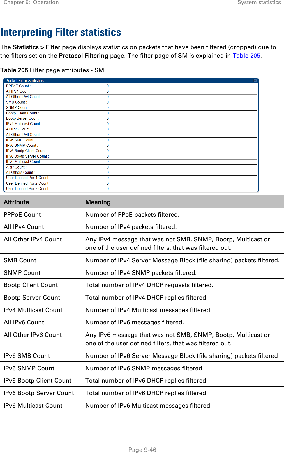
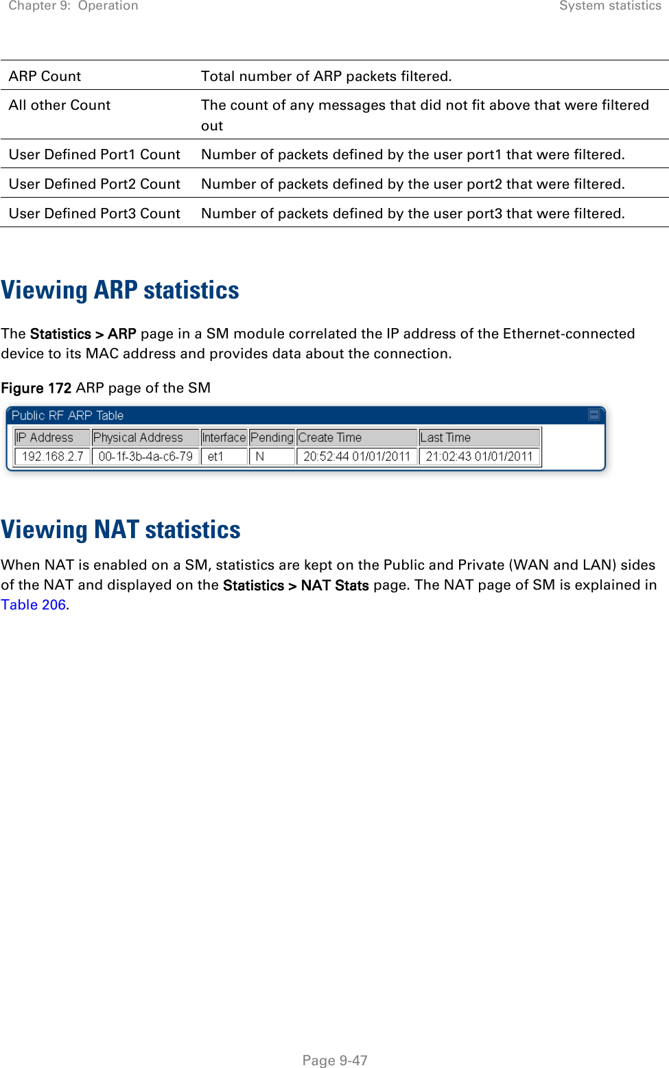
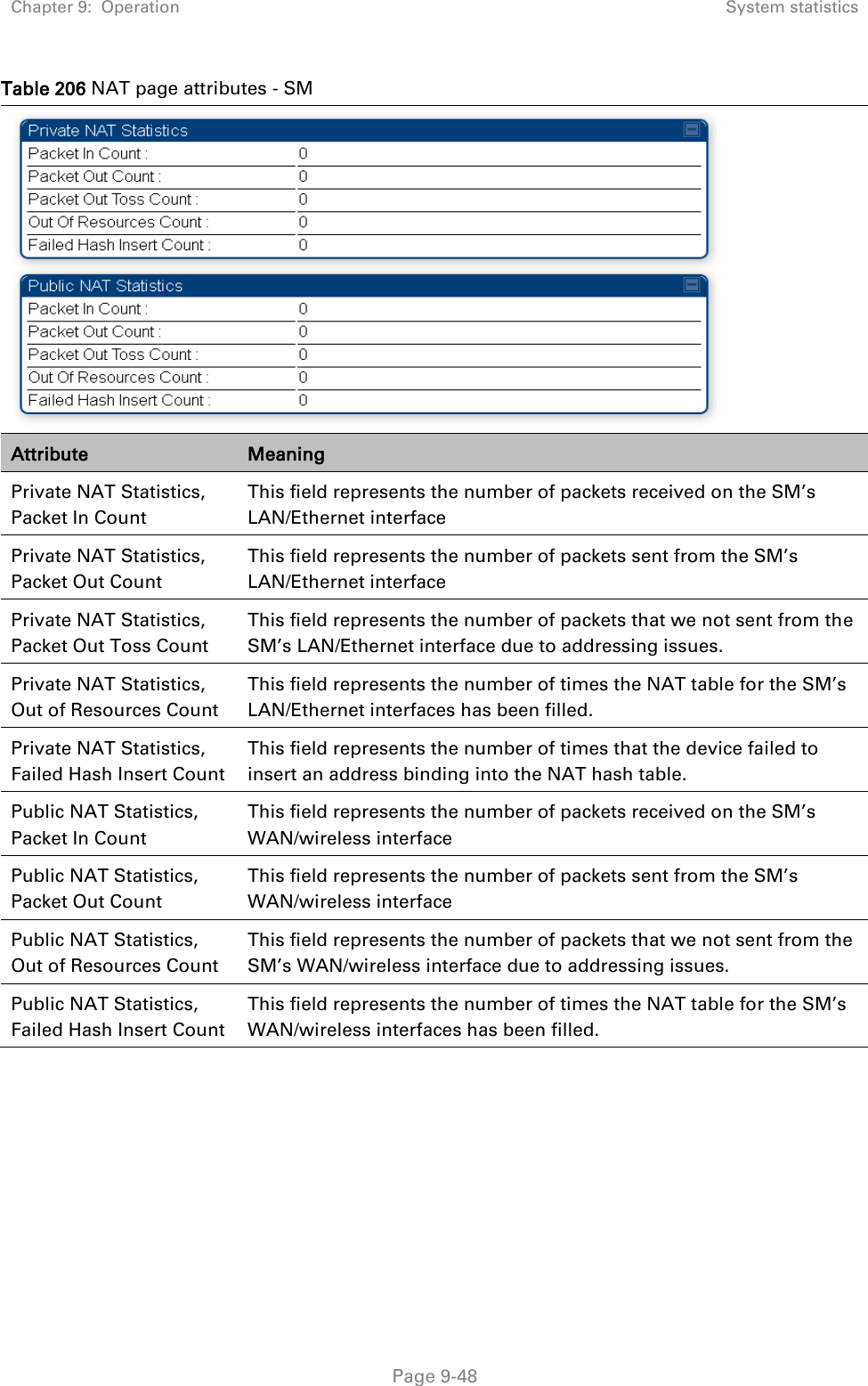
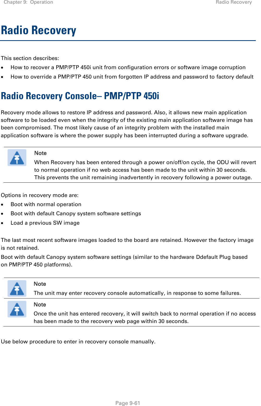
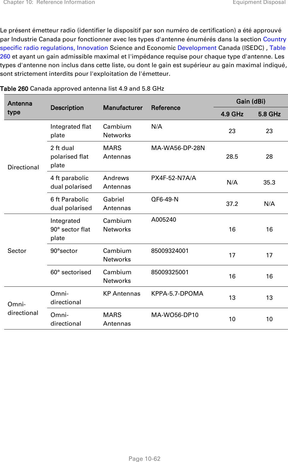
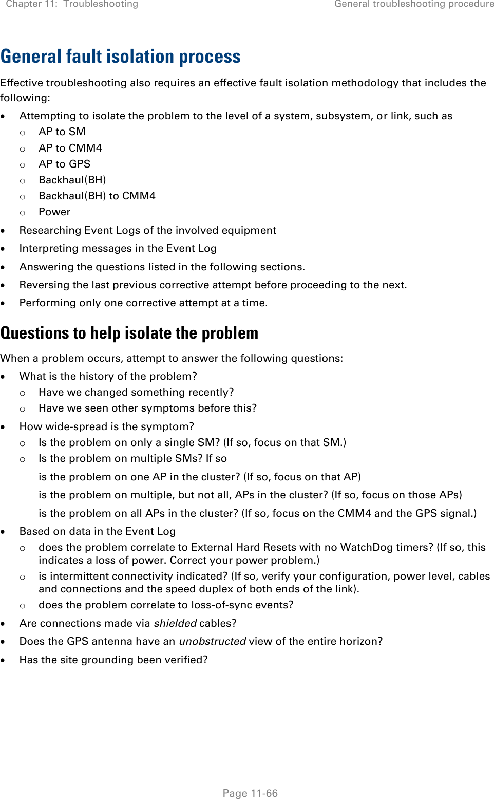
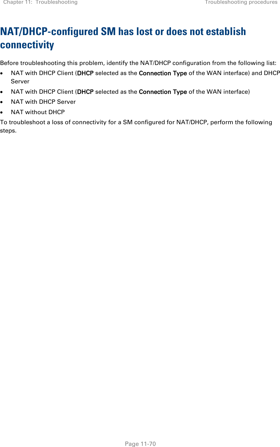
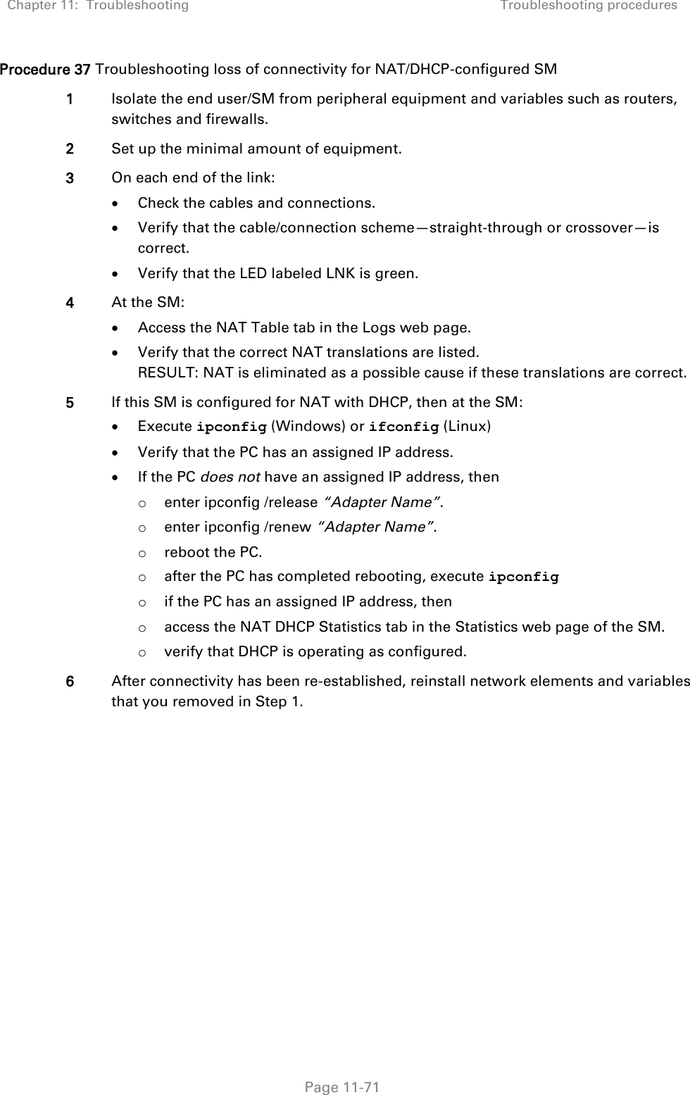
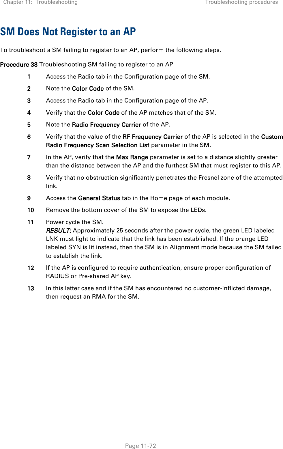
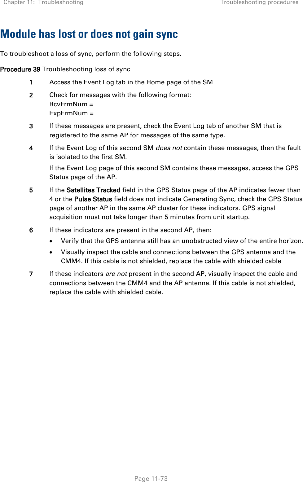
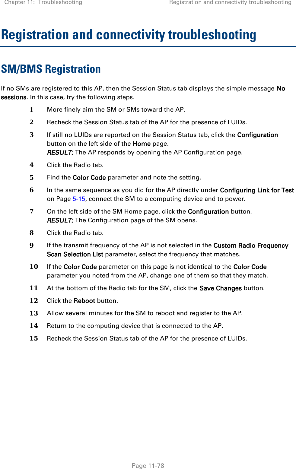
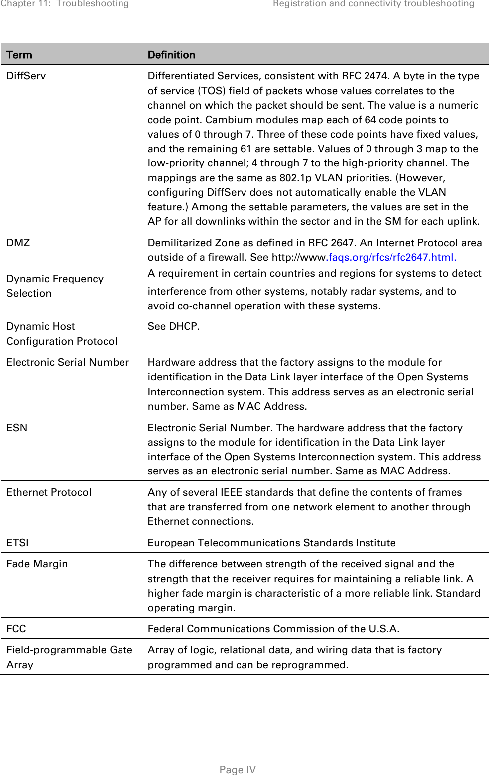
![Chapter 8: Tools Using the Link Status tool Page 8-42 BER Results This field displays the over-the-air Bit Error Rates for each downlink. (The ARQ [Automatic Resend reQuest] ensures that the transport BER [the BER seen end-to-end through a network] is essentially zero.) The level of acceptable over-the-air BER varies, based on operating requirements, but a reasonable value for a good link is a BER of 1e-4 (1 x 10⁻⁴) or better, approximately a packet resend rate of 5%. BER is generated using unused bits in the downlink. During periods of peak load, BER data is not updated as often, because the system puts priority on transport rather than on BER calculation. Reg Requests A Reg Requests count is the number of times the SM/BHS registered after the AP/BHM determined that the link had been down. If the number of sessions is significantly greater than the number for other SMs/BHS, then this may indicate a link problem (check mounting, alignment, receive power levels) or an interference problem (conduct a spectrum scan). ReReg Requests A ReReg Requests count is the number of times the AP/BHM received a SM/BHS registration request while the AP/BHM considered the link to be still up (and therefore did not expect registration requests). If the number of sessions is significantly greater than the number for other SMs/BHS, then this may indicate a link problem (check mounting, alignment, receive power levels) or an interference problem (conduct a spectrum scan). Link Status – SM/BHS The Link Status tool of SM/BHS displays Downlink Status and Uplink Status information.](https://usermanual.wiki/Cambium-Networks/50450M.USER-GUIDE-P4/User-Guide-3148372-Page-53.png)