Cisco Systems 2484-B8415-R1 WiMAX Base Station, Broadband Wireless, 2.5/2.6 GHz User Manual Installation manual Part 1
Cisco Systems, Inc WiMAX Base Station, Broadband Wireless, 2.5/2.6 GHz Installation manual Part 1
Contents
- 1. Installation manual Part 1
- 2. Installation manual Part 2
- 3. Installation manual Part 3
- 4. Installation manual Part 4
- 5. Installation manual Part 5
Installation manual Part 1

PRELIMINARY
THE SPECIFICATIONS AND INFORMATION REGARDING THE PRODUCTS IN THIS MANUAL ARE SUBJECT TO CHANGE WITHOUT NOTICE. ALL
STATEMENTS, INFORMATION, AND RECOMMENDATIONS IN THIS MANUAL ARE BELIEVED TO BE ACCURATE BUT ARE PRESENTED WITHOUT
WARRANTY OF ANY KIND, EXPRESS OR IMPLIED. USERS MUST TAKE FULL RESPONSIBILITY FOR THEIR APPLICATION OF ANY PRODUCTS.
THE SOFTWARE LICENSE AND LIMITED WARRANTY FOR THE ACCOMPANYING PRODUCT ARE SET FORTH IN THE INFORMATION PACKET THAT
SHIPPED WITH THE PRODUCT AND ARE INCORPORATED HEREIN BY THIS REFERENCE. IF YOU ARE UNABLE TO LOCATE THE SOFTWARE LICENSE
OR LIMITED WARRANTY, CONTACT YOUR CISCO REPRESENTATIVE FOR A COPY.
The following information is for FCC compliance of Class A devices: This equipment has been tested and found to comply with the limits for a Class A digital device, pursuant
to part 15 of the FCC rules. These limits are designed to provide reasonable protection against harmful interference when the equipment is operated in a commercial
environment. This equipment generates, uses, and can radiate radio-frequency energy and, if not installed and used in accordance with the instruction manual, may cause
harmful interference to radio communications.operation of this equipment in a residential area is likely to cause harmful interference, in which case users will be required to
correct the interference at their own expense.
The following information is for FCC compliance of Class B devices: The equipment described in this manual generates and may radiate radio-frequency energy. If it is not
installed in accordance with Cisco’s installation instructions, it may cause interference with radio and television reception. This equipment has been tested and found to
comply with the limits for a Class B digital device in accordance with the specifications in part 15 of the FCC rules. These specifications are designed to provide reasonable
protection against such interference in a residential installation. However, there is no guarantee that interference will not occur in a particular installation.
Modifying the equipment without Cisco’s written authorization may result in the equipment no longer complying with FCC requirements for Class A or Class B digital
devices. In that event, your right to use the equipment may be limited by FCC regulations, and you may be required to correct any interference to radio or television
communications at your own expense.
You can determine whether your equipment is causing interference by turning it off. If the interference stops, it was probably caused by the Cisco equipment or one of its
peripheral devices. If the equipment causes interference to radio or television reception, try to correct the interference by using one or more of the following measures:
• Turn the television or radio antenna until the interference stops.
• Move the equipment to one side or the other of the television or radio.
• Move the equipment farther away from the television or radio.
• Plug the equipment into an outlet that is on a different circuit from the television or radio. (That is, make certain the equipment and the television or radio are on circuits
controlled by different circuit breakers or fuses.)
Modifications to this product not authorized by Cisco Systems, Inc. could void the FCC approval and negate your authority to operate the product.
The Cisco implementation of TCP header compression is an adaptation of a program developed by the University of California, Berkeley (UCB) as part of UCB’s public
domain version of the UNIX operating system. All rights reserved. Copyright © 1981, Regents of the University of California.
NOTWITHSTANDING ANY OTHER WARRANTY HEREIN, ALL DOCUMENT FILES AND SOFTWARE OF THESE SUPPLIERS ARE PROVIDED “AS IS” WITH
ALL FAULTS. CISCO AND THE ABOVE-NAMED SUPPLIERS DISCLAIM ALL WARRANTIES, EXPRESSED OR IMPLIED, INCLUDING, WITHOUT
LIMITATION, THOSE OF MERCHANTABILITY, FITNESS FOR A PARTICULAR PURPOSE AND NONINFRINGEMENT OR ARISING FROM A COURSE OF
DEALING, USAGE, OR TRADE PRACTICE.
IN NO EVENT SHALL CISCO OR ITS SUPPLIERS BE LIABLE FOR ANY INDIRECT, SPECIAL, CONSEQUENTIAL, OR INCIDENTAL DAMAGES, INCLUDING,
WITHOUT LIMITATION, LOST PROFITS OR LOSS OR DAMAGE TO DATA ARISING OUT OF THE USE OR INABILITY TO USE THIS MANUAL, EVEN IF CISCO
OR ITS SUPPLIERS HAVE BEEN ADVISED OF THE POSSIBILITY OF SUCH DAMAGES.
CCDE, CCENT, Cisco Eos, Cisco Lumin, Cisco Nexus, Cisco StadiumVision, Cisco TelePresence, the Cisco logo, DCE, and Welcome to the Human Network are
trademarks; Changing the Way We Work, Live, Play, and Learn and Cisco Store are service marks; and Access Registrar, Aironet, AsyncOS, Bringing the Meeting To You,
Catalyst, CCDA, CCDP, CCIE, CCIP, CCNA, CCNP, CCSP, CCVP, Cisco, the Cisco Certified Internetwork Expert logo, Cisco IOS, Cisco Press, Cisco Systems,
Cisco Systems Capital, the Cisco Systems logo, Cisco Unity, Collaboration Without Limitation, EtherFast, EtherSwitch, Event Center, Fast Step, Follow Me Browsing,
FormShare, GigaDrive, HomeLink, Internet Quotient, IOS, iPhone, iQ Expertise, the iQ logo, iQ Net Readiness Scorecard, iQuick Study, IronPort, the IronPort logo,
LightStream, Linksys, MediaTone, MeetingPlace, MeetingPlace Chime Sound, MGX, Networkers, Networking Academy, Network Registrar, PCNow, PIX, PowerPanels,
ProConnect, ScriptShare, SenderBase, SMARTnet, Spectrum Expert, StackWise, The Fastest Way to Increase Your Internet Quotient, TransPath, WebEx, and the
WebEx logo are registered trademarks of Cisco Systems, Inc. and/or its affiliates in the United States and certain other countries.
All other trademarks mentioned in this document or Website are the property of their respective owners. The use of the word partner does not imply a partnership relationship
between Cisco and any other company. (0807R)
WiMAX and Mobile WiMAX are trademarks of the WiMAX Forum.
Any Internet Protocol (IP) addresses used in this document are not intended to be actual addresses. Any examples, command display output, and figures included in the
document are shown for illustrative purposes only. Any use of actual IP addresses in illustrative content is unintentional and coincidental.
BWX 8415 Basestation Installation and Commissioning Guide
© 2008 Cisco Systems, Inc. All rights reserved.

PRELIMINARY
iii
BWX 8415 Basestation Installation and Commissioning Guide
OL-19519-01
CONTENTS
About This Document ix
Purpose ix
Revision History ix
Terms ix
CHAPTER
1Safety 1-1
Warnings 1-1
Information to User 1-3
Safety Information 1-3
Safety Precautions for the BWX 8415 Basestation 1-3
CHAPTER
2Regulatory Information and Declarations of Conformity 2-1
Regulatory Information 2-1
Regulatory Requirements 2-1
Regulatory Label 2-1
Declarations of Conformity 2-3
Federal Communication Commission (FCC) Certification 2-3
Declaration of Conformity for RF Exposure 2-4
Declaration of Conformity with Regard to the 1999/5/EC (R&TTE Directive) 2-6
Declaration of Conformity Statements 2-8
2-8
CHAPTER
3Overview 3-1
3.1 Scope of this Guide 3-1
3.2 How to Use This Guide 3-1
3.3 Cisco WiMAX Documentation 3-2
3.4 BWX 8415 Basestation Components 3-4
3.5 Beamforming 3-6
CHAPTER
4Installation and Commissioning Process 4-1
4.1 The Big Picture 4-1
4.2 Planning, Preparation and Pre-Configuration 4-2
4.3 Pre-installation 4-3

PRELIMINARY
Contents
iv
BWX 8415 Basestation Installation and Commissioning Guide
OL-19519-01
4.4 Installation 4-4
4.5 Commissioning 4-5
CHAPTER
5Pre-installation 5-1
5.1 Personnel and Tools 5-1
5.2 Project Plan 5-1
5.3 RF Coverage Prediction Map 5-1
5.4 Site Candidate Evaluation 5-2
5.5 Interference Analysis 5-2
5.6 Site Design and Regulatory 5-2
5.7 Network Architecture Plan 5-2
5.8 Fiber-optic Cable Selection 5-3
5.9 Bill of Materials (BoM) 5-3
5.10 Acquire Materials, Documents and Forms 5-3
5.11 Confirm AAA, BWG, and Backhaul Network Availability 5-3
5.12 Confirm FTP and BWX EMS Server Readiness 5-4
5.13 Confirm Mounting Location and Tower Crew Availability 5-4
5.13.1 Accessibility 5-4
5.14 Confirm Power and Grounding Readiness 5-4
5.14.1 Power Requirements 5-4
5.14.2 DC Power Cable Selection 5-5
5.14.3 Grounding Requirements 5-6
5.14.4 Lightning Protection 5-6
CHAPTER
6Installation 6-1
6.1 Inventory 6-1
6.2 BWX 8415 Basestation Radio Unit (RU) Installation 6-1
6.2.1 Overview 6-1
6.2.2 BWX 8415 Basestation Radio Unit Field Testing 6-3
6.2.3 Install the Radio Unit 6-4
6.3 BWX 8415 Installation 6-6
6.3.1 Description 6-6
6.3.2 Install the GPS Antenna Cable 6-7
6.3.3 Handling the BWX 8415 Basestation 6-8
6.3.4 Mounting the BWX 8415 Basestation 6-9
6.3.5 Antenna Separation 6-12
6.3.6 Rooftop Antenna Placement Tool 6-17

PRELIMINARY
Contents
v
BWX 8415 Basestation Installation and Commissioning Guide
OL-19519-01
6.3.7 Set the Downtilt 6-18
6.3.8 Antenna Orientation 6-19
6.4 Power and Ground Cabling 6-20
6.4.1 Overview 6-20
6.4.2 System Ground Cabling 6-20
6.4.3 System Power Cabling 6-22
6.5 Fiber-Optic Cabling 6-23
6.6 Complete the BWX 8415 Installation 6-23
6.6.1 Install the I/O cable Cover 6-23
6.6.2 Test the Backhaul Connection 6-24
CHAPTER
7Commissioning 7-1
7.1 Install the Element Management System (EMS) 7-1
7.1.1 ‘Setup the ‘Test’ EMS 7-1
7.1.2 Setting Up Direct Communications Software 7-2
7.1.3 Install the BWX EMS Software and Start & Configure the BWX EMS Server 7-3
7.2 Install Access Services Network Gateway (ASN-GW) Hardware and Broadband Wireless Gateway
(BWG) Software 7-6
7.3 Add and Configure the BWG to the EMS Server 7-7
7.4 Authentication, Authorization, and Accounting (AAA) Server Installation 7-8
7.5 Add and Configure a BWX 8415 Basestation 7-9
7.5.1 Minimum System Configuration Requirements 7-9
7.5.2 Add a BWX 8415 Basestation 7-10
7.5.3 Configure a BWX 8415 Basestation 7-13
7.6 Power Up and Provision the BWX 8415 Basestation 7-28
7.6.1 Prerequisites 7-28
7.6.2 BWX 8415 Basestation Bootup 7-29
7.6.3 Provision the BWX 8415 Basestation 7-35
7.7 Calibration 7-37
7.7.1 What it Means to Calibrate 7-37
7.7.2 Types of Calibration 7-37
7.7.3 Calibration Procedure 7-38
7.8 Add, Configure, Modify and Delete Subscriber Stations (SSs) and Use Related Applications 7-44
7.8.1 Overview 7-44
7.8.2 Supported SS 7-44
7.8.3 Add, Configure, Modify and Delete an SS 7-45
7.8.4 Connection Utility 7-46
7.8.5 BWX WiMAX Diagnostic Tool Operation 7-47

PRELIMINARY
Contents
vi
BWX 8415 Basestation Installation and Commissioning Guide
OL-19519-01
7.9 Customer BWX EMS Server 7-48
7.10 Location (FTP) Test 7-51
7.10.1 Purpose 7-51
7.10.2 Setup and Procedure 7-51
7.10.3 Acceptance Criteria 7-52
7.11 Drive Study Test 7-52
7.11.1 Purpose 7-52
7.11.2 YellowFin Setup and Drive Study Test Procedure 7-53
7.11.3 BVS Chameleon Utility (YellowFin Edition) 7-61
7.11.4 Pre-process the Drive Study Data 7-63
7.12 Export BWX EMS Database 7-65
7.12.1 Create Text Files 7-65
7.13 Back Up BWX EMS Database 7-67
7.14 Photograph Installed Equipment 7-68
CHAPTER
8Closing Out the Site 8-1
8.1 Documents, Files and Forms 8-1
8.2 Photographs and Drawings 8-2
8.3 Site Closeout Checklist 8-3
APPENDIX
ACisco Recommended Tools A-1
Vendor Contact Information A-2
Agilent A-2
Berkeley Varitronics Systems, Inc. A-2
APPENDIX
BRF Coverage Prediction Map Example B-1
APPENDIX
CSite Candidate Evaluation Form C-1
APPENDIX
DRF Center Frequency and Interference Analysis Guidelines D-1
Before You Start D-1
Overview D-1
Required Equipment D-2
Spectrum Analyzer Settings D-2
Frequency Domain Test D-2
Time Domain Test D-7
Test Configurations D-9
Interference Sweep Procedure D-14

PRELIMINARY
Contents
vii
BWX 8415 Basestation Installation and Commissioning Guide
OL-19519-01
Frequency Domain (Max-hold) Test Procedure D-15
Frequency Domain Interference Sweeps Analysis D-18
Time Domain Interference Sweeps Analysis D-19
APPENDIX
EBWX 8415 Channel Filter Installation Procedure E-1
Overview (Need to Update as Required) E-1
Required Tools E-1
Channel Filter Installation Procedure E-2
APPENDIX
FRadio Unit Removal F-1
Remove the Radio Unit (RU) F-1
APPENDIX
GTranslated Safety Warnings G-1
G
LOSSARY

PRELIMINARY
Contents
viii
BWX 8415 Basestation Installation and Commissioning Guide
OL-19519-01
PRELIMINARY
ix
BWX 8415 Basestation Installation and Commissioning Guide
OL-19519-01
About This Document
Purpose
This document provides a Cisco-qualified BWX Mobile WiMAXTM Installation & Commissioning
Technician or Field Engineer with instructions to properly install a BWX 8415 Basestation (BS). The
scope includes the Radio Unit (RU), Antenna Unit (AU), power and grounding, the backhaul network,
the Access Services Network-Gateway (ASN-GW) & Broadband Wireless Gateway (BWG), and all
cabling. It also includes acceptance testing procedures.
Warning
For safety and compliance reasons, the installation and configuration described in this document
should be attempted only by persons who have completed appropriate training and achieved proper
technical certifications regarding the use and support of the applicable products. Incorrect
installation, configuration and/or service may lead to damage to the product(s) and/or risk of personal
injury, and may void your product warranty and/or entitlement to support services. You, the customer,
are responsible for obtaining and maintaining any required regulatory licenses, following
appropriate safety procedures, and providing adequately trained staff to perform any installation,
configuration and service of the products described herein.
Revision History
Terms
The information in this document pertains to the BWX Mobile WiMAX system. In this document and
all customer documents as of this release, when referring to the BWX Mobile WiMAX Basestation, the
term “BS” is used.
Date Revision/Version Contributors Editor Comments
10.30.09 -/01 PLM, Engineering J. Carrasco Release 10.0

PRELIMINARY
x
BWX 8415 Basestation Installation and Commissioning Guide
OL-19519-01
About This Document
CHAPTER
PRELIMINARY
1-1
BWX 8415 Basestation Installation and Commissioning Guide
OL-19519-01
1
Safety
Caution This document provides a Cisco-qualified BWX Mobile WiMAX Installation & Commissioning
Technician or Field Engineer with instructions to properly install a BWX 8415 Basestation (BS).
Installations performed by non-Cisco-qualified specialists will void warranties and could damage
equipment and/or cause bodily injury.
To optimize safety and expedite installation and service, read this document thoroughly. Follow all
warnings, cautions, and instructions marked on the equipment and included in this document. To aid in
the prevention of injury and damage to property, cautionary symbols have been placed in this document
to alert the reader to known potentially hazardous situations, or hazards to equipment or procedures. The
symbols are placed before the information to which they apply. However, any situation that involves
heavy equipment and electricity can become hazardous, and caution and safety should be practiced at all
times when installing, servicing, or operating the equipment.
Warnings
Translated versions of all safety warnings are available in the safety warning document that shipped with
your BS or on Cisco.com. To browse to the document on Cisco.com, refer to Appendix G, “Translated
Safety Warnings” for instructions.
Warning
IMPORTANT SAFETY INSTRUCTIONS
This warning symbol means danger. You are in a situation that could cause bodily injury. Before you
work on any equipment, be aware of the hazards involved with electrical circuitry and be familiar
with standard practices for preventing accidents. Use the statement number provided at the end of
each warning to locate its translation in the translated safety warnings that accompanied this device.
Statement 1071
SAVE THESE INSTRUCTIONS
Caution This is the symbol for “Caution - risk of equipment damage or risk of bodily injury.”
PRELIMINARY
1-2
BWX 8415 Basestation Installation and Commissioning Guide
OL-19519-01
Chapter 1 Safety
Warnings
Warning
This is the symbol for Electro-magnetic Compatibility (EMC) and Telecom non-safety related
warnings.
Warning
This equipment must be externally grounded using the supplied ground wire before power is applied.
Contact the appropriate electrical inspection authority or an electrician if you are uncertain that
suitable grounding is available.
Statement 366
Warning
Do not work on the system or connect or disconnect cables during periods of lightning activity.
Statement 1001
Warning
Read the installation instructions before connecting the system to the power source.
Statement 1004
Warning
Class 1 Laser product.
Statement 1008
Warning
Ultimate disposal of this product should be handled according to all national laws and regulations.
Statement 1040
Caution - Refer installation and service to qualified service personnel only. No user serviceable parts inside.
- Installation must be done in accordance with the instructions contained in this manual.
- Read these instructions before installing.
- Save these instructions.
Warning
- In the United states, installation must be in accordance with the National Electric Code (N.E.C.),
NFPA 70 article 810.
- In Canada, installation must be in accordance with the Canadian Electrical Code (C.E.C.), CSA C22.2,
No.1. Section 54.
- Do not mount antennas on utility poles, electric service mast, or other structures carrying electric
light or power wires. The unit and associated wiring must maintain clearance of at least 2 feet (.61
M) from power or light wires of less than 250V, or at least 10 feet (3.048 M) from power wires of more
than 250V, per N.E.C., Article 810, C.E.C. Section 54.
- Accidental contact with high voltage wires may result in death. Watch for overhead electric power
lines when erecting the unit.
- Install in accordance with all national, regional, or local electrical and building codes.
Cisco expressly requires that when using Cisco electronic equipment always follow the basic safety
precautions to reduce the risk of electrical shock, fire, and injury to people or property.
1. Follow all warnings and instructions that come with the equipment.
2. Do not disassemble the Radio Unit (RU) equipment. Removing the RU’s covers exposes dangerous
voltages or other risks and also voids the warranty. Incorrect reassembly can cause equipment
damage or electrical shock. Only an authorized repair technician should service this product.
PRELIMINARY
1-3
BWX 8415 Basestation Installation and Commissioning Guide
OL-19519-01
Chapter 1 Safety
Information to User
Warning
The BS is a Radio Frequency transmitter. It is required to comply with FCC and local country RF
exposure requirements for transmitting devices. A minimum separation distance of 2 meter or more
must be maintained between the antenna and all persons during device operations to ensure
compliance with the FCC’s and the local country’s rules for Radio Frequency Exposure. If this minimum
distance cannot be maintained, exposure to RF levels that exceed the FCC’s and the local country’s
limits may result.
Note This equipment has been tested and found to comply with the limits for a Class A digital device, pursuant
to part 15 of the FCC Rules and local country rules. These limits are designed to provide reasonable
protection against harmful interference when the equipment is operated in a commercial environment.
This equipment generates, uses, and can radiate radio frequency energy and, if not installed and used in
accordance with the instruction manual, may cause harmful interference to radio communications.
Operation of this equipment in a residential area is likely to cause harmful interference in which case the
user will be required to correct the interference at his own expense.
Information to User
The BS has been authorized as a radio frequency transmitter under the appropriate rules of the Federal
Communications Commission. Any changes or modifications not expressly approved by Cisco could
void the user’s authority to operate the equipment.
Safety Information
Follow the guidelines in this section to ensure proper operation and safe use of the access point.
Safety Precautions for the BWX 8415 Basestation
Warning
In order to comply with radio frequency (RF) exposure limits, the antennas for this product should be
positioned no less than 6.56 ft. (2 m) from your body or nearby persons.
Statement 339
Warning
Do not work on the system or connect or disconnect cables during periods of lightning activity.
Statement 1001
Warning
Class 1 laser product.
Statement 1008
Warning
A readily accessible two-poled disconnect device must be incorporated in the fixed wiring.
Statement
1022

PRELIMINARY
1-4
BWX 8415 Basestation Installation and Commissioning Guide
OL-19519-01
Chapter 1 Safety
Safety Information
Caution Only trained and qualified personnel should be allowed to install, replace, or service this equipment.
Statement 1030
Warning
Connect the unit only to DC power source that complies with the safety extra-low voltage (SELV)
requirements in IEC 60950 based safety standards.
Statement 1033
Warning
When installing or replacing the unit, the ground connection must always be made first and
disconnected last.
Statement 1046
Warning
Do not locate the antenna near overhead power lines or other electric light or power circuits, or
where it can come into contact with such circuits. When installing the antenna, take extreme care
not to come into contact with such circuits, because they may cause serious injury or death. For
proper installation and grounding of the antenna, please refer to national and local codes (for
example, U.S.:NFPA 70, National Electrical Code, Article 810, Canada: Canadian Electrical Code,
Section 54).
Statement 1052
Warning
Installation of the equipment must comply with local and national electrical codes.
Statement 1074
1. The BS must be installed in accordance with NEC/CEC Articles 800/810/830.
2. At a minimum, all DC power leads and bonding/grounding straps shall be 6 AWG or 8 AWG copper
conductors.
3. Power cables in excess of 140 feet in length must have protective devices installed that are UL listed
to UL 492, UL497A or UL497B, UL497C, and UL1449.
4. The BS must be connected to a power supply/rectifier that is IEC 60950-1 certified (UL listed to
UL60950-1 in North America) having a SELV output.
5. All power and ground conductors must be mechanically supported to avoid strain of the wires and
connection points.
6. There must not be a switch or disconnect device installed in the ground cabling.
7. A UL listed disconnect device, such as a circuit breaker, must be installed between the power supply
and BS chassis connections. The BWX 8415 BS requires a 60V, 15A, 1 sec. max break time circuit
breaker.
8. Power-interconnect wires between the power supply/rectifier and the BS unit must have heat shrink
tubing applied over the barrel of the terminal lugs after crimping the wire. A picture is provided in
the “Installation” section of this manual.
9. External power source / supply considerations for the - 40.5V DC to - 58.0V DC BS chassis:
a. An external method of disconnecting each of the DC power Load/Return lines to the BS chassis
is required (i.e. - fuse + disconnect device). The BWX 8415 BS requires a 15A circuit breaker.
b. The external power supply shall be at least 1000 Watt rating, with a maximum current > 20
amps.

PRELIMINARY
1-5
BWX 8415 Basestation Installation and Commissioning Guide
OL-19519-01
Chapter 1 Safety
Safety Information
c. The external DC power source, if current limited, shall have the limit set-point configured
higher than the BS Chassis breaker rating. (i.e. - If the power source is current limited to 10
amps and the BS circuit breaker is a 15 amp breaker, it will never trip because the power supply
is limiting the current to 10 amps.)
d. The external supply "Return" and the BS chassis shall be connected to a common Earth ground.
The BS Chassis has an external ground lug provided. The “+” terminal on the external power
supply is considered “Return or RTN” on a -48V system.
e. Do not remove protective earth connection before disconnecting the BS from the DC power
supply.

PRELIMINARY
1-6
BWX 8415 Basestation Installation and Commissioning Guide
OL-19519-01
Chapter 1 Safety
Safety Information

CHAPTER
PRELIMINARY
2-1
BWX 8415 Basestation Installation and Commissioning Guide
OL-19519-01
2
Regulatory Information and Declarations of
Conformity
Regulatory Information
Regulatory Requirements
Cisco BWX 8415 Basestations (BS) meet the following regulatory requirements:
• 2.3GHz: FCC Part 2, Part 15-B, Part 27
(2300-2400MHz) ETSI EN 302 326-2 V1.2.2, EN 301 489-4 V1.4.1, EN 503 85
RSS 195 (6.3, 6.4)
EN60950-1 & -2
UL 60950-1 & -2
CE Mark
• 2.5& 2.6GHz: FCC Part 2, Part 15-B, Part 25, Part 27
(2483.5-2690 MHz) ETSI EN 302 326-2 V1.2.2, EN 301 489-4 V1.4.1, EN 503 85
RSS 193 (6.5)
EN60950-1 & -2
UL 60950-1 & -2
CE Mark
• 3.4& 3.5GHz: ETSI EN 302 326-2 V1.2.2, EN 301 489-4 V1.4.1, EN 503 85
(3400-3525 MHz) RSS 192 (5.5, 5.6)
(3475-3600 MHz) EN60950-1 & -2
UL 60950-1 & -2
CE Mark
Regulatory Label
This is an example of the regulatory label affixed to each BS unit. It provides identification information
and appropriate regulatory approvals for that unit.
Note The professional installer may want to inspect the labels before installation, as thereafter his view of
them may be obstructed.

PRELIMINARY
2-2
BWX 8415 Basestation Installation and Commissioning Guide
OL-19519-01
Chapter 2 Regulatory Information and Declarations of Conformity
Regulatory Information
Need Example of Regulatory Label for BWX 8415

PRELIMINARY
2-3
BWX 8415 Basestation Installation and Commissioning Guide
OL-19519-01
Chapter 2 Regulatory Information and Declarations of Conformity
Declarations of Conformity
Declarations of Conformity
This section provides declarations of conformity for the BWX 8415 Basestation (BS).
This appendix contains the following sections:
• Federal Communication Commission (FCC) Certification
• Declaration of Conformity for RF Exposure
• Declaration of Conformity with Regard to the 1999/5/EC (R&TTE Directive)
• Declaration of Conformity Statements
Federal Communication Commission (FCC) Certification
Model:
WX-BS8415-23-R1
WX-BS8415-25-R1
WX-BS8415-34-R1
WX-BS8415-35-R1
FCC Certification number:
Manufacturer:
Cisco Systems, Inc.
170 West Tasman Drive
San Jose, CA 95134-1706
USA
This device complies with Part 15 rules. Operation is subject to the following two conditions:
1. This device may not cause harmful interference, and
2. This device must accept any interference received, including interference that may cause undesired
operation.
This equipment has been tested and found to comply with the limits of a Class A digital device, pursuant
to Part 15 of the FCC Rules. These limits are designed to provide reasonable protection against harmful
interference when the equipment is operated in a residential environment. This equipment generates,
uses, and radiates radio frequency energy, and if not installed and used in accordance with the
WX-BS8415-23-R1: Need FCC
Certification number
WX-BS8415-25-R1: Need FCC
Certification number

PRELIMINARY
2-4
BWX 8415 Basestation Installation and Commissioning Guide
OL-19519-01
Chapter 2 Regulatory Information and Declarations of Conformity
Declarations of Conformity
instructions, may cause harmful interference. However, there is no guarantee that interference will not
occur. If this equipment does cause interference to radio or television reception, which can be determined
by turning the equipment off and on, the user is encouraged to correct the interference by one of the
following measures:
• Reorient or relocate the receiving antenna.
• Increase separation between the equipment and receiver.
• Connect the equipment to an outlet on a circuit different from which the receiver is connected.
• Consult the dealer or an experienced radio/TV technician.
Warning
The Part 15 radio device operates on a non-interference basis with other devices operating at this
frequency when using Cisco-supplied antennas. Any changes or modification to the product not
expressly approved by Cisco could void the user’s authority to operate this device.
Warning
To meet regulatory restrictions, the BS must be professionally installed.
Declaration of Conformity for RF Exposure
This Cisco product is designed to comply with the following national and international standards on
Human Exposure to Radio Frequencies:
• US 47 Code of Federal Regulations Part 2 Subpart J
• American National Standards Institute (ANSI) / Institute of Electrical and Electronic Engineers /
IEEE C 95.1 (99)
• International Commission on Non Ionizing Radiation Protection (ICNIRP) 98
• Ministry of Health (Canada) Safety Code 6. Limits on Human Exposure to Radio Frequency Fields
in the range from 3kHz to 300 GHz
• Australia Radiation Protection Standard
• To ensure compliance with various national and international Electromagnetic Field (EM F)
standards, the system should only be operated with Cisco approved antennas and accessories.
For systems defined as Fixed Systems or systems that require professional installation for the antennas
or the antennas are roof mounted.
Note The minimum separation distance allowed is 2 meters. In these cases the distance is generally
greater than 1 meter, please verify actual MPE distance with project compliance engineer
For systems requiring On-Site evaluation See – statements for On-site evaluation
• US
This system has been evaluated for RF exposure for humans in reference to ANSI C 95.1 (American
National Standards Institute) limits. The evaluation was based on evaluation per ANI C 95.1 and
FCC OET Bulletin 65C rev 01.01.

PRELIMINARY
2-5
BWX 8415 Basestation Installation and Commissioning Guide
OL-19519-01
Chapter 2 Regulatory Information and Declarations of Conformity
Declarations of Conformity
The minimum separation distance from the antenna to general bystander is 6.56 ft. (2 meters) to
maintain compliance.
• Canada
This system has been evaluated for RF exposure for humans in reference to ANSI C 95.1 (American
National Standards Institute) limits. The evaluation was based on evaluation per RSS-102 Rev 2.
The minimum separation distance from the antenna to general bystander is 2 meters (6.56 ft.) to
maintain compliance.
• EU
This system has been evaluated for RF exposure for humans in reference to the ICNIRP
(International Commission on Non-Ionizing Radiation Protection) limits. The evaluation was based
on the EN 50385 Product Standard to Demonstrate Compliance of Radio Base stations and Fixed
Terminals for Wireless Telecommunications Systems with basic restrictions or reference levels
related to human exposure to radio frequency electromagnetic fields from 300 MHz to 40 GHz.
The minimum separation distance from the antenna to general bystander is 2 meters (6.563 ft.).
Generic Statements – for other countries
• ANSI C 95.1 (99)
This system has been evaluated for RF exposure for humans in reference to the ANSI (American
National Standards Institute) limits as referenced RF in C 95.1 (99).
The minimum separation distance from the antenna to the user is 6.56 ft. (2 meters).
• ICNIRP Limits
This system has been evaluated for RF exposure for humans in reference to the ICNIRP
(International Commission on Non-Ionizing Radiation Protection) limits.
The minimum separation distance from the antenna to the user is 2 meters (6.56 ft.).
PRELIMINARY
2-6
BWX 8415 Basestation Installation and Commissioning Guide
OL-19519-01
Chapter 2 Regulatory Information and Declarations of Conformity
Declarations of Conformity
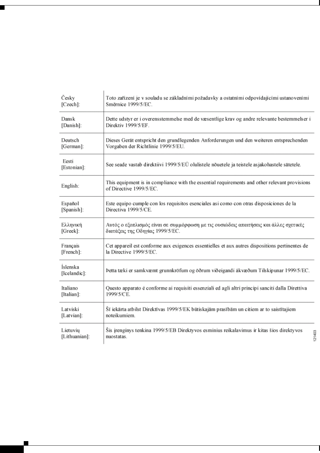
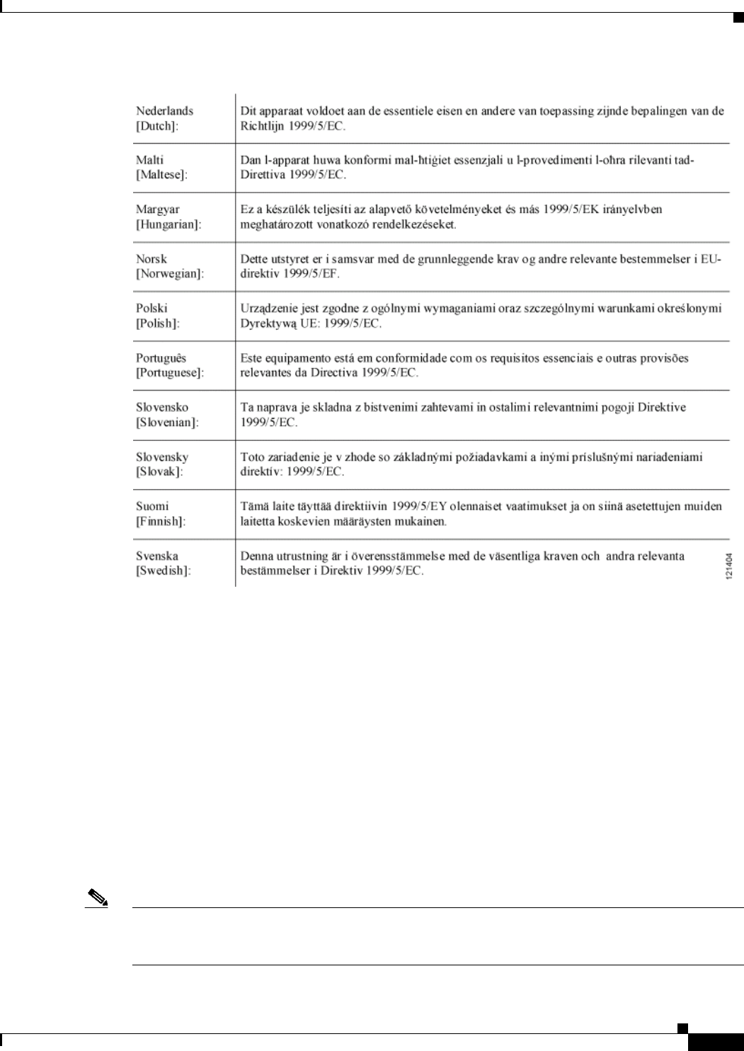
Declaration of Conformity with Regard to the 1999/5/EC (R&TTE Directive)
This declaration is only valid for configurations (combinations of software, firmware, and hardware)
provided and supported by Cisco Systems. The use of software or firmware not provided and supported
by Cisco Systems may result in the equipment no longer being compliant with the regulatory
requirements.
PRELIMINARY
2-7
BWX 8415 Basestation Installation and Commissioning Guide
OL-19519-01
Chapter 2 Regulatory Information and Declarations of Conformity
Declarations of Conformity
For 2.3 GHz, the following standards were applied:
• Radio: EN 302 326-2 V1.2.2
• EMC: EN 301 489-4 V1.4.1
• Safety: EN 60950-1, EN 60950-2
For 2.5-2.6 GHz, the following standards were applied:
• Radio: EN 302 326-2 V1.2.2
• EMC: EN 301 489-4 V1.4.1
• Safety: EN 60950-1, EN 60950-2
For 3.4-3.5 GHz, the following standards were applied:
• Radio: EN 302 326-2 V1.2.2,
• EMC: EN 301 489-4 V1.4.1
• Safety: EN 60950-1, EN 60950-2
Note This equipment is intended to be used in all EU and EFTA countries. Outdoor use may be restricted to
certain frequencies and/or may require a license for operation. For more details, contact Cisco Corporate
Compliance.

PRELIMINARY
2-8
BWX 8415 Basestation Installation and Commissioning Guide
OL-19519-01
Chapter 2 Regulatory Information and Declarations of Conformity
Declarations of Conformity
The following CE mark is affixed to the basestation, user’s manual, and packaging:
Declaration of Conformity Statements
All the Declaration of Conformity statements related to this product can be found at the following URL:
http://www.ciscofax.com
15881588

CHAPTER
PRELIMINARY
3-1
BWX 8415 Basestation Installation and Commissioning Guide
OL-19519-01
3
Overview
3.1 Scope of this Guide
This document was created specifically for the BWX 8415 Basestation (BS), which allows service
providers to service users with Mobile WiMAX technology.
WiMAX is a standards-based, Orthogonal Frequency Division Multiplexing Access (OFDMA)
technology. The procedures in this document are non-frequency specific. This guide serves as the
instructions for all BWX 8415 BS installations.
3.2 How to Use This Guide
Properly installing and commissioning a BS into commercial operation begins with planning. Cisco
advises skills-certified Installation & Commissioning Technicians to review this entire document and its
referenced material at the beginning of a successful deployment.
Cisco is serious about ensuring your success. In fact, Cisco does not warranty its hardware if the BS has
not been deployed by a Cisco skills-certified Installation & Commissioning Technician. To install and
commission a BS, you will need a standard toolkit, as well as Cisco-specific tools, software,
documentation, and forms that are explained in this guide.
Some procedures described in this guide are optional because they depend upon a particular
configuration or service provider preference. If you are not certain whether or not you should perform
an optional task, please feel free to contact your account representative or Cisco Technical Assistance
Center (TAC) for assistance. Unless specified as optional, assume the procedure or task must be
completed.

PRELIMINARY
3-2
BWX 8415 Basestation Installation and Commissioning Guide
OL-19519-01
Chapter 3 Overview
3.3 Cisco WiMAX Documentation
3.3 Cisco WiMAX Documentation
Table 3-1 is a complete list of all documents and forms referenced in this guide. Cisco WiMAX
documents are maintained on a LiveLink web page. When you completed your skills
certification/qualification, you should have received your login instructions. If not, please contact the
Cisco BWBU WiMAX Documentation team by emailing bwbu-docs@cisco.com. Refer to the following
link for access to the appropriate LiveLink web page:
BWBU_Documentation:
https://tools.cisco.com/cws/livelink?func=ll&objid=4353291&objaction=browse
Note that for some components in the WiMAX Profile C configuration, this guide refers to other Cisco
documentation [for example, the Access Services Network Gateway (ASN-GW)]. When those
components are referenced, a link to the www.cisco.com site is provided.
Please make sure you have access to all necessary documentation prior to beginning the installation.
Some documents and forms are software- or hardware-level sensitive. Always ensure you have the
correct version of documents related to the system you are installing.
Ta b l e 3-1 Cisco WiMAX Documentation
Title of Document or Form Where to Find It Cisco Part Number
Release Notes for BWX Mobile WiMAX
Release 10.0
LiveLink Site:
BWBU_Documentation>Standard
By Request Only Documents>10.0
Standard by Request Documents
OL-19152-01
BWX Mobile WiMAX Cell Site Planning
Guide
LiveLink Site:
BWBU_Documentation>Standard
By Request Only Documents>10.0
Standard by Request Documents
OL-16328-04
BWBU WiMAX Documentation Roadmap LiveLink Site:
BWBU_Documentation>
STANDARD_DOCS>10.0
Standard Documents
OL-18211-03
BWX Mobile WiMAX RF Planning Guide LiveLink Site:
BWBU_Documentation>Standard
By Request Only Documents>10.0
Standard by Request Documents
OL-16333-04
BWX Mobile WiMAX Migration Planning
Guide
LiveLink Site:
BWBU_Documentation>Standard
By Request Only Documents>10.0
Standard by Request Documents
OL-16311-04
BWX Mobile WiMAX Overview Manual LiveLink Site:
BWBU_Documentation>
STANDARD_DOCS>10.0
Standard Documents
OL-16317-04

PRELIMINARY
3-3
BWX 8415 Basestation Installation and Commissioning Guide
OL-19519-01
Chapter 3 Overview
3.3 Cisco WiMAX Documentation
BWX Mobile WiMAX Configuration Guide LiveLink Site:
BWBU_Documentation>Standard
By Request Only Documents>10.0
Standard by Request Documents
OL-16313-04
Configuring WiMAX Subscriber Stations
Using Cisco Access Registrar (CAR)
LiveLink Site:
BWBU_Documentation>Standard
By Request Only Documents>10.0
Standard by Request Documents
OL-17837-03
BWX EMS Software Installation Guide LiveLink Site:
BWBU_Documentation>Standard
By Request Only Documents>10.0
Standard by Request Documents
OL-16309-04
BWX EMS Config CLI Reference Manual LiveLink Site:
BWBU_Documentation>Standard
By Request Only Documents>10.0
Standard by Request Documents
OL-16306-04
BWX EMS Overview Manual LiveLink Site:
BWBU_Documentation>
STANDARD_DOCS>10.0
Standard Documents
OL-16308-04
BWX EMS Alarm Resolution Reference
Manual
LiveLink Site:
BWBU_Documentation>Standard
By Request Only Documents>10.0
Standard by Request Documents
OL-16305-04
BWX EMS Diagnostic Tools Guide LiveLink Site:
BWBU_Documentation>Standard
By Request Only Documents>10.0
Standard by Request Documents
OL-16307-04
BWX 350 USB Modem User Guide LiveLink Site:
BWBU_Documentation>
STANDARD_DOCS>10.0
Standard Documents
OL-19151-02
BWX Modem Diagnostics Tool User Guide LiveLink Site:
BWBU_Documentation>TIER 1
& 2 Technical Support Docs>10.0
Tier 1 & 2 Technical Support Docs
OL-17840-04
Cisco Recommended Tools Appendix A, “Cisco
Recommended Tools”
OL-16336-04
RF Coverage Prediction Map Appendix B, “RF Coverage
Prediction Map Example”
OL-16336-04
Table 3-1 Cisco WiMAX Documentation
Title of Document or Form Where to Find It Cisco Part Number

PRELIMINARY
3-4
BWX 8415 Basestation Installation and Commissioning Guide
OL-19519-01
Chapter 3 Overview
3.4 BWX 8415 Basestation Components
3.4 BWX 8415 Basestation Components
A Cisco BWX Mobile WiMAX system provides wireless broadband access to a core network, typically to the
Internet or to any local or wide area network (LAN/WAN). When a service provider has established BS’s in
a given coverage area, the subscriber connects a BWX 350 USB Modem or other WiMAX-certified device to
their computer to access the network without the need for a professional installer.
This is what Cisco refers to when it says its system is “zero-install®”: no truck rolls, no professional
installation schedule for the consumer. In fact, some service providers have their subscribers pick up
their modems at retail stores, or, in some cases, simply mail the modems to the subscribers. The
subscriber modem is generally referred to as Subscriber Station (SS). The SS can be a BWX 350 USB
Modem, which inserts into the USB slot of a laptop computer, or another WiMAX-certified device.
In Release 10.0 Cisco offers three subscriber stations (SS): the BWX 320 IDU modem, the BWX 350
USB modem, and the BWX 360 Outdoor modem. The BWX 320 IDU modem connects to PCs, utilizing
the ethernet connection of the PC and covers a 5 MHz frequency range, the BWX 350 USB modem plugs
into laptops, utilizing the USB port of the PC and covers a 5 MHz frequency range, and the BWX 360
Outdoor modem connects to PCs, utilizing the ethernet connection of the PC and covers a 5 or 10 MHz
frequency range.
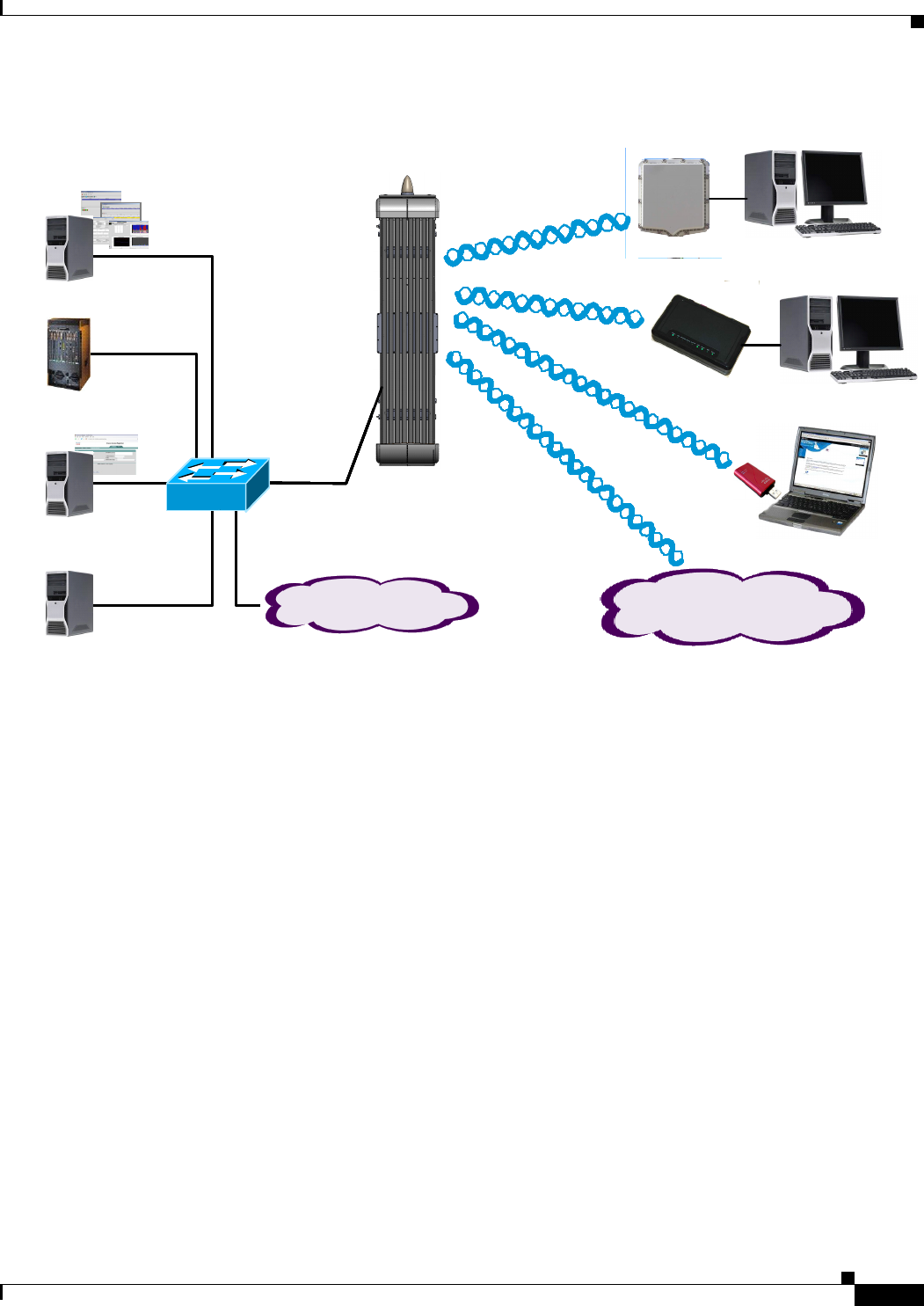
The entire BWX Mobile WiMAX system (Figure 3-1) has six main components: one or more
basestations, Subscriber Stations (SSs, also referred to as modems), the Element Management System
(EMS), the Broadband Wireless Gateway (BWG), the Authentication, Authorization, and Accounting
(AAA) server, and the Dynamic Host Configuration Protocol/Domain Name Server (DHCP/DNS)
server. The BS portion of the system consists of the Radio Unit (RU) and the Antenna Unit (AU).
Site Candidate Evaluation Form LiveLink Site:
BWBU_Documentation>TIER 1
Installation & Commissioning
Docs>10.0 Tier 1 Installation &
Commissioning Docs
Copy of front sheet shown in
Appendix C, “Site Candidate
Evaluation Form”
OL-16336-04
RF Center Frequency & Interference
Analysis Guidelines
Appendix D, “RF Center
Frequency and Interference
Analysis Guidelines”
OL-16336-04
Channel Filter Installation Procedure Appendix E, “BWX 8415 Channel
Filter Installation Procedure”
OL-16336-04
Table 3-1 Cisco WiMAX Documentation
Title of Document or Form Where to Find It Cisco Part Number
PRELIMINARY
3-5
BWX 8415 Basestation Installation and Commissioning Guide
OL-19519-01
Chapter 3 Overview
3.4 BWX 8415 Basestation Components
Figure 3-1 BWX Mobile WiMAX System Components
The BS performs the conversion of RF signals to digital signals for packets transmitted uplink (SS to BS),
and converts digital signals to RF signals for packets transmitted downlink (BS to SS). The BS interfaces with
the BWG and either directs traffic to/from the BWG (residential service) or tags the traffic to route to/from a
private network (Business/Enterprise service).
The BS uses a Global Positioning System (GPS) antenna connected to the built-in GPS circuit.
Warranty and ongoing TAC support on the BS only covers BSs deployed with the supported
configuration.
The EMS is a set of software applications that the service provider uses to configure, communicate with,
and manage all the system elements directly related to the Broadband Wireless Access system. EMS
provides a single point for managing BWG-to-BS, BWG-to-EMS, BS, and SS communications in a
WiMAX network.
The EMS is an IP-based element manager designed in a server-client relationship and runs on either Windows
or Solaris Operating Systems. Most service providers use the Client EMS Configuration & Alarm Manager
(CAM) application to interface with the system. All of the functions that can be performed through the CAM
can also be performed through a Command Line Interface (CLI), which is a common computing language
across platforms. In addition, the CLI can run scripts consisting of a text file with CLI commands. This
functionality is not available in the CAM.
BWX 8415
Basestation
GPS
Antenna
BWG
EMS
AAA
DHCP
DNS Backhaul Network
BS
SS
Other WiMAX
Ce rtifie d De vice s
BWX 8415
Basestation
GPS
Antenna
BWG
EMS
AAA
DHCP
DNS Backhaul Network
BS
SS
Other WiMAX
Ce rtifie d De vice s
BWX 8415
Basestation
GPS
Antenna
BWG
EMS
AAA
DHCP
DNS Backhaul NetworkBackhaul Network
BS
SS
BWX 350
USB Modem
Other WiMAX
Ce rtifie d De vice s
Other WiMAX
Ce rtifie d De vice s
BWX 320
IDU Modem
BWX 360
Outdoor Modem
BWX 8415
Basestation
GPS
Antenna
BWG
EMS
AAA
DHCP
DNS Backhaul Network
BS
SS
Other WiMAX
Ce rtifie d De vice s
BWX 8415
Basestation
GPS
Antenna
BWG
EMS
AAA
DHCP
DNS Backhaul Network
BS
SS
Other WiMAX
Ce rtifie d De vice s
BWX 8415
Basestation
GPS
Antenna
BWG
EMS
AAA
DHCP
DNS Backhaul NetworkBackhaul Network
BS
SS
BWX 350
USB Modem
Other WiMAX
Ce rtifie d De vice s
Other WiMAX
Ce rtifie d De vice s
BWX 320
IDU Modem
BWX 360
Outdoor Modem
PRELIMINARY
3-6
BWX 8415 Basestation Installation and Commissioning Guide
OL-19519-01
Chapter 3 Overview
3.5 Beamforming
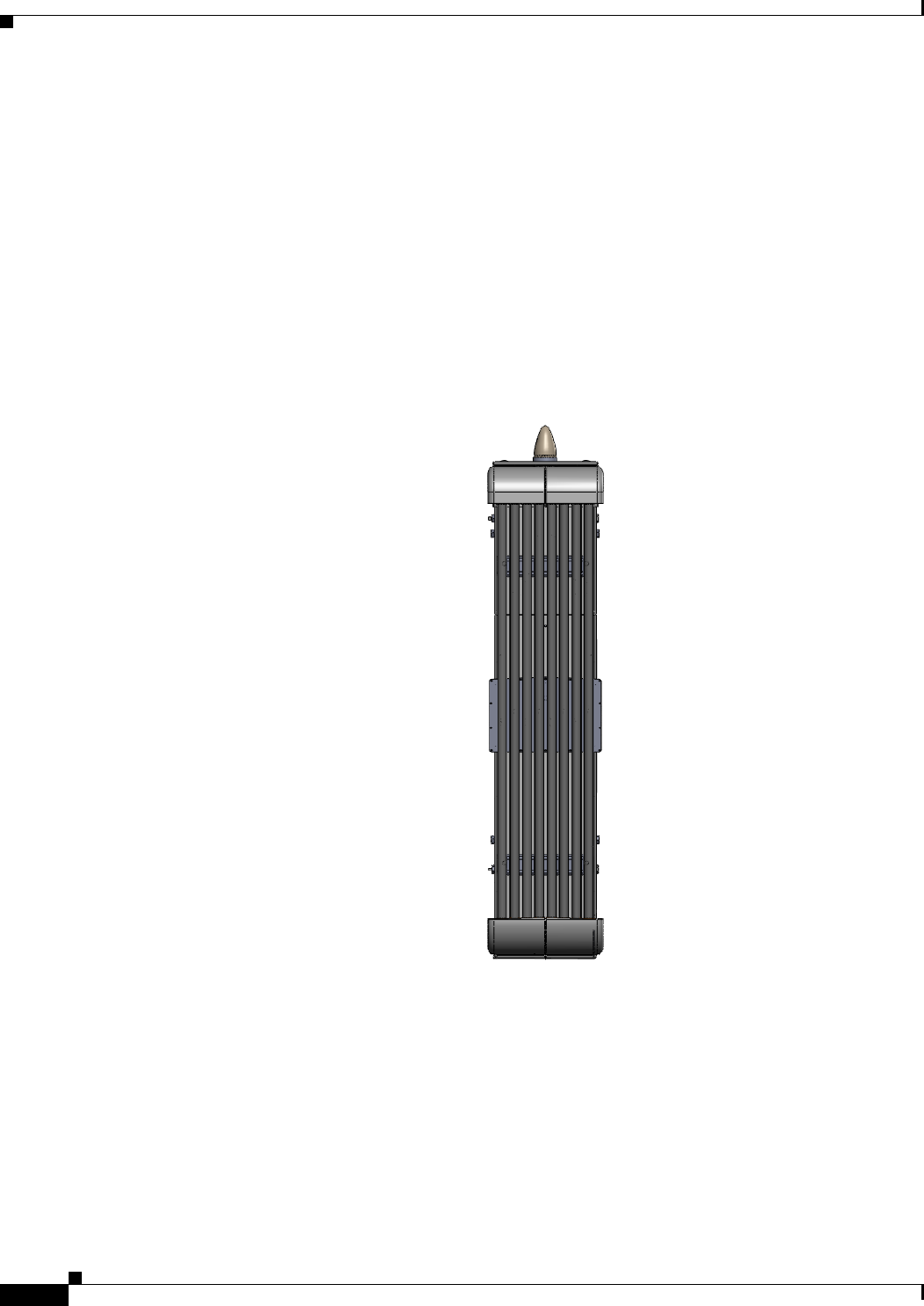
3.5 Beamforming
Cisco BWX 8415 Basestation antennas contain eight elements (Figure 3-2), with a gain of 16 dBi. Their
combined effect is to concentrate the downlink data into a beam with maximum gain at the location of
each target SS (Figure 3-3).
Similarly, in the uplink the data transmitted by each SS is received by the eight antenna elements with
different phases due to the differences in propagation distance from an SS to each antenna element. The
contributions from an SS are added up coherently after adjusting their phases for maximum gain. This
effect, which we call beamforming, is equivalent to having up to 18 dB of additional gain in the downlink
and up to 9 dB additional gain in the uplink. It allows the Cisco BWX Mobile WiMAX system to operate
at a much lower power level than would otherwise be necessary for the same results.
Figure 3-2 BWX 8415 Basestation
PRELIMINARY
3-7
BWX 8415 Basestation Installation and Commissioning Guide
OL-19519-01
Chapter 3 Overview
3.5 Beamforming
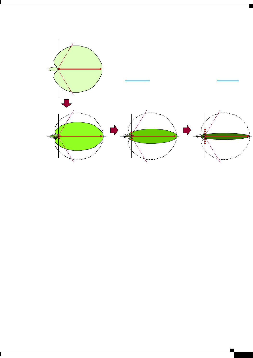
Figure 3-3 Beamforming
The phase of the individual elements is
controlled so that their contributions to the
EM field add up constructively (thus
concentrating the power of the beam) in a
particular direction
Doubling the number of elements doubles
the concentration of the beam
Our antennas have 2 × 2 × 2 = 8 elements
3 + 3 + 3 = 9 dB of gain
Concentrate the beam × 2
Concentrate the beam × 2 Concent rate the beam × 2
Concentrate the beam × 2Concentrate the beam × 2
Concentrate the beam × 2 Concent rate the beam × 2Concentrate the beam × 2 Concent rate the beam × 2

PRELIMINARY
3-8
BWX 8415 Basestation Installation and Commissioning Guide
OL-19519-01
Chapter 3 Overview
3.5 Beamforming