Cisco Systems 2484-B8415-R1 WiMAX Base Station, Broadband Wireless, 2.5/2.6 GHz User Manual Installation manual Part 1
Cisco Systems, Inc WiMAX Base Station, Broadband Wireless, 2.5/2.6 GHz Installation manual Part 1
Contents
- 1. Installation manual Part 1
- 2. Installation manual Part 2
- 3. Installation manual Part 3
- 4. Installation manual Part 4
- 5. Installation manual Part 5
Installation manual Part 1
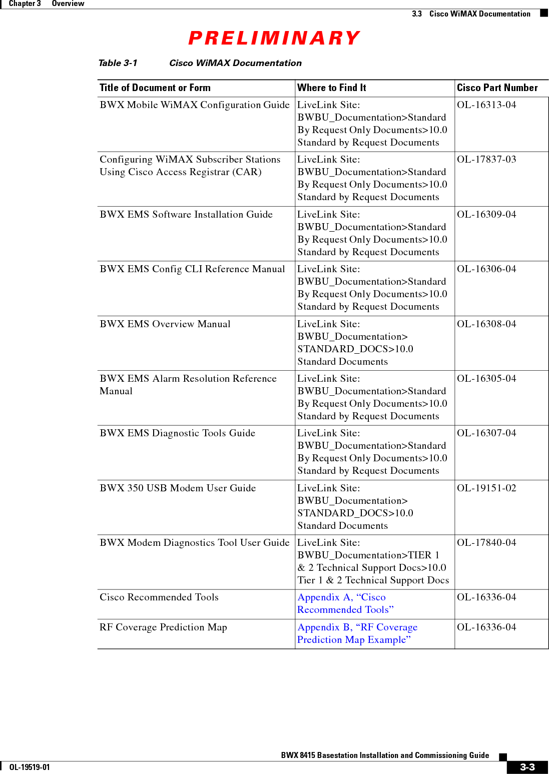
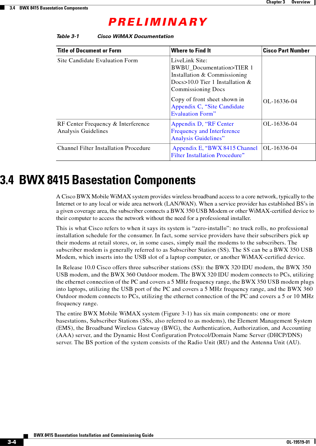
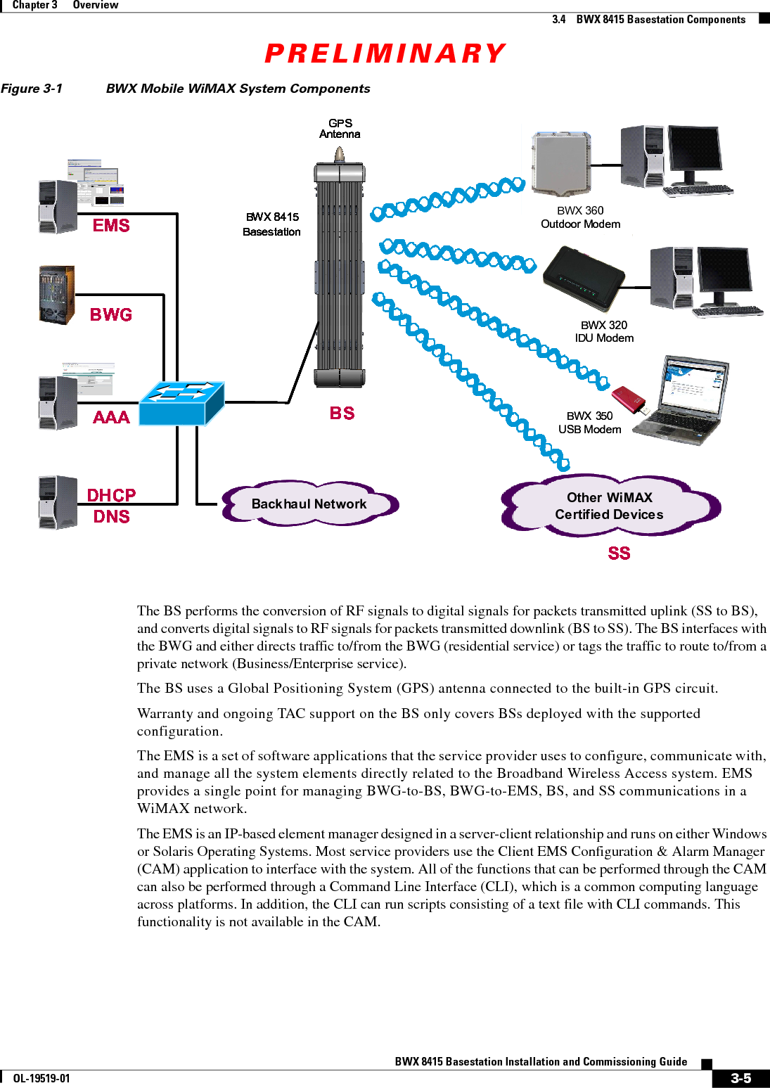
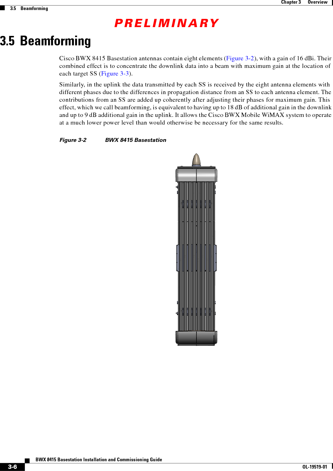
![PRELIMINARY3-2BWX 8415 Basestation Installation and Commissioning GuideOL-19519-01Chapter 3 Overview3.3 Cisco WiMAX Documentation3.3 Cisco WiMAX DocumentationTable 3-1 is a complete list of all documents and forms referenced in this guide. Cisco WiMAX documents are maintained on a LiveLink web page. When you completed your skills certification/qualification, you should have received your login instructions. If not, please contact the Cisco BWBU WiMAX Documentation team by emailing bwbu-docs@cisco.com. Refer to the following link for access to the appropriate LiveLink web page:BWBU_Documentation: https://tools.cisco.com/cws/livelink?func=ll&objid=4353291&objaction=browseNote that for some components in the WiMAX Profile C configuration, this guide refers to other Cisco documentation [for example, the Access Services Network Gateway (ASN-GW)]. When those components are referenced, a link to the www.cisco.com site is provided.Please make sure you have access to all necessary documentation prior to beginning the installation. Some documents and forms are software- or hardware-level sensitive. Always ensure you have the correct version of documents related to the system you are installing.Ta b l e 3-1 Cisco WiMAX DocumentationTitle of Document or Form Where to Find It Cisco Part NumberRelease Notes for BWX Mobile WiMAX Release 10.0LiveLink Site: BWBU_Documentation>Standard By Request Only Documents>10.0 Standard by Request DocumentsOL-19152-01BWX Mobile WiMAX Cell Site Planning GuideLiveLink Site: BWBU_Documentation>Standard By Request Only Documents>10.0 Standard by Request DocumentsOL-16328-04BWBU WiMAX Documentation Roadmap LiveLink Site: BWBU_Documentation> STANDARD_DOCS>10.0 Standard DocumentsOL-18211-03BWX Mobile WiMAX RF Planning Guide LiveLink Site: BWBU_Documentation>Standard By Request Only Documents>10.0 Standard by Request DocumentsOL-16333-04BWX Mobile WiMAX Migration Planning GuideLiveLink Site: BWBU_Documentation>Standard By Request Only Documents>10.0 Standard by Request DocumentsOL-16311-04BWX Mobile WiMAX Overview Manual LiveLink Site: BWBU_Documentation> STANDARD_DOCS>10.0 Standard DocumentsOL-16317-04](https://usermanual.wiki/Cisco-Systems/2484-B8415-R1.Installation-manual-Part-1/User-Guide-1234008-Page-26.png)