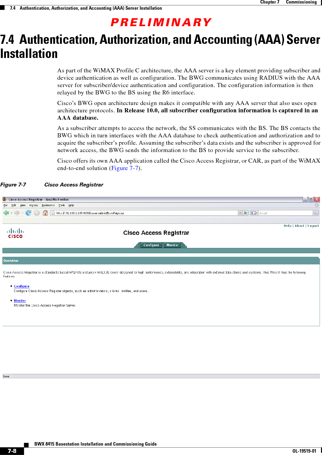
Cisco Systems 2484-B8415-R1 WiMAX Base Station, Broadband Wireless, 2.5/2.6 GHz User Manual Installation manual Part 4
Cisco Systems, Inc WiMAX Base Station, Broadband Wireless, 2.5/2.6 GHz Installation manual Part 4
Contents
- 1. Installation manual Part 1
- 2. Installation manual Part 2
- 3. Installation manual Part 3
- 4. Installation manual Part 4
- 5. Installation manual Part 5
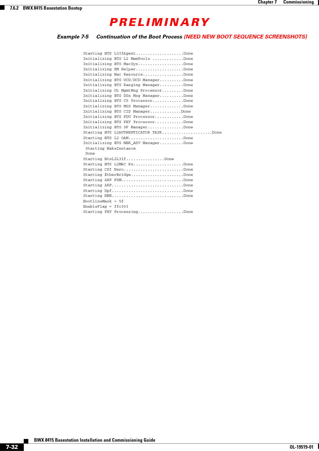
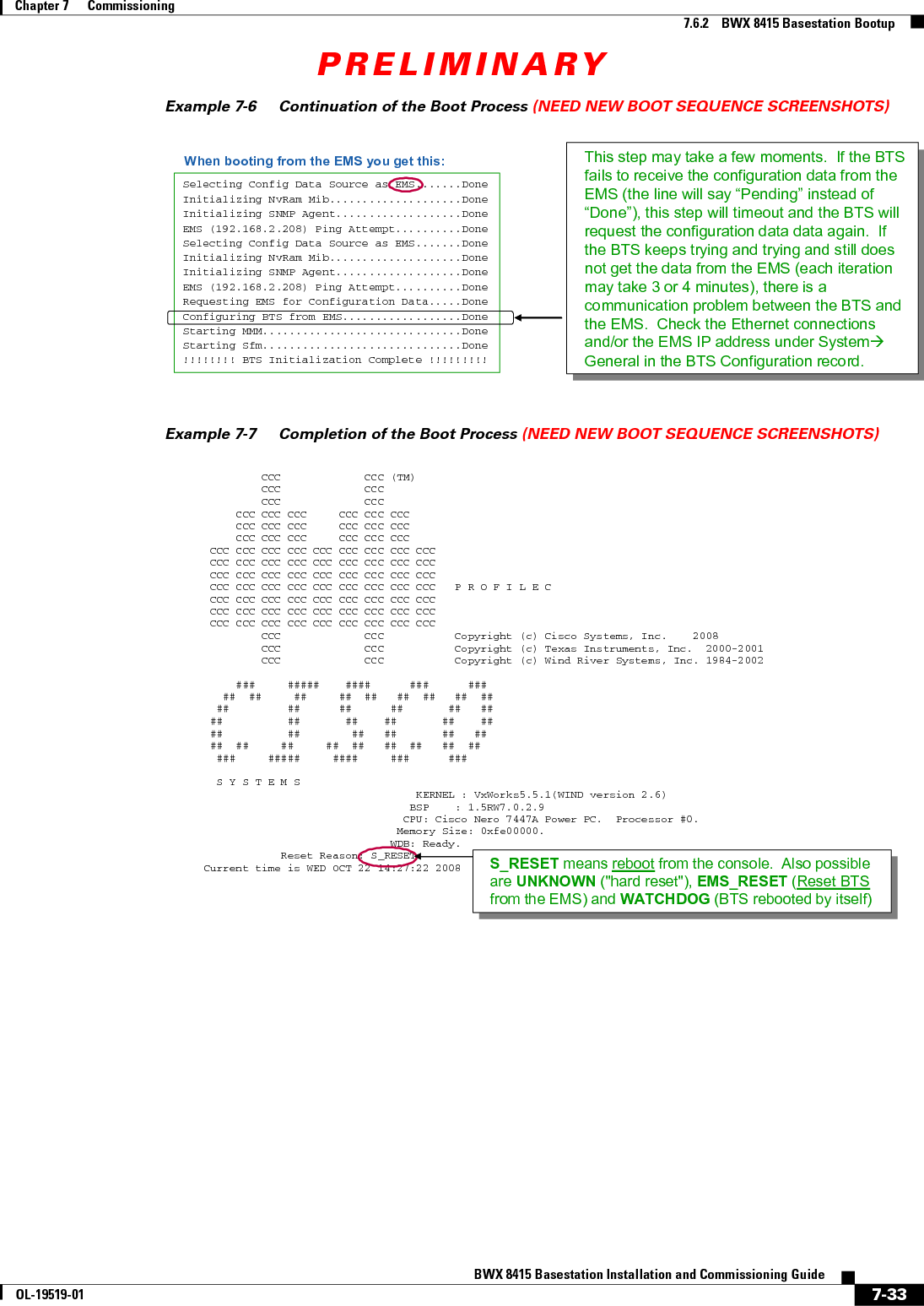
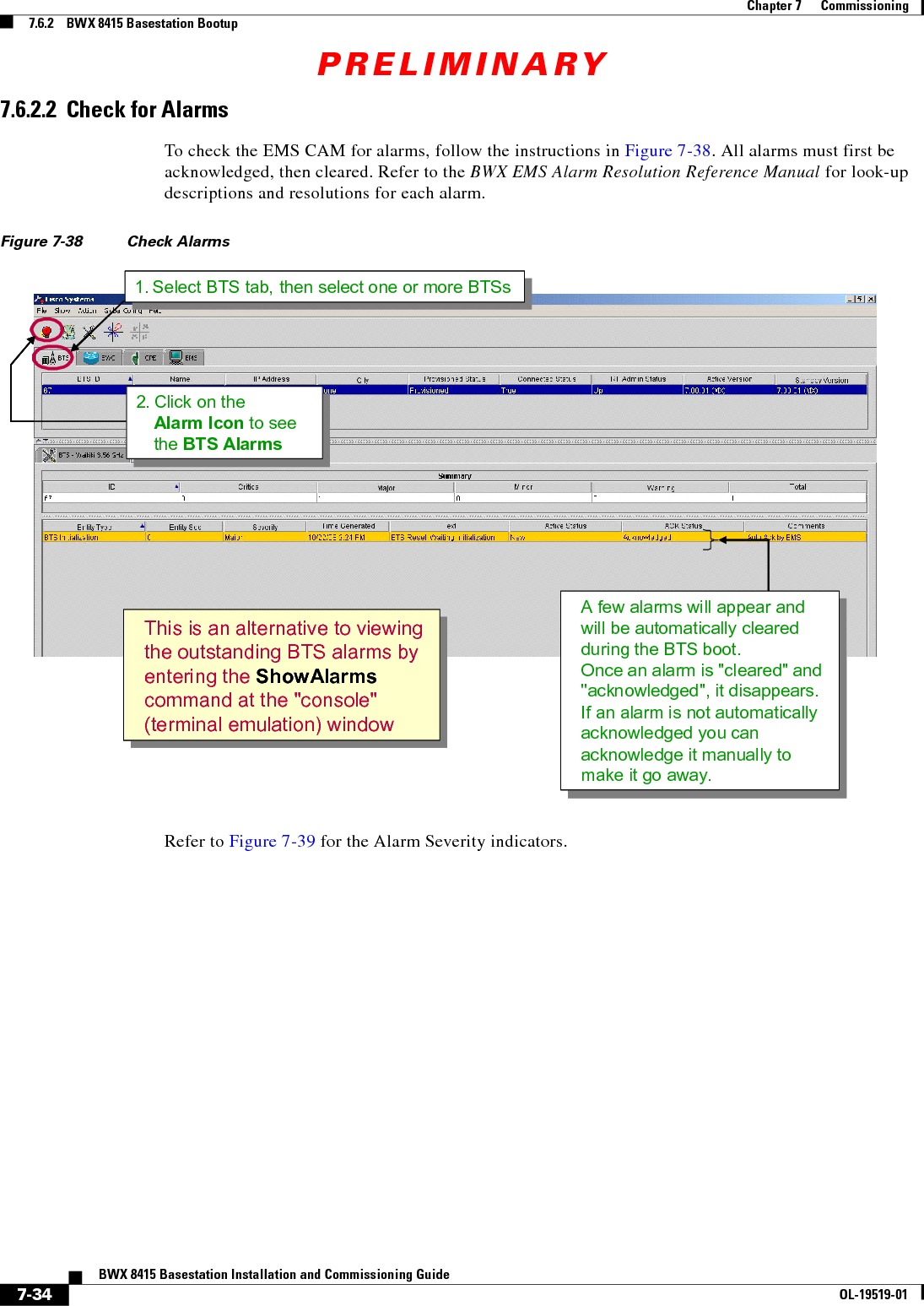
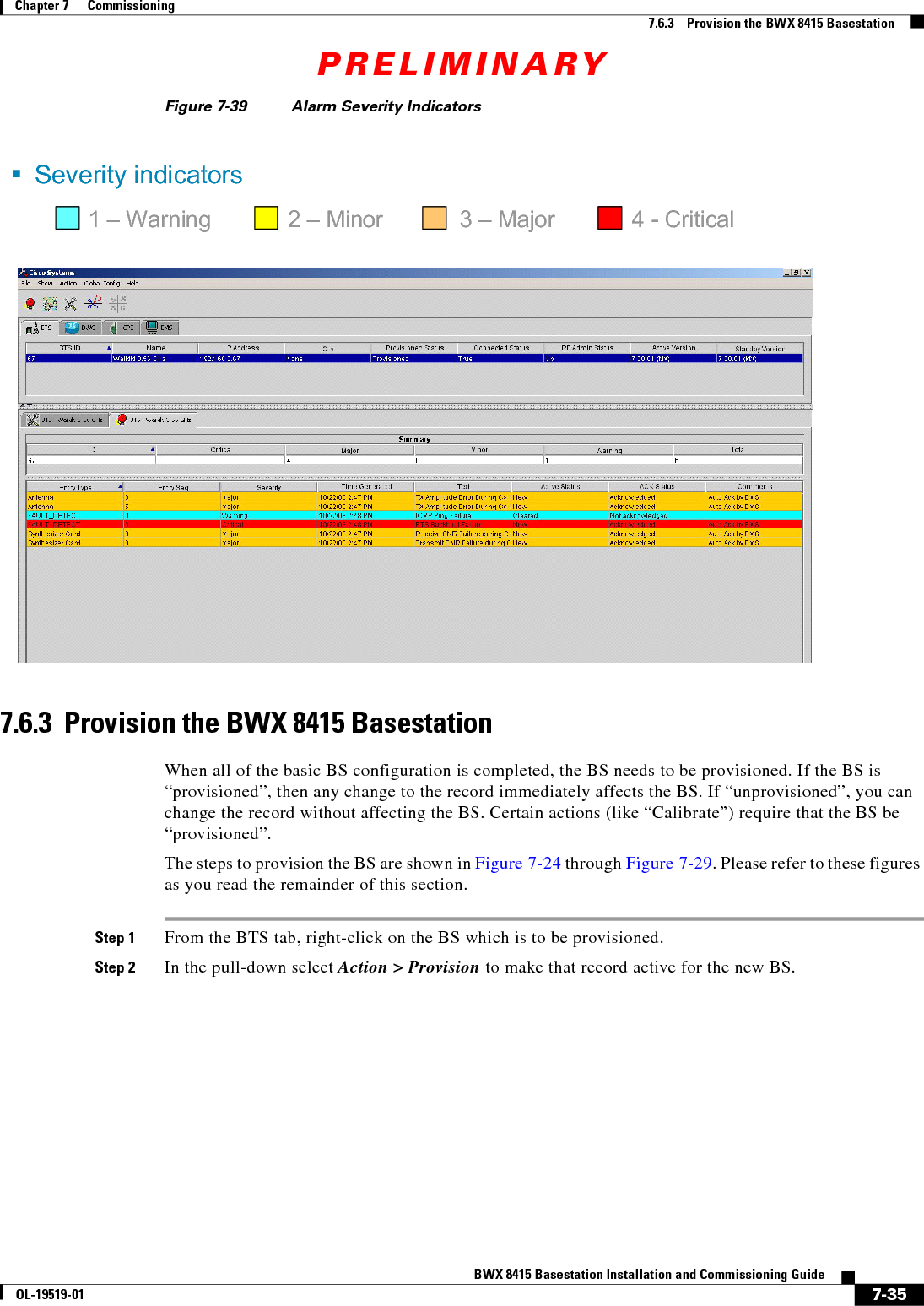
Installation manual Part 4
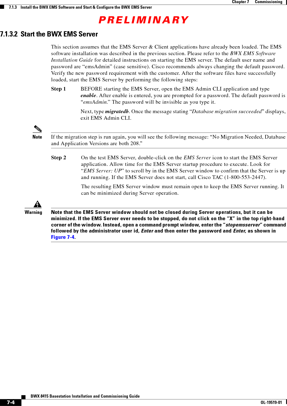
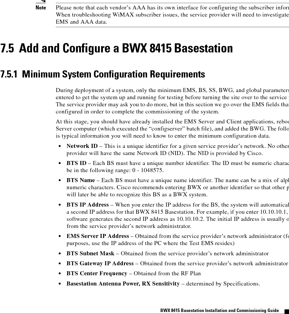
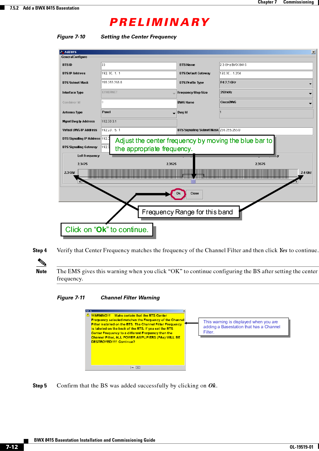
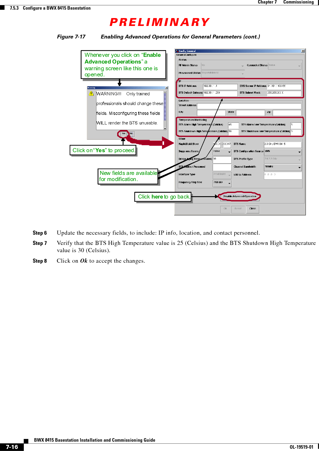
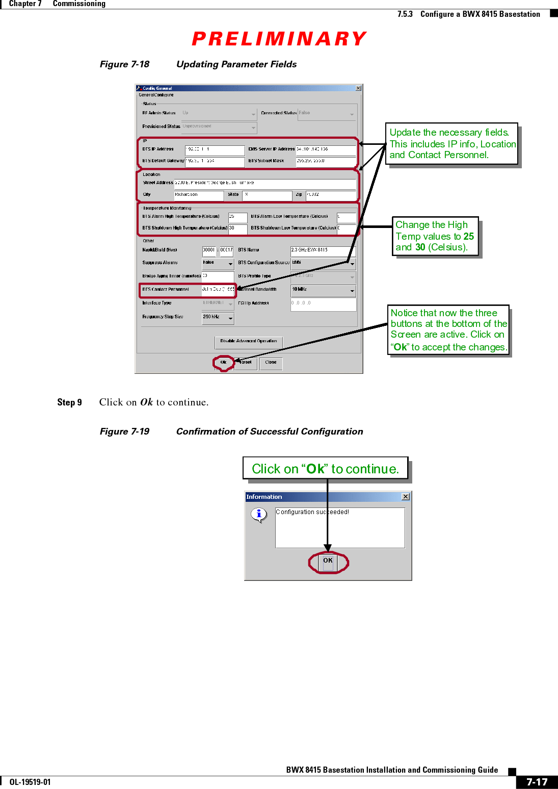
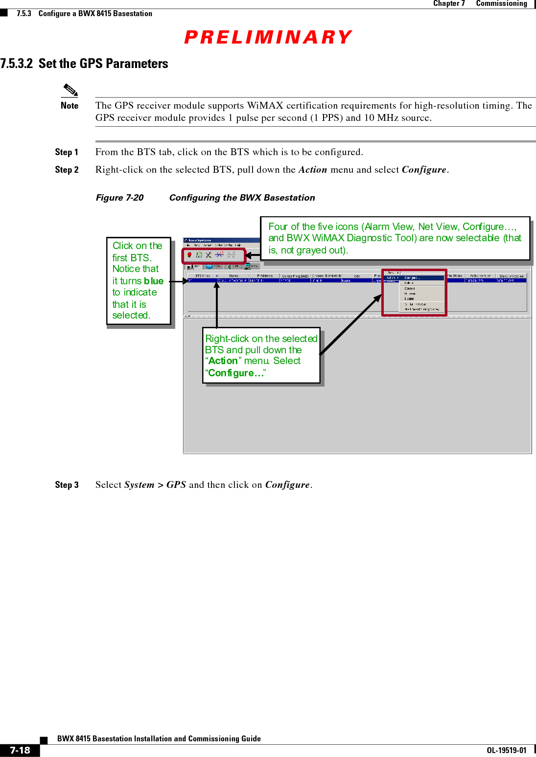
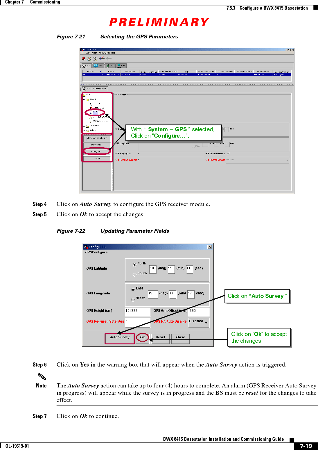
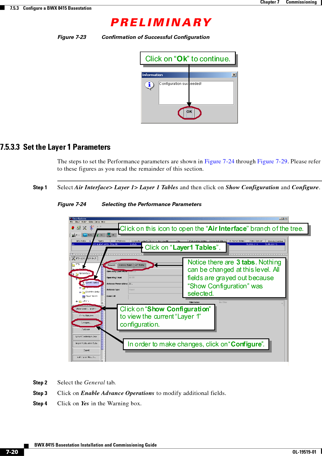
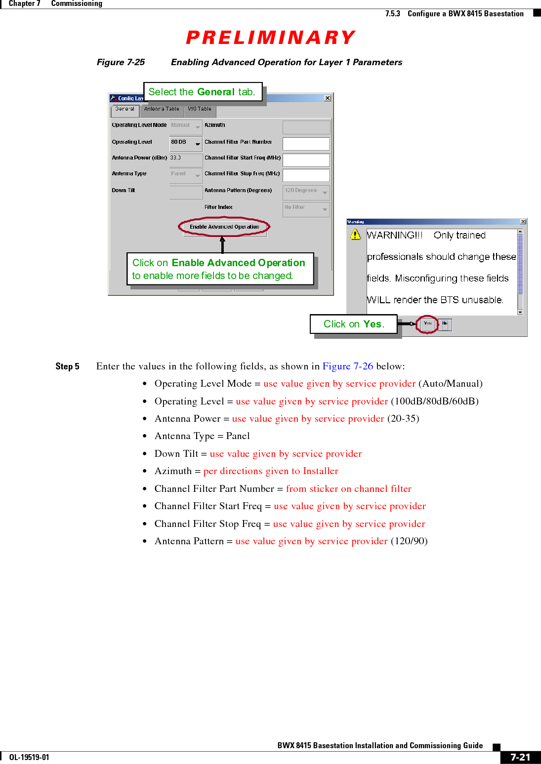
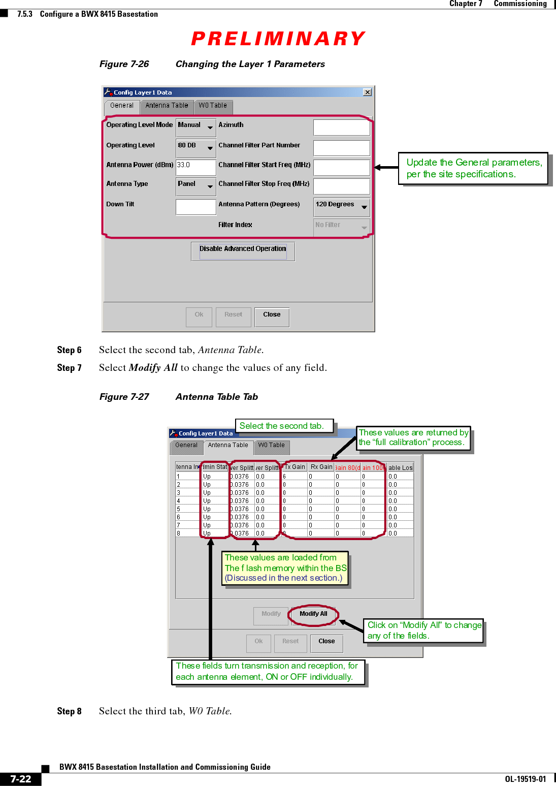
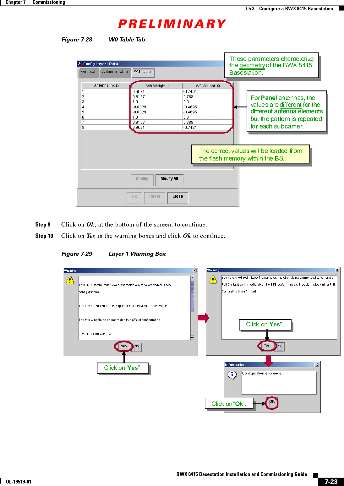
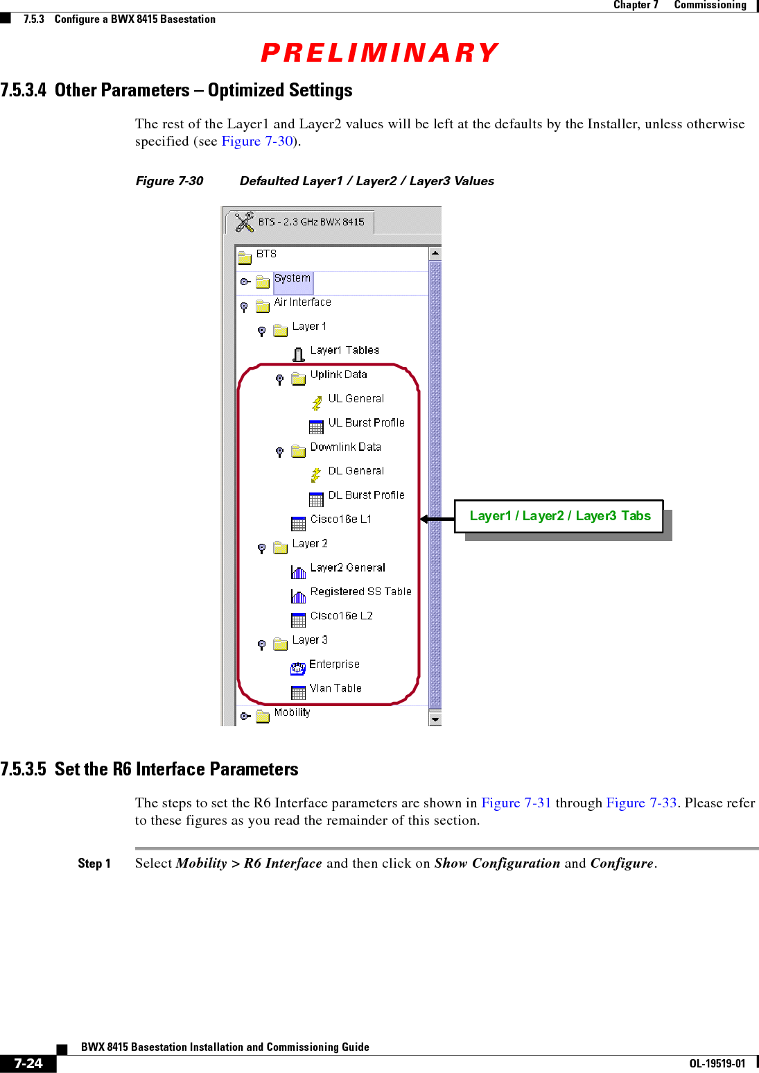
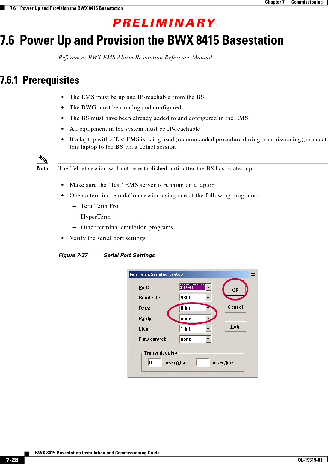
![PRELIMINARY7-30BWX 8415 Basestation Installation and Commissioning GuideOL-19519-01Chapter 7 Commissioning7.6.2 BWX 8415 Basestation BootupExample 7-2 System Boot Sequence (NEED NEW BOOT SEQUENCE SCREENSHOTS) Step 6 Enter p to verify(Example 7-3).Step 7 When all changes have been made, type @ and hit <Enter> to resume the boot process (Example 7-3).Auto-booting (Enter "config" for setup)... 17config[Navini Boot]: [Navini Boot]: [Navini Boot]: pdate and time : 10/22/2008[14:21] autoboot countdown : delayed ems inet : 192.168.1.220 snmp community : public traffic path : enetmac address : 00:04:6a:00:3b:ccip on enet (active) : 192.168.1.100 ip on enet (standby) : 192.168.1.101netmask on enet : 255.255.248.0 mgmt vlan id|priority: 1:0 [1-4094]:[0-7]ip on backplane : 10.0.0.1 gateway on enet : 192.168.1.1 [Navini Boot]: [Navini Boot]: [Navini Boot]: cdate and time : 10/22/2008[14:22] MM/dd/yyyy[hh:mm] autoboot countdown : delayed [quick|delayed] ems inet : 192.168.1.220 192.168.2.208snmp community : public traffic path : enetmac address : 00:04:6a:00:3b:ccip on enet (active) : 192.168.1.100 192.168.2.67ip on enet (standby) : 192.168.1.101netmask on enet : 255.255.248.0 255.255.255.0mgmt vlan id|priority: 1:0 [1-4094]:[0-7]ip on backplane : 10.0.0.1 gateway on enet : 192.168.1.1 192.168.2.1[Navini Boot]: At this prompt, type "config" before the autoboot countdown expires (by default it is set to "delayed" lasting 20 seconds)At the Navini Boot prompt, type "p" and hit <Enter> to check the current value of the parametersIdentify the bootlineparameters that need to be changedAt the Navini Boot prompt, type “c" and hit <Enter> to change the current value of the parametersChange the desired parameters, one at a time](https://usermanual.wiki/Cisco-Systems/2484-B8415-R1.Installation-manual-Part-4/User-Guide-1234011-Page-30.png)
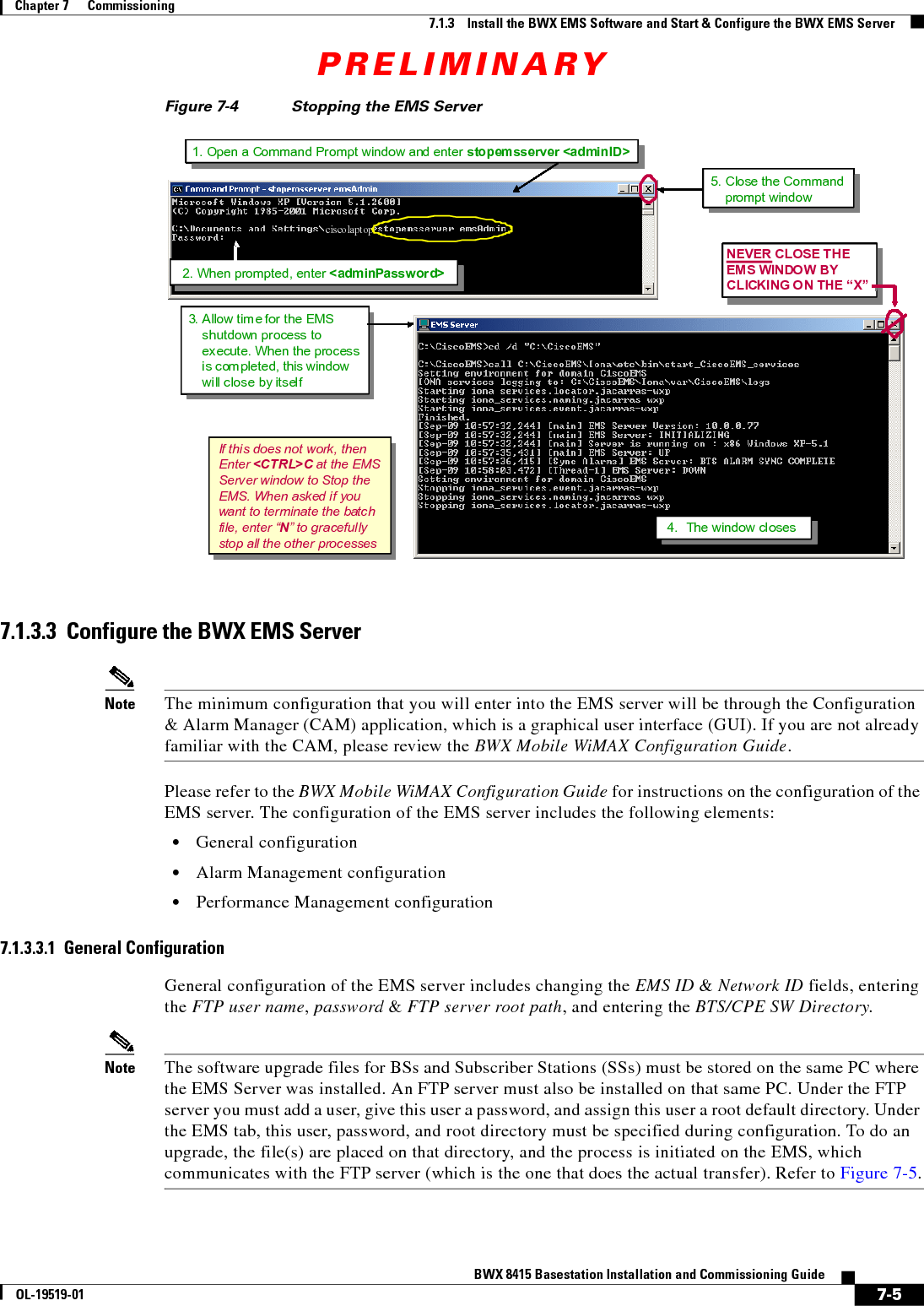
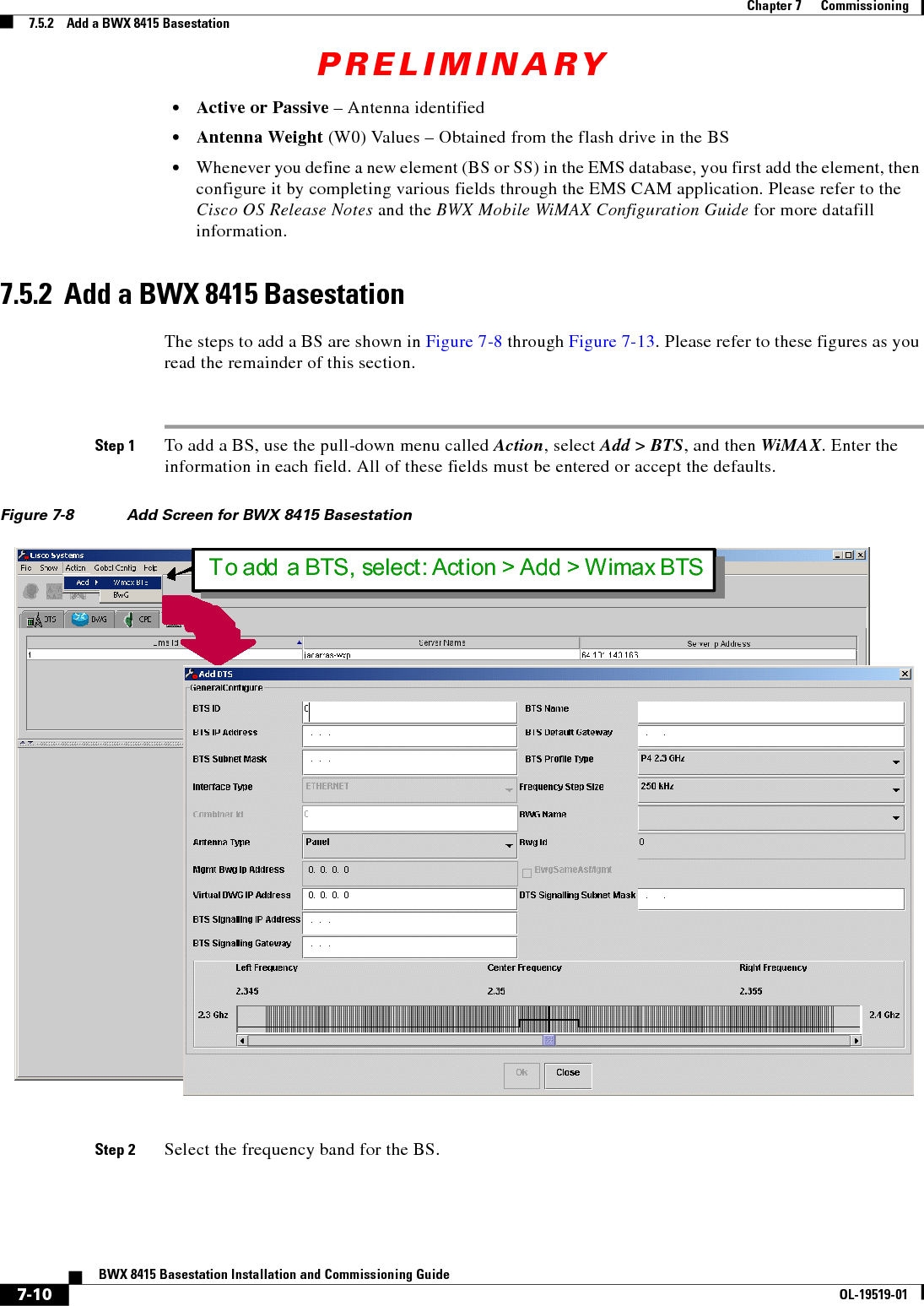
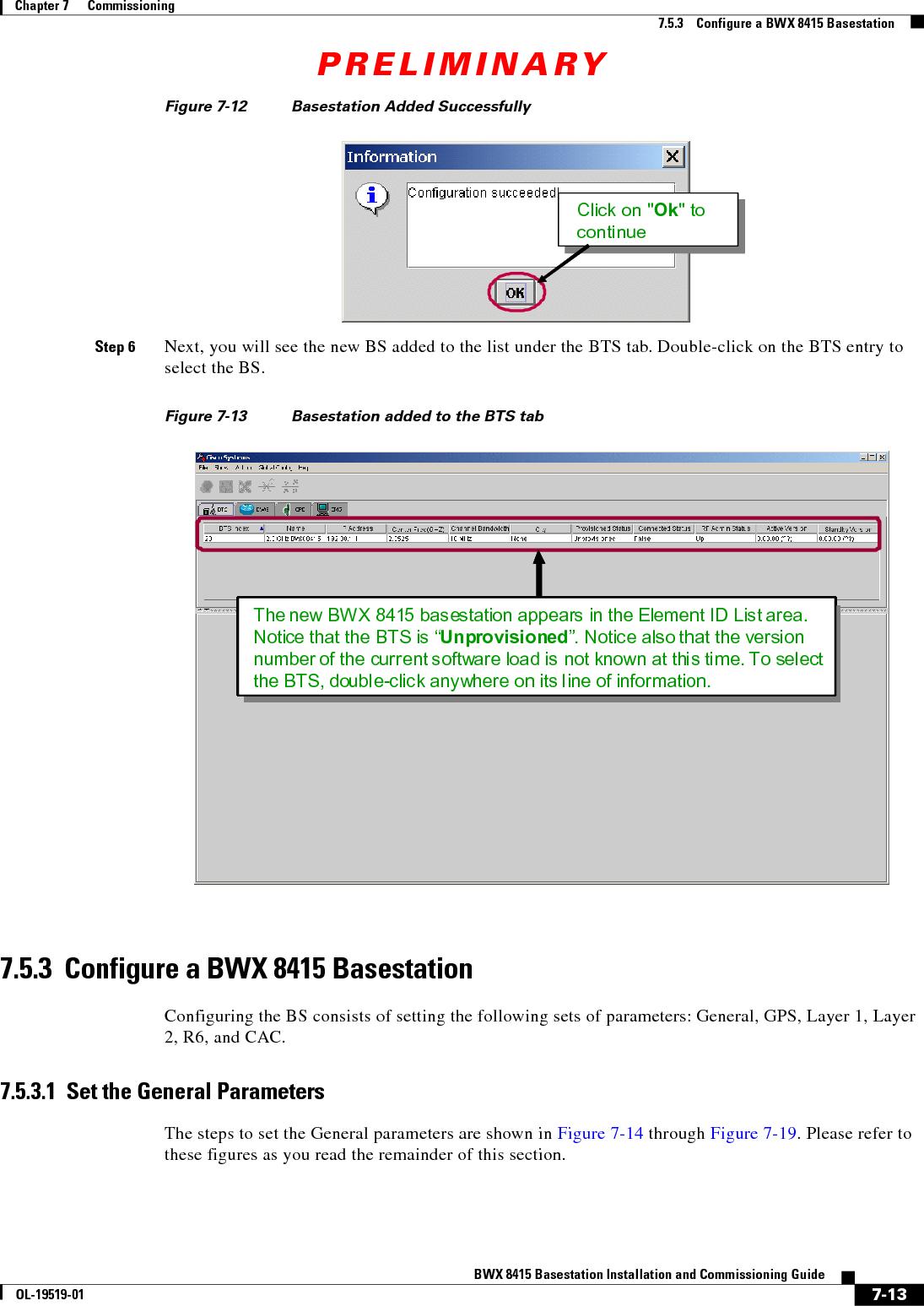
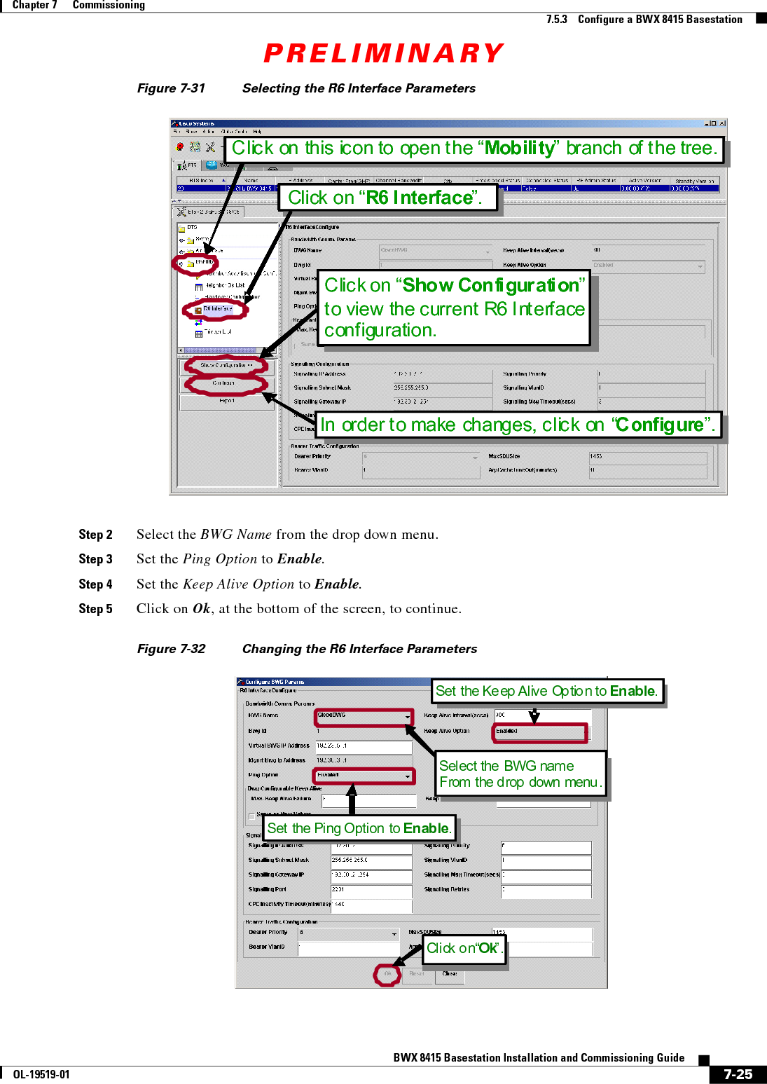
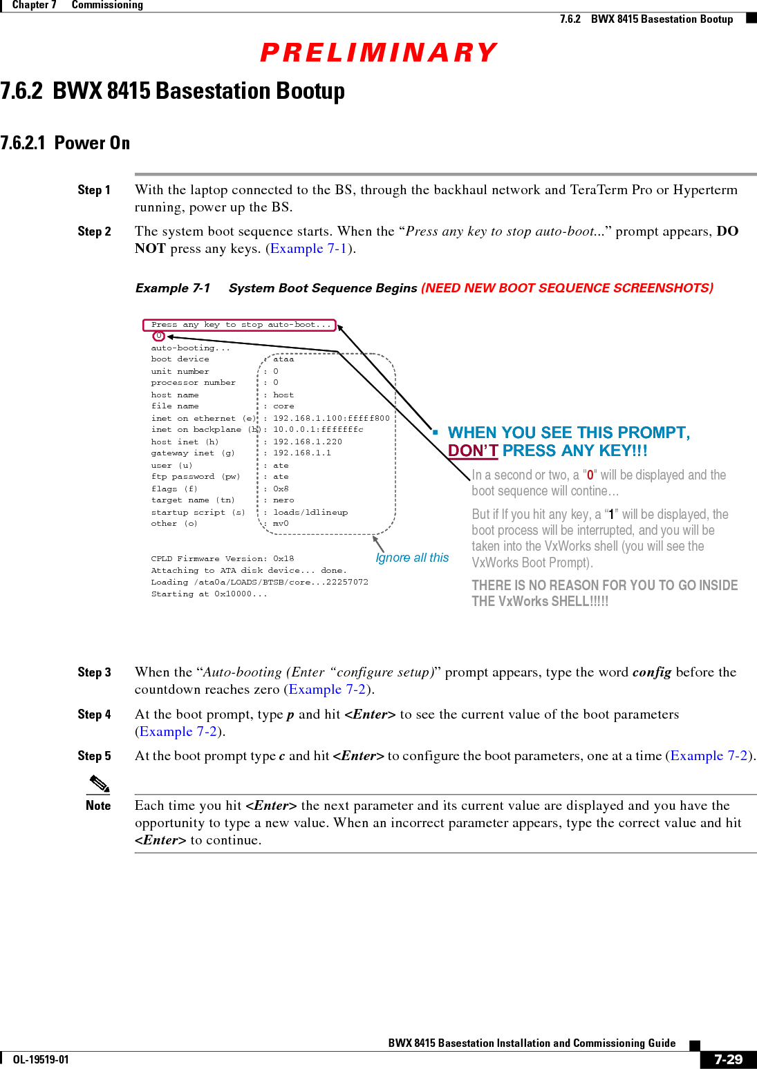
![PRELIMINARY7-31BWX 8415 Basestation Installation and Commissioning GuideOL-19519-01Chapter 7 Commissioning7.6.2 BWX 8415 Basestation BootupExample 7-3 Changing the Boot Parameter Values (NEED NEW BOOT SEQUENCE SCREENSHOTS) Example 7-4 Continuation of the Boot Process (NEED NEW BOOT SEQUENCE SCREENSHOTS) [Navini Boot]: pdate and time : 10/22/2008[14:22] autoboot countdown : delayed ems inet : 192.168.2.208 snmp community : public traffic path : enetmac address : 00:04:6a:00:3b:ccip on enet (active) : 192.168.2.67 ip on enet (standby) : 192.168.2.68netmask on enet : 255.255.255.0 mgmt vlan id|priority: 1:0 [1-4094]:[0-7]ip on backplane : 10.0.0.1 gateway on enet : 192.168.2.1 [Navini Boot]:[Navini Boot]: @CPLD Firmware Version: 0x18Starting File System......................DoneMounting Drive /dev0......................DoneStarting TCP/IP Stack.....................DoneAttached TCP/IP interface to mv unit 0Attaching interface lo0...doneMounting Remote Filesystem................Default Route added,Gateway = 192.168.2.1Host 172.31.26.201 added to host table ...........DoneStarting Telnet Daemon....................DoneStarting Load Monitoring Tools............DoneLoading symbol table from /cf/LOADS/BTSB/core.sym ..DoneStarting WDB Tools........................DoneStarting Target Shell.....................DoneInitializing System Logger................DoneAt the prompt, type "p"and hit <Enter> to verify the changesEnter "c" for changes; "@" to continue33333333Programming System Support Fpga ..........DoneProgramming Shazam Fpga ..................DoneProgramming Aphex Fpga ...................DoneProgramming RF Fpga ......................DoneStarting L1 DSP Bootloader ........................WIMAX APPCP Image Path = /cf/LOADS/BTSB/CP01_MX_IMAGE.bin ... : File open - SuccessPP01 Image Path = /cf/LOADS/BTSB/CCP01_MX_IMAGE.bin ... : File open - SuccessXP Image Path = /cf/LOADS/BTSB/XP_MX_IMAGE.bin ... : File open - SuccessReset Vals = 0------------------- DSP STATUS REGISTERS ---------------------------------------------------------------------------------------------|GDSW Ver|ResetReg|AUX|PP01|PP23|PP45|PP67|CP01|CP23|CP45|CP67|CP89|--------------------------------------------------------------------| 98 | 0 | b | b | 0 | 0 | 0 | b | b | b | b | 0 |--------------------------------------------------------------------Starting MPC184 Security Processor........DoneEnable All: XP, CCP, [4]CPs (DSP Bootline Flag: 0x5f)...BootlineMask = 5f Calling OAM Mem Pool##########Starting L2 Tasks############START BtsL2L3If::BtsL2L3If OAM Mem Pool... DoneInitializing GDSW Parameters..............DoneStarting MCE..............................DoneStarting AsnCom...........................DoneStarting AsnComRx.........................DoneStarting MME..............................DoneInitializing OAM MemPools .............DoneInitializing L2 Applications.....................DoneInitializing Doubly List..................DoneStarting BTS L2 L1If .....................Done](https://usermanual.wiki/Cisco-Systems/2484-B8415-R1.Installation-manual-Part-4/User-Guide-1234011-Page-31.png)