Cisco Systems 2484-B8415-R1 WiMAX Base Station, Broadband Wireless, 2.5/2.6 GHz User Manual Installation manual Part 2
Cisco Systems, Inc WiMAX Base Station, Broadband Wireless, 2.5/2.6 GHz Installation manual Part 2
Contents
- 1. Installation manual Part 1
- 2. Installation manual Part 2
- 3. Installation manual Part 3
- 4. Installation manual Part 4
- 5. Installation manual Part 5
Installation manual Part 2
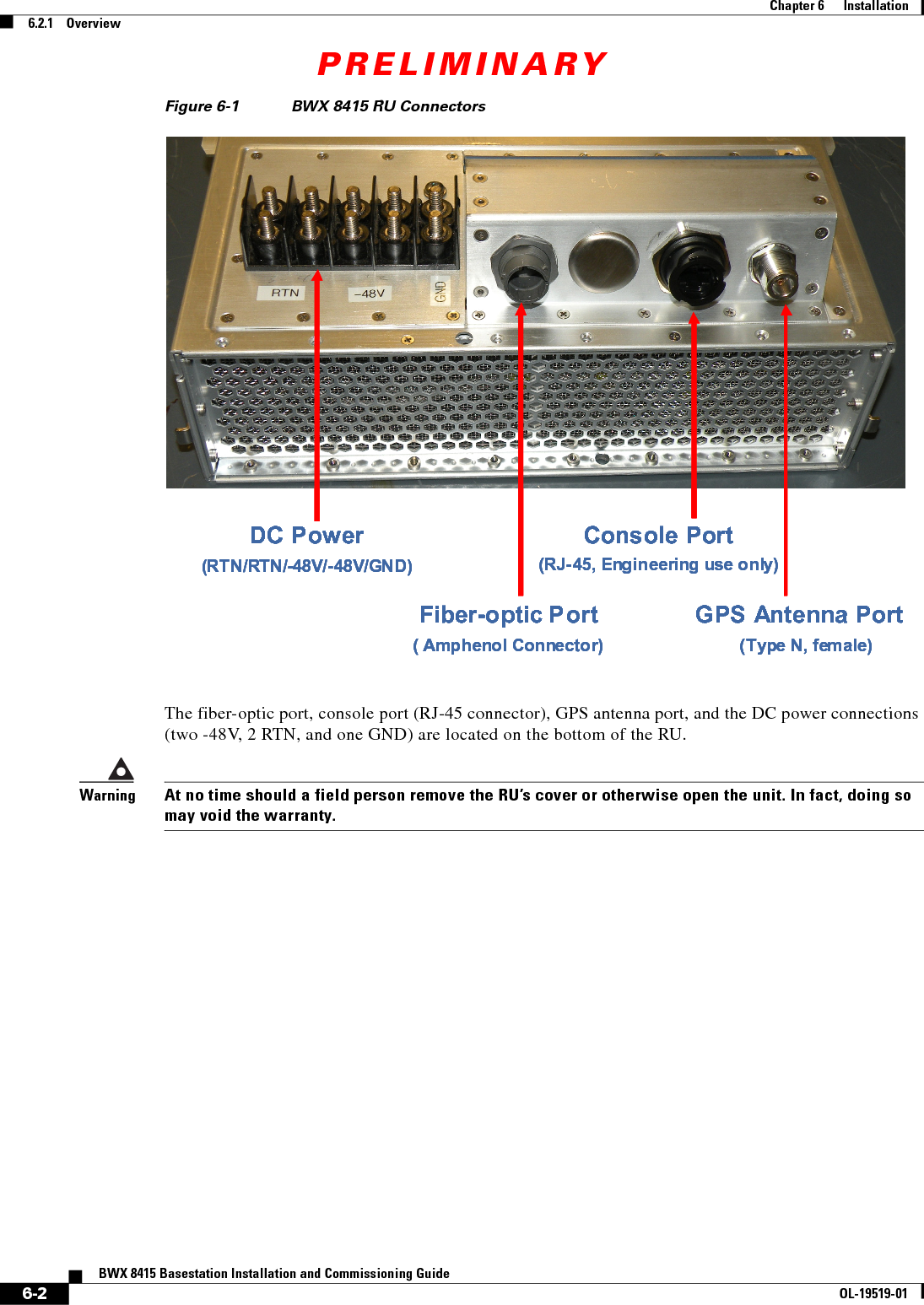
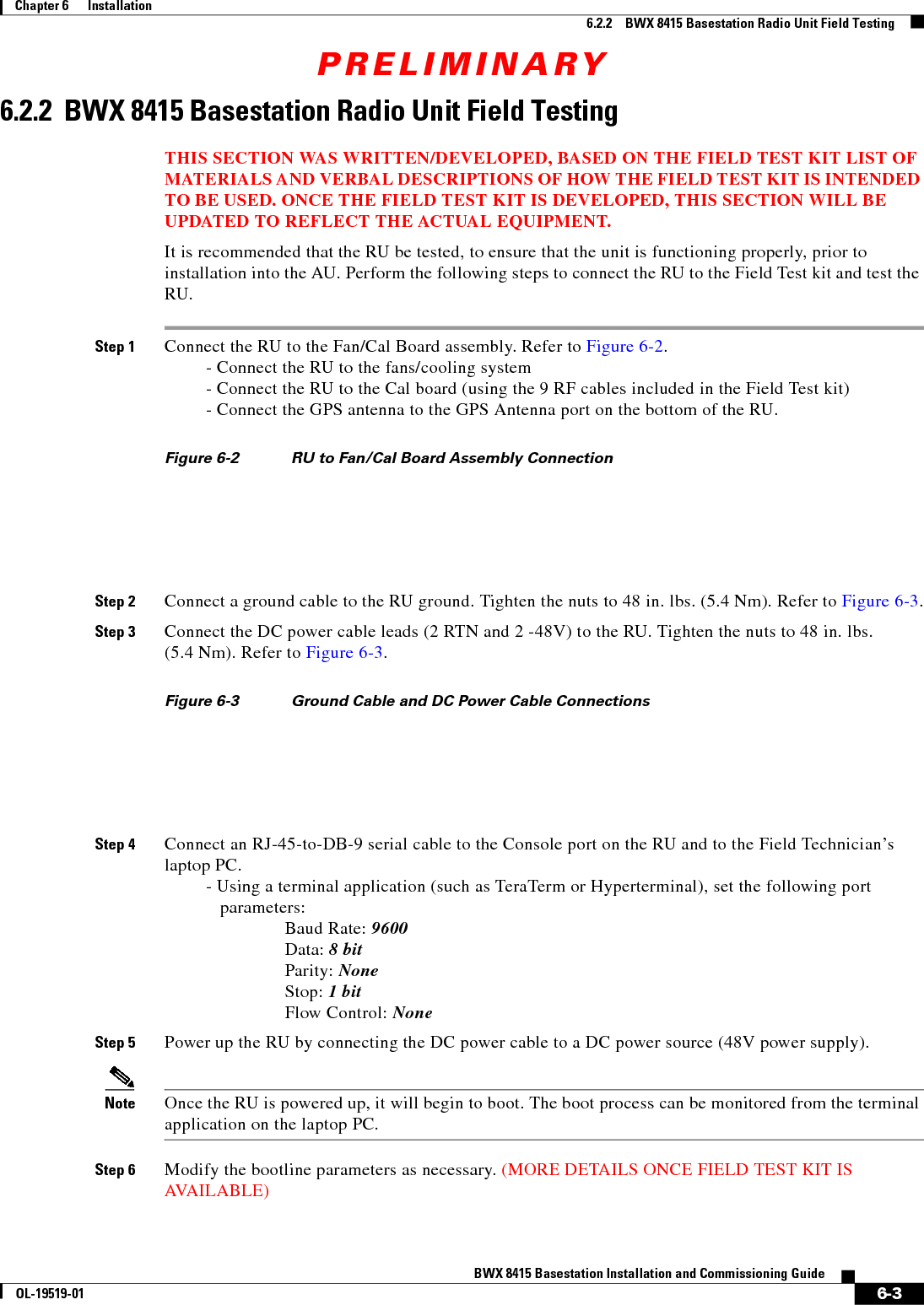
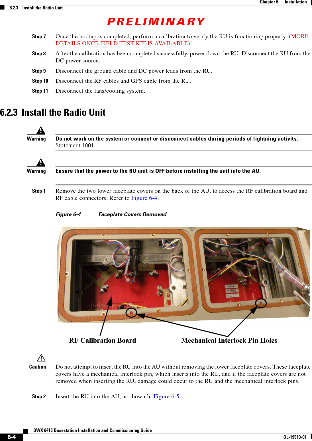
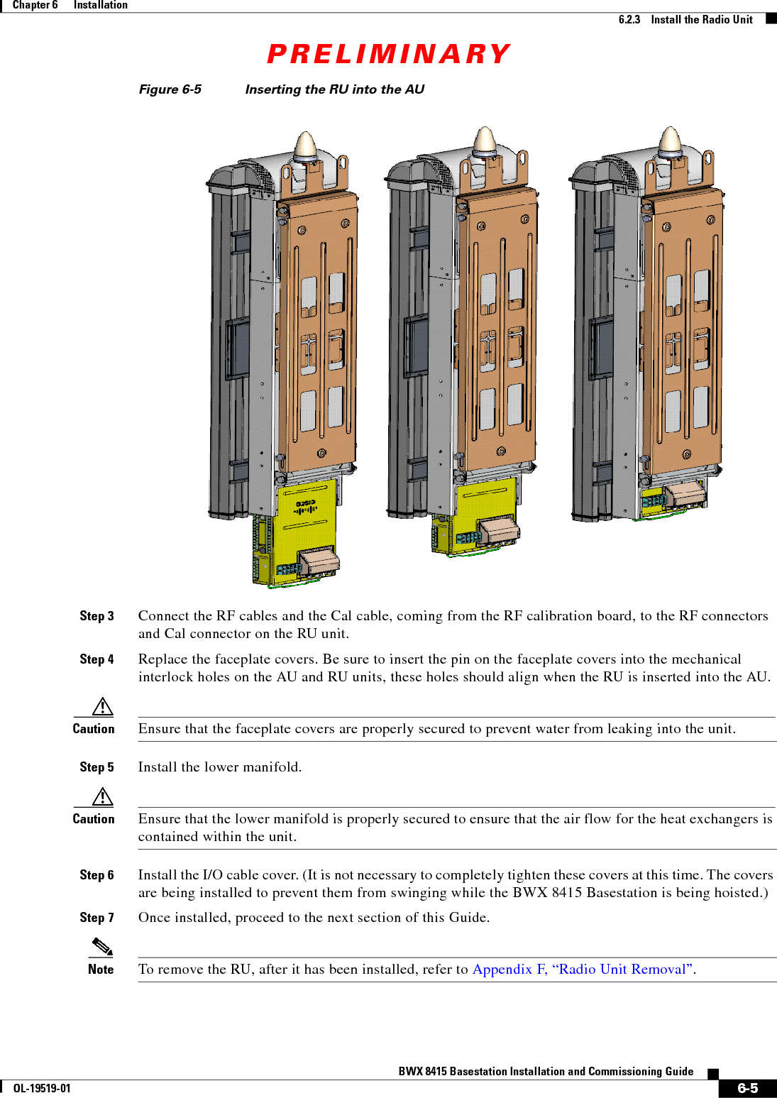
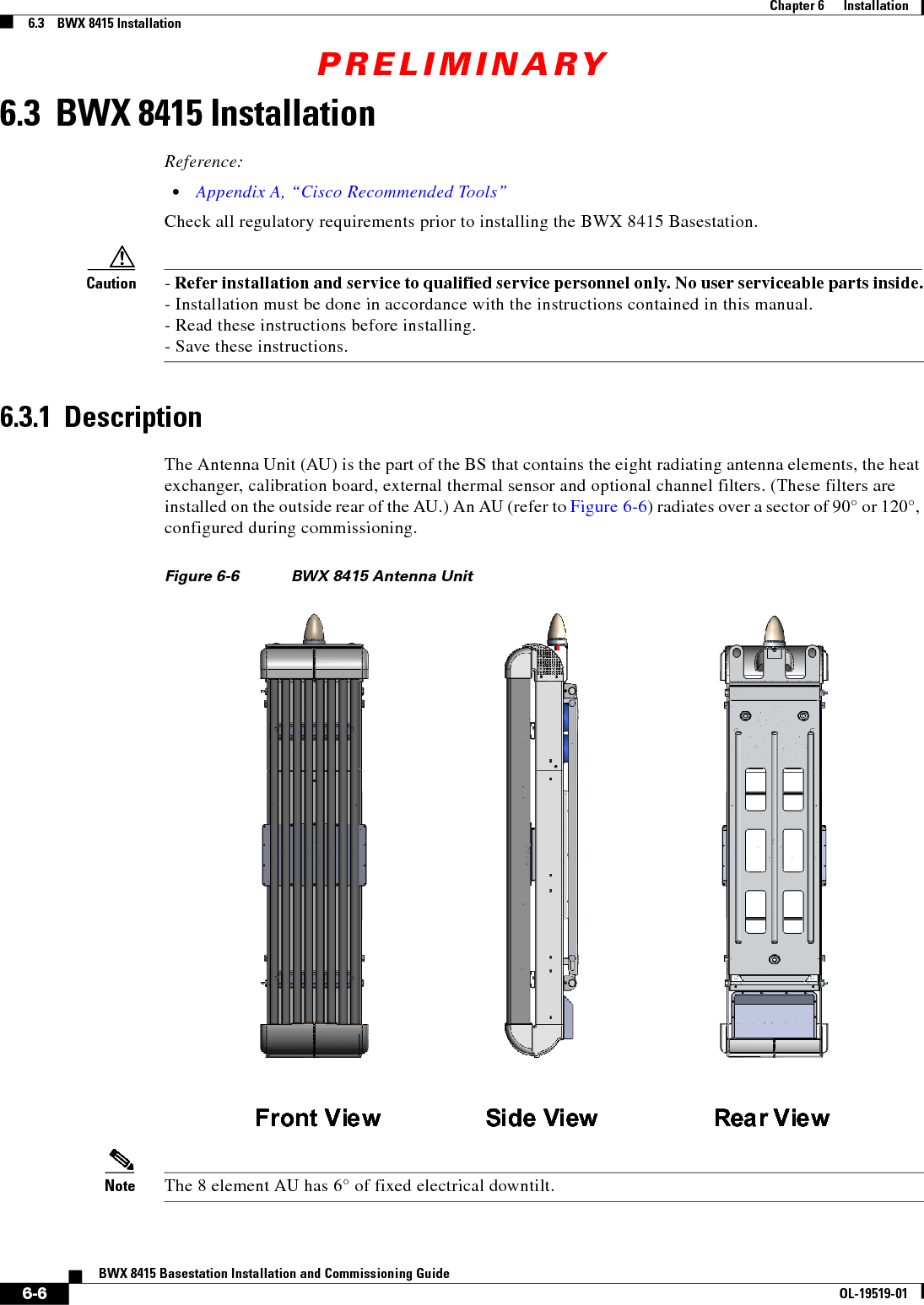
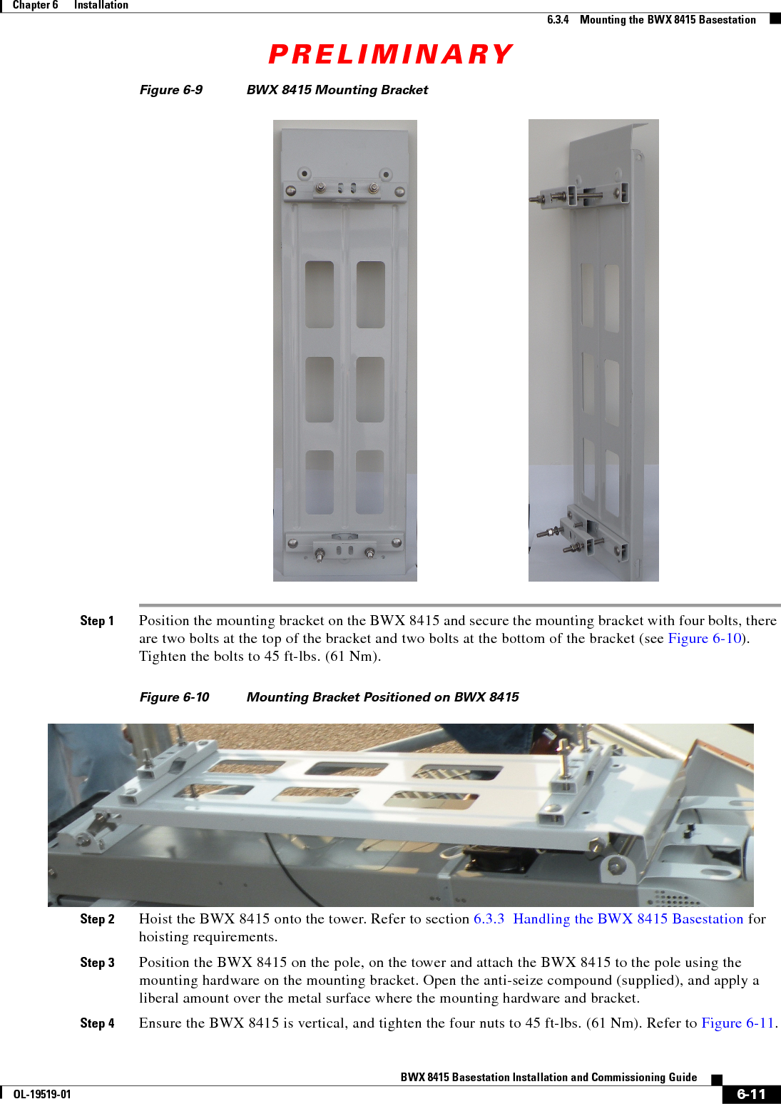
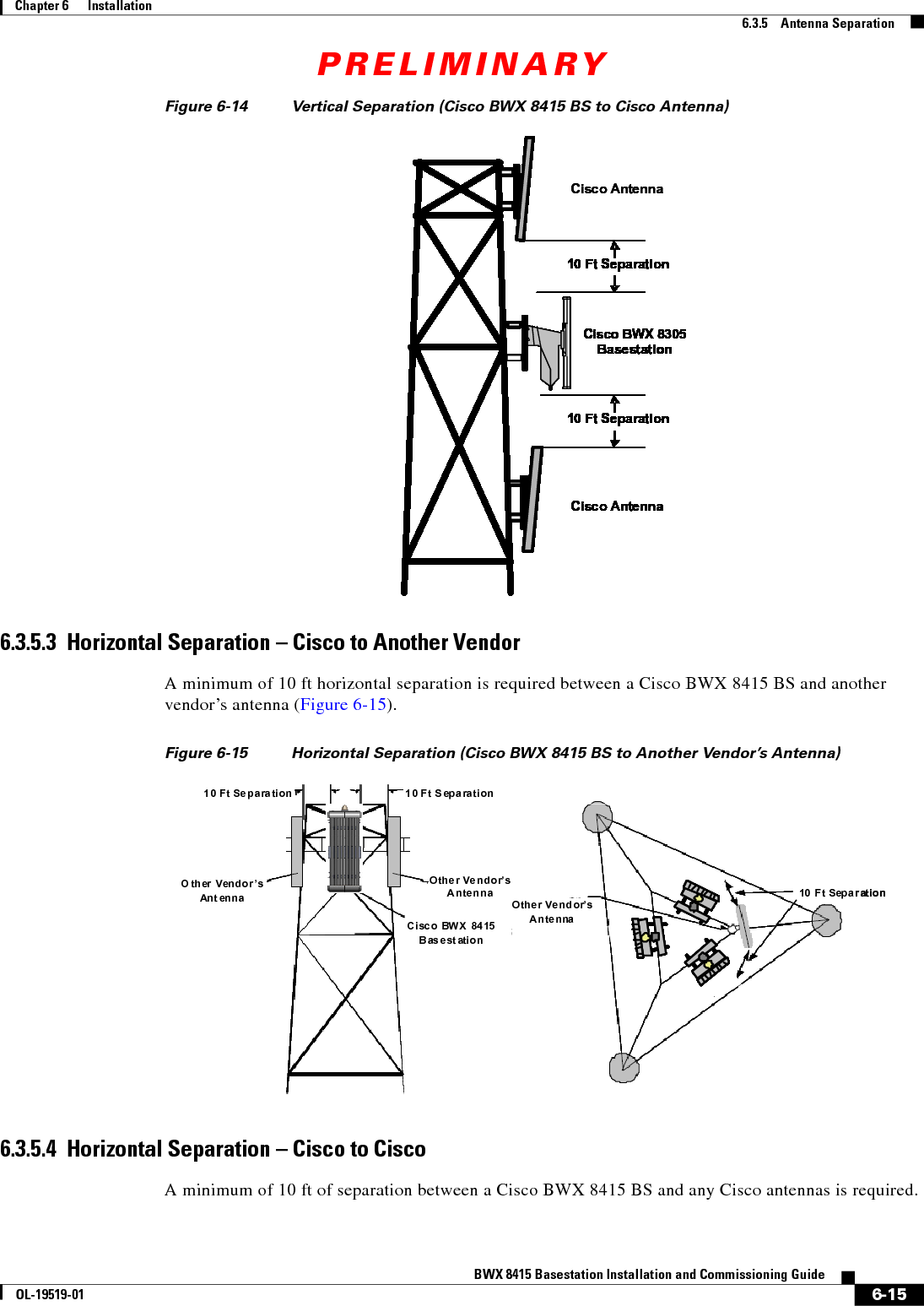
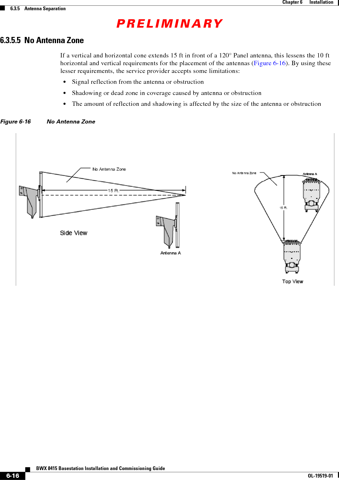
![PRELIMINARY6-10BWX 8415 Basestation Installation and Commissioning GuideOL-19519-01Chapter 6 Installation6.3.4 Mounting the BWX 8415 BasestationWarningIn order to comply with radio frequency (RF) exposure limits, the antennas for this product should be positioned no less than 6.56 ft (2 m) from your body or nearby persons. Statement 339WarningDo not work on the system or connect or disconnect cables during periods of lightning activity. Statement 1001WarningOnly trained and qualified personnel should be allowed to install, replace, or service this equipment. Statement 1030WarningInstallation of the equipment must comply with local and national electrical codes. Statement 10746.3.4.1 Mounting the BWX 8415 on a WallWhen installing the BWX 8415 on an outdoor wall, ensure that the wall and mounting hardware (anchor bolts) chosen to mount the BS are capable of supporting both the static weight of the BS and the lateral load, resulting from wind loading and that the installation adheres to all local building and safety codes.Note The following specifications should be helpful in planning the wall mounted installation: Dimensions: 2.3 & 2.5 GHz - 62 X 20 X 12 in (158 X 50 X 30 cm) 3.5 GHz - 62 X 14.5 X 12 in (158 X 37 X 30 cm) Weight: 110 lbs. (50 kg) w/o filters [does not include the external cable strain relief] Wind Loading: 170 lbs. with 100 mile/h lateral thrust (77 kg with 161 km/h lateral thrust) Ice Loading: The BS can operate with up to .75 in (1.9 cm) thick buildup of ice without sustaining damage.6.3.4.2 Mounting the BWX 8415 on a PoleWhen installing the BWX 8415 on a pole, keep in mind that the mounting bracket supports metal, wood, or fiberglass poles from 3 - 4.5 inches (7.6 - 11.4 cm) in diameter. Figure 6-9 illustrates the mounting bracket.](https://usermanual.wiki/Cisco-Systems/2484-B8415-R1.Installation-manual-Part-2/User-Guide-1234009-Page-10.png)