Cisco Systems 2484-B8415-R1 WiMAX Base Station, Broadband Wireless, 2.5/2.6 GHz User Manual Installation manual Part 2
Cisco Systems, Inc WiMAX Base Station, Broadband Wireless, 2.5/2.6 GHz Installation manual Part 2
Contents
- 1. Installation manual Part 1
- 2. Installation manual Part 2
- 3. Installation manual Part 3
- 4. Installation manual Part 4
- 5. Installation manual Part 5
Installation manual Part 2
CHAPTER
PRELIMINARY
6-1
BWX 8415 Basestation Installation and Commissioning Guide
OL-19519-01
6
Installation
6.1 Inventory
The first thing an installer physically does once onsite is to check to see that all equipment and materials
have arrived, as well as to make sure all necessary documents and forms are available.
6.2 BWX 8415 Basestation Radio Unit (RU) Installation
6.2.1 Overview
Caution Only trained and qualified personnel should be allowed to install, replace, or service this
equipment. Statement 1030
Caution - Refer installation and service to qualified service personnel only. No user serviceable parts inside.
- Installation must be done in accordance with the instructions contained in this manual.
- Read these instructions before installing.
- Save these instructions.
Warning
Installation of the equipment must comply with local and national electrical codes.
Statement 1074
The Radio Unit (RU) is a lightweight unit that connects easily with the Antenna Unit (AU) to form the
complete BWX 8415 Basestaion (BS). All customer accessible connectors will be located on the bottom
of the RU (Figure 6-1).
Note that the circuit cards inside the BS are not field replaceable. Therefore, if a severe fault occurs, the
entire unit is removed and replaced. The design intent is to cut down on the time it takes to troubleshoot
or otherwise have a field support person onsite.
PRELIMINARY
6-2
BWX 8415 Basestation Installation and Commissioning Guide
OL-19519-01
Chapter 6 Installation
6.2.1 Overview
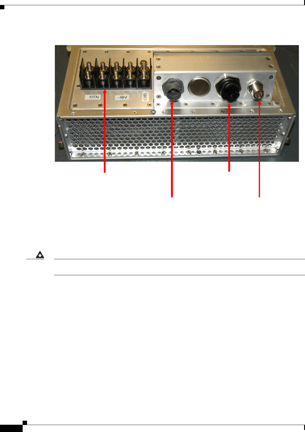
Figure 6-1 BWX 8415 RU Connectors
The fiber-optic port, console port (RJ-45 connector), GPS antenna port, and the DC power connections
(two -48V, 2 RTN, and one GND) are located on the bottom of the RU.
Warning
At no time should a field person remove the RU’s cover or otherwise open the unit. In fact, doing so
may void the warranty.
GPS Antenna Port
(Type N, female)
DC Power
(RTN/RTN/-48V/-48V/GND)
Console Port
(RJ-45, Engineering use only)
Fiber-optic Port
( Amphenol Connector)
GPS Antenna Port
(Type N, female)
GPS Antenna Port
(Type N, female)
DC Power
(RTN/RTN/-48V/-48V/GND)
DC Power
(RTN/RTN/-48V/-48V/GND)
Console Port
(RJ-45, Engineering use only)
Console Port
(RJ-45, Engineering use only)
Fiber-optic Port
( Amphenol Connector)
Fiber-optic Port
( Amphenol Connector)

PRELIMINARY
6-3
BWX 8415 Basestation Installation and Commissioning Guide
OL-19519-01
Chapter 6 Installation
6.2.2 BWX 8415 Basestation Radio Unit Field Testing
6.2.2 BWX 8415 Basestation Radio Unit Field Testing
THIS SECTION WAS WRITTEN/DEVELOPED, BASED ON THE FIELD TEST KIT LIST OF
MATERIALS AND VERBAL DESCRIPTIONS OF HOW THE FIELD TEST KIT IS INTENDED
TO BE USED. ONCE THE FIELD TEST KIT IS DEVELOPED, THIS SECTION WILL BE
UPDATED TO REFLECT THE ACTUAL EQUIPMENT.
It is recommended that the RU be tested, to ensure that the unit is functioning properly, prior to
installation into the AU. Perform the following steps to connect the RU to the Field Test kit and test the
RU.
Step 1 Connect the RU to the Fan/Cal Board assembly. Refer to Figure 6-2.
- Connect the RU to the fans/cooling system
- Connect the RU to the Cal board (using the 9 RF cables included in the Field Test kit)
- Connect the GPS antenna to the GPS Antenna port on the bottom of the RU.
Figure 6-2 RU to Fan/Cal Board Assembly Connection
Step 2 Connect a ground cable to the RU ground. Tighten the nuts to 48 in. lbs. (5.4 Nm). Refer to Figure 6-3.
Step 3 Connect the DC power cable leads (2 RTN and 2 -48V) to the RU. Tighten the nuts to 48 in. lbs.
(5.4 Nm). Refer to Figure 6-3.
Figure 6-3 Ground Cable and DC Power Cable Connections
Step 4 Connect an RJ-45-to-DB-9 serial cable to the Console port on the RU and to the Field Technician’s
laptop PC.
- Using a terminal application (such as TeraTerm or Hyperterminal), set the following port
parameters:
Baud Rate: 9600
Data: 8 bit
Parity: None
Stop: 1 bit
Flow Control: None
Step 5 Power up the RU by connecting the DC power cable to a DC power source (48V power supply).
Note Once the RU is powered up, it will begin to boot. The boot process can be monitored from the terminal
application on the laptop PC.
Step 6 Modify the bootline parameters as necessary. (MORE DETAILS ONCE FIELD TEST KIT IS
AVAILABLE)
PRELIMINARY
6-4
BWX 8415 Basestation Installation and Commissioning Guide
OL-19519-01
Chapter 6 Installation
6.2.3 Install the Radio Unit
Step 7 Once the bootup is completed, perform a calibration to verify the RU is functioning properly. (MORE
DETAILS ONCE FIELD TEST KIT IS AVAILABLE)
Step 8 After the calibration has been completed successfully, power down the RU. Disconnect the RU from the
DC power source.
Step 9 Disconnect the ground cable and DC power leads from the RU.
Step 10 Disconnect the RF cables and GPS cable from the RU.
Step 11 Disconnect the fans/cooling system.
6.2.3 Install the Radio Unit
Warning
Do not work on the system or connect or disconnect cables during periods of lightning activity.
Statement 1001
Warning
Ensure that the power to the RU unit is OFF before installing the unit into the AU.
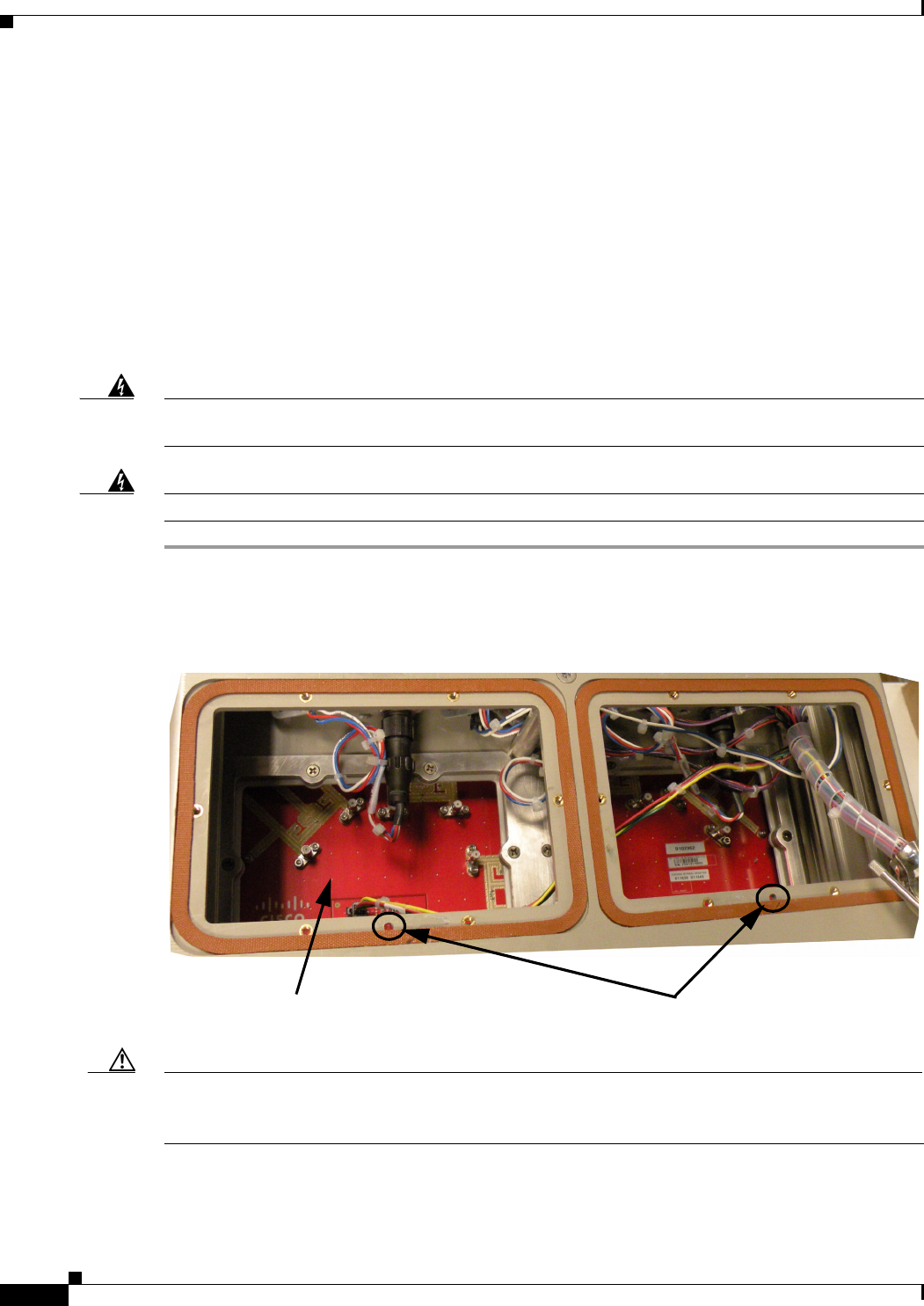
Step 1 Remove the two lower faceplate covers on the back of the AU, to access the RF calibration board and
RF cable connectors. Refer to Figure 6-4.
Figure 6-4 Faceplate Covers Removed
Caution Do not attempt to insert the RU into the AU without removing the lower faceplate covers. These faceplate
covers have a mechanical interlock pin, which inserts into the RU, and if the faceplate covers are not
removed when inserting the RU, damage could occur to the RU and the mechanical interlock pins.
Step 2 Insert the RU into the AU, as shown in Figure 6-5.
RF Calibration Board Mechanical Interlock Pin Holes
PRELIMINARY
6-5
BWX 8415 Basestation Installation and Commissioning Guide
OL-19519-01
Chapter 6 Installation
6.2.3 Install the Radio Unit
Figure 6-5 Inserting the RU into the AU
Step 3 Connect the RF cables and the Cal cable, coming from the RF calibration board, to the RF connectors
and Cal connector on the RU unit.
Step 4 Replace the faceplate covers. Be sure to insert the pin on the faceplate covers into the mechanical
interlock holes on the AU and RU units, these holes should align when the RU is inserted into the AU.
Caution Ensure that the faceplate covers are properly secured to prevent water from leaking into the unit.
Step 5 Install the lower manifold.
Caution Ensure that the lower manifold is properly secured to ensure that the air flow for the heat exchangers is
contained within the unit.
Step 6 Install the I/O cable cover. (It is not necessary to completely tighten these covers at this time. The covers
are being installed to prevent them from swinging while the BWX 8415 Basestation is being hoisted.)
Step 7 Once installed, proceed to the next section of this Guide.
Note To remove the RU, after it has been installed, refer to Appendix F, “Radio Unit Removal”.
PRELIMINARY
6-6
BWX 8415 Basestation Installation and Commissioning Guide
OL-19519-01
Chapter 6 Installation
6.3 BWX 8415 Installation
6.3 BWX 8415 Installation
Reference:
• Appendix A, “Cisco Recommended Tools”
Check all regulatory requirements prior to installing the BWX 8415 Basestation.
Caution - Refer installation and service to qualified service personnel only. No user serviceable parts inside.
- Installation must be done in accordance with the instructions contained in this manual.
- Read these instructions before installing.
- Save these instructions.
6.3.1 Description
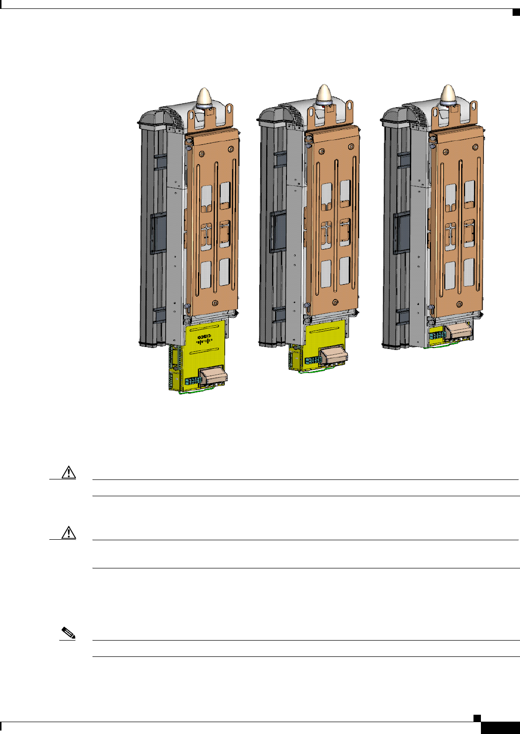
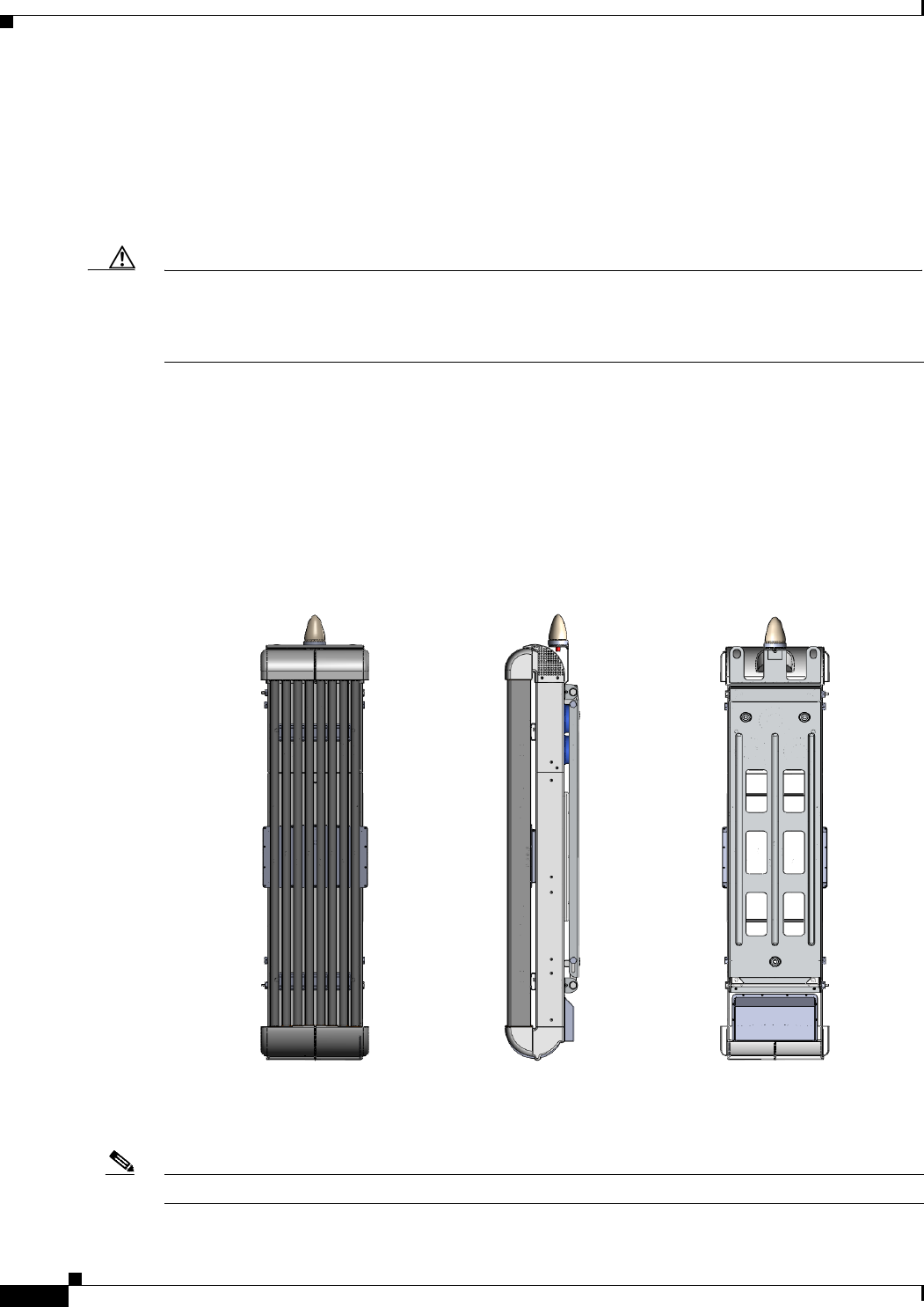
The Antenna Unit (AU) is the part of the BS that contains the eight radiating antenna elements, the heat
exchanger, calibration board, external thermal sensor and optional channel filters. (These filters are
installed on the outside rear of the AU.) An AU (refer to Figure 6-6) radiates over a sector of 90° or 120°,
configured during commissioning.
Figure 6-6 BWX 8415 Antenna Unit
Note The 8 element AU has 6° of fixed electrical downtilt.
Front View Side View Rear ViewFront View Side View Rear View

PRELIMINARY
6-7
BWX 8415 Basestation Installation and Commissioning Guide
OL-19519-01
Chapter 6 Installation
6.3.2 Install the GPS Antenna Cable
6.3.1.1 Channel Filters
In the BWX 8415 Basestation you have the option to:
• 1 - Use a Channel filter:
The functions of Channel filters are two-fold: (1) to shape the power amplifier out-of-band emission
during transmission in order to meet FCC or other regulatory requirements; and (2) to provide high
rejection for close-in jammers during the receive period. The latter improves receiver selectivity. As
indicated by its name, the filter operates in a specific limited frequency band (e.g., Bandwidth (BW)
= 5 to 20 MHz) and has more stringent attenuation requirements. Normally, the attenuation is 15-20
dB rejection for close-in frequencies.
If a BWX 8415 Basestation has channel filters installed, it must be operated at a center frequency
that exactly matches the center frequency for which the channel filters were manufactured;
otherwise, the equipment could be damaged.
• 2 - Not use a filter at all:
If no channel filters are installed, the service provider is free to select or change the center frequency of
the BS without damaging the equipment.
Note Depending on the country where the system is being used, a channel filter may be required to meet the
spectrum requirements of that region. A consideration to keep in mind when addressing a deployment
for a specific region.
If the channel filters do not come installed and you have to install them, please refer to Appendix E,
“BWX 8415 Channel Filter Installation Procedure”, for the procedure to install the filters.
Note If channel filters are required to be installed, after the BWX 8415 Basestation has been installed on the
tower or building, the basestation will need to be lowered to the ground.
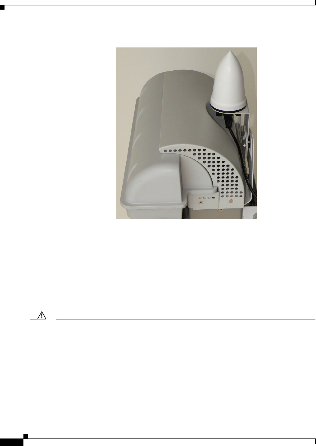
6.3.2 Install the GPS Antenna Cable
Connect the GPS cable to the GPS antenna, located at the top of the BWX 8415 BS and tighten the
connector to 12 to 15 in-lbs. (1.4 to 1.7 Nm). Refer to Figure 6-7.
Note In the event that the BWX 8415 BS is mounted on the side of a building, the GPS antenna can be removed
from the BS and mounted to a location where the antenna will have a clear 360° view of the sky. The
GPS cable loss must be less than 8 dB.
PRELIMINARY
6-8
BWX 8415 Basestation Installation and Commissioning Guide
OL-19519-01
Chapter 6 Installation
6.3.3 Handling the BWX 8415 Basestation
Figure 6-7 GPS Antenna Cable Installed
6.3.3 Handling the BWX 8415 Basestation
It is a good idea to inspect the exterior of the AU for any damage that may have occurred during shipping,
prior to placing it at the target site. Each of the antenna elements in the AU are covered by the individual
radomes on the panel. At all times handle the antenna carefully. If, during storage, filter replacement, or
RU replacement, you must place a panel antenna in a position laying down, make sure it rests flat on at
least one inch of plastic foam to prevent damage to the antenna elements.
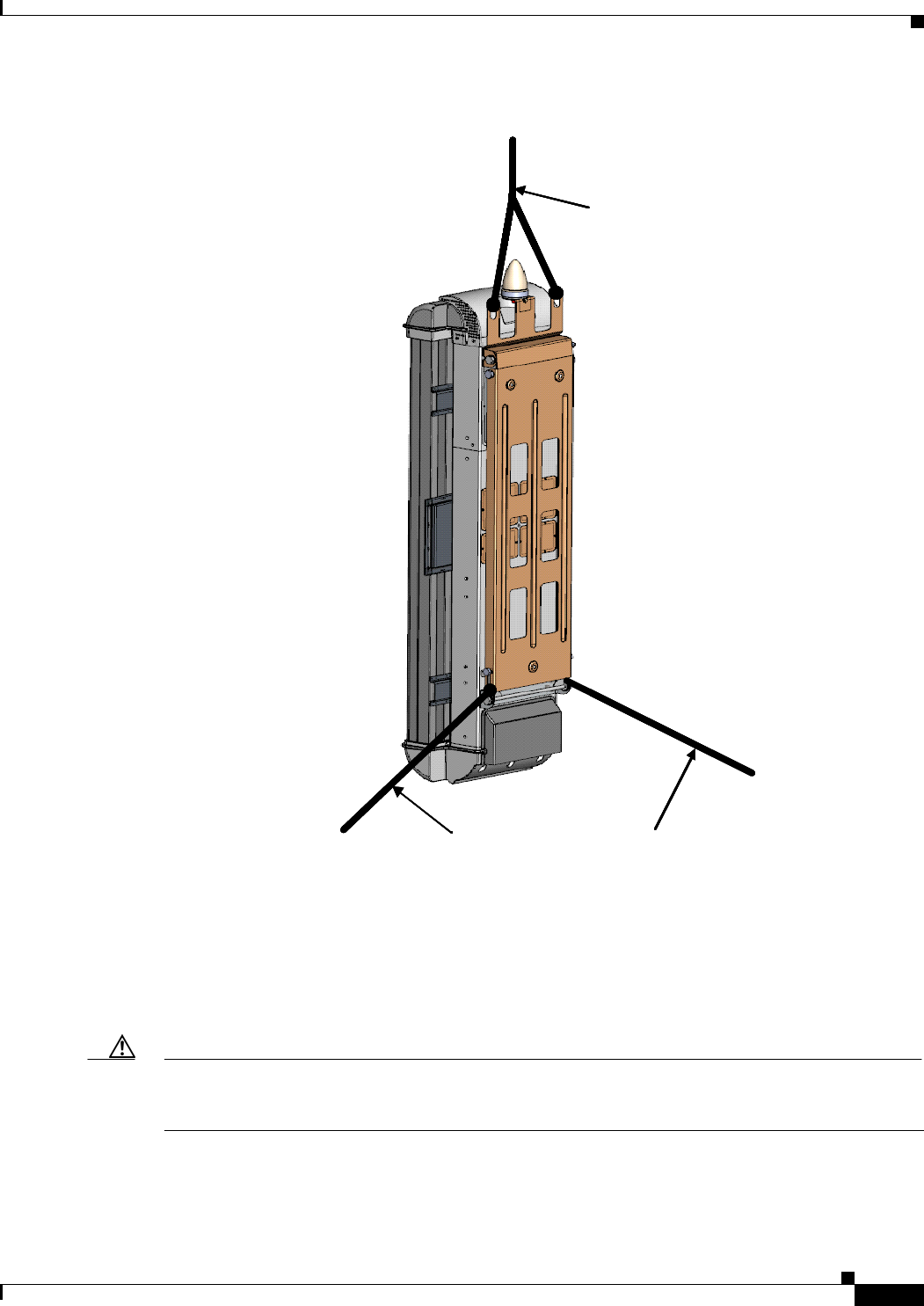
When you are ready to place the antenna into position, it should be lifted using multiple lift points.
Attach the hoisting cable to the AU’s lift points, as shown in Figure 6-8.
Caution Never use the radomes to lift, support, or otherwise bear partial or full weight of the BWX 8415
Basestation. Doing so can cause damage to the radomes.
Use two ground-anchor lines attached to the lower mounting bracket to steer the AU and prevent it from
spinning or swaying in the wind and perhaps hitting the tower or other nearby structures with the
radomes.
PRELIMINARY
6-9
BWX 8415 Basestation Installation and Commissioning Guide
OL-19519-01
Chapter 6 Installation
6.3.4 Mounting the BWX 8415 Basestation
Figure 6-8 Lifting the BWX 8415 Antenna Unit
6.3.4 Mounting the BWX 8415 Basestation
This section provides instructions for installing the BWX 8415 Basestation. The BWX 8415 can be
either pole mounted or wall mounted. The BWX 8415 includes both pole and wall mounting hardware
(with the exception of anchor bolts).
Caution The wall and mounting hardware (anchor bolts) chosen to mount the BS shall be capable of supporting
both the static weight of the BS and the lateral load, resulting from wind loading. All mounting methods
on any wall surface must be in compliance with local building and safety codes.
Hoisting Cable
Ground-anchor Lines
Hoisting Cable
Ground-anchor Lines
PRELIMINARY
6-10
BWX 8415 Basestation Installation and Commissioning Guide
OL-19519-01
Chapter 6 Installation
6.3.4 Mounting the BWX 8415 Basestation
Warning
In order to comply with radio frequency (RF) exposure limits, the antennas for this product should be
positioned no less than 6.56 ft (2 m) from your body or nearby persons.
Statement 339
Warning
Do not work on the system or connect or disconnect cables during periods of lightning activity.
Statement 1001
Warning
Only trained and qualified personnel should be allowed to install, replace, or service this equipment.
Statement 1030
Warning
Installation of the equipment must comply with local and national electrical codes.
Statement 1074
6.3.4.1 Mounting the BWX 8415 on a Wall
When installing the BWX 8415 on an outdoor wall, ensure that the wall and mounting hardware (anchor
bolts) chosen to mount the BS are capable of supporting both the static weight of the BS and the lateral
load, resulting from wind loading and that the installation adheres to all local building and safety codes.
Note The following specifications should be helpful in planning the wall mounted installation:
Dimensions: 2.3 & 2.5 GHz - 62 X 20 X 12 in (158 X 50 X 30 cm)
3.5 GHz - 62 X 14.5 X 12 in (158 X 37 X 30 cm)
Weight: 110 lbs. (50 kg) w/o filters [does not include the external cable strain relief]
Wind Loading: 170 lbs. with 100 mile/h lateral thrust (77 kg with 161 km/h lateral thrust)
Ice Loading: The BS can operate with up to .75 in (1.9 cm) thick buildup of ice without sustaining
damage.
6.3.4.2 Mounting the BWX 8415 on a Pole
When installing the BWX 8415 on a pole, keep in mind that the mounting bracket supports metal, wood,
or fiberglass poles from 3 - 4.5 inches (7.6 - 11.4 cm) in diameter. Figure 6-9 illustrates the mounting
bracket.
PRELIMINARY
6-11
BWX 8415 Basestation Installation and Commissioning Guide
OL-19519-01
Chapter 6 Installation
6.3.4 Mounting the BWX 8415 Basestation
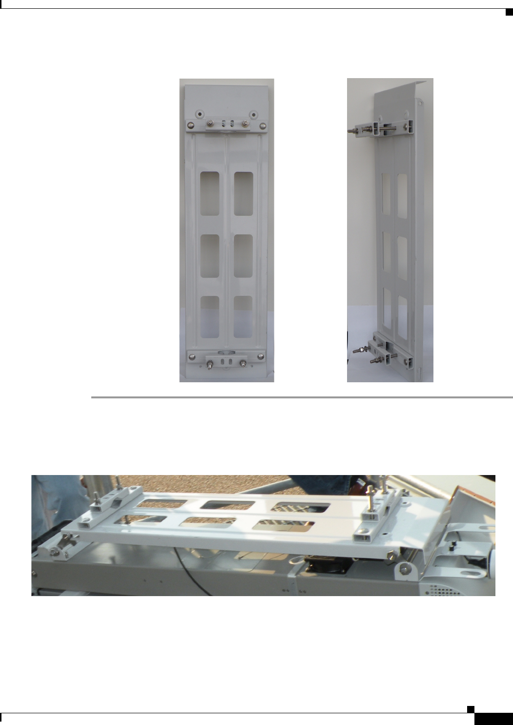
Figure 6-9 BWX 8415 Mounting Bracket
Step 1 Position the mounting bracket on the BWX 8415 and secure the mounting bracket with four bolts, there
are two bolts at the top of the bracket and two bolts at the bottom of the bracket (see Figure 6-10).
Tighten the bolts to 45 ft-lbs. (61 Nm).
Figure 6-10 Mounting Bracket Positioned on BWX 8415
Step 2 Hoist the BWX 8415 onto the tower. Refer to section 6.3.3 Handling the BWX 8415 Basestation for
hoisting requirements.
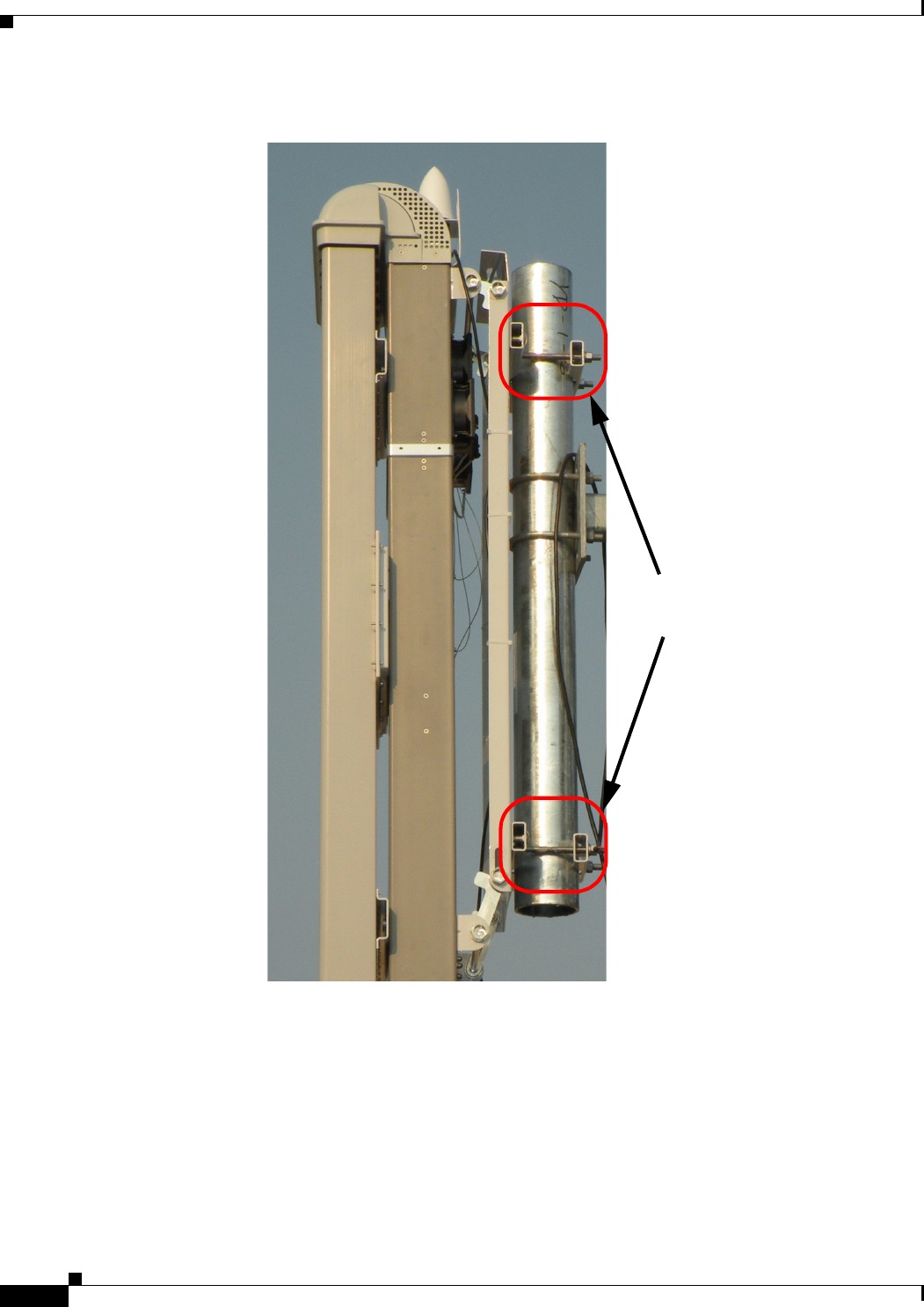
Step 3 Position the BWX 8415 on the pole, on the tower and attach the BWX 8415 to the pole using the
mounting hardware on the mounting bracket. Open the anti-seize compound (supplied), and apply a
liberal amount over the metal surface where the mounting hardware and bracket.
Step 4 Ensure the BWX 8415 is vertical, and tighten the four nuts to 45 ft-lbs. (61 Nm). Refer to Figure 6-11.
PRELIMINARY
6-12
BWX 8415 Basestation Installation and Commissioning Guide
OL-19519-01
Chapter 6 Installation
6.3.5 Antenna Separation
Figure 6-11 BWX 8415 Attached to Pole/Mast
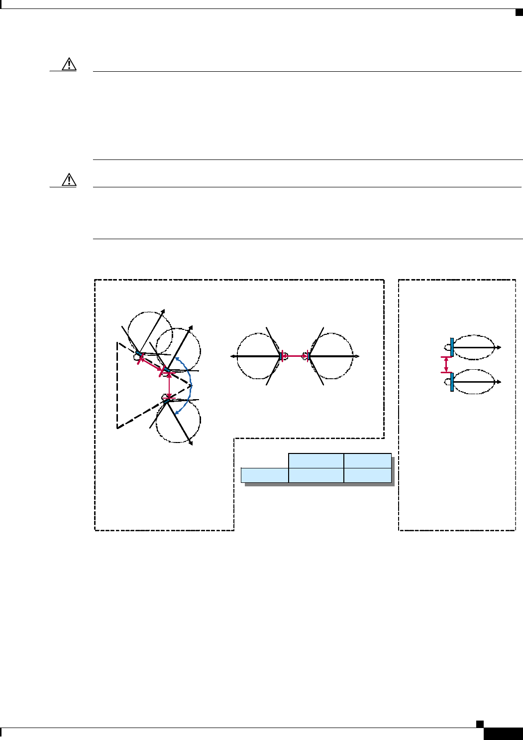
6.3.5 Antenna Separation
When installing multiple BSs in the same geographical area, it is important to allow enough separation
so that they do not interfere with one another. Figure 6-12 provides some general guidelines for avoiding
adjacent interference. The illustration shows the horizontal and vertical separation in feet and in meters
for panel antennas.
Pole/Mast Mounting
Bracket Bolts
PRELIMINARY
6-13
BWX 8415 Basestation Installation and Commissioning Guide
OL-19519-01
Chapter 6 Installation
6.3.5 Antenna Separation
Caution There can be no co-location of MC-SCDMA with Mobile WiMAX basestations. If 2 or more BSs are
co-located on the same structure, they must run the same technology or be upgraded in the same
maintenance window. Use frequency separation to minimize interference between a MC-SCDMA and
Mobile WiMAX basestation. A reasonable frequency separation is 15 MHz for BSs that are 2 kilometers
apart. The exact frequency separation may differ on a case-by-case basis. Therefore, 15 MHz with 2
kilometers between basestations may not provide enough separation. Refer to the BWX Mobile WiMAX
Migration Planning Guide for more information on distance requirements.
Caution All BSs in a network must have the same DL/UL symbol ratio. The default recommended ratio is 32/15.
Cisco does not support basestations that use different DL/UL symbol ratios in the same area because they
will interfere with each other. Please refer to the BWX EMS Configuration Guide for more information
on parameter settings.
Figure 6-12 General Separation Guidelines
HORIZONTAL SEPARATION (TOP VIEW)
PanelPanel PanelPanel PanelPanel 5 ft5 ft5 ft
(1.5 m)(1.5 m)(1.5 m)
Panel
Panel
Panel
Panel
(1.5 m)(1.5 m)
5 ft5 ft5 ft
(1.5 m)
Panel
120°120°120°
VERTICAL SEPARATION
(SIDE VIEW)
Panel
10 ft
(3 m)
Panel
PanelPanel
PanelPanel
Panel-Panel
Horizontal Vertical
5 ft (1.5 m) 10 ft (3 m)
HORIZONTAL SEPARATION (TOP VIEW)
PanelPanel PanelPanel PanelPanel 5 ft5 ft5 ft
(1.5 m)(1.5 m)(1.5 m)
Panel
Panel
Panel
Panel
(1.5 m)(1.5 m)
5 ft5 ft5 ft
(1.5 m)
Panel
120°120°120°
HORIZONTAL SEPARATION (TOP VIEW)
PanelPanel PanelPanel PanelPanel 5 ft5 ft5 ft
(1.5 m)(1.5 m)(1.5 m)
Panel
Panel
Panel
Panel
(1.5 m)(1.5 m)
5 ft5 ft5 ft
(1.5 m)
Panel
120°120°120°
PanelPanel PanelPanel PanelPanel 5 ft5 ft5 ft
(1.5 m)(1.5 m)(1.5 m)
Panel
Panel
Panel
Panel
(1.5 m)(1.5 m)
5 ft5 ft5 ft
(1.5 m)
Panel
120°120°120°
PanelPanel PanelPanel PanelPanel 5 ft5 ft5 ft
(1.5 m)(1.5 m)(1.5 m)
PanelPanel PanelPanel PanelPanel 5 ft5 ft5 ft5 ft5 ft5 ft
(1.5 m)(1.5 m)(1.5 m)(1.5 m)(1.5 m)(1.5 m)
Panel
Panel
Panel
Panel
(1.5 m)(1.5 m)
5 ft5 ft5 ft
(1.5 m)
Panel
120°120°120°
Panel
Panel
Panel
Panel
(1.5 m)(1.5 m)
5 ft5 ft5 ft
(1.5 m)(1.5 m)(1.5 m)
5 ft5 ft5 ft5 ft5 ft5 ft
(1.5 m)
Panel
120°120°120°120°120°120°
VERTICAL SEPARATION
(SIDE VIEW)
Panel
10 ft
(3 m)
Panel
PanelPanel
PanelPanel
VERTICAL SEPARATION
(SIDE VIEW)
Panel
10 ft
(3 m)
Panel
PanelPanel
PanelPanel
VERTICAL SEPARATION
(SIDE VIEW)
Panel
10 ft
(3 m)
Panel
PanelPanel
PanelPanel
Panel
10 ft
(3 m)
Panel
PanelPanel
PanelPanel
Panel-Panel
Horizontal Vertical
5 ft (1.5 m) 10 ft (3 m)
Panel-PanelPanel-Panel
HorizontalHorizontal VerticalVertical
5 ft (1.5 m)5 ft (1.5 m) 10 ft (3 m)10 ft (3 m)
PRELIMINARY
6-14
BWX 8415 Basestation Installation and Commissioning Guide
OL-19519-01
Chapter 6 Installation
6.3.5 Antenna Separation
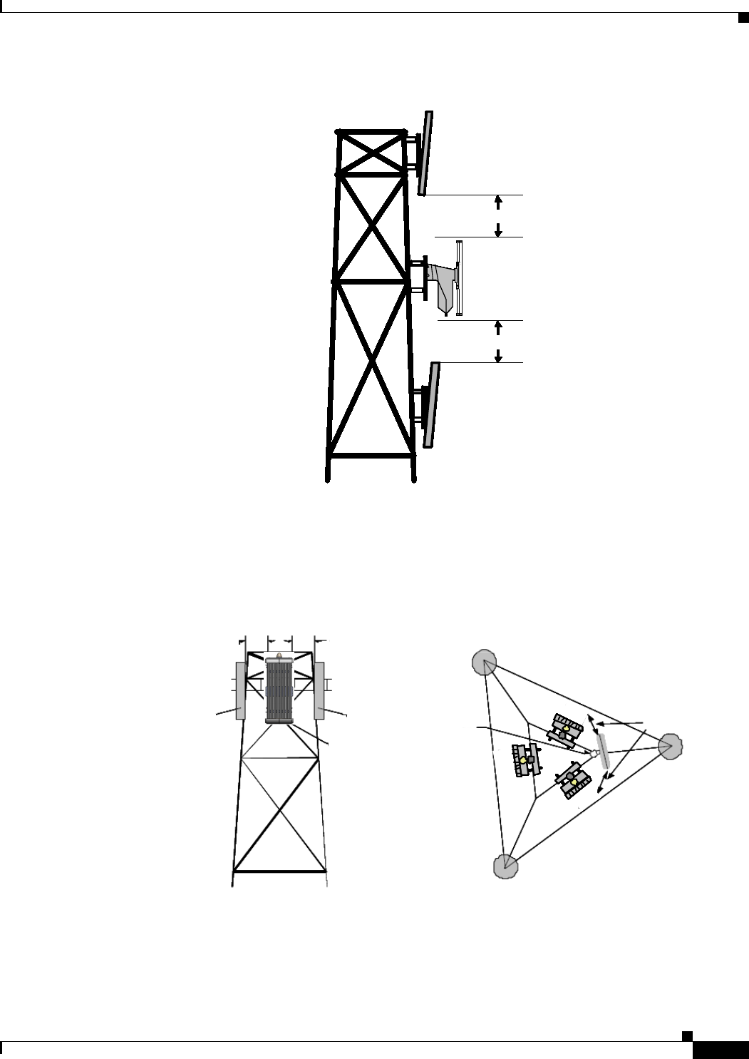
6.3.5.1 Vertical Separation - Cisco to Another Vendor
The minimum vertical separation between any Cisco BWX 8415 BS and another vendor’s antenna is
10 ft. Refer to Figure 6-13.
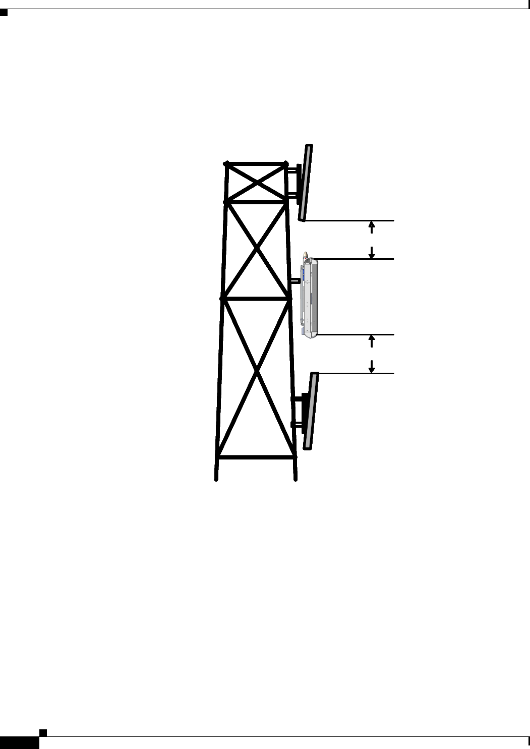
Figure 6-13 Vertical Separation (Cisco BWX 8415 BS to Other Vendor’s Antenna)
6.3.5.2 Vertical Separation – Cisco to Cisco
A minimum of 3 ft separation in the vertical axis is required between the BWX 8415 BS and any Cisco
antennas (Figure 6-14). This separation is needed to obtain proper and optimum results from each
antenna.
10 Ft Separation
10 Ft Separation
Other Vendor’s
Anten na
10 Ft Separation10 Ft Separation
10 Ft Separation10 Ft Separation
Cis co BWX 84 15
Bas est atio n
Cis co BWX 84 15
Bas est atio n
10 Ft Separation
10 Ft Separation
10 Ft Separation10 Ft Separation
10 Ft Separation10 Ft Separation
Cis co BWX 84 15
Bas est atio n
Cis co BWX 84 15
Bas est atio n
Cis co BWX 84 15
Bas est atio n
Cis co BWX 84 15
Bas est atio n
Other Vendor’s
Anten na
10 Ft Separation
10 Ft Separation
Other Vendor’s
Anten na
10 Ft Separation10 Ft Separation
10 Ft Separation10 Ft Separation
Cis co BWX 84 15
Bas est atio n
Cis co BWX 84 15
Bas est atio n
10 Ft Separation
10 Ft Separation
10 Ft Separation10 Ft Separation
10 Ft Separation10 Ft Separation
Cis co BWX 84 15
Bas est atio n
Cis co BWX 84 15
Bas est atio n
Cis co BWX 84 15
Bas est atio n
Cis co BWX 84 15
Bas est atio n
Other Vendor’s
Anten na
PRELIMINARY
6-15
BWX 8415 Basestation Installation and Commissioning Guide
OL-19519-01
Chapter 6 Installation
6.3.5 Antenna Separation
Figure 6-14 Vertical Separation (Cisco BWX 8415 BS to Cisco Antenna)
6.3.5.3 Horizontal Separation – Cisco to Another Vendor
A minimum of 10 ft horizontal separation is required between a Cisco BWX 8415 BS and another
vendor’s antenna (Figure 6-15).
Figure 6-15 Horizontal Separation (Cisco BWX 8415 BS to Another Vendor’s Antenna)
6.3.5.4 Horizontal Separation – Cisco to Cisco
A minimum of 10 ft of separation between a Cisco BWX 8415 BS and any Cisco antennas is required.
10 Ft Separation10 Ft Separation10 Ft Separation10 Ft Separation10 Ft Separation10 Ft Separation10 Ft Separation10 Ft Separation10 Ft Separation10 Ft Separation10 Ft Separation10 Ft Separation
10 Ft Separation10 Ft Separation10 Ft Separation10 Ft Separation10 Ft Separation10 Ft Separation10 Ft Separation10 Ft Separation10 Ft Separation10 Ft Separation10 Ft Separation10 Ft Separation
Cisco BWX 8305
BasestationBasestationBasestationBasestationBasestationBasestationBasestationBasestationBasestationBasestationBasestationBasestation
Cisco Antenna
10 Ft Separation10 Ft Separation10 Ft Separation10 Ft Separation10 Ft Separation10 Ft Separation10 Ft Separation10 Ft Separation10 Ft Separation10 Ft Separation10 Ft Separation10 Ft Separation
10 Ft Separation10 Ft Separation10 Ft Separation10 Ft Separation10 Ft Separation10 Ft Separation10 Ft Separation10 Ft Separation10 Ft Separation10 Ft Separation10 Ft Separation10 Ft Separation
Cisco BWX 8305
BasestationBasestationBasestationBasestationBasestationBasestationBasestationBasestationBasestationBasestationBasestationBasestation
Cisco Antenna
Cisco Antenna
10 Ft Separation10 Ft Separation10 Ft Separation10 Ft Separation10 Ft Separation10 Ft Separation10 Ft Separation10 Ft Separation10 Ft Separation10 Ft Separation10 Ft Separation10 Ft Separation10 Ft Separation10 Ft Separation10 Ft Separation10 Ft Separation10 Ft Separation10 Ft Separation10 Ft Separation10 Ft Separation10 Ft Separation10 Ft Separation10 Ft Separation10 Ft Separation
10 Ft Separation10 Ft Separation10 Ft Separation10 Ft Separation10 Ft Separation10 Ft Separation10 Ft Separation10 Ft Separation10 Ft Separation10 Ft Separation10 Ft Separation10 Ft Separation10 Ft Separation10 Ft Separation10 Ft Separation10 Ft Separation10 Ft Separation10 Ft Separation10 Ft Separation10 Ft Separation10 Ft Separation10 Ft Separation10 Ft Separation10 Ft Separation
Cisco BWX 8305
BasestationBasestationBasestationBasestationBasestationBasestationBasestationBasestationBasestationBasestationBasestationBasestation
Cisco BWX 8305
BasestationBasestationBasestationBasestationBasestationBasestationBasestationBasestationBasestationBasestationBasestationBasestation
Cisco Antenna
10 Ft Separation10 Ft Separation10 Ft Separation10 Ft Separation10 Ft Separation10 Ft Separation10 Ft Separation10 Ft Separation10 Ft Separation10 Ft Separation10 Ft Separation10 Ft Separation
10 Ft Separation10 Ft Separation10 Ft Separation10 Ft Separation10 Ft Separation10 Ft Separation10 Ft Separation10 Ft Separation10 Ft Separation10 Ft Separation10 Ft Separation10 Ft Separation
Cisco BWX 8305
BasestationBasestationBasestationBasestationBasestationBasestationBasestationBasestationBasestationBasestationBasestationBasestation
Cisco Antenna
Cisco AntennaCisco Antenna
10 Ft Separation10 Ft Separation10 Ft Separation10 Ft Separation10 Ft Separation10 Ft Separation10 Ft Separation10 Ft Separation10 Ft Separation10 Ft Separation10 Ft Separation10 Ft Separation10 Ft Separation10 Ft Separation10 Ft Separation10 Ft Separation10 Ft Separation10 Ft Separation10 Ft Separation10 Ft Separation10 Ft Separation10 Ft Separation10 Ft Separation10 Ft Separation
10 Ft Separation10 Ft Separation10 Ft Separation10 Ft Separation10 Ft Separation10 Ft Separation10 Ft Separation10 Ft Separation10 Ft Separation10 Ft Separation10 Ft Separation10 Ft Separation10 Ft Separation10 Ft Separation10 Ft Separation10 Ft Separation10 Ft Separation10 Ft Separation10 Ft Separation10 Ft Separation10 Ft Separation10 Ft Separation10 Ft Separation10 Ft Separation
Cisco BWX 8305
Basestation
10 Ft Separation10 Ft Separation10 Ft Separation10 Ft Separation10 Ft Separation10 Ft Separation10 Ft Separation10 Ft Separation10 Ft Separation10 Ft Separation10 Ft Separation10 Ft Separation10 Ft Separation10 Ft Separation10 Ft Separation10 Ft Separation10 Ft Separation10 Ft Separation10 Ft Separation10 Ft Separation10 Ft Separation10 Ft Separation10 Ft Separation10 Ft Separation
10 Ft Separation10 Ft Separation10 Ft Separation10 Ft Separation10 Ft Separation10 Ft Separation10 Ft Separation10 Ft Separation10 Ft Separation10 Ft Separation10 Ft Separation10 Ft Separation10 Ft Separation10 Ft Separation10 Ft Separation10 Ft Separation10 Ft Separation10 Ft Separation10 Ft Separation10 Ft Separation10 Ft Separation10 Ft Separation10 Ft Separation10 Ft Separation
Cisco BWX 8305
BasestationBasestationBasestationBasestationBasestationBasestationBasestationBasestationBasestationBasestationBasestationBasestation
Cisco BWX 8305
BasestationBasestationBasestationBasestationBasestationBasestationBasestationBasestationBasestationBasestationBasestationBasestation
Cisco Antenna
BasestationBasestationBasestationBasestationBasestationBasestationBasestationBasestationBasestationBasestationBasestation
Cisco BWX 8305
BasestationBasestationBasestationBasestationBasestationBasestationBasestationBasestationBasestationBasestationBasestationBasestation
Cisco Antenna
Cisco BWX 8415
Basestation
Cisco BWX 8415
Basestation
Cisco BWX 8415
Basestation
Other Vendor’s
An t en n a
Other Vendor’s
Antenna
C i sc o BWX 84 15
B as e st ati on
Other Vendor’s
Antenna
10 Ft Separation10 Ft Separation
10 Ft Separation
Cisco BWX 8415
Basestation
Cisco BWX 8415
Basestation
Cisco BWX 8415
Basestation
Other Vendor’s
An t en n a
Other Vendor’s
Antenna
C i sc o BWX 84 15
B as e st ati on
Other Vendor’s
Antenna
10 Ft Separation10 Ft Separation
10 Ft Separation
PRELIMINARY
6-16
BWX 8415 Basestation Installation and Commissioning Guide
OL-19519-01
Chapter 6 Installation
6.3.5 Antenna Separation
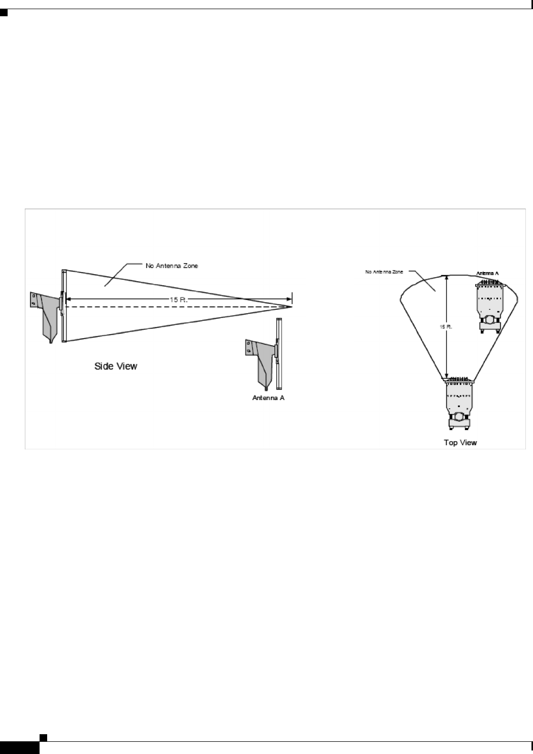
6.3.5.5 No Antenna Zone
If a vertical and horizontal cone extends 15 ft in front of a 120° Panel antenna, this lessens the 10 ft
horizontal and vertical requirements for the placement of the antennas (Figure 6-16). By using these
lesser requirements, the service provider accepts some limitations:
• Signal reflection from the antenna or obstruction
• Shadowing or dead zone in coverage caused by antenna or obstruction
• The amount of reflection and shadowing is affected by the size of the antenna or obstruction
Figure 6-16 No Antenna Zone