Cisco Systems 2484-B8415-R1 WiMAX Base Station, Broadband Wireless, 2.5/2.6 GHz User Manual Installation manual Part 4
Cisco Systems, Inc WiMAX Base Station, Broadband Wireless, 2.5/2.6 GHz Installation manual Part 4
Contents
- 1. Installation manual Part 1
- 2. Installation manual Part 2
- 3. Installation manual Part 3
- 4. Installation manual Part 4
- 5. Installation manual Part 5
Installation manual Part 4

CHAPTER
PRELIMINARY
7-1
BWX 8415 Basestation Installation and Commissioning Guide
OL-19519-01
7
Commissioning
7.1 Install the Element Management System (EMS)
References:
• BWX EMS Overview Manual
• BWX EMS Software Installation Guide
• BWX Mobile WiMAX Configuration Guide
7.1.1 ‘Setup the ‘Test’ EMS
Before installing the EMS software on a local computer, it is a good idea to check the customer’s network
architecture plan. You should review the plan against the actual setup at the site, checking to see that all
equipment and software are installed and available for use. Verify that all routers are installed and IP
addresses are correct.
You will need a “test” EMS computer in order to enter some basic configuration data needed to test the
system once it is powered on. As an installer, you can either use a laptop computer or the customer’s
intended EMS Server. (If you use the customer’s intended EMS Server, it will be connected through the
backhaul, which is a fiber optic connection between the BWX 8415 Basestation (BS) and the service
provider’s network.)
Typically, in order to keep a constant link, a 10/100 Base-T Ethernet hub or switch connects the test EMS
to the BS Data port using an Ethernet cable. This allows the technician to use the EMS Client to
communicate with the EMS Server, which are installed on the same test computer (instructions later in
this chapter).
An RS-232 serial cable is then connected between the test EMS and the Console port on the BS. Using
standard communication software -- i.e., a terminal emulation program, such as Windows HyperTerm or
TeraTerm -- allows the installer to enter basic configuration data at this early stage. The procedure for
setting up the communications software is described below.
PRELIMINARY
7-2
BWX 8415 Basestation Installation and Commissioning Guide
OL-19519-01
Chapter 7 Commissioning
7.1.2 Setting Up Direct Communications Software
7.1.2 Setting Up Direct Communications Software
Step 1 Verify that the fiber optic cable going to the BS is securely connected to the proper port on the backhaul
network.
Step 2 Connect an Ethernet cable between the backhaul network and the Ethernet connector on the PC that will
be used as the test EMS.
Note A VT 100 terminal or any standard Windows-based ASCII terminal emulation program can be
used for connecting to the BS. The connection for HyperTerm is explained here as an illustrative
example. The steps to get to the HyperTerm program may be different due to variances between
Operating Systems and in the PC setup. There have been cases of extra “garbage” data while
using the HyperTerm program. The preferred TeraTerm program can be downloaded free from
the Internet.
Step 3 Power on the test EMS Server.
Step 4 On the PC, go to Start > Programs > Accessories > Communications > HyperTerminal.
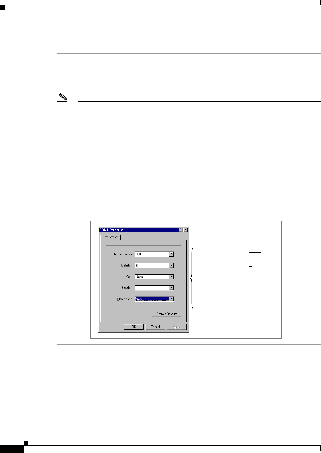
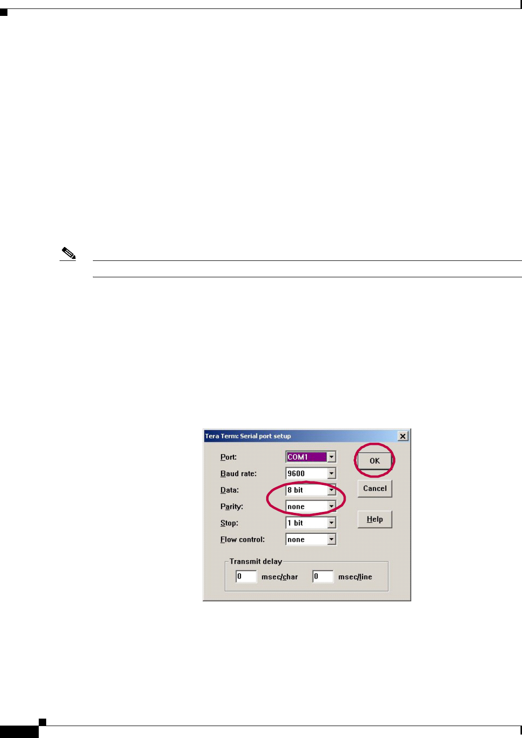
Step 5 In the COM1 Properties window (Figure 7-1), under the Port settings tab enter the configuration options.
Click “OK”.
Figure 7-1 COM1 Properties
Bits per second: 9600
Data Bits: 8
Parity: None
Stop Bits: 1
Flow Control: None
Bits per second: 9600
Data Bits: 8
Parity: None
Stop Bits: 1
Flow Control: None
PRELIMINARY
7-3
BWX 8415 Basestation Installation and Commissioning Guide
OL-19519-01
Chapter 7 Commissioning
7.1.3 Install the BWX EMS Software and Start & Configure the BWX EMS Server
7.1.3 Install the BWX EMS Software and Start & Configure the BWX EMS
Server
7.1.3.1 Install the BWX EMS Software
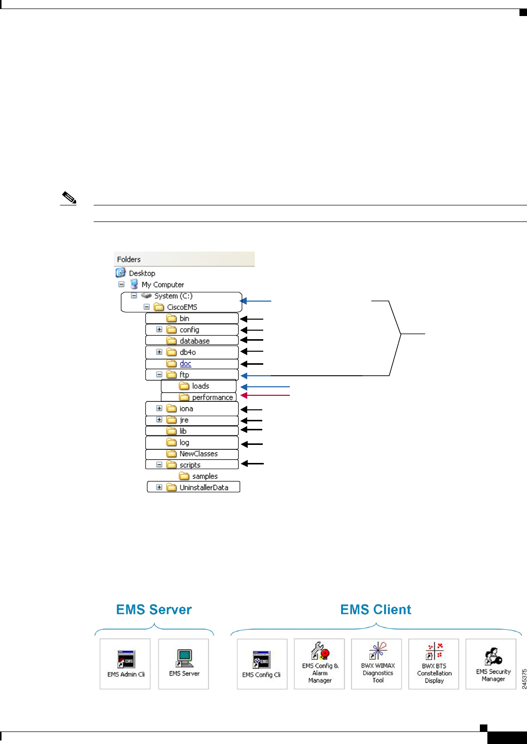
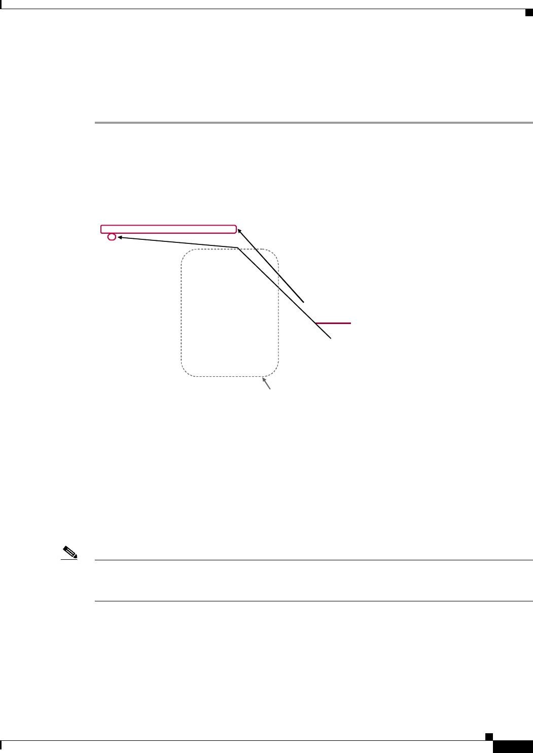
Please refer to the BWX EMS Software Installation Guide for minimum computing requirements and
instructions to load the software. When you load the EMS software into the CiscoEMS\ directory on the
computer, the file structure will look something like what is shown in Figure 7-2. This is a Windows
example.
Note This is the directory when you install the Server. The directory when you install the Client is different.
Figure 7-2 BWX EMS Server Software Directory (in a Windows PC)
Be sure to select the correct instructions for your server – based on operating system, either Windows®
or Unix®. You will need to install both the Server and Client applications (Figure 7-3). Be sure to check
the latest software Release Notes for updated information and procedures for the version of software you
are loading.
Figure 7-3 BWX EMS Server & Client Applications
<EMS Install Directory>
<Ftp Server Root Path>
<BTS/CPE SW Ftp Directory> sw<BTS/CPE SW Ftp Directory> sw load files should be placed here
<Perf Log Storage Directory>
<Perf Log Storage Directory>
online documentationonline documentation
log files are stored herelog files are stored here
script files for CLI should be placed herescript files for CLI should be placed here
databasedatabase
configuration filesconfiguration files
executable filesexecutable files
database-related Java archive (jar) filesdatabase-related Java archive (jar) files
Corba-related filesCorba-related files
Java runtime filesJava runtime files
EMS jar filesEMS jar files
<EMS Install Directory>
<Ftp Server Root Path>
<BTS/CPE SW Ftp Directory> sw<BTS/CPE SW Ftp Directory> sw load files should be placed here<BTS/CPE SW Ftp Directory> sw<BTS/CPE SW Ftp Directory> sw load files should be placed here
<Perf Log Storage Directory>
<Perf Log Storage Directory><Perf Log Storage Directory><Perf Log Storage Directory>
online documentationonline documentationonline documentationonline documentation
log files are stored herelog files are stored herelog files are stored herelog files are stored here
script files for CLI should be placed herescript files for CLI should be placed herescript files for CLI should be placed herescript files for CLI should be placed here
databasedatabasedatabasedatabase
configuration filesconfiguration filesconfiguration filesconfiguration files
executable filesexecutable filesexecutable filesexecutable files
database-related Java archive (jar) filesdatabase-related Java archive (jar) filesdatabase-related Java archive (jar) filesdatabase-related Java archive (jar) files
Corba-related filesCorba-related filesCorba-related filesCorba-related files
Java runtime filesJava runtime filesJava runtime filesJava runtime files
EMS jar filesEMS jar filesEMS jar filesEMS jar files

PRELIMINARY
7-4
BWX 8415 Basestation Installation and Commissioning Guide
OL-19519-01
Chapter 7 Commissioning
7.1.3 Install the BWX EMS Software and Start & Configure the BWX EMS Server
7.1.3.2 Start the BWX EMS Server
This section assumes that the EMS Server & Client applications have already been loaded. The EMS
software installation was described in the previous section. Please refer to the BWX EMS Software
Installation Guide for detailed instructions on starting the EMS server. The default user name and
password are “emsAdmin” (case sensitive). Cisco recommends always changing the default password.
Verify the new password requirement with the customer. After the software files have successfully
loaded, start the EMS Server by performing the following steps:
Step 1 BEFORE starting the EMS Server, open the EMS Admin CLI application and type
enable. After enable is entered, you are prompted for a password. The default password is
“emsAdmin.” The password will be invisible as you type it.
Next, type migratedb. Once the message stating “Database migration succeeded” displays,
exit EMS Admin CLI.
Note If the migration step is run again, you will see the following message: “No Migration Needed, Database
and Application Versions are both 208.”
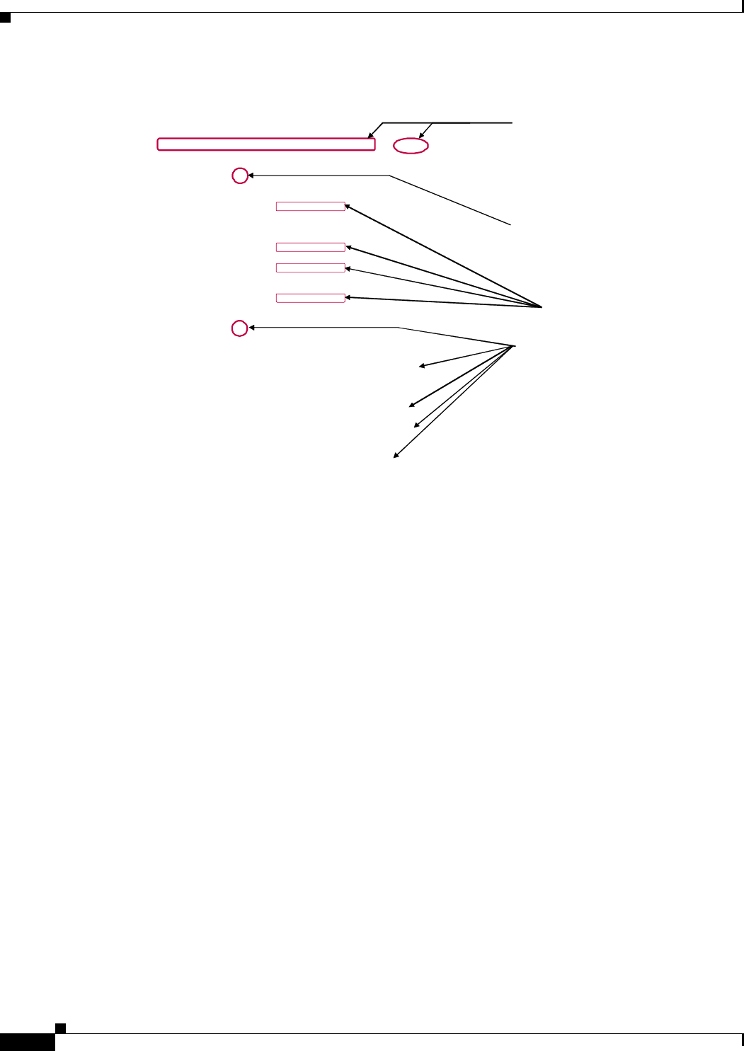
Step 2 On the test EMS Server, double-click on the EMS Server icon to start the EMS Server
application. Allow time for the EMS Server startup procedure to execute. Look for
“EMS Server: UP” to scroll by in the EMS Server window to confirm that the Server is up
and running. If the EMS Server does not start, call Cisco TAC (1-800-553-2447).
The resulting EMS Server window must remain open to keep the EMS Server running. It
can be minimized during Server operation.
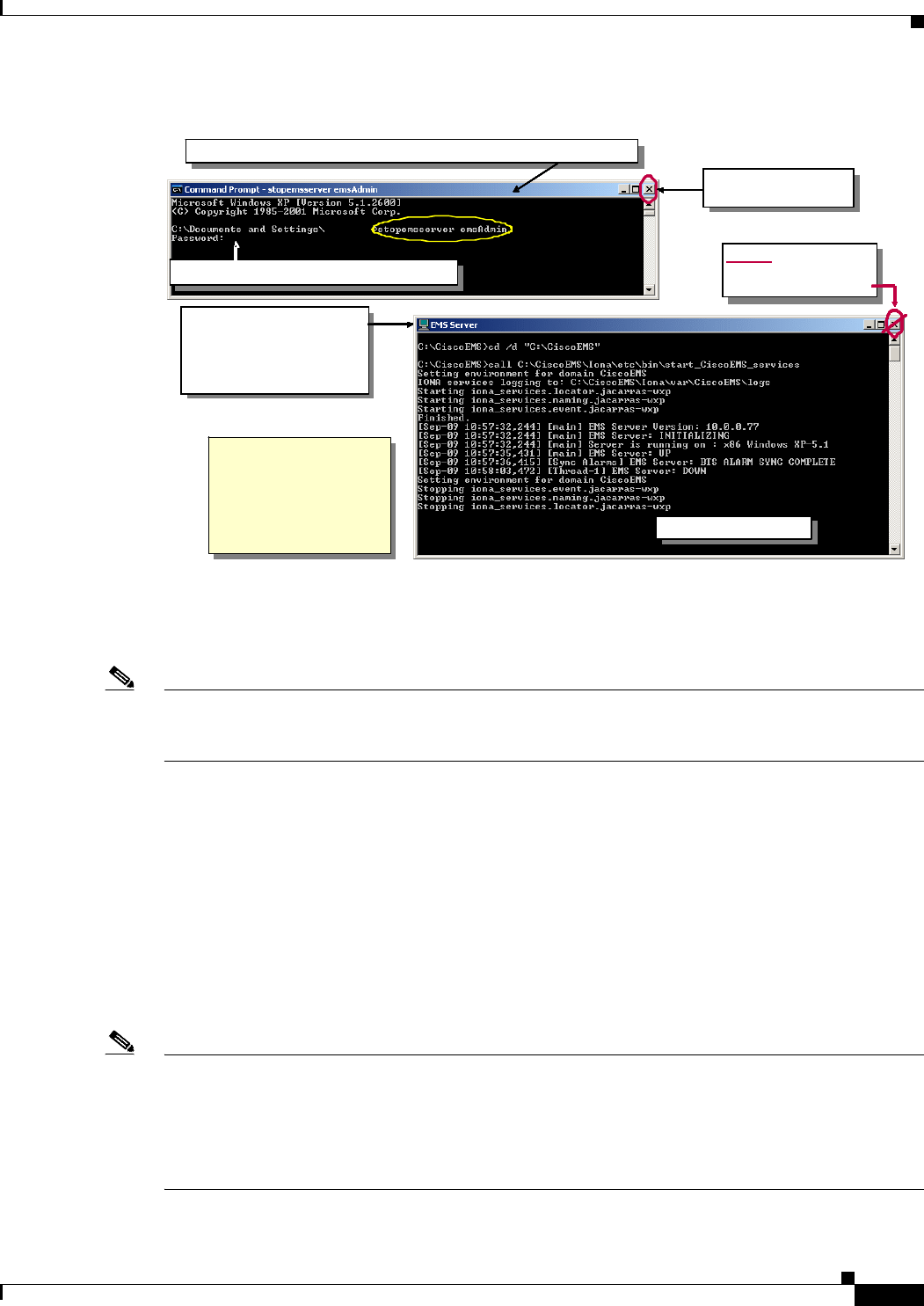
Warning
Note that the EMS Server window should not be closed during Server operations, but it can be
minimized. If the EMS Server ever needs to be stopped, do not click on the “X” in the top right-hand
corner of the window. Instead, open a command prompt window, enter the “
stopemsserver
” command
followed by the administrator user id,
Enter
and then enter the password and
Enter
, as shown in
Figure 7-4.
PRELIMINARY
7-5
BWX 8415 Basestation Installation and Commissioning Guide
OL-19519-01
Chapter 7 Commissioning
7.1.3 Install the BWX EMS Software and Start & Configure the BWX EMS Server
Figure 7-4 Stopping the EMS Server
7.1.3.3 Configure the BWX EMS Server
Note The minimum configuration that you will enter into the EMS server will be through the Configuration
& Alarm Manager (CAM) application, which is a graphical user interface (GUI). If you are not already
familiar with the CAM, please review the BWX Mobile WiMAX Configuration Guide.
Please refer to the BWX Mobile WiMAX Configuration Guide for instructions on the configuration of the
EMS server. The configuration of the EMS server includes the following elements:
• General configuration
• Alarm Management configuration
• Performance Management configuration
7.1.3.3.1 General Configuration
General configuration of the EMS server includes changing the EMS ID & Network ID fields, entering
the FTP user name, password & FTP server root path, and entering the BTS/CPE SW Directory.
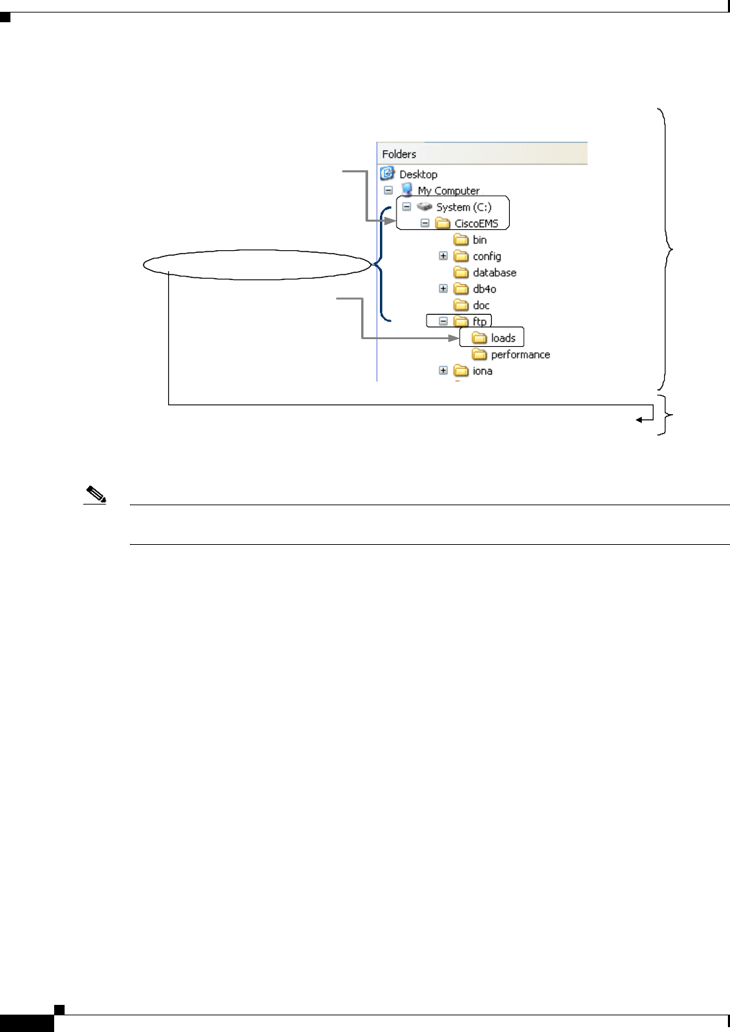
Note The software upgrade files for BSs and Subscriber Stations (SSs) must be stored on the same PC where
the EMS Server was installed. An FTP server must also be installed on that same PC. Under the FTP
server you must add a user, give this user a password, and assign this user a root default directory. Under
the EMS tab, this user, password, and root directory must be specified during configuration. To do an
upgrade, the file(s) are placed on that directory, and the process is initiated on the EMS, which
communicates with the FTP server (which is the one that does the actual transfer). Refer to Figure 7-5.
If this does not work, then
Enter <CTRL>C at the EMS
Server window to Stop the
EMS. When asked if you
want to terminate the batch
file, enter “N” to gracefully
stop all the other processes
3. Allow time for the EMS
shutdown process to
execute. When the process
is com pleted, this window
will close by itself
NEVER CLOSE THE
EMS WINDOW BY
CLICKING ON THE “X” "
"
4. The window closes
4. The window closes
4. The window closes
4. The window closes
ciscolaptop
2. When prompted, enter <adminPassword>
1. Open a Command Prompt window and enter stopemsserver <adminID>
5. Close the Command
prompt window
If this does not work, then
Enter <CTRL>C at the EMS
Server window to Stop the
EMS. When asked if you
want to terminate the batch
file, enter “N” to gracefully
stop all the other processes
3. Allow time for the EMS
shutdown process to
execute. When the process
is com pleted, this window
will close by itself
NEVER CLOSE THE
EMS WINDOW BY
CLICKING ON THE “X” "
"
4. The window closes
4. The window closes
4. The window closes
4. The window closes
If this does not work, then
Enter <CTRL>C at the EMS
Server window to Stop the
EMS. When asked if you
want to terminate the batch
file, enter “N” to gracefully
stop all the other processes
If this does not work, then
Enter <CTRL>C at the EMS
Server window to Stop the
EMS. When asked if you
want to terminate the batch
file, enter “N” to gracefully
stop all the other processes
3. Allow time for the EMS
shutdown process to
execute. When the process
is com pleted, this window
will close by itself
NEVER CLOSE THE
EMS WINDOW BY
CLICKING ON THE “X” "
"
4. The window closes
4. The window closes
4. The window closes
4. The window closes
3. Allow time for the EMS
shutdown process to
execute. When the process
is com pleted, this window
will close by itself
3. Allow time for the EMS
shutdown process to
execute. When the process
is com pleted, this window
will close by itself
3. Allow time for the EMS
shutdown process to
execute. When the process
is com pleted, this window
will close by itself
NEVER CLOSE THE
EMS WINDOW BY
CLICKING ON THE “X” "
"
4. The window closes
4. The window closes
4. The window closes
4. The window closes
NEVER CLOSE THE
EMS WINDOW BY
CLICKING ON THE “X” "
"
NEVER CLOSE THE
EMS WINDOW BY
CLICKING ON THE “X”
NEVER CLOSE THE
EMS WINDOW BY
CLICKING ON THE “X” "
"""
4. The window closes
4. The window closes
4. The window closes
4. The window closes
4. The window closes
4. The window closes
4. The window closes
4. The window closes
ciscolaptop
2. When prompted, enter <adminPassword>
1. Open a Command Prompt window and enter stopemsserver <adminID>
5. Close the Command
prompt window
ciscolaptop
2. When prompted, enter <adminPassword>
ciscolaptopciscolaptopciscolaptop
2. When prompted, enter <adminPassword>2. When prompted, enter <adminPassword>
1. Open a Command Prompt window and enter stopemsserver <adminID>1. Open a Command Prompt window and enter stopemsserver <adminID>1. Open a Command Prompt window and enter stopemsserver <adminID>
5. Close the Command
prompt window
5. Close the Command
prompt window
5. Close the Command
prompt window
PRELIMINARY
7-6
BWX 8415 Basestation Installation and Commissioning Guide
OL-19519-01
Chapter 7 Commissioning
7.2 Install Access Services Network Gateway (ASN-GW) Hardware and Broadband Wireless Gateway (BWG)
Figure 7-5 FTP Server Windows Example
Note If upgrading the EMS software from release 6.2.X to release 7.0 or higher, it will be necessary to
manually change the Ftp Server Root Path field in the Config EMS screen to “C:\CiscoEMS\ftp”.
7.1.3.3.2 Alarm Management Configuration
Alarm Management configuration of the EMS server includes setting the Alarm Auto Acknowledgement
(Alarm AutoAck) parameter, setting the Maximum Acknowledgements per hour (Max Ack Per Hour)
parameter, and setting up the Alarm Notification by Email parameters (Mail server IP, Email addresses,
& specifying which alarms will be mailed to which addresses).
7.1.3.3.3 Performance Management Configuration
Performance Management configuration of the EMS server includes setting the Enable Performance
Analyzer (Enable PerfAnalyzer) parameter, setting up the Alarm Notification by Email parameters (Mail
server IP, & Email addresses) and setting up the SS Auto Logging parameters.
7.2 Install Access Services Network Gateway (ASN-GW)
Hardware and Broadband Wireless Gateway (BWG) Software
The BWX 8415 Basestation interfaces a 7600 Series Access Services Network Gateway (ASN-GW)
router (refer to Figure 7-6). The router must be installed, and then loaded with the WiMAX software
application called Broadband Wireless Gateway (BWG). It is beyond the scope of this document to
provide router installation procedures. For information on installing the Cisco BWG, refer to the
ASN-GW documentation at the following links:
<EMS Install Directory>: C:\CiscoEMS
<Ftp Server Root Path>: C:\CiscoEMS\ft p
<BTS CPE SW Directory>: loads
<BTS CPE SW Ftp User Name>: ems
<BTS CPE SW Ftp Password>: ems
FTP --> Add User --> User Name: ems, Password: ems, Default Directory: C:\CiscoEMS\ftp FTP
EMS
<EMS Install Directory>: C:\CiscoEMS
<Ftp Server Root Path>: C:\CiscoEMS\ft p
<BTS CPE SW Directory>: loads
<BTS CPE SW Ftp User Name>: ems
<BTS CPE SW Ftp Password>: ems
FTP --> Add User --> User Name: ems, Password: ems, Default Directory: C:\CiscoEMS\ftp FTP
EMS
PRELIMINARY
7-7
BWX 8415 Basestation Installation and Commissioning Guide
OL-19519-01
Chapter 7 Commissioning
7.3 Add and Configure the BWG to the EMS Server
www.cisco.com > Documentation > Routers > Cisco 7300 Series Routers or Cisco 7600 Series Routers
or
http://www.cisco.com/en/US/products/hw/routers/ps352/tsd_products_support_series_home.html
or
http://www.cisco.com/en/US/products/hw/routers/ps368/tsd_products_support_series_home.html
or BWG Data Sheet:
http://wwwin.cisco.com/sptg/mscbu/mwg/prods/cmx/pg/bwg/files/BWG-R11-DS.pdf
In section 7.3 are the configuration settings to make the BS and BWG communicate.
Figure 7-6
7600 ASN-GW Routers
7.3 Add and Configure the BWG to the EMS Server
Reference:
• BWX Mobile WiMAX Configuration Guide P/N: OL-16313-02
Please refer to the BWX Mobile WiMAX Configuration Guide for instructions on the configuration of the
BWG. The configuration of the BWG includes the following elements:
The EMS configures in the BWG all information relative to service level agreements (service flows,
packet classifiers, quality of service, user groups, VRFs, etc.) and the definition of AAA services. EMS
initiated BWG configuration is only written into memory. To make configurations non-volatile, they
must be saved with the BWG Action command “Commit to BWG”.
The EMS does not configure Layer 3 information, such as physical and logical interfaces, and routing.
These must be configured manually in the BWG.
7600
PRELIMINARY
7-8
BWX 8415 Basestation Installation and Commissioning Guide
OL-19519-01
Chapter 7 Commissioning
7.4 Authentication, Authorization, and Accounting (AAA) Server Installation
7.4 Authentication, Authorization, and Accounting (AAA) Server
Installation
As part of the WiMAX Profile C architecture, the AAA server is a key element providing subscriber and
device authentication as well as configuration. The BWG communicates using RADIUS with the AAA
server for subscriber/device authentication and configuration. The configuration information is then
relayed by the BWG to the BS using the R6 interface.
Cisco’s BWG open architecture design makes it compatible with any AAA server that also uses open
architecture protocols. In Release 10.0, all subscriber configuration information is captured in an
AAA database.
As a subscriber attempts to access the network, the SS communicates with the BS. The BS contacts the
BWG which in turn interfaces with the AAA database to check authentication and authorization and to
acquire the subscriber’s profile. Assuming the subscriber’s data exists and the subscriber is approved for
network access, the BWG sends the information to the BS to provide service to the subscriber.
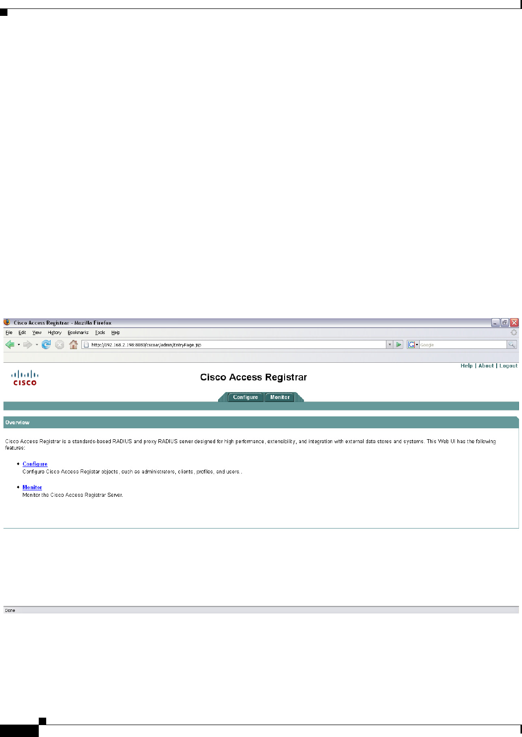
Cisco offers its own AAA application called the Cisco Access Registrar, or CAR, as part of the WiMAX
end-to-end solution (Figure 7-7).
Figure 7-7 Cisco Access Registrar

PRELIMINARY
7-9
BWX 8415 Basestation Installation and Commissioning Guide
OL-19519-01
Chapter 7 Commissioning
7.5 Add and Configure a BWX 8415 Basestation
For information on installing the CAR, refer to the following links:
www.cisco.com > Documentation > Network Management > Security and Identity Management > Cisco
Access Registrar
or
http://www.cisco.com/en/US/products/sw/netmgtsw/ps411/tsd_products_support_series_home.html
Note These sites provide documentation such as Release Notes, Installation and Configuration Guides, and
User Guides.
Note Please note that each vendor’s AAA has its own interface for configuring the subscriber information.
When troubleshooting WiMAX subscriber issues, the service provider will need to investigate both the
EMS and AAA data.
7.5 Add and Configure a BWX 8415 Basestation
7.5.1 Minimum System Configuration Requirements
During deployment of a system, only the minimum EMS, BS, SS, BWG, and global parameters must be
entered to get the system up and running for testing before turning the site over to the service provider.
The service provider may ask you to do more, but in this section we go over the EMS fields that must be
configured in order to complete the commissioning of the system.
At this stage, you should have already installed the EMS Server and Client applications, rebooted the
Server computer (which executed the “configserver” batch file), and added the BWG. The following list
is typical information you will need to know to enter the minimum configuration data.
• Network ID – This is a unique identifier for a given service provider’s network. No other service
provider will have the same Network ID (NID). The NID is provided by Cisco.
• BTS ID – Each BS must have a unique number identifier. The ID must be numeric characters and
be in the following range: 0 - 1048575.
• BTS Name – Each BS must have a unique name identifier. The name can be a mix of alpha and
numeric characters. Cisco recommends entering BWX or another identifier so that other personnel
will later be able to recognize this BS as a BWX system.
• BTS IP Address – When you enter the IP address for the BS, the system will automatically create
a second IP address for that BWX 8415 Basestation. For example, if you enter 10.10.10.1, the EMS
software generates the second IP address as 10.10.10.2. The initial IP address is usually obtained
from the service provider’s network administrator.
• EMS Server IP Address – Obtained from the service provider’s network administrator (for testing
purposes, use the IP address of the PC where the Test EMS resides)
• BTS Subnet Mask – Obtained from the service provider’s network administrator
• BTS Gateway IP Address – Obtained from the service provider’s network administrator
• BTS Center Frequency – Obtained from the RF Plan
• Basestation Antenna Power, RX Sensitivity – determined by Specifications.
PRELIMINARY
7-10
BWX 8415 Basestation Installation and Commissioning Guide
OL-19519-01
Chapter 7 Commissioning
7.5.2 Add a BWX 8415 Basestation
• Active or Passive – Antenna identified
• Antenna Weight (W0) Values – Obtained from the flash drive in the BS
• Whenever you define a new element (BS or SS) in the EMS database, you first add the element, then
configure it by completing various fields through the EMS CAM application. Please refer to the
Cisco OS Release Notes and the BWX Mobile WiMAX Configuration Guide for more datafill
information.
7.5.2 Add a BWX 8415 Basestation
The steps to add a BS are shown in Figure 7-8 through Figure 7-13. Please refer to these figures as you
read the remainder of this section.
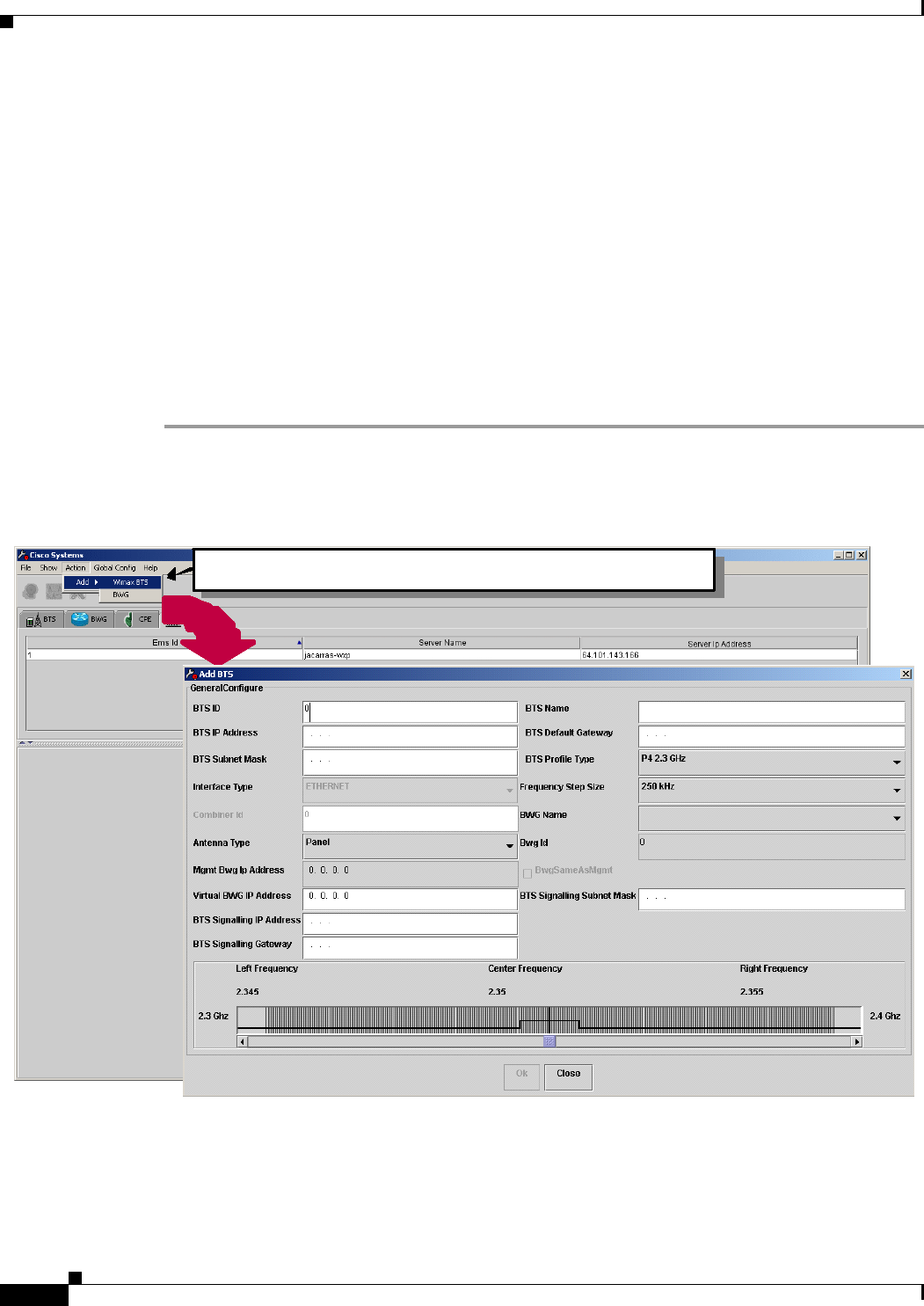
Step 1 To add a BS, use the pull-down menu called Action, select Add > BTS, and then WiMAX. Enter the
information in each field. All of these fields must be entered or accept the defaults.
Figure 7-8 Add Screen for BWX 8415 Basestation
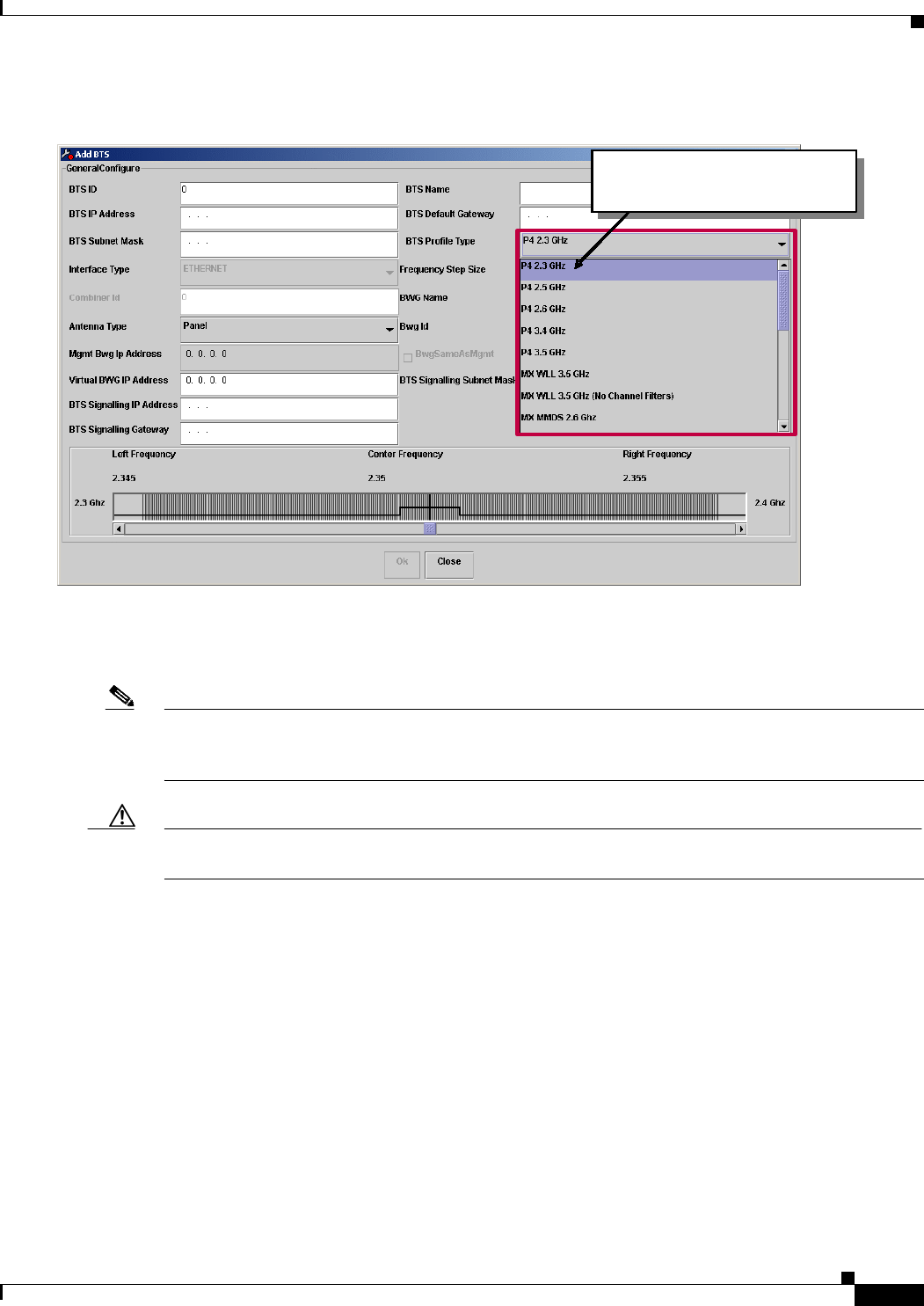
Step 2 Select the frequency band for the BS.
To add a BTS, select: Action > Add > Wimax BTS To add a BTS, select: Action > Add > Wimax BTS To add a BTS, select: Action > Add > Wimax BTS To add a BTS, select: Action > Add > Wimax BTS
PRELIMINARY
7-11
BWX 8415 Basestation Installation and Commissioning Guide
OL-19519-01
Chapter 7 Commissioning
7.5.2 Add a BWX 8415 Basestation
Figure 7-9 Selecting the Frequency Band
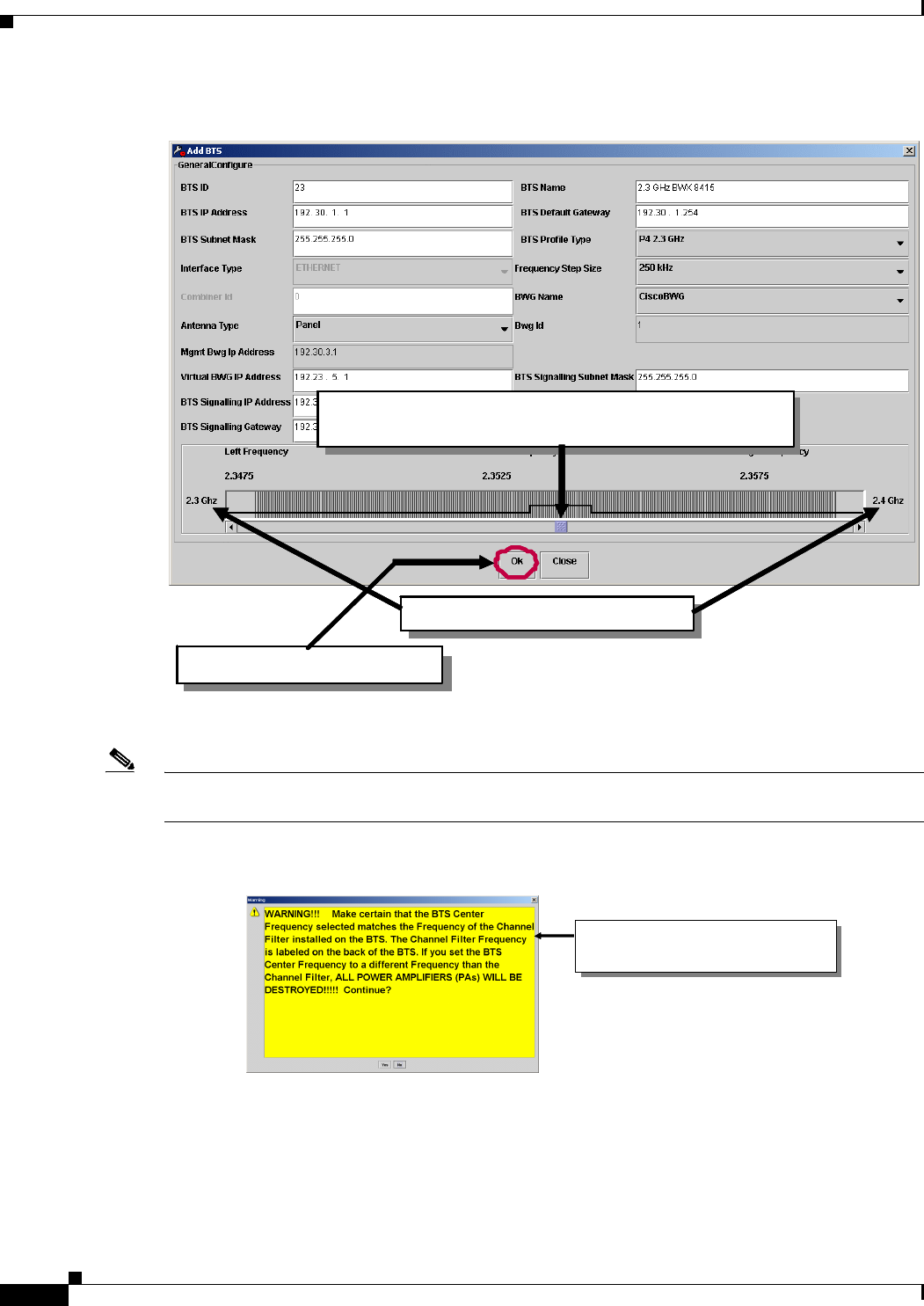
Step 3 Set the center frequency per the service provider’s RF Engineering specifications. This will depend upon
the particular spectrum that the service provider has permission to use, and on other radiating equipment
in the geographical area. The Center Frequency setting is selected using the scroll bar.
Note If this BS will be operating in a licensed band, be sure to check to see whether or not it utilizes Channel
Filters. If it does, the center frequency information must be entered exactly as provided on the sticker on
the BS.
Caution Not entering the exact center frequency specified when using Channel Filters may result in destroying
the Power Amplifiers (PA).
Use this pull-down menu to
select the f requency band.
Use this pull-down menu to
select the f requency band.
Use this pull-down menu to
select the f requency band.
Use this pull-down menu to
select the f requency band.
PRELIMINARY
7-12
BWX 8415 Basestation Installation and Commissioning Guide
OL-19519-01
Chapter 7 Commissioning
7.5.2 Add a BWX 8415 Basestation
Figure 7-10 Setting the Center Frequency
Step 4 Verify that Center Frequency matches the frequency of the Channel Filter and then click Ye s to continue.
Note The EMS gives this warning when you click “OK” to continue configuring the BS after setting the center
frequency.
Figure 7-11 Channel Filter Warning
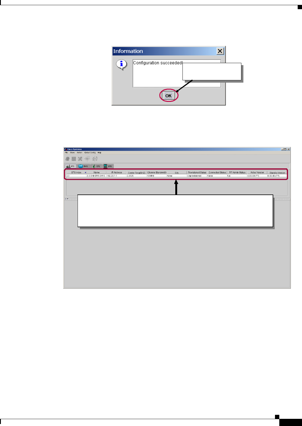
Step 5 Confirm that the BS was added successfully by clicking on Ok.
Adj ust the center frequency by mo ving the blue bar to
the appropriate frequency.
Frequency Range for thi s band
Click on “Ok” to continue.
Adj ust the center frequency by mo ving the blue bar to
the appropriate frequency.
Adj ust the center frequency by mo ving the blue bar to
the appropriate frequency.
Adj ust the center frequency by mo ving the blue bar to
the appropriate frequency.
Frequency Range for thi s bandFr equency Range for thi s bandFr equency Range for thi s band
Click on “Ok” to continue.Click on “Ok” to continue.Click on “Ok” to continue.
This warning is displayed when you are
adding a Basestation that has a Channel
Filter.
This warning is displayed when you are
adding a Basestation that has a Channel
Filter.
This warning is displayed when you are
adding a Basestation that has a Channel
Filter.
This warning is displayed when you are
adding a Basestation that has a Channel
Filter.
PRELIMINARY
7-13
BWX 8415 Basestation Installation and Commissioning Guide
OL-19519-01
Chapter 7 Commissioning
7.5.3 Configure a BWX 8415 Basestation
Figure 7-12 Basestation Added Successfully
Step 6 Next, you will see the new BS added to the list under the BTS tab. Double-click on the BTS entry to
select the BS.
Figure 7-13 Basestation added to the BTS tab
7.5.3 Configure a BWX 8415 Basestation
Configuring the BS consists of setting the following sets of parameters: General, GPS, Layer 1, Layer
2, R6, and CAC.
7.5.3.1 Set the General Parameters
The steps to set the General parameters are shown in Figure 7-14 through Figure 7-19. Please refer to
these figures as you read the remainder of this section.
Click on "Ok" to
continue
Click on "Ok" to
continue
Click on "Ok" to
continue
Click on "Ok" to
continue
The new BWX 8415 basestation appears in the Element ID List area.
Notice that the BTS is “Unprovisioned”. Notice also that the version
number of the current software load is not known at this time. To select
the BTS, double-click anywhere on its line of information.
The new BWX 8415 basestation appears in the Element ID List area.
Notice that the BTS is “Unprovisioned”. Notice also that the version
number of the current software load is not known at this time. To select
the BTS, double-click anywhere on its line of information.
The new BWX 8415 basestation appears in the Element ID List area.
Notice that the BTS is “Unprovisioned”. Notice also that the version
number of the current software load is not known at this time. To select
the BTS, double-click anywhere on its line of information.
The new BWX 8415 basestation appears in the Element ID List area.
Notice that the BTS is “Unprovisioned”. Notice also that the version
number of the current software load is not known at this time. To select
the BTS, double-click anywhere on its line of information.
PRELIMINARY
7-14
BWX 8415 Basestation Installation and Commissioning Guide
OL-19519-01
Chapter 7 Commissioning
7.5.3 Configure a BWX 8415 Basestation
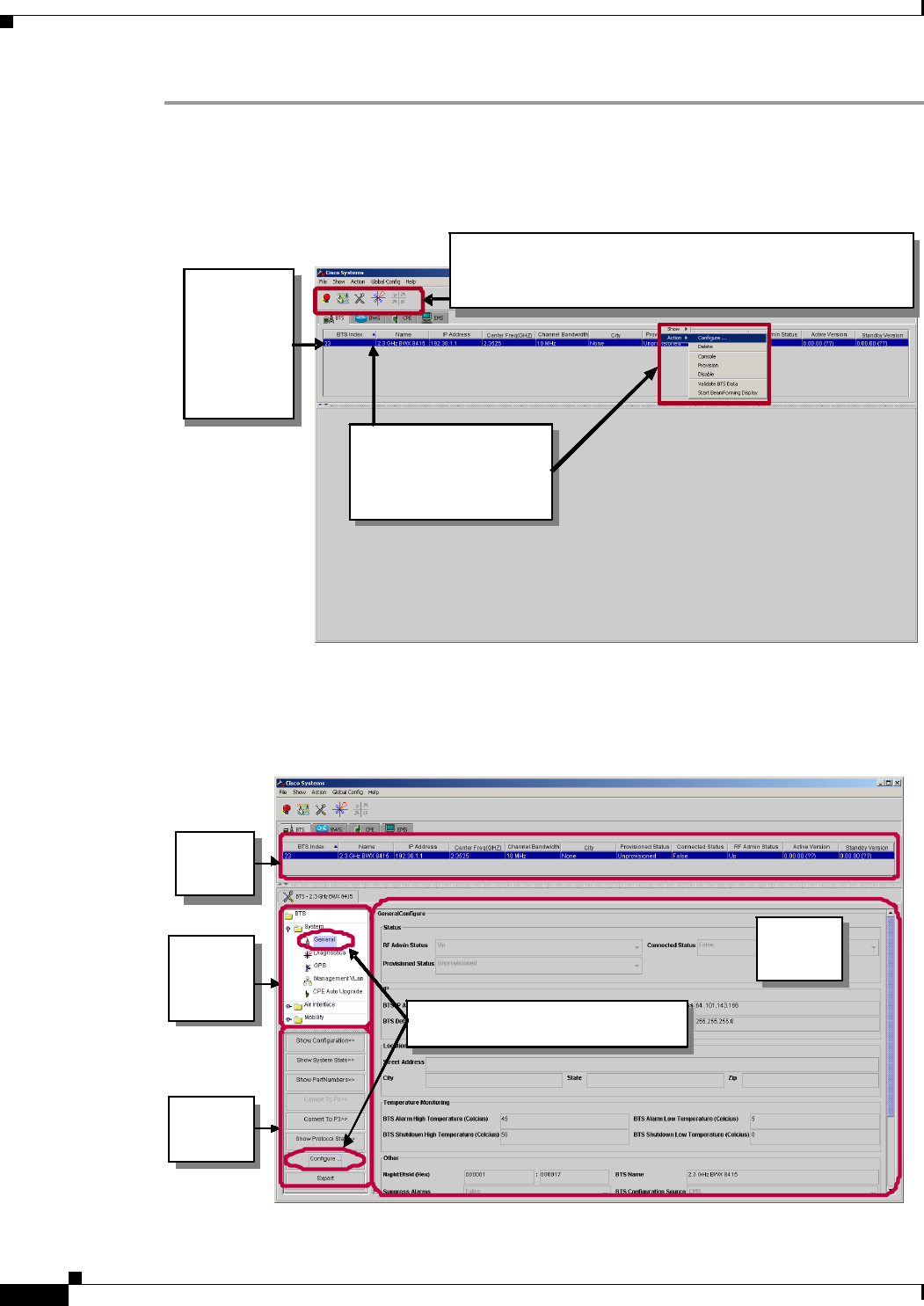
Step 1 From the BTS tab, click on the BTS which is to be configured.
Step 2 Right-click on the selected BTS, pull down the Action menu and select Configure.
Figure 7-14 Configuring the BWX Basestation
Step 3 Select System > General and then click on Configure.
Figure 7-15 Selecting the General Parameters
Click on t he
first BTS.
Notic e that
it turns blue
to indicate
that it is
select ed.
Four of the five icons (Alarm View, Net View, Configure…,
and BWX WiMAX Diagnostic Tool) are now selectable (that
is, not grayed out).
Right-click on the selected
BTS and pull down the
“Acti on”menu. Select
“Confi gure…”
Click on t he
first BTS.
Notic e that
it turns blue
to indicate
that it is
select ed.
Click on t he
first BTS.
Notic e that
it turns blue
to indicate
that it is
select ed.
Click on t he
first BTS.
Notic e that
it turns blue
to indicate
that it is
select ed.
Four of the five icons (Alarm View, Net View, Configure…,
and BWX WiMAX Diagnostic Tool) are now selectable (that
is, not grayed out).
Four of the five icons (Alarm View, Net View, Configure…,
and BWX WiMAX Diagnostic Tool) are now selectable (that
is, not grayed out).
Four of the five icons (Alarm View, Net View, Configure…,
and BWX WiMAX Diagnostic Tool) are now selectable (that
is, not grayed out).
Four of the five icons (Alarm View, Net View, Configure…,
and BWX WiMAX Diagnostic Tool) are now selectable (that
is, not grayed out).
Right-click on the selected
BTS and pull down the
“Acti on”menu. Select
“Confi gure…”
Right-click on the selected
BTS and pull down the
“Acti on”menu. Select
“Confi gure…”
Right-click on the selected
BTS and pull down the
“Acti on”menu. Select
“Confi gure…”
Right-click on the selected
BTS and pull down the
“Acti on”menu. Select
“Confi gure…”
Element
Attribute
Area
Element
Attribute
Ar e a
Element
Attribute
Area
Element
Attribute
Ar e a
Element
Attribute
Area
Element
Attribute
Ar e a
Element
Attribute
Area
Element
Attribute
Ar e a
Element
Attribute
Area
Element
Attribute
Ar e a
Element
Attribute
Area
Element
Attribute
Ar e a
Element
Attribute
Area
Element
Attribute
Ar e a
Element
Attribute
Area
Element
Attribute
Ar e a
Element
Attribute
Area
Element
Attribute
Ar e a
Element
Attribute
Area
Element
Attribute
Ar e a
Element
Attribute
Area
Element
Attribute
Ar e a
Element
Attribute
Area
Element
Attribute
Ar e a
Config.
Element
Tree
Area
Config.
Element
Tree
Area
Config.
Element
Tree
Area
Config.
Element
Tree
Area
Config.
Element
Tree
Area
Config.
Element
Tree
Area
Config.
Element
Tree
Area
Config.
Element
Tree
Area
Element
Actions
Area
Element
Actions
Area
Element
Actions
Area
Element
Actions
Area
Element
Actions
Area
Element
Actions
Area
Element
Actions
Area
Element
Actions
Area
Element
ID List
Area
Element
ID List
Ar e a
Element
ID List
Area
Element
ID List
Ar e a
Element
ID List
Area
Element
ID List
Ar e a
Element
ID List
Area
Element
ID List
Ar e a
Config.
Element
Tree
Area
Config.
Element
Tree
Area
Config.
Element
Tree
Area
Config.
Element
Tree
Area
Config.
Element
Tree
Area
Config.
Element
Tree
Area
Config.
Element
Tree
Area
Config.
Element
Tree
Area
Config.
Element
Tree
Area
Config.
Element
Tree
Area
Config.
Element
Tree
Area
Config.
Element
Tree
Area
Config.
Element
Tree
Area
Config.
Element
Tree
Area
Config.
Element
Tree
Area
Config.
Element
Tree
Area
Element
Actions
Area
Element
Actions
Area
Element
Actions
Area
Element
Actions
Area
Element
Actions
Area
Element
Actions
Area
Element
Actions
Area
Element
Actions
Area
Element
Actions
Area
Element
Actions
Area
Element
Actions
Area
Element
Actions
Area
Element
Actions
Area
Element
Actions
Area
Element
Actions
Area
Element
Actions
Area
Element
ID List
Area
Element
ID List
Ar e a
Element
ID List
Area
Element
ID List
Ar e a
Element
ID List
Area
Element
ID List
Ar e a
Element
ID List
Area
Element
ID List
Ar e a
Element
ID List
Area
Element
ID List
Ar e a
Element
ID List
Area
Element
ID List
Ar e a
Element
ID List
Area
Element
ID List
Ar e a
Element
ID List
Area
Element
ID List
Ar e a
With “System – General” selected,
Click on “Con fi gur e…”.
With “System – General” selected,
Click on “Con fi gur e…”.
With “System – General” selected,
Click on “Con fi gur e…”.
Element
Attribute
Area
Element
Attribute
Ar e a
Element
Attribute
Area
Element
Attribute
Ar e a
Element
Attribute
Area
Element
Attribute
Ar e a
Element
Attribute
Area
Element
Attribute
Ar e a
Element
Attribute
Area
Element
Attribute
Ar e a
Element
Attribute
Area
Element
Attribute
Ar e a
Element
Attribute
Area
Element
Attribute
Ar e a
Element
Attribute
Area
Element
Attribute
Ar e a
Element
Attribute
Area
Element
Attribute
Ar e a
Element
Attribute
Area
Element
Attribute
Ar e a
Element
Attribute
Area
Element
Attribute
Ar e a
Element
Attribute
Area
Element
Attribute
Ar e a
Element
Attribute
Area
Element
Attribute
Ar e a
Element
Attribute
Area
Element
Attribute
Ar e a
Element
Attribute
Area
Element
Attribute
Ar e a
Element
Attribute
Area
Element
Attribute
Ar e a
Element
Attribute
Area
Element
Attribute
Ar e a
Element
Attribute
Area
Element
Attribute
Ar e a
Element
Attribute
Area
Element
Attribute
Ar e a
Element
Attribute
Area
Element
Attribute
Ar e a
Element
Attribute
Area
Element
Attribute
Ar e a
Element
Attribute
Area
Element
Attribute
Ar e a
Element
Attribute
Area
Element
Attribute
Ar e a
Element
Attribute
Area
Element
Attribute
Ar e a
Config.
Element
Tree
Area
Config.
Element
Tree
Area
Config.
Element
Tree
Area
Config.
Element
Tree
Area
Config.
Element
Tree
Area
Config.
Element
Tree
Area
Config.
Element
Tree
Area
Config.
Element
Tree
Area
Element
Actions
Area
Element
Actions
Area
Element
Actions
Area
Element
Actions
Area
Element
Actions
Area
Element
Actions
Area
Element
Actions
Area
Element
Actions
Area
Element
ID List
Area
Element
ID List
Ar e a
Element
ID List
Area
Element
ID List
Ar e a
Element
ID List
Area
Element
ID List
Ar e a
Element
ID List
Area
Element
ID List
Ar e a
Config.
Element
Tree
Area
Config.
Element
Tree
Area
Config.
Element
Tree
Area
Config.
Element
Tree
Area
Config.
Element
Tree
Area
Config.
Element
Tree
Area
Config.
Element
Tree
Area
Config.
Element
Tree
Area
Config.
Element
Tree
Area
Config.
Element
Tree
Area
Config.
Element
Tree
Area
Config.
Element
Tree
Area
Config.
Element
Tree
Area
Config.
Element
Tree
Area
Config.
Element
Tree
Area
Config.
Element
Tree
Area
Element
Actions
Area
Element
Actions
Area
Element
Actions
Area
Element
Actions
Area
Element
Actions
Area
Element
Actions
Area
Element
Actions
Area
Element
Actions
Area
Element
Actions
Area
Element
Actions
Area
Element
Actions
Area
Element
Actions
Area
Element
Actions
Area
Element
Actions
Area
Element
Actions
Area
Element
Actions
Area
Element
ID List
Area
Element
ID List
Ar e a
Element
ID List
Area
Element
ID List
Ar e a
Element
ID List
Area
Element
ID List
Ar e a
Element
ID List
Area
Element
ID List
Ar e a
Element
ID List
Area
Element
ID List
Ar e a
Element
ID List
Area
Element
ID List
Ar e a
Element
ID List
Area
Element
ID List
Ar e a
Element
ID List
Area
Element
ID List
Ar e a
Config.
Element
Tree
Area
Config.
Element
Tree
Area
Config.
Element
Tree
Area
Config.
Element
Tree
Area
Config.
Element
Tree
Area
Config.
Element
Tree
Area
Config.
Element
Tree
Area
Config.
Element
Tree
Area
Element
Actions
Area
Element
Actions
Area
Element
Actions
Area
Element
Actions
Area
Element
Actions
Area
Element
Actions
Area
Element
Actions
Area
Element
Actions
Area
Element
ID List
Area
Element
ID List
Ar e a
Element
ID List
Area
Element
ID List
Ar e a
Element
ID List
Area
Element
ID List
Ar e a
Element
ID List
Area
Element
ID List
Ar e a
Config.
Element
Tree
Area
Config.
Element
Tree
Area
Config.
Element
Tree
Area
Config.
Element
Tree
Area
Config.
Element
Tree
Area
Config.
Element
Tree
Area
Config.
Element
Tree
Area
Config.
Element
Tree
Area
Config.
Element
Tree
Area
Config.
Element
Tree
Area
Config.
Element
Tree
Area
Config.
Element
Tree
Area
Config.
Element
Tree
Area
Config.
Element
Tree
Area
Config.
Element
Tree
Area
Config.
Element
Tree
Area
Element
Actions
Area
Element
Actions
Area
Element
Actions
Area
Element
Actions
Area
Element
Actions
Area
Element
Actions
Area
Element
Actions
Area
Element
Actions
Area
Element
Actions
Area
Element
Actions
Area
Element
Actions
Area
Element
Actions
Area
Element
Actions
Area
Element
Actions
Area
Element
Actions
Area
Element
Actions
Area
Element
ID List
Area
Element
ID List
Ar e a
Element
ID List
Area
Element
ID List
Ar e a
Element
ID List
Area
Element
ID List
Ar e a
Element
ID List
Area
Element
ID List
Ar e a
Element
ID List
Area
Element
ID List
Ar e a
Element
ID List
Area
Element
ID List
Ar e a
Element
ID List
Area
Element
ID List
Ar e a
Element
ID List
Area
Element
ID List
Ar e a
With “System – General” selected,
Click on “Con fi gur e…”.
With “System – General” selected,
Click on “Con fi gur e…”.
With “System – General” selected,
Click on “Con fi gur e…”.
With “System – General” selected,
Click on “Con fi gur e…”.
With “System – General” selected,
Click on “Con fi gur e…”.
With “System – General” selected,
Click on “Con fi gur e…”.
With “System – General” selected,
Click on “Con fi gur e…”.
With “System – General” selected,
Click on “Con fi gur e…”.
With “System – General” selected,
Click on “Con fi gur e…”.
PRELIMINARY
7-15
BWX 8415 Basestation Installation and Commissioning Guide
OL-19519-01
Chapter 7 Commissioning
7.5.3 Configure a BWX 8415 Basestation
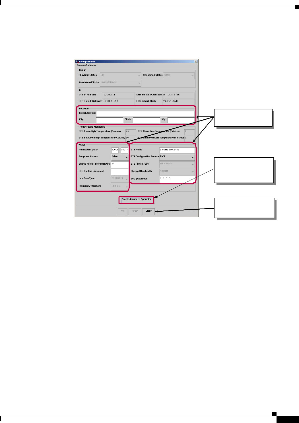
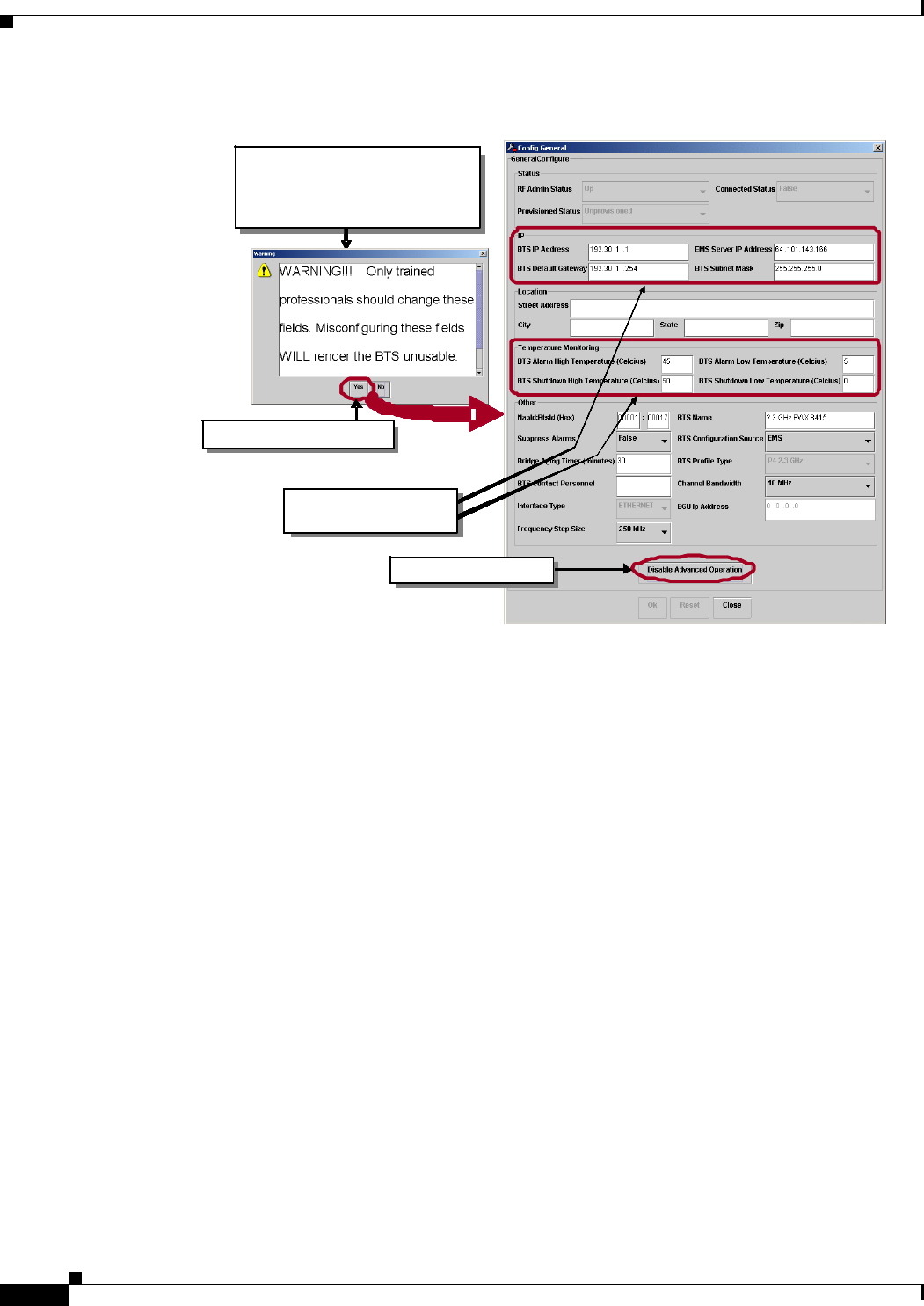
Step 4 Click on Enable Advance Operations to modify additional fields.
Figure 7-16 Enabling Advanced Operations for General Parameters
Step 5 Acknowledge the Warning by clicking on Yes and verify that additional fields are modifiable.
Only the fields in white and
m os t of t he p ull-down f i elds
can be changed.
Click on “Enable Advanced
Op er a ti o n s” to see what
other additional fields
bec om e ava i l a bl e .
Notice that only one of the
three buttons, at the bottom
of the screen, is active.
Only the fields in white and
m os t of t he p ull-down f i elds
can be changed.
Only the fields in white and
m os t of t he p ull-down f i elds
can be changed.
Click on “Enable Advanced
Op er a ti o n s” to see what
other additional fields
bec om e ava i l a bl e .
Click on “Enable Advanced
Op er a ti o n s” to see what
other additional fields
bec om e ava i l a bl e .
Notice that only one of the
three buttons, at the bottom
of the screen, is active.
Notice that only one of the
three buttons, at the bottom
of the screen, is active.
PRELIMINARY
7-16
BWX 8415 Basestation Installation and Commissioning Guide
OL-19519-01
Chapter 7 Commissioning
7.5.3 Configure a BWX 8415 Basestation
Figure 7-17 Enabling Advanced Operations for General Parameters (cont.)
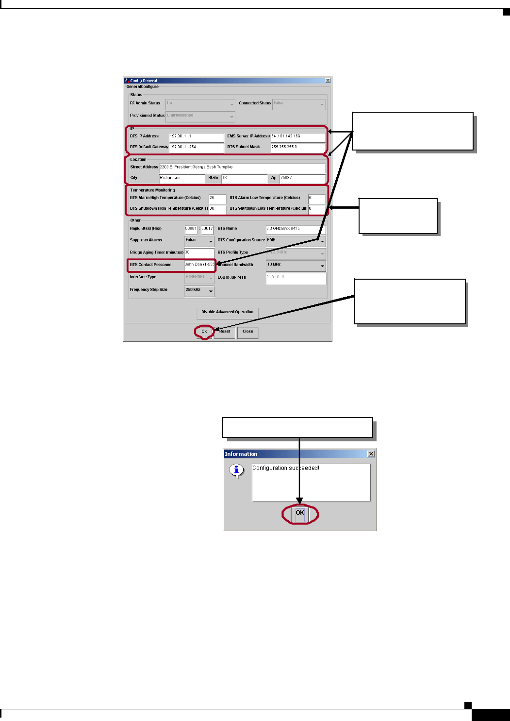
Step 6 Update the necessary fields, to include: IP info, location, and contact personnel.
Step 7 Verify that the BTS High Temperature value is 25 (Celsius) and the BTS Shutdown High Temperature
value is 30 (Celsius).
Step 8 Click on Ok to accept the changes.
New fields are available
for modification.
New fields are available
for modification.
New fields are available
for modification.
Whenever you click on “Enable
Advanced Operat ions”a
warning screen like this one is
open ed .
Click on “Ye s” to proceed.Click on “Ye s” to proceed.Click on “Ye s” to proceed.
Click here to go ba ck. Click here to go ba ck. Click here to go ba ck.
New fields are available
for modification.
New fields are available
for modification.
New fields are available
for modification.
New fields are available
for modification.
New fields are available
for modification.
New fields are available
for modification.
Whenever you click on “Enable
Advanced Operat ions”a
warning screen like this one is
open ed .
Click on “Ye s” to proceed.Click on “Ye s” to proceed.Click on “Ye s” to proceed.
Whenever you click on “Enable
Advanced Operat ions”a
warning screen like this one is
open ed .
Whenever you click on “Enable
Advanced Operat ions”a
warning screen like this one is
open ed .
Whenever you click on “Enable
Advanced Operat ions”a
warning screen like this one is
open ed .
Click on “Ye s” to proceed.Click on “Ye s” to proceed.Click on “Ye s” to proceed.Click on “Ye s” to proceed.Click on “Ye s” to proceed.Click on “Ye s” to proceed.Click on “Ye s” to proceed.Click on “Ye s” to proceed.Click on “Ye s” to proceed.Click on “Ye s” to proceed.Click on “Ye s” to proceed.Click on “Ye s” to proceed.Click on “Ye s” to proceed.Click on “Ye s” to proceed.Click on “Ye s” to proceed.
Click here to go ba ck. Click here to go ba ck. Click here to go ba ck. Click here to go ba ck. Click here to go ba ck. Click here to go ba ck. Click here to go ba ck. Click here to go ba ck. Click here to go ba ck.
PRELIMINARY
7-17
BWX 8415 Basestation Installation and Commissioning Guide
OL-19519-01
Chapter 7 Commissioning
7.5.3 Configure a BWX 8415 Basestation
Figure 7-18 Updating Parameter Fields
Step 9 Click on Ok to continue.
Figure 7-19 Confirmation of Successful Configuration
Update the necessary fi elds.
This includes IP info, Location
and Contact Personnel.
Notice that now the three
buttons at the bottom of the
Screen are active. Click on
“Ok” t o accept the ch an ges.
Notice that now the three
buttons at the bottom of the
Screen are active. Click on
“Ok” t o accept the ch an ges.
Notice that now the three
buttons at the bottom of the
Screen are active. Click on
“Ok” t o accept the ch an ges.
Change the High
Temp values to 25
and 30 (Celsius).
Change the High
Temp values to 25
and 30 (Celsius).
Change the High
Temp values to 25
and 30 (Celsius).
Update the necessary fi elds.
This includes IP info, Location
and Contact Personnel.
Notice that now the three
buttons at the bottom of the
Screen are active. Click on
“Ok” t o accept the ch an ges.
Notice that now the three
buttons at the bottom of the
Screen are active. Click on
“Ok” t o accept the ch an ges.
Notice that now the three
buttons at the bottom of the
Screen are active. Click on
“Ok” t o accept the ch an ges.
Notice that now the three
buttons at the bottom of the
Screen are active. Click on
“Ok” t o accept the ch an ges.
Notice that now the three
buttons at the bottom of the
Screen are active. Click on
“Ok” t o accept the ch an ges.
Notice that now the three
buttons at the bottom of the
Screen are active. Click on
“Ok” t o accept the ch an ges.
Notice that now the three
buttons at the bottom of the
Screen are active. Click on
“Ok” t o accept the ch an ges.
Notice that now the three
buttons at the bottom of the
Screen are active. Click on
“Ok” t o accept the ch an ges.
Notice that now the three
buttons at the bottom of the
Screen are active. Click on
“Ok” t o accept the ch an ges.
Change the High
Temp values to 25
and 30 (Celsius).
Change the High
Temp values to 25
and 30 (Celsius).
Change the High
Temp values to 25
and 30 (Celsius).
Change the High
Temp values to 25
and 30 (Celsius).
Change the High
Temp values to 25
and 30 (Celsius).
Change the High
Temp values to 25
and 30 (Celsius).
Change the High
Temp values to 25
and 30 (Celsius).
Change the High
Temp values to 25
and 30 (Celsius).
Change the High
Temp values to 25
and 30 (Celsius).
Click on “Ok” to continue.Click on “Ok” to continue.Click on “Ok” to continue.
PRELIMINARY
7-18
BWX 8415 Basestation Installation and Commissioning Guide
OL-19519-01
Chapter 7 Commissioning
7.5.3 Configure a BWX 8415 Basestation
7.5.3.2 Set the GPS Parameters
Note The GPS receiver module supports WiMAX certification requirements for high-resolution timing. The
GPS receiver module provides 1 pulse per second (1 PPS) and 10 MHz source.
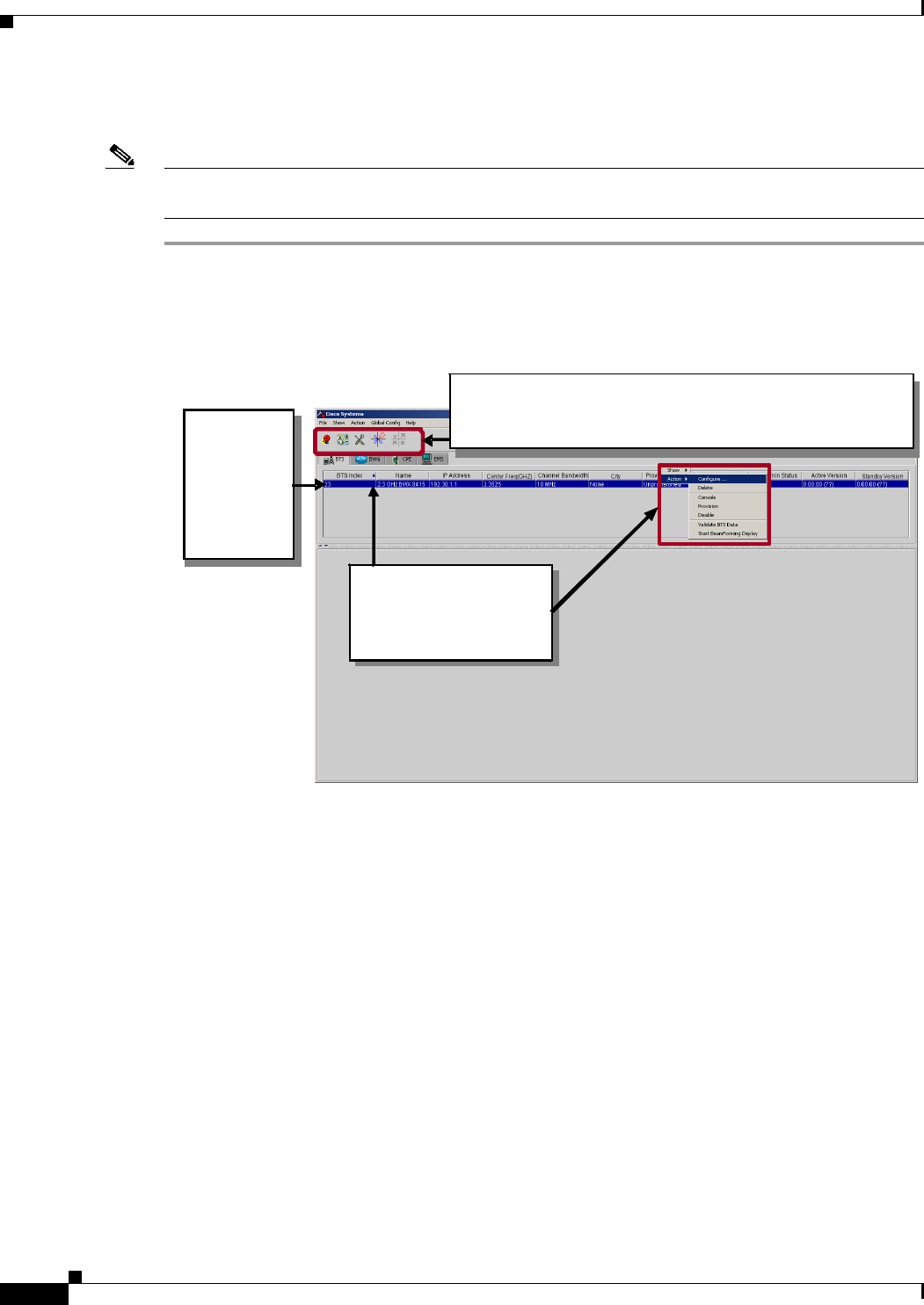
Step 1 From the BTS tab, click on the BTS which is to be configured.
Step 2 Right-click on the selected BTS, pull down the Action menu and select Configure.
Figure 7-20 Configuring the BWX Basestation
Step 3 Select System > GPS and then click on Configure.
Click on t he
first BTS.
Notic e that
it turns blue
to indicate
that it is
select ed.
Four of the five icons (Alarm View, Net View, Configure…,
and BWX WiMAX Diagnostic Tool) are now selectable (that
is, not grayed out).
Right-click on the selected
BTS and pull down the
“Acti on”menu. Select
“Confi gure…”
Click on t he
first BTS.
Notic e that
it turns blue
to indicate
that it is
select ed.
Click on t he
first BTS.
Notic e that
it turns blue
to indicate
that it is
select ed.
Click on t he
first BTS.
Notic e that
it turns blue
to indicate
that it is
select ed.
Four of the five icons (Alarm View, Net View, Configure…,
and BWX WiMAX Diagnostic Tool) are now selectable (that
is, not grayed out).
Four of the five icons (Alarm View, Net View, Configure…,
and BWX WiMAX Diagnostic Tool) are now selectable (that
is, not grayed out).
Four of the five icons (Alarm View, Net View, Configure…,
and BWX WiMAX Diagnostic Tool) are now selectable (that
is, not grayed out).
Four of the five icons (Alarm View, Net View, Configure…,
and BWX WiMAX Diagnostic Tool) are now selectable (that
is, not grayed out).
Right-click on the selected
BTS and pull down the
“Acti on”menu. Select
“Confi gure…”
Right-click on the selected
BTS and pull down the
“Acti on”menu. Select
“Confi gure…”
Right-click on the selected
BTS and pull down the
“Acti on”menu. Select
“Confi gure…”
Right-click on the selected
BTS and pull down the
“Acti on”menu. Select
“Confi gure…”
PRELIMINARY
7-19
BWX 8415 Basestation Installation and Commissioning Guide
OL-19519-01
Chapter 7 Commissioning
7.5.3 Configure a BWX 8415 Basestation
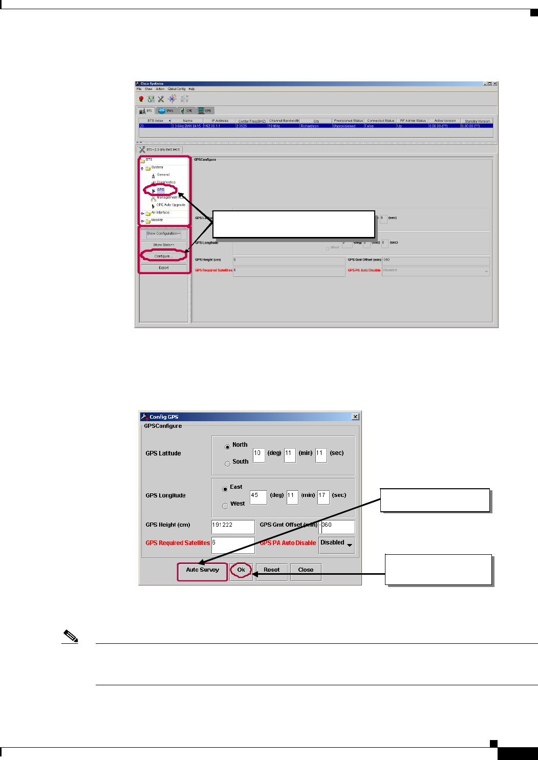
Figure 7-21 Selecting the GPS Parameters
Step 4 Click on Auto Survey to configure the GPS receiver module.
Step 5 Click on Ok to accept the changes.
Figure 7-22 Updating Parameter Fields
Step 6 Click on Ye s in the warning box that will appear when the Auto Survey action is triggered.
Note The Auto Survey action can take up to four (4) hours to complete. An alarm (GPS Receiver Auto Survey
in progress) will appear while the survey is in progress and the BS must be reset for the changes to take
effect.
Step 7 Click on Ok to continue.
With “S ys t em – G en era l” selected,
Click on “Co nfigure…”.
With “S ys t em – G en era l” selected,
Click on “Co nfigure…”.
With “ Sys t e m – G P S ” selected,
Click on “Co nfigure…”.
With “S ys t em – G en era l” selected,
Click on “Co nfigure…”.
With “S ys t em – G en era l” selected,
Click on “Co nfigure…”.
With “ Sys t e m – G P S ” selected,
Click on “Co nfigure…”.
With “S ys t em – G en era l” selected,
Click on “Co nfigure…”.
With “S ys t em – G en era l” selected,
Click on “Co nfigure…”.
With “ Sys t e m – G P S ” selected,
Click on “Co nfigure…”.
Click on “Ok” to accept
the changes.
Click on “Auto Survey.”
Click on “Ok” to accept
the changes.
Click on “Auto Survey.”Click on “Auto Survey.”
PRELIMINARY
7-20
BWX 8415 Basestation Installation and Commissioning Guide
OL-19519-01
Chapter 7 Commissioning
7.5.3 Configure a BWX 8415 Basestation
Figure 7-23 Confirmation of Successful Configuration
7.5.3.3 Set the Layer 1 Parameters
The steps to set the Performance parameters are shown in Figure 7-24 through Figure 7-29. Please refer
to these figures as you read the remainder of this section.
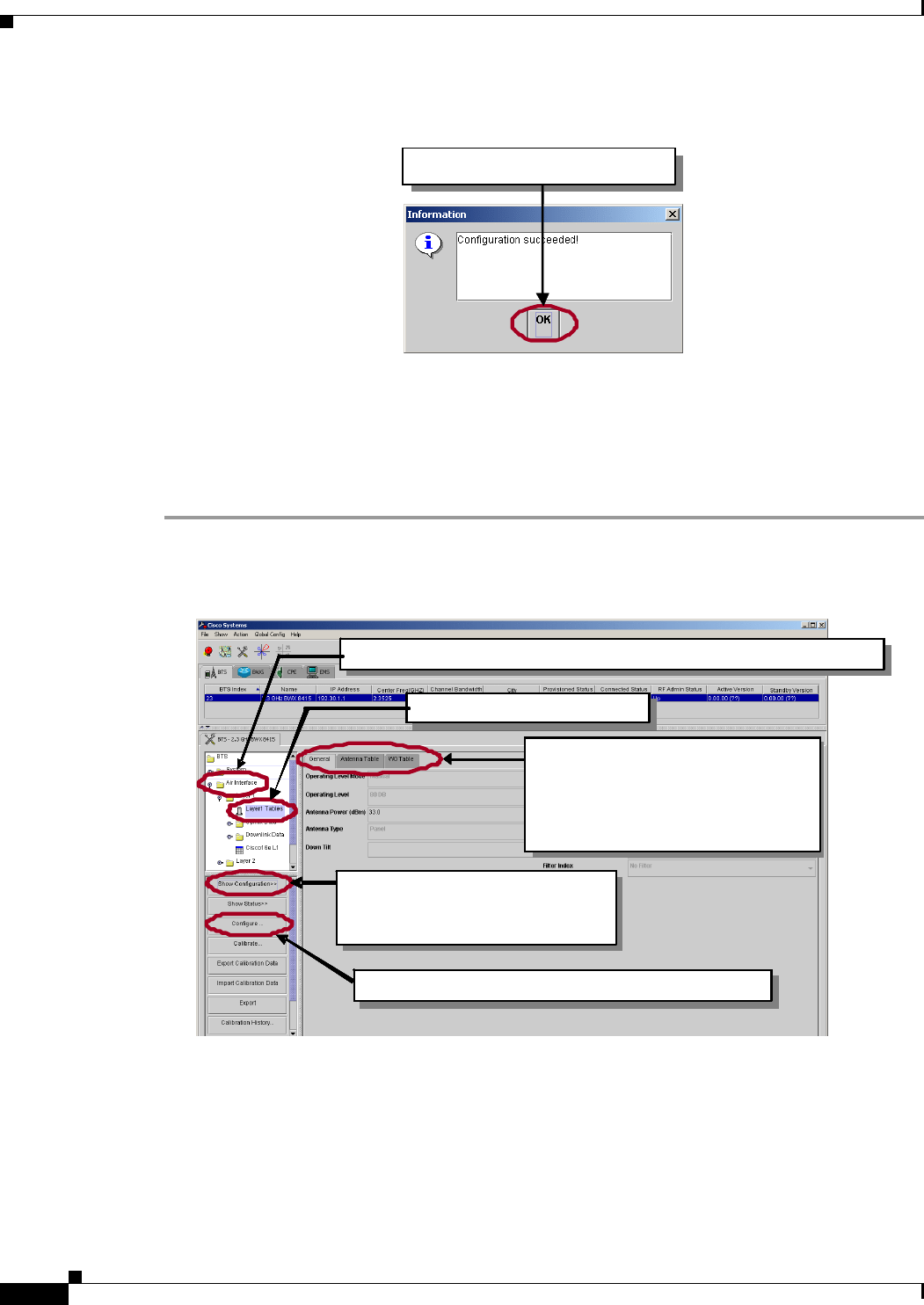
Step 1 Select Air Interface> Layer 1> Layer 1 Tables and then click on Show Configuration and Configure.
Figure 7-24 Selecting the Performance Parameters
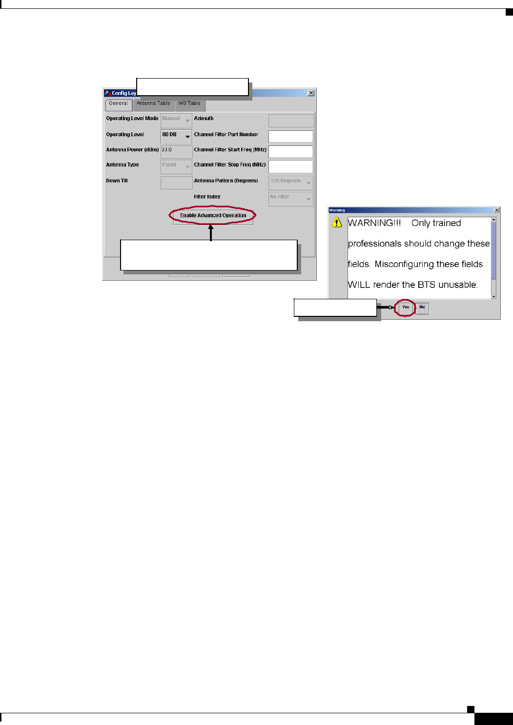
Step 2 Select the General tab.
Step 3 Click on Enable Advance Operations to modify additional fields.
Step 4 Click on Yes in the Warning box.
Click on “Ok” to continue.Click on “Ok” to continue.Click on “Ok” to continue.
In order to make changes, click on “Configure”.In order to make changes, click on “Configure”.
Click on “Show Configuration”
to view the current “Layer 1”
configuration.
Click on “Show Configuration”
to view the current “Layer 1”
configuration.
Click on “Show Configuration”
to view the current “Layer 1”
configuration.
Notice there are 3 tabs . Nothi ng
can b e changed at thi s level. All
fields are grayed out because
“Show Configuration” was
selected.
Click on “Layer1 Ta bles”.
Cl ick on this icon to op en the “Air Interface” branch of the tree.
In order to make changes, click on “Configure”.In order to make changes, click on “Configure”.In order to make changes, click on “Configure”.In order to make changes, click on “Configure”.
Click on “Show Configuration”
to view the current “Layer 1”
configuration.
Click on “Show Configuration”
to view the current “Layer 1”
configuration.
Click on “Show Configuration”
to view the current “Layer 1”
configuration.
Click on “Show Configuration”
to view the current “Layer 1”
configuration.
Click on “Show Configuration”
to view the current “Layer 1”
configuration.
Click on “Show Configuration”
to view the current “Layer 1”
configuration.
Notice there are 3 tabs . Nothi ng
can b e changed at thi s level. All
fields are grayed out because
“Show Configuration” was
selected.
Notice there are 3 tabs . Nothi ng
can b e changed at thi s level. All
fields are grayed out because
“Show Configuration” was
selected.
Click on “Layer1 Ta bles”.Click on “Layer1 Ta bles”.Click on “Layer1 Ta bles”.
Cl ick on this icon to op en the “Air Interface” branch of the tree. Cl ick on this icon to op en the “Air Interface” branch of the tree. Cl ick on this icon to op en the “Air Interface” branch of the tree.
PRELIMINARY
7-21
BWX 8415 Basestation Installation and Commissioning Guide
OL-19519-01
Chapter 7 Commissioning
7.5.3 Configure a BWX 8415 Basestation
Figure 7-25 Enabling Advanced Operation for Layer 1 Parameters
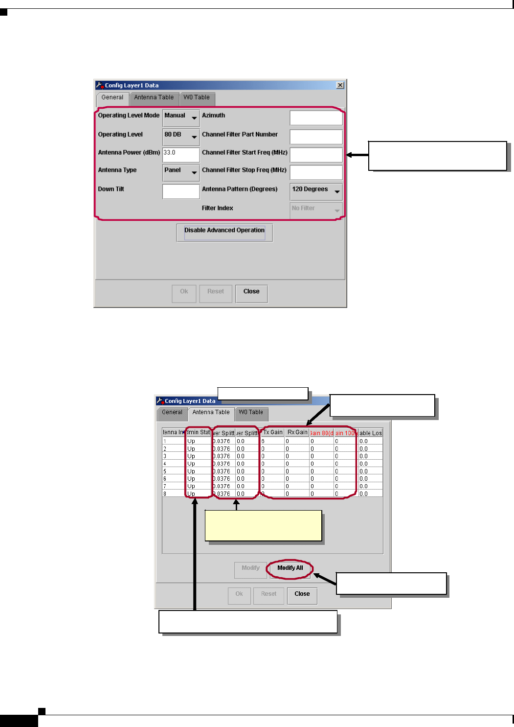
Step 5 Enter the values in the following fields, as shown in Figure 7-26 below:
• Operating Level Mode = use value given by service provider (Auto/Manual)
• Operating Level = use value given by service provider (100dB/80dB/60dB)
• Antenna Power = use value given by service provider (20-35)
• Antenna Type = Panel
• Down Tilt = use value given by service provider
• Azimuth = per directions given to Installer
• Channel Filter Part Number = from sticker on channel filter
• Channel Filter Start Freq = use value given by service provider
• Channel Filter Stop Freq = use value given by service provider
• Antenna Pattern = use value given by service provider (120/90)
Select the General tab.
Click on Yes.
Select the General tab. Select the General tab. Select the General tab.
Click on Enable Advanced Operation
to enable more f ields to be changed.
Click on Enable Advanced Operation
to enable more f ields to be changed.
Click on Enable Advanced Operation
to enable more f ields to be changed.
Click on Enable Advanced Operation
to enable more f ields to be changed.
Click on Yes. Click on Yes. Click on Yes.
Select the General tab.
Click on Yes.
Select the General tab. Select the General tab. Select the General tab.
Click on Enable Advanced Operation
to enable more f ields to be changed.
Click on Enable Advanced Operation
to enable more f ields to be changed.
Click on Enable Advanced Operation
to enable more f ields to be changed.
Click on Enable Advanced Operation
to enable more f ields to be changed.
Click on Enable Advanced Operation
to enable more f ields to be changed.
Click on Enable Advanced Operation
to enable more f ields to be changed.
Click on Enable Advanced Operation
to enable more f ields to be changed.
Click on Enable Advanced Operation
to enable more f ields to be changed.
Click on Yes. Click on Yes. Click on Yes.
PRELIMINARY
7-22
BWX 8415 Basestation Installation and Commissioning Guide
OL-19519-01
Chapter 7 Commissioning
7.5.3 Configure a BWX 8415 Basestation
Figure 7-26 Changing the Layer 1 Parameters
Step 6 Select the second tab, Antenna Table.
Step 7 Select Modify All to change the values of any field.
Figure 7-27 Antenna Table Tab
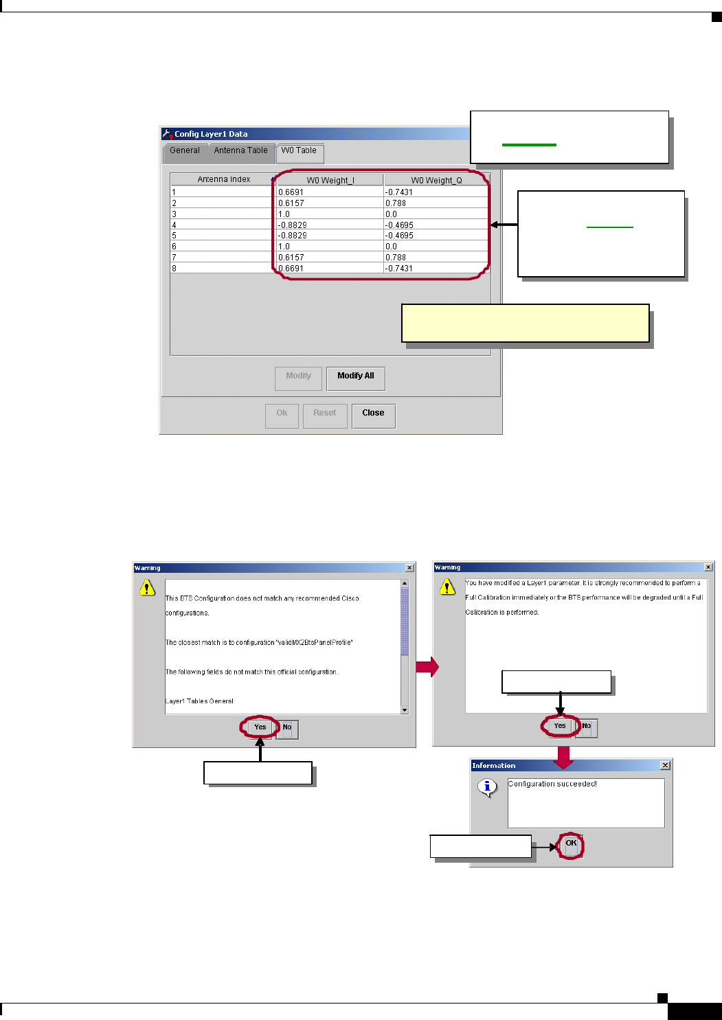
Step 8 Select the third tab, W0 Table.
Update the General parameters,
per the si te specifications.
Update the General parameters,
per the si te specifications.
Update the General parameters,
per the si te specifications.
Update the General parameters,
per the si te specifications.
Select the s econd tab. These values are returned by
the “full calibration” process.
These values are loaded from
The f lash m emory within the BS
(D iscuss ed in the next section.)
These fields turn transmission and reception, for
each antenna element, ON or OFF individually.
Click on “Modify All” to c hange
any of the fields.
Select the s econd tab. Select the s econd tab. These values are returned by
the “full calibration” process.
These values are returned by
the “full calibration” process.
These values are returned by
the “full calibration” process.
These values are loaded from
The f lash m emory within the BS
(D iscuss ed in the next section.)
These values are loaded from
The f lash m emory within the BS
(D iscuss ed in the next section.)
These values are loaded from
The f lash m emory within the BS
(D iscuss ed in the next section.)
These fields turn transmission and reception, for
each antenna element, ON or OFF individually.
These fields turn transmission and reception, for
each antenna element, ON or OFF individually.
Click on “Modify All” to c hange
any of the fields.
Click on “Modify All” to c hange
any of the fields.
Click on “Modify All” to c hange
any of the fields.
PRELIMINARY
7-23
BWX 8415 Basestation Installation and Commissioning Guide
OL-19519-01
Chapter 7 Commissioning
7.5.3 Configure a BWX 8415 Basestation
Figure 7- 2 8 W 0 Ta b l e Ta b
Step 9 Click on Ok, at the bottom of the screen, to continue.
Step 10 Click on Yes in the warning boxes and click Ok to continue.
Figure 7-29 Layer 1 Warning Box
These parameters characterize
the g eom etry of the BWX
Base station Antenna.
These parameters characterize
the g eom etry of the BWX
Base station Antenna.
These parameters characterize
the g eom etry of the BWX 8415
Basestation.
For Panel antenn as, the
values are different for the
different a ntenna e leme nts,
but the pattern is rep eated
for each sub-carrier.
For Panel antenn as, the
values are different for the
different a ntenna e leme nts,
but the pattern is rep eated
for each sub-carrier.
Th e cor rect va lue s will be loaded from
the script supplied with the antenna.
Th e cor rect va lue s will be loaded from
the script supplied with the antenna.
Th e cor rect va lue s will be loaded from
th e fl ash memo ry with in t he BS.
These parameters characterize
the g eom etry of the BWX
Base station Antenna.
These parameters characterize
the g eom etry of the BWX
Base station Antenna.
These parameters characterize
the g eom etry of the BWX 8415
Basestation.
These parameters characterize
the g eom etry of the BWX
Base station Antenna.
These parameters characterize
the g eom etry of the BWX
Base station Antenna.
These parameters characterize
the g eom etry of the BWX 8415
Basestation.
For Panel antenn as, the
values are different for the
different a ntenna e leme nts,
but the pattern is rep eated
for each sub-carrier.
For Panel antenn as, the
values are different for the
different a ntenna e leme nts,
but the pattern is rep eated
for each sub-carrier.
For Panel antenn as, the
values are different for the
different a ntenna e leme nts,
but the pattern is rep eated
for each sub-carrier.
For Panel antenn as, the
values are different for the
different a ntenna e leme nts,
but the pattern is rep eated
for each sub-carrier.
For Panel antenn as, the
values are different for the
different a ntenna e leme nts,
but the pattern is rep eated
for each sub-carrier.
For Panel antenn as, the
values are different for the
different a ntenna e leme nts,
but the pattern is rep eated
for each sub-carrier.
Th e cor rect va lue s will be loaded from
the script supplied with the antenna.
Th e cor rect va lue s will be loaded from
the script supplied with the antenna.
Th e cor rect va lue s will be loaded from
th e fl ash memo ry with in t he BS.
Th e cor rect va lue s will be loaded from
the script supplied with the antenna.
Th e cor rect va lue s will be loaded from
the script supplied with the antenna.
Th e cor rect va lue s will be loaded from
th e fl ash memo ry with in t he BS.
Click on “ Ok”. Click on “ Ok”. Click on “ Ok”. Click on “ Ok”.
Click on “Yes”. Click on “Yes”.
Click on “Yes”. Click on “Yes”.
Click on “ Ok”. Click on “ Ok”. Click on “ Ok”. Click on “ Ok”.
Click on “Yes”. Click on “Yes”.
Click on “ Ok”. Click on “ Ok”. Click on “ Ok”. Click on “ Ok”.
Click on “Yes”. Click on “Yes”. Click on “Yes”. Click on “Yes”.
Click on “Yes”. Click on “Yes”. Click on “Yes”. Click on “Yes”. Click on “Yes”. Click on “Yes”. Click on “Yes”. Click on “Yes”.
PRELIMINARY
7-24
BWX 8415 Basestation Installation and Commissioning Guide
OL-19519-01
Chapter 7 Commissioning
7.5.3 Configure a BWX 8415 Basestation
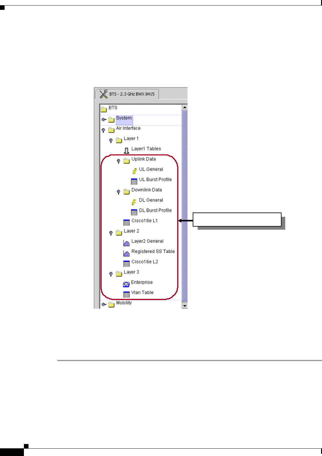
7.5.3.4 Other Parameters – Optimized Settings
The rest of the Layer1 and Layer2 values will be left at the defaults by the Installer, unless otherwise
specified (see Figure 7-30).
Figure 7-30 Defaulted Layer1 / Layer2 / Layer3 Values
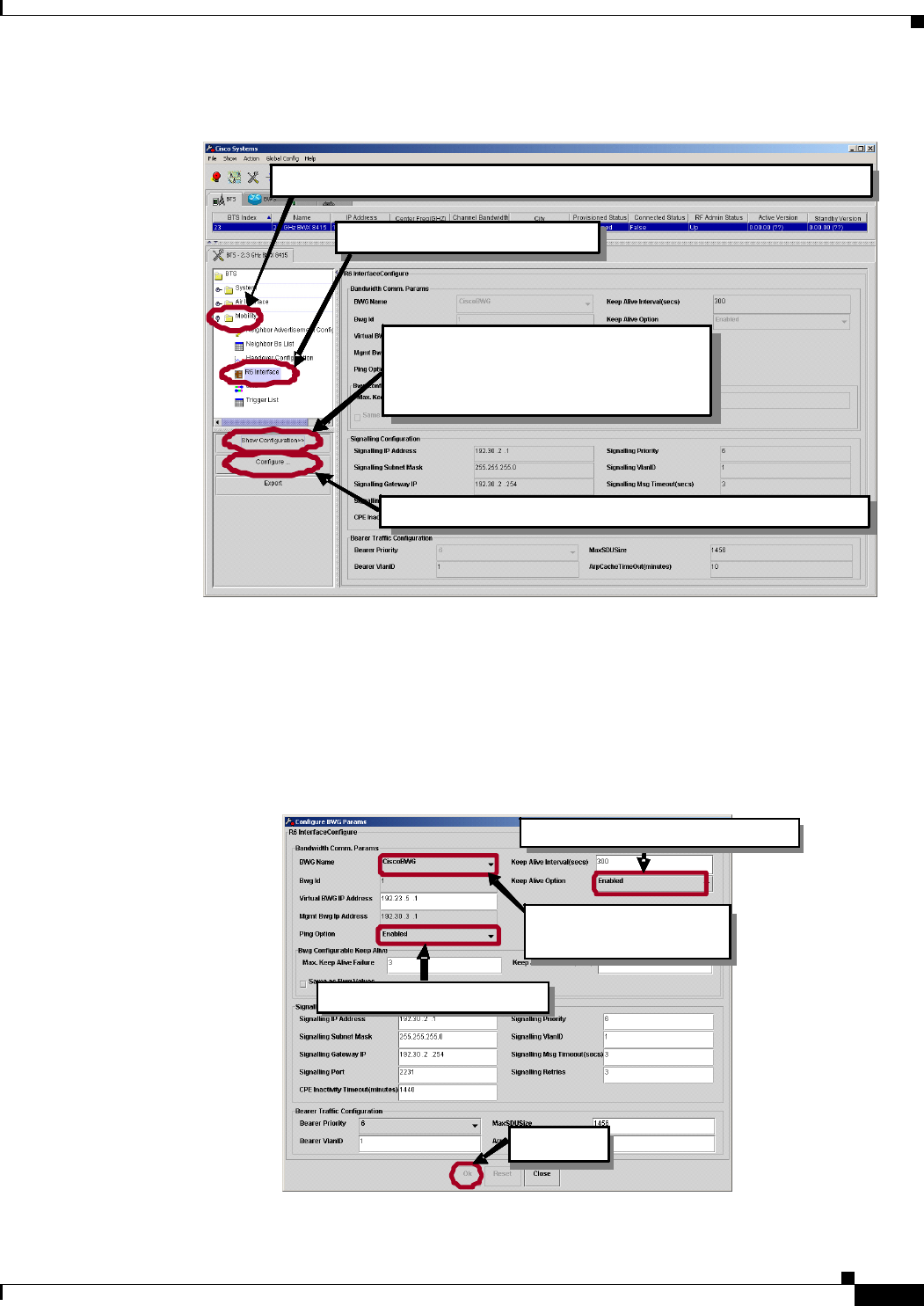
7.5.3.5 Set the R6 Interface Parameters
The steps to set the R6 Interface parameters are shown in Figure 7-31 through Figure 7-33. Please refer
to these figures as you read the remainder of this section.
Step 1 Select Mobility > R6 Interface and then click on Show Configuration and Configure.
Layer1 / Layer2 / Layer3 TabsLayer1 / Layer2 / Layer3 TabsLayer1 / Layer2 / Layer3 TabsLayer1 / Layer2 / Layer3 TabsLayer1 / Layer2 / Layer3 TabsLayer1 / Layer2 / Layer3 TabsLayer1 / Layer2 / Layer3 TabsLayer1 / Layer2 / Layer3 TabsLayer1 / Layer2 / Layer3 TabsLayer1 / Layer2 / Layer3 TabsLayer1 / Layer2 / Layer3 TabsLayer1 / Layer2 / Layer3 Tabs
PRELIMINARY
7-25
BWX 8415 Basestation Installation and Commissioning Guide
OL-19519-01
Chapter 7 Commissioning
7.5.3 Configure a BWX 8415 Basestation
Figure 7-31 Selecting the R6 Interface Parameters
Step 2 Select the BWG Name from the drop down menu.
Step 3 Set the Ping Option to Enable.
Step 4 Set the Keep Alive Option to Enable.
Step 5 Click on Ok, at the bottom of the screen, to continue.
Figure 7-32 Changing the R6 Interface Parameters
Click on this icon to open the “Mob ility” branch of the tree.
Click on “R6 Interface”.
In order to make changes, click on “C onfigure”.
Click on “Show Configuration”
to view the current R6 Interface
configuration.
Click on this icon to open the “Mob ility” branch of the tree. Click on this icon to open the “Mob ility” branch of the tree.
Click on “R6 Interface”. Click on “R6 Interface”.
In order to make changes, click on “C onfigure”. In order to make changes, click on “C onfigure”.
Click on “Show Configuration”
to view the current R6 Interface
configuration.
Click on “Show Configuration”
to view the current R6 Interface
configuration.
Set the Ping Option to Enable.
Cl i ck o n “Ok”. Cl i ck o n “Ok”. Cl i ck o n “Ok”.
Set the Keep Alive Option to Enable.
Select the BWG name
From the d rop down menu.
Set the Ping Option to Enable. Set the Ping Option to Enable.
Cl i ck o n “Ok”. Cl i ck o n “Ok”. Cl i ck o n “Ok”. Cl i ck o n “Ok”. Cl i ck o n “Ok”. Cl i ck o n “Ok”.
Set the Keep Alive Option to Enable. Set the Keep Alive Option to Enable.
Select the BWG name
From the d rop down menu.
Select the BWG name
From the d rop down menu.
PRELIMINARY
7-26
BWX 8415 Basestation Installation and Commissioning Guide
OL-19519-01
Chapter 7 Commissioning
7.5.3 Configure a BWX 8415 Basestation
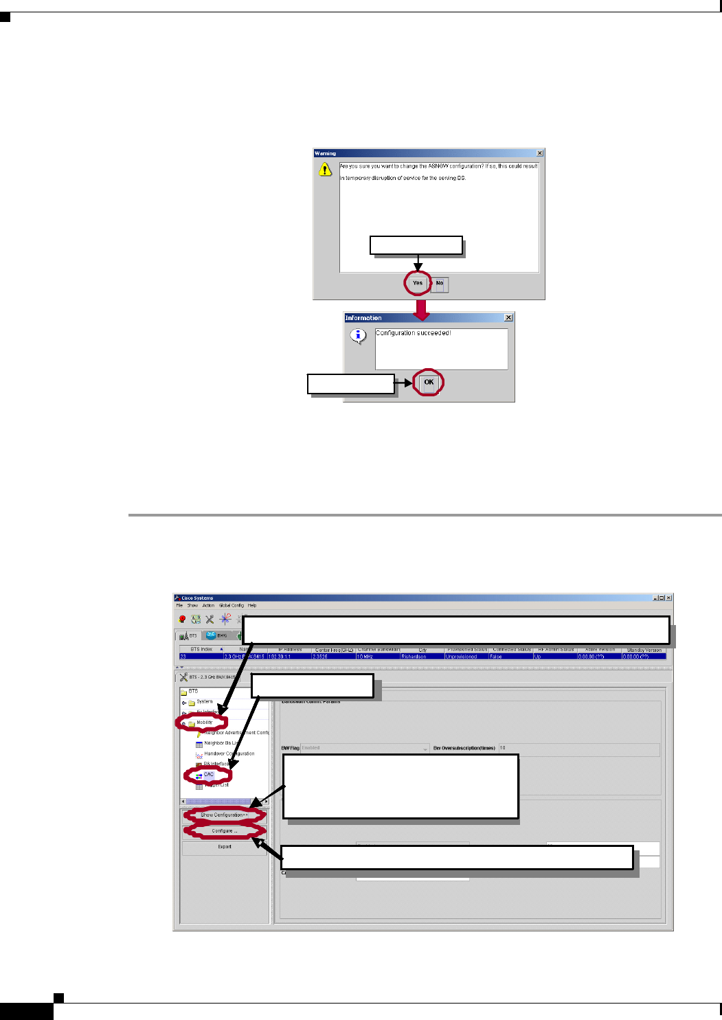
Step 6 Click on Yes in the warning box and click Ok in the Information box to continue.
Figure 7-33 R6 Interface Warning & Information Boxes
7.5.3.6 Set the Call Admission Control (CAC) Parameters
The steps to set the CAC parameters are shown in Figure 7-34 through Figure 7-36. Please refer to these
figures as you read the remainder of this section.
Step 1 Select Mobility > CAC and then click on Show Configuration and Configure.
Figure 7-34 Selecting the CAC Parameters
Click on “Ok”.
Click on “Yes ”.
Click on “Ok”. Click on “Ok”. Click on “Ok”. Click on “Ok”.
Click on “Yes ”. Click on “Yes ”.
Click on this ico n to open t he “Mobili ty” branch of the t ree.
In order to make changes, click on “Configure”.
Click on “Show Configuration”
to view th e current CAC
confi guratio n.
Click on “CAC ”.
Click on this ico n to open t he “Mobili ty” branch of the t ree.Click on this ico n to open t he “Mobili ty” branch of the t ree.
In order to make changes, click on “Configure”.
Click on “Show Configuration”
to view th e current CAC
confi guratio n.
Click on “CAC ”.Click on “CAC ”.
PRELIMINARY
7-27
BWX 8415 Basestation Installation and Commissioning Guide
OL-19519-01
Chapter 7 Commissioning
7.5.3 Configure a BWX 8415 Basestation
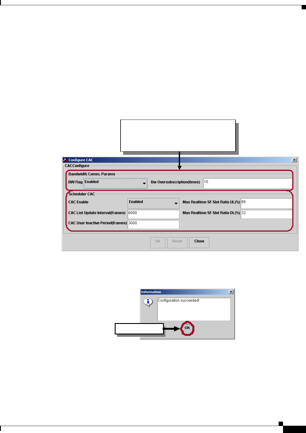
Step 2 Verify that the following default values are set for the CAC fields (refer to Figure 7-35):
Bw flag: Disabled
Bw oversubscription: 10
Cac enable : Enabled
List update interval: 6000
User inactive period: 3000
SF slot ration UL: 66
SF slot ration DL: 32
Figure 7-35 Verifying the Default Values for CAC Configure
Step 3 Click Ok in the Information box to continue.
Figure 7-36 CAC Information Boxes
Verify that the default values for
CAC Configure match those listed
in step 2.
Verify that the default values for
CAC Configure match those listed
in step 2.
Verify that the default values for
CAC Configure match those listed
in step 2.
Verify that the default values for
CAC Configure match those listed
in step 2.
Click on “Ok”. Click on “Ok”. Click on “Ok”.
PRELIMINARY
7-28
BWX 8415 Basestation Installation and Commissioning Guide
OL-19519-01
Chapter 7 Commissioning
7.6 Power Up and Provision the BWX 8415 Basestation
7.6 Power Up and Provision the BWX 8415 Basestation
Reference: BWX EMS Alarm Resolution Reference Manual
7.6.1 Prerequisites
• The EMS must be up and IP-reachable from the BS
• The BWG must be running and configured
• The BS must have been already added to and configured in the EMS
• All equipment in the system must be IP-reachable
• If a laptop with a Test EMS is being used (recommended procedure during commissioning), connect
this laptop to the BS via a Telnet session
Note The Telnet session will not be established until after the BS has booted up.
• Make sure the ‘Test’ EMS server is running on a laptop
• Open a terminal emulation session using one of the following programs:
–
Tera Term Pro
–
HyperTerm
–
Other terminal emulation programs
• Verify the serial port settings
Figure 7-37 Serial Port Settings
PRELIMINARY
7-29
BWX 8415 Basestation Installation and Commissioning Guide
OL-19519-01
Chapter 7 Commissioning
7.6.2 BWX 8415 Basestation Bootup
7.6.2 BWX 8415 Basestation Bootup
7.6.2.1 Power On
Step 1 With the laptop connected to the BS, through the backhaul network and TeraTerm Pro or Hyperterm
running, power up the BS.
Step 2 The system boot sequence starts. When the “Press any key to stop auto-boot...” prompt appears, DO
NOT press any keys. (Example 7-1).
Example 7-1 System Boot Sequence Begins (NEED NEW BOOT SEQUENCE SCREENSHOTS)
Step 3 When the “Auto-booting (Enter “configure setup)” prompt appears, type the word config before the
countdown reaches zero (Example 7-2).
Step 4 At the boot prompt, type p and hit <Enter> to see the current value of the boot parameters
(Example 7-2).
Step 5 At the boot prompt type c and hit <Enter> to configure the boot parameters, one at a time (Example 7-2).
Note Each time you hit <Enter> the next parameter and its current value are displayed and you have the
opportunity to type a new value. When an incorrect parameter appears, type the correct value and hit
<Enter> to continue.
Press any key to stop auto-boot...
0
auto-booting...
boot device : ataa
unit number : 0
processor number : 0
host name : host
file name : core
inet on ethernet (e) : 192.168.1.100:fffff800
inet on backplane (b): 10.0.0.1:fffffffc
host inet (h) : 192.168.1.220
gateway inet (g) : 192.168.1.1
user (u) : ate
ftp password (pw) : ate
flags (f) : 0x8
target name (tn) : nero
startup script (s) : loads/ldlineup
other (o) : mv0
CPLD Firmware Version: 0x18
Attaching to ATA disk device... done.
Loading /ata0a/LOADS/BTSB/core...22257072
Starting at 0x10000...
WHEN YOU SEE THIS PROMPT,
DON’T PRESS ANY KEY!!!
In a second or two, a "0" will be displayed and the
boot sequence will contine…
But if If you hit any key, a “1” will be displayed, the
boot process will be interrupted, and you will be
taken into the VxWorks shell (you will see the
VxWorks Boot Prompt).
THERE IS NO REASON FOR YOU TO GO INSIDE
THE VxWorks SHELL!!!!!
Ignore all this
PRELIMINARY
7-30
BWX 8415 Basestation Installation and Commissioning Guide
OL-19519-01
Chapter 7 Commissioning
7.6.2 BWX 8415 Basestation Bootup
Example 7-2 System Boot Sequence (NEED NEW BOOT SEQUENCE SCREENSHOTS)
Step 6 Enter p to verify(Example 7-3).
Step 7 When all changes have been made, type @ and hit <Enter> to resume the boot process (Example 7-3).
Auto-booting (Enter "config" for setup)... 17config
[Navini Boot]:
[Navini Boot]:
[Navini Boot]: p
date and time : 10/22/2008[14:21]
autoboot countdown : delayed
ems inet : 192.168.1.220
snmp community : public
traffic path : enet
mac address : 00:04:6a:00:3b:cc
ip on enet (active) : 192.168.1.100
ip on enet (standby) : 192.168.1.101
netmask on enet : 255.255.248.0
mgmt vlan id|priority: 1:0 [1-4094]:[0-7]
ip on backplane : 10.0.0.1
gateway on enet : 192.168.1.1
[Navini Boot]:
[Navini Boot]:
[Navini Boot]: c
date and time : 10/22/2008[14:22]
MM/dd/yyyy[hh:mm]
autoboot countdown : delayed [quick|delayed]
ems inet : 192.168.1.220 192.168.2.208
snmp community : public
traffic path : enet
mac address : 00:04:6a:00:3b:cc
ip on enet (active) : 192.168.1.100 192.168.2.67
ip on enet (standby) : 192.168.1.101
netmask on enet : 255.255.248.0 255.255.255.0
mgmt vlan id|priority: 1:0 [1-4094]:[0-7]
ip on backplane : 10.0.0.1
gateway on enet : 192.168.1.1 192.168.2.1
[Navini Boot]:
At this prompt, type
"config" before the
autoboot countdown expires
(by default it is set to
"delayed" lasting 20
seconds)
At the Navini Boot prompt,
type "p" and hit <Enter> to
check the current value of
the parameters
Identify the bootline
parameters that need to be
changed
At the Navini Boot prompt,
type “c" and hit <Enter> to
change the current value of
the parameters
Change the desired
parameters, one at a time

PRELIMINARY
7-31
BWX 8415 Basestation Installation and Commissioning Guide
OL-19519-01
Chapter 7 Commissioning
7.6.2 BWX 8415 Basestation Bootup
Example 7-3 Changing the Boot Parameter Values (NEED NEW BOOT SEQUENCE SCREENSHOTS)
Example 7-4 Continuation of the Boot Process (NEED NEW BOOT SEQUENCE SCREENSHOTS)
[Navini Boot]: p
date and time : 10/22/2008[14:22]
autoboot countdown : delayed
ems inet : 192.168.2.208
snmp community : public
traffic path : enet
mac address : 00:04:6a:00:3b:cc
ip on enet (active) : 192.168.2.67
ip on enet (standby) : 192.168.2.68
netmask on enet : 255.255.255.0
mgmt vlan id|priority: 1:0 [1-4094]:[0-7]
ip on backplane : 10.0.0.1
gateway on enet : 192.168.2.1
[Navini Boot]:
[Navini Boot]: @
CPLD Firmware Version: 0x18
Starting File System......................Done
Mounting Drive /dev0......................Done
Starting TCP/IP Stack.....................Done
Attached TCP/IP interface to mv unit 0
Attaching interface lo0...done
Mounting Remote Filesystem................
Default Route added,Gateway = 192.168.2.1
Host 172.31.26.201 added to host table ...........Done
Starting Telnet Daemon....................Done
Starting Load Monitoring Tools............Done
Loading symbol table from /cf/LOADS/BTSB/core.sym ..Done
Starting WDB Tools........................Done
Starting Target Shell.....................Done
Initializing System Logger................Done
At the prompt, type "p"
and hit <Enter> to verify
the changes
Enter "c" for changes;
"@" to continue
33
33
33
33
Programming System Support Fpga ..........Done
Programming Shazam Fpga ..................Done
Programming Aphex Fpga ...................Done
Programming RF Fpga ......................Done
Starting L1 DSP Bootloader ........................
WIMAX APP
CP Image Path = /cf/LOADS/BTSB/CP01_MX_IMAGE.bin ... : File open - Success
PP01 Image Path = /cf/LOADS/BTSB/CCP01_MX_IMAGE.bin ... : File open - Success
XP Image Path = /cf/LOADS/BTSB/XP_MX_IMAGE.bin ... : File open - Success
Reset Vals = 0
------------------- DSP STATUS REGISTERS -------------------------
--------------------------------------------------------------------
|GDSW Ver|ResetReg|AUX|PP01|PP23|PP45|PP67|CP01|CP23|CP45|CP67|CP89|
--------------------------------------------------------------------
| 98 | 0 | b | b | 0 | 0 | 0 | b | b | b | b | 0 |
--------------------------------------------------------------------
Starting MPC184 Security Processor........Done
Enable All: XP, CCP, [4]CPs (DSP Bootline Flag: 0x5f)...BootlineMask = 5f
Calling OAM Mem Pool
##########Starting L2 Tasks############
START BtsL2L3If::BtsL2L3If
OAM Mem Pool... Done
Initializing GDSW Parameters..............Done
Starting MCE..............................Done
Starting AsnCom...........................Done
Starting AsnComRx.........................Done
Starting MME..............................Done
Initializing OAM MemPools .............Done
Initializing L2 Applications.....................Done
Initializing Doubly List..................Done
Starting BTS L2 L1If .....................Done

PRELIMINARY
7-32
BWX 8415 Basestation Installation and Commissioning Guide
OL-19519-01
Chapter 7 Commissioning
7.6.2 BWX 8415 Basestation Bootup
Example 7-5 Continuation of the Boot Process (NEED NEW BOOT SEQUENCE SCREENSHOTS)
Starting BTS L3IfAgent....................Done
Initializing BTS L2 MemPools .............Done
Initializing BTS MacSys...................Done
Initializing RM Helper....................Done
Initializing Mac Resource.................Done
Initializing BTS UCD/DCD Manager..........Done
Initializing BTS Ranging Manager..........Done
Initializing UL MgmtMsg Processor.........Done
Initializing BTS DSx Msg Manager..........Done
Initializing BTS CS Processor.............Done
Initializing BTS MSS Manager..............Done
Initializing BTS CID Manager.............Done
Initializing BTS PDU Processor............Done
Initializing BTS PHY Processor............Done
Initializing BTS SF Manager...............Done
Starting BTS L2AUTHENTICATOR TASK.....................Done
Starting BTS L2 OAM.......................Done
Initializing BTS NBR_ADV Manager..........Done
Starting MakeInstance
Done
Starting BtsL2L3If................Done
Starting BTS L2MAC Rx.....................Done
Starting CDI Nero.........................Done
Starting EtherBridge......................Done
Starting ARP FSM..........................Done
Starting ARP..............................Done
Starting Dpf..............................Done
Starting RME..............................Done
BootlineMask = 5f
EnableFlag = ffc003
Starting PHY Processing...................Done
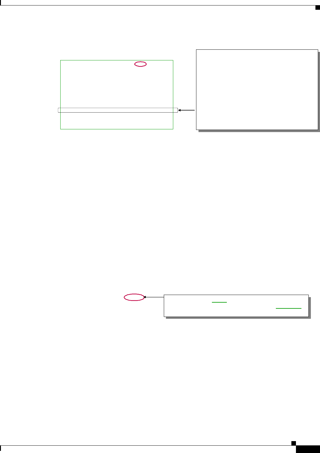
PRELIMINARY
7-33
BWX 8415 Basestation Installation and Commissioning Guide
OL-19519-01
Chapter 7 Commissioning
7.6.2 BWX 8415 Basestation Bootup
Example 7-6 Continuation of the Boot Process (NEED NEW BOOT SEQUENCE SCREENSHOTS)
Example 7-7 Completion of the Boot Process (NEED NEW BOOT SEQUENCE SCREENSHOTS)
When booting from the EMS you get this:
Selecting Config Data Source as EMS.......Done
Initializing NvRam Mib....................Done
Initializing SNMP Agent...................Done
EMS (192.168.2.208) Ping Attempt..........Done
Selecting Config Data Source as EMS.......Done
Initializing NvRam Mib....................Done
Initializing SNMP Agent...................Done
EMS (192.168.2.208) Ping Attempt..........Done
Requesting EMS for Configuration Data.....Done
Configuring BTS from EMS..................Done
Starting MMM..............................Done
Starting Sfm..............................Done
!!!!!!!! BTS Initialization Complete !!!!!!!!!
This step may take a few moments. If the BTS
fails to receive the configuration data from the
EMS (the line will say “Pending” instead of
“Done”), this step will timeout and the BTS will
request the configuration data data again. If
the BTS keeps trying and trying and still does
not get the data from the EMS (each iteration
may take 3 or 4 minutes), there is a
communication problem between the BTS and
the EMS. Check the Ethernet connections
and/or the EMS IP address under SystemÆ
General in the BTS Configuration record.
CCC CCC (TM)
CCC CCC
CCC CCC
CCC CCC CCC CCC CCC CCC
CCC CCC CCC CCC CCC CCC
CCC CCC CCC CCC CCC CCC
CCC CCC CCC CCC CCC CCC CCC CCC CCC
CCC CCC CCC CCC CCC CCC CCC CCC CCC
CCC CCC CCC CCC CCC CCC CCC CCC CCC
CCC CCC CCC CCC CCC CCC CCC CCC CCC P R O F I L E C
CCC CCC CCC CCC CCC CCC CCC CCC CCC
CCC CCC CCC CCC CCC CCC CCC CCC CCC
CCC CCC CCC CCC CCC CCC CCC CCC CCC
CCC CCC Copyright (c) Cisco Systems, Inc. 2008
CCC CCC Copyright (c) Texas Instruments, Inc. 2000-2001
CCC CCC Copyright (c) Wind River Systems, Inc. 1984-2002
### ##### #### ### ###
## ## ## ## ## ## ## ## ##
## ## ## ## ## ##
## ## ## ## ## ##
## ## ## ## ## ##
## ## ## ## ## ## ## ## ##
### ##### #### ### ###
S Y S T E M S
KERNEL : VxWorks5.5.1(WIND version 2.6)
BSP : 1.5RW7.0.2.9
CPU: Cisco Nero 7447A Power PC. Processor #0.
Memory Size: 0xfe00000.
WDB: Ready.
Reset Reason: S_RESET
Current time is WED OCT 22 14:27:22 2008 S_RESET means reboot from the console. Also possible
are UNKNOWN ("hard reset"), EMS_RESET (Reset BTS
from the EMS) and WATCHDOG (BTS rebooted by itself)
S_RESET means reboot from the console. Also possible
are UNKNOWN ("hard reset"), EMS_RESET (Reset BTS
from the EMS) and WATCHDOG (BTS rebooted by itself)
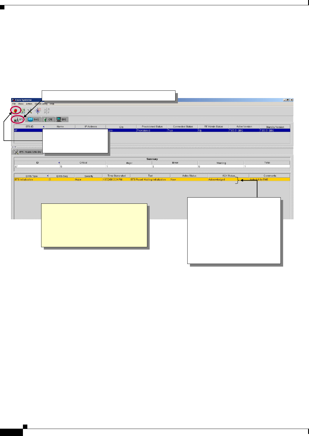
PRELIMINARY
7-34
BWX 8415 Basestation Installation and Commissioning Guide
OL-19519-01
Chapter 7 Commissioning
7.6.2 BWX 8415 Basestation Bootup
7.6.2.2 Check for Alarms
To check the EMS CAM for alarms, follow the instructions in Figure 7-38. All alarms must first be
acknowledged, then cleared. Refer to the BWX EMS Alarm Resolution Reference Manual for look-up
descriptions and resolutions for each alarm.
Figure 7-38 Check Alarms
Refer to Figure 7-39 for the Alarm Severity indicators.
1. Select BTS tab, then select one or more BTSs
1. Select BTS tab, then select one or more BTSs
2. Click on the
Alarm Icon to see
the BTS Alarms
2. Click on the
Alarm Icon to see
the BTS Alarms
A few alarms will appear and
will be automatically cleared
during the BTS boot.
Once an alarm is "cleared" and
"acknowledged", it disappears.
If an alarm is not automatically
acknowledged you can
acknowledge it manually to
make it go away.
A few alarms will appear and
will be automatically cleared
during the BTS boot.
Once an alarm is "cleared" and
"acknowledged", it disappears.
If an alarm is not automatically
acknowledged you can
acknowledge it manually to
make it go away.
This is an alternative to viewing
the outstanding BTS alarms by
entering the ShowAlarms
command at the "console"
(terminal emulation) window
This is an alternative to viewing
the outstanding BTS alarms by
entering the ShowAlarms
command at the "console"
(terminal emulation) window
1. Select BTS tab, then select one or more BTSs
1. Select BTS tab, then select one or more BTSs
2. Click on the
Alarm Icon to see
the BTS Alarms
2. Click on the
Alarm Icon to see
the BTS Alarms
A few alarms will appear and
will be automatically cleared
during the BTS boot.
Once an alarm is "cleared" and
"acknowledged", it disappears.
If an alarm is not automatically
acknowledged you can
acknowledge it manually to
make it go away.
A few alarms will appear and
will be automatically cleared
during the BTS boot.
Once an alarm is "cleared" and
"acknowledged", it disappears.
If an alarm is not automatically
acknowledged you can
acknowledge it manually to
make it go away.
This is an alternative to viewing
the outstanding BTS alarms by
entering the ShowAlarms
command at the "console"
(terminal emulation) window
This is an alternative to viewing
the outstanding BTS alarms by
entering the ShowAlarms
command at the "console"
(terminal emulation) window
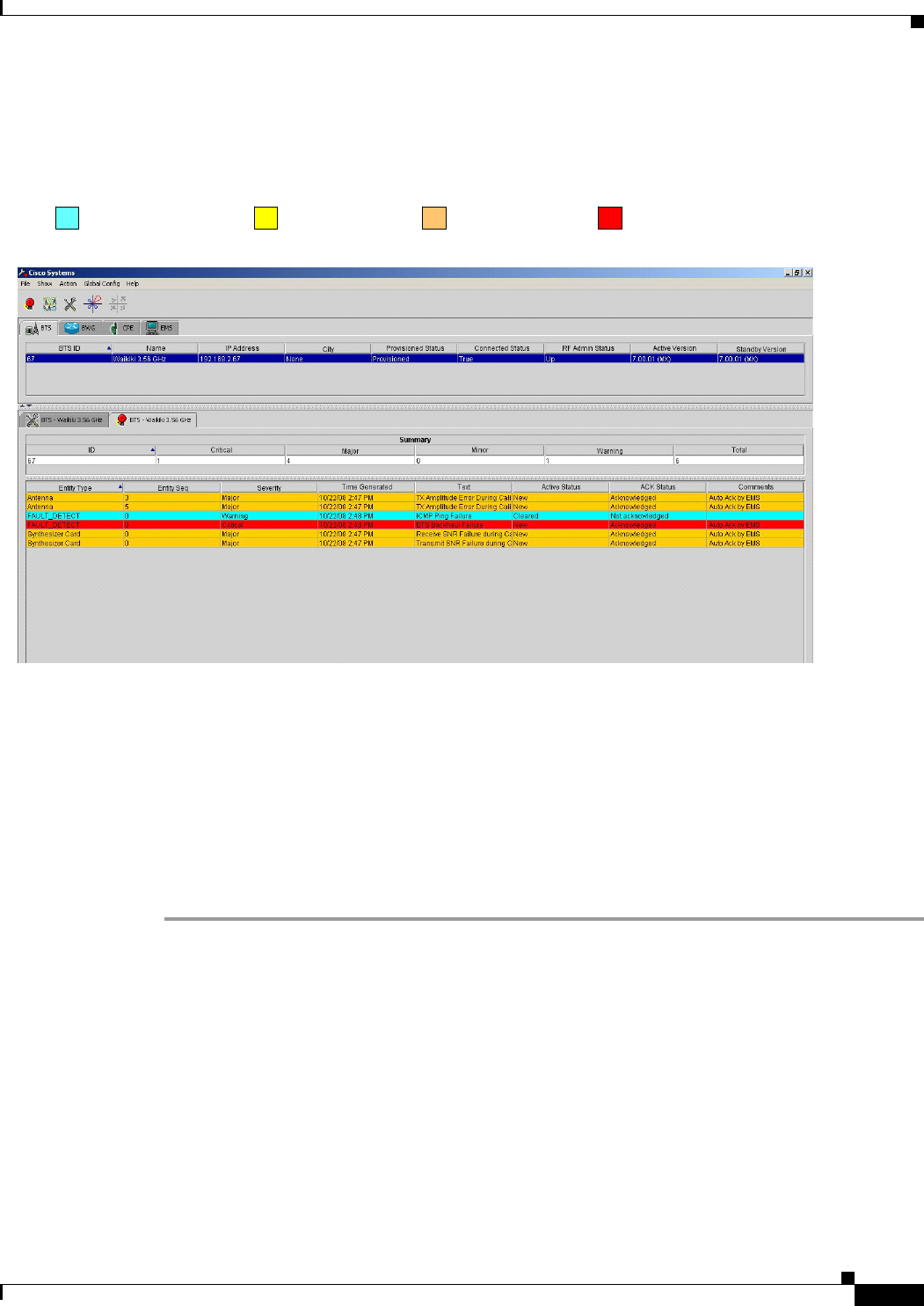
PRELIMINARY
7-35
BWX 8415 Basestation Installation and Commissioning Guide
OL-19519-01
Chapter 7 Commissioning
7.6.3 Provision the BWX 8415 Basestation
Figure 7-39 Alarm Severity Indicators
7.6.3 Provision the BWX 8415 Basestation
When all of the basic BS configuration is completed, the BS needs to be provisioned. If the BS is
“provisioned”, then any change to the record immediately affects the BS. If “unprovisioned”, you can
change the record without affecting the BS. Certain actions (like “Calibrate”) require that the BS be
“provisioned”.
The steps to provision the BS are shown in Figure 7-24 through Figure 7-29. Please refer to these figures
as you read the remainder of this section.
Step 1 From the BTS tab, right-click on the BS which is to be provisioned.
Step 2 In the pull-down select Action > Provision to make that record active for the new BS.
Severity indicators
1 – Warning 2 – Minor 3 – Major 4 - Critical
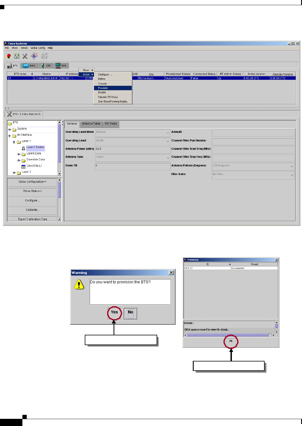
PRELIMINARY
7-36
BWX 8415 Basestation Installation and Commissioning Guide
OL-19519-01
Chapter 7 Commissioning
7.6.3 Provision the BWX 8415 Basestation
Figure 7-40 Provisioning the BWX 8415 Basestation
Step 3 Click on Yes in the warning box and click Ok to continue.
Figure 7-41 Provisioning Warning
Click on “Yes”to continue.
Click on “Ok” to continue.Click on “Ok” to continue.Click on “Ok” to continue.
Click on “Yes”to continue.
Click on “Ok” to continue.Click on “Ok” to continue.Click on “Ok” to continue.Click on “Ok” to continue.Click on “Ok” to continue.Click on “Ok” to continue.