Cisco Systems 2484-B8415-R1 WiMAX Base Station, Broadband Wireless, 2.5/2.6 GHz User Manual Installation manual Part 3
Cisco Systems, Inc WiMAX Base Station, Broadband Wireless, 2.5/2.6 GHz Installation manual Part 3
Contents
- 1. Installation manual Part 1
- 2. Installation manual Part 2
- 3. Installation manual Part 3
- 4. Installation manual Part 4
- 5. Installation manual Part 5
Installation manual Part 3

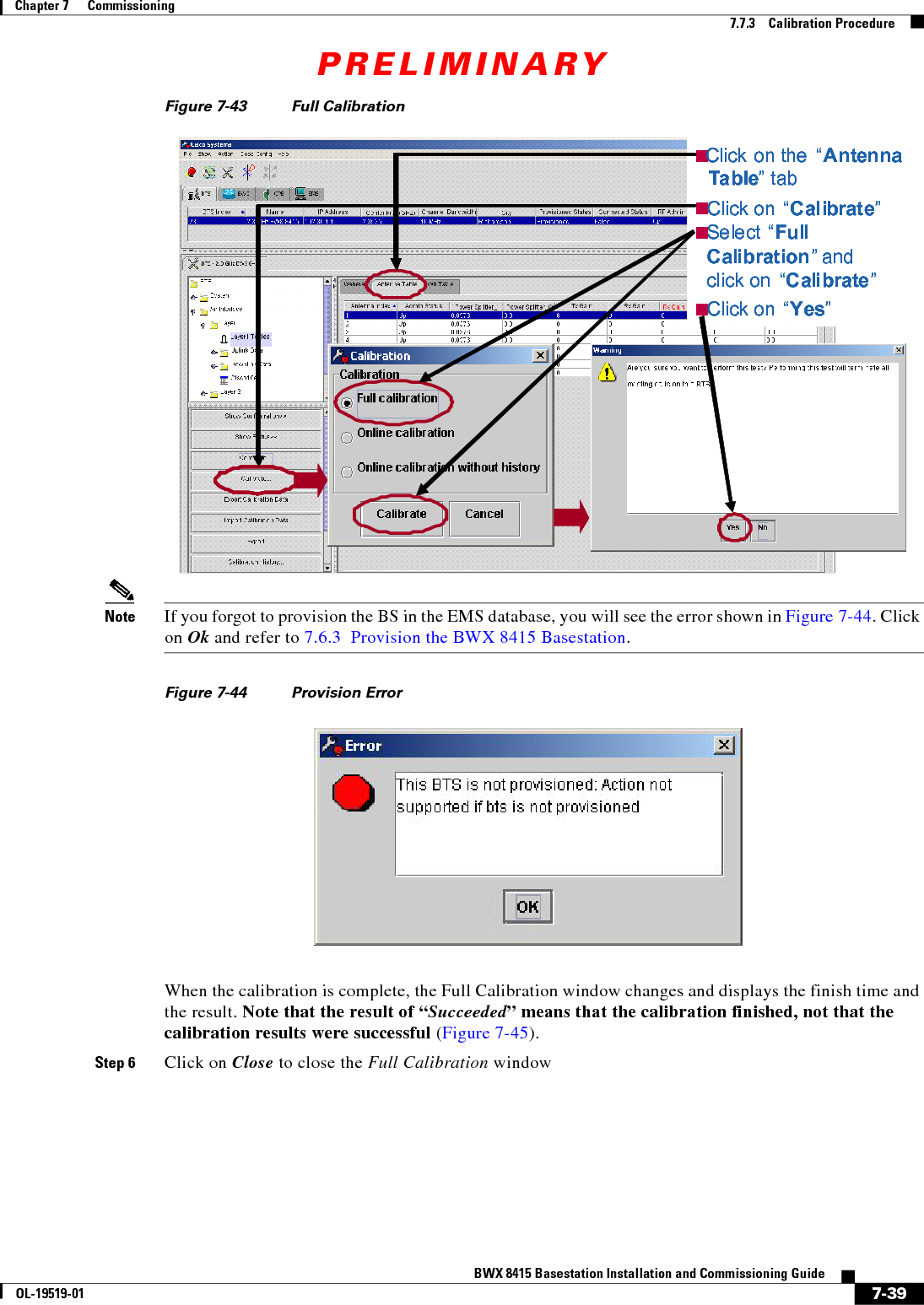
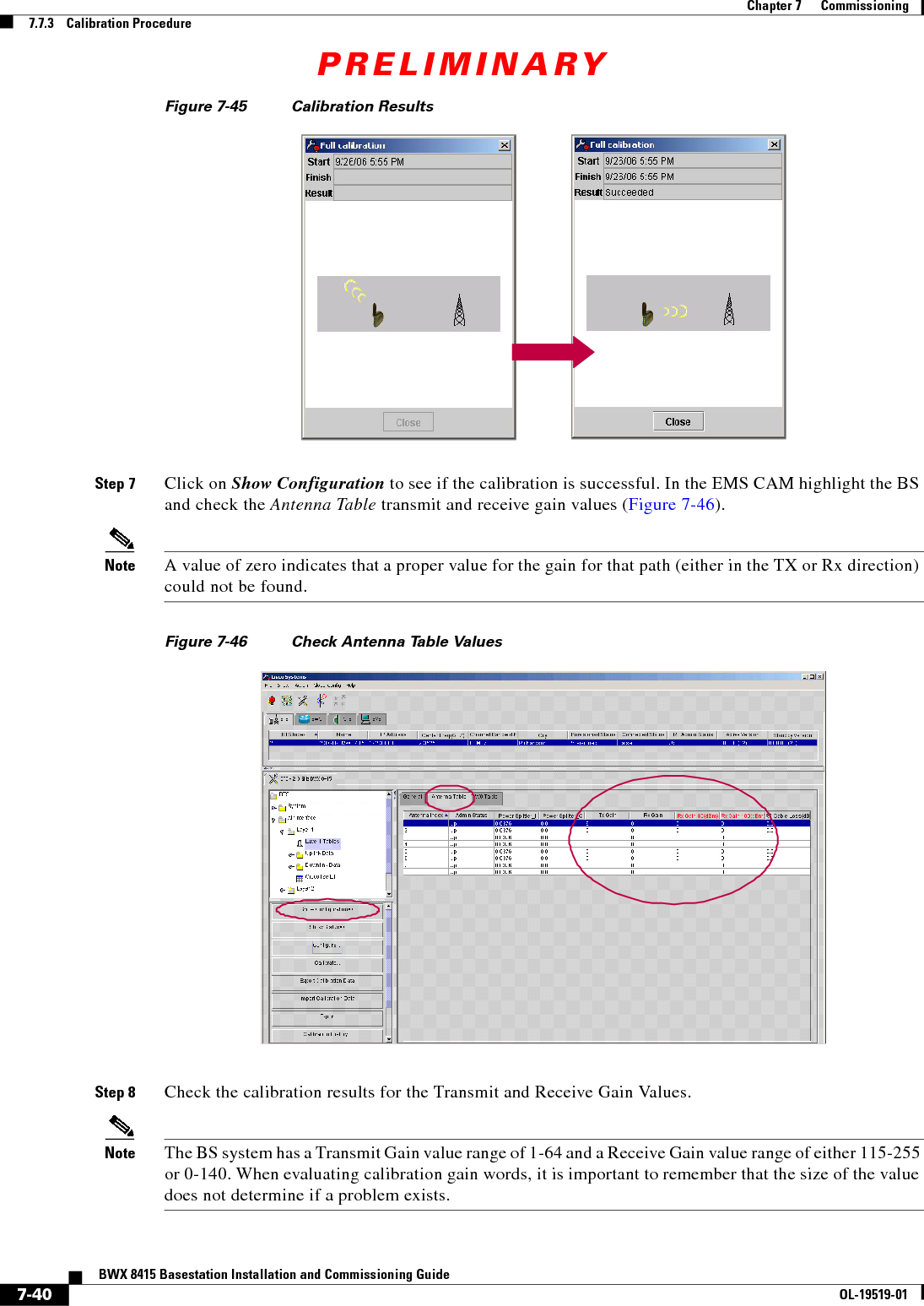
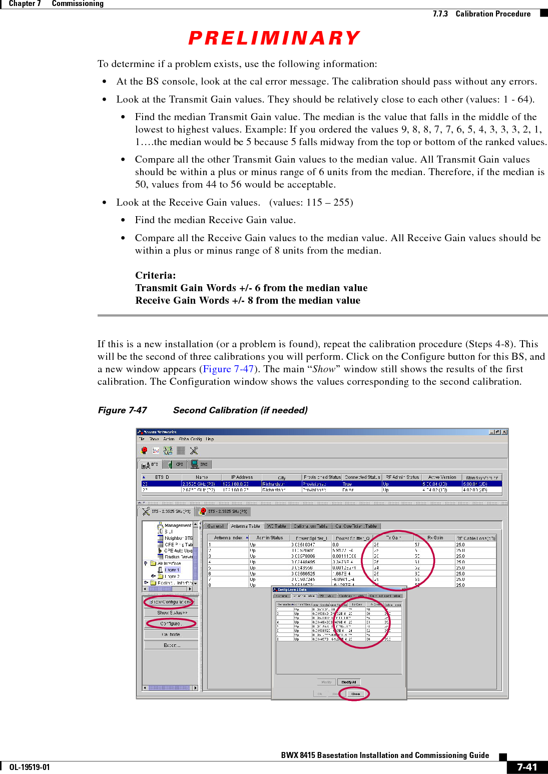
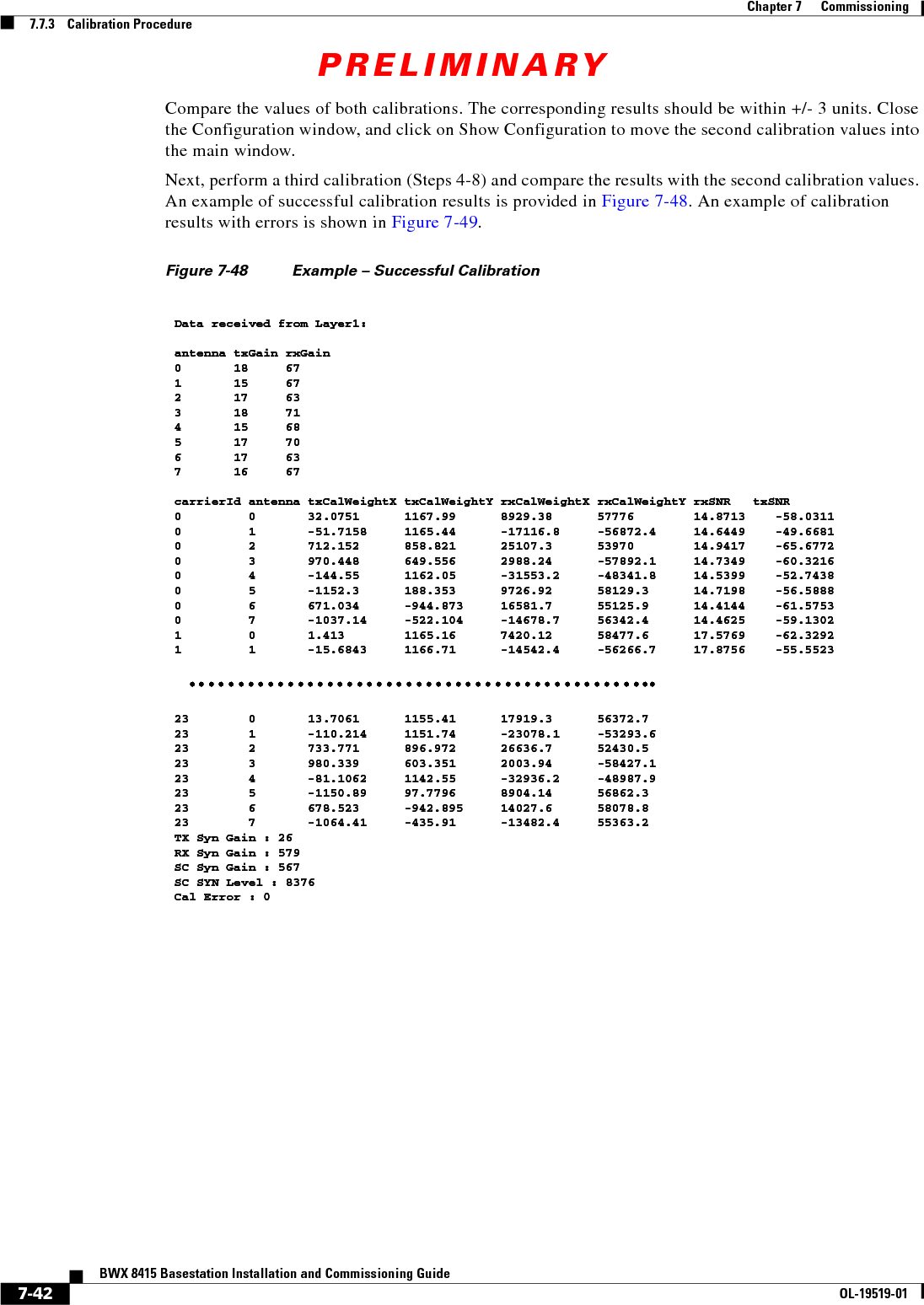
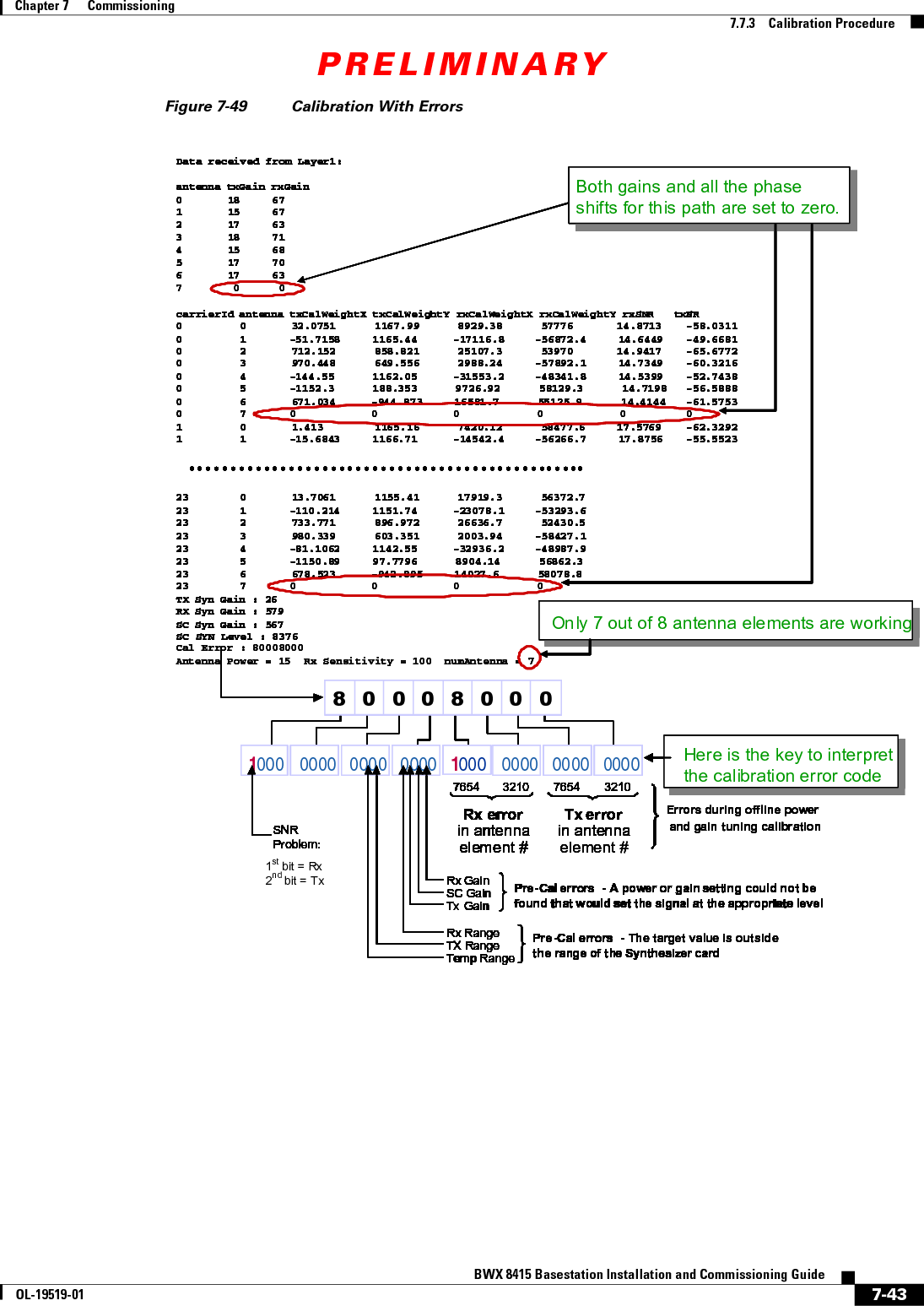
![PRELIMINARY7-38BWX 8415 Basestation Installation and Commissioning GuideOL-19519-01Chapter 7 Commissioning7.7.3 Calibration ProcedureWhen the BS is calibrated, the measured values are stored in the BS and then reported to the EMS to be stored under Air Interface > Layer 1. The Digital card pre-calibration values are placed in the General tab. The TX and RX gain values are placed in the Antenna Table.7.7.3 Calibration ProcedureBefore you can calibrate, ensure the following requirements are met: • The BS must have been previously added and configured in the EMS database • The BS must be powered up for at least 15 minutes, booted properly, stable (not resetting) and all alarms cleared before running the calibration • Select the BS on the EMS CAM by clicking on the BSNote The BS must be provisioned before you can calibrate. If the BS is not provisioned, refer to 7.6.3 Provision the BWX 8415 Basestation for the steps to perform the provisioning.Step 1 Select Air Interface > Layer 1 > Layer 1 Tables.Step 2 Click on Show Configuration.Step 3 From a terminal emulation program type in the command, caldebugon and hit <Enter> (Figure 7-42).Figure 7-42 Show ConfigurationStep 4 With the Antenna Table tab selected, click on CalibrateStep 5 Select Full Calibration and Calibrate and then click on Yes . Refer to Figure 7-43. bts-221 [Active]% caldebugonbts221 [Active]%Make sure you type "caldebugof fwhen you are done with the calibration!!!Terminal Emulation Programbts-221 [Active]% caldebugonbts221 [Active]%Make sure you type "caldebugof fwhen you are done with the calibration!!!Terminal Emulation Programbts-221 [Active]% caldebugonbts221 [Active]%Make sure you type "caldebugof fwhen you are done with the calibration!!!Terminal Emulation Programbts-221 [Active]% caldebugonbts221 [Active]%Make sure you type "caldebugof fwhen you are done with the calibration!!!Terminal Emulation Programbts-221 [Active]% caldebugonbts221 [Active]%Make sure you type "caldebugof fwhen you are done with the calibration!!!Terminal Emulation Programbts-221 [Active]% caldebugonbts221 [Active]%Make sure you type "caldebugof fwhen you are done with the calibration!!!Terminal Emulation Programbts-221 [Active]% caldebugonbts221 [Active]%Make sure you type "caldebugof fwhen you are done with the calibration!!!Terminal Emulation Programbts-221 [Active]% caldebugonbts221 [Active]%Make sure you type "caldebugof fwhen you are done with the calibration!!!Terminal Emulation Programbts-221 [Active]% caldebugonbts221 [Active]%Make sure you type "caldebugof fwhen you are done with the calibration!!!Terminal Emulation Programbts-221 [Active]% caldebugonbts221 [Active]%Make sure you type "caldebugof fwhen you are done with the calibration!!!Terminal Emulation Programbts-221 [Active]% caldebugonbts221 [Active]%Make sure you type "caldebugof fwhen you are done with the calibration!!!Terminal Emulation Programbts-221 [Active]% caldebugonbts221 [Active]%Make sure you type "caldebugof fwhen you are done with the calibration!!!Terminal Emulation Programbts-221 [Active]% caldebugonbts221 [Active]%Make sure you type "caldebugof fwhen you are done with the calibration!!!Terminal Emulation Programbts-221 [Active]% caldebugonbts221 [Active]%Make sure you type "caldebugof fwhen you are done with the calibration!!!Terminal Emulation Programbts-221 [Active]% caldebugonbts221 [Active]%Make sure you type "caldebugof fwhen you are done with the calibration!!!Terminal Emulation Programbts-221 [Active]% caldebugonbts221 [Active]%Make sure you type "caldebugof fwhen you are done with the calibration!!!Terminal Emulation Program](https://usermanual.wiki/Cisco-Systems/2484-B8415-R1.Installation-manual-Part-3/User-Guide-1234010-Page-10.png)