Cisco Systems ALTMT0556 Utility Meter Monitoring System User Manual cgr1240hig
Cisco Systems Inc Utility Meter Monitoring System cgr1240hig
Contents
- 1. user manual pt 1
- 2. 3G module manual
- 3. 900 MHz module manual
- 4. user manual pt 2
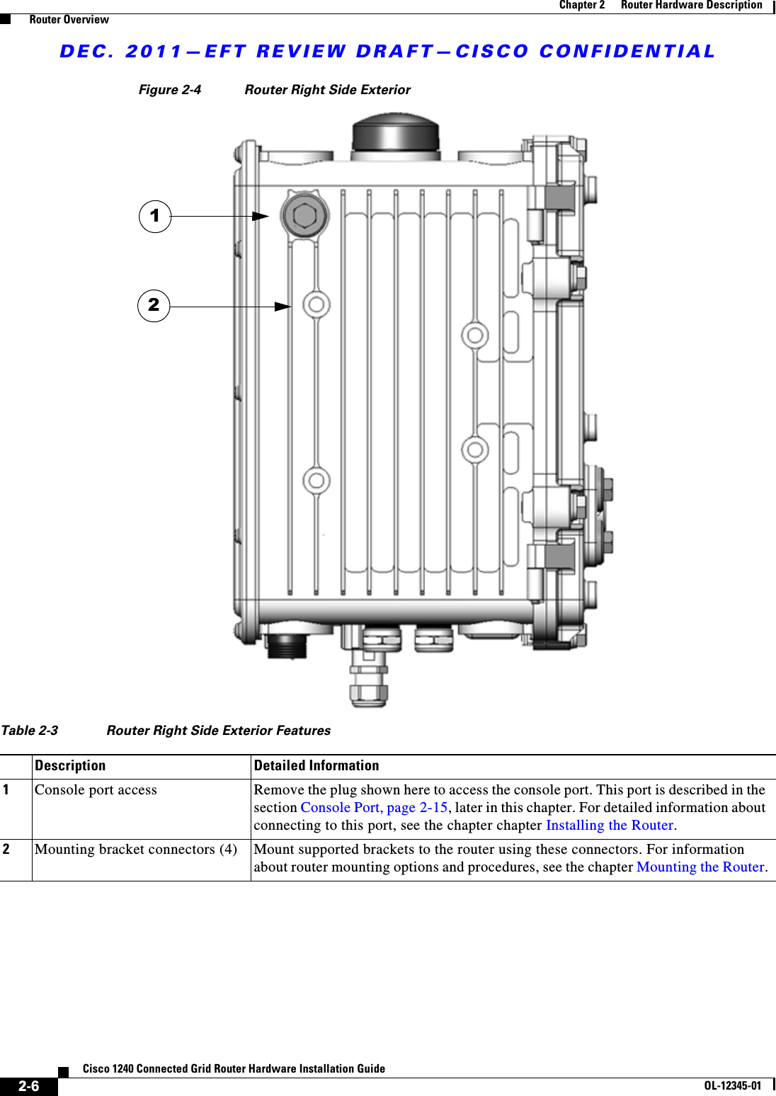
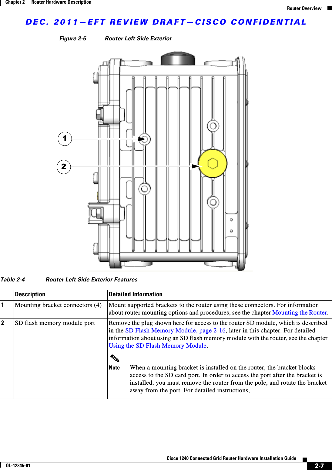
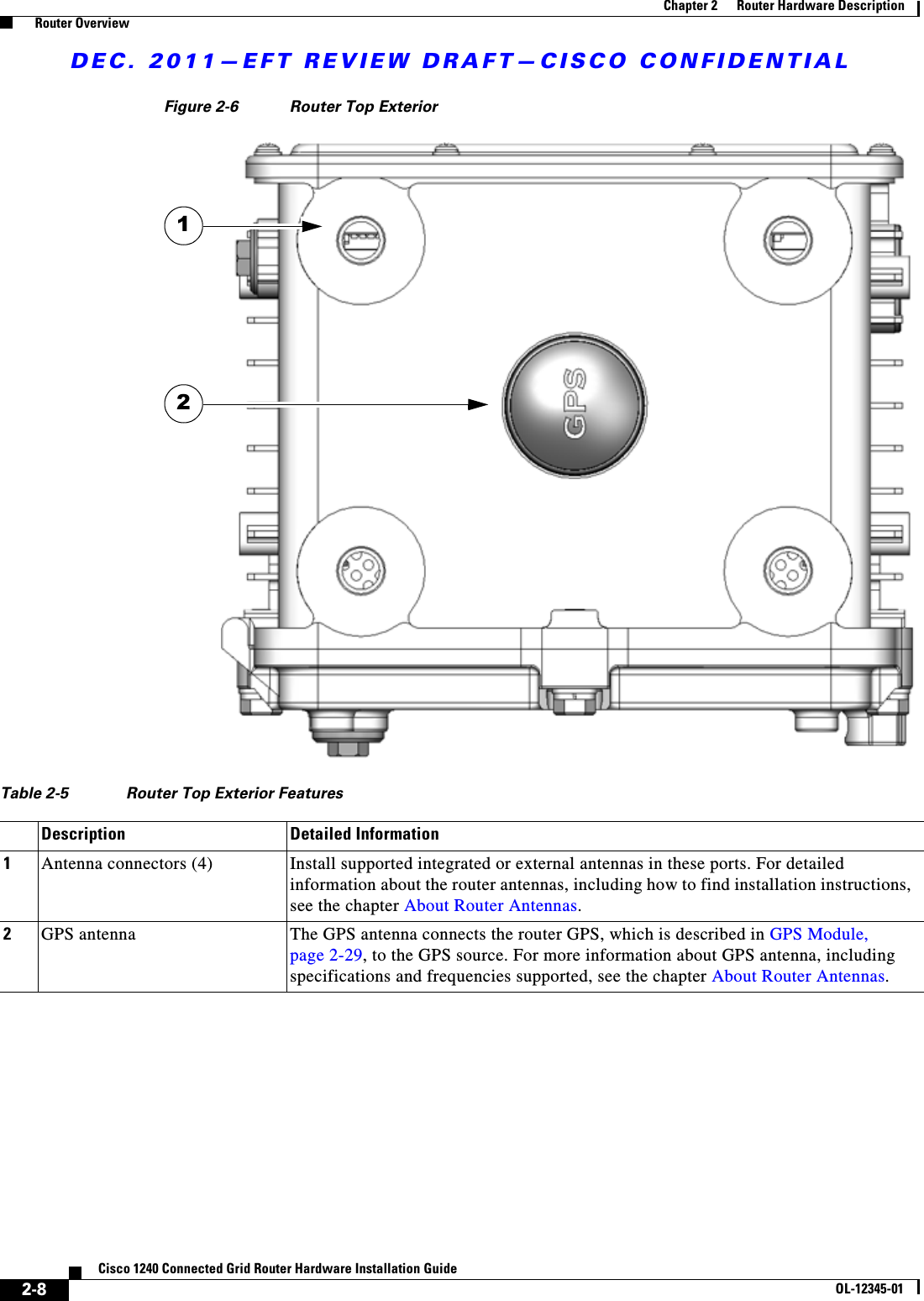
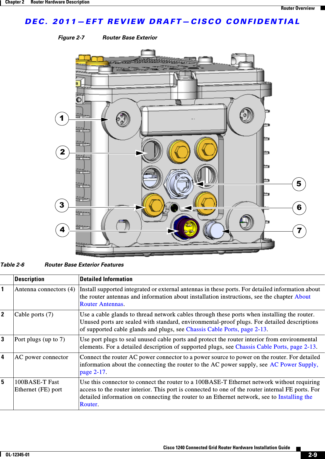
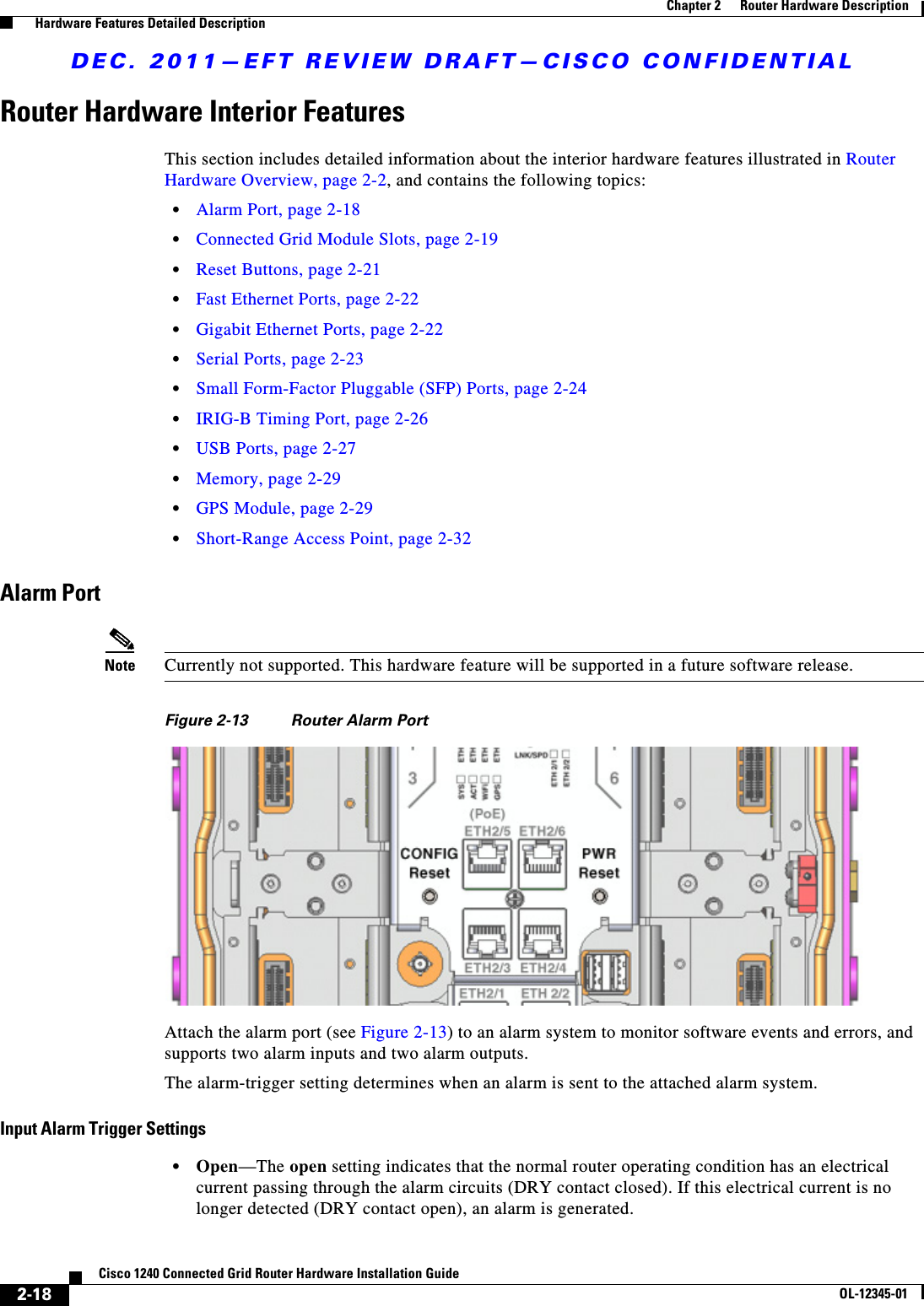
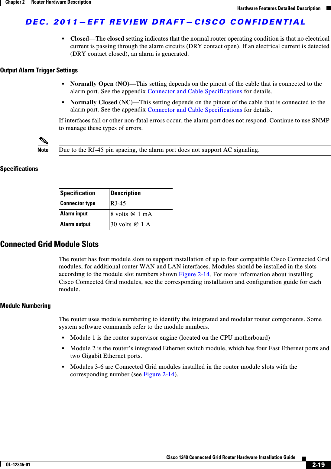
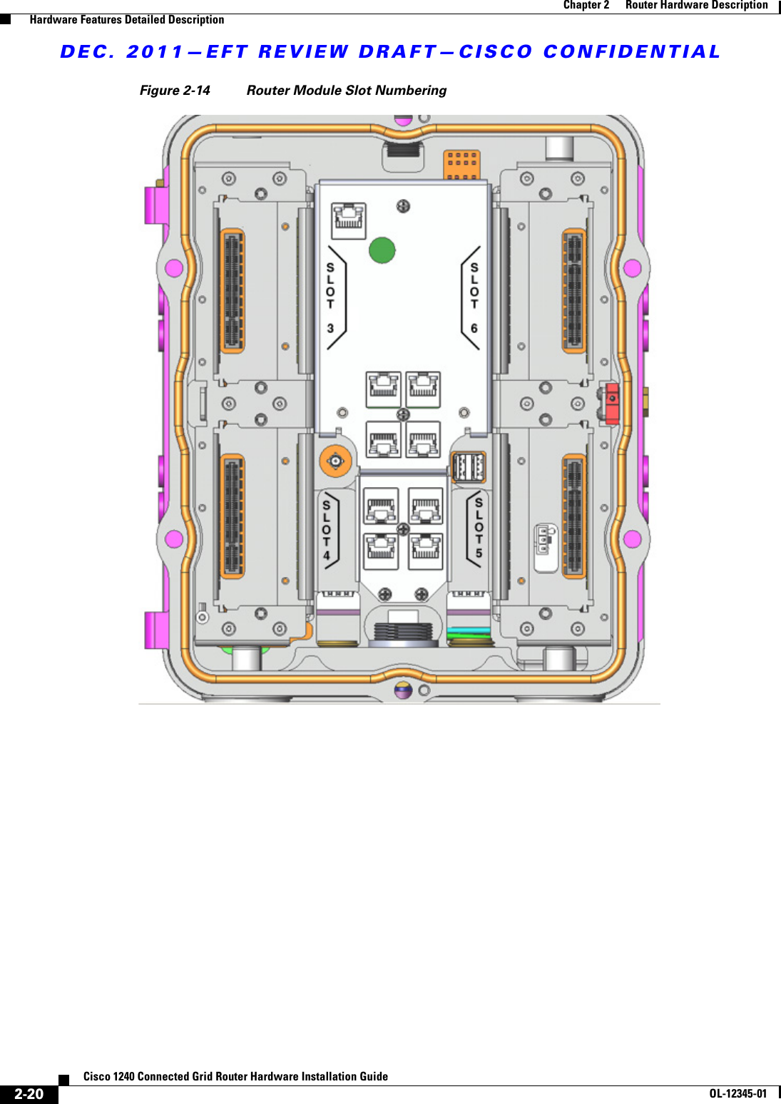
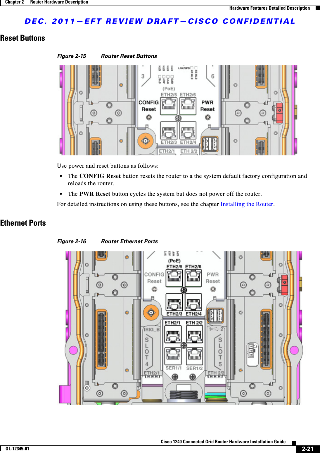
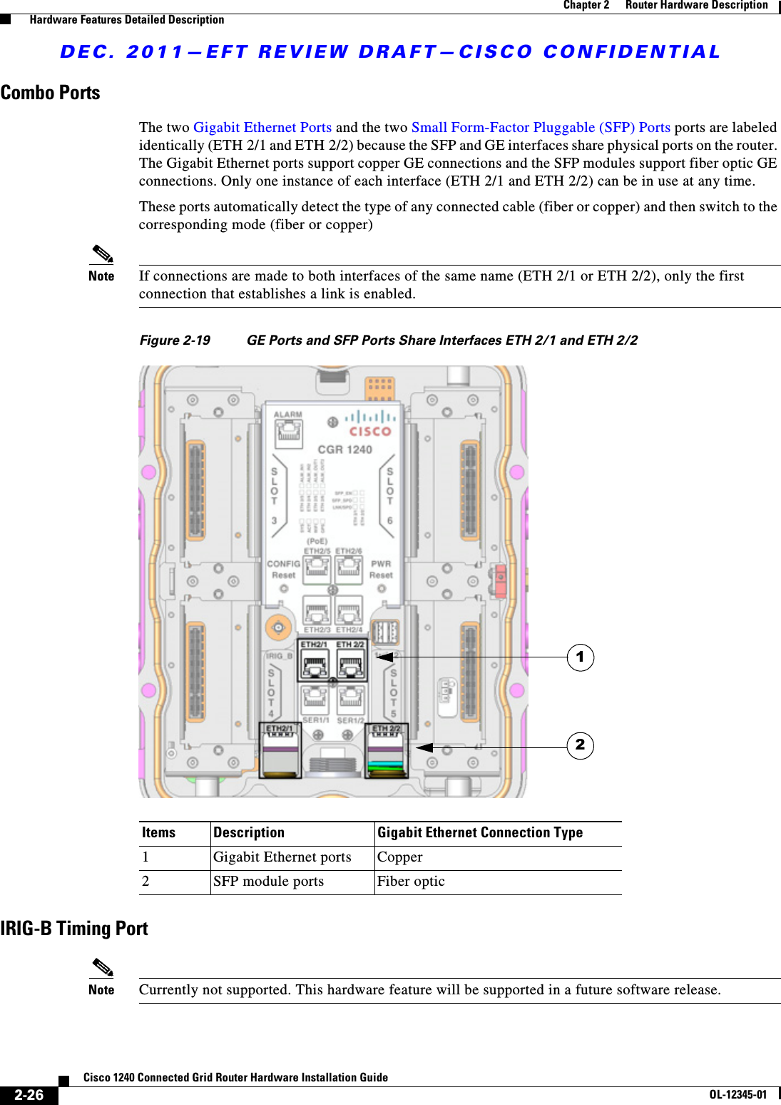
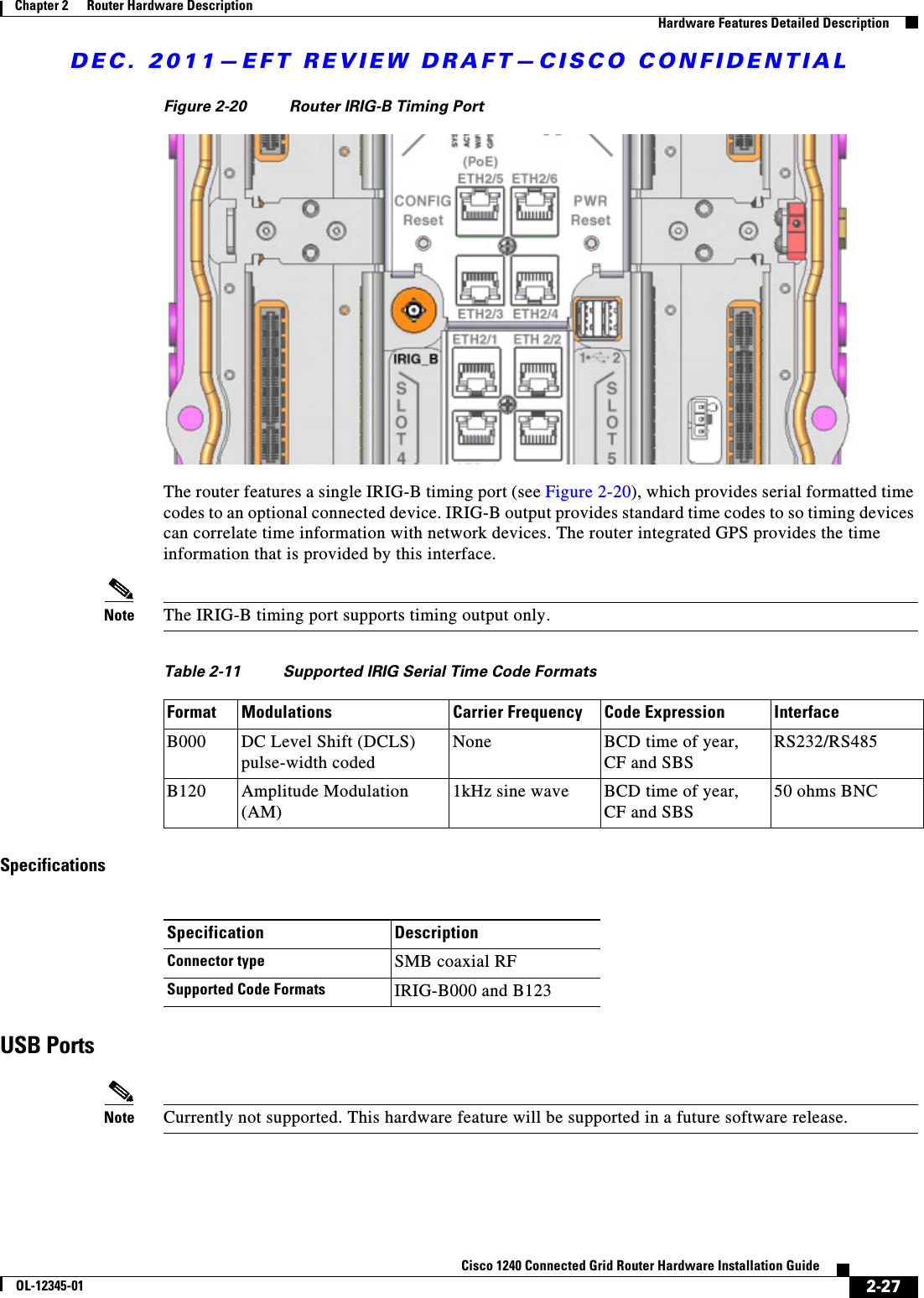
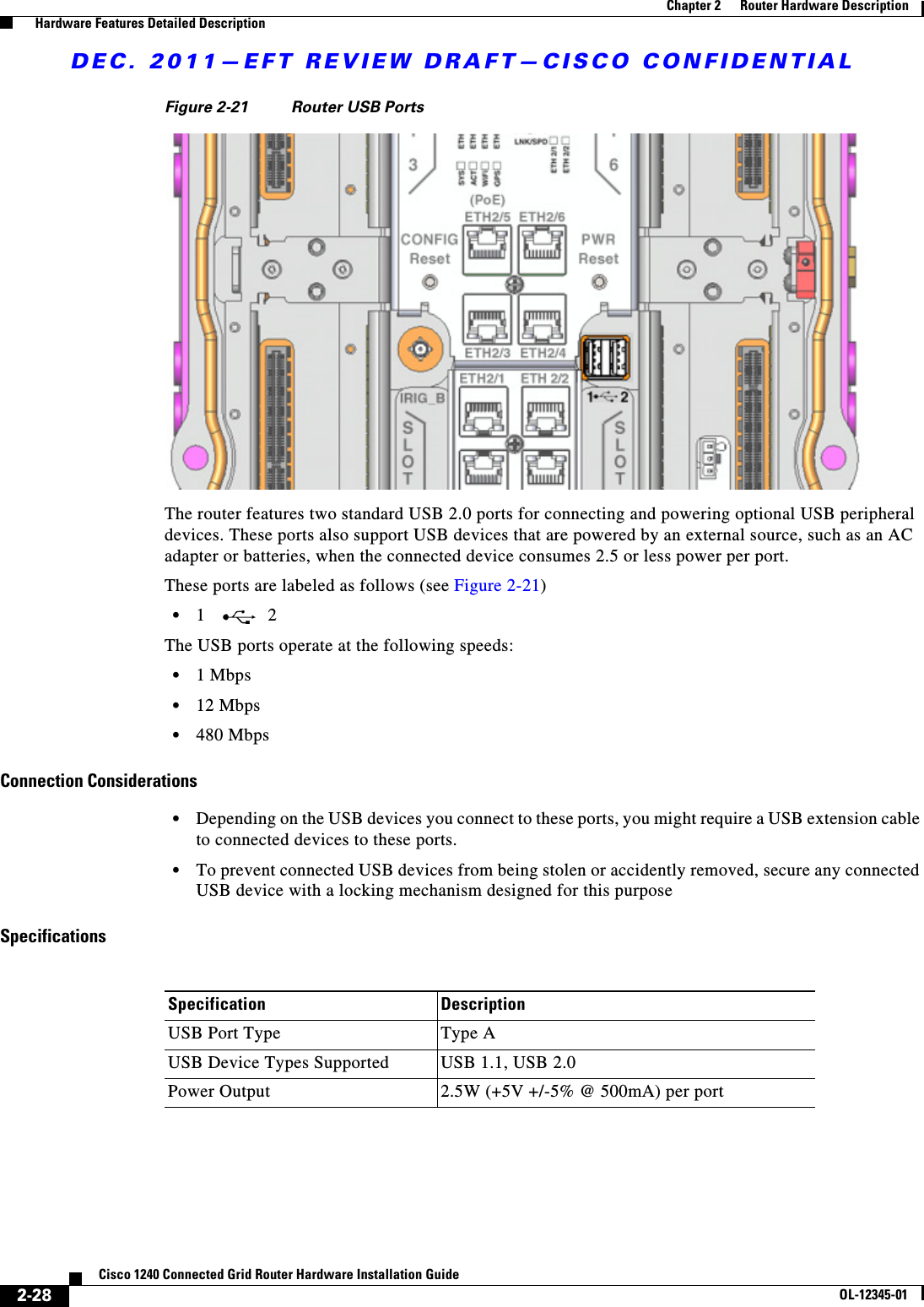
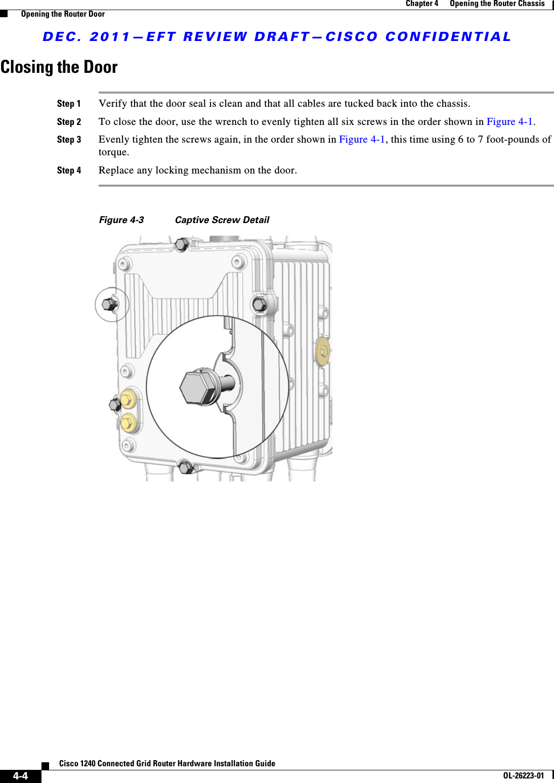
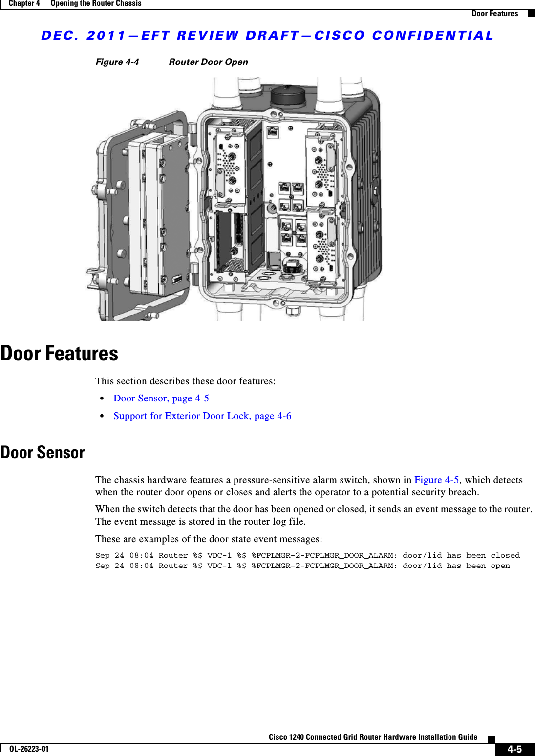
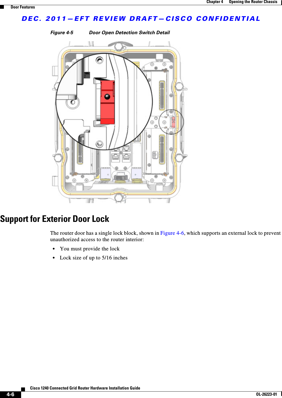
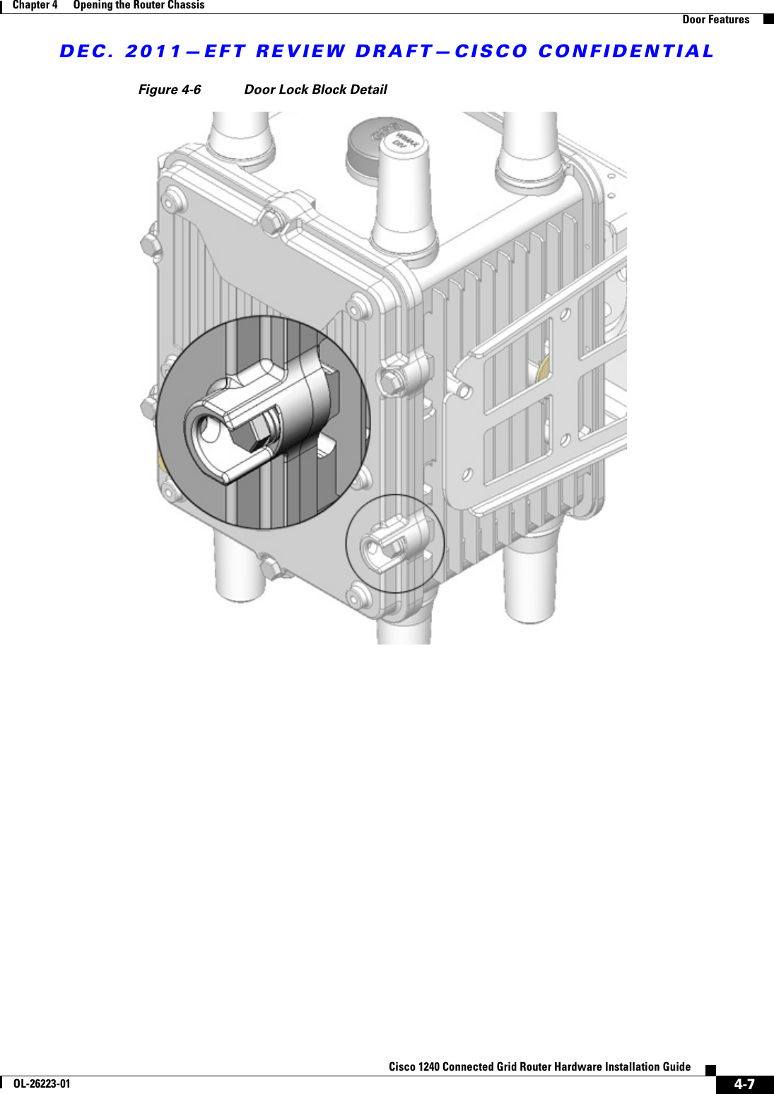
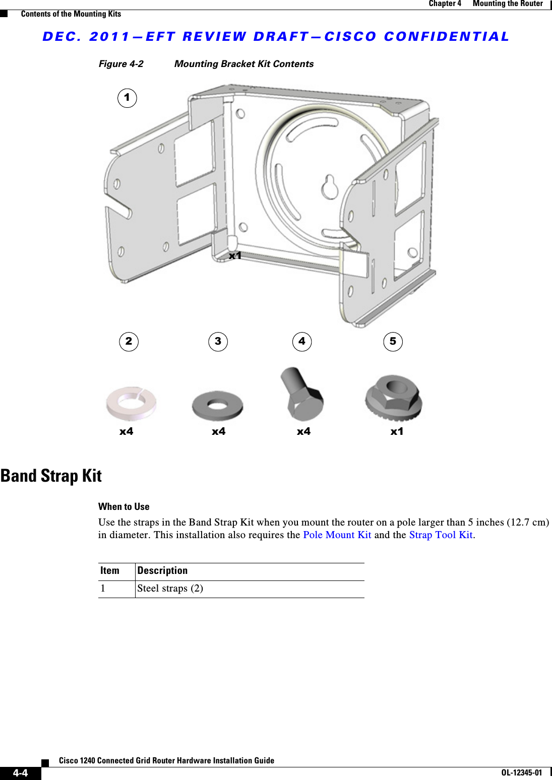
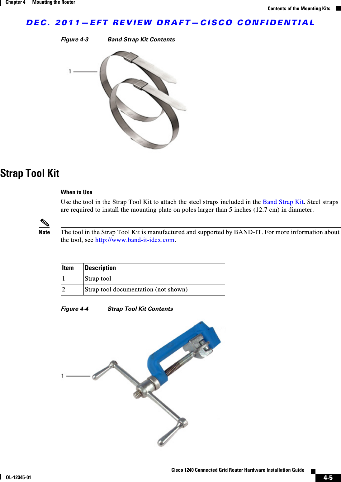
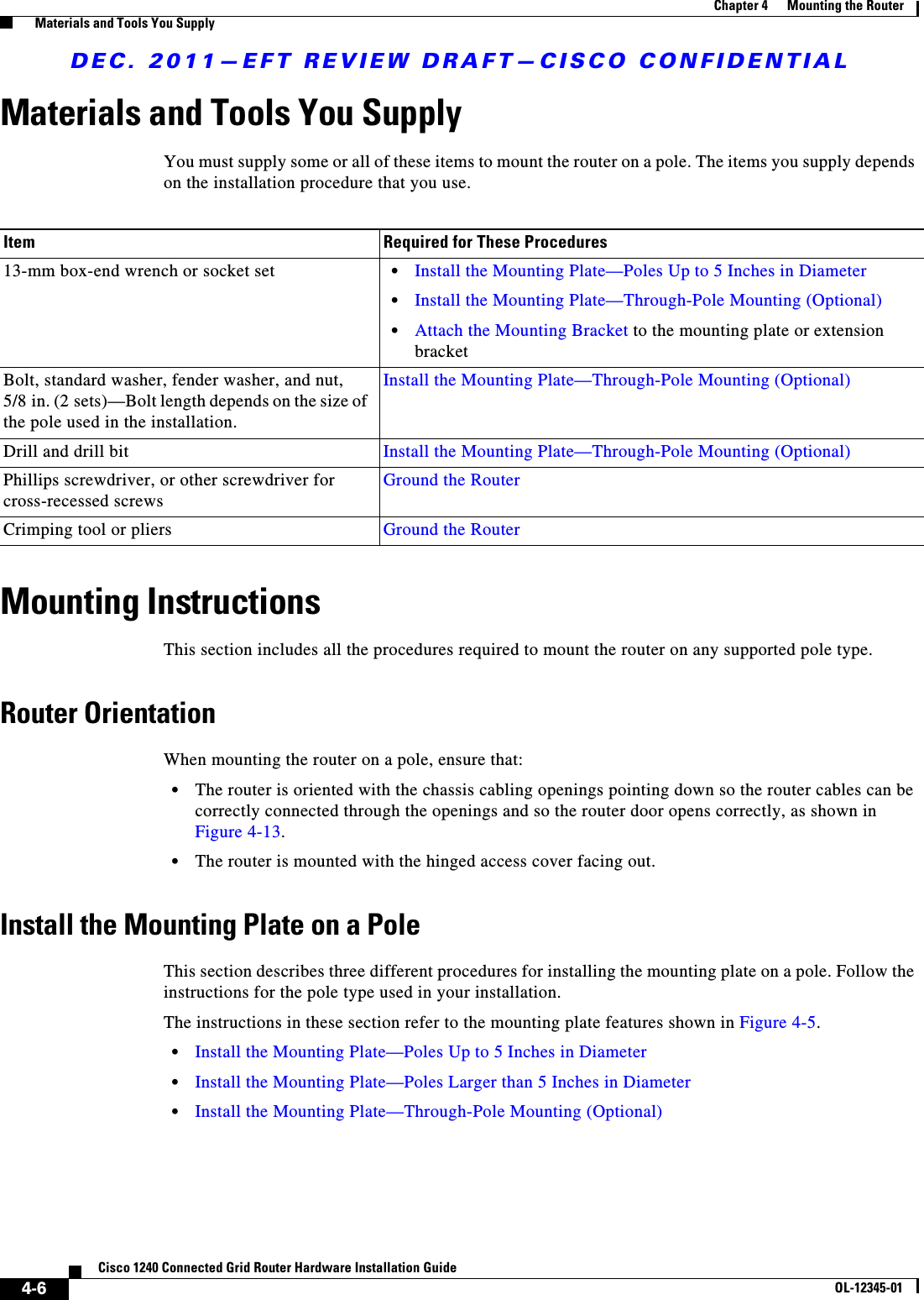
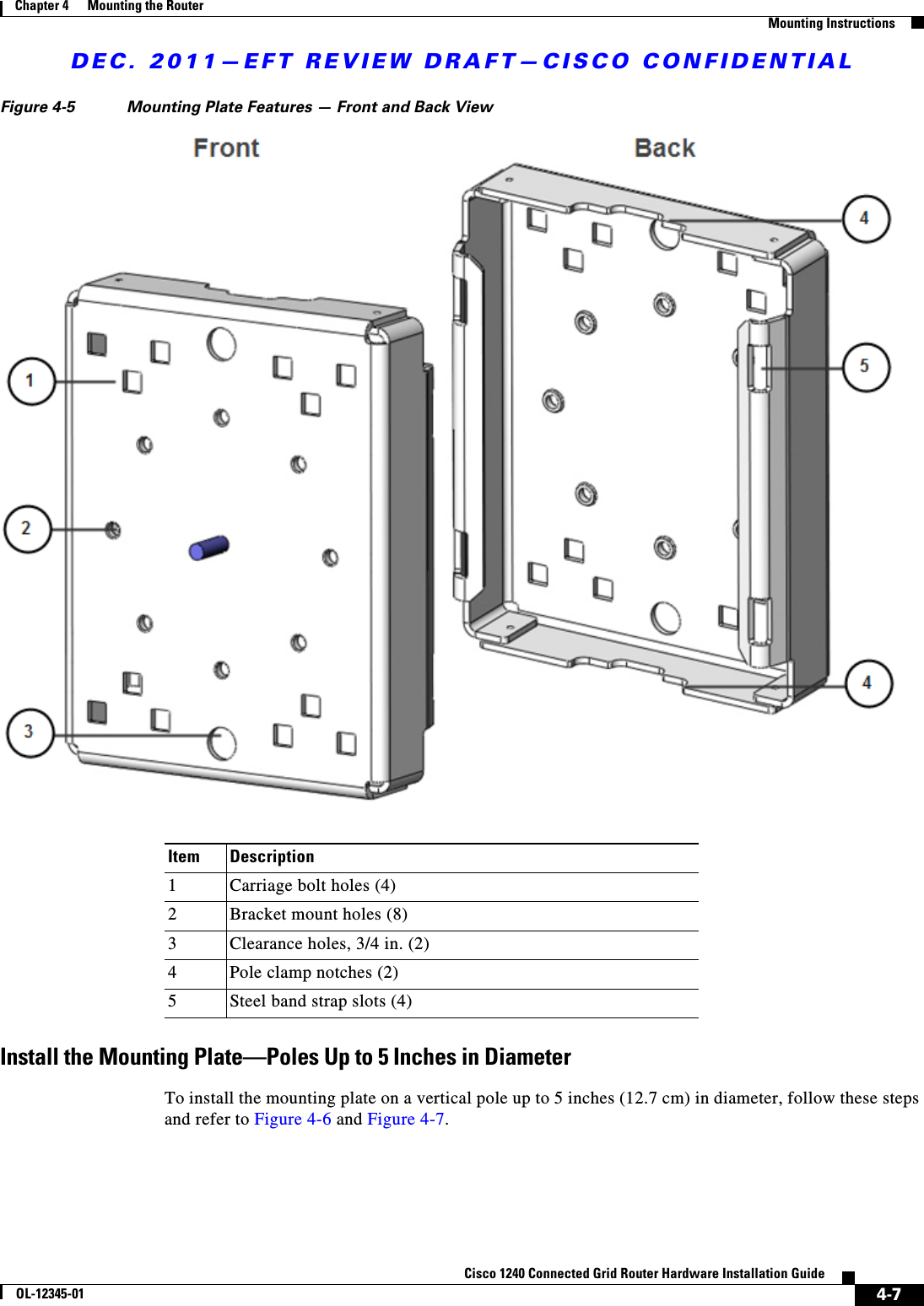
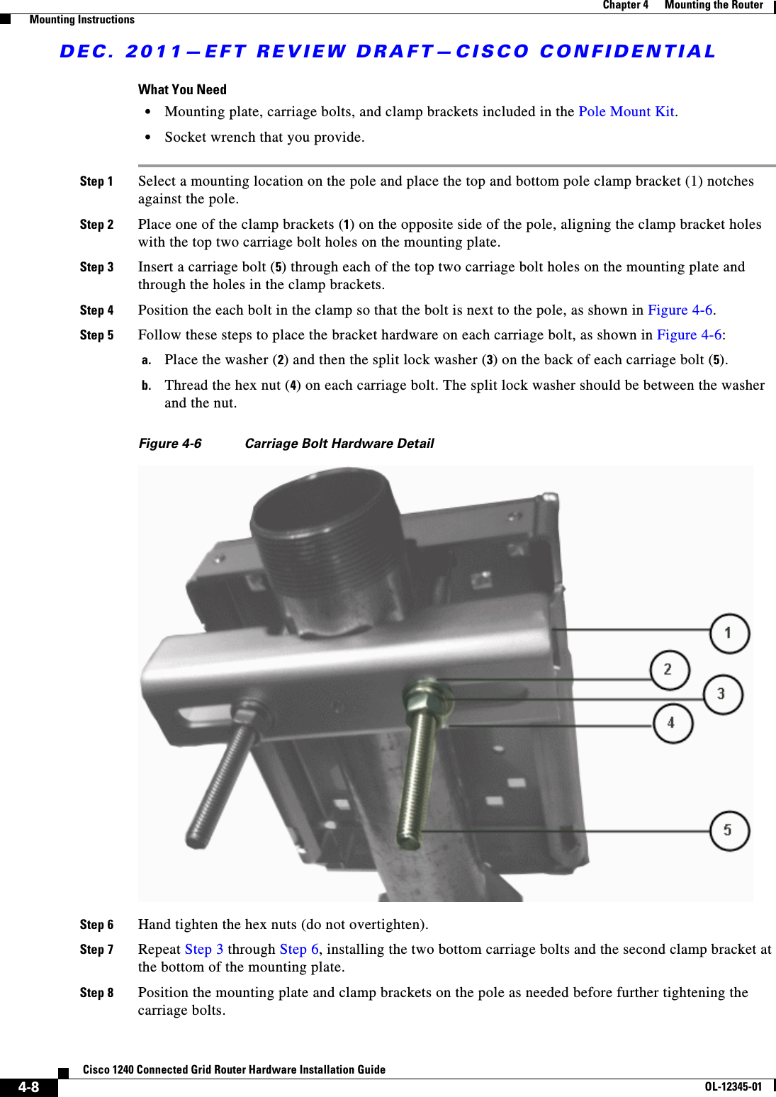
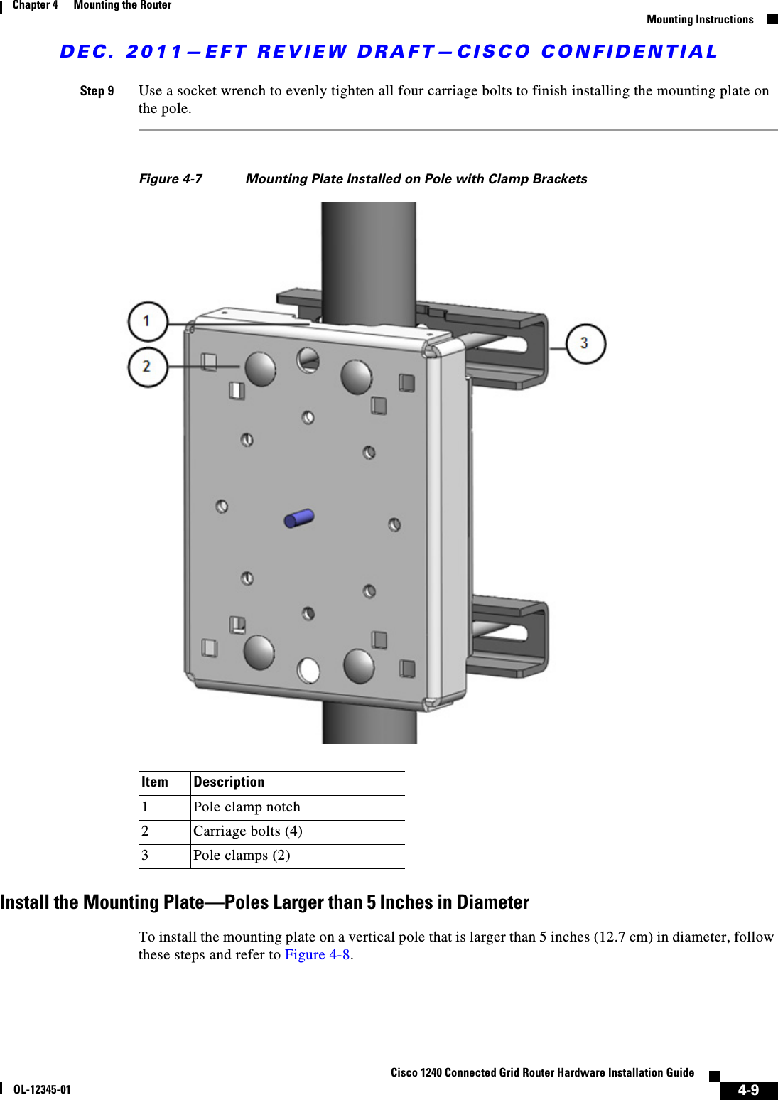
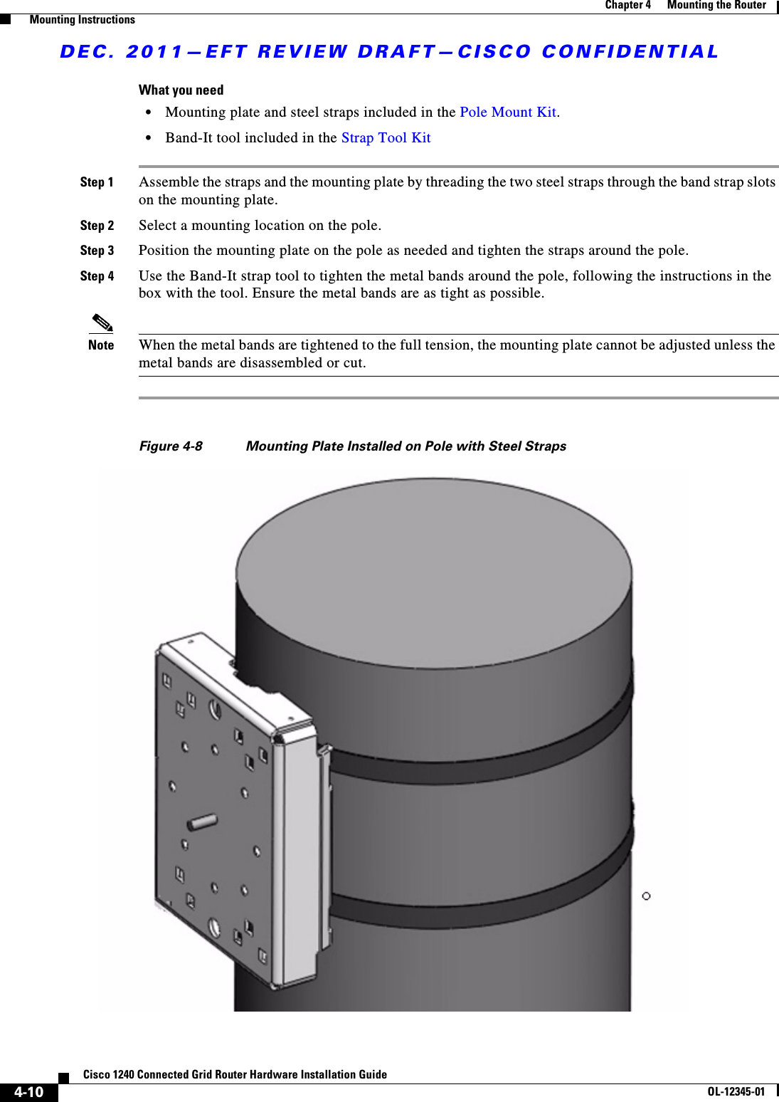
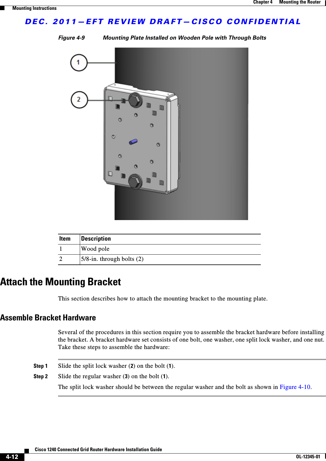
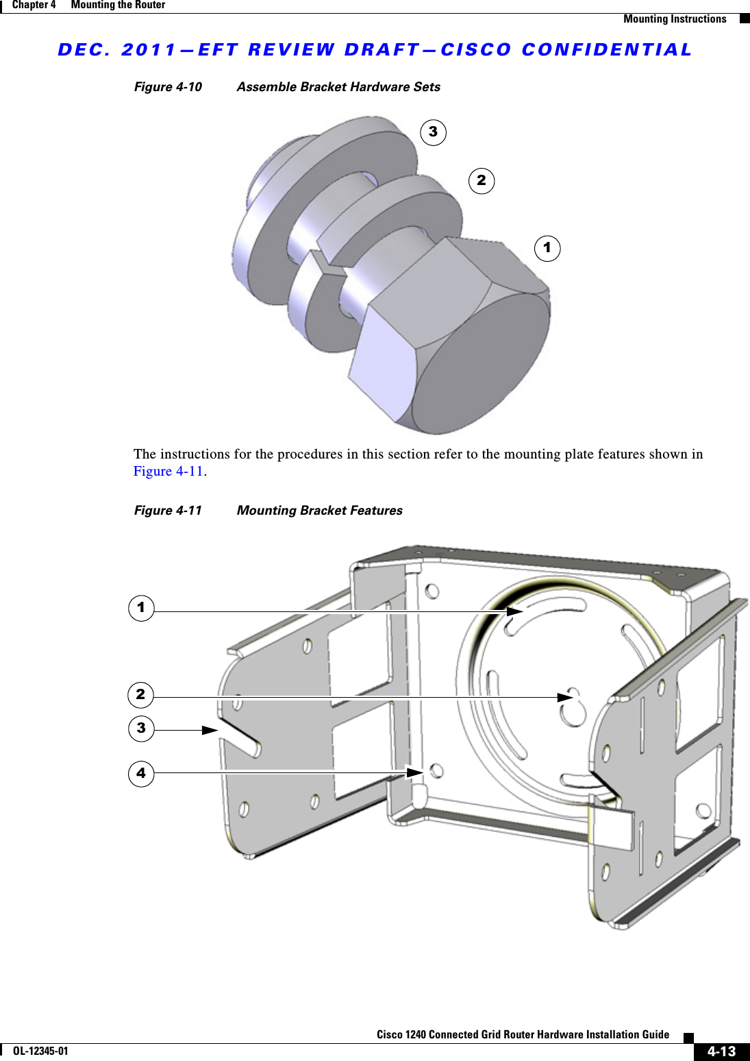
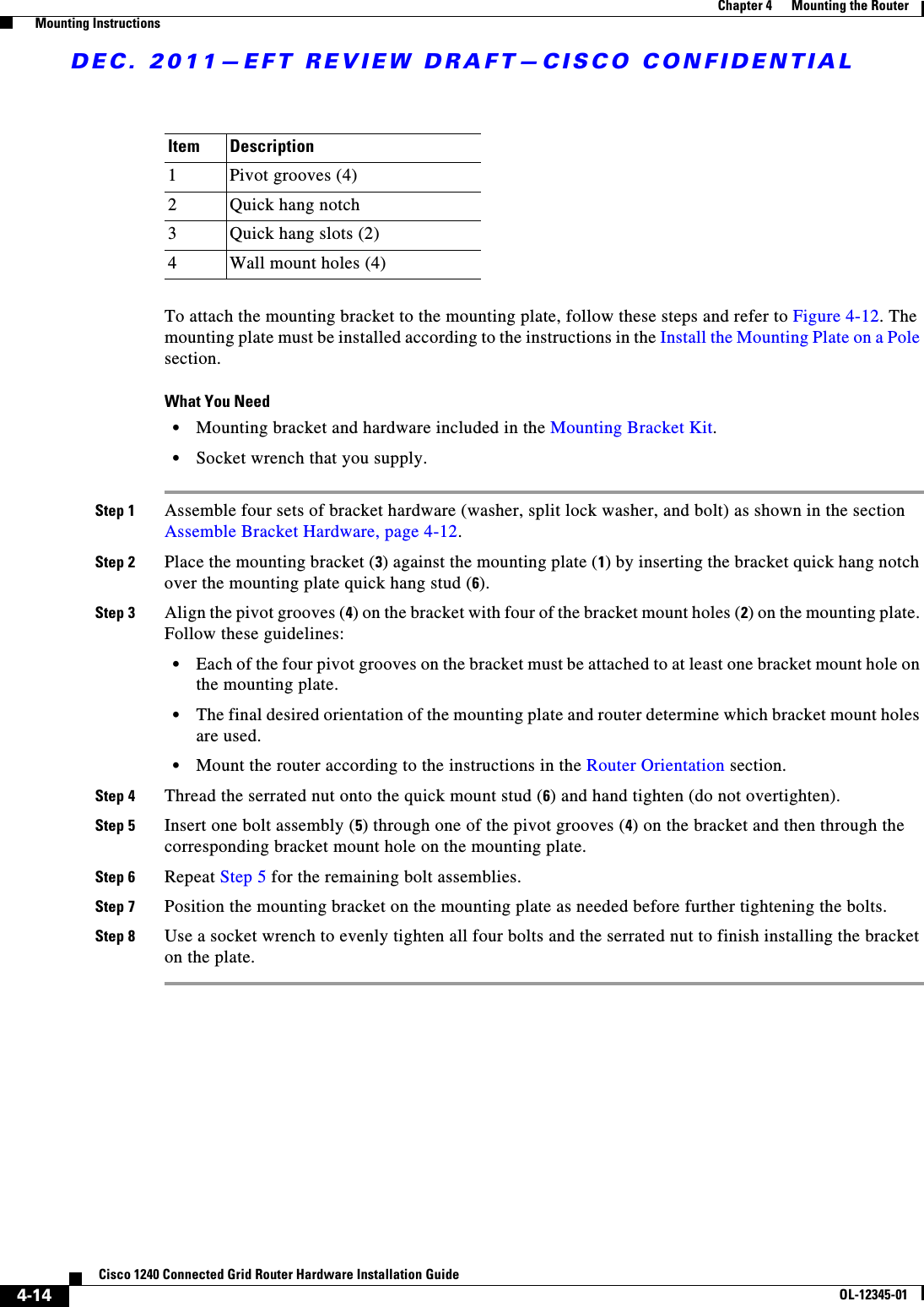
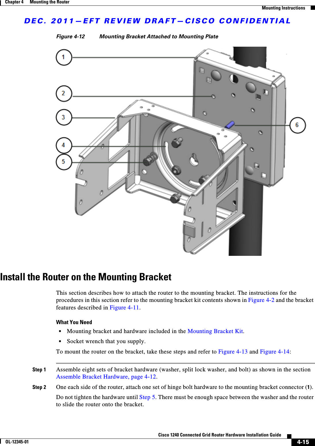
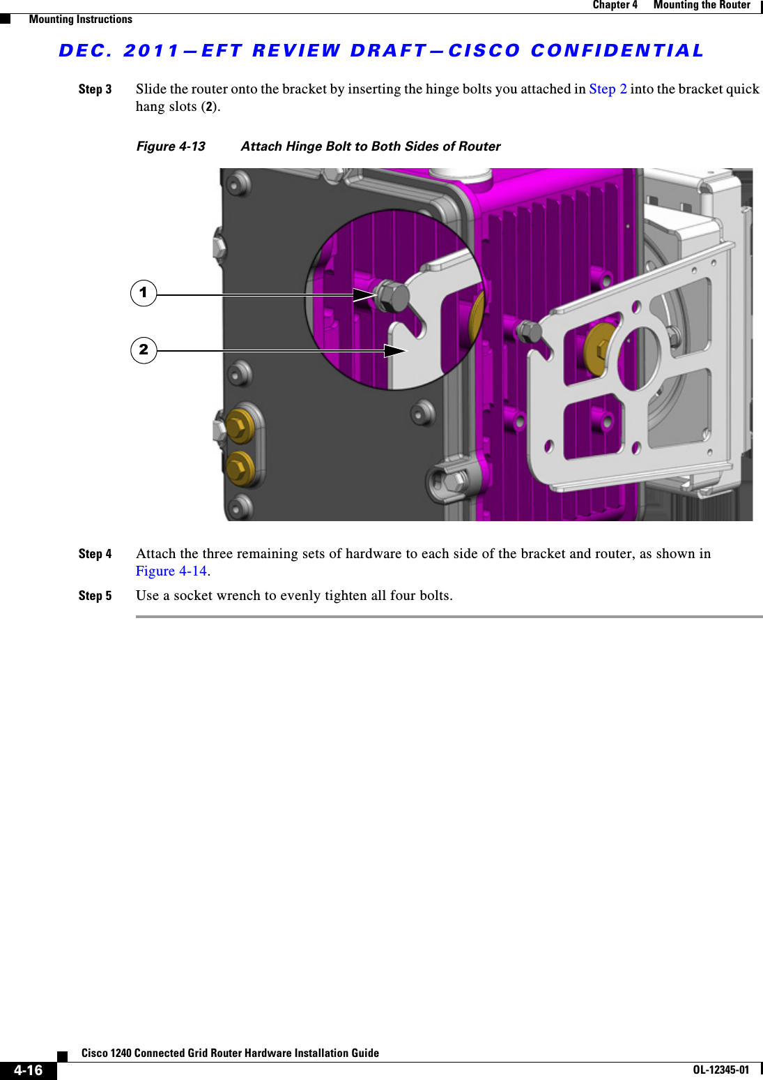
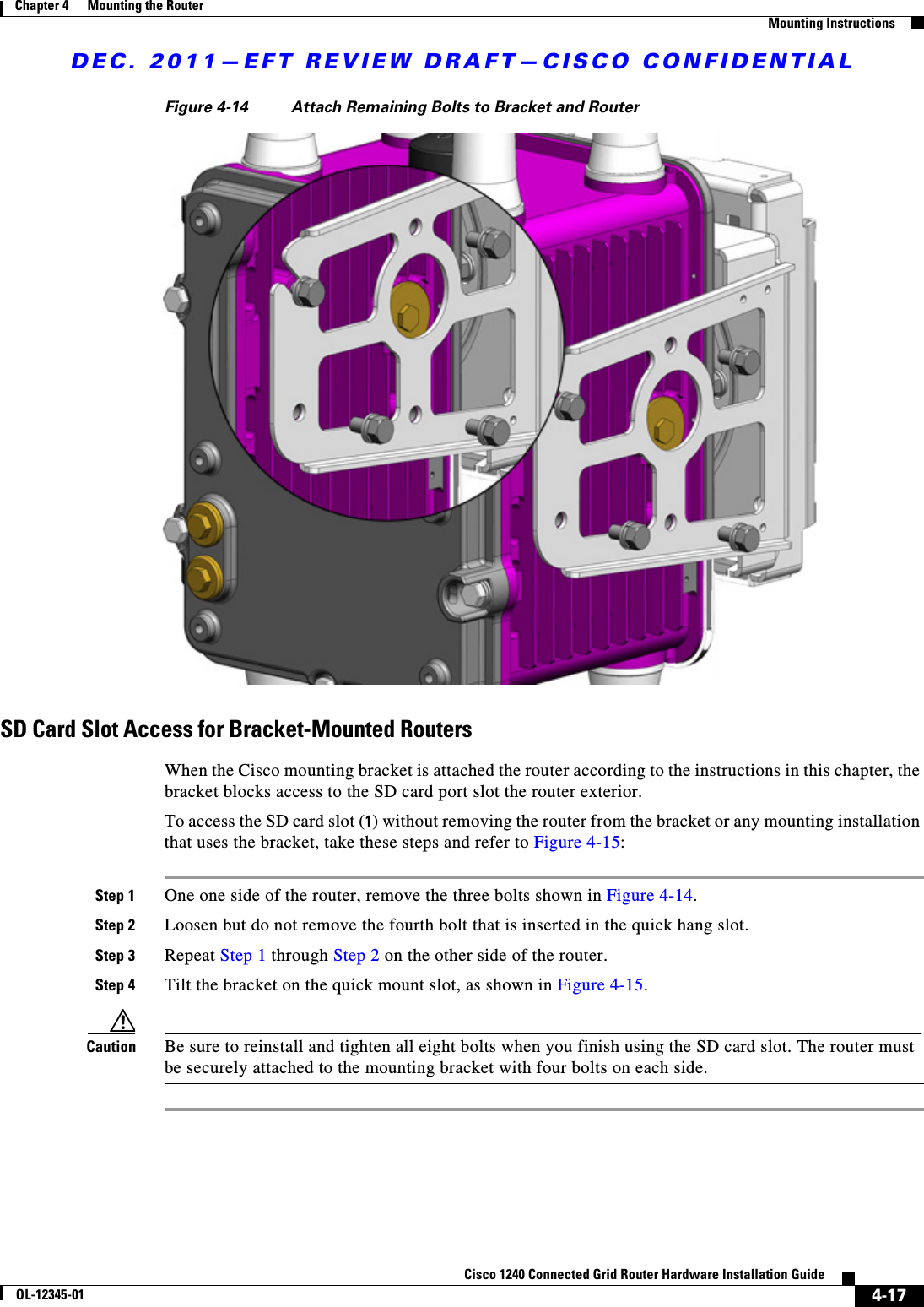
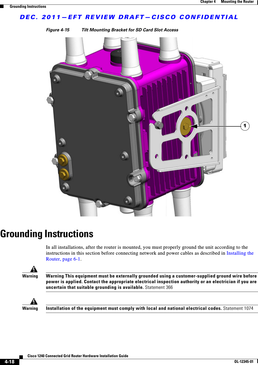
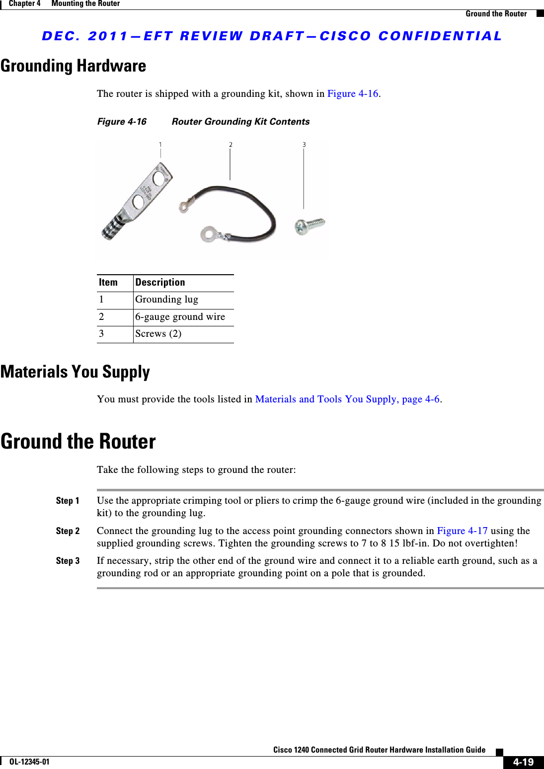
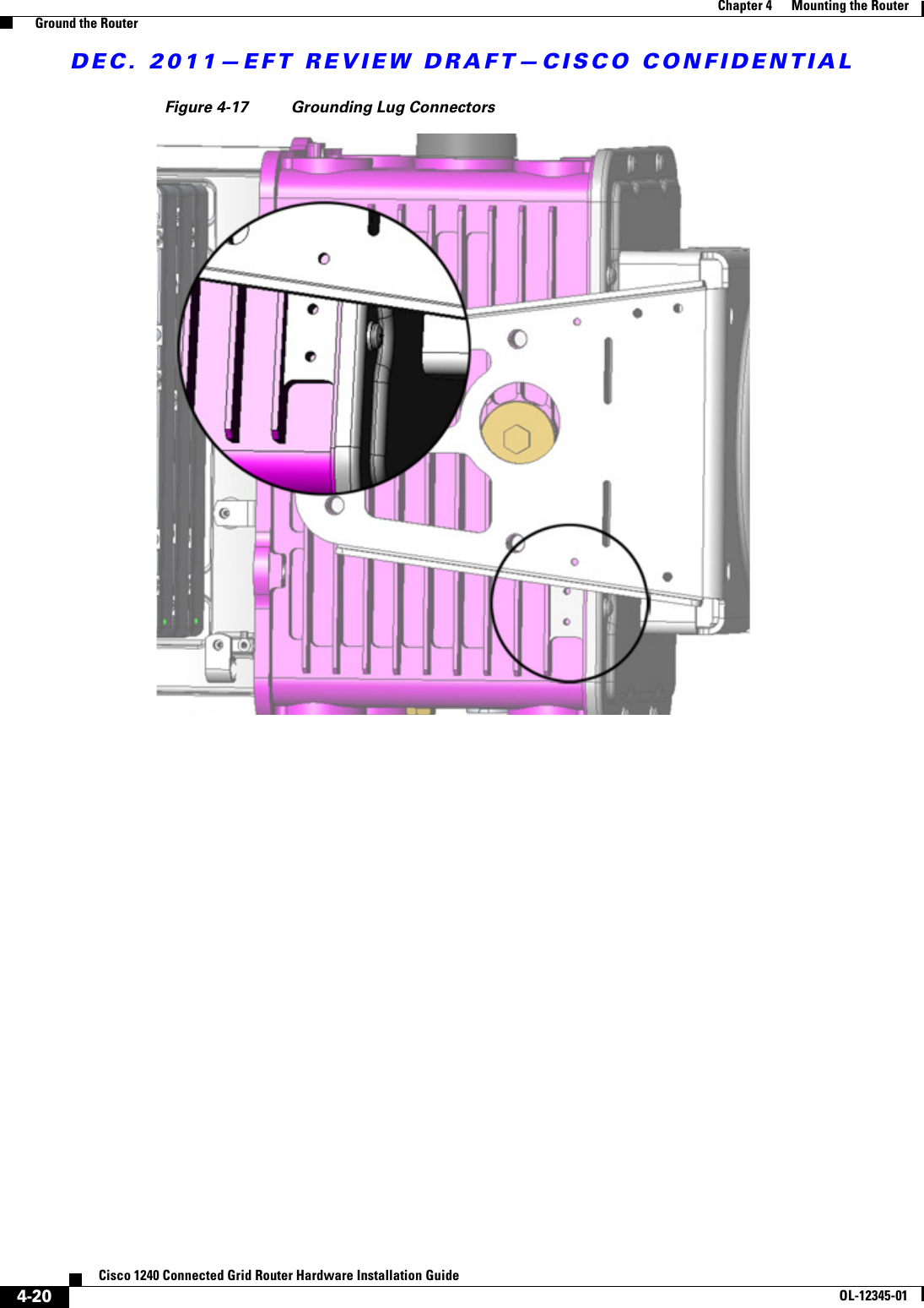
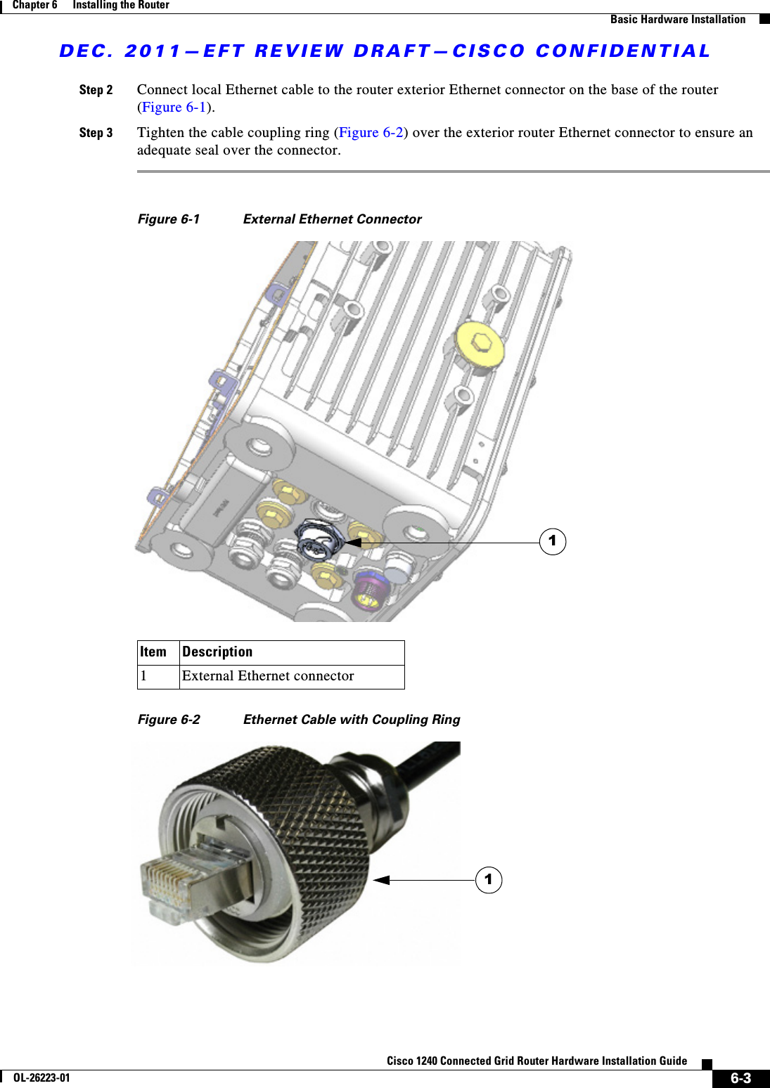
user manual pt 1