Cisco Systems ALTMT0556 Utility Meter Monitoring System User Manual cgr1240hig
Cisco Systems Inc Utility Meter Monitoring System cgr1240hig
Contents
- 1. user manual pt 1
- 2. 3G module manual
- 3. 900 MHz module manual
- 4. user manual pt 2
user manual pt 1

DEC. 2011—EFT REVIEW DRAFT—CISCO CONFIDENTIAL
THE SPECIFICATIONS AND INFORMATION REGARDING THE PRODUCTS IN THIS MANUAL ARE SUBJECT TO CHANGE WITHOUT NOTICE. ALL
STATEMENTS, INFORMATION, AND RECOMMENDATIONS IN THIS MANUAL ARE BELIEVED TO BE ACCURATE BUT ARE PRESENTED WITHOUT
WARRANTY OF ANY KIND, EXPRESS OR IMPLIED. USERS MUST TAKE FULL RESPONSIBILITY FOR THEIR APPLICATION OF ANY PRODUCTS.
THE SOFTWARE LICENSE AND LIMITED WARRANTY FOR THE ACCOMPANYING PRODUCT ARE SET FORTH IN THE INFORMATION PACKET THAT
SHIPPED WITH THE PRODUCT AND ARE INCORPORATED HEREIN BY THIS REFERENCE. IF YOU ARE UNABLE TO LOCATE THE SOFTWARE LICENSE
OR LIMITED WARRANTY, CONTACT YOUR CISCO REPRESENTATIVE FOR A COPY.
The following information is for FCC compliance of Class A devices: This equipment has been tested and found to comply with the limits for a Class A digital device, pursuant
to part 15 of the FCC rules. These limits are designed to provide reasonable protection against harmful interference when the equipment is operated in a commercial
environment. This equipment generates, uses, and can radiate radio-frequency energy and, if not installed and used in accordance with the instruction manual, may cause
harmful interference to radio communications. Operation of this equipment in a residential area is likely to cause harmful interference, in which case users will be required
to correct the interference at their own expense.
The following information is for FCC compliance of Class B devices: This equipment has been tested and found to comply with the limits for a Class B digital device, pursuant
to part 15 of the FCC rules. These limits are designed to provide reasonable protection against harmful interference in a residential installation. This equipment generates,
uses and can radiate radio frequency energy and, if not installed and used in accordance with the instructions, may cause harmful interference to radio communications.
However, there is no guarantee that interference will not occur in a particular installation. If the equipment causes interference to radio or television reception, which can be
determined by turning the equipment off and on, users are encouraged to try to correct the interference by using one or more of the following measures:
• Reorient or relocate the receiving antenna.
• Increase the separation between the equipment and receiver.
• Connect the equipment into an outlet on a circuit different from that to which the receiver is connected.
• Consult the dealer or an experienced radio/TV technician for help.
Modifications to this product not authorized by Cisco could void the FCC approval and negate your authority to operate the product.
The Cisco implementation of TCP header compression is an adaptation of a program developed by the University of California, Berkeley (UCB) as part of UCB’s public
domain version of the UNIX operating system. All rights reserved. Copyright © 1981, Regents of the University of California.
NOTWITHSTANDING ANY OTHER WARRANTY HEREIN, ALL DOCUMENT FILES AND SOFTWARE OF THESE SUPPLIERS ARE PROVIDED “AS IS” WITH
ALL FAULTS. CISCO AND THE ABOVE-NAMED SUPPLIERS DISCLAIM ALL WARRANTIES, EXPRESSED OR IMPLIED, INCLUDING, WITHOUT
LIMITATION, THOSE OF MERCHANTABILITY, FITNESS FOR A PARTICULAR PURPOSE AND NONINFRINGEMENT OR ARISING FROM A COURSE OF
DEALING, USAGE, OR TRADE PRACTICE.
IN NO EVENT SHALL CISCO OR ITS SUPPLIERS BE LIABLE FOR ANY INDIRECT, SPECIAL, CONSEQUENTIAL, OR INCIDENTAL DAMAGES, INCLUDING,
WITHOUT LIMITATION, LOST PROFITS OR LOSS OR DAMAGE TO DATA ARISING OUT OF THE USE OR INABILITY TO USE THIS MANUAL, EVEN IF CISCO
OR ITS SUPPLIERS HAVE BEEN ADVISED OF THE POSSIBILITY OF SUCH DAMAGES.
CCDE, CCENT, Cisco Eos, Cisco HealthPresence, the Cisco logo, Cisco Lumin, Cisco Nexus, Cisco StadiumVision, Cisco TelePresence, Cisco WebEx, DCE, and Welcome
to the Human Network are trademarks; Changing the Way We Work, Live, Play, and Learn and Cisco Store are service marks; and Access Registrar, Aironet, AsyncOS,
Bringing the Meeting To You, Catalyst, CCDA, CCDP, CCIE, CCIP, CCNA, CCNP, CCSP, CCVP, Cisco, the Cisco Certified Internetwork Expert logo, Cisco IOS,
Cisco Press, Cisco Systems, Cisco Systems Capital, the Cisco Systems logo, Cisco Unity, Collaboration Without Limitation, EtherFast, EtherSwitch, Event Center, Fast Step,
Follow Me Browsing, FormShare, GigaDrive, HomeLink, Internet Quotient, IOS, iPhone, iQuick Study, IronPort, the IronPort logo, LightStream, Linksys, MediaTone,
MeetingPlace, MeetingPlace Chime Sound, MGX, Networkers, Networking Academy, Network Registrar, PCNow, PIX, PowerPanels, ProConnect, ScriptShare, SenderBase,
SMARTnet, Spectrum Expert, StackWise, The Fastest Way to Increase Your Internet Quotient, TransPath, WebEx, and the WebEx logo are registered trademarks of
Cisco Systems, Inc. and/or its affiliates in the United States and certain other countries.
All other trademarks mentioned in this document or website are the property of their respective owners. The use of the word partner does not imply a partnership relationship
between Cisco and any other company. (0812R)
No combinations are authorized or intended under this document.
Any Internet Protocol (IP) addresses and phone numbers used in this document are not intended to be actual addresses and phone numbers. Any examples, command display
output, network topology diagrams, and other figures included in the document are shown for illustrative purposes only. Any use of actual IP addresses or phone numbers in
illustrative content is unintentional and coincidental.
© 2012 Cisco Systems, Inc. All rights reserved.

DEC. 2011—EFT REVIEW DRAFT—CISCO CONFIDENTIAL
Contents
iii
Cisco 1240 Connected Grid Router Hardware Installation Guide
OL-26223-01
CONTENTS
CHAPTER
1Unpacking the Router 1-1
Unpacking the Router 1-1
Router Package Contents 1-2
CHAPTER
2Router Hardware Description 2-1
Router Overview 2-1
Router Applications Overview 2-1
Router Hardware Overview 2-2
Compliance 2-2
Exterior Hardware Features 2-4
Interior Hardware Features 2-11
Hardware Feature Descriptions 2-12
Router Exterior Features 2-12
Chassis Enclosure 2-13
Chassis Cable Ports 2-13
Console Port 2-15
SD Flash Memory Module 2-16
100BASE-T Fast Ethernet Connector 2-17
Protective Vent 2-17
AC Power Supply 2-17
Router Interior Features 2-18
Alarm Port 2-18
Connected Grid Module Slots 2-19
Reset Buttons 2-21
Ethernet Ports 2-21
Serial Ports 2-23
Small Form-Factor Pluggable (SFP) Ports 2-24
Combo Ports 2-26
IRIG-B Timing Port 2-26
USB Ports 2-27
Memory 2-29
DC Power for External Devices 2-29
GPS Module 2-29
Short-Range Access Point 2-32
Real-Time Clock (RTC) 2-32
Temperature Sensor 2-33

DEC. 2011—EFT REVIEW DRAFT—CISCO CONFIDENTIAL
Contents
iv
Cisco 1240 Connected Grid Router Hardware Installation Guide
OL-26223-01
CHAPTER
3Installation Safety and Site Preparation 3-1
Safety Recommendations 3-1
Safety with Electricity 3-1
Preventing Electrostatic Discharge Damage 3-2
Safety Warnings 3-2
Site Requirements 3-3
Poletop Installation Requirements 3-4
Environmental Requirements 3-4
FCC Safety Compliance Statement 3-4
Power Guidelines and Requirements 3-4
Preparing for Network Connections 3-5
Ethernet Connections 3-5
Serial Connections 3-5
Exterior 100BASE-T Fast Ethernet Port 3-6
Required Tools and Equipment for Installation and Maintenance 3-7
CHAPTER
4Opening the Router Chassis 4-1
Opening the Router Door 4-1
Preparing to Open the Door 4-1
Tools You Supply 4-1
Safety Information 4-2
Captive Screws 4-2
Order of Loosening and Tightening Door Screws 4-2
Opening the Door 4-3
Closing the Door 4-4
Door Features 4-5
Door Sensor 4-5
Support for Exterior Door Lock 4-6
CHAPTER
5Mounting the Router 5-1
Overview of the Pole Mount Kits 5-1
General Safety Information for Mounting 5-2
Contents of the Mounting Kits 5-2
Pole Mount Kit 5-2
Mounting Bracket Kit 5-3
Band Strap Kit 5-4
Strap Tool Kit 5-5
Materials and Tools You Supply 5-6

DEC. 2011—EFT REVIEW DRAFT—CISCO CONFIDENTIAL
Contents
v
Cisco 1240 Connected Grid Router Hardware Installation Guide
OL-26223-01
Mounting Instructions 5-6
Router Orientation 5-6
Install the Mounting Plate on a Pole 5-6
Install the Mounting Plate—Poles Up to 5 Inches in Diameter 5-7
Install the Mounting Plate—Poles Larger than 5 Inches in Diameter 5-9
Install the Mounting Plate—Through-Pole Mounting (Optional) 5-11
Attach the Mounting Bracket 5-12
Assemble Bracket Hardware 5-12
Install the Router on the Mounting Bracket 5-15
SD Card Slot Access for Bracket-Mounted Routers 5-17
Grounding Instructions 5-18
Grounding Hardware 5-19
Materials You Supply 5-19
Ground the Router 5-19
CHAPTER
6Installing the Router 6-1
Before Installing 6-1
Prepare the Installation Site 6-1
Read the Safety Information 6-1
Preventing Electrostatic Discharge Damage 6-1
Cabling Guidelines 6-2
Related Information 6-2
Basic Hardware Installation 6-2
Connect to the Ethernet Backhaul Network 6-3
Connecting to AC Power 6-4
AC Power Cable 6-5
Connect to AC Power 6-5
Power and Reset Buttons 6-7
Accessing the Buttons 6-7
Related Information 6-7
Verify the Router Basic Installation 6-8
Check the System (SYS) LED 6-8
Use the show interface Command 6-9
Additional Router Connections 6-10
External Connections and Chassis Cable Ports 6-10
Using Cable Glands 6-11
Ordering Cisco Cable Glands 6-11
Tools You Supply 6-12
Cable Glands Description 6-12

DEC. 2011—EFT REVIEW DRAFT—CISCO CONFIDENTIAL
Contents
vi
Cisco 1240 Connected Grid Router Hardware Installation Guide
OL-26223-01
Cable Requirements 6-13
Cable Glands Installation Steps 6-13
Connecting the Console Port 6-15
About 6-15
Connecting 6-15
Related Information 6-16
Connecting the Serial Port 6-16
About 6-16
Connecting 6-17
Related Information 6-17
Connecting the USB Ports 6-17
About 6-17
Connecting 6-17
Related Information 6-18
Connecting the SFP Ports 6-18
About 6-18
Materials and Tools You Supply 6-19
Connecting 6-19
Related Information 6-20
Connecting the Ethernet Ports 6-20
About 6-20
Connecting 6-20
Related Information 6-21
Connecting the Alarm Port 6-22
About 6-22
Connecting 6-22
Related Information 6-22
Connecting the IRIG-B Port 6-23
About 6-23
Connecting 6-23
Related Information 6-23
Installing Modules and Antennas 6-24
CHAPTER
7About Router Connected Grid Modules 7-1
Module Installation and Configuration Information 7-1
CHAPTER
8About Router Antennas 8-1
Installing or Replacing Antennas 8-1
Lightning Arrestor 8-1

DEC. 2011—EFT REVIEW DRAFT—CISCO CONFIDENTIAL
Contents
vii
Cisco 1240 Connected Grid Router Hardware Installation Guide
OL-26223-01
Cisco Connected Grid Modules 8-2
Antennas Overview 8-2
GPS Antenna 8-2
WiFi Antenna 8-3
Connected Grid Module Antennas 8-4
Antenna Ports 8-5
Unused Antenna Ports 8-5
Antenna Port Numbering 8-5
Antenna Installation Location 8-6
Safety Information 8-7
Antenna Technical Specifications 8-7
GPS Antenna Specifications 8-8
WiFi Antenna Specifications 8-9
CHAPTER
9Using the SD Flash Memory Module 9-1
SD Card Overview 9-1
Supported SD Cards 9-2
Accessing the SD Card 9-2
Inserting the SD Card 9-3
Online Insertion and Removal (OIR) 9-3
Safety Warnings 9-4
Preventing Electrostatic Discharge Damage 9-4
Tools You Supply 9-4
Removing and Inserting the SD Card 9-4
SD Card Status 9-6
SD Card LED 9-6
Related Commands 9-7
CHAPTER
10 Installing Battery Backup Units 10-1
Battery Backup Unit (BBU) Description 10-1
Enabling the BBU 10-2
Battery Backup Mode 10-3
Charging the BBU 10-3
BBU Capacity 10-4
Preparing to Install the BBU 10-4
Tools You Supply 10-4
Safety Information for Installation 10-4
Safety Warnings 10-4

DEC. 2011—EFT REVIEW DRAFT—CISCO CONFIDENTIAL
Contents
viii
Cisco 1240 Connected Grid Router Hardware Installation Guide
OL-26223-01
Preventing Electrostatic Discharge Damage 10-4
BBU Components 10-5
Battery-to-Battery Connectors 10-5
Captive Screws 10-5
Battery-to-Router Connector 10-8
Locating Pin and Notch 10-9
Router Door BBU Connectors 10-10
BBU Cable Harness 10-10
Installing a BBU in the Router 10-11
Battery Backup Unit LED 10-15
Related Commands 10-16
backup-battery reset 10-16
backup-battery inhibit discharge 10-16
poweroff module number backup-battery 10-17
BBU Technical Specifications 10-17
Router Power Path Selection 10-17
Discharge Conditions 10-18
Charge Conditions 10-19
Operating and Storage Temperatures 10-19
Battery Life 10-19
Battery Standards 10-20
CHAPTER
11 Installing Non-Cisco Modules 11-1
Non-Cisco Module Support 11-1
Non-Cisco Module Requirements 11-1
Online Installation and Removal 11-2
Certification 11-2
Power 11-2
Before Installing 11-2
Prepare the Installation Site 11-2
Read the Safety Information 11-2
Preventing Electrostatic Discharge Damage 11-2
Cabling Guidelines 11-3
Install a Non-Cisco Module 11-3
Tools and Materials You Supply 11-3
Open and Close the Router Door 11-3
Connect the Module to the Chassis 11-4
Installation Options 11-4
Cabling Instructions 11-6

DEC. 2011—EFT REVIEW DRAFT—CISCO CONFIDENTIAL
Contents
ix
Cisco 1240 Connected Grid Router Hardware Installation Guide
OL-26223-01
External Cabling 11-7
Internal Cabling 11-7
Connect to the Network 11-8
Connect to Power 11-9
Related Information 11-9
CHAPTER
12 Router LED Locations and States 12-1
LED Locations and State Descriptions 12-2
System Status (SYS) LED 12-2
Alarm and Network Connection LEDs 12-3
ALARM LEDs 12-3
Fast Ethernet LEDs 12-4
Combo Port LEDs 12-4
System LEDs 12-5
WiFi and GPS LEDs 12-5
Battery Backup Unit LED 12-6
SD Card (SD0) LED 12-7
Related Commands 12-8
show led 12-8
show interface 12-8
APPENDIX
AConnector and Cable Specifications A-1
Connector Specifications A-1
GPS Serial Port A-1
Alarm Ports A-2
Console Port A-2
Copper Interface—Combination Port (SFP and GE Ethernet) A-2
SFP Interface—Combination Port (SFP and GE Ethernet) A-3
Serial Port A-4
AC Power Supply Connector A-4
AC Power Supply Output Connector A-5
Battery Backup Unit Cable Connector A-5
Non-Cisco Module Power Connector A-6
Connected Grid Module Slots A-6
Cable and Adapter Specifications A-8
SFP Cable A-8
APPENDIX
BStarting a Router Terminal Session B-1
Before You Begin B-1

DEC. 2011—EFT REVIEW DRAFT—CISCO CONFIDENTIAL
Contents
x
Cisco 1240 Connected Grid Router Hardware Installation Guide
OL-26223-01
About the Console Port B-1
Console Port Settings B-1
Using the Ctrl-C Command B-2
Connecting to the Console Port with Microsoft Windows B-2
Connecting to the Console Port with Mac OS X B-2
Connecting to the Console Port with Linux B-3
I
NDEX

CHAPTER
DEC. 2011—EFT REVIEW DRAFT—CISCO CONFIDENTIAL
1-1
Cisco 1240 Connected Grid Router Hardware Installation Guide
OL-26223-01
1
Unpacking the Router
This chapter includes instructions about how to unpack the Cisco 1240 Connected Grid Router and
describes the items that ship with the router. This chapter includes the following sections:
• Unpacking the Router, page 1-1
• Router Package Contents, page 1-2
Unpacking the Router
Tip When you unpack the router, do not remove the foam blocks attached to antennas and antenna
connectors. The foam protects the antennas and connectors during installation.
Follow these steps to unpack the router:
Step 1 Open the shipping container and carefully remove the contents.
Step 2 Return all packing material to the shipping container, and save it.
Step 3 Ensure that all items listed in the section Router Package Contents, page 1-2 are included in the
shipment. If any item is damaged or missing, notify your authorized Cisco sales representative.

DEC. 2011—EFT REVIEW DRAFT—CISCO CONFIDENTIAL
1-2
Cisco 1240 Connected Grid Router Hardware Installation Guide
OL-26223-01
Chapter 1 Unpacking the Router
Router Package Contents
Router Package Contents
Your router kit contains the items listed in Table 1-1.
Table 1-1 Router Package Contents
Qty. Item Description
1Cisco Connected Grid 1240 Router Router chassis
1SD Flash memory module 1GB, 2GB, or 3GB
1AC Power Kit Each kit includes:
• AC power supply (integrated in router)
• AC power cord, 15 ft.
1Console cable RJ-45-to-DB-9
1Mounting kit • Pole mount bracket
• Pole mount clamps (2)
• Stainless steel bands (2)
• Electrical join compound
• All required hardware
For details, see the chapter Mounting the Router.
1Grounding kit Grounding lug, screw, 6-gauge wire
1-4 Connected Grid Modules Depends on configuration ordered
1-7 Connected Grid Antennas Depends on configuration ordered
2Battery backup units (BBU) Up to 12 hours, based on configuration order.
For details, see the chapter Installing Battery Backup
Units.

CHAPTER
DEC. 2011—EFT REVIEW DRAFT—CISCO CONFIDENTIAL
2-1
Cisco 1240 Connected Grid Router Hardware Installation Guide
OL-12345-01
2
Router Hardware Description
This chapter describes the major hardware features of the Cisco 1240 Connected Grid Router, including
the chassis and the internal and external connectors and ports. This chapter contains the following
sections:
• Router Overview, page 2-1
–
Exterior Hardware Features, page 2-4
–
Interior Hardware Features, page 2-11
• Hardware Features Detailed Description, page 2-12
Note This chapter is intended to provided information about the router connector and ports. For instruction on
installing the router, including connecting all network and other ports, see the chapter Installing the
Router.
Router Overview
Router Applications Overview
The Cisco 1240 Connected Grid Router is designed for use in Field Area Networks (FANs) in North
American power distribution grids, and in regions with similar distribution grid architectures. A FAN
can also be referred to as a Neighborhood Area Network (NAN). The Smart Grid FAN is a distribution
system in which power generation and transmission are linked to the power consumers.
The router provides an end-to-end communication network that enables increased power grid efficiency
and reliability, reduced energy consumption, and reduced greenhouse gas emissions. The router also
enables distributed intelligence for converged smart grid applications, including:
• Advanced Metering Infrastructure (AMI)
• Demand Response (DR)
• Distribution Automation (DA)
• Integration of Distributed Energy Resources (DER), also known as Renewable Energy Sources
(RES) and Distributed Generation (DG)
• Power asset management
• Workforce automation

DEC. 2011—EFT REVIEW DRAFT—CISCO CONFIDENTIAL
2-2
Cisco 1240 Connected Grid Router Hardware Installation Guide
OL-12345-01
Chapter 2 Router Hardware Description
Router Overview
The router provides reliable and secure real-time communication between the FAN network systems and
the millions of devices that exist on the FAN, including as meters, sensors, protection relays, Intelligent
Electronic Devices (IEDs), plug-in electric vehicle (PEV) charging stations, and distributed solar farms.
Network data is forwarded and processed over secure communication links between devices within the
distribution grid for local decision processing. Additionally, this data is sent to Supervisory Control and
Data Acquisition (SCADA) and other management systems.
Hardware Compliance
For a complete list of regulatory and compliance standards supported by the Cisco CGR 1240 Router,
see the Regulatory Compliance and Safety Information for the Cisco 1000 Series Routers document on
Cisco.com.
Router Hardware Overview
The Cisco 1240 Connected Grid Router is a modular, ruggedized router that features:
• Four module slots that support ruggedized Connected Grid wireless modules
• Support for fiber Gigabit Ethernet and copper Fast Ethernet connections
• Integrated serial ports
• Automated battery backup power
DEC. 2011—EFT REVIEW DRAFT—CISCO CONFIDENTIAL
2-3
Cisco 1240 Connected Grid Router Hardware Installation Guide
OL-12345-01
Chapter 2 Router Hardware Description
Router Overview
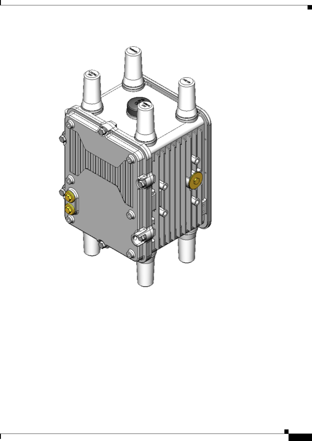
Figure 2-1 Cisco 1240 Connected Grid Router with Integrated Antennas Installed
DEC. 2011—EFT REVIEW DRAFT—CISCO CONFIDENTIAL
2-4
Cisco 1240 Connected Grid Router Hardware Installation Guide
OL-12345-01
Chapter 2 Router Hardware Description
Router Overview
Exterior Hardware Features
This section illustrates the router exterior hardware features and includes a brief description of each
feature. Detailed descriptions of each feature are in the Hardware Features Detailed Description,
page 2-12 section later in this chapter, or in other chapters in this document.
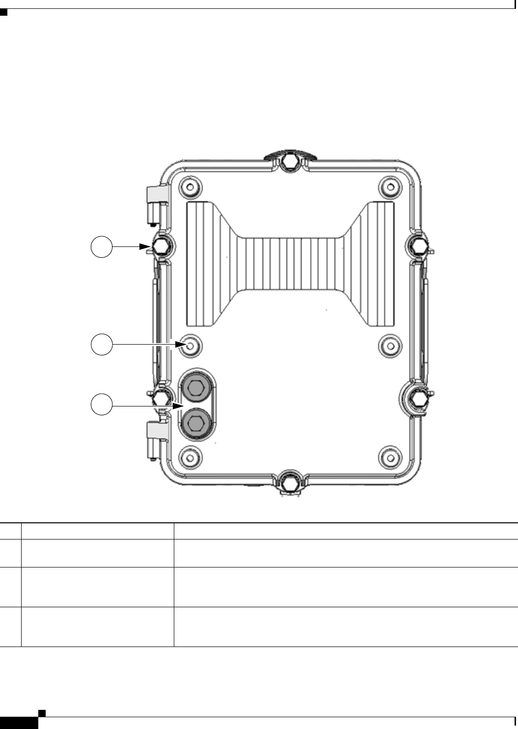
Figure 2-2 Router Front Exterior
Table 2-1 Router Front Exterior Features
Description Detailed Information
1M8 captive screws (8) Loosen these screws to access the router interior. For information about opening
the chassis, see the chapter Opening the Router Chassis.
2Module mounting bosses (6) Mount a supported non-Cisco module (optional) to the front exterior of the router
using these mounting bosses. For more information on connecting a module to the
router exterior, see the chapter Installing Non-Cisco Modules.
3Module cable ports (2) Thread cables through these ports, to ports and connectors inside the router, when
installing a module on the router exterior. For more information on connecting a
module to the router exterior, see the chapter Installing Non-Cisco Modules.
1
2
3
DEC. 2011—EFT REVIEW DRAFT—CISCO CONFIDENTIAL
2-5
Cisco 1240 Connected Grid Router Hardware Installation Guide
OL-12345-01
Chapter 2 Router Hardware Description
Router Overview
Figure 2-3 Router Front with Mounting Bracket and Lock
Table 2-2 Router Bracket and Lock Features
Description Detailed Information
1Mounting bracket Use the mounting bracket with the Cisco pole mount kit to install the router on a pole.
For information about router mounting options and procedures, see the chapter Mounting the
Router.
2Door lock block Use the lock block to install a lock that you supply on the router door, preventing unauthorized
physical access to the router interior.
For information about physical security features for the router chassis, see the chapter Opening
the Router Chassis.
2
1
DEC. 2011—EFT REVIEW DRAFT—CISCO CONFIDENTIAL
2-6
Cisco 1240 Connected Grid Router Hardware Installation Guide
OL-12345-01
Chapter 2 Router Hardware Description
Router Overview
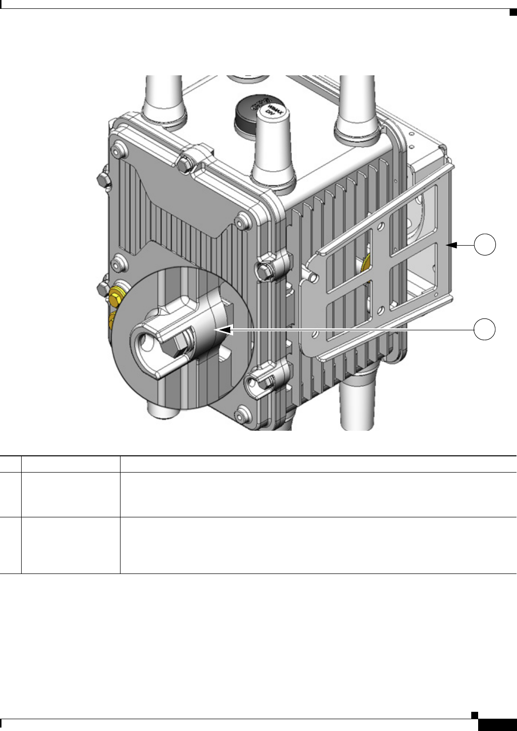
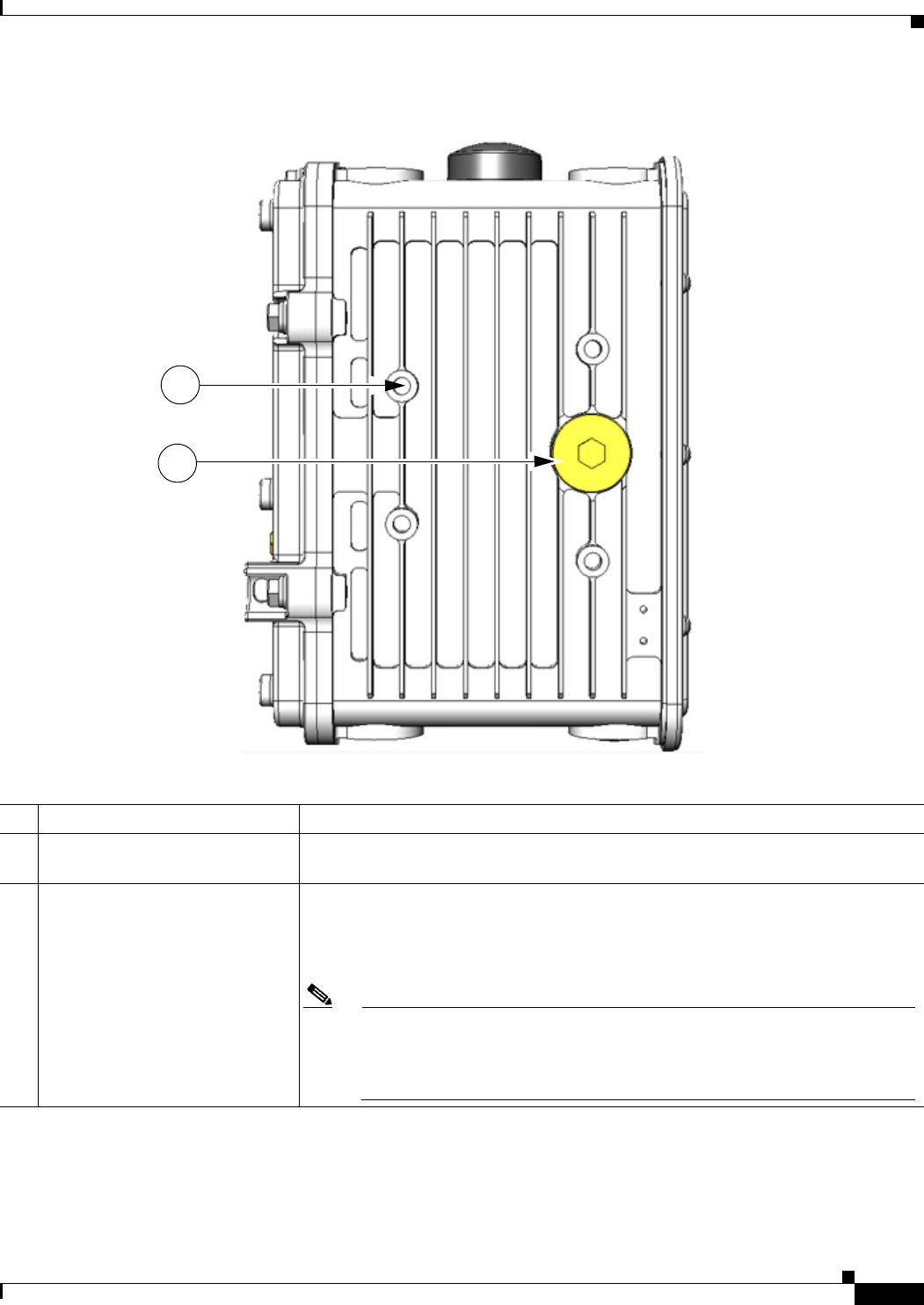
Figure 2-4 Router Right Side Exterior
Table 2-3 Router Right Side Exterior Features
Description Detailed Information
1Console port access Remove the plug shown here to access the console port. This port is described in the
section Console Port, page 2-15, later in this chapter. For detailed information about
connecting to this port, see the chapter chapter Installing the Router.
2Mounting bracket connectors (4) Mount supported brackets to the router using these connectors. For information
about router mounting options and procedures, see the chapter Mounting the Router.
1
2
DEC. 2011—EFT REVIEW DRAFT—CISCO CONFIDENTIAL
2-7
Cisco 1240 Connected Grid Router Hardware Installation Guide
OL-12345-01
Chapter 2 Router Hardware Description
Router Overview
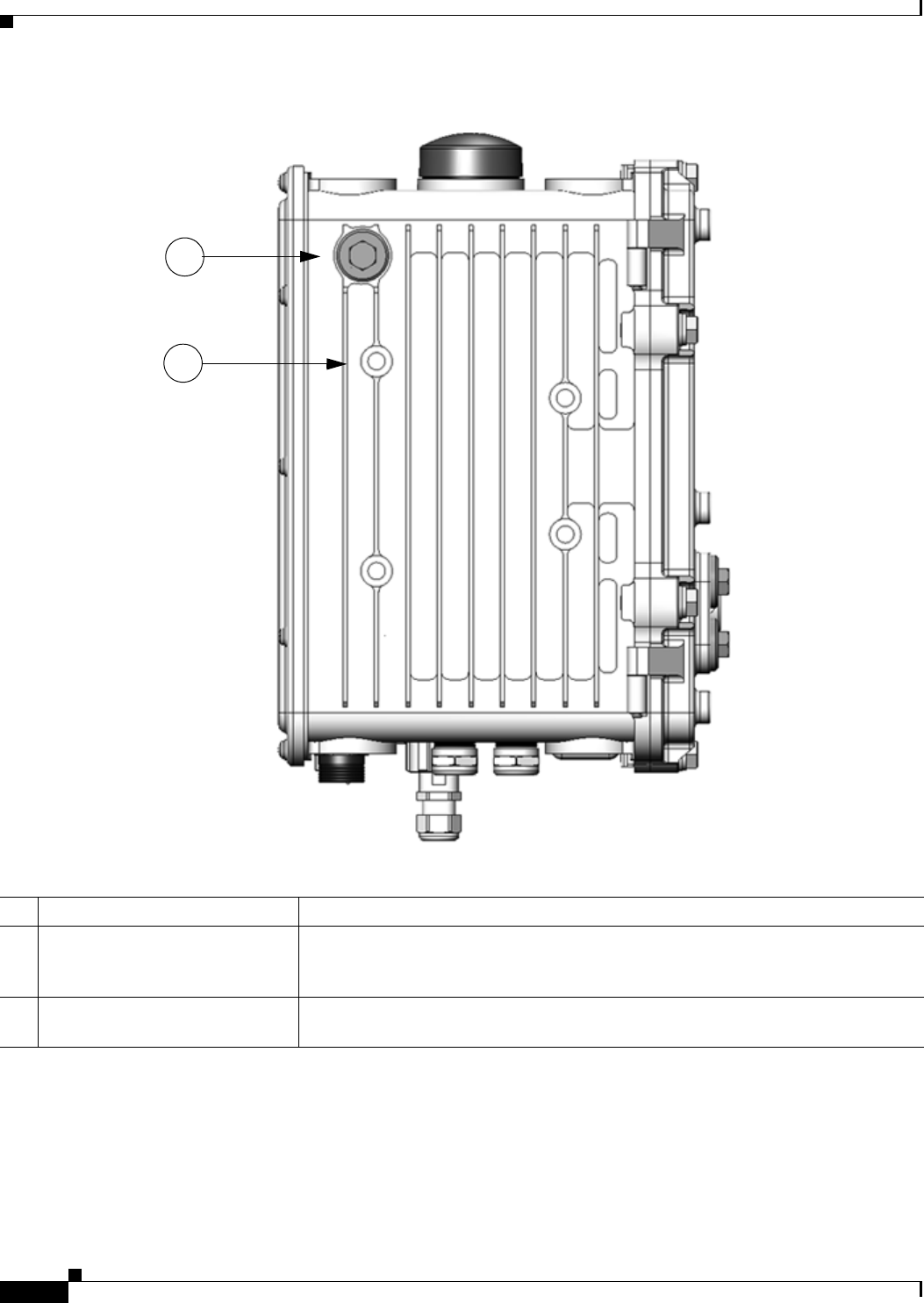
Figure 2-5 Router Left Side Exterior
Table 2-4 Router Left Side Exterior Features
Description Detailed Information
1Mounting bracket connectors (4) Mount supported brackets to the router using these connectors. For information
about router mounting options and procedures, see the chapter Mounting the Router.
2SD flash memory module port Remove the plug shown here for access to the router SD module, which is described
in the SD Flash Memory Module, page 2-16, later in this chapter. For detailed
information about using an SD flash memory module with the router, see the chapter
Using the SD Flash Memory Module.
Note When a mounting bracket is installed on the router, the bracket blocks
access to the SD card port. In order to access the port after the bracket is
installed, you must remove the router from the pole, and rotate the bracket
away from the port. For detailed instructions,
1
2
DEC. 2011—EFT REVIEW DRAFT—CISCO CONFIDENTIAL
2-8
Cisco 1240 Connected Grid Router Hardware Installation Guide
OL-12345-01
Chapter 2 Router Hardware Description
Router Overview
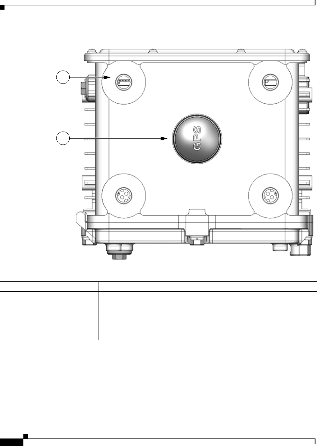
Figure 2-6 Router Top Exterior
Table 2-5 Router Top Exterior Features
Description Detailed Information
1Antenna connectors (4) Install supported integrated or external antennas in these ports. For detailed
information about the router antennas, including how to find installation instructions,
see the chapter About Router Antennas.
2GPS antenna The GPS antenna connects the router GPS, which is described in GPS Module,
page 2-29, to the GPS source. For more information about GPS antenna, including
specifications and frequencies supported, see the chapter About Router Antennas.
1
2
DEC. 2011—EFT REVIEW DRAFT—CISCO CONFIDENTIAL
2-9
Cisco 1240 Connected Grid Router Hardware Installation Guide
OL-12345-01
Chapter 2 Router Hardware Description
Router Overview
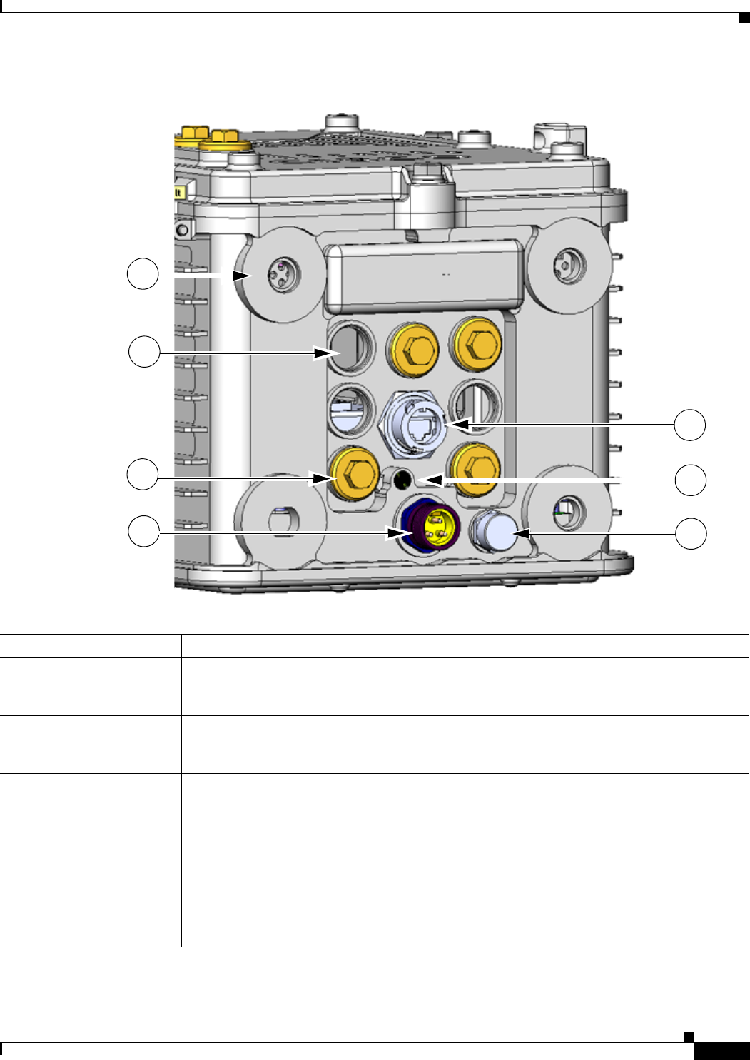
Figure 2-7 Router Base Exterior
Table 2-6 Router Base Exterior Features
Description Detailed Information
1Antenna connectors (4) Install supported integrated or external antennas in these ports. For detailed information about
the router antennas and information about installation instructions, see the chapter About
Router Antennas.
2Cable ports (7) Use a cable glands to thread network cables through these ports when installing the router.
Unused ports are sealed with standard, environmental-proof plugs. For detailed descriptions
of supported cable glands and plugs, see Chassis Cable Ports, page 2-13.
3Port plugs (up to 7) Use port plugs to seal unused cable ports and protect the router interior from environmental
elements. For a detailed description of supported plugs, see Chassis Cable Ports, page 2-13.
4AC power connector Connect the router AC power connector to a power source to power on the router. For detailed
information about the connecting the router to the AC power supply, see AC Power Supply,
page 2-17.
5100BASE-T Fast
Ethernet (FE) port
Use this connector to connect the router to a 100BASE-T Ethernet network without requiring
access to the router interior. This port is connected to one of the router internal FE ports. For
detailed information on connecting the router to an Ethernet network, see to Installing the
Router.
4
6
5
7
3
2
1

DEC. 2011—EFT REVIEW DRAFT—CISCO CONFIDENTIAL
2-10
Cisco 1240 Connected Grid Router Hardware Installation Guide
OL-12345-01
Chapter 2 Router Hardware Description
Router Overview
6System (SYS) LED View the System LED to determine the overall operating and power status of the router. For
detailed information about all the route LEDs, see the chapter Router LED Locations and
States.
7Protective vent The chassis vent relieves pressure buildup inside the router chassis. For a description of the
vent, see Protective Vent, page 2-17.
Table 2-6 Router Base Exterior Features
DEC. 2011—EFT REVIEW DRAFT—CISCO CONFIDENTIAL
2-11
Cisco 1240 Connected Grid Router Hardware Installation Guide
OL-12345-01
Chapter 2 Router Hardware Description
Router Overview
Interior Hardware Features
This section illustrates the router front panel hardware features and includes a brief description of each
feature. Detailed descriptions of each feature are in Hardware Features Detailed Description, page 2-12,
later in this chapter, or in other chapters in this document.
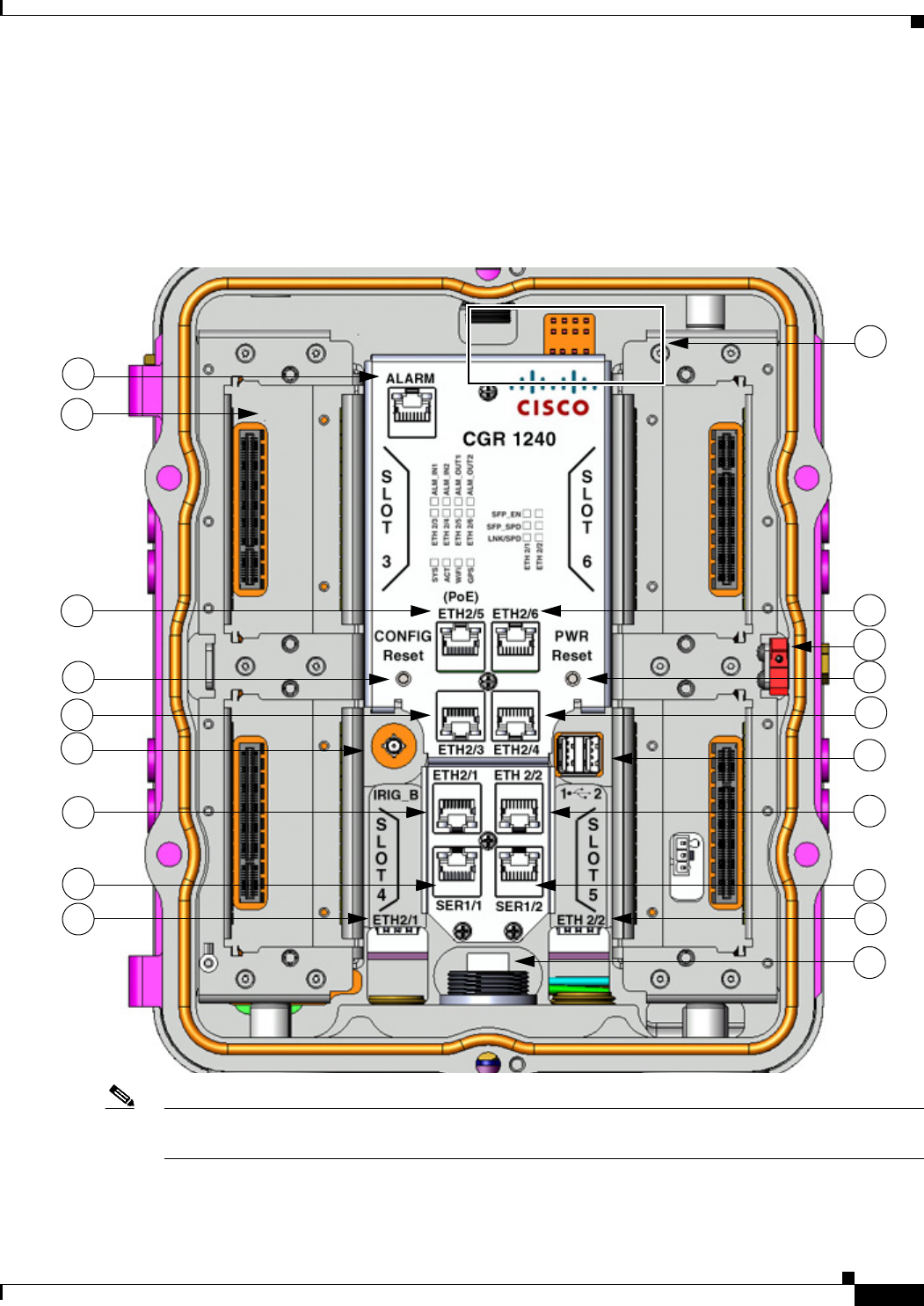
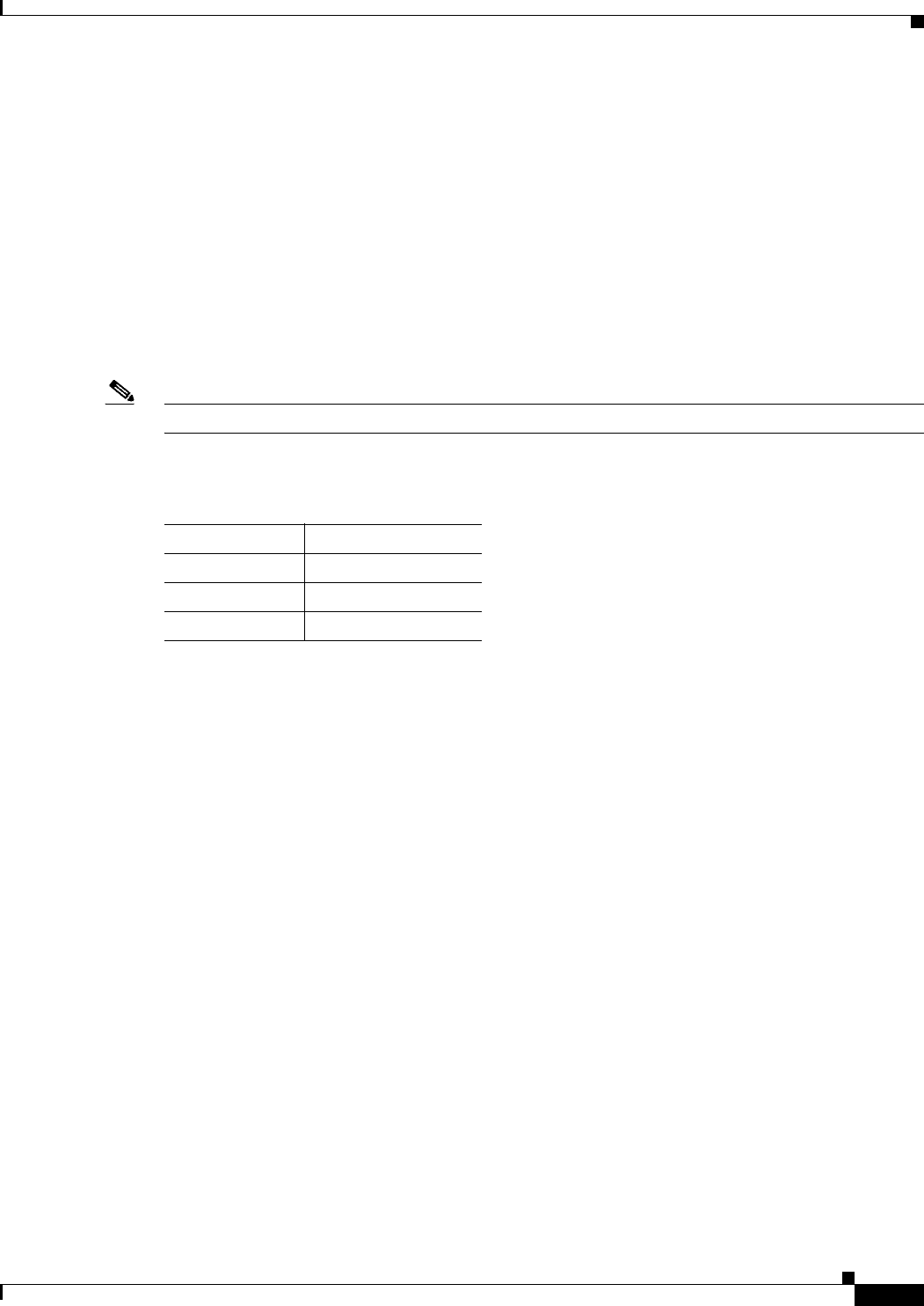
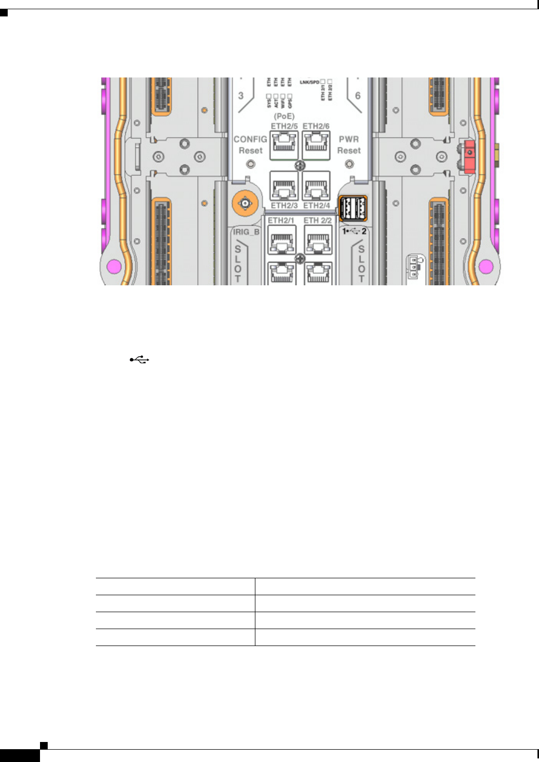
Figure 2-8 Interior Front Panel Hardware Features
Note In Table 2-7, items indicated with a footnote 1 are currently not supported, and will be supported in a
future software release.
1
2
3
4
5
3
3
11
3
12
6
77
88
13
6
9
10

DEC. 2011—EFT REVIEW DRAFT—CISCO CONFIDENTIAL
2-12
Cisco 1240 Connected Grid Router Hardware Installation Guide
OL-12345-01
Chapter 2 Router Hardware Description
Hardware Features Detailed Description
Hardware Features Detailed Description
This section provides detailed information about all of the router hardware features, including
descriptions, illustrations, specifications, and links to related information. This section is divided into
two topics:
• Router Exterior Hardware Features, page 2-13
• Router Hardware Interior Features, page 2-18
Table 2-7 Interior (Front Panel) Features
Label Description
1ALARM1
1. Currently not supported. This hardware feature will be supported in a future software release.
Connect this alarm port to an alarm system to monitor system errors and events. For
more information, see Alarm Port, page 2-18.
2SLOT 3, SLOT4,
SLOT 5, SLOT 6
Install Cisco Connected Grid modules in these four Connected Grid module slots. For
more information, see Connected Grid Module Slots, page 2-19.
3ETH 2/3, ETH 2/4,
ETH 2/5, ETH 2/6
Make 10/100 Mbps Ethernet network connections using these four Fast Ethernet
ports. For more information, see Fast Ethernet Ports, page 2-22.
4CONFIG Reset Press the CONFIG reset button to reset the router to the default software
configuration. For more information, see Reset Buttons, page 2-21.
5IRIG_B1Connect the IRIG-B timing port (time source: router GPS Module) to any device that
requires precise time. For more information, see IRIG-B Timing Port, page 2-26.
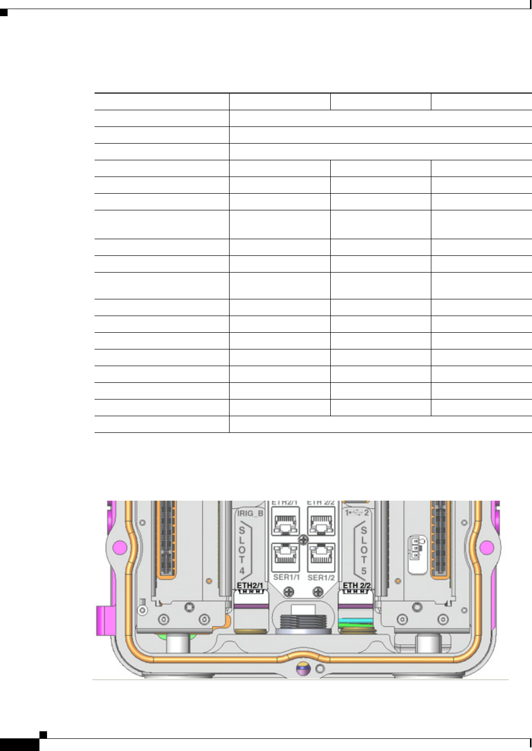
6ETH 2/1, ETH 2/2 Make 100/1000 Mbps Ethernet network connections using these two Gigabit Ethernet
ports. For more information, see Gigabit Ethernet Ports, page 2-22.
7SER 1/1, SER 1/21Connect the router to DTE or DCE devices using these two serial ports. For more
information on these ports and supported devices, see Serial Ports, page 2-23.
8ETH 2/1, ETH 2/2 Install supported small-form-factor pluggable (SFP) modules in these two SFP ports.
For more information and supported SFPs, see Small Form-Factor Pluggable (SFP)
Ports, page 2-24.
9–The LEDs indicate alarm port status and connection status for Ethernet, WiFi, and
GPS connections. The LED label is located in the center of the chassis (see
Figure 2-8). For more information, see the chapter Router LED Locations and States.
10 –The door alarm switch triggers the router to generate a syslog event and send an
SNMP alarm when the door is opened. For more information on physical security
features of the router chassis, see the chapter Opening the Router Chassis.
11 PWR Reset Press the PWR Rest button to cycle the router power without powering off the router.
The router cannot be powered off with this button. For more information, see Reset
Buttons, page 2-21.
12
Connect these USB ports to supported, external USB devices. For more information,
see USB Ports, page 2-27.
13 –Use the external Fast Ethernet connector to connect the router to an Ethernet network
without requiring access to the router interior. This port is connected to one of the
router internal FE ports. For more information, see the chapter Installing the Router.
1 2

DEC. 2011—EFT REVIEW DRAFT—CISCO CONFIDENTIAL
2-13
Cisco 1240 Connected Grid Router Hardware Installation Guide
OL-12345-01
Chapter 2 Router Hardware Description
Hardware Features Detailed Description
Router Exterior Hardware Features
This section includes detailed information about the exterior hardware features illustrated in the Exterior
Hardware Features section, and contains the following topics:
• Chassis Enclosure, page 2-13
• Chassis Cable Ports, page 2-13
• Console Port, page 2-15
• SD Flash Memory Module, page 2-16
• 100BASE-T Fast Ethernet Connector, page 2-17
• Protective Vent, page 2-17
• AC Power Supply, page 2-17
Chassis Enclosure
The Cisco CGR 1240 Router industrial enclosure (see Figure 2-1) meets Type 4X and IP67 standards
and is designed for deployment in extreme weather. The enclosure can be painted to comply with
aesthetic requirements.
Specifications
Additional Information
For router regulatory compliance information, see the Regulatory Compliance and Safety Information
for the Cisco 1000 Series Routers on Cisco.com, at: URL-TBD
Chassis Cable Ports
The router chassis has the following cable ports for router network and power cables:
• Door—Two cable ports on the front door, shown in Figure 2-2, provide support for third party radio
cabling. The router supports installation of a compatible radio, as described in Installing Non-Cisco
Modules.
• Base—Seven cable ports on the router base, shown in Figure 2-7, provide support for router
network cabling, as described in Installing the Router.
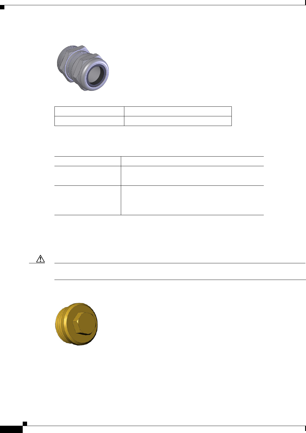
Cable Glands
A cable gland (also known as a cable connector) is required to install cables in the chassis cable ports.
Use a compatible cable gland to attach and secure the end of a cable to the router. The cable gland
provides cable strain relief and seals the cable entry into the router chassis to prevent damage to the
router interior.
Specification Description
Dimensons 12 x 8 x 7.5 inches (30.5 x 20.3 x 19 cm)
Environmental Type 4x compliant
IP67 compliant
DEC. 2011—EFT REVIEW DRAFT—CISCO CONFIDENTIAL
2-14
Cisco 1240 Connected Grid Router Hardware Installation Guide
OL-12345-01
Chapter 2 Router Hardware Description
Hardware Features Detailed Description
Figure 2-9 Cable Gland
Specifications
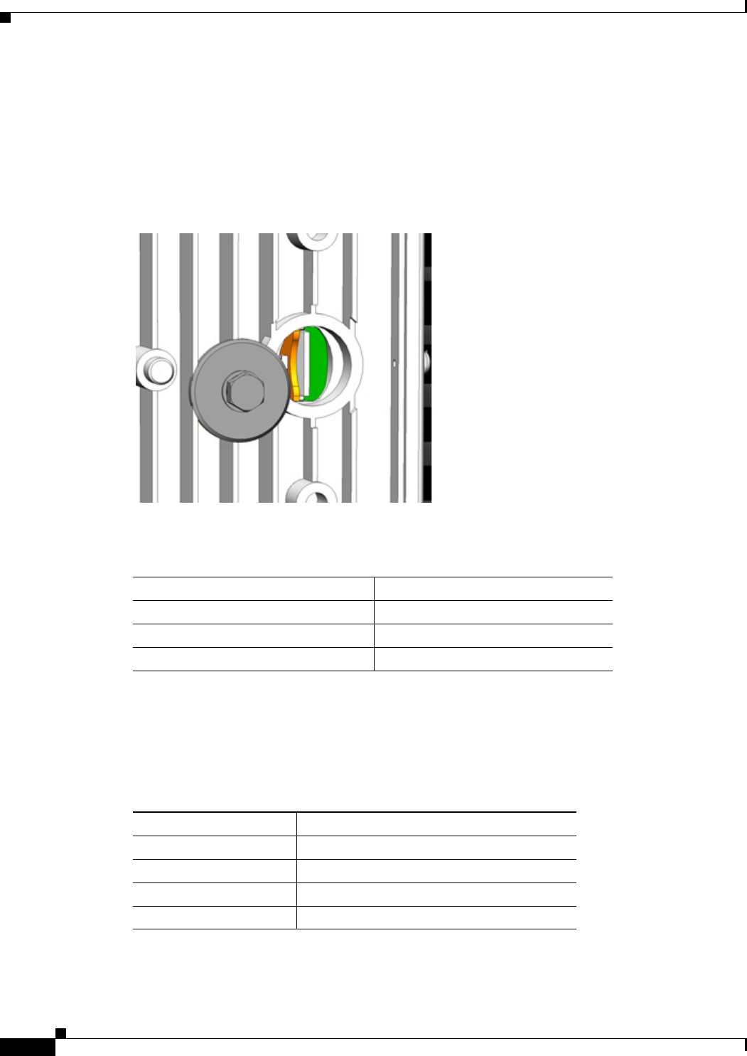
Cable Port Seals
Unused router ports are sealed with a liquid-tight cover (PG13) to protect the router interior from
environmental elements.
Caution The router should not be installed unless all unused chassis cable ports are sealed. Leaving chassis ports
unsealed can damage the router.
Figure 2-10 Cable Port Seal
Table 2-8 Supported Cisco Cable Glands
Cisco Product ID Description
CGR-IP67GLAND Contains 1 gland
Specification Description
Size PG 13
Cable diameters: 0.20-0.35 inches (5.08-8.89 mm)
Environmental Liquid Tight Type 4x & IP67
Seal guaranteed up to 150 psig (10 bar)
Flame protected
DEC. 2011—EFT REVIEW DRAFT—CISCO CONFIDENTIAL
2-15
Cisco 1240 Connected Grid Router Hardware Installation Guide
OL-12345-01
Chapter 2 Router Hardware Description
Hardware Features Detailed Description
Console Port
The router features a single, asynchronous console port (see Figure 2-4 and Figure 2-11) for connecting
a console or PC directly to the router. To configure the router locally, using the command-line interface
(CLI), you must establish a connection to the router with a terminal session.
Caution This port does not support cable glands and therefore the router interior is exposed to environmental
elements while the port is in use. This port should be exposed only during active terminal sessions with
the router and should never be left unattended when exposed.
Note The router also supports wireless console connections with an internal Short-Range Access Point.
Console Port Default Settings
The console port does not support hardware flow control. The default settings for the port are:
9600 baud, 8 data bits, no parity, and 1 stop bit.
Connecting to the Console Port
Detailed information about connecting and using the console port is in the chapter Installing the Router.
Figure 2-11 Console Port Detail
Specifications
Specification Description
Connector type RJ-45
Transceiver RS-232
Cable type EIA RJ-45
Pinout See Connector and Cable Specifications
DEC. 2011—EFT REVIEW DRAFT—CISCO CONFIDENTIAL
2-16
Cisco 1240 Connected Grid Router Hardware Installation Guide
OL-12345-01
Chapter 2 Router Hardware Description
Hardware Features Detailed Description
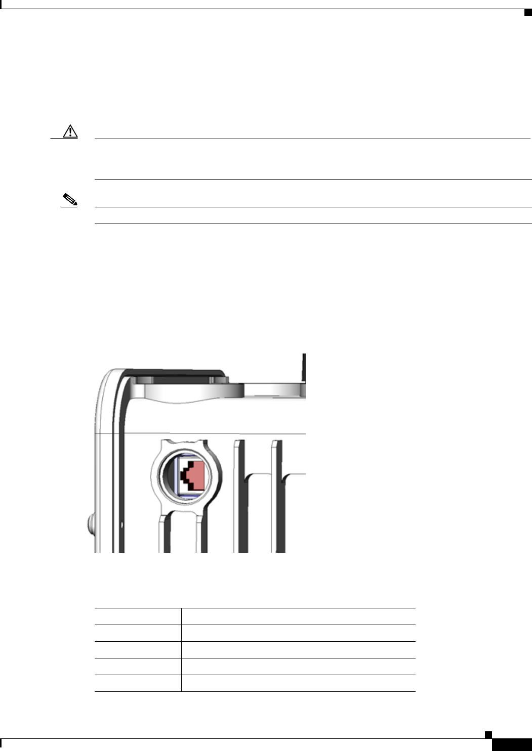
SD Flash Memory Module
The router supports one Cisco Secure Digital (SD) flash memory module (see Figure 2-5 and
Figure 2-12), which stores router software, configurations, and network data. For detailed information
on using the SD flash memory module with the router, see the chapter Using the SD Flash Memory
Module.
Figure 2-12 SD Flash Memory Slot Detail
Table 2-9 lists the supported Cisco SD modules; you must use a supported module with the router.
Specifications
Table 2-9 Supported SD Flash Modules
Cisco Part Number1
1. At FCS, these internal part numbers must be replaced with customer-facing Product ID (PID)
numbers. (PIDs not available yet in InBiz. November 29, 2011.)
Size
16-3704-01 1 GB
16-3795-01 2 GB
16-3798-01 4 GB
Specification Description
Installation Supports online insertion and removal (OIR)
Socket type 14-pin
Power (from router) +3.3 V_STBY
Voltage ramp rate range 1 mS – 100 mS

DEC. 2011—EFT REVIEW DRAFT—CISCO CONFIDENTIAL
2-17
Cisco 1240 Connected Grid Router Hardware Installation Guide
OL-12345-01
Chapter 2 Router Hardware Description
Hardware Features Detailed Description
100BASE-T Fast Ethernet Connector
The router feature an external Fast Ethernet (FE) connector (see Figure 2-7) that enables you to connect
the router to an Ethernet hub or switch without opening the chassis. The connector is connected to one
of the four Fast Ethernet Ports inside the router chassis.
Specifications
Protective Vent
The protective vent on the router base (see Figure 2-7) relieves pressure buildup inside the router chassis
that can be caused by changing temperatures in the router installation environment. This prevents
pressure from building up and damaging enclosure seals, exposing sensitive components to water. The
vent also protects the router interior from dust, dirt, water, and other environmental elements.
AC Power Supply
The router has two power sources, the AC power supply and the battery backup units.
The AC power supply connector on the router base (see Figure 2-7) is the connection from the to AC
power. If AC power is longer being supplied to the router, the battery backup units will continue to
supply power to the router until power is restored. For details about how the battery backup units
operate, see the chapter Installing Battery Backup Units.
Specifications
Specification Description
Connector type RJ-45, ODVA-compliant
Copper Ethernet
Cable type for connection to internal FE port Category 5 RJ-45 to RJ-45
Cable type for connection to Ethernet Category 5 or higher Ethernet
Specification Description
Input voltage 1-phase, two wire (line and neutral)
100-240 Vrms AC +/-10
Output 40W
DC output voltage 12V/3.5A, 3.3V/0.68A
Efficiency 20% load: 81%
50% load: 85%
100% load: 82%
Cooling Convection, conduction
Operating temperature range -40C to 85C
DEC. 2011—EFT REVIEW DRAFT—CISCO CONFIDENTIAL
2-18
Cisco 1240 Connected Grid Router Hardware Installation Guide
OL-12345-01
Chapter 2 Router Hardware Description
Hardware Features Detailed Description
Router Hardware Interior Features
This section includes detailed information about the interior hardware features illustrated in Router
Hardware Overview, page 2-2, and contains the following topics:
• Alarm Port, page 2-18
• Connected Grid Module Slots, page 2-19
• Reset Buttons, page 2-21
• Fast Ethernet Ports, page 2-22
• Gigabit Ethernet Ports, page 2-22
• Serial Ports, page 2-23
• Small Form-Factor Pluggable (SFP) Ports, page 2-24
• IRIG-B Timing Port, page 2-26
• USB Ports, page 2-27
• Memory, page 2-29
• GPS Module, page 2-29
• Short-Range Access Point, page 2-32
Alarm Port
Note Currently not supported. This hardware feature will be supported in a future software release.
Figure 2-13 Router Alarm Port
Attach the alarm port (see Figure 2-13) to an alarm system to monitor software events and errors, and
supports two alarm inputs and two alarm outputs.
The alarm-trigger setting determines when an alarm is sent to the attached alarm system.
Input Alarm Trigger Settings
• Open—The open setting indicates that the normal router operating condition has an electrical
current passing through the alarm circuits (DRY contact closed). If this electrical current is no
longer detected (DRY contact open), an alarm is generated.
DEC. 2011—EFT REVIEW DRAFT—CISCO CONFIDENTIAL
2-19
Cisco 1240 Connected Grid Router Hardware Installation Guide
OL-12345-01
Chapter 2 Router Hardware Description
Hardware Features Detailed Description
• Closed—The closed setting indicates that the normal router operating condition is that no electrical
current is passing through the alarm circuits (DRY contact open). If an electrical current is detected
(DRY contact closed), an alarm is generated.
Output Alarm Trigger Settings
• Normally Open (NO)—This setting depends on the pinout of the cable that is connected to the
alarm port. See the appendix Connector and Cable Specifications for details.
• Normally Closed (NC)—This setting depends on the pinout of the cable that is connected to the
alarm port. See the appendix Connector and Cable Specifications for details.
If interfaces fail or other non-fatal errors occur, the alarm port does not respond. Continue to use SNMP
to manage these types of errors.
Note Due to the RJ-45 pin spacing, the alarm port does not support AC signaling.
Specifications
Connected Grid Module Slots
The router has four module slots to support installation of up to four compatible Cisco Connected Grid
modules, for additional router WAN and LAN interfaces. Modules should be installed in the slots
according to the module slot numbers shown Figure 2-14. For more information about installing
Cisco Connected Grid modules, see the corresponding installation and configuration guide for each
module.
Module Numbering
The router uses module numbering to identify the integrated and modular router components. Some
system software commands refer to the module numbers.
• Module 1 is the router supervisor engine (located on the CPU motherboard)
• Module 2 is the router’s integrated Ethernet switch module, which has four Fast Ethernet ports and
two Gigabit Ethernet ports.
• Modules 3-6 are Connected Grid modules installed in the router module slots with the
corresponding number (see Figure 2-14).
Specification Description
Connector type RJ-45
Alarm input 8 volts @ 1 mA
Alarm output 30 volts @ 1 A
DEC. 2011—EFT REVIEW DRAFT—CISCO CONFIDENTIAL
2-20
Cisco 1240 Connected Grid Router Hardware Installation Guide
OL-12345-01
Chapter 2 Router Hardware Description
Hardware Features Detailed Description
Figure 2-14 Router Module Slot Numbering
DEC. 2011—EFT REVIEW DRAFT—CISCO CONFIDENTIAL
2-21
Cisco 1240 Connected Grid Router Hardware Installation Guide
OL-12345-01
Chapter 2 Router Hardware Description
Hardware Features Detailed Description
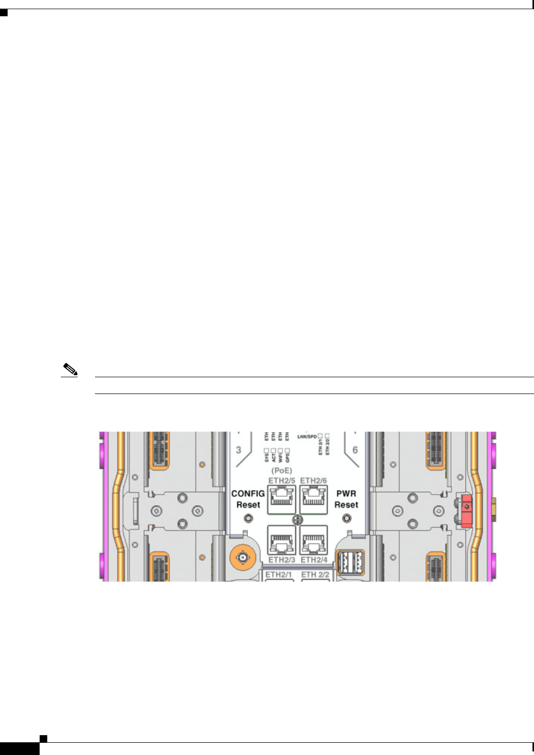
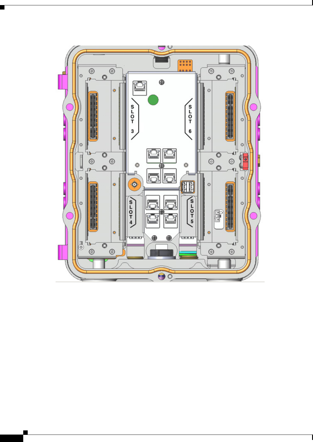
Reset Buttons
Figure 2-15 Router Reset Buttons
Use power and reset buttons as follows:
• The CONFIG Reset button resets the router to a the system default factory configuration and
reloads the router.
• The PWR Reset button cycles the system but does not power off the router.
For detailed instructions on using these buttons, see the chapter Installing the Router.
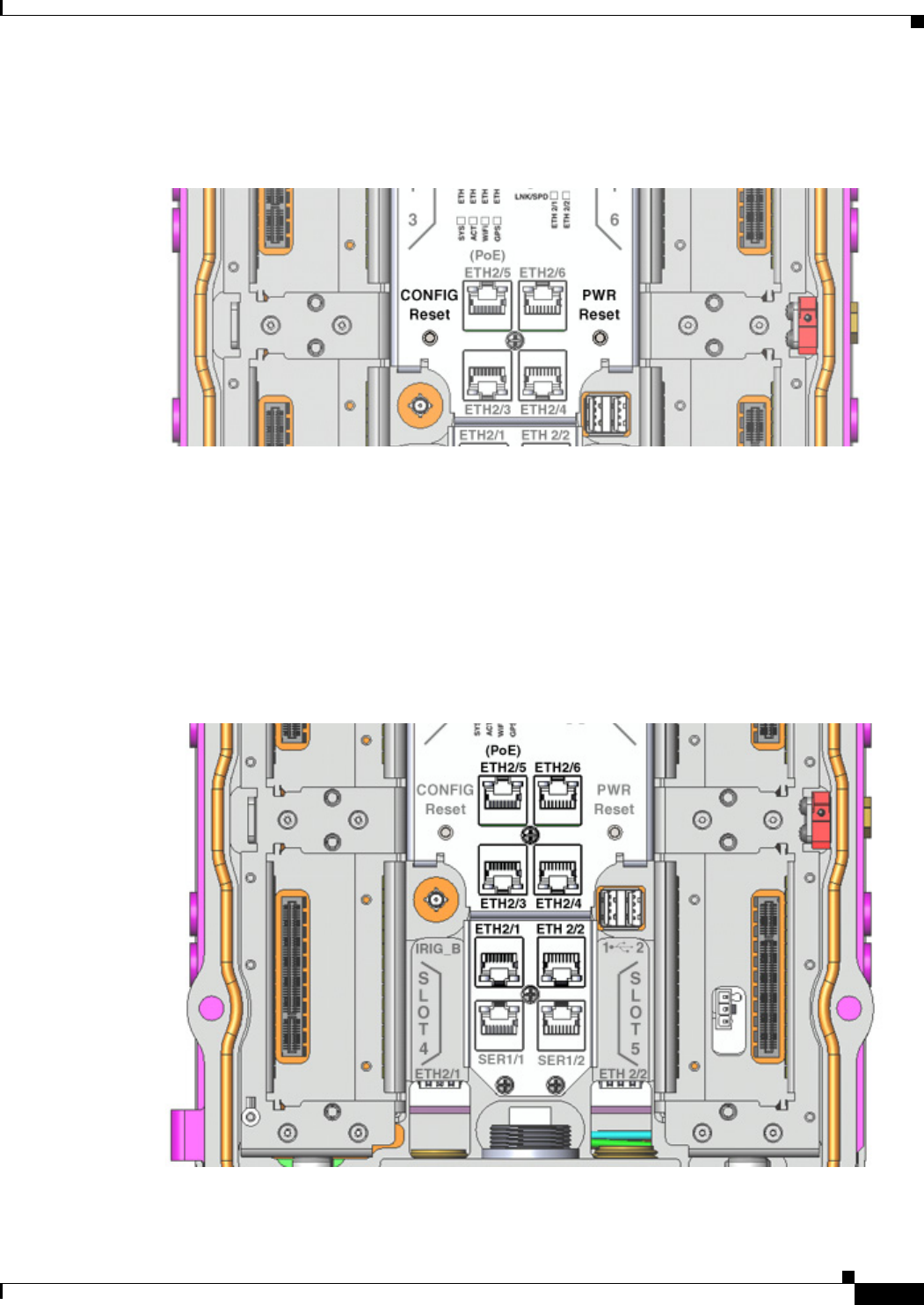
Ethernet Ports
Figure 2-16 Router Ethernet Ports

DEC. 2011—EFT REVIEW DRAFT—CISCO CONFIDENTIAL
2-22
Cisco 1240 Connected Grid Router Hardware Installation Guide
OL-12345-01
Chapter 2 Router Hardware Description
Hardware Features Detailed Description
Ethernet Connections
The established Ethernet standard is IEEE 802.3. The router supports the following Ethernet
implementations:
• 1000BASE-T—1000 Mbps full-duplex transmission over a Category 5 or better unshielded
twisted-pair (UTP) cable. Supports the Ethernet maximum length of 328 feet (100 meters).
• 100BASE-T—100 Mbps full-duplex transmission over a Category 5 or better unshielded
twisted-pair (UTP) cable. Supports the Ethernet maximum length of 328 feet (100 meters).
• 10BASE-T—10 Mbps full-duplex transmission over a Category 5 or better unshielded twisted-pair
(UTP) cable. Supports the Ethernet maximum length of 328 feet (100 meters).
Fast Ethernet Ports
The router features four Fast Ethernet (FE) ports that can be connected to an Ethernet hub or switch. The
ports are labeled as follows (see Figure 2-16):
• ETH 2/3
• ETH 2/4
• ETH 2/5
• ETH 2/6
Note Although port ETH 2/5 is labeled PoE, this port does not currently support Power over Ethernet (PoE).
Specifications
Gigabit Ethernet Ports
The router features two Gigabit Ethernet (GE) ports that can be connected to an Ethernet hub or switch.
The ports are labeled as follows (see Figure 2-16):
• ETH 2/1
• ETH 2/2
Note Interfaces ETH 2/1 and ETH 2/2 are also used by the Small Form-Factor Pluggable (SFP) Ports. For
more information about how these ports are used together, see Combo Ports, page 2-26.
The GE ports automatically detect the type of any connected cable (fiber or copper) and then switch to
the corresponding mode (fiber or copper). When both cables types are connected to the router, the first
cable that establishes a link is enabled.
Specification Description
Connector type RJ-45
Cables Category 5 or higher
Interface speed 10BASE-T and 100BASE-TX
Time stamp IEEE 1588
Pinouts See Connector and Cable Specifications
DEC. 2011—EFT REVIEW DRAFT—CISCO CONFIDENTIAL
2-23
Cisco 1240 Connected Grid Router Hardware Installation Guide
OL-12345-01
Chapter 2 Router Hardware Description
Hardware Features Detailed Description
Specifications
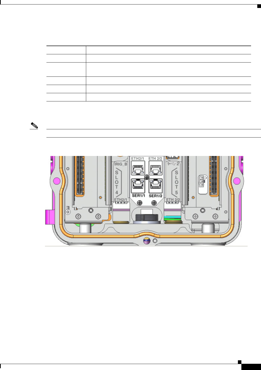
Serial Ports
Note Currently not supported. This hardware feature will be supported in a future software release.
Figure 2-17 Router Serial Ports
The router has two serial ports that support the following modes (selected with system software
commands):
• RS232
• RS422
• RS485
The ports are labeled as follows (see Figure 2-17):
• SER 1/1
• SER 1/2
Specification Description
Connector type RJ-45 (Copper mode)
Cables Optical fiber
Category 5, 5e, 6 UTP
Interface speed 100BASE-TX and 1000BASE-T
Time stamp IEEE 1588
Pinouts See Connector and Cable Specifications
DEC. 2011—EFT REVIEW DRAFT—CISCO CONFIDENTIAL
2-24
Cisco 1240 Connected Grid Router Hardware Installation Guide
OL-12345-01
Chapter 2 Router Hardware Description
Hardware Features Detailed Description
Specifications
Small Form-Factor Pluggable (SFP) Ports
Figure 2-18 Router SFP Ports
Specification RS232 RS422 RS485
Connector type RJ-45
Cable Cisco serial transition cable that matches the signaling protocol
Pinouts See Connector and Cable Specifications
Signaling Single-ended Differential Differential
Max. drivers 1 1 32
Max. receivers 110 32
Operating mode Full duplex Half duplex
Full duplex
Half duplex
Full duplex
Network topology Point-to-point Multidrop Multipoint
Max. distance (standard) 15 m 1200 m 1200 m
Max speed
(at 12 m/1200 m)
20 Kbps/1 Kbps 10 Mbps/100 Kbps 35 Mbms/100 Kbps
Max. slew rate 30 V/ìs NA NA
Receiver input resistance 3..7 kÙ 4 kΩ12 kΩ
Driver load impedance 3..7 kÙ 100 Ù 54 Ù
Receiver input sensitivity ±3 V ±200 mV ±200 mV
Receiver input range ±15 V ±10 V –7..12 V
Max. driver output voltage ±25 V ±6 V –7..12 V
Min. driver output voltage (load) ±5 V ±2.0 V ±1.5 V
Pinouts See Connector and Cable Specifications
DEC. 2011—EFT REVIEW DRAFT—CISCO CONFIDENTIAL
2-25
Cisco 1240 Connected Grid Router Hardware Installation Guide
OL-12345-01
Chapter 2 Router Hardware Description
Hardware Features Detailed Description
The router features two fiber optical SFP ports that support optional Cisco rugged SFP modules for
Gigabit Ethernet connections. The ports are labeled as follows (see Figure 2-18):
• ETH 2/1
• ETH 2/2
Note Interfaces ETH 2/1 and ETH 2/2 are also used by the Gigabit Ethernet Ports. For more information about
how these ports are used together, see Combo Ports, page 2-26.
Hot Swapping SFP Modules
The SFP modules can be installed or removed while the router is on and operating normally.
Supported SFPs
Table 2-10 lists the supported SFP modules.
Note See the Cisco 1000 Series Connected Grid Routers Release Notes for the most recent information about
supported hardware and software.
Specifications
Table 2-10 Supported SFP Modules
Cisco Product ID Description
GLC-SX-MM-RGD 1000BASE-SX short wavelength; rugged
GLC-LX-SM-RGD 1000BASE-LX/LH long wavelength; rugged
GLC-FE-100LX-RGD 100BASE-LX10 SFP
GLC-FE-100FX-RGD 100BASE-FX SFP
GLC-ZX-SM-RGD 1000BASE-ZX extended distance; rugged
Specification Description
Connector type RJ-45
Copper Interface Full-duplex 10BASE-T, 100BASE-TX, 1000BASE-T
Fiber SFP modules:
• 1000 Mbps 8B/10B coding
• 100 Mbps 4B/5B coding.
Pinouts See Connector and Cable Specifications
DEC. 2011—EFT REVIEW DRAFT—CISCO CONFIDENTIAL
2-26
Cisco 1240 Connected Grid Router Hardware Installation Guide
OL-12345-01
Chapter 2 Router Hardware Description
Hardware Features Detailed Description
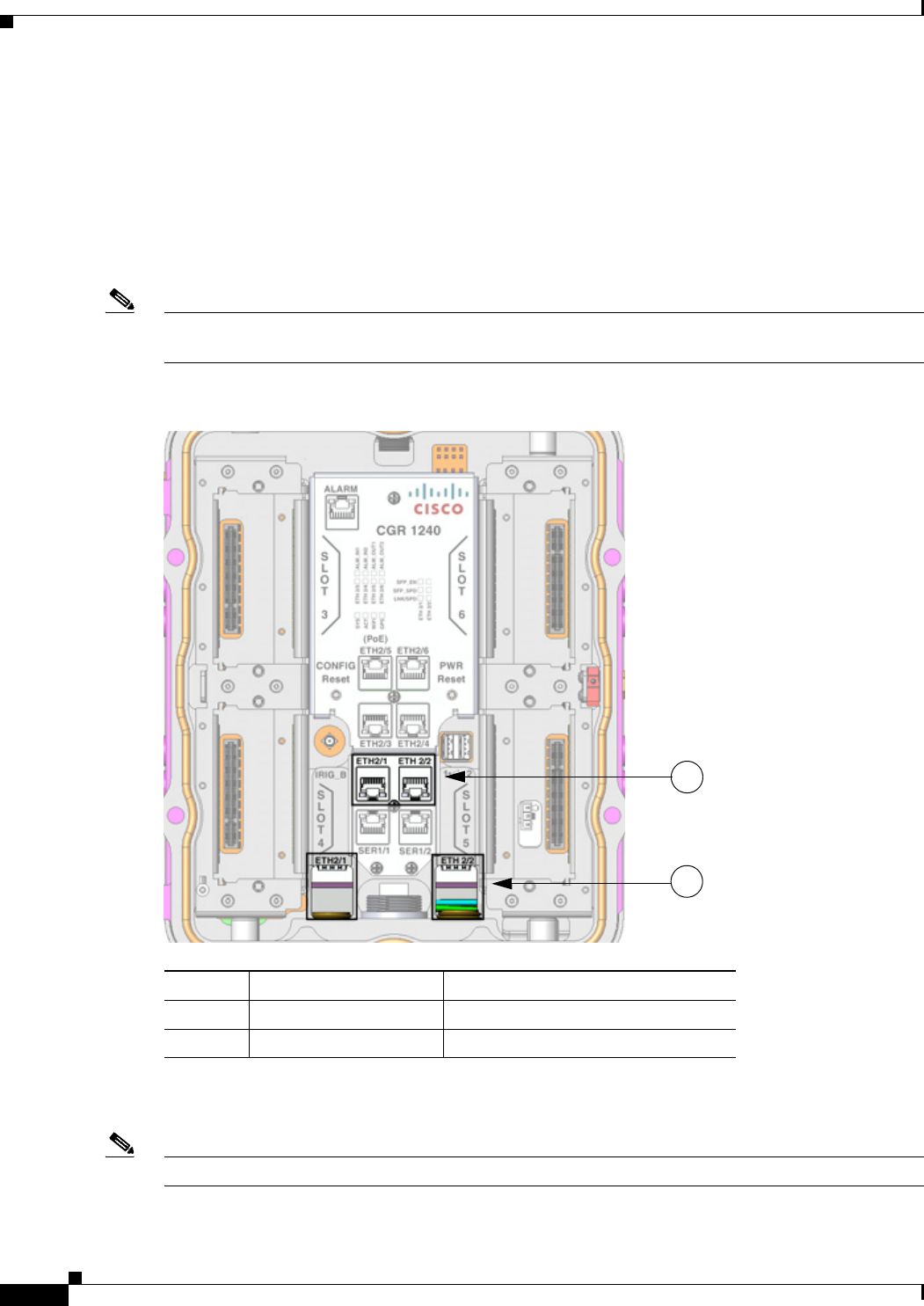
Combo Ports
The two Gigabit Ethernet Ports and the two Small Form-Factor Pluggable (SFP) Ports ports are labeled
identically (ETH 2/1 and ETH 2/2) because the SFP and GE interfaces share physical ports on the router.
The Gigabit Ethernet ports support copper GE connections and the SFP modules support fiber optic GE
connections. Only one instance of each interface (ETH 2/1 and ETH 2/2) can be in use at any time.
These ports automatically detect the type of any connected cable (fiber or copper) and then switch to the
corresponding mode (fiber or copper)
Note If connections are made to both interfaces of the same name (ETH 2/1 or ETH 2/2), only the first
connection that establishes a link is enabled.
Figure 2-19 GE Ports and SFP Ports Share Interfaces ETH 2/1 and ETH 2/2
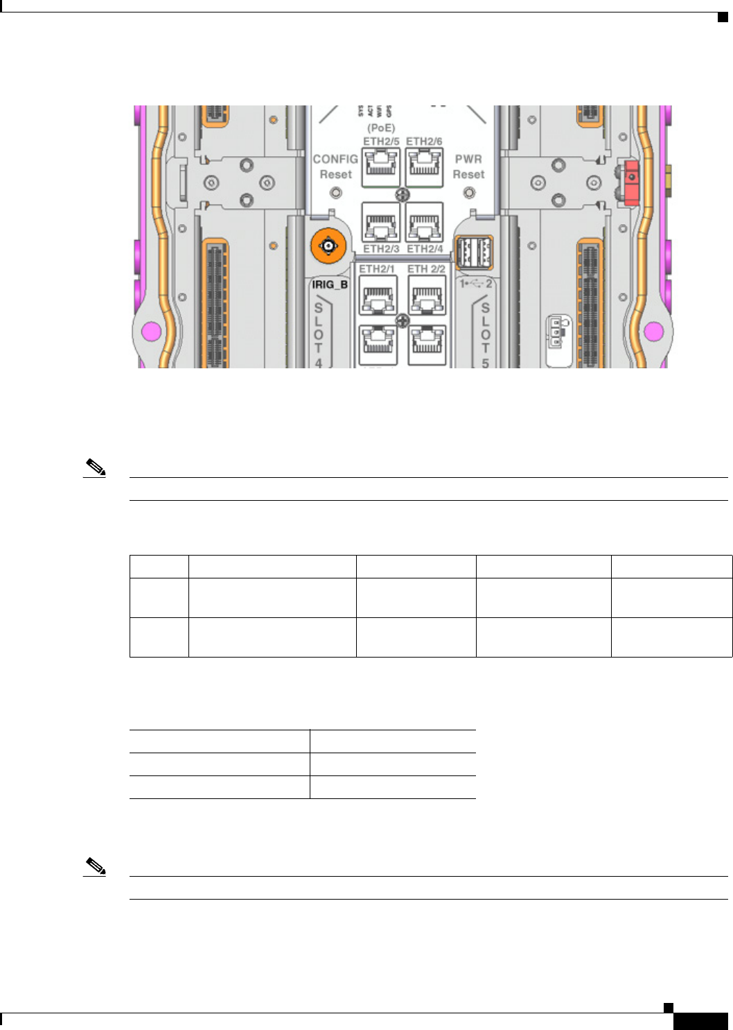
IRIG-B Timing Port
Note Currently not supported. This hardware feature will be supported in a future software release.
Items Description Gigabit Ethernet Connection Type
1Gigabit Ethernet ports Copper
2SFP module ports Fiber optic
1
2
DEC. 2011—EFT REVIEW DRAFT—CISCO CONFIDENTIAL
2-27
Cisco 1240 Connected Grid Router Hardware Installation Guide
OL-12345-01
Chapter 2 Router Hardware Description
Hardware Features Detailed Description
Figure 2-20 Router IRIG-B Timing Port
The router features a single IRIG-B timing port (see Figure 2-20), which provides serial formatted time
codes to an optional connected device. IRIG-B output provides standard time codes to so timing devices
can correlate time information with network devices. The router integrated GPS provides the time
information that is provided by this interface.
Note The IRIG-B timing port supports timing output only.
Specifications
USB Ports
Note Currently not supported. This hardware feature will be supported in a future software release.
Table 2-11 Supported IRIG Serial Time Code Formats
Format Modulations Carrier Frequency Code Expression Interface
B000 DC Level Shift (DCLS)
pulse-width coded
None BCD time of year,
CF and SBS
RS232/RS485
B120 Amplitude Modulation
(AM)
1kHz sine wave BCD time of year,
CF and SBS
50 ohms BNC
Specification Description
Connector type SMB coaxial RF
Supported Code Formats IRIG-B000 and B123
DEC. 2011—EFT REVIEW DRAFT—CISCO CONFIDENTIAL
2-28
Cisco 1240 Connected Grid Router Hardware Installation Guide
OL-12345-01
Chapter 2 Router Hardware Description
Hardware Features Detailed Description
Figure 2-21 Router USB Ports
The router features two standard USB 2.0 ports for connecting and powering optional USB peripheral
devices. These ports also support USB devices that are powered by an external source, such as an AC
adapter or batteries, when the connected device consumes 2.5 or less power per port.
These ports are labeled as follows (see Figure 2-21)
• 1 2
The USB ports operate at the following speeds:
• 1 Mbps
• 12 Mbps
• 480 Mbps
Connection Considerations
• Depending on the USB devices you connect to these ports, you might require a USB extension cable
to connected devices to these ports.
• To prevent connected USB devices from being stolen or accidently removed, secure any connected
USB device with a locking mechanism designed for this purpose
Specifications
Specification Description
USB Port Type Type A
USB Device Types Supported USB 1.1, USB 2.0
Power Output 2.5W (+5V +/-5% @ 500mA) per port

DEC. 2011—EFT REVIEW DRAFT—CISCO CONFIDENTIAL
2-29
Cisco 1240 Connected Grid Router Hardware Installation Guide
OL-12345-01
Chapter 2 Router Hardware Description
Hardware Features Detailed Description
Memory
SD Flash Memory
See SD Flash Memory Module, page 2-16.
SDRAM
The router features 1 Gb of double data rate (DDR) SDRAM.
Boot Flash
The router features 16 Mb of boot flash memory, consisting of two 8 Mb Serial Peripheral Interface
(SPI) flash devices. The boot flash supports the Common Flash Interface (CFI) standard and CFI
Descriptions should be taken into account when configuring router timeout values for router access
operations, such as erase or program operations.
DC Power for External Devices
The router provides features a 4-pin Micro-Fit 3.0 power connector to support a compatible external
device, such as an optional non-Cisco wireless module installed on the router exterior.
More Information
• For detailed instructions on how to install a non-Cisco module and connect to this DC power
connector, see the chapter Installing Non-Cisco Modules.
• Pinouts for the Molex Micro-Fit 3.0 connector are in the appendix Connector and Cable
Specifications.
Specifications
GPS Module
The router has an internal Global Positioning System (GPS), which provides time synchronization
throughout the field area network, providing precise to enable efficient power measurement and
distribution. The GPS also provides the router location information to the network management system.
GPS Operating Modes
The router GPS operates in the following modes, based on the router operating status:
• Run mode—Run mode is the normal GPS operating mode, during which the GPS continually
provides location and time information to the router.
Specification Description
Voltage 12 VDC +/-5%
Maximum Power 12 W (continuous)
DC Power Connector Molex Micro-Fit 3.0

DEC. 2011—EFT REVIEW DRAFT—CISCO CONFIDENTIAL
2-30
Cisco 1240 Connected Grid Router Hardware Installation Guide
OL-12345-01
Chapter 2 Router Hardware Description
Hardware Features Detailed Description
• Monitor mode—The GPS operates in monitor mode when you upgrade the firmware that is stored
in the SD Flash Memory Module.
• Standby mode—When the router AC power supply fails or is not present, and the battery backup
unit is providing power to the router, the GPS operates in standby mode. The GPS receiver is
disabled but the GPS RAM and the real-time clock remain active. In this mode, the GPS RAM stores
the GPS almanac, ephemeris, and last position.
–
When the GPS is in standby mode for less than two hours, it performs a hot start when normal
router power is restored.
–
When the GPS is in standby mode for more than two hours, it performs a warm start when
normal router power is restored.
GPS LED
You can view the GPS LED to determine the GPS state and whether or not it is successfully connected
to a GPS satellite. For information on the GPS LED, see the chapter Router LED Locations and States.
GPS Timing Messages
GPS positioning messages contain a timestamp which can be up to two seconds in the past, so the router
uses data contained in timing messages described Table 2-12 as the source of time for the GPS.
Note The GPS time must calculate in the Universal Coordinated Time (UTC) offset, which is used to set the
local time.
Acquiring the Correct Time
Take the following steps to ensure the GPS acquires an accurate time:
Step 1 To eliminate UTC offset, confirm that the almanac is complete and the receiver is generating 3D fixes.
Step 2 Confirm that the GPS receiver is configured for the late PPS (Pulse-Per-Second) option (the receiver
outputs one PPS for a 3D fix).
Step 3 Capture the time from TSIP packet 0x41 or TSIP packet 0x8F-20.
Step 4 On the next PPS, add 1 to the whole second captured in Step 3 to adjust to the correct time.
Table 2-12 GPS Timing Protocols and Messages
Protocol Name Message Type Containing Time Information
TSIP (Trimble Standard Interface Protocol) Packets 41 and 8F-21.
TAIP (Trimble ASCII Interface Protocol) TM messages
NMEA (National Marine Electronics Association) ZDA message.

DEC. 2011—EFT REVIEW DRAFT—CISCO CONFIDENTIAL
2-31
Cisco 1240 Connected Grid Router Hardware Installation Guide
OL-12345-01
Chapter 2 Router Hardware Description
Hardware Features Detailed Description
Specifications
Related Commands
Use the commands in this section to see the GPS current time and location.
Use the show gps time command to display the current GPS time:
cgr-1000# show gps time
8:46:9.923 UTC Fri Sep 11 2011
Use the show gps location command to display the GPS latitude and longitude:
cgr-1000# show gps location
Latitude: 37.4090637
Longitude -121.9523598
Specification Description
Channels 12
Tracking sensitivity -160 dBm
Acquisition sensitivity -148 dBM
Fast TTFF (Cold start) 38 sectons
Error correction Space Based Augmentation Systems (SBAS)
Timing protocols NMEA (0183 v3.0 Messages), TSIP, TAIP
Serial ports 2
For pinouts, see the appendix Connector and Cable
Specifications
Pulse Per Second (PPS) Specifications
PPS CMOS output 1
PPS Output Mode Always on (Early PPS)
PPS pulse width (configurable) 4.2 microseconds (default)
PPS polarity (configurable) -1 positive (default)
DEC. 2011—EFT REVIEW DRAFT—CISCO CONFIDENTIAL
2-32
Cisco 1240 Connected Grid Router Hardware Installation Guide
OL-12345-01
Chapter 2 Router Hardware Description
Hardware Features Detailed Description
Short-Range Access Point
The router features an integrated, short-range WiFi access point to support a wireless console connection
to the router. Generally, the router is installed on a pole above the ground, which makes a wired console
connection impractical during router operation.
The WiFi connection is available only when the system software is operating. If the system software is
not operating, you cannot use the WiFi connection to connect to or administer the router.
Related Commands
Use the show hardware internal wifi command to display details about the state of the integrated WiFi
access point.
show hardware internal wifi
Real-Time Clock (RTC)
The router features an integrated real-time clock (RTC) with battery backup that supplies the system
software with accurate date and time information. The integrated router GPS compares the current RTC
time with the time at which it last received a valid signal to ensure accurate timekeeping on the router.
The RTC value can be synchronized with other time counters in the network, for example the system
time maintained by Precision Time Protocol (PTP).
When the router is powered on using the Reset Buttons, the RTC sets the router memory controller and
clock frequency.
RTC Battery
The RTC includes battery backup for the date and time when the router is not receiving any power.
Specifications
show hardware internal wifi
{event-history | logging-levels | port
| registers | sw-state}
Enter the keyword for the information you want to see.
• event-history—Displays a list of events for the integrated
access point.
• logging-levels—Displays the current logging levels for
the integrated access point.
• port—Displays port information (per port) for the
integrated access point.
• registers—Displays the register values for the integrated
access point.
• sw-state
Specification Description
Battery type High-capacity lithium (550 mAh)
Battery life span 10 years
Supported interrupts Time-of-day alarms (Range: 1/second – 1/month)

DEC. 2011—EFT REVIEW DRAFT—CISCO CONFIDENTIAL
2-33
Cisco 1240 Connected Grid Router Hardware Installation Guide
OL-12345-01
Chapter 2 Router Hardware Description
Hardware Features Detailed Description
Temperature Sensor
The router hardware features an internal temperature sensor used by the router software to monitor the
system operating temperature. The router can be configured to generate alerts when the temperature falls
outside of a user-defined temperature range. The router can also be configured to store historical
temperature data.
For more information about monitoring and storing router temperature data, see the Cisco 1000 Series
Connected Grid Routers Software Configuration Guide.
Periodic rates (Range: 122 us – 500 ms)
End-of-update-cycle notifications
Specification Description

DEC. 2011—EFT REVIEW DRAFT—CISCO CONFIDENTIAL
2-34
Cisco 1240 Connected Grid Router Hardware Installation Guide
OL-12345-01
Chapter 2 Router Hardware Description
Hardware Features Detailed Description

CHAPTER
DEC. 2011—EFT REVIEW DRAFT—CISCO CONFIDENTIAL
3-1
Cisco 1240 Connected Grid Router Hardware Installation Guide
OL-26223-01
3
Installation Safety and Site Preparation
This chapter contains safety and site preparation information that you must read before installing the
router, and includes these sections:
• Safety Recommendations, page 3-1
• Safety with Electricity, page 3-1
• Preventing Electrostatic Discharge Damage, page 3-2
• Safety Warnings, page 3-2
• Site Requirements, page 3-3
• Power Guidelines and Requirements, page 3-4
• Preparing for Network Connections, page 3-5
• Required Tools and Equipment for Installation and Maintenance, page 3-7
Safety Recommendations
Follow these guidelines to ensure general safety:
• Keep the chassis area clear and dust-free during and after installation.
• Keep tools and chassis components away from walk areas.
• Do not wear loose clothing that could get caught in the chassis. Fasten your tie or scarf and roll up
your sleeves.
• Wear safety glasses when working under conditions that might be hazardous to your eyes.
• Do not perform any action that creates a hazard to people or makes the equipment unsafe.
Safety with Electricity
Follow these guidelines when working on equipment powered by electricity:
• Read all warnings in the section Safety Warnings, page 3-2.
• Locate the emergency power-off switch for you installation location. If an electrical accident occurs,
you can quickly turn off the power.
• Disconnect all power before doing the following:
–
Installing or removing a chassis

DEC. 2011—EFT REVIEW DRAFT—CISCO CONFIDENTIAL
3-2
Cisco 1240 Connected Grid Router Hardware Installation Guide
OL-26223-01
Chapter 3 Installation Safety and Site Preparation
Preventing Electrostatic Discharge Damage
–
Working near power supplies
• Look carefully for possible hazards in your work area, such as moist floors, ungrounded power
extension cables, frayed power cords, and missing safety grounds.
• Do not work alone if hazardous conditions exist.
• Never assume that power is disconnected from a circuit. Always check.
• Never open the enclosure of the router’s internal power supply.
• If an electrical accident occurs, proceed as follows:
–
Use caution; do not become a victim yourself.
–
Turn off power to the device.
–
If possible, send another person to get medical aid. Otherwise, assess the victim’s condition and
then call for help.
–
Determine if the person needs rescue breathing or external cardiac compressions; then take
appropriate action.
Preventing Electrostatic Discharge Damage
Electrostatic discharge (ESD) can damage equipment and impair electrical circuitry. It can occur if
electronic printed circuit cards are improperly handled and can cause complete or intermittent failures.
Always follow ESD prevention procedures when removing and replacing modules:
• Ensure that the router chassis is electrically connected to earth ground.
• Wear an ESD-preventive wrist strap, ensuring that it makes good skin contact. Connect the clip to
an unpainted surface of the chassis frame to channel unwanted ESD voltages safely to ground. To
guard against ESD damage and shocks, the wrist strap and cord must operate effectively.
• If no wrist strap is available, ground yourself by touching a metal part of the chassis.
Caution For the safety of your equipment, periodically check the resistance value of the antistatic strap. It should
be between 1 and 10 megohms (Mohm).
Safety Warnings
This section contains important safety warnings for the installation and use of the router.
Translated versions of all safety warnings are available in the safety warnings document that shipped
with your router, and which is available on Cisco.com.
Warning
IMPORTANT SAFETY INSTRUCTIONS
This warning symbol means danger. You are in a situation that could cause bodily injury. Before you
work on any equipment, be aware of the hazards involved with electrical circuitry and be familiar
with standard practices for preventing accidents. Use the statement number provided at the end of
each warning to locate its translation in the translated safety warnings that accompanied this device.
Statement 1071
DEC. 2011—EFT REVIEW DRAFT—CISCO CONFIDENTIAL
3-3
Cisco 1240 Connected Grid Router Hardware Installation Guide
OL-26223-01
Chapter 3 Installation Safety and Site Preparation
Site Requirements
Warning
In order to comply with FCC radio frequency (RF) exposure limits, antennas for this product should be
located a minimum of 7.9 in. (20 cm) or more from the body of all persons.
Statement 332
Warning
Do not operate the unit near unshielded blasting caps or in an explosive environment unless the
device has been modified to be especially qualified for such use.
Statement 364
Warning
This equipment must be externally grounded using a customer-supplied ground wire before power is
applied. Contact the appropriate electrical inspection authority or an electrician if you are uncertain
that suitable grounding is available.
Statement 366
Warning
Do not work on the system or connect or disconnect cables during periods of lightning activity.
Statement 1001
Warning
Read the installation instructions before connecting the system to the power source.
Statement 1004
Warning
This product relies on the building’s installation for short-circuit (overcurrent) protection. Ensure that
the protective device is rated not greater than 20 A.
Statement 1005
Warning
This unit is intended for installation in restricted access areas. A restricted access area can be
accessed only through the use of a special tool, lock and key, or other means of security.
Statement 1017
Warning
Only trained and qualified personnel should be allowed to install, replace, or service this equipment.
Statement 1030
Warning
Ultimate disposal of this product should be handled according to all national laws and regulations.
Statement 1040
Warning
Installation of the equipment must comply with local and national electric codes.
Statement 1074
Site Requirements
This section describes the requirements your site must meet for safe installation and operation of your
router. Ensure that the site is properly prepared before beginning installation. If you are experiencing
shutdowns or unusually high errors with your existing equipment, this section can also help you isolate
the cause of failures and prevent future problems.

DEC. 2011—EFT REVIEW DRAFT—CISCO CONFIDENTIAL
3-4
Cisco 1240 Connected Grid Router Hardware Installation Guide
OL-26223-01
Chapter 3 Installation Safety and Site Preparation
Power Guidelines and Requirements
Poletop Installation Requirements
The installation steps in this manual (Installing the Router) require that the router mounting and
installation locations, usually at the top of a power or other utility pole, have the following connections
available for basic router installation:
• AC power connection
• Fast Ethernet connection, as described in the section Ethernet Connections, page 3-5
Environmental Requirements
The location of your router is an important consideration for proper operation. Equipment placed too
close together, inadequate ventilation, and inaccessible panels can cause malfunctions and shutdowns,
and can make maintenance difficult. Plan for access to both power supply side and cable side panels of
the router.
If you are currently experiencing shutdowns or an unusually high number of errors with your existing
equipment, these precautions and recommendations may help you isolate the cause of failure and prevent
future problems.
• Always follow ESD-prevention procedures described in the Preventing Electrostatic Discharge
Damage, page 3-2 to avoid damage to equipment. Damage from static discharge can cause
immediate or intermittent equipment failure.
• Ensure that the chassis door closes securely and that all empty module slots and have filler panels
installed.
• When other equipment is installed on or connected to the router, try operating the router by itself,
if possible. Power off other equipment (such as USB devices and installed third-party modules) to
allow the router under test a maximum of cooling air and clean power.
FCC Safety Compliance Statement
The FCC, with its action in ET Docket 9608, has adopted a safety standard for human exposure to RF
electromagnetic energy emitted by FCC-certified equipment. When used with approved Cisco antennas,
Cisco products meet the uncontrolled environmental limits found in OET-65 and ANSI C95.1, 1991.
Proper operation of this radio device according to the instructions in this publication results in user
exposure substantially below the FCC recommended limits.
Power Guidelines and Requirements
• Check the power at your site to ensure that you are receiving power that is free of spikes and noise.
• Install a power conditioner if necessary.
• Verify the AC power supply includes an autorange feature to autoselect 100 V to 240 V operation.

DEC. 2011—EFT REVIEW DRAFT—CISCO CONFIDENTIAL
3-5
Cisco 1240 Connected Grid Router Hardware Installation Guide
OL-26223-01
Chapter 3 Installation Safety and Site Preparation
Preparing for Network Connections
Preparing for Network Connections
When setting up your router, consider distance limitations and potential electromagnetic interference
(EMI) as defined by the applicable local and international regulations.
Network connection considerations are provided for several types of network interfaces and are
described in the following sections:
• Ethernet Connections, page 3-5
• Serial Connections, page 3-5
Warning
To avoid electric shock, do not connect safety extra-low voltage (SELV) circuits to telephone-network
voltage (TNV) circuits. LAN ports contain SELV circuits, and WAN ports contain TNV circuits. Some
LAN and WAN ports both use RJ-45 connectors.
Statement 1021
Ethernet Connections
The IEEE has established Ethernet as standard IEEE 802.3. The router supports the following Ethernet
implementations:
• 1000BASE-X—1000 Mb/s full-duplex transmission over a Category 5 or better unshielded
twisted-pair (UTP) cable (IEEE 802.3z). Supports the Ethernet maximum length of 328 feet (100
meters).
• 1000BASE-T—1000 Mb/s full-duplex transmission over a Category 5 or better unshielded
twisted-pair (UTP) cable (IEEE 802.3ab). Supports the Ethernet maximum length of 328 feet (100
meters).
• 100BASE-TX—100 Mb/s full-duplex transmission over a Category 5 or better unshielded
twisted-pair (UTP) cable (IEEE 802.3u). Supports the Ethernet maximum length of 328 feet (100
meters).
For more information about Ethernet connections and cables, see the following chapters:
• For cable and connector pinouts, see the appendix Connector and Cable Specifications.
• For cabling instructions, see the chapter Installing the Router.
Serial Connections
Serial connections are provided by router serial ports, described in detail in the Router Hardware
Description chapter.
Before you connect a device to a serial port, you need to know the following:
• Type of device, data terminal equipment (DTE) or data communications equipment (DCE), you are
connecting to the synchronous serial interface
• Signaling standard required by the device
• Serial ports can be configured as DTE or DCE, depending on the serial cable used.

DEC. 2011—EFT REVIEW DRAFT—CISCO CONFIDENTIAL
3-6
Cisco 1240 Connected Grid Router Hardware Installation Guide
OL-26223-01
Chapter 3 Installation Safety and Site Preparation
Preparing for Network Connections
Serial DTE or DCE Devices
A device that communicates over a synchronous serial interface is either a DCE or DTE device. A DCE
device provides a clock signal that paces the communications between the device and the router. A DTE
device does not provide a clock signal. DTE devices usually connect to DCE devices. The
documentation that accompanied the device should indicate whether it is a DTE or DCE device. (Some
devices have a jumper to select either DTE or DCE mode.) Table 3-1 lists typical DTE and DCE devices.
Signaling Standards Supported
The synchronous serial ports available for the router support the EIA/TIA-232 (EIA-323) signaling
standard. You can order a Cisco DB-25 shielded serial-transition cable that has the appropriate
connector for the standard you specify. The documentation for the device should indicate the standard
used for that device. The router end of the shielded serial transition cable has a DB-25 connector, which
connects to the DB-25 port on a serial grid router WAN interface card. The other end of the serial
transition cable is available with a connector appropriate for the standard you specify.
The synchronous serial port can be configured as DTE or DCE, depending on the attached cable.
All serial ports configured as DTE require external clocking from a Channel Service Unit/Data Service
Unit (CSU/DSU) or other DCE device.
Exterior 100BASE-T Fast Ethernet Port
The router exterior Ethernet connector is compliant with Open DeviceNet Vendor Association (ODVA)
standards. Cables used with this port must also be ODVA-compliant. ODVA compliant cables and
connectors meet IP 67 ratings.
Distance Limitations
Serial signals can travel a limited distance at any given bit rate; generally, the slower the data rate, the
greater the distance. All serial signals are subject to distance limits, beyond which a signal significantly
degrades or is completely lost.
Table 3-2 lists the recommended maximum speeds and distances for each serial interface type; however,
you might get good results at speeds and distances greater than those listed, if you understand the
electrical problems that might arise and can compensate for them. For instance, the recommended
maximum rate for V.35 is 2 Mb/s, but 4 Mb/s is commonly used.
Table 3-1 Typical DTE and DCE Devices
Device Type Gender Typical Devices
DTE Male1
1. If pins protrude from the base of the connector, the connector is male.
Terminal
PC
DCE Female2
2. If the connector has holes to accept pins, the connector is female.
Modem
CSU/DSU
Multiplexer

DEC. 2011—EFT REVIEW DRAFT—CISCO CONFIDENTIAL
3-7
Cisco 1240 Connected Grid Router Hardware Installation Guide
OL-26223-01
Chapter 3 Installation Safety and Site Preparation
Required Tools and Equipment for Installation and Maintenance
Asynchronous/Synchronous Serial Module Baud Rates
The following baud-rate limitations apply to the slow-speed serial interfaces found in the
asynchronous/synchronous serial modules:
• Asynchronous interface—Maximum baud rate is 115.2 Kbps.
• Synchronous interface—Maximum baud rate is 128 kbps full duplex
Required Tools and Equipment for Installation and Maintenance
The tools and equipment you need for each hardware procedure are described as part of the procedure.
See the following chapters for detailed information on the tools and equipment you must supply for the
procedures described in the following chapters:
• Mounting the Router
• Opening the Router Chassis
• Installing Battery Backup Units
• About Router Antennas
• Installing Non-Cisco Modules
• Installing the Router
See the Cisco Connected Grid modules installation and configuration guides for instructions on how to
install or replace router modules, include the tools and equipment you must supply.
Table 3-2 Serial Signal Transmission Speeds and Distances
Distance for
EIA/TIA-232
Distance for X.21 and
V.35 Distance for USB
Rate (bps) Feet Meters Feet Meters Feet Meters
2400 200 60 4100 1250 16.4 5
4800 100 30 2050 625 16.4 5
9600 50 15 1025 312 16.4 5
19200 25 7.6 513 156 16.4 5
38400 12 3.7 256 78 16.4 5
56000 8.6 2.6 102 31 16.4 5
1544000 (T1) — — 50 15 16.4 5

DEC. 2011—EFT REVIEW DRAFT—CISCO CONFIDENTIAL
3-8
Cisco 1240 Connected Grid Router Hardware Installation Guide
OL-26223-01
Chapter 3 Installation Safety and Site Preparation
Required Tools and Equipment for Installation and Maintenance

CHAPTER
DEC. 2011—EFT REVIEW DRAFT—CISCO CONFIDENTIAL
4-1
Cisco 1240 Connected Grid Router Hardware Installation Guide
OL-26223-01
4
Opening the Router Chassis
This chapter describes how to open the Cisco CGR 1240 Router door so that you can access the interior
of the chassis, and contains these sections:
• Opening the Router Door, page 4-1
• Door Features, page 4-5
Opening the Router Door
To access the router interior, you must open the router front door. Many of the router hardware
installation tasks require you to open the router door and access the router interior. These tasks include:
• Installing Cisco Connected Grid modules
• Installing some module antenna models
• Connecting and cabling the router ports
• Installing battery backup units
• Installing a non-Cisco module on the router
• Using the power and reset buttons
• Viewing the LEDs on the router interior
Preparing to Open the Door
The router door can be opened while the router is powered on and connected to the network. Take any
safety precautions described in Safety Information, page 4-2.
Tools You Supply
You must provide a 1/2-inch (13-mm) box-end wrench or socket set to open and close the router chassis
door.
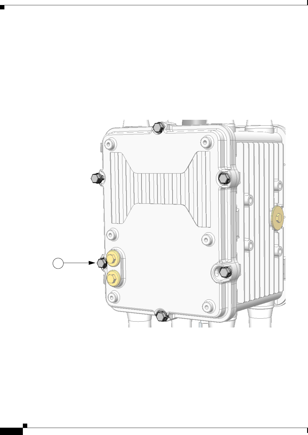
DEC. 2011—EFT REVIEW DRAFT—CISCO CONFIDENTIAL
4-2
Cisco 1240 Connected Grid Router Hardware Installation Guide
OL-26223-01
Chapter 4 Opening the Router Chassis
Opening the Router Door
Safety Information
Before performing any of the tasks in this chapter, read the safety warnings in the Installation Safety and
Site Preparation chapter.
Captive Screws
The router door features six captive screws, shown in Figure 4-1 (1).
Figure 4-1 Router Door, Showing Captive Screws
Order of Loosening and Tightening Door Screws
Cisco recommends that you loosen and tighten the door screws in the order shown in Figure 4-1.
The chassis door features an environmental seal that protects the chassis against environmental elements
when the door is closed. This seal creates pressure, which can cause the door to open suddenly when the
last screw is loosened.
1
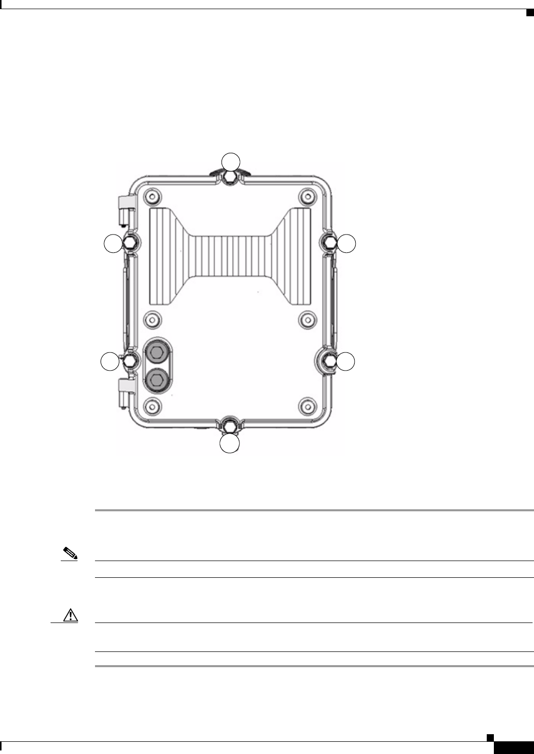
DEC. 2011—EFT REVIEW DRAFT—CISCO CONFIDENTIAL
4-3
Cisco 1240 Connected Grid Router Hardware Installation Guide
OL-26223-01
Chapter 4 Opening the Router Chassis
Opening the Router Door
• When opening the door, alternate loosening screws on each side of the chassis, in the order shown
in Figure 4-1, to evenly release the door pressure.
• When closing the door, do not tighten the screws on the hinge-side of the door first. Tightening the
screws on the hinge-side first can place too much pressure on the door hinges.
Figure 4-2 Recommended Order of Loosening and Tightening Screws
Opening the Door
Step 1 To open the door, use a box-end or socket wrench to loosen all six captive screws in the order shown in
Figure 4-1.
Note The screws cannot be removed from the door. Figure 4-3 is a detailed view of a captive screw.
Step 2 After all six screws are loose, swing the door open on the left-side hinges, as shown in Figure 4-4.
Caution The door gasket creates a seal when the door is closed, so the door might open suddenly when the last
screw is loosened.
3
2 4
5
6
1
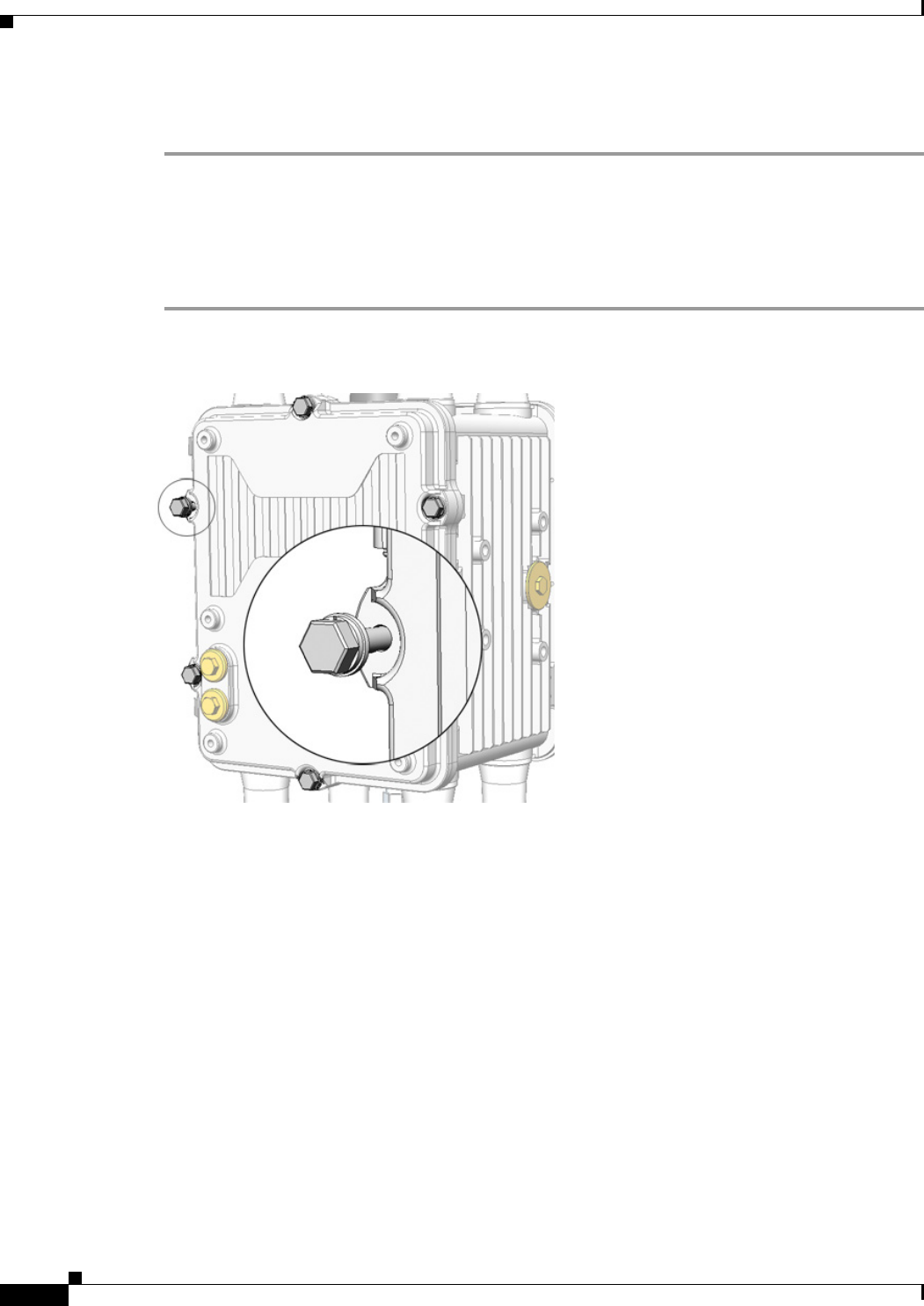
DEC. 2011—EFT REVIEW DRAFT—CISCO CONFIDENTIAL
4-4
Cisco 1240 Connected Grid Router Hardware Installation Guide
OL-26223-01
Chapter 4 Opening the Router Chassis
Opening the Router Door
Closing the Door
Step 1 Verify that the door seal is clean and that all cables are tucked back into the chassis.
Step 2 To close the door, use the wrench to evenly tighten all six screws in the order shown in Figure 4-1.
Step 3 Evenly tighten the screws again, in the order shown in Figure 4-1, this time using 6 to 7 foot-pounds of
torque.
Step 4 Replace any locking mechanism on the door.
Figure 4-3 Captive Screw Detail
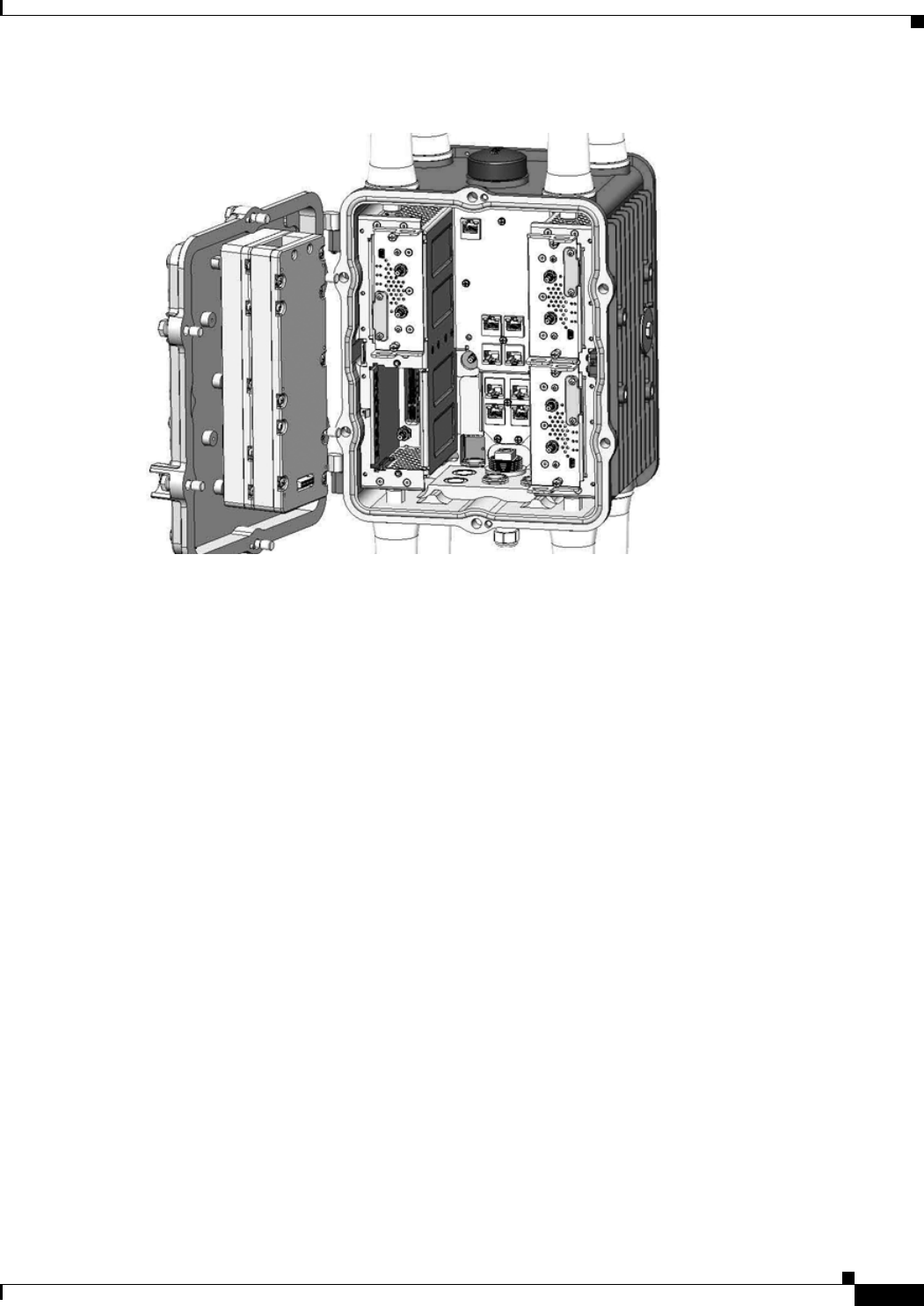
DEC. 2011—EFT REVIEW DRAFT—CISCO CONFIDENTIAL
4-5
Cisco 1240 Connected Grid Router Hardware Installation Guide
OL-26223-01
Chapter 4 Opening the Router Chassis
Door Features
Figure 4-4 Router Door Open
Door Features
This section describes these door features:
• Door Sensor, page 4-5
• Support for Exterior Door Lock, page 4-6
Door Sensor
The chassis hardware features a pressure-sensitive alarm switch, shown in Figure 4-5, which detects
when the router door opens or closes and alerts the operator to a potential security breach.
When the switch detects that the door has been opened or closed, it sends an event message to the router.
The event message is stored in the router log file.
These are examples of the door state event messages:
Sep 24 08:04 Router %$ VDC-1 %$ %FCPLMGR-2-FCPLMGR_DOOR_ALARM: door/lid has been closed
Sep 24 08:04 Router %$ VDC-1 %$ %FCPLMGR-2-FCPLMGR_DOOR_ALARM: door/lid has been open
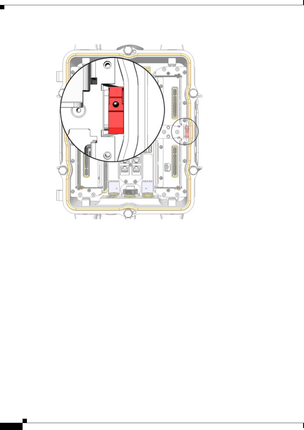
DEC. 2011—EFT REVIEW DRAFT—CISCO CONFIDENTIAL
4-6
Cisco 1240 Connected Grid Router Hardware Installation Guide
OL-26223-01
Chapter 4 Opening the Router Chassis
Door Features
Figure 4-5 Door Open Detection Switch Detail
Support for Exterior Door Lock
The router door has a single lock block, shown in Figure 4-6, which supports an external lock to prevent
unauthorized access to the router interior:
• You must provide the lock
• Lock size of up to 5/16 inches
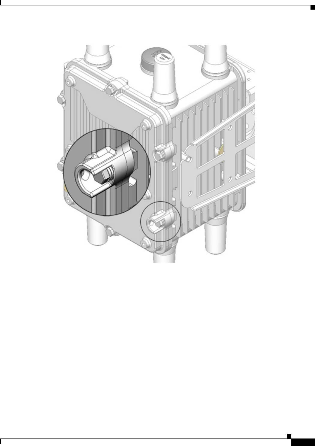
DEC. 2011—EFT REVIEW DRAFT—CISCO CONFIDENTIAL
4-7
Cisco 1240 Connected Grid Router Hardware Installation Guide
OL-26223-01
Chapter 4 Opening the Router Chassis
Door Features
Figure 4-6 Door Lock Block Detail

DEC. 2011—EFT REVIEW DRAFT—CISCO CONFIDENTIAL
4-8
Cisco 1240 Connected Grid Router Hardware Installation Guide
OL-26223-01
Chapter 4 Opening the Router Chassis
Door Features

CHAPTER
DEC. 2011—EFT REVIEW DRAFT—CISCO CONFIDENTIAL
4-1
Cisco 1240 Connected Grid Router Hardware Installation Guide
OL-12345-01
4
Mounting the Router
This chapter describes the safety information, equipment, and procedures required to mount the Cisco
1240 Connected Grid Router on a vertical pole or streetlight. This chapter contains these sections
• Overview of the Pole Mount Kits, page 4-1
• General Safety Information for Mounting, page 4-2
• Contents of the Mounting Kits, page 4-2
• Materials and Tools You Supply, page 4-6
• Mounting Instructions, page 4-6
• Grounding Instructions, page 4-18
Overview of the Pole Mount Kits
You will need some or all of the kits described in this section to install the router on a pole. Your
installation environment and requirements determine the kits you need.
The Contents of the Mounting Kits section includes a detailed description of each kit.
:
Cisco Part Number Name Description
CGR-PMK1000 Pole Mount Kit This kit is required for all pole or streetlight installations
and includes a mounting plate and the hardware required
to attach the mounting plate to a pole.
CGR-PMK-BAND Mounting
Bracket Kit
Use this kit if your installation requires a Cisco mounting
bracket to mount the router. This kit is used with the pole
kit and includes the hardware required to attach the
mounting bracket to the mounting plate.
CGR-PMK-BAND Band Strap Kit This kit includes two steel straps for mounting the router
on poles larger than 5 inches (14 cm) in diameter. This kit
is used together with the Pole Mount Kit. A Band-It Tool
is required to install the steel straps on a pole.
AIR-BAND-INST-TL= Strap Tool Kit This kit includes a Band-It tool that is required when using
steel straps to install the router on poles larger than
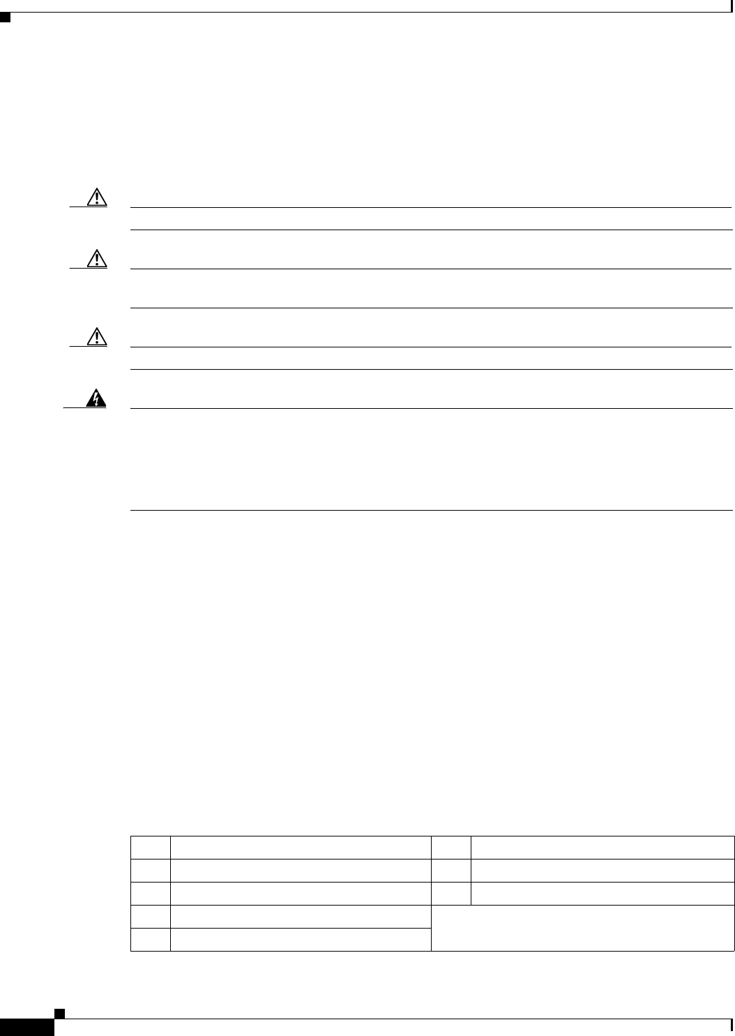
DEC. 2011—EFT REVIEW DRAFT—CISCO CONFIDENTIAL
4-2
Cisco 1240 Connected Grid Router Hardware Installation Guide
OL-12345-01
Chapter 4 Mounting the Router
General Safety Information for Mounting
General Safety Information for Mounting
Before performing any of the tasks in this chapter, read the safety warnings in this section and in the
Installation Safety and Site Preparation chapter.
One person is required to properly and safely mount the router.
Caution All mounting methods at any location are subject to the acceptance of local jurisdiction.
Caution The mounting surface, attaching screws, and optional wall anchors must be able to support a
50 pound (22.7 kg) static weight.
Caution Personnel mounting the router must understand grounding methods.
Warning
Do not locate the antenna near overhead power lines or other electric light or power circuits, or
where it can come into contact with such circuits. When installing the antenna, take extreme care
not to come into contact with such circuits, as they may cause serious injury or death. For proper
installation and grounding of the antenna, please refer to national and local codes (for example,
U.S.:NFPA 70, National Electrical Code, Article 810, Canada: Canadian Electrical Code, Section 54).
Statement 1052
Contents of the Mounting Kits
This section describes the contents of the mounting kits available for the router and when you should
use each kit.
Pole Mount Kit
When to Use
Use the Cisco pole mount kit to install the mounting plate on any pole or streetlight. The kit supports
poles that meet the following criteria:
• Size—2 to 16 inch diameter poles
• Material—Metal, wood, or fiberglass poles
Item Description Item Description
1Mounting plate (18.03 x 23.11 x 5.48 cm) 5M8 x 4.25 washer
2Clamp brackets (17.32 x 4.31 x 3.42 cm) 63/8-in. carriage bolt, 7 in. (10.2 cm) length
3M8 x 4.25 hex nut
4M8 x 4.25 split lock washer
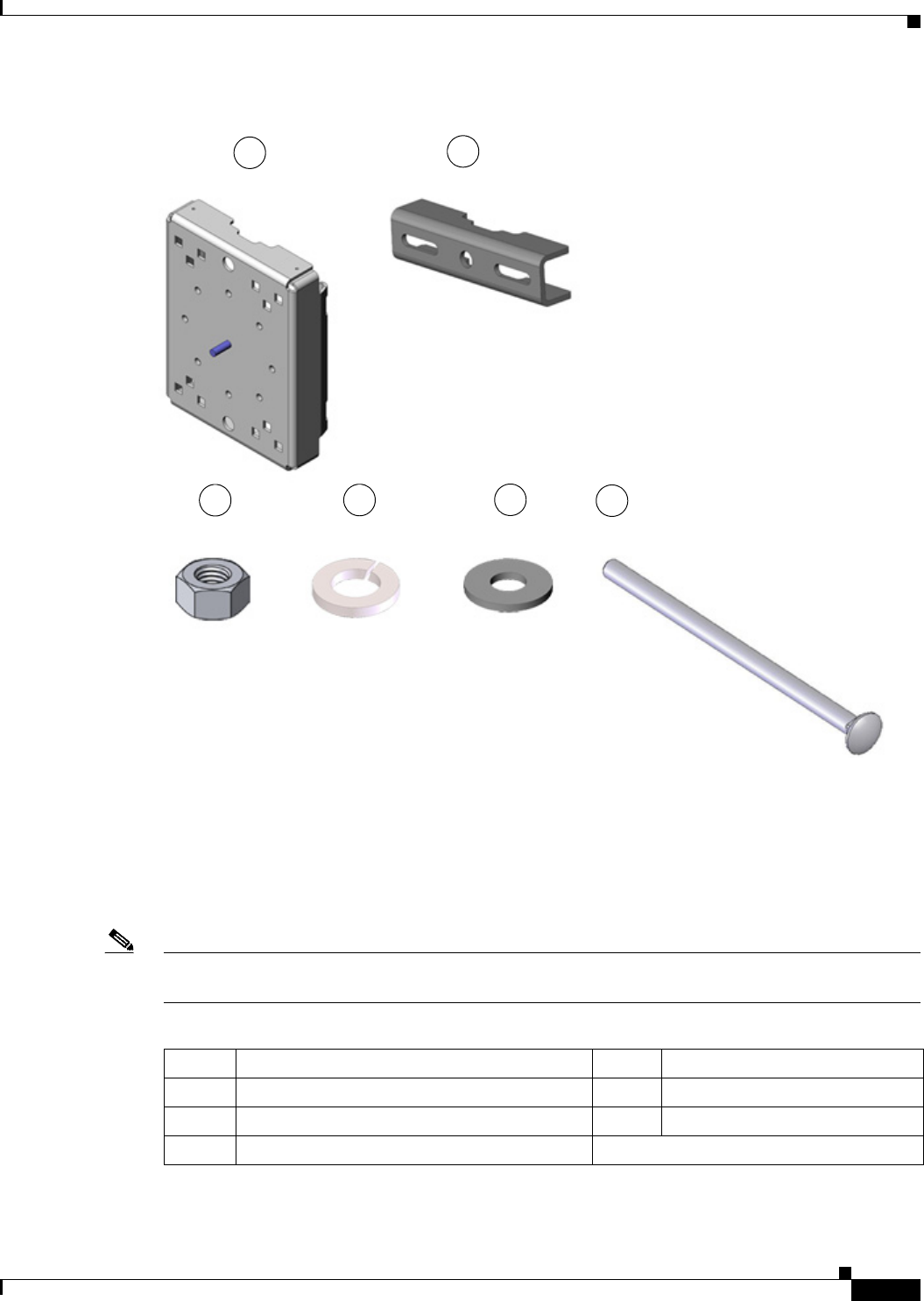
DEC. 2011—EFT REVIEW DRAFT—CISCO CONFIDENTIAL
4-3
Cisco 1240 Connected Grid Router Hardware Installation Guide
OL-12345-01
Chapter 4 Mounting the Router
Contents of the Mounting Kits
Figure 4-1 Pole Mount Kit Contents
Mounting Bracket Kit
When to Use
Use the Mounting Bracket Kit if you require a Cisco mounting bracket. The mounting bracket attaches
to the mounting plate, and then the router is installed on the mounting bracket.
Note You can optionally use any compatible mounting bracket with the Cisco Pole Mount Kit. Check with
your authorized Cisco reseller for compatible mounting brackets.
1
x1
2
x2
3
x4
4
x4
5
x4
6
x4
Item Description Item Description
1Mounting bracket (25.53 x 19.13 x 22.87 cm) 4Bolt (M8 x 1.25)
2Split lock washer (M8) 5Serrated nut (M8 x 1.25)
3Washer (M8)
DEC. 2011—EFT REVIEW DRAFT—CISCO CONFIDENTIAL
4-4
Cisco 1240 Connected Grid Router Hardware Installation Guide
OL-12345-01
Chapter 4 Mounting the Router
Contents of the Mounting Kits
Figure 4-2 Mounting Bracket Kit Contents
Band Strap Kit
When to Use
Use the straps in the Band Strap Kit when you mount the router on a pole larger than 5 inches (12.7 cm)
in diameter. This installation also requires the Pole Mount Kit and the Strap Tool Kit.
3
1
2 4 5
x4 x4 x4 x1
x1
Item Description
1Steel straps (2)
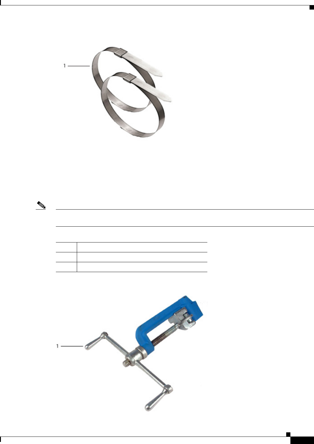
DEC. 2011—EFT REVIEW DRAFT—CISCO CONFIDENTIAL
4-5
Cisco 1240 Connected Grid Router Hardware Installation Guide
OL-12345-01
Chapter 4 Mounting the Router
Contents of the Mounting Kits
Figure 4-3 Band Strap Kit Contents
Strap Tool Kit
When to Use
Use the tool in the Strap Tool Kit to attach the steel straps included in the Band Strap Kit. Steel straps
are required to install the mounting plate on poles larger than 5 inches (12.7 cm) in diameter.
Note The tool in the Strap Tool Kit is manufactured and supported by BAND-IT. For more information about
the tool, see http://www.band-it-idex.com.
Figure 4-4 Strap Tool Kit Contents
Item Description
1Strap tool
2Strap tool documentation (not shown)

DEC. 2011—EFT REVIEW DRAFT—CISCO CONFIDENTIAL
4-6
Cisco 1240 Connected Grid Router Hardware Installation Guide
OL-12345-01
Chapter 4 Mounting the Router
Materials and Tools You Supply
Materials and Tools You Supply
You must supply some or all of these items to mount the router on a pole. The items you supply depends
on the installation procedure that you use.
Mounting Instructions
This section includes all the procedures required to mount the router on any supported pole type.
Router Orientation
When mounting the router on a pole, ensure that:
• The router is oriented with the chassis cabling openings pointing down so the router cables can be
correctly connected through the openings and so the router door opens correctly, as shown in
Figure 4-13.
• The router is mounted with the hinged access cover facing out.
Install the Mounting Plate on a Pole
This section describes three different procedures for installing the mounting plate on a pole. Follow the
instructions for the pole type used in your installation.
The instructions in these section refer to the mounting plate features shown in Figure 4-5.
• Install the Mounting Plate—Poles Up to 5 Inches in Diameter
• Install the Mounting Plate—Poles Larger than 5 Inches in Diameter
• Install the Mounting Plate—Through-Pole Mounting (Optional)
Item Required for These Procedures
13-mm box-end wrench or socket set • Install the Mounting Plate—Poles Up to 5 Inches in Diameter
• Install the Mounting Plate—Through-Pole Mounting (Optional)
• Attach the Mounting Bracket to the mounting plate or extension
bracket
Bolt, standard washer, fender washer, and nut,
5/8 in. (2 sets)—Bolt length depends on the size of
the pole used in the installation.
Install the Mounting Plate—Through-Pole Mounting (Optional)
Drill and drill bit Install the Mounting Plate—Through-Pole Mounting (Optional)
Phillips screwdriver, or other screwdriver for
cross-recessed screws
Ground the Router
Crimping tool or pliers Ground the Router
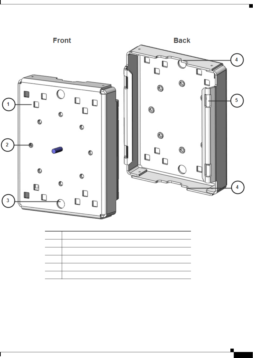
DEC. 2011—EFT REVIEW DRAFT—CISCO CONFIDENTIAL
4-7
Cisco 1240 Connected Grid Router Hardware Installation Guide
OL-12345-01
Chapter 4 Mounting the Router
Mounting Instructions
Figure 4-5 Mounting Plate Features — Front and Back View
Install the Mounting Plate—Poles Up to 5 Inches in Diameter
To install the mounting plate on a vertical pole up to 5 inches (12.7 cm) in diameter, follow these steps
and refer to Figure 4-6 and Figure 4-7.
Item Description
1Carriage bolt holes (4)
2Bracket mount holes (8)
3Clearance holes, 3/4 in. (2)
4Pole clamp notches (2)
5Steel band strap slots (4)
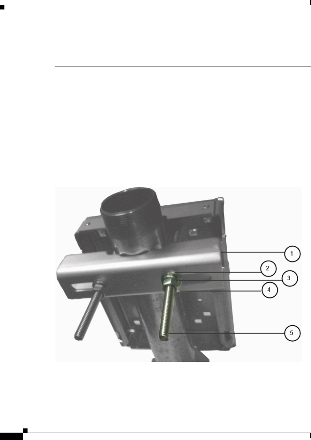
DEC. 2011—EFT REVIEW DRAFT—CISCO CONFIDENTIAL
4-8
Cisco 1240 Connected Grid Router Hardware Installation Guide
OL-12345-01
Chapter 4 Mounting the Router
Mounting Instructions
What You Need
• Mounting plate, carriage bolts, and clamp brackets included in the Pole Mount Kit.
• Socket wrench that you provide.
Step 1 Select a mounting location on the pole and place the top and bottom pole clamp bracket (1) notches
against the pole.
Step 2 Place one of the clamp brackets (1) on the opposite side of the pole, aligning the clamp bracket holes
with the top two carriage bolt holes on the mounting plate.
Step 3 Insert a carriage bolt (5) through each of the top two carriage bolt holes on the mounting plate and
through the holes in the clamp brackets.
Step 4 Position the each bolt in the clamp so that the bolt is next to the pole, as shown in Figure 4-6.
Step 5 Follow these steps to place the bracket hardware on each carriage bolt, as shown in Figure 4-6:
a. Place the washer (2) and then the split lock washer (3) on the back of each carriage bolt (5).
b. Thread the hex nut (4) on each carriage bolt. The split lock washer should be between the washer
and the nut.
Figure 4-6 Carriage Bolt Hardware Detail
Step 6 Hand tighten the hex nuts (do not overtighten).
Step 7 Repeat Step 3 through Step 6, installing the two bottom carriage bolts and the second clamp bracket at
the bottom of the mounting plate.
Step 8 Position the mounting plate and clamp brackets on the pole as needed before further tightening the
carriage bolts.
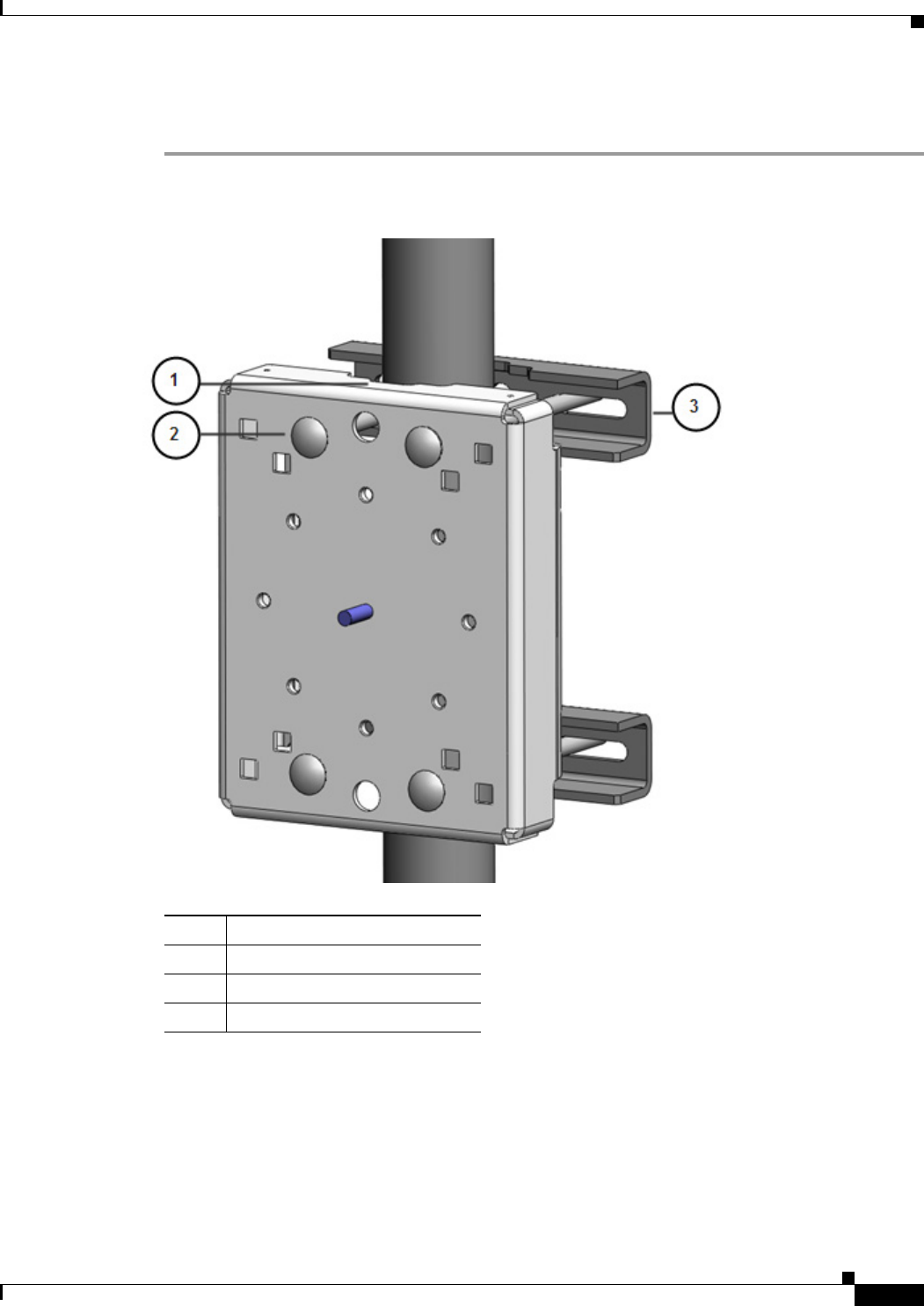
DEC. 2011—EFT REVIEW DRAFT—CISCO CONFIDENTIAL
4-9
Cisco 1240 Connected Grid Router Hardware Installation Guide
OL-12345-01
Chapter 4 Mounting the Router
Mounting Instructions
Step 9 Use a socket wrench to evenly tighten all four carriage bolts to finish installing the mounting plate on
the pole.
Figure 4-7 Mounting Plate Installed on Pole with Clamp Brackets
Install the Mounting Plate—Poles Larger than 5 Inches in Diameter
To install the mounting plate on a vertical pole that is larger than 5 inches (12.7 cm) in diameter, follow
these steps and refer to Figure 4-8.
Item Description
1Pole clamp notch
2Carriage bolts (4)
3Pole clamps (2)
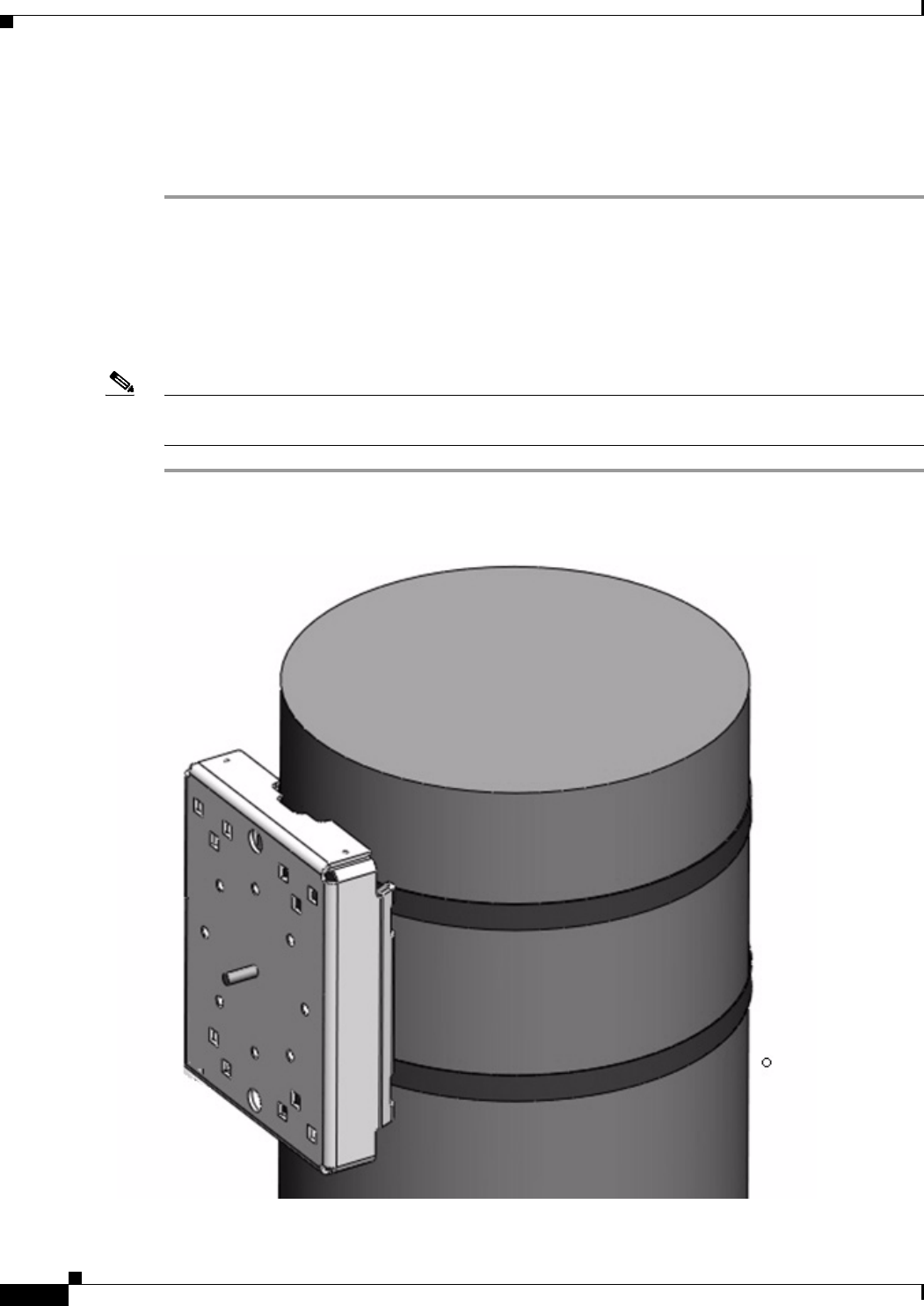
DEC. 2011—EFT REVIEW DRAFT—CISCO CONFIDENTIAL
4-10
Cisco 1240 Connected Grid Router Hardware Installation Guide
OL-12345-01
Chapter 4 Mounting the Router
Mounting Instructions
What you need
• Mounting plate and steel straps included in the Pole Mount Kit.
• Band-It tool included in the Strap Tool Kit
Step 1 Assemble the straps and the mounting plate by threading the two steel straps through the band strap slots
on the mounting plate.
Step 2 Select a mounting location on the pole.
Step 3 Position the mounting plate on the pole as needed and tighten the straps around the pole.
Step 4 Use the Band-It strap tool to tighten the metal bands around the pole, following the instructions in the
box with the tool. Ensure the metal bands are as tight as possible.
Note When the metal bands are tightened to the full tension, the mounting plate cannot be adjusted unless the
metal bands are disassembled or cut.
Figure 4-8 Mounting Plate Installed on Pole with Steel Straps

DEC. 2011—EFT REVIEW DRAFT—CISCO CONFIDENTIAL
4-11
Cisco 1240 Connected Grid Router Hardware Installation Guide
OL-12345-01
Chapter 4 Mounting the Router
Mounting Instructions
Install the Mounting Plate—Through-Pole Mounting (Optional)
If the pole used in your installation is made of wood, you can optionally install the mounting plate using
the procedure described in this section. This is an alternate mounting method to the following two
mounting methods, which can also be used when mounting the router on a wood pole:
• Install the Mounting Plate—Poles Up to 5 Inches in Diameter
• Install the Mounting Plate—Poles Larger than 5 Inches in Diameter
What You Need
• Mounting plate included in the Pole Mount Kit.
• Hardware that you supply: 5/8-in. through bolt (length depends on the pole size in your installation),
standard washer, fender washer, nut (2 sets)
• Tools that you supply: Drill, drill bit (for 5/8-in. through bolts), and socket wrench.
Step 1 Place the mounting plate on the selected mounting location on the pole.
Step 2 Mark the drilling locations on the pole through the clearance holes and remove the mounting plate.
Step 3 Drill holes completely through the pole at the points you marked in Step 2.
Step 4 Position the mounting plate over the drilled holes. Align the clearance holes on the mounting plate with
the drilled holes.
Step 5 Place a standard washer against one of the clearance holes on the mounting plate, then feed the bolt
through the washer, clearance hole, and drilled hole. Push the bolt all the way through the pole. See
Figure 4-9.
Step 6 Follow these steps on the opposite side of the pole:
a. Place a fender washer on the end of the bolt, and then a nut.
b. Hand tighten the nut.
Step 7 Repeat Step 5 and Step 6 for the second bolt.
Step 8 Use a socket wrench to evenly tighten both bolts to finish installing the mounting plate on the wooden
pole.
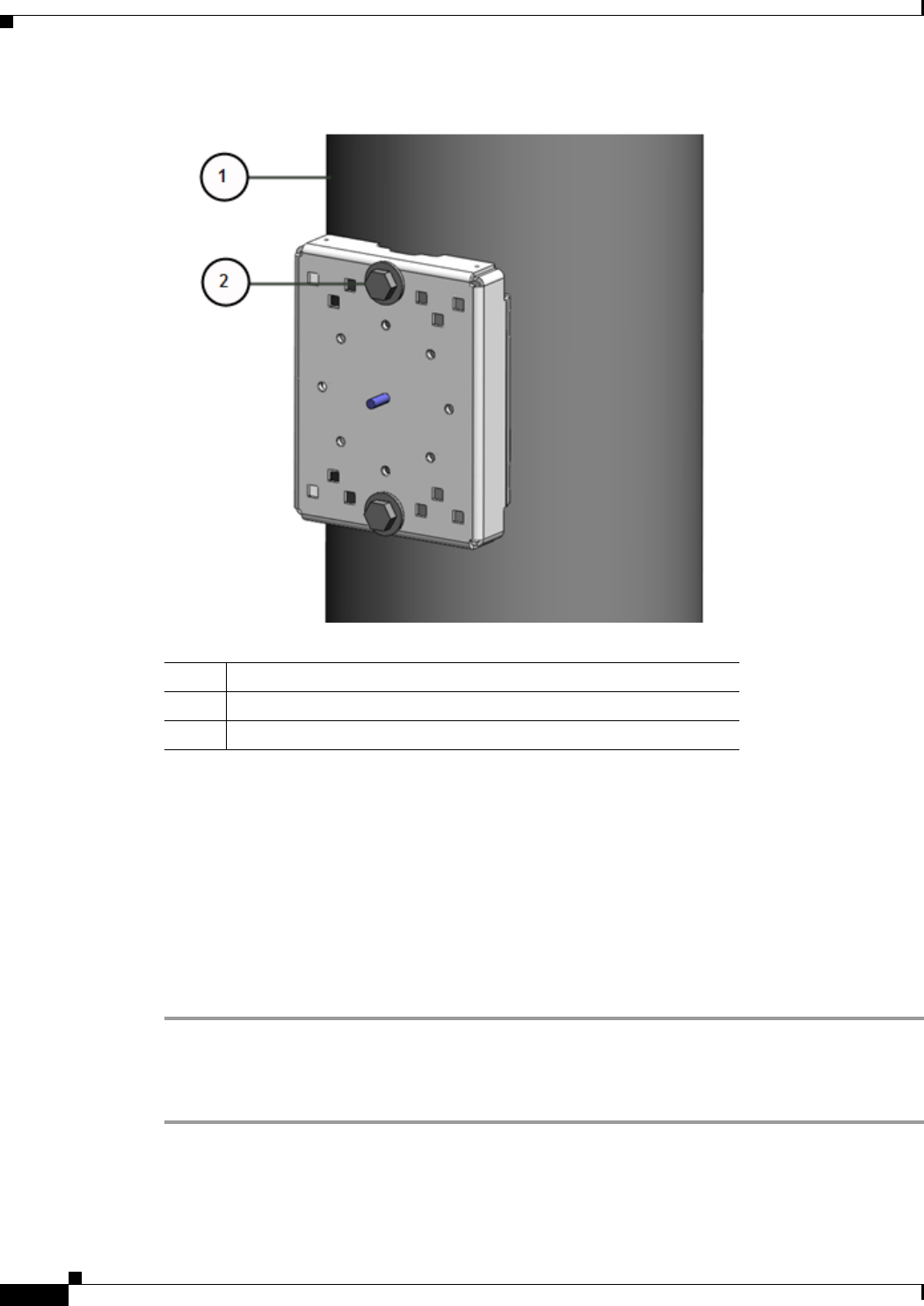
DEC. 2011—EFT REVIEW DRAFT—CISCO CONFIDENTIAL
4-12
Cisco 1240 Connected Grid Router Hardware Installation Guide
OL-12345-01
Chapter 4 Mounting the Router
Mounting Instructions
Figure 4-9 Mounting Plate Installed on Wooden Pole with Through Bolts
Attach the Mounting Bracket
This section describes how to attach the mounting bracket to the mounting plate.
Assemble Bracket Hardware
Several of the procedures in this section require you to assemble the bracket hardware before installing
the bracket. A bracket hardware set consists of one bolt, one washer, one split lock washer, and one nut.
Take these steps to assemble the hardware:
Step 1 Slide the split lock washer (2) on the bolt (1).
Step 2 Slide the regular washer (3) on the bolt (1).
The split lock washer should be between the regular washer and the bolt as shown in Figure 4-10.
Item Description
1Wood pole
25/8-in. through bolts (2)
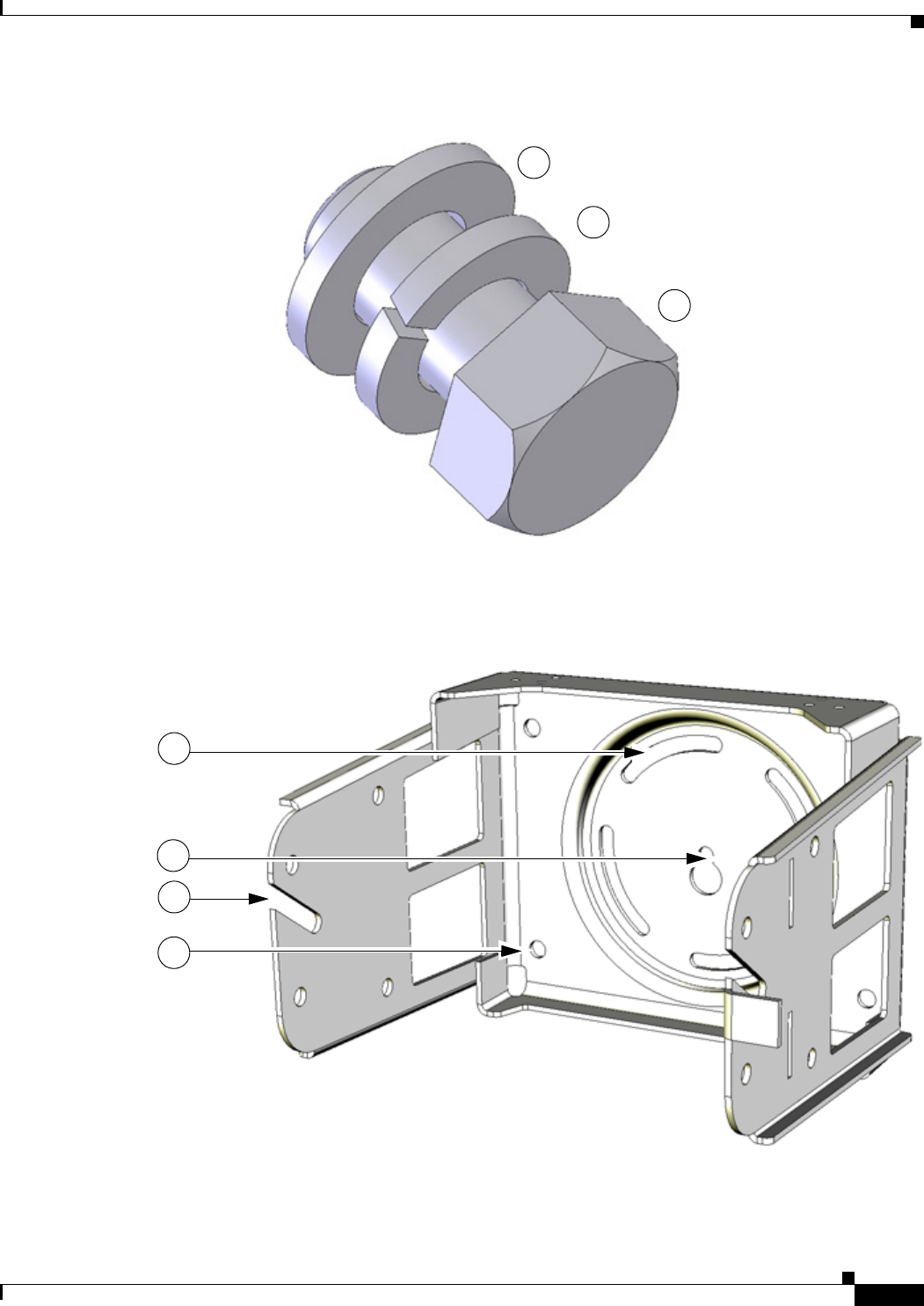
DEC. 2011—EFT REVIEW DRAFT—CISCO CONFIDENTIAL
4-13
Cisco 1240 Connected Grid Router Hardware Installation Guide
OL-12345-01
Chapter 4 Mounting the Router
Mounting Instructions
Figure 4-10 Assemble Bracket Hardware Sets
The instructions for the procedures in this section refer to the mounting plate features shown in
Figure 4-11.
Figure 4-11 Mounting Bracket Features
3
1
2
3
1
2
4

DEC. 2011—EFT REVIEW DRAFT—CISCO CONFIDENTIAL
4-14
Cisco 1240 Connected Grid Router Hardware Installation Guide
OL-12345-01
Chapter 4 Mounting the Router
Mounting Instructions
To attach the mounting bracket to the mounting plate, follow these steps and refer to Figure 4-12. The
mounting plate must be installed according to the instructions in the Install the Mounting Plate on a Pole
section.
What You Need
• Mounting bracket and hardware included in the Mounting Bracket Kit.
• Socket wrench that you supply.
Step 1 Assemble four sets of bracket hardware (washer, split lock washer, and bolt) as shown in the section
Assemble Bracket Hardware, page 4-12.
Step 2 Place the mounting bracket (3) against the mounting plate (1) by inserting the bracket quick hang notch
over the mounting plate quick hang stud (6).
Step 3 Align the pivot grooves (4) on the bracket with four of the bracket mount holes (2) on the mounting plate.
Follow these guidelines:
• Each of the four pivot grooves on the bracket must be attached to at least one bracket mount hole on
the mounting plate.
• The final desired orientation of the mounting plate and router determine which bracket mount holes
are used.
• Mount the router according to the instructions in the Router Orientation section.
Step 4 Thread the serrated nut onto the quick mount stud (6) and hand tighten (do not overtighten).
Step 5 Insert one bolt assembly (5) through one of the pivot grooves (4) on the bracket and then through the
corresponding bracket mount hole on the mounting plate.
Step 6 Repeat Step 5 for the remaining bolt assemblies.
Step 7 Position the mounting bracket on the mounting plate as needed before further tightening the bolts.
Step 8 Use a socket wrench to evenly tighten all four bolts and the serrated nut to finish installing the bracket
on the plate.
Item Description
1Pivot grooves (4)
2Quick hang notch
3Quick hang slots (2)
4Wall mount holes (4)
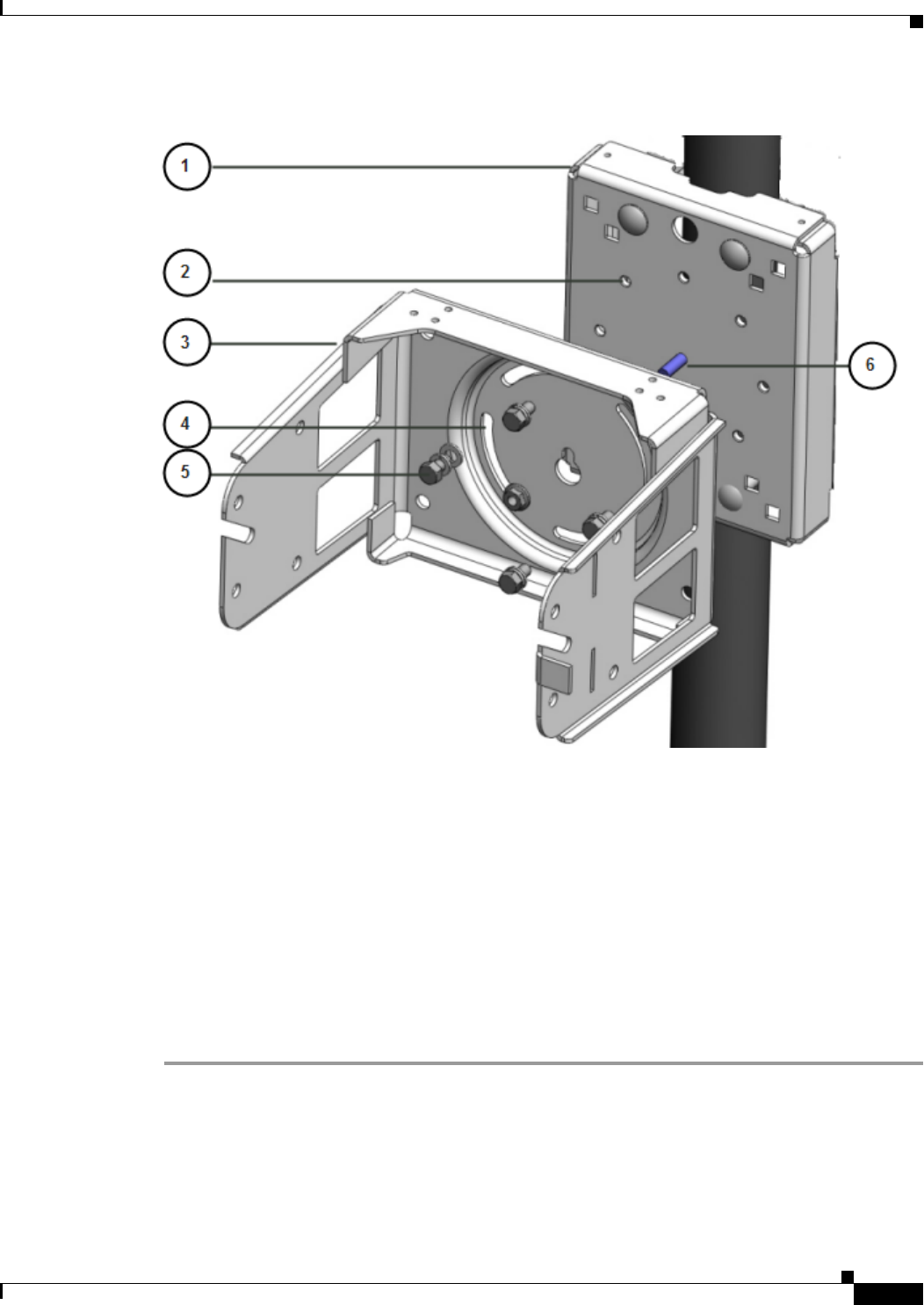
DEC. 2011—EFT REVIEW DRAFT—CISCO CONFIDENTIAL
4-15
Cisco 1240 Connected Grid Router Hardware Installation Guide
OL-12345-01
Chapter 4 Mounting the Router
Mounting Instructions
Figure 4-12 Mounting Bracket Attached to Mounting Plate
Install the Router on the Mounting Bracket
This section describes how to attach the router to the mounting bracket. The instructions for the
procedures in this section refer to the mounting bracket kit contents shown in Figure 4-2 and the bracket
features described in Figure 4-11.
What You Need
• Mounting bracket and hardware included in the Mounting Bracket Kit.
• Socket wrench that you supply.
To mount the router on the bracket, take these steps and refer to Figure 4-13 and Figure 4-14:
Step 1 Assemble eight sets of bracket hardware (washer, split lock washer, and bolt) as shown in the section
Assemble Bracket Hardware, page 4-12.
Step 2 One each side of the router, attach one set of hinge bolt hardware to the mounting bracket connector (1).
Do not tighten the hardware until Step 5. There must be enough space between the washer and the router
to slide the router onto the bracket.
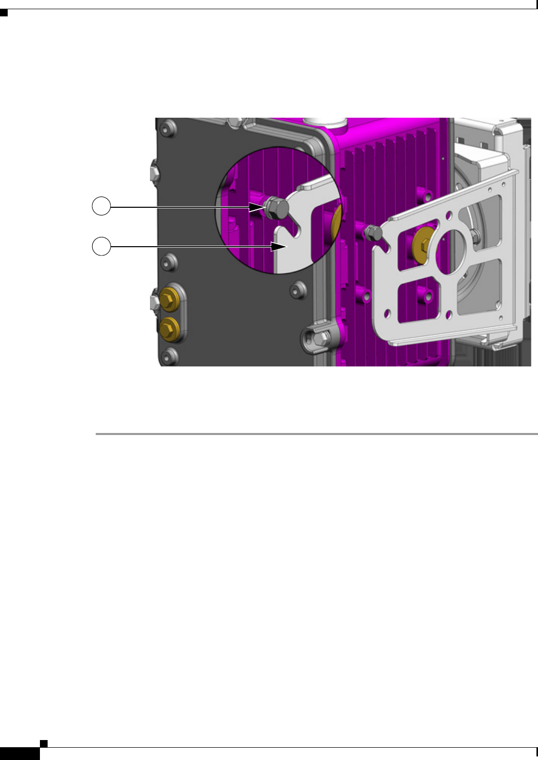
DEC. 2011—EFT REVIEW DRAFT—CISCO CONFIDENTIAL
4-16
Cisco 1240 Connected Grid Router Hardware Installation Guide
OL-12345-01
Chapter 4 Mounting the Router
Mounting Instructions
Step 3 Slide the router onto the bracket by inserting the hinge bolts you attached in Step 2 into the bracket quick
hang slots (2).
Figure 4-13 Attach Hinge Bolt to Both Sides of Router
Step 4 Attach the three remaining sets of hardware to each side of the bracket and router, as shown in
Figure 4-14.
Step 5 Use a socket wrench to evenly tighten all four bolts.
1
2
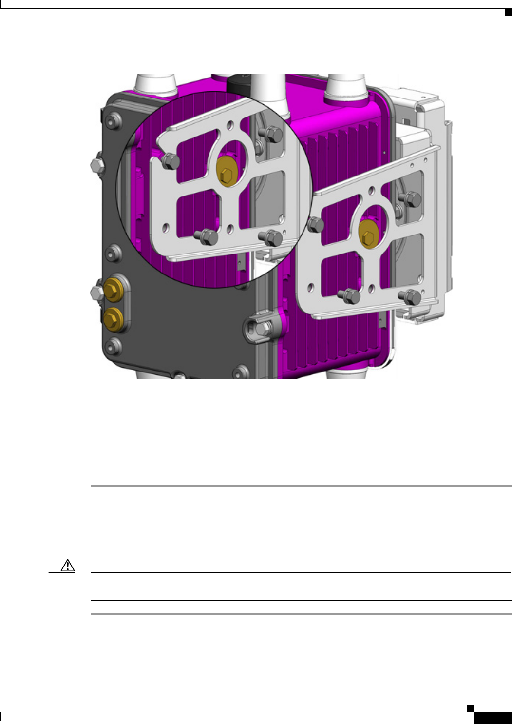
DEC. 2011—EFT REVIEW DRAFT—CISCO CONFIDENTIAL
4-17
Cisco 1240 Connected Grid Router Hardware Installation Guide
OL-12345-01
Chapter 4 Mounting the Router
Mounting Instructions
Figure 4-14 Attach Remaining Bolts to Bracket and Router
SD Card Slot Access for Bracket-Mounted Routers
When the Cisco mounting bracket is attached the router according to the instructions in this chapter, the
bracket blocks access to the SD card port slot the router exterior.
To access the SD card slot (1) without removing the router from the bracket or any mounting installation
that uses the bracket, take these steps and refer to Figure 4-15:
Step 1 One one side of the router, remove the three bolts shown in Figure 4-14.
Step 2 Loosen but do not remove the fourth bolt that is inserted in the quick hang slot.
Step 3 Repeat Step 1 through Step 2 on the other side of the router.
Step 4 Tilt the bracket on the quick mount slot, as shown in Figure 4-15.
Caution Be sure to reinstall and tighten all eight bolts when you finish using the SD card slot. The router must
be securely attached to the mounting bracket with four bolts on each side.
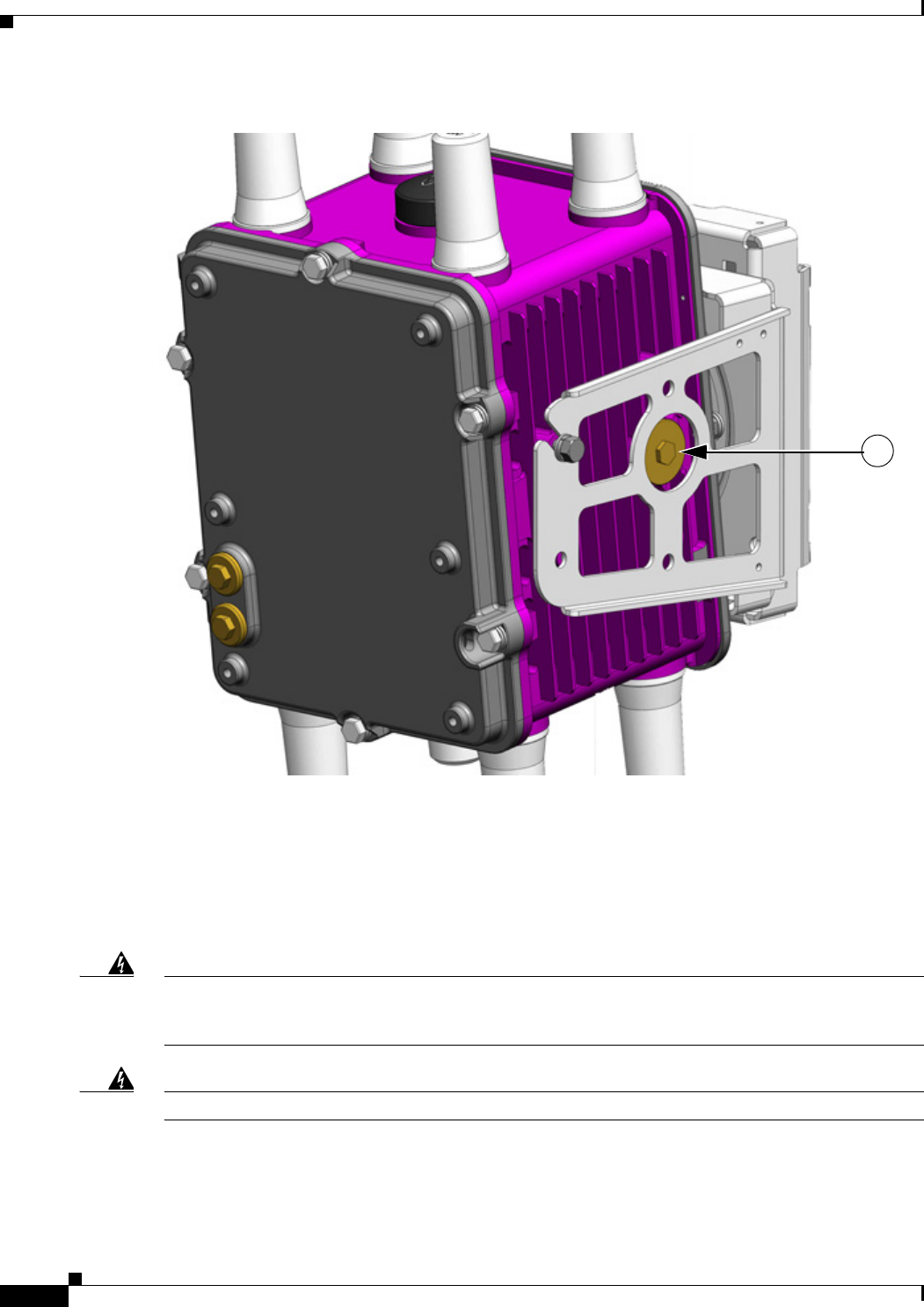
DEC. 2011—EFT REVIEW DRAFT—CISCO CONFIDENTIAL
4-18
Cisco 1240 Connected Grid Router Hardware Installation Guide
OL-12345-01
Chapter 4 Mounting the Router
Grounding Instructions
Figure 4-15 Tilt Mounting Bracket for SD Card Slot Access
Grounding Instructions
In all installations, after the router is mounted, you must properly ground the unit according to the
instructions in this section before connecting network and power cables as described in Installing the
Router, page 6-1.
Warning
Warning This equipment must be externally grounded using a customer-supplied ground wire before
power is applied. Contact the appropriate electrical inspection authority or an electrician if you are
uncertain that suitable grounding is available.
Statement 366
Warning
Installation of the equipment must comply with local and national electrical codes.
Statement 1074
1
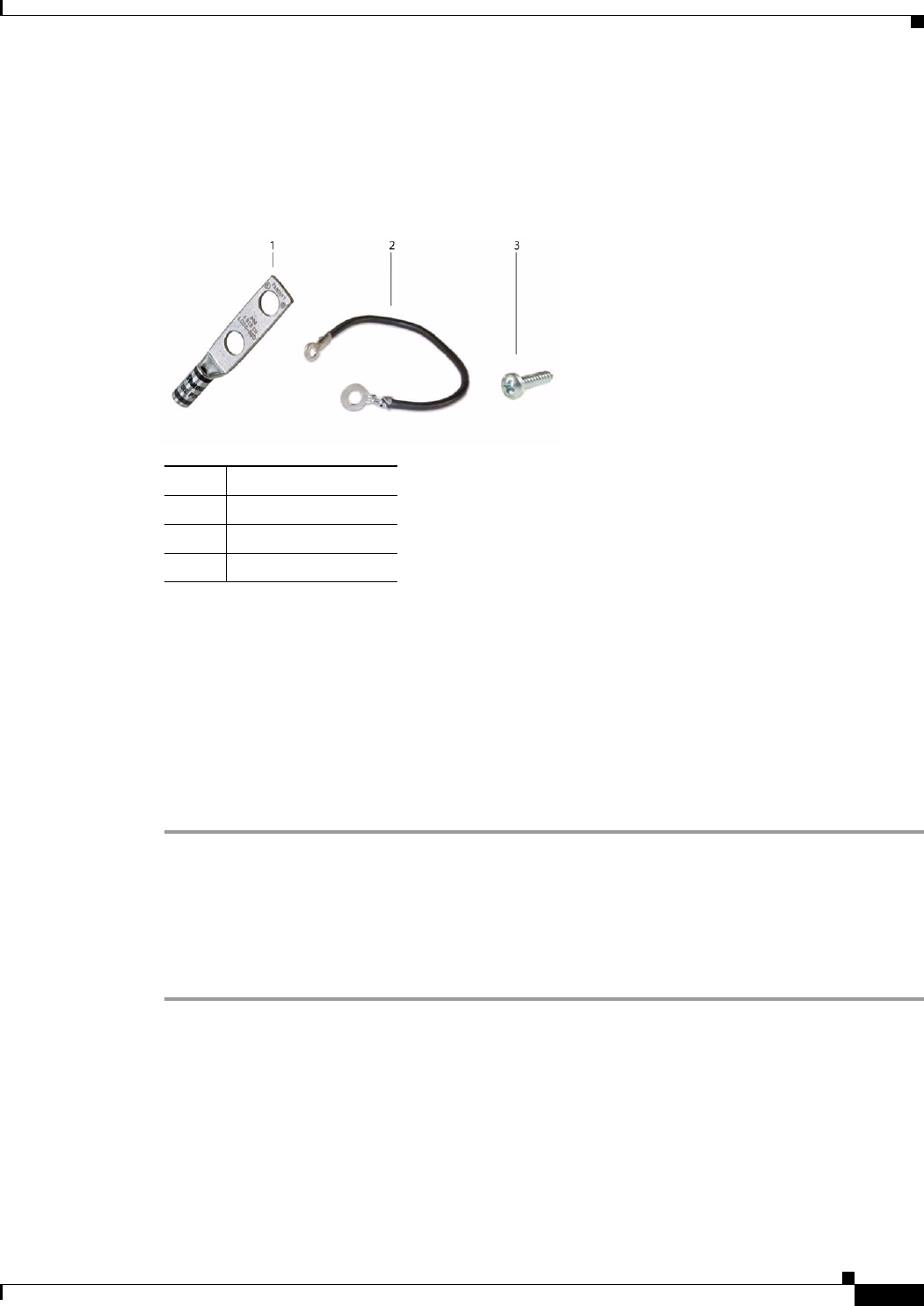
DEC. 2011—EFT REVIEW DRAFT—CISCO CONFIDENTIAL
4-19
Cisco 1240 Connected Grid Router Hardware Installation Guide
OL-12345-01
Chapter 4 Mounting the Router
Ground the Router
Grounding Hardware
The router is shipped with a grounding kit, shown in Figure 4-16.
Figure 4-16 Router Grounding Kit Contents
Materials You Supply
You must provide the tools listed in Materials and Tools You Supply, page 4-6.
Ground the Router
Take the following steps to ground the router:
Step 1 Use the appropriate crimping tool or pliers to crimp the 6-gauge ground wire (included in the grounding
kit) to the grounding lug.
Step 2 Connect the grounding lug to the access point grounding connectors shown in Figure 4-17 using the
supplied grounding screws. Tighten the grounding screws to 7 to 8 15 lbf-in. Do not overtighten!
Step 3 If necessary, strip the other end of the ground wire and connect it to a reliable earth ground, such as a
grounding rod or an appropriate grounding point on a pole that is grounded.
Item Description
1Grounding lug
26-gauge ground wire
3Screws (2)
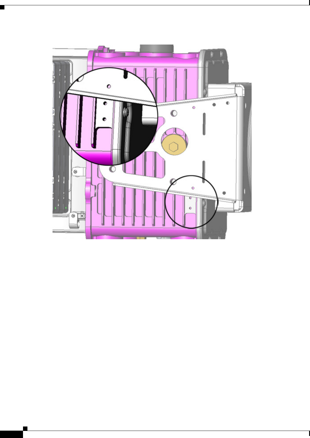
DEC. 2011—EFT REVIEW DRAFT—CISCO CONFIDENTIAL
4-20
Cisco 1240 Connected Grid Router Hardware Installation Guide
OL-12345-01
Chapter 4 Mounting the Router
Ground the Router
Figure 4-17 Grounding Lug Connectors

CHAPTER
DEC. 2011—EFT REVIEW DRAFT—CISCO CONFIDENTIAL
6-1
Cisco 1240 Connected Grid Router Hardware Installation Guide
OL-26223-01
6
Installing the Router
This chapter describes how to install the Cisco 1240 Connected Grid Router and includes the procedures
for basic router installation and for optional installation steps. The procedures you follow depend on
your network environment and requirements. This chapter contains the following sections:
• Before Installing, page 6-1
• Related Information, page 6-2
• Basic Hardware Installation, page 6-2
• Additional Router Connections, page 6-10
• Installing Modules and Antennas, page 6-24
Before Installing
Read this section and the Installation Safety and Site Preparation chapter before following any
installation procedures in this chapter.
Prepare the Installation Site
The procedures in this chapter assume that you have prepared the installation site according to the
information in the Installation Safety and Site Preparation chapter.
Read the Safety Information
Before performing any of the tasks in this chapter, read the safety warnings in this section and in the
Installation Safety and Site Preparation chapter.
Preventing Electrostatic Discharge Damage
Many of the components discussed in this chapter are sensitive to electrostatic discharge (ESD) damage,
which can occur when electronic cards or components are handled improperly, results in complete or
intermittent failures.

DEC. 2011—EFT REVIEW DRAFT—CISCO CONFIDENTIAL
6-2
Cisco 1240 Connected Grid Router Hardware Installation Guide
OL-26223-01
Chapter 6 Installing the Router
Related Information
To prevent ESD damage, follow these guidelines:
• Always use an ESD wrist or ankle strap and ensure that it makes good skin contact.
• Connect the equipment end of the strap to an unfinished chassis surface.
• Place a removed the memory card on an antistatic surface or in a static shielding bag. If the card will
be returned to the factory, immediately place it in a static shielding bag.
• Avoid contact between the card and clothing. The wrist strap protects the card from ESD voltages
on the body only; ESD voltages on clothing can still cause damage.
• Do not remove the wrist strap until the installation is complete.
Cabling Guidelines
Follow these guidelines for using cables with the router:
• Position cables so that they do not place strain on the router connectors.
• Organize cables into bundles when necessary to avoid intertwining.
• Inspect cables to ensure adequate routing and bend radius.
• Install cable ties that comply with your site requirements.
Related Information
This chapter describes installation procedures. For detailed, technical information about the router
hardware, including connector and cable descriptions, specifications, and pinouts, see the following
chapters:
• The Router Hardware Description chapter describes all aspects of the router hardware, including
internal and external features and connectors.
• The Connector and Cable Specifications appendix lists pinouts for the router connectors and cables.
Basic Hardware Installation
This section describes basis router installation steps. This is the minimum configuration required for the
router to power up and begin operating on the backhaul network.
The steps in this section require that AC power and Ethernet network connections are available at the
installation location, as described in the following Installation Safety and Site Preparation sections:
• Power Guidelines and Requirements, page 3-4
• Preparing for Network Connections, page 3-5
Connect to the Ethernet Backhaul Network
The available Ethernet connection must meet the requirements described in the Installation Safety and
Site Preparation chapter.
Step 1 Remove the cover from the external Ethernet connector.
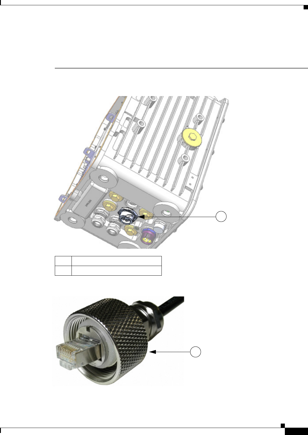
DEC. 2011—EFT REVIEW DRAFT—CISCO CONFIDENTIAL
6-3
Cisco 1240 Connected Grid Router Hardware Installation Guide
OL-26223-01
Chapter 6 Installing the Router
Basic Hardware Installation
Step 2 Connect local Ethernet cable to the router exterior Ethernet connector on the base of the router
(Figure 6-1).
Step 3 Tighten the cable coupling ring (Figure 6-2) over the exterior router Ethernet connector to ensure an
adequate seal over the connector.
Figure 6-1 External Ethernet Connector
Figure 6-2 Ethernet Cable with Coupling Ring
Item Description
1External Ethernet connector
1
1
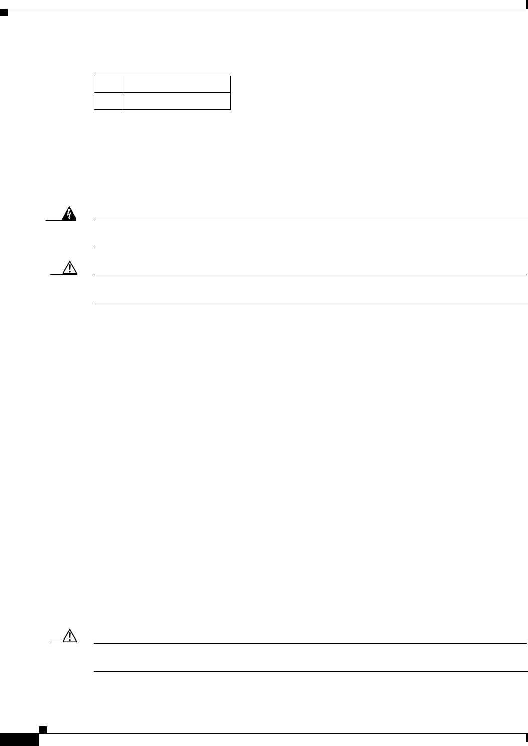
DEC. 2011—EFT REVIEW DRAFT—CISCO CONFIDENTIAL
6-4
Cisco 1240 Connected Grid Router Hardware Installation Guide
OL-26223-01
Chapter 6 Installing the Router
Basic Hardware Installation
Connecting to AC Power
When connecting the router to AC power, you must ensure that the following conditions are met:
• AC power can be readily and conveniently removed from the router. The power should not be
removed by disconnecting the AC power connector on the unit.
Warning
The plug-socket combination must be accessible at all times, because it serves as the main
disconnecting device.
Statement 1019
Caution Before connecting or disconnecting the power cord, you must remove AC power from the power cord
using a suitable service disconnect.
• You must protect AC power plugs and AC receptacles from water and other outdoor elements. You
can use a UL-listed waterproofing enclosure suitable for covering the AC receptacle and AC power
plug that supplies power to the unit, as described in Article 406 of the National Electric Code
(NEC).
• When you install the unit outdoors, or in a wet or damp location, the AC branch circuit that powers
the unit should have ground fault protection (GFCI), as required by Article 210 of the NEC.
• If the power cord goes through a metal cover, a bushing should be installed to prevent fraying of the
cord. When using a strain relief bushing, you should follow these recommendations:
–
Use properly sized parts
–
Use bushings that are safety certified
–
Use parts that are suitable for outdoor installation
• Ensure that the user-supplied AC power plug is certified for outdoor use and has a minimum IP67
rating, such as Interpower 84131251 or Hubbell HBL316P6W (IEC/EN60309 pin-and-sleeve type
connectors).
AC Power Cable
The router supports the Cisco AC power cable that is shipped with the unit. One end of the cable has the
router AC power connector; the other end is unfinished and you must provide and attach an AC power
plug. The AC power plug you use depends on the power source, such as a junction box, to which you
will attach the cable.
You might have to cut the cable if a specific cable length is needed for your installation.
Caution Ensure that the power source is OFF before connecting or disconnecting the power cord wires from the
power source.
Item Description
1Coupling ring
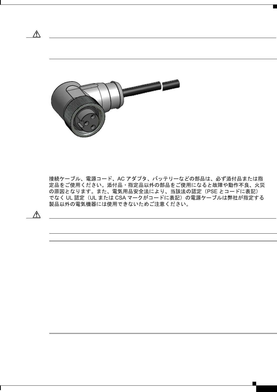
DEC. 2011—EFT REVIEW DRAFT—CISCO CONFIDENTIAL
6-5
Cisco 1240 Connected Grid Router Hardware Installation Guide
OL-26223-01
Chapter 6 Installing the Router
Basic Hardware Installation
Caution To attach the appropriate connector the AC power cable, follow the manual or other instructions
provided by the electrical equipment vendor, ensuring that you comply with the electrical codes for your
installation location.
Figure 6-3 Router AC Power Cable (Router Connector End)
Connect to AC Power
Follow these steps to connect the router AC connector (Figure 6-4) to an AC power source.
Caution When connecting the router AC power connector, always connect the router end of the cable first. When
removing the AC power connector, always disconnect the router end of the cable last.
Step 1 Verify that the unit is grounded as described in the chapter Mounting the Router.
Step 2 Verify that the SD flash memory module is installed correctly as described in the chapter Using the SD
Flash Memory Module.
Step 3 Turn off power to the AC power source at the designated circuits.
Step 4 Align the notch in the AC power cable connector (Figure 6-5) with the key in the router AC power
connector, then push the cable connector into the router connector. When the cable connector is fully
seated, rotate the cable connector ring clockwise until hand-tight.
Step 5 Confirm the router antennas are connected to the router before you apply power to the router.
Step 6 Connect the other end of the AC power cable to the power source, using the instructions that came with
the connecting device.
Step 7 Turn on AC power at the designated circuits. The router will power on and boot the software image.
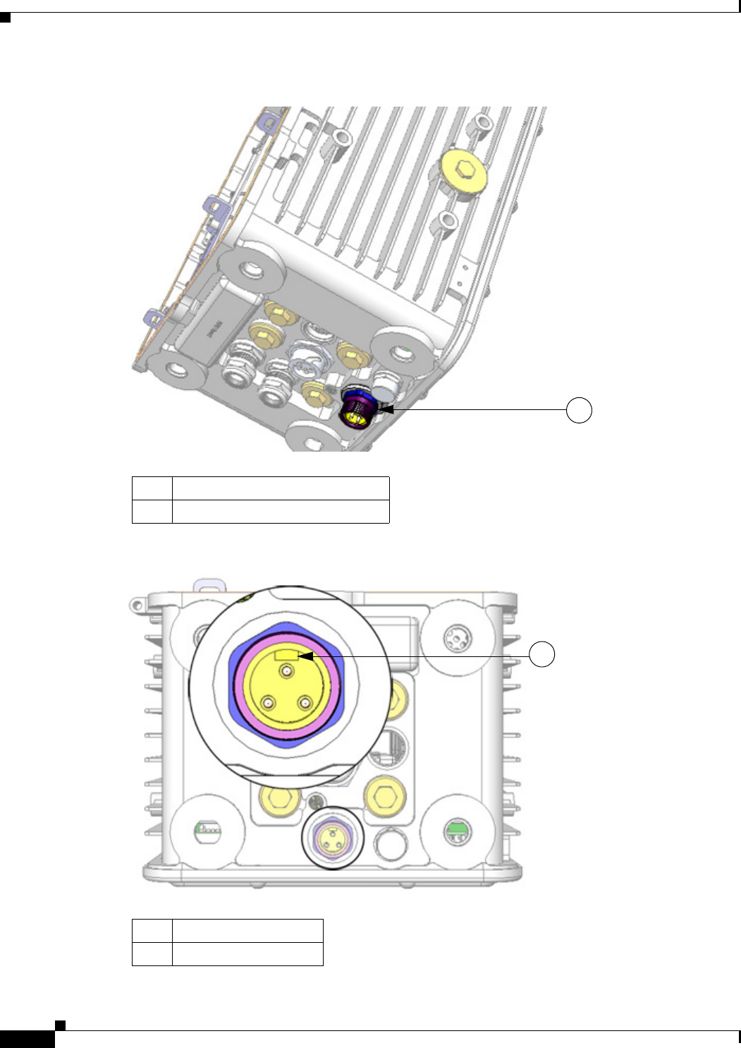
DEC. 2011—EFT REVIEW DRAFT—CISCO CONFIDENTIAL
6-6
Cisco 1240 Connected Grid Router Hardware Installation Guide
OL-26223-01
Chapter 6 Installing the Router
Basic Hardware Installation
Figure 6-4 Router AC Connector
Figure 6-5 AC Connector Notch
Item Description
1AC power connector
1
Item Description
1AC connector notch
1
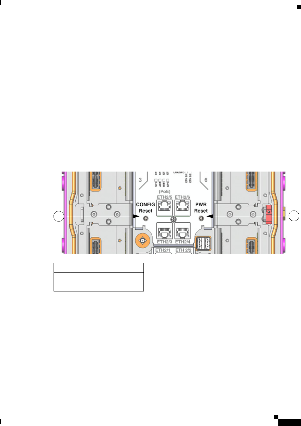
DEC. 2011—EFT REVIEW DRAFT—CISCO CONFIDENTIAL
6-7
Cisco 1240 Connected Grid Router Hardware Installation Guide
OL-26223-01
Chapter 6 Installing the Router
Basic Hardware Installation
Power and Reset Buttons
There are two reset buttons inside the router chassis (Figure 6-6):
• POWER Reset—Pressing the Power button power cycles the router hardware without powering
down the router. The router continues to operate during this process.
• CONFIG Reset—Pressing the Reset button restores the router software configuration the factory
default and power cycles the router hardware.
Accessing the Buttons
You must provide a pin, paper clip, or other thin metal tool to access and press these buttons.
Related Information
For detailed instructions for opening chassis door, see the chapter Opening the Router Chassis.
Figure 6-6 Router Power and Reset Buttons
Item Description
1CONFIG Reset button
2PWR Reset button
12
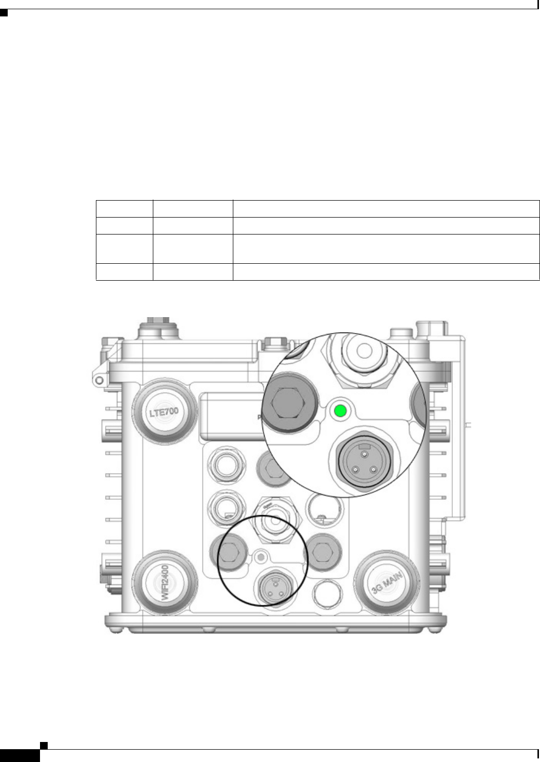
DEC. 2011—EFT REVIEW DRAFT—CISCO CONFIDENTIAL
6-8
Cisco 1240 Connected Grid Router Hardware Installation Guide
OL-26223-01
Chapter 6 Installing the Router
Basic Hardware Installation
Verify the Router Basic Installation
After you connect the router to the network and power on the router, verify that the installation was
successful by performing the checks described in this section.
Check the System (SYS) LED
To verify that the router has been successfully installed, check the System (SYS) LED on the router base
(Figure 6-7). As the router starts up, the SYS LED will show these states:
Figure 6-7 System (SYS) LED
Sequence State Description
1Yellow System is receiving power.
2Green blinking The system is starting up or power cycling, and loading system
software, including BIOS and operating system.
3Green solid The system is functioning normally.