Cisco Systems ALTMT0556 Utility Meter Monitoring System User Manual versailles module icg
Cisco Systems Inc Utility Meter Monitoring System versailles module icg
Contents
- 1. user manual pt 1
- 2. 3G module manual
- 3. 900 MHz module manual
- 4. user manual pt 2
900 MHz module manual

FIRST REVIEW DRAFT—CISCO CONFIDENTIAL
Americas Headquarters:
Cisco Systems, Inc., 170 West Tasman Drive, San Jose, CA 95134-1706 USA
Cisco Connected Grid WPAN Module for
CGR1000 Series Installation and Configuration
Guide
First Published: January, 2012
OL-26243-01
This guide explains how to install the Wireless Personal Area Network (WPAN) module, as well as how
to configure the Cell Relay (release 3.7). This document contains the following topics:
• Kit Contents, page 2
• Features, page 2
• Hardware Overview, page 2
• Installing and Removing the Module, page 6
• Regulatory and Compliance Information, page 8
• Software Overview, page 8
• Additional References, page 17
• Technical Assistance, page 18
Warning
Only trained and qualified personnel should be allowed to install, replace, or service this equipment.
Statement 1030
Note The Cisco Connected Grid WPAN Module is installed in the router at the factory. Only Cisco Systems or
Itron, Inc. technicians may install, uninstall, or configure Connected Grid Modules.
FIRST REVIEW DRAFT—CISCO CONFIDENTIAL
2
Cisco Connected Grid WPAN Module for CGR1000 Series Installation and Configuration Guide
OL-26243-01
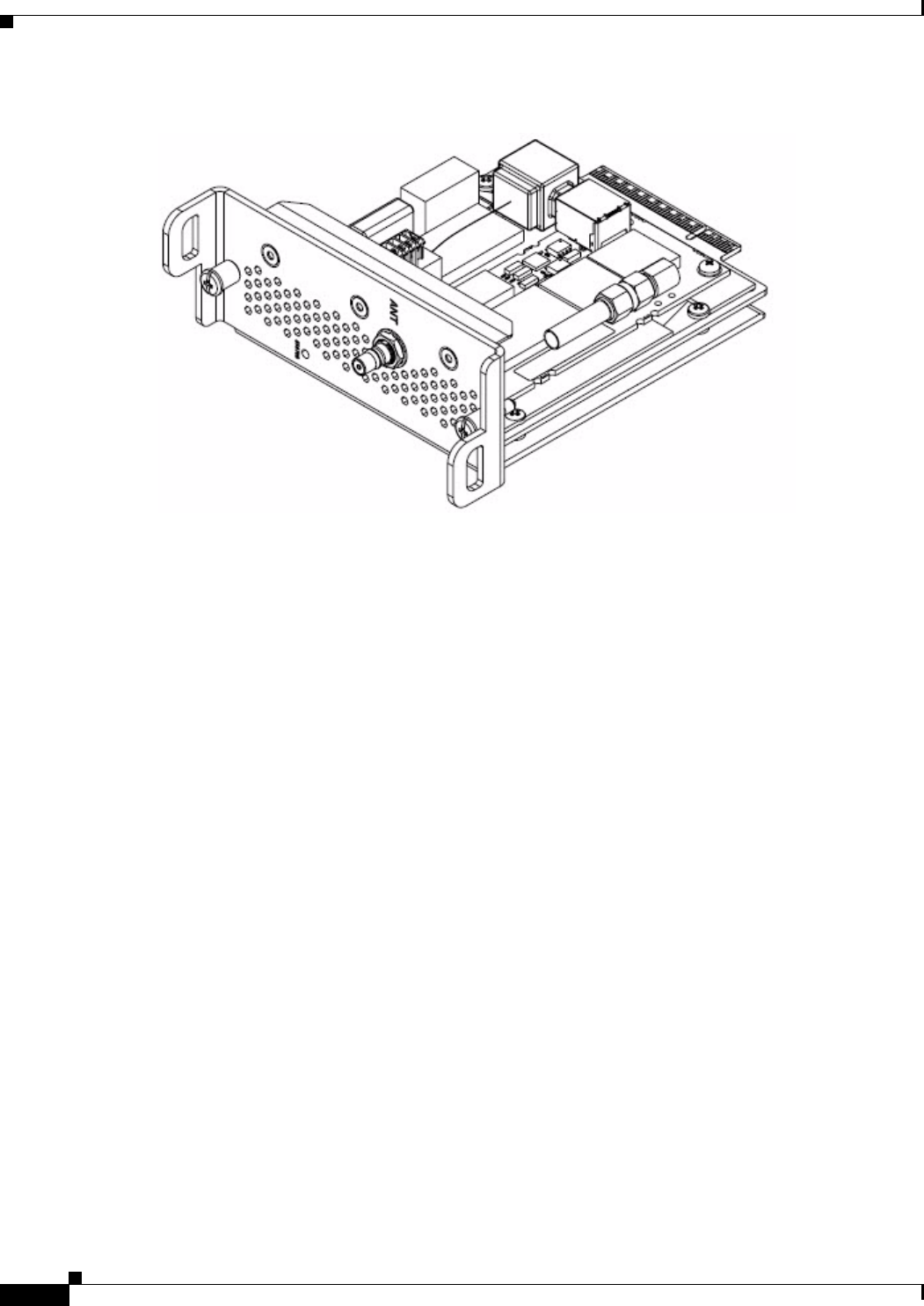
Kit Contents
Figure 1 Cisco Connected Grid WPAN Module
Kit Contents
For system requirements, important notes, limitations, open and resolved bugs, and last-minute
documentation updates, see the Release Notes on Cisco.com. For translations of the warnings that appear
in this document, see the Regulatory Compliance and Safety Information document for your router on
Cisco.com.
When using the online publications, see the documents that match the Cisco system software version
running on the WPAN module.
Features
The WPAN module provides the following functionality:
• Acts as bridge between the WPAN port manager and the radio module via the Cisco Connected Grid
1240 Router's FPGA module
• Monitors the health and of the WPAN module
• Resets and reprograms the WPAN module
• Collects statistics and status of the WPAN module
Hardware Overview
The WPAN module hardware is based on Itron’s Trifecta Communications Module, which contains a
Cortex-M3, microcontroller, Texas Instruments CC1101 RF Transceiver operating in the 900 MHz ISM
band, Semtech SX1781 PLL Frequency Synthesizer, and RF Micro Devices RF6559 front-end module.
This section covers the following topics:
FIRST REVIEW DRAFT—CISCO CONFIDENTIAL
3
Cisco Connected Grid WPAN Module for CGR1000 Series Installation and Configuration Guide
OL-26243-01
Hardware Overview
• Front Panel, page 3
• LED, page 3
• Supported Cisco Antenna, page 4
• Cisco Supported Cables, page 4
• Configuration, page 5
• Default Parameters, page 5
• Environmental Specifications, page 6
• Power Specifications, page 6
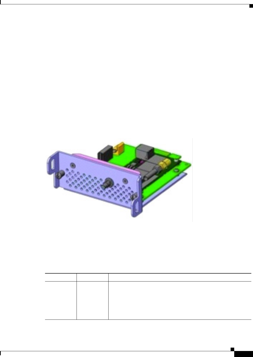
Front Panel
Figure 2 shows the front panel of the WPAN module.
Figure 2 Front Panel of the Cisco Connected Grid WPAN Module
LED
Table 1 lists the LED indicastor and describes the behavior. The LED provides a visual indicator of the
available services.
Ta b l e 1 LED Indicator
LED Name Color Description
Status Green Indicates the RF status:
• Off: Module is not powered
• On: System is functional - RF mesh interface is up (if installed)
• Blinking: Hardware is functional - RF mesh interface is up (if
installed)

FIRST REVIEW DRAFT—CISCO CONFIDENTIAL
4
Cisco Connected Grid WPAN Module for CGR1000 Series Installation and Configuration Guide
OL-26243-01
Hardware Overview
Supported Cisco Antenna
The antenna is connected to the TNC, panel-mount, 50 Ohm connector located on the faceplate of the
WPAN module.
For more information about antennas, including installation steps, see the Cisco Connected Grid 1240
Router Installation Guide.
Table 2 lists the Cisco antenna this is supported for use with the WPAN module and the Cisco Connected
Grid 1120 Router.
Cisco Supported Cables
Table 3 lists the external cable options, and internal cable/adapter available from Cisco for use with the
WPAN module.
Interfaces
The WPAN module includes the following physical interfaces to the host:
• Single RF Transceiver—supports IEEE 802.15.4g in the 915 MHz ISM. The RF transceiver is used
to provide mesh networking connectivity.
• Single Serial UART—used to communicate with the Cisco Connected Grid 1240 Router host
processor via the onboard FPGA I/O module, providing framing control and buffering for UART
data communications.
• GPIO—control and data communications
Ta b l e 2 CGR 1240 Supported Antennas and Cables for use with the WPAN Module
Description Outdoor Cable Antenna
• WPAN Module
• 10.5’or 17.5’ cable through
conduit
Single cable passes thru conduit
from inside to outside bldg.
900 MHz, 3G, 806-960 MHz,
1710-2700 MHz, Monopole
Antenna, Chassis Mounted,
Omni-directional,
ANT-MP-INT-OUT-M, qty 1
Table 3 Cisco External and Internal Cables for WPAN Module
External Cable Options Internal Cable/Adapter Antenna Options
• LMR-400-DB, 20’
CAB-L400-20-N-N
• LMR-600B-DB, 30’
CAB-L600-30-N-N
• LMR-100, 10.5”
CAB-L100-10-Q-M, qty 1
• LMR-100-17.5”
CAB-L100-17-Q-M, qty 1
• N Bulkhead adapters plus
lightning arrestors, qty 2
900 MHz ISM Band, Omni
Stick, ANT-RF-OMNI-OUT-N,
qty 1

FIRST REVIEW DRAFT—CISCO CONFIDENTIAL
5
Cisco Connected Grid WPAN Module for CGR1000 Series Installation and Configuration Guide
OL-26243-01
Hardware Overview
Configuration
The configuration parameters are set by the Connected Grid Network Management System (CG-NMS),
through a series of CLI commands. Statistics on netork traffic is also retrieved from the interface via the
RF port manager, through the use of the CLI.
Default Parameters
Table 4 lists the interface default values.
Table 5 lists the default frequencies for each channel.
Ta b l e 4 List of Interface Default Values
Parameters Default Value
Admin State Enabled
802.14.4 Raw Data Rates 155 kbps (78.6 kbps with FEC on by default)
RF Transmit Power 28 dBm
Channels 52 (frequency hopping)
Link Retransmission Retries 16
Mac Backoff Timer
Ta b l e 5 List of Default Frequencies for each Channel
Channel #
Channel f.
(MHz) Channel #
Channel f.
(MHz) Channel #
Channel f.
(MHz) Channel #
Channel f.
(MHz)
1 902.250 14 908.750 27 915.250 40 921.750
2 902.750 15 909.250 28 915.750 41 922.250
3 903.250 16 909.750 29 916.250 42 922.750
4 903.750 17 910.250 30 916.750 43 923.250
5 904.250 18 910.750 31 917.250 44 923.750
6 904.750 19 911.250 32 917.750 45 924.250
7 905.250 20 911.750 33 918.250 46 924.750
8 905.750 21 912.250 34 918.750 47 925.250
9 906.250 22 912.750 35 919.250 48 925.750
10 906.750 23 913.250 36 919.750 49 926.250
11 907.250 24 913.750 37 920.250 50 926.750
12 907.750 25 914.250 38 920.750 51 927.250
13 908.250 26 914.750 39 921.250 52 927.750

FIRST REVIEW DRAFT—CISCO CONFIDENTIAL
6
Cisco Connected Grid WPAN Module for CGR1000 Series Installation and Configuration Guide
OL-26243-01
Installing and Removing the Module
Environmental Specifications
Following are the operating temperature range for the router
Connected Grid 1120 Router: -40° C to 60° C (-40° F to 140° F)
Connected Grid 1240 Router: -35° C to 150° C (-31° F to 302° F)
Table 6 lists the environmental specifications for the Connected Grid WPAN Module.
Power Specifications
The Connected Grid WPAN Module has a 12V power rail and 3.3V standby power provided by the host
system.
Installing and Removing the Module
Before installing the WPAN module, verify the following guidelines have been met:
• Clearance to the I/O side view is such that the LED can be read
• Airflow around the WPAN module and through the vents is unrestricted
• Temperature around the unit does not exceed 140°F (60° C). If the WPAN module is installed in a
closed or multi-rack assembly, the temperature around it might be higher than normal room
temperature.
• Relative humidity around the WPAN module does not exceed 95% (non-condensing)
• Altitude at the installation site is not higher than 10,000 feet
• After replacing or installing a module in the router, you must update the label (on the router exterior)
that lists the module types contained in the router. The label must list the FCC ID number and the
IC Certification number for each module installed in the router.
Ta b l e 6 WPAN Module Environmental Specifications
Environmental—Operational Specifications
Temperature—standard range -5°C to 55°C (-41°F to 131°F)
Temperature—long term -40°C to 60°C (-40°F to 140°F)
Temperature—short term (up to 16 hours) -40°C and 95°C (-40°F to 195°F)
Altitude Up to 1500 meters
Humidity RH95% non condensed
Vibration 1.0 g from 1.0 to 150 Hz
Shock 30 G half sine 6 ms and 11 ms
Seismic GR63-Core, Zone 4

FIRST REVIEW DRAFT—CISCO CONFIDENTIAL
7
Cisco Connected Grid WPAN Module for CGR1000 Series Installation and Configuration Guide
OL-26243-01
Installing and Removing the Module
Installation Warning Statements
This section includes the basic installation warning statements. Translations of these warning statements
appear in the Regulatory Compliance and Safety Information for Cisco Connected Grid Router 1000
Series Routers documents.
Warning
This unit is intended for installation in restricted access areas. A restricted access area can be
accessed only through the use of a special tool, lock and key, or other means of security.
Statement 1017
Warning
Only trained and qualified personnel should be allowed to install, replace, or service this equipment.
Statement 1030
Warning
To prevent the system from overheating, do not operate it in an area that exceeds the maximum
recommended ambient temperature of:
140°F (60°C)
Statement 1047
Warning
This equipment is supplied as “open type” equipment. It must be mounted within an enclosure that is
suitably designed for those specific environmental conditions that will be present and appropriately
designed to prevent personal injury resulting from accessibility to live parts. The interior of the
enclosure must be accessible only by the use of a tool.
The enclosure must meet IP 54 or NEMA type 4 minimum enclosure rating standards.
Statement 1063
Warning
This equipment is intended to be grounded to comply with emission and immunity requirements.
Ensure that the switch functional ground lug is connected to earth ground during normal use.
Statement 1064
Warning
To prevent airflow restriction, allow clearance around the ventilation openings to be at least: 1.75 in.
(4.4 cm)
Statement 1076
Installing the WPAN Module
To install the module into an available slot in the Cisco Connected Grid 1120 Router or the Cisco
Connected Grid 1240 Router:
Caution The module can NOT be hot swapped—to install the module, you must first power down the module.
Step 1 Before you install (or remove) the Connected Grid WPAN Module from the host router, you must power
down the router as described in the Hardware Installation Guide of your router.
Step 2 Insert the WPAN module in the slot.
FIRST REVIEW DRAFT—CISCO CONFIDENTIAL
8
Cisco Connected Grid WPAN Module for CGR1000 Series Installation and Configuration Guide
OL-26243-01
Regulatory and Compliance Information
Step 3 Using a screwdriver, secure the two captive screws into place.
Removing the WPAN Module
To remove the WPAN module from a slot in the Cisco Connected Grid 1120 Router, or the Cisco
Connected Grid 1240 Router:
Caution The module can NOT be hot swapped—to install the module, you must first power down the module.
Step 1 Using a screwdriver, loosen the two captive screws on the Connected Grid WPAN Module.
Step 2 Gently pull the WPAN module out of the slot.
Regulatory and Compliance Information
For regulatory compliance and safety information for the WPAN module, refer to the Connected Grid
Router 2000 Series Regulatory Compliance and Safety Infomration document:
http://www.cisco.com/en/US/docs/routers/access/2000/CGR2010/hardware/rcsi/rcsiCGR2000series.html
Software Overview
The Connected Grid WPAN Module is configured using the Cisco Connected Grid 1240 Router system
software. This section covers the following topics:
• Prerequisites, page 9
• Configuring the Cell Relay Application, page 9
• Obtaining the ESN Number to Register the Router to the Collection Engine, page 10

FIRST REVIEW DRAFT—CISCO CONFIDENTIAL
9
Cisco Connected Grid WPAN Module for CGR1000 Series Installation and Configuration Guide
OL-26243-01
Software Overview
• Show Commands to Verify the Cell Relay, page 10
• Force Registration using the Command Line, page 11
• Change Communications Module UID from the FAR, page 12
• Debugging Commands to Verify the Cell Relay, page 12
• Additional Debugging Commands, page 13
• Sample Router Configuration, page 13
Prerequisites
Connecting to the console port of the Cisco Connected Grid 1240 Router dipslays the loading sequence.
Once the router has completed the boot process, the login prompt displays.
Note The system takes up to three minutes to come up after you intially login and start configuring the router.
Please wait for the prompt before continuing and running CLI commands.
Refer to the Cisco Connected Grid 1240 Router Configuration Guide for details on how to bring up and
log into the router..
Configuring the Cell Relay Application
This section contains information on enabling the Cell Relay and configuring the Collection Engine IP
address.
Note The configuration is this section is for release 3.7 only.
Enabling the Cell Relay
The Cell Relay is disabled by default, and is required to be enabled for configuration.
router# show feature
Feature Name Instance State
-------------------- -------- --------
…… <trimmed>
c1222r 1 disabled
…… <trimmed>
router# config terminal
Enter configuration commands, one per line. End with CNTL/Z.
Altamont37(config)# feature c1222r
Altamont37(config)# show feature
Feature Name Instance State
-------------------- -------- --------
…… <trimmed>
c1222r 1 enabled
…… <trimmed>

FIRST REVIEW DRAFT—CISCO CONFIDENTIAL
10
Cisco Connected Grid WPAN Module for CGR1000 Series Installation and Configuration Guide
OL-26243-01
Software Overview
Note After the Cell Relay is enabled, you need to wait approximately one minute for the Itron thread to be
initialized.
Configuring the Collection Engine IP Address
You are now ready to the configure the Collection Engine IP address:
router(config)# cl1222r master-relay-address 10.1.1.10
Obtaining the ESN Number to Register the Router to the Collection Engine
To successfully register the router to the Collection Engine, you need the ESN number for the router.
Based on this ESN number, you can create an Endpoint Definition File (XML file) to add the router into
the Collection Engine. Refer to Itron’s OPENWAY Collection Engine documents for more information
(https://itron.com/na/PublishedContent/OpenWay_Collection_Engine.pdf).
The following command is used to get the ESN number from the router:
router(config)# show c1222r info global
State:
Registered : No
CommModuleEnabled : Yes
ElectronicSerialNumber : 2.16.840.1.114416.3.8893.14692240
ApTitle :
Timers:
HeartbeatGoodFrequency : 300 secs
UplinkFailureDisableCommModulePeriod : 28800 secs
DatalinkDownResetCommModulePeriod : 60 mins
CommModuleStatisticsReadPeriod : 10 secs
RegistrationSendDelay : 0 secs
ExceptionHost:
ApTitle :
AckBroadcastFromExceptionHost : No
Build:
Version : 1.0.31.0 Oct 11 2011 08:12:51
CommModuleVersion : 14.58
router(config)#
Show Commands to Verify the Cell Relay
You can verify if the router was registered with the Collection Engine successfuly by using the
commands “show c1222r info globals”, and both “Registered” and “CommModuleEnabled” should
show as Yes.
router(config)# show c1222r info global
State:
Registered : Yes
CommModuleEnabled : Yes
ElectronicSerialNumber : 2.16.840.1.114416.3.8893.14692240
ApTitle : 2.16.124.113620.1.22.0.1.1.64.10081

FIRST REVIEW DRAFT—CISCO CONFIDENTIAL
11
Cisco Connected Grid WPAN Module for CGR1000 Series Installation and Configuration Guide
OL-26243-01
Software Overview
Timers:
HeartbeatGoodFrequency : 300 secs
UplinkFailureDisableCommModulePeriod : 28800 secs
DatalinkDownResetCommModulePeriod : 60mins
CommModuleStatisticsReadPeriod : 10 secs
RegistrationSendDelay : 0 secs
ExceptionHost:
ApTitle : 2.16.124.113620.1.22.0.1.1.64.33
AckBroadcastFromExceptionHost : No
Build:
Version : 1.0.9.0 Jul 29 201105:39:40
CommModuleVersion : 14.58
You can also verify if the master-relay address was configured properly with the following command:
router(config)# show c1222r info master-relay
MasterRelayAddress : 10.1.1.10
MasterRelayPriority : 1
MasterRelayPort : 1153
MasterRelayInboundConnected : Yes
MasterRelayOutboundConnected : No
You can also verify the comm-module information (configuration and status) with the following
command:
router(config)# show c1222r info comm-module
State:
Index : 1
Name : TFC CellRelay
Enabled : Yes
RouteToUnknownMAC : Yes
Timers:
NETRDelay : 5 secs
NETTDelay : 20 secs
Misc:
IntervalSinceEnabled : Tue Oct 4 13:53:24 2011
IntervalSinceDisabled : -
LastMessageSent : Tue Oct 4 14:00:38 2011
CommModuleLastMessageReceived : Tue Oct 4 14:03:39 2011
IntervalSinceDatalinkReset : 2957 secs
IntervalSinceBaudrateChange : 2933 secs
IntervalSinceStatisticsRead : 5 secs
MessageQueueDepth : 0
LastACSEMessageFailCode : 0
IntervalSinceLastACSEMessageFail : -
Force Registration using the Command Line
If the Cell Relay did to register to the Collection Engine, you can force registration with the following
command to ensure there are two TCP connection to the Collection Engine:
router(config)# show sockets connection tcp
:
tcp ESTABLISHED 0 25.0.0.2(1153)
default 0 10.1.1.10(3137)
tcp ESTABLISHED 0 25.0.0.2(34118)

FIRST REVIEW DRAFT—CISCO CONFIDENTIAL
12
Cisco Connected Grid WPAN Module for CGR1000 Series Installation and Configuration Guide
OL-26243-01
Software Overview
default 0 10.1.1.10(1153)
You can now force registration:
router(config)# test c1222r register
Change Communications Module UID from the FAR
You can change the UID from the FAR to synchronize all the meters with the FAR, using the same UID:
router# sh c1222r info rflanconfig
MacAddress: 7647340
UtilityId: a6
router# conf t
Enter configuration commands, one per line. End with CNTL/Z.
router(config)# c1222r rflanconfig utility-id 0xC9
SetUtilityID: OK
Scheduled comm module reset. Takes about 1 minute to complete.
router(config)# sh c1222r info rflanconfig
MacAddress: 7647340
UtilityId: c9
router(config)#
Note The MAC address is displayed in decimal format and must be converted into hex format.
Debugging Commands to Verify the Cell Relay
Use the following commands to verify the Cell Relay:
router(config)# logging level c1222r 7
router(config)# logging logfile <filename> 7
router(config)# show logging level c1222r
Facility Default Severity Current Session Severity
-------- ---------------- ------------------------
c1222r 3 7
0(emergencies) 1(alerts) 2(critical)
3(errors) 4(warnings) 5(notifications)
6(information) 7(debugging)
router(config)#
Use the following commands to verify the logs:
router(config)# show logging logfile | include ITRON
2009 Jan 4 22:06:21 Altamont37-FAR1 %C1222R-1-ITRON_SDK_LOG_ALERT: Configuration file not
found. Using defaults.
2009 Jan 4 22:06:22 Altamont37-FAR1 %C1222R-2-ITRON_SDK_LOG_CRIT: Unable to open UART
file /dev/ttyUSB0. Errno=19
2009 Jan 4 22:18:51 Altamont37-FAR1 %C1222R-4-ITRON_SDK_LOG_WARNING: TCP connection to
10.1.1.10 timed out waiting for ESTABLISHED state
Use show logging logfile | last <# of lines> to get the last number of lines in the logfile. The
following is the example to get the last 10 lines in the logfile:
router(config)# show logging logfile | last 10

FIRST REVIEW DRAFT—CISCO CONFIDENTIAL
13
Cisco Connected Grid WPAN Module for CGR1000 Series Installation and Configuration Guide
OL-26243-01
Software Overview
Additional Debugging Commands
All debug commands can be enabled using the debug c1222r command followed by the area of interest.
To find out details on the available debug command options, enter debug c1222r ?.
router(config)# debug c1222r warning
You can check to see if a debugging option is enabled or disabled by using show debug:
router(config)# show debug c1222r
C1222R Daemon:
MTS Receive Packets debugging is on
MTS Transmit Packets debugging is on
MTS Receive Packet header/payload debugging is on
MTS Transmit Packet header/payload debugging is on
High Availability debugging is on
Event debugging is on
Error debugging is on
Warning debugging is on
Trace debugging is on
Trace Detail debugging is on
Demux debugging is on
Dequeue debugging is on
Sample Router Configuration
router# show running-config
!Command: show running-config
!Time: Tue Oct 4 15:23:02 2011
version 5.2(1)
logging level feature-mgr 0
hostname Altamont37
vdc wireless-far id 1
limit-resource vlan minimum 16 maximum 4094
limit-resource vrf minimum 2 maximum 4096
limit-resource u4route-mem minimum 9 maximum 9
limit-resource u6route-mem minimum 24 maximum 24
limit-resource m4route-mem minimum 58 maximum 58
limit-resource m6route-mem minimum 8 maximum 8
feature telnet
feature crypto ike
crypto ike domain ipsec
policy 10
authentication pre-share
group 5
key Cisco123 address 11.0.0.1
key Cisco123 address 192.10.0.1
key Cisco123 address 192.168.168.1
feature scheduler
feature ospf
feature netflow
feature dhcp
feature tunnel
feature crypto ipsec virtual-tunnel
feature c1222r
logging level ntp 7
logging level evmc 7

FIRST REVIEW DRAFT—CISCO CONFIDENTIAL
14
Cisco Connected Grid WPAN Module for CGR1000 Series Installation and Configuration Guide
OL-26243-01
Software Overview
logging level evms 7
logging level vshd 7
logging level wifipm 2
logging level netstack 3
username adminbackup password 5 ! role network-operator
username admin password 5 $1$clxfU5Ae$auC5BarZetpQMhU4gjA5a. role network-admin
no password strength-check
ip domain-lookup
copp profile strict
snmp-server user admin network-admin auth md5 0xa4495f08940116511391f04d149fc878
priv 0xa4495f08940116511391f04d149fc878 localizedkey
rmon event 1 log trap public description FATAL(1) owner PMON@FATAL
rmon event 2 log trap public description CRITICAL(2) owner PMON@CRITICAL
rmon event 3 log trap public description ERROR(3) owner PMON@ERROR
rmon event 4 log trap public description WARNING(4) owner PMON@WARNING
rmon event 5 log trap public description INFORMATION(5) owner PMON@INFO
ntp distribute
ntp peer 10.1.1.99
ntp source-interface Ethernet2/1
ntp commit
vrf context management
track 1 ip route 20.0.0.1/32 reachability
delay up 120 down 120
crypto ipsec transform-set MyTransformSet esp-aes 128 esp-sha1-hmac
crypto ipsec profile MyProfile
set transform-set MyTransformSet
vlan 1
service dhcp
ip dhcp relay
wifi ssid blah
authentication open
interface Tunnel15
ip address 23.0.5.2/30
ip ospf cost 100
ip ospf dead-interval 20
ip ospf hello-interval 5
ip ospf mtu-ignore
ip router ospf 2 area 0.0.0.2
tunnel mode ipsec ipv4
tunnel source wimax5/1
tunnel destination 192.10.0.1
no keepalive
tunnel protection ipsec profile MyProfile
no shutdown
interface Tunnel16
ip address 23.0.6.2/30
ip ospf cost 500
ip ospf dead-interval 20
ip ospf hello-interval 5
ip ospf mtu-ignore
ip router ospf 2 area 0.0.0.2
tunnel mode ipsec ipv4
tunnel source cellular3/1
tunnel destination 192.168.168.1
no keepalive
tunnel protection ipsec profile MyProfile
no shutdown

FIRST REVIEW DRAFT—CISCO CONFIDENTIAL
15
Cisco Connected Grid WPAN Module for CGR1000 Series Installation and Configuration Guide
OL-26243-01
Software Overview
interface Tunnel17
ip address 23.0.7.2/30
ip ospf cost 1000
ip ospf dead-interval 20
ip ospf hello-interval 5
ip ospf mtu-ignore
ip router ospf 2 area 0.0.0.2
tunnel mode ipsec ipv4
tunnel source Ethernet2/7
tunnel destination 11.0.0.1
no keepalive
tunnel protection ipsec profile MyProfile
no shutdown
interface Tunnel111
ip address 2.2.2.2/24
ipv6 address 2001:a:a:abcd::2/64
tunnel source Ethernet2/7
tunnel destination 11.0.0.1
no keepalive
interface dialer1
dialer persistent
dialer pool 1
dialer string gsm1
interface Ethernet2/1
mac-address 0022.bde0.2f91
ip address 172.27.166.60/8
no shutdown
interface Ethernet2/2
mac-address 0022.bde0.2f92
no shutdown
interface Ethernet2/3
mac-address 0022.bde0.2f93
interface Ethernet2/4
mac-address 0022.bde0.2f94
ip address dhcp
no shutdown
ip dhcp relay address 19.0.0.100
interface Ethernet2/5
mac-address 0022.bde0.2f95
interface Ethernet2/6
mac-address 0022.bde0.2f96
ipv6 address 80::1/64
no shutdown
interface Ethernet2/7
ip address 11.0.0.11/16
no shutdown
interface Ethernet2/8
mac-address 0022.bde0.2f98
interface loopback0
ip address 20.0.0.2/24
ip router ospf 2 area 0.0.0.2
interface loopback5

FIRST REVIEW DRAFT—CISCO CONFIDENTIAL
16
Cisco Connected Grid WPAN Module for CGR1000 Series Installation and Configuration Guide
OL-26243-01
Software Overview
interface cellular3/1
no shutdown
dialer pool-member 1
interface wimax5/1
no shutdown
scan-list aaa
ip address 192.10.0.21/16
interface wpan4/1
panid 0
interface wifi2/1
clock timezone PST -8 0
clock summer-time PDT 2 Sun Mar 02:00 1 Sun Nov 02:00 60
line console
exec-timeout 0
line vty
exec-timeout 0
router ospf 2
ip route 10.1.1.0/24 20.0.0.1
ip route 128.0.0.0/8 172.27.166.1
ip route 171.0.0.0/8 172.27.166.1
ip route 172.0.0.0/8 172.27.166.1
ip route 182.0.0.0/8 25.0.0.1
ipv6 route 2001:a:a:abcd::/127 Tunnel111
event manager environment bh_iflist2 "tunnel1 tunnel15 tunnel16"
event manager environment bh_down_reset_thresh "30"
event manager environment bh_iflist "cell3/1 wimax5/1"
event manager environment bh_down_reload_thresh "60"
event manager environment bh_flap_thresh_cnt "10"
event manager environment bh_flap_thresh_duration "15"
event manager environment bhmgr_track_obj_instance "1"
event manager environment eem_dbg_level "1"
event manager applet bhmgrbhdown
event track 1 state down
action 1.0 syslog priority critical msg Backhaul is down
action 2.0 cli tclsh bootflash:bhmgr.tcl bhmgr_process_bh_down
action 3.0 cli command maximum-timeout
event manager applet bhmgrbhup
event track 1 state up
action 1.0 syslog priority errors msg Backhaul is up
action 2.0 cli tclsh bootflash:bhmgr.tcl bhmgr_process_bh_up
action 3.0 cli command maximum-timeout
event manager applet shutnoshutif
event track 15 state down
action 1.0 syslog priority critical msg Wimax went down - doing shut/no shut o
chat-script gsm1 PROFILE1
wimax scan-list aaa
channel index 1 frequency 2550000 bandwidth 10000
nap id 00:00:01 priority 1 channel-index 1
nsp id 00:00:01 home
cgdm
logging logfile test 7
logging monitor 7
logging level user 2
scheduler job name bhmgr_monitor
tclsh bootflash:/bhmgr.tcl bhmgr_monitor

FIRST REVIEW DRAFT—CISCO CONFIDENTIAL
17
Cisco Connected Grid WPAN Module for CGR1000 Series Installation and Configuration Guide
OL-26243-01
Additional References
end-job
scheduler schedule name bhmgr_monitor_schedule
job name bhmgr_monitor
time start 2011:08:30:16:09 repeat 0:0:1
router#
Additional References
Consult the following resources for related information about the Connected Grid WPAN Module for
technical assistance.
Hardware Overview and Installation
• Cisco Connected Grid Modules
http://www.cisco.com/en/US/products/ps10984/prod_module_series_home.html
• Cisco CGR 1240 Hardware Installation Guide
• Cisco CGR 1120 Hardware Installation Guide
• Cisco CGS1240 Getting Started Guide
Supported Cisco Antennas and Accessories
• Cisco 3G Omnidirectional Outdoor Antenna (3G-ANTM-OUT-OM)
http://www.cisco.com/en/US/docs/routers/access/wireless/hardware/notes/ant3gom.html
• Cisco Multiband Omnidirectional Panel-Mount Antenna (3G-ANTM-OUT-LP)
http://www.cisco.com/en/US/docs/routers/access/wireless/hardware/notes/antcmLP.html
Cisco System Software Commands
• Cisco System Software
http://www.cisco.com/en/US/products/ps9372/tsd_products_support_series_home.html
• Configuring Cisco EHWIC-3G-EDVO-x
http://www.cisco.com/en/US/docs/routers/access/1800/1861/software/feature/guide/mrwls_evdo.h
tml
• Cisco 1000 Series Connected Grid Routers Unicast Routing Software Configuration Guide
Regulatory, Compliance, and Safety Information
• Cisco Network Modules and Interface Cards Regulatory Compliance and Safety Information
http://www.cisco.com/en/US/docs/routers/access/interfaces/rcsi/IOHrcsi.html

FIRST REVIEW DRAFT—CISCO CONFIDENTIAL
18
Cisco Connected Grid WPAN Module for CGR1000 Series Installation and Configuration Guide
OL-26243-01
Technical Assistance
Technical Assistance
The Cisco Support and Documentation website provides online resources to download documentation,
software, and tools. Use these resources to install and configure the software and to troubleshoot and
resolve technical issues with Cisco products and technologies. Access to most tools on the Cisco Support
and Documentation website requires a Cisco.com user ID and password.
http://www.cisco.com/cisco/web/support/index.html
Cisco and the Cisco Logo are trademarks of Cisco Systems, Inc. and/or its affiliates in the U.S. and other countries. A listing of Cisco's trademarks
can be found at www.cisco.com/go/trademarks. Third party trademarks mentioned are the property of their respective owners. The use of the word
partner does not imply a partnership relationship between Cisco and any other company. (1005R)
Any Internet Protocol (IP) addresses and phone numbers used in this document are not intended to be actual addresses and phone numbers. Any
examples, command display output, network topology diagrams, and other figures included in the document are shown for illustrative purposes only.
Any use of actual IP addresses or phone numbers in illustrative content is unintentional and coincidental.
© 2011 Cisco Systems, Inc. All rights reserved.