Cisco Systems ALTMT0556 Utility Meter Monitoring System User Manual cgr1240hig
Cisco Systems Inc Utility Meter Monitoring System cgr1240hig
Contents
- 1. user manual pt 1
- 2. 3G module manual
- 3. 900 MHz module manual
- 4. user manual pt 2
user manual pt 2

DEC. 2011—EFT REVIEW DRAFT—CISCO CONFIDENTIAL
6-9
Cisco 1240 Connected Grid Router Hardware Installation Guide
OL-26223-01
Chapter 6 Installing the Router
Basic Hardware Installation
Use the show interface Command
To verify that the router has been successfully installed and connected to the network, use the show
interface command to confirm that the router Ethernet interface is up.
CGR1240> show interface
Ethernet0 is up, line protocol is up
Hardware is Cisco, address is 0019.076c.1a78 (bia 0019.076c.1a78)
Internet address is 192.0.2.111/23
MTU 1500 bytes, BW 10000 Kbit, DLY 1000 usec, rely 255/255, load 1/255
Encapsulation ARPA, loopback not set, keepalive set (10 sec)
ARP type: ARPA, ARP Timeout 04:00:00
Last input 00:00:00, output 00:00:00, output hang never
Last clearing of "show interface" counters never
Queueing strategy: fifo
Output queue 0/40, 0 drops; input queue 5/75, 32 drops
5 minute input rate 10000 bits/sec, 27 packets/sec
5 minute output rate 10000 bits/sec, 26 packets/sec
16076431 packets input, 1280716531 bytes, 27 no buffer
Received 1809290 broadcasts, 0 runts, 0 giants
1105 input errors, 0 CRC, 0 frame, 0 overrun, 1105 ignored, 0 abort
0 input packets with dribble condition detected
16196175 packets output, 1011044938 bytes, 0 underruns
19 output errors, 184 collisions, 3 interface resets
0 babbles, 0 late collision, 1474 deferred
19 lost carrier, 0 no carrier
0 output buffer failures, 0 output buffers swapped out
Serial0 is administratively down, line protocol is down
Hardware is HD64570
MTU 1500 bytes, BW 1544 Kbit, DLY 20000 usec, rely 255/255, load 1/255
Encapsulation HDLC, loopback not set, keepalive set (10 sec)
Last input never, output never, output hang never
Last clearing of "show interface" counters never
Input queue: 0/75/0 (size/max/drops); Total output drops: 0
Queueing strategy: weighted fair
Output queue: 0/64/0 (size/threshold/drops)
Conversations 0/0 (active/max active)
Reserved Conversations 0/0 (allocated/max allocated)
5 minute input rate 0 bits/sec, 0 packets/sec
5 minute output rate 0 bits/sec, 0 packets/sec
0 packets input, 0 bytes, 0 no buffer
Received 0 broadcasts, 0 runts, 0 giants
0 input errors, 0 CRC, 0 frame, 0 overrun, 0 ignored, 0 abort
0 packets output, 0 bytes, 0 underruns
0 output errors, 0 collisions, 1 interface resets
0 output buffer failures, 0 output buffers swapped out
0 carrier transitions
DCD=down DSR=down DTR=down RTS=down CTS=down
For more information about using the show interface command, see the Cisco 1000 Series Connected
Grid Routers Software Configuration Guide.

DEC. 2011—EFT REVIEW DRAFT—CISCO CONFIDENTIAL
6-10
Cisco 1240 Connected Grid Router Hardware Installation Guide
OL-26223-01
Chapter 6 Installing the Router
Additional Router Connections
Additional Router Connections
This section provides information about making other, additional router cable connections. Follow the
procedures in this section based on your network configuration and requirements. This section contains
these procedures:
• External Connections and Chassis Cable Ports, page 6-10
• Using Cable Glands, page 6-11
• Connecting the Console Port, page 6-15
• Connecting the Serial Port, page 6-16
• Connecting the USB Ports, page 6-17
• Connecting the SFP Ports, page 6-18
• Connecting the Ethernet Ports, page 6-20
• Connecting the Alarm Port, page 6-22
• Connecting the IRIG-B Port, page 6-23
External Connections and Chassis Cable Ports
When connecting the router internal ports to external cables or exterior devices, you must thread the
router cables through the chassis cable ports designated for this purpose. Some chassis ports are reserved
for specific cables and remaining ports can be used based on your network configuration and cabling
requirements.
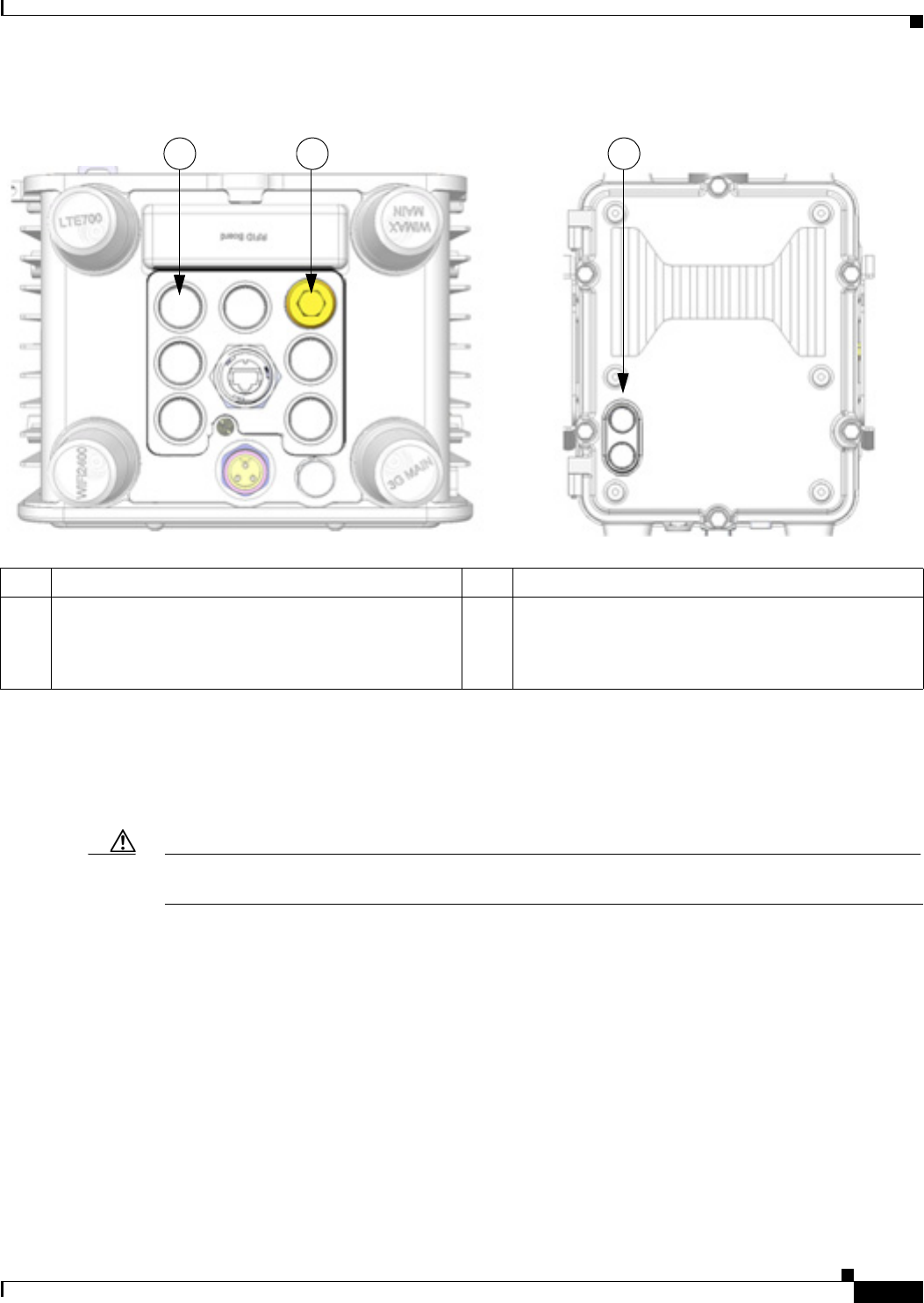
There are nine cable ports on the chassis base and two ports on the chassis door (Figure 6-8). Some ports
are reserved for a specific cables types, as indicated Figure 6-8.
Caution When you make router cable connections through these ports, you must use cable glands as described in
Using Cable Glands, page 6-11, to protect the router interior from environmental elements, including
moisture, heat, cold, and dust. Failure to use cable glands with the chassis cable ports can result in
damage to the router.
DEC. 2011—EFT REVIEW DRAFT—CISCO CONFIDENTIAL
6-11
Cisco 1240 Connected Grid Router Hardware Installation Guide
OL-26223-01
Chapter 6 Installing the Router
Additional Router Connections
Figure 6-8 Chassis Cable Ports—For Cabling to External Connectors or Devices
Using Cable Glands
This section describes how to use cable glands with router cables that are threaded through the chassis
cable ports that are described in External Connections and Chassis Cable Ports, page 6-10.
Caution The cable glands must be used for all cables that are threaded through the router chassis cable ports to
prevent exposing the router interior to environmental elements.
Ordering Cisco Cable Glands
You can order a cable gland kit from Cisco using the model number CGR-IP67GLAND. Each kit
contains one cable gland. See the chapter Router Hardware Description for detailed information about
this part.
Tools You Supply
You must supply a 13-mm box-end wrench or socket set to install the cable glands on the router.
Item Description Item Description
1These two ports on the router base are reserved for SPF
module cables. One of these ports is shown with the
liquid tight seal that must be used when the port is not
in use.
2These two ports on the router door are reserved for
non-Cisco module cables.
1 1 2
DEC. 2011—EFT REVIEW DRAFT—CISCO CONFIDENTIAL
6-12
Cisco 1240 Connected Grid Router Hardware Installation Guide
OL-26223-01
Chapter 6 Installing the Router
Additional Router Connections
Cable Glands Description
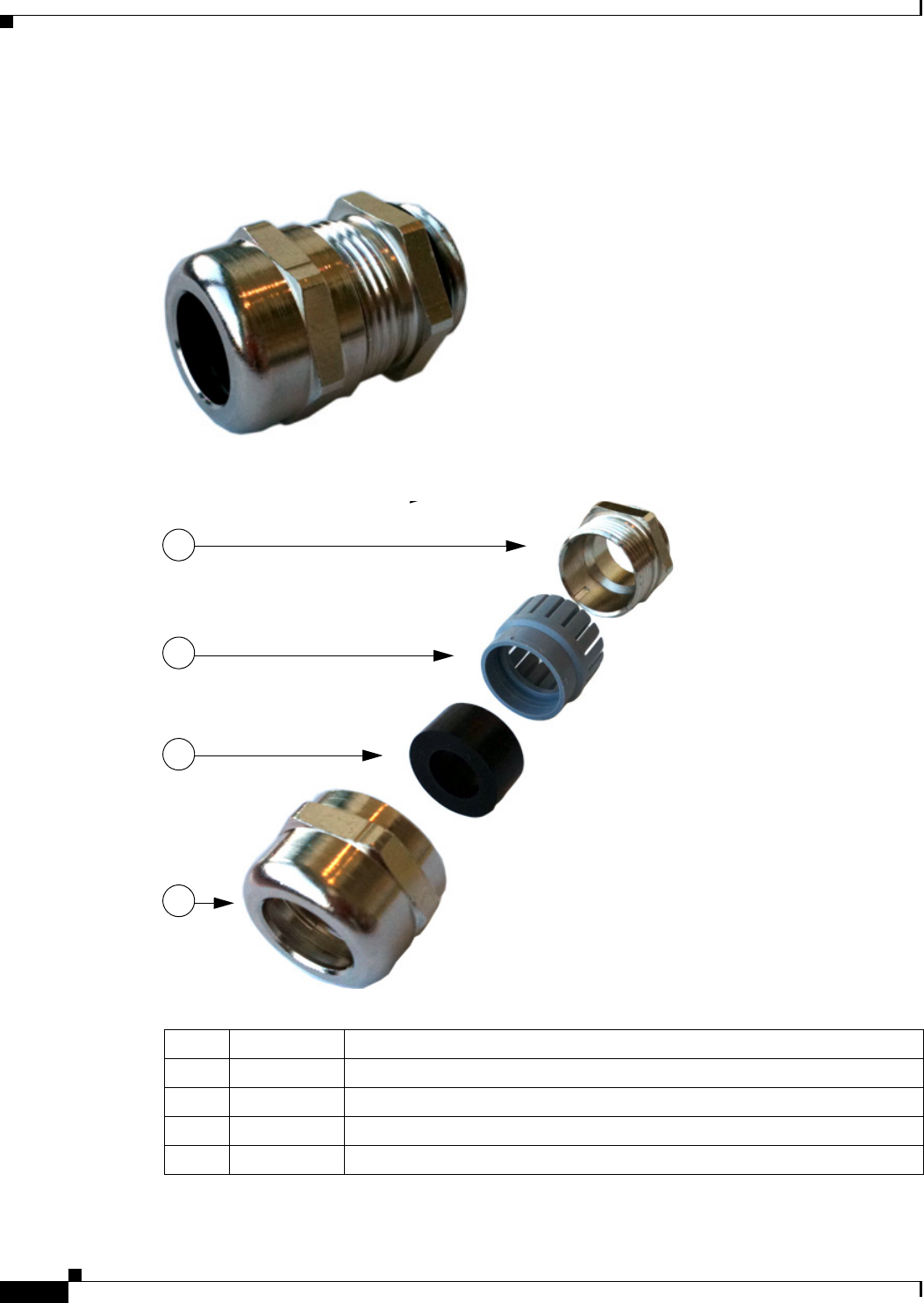
Figure 6-9 Cable Glands, Assembled
Figure 6-10 Cable Gland Components
Item Name Description
1Adapter Connects directly to the chassis cable port on the router.
2Grommet Secures the split gasket over the cable
3Split gasket Fits over the cable and creates an liquid-tight seal inside the glands.
4Cap Fits over gasket-and-cable assembly and connects it to the chassis cable port.
4
3
2
1

DEC. 2011—EFT REVIEW DRAFT—CISCO CONFIDENTIAL
6-13
Cisco 1240 Connected Grid Router Hardware Installation Guide
OL-26223-01
Chapter 6 Installing the Router
Additional Router Connections
Cable Requirements
Cables used with the cable glands should meet the following criteria:
• Outdoor-rated
• UV-stabilized
• Plenum-rated
• Minimum 1/2 in. (12.7 mm) in diameter
Caution Cables must be a minimum of 1/2 in. in diameter to create an adequate seal within the cable glands.
Using smaller cables could result in an inadequate seal and therefore expose the router interior to
environmental elements.
Cable Glands Installation Steps
Follow these steps for every cable that you will connect through the chassis cable ports on the router.
Step 4 and Step 5 can be done ahead of time and the prepared cable gland assembly can be transported
to the router installation site.
The cable glands components referred to in this section are shown in Figure 6-10.
Note Figure 6-12 shows an Ethernet cable but the steps are the same for all cable types.
Step 1 Verify the cable you are using meets the requirements described in Cable Requirements, page 6-13.
Step 2 Remove the liquid tight-seal from the port on the router. Use the 13-mm wrench if needed.
The router is shipped with liquid tight seals in unused ports. Figure 6-8 illustrates a liquid tight seal.
Step 3 Use your hands to attach the cable glands adapter (item 1 in Figure 6-10) into the chassis cable port on
the router (Figure 6-11).
Step 4 Thread the following cable glands components over the cable in this order (Figure 6-12):
1. Cap
2. Split gasket
3. Grommet
Step 5 Slide the split gasket along the cable and into the grommet, pressing firmly to ensure the gasket is
completely seated in the grommet.
Step 6 Thread the connector-end of the cable through the router port and insert it into the corresponding router
connector.
Step 7 Slide the cap along the cable, over the grommet, and then over the router port. Hand-tighten, then use
the 13-mm wrench to tighten to 6-7 foot-pounds of torque.
DEC. 2011—EFT REVIEW DRAFT—CISCO CONFIDENTIAL
6-14
Cisco 1240 Connected Grid Router Hardware Installation Guide
OL-26223-01
Chapter 6 Installing the Router
Additional Router Connections
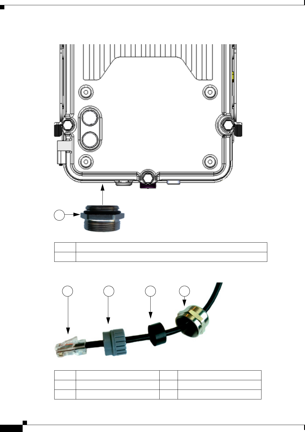
Figure 6-11 Attach Adapter to Chassis Cable Port on Router Base
Figure 6-12 Cable Glands Components Threaded on Cable
Item Description
1Attach cable glands adapter to any compatible cable port on the router.
1
Item Description Item Description
1Cable connector (to router) 3Split gasket
2Grommet 4Cap
1 2 3 4
DEC. 2011—EFT REVIEW DRAFT—CISCO CONFIDENTIAL
6-15
Cisco 1240 Connected Grid Router Hardware Installation Guide
OL-26223-01
Chapter 6 Installing the Router
Additional Router Connections
Connecting the Console Port
About
To configure the router through the Cisco IOS command-line interface (CLI), you must establish a
connection between the router console port and either a terminal or a PC. The console port is located on
the router exterior (Figure 6-13) and is labeled CON.
Use this port to connect a PC terminal, enabling you to log directly into the router system software to
perform configuration or other commands.
Caution The console port does not support cable glands. When a cable is connected to this port, the router interior
is exposed to environmental elements, which can damage the port and the router interior. This port
should be exposed only during terminal sessions, when a cable is connected to the port. This port should
never be left unattended when in use.
Figure 6-13 Console Port Location
Connecting
This section describes how to connect a PC terminal to the console port.
When a terminal is connected to the console port, you can connect directly to the router and configure
it. You can connect a PC terminal to this port while the router is operating normally.

DEC. 2011—EFT REVIEW DRAFT—CISCO CONFIDENTIAL
6-16
Cisco 1240 Connected Grid Router Hardware Installation Guide
OL-26223-01
Chapter 6 Installing the Router
Additional Router Connections
To connect a PC terminal to the router, you must provide:
• RJ-45-to-RJ-45 rollover cable
• One of the following adapters, depending on the device port: RJ-45-to-DB-25 female DTE adapter,
RJ-45-to-DB-9 female DTE adapter (labeled TERMINAL), or USB-to-DB-9 adapter.
Follow these steps to connect a PC or PC terminal to the console port:
Step 1 Connect one end of the RJ-45 cable to the console port on the router.
Step 2 Connect the adapter you provide to the other end of the RJ-45 cable.
Step 3 Connect the adapter end of the cable to the router.
Related Information
• For information about starting a terminal session over the console port with Microsoft Windows,
Mac OS X, or Linux, see the appendix Starting a Router Terminal Session.
• For more information about this port, see the chapter Router Hardware Description.
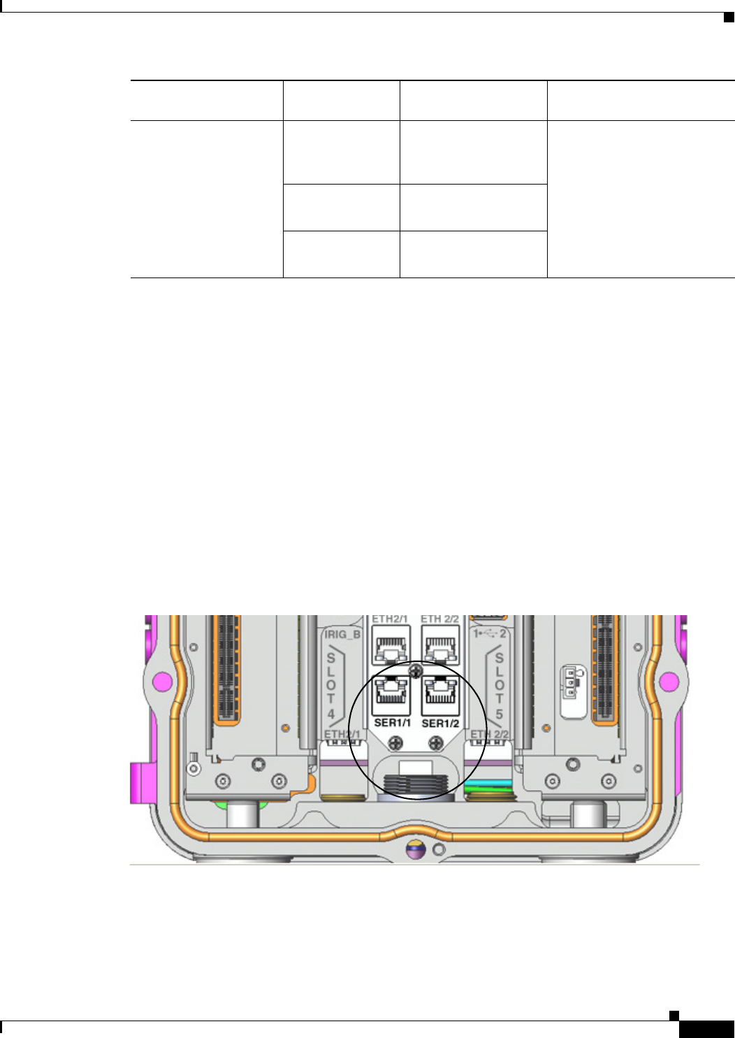
Connecting the Serial Port
Note Currently not supported. This hardware feature will be supported in a future software release.
About
Before you connect a device to the router serial port (Figure 6-14), you need to know the following:
• Type of device, data terminal equipment (DTE) or data communications equipment (DCE), you are
connecting to the synchronous serial interface
• Type of connector, male or female, required to connect to the device
• Signaling standard required by the device
These are the most common devices connected to the router serial ports:
Serial Device Network Options
Network Encapsulation
(Framing) Network Type
Asynchronous modem Asynchronous
dial-up line
Point-to-Point (PPP) Remote location to data center
DEC. 2011—EFT REVIEW DRAFT—CISCO CONFIDENTIAL
6-17
Cisco 1240 Connected Grid Router Hardware Installation Guide
OL-26223-01
Chapter 6 Installing the Router
Additional Router Connections
Connecting
• You must provide or purchase separately the correct serial cable. The cable does not ship with the
router. Contact your Cisco reseller to purchase the correct cable from Cisco.
• You can connect a device to this port while the router is operating normally.
• The serial ports are labeled SER 1/1 and SER 1/2.
• When connecting the serial ports to devices, you must use cable glands and thread cables through
the chassis cable ports on the router. See External Connections and Chassis Cable Ports, page 6-10
for more information.
Related Information
For more information about this port, including supported standards and signaling, see the chapter
Router Hardware Description.
Figure 6-14 Serial Port Location
Channel service
unit/data service unit
(CSU/DSU)
Synchronous
leased line
High-Level Data Link
Control (HDLC) or
PPP
Remote location to data center
Frame Relay Frame Relay
X. 25 X. 25
Serial Device Network Options
Network Encapsulation
(Framing) Network Type
DEC. 2011—EFT REVIEW DRAFT—CISCO CONFIDENTIAL
6-18
Cisco 1240 Connected Grid Router Hardware Installation Guide
OL-26223-01
Chapter 6 Installing the Router
Additional Router Connections
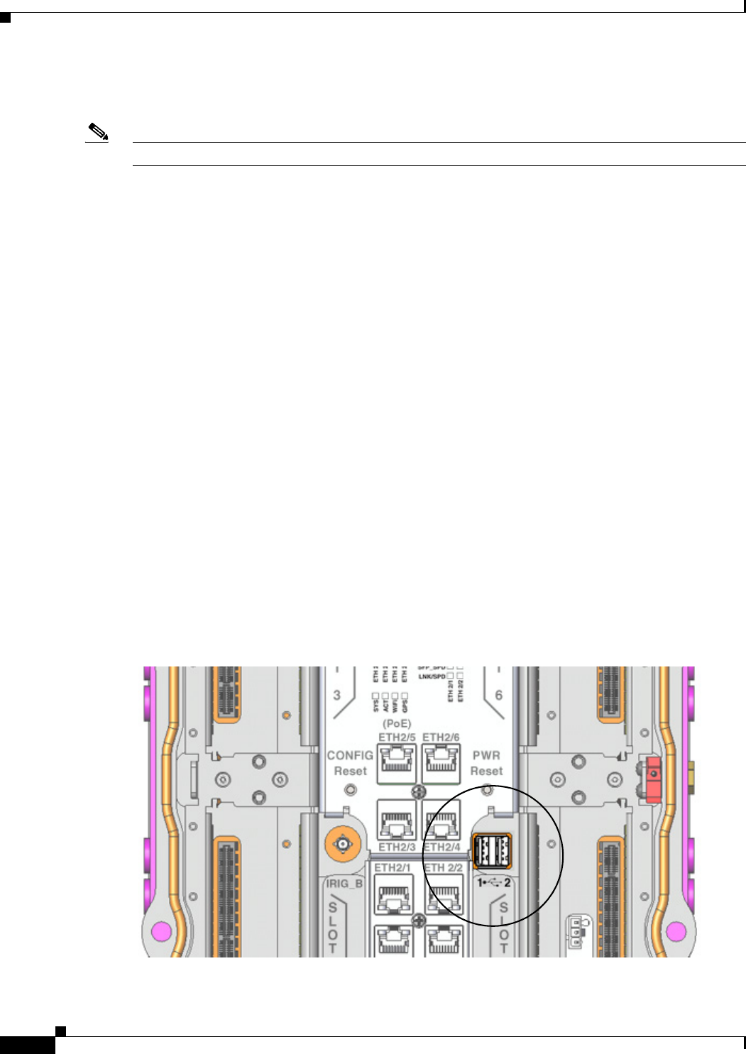
Connecting the USB Ports
Note Currently not supported. This hardware feature will be supported in a future software release.
About
You can connect up to two optional USB devices to the router USB ports (Figure 6-15), which will
provide power to the USB devices. You can also connect USB devices that are powered by an external
source, such as an AC adapter or batteries.
Connecting
• You can connect devices to these ports while the router is operating normally.
• The USB ports are labeled 1 and 2 (with a USB icon).
• Depending on the USB devices you connect to these ports, you might require a USB extension cable
to connect devices to these ports.
• To prevent connected USB devices from being stolen or accidently removed, secure any connected
USB device with a locking mechanism designed for this purpose.
• When connecting to external USB devices, you must use cable glands and thread USB cables
through the chassis cable ports on the router. See External Connections and Chassis Cable Ports,
page 6-10 for more information
Related Information
For detailed information about these ports, including supported USB standards and power output, see
the chapter Router Hardware Description.
Figure 6-15 USB Port Location
DEC. 2011—EFT REVIEW DRAFT—CISCO CONFIDENTIAL
6-19
Cisco 1240 Connected Grid Router Hardware Installation Guide
OL-26223-01
Chapter 6 Installing the Router
Additional Router Connections
Connecting the SFP Ports
About
Small Form-Factor Pluggable (SFP) modules are devices that plug into the router SFP connectors shown
in Figure 6-16. The transceiver connects the electrical circuitry of the module with the optical or copper
network.
The SFP module used on each port must match the wavelength specifications on the other end of the
cable, and the cable must not exceed the stipulated cable length for reliable communications.
Use only Cisco SFP transceiver modules with the router. Each SFP transceiver module supports the
Cisco Quality Identification (ID) feature which allows a Cisco switch or router to identify and validate
that the transceiver module is certified and tested by Cisco.
Warning
Class 1 laser product.
Statement 1008
Caution Do not remove the dust plugs from the fiber-optic SFP module port or the rubber caps from the
fiber-optic cable until you are ready to connect the cable. The plugs and caps protect the SFP module
ports and cables from contamination and ambient light.
Caution Cisco recommends that you not install or remove the SFP module while the fiber-optic cable is attached
to it because of the potential damage to the cables, to the cable connector, or to the optical interfaces in
the SFP module. Disconnect the cable before you remove or install an SFP module.
Materials and Tools You Supply
You must provide these tools and materials to install the SFP transceiver module:
• Wrist strap or other personal grounding device to prevent ESD occurrences.
• Antistatic mat or antistatic foam to set the transceiver on.
• Fiber-optic end-face cleaning tools and inspection equipment. For complete information on
inspecting and cleaning fiber-optic connections, see the white-paper document at this URL:
http://www.cisco.com/en/US/tech/tk482/tk876/technologies_white_paper09186a0080254eba.shtml
Connecting
You can connect SFP modules to these ports while the router is operating normally. The SFP ports are
labeled ETH 1/2 and ETH 2/2.
When installing or removing SFP modules, observe these guidelines:
• Removing and installing an SFP module can shorten its useful life. Do not remove and insert any
module more often than is absolutely necessary.
• To prevent ESD damage, follow your normal board and component handling procedures when
connecting cables to the switch and other devices.
DEC. 2011—EFT REVIEW DRAFT—CISCO CONFIDENTIAL
6-20
Cisco 1240 Connected Grid Router Hardware Installation Guide
OL-26223-01
Chapter 6 Installing the Router
Additional Router Connections
This section describes how to install SFP modules. SFP modules are inserted into the SFP ports shown
in Figure 6-16.
Step 1 Attach an ESD-preventive wrist strap to your wrist and to a bare metal surface.
Step 2 For fiber-optic SFP modules, remove the dust plugs and store them in a clean location for reuse.
Step 3 Position the SFP transceiver module in front of the socket opening, and insert the SFP into the socket
until you feel the connector latch into place.
Step 4 Remove the dust plugs from the network interface cable LC connectors.
Step 5 Inspect and clean the LC connector's fiber-optic end-faces.
Step 6 Remove the dust plugs from the SFP transceiver module optical bores.
Step 7 Thread the SFP cable through the chassis cable ports that are reserved for the SFP cables (Figure 6-8).
Note You must use cable glands with the chassis cable ports on the router. See External Connections and
Chassis Cable Ports, page 6-10.
Step 8 Attach the network interface cable connector to the SFP transceiver module.
Related Information
• For supported SFP modules, see the chapter Router Hardware Description.
• For detailed information on connecting the SFP module cable to the network, see Cisco.com for the
documentation for your SFP module.
Figure 6-16 SFP Port Location
DEC. 2011—EFT REVIEW DRAFT—CISCO CONFIDENTIAL
6-21
Cisco 1240 Connected Grid Router Hardware Installation Guide
OL-26223-01
Chapter 6 Installing the Router
Additional Router Connections
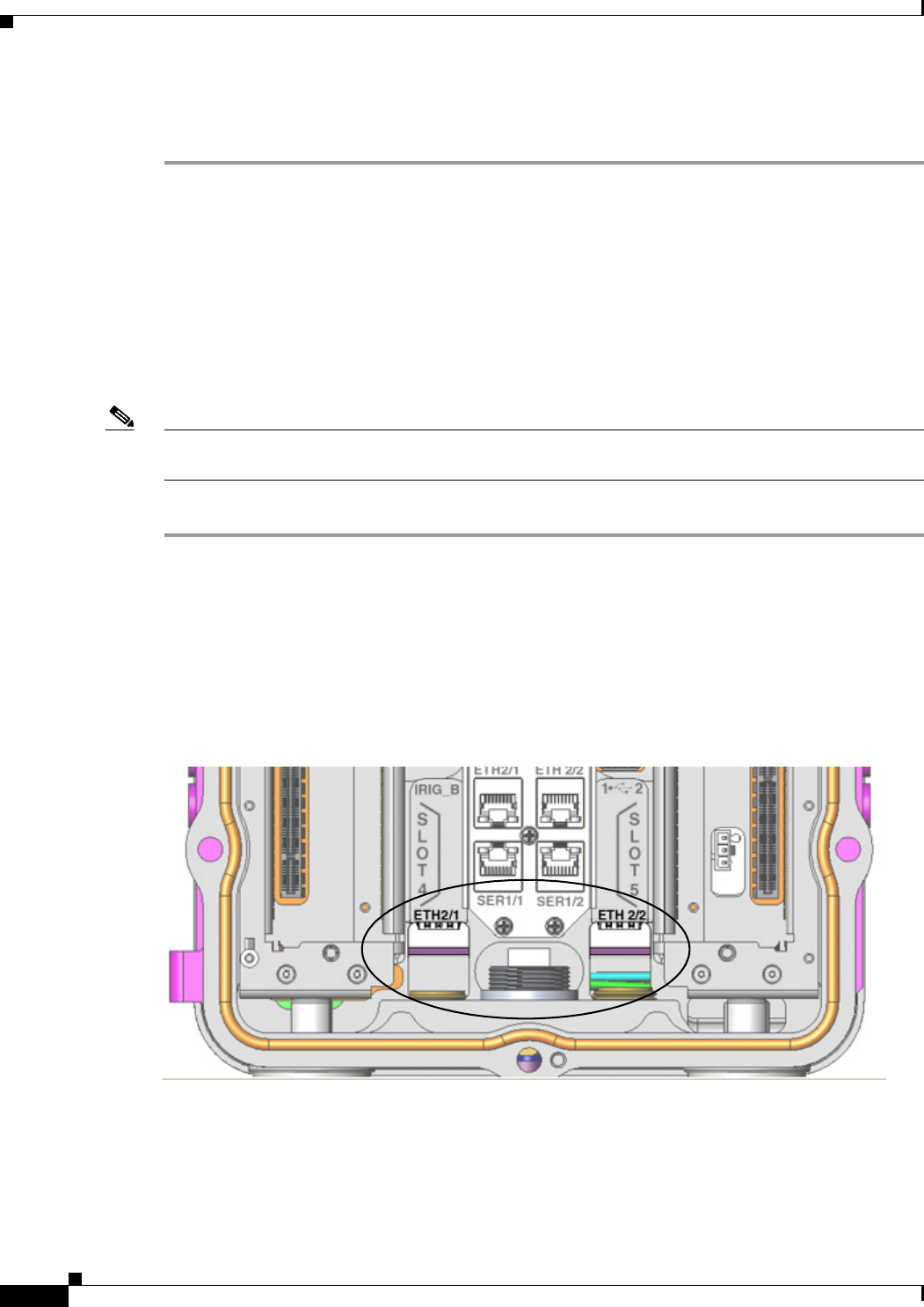
Connecting the Ethernet Ports
About
The router features four Fast Ethernet (FE) ports and two Gigabit Ethernet (GE) ports for connecting the
router to an Ethernet network through a hub or switch (Figure 6-17).
Connecting
• See Figure 6-17 for the Ethernet port labels.
• You can connect SFP modules to these ports while the router is operating normally.
• One or two Ethernet cables are typically provided with the router. Additional cables and transceivers
can be ordered from Cisco. For ordering information, contact customer service.
• When the Ethernet ports, you must use cable glands and thread cables through the chassis cable ports
on the router. See External Connections and Chassis Cable Ports, page 6-10 for more information
• The GE ports (ETH 2/1 and ETH 2/2) have identical labels to the SFP ports because the SFP ports
share physical ports with the GE ports. For detailed information about how to use these ports, see
Hot Swapping SFP Modules, page 2-25, in the chapter Router Hardware Description, page 2-1.
Warning
Do not work on the system or connect or disconnect cables during periods of lightning activity.
Statement 1001
Related Information
Router Hardware Description includes detailed information about these ports, including:
• Specifications
• Standards
• Link to pinout information
DEC. 2011—EFT REVIEW DRAFT—CISCO CONFIDENTIAL
6-22
Cisco 1240 Connected Grid Router Hardware Installation Guide
OL-26223-01
Chapter 6 Installing the Router
Additional Router Connections
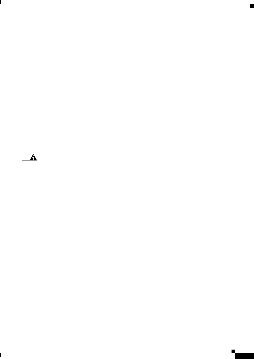
Figure 6-17 Ethernet Port Locations
Connecting the Alarm Port
Note Currently not supported. This hardware feature will be supported in a future software release.
About
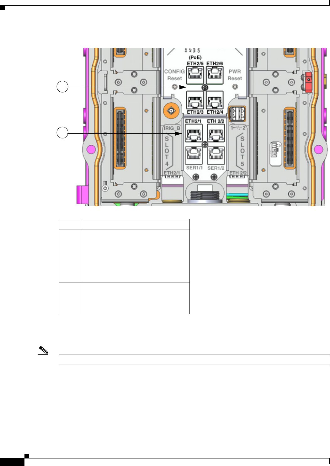
The alarm port provides data about fatal or severe errors that can cause the system software to crash.
The alarm port is connected to a normally closed solid state relay. Cisco IOS writes to a hardware port
and the relay contact opens. If the system enters into a ROM monitor (ROMmon) or watchdog reset state,
the relay contacts close. The closing contacts alert the alarm annunciator or monitor that a Cisco IOS
crash has occurred.
Item Description
1Fast Ethernet ports (4):
• ETH 2/3
• ETH 2/4
• ETH 2/5
• ETH 2/6
2Gigabit Ethernet Combo ports (2):
• ETH 2/1
• ETH 2/2
1
2
DEC. 2011—EFT REVIEW DRAFT—CISCO CONFIDENTIAL
6-23
Cisco 1240 Connected Grid Router Hardware Installation Guide
OL-26223-01
Chapter 6 Installing the Router
Additional Router Connections
If interfaces fail or other non-fatal errors occur, the alarm port does not respond. Continue to use SNMP
to manage these types of errors.
Connecting
• You can connect this port while the router is operating normally.
• If you use an alarm system on your network, connect the alarm port to an alarm system, using an
alarm cable that you provide.
• When connecting this port to an external alarm system, you must use cable glands and thread cables
through the chassis cable ports on the router. See External Connections and Chassis Cable Ports,
page 6-10 for more information
Related Information
Router Hardware Description includes detailed information about this port, including:
• Specifications
• Location on the router
• Link to pinout information
Figure 6-18 Alarm Port Location
Connecting the IRIG-B Port
Note Currently not supported. This hardware feature will be supported in a future software release.
About
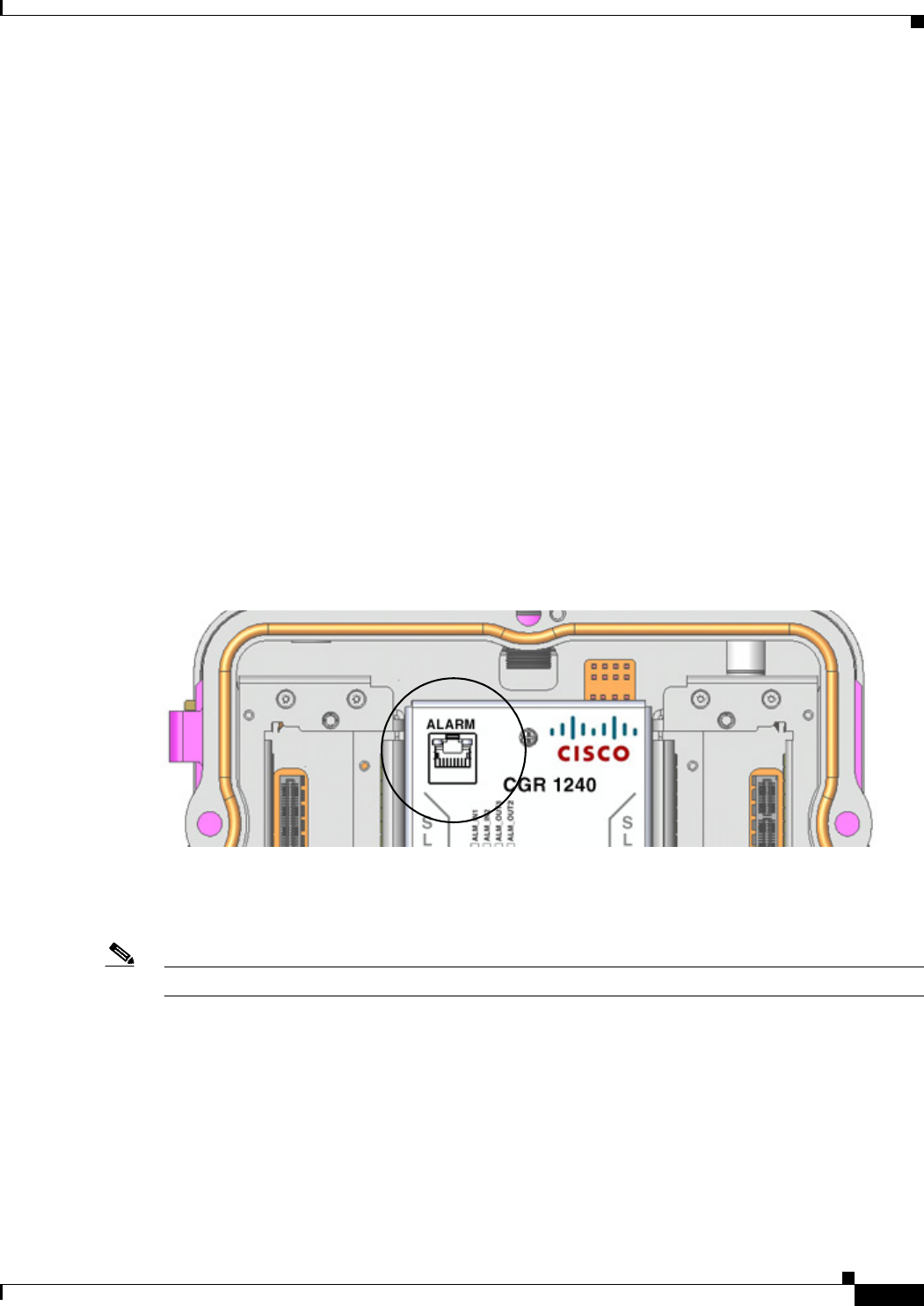
The IRIG-B port provides precise time data. The source of the time is the GPS to which the router is
connected. This port provides time output only.
Connecting
• You can connect this port while the router is operating normally.
DEC. 2011—EFT REVIEW DRAFT—CISCO CONFIDENTIAL
6-24
Cisco 1240 Connected Grid Router Hardware Installation Guide
OL-26223-01
Chapter 6 Installing the Router
Installing Modules and Antennas
• Connect the IRIG port to an external device that requires precise time-of-the day information for
synchronizing data with time.
• You must provide the device and the cable for this connection.
• When connecting this port to an external device, you must use cable glands and thread cables
through the chassis cable ports on the router. See External Connections and Chassis Cable Ports,
page 6-10 for more information
Related Information
Router Hardware Description includes detailed information about this port, including:
• Supported serial time code formats
• Location on the router
Figure 6-19 IRIG-B Timing Port
Installing Modules and Antennas
The router supports up to four Cisco Connected Grid modules. Each module requires one or two
antennas, which are installed on or near the router. See these documents for detailed information about
installing Connected Grid modules and antennas:
URLs for these documents are TBD
• Connected Grid Antenna Installation Guide
• Cisco Connected Grid Cellular 3G Module for CGR1000 Series Installation and Configuration
Guide
• Cisco Connected Grid WiMAX Module for CGR1000 Series Installation and Configuration Guide
• Cisco Connected Grid WPAN Module for CGR1000 Series Installation and Configuration Guide

CHAPTER
DEC. 2011—EFT REVIEW DRAFT—CISCO CONFIDENTIAL
7-1
Cisco 1240 Connected Grid Router Hardware Installation Guide
OL-26223-01
7
About Router Connected Grid Modules
The Cisco 1240 Connected Grid Router supports up to four Cisco Connected Grid modules to enable
wireless connections from the router to field devices, such as smart meters, and from the router to the
utility or data management center.
Module Installation and Configuration Information
Depending on the configuration, your router could arrive in the shipping container with all required
modules already installed.
For instructions on how to install, replace, and configure the modules, see the corresponding installation
and configuration guide for each Cisco Connected Grid module.
URLs for these documents TBD.
Table 7-1 Connected Grid Modules for CGR 1000 Series Routers Documentation
Connected Grid Module Related Documentation
Cisco Connected Grid Modules for
CGR 1000 Series – WiMax
Cisco Connected Grid WiMAX Module for CGR 1000
Series Installation and Configuration Guide
Cisco Connected Grid Modules for
CGR 1000 Series – Cellular 3G
Cisco Connected Grid Cellular 3G Module for CGR 1000
Series Installation and Configuration Guide
Cisco Connected Grid Modules for
CGR 1000 Series – WPAN
Cisco Connected Grid WPAN Module for CGR1000 Series
Installation and Configuration Guide

DEC. 2011—EFT REVIEW DRAFT—CISCO CONFIDENTIAL
7-2
Cisco 1240 Connected Grid Router Hardware Installation Guide
OL-26223-01
Chapter 7 About Router Connected Grid Modules
Module Installation and Configuration Information

CHAPTER
DEC. 2011—EFT REVIEW DRAFT—CISCO CONFIDENTIAL
8-1
Cisco 1240 Connected Grid Router Hardware Installation Guide
OL-26223-01
8
About Router Antennas
This chapter contains detailed information about the antennas for the
Cisco 1240 Connected Grid Router. Router antennas provide connectivity to the router internal GPS and
access point, as well as to any Cisco Connected Grid modules installed in the router.
This chapter contains the following sections:
• Installing or Replacing Antennas, page 8-1
• Antennas Overview, page 8-2
• Antenna Ports, page 8-5
• Safety Information, page 8-7
• Antenna Technical Specifications, page 8-7
Installing or Replacing Antennas
Depending on the configuration you specified, the router could arrive in the shipping container with all
required antennas already installed and connected to the corresponding Cisco Connected Grid modules,
also installed in the router.
However, you might need to install an antenna when:
• You purchase a module separately from the router. The antenna is included with the module, and
must be installed on the router to complete the module installation.
• You purchase an antenna separately to replace a faulty or damaged antenna.
Procedures and safety information required to install or replace antennas are in the Connected Grid
Antennas Installation Guide:
http://www.cisco.com/en/US/docs/routers/connectedgrid/antennas/installing/cg_antenna_install_guide
.html
Lightning Arrestor
Every external Connected Grid antenna that is installed on the router requires a lightning arrestor.
External antennas are any antennas that are connected to the router antenna port N-connector with a
cable.
You can order lightning arrestors from Cisco using Product ID (PID): CGR-LA-N-N.

DEC. 2011—EFT REVIEW DRAFT—CISCO CONFIDENTIAL
8-2
Cisco 1240 Connected Grid Router Hardware Installation Guide
OL-26223-01
Chapter 8 About Router Antennas
Antennas Overview
For information about the lightning arrestor and how to install it, see the Connected Grid Antennas
Installation Guide:
http://www.cisco.com/en/US/docs/routers/connectedgrid/antennas/installing/cg_antenna_install_guide
.html
Cisco Connected Grid Modules
See the installation and configuration guide for each Connected Grid module for instructions on how to
install or replace modules in the router:
Module Documentation - Cisco.com URL TBD
Antennas Overview
This section is an overview of the type of antennas used with the router.
Fixed Antennas
The router ships with two fixed antennas:
• GPS Antenna, page 8-2
• WiFi Antenna, page 8-3
Module Antennas
The router also supports up to seven Connected Grid Module Antennas, page 8-4.
GPS Antenna
The router ships with one outdoor GPS antenna already installed and connected internally to the router
on-board GPS Module. The GPS is used to identify the router location after the router is installed and is
in use.
The GPS antenna is not a field-replaceable component.
• For detailed technical information about the GPS antenna, see the section GPS Antenna
Specifications, page 8-8.
• For information about the GPS status LED, located inside the router chassis, see the chapter Router
LED Locations and States.
• For more information about the GPS Module, see the chapter Router Hardware Description.
DEC. 2011—EFT REVIEW DRAFT—CISCO CONFIDENTIAL
8-3
Cisco 1240 Connected Grid Router Hardware Installation Guide
OL-26223-01
Chapter 8 About Router Antennas
Antennas Overview
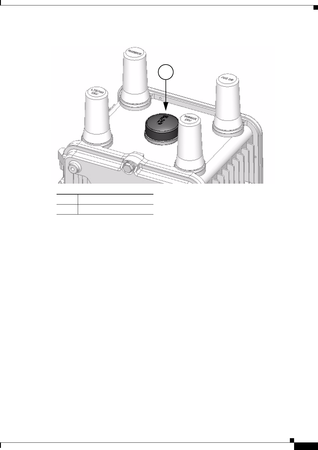
Figure 8-1 GPS Antenna—Cisco CGR 1240 Router
WiFi Antenna
The router ships with one omni-directional, monopole WiFi antenna already installed and connected
internally to the router internal short-range access point. The router WiFi link enables users to connect
to the router from anywhere within WiFi range. For example, a technician can check the status of the
router from the ground (instead of having to physically open the router on its poletop installation) by
remotely connecting to the router over the WiFi link.
The WiFi antenna is a field replaceable component. The Cisco Product ID (PID) for the Wifi antenna is
ANT-MP-INT-OUT-M.
• For detailed technical information about the WiFi antenna, see the section WiFi Antenna
Specifications, page 8-9.
• For information about the WiFi status LED, see the chapter Router LED Locations and States.
• For more information about the Short-Range Access Point, which provides the WiFi connection to
the router, see the chapter Router Hardware Description.
Item Description
1GPS antenna
1
DEC. 2011—EFT REVIEW DRAFT—CISCO CONFIDENTIAL
8-4
Cisco 1240 Connected Grid Router Hardware Installation Guide
OL-26223-01
Chapter 8 About Router Antennas
Antennas Overview
Figure 8-2 WiFi Antenna—Cisco CGR 1240 Router
Connected Grid Module Antennas
In addition to the two fixed antennas (GPS and WiFi), the router supports up to seven additional
antennas, which provide connectivity to the Connected Grid modules installed in the router. Each
module requires one or two antennas, which are mounted on the exterior of the router and connected
through chassis antenna ports to the module installed inside the router.
The router supports up to four Cisco Connected Grid modules. Each module requires one antenna or two
antennas (one main antenna and one diversity antenna). Diversity antennas improve the quality and
reliability of the wireless connection. Because they are placed in different locations on the router, main
and diversity antennas detect different amounts of interference. The router uses the antenna with the
least interference to obtain the best signal.
The total number of antennas installed on the router depends on:
• Number of modules installed in the router.
• Module types that are installed in the router
For detailed information about the Connected Grid module antennas, see the Connected Grid Antennas
Installation Guide:
http://www.cisco.com/en/US/docs/routers/connectedgrid/antennas/installing/cg_antenna_install_guide
.html
Item Description
1WiFi antenna location
DEC. 2011—EFT REVIEW DRAFT—CISCO CONFIDENTIAL
8-5
Cisco 1240 Connected Grid Router Hardware Installation Guide
OL-26223-01
Chapter 8 About Router Antennas
Antenna Ports
Antenna Ports
This section describes the antenna ports, and includes the following topics:
• Unused Antenna Ports, page 8-5
• Antenna Port Numbering, page 8-5
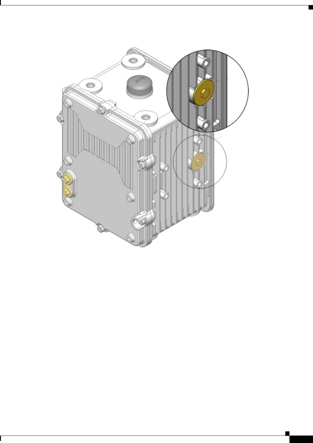
Unused Antenna Ports
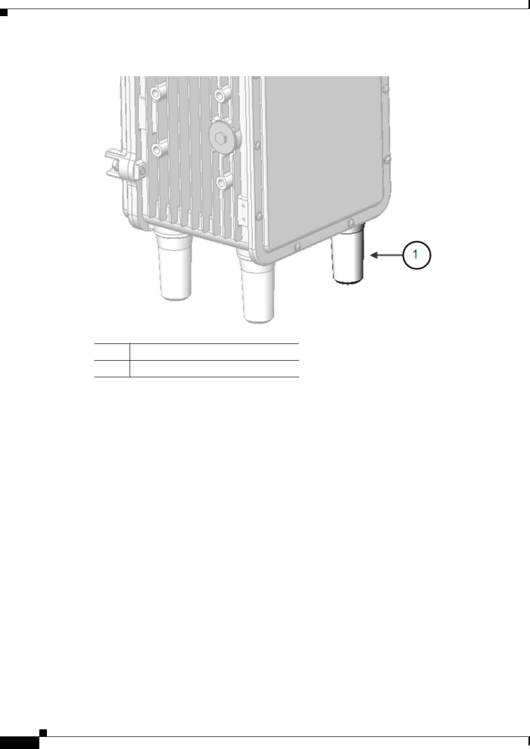
Liquid-tight, female N-connectors are installed in any unused antenna ports. The N-connector protects
the router interior from environmental elements including water, heat, cold, and dust. The N-connectors
are installed in unused antenna ports before the router is shipped.
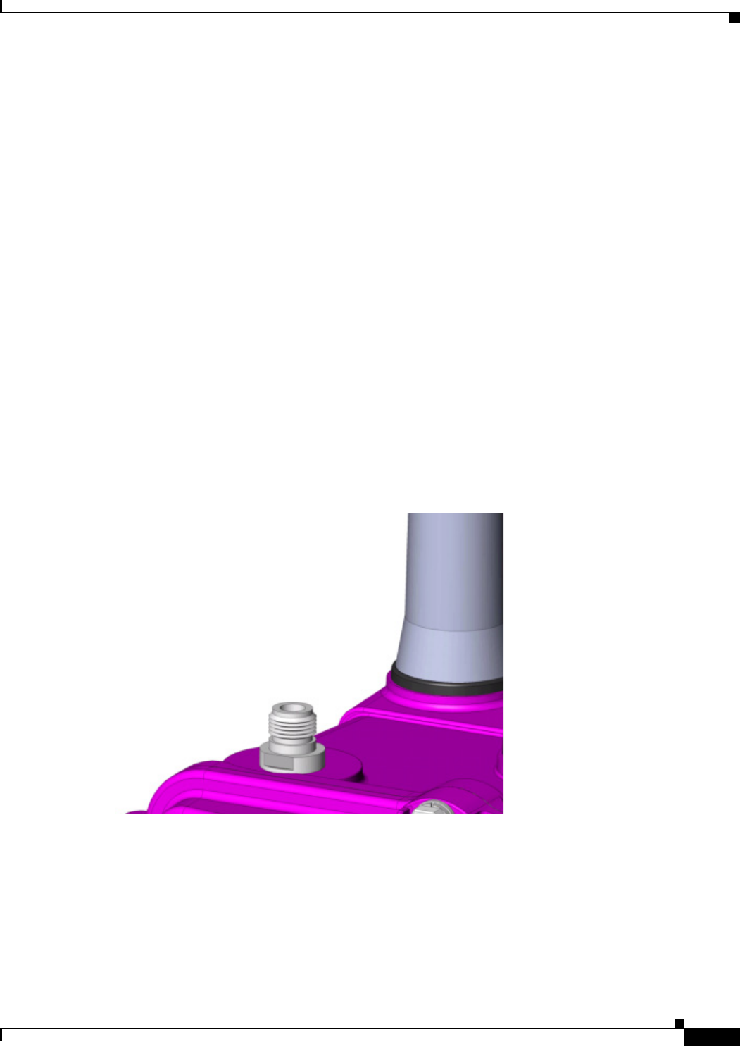
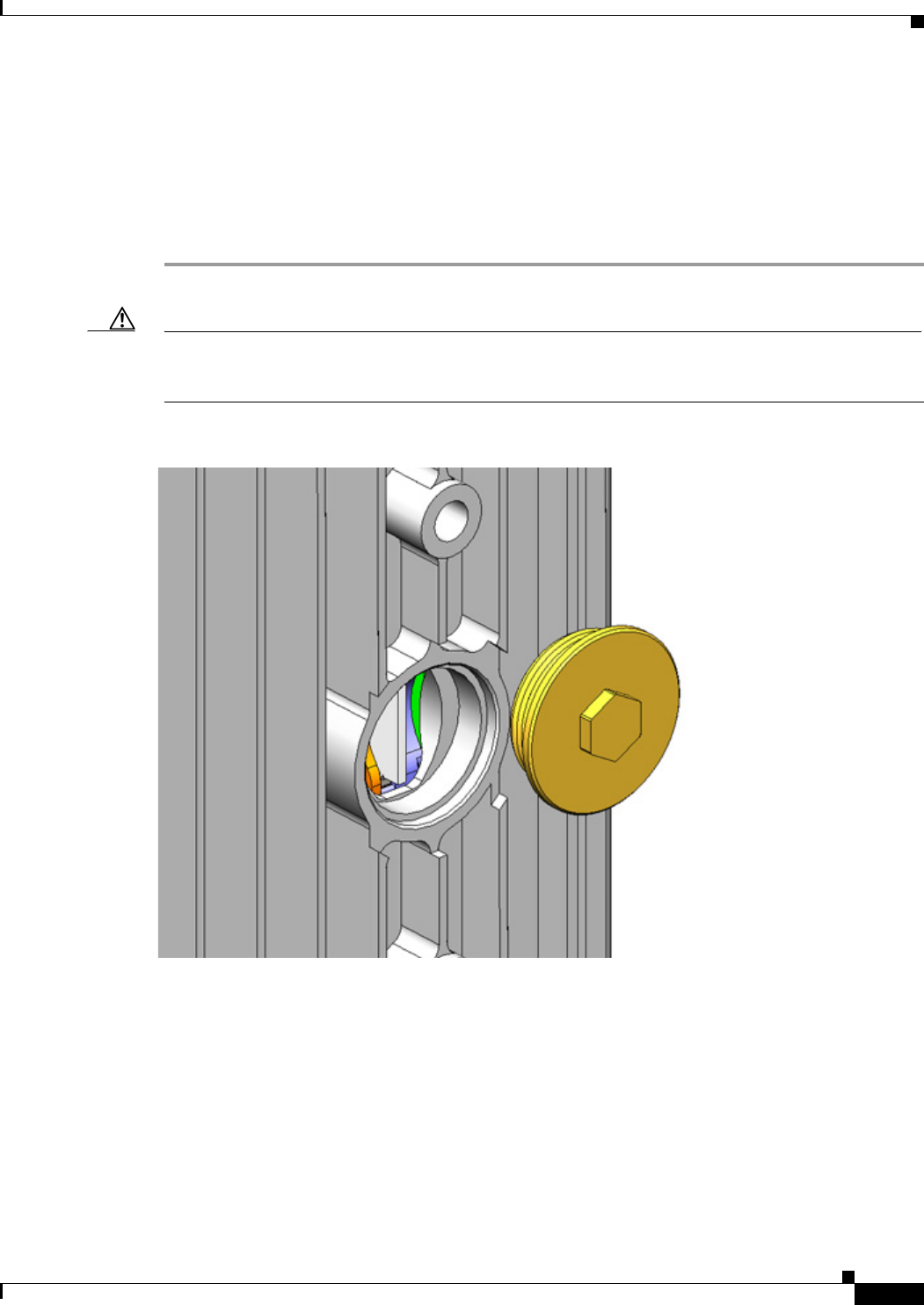
When you install or replace an antenna in a port with an N-connector:
• Chassis-mounted antennas—Remove the N-connector before installing a chassis-mounted antenna.
• External antennas—Connect the supported Cisco lightning arrestor to the N-connector, then connect
the antenna cable to the lightning arrestor.
For detailed instructions for installing antennas, Connected Grid Antennas Installation Guide:
http://www.cisco.com/en/US/docs/routers/connectedgrid/antennas/installing/cg_antenna_install_guide
.html
Figure 8-3 N-Connector Installed in Unused Antenna Port
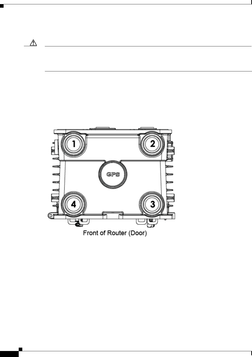
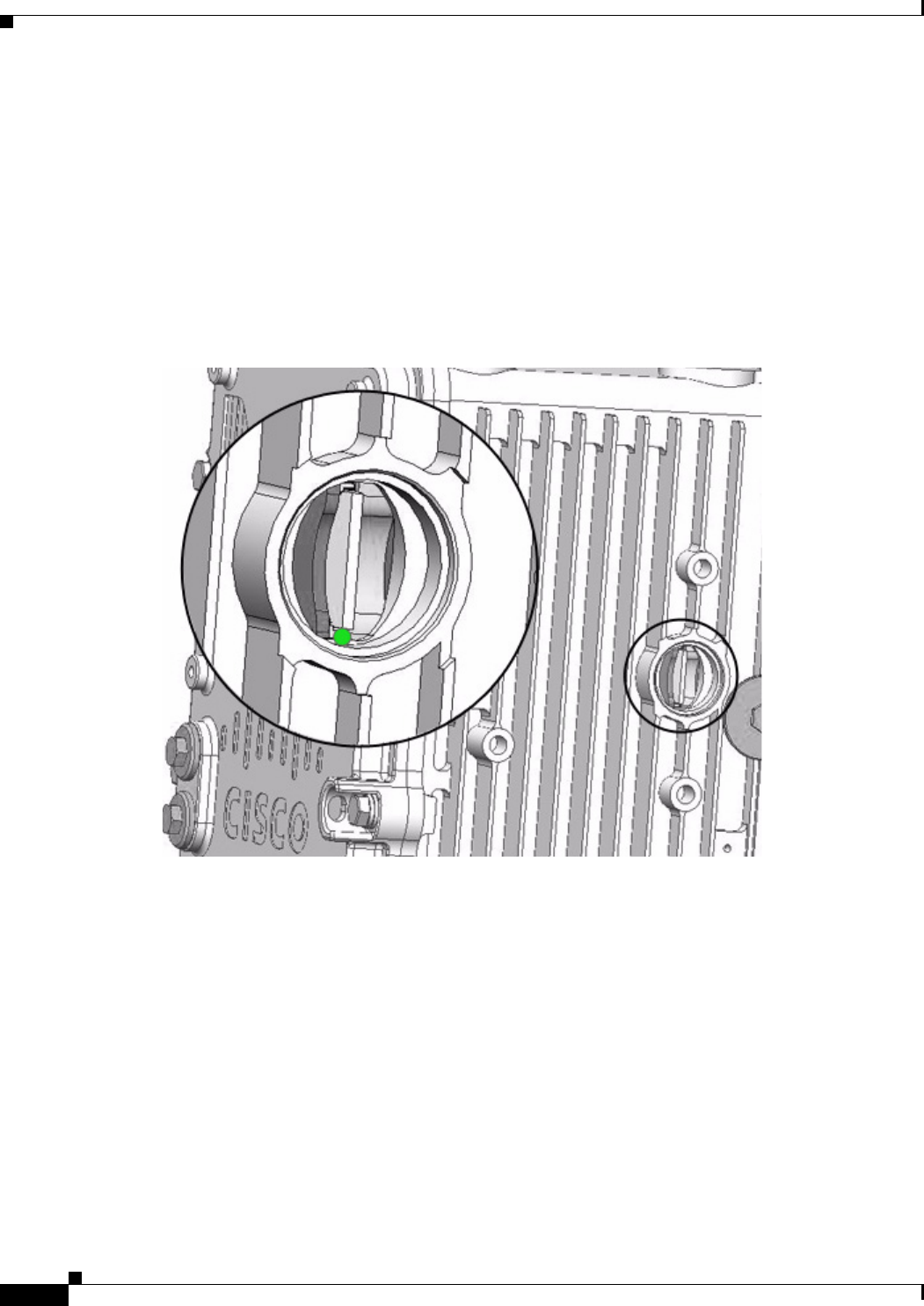
Antenna Port Numbering
This section illustrates the antenna port locations on the router. Each antenna port is numbered. The
antenna port numbers should be referenced by installers, support technicians, and other end users when
installing, replacing, or troubleshooting the antennas.
DEC. 2011—EFT REVIEW DRAFT—CISCO CONFIDENTIAL
8-6
Cisco 1240 Connected Grid Router Hardware Installation Guide
OL-26223-01
Chapter 8 About Router Antennas
Antenna Ports
Antenna Installation Location
Caution Supported Connected Grid antennas can be installed in any of the router antenna ports, however Cisco
recommends that antennas be installed in the locations recommended in the antenna installation guide.
Installing antennas in the recommend locations optimizes ease of installation, antenna performance. and
antenna cable management.
The recommended location for each antenna depends on several factors, including:
• The type and number of Connected Grid modules installed in the router
• The type and number of antennas required to support the installed modules
The procedures in the antenna installation guide refer to the port numbers illustrated in this section.
Figure 8-4 Top of Router—Antenna Port Numbering
DEC. 2011—EFT REVIEW DRAFT—CISCO CONFIDENTIAL
8-7
Cisco 1240 Connected Grid Router Hardware Installation Guide
OL-26223-01
Chapter 8 About Router Antennas
Safety Information
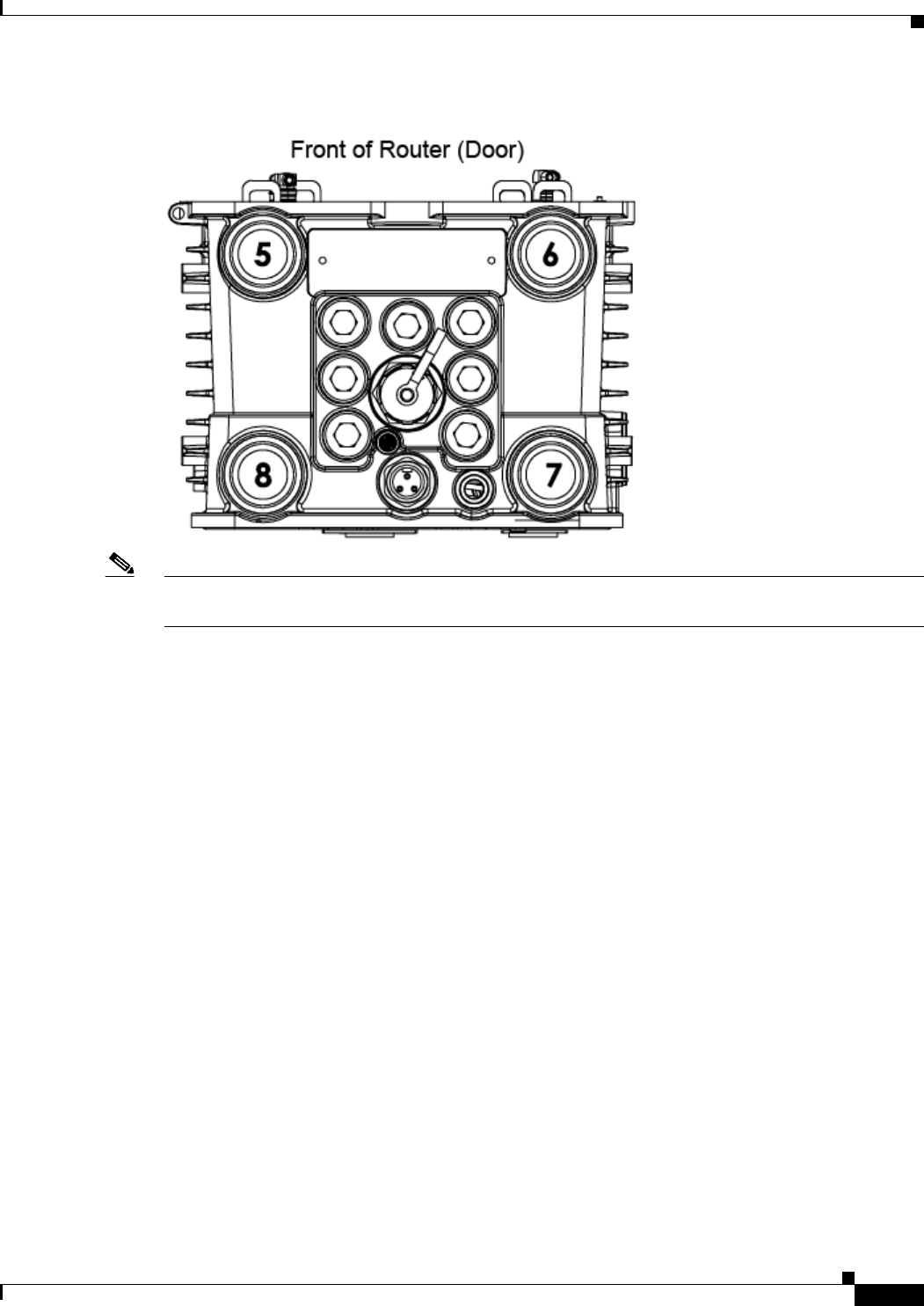
Figure 8-5 Bottom of Router—Antenna Port Numbering
Note The router integrated WiFi Antenna is always installed in port 8, and should not be removed or replaced
with another antenna model.
Safety Information
Read the information in the antenna installation guide before installing or replacing antennas.
Antenna Technical Specifications
This section lists the technical information for the GPS and WiFi antennas:
• GPS Antenna Specifications, page 8-8
• WiFi Antenna Specifications, page 8-9
For specifications for Connected Grid module antennas, see the Connected Grid Anennas Installation
Guide:
http://www.cisco.com/en/US/docs/routers/connectedgrid/antennas/installing/cg_antenna_install_guide
.html
DEC. 2011—EFT REVIEW DRAFT—CISCO CONFIDENTIAL
8-8
Cisco 1240 Connected Grid Router Hardware Installation Guide
OL-26223-01
Chapter 8 About Router Antennas
Antenna Technical Specifications
GPS Antenna Specifications
Specification GPS Antenna
Type Active GPS, chassis mounted
Frequency 1575.42 MHz
Height 22.1 mm
Base diameter 50 mm
Maximum gain (dBi) 5
Polarization RHCP
Coaxial cable length 10 in. (25.4 cm)
Coaxial cable type 50 ohm, double-shielded
Connector SMA-male
Environment Outdoor
Temperature range, operational -40 to 185° F (-40 to 85° C)
Temperature range, storage -40 to 185° F (-40 to 85° C)
DEC. 2011—EFT REVIEW DRAFT—CISCO CONFIDENTIAL
8-9
Cisco 1240 Connected Grid Router Hardware Installation Guide
OL-26223-01
Chapter 8 About Router Antennas
Antenna Technical Specifications
WiFi Antenna Specifications
Specification Wife Antenna
Type Monopole
Environment Outdoor
Height 3.2 in. (8.13 cm)
Width (maximum, at base) 1.75 in. (4.45 cm)
Operating frequency range 806-960 MHz
1710-2170 MHz
Characteristic impedance 50 ohm
VSWR Nominal (Maximum)
806 - 960 MHz (2.5:1)
1710 - 2170 MHz (2.3:1)
2300 - 2700 MHz (2.2:1)
Peak gain Nominal (Maximum)
806-960 MHz (2.5 dBi +/- 1.0 dB)
1710-2170 MHz (1.0 dBi +/- 1.0 dB)
2300-2500 MHz (1.0 dBi +/- 1.0 dB)
2500-2700 MHz (2.5 dBi +/- 1.2 dB)
Polarization Linear
Vertical
Coaxial cable length 14.5 in. (5.7 cm)
Coaxial cable type LMR195 double-shielded
Connector Right angle QMA-male
Temperature range, operational -40 to 185° F (-40 to 85° C)
Temperature range, storage -40 to 185° F (-40 to 85° C)
Maximum input power 10 W (avg.)
Compliance RoHS

DEC. 2011—EFT REVIEW DRAFT—CISCO CONFIDENTIAL
8-10
Cisco 1240 Connected Grid Router Hardware Installation Guide
OL-26223-01
Chapter 8 About Router Antennas
Antenna Technical Specifications

CHAPTER
DEC. 2011—EFT REVIEW DRAFT—CISCO CONFIDENTIAL
9-1
Cisco 1240 Connected Grid Router Hardware Installation Guide
OL-26223-01
9
Using the SD Flash Memory Module
This chapter describes the Secure Digital (SD) flash memory module (or SD card) that is used with the
Cisco 1240 Connected Grid Router, and includes instructions for installing and removing the SD card.
This chapter contains the following sections:
• SD Card Overview, page 9-1
• Supported SD Cards, page 9-2
• Inserting the SD Card, page 9-3
• SD Card Status, page 9-6
• Related Commands, page 9-7
SD Card Overview
The Cisco 1240 Connected Grid Router features an SD card connector, which supports a single Cisco SD
card. The SD card stores router data and software, including:
• Router operating software
• Running configurations
• Network management software configuration
• Network registration data
• Router firmware
• Billing data
• Outage data
• Event data
SD Card File System
The SD card uses a Linux-based EXT2/3 file system. The router configuration is stored in a binary file
in an invisible partition on the card.
Sharing SD Cards Across Systems
The card cannot be used to configure or operate any system other than the system with which is it
shipped.
DEC. 2011—EFT REVIEW DRAFT—CISCO CONFIDENTIAL
9-2
Cisco 1240 Connected Grid Router Hardware Installation Guide
OL-26223-01
Chapter 9 Using the SD Flash Memory Module
SD Card Overview
Supported SD Cards
Table 9-1 lists the SD cards that can be used with the router.
Note For detailed specifications about the SD flash memory module, refer to Router Hardware Description.
Accessing the SD Card
The SD card is accessed from the router exterior, though the router SD card port, shown in Figure 9-1.
Caution Removing the SD card during normal router operation will cause the router to stop operating. Do not
remove the SD card while the router is operating.
Note When the Cisco mounting bracket is attached the router, the bracket blocks access to the SD card port
slot the router exterior. To access the SD card slot without removing the router from the bracket or any
mounting installation that uses the bracket, refer to the instructions in Mounting the Router.
Table 9-1 Supported SD Flash Modules
Cisco Part Number1
1. At FCS, these internal part numbers must be replaced with customer-facing Product ID (PID)
numbers. (PIDs not available yet in InBiz. November 29, 2011.)
Size
16-3704-01 1 GB
16-3795-01 2 GB
16-3798-01 4 GB
DEC. 2011—EFT REVIEW DRAFT—CISCO CONFIDENTIAL
9-3
Cisco 1240 Connected Grid Router Hardware Installation Guide
OL-26223-01
Chapter 9 Using the SD Flash Memory Module
Inserting the SD Card
Figure 9-1 SD Card Port Location on Router Exterior
Inserting the SD Card
Depending on the configuration, the router could arrive in the shipping container with the SD card
already installed.
However, you might need to install an SD card in the router when:
• You are upgrading router with software or firmware stored on the SD card.
• The router requires an SD card with greater memory capacity.
• You must replace a faulty or damaged SD card.
Online Insertion and Removal (OIR)
The SD card can be installed and removed while the router is operating normally.

DEC. 2011—EFT REVIEW DRAFT—CISCO CONFIDENTIAL
9-4
Cisco 1240 Connected Grid Router Hardware Installation Guide
OL-26223-01
Chapter 9 Using the SD Flash Memory Module
Inserting the SD Card
Safety Warnings
Before performing any of the tasks in this chapter, read the safety warnings in the Installation Safety and
Site Preparation chapter.
Preventing Electrostatic Discharge Damage
SD flash memory modules are sensitive to electrostatic discharge (ESD) damage, which can occur when
electronic cards or components are handled improperly, results in complete or intermittent failures.
To prevent ESD damage, follow these guidelines:
• Always use an ESD wrist or ankle strap and ensure that it makes good skin contact.
• Connect the equipment end of the strap to an unfinished chassis surface.
• Place a removed the memory card on an antistatic surface or in a static shielding bag. If the card will
be returned to the factory, immediately place it in a static shielding bag.
• Avoid contact between the card and clothing. The wrist strap protects the card from ESD voltages
on the body only; ESD voltages on clothing can still cause damage.
• Do not remove the wrist strap until the installation is complete.
Tools You Supply
You must provide a 13-mm box-end wrench or socket set to access the SD card.
Removing and Inserting the SD Card
To install or remove and SD card:
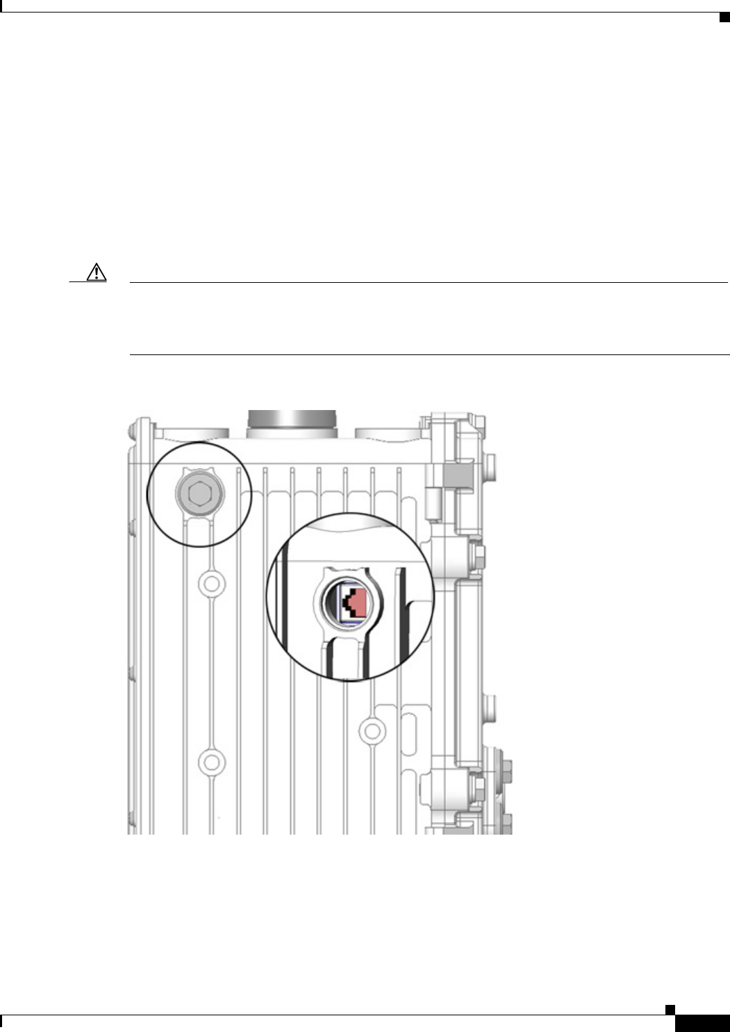
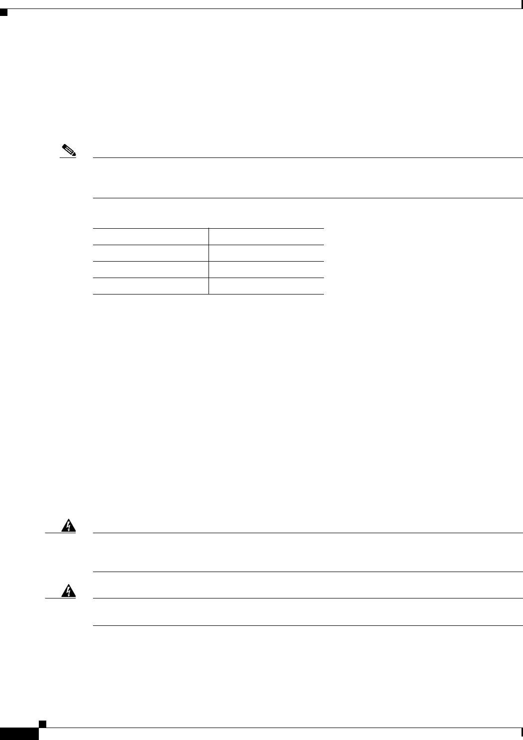
Step 1 Use the wrench to loosen the seal that covers the SD card slot (Figure 9-2).
Step 2 Confirm that the SD card LED (Figure 9-3) displays one of the following states:
• Green—Installed SD card is operating normally.
• Amber blinking—An unsupported card is installed in the router SD card slot.
• Amber flashing—No SD card is installed in the router SD card slot.
Caution Do not replace the SD card if the LED is blinking green. A blinking green state indicates that a data
transfer between the router and the SD card is in progress. Removing the card during a data transfer will
interrupt this process and could damage system data.
Step 3 To remove an SD card from the router:
a. Press the SD card in slightly. The card moves outward so that it projects from the slot.
b. Pull the SD card out of the slot.
c. Place the SD card in an antistatic bag to protect it from static discharge.
DEC. 2011—EFT REVIEW DRAFT—CISCO CONFIDENTIAL
9-5
Cisco 1240 Connected Grid Router Hardware Installation Guide
OL-26223-01
Chapter 9 Using the SD Flash Memory Module
Inserting the SD Card
Step 4 To install an SD card in the router:
a. Insert the SD card by sliding it into the SD card slot, with the connector first and the notched corner
facing up. The card is keyed so that you cannot insert it the wrong way.
b. Ensure that the card is seated in the slot connector and the edge of the card is flush with the edge of
the slot.
Step 5 Replace and tighten the seal that you removed in Step 1, using the wrench you supply.
Caution You must replace and tighten the seal that covers the SD card port when not using the port. If the card
port is not sealed, the router interior could be exposed to environmental elements, such as water, heat,
cold, and dust, that can permanently damage the router.
Figure 9-2 SD Card Slot with SD Card Inserted
DEC. 2011—EFT REVIEW DRAFT—CISCO CONFIDENTIAL
9-6
Cisco 1240 Connected Grid Router Hardware Installation Guide
OL-26223-01
Chapter 9 Using the SD Flash Memory Module
SD Card Status
SD Card Status
You can check the SD card status by viewing the SD Card LED.
SD Card LED
The SD card LED is located directly next to the SD card slot, and is visible when the SD card slot seal
is removed. This section describes the LED states and descriptions.
Figure 9-3 SD Card LED Location

DEC. 2011—EFT REVIEW DRAFT—CISCO CONFIDENTIAL
9-7
Cisco 1240 Connected Grid Router Hardware Installation Guide
OL-26223-01
Chapter 9 Using the SD Flash Memory Module
Related Commands
Figure 9-4 SD Flash Memory Module (SD0) LED States
Related Commands
Use the copy running-config startup-config command to save the router current software configuration
to the SD card:
cgr1240# copy running-config startup-config
[########################################] 100%
Copy complete, now saving to disk (please wait)...
Label
Description Color and State Description
SD0
SD flash card status
Green solid SD flash card is installed and operating normally.
Green blinking A data transfer between the router and the SD card is in
progress.
Amber solid • An error occurred when the router accessed the SD
flash card.
• The router could not find a system software image.
Amber blinking An unsupported SD card is installed in the slot.
Amber flashing No SD card is installed in slot.

DEC. 2011—EFT REVIEW DRAFT—CISCO CONFIDENTIAL
9-8
Cisco 1240 Connected Grid Router Hardware Installation Guide
OL-26223-01
Chapter 9 Using the SD Flash Memory Module
Related Commands

CHAPTER
DEC. 2011—EFT REVIEW DRAFT—CISCO CONFIDENTIAL
10-1
Cisco 1240 Connected Grid Router Hardware Installation Guide
OL-26223-01
10
Installing Battery Backup Units
The Cisco 1240 Connected Grid Router supports up to three installed battery backup units, which
provide power to the router if the AC power fails. This chapter describes the Cisco Connected Grid
Battery Backup Unit features and how to install the battery backup unit in the router.
This chapter includes the following sections:
• Battery Backup Unit (BBU) Description, page 10-1
• BBU Components, page 10-5
• Battery Backup Unit LED, page 10-14
• BBU Technical Specifications, page 10-16
Battery Backup Unit (BBU) Description
The battery backup unit (BBU) provides the router with an emergency power source if the AC power
source is unavailable. The router supports up to three installed BBU units at one time. The total amount
of time that the installed BBUs can supply power to the router depends on how many BBUs are installed
in the router. The BBU can be installed in the router while the router is powered on and operating
normally.
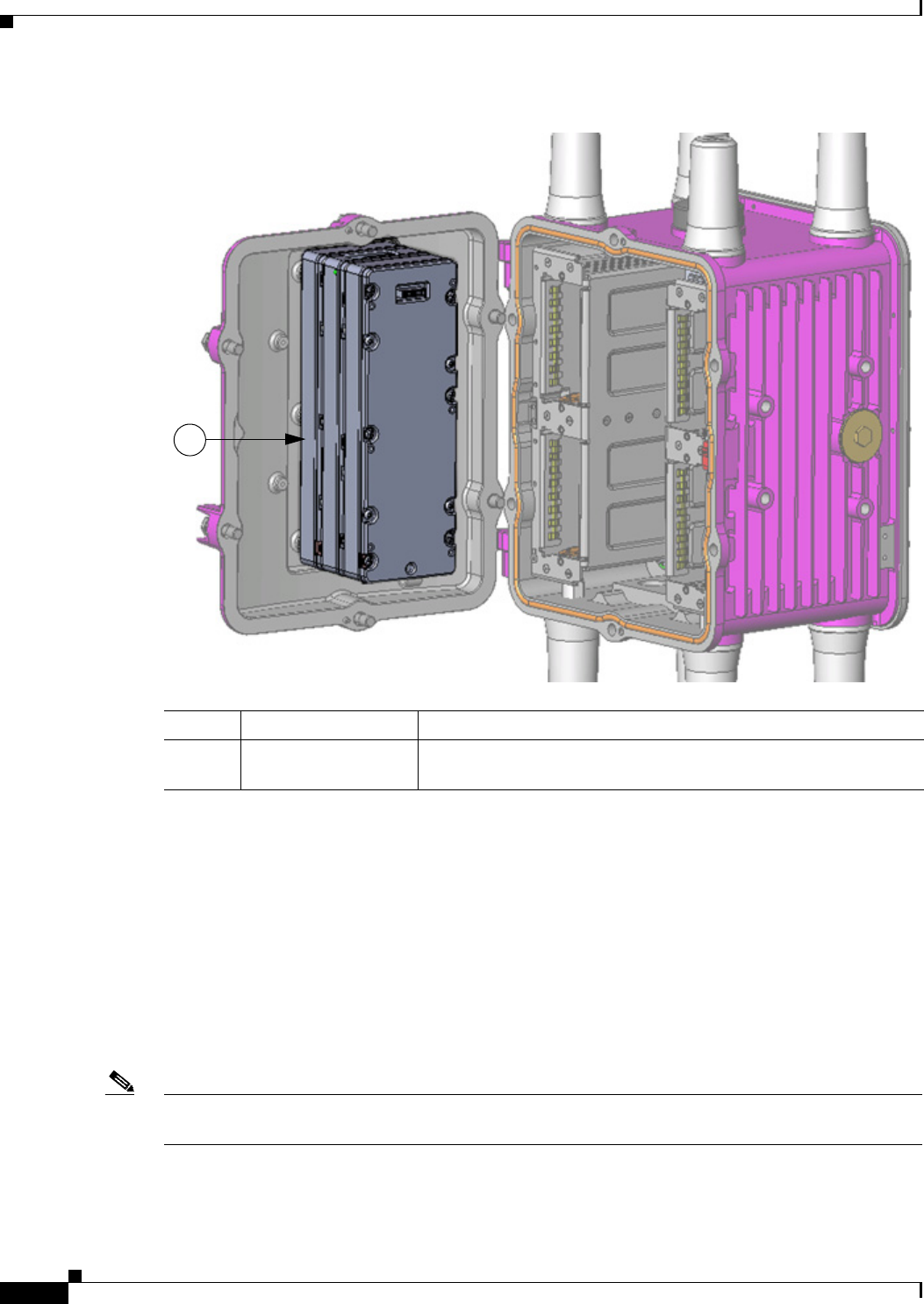
The BBU is mounted on the router door interior (Figure 10-1). The BBU internal components include
battery cells, a primary protection circuit, a fuel gauge, and a charger. For detailed, illustrated
descriptions of the BBU, see BBU Components, page 10-5.
DEC. 2011—EFT REVIEW DRAFT—CISCO CONFIDENTIAL
10-2
Cisco 1240 Connected Grid Router Hardware Installation Guide
OL-26223-01
Chapter 10 Installing Battery Backup Units
Battery Backup Unit (BBU) Description
Figure 10-1 Battery Backup Units Mounted on Router Door
Enabling the BBU
The BBU is automatically enabled and begins supplying power to the router when the router detects that
power is not being received from the AC power supply. The BBU continues to supply power to the router
until at least one of the following conditions is met:
• The BBU is completely discharged
• AC power to the router is enabled
• The BBU battery cable is disconnected from the router
• The BBU is disabled with the system software (see BBU Technical Specifications, page 10-16)
Note BBU Technical Specifications, page 10-16, contains technical details about the router power path
selection and the conditions that trigger the BBU to begin operating.
Item Cisco Product ID (PID) Description
1CGR-BATT-4AH Battery backup units. The router supports up to three BBUs, as
shown here.
1
NOTE TO WRITER: Same illustration file as for Figure 4-4 (Opening Router Chassis)

DEC. 2011—EFT REVIEW DRAFT—CISCO CONFIDENTIAL
10-3
Cisco 1240 Connected Grid Router Hardware Installation Guide
OL-26223-01
Chapter 10 Installing Battery Backup Units
Battery Backup Unit (BBU) Description
Battery Backup Mode
This section describes impact to the router configuration and operating capabilities when the router
switches from AC power to BBU power.
Event Messages
When the router detects that the power supply has changed from AC power to BBU power, the BBU is
enabled and the following syslog message is sent to the network management system:
Power mode changed to battery mode.
Router Configuration
The router software configuration is not impacted when the router switches from AC power to BBU
power.
Ethernet Switch and Connected Grid Module Operation
By default, the Ethernet switch module (module 2) and any Connected Grid modules installed in slots
3, 4, 5, and 6 continue to operate normally when the router switches from AC power to BBU power.
You can configure the router to automatically power off specific modules when the router switches to
BBU power. See Related Commands, page 10-15 for information on how to use the poweroff module
number backup-battery command to configure the modules (including the Ethernet switch) that shut
down when the router switches to BBU power.
Router Interface Operation
To conserve power, the router will power off some interfaces when AC power is not available, and the
router is being powered by the BBU. When these interfaces are in power off mode, you cannot configure
them with the system software; however, you can display information about each interface using the
show commands for the interface. These include:
• show running config
• show hardware
• show interface
The following interfaces and router components switch to power off mode when the BBU is supplying
power to the router:
• Both SFP interfaces
• Both external USB ports
• Both serial (S232/485) ports
• IRIG-B port
BBU Charging and Discharging
This section will discuss BBU charging/discharging cycles. Behavior is TBD. 5-October-11. Per
George Madden on Jan 9, check with software team.
DEC. 2011—EFT REVIEW DRAFT—CISCO CONFIDENTIAL
10-4
Cisco 1240 Connected Grid Router Hardware Installation Guide
OL-26223-01
Chapter 10 Installing Battery Backup Units
Preparing to Install the BBU
BBU Capacity
The router supports up to three BBUs at one time. You should install as many BBUs as needed, up to
three, to meet your emergency power requirements.
If all installed batteries fully discharge while providing backup power to the router, the router will send
a dying gasp message and then shut down.
Note The BBU provides power durations shown in Table 10-1 when the router is in a reduced power
consumption state, as described in Router Interface Operation, page 10-3. The durations in Table 10-1
are valid for 5 years.
Preparing to Install the BBU
Tools You Supply
You must provide a #1 Phillips screwdriver to install the BBU.
Safety Information for Installation
Safety Warnings
Before performing any of the tasks in this chapter, read the safety warnings in the Installation Safety and
Site Preparation chapter.
Warning
There is the danger of explosion if the battery is replaced incorrectly. Replace the battery only with
the same or equivalent type recommended by the manufacturer. Dispose of used batteries according
to the manufacturer's instructions.
Statement 1015
Warning
Only trained and qualified personnel should be allowed to install, replace, or service this equipment.
Statement 1030
Preventing Electrostatic Discharge Damage
The BBUs are sensitive to electrostatic discharge (ESD) damage which can occur when electronic cards
or components are handled improperly, and can result in complete or intermittent failures.
Table 10-1 Cisco Connected Grid Battery Backup Unit Model Number
Backup Power (Hours) Number of BBUs
4 1
8 2
12 3

DEC. 2011—EFT REVIEW DRAFT—CISCO CONFIDENTIAL
10-5
Cisco 1240 Connected Grid Router Hardware Installation Guide
OL-26223-01
Chapter 10 Installing Battery Backup Units
Preparing to Install the BBU
To prevent ESD damage, follow these guidelines:
• Always use an ESD wrist or ankle strap and ensure that it makes good skin contact.
• Connect the equipment end of the strap to an unfinished chassis surface.
• Place the BBU on an antistatic surface or in a static shielding bag. If the BBU will be returned to
the factory, immediately place it in a static shielding bag.
• Avoid contact between the battery and clothing. The wrist strap protects the battery from ESD
voltages on the body only; ESD voltages on clothing can still cause damage.
• Do not remove the wrist strap until the installation is complete.
BBU Components
This section illustrates and describes the BBU components you should be familiar with when installing
the BBU.
Note For technical specifications of the components described in this section, see BBU Technical
Specifications, page 10-16.
DEC. 2011—EFT REVIEW DRAFT—CISCO CONFIDENTIAL
10-6
Cisco 1240 Connected Grid Router Hardware Installation Guide
OL-26223-01
Chapter 10 Installing Battery Backup Units
Preparing to Install the BBU
Battery-to-Battery Connectors
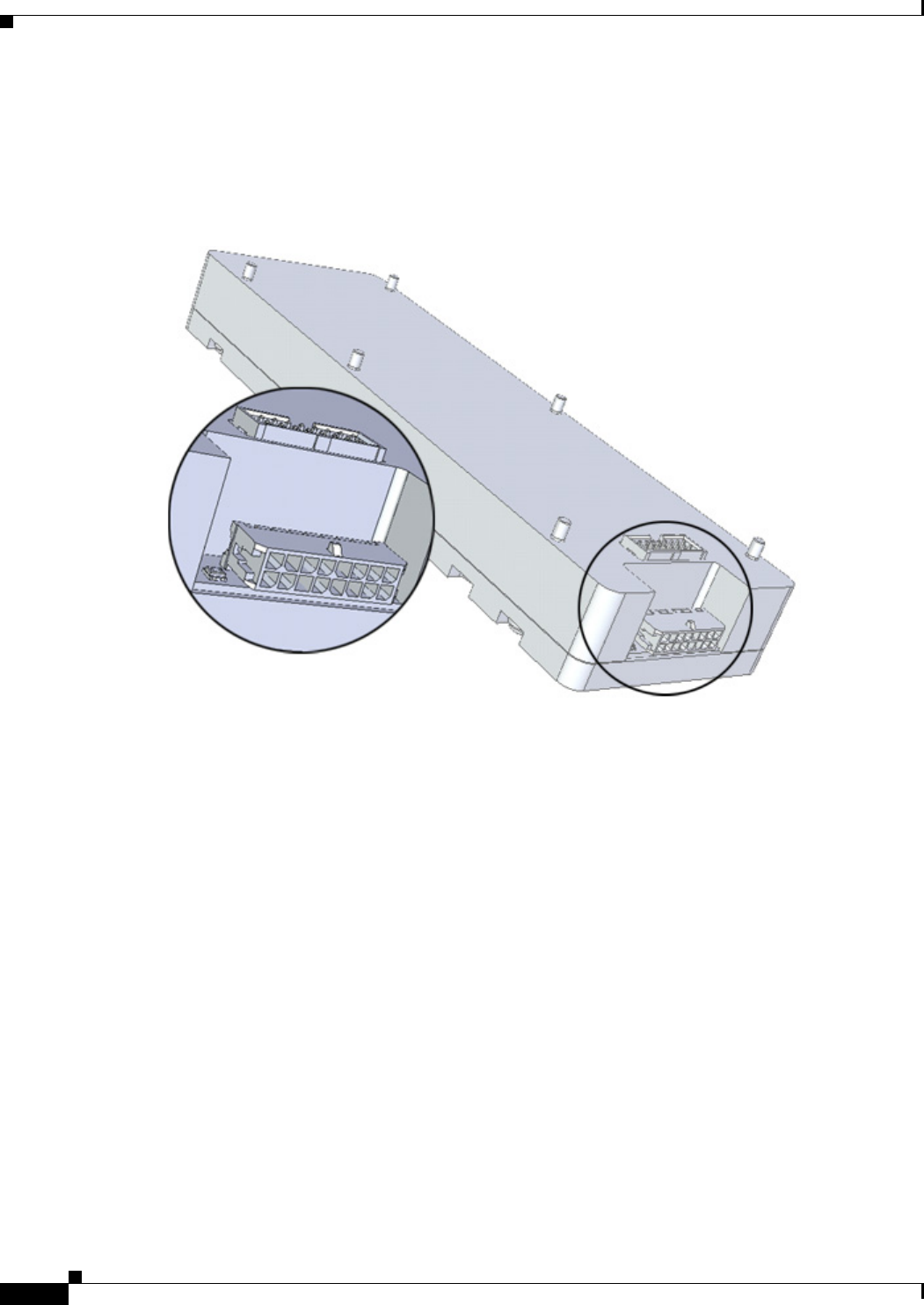
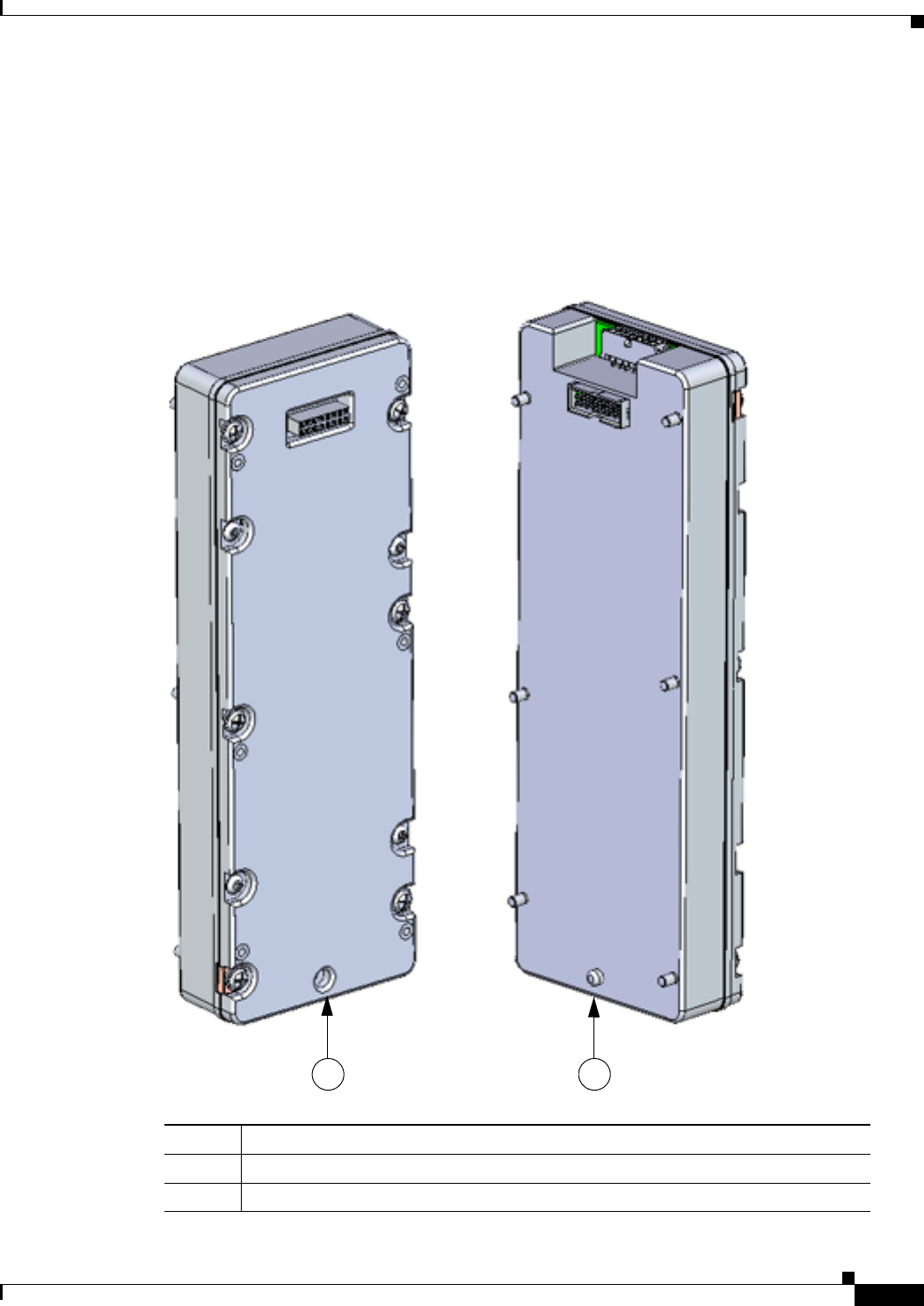
Figure 10-2 Front of Battery Backup Unit
Item Description
1Captive screws (6) for installing the BBU directly to the router door or to another
BBU already installed on the router door.
2Battery-to-battery connector, female. The BBU features two battery-to-battery
connectors: one male and one female, which are used to connect batteries together
when two or more batteries are installed in one router.
3Threaded connectors, to attach an additional BBU (6)
1 2
3
DEC. 2011—EFT REVIEW DRAFT—CISCO CONFIDENTIAL
10-7
Cisco 1240 Connected Grid Router Hardware Installation Guide
OL-26223-01
Chapter 10 Installing Battery Backup Units
Preparing to Install the BBU
Figure 10-3 Rear of Battery Backup Unit
Item Description
1Battery-to-battery connector, male. The BBU features two battery-to-battery
connectors: one male and one female, which are used to connect batteries together
when two or more batteries are installed in one router.
2Captive screws (6)
1
2
DEC. 2011—EFT REVIEW DRAFT—CISCO CONFIDENTIAL
10-8
Cisco 1240 Connected Grid Router Hardware Installation Guide
OL-26223-01
Chapter 10 Installing Battery Backup Units
Preparing to Install the BBU
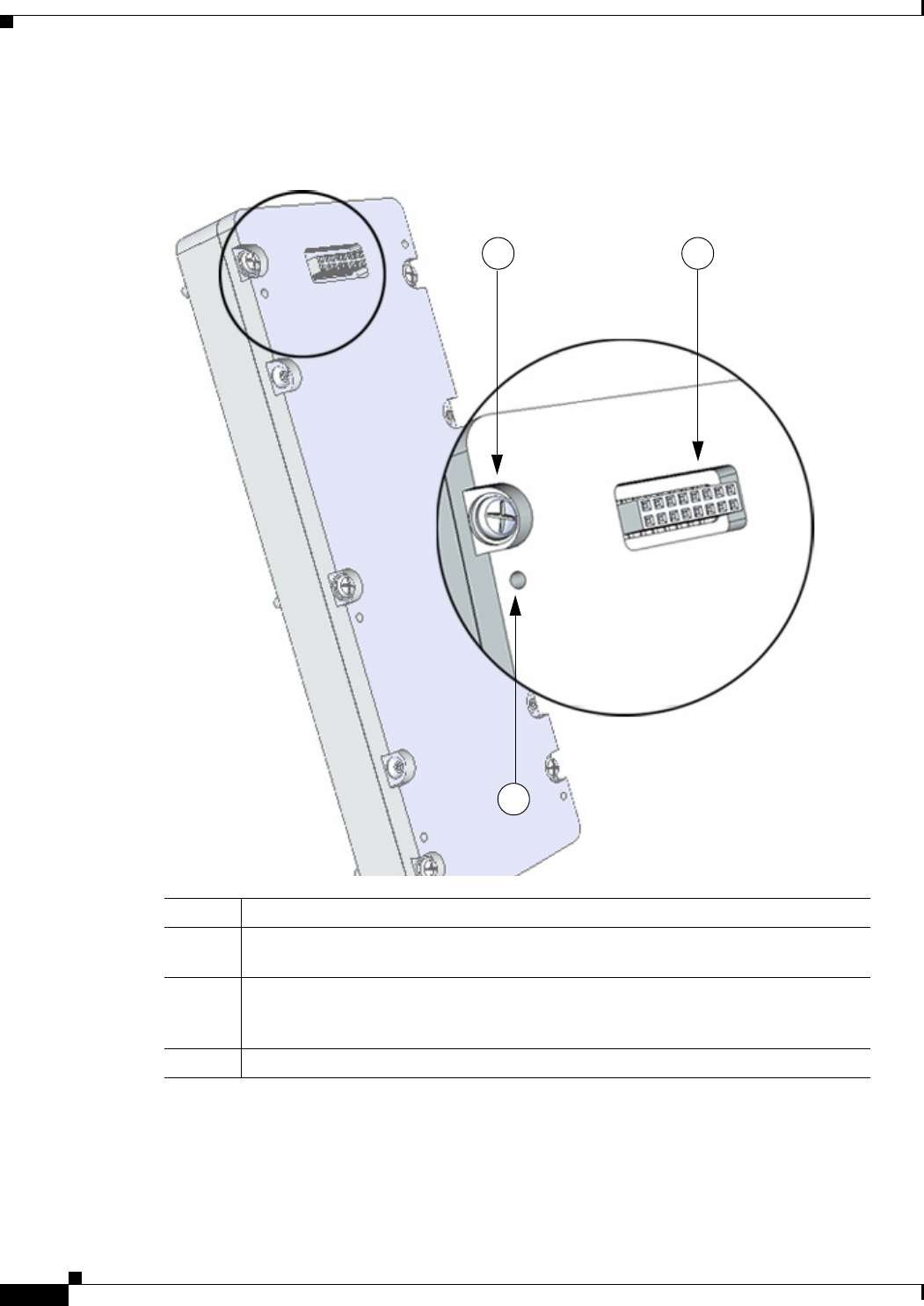
Battery-to-Router Connector
The BBU features a single battery-to-router connector at the base, which connects to the the BBU cable
inside the router (shown in Figure 10-6).
Figure 10-4 Battery-to-Router Connector
DEC. 2011—EFT REVIEW DRAFT—CISCO CONFIDENTIAL
10-9
Cisco 1240 Connected Grid Router Hardware Installation Guide
OL-26223-01
Chapter 10 Installing Battery Backup Units
Preparing to Install the BBU
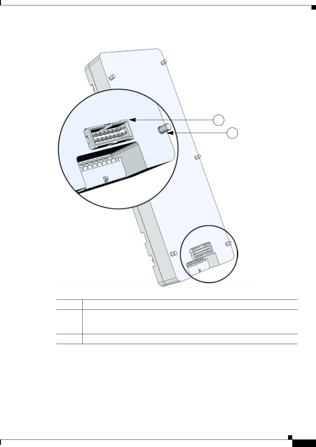
Locating Pin and Notch
When you connect a second or third battery to a battery already installed in the router, as described in
Installing a BBU in the Router, page 10-10, use the locating pin and notch to ensure correct battery
position and align the battery connectors.
Figure 10-5 illustrates the pin and notch location on the BBU.
Figure 10-5 Locating Pin and Notch
Item Description
1Locating notch (back of BBU)
2Locating pin (front of BBU)
1 2

DEC. 2011—EFT REVIEW DRAFT—CISCO CONFIDENTIAL
10-10
Cisco 1240 Connected Grid Router Hardware Installation Guide
OL-26223-01
Chapter 10 Installing Battery Backup Units
Installing a BBU in the Router
Installing a BBU in the Router
Online Insertion and Removal (OIR) or “Hot Swapping”
BBUs can be installed in the router while the router is powered on and operating normally.
Installation Illustrations
The procedures in this section refer to the following illustrations:
• BBU components illustrated in BBU Components, page 10-5
• Router installation features shown in Figure 10-6
• BBU installation assembly shown in Figure 10-7
Installation Procedures
This section includes steps for the following procedures:
• Installing BBU 1, page 10-12
• Installing BBU 2 or BBU 3, page 10-13
DEC. 2011—EFT REVIEW DRAFT—CISCO CONFIDENTIAL
10-11
Cisco 1240 Connected Grid Router Hardware Installation Guide
OL-26223-01
Chapter 10 Installing Battery Backup Units
Installing a BBU in the Router
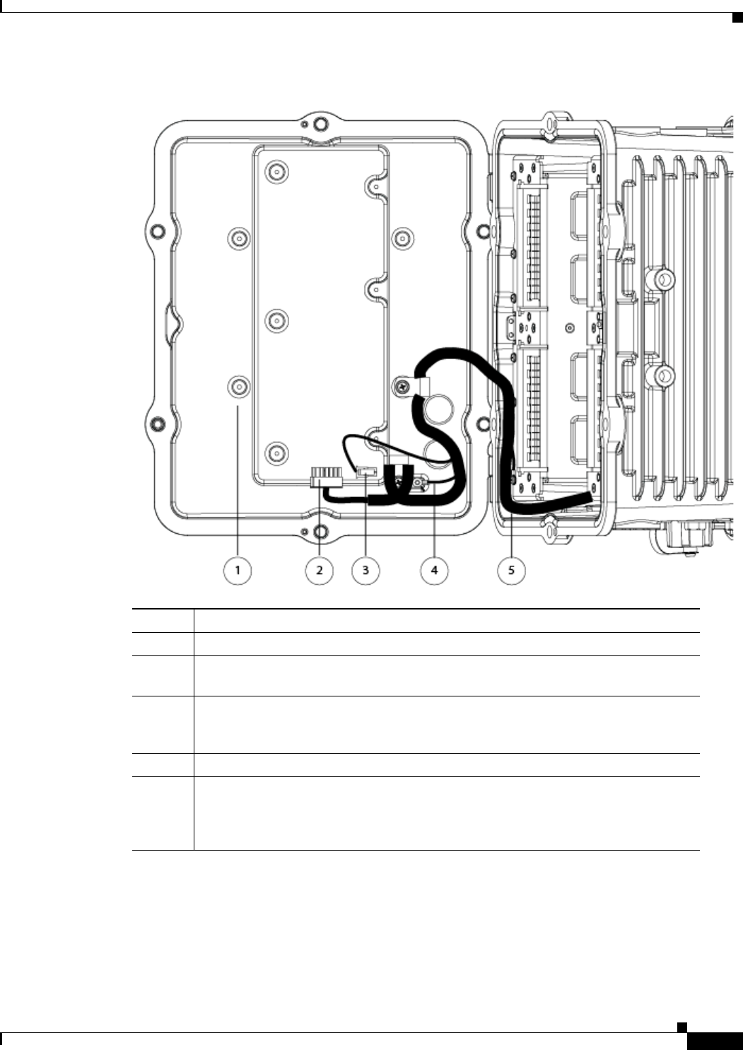
Figure 10-6 Router Features for BBU Installation
Item Description
1Mounting bosses, for installing first BBU to router (6)
2BBU cable connector. The BBU is connected to the router cable harness with this
connecctor.
3Non-Cisco module power connector (12 V). If you install a non-Cisco module on the
router exterior, you can optionally use this connector to provide power to the module.
See the chapter Installing Non-Cisco Modules for details.
4Ground lug (door to chassis)
5BBU cable harness. The cable harness connects the BBU(s) to the router and is the
physical connection over which BBU power is supplied to the router when AC power
is not available. The router is shipped with this cable even if the router is not shipped
with a BBU installed.
DEC. 2011—EFT REVIEW DRAFT—CISCO CONFIDENTIAL
10-12
Cisco 1240 Connected Grid Router Hardware Installation Guide
OL-26223-01
Chapter 10 Installing Battery Backup Units
Installing a BBU in the Router
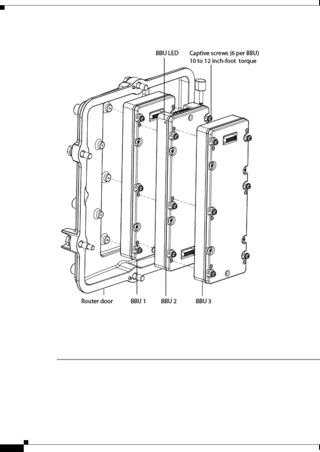
Figure 10-7 BBU Installation
Installing BBU 1
Follow these steps to install BBU 1 (the first BBU) in the router. If you are Installing BBU 2 or BBU 3,
you take different steps.
Step 1 Open the chassis door by following the steps in the chapter Opening the Router Chassis.
Step 2 Align the BBU so that the locating notch and the female battery-to-battery connector are facing out and
the connector is at the top of the router (Figure 10-7).
Step 3 Align the six captive screws on the BBU to the mounting bosses on the router door (Figure 10-7).
Step 4 Use your hand to loosely and evenly install the six captive screws into the mounting bosses, then use the
#1 Phillips screwdriver to tighten the screws using 10 to 12 inch-pounds of torque.

DEC. 2011—EFT REVIEW DRAFT—CISCO CONFIDENTIAL
10-13
Cisco 1240 Connected Grid Router Hardware Installation Guide
OL-26223-01
Chapter 10 Installing Battery Backup Units
Installing a BBU in the Router
Step 5 Connect the BBU cable connector to the battery-to-router connector on the BBU. The connector is
shown in Figure 10-6.
Step 6 Verify that the BBU has been successfully installed and is operating normally by viewing the status of
the Battery Backup Unit LED, page 10-14. The LED will display the following sequence:
a. Red fast blinking—BBU is powered on and is initializing.
b. Red and green alternate blinking— BBU is synchronzing with the router.
c. The final BBU LED state is one of the following:
• Blinking amber—BBU detects that there is no AC power supplied to the router and begins
discharging (supplying power to the router).
• Blinking green—The BBU was not fully charged when installed and is charging to full capacity.
The router is powered by the AC power supply.
• Solid green—The BBU is fully charged. The router is powered by the AC power supply.
Step 7 Close the chassis door by following the steps in the chapter Opening the Router Chassis.
Installing BBU 2 or BBU 3
Follow these steps to install BBU 2 or BBU 3 (a second or third BBU) in the router. Installing BBU 1
requires a different set of steps.
Step 1 Open the chassis door by following the steps in the chapter Opening the Router Chassis.
Step 2 Align the BBU so that thelocating pin and the female battery-to-battery connector are facing out and the
locating notch is at the top of the router.
Step 3 Slide the locating notch on the new BBU over the locating pin on the installed battery, and verify that
the BBU male connector on the new BBU is aligned with the female connector on the installed BBU.
Step 4 Press firmly against the new BBU to seat the connectors and connect the new BBU to the installed BBU.
Step 5 Use your hand to loosely and evenly tighten the six captive screws on the new BBUinto the
corresponding six threaded connectors on the installed BBU. Then use the #1 Phillips screwdriver to
tighten the screws to the installed BBU using 10 to 12 inch-pounds of torque
Step 6 Verify that the BBU has been successfully installed and is operating normally by viewing the status of
the Battery Backup Unit LED, page 10-14. The LED will display the following sequence:
a. Red fast blinking—BBU is powered on and is initializing.
b. Red and green alternate blinking— BBU is synchronzing with the router and the other BBUs.
c. The final BBU LED state is one of the following:
• Blinking amber—BBU detects that there is no AC power supplied to the router and begins
discharging (supplying power to the router).
• Blinking green—The BBU was not fully charged when installed and is charging to full capacity.
The router is powered by the AC power supply.
• Solid green—The BBU is fully charged. The router is powered by the AC power supply.
Step 7 Close the chassis door by following the steps in Opening the Router Chassis.
DEC. 2011—EFT REVIEW DRAFT—CISCO CONFIDENTIAL
10-14
Cisco 1240 Connected Grid Router Hardware Installation Guide
OL-26223-01
Chapter 10 Installing Battery Backup Units
Battery Backup Unit LED
Battery Backup Unit LED
The BBU features a single LED that indicates the status of the BBU when it is installed in the router.
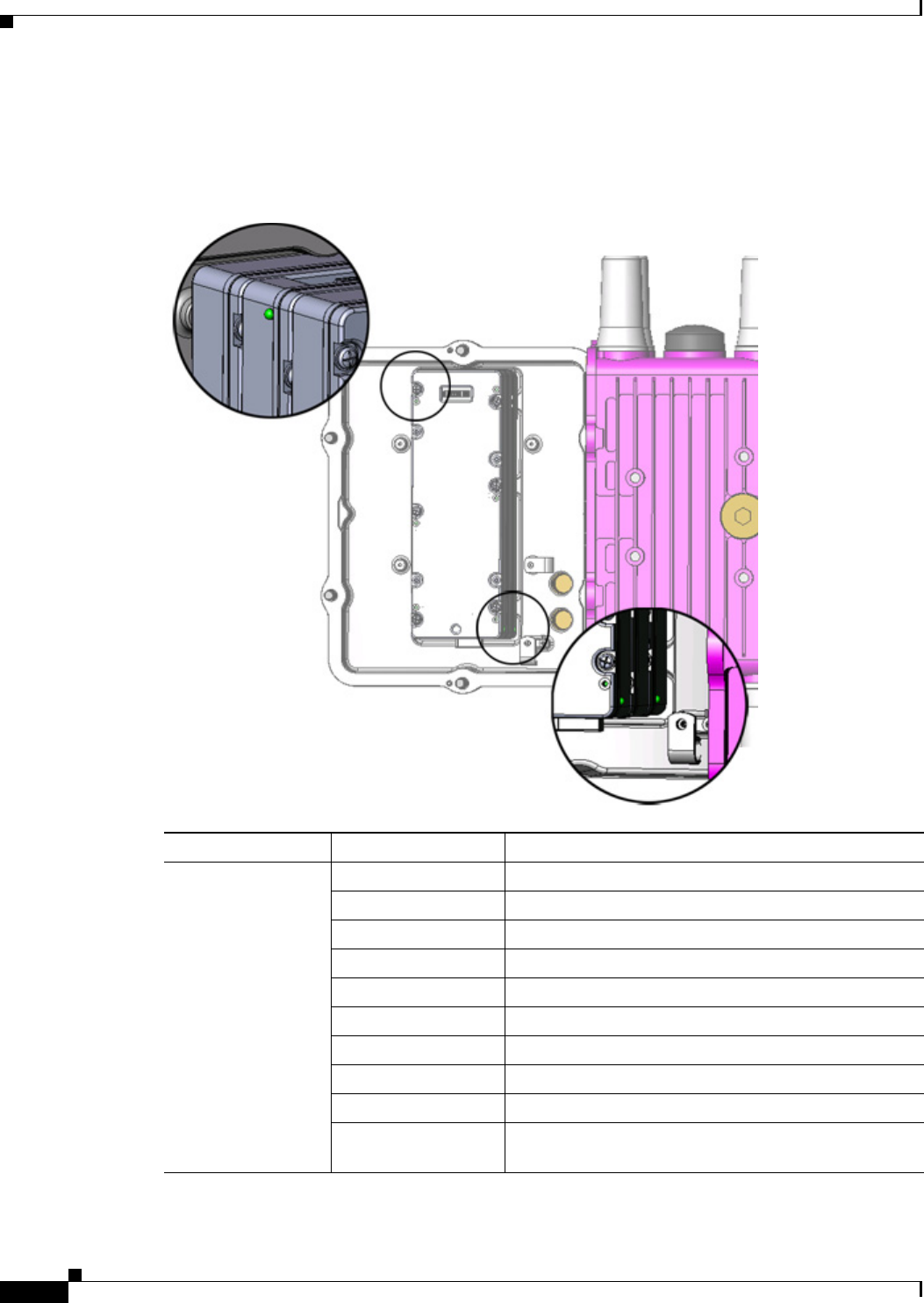
Figure 10-8 Battery Backup Unit LED Location
LED Color and State Description
BBU LED (no label) Green solid Idle state
Green blinking Charging
Amber blinking Discharging (providing power to the system)
Amber slow blinking Disabled with the system software
Red/green blinking Initializing
Red fast blinking Resetting
Red blinking Bootloader mode
Red slow blinking Test mode
Red solid BBU failure
Off Disabled (disconnected from router or completely
discharged)

DEC. 2011—EFT REVIEW DRAFT—CISCO CONFIDENTIAL
10-15
Cisco 1240 Connected Grid Router Hardware Installation Guide
OL-26223-01
Chapter 10 Installing Battery Backup Units
Related Commands
Related Commands
This section describes system software command that support BBU operation, and includes the
following commands:
• backup-battery reset, page 10-15
• backup-battery inhibit discharge, page 10-15
• poweroff module number backup-battery, page 10-16
backup-battery reset
Use the backup-battery reset EXEC command to power the BBU off, then back on:
CGR1240# battery-backup reset
This command is functional only when AC power is supplying power to the router. If you enter this
command when the router is powered by the BBU, an error message is displayed.
This command resets all BBUs installed in the router.
backup-battery inhibit discharge
Use the backup-battery inhibit discharge EXEC command to disable the BBU automatic discharge
feature. Use this command when you must disconnect the router from AC power and want to prevent the
BBU from automatically discharging, for example when you must service the router or transport it
between locations.
This command is functional only when the BBU is supplying power to the router. If you enter this
command when the router is powered by AC power, an error message is displayed.
Caution Entering the backup-battery inhibit discharge command disables the BBU immediately. You are not
prompted to confirm the command. If you enter this command when the router is operating on the
network and powered by the BBU, the router will immediately power down and no longer operate on the
network.
backup-battery un-inhibit discharge
Take these step to reset the BBU to the default behavior (automatically begin discharging when the
router is not receiving AC power):
Step 1 Connect the router to an AC power source.
Step 2 Enter the backup-battery un-inhibit discharge EXEC command:
CGR1240# battery-backup un-inhibit discharge
DEC. 2011—EFT REVIEW DRAFT—CISCO CONFIDENTIAL
10-16
Cisco 1240 Connected Grid Router Hardware Installation Guide
OL-26223-01
Chapter 10 Installing Battery Backup Units
BBU Technical Specifications
poweroff module number backup-battery
Use the poweroff module number backup-battery global configuration command to configure the
router to power off specific modules (including the Ethernet switch) when the router switches to BBU
power. By default, all modules continue to operate normally when the router is powered by the BBU.
Enter this command for each module that you want to automatically shut down.
For example, to configure the router to shut down the Ethernet switch (all Ethernet ports) when the router
is powered by the BBU, enter this command:
CGR1240(config)# poweroff module 2 backup-battery
For example, to configure the router to shut down the module installed in Slot 6 when the router is
powered by the BBU, enter this command:
CGR1240(config)# poweroff module 6 backup-battery
Use the no form of the command to reset a module to the default behavior: continue to operate normally
when the router switches to BBU power. For example:
CGR1240(config)# no poweroff module 2 backup-battery
For detailed information on configuring the router, including configuration modes and saving
configurations, see the Cisco 1000 Series Connected Grid Routers software configuration guides.
BBU Technical Specifications
This section describes the specifications and standards supported by the BBU.
Note For BBU connector and cable specifications, see the appendix Connector and Cable Specifications.
Router Power Path Selection
During normal operation, the router is powered by the integrated AC power supply. The BBU is enabled
when the AC power is interrupted outside a range of 85V to 250V for more than 20 ms.
Syntax Description
poweroff module number backup-battery Configures the router to power down the indicated
module when the router switches to BBU power.
number—The number of module that is powered down:
• 2: Ethernet switch module (all ports)
• 3-6: Module inserted in the slot with corresponding
number. Slot numbering is described and illustrated
in the chapter Router Hardware Description.

DEC. 2011—EFT REVIEW DRAFT—CISCO CONFIDENTIAL
10-17
Cisco 1240 Connected Grid Router Hardware Installation Guide
OL-26223-01
Chapter 10 Installing Battery Backup Units
BBU Technical Specifications
Discharge Conditions
Table 10-2 Battery Backup Unit—Power Path Selection
Behavior Operating Condition
BBU Charge/Discharge Supports charging or discharging only (not both simultaneously)
Total power provided AC power provides up to 60W of power to the router as follows:
• 40W for router operation
• 20W for heater and BBU charging
Table 10-3 Battery Backup Unit—Discharging Specifications
Discharge Conditions Description
Power load 10 W
Duration 4 hours
Entry to discharge1
1. All conditions met.
• BBU cable harness is installed
• AC power (range of 85V to 250V) not detected for more than 20 ms
• Remaining BBU capacity >5%
• Ambient temperature is within -20 to 60 C
Exit discharge2
2. Any condition met and system is detected.
• AC power restored in the range of 85V to 250V for more than 20 ms.
• Remaining BBU capacity <5%
• Ambient temperature not within -20 to 60 C
DEC. 2011—EFT REVIEW DRAFT—CISCO CONFIDENTIAL
10-18
Cisco 1240 Connected Grid Router Hardware Installation Guide
OL-26223-01
Chapter 10 Installing Battery Backup Units
BBU Technical Specifications
Charge Conditions
Operating and Storage Temperatures
Battery Life
Table 10-4 Battery Backup Unit—Charge Specification s
Charge Conditions Description
Power draw No more than 20 W when charging
State of charge No more than 90%
Entry to charging1
1. All conditions are met.
• BBU cable harness is installed
• Charge is enabled
• SoC <90%
• Ambient temperature is within 0 to 50C
• AC power detected in the range of 85V to 250V for more than 20 ms.
Exit charging2
2. Any condition is met
• BBU cable harness not installed
• Charge is disabled
• AC power (range of 85V to 250V) not detected for more than 20 ms.
• Ambient temperature is not within 0 to 50 C
Table 10-5 Battery Backup Unit—Operating and Storage Temperatures
BBU State Temperature Range
Battery charging 0 to 50 C (32 to 122 F)
Battery discharging -20 to 60 C (-4 to 140 F)
Operating -40 to 85 C (-40 to 185 F)
Storage and shipping -40 to 70 C (-40 to 158 F)
Table 10-6 Battery Backup Unit — Battery Life
Product ID Battery Life Charge-Discharge Cycles
CGR-BATT-4AH 5 years 500

DEC. 2011—EFT REVIEW DRAFT—CISCO CONFIDENTIAL
10-19
Cisco 1240 Connected Grid Router Hardware Installation Guide
OL-26223-01
Chapter 10 Installing Battery Backup Units
BBU Technical Specifications
Battery Standards
Table 10-7 lists the equipment standards that the BBU supports.
Table 10-7 Supported Safety Standards
Name Description of Standard
UL2054 Household and Commercial Batteries
UL60950-1 Information Technology Equipment

DEC. 2011—EFT REVIEW DRAFT—CISCO CONFIDENTIAL
10-20
Cisco 1240 Connected Grid Router Hardware Installation Guide
OL-26223-01
Chapter 10 Installing Battery Backup Units
BBU Technical Specifications
CHAPTER
DEC. 2011—EFT REVIEW DRAFT—CISCO CONFIDENTIAL
11-1
Cisco 1240 Connected Grid Router Hardware Installation Guide
OL-26223-01
11
Installing Non-Cisco Modules
The Cisco 1240 Connected Grid Router provides support for a compatible, non-Cisco wireless module,
installed on the router exterior and connected to the router integrated switch module. Wireless
connections send data from the router to field devices, such as smart meters, and from the router to the
utility or data management center.
This chapter contains the following sections:
• Non-Cisco Module Support, page 11-1
• Before Installing, page 11-2
• Install a Non-Cisco Module, page 11-3
• Related Information, page 11-9
Non-Cisco Module Support
This section describes the support for, and requirements for, installing a non-Cisco module on the router.
Caution Cisco does not provide technical support for issues related to non-Cisco products. You must contact the
module supplier or your reseller to obtain technical support for the non-Cisco module.
Caution Installing a module that does not meet these requirements can negatively affect router performance.
Non-Cisco Module Requirements
Non-Cisco modules installed on the router exterior must meet the following requirements:
• Must comply with Type 4X and IP67 standards.
• External devices must have one of the following sets of dimensions:
–
7 x 4 x 2.5 inches (17.78 x 10.16 x 6.35 cm)
Reviewers: Provide the supported dimensions for the configuration shown in Figure 11-2.

DEC. 2011—EFT REVIEW DRAFT—CISCO CONFIDENTIAL
11-2
Cisco 1240 Connected Grid Router Hardware Installation Guide
OL-26223-01
Chapter 11 Installing Non-Cisco Modules
Before Installing
Online Installation and Removal
A non-Cisco module can be installed or removed while the router is installed (usually on a pole top) and
operating normally.
Reviewers: Please confirm the above statement.
Certification
A non-Cisco module that is installed on the router does not interact with the router chassis. Connecting
a non-Cisco module to the router does not certify the module. Before installing the module, verify that
it is certified for use in your environment.
Power
The router interior features a 4-pin, Micro-Fit 3.0 connector, which provides 12 volts of power to a
connected module. See Figure 11-5 for an illustration of the power connector.
Before Installing
Read this section and the Installation Safety and Site Preparation chapter before following any
installation procedures in this chapter.
Prepare the Installation Site
The procedures in this chapter assume that you have prepared the installation site according to the
information in the Installation Safety and Site Preparation chapter.
Read the Safety Information
Before performing any of the tasks in this chapter, you must read the safety warnings in this section and
in the Installation Safety and Site Preparation chapter.
Preventing Electrostatic Discharge Damage
Many of the components discussed in this chapter are sensitive to electrostatic discharge (ESD) damage,
which can occur when electronic cards or components are handled improperly, results in complete or
intermittent failures.
To prevent ESD damage, follow these guidelines:
• Always use an ESD wrist or ankle strap and ensure that it makes good skin contact.
• Connect the equipment end of the strap to an unfinished chassis surface.
• Place a removed the memory card on an antistatic surface or in a static shielding bag. If the card will
be returned to the factory, immediately place it in a static shielding bag.

DEC. 2011—EFT REVIEW DRAFT—CISCO CONFIDENTIAL
11-3
Cisco 1240 Connected Grid Router Hardware Installation Guide
OL-26223-01
Chapter 11 Installing Non-Cisco Modules
Install a Non-Cisco Module
• Avoid contact between the card and clothing. The wrist strap protects the card from ESD voltages
on the body only; ESD voltages on clothing can still cause damage.
• Do not remove the wrist strap until the installation is complete.
Cabling Guidelines
Follow these guidelines for using cables with the router:
• Position cables so that they do not place strain on the router connectors.
• Organize cables into bundles when necessary to avoid intertwining.
• Inspect cables to ensure adequate routing and bend radius.
• Install cable ties that comply with your site requirements.
Install a Non-Cisco Module
This section provides the information you need to connect a non-Cisco module to the router. Some steps
might require that you refer to the documentation that supports the module. This section includes these
installation topics:
• Tools and Materials You Supply, page 11-3
• Open and Close the Router Door, page 11-3
• Connect the Module to the Chassis, page 11-4
• Cabling Instructions, page 11-6
• Connect to the Network, page 11-8
• Connect to Power, page 11-9
Tools and Materials You Supply
• Wrench—You must supply a 13-mm box-end wrench or socket set to remove liquid-tight seals from
the cable ports and to install the cable glands on the cable ports.
• Hardware—You must provide any hardware required to Connect the Module to the Chassis,
page 11-4.
• Power Connector Adapter—Depending on your module power cable, you might need to provide
an adapter to connect the module to the router 4-pin Micro-Fit 3.0 power connector.
Open and Close the Router Door
You might be required to open the router door to install the module. For instructions on opening and
closing the router door, see the chapter Opening the Router Chassis.
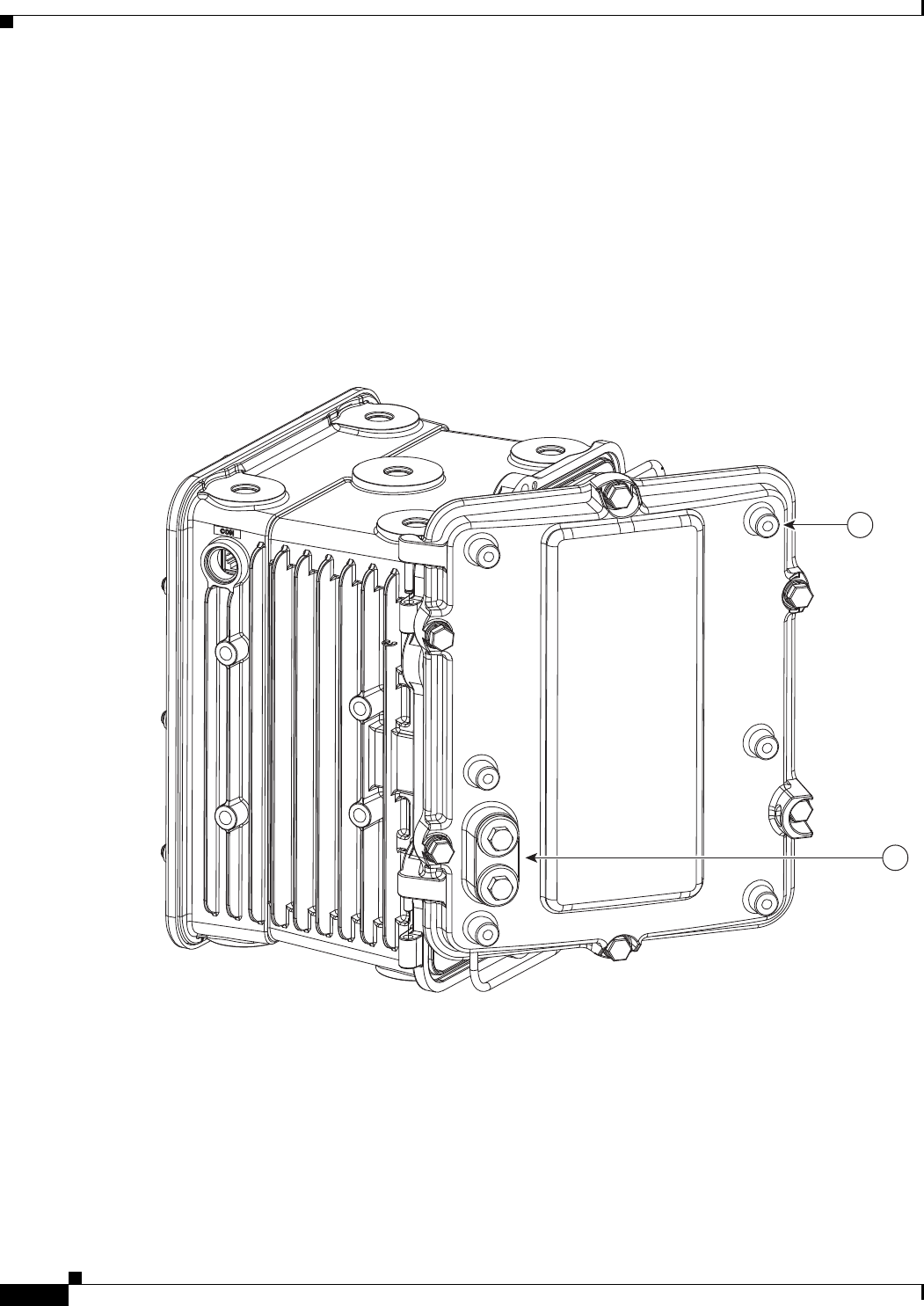
DEC. 2011—EFT REVIEW DRAFT—CISCO CONFIDENTIAL
11-4
Cisco 1240 Connected Grid Router Hardware Installation Guide
OL-26223-01
Chapter 11 Installing Non-Cisco Modules
Install a Non-Cisco Module
Connect the Module to the Chassis
The router front door has these features for installing a module on the router exterior:
• Six mounting bosses for attaching a module to the router (see 1 in Figure 11-1)
• Two cable ports to thread power and Ethernet cables to the router interior (see 2 in Figure 11-1)
To attach the module to the mounting bosses, you must:
• Provide the hardware required to attach the module to the mounting bosses
• Follow the mounting instructions that support the module
Figure 11-1 Mounting Bosses and Cable Ports
Installation Options
The layout of the mounting bosses on the router front door supports two typical installation options,
described in this section:
• External Cabling Installation Configuration, page 11-5
• Internal Cabling Installation Configuration, page 11-6
300527
1
2
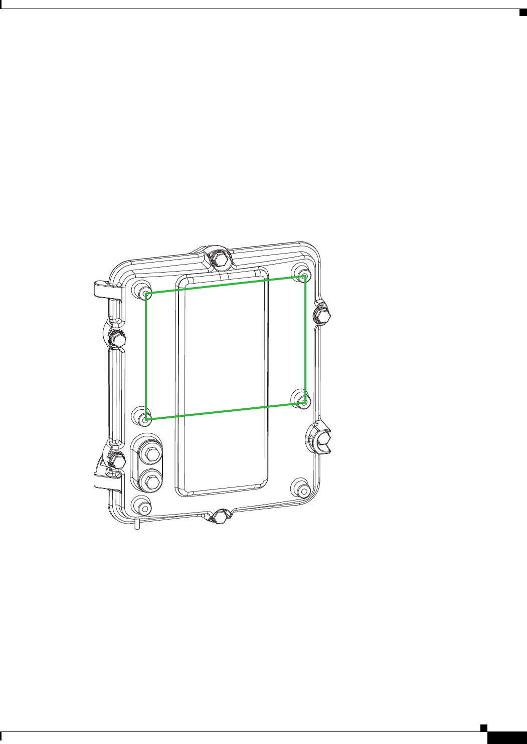
DEC. 2011—EFT REVIEW DRAFT—CISCO CONFIDENTIAL
11-5
Cisco 1240 Connected Grid Router Hardware Installation Guide
OL-26223-01
Chapter 11 Installing Non-Cisco Modules
Install a Non-Cisco Module
External Cabling Installation Configuration
In the configuration shown in Figure 11-2, install the module above the cable ports, and connect the
cables from the module through the cable ports on the router door.
With this configuration:
• Use the four mounting bosses indicated in Figure 11-2.
• Supported dimensions: (Need this information from hardware/mechanical engineering.)
• Cables are exposed externally
• Use cable glands to thread cables through the cable ports
• Follow the cabling instructions in External Cabling, page 11-7
Figure 11-2 Non-Cisco Module Installation Configuration—External Cabling
300528
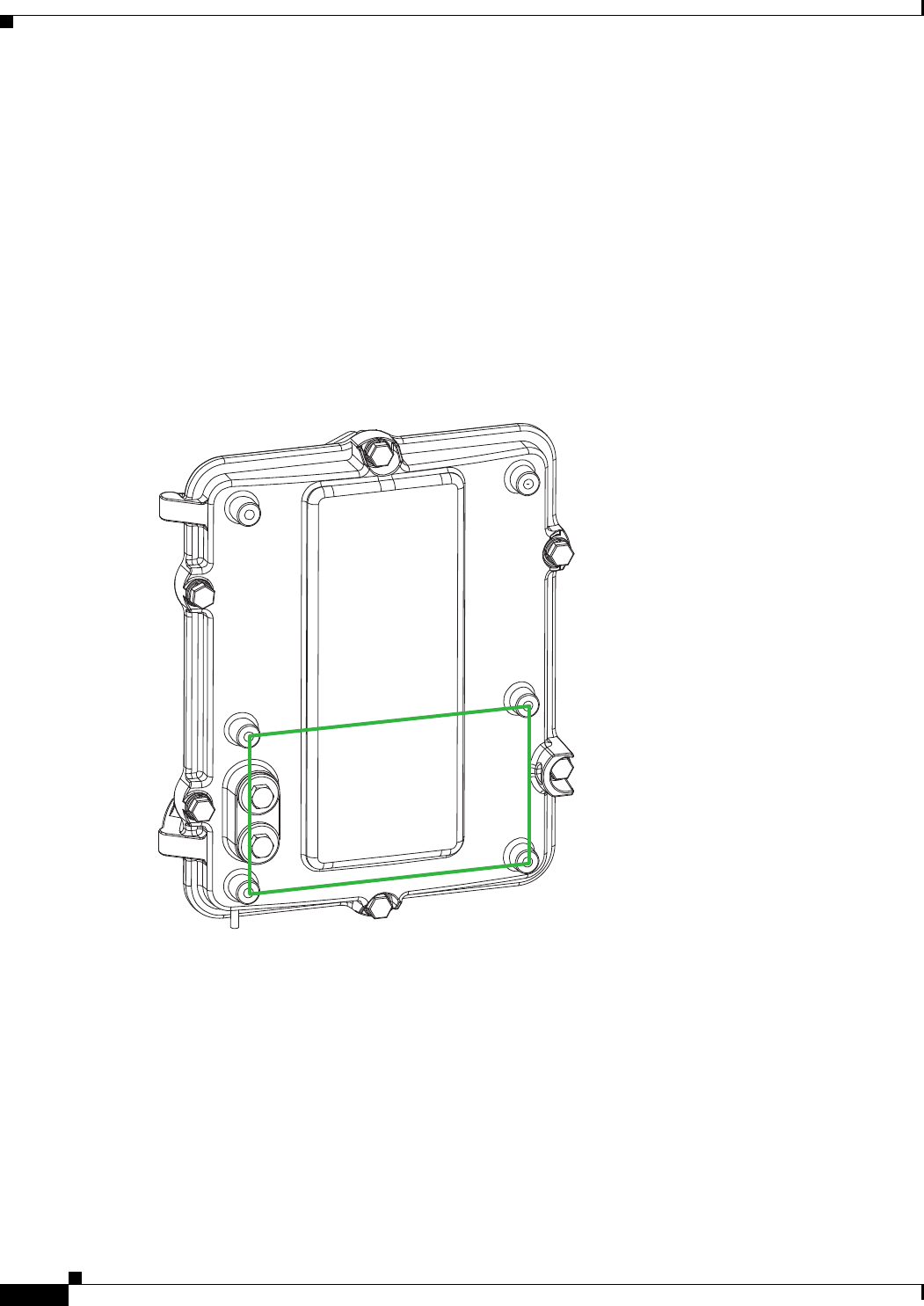
DEC. 2011—EFT REVIEW DRAFT—CISCO CONFIDENTIAL
11-6
Cisco 1240 Connected Grid Router Hardware Installation Guide
OL-26223-01
Chapter 11 Installing Non-Cisco Modules
Install a Non-Cisco Module
Internal Cabling Installation Configuration
In the configuration shown in Figure 11-3, install the module directly over the cable ports, and thread
the module cables through the cable ports.
With this configuration:
• Use the four mounting bosses indicated in Figure 11-3
• Supported dimensions: 7 x 4 inches (17.78 x 10.16 cm)
• Cables are not exposed externally
• Install an O-ring in each cable port to create an environment-proof seal
• Follow the cabling instructions in Internal Cabling, page 11-7
Figure 11-3 Non-Cisco Module Installation Configuration—Internal Cabling
Cabling Instructions
This section describes the two cabling procedures. Use the procedure that applies to your installation
configuration:
• External Cabling, page 11-7
• Internal Cabling, page 11-7
300529
DEC. 2011—EFT REVIEW DRAFT—CISCO CONFIDENTIAL
11-7
Cisco 1240 Connected Grid Router Hardware Installation Guide
OL-26223-01
Chapter 11 Installing Non-Cisco Modules
Install a Non-Cisco Module
External Cabling
When you install the module in the configuration shown in Figure 11-2, the cables are external to the
router, and then threaded through the cable ports on the router from the module.
Cisco Cable Glands
When you install the module in a configuration that uses external cabling from the module through the
cable ports on the router door, you must provide cable glands for each cable port.
Cable glands:
• Create seal to protect the router interior from environmental elements
• Can be ordered from Cisco: CGR-IP67GLAND (one cable gland per kit)
• Are described in detail in Cable Glands Description, page 6-12 in the Installing the Router chapter
Caution The cable glands must be used for all cables that are threaded through the router chassis cable ports to
prevent exposing the router interior to environmental elements.
Outdoor Cable Requirements
Verify that the cables you use to connect the module to the router meet the cable requirements described
in Cable Requirements, page 6-13 of the Installing the Router chapter.
Connecting the Cable Glands
Step 1 Use the 13-mm wrench to remove the liquid-tight seals from the cable ports on the router door.
Step 2 Follow the steps in Cable Glands Installation Steps, page 6-13, in the Installing the Router chapter to:
• Thread the Ethernet and power cables through the cable glands
• Connect the cable glands to the cable ports on the router door
Internal Cabling
When you install the module in the configuration shown in Figure 11-3, the cables are threaded directly
through the cable ports on the router from the module, and are not exposed externally.
Cisco O-Ring
When you install the module in a configuration that uses internal cabling from the module, through the
cable ports on the router door, insert a rubber O-ring into each port to create an environmental-proof seal.
You can order an O-ring kit from Cisco using the model number xx-xxxxx. Each kit contains one O-ring.
Reviewers: Confirm that this is an orderable part from Cisco.
Caution The O-ring must be used to prevent exposing the router interior to environmental elements.
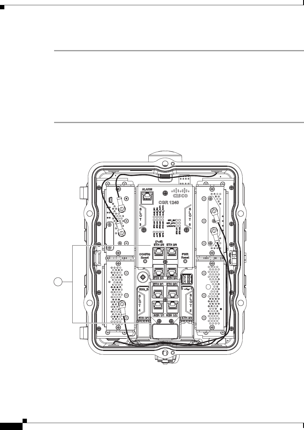
DEC. 2011—EFT REVIEW DRAFT—CISCO CONFIDENTIAL
11-8
Cisco 1240 Connected Grid Router Hardware Installation Guide
OL-26223-01
Chapter 11 Installing Non-Cisco Modules
Install a Non-Cisco Module
Connect to the Network
Step 1 Verify that the module Ethernet cable is threaded through the router cable port, and that the cable port
has cable glands or an O-ring installed.
Step 2 Connect the module Ethernet cable to any of the Ethernet ports on the router interior. See in 1 in
Figure 11-4 for router Ethernet port locations.
For detailed information about making router Ethernet connections, see Connect to the Ethernet
Backhaul Network, page 6-3, in the Installing the Router.
Step 3 After connecting the module network cable to the Ethernet port, use the wire ties on the router door (see
in 1 in Figure 11-5) to fix the cable to the door.
Figure 11-4 Router Ethernet Ports (1)
1
300526
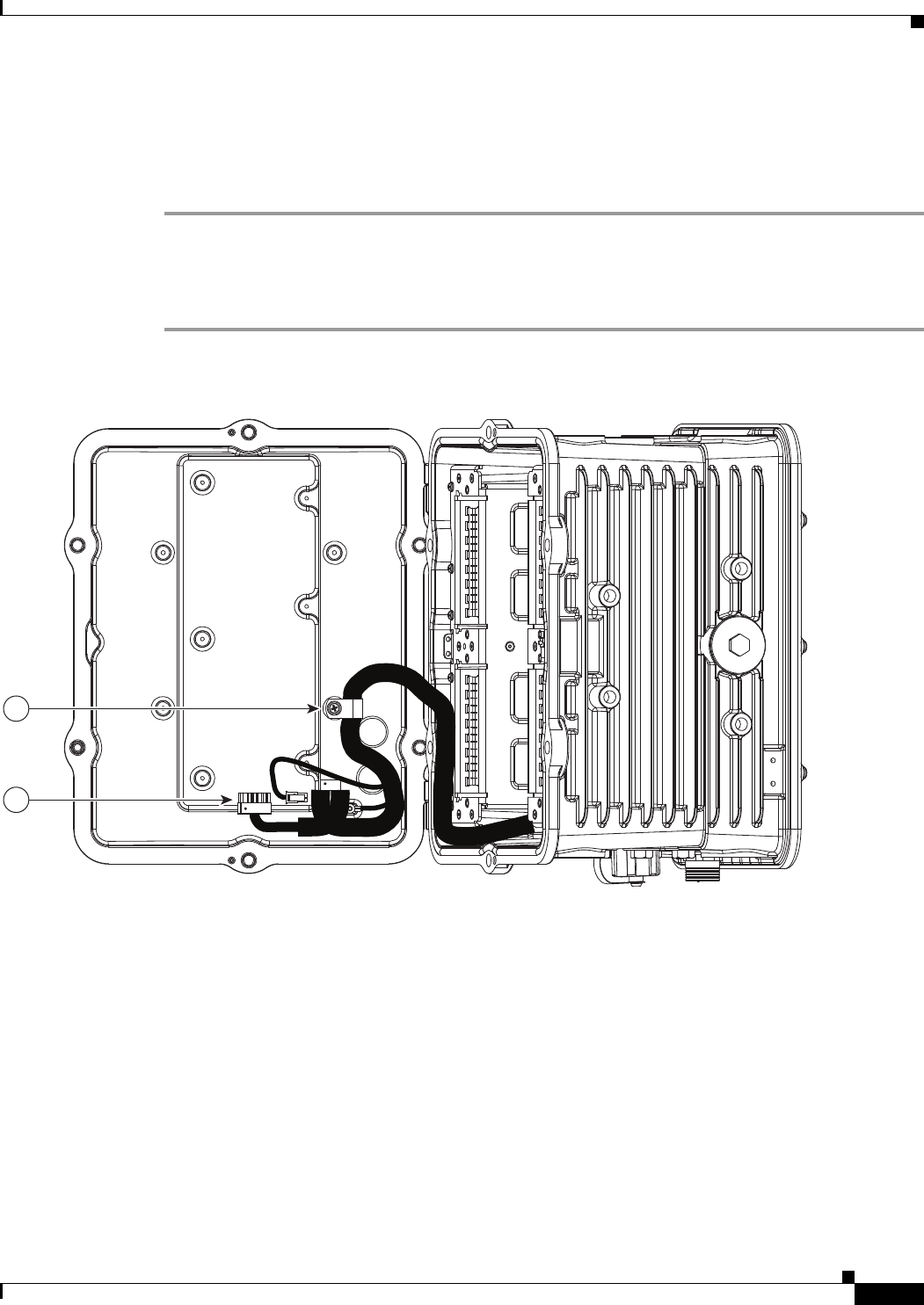
DEC. 2011—EFT REVIEW DRAFT—CISCO CONFIDENTIAL
11-9
Cisco 1240 Connected Grid Router Hardware Installation Guide
OL-26223-01
Chapter 11 Installing Non-Cisco Modules
Related Information
Connect to Power
Depending on your module power cable, you might need to provide an adapter to connect the module to
a 4-pin Micro-Fit 3.0 power connector.
Step 1 Verify that the module power cable is threaded through the router cable port, and that the cable port has
cable glands or an O-ring installed.
Step 2 Connect the power cable to the Micro-Fit 3.0 power connector. See in 2 in Figure 11-5 for connector
location.
Figure 11-5 Cable Harness (1) and Power Connector (2)
Related Information
This chapter describes installation procedures. For detailed, technical information about the router
hardware, including connector and cable descriptions, specifications, and pinouts, see the following
chapters:
• The Router Hardware Description chapter describes all features of the router hardware, including
the ports and cable glands described in this chapter.
• The Connector and Cable Specifications appendix includes the pinouts for the 12V power connector
used to provide power to non-Cisco modules.
1
2
300525

DEC. 2011—EFT REVIEW DRAFT—CISCO CONFIDENTIAL
11-10
Cisco 1240 Connected Grid Router Hardware Installation Guide
OL-26223-01
Chapter 11 Installing Non-Cisco Modules
Related Information

CHAPTER
DEC. 2011—EFT REVIEW DRAFT—CISCO CONFIDENTIAL
12-1
Cisco 1240 Connected Grid Router Hardware Installation Guide
OL-26223-01
12
Router LED Locations and States
View the Cisco 1240 Connected Grid Router LEDs to determine the overall state of the system and to
verify the status of specific connections, ports, and system components.
In addition to viewing the LEDs on the router hardware, you can use the router command line interface
as described in the section Related Commands, page 12-8 to check the system status LED state from
remote locations.
This chapter includes the sections:
• LED Locations and State Descriptions, page 12-2
• Related Commands, page 12-8
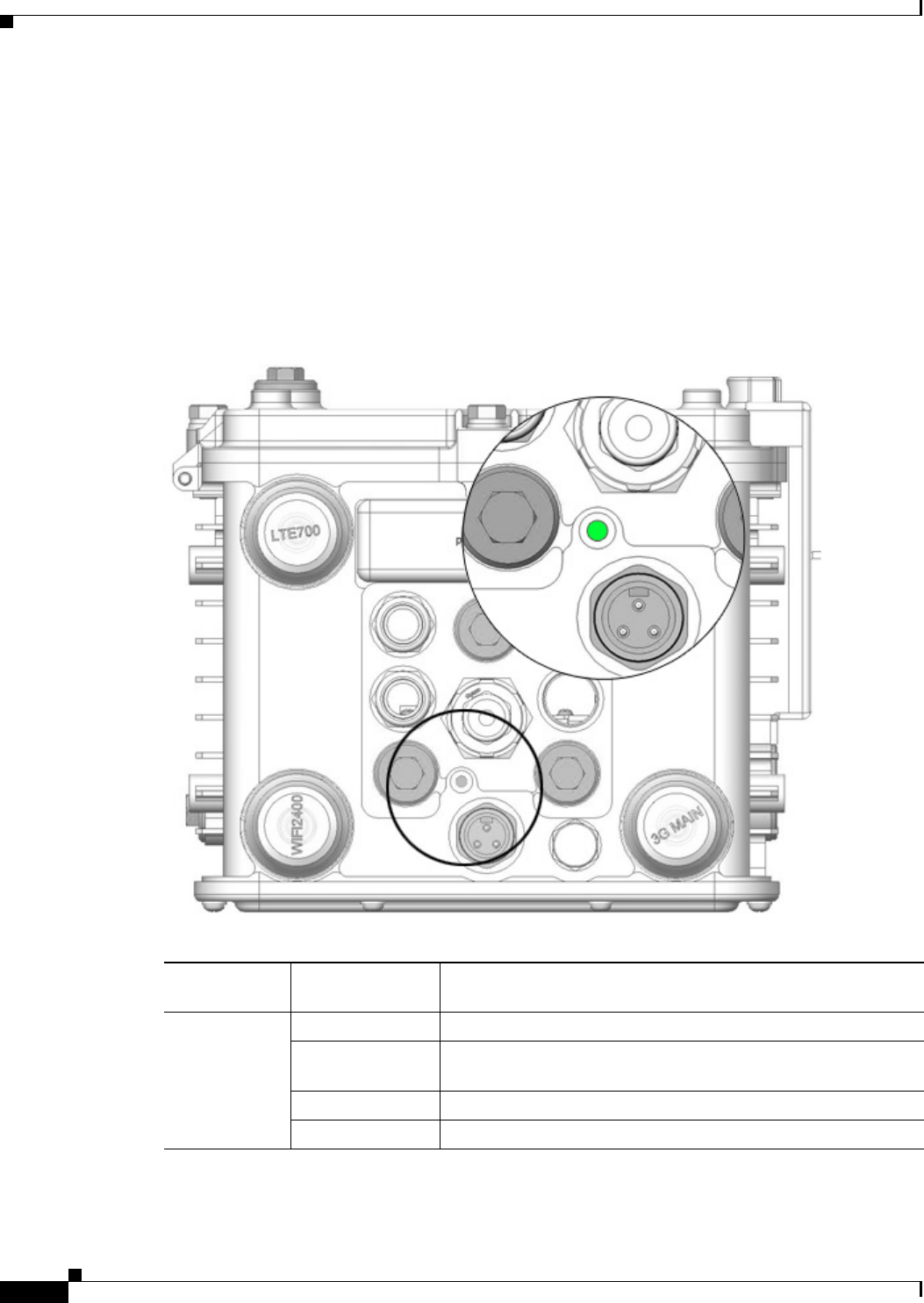
DEC. 2011—EFT REVIEW DRAFT—CISCO CONFIDENTIAL
12-2
Cisco 1240 Connected Grid Router Hardware Installation Guide
OL-26223-01
Chapter 12 Router LED Locations and States
LED Locations and State Descriptions
LED Locations and State Descriptions
System Status (SYS) LED
View the system status LED to determine the overall operating and power status of the router.
A second, identical system status LED is located inside the router. See the section Alarm and Network
Connection LEDs, page 12-3 for the location of the interior SYS LED.
Figure 12-1 System Status LED (SYS) — Router Bottom Exterior
Label
Description Color and State Description
SYS
System status
Green Normal system operating status
Green blinking The system is starting up or power cycling, and loading system
software, including BIOS and operating system
Amber System receiving power but there is an error condition
Off System not receiving power
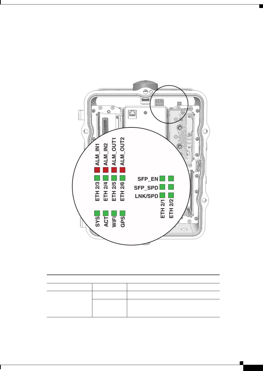
DEC. 2011—EFT REVIEW DRAFT—CISCO CONFIDENTIAL
12-3
Cisco 1240 Connected Grid Router Hardware Installation Guide
OL-26223-01
Chapter 12 Router LED Locations and States
LED Locations and State Descriptions
Alarm and Network Connection LEDs
The router LEDs that indicate network activity and connection status, and the LEDs that indicate alarm
states, are located inside the router. To see these LEDs, you must open the router chassis according to
the instructions in the Opening the Router Chassis chapter.
Figure 12-2 Network and Alarm LEDs — Router Front Interior
ALARM LEDs
Alarm LEDs
LED Label Color and State Meaning
ALM_IN1
ALM_IN2
ALM_OUT1
ALM_OUT2
Off No alarm condition is present on the port
Red solid Alarm condition present on the port
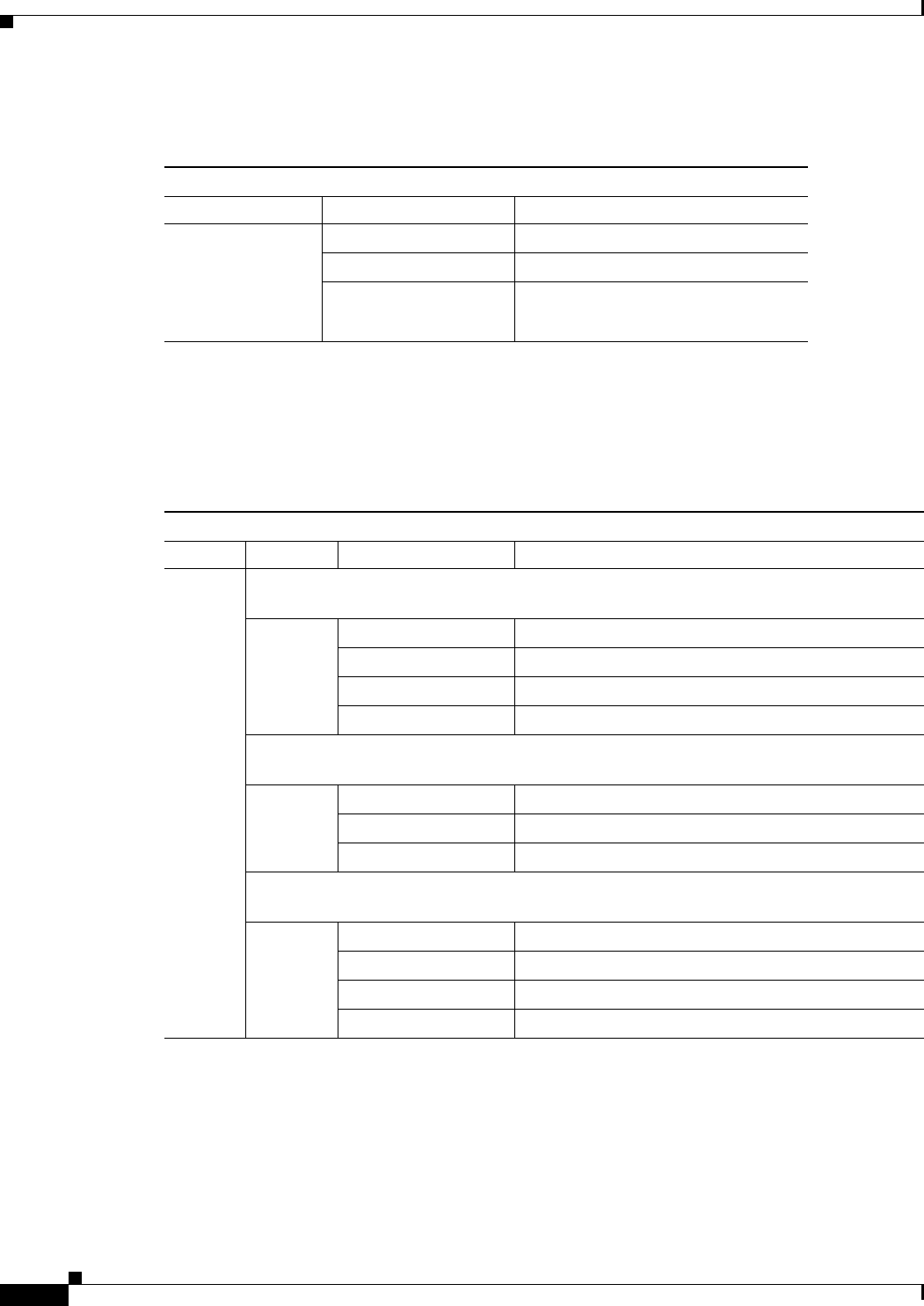
DEC. 2011—EFT REVIEW DRAFT—CISCO CONFIDENTIAL
12-4
Cisco 1240 Connected Grid Router Hardware Installation Guide
OL-26223-01
Chapter 12 Router LED Locations and States
LED Locations and State Descriptions
Fast Ethernet LEDs
Combo Port LEDs
The ETH 2/1 and ETH 2/2 interfaces are shared. Each interface (ETH 2/1 and ETH 2/2) supports either
a fiber optic GE connection (using an SFP module) or a copper GE connection, but not both. For more
information, see Combo Ports, page 2-26 in the chapter Router Hardware Description.
Fast Ethernet LEDs
LED Label Color and State Description
ETH 2/3
ETH 2/4
ETH 2/5
ETH 2/6
Off No link established
Green, 2 blinks/pause 10 MB/s link speed
Green, 1 blink/pause 100 MB/s link speed
Combo Port LEDs–SFP Module and Gigabit Ethernet Ports
LED Label LED Label Color and State Description
ETH 2/1
ETH 2/2
SFP_EN–This LED is active only for fiber optic (SFP module) connections on the ETH 2/1
and ETH 2/2 ports.
Off No SFP installed in the port
Green solid Supported SFP installed in the SFP port
Green blinking SFP module can be removed or replaced
Amber solid Unsupported SFP installed in the SFP port
SFP_SPD–This LED is active only for fiber optic (SFP module) connections on the ETH
2/1 and ETH 2/2 ports.
Green, 3 blink/pause 100 MB/s link speed
Green, 2 blinks/pause 1000 MB/s link speed
Off No SFP link established on the optical GE port
LNK/SPD–This LED is active only for copper GE connections on the ETH 2/1 and ETH
2/2 ports.
Amber, 3 blinks/pause 100 MB/s link speed
Amber, 2 blinks/pause 1000 MB/s link speed
Green solid Ethernet cable connected and link established
Off No link established
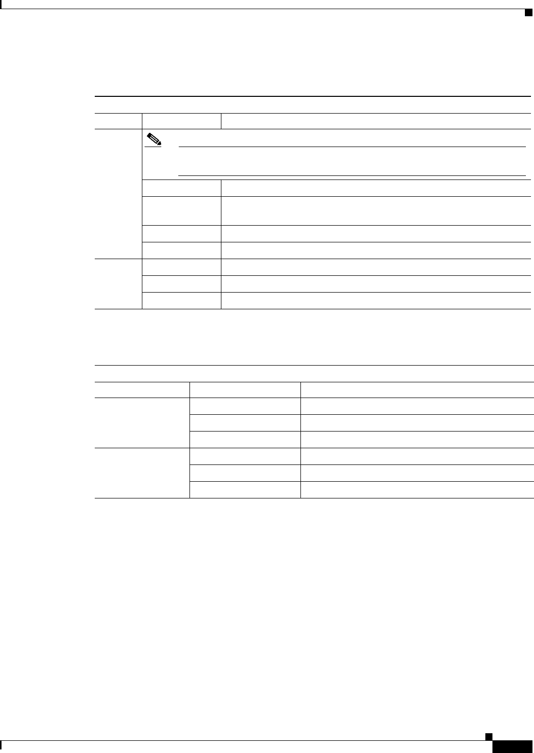
DEC. 2011—EFT REVIEW DRAFT—CISCO CONFIDENTIAL
12-5
Cisco 1240 Connected Grid Router Hardware Installation Guide
OL-26223-01
Chapter 12 Router LED Locations and States
LED Locations and State Descriptions
System LEDs
WiFi and GPS LEDs
System LEDs
LED Label Color and State Description
SYS
Note This LED has the same functionality as the SYS LED on the router exterior,
described in the section System Status (SYS) LED, page 12-2.
Green Normal system operating status
Green blinking The system is starting up or power cycling, and loading system
software, including BIOS and operating system
Amber System receiving power but there is an error condition
Off System not receiving power
ACT Off No system data packet activity
Green System data packet activity between the system and any data port
Green blinking System data packet activity between the system and any data port
WiFi and GPS LEDs
LED Label Color and State Description
WIFI Green WiFi link established
Green blinking WiFi link established and data transfer in progress
Yellow No WiFi link
GPS Green GPS link established
Yellow blinking Establishing link with GPS (in progress)
Yellow solid No GPS link

DEC. 2011—EFT REVIEW DRAFT—CISCO CONFIDENTIAL
12-6
Cisco 1240 Connected Grid Router Hardware Installation Guide
OL-26223-01
Chapter 12 Router LED Locations and States
LED Locations and State Descriptions
Battery Backup Unit LED
The router supports up to three battery backup units (BBUs). When two or more BBUs are installed, they
are connected to each other in a head-to-tail configuration in the router and the the BBU LED are in the
lcoations shown in Figure 12-3.
To see the LED for each BBU, open the router chassis according to the Opening the Router Chassis
chapter.
Figure 12-3 Battery Backup (BAT) LED Location
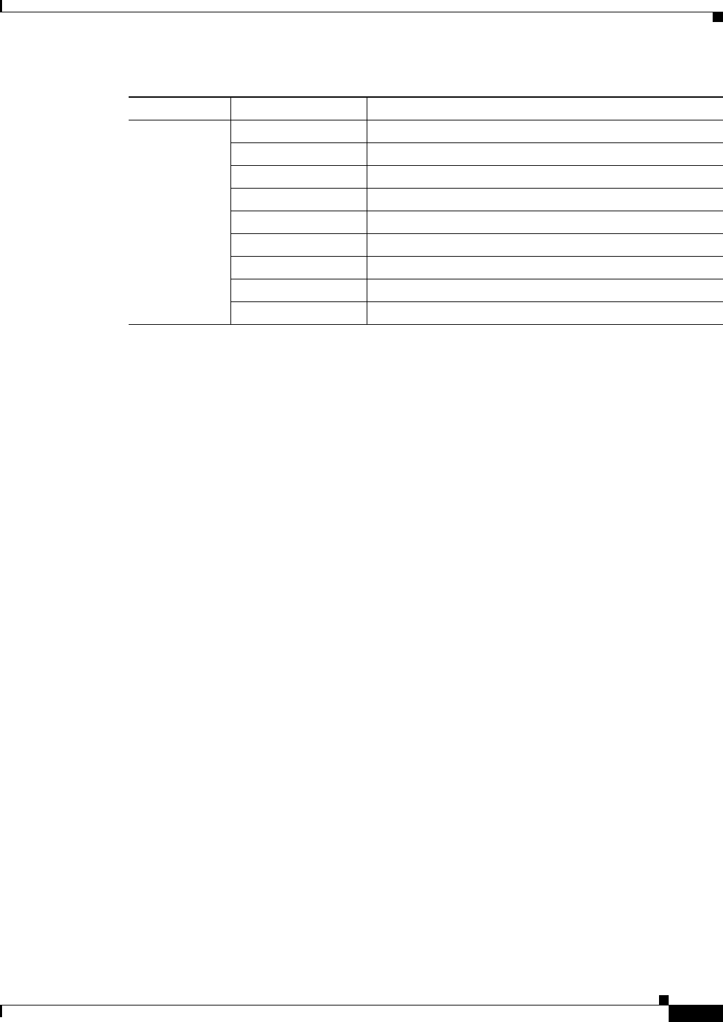
DEC. 2011—EFT REVIEW DRAFT—CISCO CONFIDENTIAL
12-7
Cisco 1240 Connected Grid Router Hardware Installation Guide
OL-26223-01
Chapter 12 Router LED Locations and States
LED Locations and State Descriptions
SD Card (SD0) LED
To see the SD card and the SD LED, you must remove the exterior plug that covers the router SD card
port, as shown here.
LED Color and State Description
BBU (no label) Green solid Idle state
Green blinking Charging
Amber blinking Discharging (providing power to the system)
Amber slow blinking Disabled with the system software
Red/green blinking Initializing
Red blinking Bootloader mode
Red slow blinking Test mode
Red solid BBU failure
Off Disconnected from router or completely discharged
DEC. 2011—EFT REVIEW DRAFT—CISCO CONFIDENTIAL
12-8
Cisco 1240 Connected Grid Router Hardware Installation Guide
OL-26223-01
Chapter 12 Router LED Locations and States
LED Locations and State Descriptions
Figure 12-4 SD Card (SD0)— Router Right Side Exterior
Label Color and State Description
SD0 Green SD flash card installed and operating normally
Green blinking SD flash card data transfer in process
Amber • Error when system accesses the SD flash card
• Router cannot locate a system software image
Amber blinking Unsupported SD card installed in the slot
Amber flashing No SD card installed in slot

DEC. 2011—EFT REVIEW DRAFT—CISCO CONFIDENTIAL
12-9
Cisco 1240 Connected Grid Router Hardware Installation Guide
OL-26223-01
Chapter 12 Router LED Locations and States
Related Commands
Related Commands
You can use router software command line interface (CLI) to view the status of System Status LED
described in the section System Status (SYS) LED, page 12-2. During normal operation, the router can
be installed at the top of an outdoor pole or other inaccessible location, and you might not be able to
view SYS LED on the router hardware. In this case, you can view the status of the LED from a remote
location using the router CLI.
This section includes these commands:
• show led, page 12-8
• show interface, page 12-8
show led
Use the show led command in any command mode to view the status of the router SYS LED.
One SYS LED is located on the router exterior, as shown in Figure 12-1 and the other is located inside
the router chassis, as shown in Figure 12-2.
The values displayed in the System LED field are described in the section System Status (SYS) LED,
page 12-2.
This example shows the show led command output:
CGR-1040> show led
System LED: green, solid
Summary of LED status provider:
Client | State
-------------------------------------------
cellular 3/1 | Blinking
--- end of list ---
CGR-1040>
show interface
To display the status of and information about the router interfaces, use the show interface command in
any command mode.
This example shows the show interface command output:
CGR1240> show interface
Ethernet0 is up, line protocol is up
Hardware is Lance, address is 0019.076c.1a78 (bia 0019.076c.1a78)
Internet address is 172.28.231.193/23
MTU 1500 bytes, BW 10000 Kbit, DLY 1000 usec, rely 255/255, load 1/255
Encapsulation ARPA, loopback not set, keepalive set (10 sec)
ARP type: ARPA, ARP Timeout 04:00:00
Last input 00:00:00, output 00:00:00, output hang never
Last clearing of "show interface" counters never
Queueing strategy: fifo
Output queue 0/40, 0 drops; input queue 5/75, 32 drops
5 minute input rate 10000 bits/sec, 27 packets/sec
5 minute output rate 10000 bits/sec, 26 packets/sec
16076431 packets input, 1280716531 bytes, 27 no buffer
Received 1809290 broadcasts, 0 runts, 0 giants

DEC. 2011—EFT REVIEW DRAFT—CISCO CONFIDENTIAL
12-10
Cisco 1240 Connected Grid Router Hardware Installation Guide
OL-26223-01
Chapter 12 Router LED Locations and States
Related Commands
1105 input errors, 0 CRC, 0 frame, 0 overrun, 1105 ignored, 0 abort
0 input packets with dribble condition detected
16196175 packets output, 1011044938 bytes, 0 underruns
19 output errors, 184 collisions, 3 interface resets
0 babbles, 0 late collision, 1474 deferred
19 lost carrier, 0 no carrier
0 output buffer failures, 0 output buffers swapped out
Serial0 is administratively down, line protocol is down
Hardware is HD64570
MTU 1500 bytes, BW 1544 Kbit, DLY 20000 usec, rely 255/255, load 1/255
Encapsulation HDLC, loopback not set, keepalive set (10 sec)
Last input never, output never, output hang never
Last clearing of "show interface" counters never
Input queue: 0/75/0 (size/max/drops); Total output drops: 0
Queueing strategy: weighted fair
Output queue: 0/64/0 (size/threshold/drops)
Conversations 0/0 (active/max active)
Reserved Conversations 0/0 (allocated/max allocated)
5 minute input rate 0 bits/sec, 0 packets/sec
5 minute output rate 0 bits/sec, 0 packets/sec
0 packets input, 0 bytes, 0 no buffer
Received 0 broadcasts, 0 runts, 0 giants
0 input errors, 0 CRC, 0 frame, 0 overrun, 0 ignored, 0 abort
0 packets output, 0 bytes, 0 underruns
0 output errors, 0 collisions, 1 interface resets
0 output buffer failures, 0 output buffers swapped out
0 carrier transitions
DCD=down DSR=down DTR=down RTS=down CTS=down
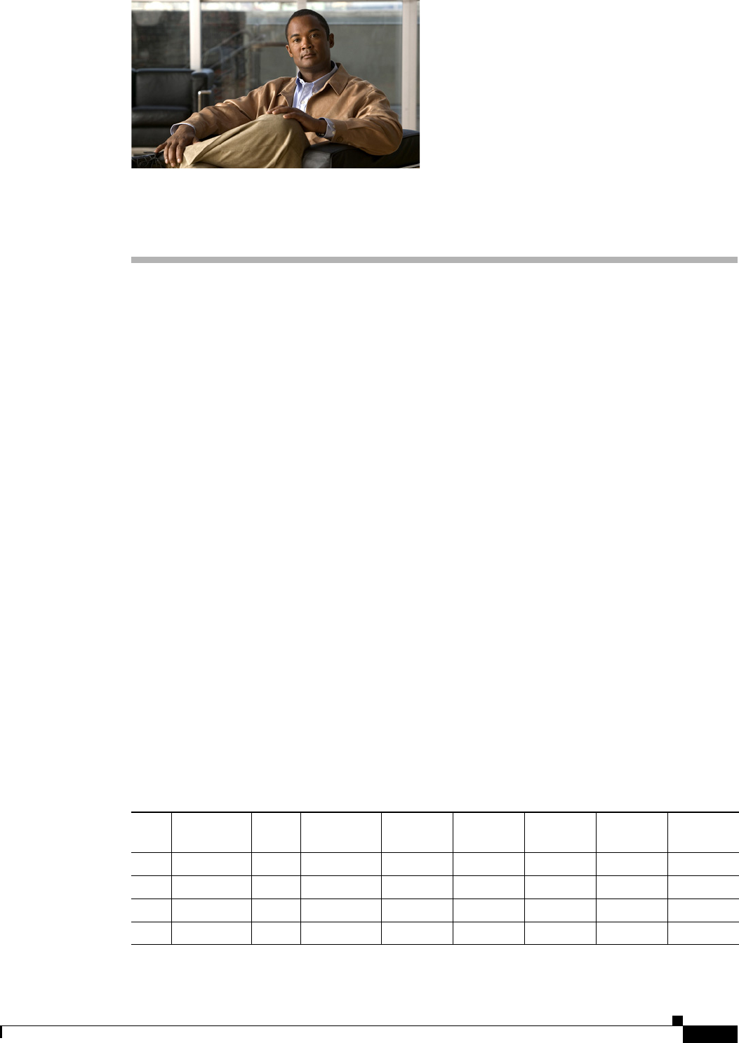
DEC. 2011—EFT REVIEW DRAFT—CISCO CONFIDENTIAL
A-1
Cisco 1240 Connected Grid Router Hardware Installation Guide
OL-26223-01
APPENDIX
A
Connector and Cable Specifications
This appendix includes specifications for the Cisco 1240 Connected Grid Router connectors, adapters,
and compatible cables, and is organized into the following sections:
• Connector Specifications, page A-1
• Cable and Adapter Specifications, page A-8
Connector Specifications
• GPS Serial Port, page A-1
• Alarm Ports, page A-2
• Console Port, page A-2
• Serial Port, page A-4
• AC Power Supply Connector, page A-4
• AC Power Supply Output Connector, page A-5
• Battery Backup Unit Cable Connector, page A-5
• Non-Cisco Module Power Connector, page A-6
• Connected Grid Module Slots, page A-6
GPS Serial Port
For detailed information about the integrated GPS, see the chapter Router Hardware Description.
Table A-1 GPS Serial Port Specification
Port Direction Pin Protocol Baud rate Data bits Parity Stop bits
Flow
control
ATXD-A 23 TSIP-Out 38.4 Kobe 8None 1No
RXD-A 21 TSIP-In 38.4 Kb 8None 1No
BTXD-B 24 NMEA-Out 4800 8None 1No
RXD-B 20 NMEA-In 4800 8None 1No
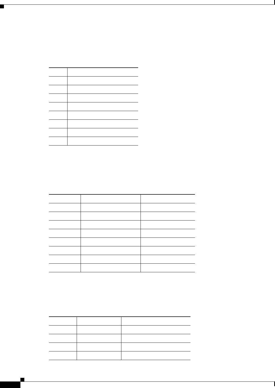
DEC. 2011—EFT REVIEW DRAFT—CISCO CONFIDENTIAL
A-2
Cisco 1240 Connected Grid Router Hardware Installation Guide
OL-26223-01
Appendix A Connector and Cable Specifications
Connector Specifications
Alarm Ports
For detailed information about the alarm ports, see the chapter Router Hardware Description.
Console Port
For detailed information about the console port, see the chapter Router Hardware Description.
Copper Interface—Combination Port (SFP and GE Ethernet)
For detailed information about the combination ports, see the chapter Router Hardware Description.
Table A-2 Alarm Port Specification
Pin Signal Description
1Alarm1_IN
2Alarm2_IN
3Alarm1_OUT_NC
4Alarm2_OUT_NC
5Alarm2_OUT_NO
6Alarm1_OUT_NO
7Alarm_OUT_Common
8Alarm_IN_Common
Table A-3 Console/Auxiliary Port Specification
Pin Signal Name Signal Description
1RTS Output
2DTR Output
3TXD Output
4GND –
5GND –
6RXD Input
7DSR/DCD Input
8CTS Input
Table A-4 Combination Port Specification —Copper Interface
Pin 1000Base-T 100Base-TX/10Base-T
1TX A+ TX DATA+
2TX A- TX DATA-
3RX B+ RX DATA+
4TX C+ N/C

DEC. 2011—EFT REVIEW DRAFT—CISCO CONFIDENTIAL
A-3
Cisco 1240 Connected Grid Router Hardware Installation Guide
OL-26223-01
Appendix A Connector and Cable Specifications
Connector Specifications
SFP Interface—Combination Port (SFP and GE Ethernet)
For detailed information about the combination ports, see the chapter Router Hardware Description.
5TX C- N/C
6RX B- RX DATA-
7RX D+ N/C
8RX D- N/C
Table A-4 Combination Port Specification —Copper Interface (continued)
Pin 1000Base-T 100Base-TX/10Base-T
Table A-5 SFP Port Specification
Pin Signal Name Input/Output Signal Description
1VeeT –GND
2TxFault Output Connects to GPIO
3TxDisable Input Driven from GPIO
4MOD-DEF(2) Bidir Bidirectional. Connects to I2C data
5MOD-DEF(1) Input Connects to I2C Clock
6MOD-DEF(0) Output Grounded in SFP, indicates SFP is present
7Rate Select1
1. Rate Select is an optional SFP input that controls receiver bandwidth when used with Fibre Channel applications.
This pin is unconnected.
– –
8LOS Output Connects to GPIO
9VeeR –GND
10 VeeR –GND
11 VeeR –GND
12 RD- Output Connects to PHY
13 RD+ Output Connects to PHY
14 VeeR –Gnd
15 VccR –3.3V
16 VccT –3.3V
17 VeeT –GND
18 TD+ Input Driven from PHY
19 TD- Input Driven from PHY
20 VeeT –GND
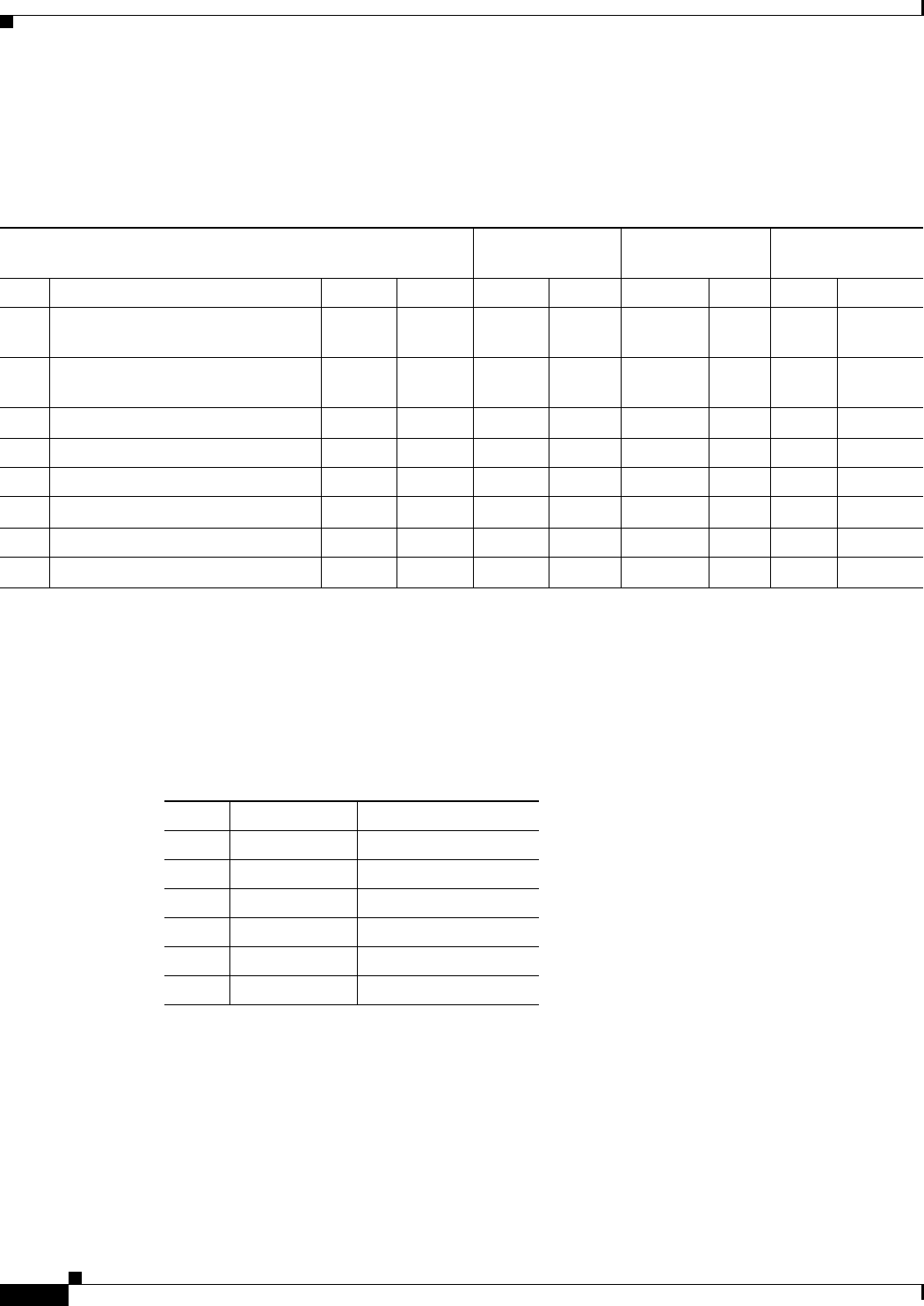
DEC. 2011—EFT REVIEW DRAFT—CISCO CONFIDENTIAL
A-4
Cisco 1240 Connected Grid Router Hardware Installation Guide
OL-26223-01
Appendix A Connector and Cable Specifications
Connector Specifications
Serial Port
For detailed information about the combination ports, see the chapter Router Hardware Description.
AC Power Supply Connector
For detailed information about the hardware described in this section, the chapter Router Hardware
Description.
Table A-6 Serial Port Specification
RS-2321
1. The RS232 pinouts use the EIA-561 standard.
RS-485 Full
Duplex
RS-485 Half
Duplex Ethernet
Pin Signal Description (Abbreviation) DTE DCE Signal Dir Signal Dir 10/100 10000
1DCE ready, ring indicator
(DSR/RI)
<— —> – – – – RX+ TX/RX1+
2Received line signal detector
(DCD)
<— —> – – – – RX- TX/RX1-
3DTE ready (DTR) —> <— – – – – TX+ TX/RX2+
4Signal ground (COM) ––COM –COM – – TX/RX3+
5Received data (RxD) <— —> TX+ —> TX/RX+ <—> –TX/RX3-
6Transmitted data (TxD) —> <— RX+ <— – – TX- TX/RX2-
7Clear to send (CTS) <— —> RX- —> TX/RX- <—> –TX/RX4+
8Request to send (RTS) —> <— TX- <— – – – TX/RX4-
Table A-7 AC Power Supply Connector Specification
Pin Signal Name Signal Description
1 L AC line
2 N AC neutral
3Chassis Chassis ground
4NC –
5NC –
6NC –
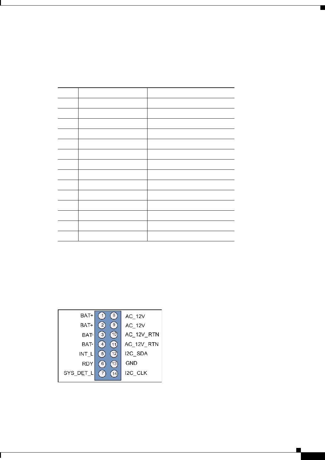
DEC. 2011—EFT REVIEW DRAFT—CISCO CONFIDENTIAL
A-5
Cisco 1240 Connected Grid Router Hardware Installation Guide
OL-26223-01
Appendix A Connector and Cable Specifications
Connector Specifications
AC Power Supply Output Connector
For detailed information about the hardware described in this section, the chapter Router Hardware
Description.
Battery Backup Unit Cable Connector
For detailed information about the hardware described in this section, see the chapter Installing Battery
Backup Units.
Figure A-1 Battery Backup Unit Cable Connector Pinouts
Table A-8 AC Power Supply Output Connector Specification
Pin Signal Name Signal Description
112V 12V source
212V 12V source
33.3V_STBY 3.3V source
4OUT_EN_L 12V output enable
5PS_PRESENT_L Power supply presence
6I2C_SDA I2C data
712C_CLK 12C clock
8GND 12V return
9GND 12V return
10 GND 3.3V standby return
11 L2_OK AC Phase 1 input good
12 NC –
13 DC_OUT_OK 12V output good
14 ALRT Power supply fault
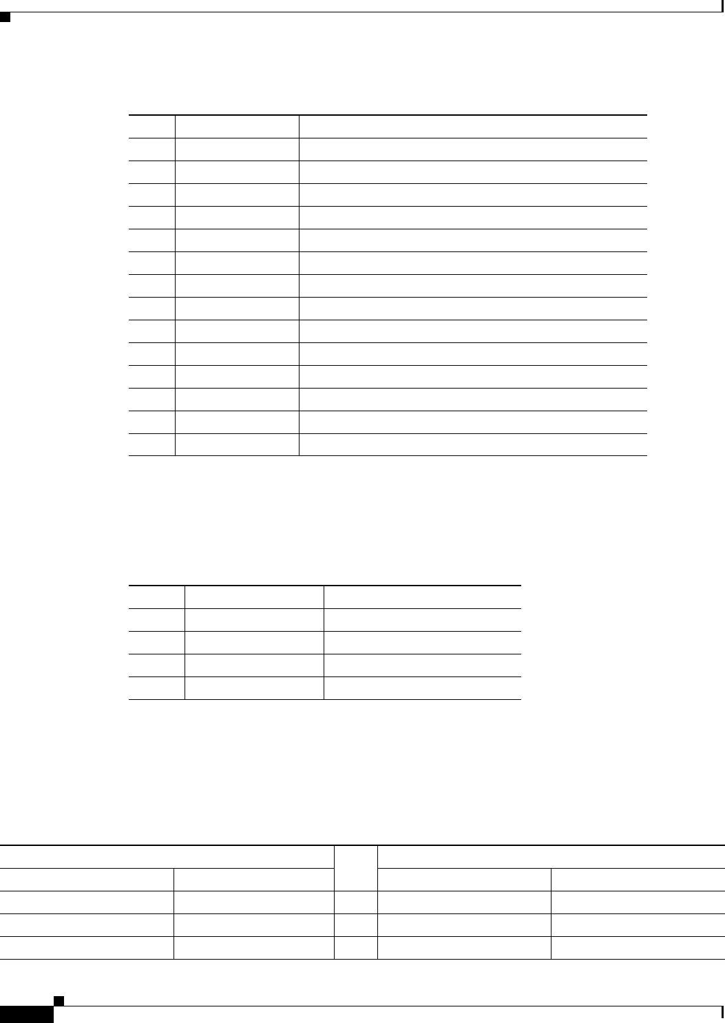
DEC. 2011—EFT REVIEW DRAFT—CISCO CONFIDENTIAL
A-6
Cisco 1240 Connected Grid Router Hardware Installation Guide
OL-26223-01
Appendix A Connector and Cable Specifications
Connector Specifications
Non-Cisco Module Power Connector
For more information about non-Cisco modules, see the chapter Installing Non-Cisco Modules.
Connected Grid Module Slots
For detailed information about the hardware described in this section, see the the Connected Grid
modules documentation on Cisco.com.
Table A-9 Battery Backup Unit Cable Connector Specification
Pin Signal Name Signal Description
1BAT_12V +12V output
2BAT_12V +12V output
3BAT_12VRTN Ground
4BAT_12VRTN Ground
5INT_L BBU interrupt
6RDY MCU indicates good status and 12C communication ready
7SYS_DET_L Loop back for cable interlock
8AC_12V +12V input
9AC_12V +12V input
10 AC_12VRTN Ground
11 AC_12VRTN Ground
12 12C Data +3.3V +/- 2%
13 Gnd Ground
14 12C Clock +3.3V +/- 2%
Table A-10 Micro-Fit 3.0 Power Connector Specification
Pin Signal Name Signal Description
112V 12V from system
2GND System GND
3CBL_PRESENT:L Cable presence detect
4GND System GND
Table A-11 Connected Grid Module Slots Specification
Side A Signal
Pin
Side B Signal
Name Description Name Description
BRD_PRSNT_A BRD_PRSNT_A 1GND GND
GND GND 2GPIO signals MIM_GPIO_0
3.3V Standby 3.3V Rail 3GND GND

DEC. 2011—EFT REVIEW DRAFT—CISCO CONFIDENTIAL
A-7
Cisco 1240 Connected Grid Router Hardware Installation Guide
OL-26223-01
Appendix A Connector and Cable Specifications
Connector Specifications
GND GND 4GPIO signals MIM_GPIO_1
12V DC Input 12V 5GND GND
12V DC Input 12V 6GPIO signals MIM_GPIO_2
GND GND 7GPIO signals MIM_GPIO_3
MIM_GPIO_4 GPIO signals 8GND GND
GND GND 9GPIO signals MIM_GPIO_5
Reset_L Reset/Watchdog Reset 10 GPIO signals MIM_GPIO_6
PWR_OK Power OK 11 GPIO signals MIM_GPIO_7
Connector Notch
GND GND 12 GND GND
GND GND 13 Power enable PWR_EN_L
USB_HOST_DN USB host diff bus 14 AC power ok indicator from
MB
AC pwr ok (1)
USB_HOST_DP USB host diff bus 15 DC-DC regulator input
power ok
12v pwr ok (1)
GND GND 16 GND GND
GND GND 17 SPI data dut (18.75M) SPI_MOSI (RXD)
SPI_SCK (TXD) SPI clock (RTS) 18 SPI_CS SPI_SSN (CTS)
GND GND 19 SPI Data in (18.75M) SPI_MISO (TXD)
GND GND 20 GND GND
GE_TX_N GE transmit signal 21 I2C clock (400kHz) SCLK
GE_TX_P GE transmit signal 22 GND GND
GND GND 23 I2C Data in/out SDA
GND GND 24 Reset QUACK_RST_L
GE_RX_N GE receive signal 25 GND GND
GE_RX_P GE receive signal 26 GPIO serial clock GPIO_SCK
GND GND 27 GND GND
GND GND 28 GPIO Serial data in GPIO_MISO
PCIe_PET_N PCIe transmit diff pair 29 GPIO Serial data out GPIO_MOSI
PCIe_PEN_P PCIe transmit diff pair 30 GPIO Serial enable GPIO_SEN
GND GND 31 GND GND
GND GND 32 Board ready BRD_RDY
PCIe_PER_N PCIe receive diff pair 33 3.3V from PS 3.3V/RESERVED
PCIe_PER_P PCIe receive diff pair 34 GND GND
GND GND 35 RESERVED RESERVED
GND GND 36 RESERVED RESERVED
Table A-11 Connected Grid Module Slots Specification (continued)
Side A Signal
Pin
Side B Signal
Name Description Name Description
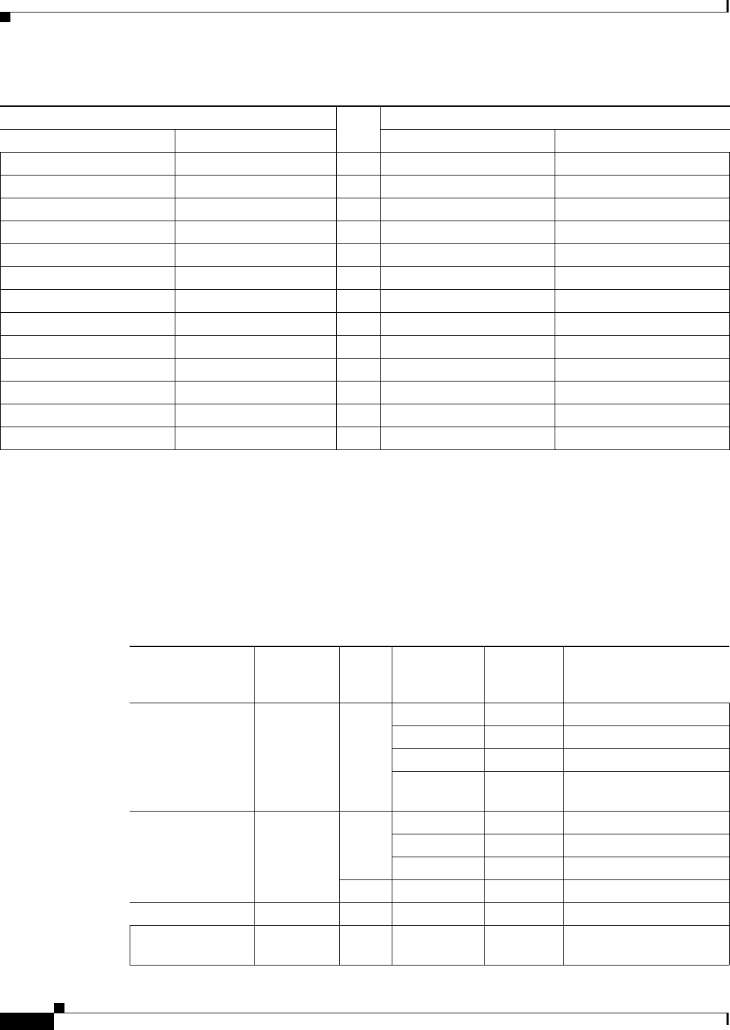
DEC. 2011—EFT REVIEW DRAFT—CISCO CONFIDENTIAL
A-8
Cisco 1240 Connected Grid Router Hardware Installation Guide
OL-26223-01
Appendix A Connector and Cable Specifications
Cable and Adapter Specifications
Cable and Adapter Specifications
SFP Cable
For detailed information about the SPF ports, see the chapter Router Hardware Description.
PCIe_CLKIN_N PCIe clock diff pair 37 RESERVED RESERVED
PCIe_CLKIN_P PCIe clock diff pair 38 RESERVED RESERVED
GND GND 39 RESERVED RESERVED
GND GND 40 RESERVED RESERVED
RESERVED RESERVED 41 GND GND
RESERVED RESERVED 42 JTAG Clock TCK
GND GND 43 JTAG Data Out TDO
GND GND 44 JTAG Mode Select TMS
RESERVED RESERVED 45 GND GND
RESERVED RESERVED 46 JTAG Data In TDI
GND GND 47 JTAG Reset TRSTN
GND GND 48 GND GND
RESERVED RESERVED 49 BRD_PRSNT_B BRD PRSNT B
Table A-11 Connected Grid Module Slots Specification (continued)
Side A Signal
Pin
Side B Signal
Name Description Name Description
Table A-12 SFP Port Cabling Specification
SFP Module
Wavelength
(nm)
Cable
Type
Core size/
Cladding Size
(micron)
Modal
Bandwidth
(MHz/km) Cable Distance
1000BASE-SX 850 MMF 62.5/125 160 722 feet (220 m)
62.5/125 200 902 feet (275 m)
50/125 400 1640 feet (500 m)
50/125 500 1804 feet (550 m)
3281 ft (1000 m)
1000BASE-LX/LH 1310 MMF162.5/125 500 1804 feet (550 m)
50/125 400 1804 feet (550 m)
50/125 500 1804 feet (550 m)
SMF G.6522 —32,808 feet (10,000 km)
1000BASE-EX 1310 SMF — — 131,234 feet (40,000 km)
1000BASE-ZX 1550 SMF G.6522—43.4 to 62 miles
(70 to 100 km)2

DEC. 2011—EFT REVIEW DRAFT—CISCO CONFIDENTIAL
A-9
Cisco 1240 Connected Grid Router Hardware Installation Guide
OL-26223-01
Appendix A Connector and Cable Specifications
Cable and Adapter Specifications
1000BASE-BX-U 1310 SMF — — 32,808 ft (10,000 m)
1000BASE-BS-D 1490 SMF — — 32,808 ft (10,000 m)
1. A mode-conditioning patch cord is required. Using an ordinary patch cord with MMF or 1000BASE-LX/LH SFP modules
and a short link distance can cause transceiver saturation and an elevated bit error rate (BER). When using the LX/LH SFP
module with 62.5-micron diameter MMF, you must also install a mode-conditioning patch cord between the SFP module and
the MMF cable on both the sending and receiving ends of the link. The mode-conditioning patch cord is required for link
distances greater than 984 feet (300 m).
2. 1000BASE-ZX SFP modules can send data up to 62 miles (100 km) by using dispersion-shifted SMF or low-attenuation SMF;
the distance depends on the fiber quality, the number of splices, and the connectors.
Table A-12 SFP Port Cabling Specification (continued)
SFP Module
Wavelength
(nm)
Cable
Type
Core size/
Cladding Size
(micron)
Modal
Bandwidth
(MHz/km) Cable Distance

DEC. 2011—EFT REVIEW DRAFT—CISCO CONFIDENTIAL
A-10
Cisco 1240 Connected Grid Router Hardware Installation Guide
OL-26223-01
Appendix A Connector and Cable Specifications
Cable and Adapter Specifications
DEC. 2011—EFT REVIEW DRAFT—CISCO CONFIDENTIAL
B-1
Cisco 1240 Connected Grid Router Hardware Installation Guide
OL-26223-01
APPENDIX
B
Starting a Router Terminal Session
This appendix describes how to start a terminal session with the Cisco 1240 Connected Grid Router
using the console port. Start a terminal session with the router when you are at the router installation
location and want to administer the router with a direct connection using the command-line interface
(CLI) software.
Before You Begin
Before you start a terminal session with the router, you must connect a PC or PC terminal to the router
console port following the instructions in Connecting the Console Port, page 6-15 in the chapter
Installing the Router.
About the Console Port
Caution The console port does not support cable glands. When a cable is connected to this port, the router interior
is exposed to environmental elements, which can damage the port and the router interior. This port
should be exposed only during terminal sessions, when a cable is connected to the port. This port should
never be left unattended when in use.
The console port is an asynchronous serial port that allows you to connect to the device for initial
configuration through a standard RS-232 port with an RJ-45 connector. Any device connected to this
port must be capable of asynchronous transmission.
Console Port Settings
Configure the following parameters for the console port:
Parameter Console Port Setting Description
Baud 9600 Specifies the transmission speed for the connection.
Data bits 8Specifies the number of bits in an 8-bit byte that is used for data.

DEC. 2011—EFT REVIEW DRAFT—CISCO CONFIDENTIAL
B-2
Cisco 1240 Connected Grid Router Hardware Installation Guide
OL-26223-01
Appendix B Starting a Router Terminal Session
Connecting to the Console Port with Microsoft Windows
Using the Ctrl-C Command
The router console port is located on the router exterior and is accessible by removing the seal over the
console port. (For details, see Console Port, page 2-15 in the chapter Router Hardware Description.)
On many Cisco routers, you can enter Ctrl-C to interrupt the router startup process and then delete or
change the admin password, or view or delete the router configuration.
To prevent unauthorized access to the router configurations and passwords, the Ctrl-C command is
disabled on the Cisco CGR 1240 Router while it is booting up and loading the system software.
Connecting to the Console Port with Microsoft Windows
This section describes how to connect to the router console port using Microsoft Windows.
Step 1 Start a terminal emulator application, such as Windows HyperTerminal (included with some versions of
Windows OS) or PuTTY.
Step 2 Configure the terminal emulation software with the parameters described in About the Console Port,
page B-1.
Step 3 Connect to the router.
Connecting to the Console Port with Mac OS X
This procedure describes how to connect a Mac OS X system USB port to the console using the built-in
OS X Terminal utility.
Step 1 Use the Finder to go to Applications > Utilities > Terminal.
Step 2 Connect the OS X USB port to the router.
Step 3 Enter the following commands to find the OS X USB port number:
macbook:user$ cd /dev
macbook:user$ ls -ltr /dev/*usb*
crw-rw-rw- 1 root wheel 9, 66 Apr 1 16:46 tty.usbmodem1a21
DT-macbook:dev user$
Step 4 Connect to the USB port with the following command followed by the router USB port speed:
macbook:user$ screen /dev/tty.usbmodem1a21 9600
Parity None Specifies the odd or even parity for error detection.
Stop bits 1Specifies the stop bits for an asynchronous line.
Parameter Console Port Setting Description

DEC. 2011—EFT REVIEW DRAFT—CISCO CONFIDENTIAL
B-3
Cisco 1240 Connected Grid Router Hardware Installation Guide
OL-26223-01
Appendix B Starting a Router Terminal Session
Connecting to the Console Port with Linux
To Disconnect the OS X USB Console from the Terminal Window
Enter Ctrl+A followed by Ctrl+\
Connecting to the Console Port with Linux
This procedure shows how to connect a Linux system USB port to the console using the built-in Linux
Terminal utility.
Step 1 Open the Linux Terminal window.
Step 2 Connect the Linux USB port to the router.
Step 3 Enter the following commands to find the Linux USB port number:
root@usb-suse# cd /dev
root@usb-suse /dev# ls -ltr *ACM*
crw-r--r-- 1 root root 188, 0 Jan 14 18:02 ttyACM0
root@usb-suse /dev#
Step 4 Connect to the USB port with the following command followed by the router USB port speed:
root@usb-suse /dev# screen /dev/ttyACM0 9600
To Disconnect the Linux USB Console from the Terminal Window
Enter Ctrl+A followed by :, then type quit.

DEC. 2011—EFT REVIEW DRAFT—CISCO CONFIDENTIAL
B-4
Cisco 1240 Connected Grid Router Hardware Installation Guide
OL-26223-01
Appendix B Starting a Router Terminal Session
Connecting to the Console Port with Linux

DEC. 2011—EFT REVIEW DRAFT—CISCO CONFIDENTIAL
Index
IN-1
Cisco 1240 Connected Grid Router Hardware Installation Guide
OL-26223-01
INDEX
A
AC power supply
connector pinout A-4
output pinout A-5
asynchronous serial baud rates 3-7
auxiliary port
pinout A-2
B
baud rate
asynchronous serial 3-7
C
connections
asynchronous/synchronous serial 3-7
DCE 3-6
DTE 3-6
Ethernet 3-5
network 3-5
serial 3-5
console port
pinout A-2
D
DCE connections 3-6
DTE connections 3-6
E
ESD
damage prevention 3-2
ESD-preventive wrist strap 3-2
Ethernet cable types 3-5
I
installation
tools required 3-7
L
LAN
interface types 3-5
N
network connections 3-5
P
pinouts
AC power supply connector A-6
AC power supply output A-5
auxiliary port A-2
battery backup unit connector A-5
battery connector A-6
console port A-2
third party radio power connector A-6
S
serial connections, considerations 3-5
serial port specifications 3-6
site
requirements 3-3
specifications
serial ports 3-6

DEC. 2011—EFT REVIEW DRAFT—CISCO CONFIDENTIAL
Index
IN-2
Cisco 1240 Connected Grid Router Hardware Installation Guide
OL-26223-01
T
Tables
DTE and DCE devices 3-6
third party radio
power connector pinouts A-6
tools required for installation 3-7
W
Warnings
lightning activity warning 3-3
qualified personnel 3-3
SELV circuit 3-5