Cisco Systems ALTMT0556 Utility Meter Monitoring System User Manual cgr1240hig
Cisco Systems Inc Utility Meter Monitoring System cgr1240hig
Contents
- 1. user manual pt 1
- 2. 3G module manual
- 3. 900 MHz module manual
- 4. user manual pt 2
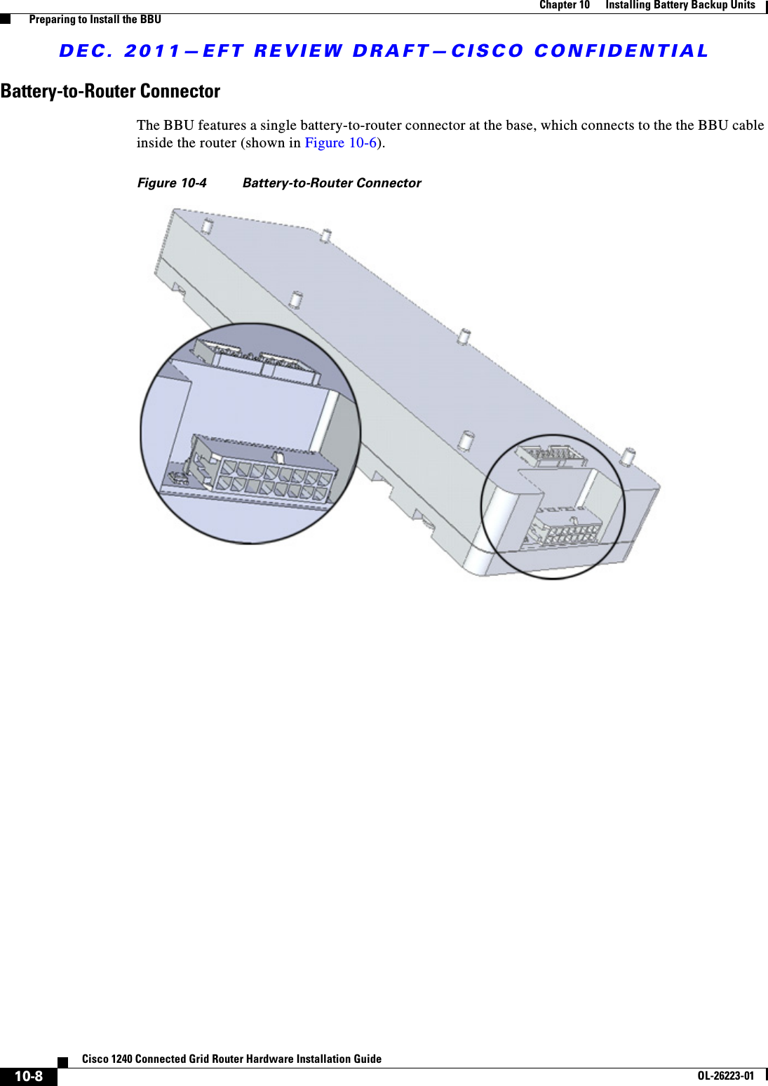
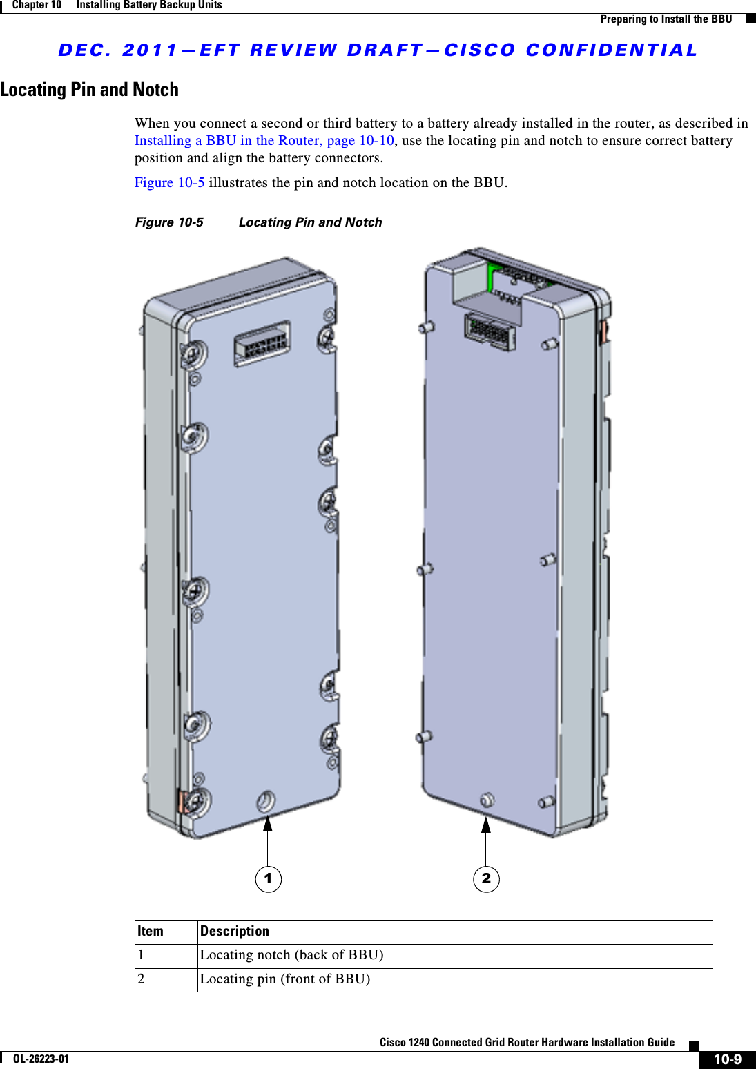
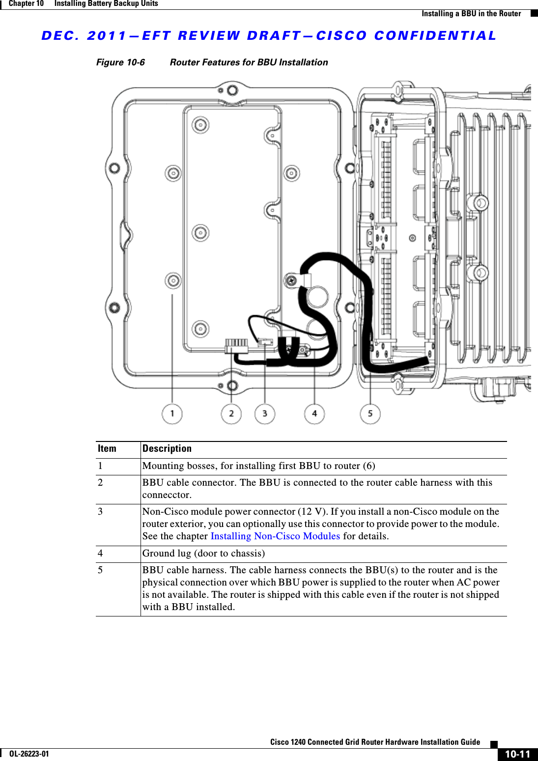
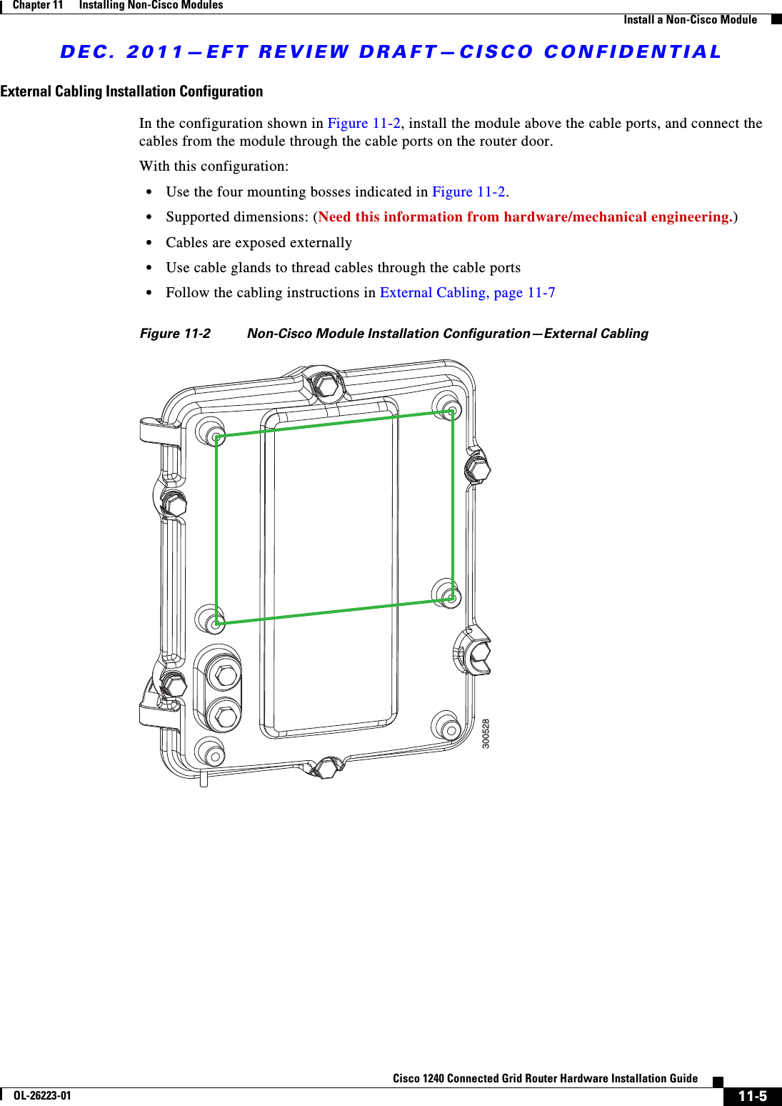
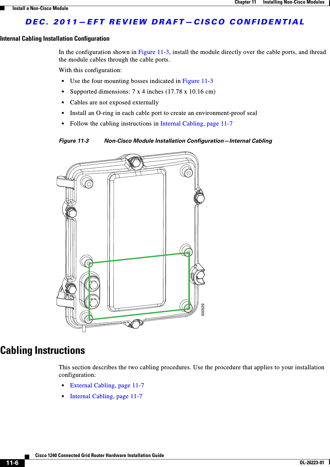
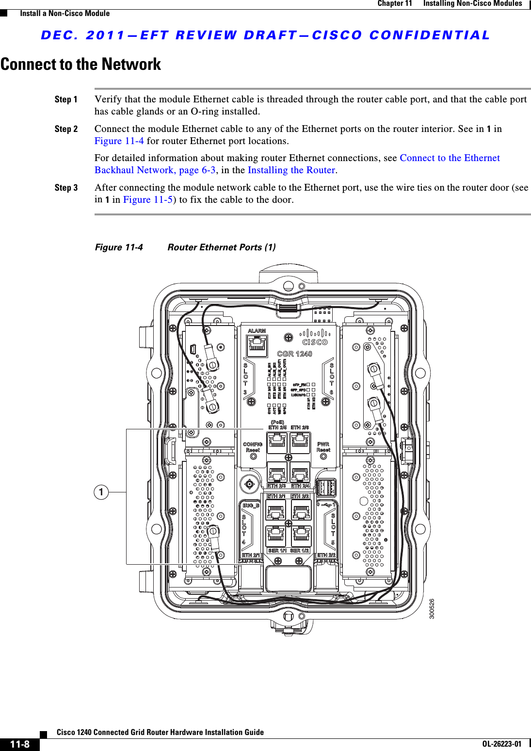
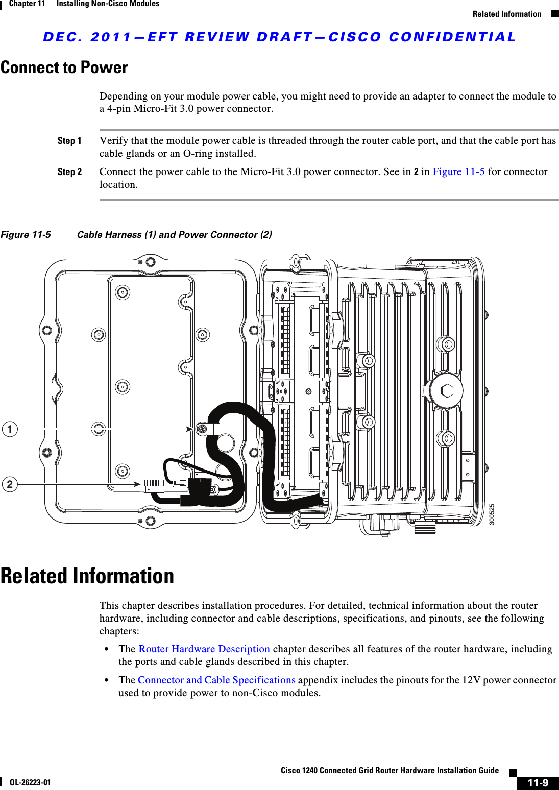
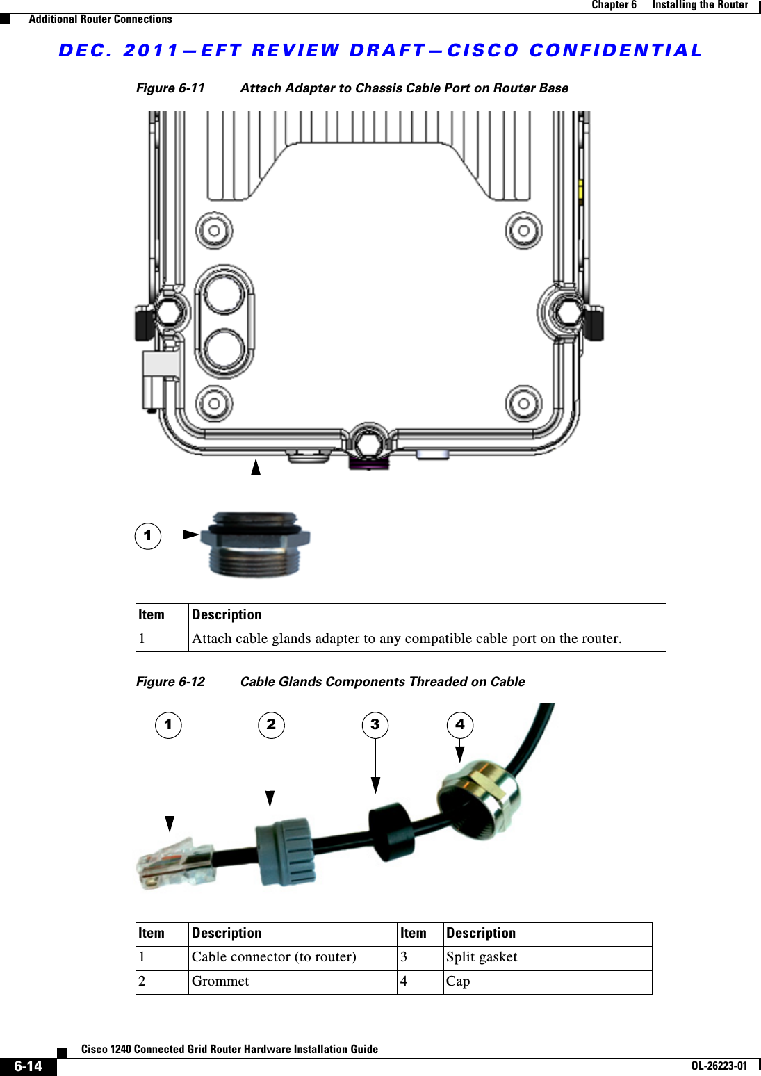
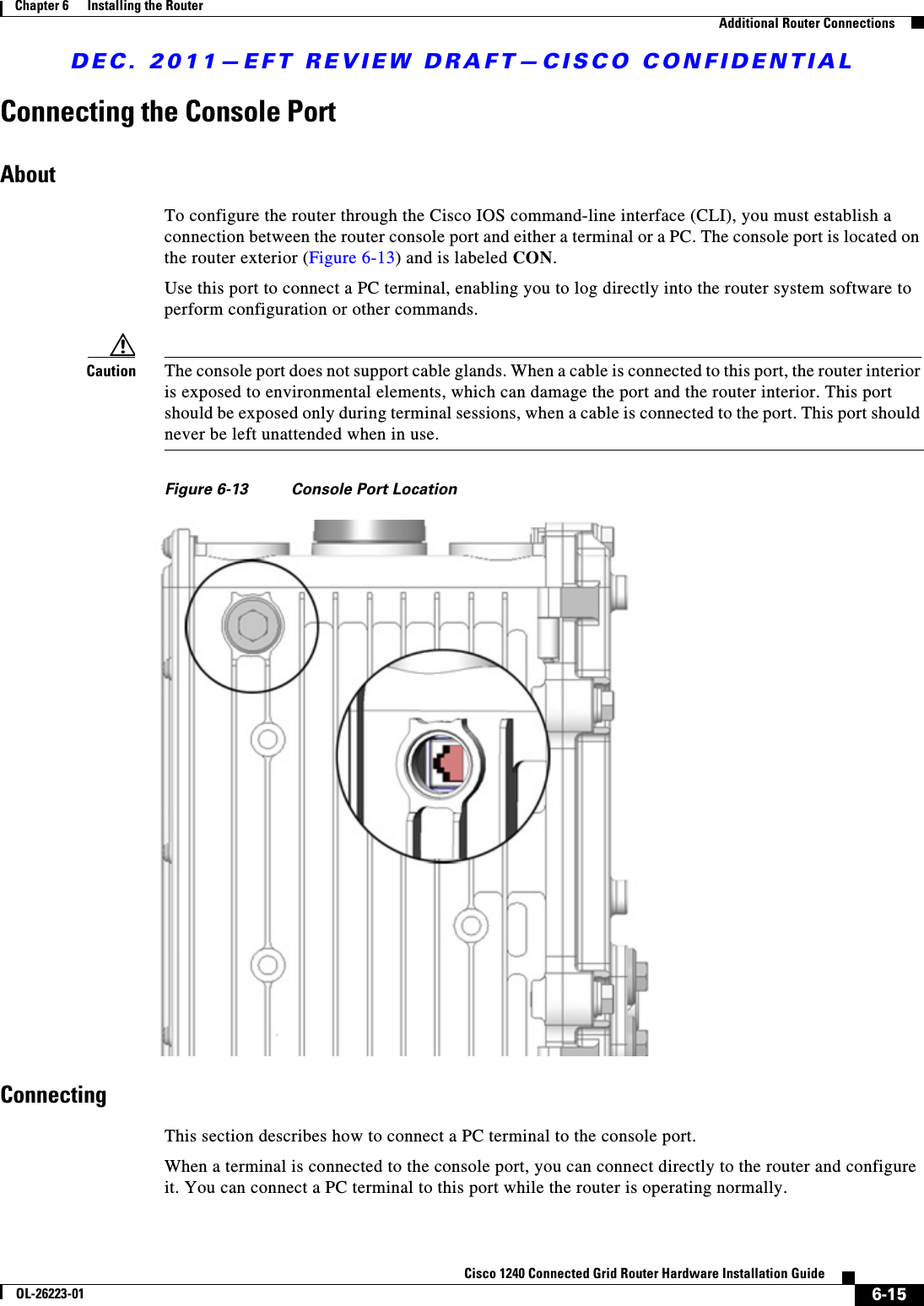
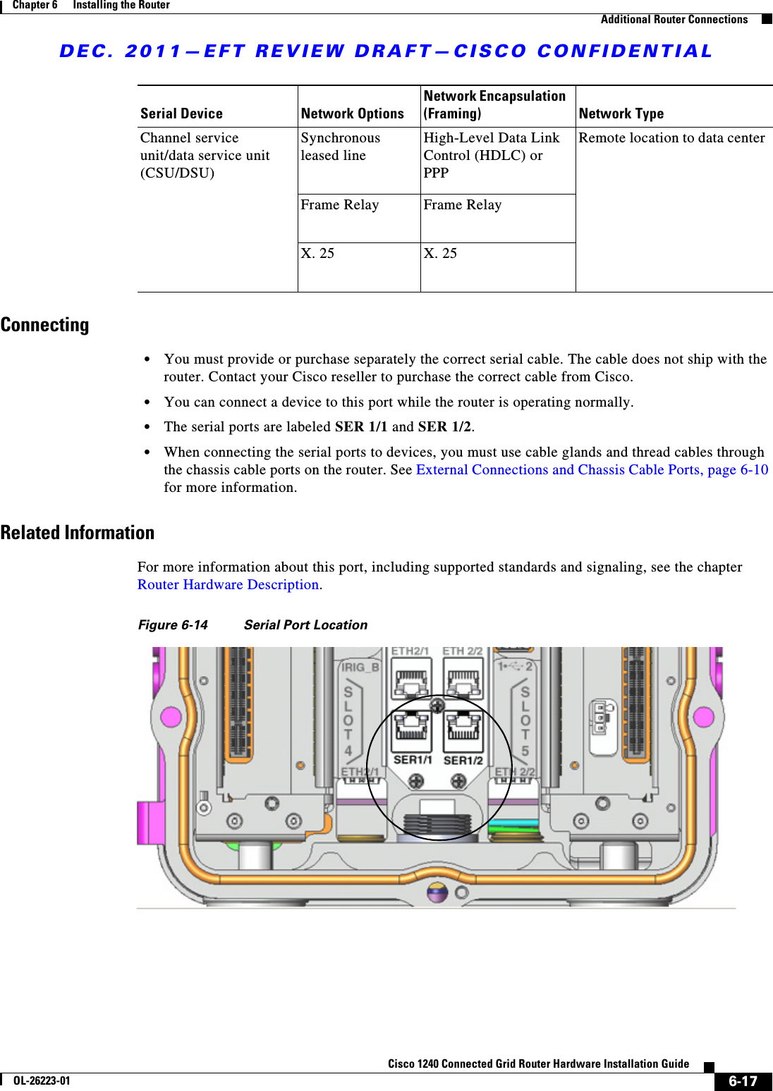
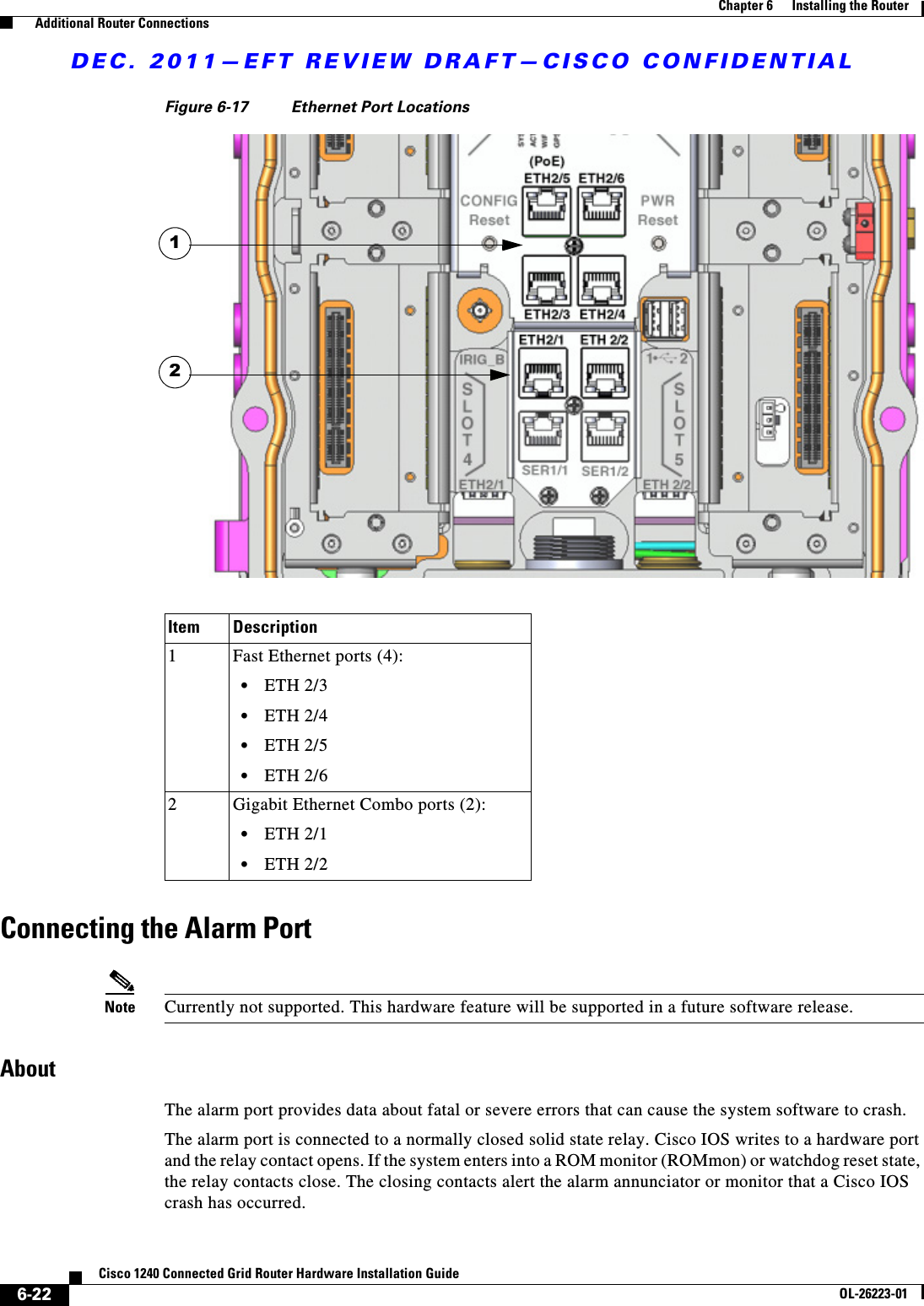
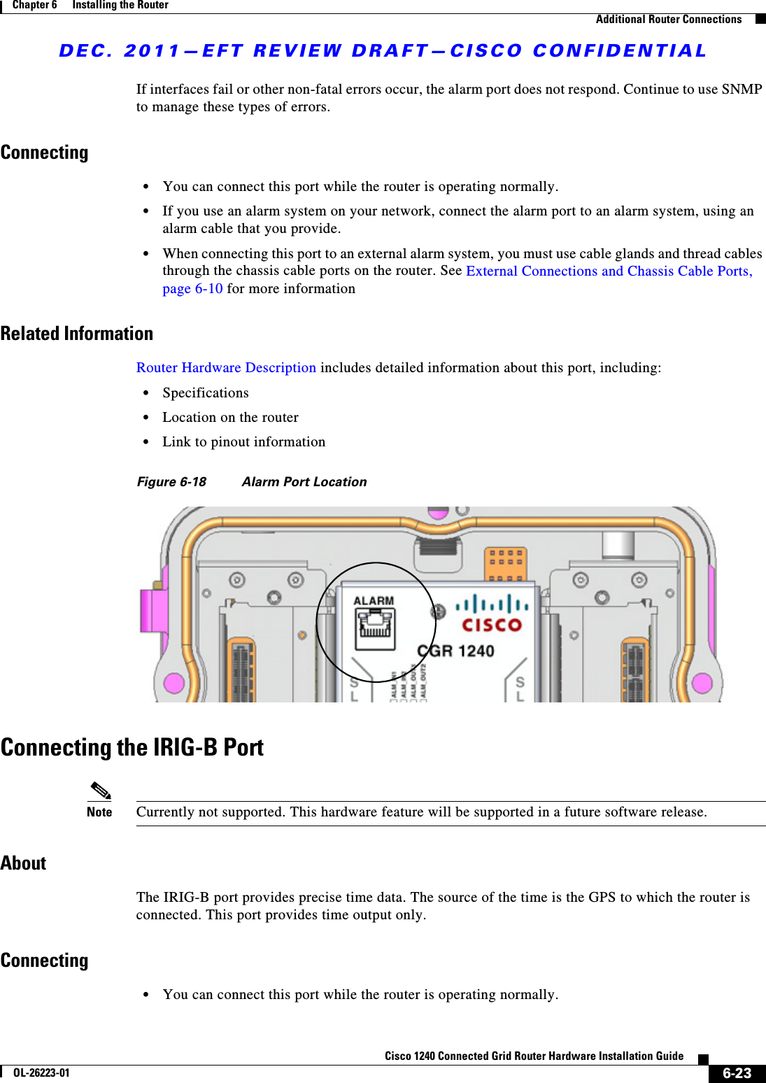
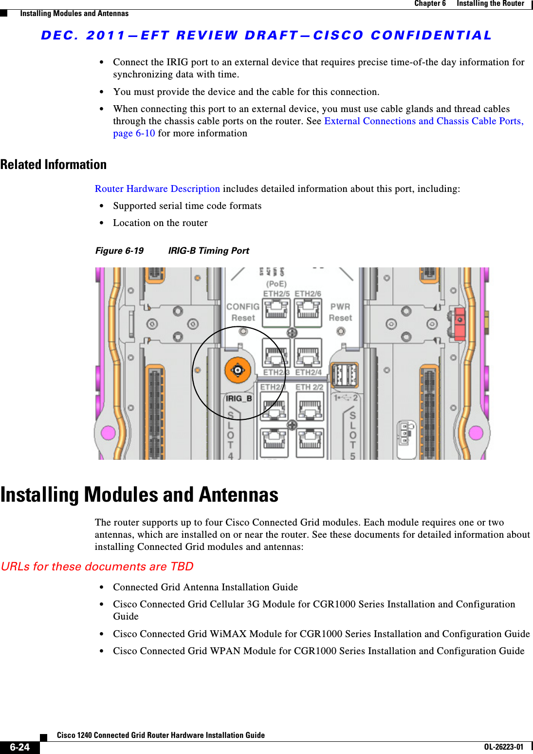
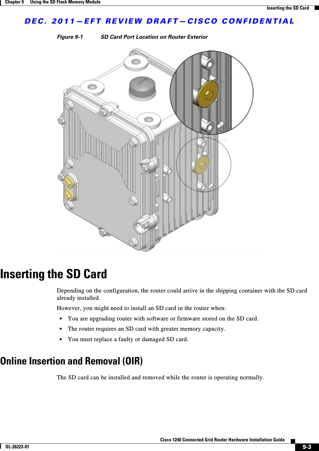
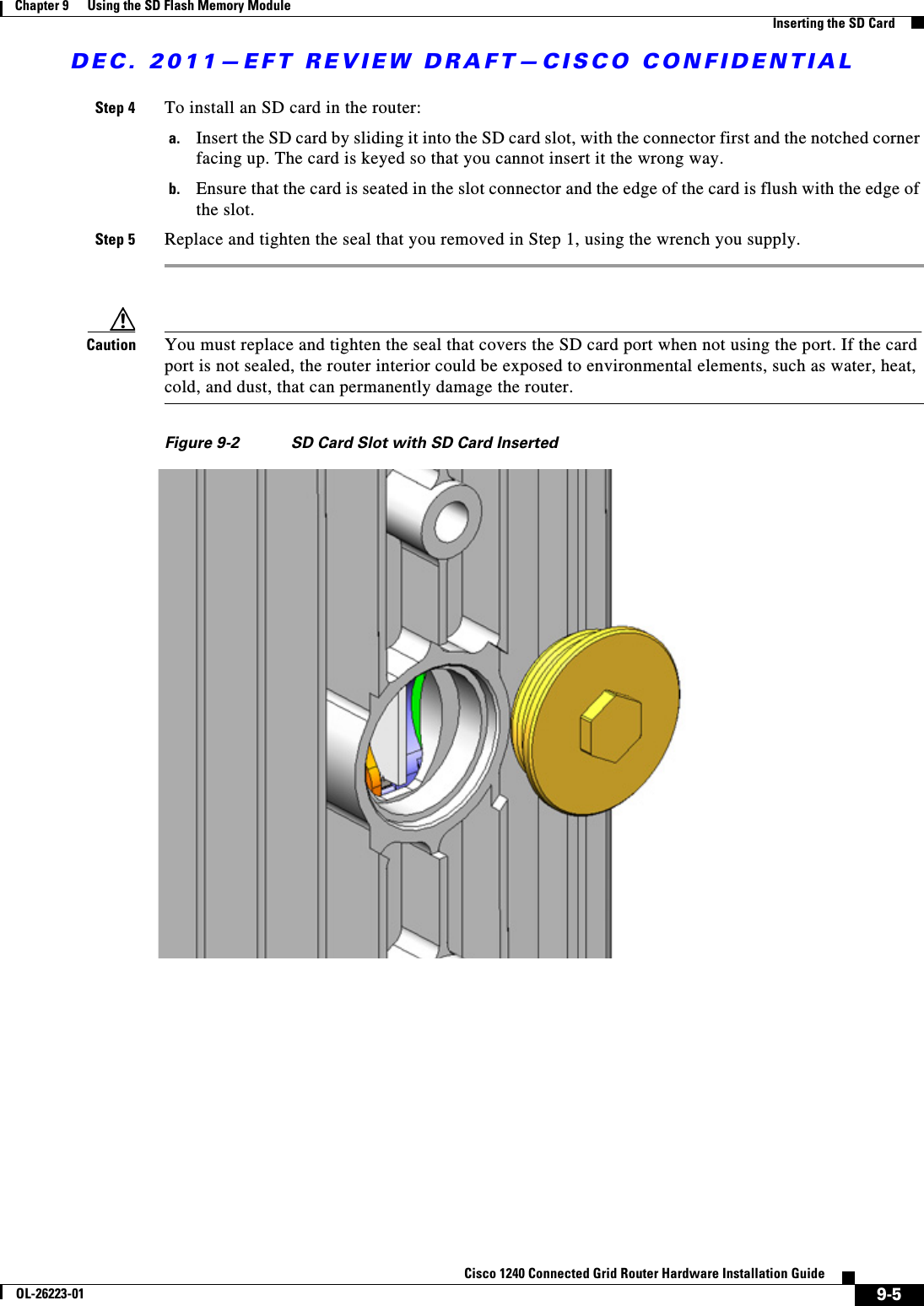
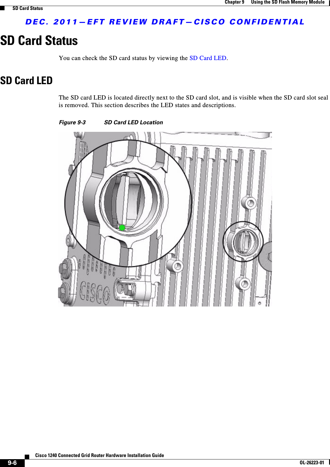
user manual pt 2
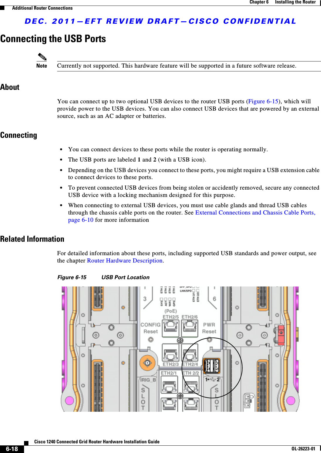
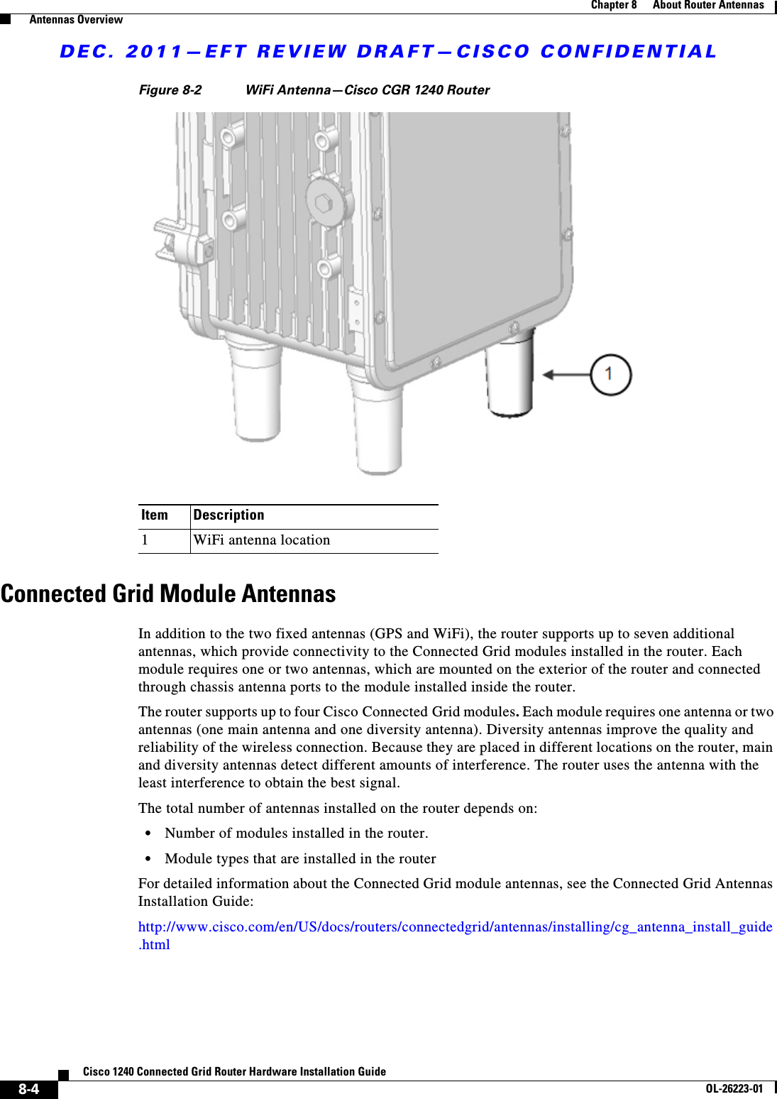

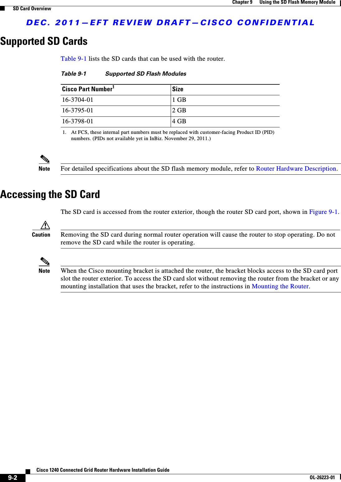
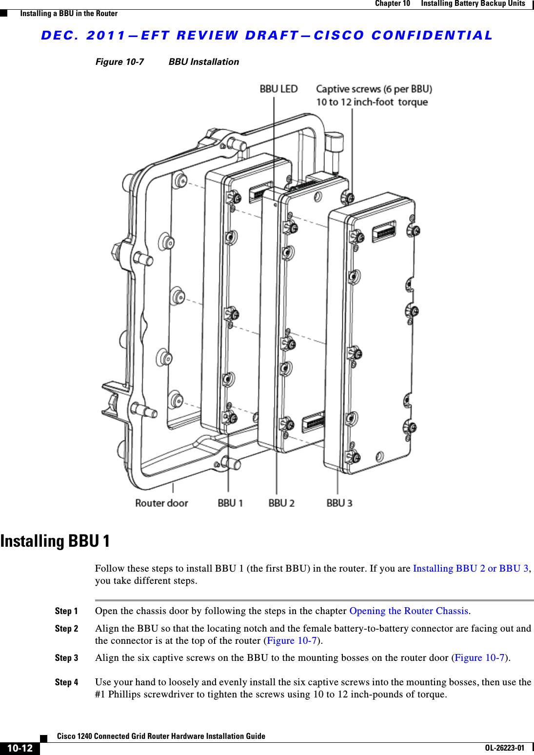
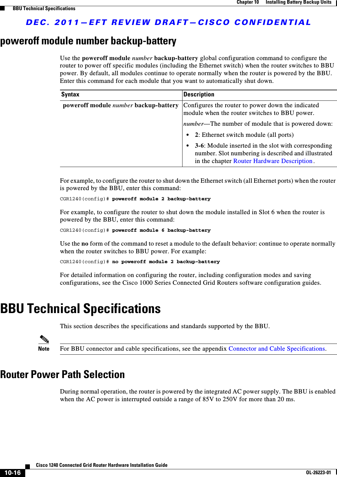
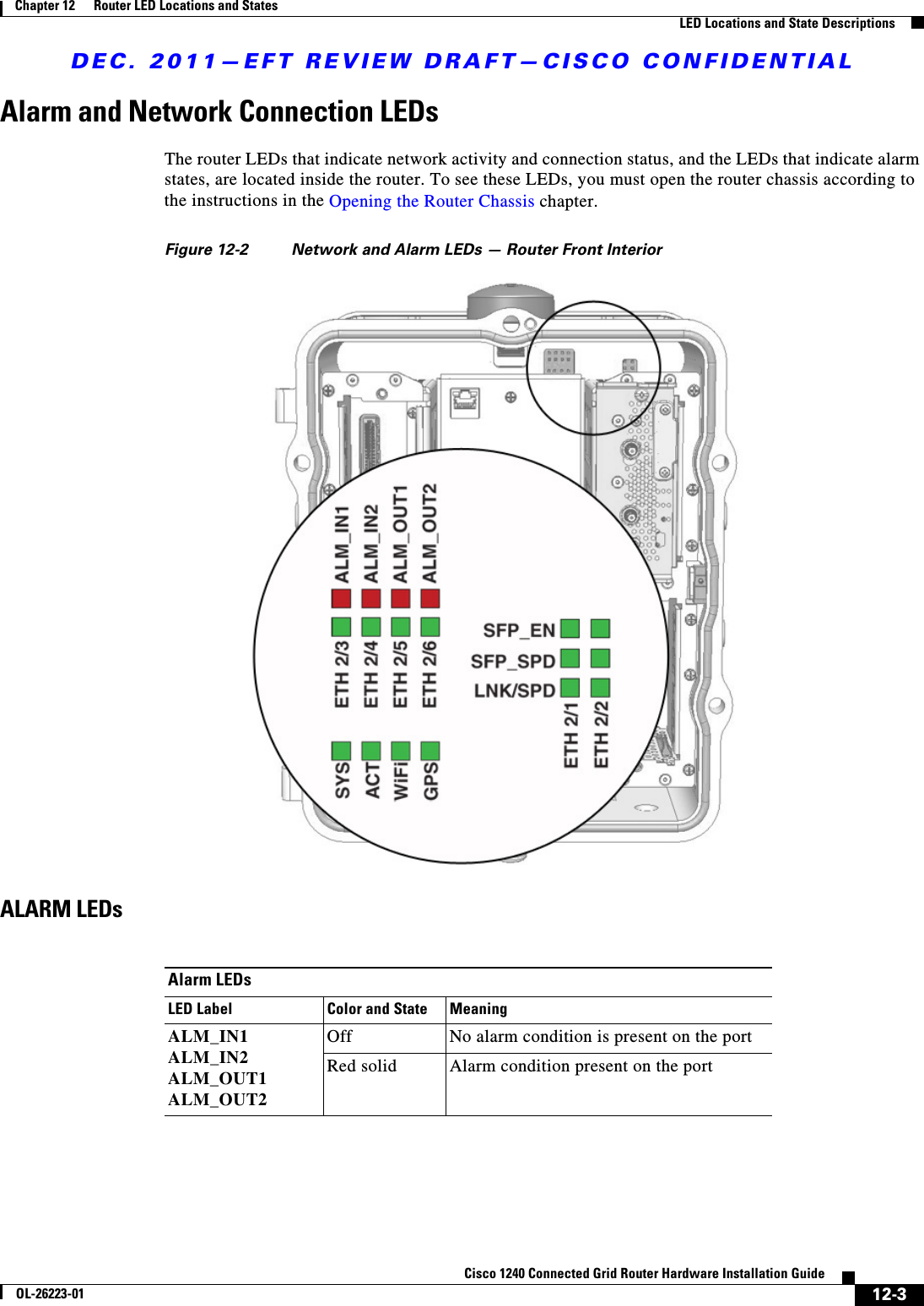
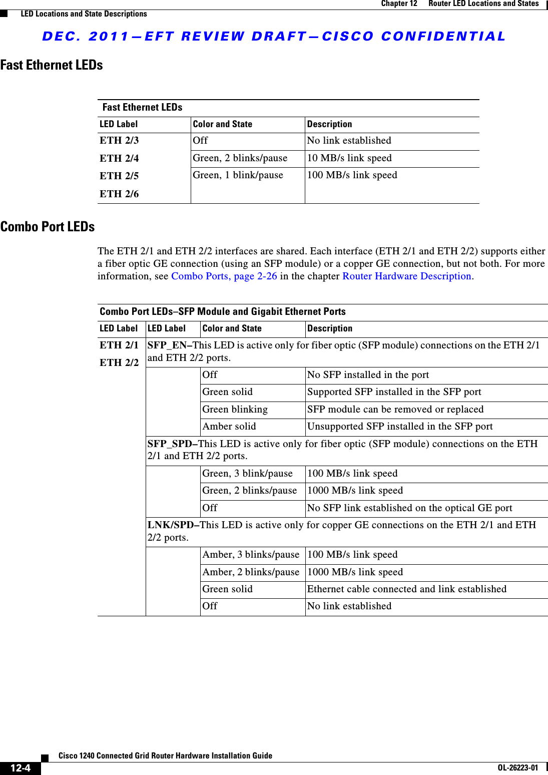
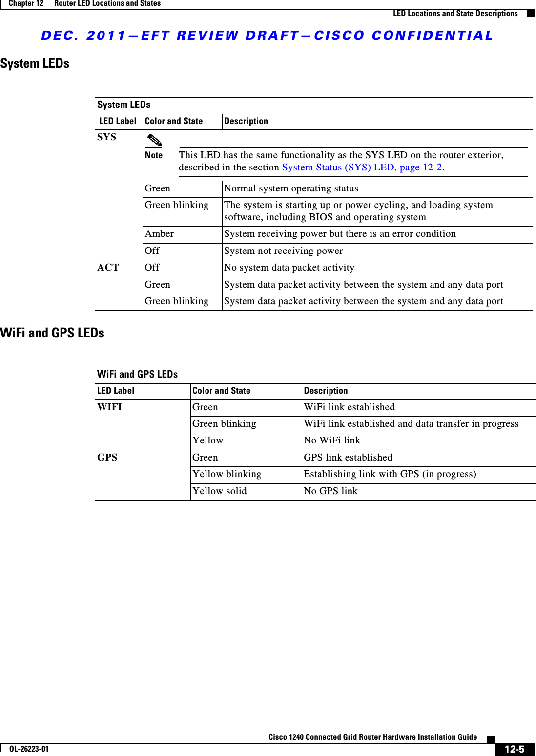
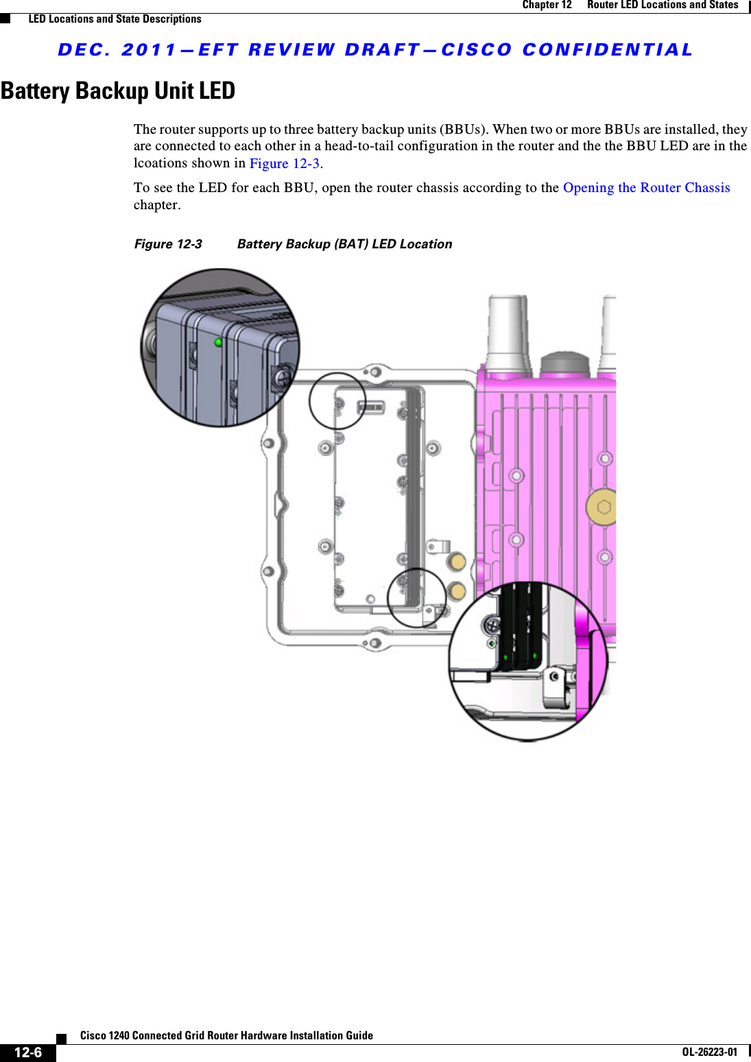
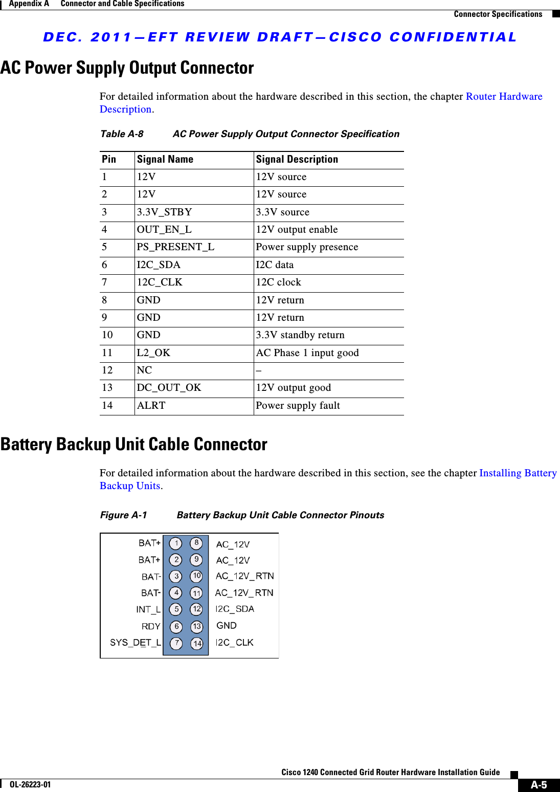
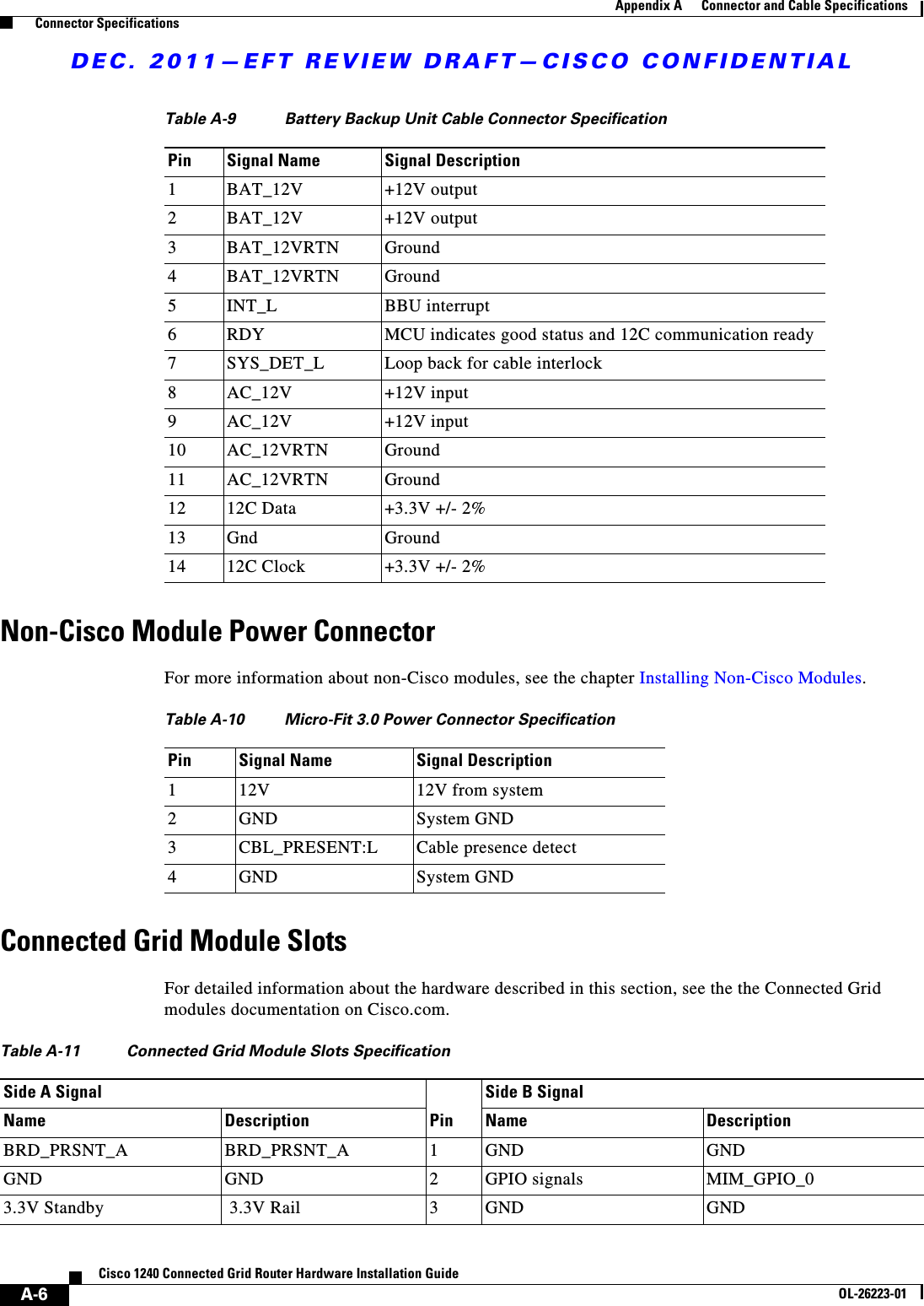
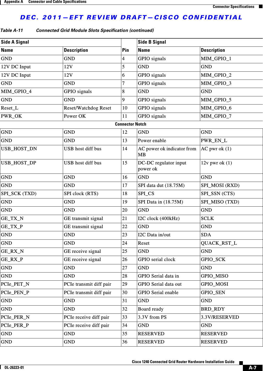
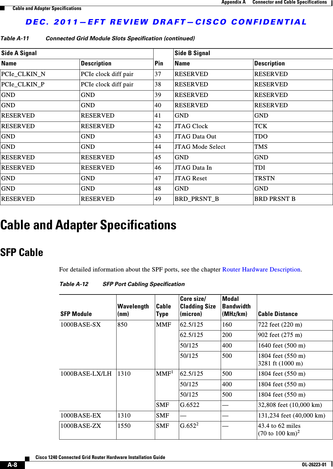
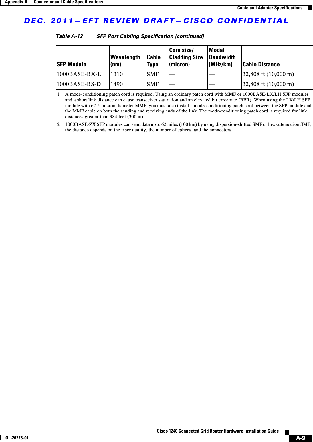
![DEC. 2011—EFT REVIEW DRAFT—CISCO CONFIDENTIAL9-7Cisco 1240 Connected Grid Router Hardware Installation GuideOL-26223-01Chapter 9 Using the SD Flash Memory Module Related CommandsFigure 9-4 SD Flash Memory Module (SD0) LED StatesRelated CommandsUse the copy running-config startup-config command to save the router current software configuration to the SD card:cgr1240# copy running-config startup-config [########################################] 100% Copy complete, now saving to disk (please wait)...Label Description Color and State DescriptionSD0 SD flash card statusGreen solid SD flash card is installed and operating normally.Green blinking A data transfer between the router and the SD card is in progress.Amber solid • An error occurred when the router accessed the SD flash card. • The router could not find a system software image.Amber blinking An unsupported SD card is installed in the slot.Amber flashing No SD card is installed in slot.](https://usermanual.wiki/Cisco-Systems/ALTMT0556.user-manual-pt-2/User-Guide-1630936-Page-35.png)