Cisco Systems ALTMT0556 Utility Meter Monitoring System User Manual 3G module manual
Cisco Systems Inc Utility Meter Monitoring System 3G module manual
Contents
- 1. user manual pt 1
- 2. 3G module manual
- 3. 900 MHz module manual
- 4. user manual pt 2
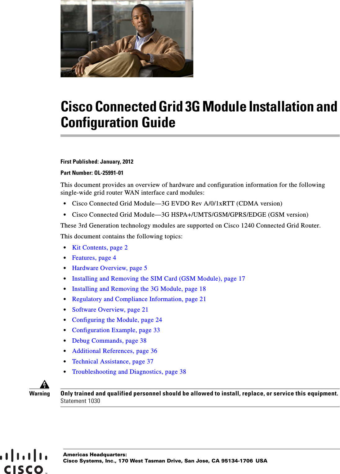
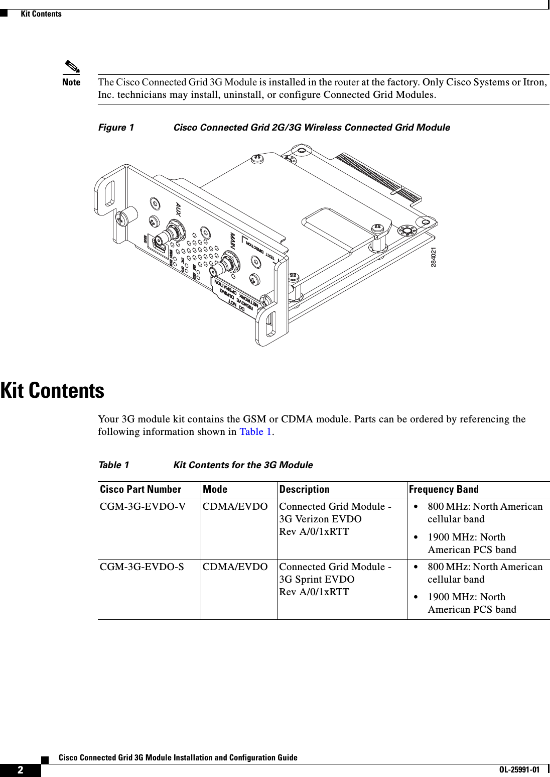
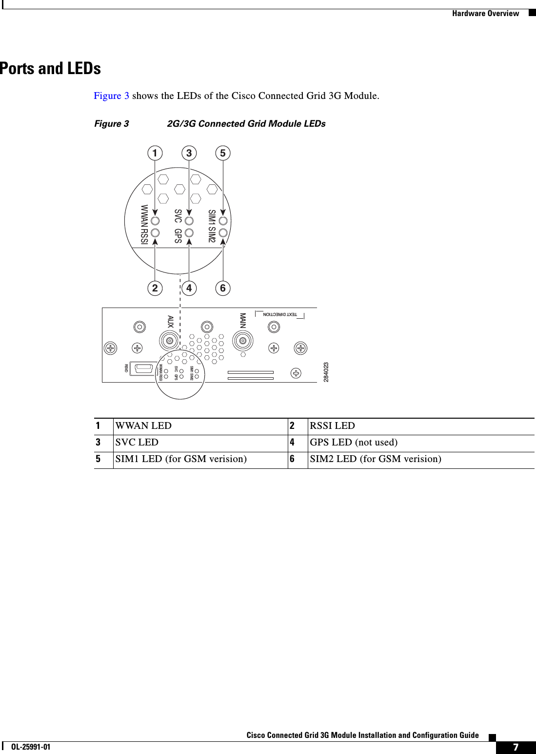
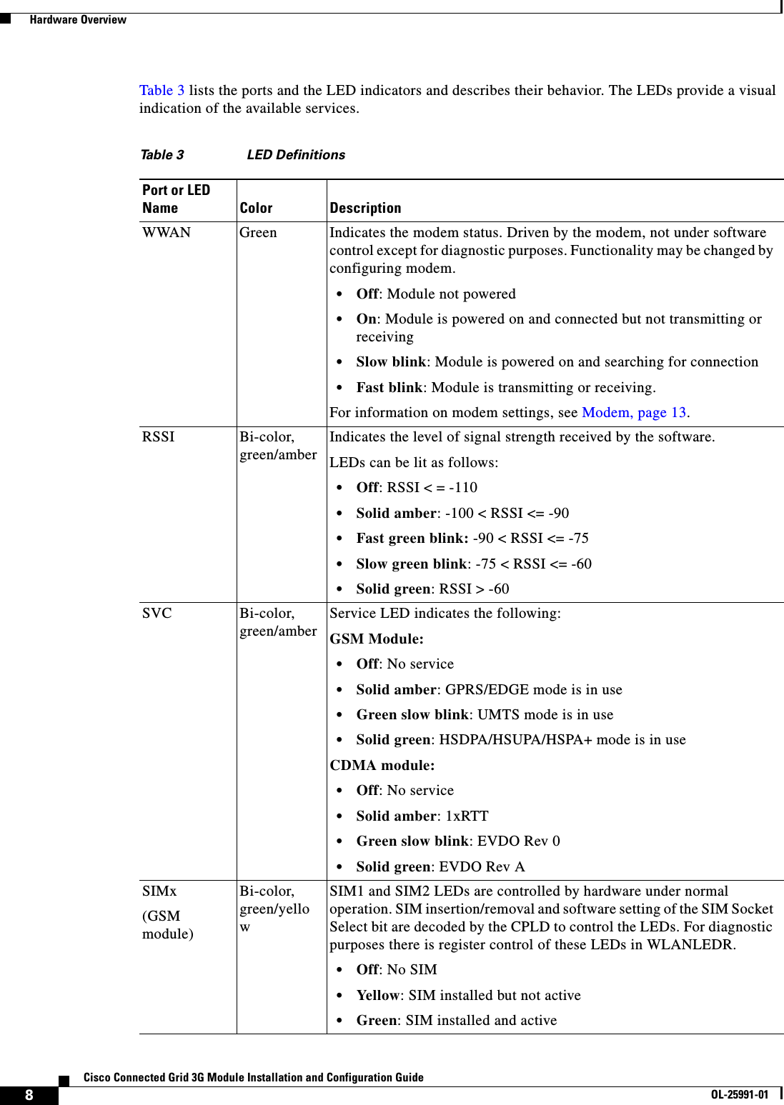
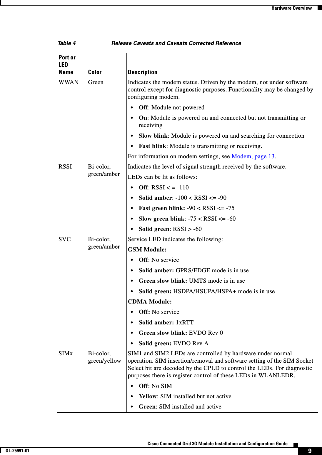
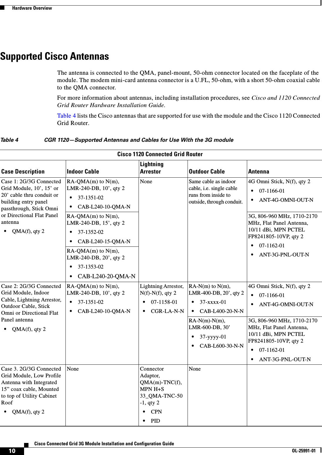
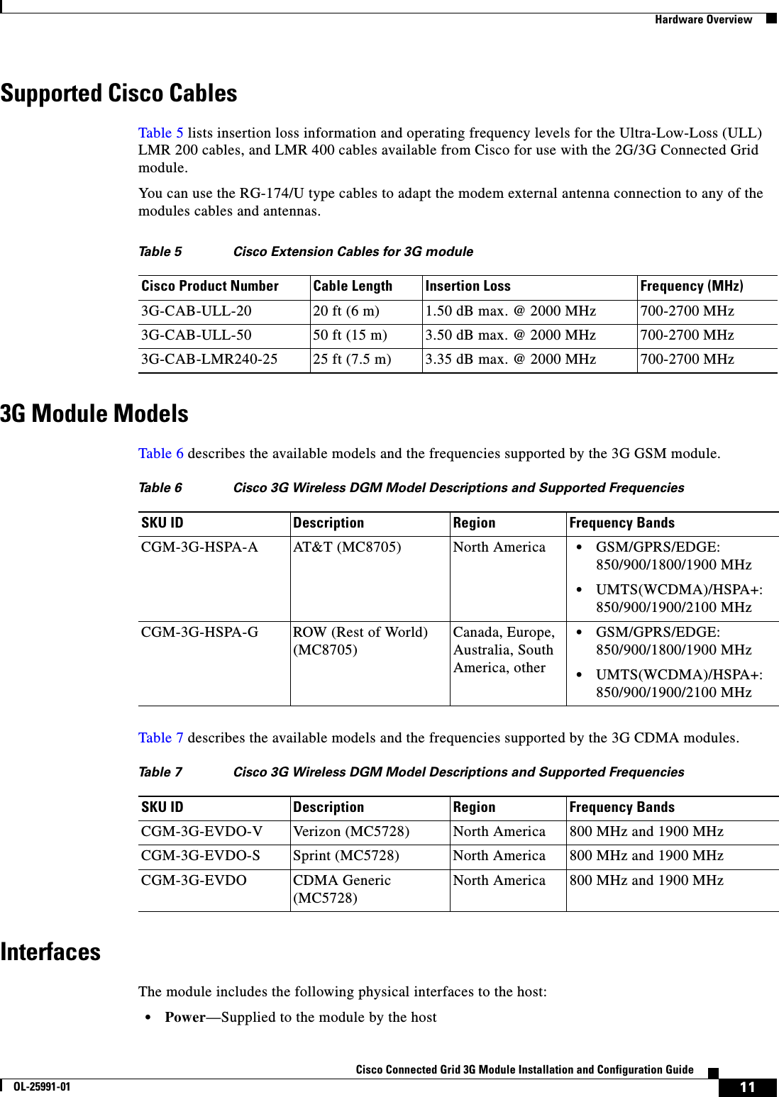
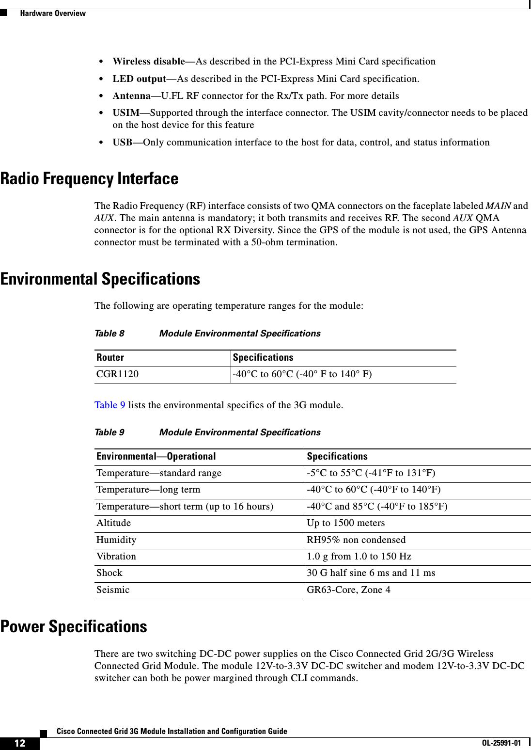
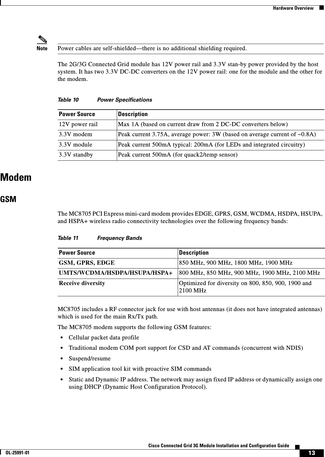
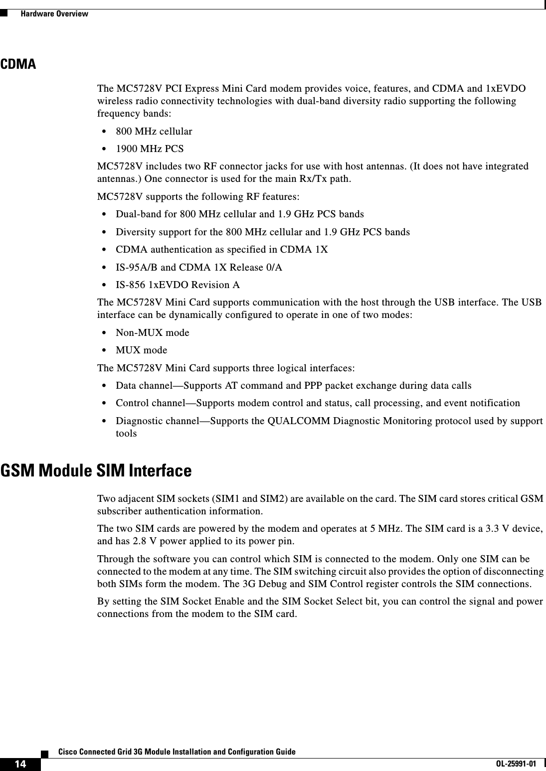
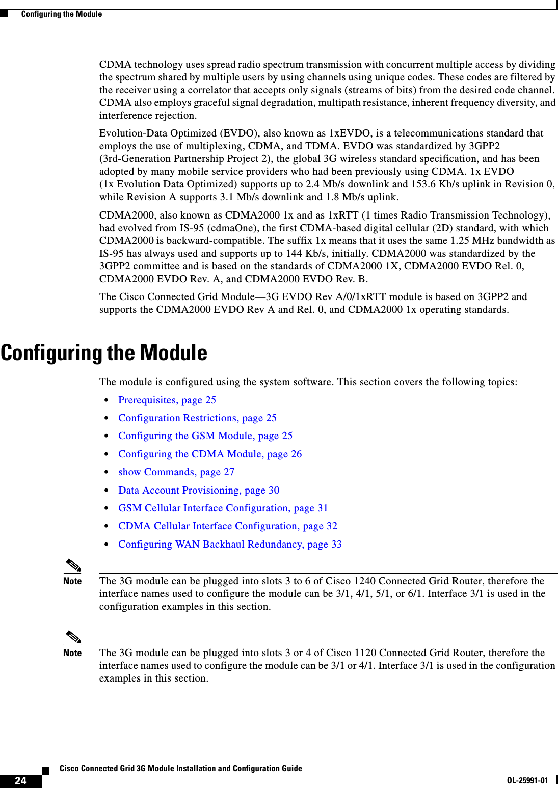
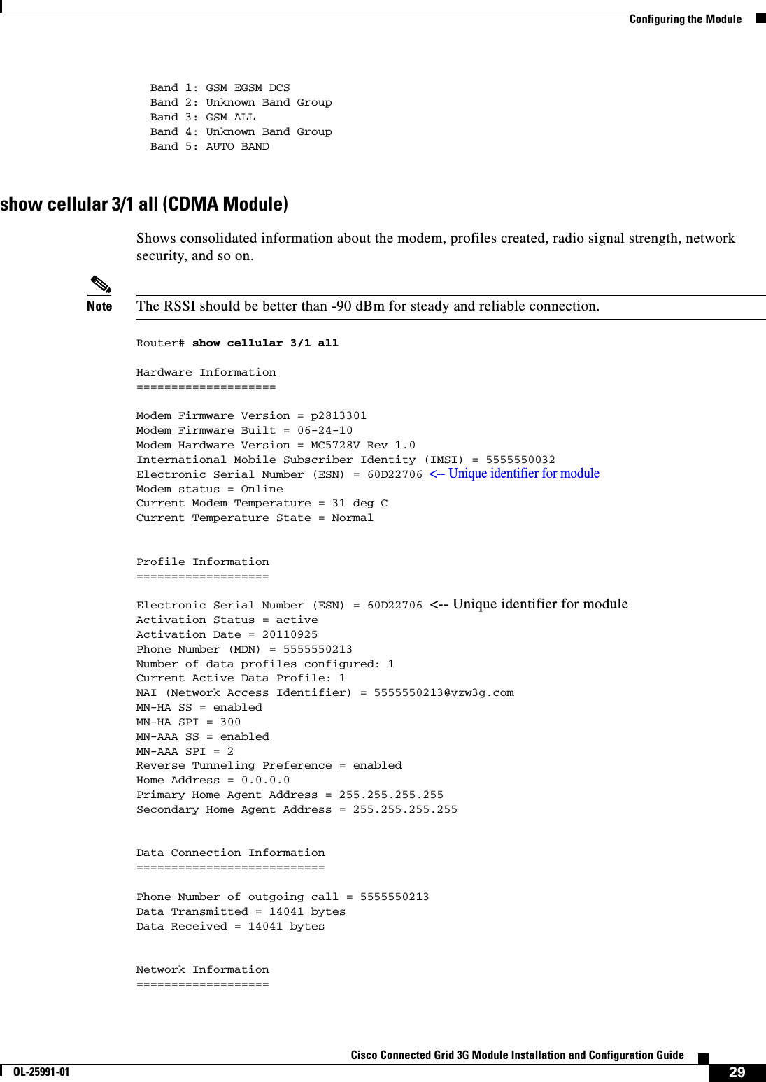
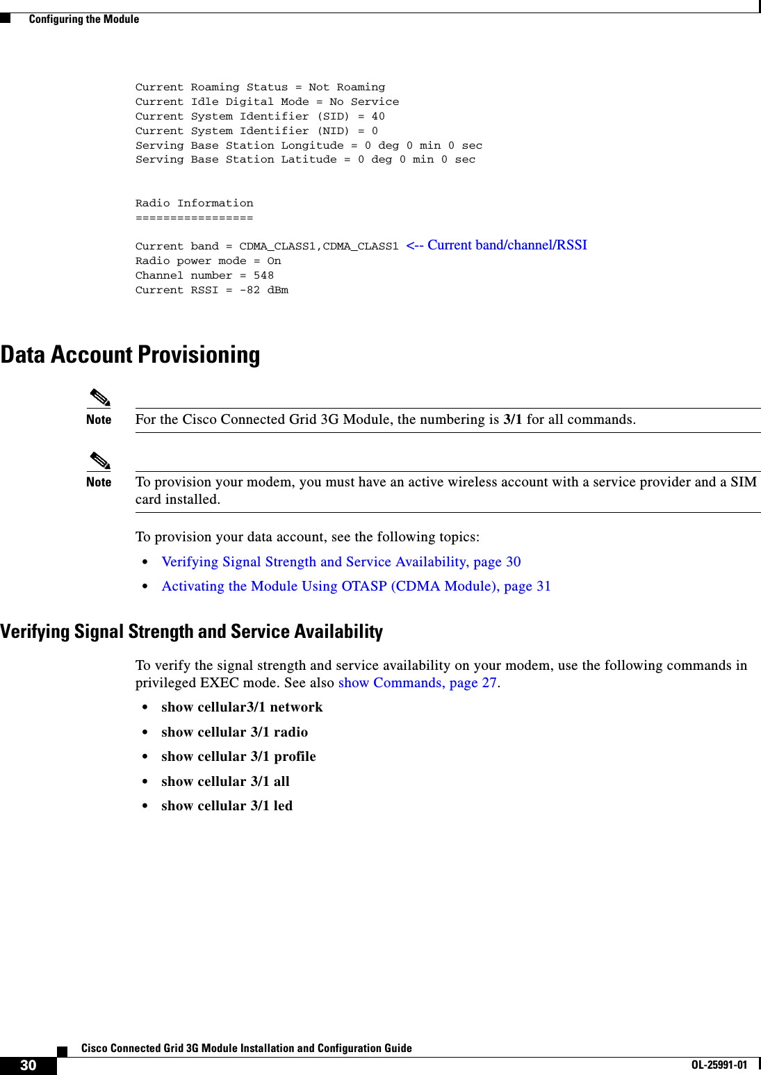
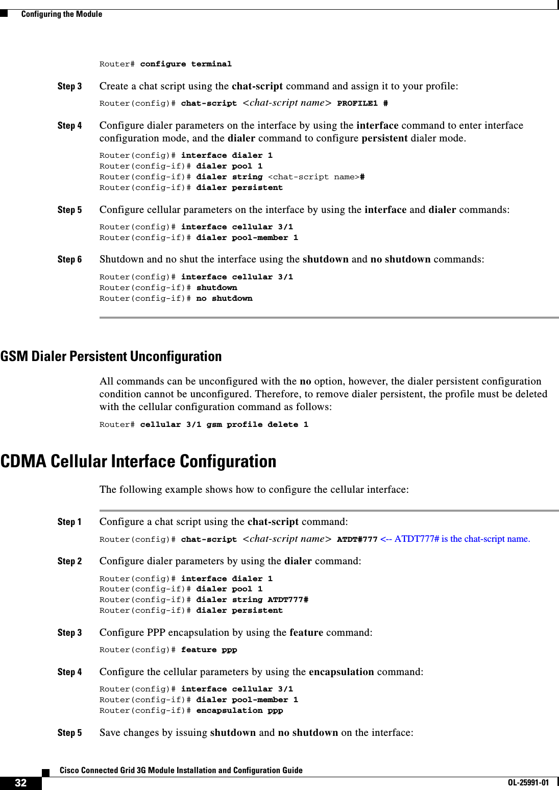
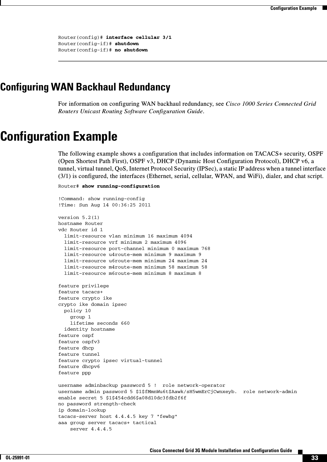
3G module manual
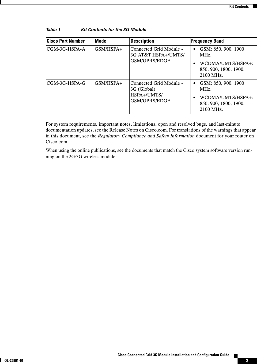
![16Cisco Connected Grid 3G Module Installation and Configuration GuideOL-25991-01 Hardware OverviewMemory SpecificationsThe memory specifications of the module are listed in Table 14.Module Power StatesThe module has the following power states: • Normal mode (default mode)—Module is active. Receive and Transmit modes are possible. In this state: –The module is fully powered –The module is capable of placing/receiving calls or establishing data connections on the wireless network –The USB interface is fully activeNote The module unit defaults to the Normal state when VCC is first applied. • Low power mode (airplane mode)—The module is active, but RF is disabled. In this state, RF (both Rx and Tx) is disabled on the module, but the USB interface is still active. This state is controlled though the host interface by the following software commands: –+CFUN=0 command (AT Command Set for User Equipment (UE) (Release 6)) –CDMA module: CNS_RADIO_POWER [0x1075] (CDMA CnS Reference (Document 2130754)) –GSM module: CNS_RADIO_POWER [0x1075] (MC87XX Modem CnS Reference (Document 2130602)) –Disable Modem command (MC87XX Modem CnS Reference (Document 2130602))Note The module goes from normal mode into low-power mode to suspend RF activity. This occurs when the module’s supply voltage exceeds either the high or low limits. The module returns to normal mode to resume RF activity. It occurs when the module’s supply voltage returns from critical to normal limits. • Disconnected mode—No power to the module. The host power source is disconnected from the module and all voltages associated with the module are at 0 V.CGR 1120 and CGR 1240 controls the power to the module, therefore the host can stay powered on and cut the power in order to put the module into the disconnected state.Table 14 Specifications to Connect to the SIM Sockets Memory Type Minimum MaximumDDR2 SDRAM 1Gb (128 Mb) NA (1Gb is sufficient for the Linux SDK design and modem firmware upgrade)DDR2 SDRAM for fixed platforms512 Mb (384 Mb for IOS and 128 Mb for the Linux)—](https://usermanual.wiki/Cisco-Systems/ALTMT0556.3G-module-manual/User-Guide-1630934-Page-16.png)
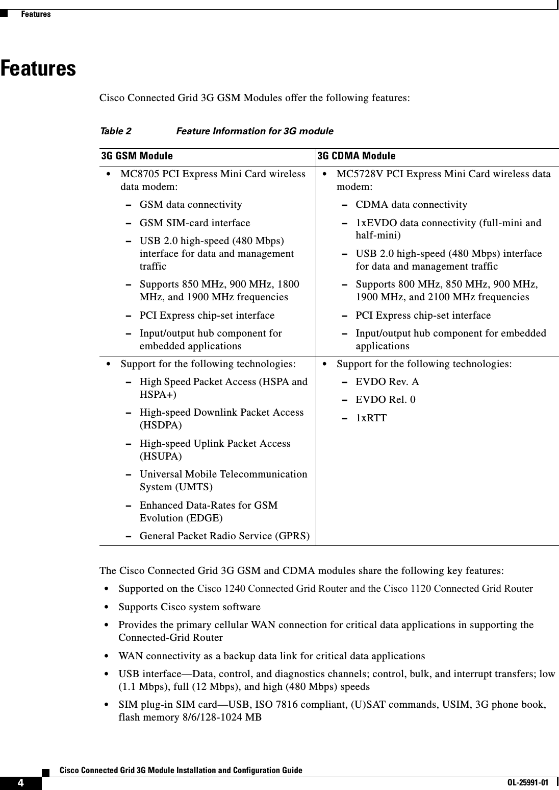
![25Cisco Connected Grid 3G Module Installation and Configuration GuideOL-25991-01 Configuring the ModulePrerequisitesTo configure the 3G module, you must meet the following requirements: • Have 2G/3G network coverage where your router will be physically located. For a complete list of supported carriers, see the product data sheet. • Subscribe to a service plan with a wireless service provider and obtain a SIM card. • Install the SIM card before configuring the 3G module. For instructions on how to install the SIM card, see the section, Installing the SIM Card (GSM Module), page 17.Configuration RestrictionsThe following restrictions apply to configuring the Cisco Connected Grid 3G Module: • Data connection can be originated only by the module. • Throughput: Due to the shared nature of wireless communications, the experienced throughput varies depending on the number of active users or congestion in a given network. • Cellular networks have higher latency compared to wired networks. Latency rates depend on the technology and carrier. Latency may be higher because of network congestion. • Any restrictions that are a part of the terms of service from your carrier.Configuring the GSM ModuleStep 1: Creating a GSM ProfileUse the cellular 3/1 gsm profile command to configure a GSM profile:Router# cellular 3/1 gsm profile create 1 <Access Point Name> [<authentication type <username> <password>] • Use <authentication type> if username and password is configured. • Use <username> if required by your carrier. • Use <password> if required by your carrier.See also GSM Cellular Interface Configuration, page 31.Step 2: Configuring a Chat ScriptUse the chat-script command to configure a GSM chat script:Router(config)# chat-script <chat-script name> PROFILE1](https://usermanual.wiki/Cisco-Systems/ALTMT0556.3G-module-manual/User-Guide-1630934-Page-25.png)
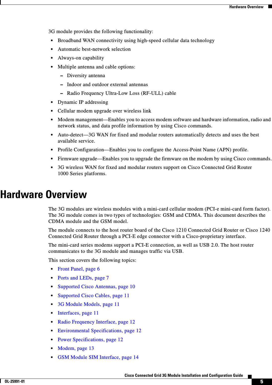
![31Cisco Connected Grid 3G Module Installation and Configuration GuideOL-25991-01 Configuring the ModuleDETAILED STEPSActivating the Module Using OTASP (CDMA Module)To activate the module using Over-The-Air Service Provisioning (OTASP), use the cellular 3/1 cdma activate otasp *22899 command.Note Do not hit a Enter (carriage return) until provisioning is complete—you will see “Over the air provisioning complete; Result = Success.” See below.Router# cellular 3/1 cdma activate otasp *22899Beginning OTASP activationOTASP number is *22899Router# <-- Do not hit Enter key-- provisioning is in process. OTA State = SPL unlock, Result = SuccessprovisingOTA State = Profile downloaded, Result = SuccessOTA State = MDN downloaded, Result = SuccessOTA State = Parameters committed to NVRAM, Result = SuccessOver the air provisioning complete; Result = Success <-- Activation successful. Hit Enter to return to promptRouter#To verify that the account has been provisioned and the modem has been activated, use the show cellular 3/1 profile command in EXEC mode:Router# show cellular 3/1 profile* - Default profileGSM Cellular Interface ConfigurationTo configure the cellular interface:Step 1 Create a profile on the interface 3/1 using the cellular command:Router# cellular 3/1 gsm profile create 1 <Access Point Name> [<username> <password>]Step 2 Configure terminal:Step Command PurposeStep 1 show cellular 3/1 network Displays information about the carrier network, cell site, and available service.Step 2 show cellular 3/1 radio Shows the radio signal strength.Note The RSSI should be better than -90 dBm for steady and reliable connection.Step 3 show cellular 3/1 profile Shows information about the modem data profiles created.Step 4 show cellular 3/1 security Shows the security information for the modem, such as SIM and modem lock status.Step 5 show cellular 3/1 all Shows consolidated information about the modem, profiles created, radio signal strength, network security, and so on.](https://usermanual.wiki/Cisco-Systems/ALTMT0556.3G-module-manual/User-Guide-1630934-Page-31.png)
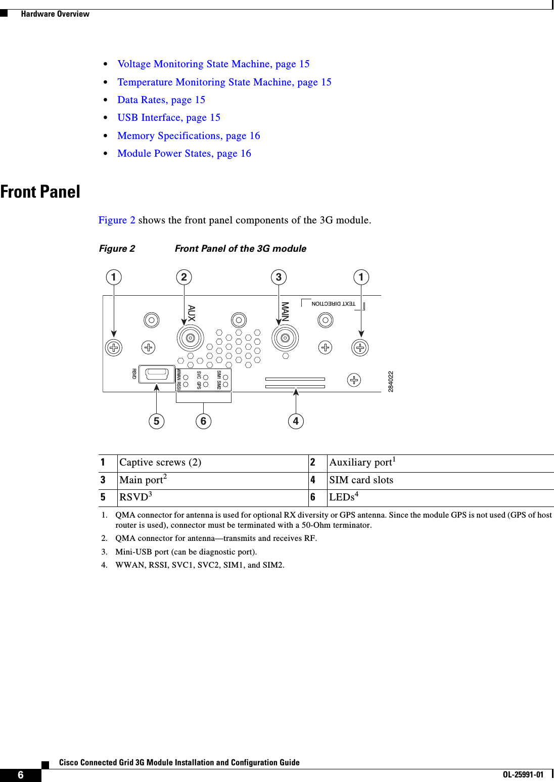
![38Cisco Connected Grid 3G Module Installation and Configuration GuideOL-25991-01 Troubleshooting and DiagnosticsTroubleshooting and DiagnosticsThis section provides the necessary background information and resources available for troubleshooting the 2G/3G Connected Grid module.For LED descriptions, see Ports and LEDs, page 7. • Debug Commands, page 38 • Modem AT Test Commands, page 38 • Checking Signal Strength, page 39 • Verifying Service Availability (GSM Module), page 39 • Successful Call Setup (GSM Module), page 41 • Retrieving the Electronic Serial Number, page 41 • Converting Hexadecimal ESN to Decimal Notation, page 42Debug CommandsThe following are sample output for the debug cellular commands:Router# debug cellular ? <0-10> Debug levelRouter# debug cellpm ? all All debugging error Error cellpm debug trace Trace cellpm debugRouter# debug chat ? error Error chat debug trace Trace chat debugRouter# debug dialer ? all All debugging error Error dialer debug trace Trace dialer debugModem AT Test CommandsThe following is the test cellular AT command. Note CDMA Module: Accessing the AT commands will end the connection.Router# test cellular 2/1 atcommandsatiDevice busy - issue +++ to abort connection before issuing AT commands+++NO CARRIERatiatiManufacturer: Sierra Wireless, Inc.Model: MC5728V Rev 1.0 (5)Revision: p2813301,10 [Jun 24 2010 12:18:30]](https://usermanual.wiki/Cisco-Systems/ALTMT0556.3G-module-manual/User-Guide-1630934-Page-38.png)