Cisco Systems ALTMT0556 Utility Meter Monitoring System User Manual 3G module manual
Cisco Systems Inc Utility Meter Monitoring System 3G module manual
Contents
- 1. user manual pt 1
- 2. 3G module manual
- 3. 900 MHz module manual
- 4. user manual pt 2
3G module manual

Americas Headquarters:
Cisco Systems, Inc., 170 West Tasman Drive, San Jose, CA 95134-1706 USA
Cisco Connected Grid 3G Module Installation and
Configuration Guide
First Published: January, 2012
Part Number: OL-25991-01
This document provides an overview of hardware and configuration information for the following
single-wide grid router WAN interface card modules:
• Cisco Connected Grid Module—3G EVDO Rev A/0/1xRTT (CDMA version)
• Cisco Connected Grid Module—3G HSPA+/UMTS/GSM/GPRS/EDGE (GSM version)
These 3rd Generation technology modules are supported on Cisco 1240 Connected Grid Router.
This document contains the following topics:
• Kit Contents, page 2
• Features, page 4
• Hardware Overview, page 5
• Installing and Removing the SIM Card (GSM Module), page 17
• Installing and Removing the 3G Module, page 18
• Regulatory and Compliance Information, page 21
• Software Overview, page 21
• Configuring the Module, page 24
• Configuration Example, page 33
• Debug Commands, page 38
• Additional References, page 36
• Technical Assistance, page 37
• Troubleshooting and Diagnostics, page 38
Warning
Only trained and qualified personnel should be allowed to install, replace, or service this equipment.
Statement 1030
2
Cisco Connected Grid 3G Module Installation and Configuration Guide
OL-25991-01
Kit Contents
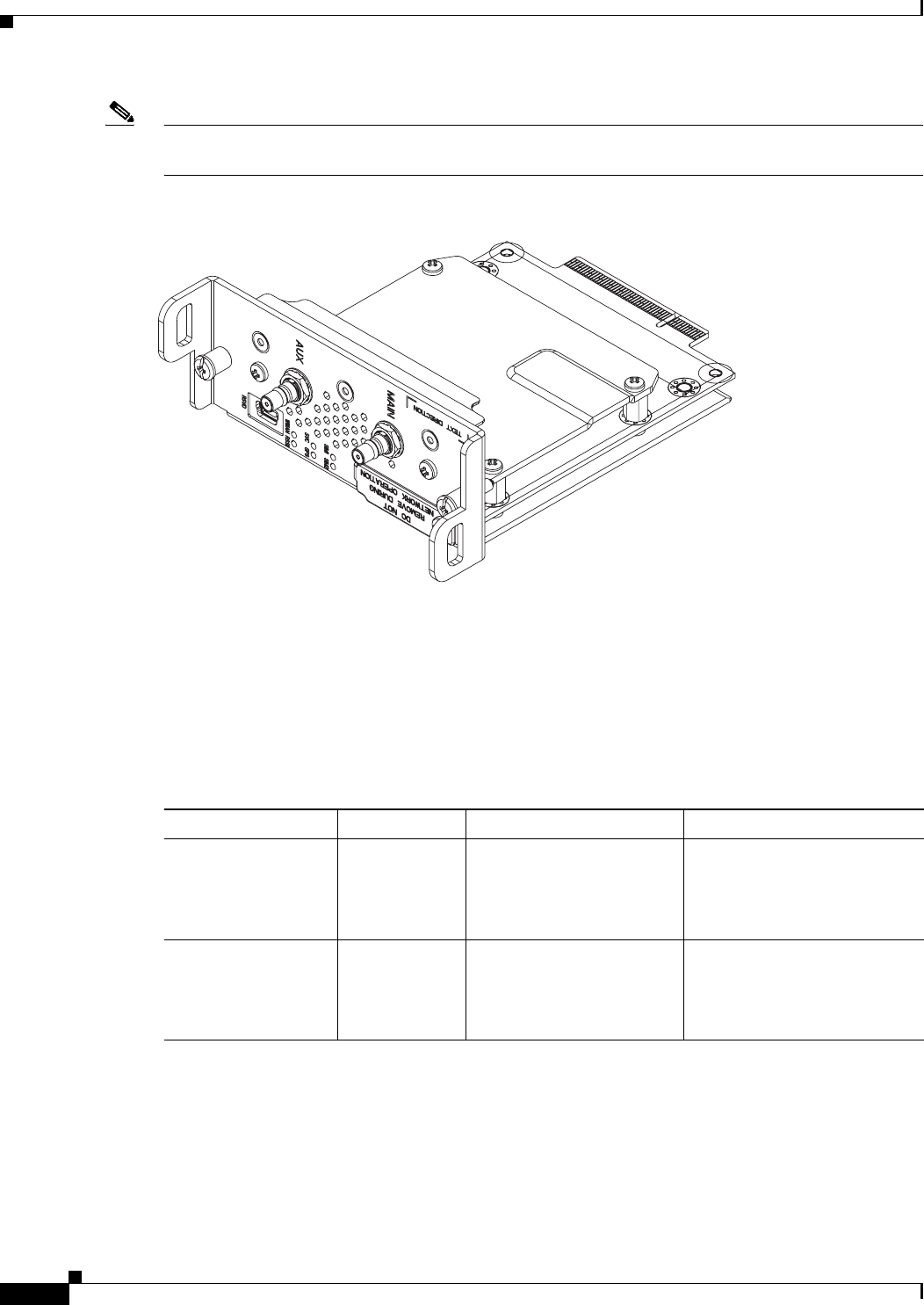
Note The Cisco Connected Grid 3G Module is installed in the router at the factory. Only Cisco Systems or Itron,
Inc. technicians may install, uninstall, or configure Connected Grid Modules.
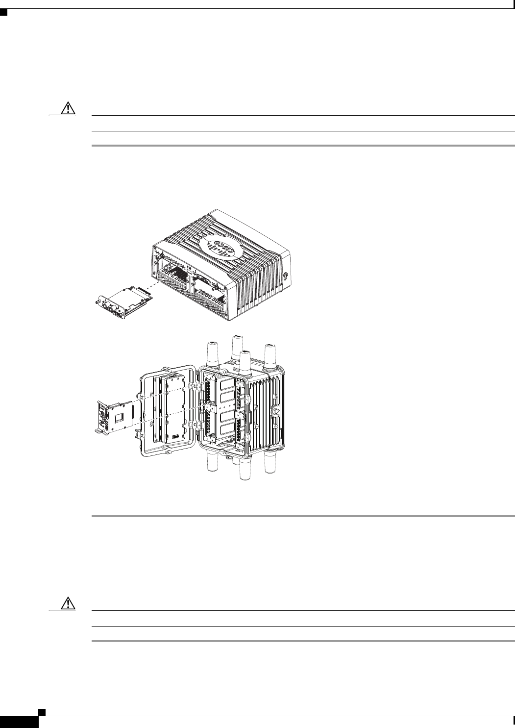
Figure 1 Cisco Connected Grid 2G/3G Wireless Connected Grid Module
Kit Contents
Your 3G module kit contains the GSM or CDMA module. Parts can be ordered by referencing the
following information shown in Table 1.
284021
Table 1 Kit Contents for the 3G Module
Cisco Part Number Mode Description Frequency Band
CGM-3G-EVDO-V CDMA/EVDO Connected Grid Module -
3G Verizon EVDO
Rev A/0/1xRTT
• 800 MHz: North American
cellular band
• 1900 MHz: North
American PCS band
CGM-3G-EVDO-S CDMA/EVDO Connected Grid Module -
3G Sprint EVDO
Rev A/0/1xRTT
• 800 MHz: North American
cellular band
• 1900 MHz: North
American PCS band

3
Cisco Connected Grid 3G Module Installation and Configuration Guide
OL-25991-01
Kit Contents
For system requirements, important notes, limitations, open and resolved bugs, and last-minute
documentation updates, see the Release Notes on Cisco.com. For translations of the warnings that appear
in this document, see the Regulatory Compliance and Safety Information document for your router on
Cisco.com.
When using the online publications, see the documents that match the Cisco system software version run-
ning on the 2G/3G wireless module.
CGM-3G-HSPA-A GSM/HSPA+ Connected Grid Module -
3G AT&T HSPA+/UMTS/
GSM/GPRS/EDGE
• GSM: 850, 900, 1900
MHz.
• WCDMA/UMTS/HSPA+:
850, 900, 1800, 1900,
2100 MHz.
CGM-3G-HSPA-G GSM/HSPA+ Connected Grid Module -
3G (Global)
HSPA+/UMTS/
GSM/GPRS/EDGE
• GSM: 850, 900, 1900
MHz.
• WCDMA/UMTS/HSPA+:
850, 900, 1800, 1900,
2100 MHz.
Table 1 Kit Contents for the 3G Module
Cisco Part Number Mode Description Frequency Band

4
Cisco Connected Grid 3G Module Installation and Configuration Guide
OL-25991-01
Features
Features
Cisco Connected Grid 3G GSM Modules offer the following features:
The Cisco Connected Grid 3G GSM and CDMA modules share the following key features:
• Supported on the Cisco 1240 Connected Grid Router and the Cisco 1120 Connected Grid Router
• Supports Cisco system software
• Provides the primary cellular WAN connection for critical data applications in supporting the
Connected-Grid Router
• WAN connectivity as a backup data link for critical data applications
• USB interface—Data, control, and diagnostics channels; control, bulk, and interrupt transfers; low
(1.1 Mbps), full (12 Mbps), and high (480 Mbps) speeds
• SIM plug-in SIM card—USB, ISO 7816 compliant, (U)SAT commands, USIM, 3G phone book,
flash memory 8/6/128-1024 MB
Table 2 Feature Information for 3G module
3G GSM Module 3G CDMA Module
• MC8705 PCI Express Mini Card wireless
data modem:
–
GSM data connectivity
–
GSM SIM-card interface
–
USB 2.0 high-speed (480 Mbps)
interface for data and management
traffic
–
Supports 850 MHz, 900 MHz, 1800
MHz, and 1900 MHz frequencies
–
PCI Express chip-set interface
–
Input/output hub component for
embedded applications
• MC5728V PCI Express Mini Card wireless data
modem:
–
CDMA data connectivity
–
1xEVDO data connectivity (full-mini and
half-mini)
–
USB 2.0 high-speed (480 Mbps) interface
for data and management traffic
–
Supports 800 MHz, 850 MHz, 900 MHz,
1900 MHz, and 2100 MHz frequencies
–
PCI Express chip-set interface
–
Input/output hub component for embedded
applications
• Support for the following technologies:
–
High Speed Packet Access (HSPA and
HSPA+)
–
High-speed Downlink Packet Access
(HSDPA)
–
High-speed Uplink Packet Access
(HSUPA)
–
Universal Mobile Telecommunication
System (UMTS)
–
Enhanced Data-Rates for GSM
Evolution (EDGE)
–
General Packet Radio Service (GPRS)
• Support for the following technologies:
–
EVDO Rev. A
–
EVDO Rel. 0
–
1xRTT

5
Cisco Connected Grid 3G Module Installation and Configuration Guide
OL-25991-01
Hardware Overview
3G module provides the following functionality:
• Broadband WAN connectivity using high-speed cellular data technology
• Automatic best-network selection
• Always-on capability
• Multiple antenna and cable options:
–
Diversity antenna
–
Indoor and outdoor external antennas
–
Radio Frequency Ultra-Low Loss (RF-ULL) cable
• Dynamic IP addressing
• Cellular modem upgrade over wireless link
• Modem management—Enables you to access modem software and hardware information, radio and
network status, and data profile information by using Cisco commands.
• Auto-detect—3G WAN for fixed and modular routers automatically detects and uses the best
available service.
• Profile Configuration—Enables you to configure the Access-Point Name (APN) profile.
• Firmware upgrade—Enables you to upgrade the firmware on the modem by using Cisco commands.
• 3G wireless WAN for fixed and modular routers support on Cisco Connected Grid Router
1000 Series platforms.
Hardware Overview
The 3G modules are wireless modules with a mini-card cellular modem (PCI-e mini-card form factor).
The 3G module comes in two types of technologies: GSM and CDMA. This document describes the
CDMA module and the GSM model.
The module connects to the host router board of the Cisco 1210 Connected Grid Router or Cisco 1240
Connected Grid Router through a PCI-E edge connector with a Cisco-proprietary interface.
The mini-card series modems support a PCI-E connection, as well as USB 2.0. The host router
communicates to the 3G module and manages traffic via USB.
This section covers the following topics:
• Front Panel, page 6
• Ports and LEDs, page 7
• Supported Cisco Antennas, page 10
• Supported Cisco Cables, page 11
• 3G Module Models, page 11
• Interfaces, page 11
• Radio Frequency Interface, page 12
• Environmental Specifications, page 12
• Power Specifications, page 12
• Modem, page 13
• GSM Module SIM Interface, page 14
6
Cisco Connected Grid 3G Module Installation and Configuration Guide
OL-25991-01
Hardware Overview
• Voltage Monitoring State Machine, page 15
• Temperature Monitoring State Machine, page 15
• Data Rates, page 15
• USB Interface, page 15
• Memory Specifications, page 16
• Module Power States, page 16
Front Panel
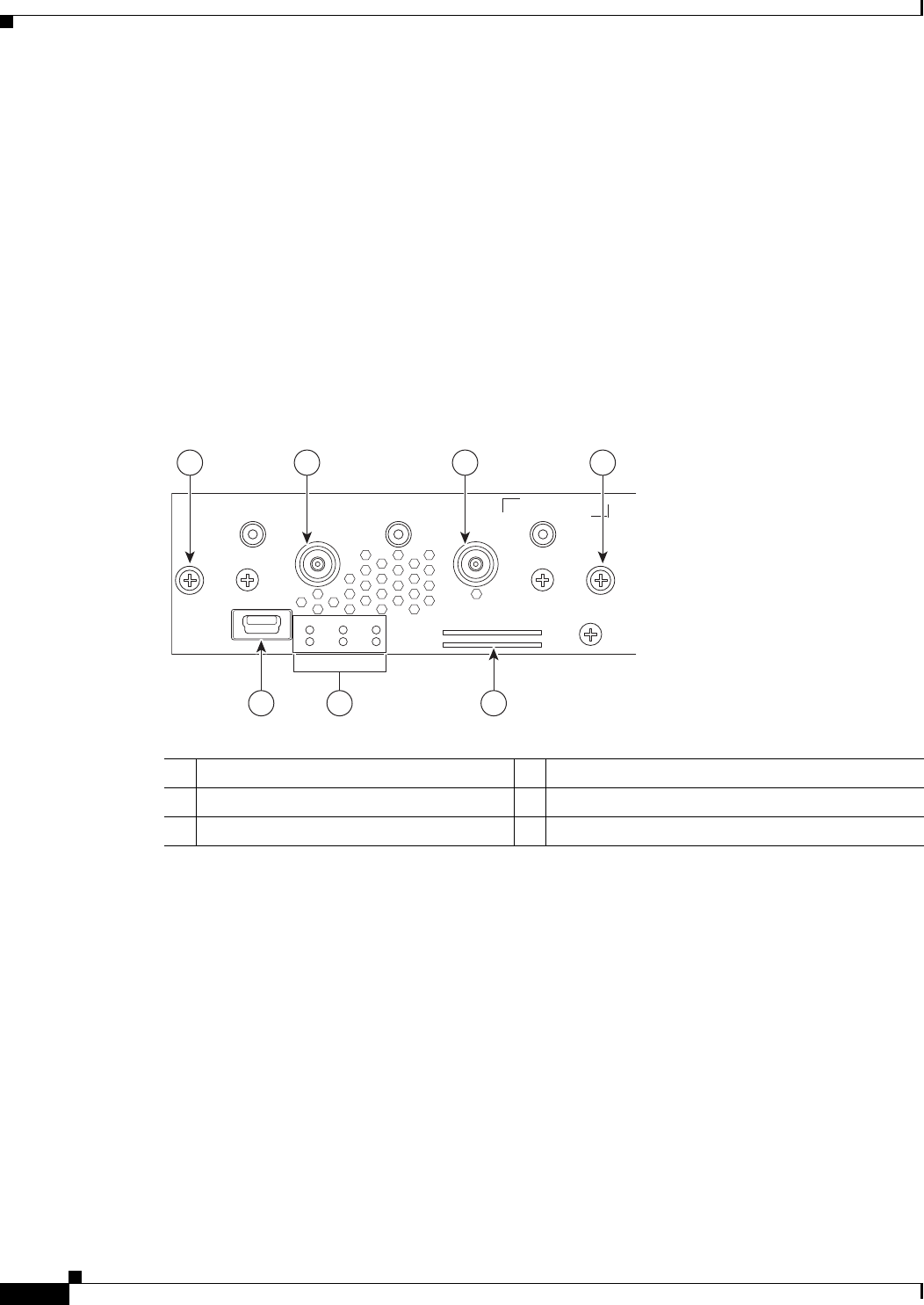
Figure 2 shows the front panel components of the 3G module.
Figure 2 Front Panel of the 3G module
1Captive screws (2) 2Auxiliary port1
1. QMA connector for antenna is used for optional RX diversity or GPS antenna. Since the module GPS is not used (GPS of host
router is used), connector must be terminated with a 50-Ohm terminator.
3Main port2
2. QMA connector for antenna—transmits and receives RF.
4SIM card slots
5RSVD3
3. Mini-USB port (can be diagnostic port).
6LEDs4
4. WWAN, RSSI, SVC1, SVC2, SIM1, and SIM2.
284022
AUX
MAIN
RSVD
WWAN RSSI
SVC GPS
SIM1 SIM2
TEXT DIRECTION
1 12 3
45 6
7
Cisco Connected Grid 3G Module Installation and Configuration Guide
OL-25991-01
Hardware Overview
Ports and LEDs
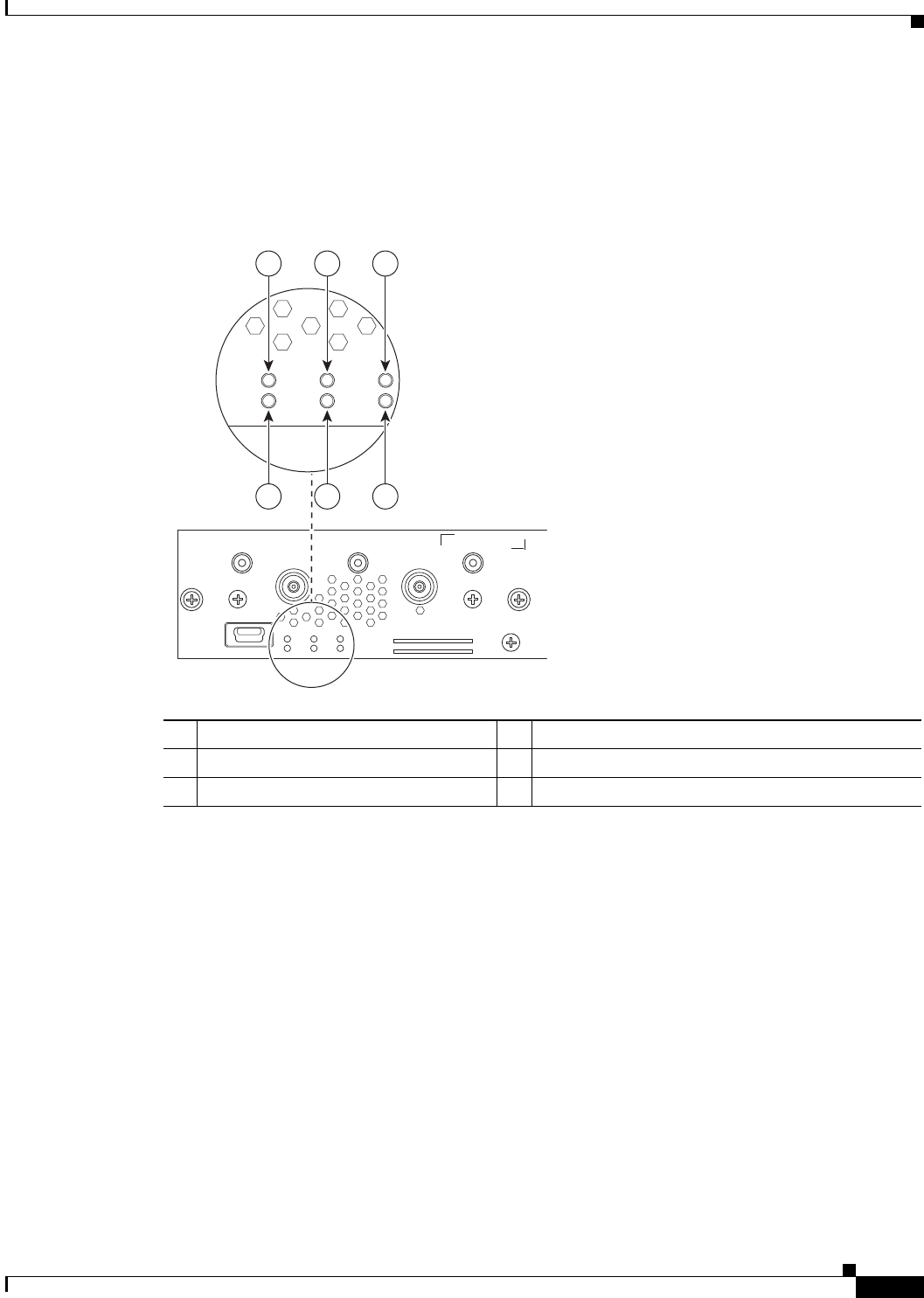
Figure 3 shows the LEDs of the Cisco Connected Grid 3G Module.
Figure 3 2G/3G Connected Grid Module LEDs
1WWAN LED 2RSSI LED
3SVC LED 4GPS LED (not used)
5SIM1 LED (for GSM verision) 6SIM2 LED (for GSM verision)
284023
AUX
MAIN
RSVD
WWAN RSSI
SVC GPS
SIM1 SIM2
TEXT DIRECTION
WWAN RSSI
SVC GPS
SIM1 SIM2
1 3 5
2 4 6

8
Cisco Connected Grid 3G Module Installation and Configuration Guide
OL-25991-01
Hardware Overview
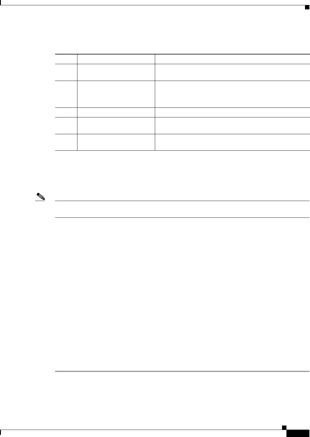
Table 3 lists the ports and the LED indicators and describes their behavior. The LEDs provide a visual
indication of the available services.
Table 3 LED Definitions
Port or LED
Name Color Description
WWAN Green Indicates the modem status. Driven by the modem, not under software
control except for diagnostic purposes. Functionality may be changed by
configuring modem.
• Off: Module not powered
• On: Module is powered on and connected but not transmitting or
receiving
• Slow blink: Module is powered on and searching for connection
• Fast blink: Module is transmitting or receiving.
For information on modem settings, see Modem, page 13.
RSSI Bi-color,
green/amber
Indicates the level of signal strength received by the software.
LEDs can be lit as follows:
• Off: RSSI < = -110
• Solid amber: -100 < RSSI <= -90
• Fast green blink: -90 < RSSI <= -75
• Slow green blink: -75 < RSSI <= -60
• Solid green: RSSI > -60
SVC Bi-color,
green/amber
Service LED indicates the following:
GSM Module:
• Off: No service
• Solid amber: GPRS/EDGE mode is in use
• Green slow blink: UMTS mode is in use
• Solid green: HSDPA/HSUPA/HSPA+ mode is in use
CDMA module:
• Off: No service
• Solid amber: 1xRTT
• Green slow blink: EVDO Rev 0
• Solid green: EVDO Rev A
SIMx
(GSM
module)
Bi-color,
green/yello
w
SIM1 and SIM2 LEDs are controlled by hardware under normal
operation. SIM insertion/removal and software setting of the SIM Socket
Select bit are decoded by the CPLD to control the LEDs. For diagnostic
purposes there is register control of these LEDs in WLANLEDR.
• Off: No SIM
• Ye l l o w : SIM installed but not active
• Green: SIM installed and active

9
Cisco Connected Grid 3G Module Installation and Configuration Guide
OL-25991-01
Hardware Overview
Table 4 Release Caveats and Caveats Corrected Reference
Port or
LED
Name Color Description
WWAN Green Indicates the modem status. Driven by the modem, not under software
control except for diagnostic purposes. Functionality may be changed by
configuring modem.
• Off: Module not powered
• On: Module is powered on and connected but not transmitting or
receiving
• Slow blink: Module is powered on and searching for connection
• Fast blink: Module is transmitting or receiving.
For information on modem settings, see Modem, page 13.
RSSI Bi-color,
green/amber
Indicates the level of signal strength received by the software.
LEDs can be lit as follows:
• Off: RSSI < = -110
• Solid amber: -100 < RSSI <= -90
• Fast green blink: -90 < RSSI <= -75
• Slow green blink: -75 < RSSI <= -60
• Solid green: RSSI > -60
SVC Bi-color,
green/amber
Service LED indicates the following:
GSM Module:
• Off: No service
• Solid amber: GPRS/EDGE mode is in use
• Green slow blink: UMTS mode is in use
• Solid green: HSDPA/HSUPA/HSPA+ mode is in use
CDMA Module:
• Off: No service
• Solid amber: 1xRTT
• Green slow blink: EVDO Rev 0
• Solid green: EVDO Rev A
SIMx Bi-color,
green/yellow
SIM1 and SIM2 LEDs are controlled by hardware under normal
operation. SIM insertion/removal and software setting of the SIM Socket
Select bit are decoded by the CPLD to control the LEDs. For diagnostic
purposes there is register control of these LEDs in WLANLEDR.
• Off: No SIM
• Yellow: SIM installed but not active
• Green: SIM installed and active

10
Cisco Connected Grid 3G Module Installation and Configuration Guide
OL-25991-01
Hardware Overview
Supported Cisco Antennas
The antenna is connected to the QMA, panel-mount, 50-ohm connector located on the faceplate of the
module. The modem mini-card antenna connector is a U.FL, 50-ohm, with a short 50-ohm coaxial cable
to the QMA connector.
For more information about antennas, including installation procedures, see Cisco and 1120 Connected
Grid Router Hardware Installation Guide.
Table 4 lists the Cisco antennas that are supported for use with the module and the Cisco 1120 Connected
Grid Router.
Table 4 CGR 1120—Supported Antennas and Cables for Use With the 3G module
Cisco 1120 Connected Grid Router
Case Description Indoor Cable
Lightning
Arrestor Outdoor Cable Antenna
Case 1: 2G/3G Connected
Grid Module, 10’, 15’ or
20’ cable thru conduit or
building entry panel
passthrough, Stick Omni
or Directional Flat Panel
antenna
• QMA(f), qty 2
RA-QMA(m) to N(m),
LMR-240-DB, 10’, qty 2
• 37-1351-02
• CAB-L240-10-QMA-N
None Same cable as indoor
cable, i.e. single cable
runs from inside to
outside, through conduit.
4G Omni Stick, N(f), qty 2
• 07-1166-01
• ANT-4G-OMNI-OUT-N
RA-QMA(m) to N(m),
LMR-240-DB, 15’, qty 2
• 37-1352-02
• CAB-L240-15-QMA-N
3G, 806-960 MHz, 1710-2170
MHz, Flat Panel Antenna,
10/11 dBi, MPN PCTEL
FP8241805-10VP, qty 2
• 07-1162-01
• ANT-3G-PNL-OUT-N
RA-QMA(m) to N(m),
LMR-240-DB, 20’, qty 2
• 37-1353-02
• CAB-L240-20-QMA-N
Case 2: 2G/3G Connected
Grid Module, Indoor
Cable, Lightning Arrestor,
Outdoor Cable, Stick
Omni or Directional Flat
Panel antenna
• QMA(f), qty 2
RA-QMA(m) to N(m),
LMR-240-DB, 10’, qty 2
• 37-1351-02
• CAB-L240-10-QMA-N
Lightning Arrestor,
N(f)-N(f), qty 2
• 07-1158-01
• CGR-LA-N-N
RA-N(m) to N(m),
LMR-400-DB, 20’, qty 2
• 37-xxxx-01
• CAB-L400-20-N-N
4G Omni Stick, N(f), qty 2
• 07-1166-01
• ANT-4G-OMNI-OUT-N
RA-N(m)-N(m),
LMR-600-DB, 30’
• 37-yyyy-01
• CAB-L600-30-N-N
3G, 806-960 MHz, 1710-2170
MHz, Flat Panel Antenna,
10/11 dBi, MPN PCTEL
FP8241805-10VP, qty 2
• 07-1162-01
• ANT-3G-PNL-OUT-N
Case 3. 2G/3G Connected
Grid Module, Low Profile
Antenna with Integrated
15” coax cable, Mounted
to top of Utility Cabinet
Roof
• QMA(f), qty 2
None Connector
Adaptor,
QMA(m)-TNC(f),
MPN H+S
33_QMA-TNC-50
-1, qty 2
• CPN
• PID
None
11
Cisco Connected Grid 3G Module Installation and Configuration Guide
OL-25991-01
Hardware Overview
Supported Cisco Cables
Table 5 lists insertion loss information and operating frequency levels for the Ultra-Low-Loss (ULL)
LMR 200 cables, and LMR 400 cables available from Cisco for use with the 2G/3G Connected Grid
module.
You can use the RG-174/U type cables to adapt the modem external antenna connection to any of the
modules cables and antennas.
3G Module Models
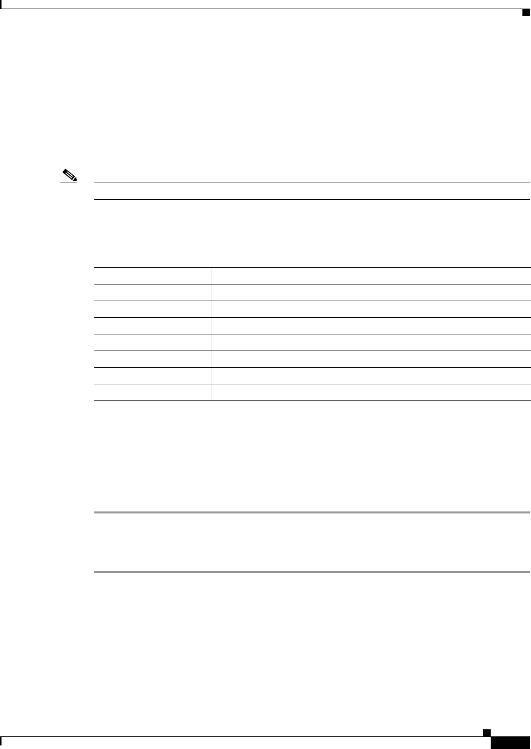
Table 6 describes the available models and the frequencies supported by the 3G GSM module.
Table 7 describes the available models and the frequencies supported by the 3G CDMA modules.
Interfaces
The module includes the following physical interfaces to the host:
• Power—Supplied to the module by the host
Table 5 Cisco Extension Cables for 3G module
Cisco Product Number Cable Length Insertion Loss Frequency (MHz)
3G-CAB-ULL-20 20 ft (6 m) 1.50 dB max. @ 2000 MHz 700-2700 MHz
3G-CAB-ULL-50 50 ft (15 m) 3.50 dB max. @ 2000 MHz 700-2700 MHz
3G-CAB-LMR240-25 25 ft (7.5 m) 3.35 dB max. @ 2000 MHz 700-2700 MHz
Table 6 Cisco 3G Wireless DGM Model Descriptions and Supported Frequencies
SKU ID Description Region Frequency Bands
CGM-3G-HSPA-A AT&T (MC8705) North America • GSM/GPRS/EDGE:
850/900/1800/1900 MHz
• UMTS(WCDMA)/HSPA+:
850/900/1900/2100 MHz
CGM-3G-HSPA-G ROW (Rest of World)
(MC8705)
Canada, Europe,
Australia, South
America, other
• GSM/GPRS/EDGE:
850/900/1800/1900 MHz
• UMTS(WCDMA)/HSPA+:
850/900/1900/2100 MHz
Table 7 Cisco 3G Wireless DGM Model Descriptions and Supported Frequencies
SKU ID Description Region Frequency Bands
CGM-3G-EVDO-V Verizon (MC5728) North America 800 MHz and 1900 MHz
CGM-3G-EVDO-S Sprint (MC5728) North America 800 MHz and 1900 MHz
CGM-3G-EVDO CDMA Generic
(MC5728)
North America 800 MHz and 1900 MHz
12
Cisco Connected Grid 3G Module Installation and Configuration Guide
OL-25991-01
Hardware Overview
• Wireless disable—As described in the PCI-Express Mini Card specification
• LED output—As described in the PCI-Express Mini Card specification.
• Antenna—U.FL RF connector for the Rx/Tx path. For more details
• USIM—Supported through the interface connector. The USIM cavity/connector needs to be placed
on the host device for this feature
• USB—Only communication interface to the host for data, control, and status information
Radio Frequency Interface
The Radio Frequency (RF) interface consists of two QMA connectors on the faceplate labeled MAIN and
AUX. The main antenna is mandatory; it both transmits and receives RF. The second AUX QMA
connector is for the optional RX Diversity. Since the GPS of the module is not used, the GPS Antenna
connector must be terminated with a 50-ohm termination.
Environmental Specifications
The following are operating temperature ranges for the module:
Table 9 lists the environmental specifics of the 3G module.
Power Specifications
There are two switching DC-DC power supplies on the Cisco Connected Grid 2G/3G Wireless
Connected Grid Module. The module 12V-to-3.3V DC-DC switcher and modem 12V-to-3.3V DC-DC
switcher can both be power margined through CLI commands.
Table 8 Module Environmental Specifications
Router Specifications
CGR1120 -40°C to 60°C (-40° F to 140° F)
Table 9 Module Environmental Specifications
Environmental—Operational Specifications
Temperature—standard range -5°C to 55°C (-41°F to 131°F)
Temperature—long term -40°C to 60°C (-40°F to 140°F)
Temperature—short term (up to 16 hours) -40°C and 85°C (-40°F to 185°F)
Altitude Up to 1500 meters
Humidity RH95% non condensed
Vibration 1.0 g from 1.0 to 150 Hz
Shock 30 G half sine 6 ms and 11 ms
Seismic GR63-Core, Zone 4

13
Cisco Connected Grid 3G Module Installation and Configuration Guide
OL-25991-01
Hardware Overview
Note Power cables are self-shielded—there is no additional shielding required.
The 2G/3G Connected Grid module has 12V power rail and 3.3V stan-by power provided by the host
system. It has two 3.3V DC-DC converters on the 12V power rail: one for the module and the other for
the modem.
Modem
GSM
The MC8705 PCI Express mini-card modem provides EDGE, GPRS, GSM, WCDMA, HSDPA, HSUPA,
and HSPA+ wireless radio connectivity technologies over the following frequency bands:
MC8705 includes a RF connector jack for use with host antennas (it does not have integrated antennas)
which is used for the main Rx/Tx path.
The MC8705 modem supports the following GSM features:
• Cellular packet data profile
• Traditional modem COM port support for CSD and AT commands (concurrent with NDIS)
• Suspend/resume
• SIM application tool kit with proactive SIM commands
• Static and Dynamic IP address. The network may assign fixed IP address or dynamically assign one
using DHCP (Dynamic Host Configuration Protocol).
Table 10 Power Specifications
Power Source Description
12V power rail Max 1A (based on current draw from 2 DC-DC converters below)
3.3V modem Peak current 3.75A, average power: 3W (based on average current of ~0.8A)
3.3V module Peak current 500mA typical: 200mA (for LEDs and integrated circuitry)
3.3V standby Peak current 500mA (for quack2/temp sensor)
Table 11 Frequency Bands
Power Source Description
GSM, GPRS, EDGE 850 MHz, 900 MHz, 1800 MHz, 1900 MHz
UMTS/WCDMA/HSDPA/HSUPA/HSPA+ 800 MHz, 850 MHz, 900 MHz, 1900 MHz, 2100 MHz
Receive diversity Optimized for diversity on 800, 850, 900, 1900 and
2100 MHz

14
Cisco Connected Grid 3G Module Installation and Configuration Guide
OL-25991-01
Hardware Overview
CDMA
The MC5728V PCI Express Mini Card modem provides voice, features, and CDMA and 1xEVDO
wireless radio connectivity technologies with dual-band diversity radio supporting the following
frequency bands:
• 800 MHz cellular
• 1900 MHz PCS
MC5728V includes two RF connector jacks for use with host antennas. (It does not have integrated
antennas.) One connector is used for the main Rx/Tx path.
MC5728V supports the following RF features:
• Dual-band for 800 MHz cellular and 1.9 GHz PCS bands
• Diversity support for the 800 MHz cellular and 1.9 GHz PCS bands
• CDMA authentication as specified in CDMA 1X
• IS-95A/B and CDMA 1X Release 0/A
• IS-856 1xEVDO Revision A
The MC5728V Mini Card supports communication with the host through the USB interface. The USB
interface can be dynamically configured to operate in one of two modes:
• Non-MUX mode
• MUX mode
The MC5728V Mini Card supports three logical interfaces:
• Data channel—Supports AT command and PPP packet exchange during data calls
• Control channel—Supports modem control and status, call processing, and event notification
• Diagnostic channel—Supports the QUALCOMM Diagnostic Monitoring protocol used by support
tools
GSM Module SIM Interface
Two adjacent SIM sockets (SIM1 and SIM2) are available on the card. The SIM card stores critical GSM
subscriber authentication information.
The two SIM cards are powered by the modem and operates at 5 MHz. The SIM card is a 3.3 V device,
and has 2.8 V power applied to its power pin.
Through the software you can control which SIM is connected to the modem. Only one SIM can be
connected to the modem at any time. The SIM switching circuit also provides the option of disconnecting
both SIMs form the modem. The 3G Debug and SIM Control register controls the SIM connections.
By setting the SIM Socket Enable and the SIM Socket Select bit, you can control the signal and power
connections from the modem to the SIM card.

15
Cisco Connected Grid 3G Module Installation and Configuration Guide
OL-25991-01
Hardware Overview
Table 12 shows the options used to connect to SIM0 and SIM1 cards:
For information on installing and removing the SIM card, see Installing and Removing the SIM Card
(GSM Module), page 17.
Voltage Monitoring State Machine
A state machine in the 3G module monitors the VCC supply and the voltage conditions that trigger state
changes.
Temperature Monitoring State Machine
The state machine in the Cisco Connected Grid 2G/3G Wireless Connected Grid Module monitors the
embedded module temperature.
Data Rates
The actual throughput rates depend on many different factors, but the theoretical rates for the
technologies follows:
USB Interface
A USB interface is the only communication path used by the router and the module at full-speed (12
Mbps) and high-speed (480 Mbps) data rates. The host acts as the USB host device to interface with the
module. The module uses the USB standard to control the sleep and wake-up states.
Table 12 Specifications to Connect to the SIM Sockets
SIM Socket Enable SIM Socket Select State
0 — No SIM connected
1 0 SIM0 connected
1 1 SIM1 connected
Table 13 GSM and CDMA Data Rates
GSM CDMA
HSPA+: 21.1 Mbps Down; 5.76 Mbps Up EVDO Rev A: 3.1 Mbps Down; 1.8 Mbps Up
16
Cisco Connected Grid 3G Module Installation and Configuration Guide
OL-25991-01
Hardware Overview
Memory Specifications
The memory specifications of the module are listed in Table 14.
Module Power States
The module has the following power states:
• Normal mode (default mode)—Module is active. Receive and Transmit modes are possible. In this
state:
–
The module is fully powered
–
The module is capable of placing/receiving calls or establishing data connections on the
wireless network
–
The USB interface is fully active
Note The module unit defaults to the Normal state when VCC is first applied.
• Low power mode (airplane mode)—The module is active, but RF is disabled. In this state, RF (both
Rx and Tx) is disabled on the module, but the USB interface is still active. This state is controlled
though the host interface by the following software commands:
–
+CFUN=0 command (AT Command Set for User Equipment (UE) (Release 6))
–
CDMA module: CNS_RADIO_POWER [0x1075] (CDMA CnS Reference (Document
2130754))
–
GSM module: CNS_RADIO_POWER [0x1075] (MC87XX Modem CnS Reference
(Document 2130602))
–
Disable Modem command (MC87XX Modem CnS Reference (Document 2130602))
Note The module goes from normal mode into low-power mode to suspend RF activity. This
occurs when the module’s supply voltage exceeds either the high or low limits. The module
returns to normal mode to resume RF activity. It occurs when the module’s supply voltage
returns from critical to normal limits.
• Disconnected mode—No power to the module. The host power source is disconnected from the
module and all voltages associated with the module are at 0 V.
CGR 1120 and CGR 1240 controls the power to the module, therefore the host can stay powered on
and cut the power in order to put the module into the disconnected state.
Table 14 Specifications to Connect to the SIM Sockets
Memory Type Minimum Maximum
DDR2 SDRAM 1Gb (128 Mb) NA (1Gb is sufficient for the Linux SDK design and
modem firmware upgrade)
DDR2 SDRAM for
fixed platforms
512 Mb (384 Mb for
IOS and 128 Mb for
the Linux)
—

17
Cisco Connected Grid 3G Module Installation and Configuration Guide
OL-25991-01
Installing and Removing the SIM Card (GSM Module)
The module begins a shutdown sequence and powers off if it has been in a powered-on state for more
than 10.5 seconds and the host device drives the W_Disable# signal low for:
• MC8775/MC8775V: >= 50 ms
• Other devices: >= 500 ms
Installing and Removing the SIM Card (GSM Module)
Two GSM (Global System for Mobile Communications) SIM card sockets for storing critical subscriber
authentication information. The SIM card can be installed in either of the two available sockets
accessible on the front panel of the Cisco Connected Grid 3G Module.
Note You must reload the system after installing or changing the SIM card.
Preventing Electrostatic Discharge Damage
Electrostatic Discharge (ESD) damage can occur when electronic cards or components are handled
improperly, and can result in complete or intermittent failures.
To prevent ESD damage:
• Always use an ESD wrist or ankle strap and ensure that it makes good skin contact
• Connect the equipment end of the strap to an unfinished chassis surface
• Place a removed compact SIM card on an antistatic surface or in a static shielding bag. If the card
will be returned to the factory, immediately place it in a static shielding bag
• Avoid contact between the card and clothing. The wrist strap protects the card from ESD voltages
on the body only; ESD voltages on clothing can still cause damage
• Do not remove the wrist strap until the installation is complete
Warning
Only trained and qualified personnel should be allowed to install, replace, or service this equipment.
Statement 1030
Caution For safety, periodically check the resistance value of the antistatic strap. The measurement should be
between 1 and 10 megohms (Mohms).
Installing the SIM Card (GSM Module)
To install the SIM card:
Step 1 Using a Phillips-head screwdriver, loosen the screw that secures the SIM slot cover in place. Rotate the
cover downward so it exposes the SIM slot.
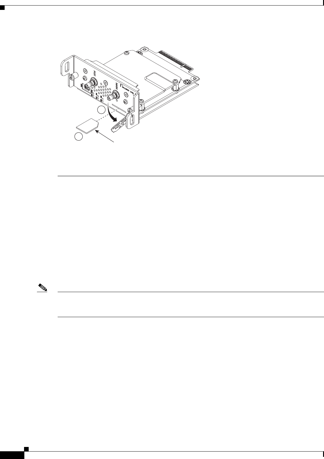
Step 2 Insert the SIM card with the key (notch) positioned on the right-hand side. The SIM card will come in
contact with the metal contacts in the socket.
18
Cisco Connected Grid 3G Module Installation and Configuration Guide
OL-25991-01
Installing and Removing the 3G Module
Figure 5 Installing the SIM Socket
Step 3 Firmly insert the card until it clicks into place.
Step 4 Rotate the cover back in place and secure by tightening the screw.
Removing the SIM Card (GSM Module)
To remove the SIM card, open the cover press the card and it will eject. Remove the card and replace the
cover.
Installing and Removing the 3G Module
Some Cisco Connected Grid 2G/3G Wireless Connected Grid Modules are installed into the host router
at the factory.
Note After replacing or installing a module in the router, you must update the label (on the router exterior)
that lists the module types contained in the router. The label must list the FCC ID number and the IC
Certification number for each module installed in the router.
Before You Begin Installation
Before installing the module, verify that the following guidelines have been met:
• Clearance to the I/O-side view is such that the LEDs can be easily read.
• Cabling is away from sources of electrical noise, such as radios, power lines, and fluorescent
lighting fixtures. Make sure that the cabling is away from other devices that might damage the
cables.
• Airflow around the switch module and through the vents is unrestricted.
• Temperature around the unit does not exceed 140°F (60° C). If the switch module is installed in a
closed or multi-rack assembly, the temperature around it might be higher than normal room
temperature.
Key
1
2
283960
19
Cisco Connected Grid 3G Module Installation and Configuration Guide
OL-25991-01
Installing and Removing the 3G Module
• Relative humidity around the switch module does not exceed 95 percent (non-condensing).
• Altitude at the installation site is not higher than 10,000 feet.
• For 10/100 and 10/100/1000 fixed ports, cable lengths from the switch module to connected devices
are not longer than 328 feet (100 meters).
Installation Warning Statements
This section includes the basic installation warning statements. Translations of these warning statements
appear in the Regulatory Compliance and Safety Information for Cisco Connected Grid Router 1000
Series Routers documents.
Warning
This unit is intended for installation in restricted access areas. A restricted access area can be
accessed only through the use of a special tool, lock and key, or other means of security.
Statement 1017
Warning
Only trained and qualified personnel should be allowed to install, replace, or service this equipment.
Statement 1030
Warning
To prevent the system from overheating, do not operate it in an area that exceeds the maximum
recommended ambient temperature of:
140°F (60°C)
Statement 1047
Warning
This equipment is supplied as “open type” equipment. It must be mounted within an enclosure that is
suitably designed for those specific environmental conditions that will be present and appropriately
designed to prevent personal injury resulting from accessibility to live parts. The interior of the
enclosure must be accessible only by the use of a tool.
The enclosure must meet IP 54 or NEMA type 4 minimum enclosure rating standards.
Statement 1063
Warning
This equipment is intended to be grounded to comply with emission and immunity requirements.
Ensure that the switch functional ground lug is connected to earth ground during normal use.
Statement 1064
Warning
To prevent airflow restriction, allow clearance around the ventilation openings to be at least: 1.75 in.
(4.4 cm)
Statement 1076
20
Cisco Connected Grid 3G Module Installation and Configuration Guide
OL-25991-01
Installing and Removing the 3G Module
Installing the 3G Module
To install the module into the router:
Caution The module can NOT be hot swapped—to install the module, you must first power down the host router.
Step 1 Before you install the Cisco Connected Grid 3G Module into the host CGR 1240 router, you must power
down the router as described in the Hardware Installation Guide of your router.
Step 2 Insert the module into the slot. (CGR 1120 and CGR 1240 shown.)
Step 3 Using a screwdriver, secure the two captive screws into place. Tighten to 5 to 8 pound-force inches
(lbf-in.).
Removing the Module
To remove the module from a router:
Caution The module can NOT be hot swapped—to install the module, you must first power down the host router.
Step 1 Before you remove the Cisco Connected Grid 3G Module from the host CGR 1240 router, you must
power down the router as described in the Hardware Installation Guide of your router.
283961
283962

21
Cisco Connected Grid 3G Module Installation and Configuration Guide
OL-25991-01
Regulatory and Compliance Information
Step 2 Using a screwdriver, loosen the two captive screws on the Cisco Connected Grid 3G Module.
Step 3 Gently pull the module out of the slot.
Regulatory and Compliance Information
For regulatory compliance and safety information for the module, refer to the Connected Grid Router
2000 Series Regulatory Compliance and Safety Information document.
http://www.cisco.com/en/US/docs/routers/access/2000/CGR2010/hardware/rcsi/rcsiCGR2000series.html
Software Overview
This section covers the following topics:
• 3G Overview, page 21
• UMTS/GSM Data Network Overview, page 22
• CDMA Data Network Overview, page 23
3G Overview
3G is defined by the ITU (International Telecommunications Union-2000 (IMT-2000) as mobile radio
systems capable of supporting peak data rates of:
• 144 Kb/s or more in a large cell (where the users may be miles from the Base Stations) with high
speed vehicular users
• 384 Kb/s or more for urban small cells (where the user may be only a few city blocks from a Base
Station) with pedestrian users
• 2 Mb/s or more for indoor (or very small cells, where the user may be only a few hundred feet from
a Base Station) with primarily stationary users
Note On the Cisco Connected Grid Module—3G HSPA+/UMTS/GSM/GPRS/EDGE module
(CGM-3G-HSPA-A), the ping packet size limit is 1472 bytes.
22
Cisco Connected Grid 3G Module Installation and Configuration Guide
OL-25991-01
Software Overview
UMTS/GSM Data Network Overview
Global System for Mobile Communication (GSM) is the most widely used digital mobile phone system
and the de facto wireless telephone standard in Europe. It is based on the specification from European
Telecommunications Standards Institute (ETSI). Originally defined as a pan-European open standard for
a digital cellular telephone network to support voice, data, text messaging and cross-border roaming.
GSM is now one of the world's main 2G digital wireless standards.
GSM was primarily designed for voice and was circuit switched, but due to the popularity of cellular
networks and the great demand for data services, General Packet Radio Service (GPRS) was introduced
as a packet-switched data overlay over the GSM radio network. The radio and network resources of
GPRS are accessed only when data needs to be transmitted between the GPRS mobile user and the GPRS
network.
GSM models are based on 3GPP, and they support HSPA (High-Speed Uplink Packet Access (HSUPA)
and High-Speed Downlink Packet Access (HSDPA)), UMTS (Universal Mobile Radio Service), EDGE
(Enhanced Data Rates for Global Evolution), and GPRS.
GPRS introduced several new network nodes into the GSM architecture for packet switching, they form
the Mobile Packet Core. The Mobile Packet Core includes the Serving GPRS Support Node (SGSN) and
the GPRS Gateway Support Node (GGSN). The SGSN is the node which, in some ways, carries out the
same function as the Foreign Agent in Mobile IP—it tunnels IP packets towards the GGSN and detunnels
packets back from the GGSN. It also carries out mobility managed and billing. GGSN is the node that
carries out the role in the GPRS equivalent to the Home Agent in Mobile IP. The GGSN provides the
connectivity to the IP network and the SGSN, is responsible for IP address assignment, and is the default
router for the connected User Equipment (UE).
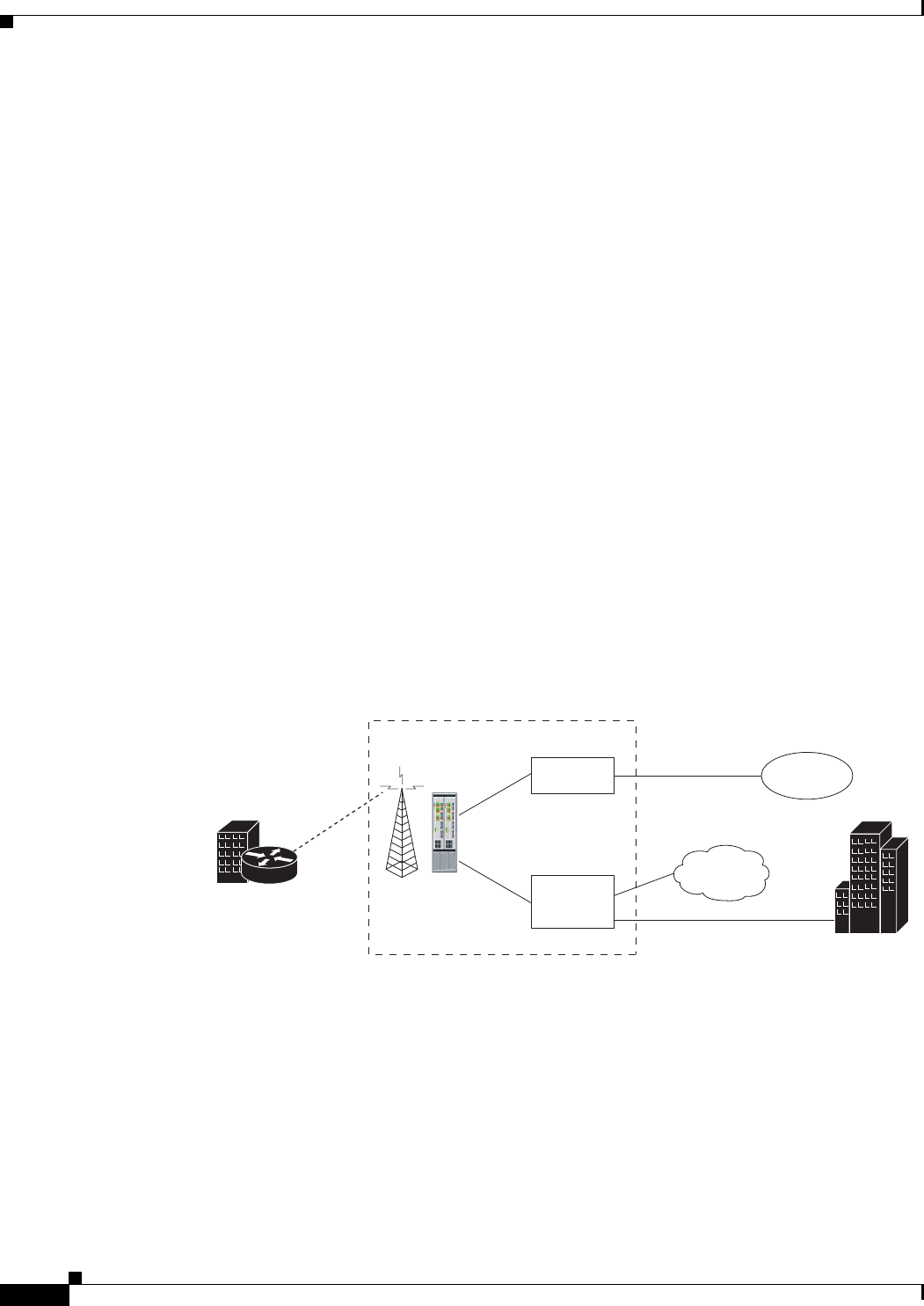
Figure 6 shows a GSM network and the network elements it contains.
Figure 6 GSM Network Overview
The Base Tranceiver Station (BTS) and Base Station Controller (BSC) are located at the Cell site and
are the common nodes for both voice and data services. They provide the radio or the physical layer
connectivity between the mobile user and the mobile network. As the BSC voice and data traffic get
MSC
GGSN/
PDSN
PSTN
Internet
BTS/BSC
Branch Office
with Cellular EHWIC
HQ
Voice
Data
Carrier Network
Leased Line
(MPLS, FR, Fiber)
BTS: Base Transceiver Stations
BSC: Base Station Controller
MSC: Mobile Switching Center
SGSN: Service GPRS Support Node
GGSN: Gateway SPRS Support Node
230351

23
Cisco Connected Grid 3G Module Installation and Configuration Guide
OL-25991-01
Software Overview
segregated, the voice traffic goes to the Mobile Switching Center (MSC), while the data traffic is sent to
the GGSN. From the GGSN, the data packets either go directly to the internet or they can be backhauled
to the customer data center for a VPN connection.
Universal Mobile Telecommunications System (UMTS) evolved from GSM and is a 3G wireless system
that delivers high-bandwidth data and voice services to mobile users. UMTS has a new air interface
based on Wideband Code Division Multiple Access (W-CDMA) and an IP core network based on
general-packet radio service (GPRS). The nodes in a UMTS network are almost the same as that of a
GSM/GPRS network. BTS and BSC have been renamed to Node B and Radio Network Controller
(RNC), respectively.
UMTS addresses the growing demand of mobile and Internet applications for new capacity in the
overcrowded mobile communications sky. The new network increases transmission speed to 2 Mbps per
mobile user and establishes a global roaming standard.
UMTS (Universal Mobile Telecommunication System) (W-CDMA) is standardized by 3GPP and offers
the following:
• W-CDMA radio access technology, in addition to the existing GSM and GPRS radio access
networks.
• W-CDMA uses 5 MHz bandwidth radio carriers. Up to 384kb/s initially. Capable of 2 Mb/s, but not
offered commercial yet.
• HSPA is an upgrade to W-CDMA (includes HSDPA (High Speed Downlink Packet Access) and
HSUPA (High-Speed Uplink Packet Access).
–
HSDPA:Various categories support up to 10 Mb/s
–
HSUPA:uplink speed up to 5.76 Mb/s
High Speed Packet Access (HSPA) is a collection of two mobile protocols—High Speed Downlink
Packet Access (HSDPA) and High Speed Uplink Packet Access (HSUPA)—that extends and improves
the performance of existing WCDMA/UMTS protocols. HSDPA and HSUPA provide increased
performance by using improved modulation schemes and by refining the protocols by which 3G modem
and base stations communicate.
These improvements lead to a better utilization of the existing radio bandwidth provided by WCDMA.
HSPA improves the end-user experience by increasing peak data rates of up to 14 Mbit/s in the downlink
and 5.76 Mbit/s in the uplink. It also reduces latency and provides up to five times more system capacity
in the downlink and up to twice as much system capacity in the uplink, reducing the production cost per
bit compared to original WCDMA protocols.
CDMA Data Network Overview
The Code Division Multiple Access (CDMA) is a digital cellular network developed to deliver
high-speed and improved wireless data service through increased capacity by allowing users to share a
band of frequencies. CDMA is being adopted by many administrators for cellular networks due to its
greater throughput which is six times that of Time Division Multiple Access (TDMA-) or Frequency
Division Multiple Access (FDMA)-based systems.
A typical CDMA network includes terminal equipment, mobile termination, base transceiver station
(BTS), base station controller (BSC), packet data serving node (PDSN), and other data network entities.
The PDSN is the interface between a BSC and a internet gateway.
A typical CDMA network includes a PDSN and a branch office with the 3G wireless Modular and Fixed
Cisco ISRs. The branch office connects to a radio tower and a BTS. The BTS connects to a BSC, which
contains a component called the packet control function (PCF). The PCF communicates with the Cisco
PDSN for data communication and with the mobile switching center (MSC) for voice.

24
Cisco Connected Grid 3G Module Installation and Configuration Guide
OL-25991-01
Configuring the Module
CDMA technology uses spread radio spectrum transmission with concurrent multiple access by dividing
the spectrum shared by multiple users by using channels using unique codes. These codes are filtered by
the receiver using a correlator that accepts only signals (streams of bits) from the desired code channel.
CDMA also employs graceful signal degradation, multipath resistance, inherent frequency diversity, and
interference rejection.
Evolution-Data Optimized (EVDO), also known as 1xEVDO, is a telecommunications standard that
employs the use of multiplexing, CDMA, and TDMA. EVDO was standardized by 3GPP2
(3rd-Generation Partnership Project 2), the global 3G wireless standard specification, and has been
adopted by many mobile service providers who had been previously using CDMA. 1x EVDO
(1x Evolution Data Optimized) supports up to 2.4 Mb/s downlink and 153.6 Kb/s uplink in Revision 0,
while Revision A supports 3.1 Mb/s downlink and 1.8 Mb/s uplink.
CDMA2000, also known as CDMA2000 1x and as 1xRTT (1 times Radio Transmission Technology),
had evolved from IS-95 (cdmaOne), the first CDMA-based digital cellular (2D) standard, with which
CDMA2000 is backward-compatible. The suffix 1x means that it uses the same 1.25 MHz bandwidth as
IS-95 has always used and supports up to 144 Kb/s, initially. CDMA2000 was standardized by the
3GPP2 committee and is based on the standards of CDMA2000 1X, CDMA2000 EVDO Rel. 0,
CDMA2000 EVDO Rev. A, and CDMA2000 EVDO Rev. B.
The Cisco Connected Grid Module—3G EVDO Rev A/0/1xRTT module is based on 3GPP2 and
supports the CDMA2000 EVDO Rev A and Rel. 0, and CDMA2000 1x operating standards.
Configuring the Module
The module is configured using the system software. This section covers the following topics:
• Prerequisites, page 25
• Configuration Restrictions, page 25
• Configuring the GSM Module, page 25
• Configuring the CDMA Module, page 26
• show Commands, page 27
• Data Account Provisioning, page 30
• GSM Cellular Interface Configuration, page 31
• CDMA Cellular Interface Configuration, page 32
• Configuring WAN Backhaul Redundancy, page 33
Note The 3G module can be plugged into slots 3 to 6 of Cisco 1240 Connected Grid Router, therefore the
interface names used to configure the module can be 3/1, 4/1, 5/1, or 6/1. Interface 3/1 is used in the
configuration examples in this section.
Note The 3G module can be plugged into slots 3 or 4 of Cisco 1120 Connected Grid Router, therefore the
interface names used to configure the module can be 3/1 or 4/1. Interface 3/1 is used in the configuration
examples in this section.

25
Cisco Connected Grid 3G Module Installation and Configuration Guide
OL-25991-01
Configuring the Module
Prerequisites
To configure the 3G module, you must meet the following requirements:
• Have 2G/3G network coverage where your router will be physically located. For a complete list of
supported carriers, see the product data sheet.
• Subscribe to a service plan with a wireless service provider and obtain a SIM card.
• Install the SIM card before configuring the 3G module. For instructions on how to install the SIM
card, see the section, Installing the SIM Card (GSM Module), page 17.
Configuration Restrictions
The following restrictions apply to configuring the Cisco Connected Grid 3G Module:
• Data connection can be originated only by the module.
• Throughput: Due to the shared nature of wireless communications, the experienced throughput
varies depending on the number of active users or congestion in a given network.
• Cellular networks have higher latency compared to wired networks. Latency rates depend on the
technology and carrier. Latency may be higher because of network congestion.
• Any restrictions that are a part of the terms of service from your carrier.
Configuring the GSM Module
Step 1: Creating a GSM Profile
Use the cellular 3/1 gsm profile command to configure a GSM profile:
Router# cellular 3/1 gsm profile create 1 <Access Point Name> [<authentication type
<username> <password>]
• Use <authentication type> if username and password is configured.
• Use <username> if required by your carrier.
• Use <password> if required by your carrier.
See also GSM Cellular Interface Configuration, page 31.
Step 2: Configuring a Chat Script
Use the chat-script command to configure a GSM chat script:
Router(config)# chat-script <chat-script name> PROFILE1

26
Cisco Connected Grid 3G Module Installation and Configuration Guide
OL-25991-01
Configuring the Module
Step 3: Configuring Dialer Parameters
Use the dialer commands to configure dialer parameters:
Router(config)# interface dialer 1
Router(config-if)# dialer pool 1
Router(config-if)# dialer string <chat-script name>
Router(config-if)# dialer persistent
Router(config-if)# no shutdown
Note To unconfigure dialer persistent, you must delete the profile by using the command, cellular 3/1 gsm
profile delete 1.
Step 4: Configuring Cellular Parameters
Use the dialer pool-member command to configure cellular parameters:
Router(config)# interface cellular 3/1
Router(config-if)# dialer pool-member 1
Step 5: Saving Configuration
Use the shutdown and no shutdown commands to save configuration on the interface:
Router(config)# interface cellular 3/1
Router(config-if)# shutdown
Router(config-if)# no shutdown
GSM Unconfiguration
All commands, except dialer persistent, can be unconfigured with the no option. The dialer persistent
profile must be deleted with the command, cellular 3/1 gsm profile delete 1.
See also Step 3: Configuring Dialer Parameters, page 26.
Configuring the CDMA Module
Step 1: Configuring a Chat Script
Use the chat-script command to configure a GSM chat script:
Router(config)# chat-script <chat-script name> ATDT#777
Step 2: Configuring Dialer Parameters
Use the dialer commands to configure dialer parameters:
Router(config)# interface dialer 1
Router(config-if)# dialer pool 1
Router(config-if)# dialer string <chat-script name>
Router(config-if)# dialer persistent
Router(config-if)# no shutdown

27
Cisco Connected Grid 3G Module Installation and Configuration Guide
OL-25991-01
Configuring the Module
Step 3: Configuring PPP Encapsulation
Use the feature ppp command to configure PPP encapsulation:
Router(config)# feature ppp
Step 4: Configuring Cellular Parameters
Use the dialer pool and encapsulation ppp commands to configure cellular parameters:
Router(config)# interest cellular 3/1
Router(config-if)# dialer pool-member 1
Router(config-if)# encapsulation ppp
Step 5: Saving Configuration
Use the shutdown and no shutdown commands to save configuration on the interface:
Router(config)# interface cellular 3/1
Router(config-if)# shutdown
Router(config-if)# no shutdown
show Commands
To view your configurations, use the following show commands:
• show ip interface brief
• show interface cellular 3/1
• show cellular 3/1 ?
–
all—Display cellular information
–
connection—Display cellular connection status
–
hardware—Display cellular hardware information
–
leds—Display LED information
–
network—Display cellular network information
–
profile—Display cellular interface profile
–
radio—Display cellular radio information
–
band—Display radio band information
show cellular 3/1 all (GSM Module)
Shows consolidated information about the modem, profiles created, radio signal strength, network
security, and so on.
Note The RSSI should be better than -90 dBm for steady and reliable connection.
Router# show cellular 3/1 all
Hardware Information
====================

28
Cisco Connected Grid 3G Module Installation and Configuration Guide
OL-25991-01
Configuring the Module
Modem Firmware Version = T1_0_3_2AP R361 CNSZXD00000061 2011/04/15 17:40:48
Modem Firmware Built = 04/15/11
Modem Hardware Version = 1.0
International Mobile Subscriber Identity (IMSI) = 0123456063
International Mobile Equipment Identity (IMEI) = 353567040032469
<-- Unique identifier for module
Factory Serial Number (FSN) = CC3291006141001
Modem status = Online
Current Modem Temperature = 33 deg C
Current Temperature State = Normal
Profile Information
===================
--- Profile 1 details ---
Status = Activated
Default: Yes
PDP Type: IPv4
Profile IP: 192.0.2.0 <-- Profile details stored on the modem
Profile APN: isp.cingular
Authentication: CHAP
Profile UserName:
Profile Password:
Data Connection Information
===========================
Data Transmitted = -1603896208 bytes
Data Received = 208880986 bytes
Profile 1, Packet Session Status = ACTIVATED <-- State of the connection
Network Information
===================
Modem status = Online
Service status = Normal
Service type = Combined
Country Initials = 1
Network name =
MCC = 1, MNC = 1 <-- Mobile country code, mobile network code
Location Area Code (LAC) = 128
Routing Area Code (RAC) = 0
Cell ID = 1
Primary Scrambling Code = 100
PLMN Selection = Automatic
Radio Information
=================
Current band = WCDMA_I_IMT2000 <-- Current band/channel/RSSI
Radio power mode = On
Channel number = 10563
Band selected = Auto
Current RSSI = -56 dBm
Band Information
================
Number of bands: 5 <-- Bands supported by the modem are listed below

29
Cisco Connected Grid 3G Module Installation and Configuration Guide
OL-25991-01
Configuring the Module
Band 1: GSM EGSM DCS
Band 2: Unknown Band Group
Band 3: GSM ALL
Band 4: Unknown Band Group
Band 5: AUTO BAND
show cellular 3/1 all (CDMA Module)
Shows consolidated information about the modem, profiles created, radio signal strength, network
security, and so on.
Note The RSSI should be better than -90 dBm for steady and reliable connection.
Router# show cellular 3/1 all
Hardware Information
====================
Modem Firmware Version = p2813301
Modem Firmware Built = 06-24-10
Modem Hardware Version = MC5728V Rev 1.0
International Mobile Subscriber Identity (IMSI) = 5555550032
Electronic Serial Number (ESN) = 60D22706
<-- Unique identifier for module
Modem status = Online
Current Modem Temperature = 31 deg C
Current Temperature State = Normal
Profile Information
===================
Electronic Serial Number (ESN) = 60D22706 <-- Unique identifier for module
Activation Status = active
Activation Date = 20110925
Phone Number (MDN) = 5555550213
Number of data profiles configured: 1
Current Active Data Profile: 1
NAI (Network Access Identifier) = 5555550213@vzw3g.com
MN-HA SS = enabled
MN-HA SPI = 300
MN-AAA SS = enabled
MN-AAA SPI = 2
Reverse Tunneling Preference = enabled
Home Address = 0.0.0.0
Primary Home Agent Address = 255.255.255.255
Secondary Home Agent Address = 255.255.255.255
Data Connection Information
===========================
Phone Number of outgoing call = 5555550213
Data Transmitted = 14041 bytes
Data Received = 14041 bytes
Network Information
===================

30
Cisco Connected Grid 3G Module Installation and Configuration Guide
OL-25991-01
Configuring the Module
Current Roaming Status = Not Roaming
Current Idle Digital Mode = No Service
Current System Identifier (SID) = 40
Current System Identifier (NID) = 0
Serving Base Station Longitude = 0 deg 0 min 0 sec
Serving Base Station Latitude = 0 deg 0 min 0 sec
Radio Information
=================
Current band = CDMA_CLASS1,CDMA_CLASS1 <-- Current band/channel/RSSI
Radio power mode = On
Channel number = 548
Current RSSI = -82 dBm
Data Account Provisioning
Note For the Cisco Connected Grid 3G Module, the numbering is 3/1 for all commands.
Note To provision your modem, you must have an active wireless account with a service provider and a SIM
card installed.
To provision your data account, see the following topics:
• Verifying Signal Strength and Service Availability, page 30
• Activating the Module Using OTASP (CDMA Module), page 31
Verifying Signal Strength and Service Availability
To verify the signal strength and service availability on your modem, use the following commands in
privileged EXEC mode. See also show Commands, page 27.
• show cellular3/1 network
• show cellular 3/1 radio
• show cellular 3/1 profile
• show cellular 3/1 all
• show cellular 3/1 led
31
Cisco Connected Grid 3G Module Installation and Configuration Guide
OL-25991-01
Configuring the Module
DETAILED STEPS
Activating the Module Using OTASP (CDMA Module)
To activate the module using Over-The-Air Service Provisioning (OTASP), use the cellular 3/1 cdma
activate otasp *22899 command.
Note Do not hit a Enter (carriage return) until provisioning is complete—you will see “Over the air
provisioning complete; Result = Success.” See below.
Router# cellular 3/1 cdma activate otasp *22899
Beginning OTASP activation
OTASP number is *22899
Router#
<-- Do not hit Enter key-- provisioning is in process.
OTA State = SPL unlock, Result = Successprovising
OTA State = Profile downloaded, Result = Success
OTA State = MDN downloaded, Result = Success
OTA State = Parameters committed to NVRAM, Result = Success
Over the air provisioning complete; Result = Success
<-- Activation successful. Hit Enter to return to prompt
Router#
To verify that the account has been provisioned and the modem has been activated, use the show cellular
3/1 profile command in EXEC mode:
Router# show cellular 3/1 profile
* - Default profile
GSM Cellular Interface Configuration
To configure the cellular interface:
Step 1 Create a profile on the interface 3/1 using the cellular command:
Router# cellular 3/1 gsm profile create 1 <Access Point Name> [<username> <password>]
Step 2 Configure terminal:
Step Command Purpose
Step 1 show cellular 3/1 network Displays information about the carrier network, cell site, and
available service.
Step 2 show cellular 3/1 radio Shows the radio signal strength.
Note The RSSI should be better than -90 dBm for steady
and reliable connection.
Step 3 show cellular 3/1 profile Shows information about the modem data profiles created.
Step 4 show cellular 3/1 security Shows the security information for the modem, such as SIM
and modem lock status.
Step 5 show cellular 3/1 all Shows consolidated information about the modem, profiles
created, radio signal strength, network security, and so on.

32
Cisco Connected Grid 3G Module Installation and Configuration Guide
OL-25991-01
Configuring the Module
Router# configure terminal
Step 3 Create a chat script using the chat-script command and assign it to your profile:
Router(config)# chat-script <chat-script name> PROFILE1 #
Step 4 Configure dialer parameters on the interface by using the interface command to enter interface
configuration mode, and the dialer command to configure persistent dialer mode.
Router(config)# interface dialer 1
Router(config-if)# dialer pool 1
Router(config-if)# dialer string <chat-script name>#
Router(config-if)# dialer persistent
Step 5 Configure cellular parameters on the interface by using the interface and dialer commands:
Router(config)# interface cellular 3/1
Router(config-if)# dialer pool-member 1
Step 6 Shutdown and no shut the interface using the shutdown and no shutdown commands:
Router(config)# interface cellular 3/1
Router(config-if)# shutdown
Router(config-if)# no shutdown
GSM Dialer Persistent Unconfiguration
All commands can be unconfigured with the no option, however, the dialer persistent configuration
condition cannot be unconfigured. Therefore, to remove dialer persistent, the profile must be deleted
with the cellular configuration command as follows:
Router# cellular 3/1 gsm profile delete 1
CDMA Cellular Interface Configuration
The following example shows how to configure the cellular interface:
Step 1 Configure a chat script using the chat-script command:
Router(config)# chat-script <chat-script name> ATDT#777 <-- ATDT777# is the chat-script name.
Step 2 Configure dialer parameters by using the dialer command:
Router(config)# interface dialer 1
Router(config-if)# dialer pool 1
Router(config-if)# dialer string ATDT777#
Router(config-if)# dialer persistent
Step 3 Configure PPP encapsulation by using the feature command:
Router(config)# feature ppp
Step 4 Configure the cellular parameters by using the encapsulation command:
Router(config)# interface cellular 3/1
Router(config-if)# dialer pool-member 1
Router(config-if)# encapsulation ppp
Step 5 Save changes by issuing shutdown and no shutdown on the interface:

33
Cisco Connected Grid 3G Module Installation and Configuration Guide
OL-25991-01
Configuration Example
Router(config)# interface cellular 3/1
Router(config-if)# shutdown
Router(config-if)# no shutdown
Configuring WAN Backhaul Redundancy
For information on configuring WAN backhaul redundancy, see Cisco 1000 Series Connected Grid
Routers Unicast Routing Software Configuration Guide.
Configuration Example
The following example shows a configuration that includes information on TACACS+ security, OSPF
(Open Shortest Path First), OSPF v3, DHCP (Dynamic Host Configuration Protocol), DHCP v6, a
tunnel, virtual tunnel, QoS, Internet Protocol Security (IPSec), a static IP address when a tunnel interface
(3/1) is configured, the interfaces (Ethernet, serial, cellular, WPAN, and WiFi), dialer, and chat script.
Router# show running-configuration
!Command: show running-config
!Time: Sun Aug 14 00:36:25 2011
version 5.2(1)
hostname Router
vdc Router id 1
limit-resource vlan minimum 16 maximum 4094
limit-resource vrf minimum 2 maximum 4096
limit-resource port-channel minimum 0 maximum 768
limit-resource u4route-mem minimum 9 maximum 9
limit-resource u6route-mem minimum 24 maximum 24
limit-resource m4route-mem minimum 58 maximum 58
limit-resource m6route-mem minimum 8 maximum 8
feature privilege
feature tacacs+
feature crypto ike
crypto ike domain ipsec
policy 10
group 1
lifetime seconds 660
identity hostname
feature ospf
feature ospfv3
feature dhcp
feature tunnel
feature crypto ipsec virtual-tunnel
feature dhcpv6
feature ppp
username adminbackup password 5 ! role network-operator
username admin password 5 $1$fMmnWu6t$Aawk/sH5wmErCjCwnxeyb. role network-admin
enable secret 5 $1$454cdd6$a08d10dc3fdb2f6f
no password strength-check
ip domain-lookup
tacacs-server host 4.4.4.5 key 7 "fewhg"
aaa group server tacacs+ tactical
server 4.4.4.5

34
Cisco Connected Grid 3G Module Installation and Configuration Guide
OL-25991-01
Configuration Example
crypto key param rsa label IPSEC_IDENTITY_BLUE modulus 2048 exportable
crypto ca trustpoint IPSEC_IDENTITY_BLUE
rsakeypair IPSEC_IDENTITY_BLUE 2048
revocation-check none
class-map type qos match-all ignore
match precedence 0
class-map type qos match-all packet
match packet length 1500
class-map type qos match-all critical
match dscp 46
class-map type qos match-all matchall
match precedence 1
match dscp 10
class-map type qos match-any matchany
match dscp 10,26
class-map type qos match-all priority
match precedence 3
policy-map type qos ignore
class ignore
set dscp 1
policy-map type qos packet
class packet
set precedence 5
policy-map type qos critical
class critical
set dscp 10
policy-map type qos matchall
class matchall
set precedence 5
policy-map type qos matchany
class matchany
set dscp 46
policy-map type qos priority
class priority
set dscp 46
priority level 3
copp profile strict
snmp-server user admin auth md5 0x5f66c5f7cde8de86eecb2008de9126f8 priv 0x5f66c5
f7cde8de86eecb2008de9126f8 localizedkey engineID 128:0:0:9:3:0:34:189:224:46:129
rmon event 1 log trap public description FATAL(1) owner PMON@FATAL
rmon event 2 log trap public description CRITICAL(2) owner PMON@CRITICAL
rmon event 3 log trap public description ERROR(3) owner PMON@ERROR
rmon event 4 log trap public description WARNING(4) owner PMON@WARNING
rmon event 5 log trap public description INFORMATION(5) owner PMON@INFO
vrf context test
vrf context management
crypto ipsec profile MyProfile
set transform-set MyTransformSet
set pfs group1
set security-association lifetime seconds 120
set security-association lifetime kilobytes 2560
crypto ipsec transform-set MyTransformSet esp-gcm 256
vlan 1
no ip dhcp relay
interface Tunnel0
ip address 4.0.0.1/24
tunnel mode ipsec ipv4
tunnel source cellular3/1
tunnel destination 192.168.168.2
tunnel protection ipsec profile MyProfile
no shutdown

35
Cisco Connected Grid 3G Module Installation and Configuration Guide
OL-25991-01
Configuration Example
interface Tunnel1
ipv6 address 2001:b:b:bc::1/64
ipv6 mld join-group ff38:40:2011:dead:beef:cafe:0:1
ipv6 router ospfv3 1 area 0.0.0.0
tunnel source Tunnel0
tunnel destination 4.0.0.2
no shutdown
ipv6 dhcp relay destination 2001:a:b:c::100
interface Tunnel5
no shutdown
interface Ethernet2/1
mac-address 0022.bde0.3201
ip address 2.12.54.10/16
no shutdown
interface Ethernet2/2
mtu 1496
mac-address 0022.bde0.3202
ip address 172.27.161.54/25
ipv6 address 2001:dead:beef:cafe::2/64
no shutdown
interface Ethernet2/3
mtu 1496
mac-address 0022.bde0.3203
interface Ethernet2/4
mtu 1496
mac-address 0022.bde0.3204
interface Ethernet2/5
mtu 1496
mac-address 0022.bde0.3205
interface Ethernet2/6
mtu 1496
mac-address 0022.bde0.3206
interface Ethernet2/7
mtu 1496
mac-address 0022.bde0.3207
interface Ethernet2/8
mtu 1496
mac-address 0022.bde0.3208
no shutdown
interface serial1/1
physical-layer async
interface serial1/2
physical-layer async
interface cellular3/1
no shutdown
encapsulation ppp
dialer pool-member 1
interface wimax5/1
shutdown
no description

36
Cisco Connected Grid 3G Module Installation and Configuration Guide
OL-25991-01
Additional References
pkm version none
pkm crypto algorithm none
interface wpan4/1
no shutdown
ipv6 address 2011:dead:beef:cafe::0/64
rpl prefix 2011:dead:beef:cafe::0/64
ipv6 dhcp relay client-interface
interface wifi2/1
clock timezone PST -8 0
line console
line vty
boot kickstart bootflash:/cgr1000-uk9-kickstart.5.2.0.CG1.0.194.SSA.gbin sup-1
boot system bootflash:/cgr1000-uk9.5.2.0.CG1.0.194.SSA.gbin sup-1
router ospfv3 1
address-family ipv6 unicast
ip route 0.0.0.0/0 cellular3/1
ip route 223.255.0.0/16 2.12.0.1
ipv6 route 2001:420:7bf:5f::/64 Tunnel1
ipv6 route 2001:a:b:c::/64 Tunnel1
line tty 1
device-role dce
line tty 2
device-role dce
interface Dialer1
dialer persistent
dialer pool 1
dialer string gsm
chat-script gsm PROFILE1
cgdm
registration start trustpoint ://2001:420:7bf:5f::800:9121
no logging console
Additional References
Consult the following resources for related information about the 3G module or for technical assistance.
Hardware Overview and Installation Documents
• Cisco Connected Grid Modules
http://www.cisco.com/en/US/products/ps10984/prod_module_series_home.html
• Cisco CGR 1240 Hardware Installation Guide
• Cisco CGR 1120 Hardware Installation Guide
• Cisco CGS1240 Getting Started Guide

37
Cisco Connected Grid 3G Module Installation and Configuration Guide
OL-25991-01
Technical Assistance
Supported Cisco Antennas and Accessories Documents
• Cisco 3G Omnidirectional Outdoor Antenna (3G-ANTM-OUT-OM)
http://www.cisco.com/en/US/docs/routers/access/wireless/hardware/notes/ant3gom.html
• Cisco Multiband Omnidirectional Panel-Mount Antenna (3G-ANTM-OUT-LP)
http://www.cisco.com/en/US/docs/routers/access/wireless/hardware/notes/antcmLP.html
Cisco System Software Commands Documents
• Cisco Connected Grid Device Manager User Guide
• Cisco System Software
http://www.cisco.com/en/US/products/ps9372/tsd_products_support_series_home.html
• Configuring Cisco EHWIC-3G-EDVO-x
http://www.cisco.com/en/US/docs/routers/access/1800/1861/software/feature/guide/mrwls_evdo.html
• Cisco 1000 Series Connected Grid Routers Unicast Routing Software Configuration Guide
Regulatory, Compliance, and Safety Information
• Cisco Network Modules and Interface Cards Regulatory Compliance and Safety Information
http://www.cisco.com/en/US/docs/routers/access/interfaces/rcsi/IOHrcsi.html
Technical Assistance
The Cisco Support and Documentation website provides online resources to download documentation,
software, and tools. Use these resources to install and configure the software and to troubleshoot and
resolve technical issues with Cisco products and technologies. Access to most tools on the Cisco Support
and Documentation website requires a Cisco.com user ID and password.
http://www.cisco.com/cisco/web/support/index.html

38
Cisco Connected Grid 3G Module Installation and Configuration Guide
OL-25991-01
Troubleshooting and Diagnostics
Troubleshooting and Diagnostics
This section provides the necessary background information and resources available for troubleshooting
the 2G/3G Connected Grid module.
For LED descriptions, see Ports and LEDs, page 7.
• Debug Commands, page 38
• Modem AT Test Commands, page 38
• Checking Signal Strength, page 39
• Verifying Service Availability (GSM Module), page 39
• Successful Call Setup (GSM Module), page 41
• Retrieving the Electronic Serial Number, page 41
• Converting Hexadecimal ESN to Decimal Notation, page 42
Debug Commands
The following are sample output for the debug cellular commands:
Router# debug cellular ?
<0-10> Debug level
Router# debug cellpm ?
all All debugging
error Error cellpm debug
trace Trace cellpm debug
Router# debug chat ?
error Error chat debug
trace Trace chat debug
Router# debug dialer ?
all All debugging
error Error dialer debug
trace Trace dialer debug
Modem AT Test Commands
The following is the test cellular AT command.
Note CDMA Module: Accessing the AT commands will end the connection.
Router# test cellular 2/1 atcommands
ati
Device busy - issue +++ to abort connection before issuing AT commands
+++
NO CARRIER
ati
ati
Manufacturer: Sierra Wireless, Inc.
Model: MC5728V Rev 1.0 (5)
Revision: p2813301,10 [Jun 24 2010 12:18:30]
39
Cisco Connected Grid 3G Module Installation and Configuration Guide
OL-25991-01
Troubleshooting and Diagnostics
QCOM: SWI6085_FP.01.28
BOOT: SWI6085_PP.01.33.01 2010/06/24 15:02:12
APPL: SWI6085_PP.01.33.01 2010/06/24 15:02:12
USBD: SWI6085_GENERIC.00.01
USB VID: 0x1199 PID: 0x0028
ESN: 0x60D2271B
+GCAP: +CIS707-A, CIS-856, CIS-856-A, +MS, +ES, +DS, +FCLASS
SKU: 0x82BB5
OK
Exit <------ To return to the Console prompt.
Note To return to the Console prompt: Press exit.
Table 15 show useful AT commands:
Checking Signal Strength
If the Received Signal Strength Indication (RSSI) level is very low (for example, if it is less than -110
dBm), follow these steps:
Step 1 Check the antenna connection. Make sure the QMA connector is correctly threaded and tightened.
Step 2 If you are using a remote antenna, move the antenna cradle and check if the RSSI has improved.
Step 3 Contact your wireless service provider to verify that there is service availability in your area.
Verifying Service Availability (GSM Module)
The following is sample show cellular 3/1 all command output for a scenario where the antenna is
disconnected and a modem data profile has not been created.
The error in this case has been highlighted below:
Router# show cellular 3/1 all
Table 15 AT Commands
AT Command Description
AT!HSDCAT? To get programmed DPA Category
AT!HSUCAT? To get programmed UPA Category
AT+BAND? To find the band
AT+CPIN? To get SIM card status
AT!GSTATUS? Status
AT!SCACT=1,1 Connect to network
ATI Get hardware and software details of the modem

40
Cisco Connected Grid 3G Module Installation and Configuration Guide
OL-25991-01
Troubleshooting and Diagnostics
Hardware Information
====================
Modem Firmware Version = T1_0_3_2AP R361 CNSZXD00000061 2011/04/15 17:40:48
Modem Firmware Built = 04/15/11
Modem Hardware Version = 1.0
International Mobile Subscriber Identity (IMSI) = 345678901
International Mobile Equipment Identity (IMEI) = 357115040054053
Factory Serial Number (FSN) = CC3200115221007
Modem status = Online
Current Modem Temperature = 0 deg C
Current Temperature State = Normal
Profile Information
====================
* - Default profile <-- Indicates that no profile is present
Data Connection Information
===========================
Data Transmitted = 5616 bytes
Data Received = 9424 bytes
Profile 1, Packet Session Status = ACTIVATED
IP Address = 192.0.2.0
Network Information
===================
Current Service Status = No service, Service Error = None
<-- Indicates no service—not connected to
network
Current Service = Combined
Packet Service = None
Packet Session Status = Inactive
Current Roaming Status = Home
Network Selection Mode = Automatic
Country = USA, Network = Cinglr
Mobile Country Code (MCC) = 310
Mobile Network Code (MNC) = 380
Location Area Code (LAC) = 6042
Routing Area Code (RAC) = 255
Cell ID = 0
Primary Scrambling Code = 0
PLMN Selection = Automatic
Radio Information
=================
Current Band = None, Channel Number = 0
Current RSSI = -110 dBm <-- Indicates either no antenna or bad antenna, or out of network
Band Information
================
Number of bands: 5
Band 1: GSM EGSM DCS
Band 2: Unknown Band Group
Band 3: GSM ALL
Band 4: Unknown Band Group
Band 5: AUTO BAND

41
Cisco Connected Grid 3G Module Installation and Configuration Guide
OL-25991-01
Troubleshooting and Diagnostics
Successful Call Setup (GSM Module)
The following are the single-line debug output for key steps while establishing a successful connection.
Cellular Driver Started
The debug cellular trace command output provides the following output:
...
2009 Jan 1 07:53:37.201398 cellpm: Cellular start driver: ifindex 29180000
...
Modem is Enabled
The debug cellular trace command output provides the following output:
...
2009 Jan 1 07:53:37.232260 cellpm: Receive modem enabled notification
...
Chat Script Invoked
The debug chat trace command output provides the following output:
...
2009 Jan 1 07:53:37.265470 dialer: CHAT SCRIPT gsm1_x profile 1
...
Packet Session Activated Successfully
The debug cellular trace command output provides the following output:
...
2009 Jan 1 07:53:39.724489 cellpm: Send MTS - PKT SESS ACTIVATED to dialer
...
Stop Dialer Since Connection is Established
The debug dialer trace command output provides the following output:
...
2009 Jan 1 07:53:39.724766 dialer: Session activated. Dialer1 stop dialing
...
Retrieving the Electronic Serial Number
If your network provider requests the 11-digit decimal equivalent of your Electronic Serial Number
(ESN), you must retrieve your ESN, then convert it to decimal notation. See also, Converting
Hexadecimal ESN to Decimal Notation, page 42.
The ESN number is located directly on the modem label in hexadecimal notation. It can also be retrieved
using the Cisco IOS CLI using the show cellular 3/1 all command.
GSM Module Sample Output
The sample output below shows the IMEI number:
Router# show cellular 3/1 all
Hardware Information
====================
Modem Firmware Version = T1_0_3_2AP R361 CNSZXD00000061 2011/04/15 17:40:48

42
Cisco Connected Grid 3G Module Installation and Configuration Guide
OL-25991-01
Troubleshooting and Diagnostics
Modem Firmware Built = 04/15/11
Modem Hardware Version = 1.0
International Mobile Subscriber Identity (IMSI) = 0123456063
International Mobile Equipment Identity (IMEI) = 353567040032469
<-- Unique identifier for module
Factory Serial Number (FSN) = CC3291006141001
Modem status = Online
Current Modem Temperature = 33 deg C
Current Temperature State = Normal
GSM Module Sample Output
The sample output below shows the ESN number:
Router# show cellular 3/1 all
Hardware Information
====================
Modem Firmware Version = p2813301
Modem Firmware Built = 06-24-10
Modem Hardware Version = MC5728V Rev 1.0
International Mobile Subscriber Identity (IMSI) = 4082280032
Electronic Serial Number (ESN) = 60D22706
<-- Unique identifier for module
Modem status = Online
Current Modem Temperature = 31 deg C
Current Temperature State = Normal
Converting Hexadecimal ESN to Decimal Notation
If your network provider requests the 11-digit decimal equivalent of your Electronic Serial Number
(ESN), you must retrieve your ESN, then convert it to decimal notation. See also, Retrieving the
Electronic Serial Number, page 41.
To convert the ESN number from hexadecimal notation to decimal notation:
Step 1 Start with the 8-digit HEX ESN # obtained from the label or using CLI, for example 0x603C9854. This
number consists of two parts:
• 0x60—Serial number
• 3C9854—Manufacturer’s code
Step 2 Convert manufacturer’s code to decimal as shown:
Hexadecimal 0x60 equals decimal 96.
If the decimal value is two digits only, prepend it with a zero to expand it to three digits.
Manufacturer’s code is thus 096.
Step 3 Convert the serial number to decimal, as shown in the example below:
Hexadecimal 0x3C9854 equals decimal 3971156.
If decimal value is less than 8 digits, add enough zeros to make it into an 8 digit number.
Serial number is thus 03971156.
Step 4 To obtain complete 11-digit decimal ESN notation, combine manufacturer code and serial number:
Manufacturer code: 096

43
Cisco Connected Grid 3G Module Installation and Configuration Guide
OL-25991-01
Troubleshooting and Diagnostics
Serial #: 03971156
Decimal ESN: 09603971156
Cisco and the Cisco Logo are trademarks of Cisco Systems, Inc. and/or its affiliates in the U.S. and other countries. A listing of Cisco's trademarks
can be found at www.cisco.com/go/trademarks. Third party trademarks mentioned are the property of their respective owners. The use of the word
partner does not imply a partnership relationship between Cisco and any other company. (1005R)
Any Internet Protocol (IP) addresses and phone numbers used in this document are not intended to be actual addresses and phone numbers. Any
examples, command display output, network topology diagrams, and other figures included in the document are shown for illustrative purposes only.
Any use of actual IP addresses or phone numbers in illustrative content is unintentional and coincidental.
No combinations are authorized or intended under this document.
© 2011 Cisco Systems, Inc. All rights reserved.

44
Cisco Connected Grid 3G Module Installation and Configuration Guide
OL-25991-01
Troubleshooting and Diagnostics