Delta Electronics orporated DN-715 NoteBook User Manual MANUAL CHAP 1
Delta Electronics Incorporated NoteBook MANUAL CHAP 1
UserManual.wiki
>
Delta Electronics orporated
>
DN-715 User Manual
>
MANUAL CHAP 1
Contents
1.
USER MANUAL CHAP0
2.
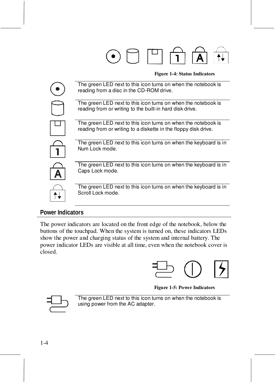
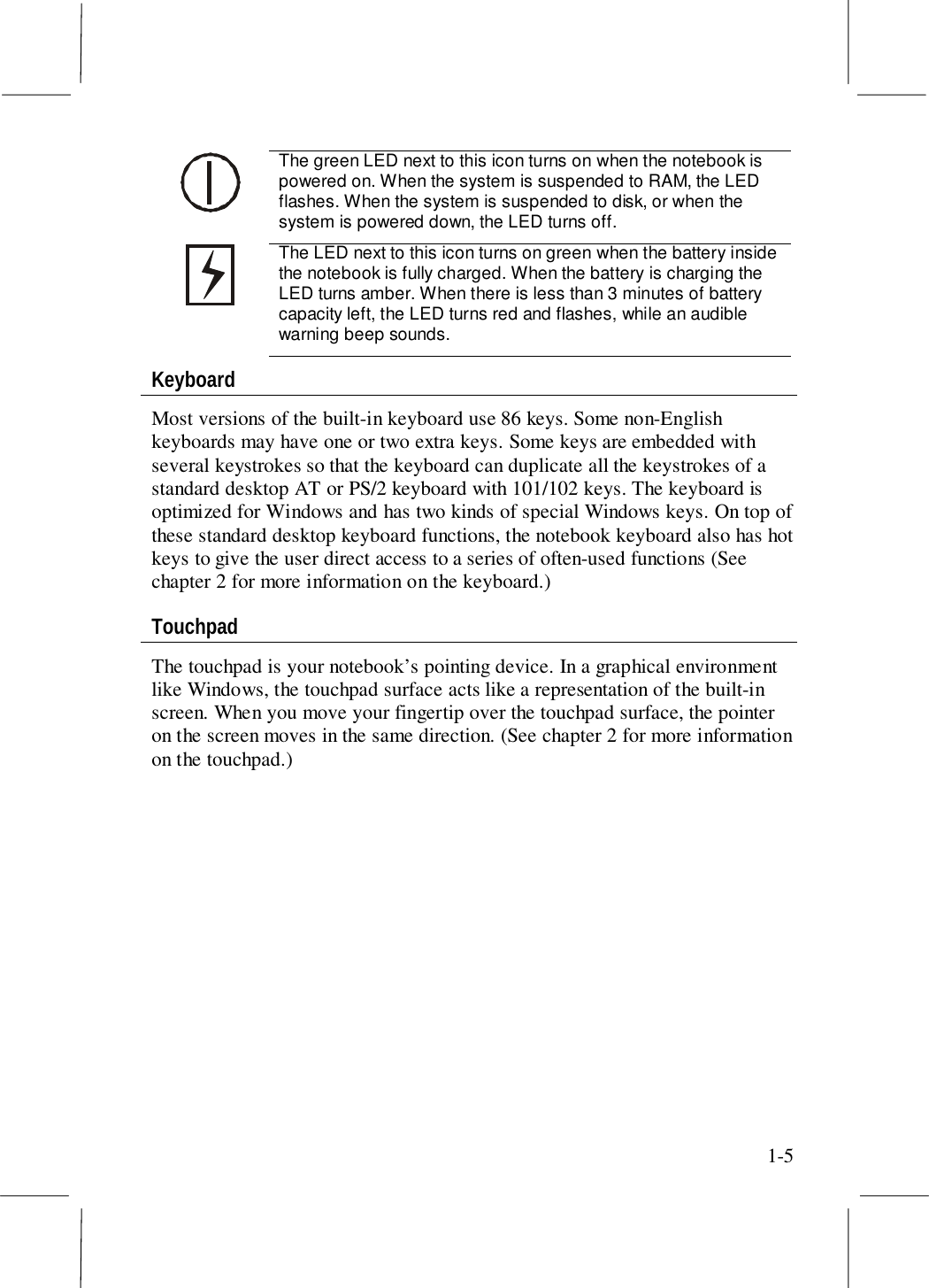
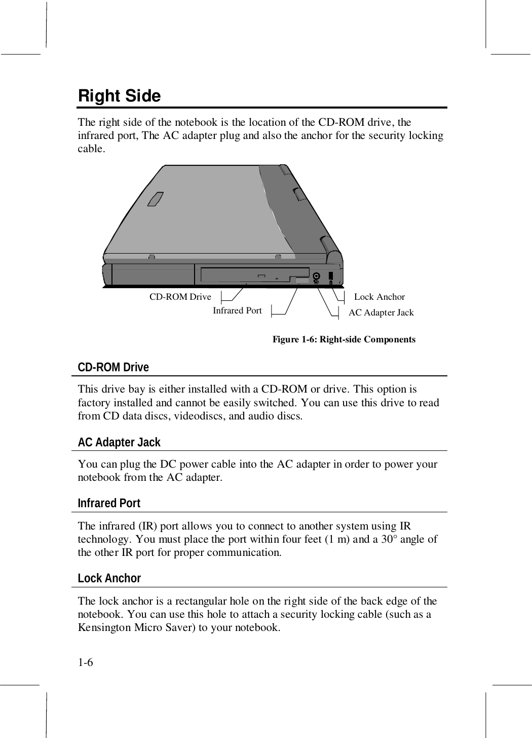
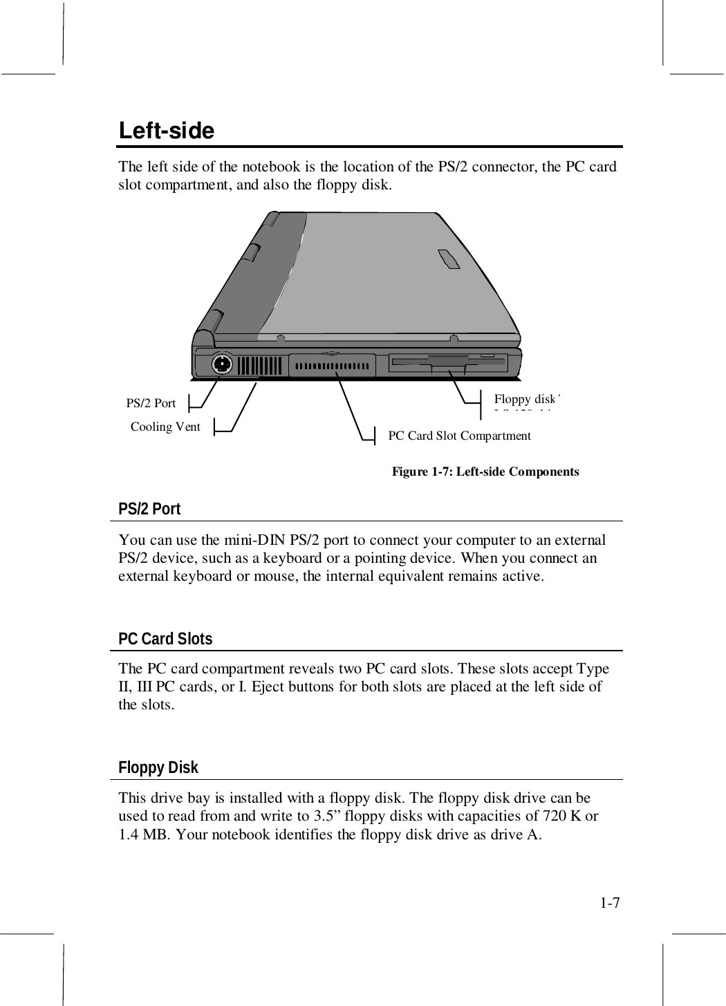
MANUAL CHAP 1
3.
MANUAL CHAP 2
4.
MANUAL CHAP 3
5.
USER MANUAL CHAP 4
6.
USER MANUAL CHAP 5
7.
USER MANUAL CHAP 7
8.
USER MANUAL CHAP 8
9.
USER MANUAL CHAP 6
MANUAL CHAP 1
Navigation menu
Upload a User Manual
Namespaces
Wiki Guide
HTML
PDF
Info
Views
User Manual
Discussion / Help
Navigation