Delta Electronics orporated DN-715 NoteBook User Manual MANUAL CHAP 1
Delta Electronics Incorporated NoteBook MANUAL CHAP 1
Contents
MANUAL CHAP 1

C
Ch
ha
ap
pt
te
er
r
1
1
Getting Started
This chapter provides a
brief description of all
the major components
of your notebook

1-1
Introduction
Congratulations on your purchase of this powerful notebook computer. This
high-end system runs a powerful Intel Pentium III processor that is designed to
deliver smooth multimedia and lighting-fast performance.
This chapter will introduce the steps you should follow to get the notebook up
and running as quickly as possible.
Unpacking the Notebook
Your notebook comes securely packaged in a sturdy cardboard shipping
carton. Upon receiving your notebook, open the carton and carefully remove
the contents. In addition to this User’s Manual, the shipping carton should
contain the following items:
! Notebook Computer
! AC adapter and AC power cord
! Li-ion Battery Pack
! User’s Manual
! Utility CD
Carefully inspect each component to make sure nothing is missing or
damaged. If any of these items is missing or damaged, notify your dealer
immediately. Be sure to save the shipping materials and carton in case you
need to ship or store the notebook in the future.
A Quick Tour of the Notebook
Before you continue, please take a moment to become familiar with the
locating and purpose of controls, the status panel and indicators, and
connectors and ports, which are illustrated in the figures below.
1-2
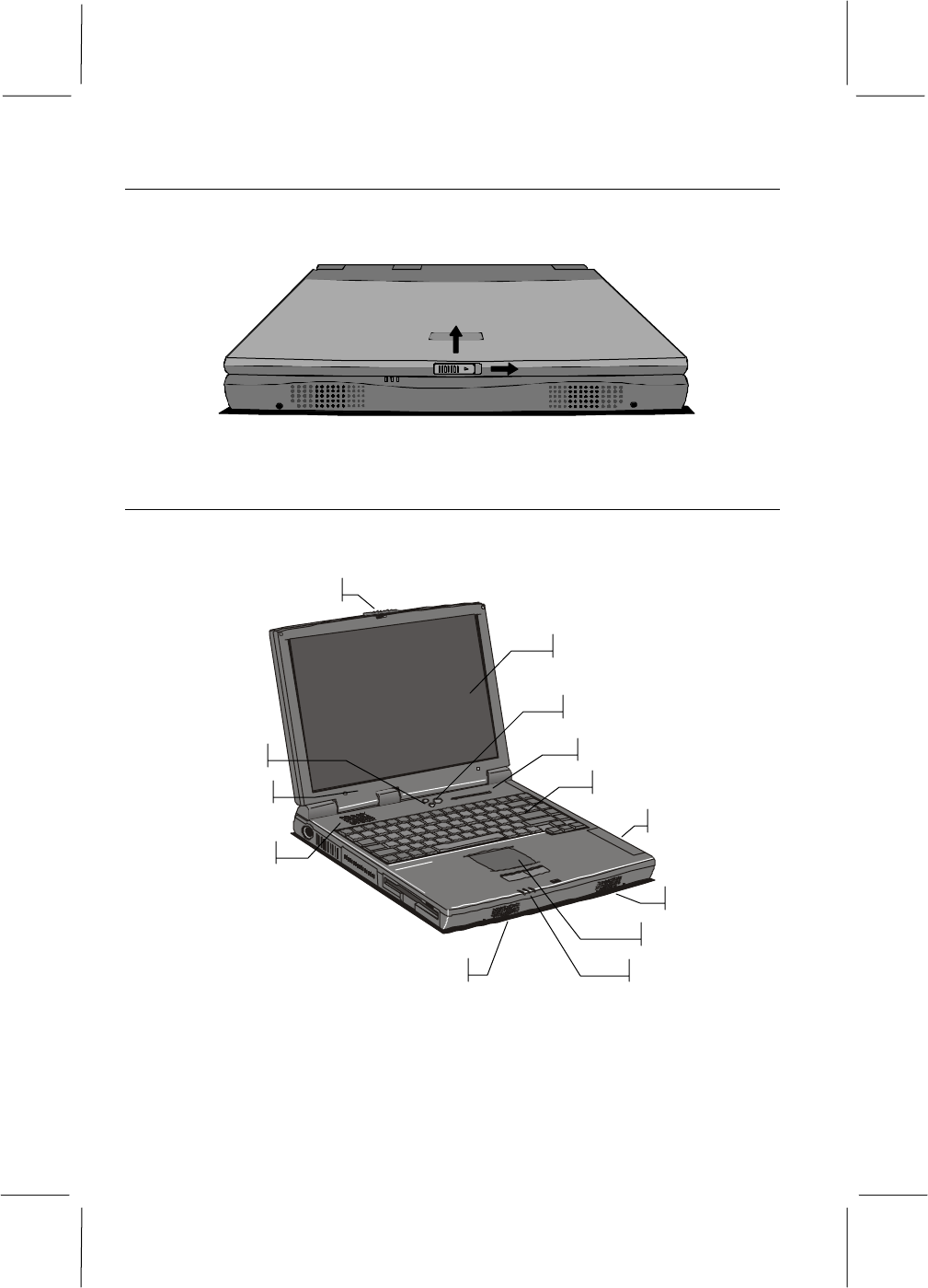
Opening the notebook
You can find a latch at the front edge of the notebook. To open the screen
cover, slide the latch toward the right to and then lift the cover.
Figure 1-1: Opening the Cover
Around the Front of the System
When the screen cover is opened, the main working area of the notebook is
visible.
Built-in Screen
Status Indicators
Power Switch
Volume Buttons
Keyboard
Battery
Power Indicators
Screen Latch
Cooling Ven
t
Touchpad
Speaker
Speaker
Microphone
Figure 1-2: Working Area
1-3
Built-in Screen
This notebook is installed with color LCD (Liquid Crystal Displays). The LCD
measures 14.1” diagonally. Screen use a TFT active matrix display that
delivers a bright, high-contrast picture. The screen resolutions are XGA (1024
x 768). XGA resolution puts the maximum information on the display, without
making the text and icons too small to be legible.
Power Switch
The power switch is located just above the keyboard in the middle, and is used
to turn the notebook on and off. Press the switch down and hold it down until
the indicator LEDs flash. Hold the switch down again for over 4 seconds to
turn the system off.
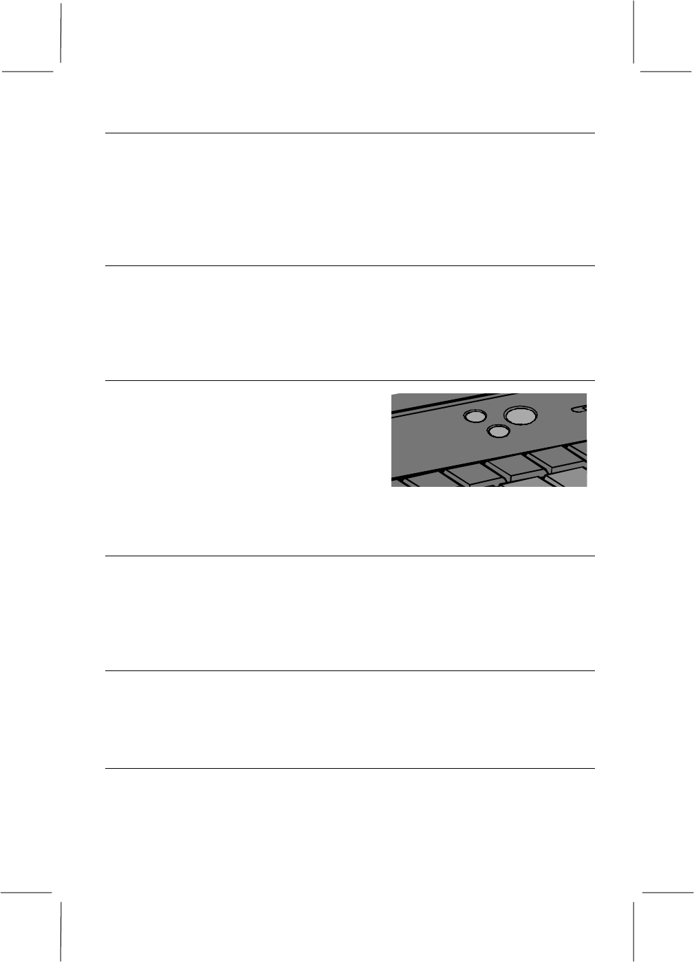
Volume Buttons
The volume buttons are located just above
the keyboard, next to the power switch.
Pressing the top button increases the
volume of the internal sound system,
pressing the lower button decreases the
volume level.
Cover-close / Suspend-resume Micro Switch
The cover-close micro switch is pressed whenever the screen cover has been
closed. When this happens, the system will either turn off the built-in screen or
suspend the system, the response is defined by the system setup utility (See
chapter 4 for information on the cover close response.)
Microphone and Speakers
Your notebook has a built-in stereo audio system. The speakers are located in
the front side of the notebook. The microphone is located below the LCD in
the cover of the notebook.
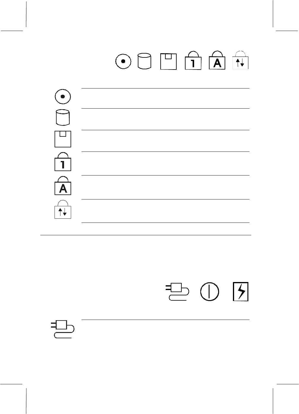
Status Indicators
The status indicators are located above the keyboard. When the system is
turned on, the indicator LEDs show the status of the system and the major
components.
Figure 1-3: Volume buttons
1-4
Figure 1-4: Status Indicators
The green LED next to this icon turns on when the notebook is
reading from a disc in the CD-ROM drive.
The green LED next to this icon turns on when the notebook is
reading from or writing to the built-in hard disk drive.
The green LED next to this icon turns on when the notebook is
reading from or writing to a diskette in the floppy disk drive.
The green LED next to this icon turns on when the keyboard is in
Num Lock mode.
The green LED next to this icon turns on when the keyboard is in
Caps Lock mode.
The green LED next to this icon turns on when the keyboard is in
Scroll Lock mode.
Power Indicators
The power indicators are located on the front edge of the notebook, below the
buttons of the touchpad. When the system is turned on, these indicators LEDs
show the power and charging status of the system and internal battery. The
power indicator LEDs are visible at all time, even when the notebook cover is
closed.
Figure 1-5: Power Indicators
The green LED next to this icon turns on when the notebook is
using power from the AC adapter.

1-5
The green LED next to this icon turns on when the notebook is
powered on. When the system is suspended to RAM, the LED
flashes. When the system is suspended to disk, or when the
system is powered down, the LED turns off.
The LED next to this icon turns on green when the battery inside
the notebook is fully charged. When the battery is charging the
LED turns amber. When there is less than 3 minutes of battery
capacity left, the LED turns red and flashes, while an audible
warning beep sounds.
Keyboard
Most versions of the built-in keyboard use 86 keys. Some non-English
keyboards may have one or two extra keys. Some keys are embedded with
several keystrokes so that the keyboard can duplicate all the keystrokes of a
standard desktop AT or PS/2 keyboard with 101/102 keys. The keyboard is
optimized for Windows and has two kinds of special Windows keys. On top of
these standard desktop keyboard functions, the notebook keyboard also has hot
keys to give the user direct access to a series of often-used functions (See
chapter 2 for more information on the keyboard.)
Touchpad
The touchpad is your notebook’s pointing device. In a graphical environment
like Windows, the touchpad surface acts like a representation of the built-in
screen. When you move your fingertip over the touchpad surface, the pointer
on the screen moves in the same direction. (See chapter 2 for more information
on the touchpad.)
1-6
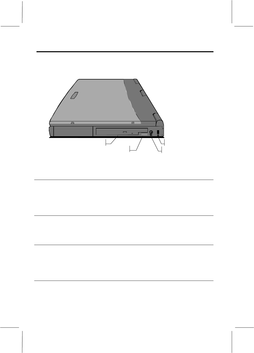
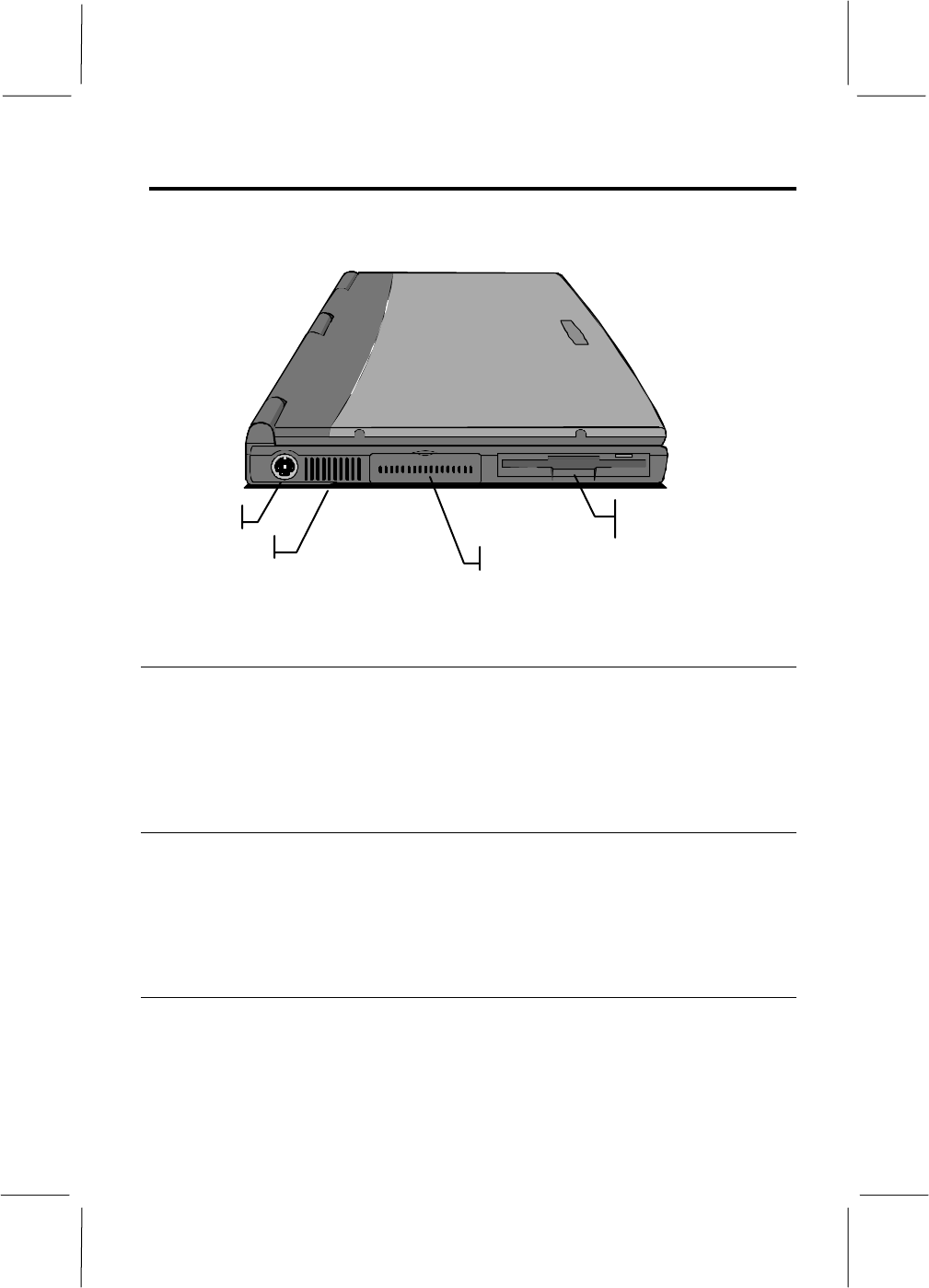
Right Side
The right side of the notebook is the location of the CD-ROM drive, the
infrared port, The AC adapter plug and also the anchor for the security locking
cable.
Lock Anchor CD-ROM Drive
AC Adapter Jack
Infrared Port
Figure 1-6: Right-side Components
CD-ROM Drive
This drive bay is either installed with a CD-ROM or drive. This option is
factory installed and cannot be easily switched. You can use this drive to read
from CD data discs, videodiscs, and audio discs.
AC Adapter Jack
You can plug the DC power cable into the AC adapter in order to power your
notebook from the AC adapter.
Infrared Port
The infrared (IR) port allows you to connect to another system using IR
technology. You must place the port within four feet (1 m) and a 30° angle of
the other IR port for proper communication.
Lock Anchor
The lock anchor is a rectangular hole on the right side of the back edge of the
notebook. You can use this hole to attach a security locking cable (such as a
Kensington Micro Saver) to your notebook.
1-7
Left-side
The left side of the notebook is the location of the PS/2 connector, the PC card
slot compartment, and also the floppy disk.
Floppy disk/
LS-120 drive
PS/2 Por
t
PC Card Slot Compartment
Cooling Vent
Figure 1-7: Left-side Components
PS/2 Port
You can use the mini-DIN PS/2 port to connect your computer to an external
PS/2 device, such as a keyboard or a pointing device. When you connect an
external keyboard or mouse, the internal equivalent remains active.
PC Card Slots
The PC card compartment reveals two PC card slots. These slots accept Type
II, III PC cards, or I. Eject buttons for both slots are placed at the left side of
the slots.
Floppy Disk
This drive bay is installed with a floppy disk. The floppy disk drive can be
used to read from and write to 3.5” floppy disks with capacities of 720 K or
1.4 MB. Your notebook identifies the floppy disk drive as drive A.
1-8
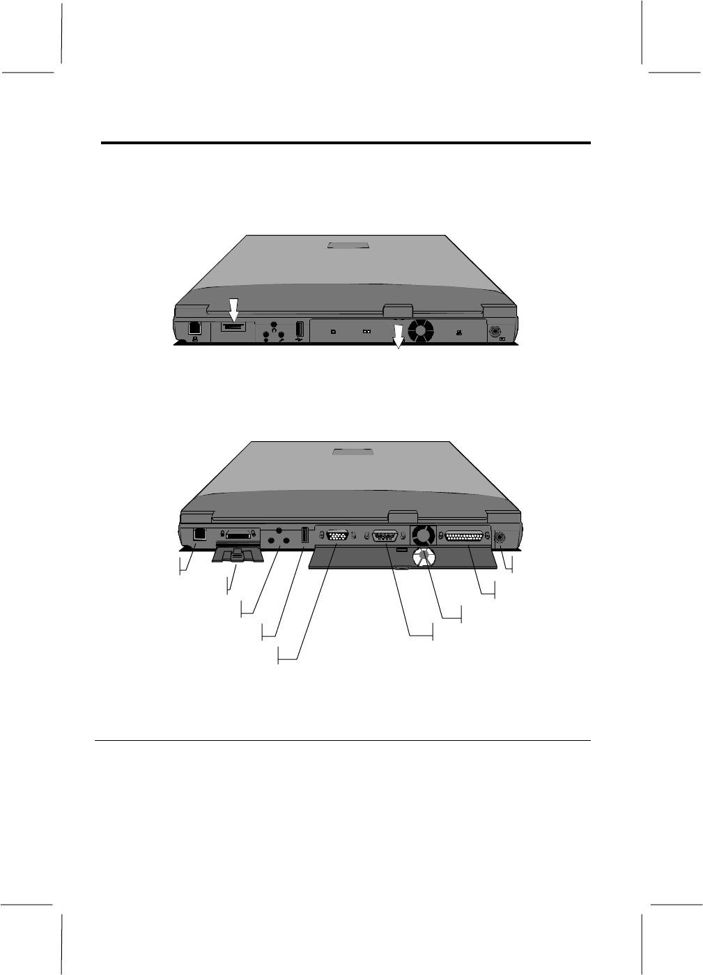
Rear Side
The rear side of the notebook has a series of connectors. Some of these
connectors are located inside a separate compartment. Each compartment has a
pull-down door to protect the ports inside the compartments. The illustration
and list below identifies the function of each of the connectors.
Figure 1-8: Connector Compartments
To access the covered compartments, pull down the doors. The door of the
expansion connector compartment flaps away underneath the notebook.
TV-out Port
Fax/Modem
Expansion Connector
Audio Jacks
USB Port
Monitor Port
Parallel Port
Serial Port
Cooling Vent
Figure 1-9: Rear-side connectors
Fax/Modem
The fax/modem line-in jack provides the connection for the internal
fax/modem device. If your notebook did not come with this factory-installed
option, the access to this jack will be blocked with a cap. The jack does not
provide a pass-through option for connecting a phone to this same line, but
you can obtain optional adapters that allow you to do this.
1-9
Expansion Connector
The expansion connector is used for connecting your notebook to proprietary
optional expansion modules, such as a port replicator.
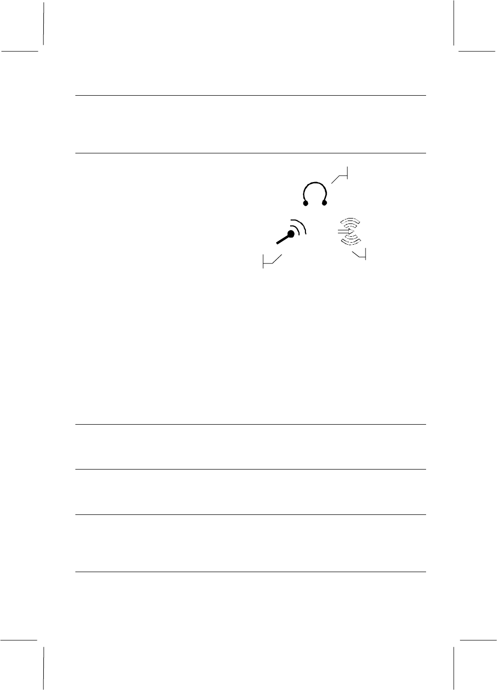
Audio Jacks
Audio Input Jack
You can use this
jack to input stereo
sound from other
devices, such as a
radio or tape
recorder, into your
notebook.
External Microphone Jack
You can use this jack to input sound from an external microphone into your
notebook. When an external microphone is connected to this jack, the built-in
microphone is automatically disabled.
Audio Output Jack
You can use this jack to output sound generated by your notebook to an
external device, such as stereo loudspeakers or headphones. When an external
device is connected, the built-in speakers are automatically disabled.
USB Port
The USB (Universal Serial Bus) port can be used to connect to USB devices.
Monitor Port
The monitor port can be used to connect to an external monitor.
Serial Port
The serial port COM1 can be used to connect to serial devices such as a mouse
or a fax/modem.
Parallel Port
The parallel port LPT1 can be used to connect to parallel devices such as a
printer.
Audio Input
Audio Output
External Microphone
Figure 1-10: Audio Jacks
1-10
TV-out Port
The RCA video jack can be used to output video to devices that use RCA
plugs such as most TV receivers.
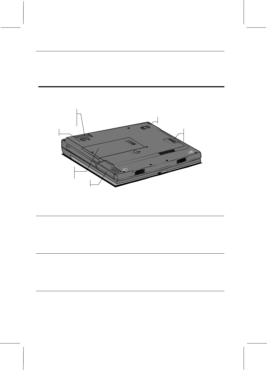
Around the Bottom of the System
If you close the screen cover and turn the unit over, you can locate the
components installed on the base of the unit.
BIOS CMOS
Compartment
Foot
Foot
Battery
Memory
Compartment
Expansion
Compartment
Door Hideaway
Figure 1-1: Base Components
Battery
The notebook contains a removable, rechargeable Lithium ion (Li-Ion) battery
pack that provides power when you are away from an AC outlet. You can
recharge it many times.
Ergonomic Feet
There are two feet located at the back of the base of the notebook. Opening
these feet allows the notebook to slightly tilt forward towards you, to make the
keyboard more easily accessible.
BIOS CMOS Compartment
This compartment gives access to the BIOS chip that holds the System
Configuration Utility information. We recommend not to open the
compartment, and never to remove the chip from the notebook.

1-11
Hard Disk Drive and System Memory
It can’t identify these two items by exploring your notebook because they are
internal items installed inside the system case. However, they are very
important components, which store the software and data that your computer
uses.
Hard Disk Drive
The notebook is installed with a hard disk drive, which can store from 3 to 6 or
more gigabytes (GB) of software and data. Over time, new hard disk drives
with higher capacities will appear, so if you feel that you need more hard disk
space, you can ask your vendor about upgrades. The hard disk drive provides
long-term storage, because the software and data is held intact even when the
computer is turned off. That’s why, before you turn off your computer, you
must always make sure that the data or files held in the system memory, are
securely saved to disk.
System Memory
The notebook is usually installed with 32 megabytes (MB) of system memory.
This is plenty of memory for most kind of computer applications. However, if
you feel that you need more memory, you can ask your system vendor to
upgrade the memory. System memory stores applications and data while the
system is turned on. When the system is turned off, all the data stored in
system memory is lost.