E F Johnson 2425110 242-5110 User Manual CERTIFICATE OF COMPLIANCE
E. F. Johnson Company 242-5110 CERTIFICATE OF COMPLIANCE
Contents
Manual

Rhein Tech Laboratories E. F. Johnson Co.
360 Herndon Parkway
Suite 1400
Model: 242-5110 / 242-5111
FCC Part 90 & IC RSS-119
Herndon, VA 20170 Permissive Change
http://www.rheintech.com RTL WO# 2002213
10 of 17
APPENDIX C: USER MANUAL
Please refer to the following pages, specifically pages 8 and 9, that include the new, optional antenna.
DIGITAL/ANALOG PORTABLE RADIO
SERVICE
MANUAL
Part Number: 001-5100-0012CD
November 2002
Supersedes: 001-5100-0011CD; 6/02
5100 SERIES
PORTABLE RADIO
VHF
PROJECT 25 CONVENTIONAL
SMARTNET®
/SMARTZONE®
7.2 VDC,
1 and 5 Watts (VHF);
Part No. 242-51xx-xxx

51xx SERIES PORTABLE
VHF
PROJECT 25 (DIGITAL) AND ANALOG
SMARTNET®/SmartZone®
7.5 VDC
5 & 1 W (VHF)
Part No. 242-51xx-xx0
Copyright© 2002 by the E.F. Johnson Company
The E.F. Johnson Company, which was founded in 1923, provides wireless communication
systems solutions for public safety, government, and commercial customers. The company
designs, manufactures, and markets conventional and trunked radio systems, mobile and
portable subscriber radios, repeaters, and Project 25 digital radio products. E.F. Johnson is a
wholly owned subsidiary of EFJ, Inc., formerly Transcrypt International, Inc.
Viking Head/EFJohnson logo, Call Guard®, PCConfigure™, and PCTune™ are trademarks of
the E.F. Johnson Company. SMARTNET®, SmartZone®, SecureNet™, Call Alert™, and
Enhanced Private Conversation™ are trademarks of Motorola, Inc. All other company and/or
product names used in this manual are trademarks and/or registered trademarks of their
respective manufacturer. The IMBE™ voice coding technology embodied in this product is
protected by intellectual property rights including patent rights of Digital Voice Systems, Inc.
Information in this manual is subject to change without notice.

TABLE OF CONTENTS
ii Revised November 2002
TABLE OF CONTENTS
1 GENERAL INFORMATION
1.1 SCOPE OF MANUAL . . . . . . . . . . . . . . . . . . . 1-1
1.2 TRANSCEIVER DESCRIPTION . . . . . . . . . . 1-1
General. . . . . . . . . . . . . . . . . . . . . . . . . . . . . . . . . 1-1
Analog/Digital Operation . . . . . . . . . . . . . . . . . . 1-1
Operating Protocols . . . . . . . . . . . . . . . . . . . . . . . 1-1
Full and Limited Keypad Models . . . . . . . . . . . . 1-1
Systems, Channels, and Zones. . . . . . . . . . . . . . . 1-2
Secure Communication . . . . . . . . . . . . . . . . . . . . 1-2
Programming . . . . . . . . . . . . . . . . . . . . . . . . . . . . 1-2
Alignment . . . . . . . . . . . . . . . . . . . . . . . . . . . . . . 1-2
1.3 PRODUCT WARRANTY . . . . . . . . . . . . . . . . . 1-3
1.4 PART NUMBER BREAKDOWN . . . . . . . . . . 1-3
1.5 TRANSCEIVER IDENTIFICATION . . . . . . . . 1-3
1.6 ACCESSORIES . . . . . . . . . . . . . . . . . . . . . . . . 1-3
1.7 FACTORY CUSTOMER SERVICE . . . . . . . . 1-4
1.8 FACTORY RETURNS . . . . . . . . . . . . . . . . . . . 1-5
1.9 REPLACEMENT PARTS . . . . . . . . . . . . . . . . 1-5
1.10 INTERNET HOME PAGE . . . . . . . . . . . . . . . . 1-5
2 BATTERY, ACCESSORY, AND
DISASSEMBLY INFORMATION
2.1 BATTERY INFORMATION . . . . . . . . . . . . . . . 2-1
Battery Removal/Installation. . . . . . . . . . . . . . . . 2-1
Battery Care. . . . . . . . . . . . . . . . . . . . . . . . . . . . . 2-1
2.2 BELT CLIP INSTALLATION . . . . . . . . . . . . . 2-2
2.3 ACCESSORY INSTALLATION . . . . . . . . . . . 2-2
2.4 TRANSCEIVER DISASSEMBLY. . . . . . . . . . 2-3
Separating Front Cover and Chassis . . . . . . . . . . 2-3
Removing RF and Logic Boards From Chassis . 2-4
Removing UI (User Interface) Board . . . . . . . . . 2-5
Removing Switch assembly. . . . . . . . . . . . . . . . . 2-6
3 OPERATION
3.1 GENERAL . . . . . . . . . . . . . . . . . . . . . . . . . . . . . 3-1
4 TRANSCEIVER PROGRAMMING
4.1 PROGRAMMING SETUP . . . . . . . . . . . . . . . . 4-1
4.2 COMPUTER DESCRIPTION . . . . . . . . . . . . . 4-1
4.3 USING THE PCCONFIGURE SOFTWARE. 4-1
4.4 CLONING PROCEDURE . . . . . . . . . . . . . . . . 4-2
5 CIRCUIT DESCRIPTION
5.1 GENERAL OVERVIEW . . . . . . . . . . . . . . . . . . 5-1
Introduction . . . . . . . . . . . . . . . . . . . . . . . . . . . . 5-1
Analog Mode . . . . . . . . . . . . . . . . . . . . . . . . . . . 5-1
Project 25 Digital Mode. . . . . . . . . . . . . . . . . . . 5-2
RF Board OVERVIEW . . . . . . . . . . . . . . . . . . . 5-2
5.2 VHF/UHF RF BOARD . . . . . . . . . . . . . . . . . . . 5-3
Frequency Generation Unit (FGU) . . . . . . . . . . 5-3
Antenna Switch . . . . . . . . . . . . . . . . . . . . . . . . . 5-4
Receiver Front End . . . . . . . . . . . . . . . . . . . . . . 5-5
Receiver Back End. . . . . . . . . . . . . . . . . . . . . . . 5-5
Transmitter. . . . . . . . . . . . . . . . . . . . . . . . . . . . . 5-6
5.3 800 MHz RF BOARD . . . . . . . . . . . . . . . . . . . . 5-6
Frequency Synthesis . . . . . . . . . . . . . . . . . . . . . 5-6
Antenna Switch . . . . . . . . . . . . . . . . . . . . . . . . . 5-8
Receiver Front End . . . . . . . . . . . . . . . . . . . . . . 5-8
Receiver Back End. . . . . . . . . . . . . . . . . . . . . . . 5-9
Transmitter. . . . . . . . . . . . . . . . . . . . . . . . . . . . . 5-9
5.4 USER INTERFACE (UI) BOARD . . . . . . . . . 5-10
Introduction . . . . . . . . . . . . . . . . . . . . . . . . . . . 5-10
Microcontroller (U2) . . . . . . . . . . . . . . . . . . . . 5-10
Memory . . . . . . . . . . . . . . . . . . . . . . . . . . . . . . 5-10
Graphical Display . . . . . . . . . . . . . . . . . . . . . . 5-10
5.5 LOGIC BOARD . . . . . . . . . . . . . . . . . . . . . . . . 5-10
Introduction . . . . . . . . . . . . . . . . . . . . . . . . . . . 5-10
Digital Signal Processing Overview . . . . . . . . 5-10
Receive Signal Path . . . . . . . . . . . . . . . . . . . . . 5-11
Transmit Signal Path . . . . . . . . . . . . . . . . . . . . 5-12
ADSIC (U2) . . . . . . . . . . . . . . . . . . . . . . . . . . . 5-12
5.6 AUDIO CIRCUIT . . . . . . . . . . . . . . . . . . . . . . . 5-12
Receive Audio Circuit . . . . . . . . . . . . . . . . . . . 5-12
Transmit Audio Circuit . . . . . . . . . . . . . . . . . . 5-13
6 ALIGNMENT PROCEDURE
6.1 GENERAL . . . . . . . . . . . . . . . . . . . . . . . . . . . . . 6-1
Introduction . . . . . . . . . . . . . . . . . . . . . . . . . . . . 6-1
Tune Software . . . . . . . . . . . . . . . . . . . . . . . . . . 6-1
6.2 MAIN SCREEN . . . . . . . . . . . . . . . . . . . . . . . . . 6-2
General. . . . . . . . . . . . . . . . . . . . . . . . . . . . . . . . 6-2
6.3 MENU BAR DESCRIPTION . . . . . . . . . . . . . . 6-3
File Menu . . . . . . . . . . . . . . . . . . . . . . . . . . . . . . 6-3
Serial Menu . . . . . . . . . . . . . . . . . . . . . . . . . . . . 6-3
Radio Menu . . . . . . . . . . . . . . . . . . . . . . . . . . . . 6-3
Help Menu . . . . . . . . . . . . . . . . . . . . . . . . . . . . . 6-4
6.4 TUNING PROCEDURE . . . . . . . . . . . . . . . . . . 6-4
Connecting Test Setup . . . . . . . . . . . . . . . . . . . . 6-4
Starting and Configuring PCTune . . . . . . . . . . . 6-4

TABLE OF CONTENTS (CONT’D)
iii Revised November 2002
TABLE OF CONTENTS
7 PARTS LIST
Chassis, Hardware, Misc . . . . . . . . . . . . . . . . . . . 7-1
RF Board (A215) . . . . . . . . . . . . . . . . . . . . . . . . . 7-1
Logic Board . . . . . . . . . . . . . . . . . . . . . . . . . . . . . 7-2
User Interface Board (A400) . . . . . . . . . . . . . . . . 7-4
Exploded Views. . . . . . . . . . . . . . . . . . . . . . . . . . 7-9
8 SCHEMATIC DIAGRAMS AND
COMPONENT LAYOUTS
Interconnect Schematic. . . . . . . . . . . . . . . . . . . 8-1
VHF RF Board
Schematic . . . . . . . . . . . . . . . . . . . . . . . . . . . . . 8-2
Board Layout. . . . . . . . . . . . . . . . . . . . . . . . . . . 8-5
UHF RF Board
Schematic . . . . . . . . . . . . . . . . . . . . . . . . . . . . . 8-6
Board Layout. . . . . . . . . . . . . . . . . . . . . . . . . . . 8-9
800 MHz RF Board
Schematic . . . . . . . . . . . . . . . . . . . . . . . . . . . . 8-10
Board Layout. . . . . . . . . . . . . . . . . . . . . . . . . . 8-13
Logic Board
Schematic . . . . . . . . . . . . . . . . . . . . . . . . . . . . 8-14
Board Layout. . . . . . . . . . . . . . . . . . . . . . . . . . 8-16
UI (User Interface) Board
Schematic . . . . . . . . . . . . . . . . . . . . . . . . . . . . 8-17
Board Layout. . . . . . . . . . . . . . . . . . . . . . . . . . 8-19
Programming Cable Schematic . . . . . . . . . . . 8-21
LIST OF FIGURES
4-1 Programming Setup . . . . . . . . . . . . . . . . . . . . . . 4-1
5-1 RF Board Block Diagram . . . . . . . . . . . . . . . . . 5-3
6-1 Alignment Setup . . . . . . . . . . . . . . . . . . . . . . . . 6-1
6-2 PCTune Main Screen . . . . . . . . . . . . . . . . . . . . . 6-2
6-3 Test Box Front Panel . . . . . . . . . . . . . . . . . . . . . 6-4
LIST OF TABLES
1-1 Accessories . . . . . . . . . . . . . . . . . . . . . . . . . . . . . 1-4
5-1 LO and First IF Frequencies . . . . . . . . . . . . . . . . 5-2

1-1 Revised July 2002
GENERAL INFORMATION
SECTION 1 GENERAL INFORMATION
1.1 SCOPE OF MANUAL
This service manual contains operation, program-
ming, alignment, and service information for the
EFJohnson 5100-Series portable digital transceivers.
1.2 TRANSCEIVER DESCRIPTION
1.2.1 GENERAL
The 5100-series portable digital transceivers have
multiple system programming capability to allow
operation in various types of radio systems as
described in the information which follows.
Models are available for operation in the
following frequency ranges. Repeater talk-around,
which allows transmitting on the receive frequency, is
also available with all bands.
VHF: 136-174 MHz
Power output is user switchable for low and high
levels as follows:
VHF - 1 and 5 watts
1.2.2 ANALOG/DIGITAL OPERATION
The 5100-series transceiver uses a digital signal
processor (DSP) to provide IF and audio filtering and
modulation functions. This allows operation on the
various types of channels (see following), backward
compatibility with existing equipment, and the ability
to operate on various types of radio systems.
Narrow Band Analog - FM modulation is used with a
maximum deviation of 2.5 kHz. This mode is usually
used in systems with a channel spacing of 12.5 or 15
kHz.
Wideband Analog - FM modulation is used with a
maximum deviation of 5 kHz. This mode is usually
used in systems where the channel spacing is 25 kHz
or 30 kHz.
Project 25 Digital - Operates on Project 25 compatible
systems. The voice is digitized, error corrected,
optionally encrypted, and then transmitted using
C4FM modulation according to the Project 25 stan-
dard. This mode uses a channel spacing of 12.5 kHz.
1.2.3 OPERATING PROTOCOLS
Standard 5100-series transceivers can be
programmed for any or all the following operating
protocols. The conventional analog protocol is stan-
dard and the others are optional and therefore are
available only if enabled by factory programming.
Refer to Section 3 for more operation information.
•Conventional analog
•Conventional Project 25 (digital)
•SMARTNET™/SmartZone® analog or digital
•Trunked Project 25 (digital)
NOTE: Some of the above protocols are not available
with early units.
Multi-Net® versions of this radio are planned for
future release. These versions will be programmable
for Multi-Net and conventional analog operation.
However, future migration to any of the other proto-
cols listed above will be possible by reflashing the
operating software. This manual does not include
Multi-Net operation information.
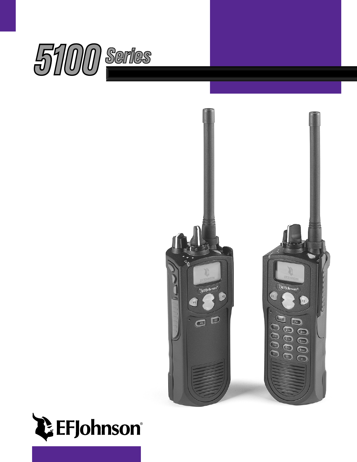
1.2.4 FULL AND LIMITED KEYPAD MODELS
Both DTMF (18-key) and limited (6-key) models
are available. The DTMF keypad version includes the
0-9, *, and # keys for making telephone calls, entering
unit or group ID numbers, and keypad programming.
Both models have programmable F1-F4 option
keys and the Up/Down switch on the front panel. In
addition, both models have a push-button and a rotary
switch on the top panel and three push-buttons on the
side panel that are programmable. A menu mode can
also be programmed with both models to select func-
tions that are selectable by the option buttons. Refer to

GENERAL INFORMATION
1-2 Revised November 2002
Section 3 for more information on transceiver
operation.
1.2.5 SYSTEMS, CHANNELS, AND ZONES
A zone and channel are selected to place and
receive calls. The following describes the relationship
between systems, channels, and zones.
Systems
A system is a collection of channels or talk
groups belonging to the same repeater site. It defines
all the parameters and protocol information required to
access a site. Up to 16 systems of any type can be
programmed. The maximum number of channels
assignable to a system is limited to approximately 256
with standard models or approximately 500 with the
512-channel option (or the available memory space as
described in the following information).
Channels
A channel selects a radio (RF) channel or talk
group as follows:
Conventional Analog Mode - A channel selects a
specific radio channel, Call Guard (CTCSS/DCS)
squelch coding, and other parameters unique to that
channel.
Conventional Project 25 Mode - A channel selects a
specific radio channel, NAC squelch coding, talk
group ID, and other parameters unique to that channel.
Trunked Project 25 Mode - A channel selects a
specific talk group ID and other parameters unique to
that talk group.
SMARTNET/SmartZone and Project 25 Trunked
Operation - A channel selects a specific talk group,
announcement group, emergency group, and other
parameters unique to that talk group.
As described in the preceding “Systems” descrip-
tion, a maximum of up to 256 or approximately 500
channels can be programmed. Although it is theoreti-
cally possible to program any combination of systems
that produces up to 500 total channels, the maximum
number is also limited by the available memory. For
example, since more memory is required to program a
SMARTNET system than a conventional system, the
total number of channels decreases as the number of
SMARTNET systems increases. The programming
software displays a bar graph which shows the amount
of available memory space that is used by the current
data. Refer to Section 4 for more information.
Zones
A zone is a collection of up to 16 channels of any
type. For example, a zone could include 12 conven-
tional channels and 4 SMARTNET channels. One use
of zones may be to program the channels used for
operation in a different geographical areas. Up to 16
zones can be programmed with standard models and
up to 32 can be programmed if the 512-channel option
is enabled.
1.2.6 SECURE COMMUNICATION
SecureNet™ voice encryption is used to provide
secure communication with this transceiver. SecureNet
is a proprietary Motorola protocol that digitizes the
voice and then encrypts it using a DES algorithm. The
following types of SecureNet encryption are available:
Analog Conventional and SMARTNET/SmartZone
Channels
•DES (DES-XL is not available)
Digital SMARTNET/SmartZone and Project 25
Channels
•DES-OFB (Output Feedback)
1.2.7 PROGRAMMING
Transceiver programming is performed using a
PC-compatible computer, the EFJohnson 5100
Programming Cable, and PCConfigure programming
software (see Table 1-1). Programming is described in
Section 4.
1.2.8 ALIGNMENT
Transceiver alignment is performed using
EFJohnson PCTune software and 5100 test box, and
the same computer used for programming (see
preceding section). All adjustments are made electron-

GENERAL INFORMATION
1-3 Revised November 2002
ically using the software (no manual adjustments are
required). Refer to Section 6 for alignment
information.
1.3 PRODUCT WARRANTY
The warranty statement for this transceiver is
available from your product supplier or from the
Warranty Department, E.F. Johnson Company, 299
Johnson Avenue, P.O. Box 1249, Waseca, MN 56093-
0514. This information may also be requested from the
Warranty Department by phone as described in
Section 1.7. The Warranty Department may also be
contacted for Warranty Service Reports, claim forms,
or any other questions concerning warranties or
warranty service.
1.4 PART NUMBER BREAKDOWN
The following is a breakdown of the part number
used to identify this transceiver. Some combinations
are not available.
F (Frequency Band)
1 - VHF (136-174 MHz)
3 - UHF (403-470 MHz)
4 - UHF (450-512 MHz)
8 - 800 MHz
9 - 900 MHz
K (Keypad)*
2 - Standard, Limited keypad
3 - Standard, DTMF keypad
6 - Intrin Safe, Limited keypad
7 - Intrin Safe, DTMF keypad
A (Antenna)
0 - No antenna
1 - VHF 136-151 MHz
2 - VHF 151-162 MHz
3 - VHF 162-174 MHz
4 - UHF 403-520 MHz
8 - 800 MHz
B (Battery)
0 - No battery
1 - Ultra high capacity, NiMH
6 - Intrin Safe, ultra high cap NiMH
C (Reserved for future use)
D Primary Operating Protocol
A - Analog Conventional
B - P25 Conventional
C - P25 Trunking
D - SMARTNET Analog
E - SMARTNET Digital
F - SmartZone Analog
G - SmartZone Digital
H - STAR Trunking Analog
J - STAR Trunking Digital
K - Multi-Net Analog
NOTE: The above “D” character indicates only the
primary protocol. Other protocols (and options) may
also be included and are indicated by the next “E”
letter.
E Options
This letter indicates other operating protocols and
options that are enabled by factory programming.
Options may include encryption, OTAR, 512 Talk
Groups, Digital SMARTNET/SmartZone, and others.
Some combinations are currently be undefined, so use
the Transfer > Read Options From Radio menu
function of PCConfigure to determine which protocols
and options are enabled in your radio (see Section 4).
1.5 TRANSCEIVER IDENTIFICATION
The transceiver identification number is printed
on a label that is attached to the chassis. The following
information is contained in the identification number:
1.6 ACCESSORIES
The accessories available for this transceiver are
listed in Table 1-1.
242-51FK-ABC-Dx
51xx 0 A 12 2 A 12345
Model Revision
Letter
Manufacture
Date
Warranty
Number
Week No.
of Year Last Digit of Year
A = Waseca
PlantFrom P.N.

GENERAL INFORMATION
1-4 Revised November 2002
1.7 FACTORY CUSTOMER SERVICE
The Customer Service Department of the E.F.
Johnson Company provides customer assistance on
technical problems and the availability of local and
factory repair facilities. Regular Customer Service
hours are 7:30 a.m. - 5:30 p.m. Central Time, Monday-
Friday. A technical support subscription service is
available or support can be purchased on an as-needed
basis. The Customer Service Department can be
reached using the following telephone numbers:
Toll-Free: (800) 328-3911
FAX: (507) 835-6969
E-Mail: customerservice@efjohnson.com You can
also e-mail a person directly if you know their first
initial/last name (example: jsmith@efjohnson.com).
NOTE: Emergency 24-hour technical support is also
available at the 800 and preceding numbers during off
hours, holidays, and weekends.
Table 1-1 Accessories
Accessory Part No.
Batteries
2200 mAH NiCd 587-5100-220
3600 mAH NiMH standard 587-5100-360
Battery Chargers
Single-unit rapid chgr, w/o power supply 585-5100-210
Single-unit rapid chgr/cond w/o pwr sup 585-5100-215
Pwr supply, switching 120/230 VAC 1.3A 585-5100-230
Docking station, 4-unit for -210 ( -250
power supply included)
585-5100-240
Wall mount kit for docking station 585-5100-245
Power supply, switching 120/230 VAC
4.5A for docking station
585-5100-250
Charger kit, -210 chgr, -230 PS, US cord 250-5100-210
Charger kit, -215 chgr, -230 PS, US cord 250-5100-215
Charger kit, -210 chgr, -230 PS, Eur cord 250-5100-220
Charger kit, -215 chgr, -230 PS, Eur cord 250-5100-225
Antennas
136-151 MHz helical (yellow core) 501-0017-101
151-166 MHz helical (black core) 501-0017-103
166-174 MHz helical (blue core) 501-0017-105
136-174 MHz wideband 501-0017-108
Carrying Accessories
Belt clip, 2-1/2” std spring loaded 585-5100-128
Speaker/Microphones and Earphones
Spkr/mic, coil cord w/2.5mm earphone jk 589-0015-057
Replacement coil cord for above spkr/mic 597-2002-101
Earphone kit, coil cord w/2.5mm rt angle
plug, for -057 spkr/mic
589-5100-057
Earphone kit, coil cord w/2.5mm straight
plug, for -057 spkr/mic
589-5100-059
Earphone adapter, w/3.5 mm thrd jack 589-5100-051
Lightwght headset w/inline PTT for -051 589-0015-059
1-wire earphone kit, for -051 adapter 589-5100-053
2-wire palm mic kit, for -051 adapter 589-5100-055
Programming Accessories
5100 Programming Kit (-488 software,
-920 cable, CD manual)
250-5100-003
5100 Programming Cable 023-5100-920
5100 Cloning Cable 023-5100-930
PCConfigure programming software, CD 023-9998-488
Adapter, DB9M-DB25F 515-9000-015
Test Cables and Accessories
PCTune radio tuning software 023-9998-499
Radio test and Ethernet box 023-5100-900
Cable, -900 test box to radio 023-5100-910
DB9 M-F cable, 6 ft. (-900 to cmptr) 597-5900-002
DB25M-DB9F cable, 6 ft (-900 to cmptr) 597-0005-057
SMA F to BNC F adapter 515-3102-050
SMA M to BNC F adapter 515-3102-060
DES Encryption Keyloader
DES Key Variable Loader (KVL) 585-5000-930
Key loader to radio cable 585-5000-932
Key loader charger (NLN8858) 585-5000-934
Key loader spare battery (NLN9998) 585-5000-936
Table 1-1 Accessories (Continued)
Accessory Part No.

GENERAL INFORMATION
1-5 Revised November 2002
When your call is answered at the E.F. Johnson
Company, you will hear a brief message informing
you of numbers that can be entered to reach various
departments. This number may be entered during or
after the message using a tone-type telephone. If you
have a pulse-type telephone, wait until the message is
finished and an operator will come on the line to assist
you. When you enter some numbers, another number
is requested to further categorize the type of informa-
tion you need.
You may also contact the Customer Service
Department by mail. Please include all information
that may be helpful in solving your problem. The
mailing address is as follows:
E.F. Johnson Company
Customer Service Department
299 Johnson Avenue
P.O. Box 1249
Waseca, MN 56093-0514
1.8 FACTORY RETURNS
Repair service is normally available through local
authorized E.F. Johnson Land Mobile Radio Service
Centers. If local service is not available, the equipment
can be returned to the factory for repair. However, it is
recommended that you contact the Customer Service
Department before returning equipment. A service
representative may be able to suggest a solution to the
problem making return of the equipment unnecessary.
Be sure to fill out a Factory Repair Request Form
#271 for each unit to be repaired, whether it is in or
out of warranty. These forms are available free of
charge by calling Customer Service (see Section 1.7)
or by requesting them when you send a unit in for
repair. Clearly describe the difficulty experienced in
the space provided and also note any prior physical
damage to the equipment. Include this form in the
shipping container with each unit. Your telephone
number and contact name are important as there are
times when the technicians may have specific ques-
tions that need to be answered in order to completely
identify and repair a problem.
When returning equipment for repair, it is also
recommended that you use a PO number or some other
reference number on your paperwork in case you need
to call the repair lab about your unit. These numbers
are referenced on the repair order and make it easier
and faster to locate your unit in the lab.
Return Authorization (RA) numbers are not
necessary unless you have been given one by the Field
Service Department. RA numbers are required for
exchange units or if the Field Service Department
wants to be aware of a specific problem. If you have
been given an RA number, reference this number on
the Factory Repair Request Form sent with the unit.
The repair lab will then contact the Field Service
Department when the unit arrives.
For additional information on factory service, the
Depot Service Department can be contacted at the
following E-mail address:
depotrepair@efjohnson.com
1.9 REPLACEMENT PARTS
Replacement parts can be ordered directly from
the Service Parts Department. To order parts by phone,
dial the toll-free number as described in Section 1.7.
When ordering, please supply the part number and
quantity of each part ordered. E.F. Johnson dealers
also need to give their account number. If there is
uncertainty about the part number, include the desig-
nator (C512, for example) and the model number of
the equipment the part is from.
You may also send your order by mail or FAX.
The mailing address is as follows and the FAX number
is shown in Section 1.7.
E.F. Johnson Company
Service Parts Department
299 Johnson Avenue
P.O. Box 1249
Waseca, MN 56093-0514
1.10 INTERNET HOME PAGE
The E.F. Johnson Company has a site on the
World Wide Web that can be accessed for information
on the company about such things as products,
systems, and regulations. The address is
http://www.efjohnson.com.

GENERAL INFORMATION
1-6 Revised November 2002
5100 SERIES PORTABLE SPECIFICATIONS
The following are general specifications intended for use in testing and servicing this transceiver. For current
advertised specifications, refer to the specification sheet available from your sales representative. Values are
typical and are subject to change without notice.
GENERAL
Frequency Range VHF: 136-174 MHz
Available Operating Modes Conventional analog, Project 25 conv. and trunked, SMARTNET/SmartZone
analog and digital, Multi-Net (Multi-Net available with future release)
Talk Groups 256 standard, up to 500 optional (dependent on available memory)
Transmit/Receive Separation Any frequency within the range
Channel Spacing VHF: 12.5, 25, and 30 kHz
Maximum Deviation 25 kHz analog - 5 kHz
12.5 kHz analog - 2.5 kHz
12.5 kHz analog NPSPAC - 4.0 kHz
Frequency Stability VHF - 2.0 PPM (–22 to +140° F or –30 to +60° C)
Dimensions (w/o antenna) 6.7” H x 2.52” W x 1.9” D (17.0 cm x 6.4 cm x 4.8 cm)
Weight (w/std battery) 24 oz. (675 g)
Supply Voltage 7.2 volts DC nominal
Battery Life 13 hours typical w/std 3600 mAH battery
Current Drain (maximum Standby - 350 mA
w/backlight, w/o backlight Receive (rated audio out) - 500 mA
subtract 100 mA) Low Tx Power - 1.0 A
High Tx Power - 2.0 A
RECEIVER
Sensitivity 0.25 µV (analog mode 12 dB SINAD), 0.25 µV (digital mode 5% BER)
Selectivity –75 dB
Spurious and Image Rejection –75 dB
Intermodulation –78 dB (VHF)
Maximum Frequency Spread Any spread within the range
Audio Power Output 500 mW
Audio Distortion Less than 2% at 1 kHz
TRANSMITTER
RF Power Output VHF: 5W (high), 1W (low)
Spurious and Harmonic Emissions –70 dB (VHF)
FM Hum and Noise –45 dB at 25 kHz bandwidth
Audio Modulation 16K0F3E, 8K10F1E, 11K0F3E VHF
Audio Distortion Less than 2% at 1 kHz
Maximum Frequency Spread Any spread within the band