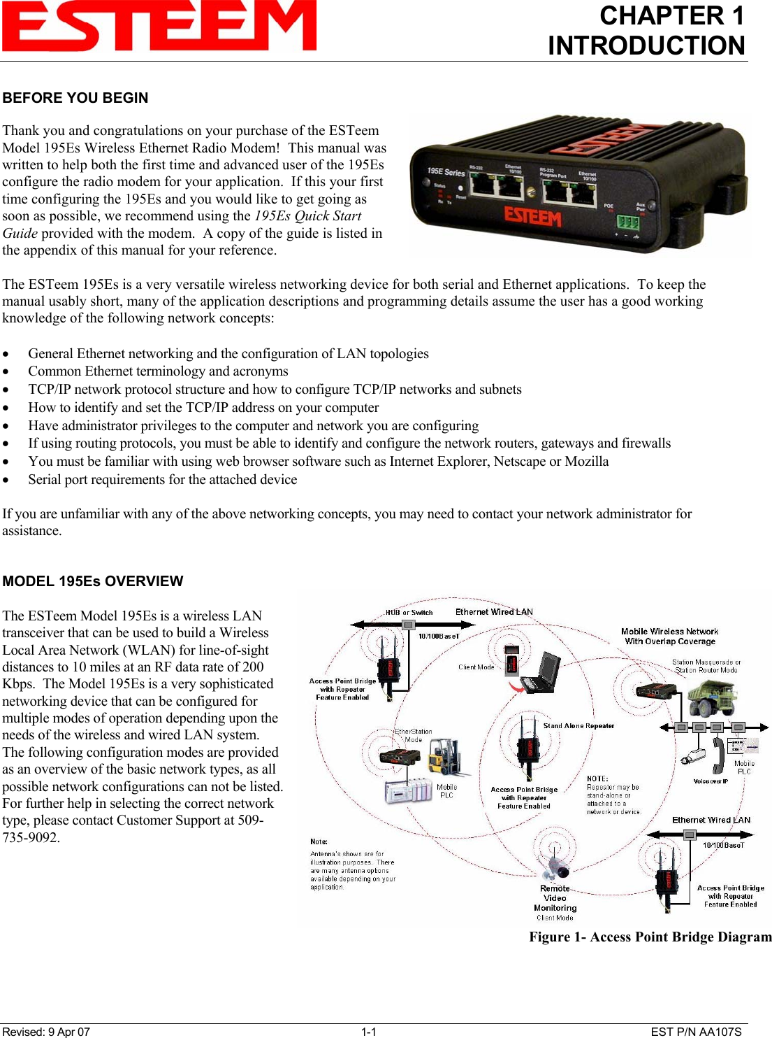
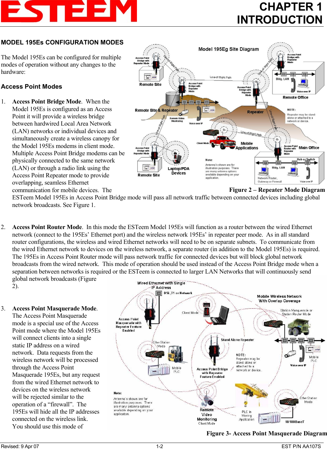
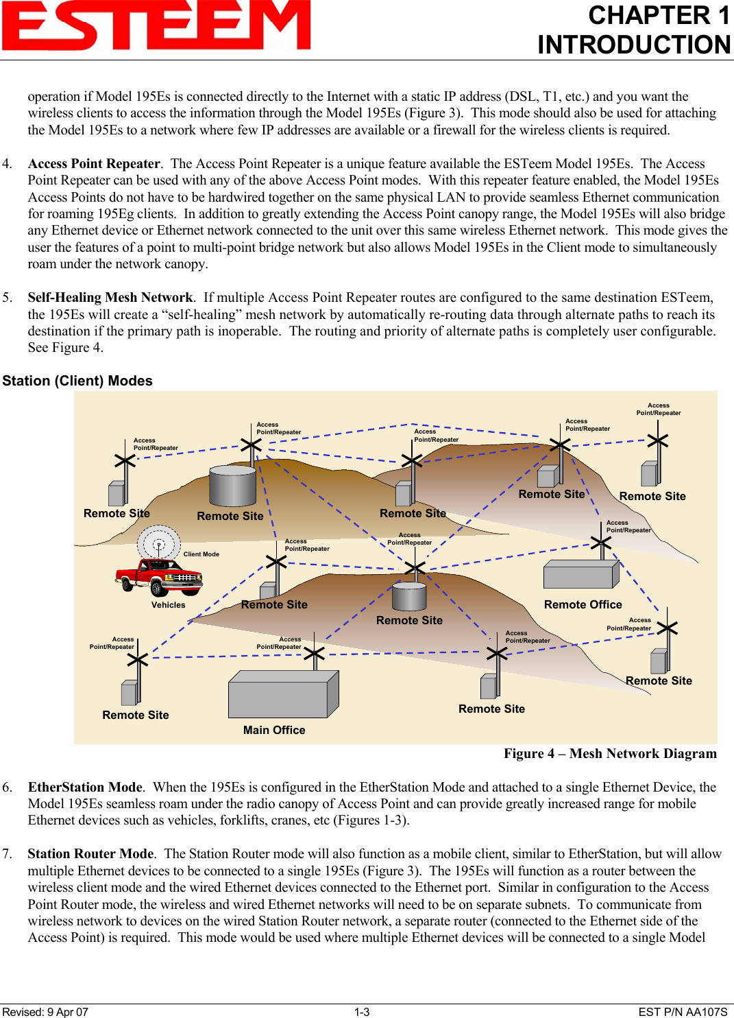
Electronic Systems Technology ESTEEM195ES Wireless Ethernet Radio Modem User Manual Chapter 1 Introduction

Electronic Systems Technology Wireless Ethernet Radio Modem Chapter 1 Introduction

Users Manual Chapter 1

CHAPTER 1INTRODUCTIONRevised: 9 Apr 07 1-1 EST P/N AA107SBEFORE YOU BEGINThank you and congratulations on your purchase of the ESTeemModel 195Es Wireless Ethernet Radio Modem!  This manual waswritten to help both the first time and advanced user of the 195Esconfigure the radio modem for your application.  If this your firsttime configuring the 195Es and you would like to get going assoon as possible, we recommend using the 195Es Quick StartGuide provided with the modem.  A copy of the guide is listed inthe appendix of this manual for your reference.The ESTeem 195Es is a very versatile wireless networking device for both serial and Ethernet applications.  To keep themanual usably short, many of the application descriptions and programming details assume the user has a good workingknowledge of the following network concepts:• General Ethernet networking and the configuration of LAN topologies• Common Ethernet terminology and acronyms• TCP/IP network protocol structure and how to configure TCP/IP networks and subnets• How to identify and set the TCP/IP address on your computer• Have administrator privileges to the computer and network you are configuring• If using routing protocols, you must be able to identify and configure the network routers, gateways and firewalls• You must be familiar with using web browser software such as Internet Explorer, Netscape or Mozilla• Serial port requirements for the attached deviceIf you are unfamiliar with any of the above networking concepts, you may need to contact your network administrator forassistance.MODEL 195Es OVERVIEWThe ESTeem Model 195Es is a wireless LANtransceiver that can be used to build a WirelessLocal Area Network (WLAN) for line-of-sightdistances to 10 miles at an RF data rate of 200Kbps.  The Model 195Es is a very sophisticatednetworking device that can be configured formultiple modes of operation depending upon theneeds of the wireless and wired LAN system. The following configuration modes are providedas an overview of the basic network types, as allpossible network configurations can not be listed.For further help in selecting the correct networktype, please contact Customer Support at 509-735-9092.Figure 1- Access Point Bridge Diagram
CHAPTER 1INTRODUCTIONRevised: 9 Apr 07 1-2 EST P/N AA107SMODEL 195Es CONFIGURATION MODESThe Model 195Es can be configured for multiplemodes of operation without any changes to thehardware:Access Point Modes1. Access Point Bridge Mode.  When theModel 195Es is configured as an AccessPoint it will provide a wireless bridgebetween hardwired Local Area Network(LAN) networks or individual devices andsimultaneously create a wireless canopy forthe Model 195Es modems in client mode. Multiple Access Point Bridge modems can bephysically connected to the same network(LAN) or through a radio link using theAccess Point Repeater mode to provideoverlapping, seamless Ethernetcommunication for mobile devices.  TheESTeem Model 195Es in Access Point Bridge mode will pass all network traffic between connected devices including globalnetwork broadcasts. See Figure 1.2. Access Point Router Mode.  In this mode the ESTeem Model 195Es will function as a router between the wired Ethernetnetwork (connect to the 195Es’ Ethernet port) and the wireless network 195Es’ in repeater peer mode.  As in all standardrouter configurations, the wireless and wired Ethernet networks will need to be on separate subnets.  To communicate fromthe wired Ethernet network to devices on the wireless network, a separate router (in addition to the Model 195Es) is required. The 195Es in Access Point Router mode will pass network traffic for connected devices but will block global networkbroadcasts from the wired network.  This mode of operation should be used instead of the Access Point Bridge mode when aseparation between networks is required or the ESTeem is connected to larger LAN Networks that will continuously sendglobal network broadcasts (Figure2).3. Access Point Masquerade Mode. The Access Point Masquerademode is a special use of the AccessPoint mode where the Model 195Eswill connect clients into a singlestatic IP address on a wirednetwork.  Data requests from thewireless network will be processedthrough the Access PointMasquerade 195Es, but any requestfrom the wired Ethernet network todevices on the wireless networkwill be rejected similar to theoperation of a “firewall”.  The195Es will hide all the IP addressesconnected on the wireless link. You should use this mode ofFigure 2 – Repeater Mode DiagramFigure 3- Access Point Masquerade Diagram
CHAPTER 1INTRODUCTIONRevised: 9 Apr 07 1-3 EST P/N AA107Soperation if Model 195Es is connected directly to the Internet with a static IP address (DSL, T1, etc.) and you want thewireless clients to access the information through the Model 195Es (Figure 3).  This mode should also be used for attachingthe Model 195Es to a network where few IP addresses are available or a firewall for the wireless clients is required.4. Access Point Repeater.  The Access Point Repeater is a unique feature available the ESTeem Model 195Es.  The AccessPoint Repeater can be used with any of the above Access Point modes.  With this repeater feature enabled, the Model 195EsAccess Points do not have to be hardwired together on the same physical LAN to provide seamless Ethernet communicationfor roaming 195Eg clients.  In addition to greatly extending the Access Point canopy range, the Model 195Es will also bridgeany Ethernet device or Ethernet network connected to the unit over this same wireless Ethernet network.  This mode gives theuser the features of a point to multi-point bridge network but also allows Model 195Es in the Client mode to simultaneouslyroam under the network canopy.5. Self-Healing Mesh Network.  If multiple Access Point Repeater routes are configured to the same destination ESTeem,the 195Es will create a “self-healing” mesh network by automatically re-routing data through alternate paths to reach itsdestination if the primary path is inoperable.  The routing and priority of alternate paths is completely user configurable.See Figure 4.Station (Client) Modes6. EtherStation Mode.  When the 195Es is configured in the EtherStation Mode and attached to a single Ethernet Device, theModel 195Es seamless roam under the radio canopy of Access Point and can provide greatly increased range for mobileEthernet devices such as vehicles, forklifts, cranes, etc (Figures 1-3).7. Station Router Mode.  The Station Router mode will also function as a mobile client, similar to EtherStation, but will allowmultiple Ethernet devices to be connected to a single 195Es (Figure 3).  The 195Es will function as a router between thewireless client mode and the wired Ethernet devices connected to the Ethernet port.  Similar in configuration to the AccessPoint Router mode, the wireless and wired Ethernet networks will need to be on separate subnets.  To communicate fromwireless network to devices on the wired Station Router network, a separate router (connected to the Ethernet side of theAccess Point) is required.  This mode would be used where multiple Ethernet devices will be connected to a single ModelMain OfficeRemote OfficeVehiclesRemote SiteRemote SiteRemote SiteAccessPoint/RepeaterAccessPoint/RepeaterRemote SiteAccessPoint/RepeaterAccessPoint/RepeaterAccessPoint/RepeaterRemote SiteAccessPoint/RepeaterRemote SiteAccessPoint/RepeaterRemote SiteAccessPoint/RepeaterRemote SiteAccessPoint/RepeaterAccessPoint/Repeater AccessPoint/RepeaterAccessPoint/RepeaterRemote SiteRemote SiteClient ModeFigure 4 – Mesh Network Diagram
CHAPTER 1INTRODUCTIONRevised: 9 Apr 07 1-4 EST P/N AA107S195Es in a mobile client application and the connected Ethernet devices will need to be accessible from the Access Point’sLAN network.8. Station Masquerade Mode.  The Station Masquerade Mode is another mode where multiple devices will be connected to asingle ESTeem in a mobile or Client application, but unlike the Station Router mode, the Station Masquerate will consolidateall connected Ethernet devices to a single IP address on the network.  The devices connected to the Station Masquerade 195Eswill be able to access information from both the wireless and wired LAN, but will be inaccessible the other way similar inapplication to a firewall.  This mode would be used where multiple Ethernet devices will be connected to a single Model195Es in a mobile application and the IP addresses for each device will be hidden from the LAN connected to the AccessPoint.  See Figure 3.To begin setup of your wireless Ethernet network you must first configure the Model 195Es for the mode desired.  Chapter 2 willshow several examples of the different modes of operation to help select the correct mode for your application.

Navigation menu