Electronic Systems Technology ESTEEM195ES Wireless Ethernet Radio Modem User Manual Chapter 1 Introduction
Electronic Systems Technology Wireless Ethernet Radio Modem Chapter 1 Introduction
Contents
Users Manual Chapter 1
CHAPTER 1
INTRODUCTION
Revised: 9 Apr 07 1-1 EST P/N AA107S
BEFORE YOU BEGIN
Thank you and congratulations on your purchase of the ESTeem
Model 195Es Wireless Ethernet Radio Modem! This manual was
written to help both the first time and advanced user of the 195Es
configure the radio modem for your application. If this your first
time configuring the 195Es and you would like to get going as
soon as possible, we recommend using the 195Es Quick Start
Guide provided with the modem. A copy of the guide is listed in
the appendix of this manual for your reference.
The ESTeem 195Es is a very versatile wireless networking device for both serial and Ethernet applications. To keep the
manual usably short, many of the application descriptions and programming details assume the user has a good working
knowledge of the following network concepts:
• General Ethernet networking and the configuration of LAN topologies
• Common Ethernet terminology and acronyms
• TCP/IP network protocol structure and how to configure TCP/IP networks and subnets
• How to identify and set the TCP/IP address on your computer
• Have administrator privileges to the computer and network you are configuring
• If using routing protocols, you must be able to identify and configure the network routers, gateways and firewalls
• You must be familiar with using web browser software such as Internet Explorer, Netscape or Mozilla
• Serial port requirements for the attached device
If you are unfamiliar with any of the above networking concepts, you may need to contact your network administrator for
assistance.
MODEL 195Es OVERVIEW
The ESTeem Model 195Es is a wireless LAN
transceiver that can be used to build a Wireless
Local Area Network (WLAN) for line-of-sight
distances to 10 miles at an RF data rate of 200
Kbps. The Model 195Es is a very sophisticated
networking device that can be configured for
multiple modes of operation depending upon the
needs of the wireless and wired LAN system.
The following configuration modes are provided
as an overview of the basic network types, as all
possible network configurations can not be listed.
For further help in selecting the correct network
type, please contact Customer Support at 509-
735-9092.
Figure 1- Access Point Bridge Diagram
CHAPTER 1
INTRODUCTION
Revised: 9 Apr 07 1-2 EST P/N AA107S
MODEL 195Es CONFIGURATION MODES
The Model 195Es can be configured for multiple
modes of operation without any changes to the
hardware:
Access Point Modes
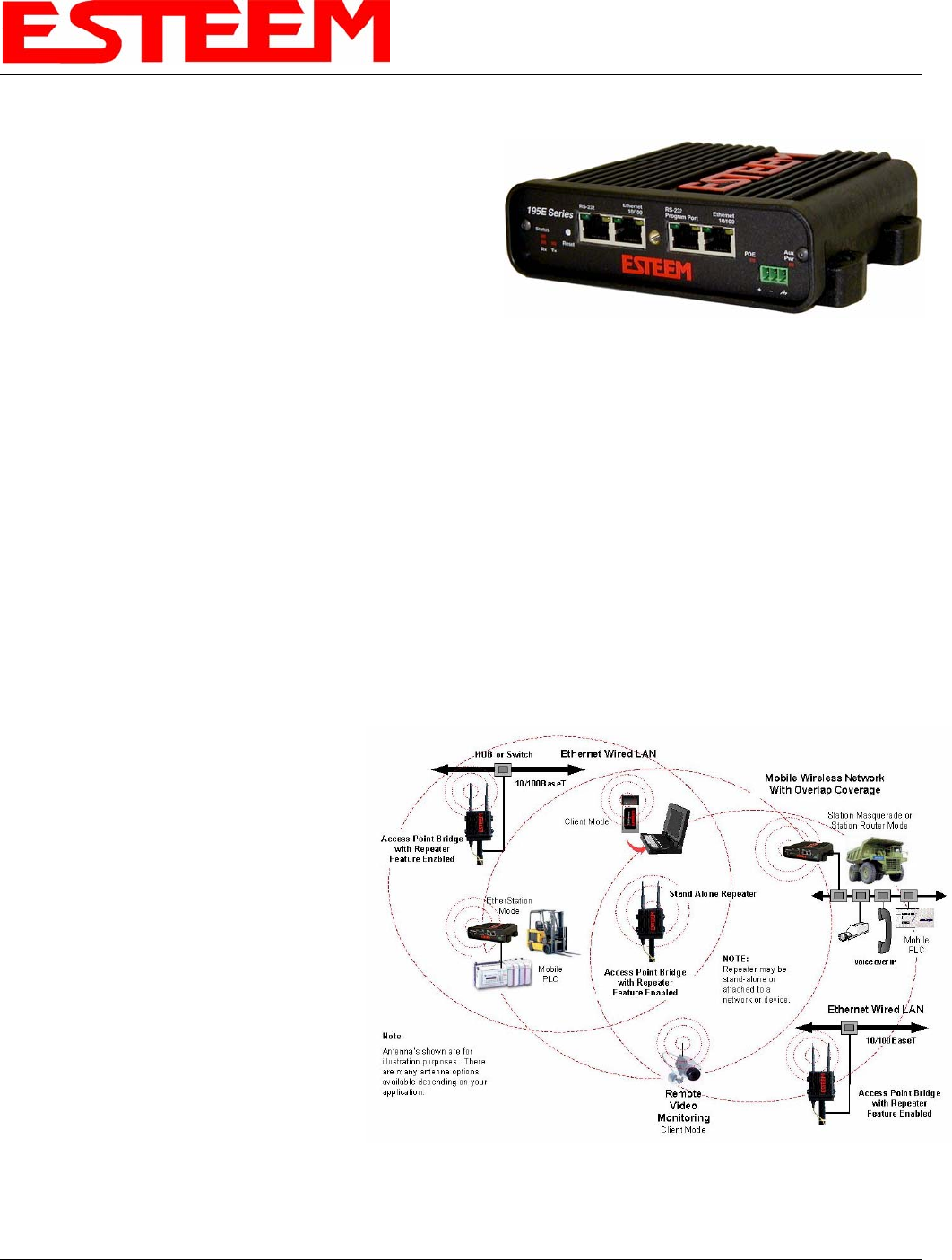
1. Access Point Bridge Mode. When the
Model 195Es is configured as an Access
Point it will provide a wireless bridge
between hardwired Local Area Network
(LAN) networks or individual devices and
simultaneously create a wireless canopy for
the Model 195Es modems in client mode.
Multiple Access Point Bridge modems can be
physically connected to the same network
(LAN) or through a radio link using the
Access Point Repeater mode to provide
overlapping, seamless Ethernet
communication for mobile devices. The
ESTeem Model 195Es in Access Point Bridge mode will pass all network traffic between connected devices including global
network broadcasts. See Figure 1.
2. Access Point Router Mode. In this mode the ESTeem Model 195Es will function as a router between the wired Ethernet
network (connect to the 195Es’ Ethernet port) and the wireless network 195Es’ in repeater peer mode. As in all standard
router configurations, the wireless and wired Ethernet networks will need to be on separate subnets. To communicate from
the wired Ethernet network to devices on the wireless network, a separate router (in addition to the Model 195Es) is required.
The 195Es in Access Point Router mode will pass network traffic for connected devices but will block global network
broadcasts from the wired network. This mode of operation should be used instead of the Access Point Bridge mode when a
separation between networks is required or the ESTeem is connected to larger LAN Networks that will continuously send
global network broadcasts (Figure
2).
3. Access Point Masquerade Mode.
The Access Point Masquerade
mode is a special use of the Access
Point mode where the Model 195Es
will connect clients into a single
static IP address on a wired
network. Data requests from the
wireless network will be processed
through the Access Point
Masquerade 195Es, but any request
from the wired Ethernet network to
devices on the wireless network
will be rejected similar to the
operation of a “firewall”. The
195Es will hide all the IP addresses
connected on the wireless link.
You should use this mode of
Figure 2 – Repeater Mode Diagram
Figure 3- Access Point Masquerade Diagram
CHAPTER 1
INTRODUCTION
Revised: 9 Apr 07 1-3 EST P/N AA107S
operation if Model 195Es is connected directly to the Internet with a static IP address (DSL, T1, etc.) and you want the
wireless clients to access the information through the Model 195Es (Figure 3). This mode should also be used for attaching
the Model 195Es to a network where few IP addresses are available or a firewall for the wireless clients is required.
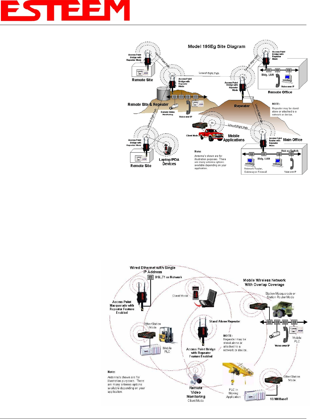
4. Access Point Repeater. The Access Point Repeater is a unique feature available the ESTeem Model 195Es. The Access
Point Repeater can be used with any of the above Access Point modes. With this repeater feature enabled, the Model 195Es
Access Points do not have to be hardwired together on the same physical LAN to provide seamless Ethernet communication
for roaming 195Eg clients. In addition to greatly extending the Access Point canopy range, the Model 195Es will also bridge
any Ethernet device or Ethernet network connected to the unit over this same wireless Ethernet network. This mode gives the
user the features of a point to multi-point bridge network but also allows Model 195Es in the Client mode to simultaneously
roam under the network canopy.
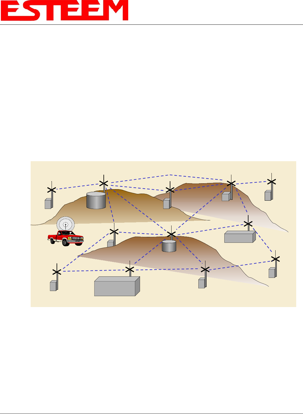
5. Self-Healing Mesh Network. If multiple Access Point Repeater routes are configured to the same destination ESTeem,
the 195Es will create a “self-healing” mesh network by automatically re-routing data through alternate paths to reach its
destination if the primary path is inoperable. The routing and priority of alternate paths is completely user configurable.
See Figure 4.
Station (Client) Modes
6. EtherStation Mode. When the 195Es is configured in the EtherStation Mode and attached to a single Ethernet Device, the
Model 195Es seamless roam under the radio canopy of Access Point and can provide greatly increased range for mobile
Ethernet devices such as vehicles, forklifts, cranes, etc (Figures 1-3).
7. Station Router Mode. The Station Router mode will also function as a mobile client, similar to EtherStation, but will allow
multiple Ethernet devices to be connected to a single 195Es (Figure 3). The 195Es will function as a router between the
wireless client mode and the wired Ethernet devices connected to the Ethernet port. Similar in configuration to the Access
Point Router mode, the wireless and wired Ethernet networks will need to be on separate subnets. To communicate from
wireless network to devices on the wired Station Router network, a separate router (connected to the Ethernet side of the
Access Point) is required. This mode would be used where multiple Ethernet devices will be connected to a single Model
Main Office
Remote Office
Vehicles
Remote Site
Remote Site
Remote Site
Access
Point/Repeater
Access
Point/Repeater
Remote Site
Access
Point/Repeater
Access
Point/Repeater
Access
Point/Repeater
Remote Site
Access
Point/Repeater
Remote Site
Access
Point/Repeater
Remote Site
Access
Point/Repeater
Remote Site
Access
Point/Repeater
Access
Point/Repeater Access
Point/Repeater
Access
Point/Repeater
Remote Site
Remote Site
Client Mode
Figure 4 – Mesh Network Diagram

CHAPTER 1
INTRODUCTION
Revised: 9 Apr 07 1-4 EST P/N AA107S
195Es in a mobile client application and the connected Ethernet devices will need to be accessible from the Access Point’s
LAN network.
8. Station Masquerade Mode. The Station Masquerade Mode is another mode where multiple devices will be connected to a
single ESTeem in a mobile or Client application, but unlike the Station Router mode, the Station Masquerate will consolidate
all connected Ethernet devices to a single IP address on the network. The devices connected to the Station Masquerade 195Es
will be able to access information from both the wireless and wired LAN, but will be inaccessible the other way similar in
application to a firewall. This mode would be used where multiple Ethernet devices will be connected to a single Model
195Es in a mobile application and the IP addresses for each device will be hidden from the LAN connected to the Access
Point. See Figure 3.
To begin setup of your wireless Ethernet network you must first configure the Model 195Es for the mode desired. Chapter 2 will
show several examples of the different modes of operation to help select the correct mode for your application.