GE Medical Systems Information Technologies 340MT WMTS Transmitter User Manual
GE Medical Systems Information Technologies Inc. WMTS Transmitter
Contents
Ex 13a pages 1 to 40
Corometrics Model 340
OPERATOR’S MANUAL MANUAL P/N 2006899-001 REV. A
IUPTOCO
+
~
XXX
340 Telemetry Receiver
REFER TO MANUAL FOR PROPER TRANSDUCERS
ULTRASOUND ECG UA
XXX
340 Telemetry Transmitter

Corometrics Model 340
OPERATOR’S MANUAL MANUAL P/N 2006899-001 REV. A
IUPTOCO
+
~
XXX
340 Telemetry Receiver
REFER TO MANUAL FOR PROPER TRANSDUCERS
ULTRASOUND ECG UA
XXX
340 Telemetry Transmitter

Corometrics and Marquette are registered trademarks of GE Medical Systems Information Technologies. GE is a
registered trademark of General Electric Company. All other product and brand names are trademarks or registered trademarks
of their respective companies. ©2001 GE Medical Systems Information Technologies. All rights reserved. No part of
this manual may be reproduced without the permission of GE Medical Systems Information Technologies.
GUARANTEE
All equipment sold by GE Medical Systems Information Technologies is fully guaranteed as to
materials and workmanship for a period of 1 year. Information Technologies reserves the right to
perform guarantee service operations in its own factory, at an authorized repair station, or in the
customer’s installation.
Our obligation under this guarantee is limited to repairing, or, at our option, replacing any
defective parts of our equipment, except fuses or batteries, without charge, if such defects occur in
normal service.
Claims for damage in shipment should be filed promptly with the transportation company. All
correspondence covering the instrument should specify the model and serial numbers.
GE MEDICAL SYSTEMS Information Technologies
A GE Medical Systems Company
Revision A: 04-01
GE Medical Systems Information Technologies will make available on request such circuit
diagrams, component diagrams, component parts lists, descriptions, calibration instructions, or
other information which will assist the users or appropriately qualified technical personnel to
repair those parts of the equipment which are classified by Information Technologies as
repairable. Refer to the service manual for further information.
CAUTION: In the United States of America, Federal Law restricts this device to sale by or
on the order of a physician.
!
World Headquarters
8200 West Tower Avenue
Milwaukee, WI 53223 USA
Tel: +414.355.5000
800.558.5120 (US only)
Fax: +414.355.3790
Internet: www.gemedicalsystems.com
Europe / Middle East / Africa
Postfach 60 02 65
D-79032 Freiburg Germany
Tel: +49.761.45.43.0
Fax: +49.761.45.43.233
Asia
11th Floor, The Lee Gardens
33 Hysan Avenue
Causeway Bay Hong Kong
Tel: +852.2100.6300
Fax: +852.2100.6292

Revision A Model 340 Telemetry System i
2006899-001
Contents
Figures . . . . . . . . . . . . . . . . . . . . . . . . . . . . . . . . . . . . . . . . . . v
Tables . . . . . . . . . . . . . . . . . . . . . . . . . . . . . . . . . . . . . . . . . . vii
Preface Overview of Telemetry Systems. . . . . . . . . . . . . . . . . . . . . .ix
About Your System . . . . . . . . . . . . . . . . . . . . . . . . . . . . . . . . . . . . . . . . . . . . . . . . . . . . x
Model 340 Original Release . . . . . . . . . . . . . . . . . . . . . . . . . . . . . . . . . . . . . . . . . . . .x
Model 340 Plus . . . . . . . . . . . . . . . . . . . . . . . . . . . . . . . . . . . . . . . . . . . . . . . . . . . . .x
Model 340M . . . . . . . . . . . . . . . . . . . . . . . . . . . . . . . . . . . . . . . . . . . . . . . . . . . . . . . .x
Identifying Your System . . . . . . . . . . . . . . . . . . . . . . . . . . . . . . . . . . . . . . . . . . . . . . . xi
Identifying Model 340 Original Release and Model 340 Plus Telemetry Systems . . xi
Identifying a Model 340M Telemetry System . . . . . . . . . . . . . . . . . . . . . . . . . . . . . xii
1Safety . . . . . . . . . . . . . . . . . . . . . . . . . . . . . . . . . . . . . . . . . 1-1
General Information . . . . . . . . . . . . . . . . . . . . . . . . . . . . . . . . . . . . . . . . . . . . . . . . . . 1-2
General Use . . . . . . . . . . . . . . . . . . . . . . . . . . . . . . . . . . . . . . . . . . . . . . . . . . . . . .1-2
Responsibility of the Manufacturer . . . . . . . . . . . . . . . . . . . . . . . . . . . . . . . . . . . . .1-2
Definitions of Terminology . . . . . . . . . . . . . . . . . . . . . . . . . . . . . . . . . . . . . . . . . . . . 1-3
Equipment Safety Information . . . . . . . . . . . . . . . . . . . . . . . . . . . . . . . . . . . . . . . . . 1-4
Warnings . . . . . . . . . . . . . . . . . . . . . . . . . . . . . . . . . . . . . . . . . . . . . . . . . . . . . . . .1-4
Cautions . . . . . . . . . . . . . . . . . . . . . . . . . . . . . . . . . . . . . . . . . . . . . . . . . . . . . . . . 1-7
Equipment Symbols . . . . . . . . . . . . . . . . . . . . . . . . . . . . . . . . . . . . . . . . . . . . . . . . . 1-8
FCC Information . . . . . . . . . . . . . . . . . . . . . . . . . . . . . . . . . . . . . . . . . . . . . . . . . . . . . 1-9
FCC Rules Compliance . . . . . . . . . . . . . . . . . . . . . . . . . . . . . . . . . . . . . . . . . . . . .1-9
FCC RF Exposure Compliance . . . . . . . . . . . . . . . . . . . . . . . . . . . . . . . . . . . . . . .1-9
FCC Service Information . . . . . . . . . . . . . . . . . . . . . . . . . . . . . . . . . . . . . . . . . . . .1-9
Wireless Medical Telemetry Service . . . . . . . . . . . . . . . . . . . . . . . . . . . . . . . . . 1-10

ii Model 340 Telemetry System Revision A
2006899-001
2Introduction . . . . . . . . . . . . . . . . . . . . . . . . . . . . . . . . . . . . 2-1
Product Summary . . . . . . . . . . . . . . . . . . . . . . . . . . . . . . . . . . . . . . . . . . . . . . . . . . . 2-2
Product Features . . . . . . . . . . . . . . . . . . . . . . . . . . . . . . . . . . . . . . . . . . . . . . . . . . . . 2-3
3Controls, Indicators, and Connectors . . . . . . . . . . . . . . . 3-1
Receiver . . . . . . . . . . . . . . . . . . . . . . . . . . . . . . . . . . . . . . . . . . . . . . . . . . . . . . . . . . . 3-2
Receiver Front Panel . . . . . . . . . . . . . . . . . . . . . . . . . . . . . . . . . . . . . . . . . . . . . . .3-2
Receiver Rear Panel . . . . . . . . . . . . . . . . . . . . . . . . . . . . . . . . . . . . . . . . . . . . . . 3-4
Transmitter . . . . . . . . . . . . . . . . . . . . . . . . . . . . . . . . . . . . . . . . . . . . . . . . . . . . . . . . . 3-6
Transmitter Bottom Panel . . . . . . . . . . . . . . . . . . . . . . . . . . . . . . . . . . . . . . . . . . .3-6
Transmitter Top Panel . . . . . . . . . . . . . . . . . . . . . . . . . . . . . . . . . . . . . . . . . . . . . 3-8
Transmitter Rear Panel Battery Compartment . . . . . . . . . . . . . . . . . . . . . . . . . . 3-10
4Setup Procedures . . . . . . . . . . . . . . . . . . . . . . . . . . . . . . . 4-1
Connecting the Receiver and Monitor . . . . . . . . . . . . . . . . . . . . . . . . . . . . . . . . . . . 4-2
Models 115, 116, 118, 145, 150, 151, and 155 . . . . . . . . . . . . . . . . . . . . . . . . . . .4-2
120 and 170 Series . . . . . . . . . . . . . . . . . . . . . . . . . . . . . . . . . . . . . . . . . . . . . . . 4-5
Setting Up the Transmitter . . . . . . . . . . . . . . . . . . . . . . . . . . . . . . . . . . . . . . . . . . . . 4-7
Installing Batteries . . . . . . . . . . . . . . . . . . . . . . . . . . . . . . . . . . . . . . . . . . . . . . . . .4-7
Attaching the Antenna . . . . . . . . . . . . . . . . . . . . . . . . . . . . . . . . . . . . . . . . . . . . . 4-9
Attaching the Carrying Strap . . . . . . . . . . . . . . . . . . . . . . . . . . . . . . . . . . . . . . . . .4-9
Performing a Functional Checkout . . . . . . . . . . . . . . . . . . . . . . . . . . . . . . . . . . . . 4-10
Initial Conditions . . . . . . . . . . . . . . . . . . . . . . . . . . . . . . . . . . . . . . . . . . . . . . . . . .4-10
Testing the Radio Frequency . . . . . . . . . . . . . . . . . . . . . . . . . . . . . . . . . . . . . . . .4-10
Testing the Ultrasound Functions . . . . . . . . . . . . . . . . . . . . . . . . . . . . . . . . . . . 4-11
Testing the ECG Functions . . . . . . . . . . . . . . . . . . . . . . . . . . . . . . . . . . . . . . . . 4-13
Testing the UA Functions . . . . . . . . . . . . . . . . . . . . . . . . . . . . . . . . . . . . . . . . . . 4-14
Testing the Remote Event Marker Function . . . . . . . . . . . . . . . . . . . . . . . . . . . 4-16
Testing the Environment . . . . . . . . . . . . . . . . . . . . . . . . . . . . . . . . . . . . . . . . . . .4-16

Revision A Model 340 Telemetry System iii
2006899-001
5Monitoring via Telemetry . . . . . . . . . . . . . . . . . . . . . . . . . 5-1
Suggestions for Ambulatory Monitoring . . . . . . . . . . . . . . . . . . . . . . . . . . . . . . . . . 5-2
Monitoring Reminders . . . . . . . . . . . . . . . . . . . . . . . . . . . . . . . . . . . . . . . . . . . . . . . . 5-3
General . . . . . . . . . . . . . . . . . . . . . . . . . . . . . . . . . . . . . . . . . . . . . . . . . . . . . . . . .5-3
Ultrasound . . . . . . . . . . . . . . . . . . . . . . . . . . . . . . . . . . . . . . . . . . . . . . . . . . . . . . .5-3
FECG . . . . . . . . . . . . . . . . . . . . . . . . . . . . . . . . . . . . . . . . . . . . . . . . . . . . . . . . . . .5-3
Tocotransducer . . . . . . . . . . . . . . . . . . . . . . . . . . . . . . . . . . . . . . . . . . . . . . . . . . 5-4
IUP . . . . . . . . . . . . . . . . . . . . . . . . . . . . . . . . . . . . . . . . . . . . . . . . . . . . . . . . . . . . .5-4
6Maintenance . . . . . . . . . . . . . . . . . . . . . . . . . . . . . . . . . . . 6-1
General Cleaning Precautions . . . . . . . . . . . . . . . . . . . . . . . . . . . . . . . . . . . . . . . . . 6-2
Cleaning the Transmitter and Receiver . . . . . . . . . . . . . . . . . . . . . . . . . . . . . . . . . . 6-3
7Troubleshooting . . . . . . . . . . . . . . . . . . . . . . . . . . . . . . . . 7-1
Problem Chart . . . . . . . . . . . . . . . . . . . . . . . . . . . . . . . . . . . . . . . . . . . . . . . . . . . . . . 7-2
8Supplies and Accessories . . . . . . . . . . . . . . . . . . . . . . . . 8-1
General . . . . . . . . . . . . . . . . . . . . . . . . . . . . . . . . . . . . . . . . . . . . . . . . . . . . . . . . . . . . 8-2
Paper . . . . . . . . . . . . . . . . . . . . . . . . . . . . . . . . . . . . . . . . . . . . . . . . . . . . . . . . . . . . . . 8-3
Ultrasound . . . . . . . . . . . . . . . . . . . . . . . . . . . . . . . . . . . . . . . . . . . . . . . . . . . . . . . . . 8-4
FECG . . . . . . . . . . . . . . . . . . . . . . . . . . . . . . . . . . . . . . . . . . . . . . . . . . . . . . . . . . . . . . 8-5
Tocotransducer . . . . . . . . . . . . . . . . . . . . . . . . . . . . . . . . . . . . . . . . . . . . . . . . . . . . . 8-6
IUPC . . . . . . . . . . . . . . . . . . . . . . . . . . . . . . . . . . . . . . . . . . . . . . . . . . . . . . . . . . . . . . 8-7
MECG . . . . . . . . . . . . . . . . . . . . . . . . . . . . . . . . . . . . . . . . . . . . . . . . . . . . . . . . . . . . . 8-8
9Technical Specifications . . . . . . . . . . . . . . . . . . . . . . . . . 9-1
Transmitter . . . . . . . . . . . . . . . . . . . . . . . . . . . . . . . . . . . . . . . . . . . . . . . . . . . . . . . . . 9-2
Receiver . . . . . . . . . . . . . . . . . . . . . . . . . . . . . . . . . . . . . . . . . . . . . . . . . . . . . . . . . . . 9-4

iv Model 340 Telemetry System Revision A
2006899-001
For your notes

Revision A Model 340 Telemetry System v
2006899-001
Figures
Figure Preface-1.
Model 340 or Model 340 Plus REF Number. . . . . . . . . . . . . . . . . . . . . . . . . . . . . . . . . .xi
Figure Preface-2.
Model 340M REF Number . . . . . . . . . . . . . . . . . . . . . . . . . . . . . . . . . . . . . . . . . . . . . . xii
Figure 5-1.
Receiver Front Panel . . . . . . . . . . . . . . . . . . . . . . . . . . . . . . . . . . . . . . . . . . . . . . . . . .3-2
Figure 5-2.
Receiver Rear Panel. . . . . . . . . . . . . . . . . . . . . . . . . . . . . . . . . . . . . . . . . . . . . . . . . . .3-4
Figure 5-3.
Transmitter Bottom Panel. . . . . . . . . . . . . . . . . . . . . . . . . . . . . . . . . . . . . . . . . . . . . . .3-6
Figure 5-4.
Transmitter Top Panel . . . . . . . . . . . . . . . . . . . . . . . . . . . . . . . . . . . . . . . . . . . . . . . . .3-8
Figure 5-5.
Transmitter Rear Panel Battery Compartment . . . . . . . . . . . . . . . . . . . . . . . . . . . . . .3-10
Figure 6-1.
Positioning the Receiver. . . . . . . . . . . . . . . . . . . . . . . . . . . . . . . . . . . . . . . . . . . . . . . .4-2
Figure 6-2.
Attaching the Receiver Antenna. . . . . . . . . . . . . . . . . . . . . . . . . . . . . . . . . . . . . . . . . .4-3
Figure 6-3.
Attaching the Receiver Interconnect Cables. . . . . . . . . . . . . . . . . . . . . . . . . . . . . . . . .4-3
Figure 6-4.
Attaching the Monitor Interconnect Cables. . . . . . . . . . . . . . . . . . . . . . . . . . . . . . . . . .4-4
Figure 6-5.
Attaching the Remote Mark Interconnect Cable. . . . . . . . . . . . . . . . . . . . . . . . . . . . . .4-4
Figure 6-6.
Attaching the Receiver Antenna. . . . . . . . . . . . . . . . . . . . . . . . . . . . . . . . . . . . . . . . . .4-5
Figure 6-7.
Attaching the Monitor Interconnect Cable to a 120 Series Monitor . . . . . . . . . . . . . . .4-6
Figure 6-8.
Attaching the Monitor Interconnect Cable to a 170 Series Monitor . . . . . . . . . . . . . . .4-6
Figure 6-9.
Accessing the Batteries . . . . . . . . . . . . . . . . . . . . . . . . . . . . . . . . . . . . . . . . . . . . . . . .4-7

vi Model 340 Telemetry System Revision A
2006899-001
Figure 6-10.
Transmitter Battery Orientation. . . . . . . . . . . . . . . . . . . . . . . . . . . . . . . . . . . . . . . . . . .4-8
Figure 6-11.
Attaching the Transmitter Antenna. . . . . . . . . . . . . . . . . . . . . . . . . . . . . . . . . . . . . . . .4-9
Figure 6-12.
Attaching the Carrying Strap. . . . . . . . . . . . . . . . . . . . . . . . . . . . . . . . . . . . . . . . . . . . .4-9
Figure 6-13.
Applying Power. . . . . . . . . . . . . . . . . . . . . . . . . . . . . . . . . . . . . . . . . . . . . . . . . . . . . .4-10
Figure 6-14.
Connecting an Ultrasound Transducer. . . . . . . . . . . . . . . . . . . . . . . . . . . . . . . . . . . .4-11
Figure 6-15.
Connecting the Headset. . . . . . . . . . . . . . . . . . . . . . . . . . . . . . . . . . . . . . . . . . . . . . .4-12
Figure 6-16.
Connecting an FECG Cable/Legplate . . . . . . . . . . . . . . . . . . . . . . . . . . . . . . . . . . . .4-13
Figure 6-17.
Connecting a Tocotransducer or IUPC Cable . . . . . . . . . . . . . . . . . . . . . . . . . . . . . .4-14

Revision A Model 340 Telemetry System vii
2006899-001
Tables
Table 3-1.
Definitions of Terminology . . . . . . . . . . . . . . . . . . . . . . . . . . . . . . . . . . . . . . . . . . . . . .1-3
Table 3-2.
Equipment Symbols . . . . . . . . . . . . . . . . . . . . . . . . . . . . . . . . . . . . . . . . . . . . . . . . . . .1-8
Table 3-3.
FCC Rules Compliance . . . . . . . . . . . . . . . . . . . . . . . . . . . . . . . . . . . . . . . . . . . . . . . .1-9
Table 4-1.
Summary of Monitor Parameters . . . . . . . . . . . . . . . . . . . . . . . . . . . . . . . . . . . . . . . . .2-3
Table 5-1.
Receiver Front Panel . . . . . . . . . . . . . . . . . . . . . . . . . . . . . . . . . . . . . . . . . . . . . . . . . .3-3
Table 5-2.
Receiver Rear Panel. . . . . . . . . . . . . . . . . . . . . . . . . . . . . . . . . . . . . . . . . . . . . . . . . . .3-5
Table 5-3.
Transmitter Bottom Panel. . . . . . . . . . . . . . . . . . . . . . . . . . . . . . . . . . . . . . . . . . . . . . .3-7
Table 5-4.
Transmitter Top Panel . . . . . . . . . . . . . . . . . . . . . . . . . . . . . . . . . . . . . . . . . . . . . . . . .3-9
Table 9-1.
Troubleshooting . . . . . . . . . . . . . . . . . . . . . . . . . . . . . . . . . . . . . . . . . . . . . . . . . . . . . .7-2
Table 10-1.
General Supplies . . . . . . . . . . . . . . . . . . . . . . . . . . . . . . . . . . . . . . . . . . . . . . . . . . . . .8-2
Table 10-2.
Paper Supplies . . . . . . . . . . . . . . . . . . . . . . . . . . . . . . . . . . . . . . . . . . . . . . . . . . . . . . .8-3
Table 10-3.
Ultrasound Supplies . . . . . . . . . . . . . . . . . . . . . . . . . . . . . . . . . . . . . . . . . . . . . . . . . . .8-4
Table 10-4.
FECG Supplies. . . . . . . . . . . . . . . . . . . . . . . . . . . . . . . . . . . . . . . . . . . . . . . . . . . . . . .8-5
Table 10-5.
Tocotransducer Supplies . . . . . . . . . . . . . . . . . . . . . . . . . . . . . . . . . . . . . . . . . . . . . . .8-6
Table 10-6.
IUPC Supplies . . . . . . . . . . . . . . . . . . . . . . . . . . . . . . . . . . . . . . . . . . . . . . . . . . . . . . .8-7
Table 10-7.
MECG Supplies . . . . . . . . . . . . . . . . . . . . . . . . . . . . . . . . . . . . . . . . . . . . . . . . . . . . . .8-8

viii Model 340 Telemetry System Revision A
2006899-001
For your notes

Revision A Model 340 Telemetry System ix
2006899-001
Preface
Overview of Telemetry
Systems Preface
This chapter provides an overview of the 340 Series of telemetry systems:
About Your System . . . . . . . . . . . . . . . . . . . . . . . . . . . . . . . . . .x
Identifying Your System . . . . . . . . . . . . . . . . . . . . . . . . . . . . . xi

x Model 340 Telemetry System Revision A
2006899-001
Overview of Telemetry Systems: About Your System
About Your System
Due to continuing product innovations, there are three versions of the
Model 340 Telemetry System in hospitals today. All three versions
operate identically from a user’s perspective. Unless otherwise indicated,
the information in this manual applies to all three devices.
Model 340 Original Release
The first release of the Model 340 Telemetry System operates in the
frequency range 430–470 MHz.
Model 340 Plus
The Model 340 Plus also operates in the frequency range 430–470 MHz
offering additional channel numbers than the original Model 340. In
addition, the Model 340 Plus offers flexibility by allowing factory re-
programming to an alternative channel number should interference
become a factor in your location.
Model 340M
The Model 340M operates in the frequency range 608–614 MHz where
the “M” indicates “medical”. The Model 340M complies with the Federal
Communications Commission (FCC) rules for Wireless Medical
Telemetry Service (WMTS). In June 2000, the FCC allocated a new
spectrum allowing potentially life-critical equipment to operate on an
interference-protected basis. Refer to “Wireless Medical Telemetry
Service” on page 1-10 in this manual for additional information.

Revision A Model 340 Telemetry System xi
2006899-001
Overview of Telemetry Systems: Identifying Your System
Identifying Your System
Each GE Medical Systems Information Technologies device has a unique
serial number tag for identification. For each Model 340 Telemetry
System, a reference number can be used to determine if the unit is a
Model 340 Original Release, Model 340 Plus, or Model 340M. If your
device’s REF number begins with “0”, refer to “Identifying Model 340
Original Release and Model 340 Plus Telemetry Systems” next on this
page. If your device’s REF number begins with “3”, refer to “Identifying a
Model 340M Telemetry System” on the following page.
Identifying Model 340 Original Release and
Model 340 Plus Telemetry Systems
If your device’s REF number beings with “0”:
the fourth character identifies receiver or transmitter
the fifth character identifies Model 340 Original Release or
Model 340 Plus
Refer to Figure 1.
Figure Preface-1. Model 340 or Model 340 Plus REF Number
Example 1: If a serial number label shows REF 0341AAN-501, it is a
receiver from a Model 340 Original Release system.
Example 2: If a serial number label shows REF 0342BBN-XXX00B, it is a
transmitter from a Model 340 Plus system.
0 3 4 _ _ _ _ - _ _ _ _ _ _
Product Code Catalog Number Other Device Characteristics
1 = Telemetry Receiver
2 = Telemetry Transmitter
Version
A = Model 340 Original Release
B = Model 340 Plus
Language/Voltage
Specifiers Three to six characters that
further describe the unit.

xii Model 340 Telemetry System Revision A
2006899-001
Identifying a Model 340M Telemetry System
If your device’s REF number beings with “3”:
the third character identifies receiver or transmitter
the fourth character identifies Model 340M
Refer to Figure 2.
Figure Preface-2. Model 340M REF Number
Example 1: If a serial number label shows REF 341MCCN-XXX00A, it is
a receiver from a Model 340M telemetry system.
Example 2: If a serial number label shows REF 342MBBN-XXX000B, it
is a transmitter from a Model 340M telemetry system.
3 4 _ M _ _ _ - _ _ _ _ _ _
Product Code Catalog Number Other Device Characteristics
1 = Telemetry Receiver
2 = Telemetry Transmitter
Option/Language/Voltage
Specifiers Three to six characters that
further describe the unit.
M = Model 340 Medical

Revision A Model 340 Telemetry System 1-1
2006899-001
Chapter 1
Safety 1
The information presented in this section is important for the safety of
both the patient and operator and also serves to enhance equipment
reliability. This chapter describes how the terms Danger, Warning,
Caution, Important, and Note are used throughout the manual. In
addition, standard equipment symbols are defined.
This section includes the following important information:
General Information. . . . . . . . . . . . . . . . . . . . . . . . . . . . . . . . 1-2
Definitions of Terminology . . . . . . . . . . . . . . . . . . . . . . . . . . 1-3
Equipment Safety Information . . . . . . . . . . . . . . . . . . . . . . . 1-4
Equipment Symbols. . . . . . . . . . . . . . . . . . . . . . . . . . . . . . . . 1-8
FCC Information . . . . . . . . . . . . . . . . . . . . . . . . . . . . . . . . . . 1-9
!

1-2 Model 340 Telemetry System Revision A
2006899-001
Safety: General Information
General Information
General Use
If any equipment is cold to the touch or below ambient temperature,
allow it to stabilize before use.
To ensure patient safety, use only parts and accessories manufactured or
recommended by GE Medical Systems Information Technologies. Parts
and accessories used shall meet the requirements of IEC 601.1.1.
Disposable devices are intended for single use only. They should not be
reused.
Periodically, and whenever the integrity of the equipment is in doubt,
test all functions.
Refer to the "Maternal/Fetal Monitoring Operator’s Manual" for
information concerning the limitations of internal and external fetal
heart rate monitoring techniques.
Responsibility of the Manufacturer
GE Medical Systems Information Technologies (hereinafter Information
Technologies) is responsible for the effects on safety, reliability, and
performance if:
assembly operations, extensions, readjustments, modifications, or
repairs are carried out by persons authorized by Information
Technologies;
the electrical installation of the relevant room complies with the
requirements of appropriate regulations; and
the equipment is used in accordance with the instructions for use.

Revision A Model 340 Telemetry System 1-3
2006899-001
Safety: Definitions of Terminology
Definitions of Terminology
Six types of special notices are used throughout this manual. They are:
Danger, Warning, Caution, Contraindication, Important, and Note. The
warnings and cautions in this safety section relate to the equipment in
general and apply to all aspects of the equipment. Be sure to read the
other chapters because there are additional warnings and cautions which
relate to specific features of the equipment.
When grouped, warnings and cautions are listed alphabetically and do
not imply any order of importance.
Table 1-1. Definitions of Terminology
Danger A DANGER notice indicates an imminently
hazardous situation which, if not avoided, will result
in death or serious injury.
Warning A WARNING indicates a potentially hazardous
situation which, if not avoided, could result in death
or serious injury.
Caution
A CAUTION indicates a potentially hazardous
situation which, if not avoided, may result in minor
or moderate injury. Cautions are also used to
avoid damage to equipment.
Contraindication
A CONTRAINDICATION describes any special
symptom or circumstance that renders the use of a
remedy or the carrying out of a procedure
inadvisable, usually because of a risk.
Important An IMPORTANT notice indicates an emphasized
note. It is something you should be particularly
aware of; something not readily apparent.
Note A NOTE indicates a particular point of information;
something on which to focus your attention.

1-4 Model 340 Telemetry System Revision A
2006899-001
Safety: Equipment Safety Information
Equipment Safety Information
Warnings
:$51,1*6
ACCIDENTAL SPILLS—In the event that fluids are
accidentally spilled on the equipment, take the
equipment out of operation and inspect for damage.
APPLICATION—This equipment is not designed for
direct cardiac connection.
CONDUCTIVE CONNECTIONS—Avoid making any
conductive connections to applied parts (patient
connection) which are likely to degrade safety.
CONDUCTIVE PARTS—Ensure that the conductive
parts of the lead electrodes and associated connectors do
not contact other conductive parts including earth.
CONNECTIONS—The correct way to connect a patient
to the transmitter is to plug the electrode leads into the
patient cable which in turn connects to the
transmitter. The receiver is connected to the wall
socket by the power cord. Do not plug the electrode
leads into the power cord, a wall socket, or an extension
cord.
DEFIBRILLATION—This equipment is not designed for
use with defibrillators.
ELECTRICAL SHOCK—To reduce the risk of electrical
shock, do not remove equipment covers. Refer servicing
to qualified personnel.
ELECTROMAGNETIC INTERFERENCE—Be aware
that strong electromagnetic fields may interfere with
equipment operation. Interference prevents the clear
reception of signals by the device. If the hospital is close
to a strong transmitter such as TV, AM or FM radio,
police or fire stations, a HAM radio operator, an airport,
or cellular phone, their signals could be picked up as
signals by the equipment. If you feel interference is
affecting the equipment, contact your Service
Representative to check the equipment in your
environment.

Revision A Model 340 Telemetry System 1-5
2006899-001
Safety: Equipment Safety Information
:$51,1*6
ELECTROSURGERY—The equipment is not designed
for use with high-frequency surgical devices. In addition,
measurements may be affected in the presence of strong
electromagnetic sources such as electrosurgery
equipment.
EXPLOSION HAZARD—Do not use this equipment in
the presence of flammable anesthetics or inside an
oxygen tent.
GROUNDING—Do not defeat the three-wire grounding
feature of the power cord by means of adaptors, plug
modifications, or other methods. A dangerous shock
hazard to both patient and operator may result.
INSTRUCTIONS—For continued and safe use of this
equipment, it is necessary to follow all listed instructions.
However, the instructions provided in this manual in no
way supersede established medical procedures
concerning patient care. The device does not replace
observation and evaluation of the patient, at regular
intervals, by a qualified care provider who will make
diagnoses and decide on treatments and interventions.
INTERFACING OTHER EQUIPMENT—Monitoring
equipment must be interfaced with other types of medical
equipment by qualified biomedical engineering
personnel. Be certain to consult manufacturers’
specifications to maintain safe operation.
LEAKAGE CURRENT TEST—The interconnection of
auxiliary equipment with this device may increase the
total leakage current. When interfacing with other
equipment, a test for leakage current must be performed
by qualified biomedical engineering personnel before
using with patients. Serious injury or death could result
if the leakage current exceeds applicable standards. The
use of accessory equipment not complying with the
equivalent safety requirements of this equipment may
lead to a reduced level of safety of the resulting system.
Consideration relating to the choice shall include: use of
the accessory in the patient vicinity; and evidence that
the safety certification of the accessory has been
performed in accordance with the appropriate IEC 601.1
and/or IEC 601.1.1 harmonized national standard.

1-6 Model 340 Telemetry System Revision A
2006899-001
Safety: Equipment Safety Information
:$51,1*6
LINE ISOLATION MONITOR TRANSIENTS—Line
isolation monitor transients may resemble actual cardiac
waveforms, and thus cause incorrect heart rate
determinations and alarm activation (or inhibition).
MRI USE—Do not use the equipment during MRI
scanning; conducted current could potentially cause
burns.
PATIENT CABLES AND LEADWIRES—Do not use
patient cables and electrode leads that permit direct
connection to electrical sources. Use only “safety” cables
and leadwires. Use of non-safety patient cables and lead
wires creates risk of inappropriate electrical connection
which may cause patient shock or death.
PACEMAKER PATIENTS—Rate meters may continue to
count the pacemaker rate during occurrences of cardiac
arrest or some arrhythmias. Do not rely entirely upon
rate meter alarms. Keep pacemaker patients under close
surveillance. Refer to your monitor’s operator’s manual
for disclosure of the pacemaker pulse rejection capability.
SIMULTANEOUS DEVICES—Do not simultaneously
connect more than one device that uses electrodes to
detect ECG and/or respiration to the same patient. Use
of more than one device in this manner may cause
improper operation of one or more of the devices.
STRANGULATION—Make sure all patient cables,
leadwires, and tubing are positioned away from the
patient’s head to minimize the risk of accidental
strangulation.
WATER BIRTHS—Do not use a fetal or maternal/fetal
monitor to directly monitor patients during water
births, in whirlpool or submersion water baths, during
showers, or in any other situation where the mother is
immersed in water. Doing so may result in electrical
shock hazard.

Revision A Model 340 Telemetry System 1-7
2006899-001
Safety: Equipment Safety Information
Cautions
&$87,216
ANNUAL SERVICING—For continued safety and
performance of the equipment, it is recommended that
the calibration, accuracy, and electrical safety of the
equipment be verified on an annual basis by an
Information Technologies Service Representative.
DAILY INSPECTION—It is essential that the
equipment and accessories be inspected prior to every
use.
ENVIRONMENT—The performance of the equipment
has not been tested in certain areas, such as x-ray and
imaging suites. The equipment is not recommended for
use in these environments.
PERFORMANCE—Report all problems experienced with
the equipment. If the equipment is not working properly,
contact your Service Representative for service. The
equipment should not be used if it is not working
properly.
1-8 Model 340 Telemetry System Revision A
2006899-001
Safety: Equipment Symbols
Equipment Symbols
The following is a list of symbols used on products manufactured by
Information Technologies. Some symbols may not appear on your
equipment.
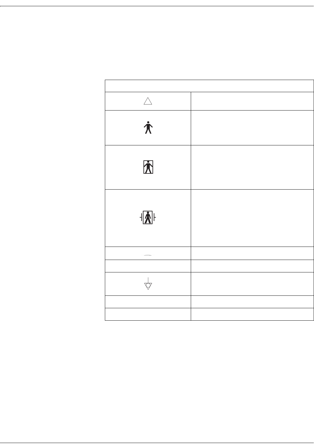
Table 1-2. Equipment Symbols
ATTENTION: Consult accompanying documents.
TYPE B EQUIPMENT. Type B equipment is
suitable for intentional external and internal
application to the patient, excluding direct cardiac
application.
TYPE BF EQUIPMENT. Type BF equipment is
suitable for intentional external and internal
application to the patient, excluding direct cardiac
application. Type BF equipment has an F-type
applied part.
DEFIBRILLATOR-PROOF TYPE BF EQUIPMENT:
Type BF equipment is suitable for intentional
external and internal application to the patient,
excluding direct cardiac application. Type BF
equipment is type B equipment with an F-type
isolated (floating) part. The paddles indicate the
equipment is defibrillator proof.
ALTERNATING CURRENT (AC).
IPX1 DRIP PROOF.
EQUIPOTENTIALITY.
OPOWER OFF: disconnection from the mains.
IPOWER ON: connection to the mains.
!

Revision A Model 340 Telemetry System 1-9
2006899-001
Safety: FCC Information
FCC Information
FCC Rules Compliance
This equipment complies with the FCC rules shown in Table 1-3. (Refer
to “Identifying Your System” on page xi for information about identifying
what type of telemetry system you have in your hospital.) Operation is
subject to the condition that this device does not cause harmful
interference.
FCC RF Exposure Compliance
,03257$17
RF EXPOSURE—To comply with FCC RF exposure
compliance requirements, users should avoid grasping
the antenna for any extended period of time while the
device is in operation.
FCC Service Information
Servicing the radio frequency transmitter and receiver sections of the
Model 340 Telemetry System requires an FCC General Radio Telephone
License.
Any changes or modifications made to the Model 340 Telemetry System
that are not expressly approved by Information Technologies, could void the
user’s authority to operate this equipment.
Table 1-3. FCC Rules Compliance
Telemetry Transmitter Receiver
Model 340 Original Release Part 90 Part 15
Model 340 Plus Part 90 Part 15
Model 340M Part 95 Part 15

1-10 Model 340 Telemetry System Revision A
2006899-001
Safety: FCC Information
Wireless Medical Telemetry Service
This section applies to Model 340M Telemetry Systems only. Refer to
“Identifying Your System” on page xi for information about identifying
what type of telemetry system you have in your hospital.
,03257$17
Operation of a Model 340M Telemetry System requires
prior coordination with a frequency coordinator
designated by the FCC for the Wireless Medical
Telemetry Service.
In June 2000, the FCC allocated new spectrum and established rules for
Wireless Medical Telemetry Service (WMTS) allowing potentially life-
critical equipment to operate on an interference-protected basis.
The frequency allocation for WMTS provides spectrum where the
equipment can operate on a primary basis increasing the reliability of
this important service. The FCC allocated 14 MHz of spectrum for use by
medical telemetry equipment in the 608–614 MHz, 1395–1400 MHz, and
1429–1432 MHz bands. This allocation was based on a needs assessment
conducted by the American Hospital Association (AHA).
The 608–614 MHz band, which corresponds to TV channel 37 had been
reserved for radio astronomy uses, so this action elevates medical
telemetry to a co-primary status with radio astronomy in this band. The
1395–1400 MHz and 1429–1432 MHz bands were government bands
reallocated for non-government use.
WMTS is designated as one of the Citizen’s Band Services in Part 95 of
the rules and licensed by rule to eliminate the possible costs and delays
to obtain individual operator’s licenses. The medical telemetry
equipment is authorized under the certification procedure in Part 2 of
the rules. One or more frequency coordinators maintain a database of all
equipment used in conjunction with WMTS.
For more information visit http://www.fcc.gov.


2-2 Model 340 Telemetry System Revision A
2006899-001
Introduction: Product Summary
Product Summary
The Corometrics Model 340 Telemetry System (receiver and transmitter)
provides a wireless means of transmitting heart rate and uterine activity
signals from an ambulatory mother to a bedside fetal or maternal/fetal
monitor. The system operates with the following Corometrics brand
monitors; if your monitor is not listed, check with your saleperson or
service representative for a more current list.
Model 115
Model 116
Model 118
120 Series*
Model 145
Model 150
Model 151
Model 155
170 Series
127(The Model 340 Telemetry
System does not support fetal
movement detection.
The system monitors ultrasound, ECG (FECG or MECG), and uterine
activity (TOCO or IUPC) signals individually or in combination—
depending on which parameters are available in the fetal or maternal/
fetal monitor. Refer to your monitor’s operator’s manual as needed.
*A 120 Series Monitor requires a Communications Board in order to interface to a Model 340 Telemetry System. If
your monitor does not have this option, an upgrade kit is available as cat. no. (REF) 1559BAO. Contact your
Service Representative for more information.

Revision A Model 340 Telemetry System 2-3
2006899-001
Introduction: Product Features
Product Features
The following is a summary of product features:
Battery operated transmitter provides up to 20 hours* of continuous
transmission when operated with fresh batteries.
A Low Battery indicator, accompanied by an audio indicator, signals
an impending low-battery condition.
A transmitter headset* allows the patient or staff to hear the
ultrasonically detected heartbeats for reassurance as well as to verify
proper transducer placement.
A Signal Quality indicator verifies the strength of the radio
transmission signal.
Transducers are quickly and easily interchangeable amongst the
Model 340 Telemetry System and most Corometrics brand monitors:
Models 116, 118, 150, 151, 155, and 170 Series: transducers are
interchangeable.
120 Series: ECG rectangular connector cables are not compatible;
round connector cables are compatible.
Models 115 and 145: cat. no. (REF) 5600 ultrasound transducers
cannot be used with a Model 340. Use only cat. no. (REF) 5700
transducers when the using a Model 115 or 145 with a Model 340
Telemetry System.
Provides simultaneous monitoring of two heart rates (twins or
maternal/fetal) when used with a monitor supporting these
parameters. Refer to Table 2-1 for a summary of monitor parameters.
,03257$17
INSTRUCTIONS—The operator should review and be
familiar with the operator’s manual for the fetal or
maternal/fetal monitor as well as the “Maternal/Fetal
Monitoring Operator’s Manual”.
*Use of the headset will deplete the batteries more rapidly.
Table 2-1. Summary of Monitor Parameters
115 116 118 126 128 129 145 150 151 151D 155 171 172 173 174
TOCO ááááááááá á ááááá
IUPC áááááá áá áá
US ááááááááá á ááááá
FECG áááááá áá áá
MECG ááá ááá

2-4 Model 340 Telemetry System Revision A
2006899-001
For your notes

Revision A Model 340 Telemetry System 3-1
2006899-001
Chapter 3
Controls, Indicators, and
Connectors 3
This section describes all controls, indicators, and connectors on a Model
340 Telemetry System.
Receiver. . . . . . . . . . . . . . . . . . . . . . . . . . . . . . . . . . . . . . . . . . 3-2
Transmitter . . . . . . . . . . . . . . . . . . . . . . . . . . . . . . . . . . . . . . 3-6
3-2 Model 340 Telemetry System Revision A
2006899-001
Controls, Indicators, and Connectors: Receiver
Receiver
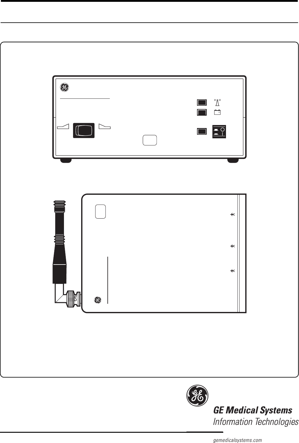
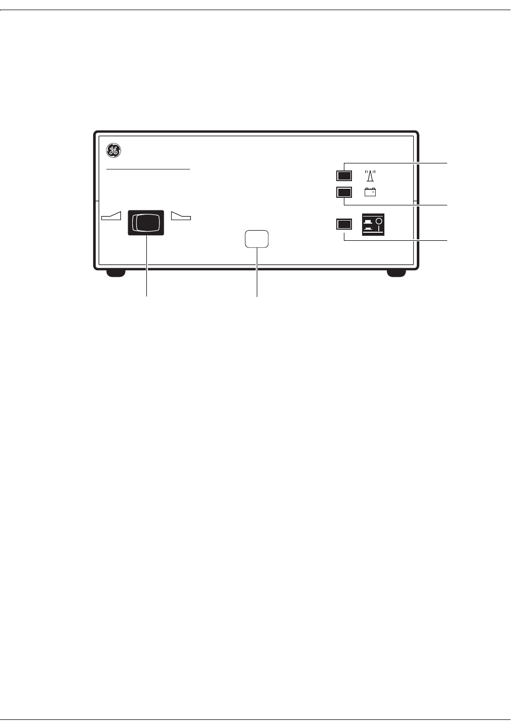
Receiver Front Panel
Figure 3-1. Receiver Front Panel
IUPTOCO
+
~
XXX
340 Telemetry Receiver
AB
C
D
E

Revision A Model 340 Telemetry System 3-3
2006899-001
Controls, Indicators, and Connectors: Receiver
Table 3-1. Receiver Front Panel
Name Description
AUA Mode Selector
Switch
This switch communicates the active uterine
activity mode to the fetal or maternal/fetal monitor:
When monitoring with a tocotransducer, set the
switch to the TOCO position.
When monitoring with an intrauterine pressure
catheter, set the switch to the IUP position.
B Channel Number
The channel number is the customer-designated
receiving frequency of the receiver. For each
telemetry system, the channel number of the
receiver must be identical to the channel number of
the transmitter. Also, if you have more than one
telemetry system, or other RF devices, each
system must have a unique channel number.
CPower Switch and
Indicator
The Power switch turns the receiver on (I) and off
(O). When set to on, the green Power indicator
illuminates.
D Low Battery Indicator
The red Low Battery indicator flashes when you
have approximately 10 minutes of transmitter
battery power remaining. The Low Battery indicator
stops flashing and lights continuously as soon as
the battery is depleted.
E Signal Indicator
The green Signal indicator lights continuously
when the receiver is accepting radio frequency
signals from the transmitter. The Signal indicator
flashes if the signal strength is weak or marginal.
3-4 Model 340 Telemetry System Revision A
2006899-001
Controls, Indicators, and Connectors: Receiver
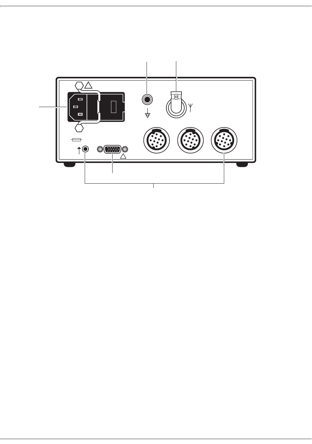
Receiver Rear Panel
Note: Antenna shown removed.
Figure 3-2. Receiver Rear Panel
ANTENNA
OUTPUTS TO MONITOR
CONNECT TO
COROMETRICS
MONITORS ONLY
ULTRASOUND ECG UA
!
WARNING: TO REDUCE FIRE HAZARD
REPLACE FUSE AS MARKED.
CAUTION
!
120Vac
~
120V ~ 50-60HZ 30W
0.25A SLOW BLOW
A
ED
C
B

Revision A Model 340 Telemetry System 3-5
2006899-001
Controls, Indicators, and Connectors: Receiver
Table 3-2. Receiver Rear Panel
Name Description
AAC Line Connector and
Fuseholder Module
This module houses the AC-line input connector
and the main fuses for the receiver:
100–120 VAC: requires two, 0.25 A slow-blow
fuses.
220–240 VAC: requires two, 0.2 A time-lag
fuses.
BAuxiliary Output
Connector
This connector is used with 120 and 170 Series
Monitors only. Do not use this connection method
for Models 115, 116, 118, 145, 150, 151, and 155
Monitors.
This connector outputs the US, ECG, UA, and
Mark signals, acquired by telemetry, to a 120 or
170 Series Monitor. See page 4-5 for complete
interconnection details.
As soon as any telemetry mode is detected, the
front panel of the 120 or 170 Series Monitor is
disabled and all front panel inputs are ignored.
In other words, telemetry and monitor modes
cannot be “mixed and matched’; you must use
telemetry only or direct monitoring only.
For proper operation with a 170 Series Monitor,
disconnect all transducers from the front panel
of the monitor.
CUS, ECG, UA, and Mark
Connectors
These connectors are used with Models 115, 116,
118, 145, 150, 151, and 155 Monitors only. Do not
use this connection method for 120 and 170 Series
Monitors.
Each connector outputs the respective signal,
acquired by telemetry, to the fetal or maternal/fetal
monitor:
US: light grey connector which outputs the
ultrasound signal.
ECG: grey connector which outputs the FECG or
MECG signal.
UA: white connector which outputs the TOCO or
IUPC signal.
Mark: connector which outputs the Event Mark
signal.
See page 4-2 for complete interconnection details.
D Antenna Connector Twist-on connector for attaching the receiver
antenna.
E Equipotential Lug Binding post terminal directly connected to the
chassis for use as an equipotentiality connection.
3-6 Model 340 Telemetry System Revision A
2006899-001
Controls, Indicators, and Connectors: Transmitter
Transmitter
Transmitter Bottom Panel
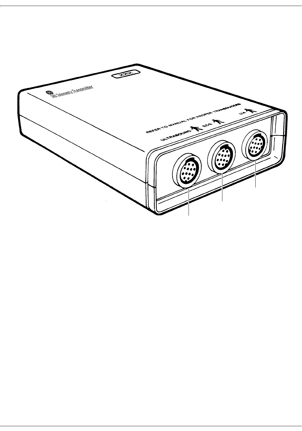
Figure 3-3. Transmitter Bottom Panel
A
C
B

Revision A Model 340 Telemetry System 3-7
2006899-001
Controls, Indicators, and Connectors: Transmitter
Table 3-3. Transmitter Bottom Panel
Name Description
A Ultrasound Input
Connect a Corometrics 5700 Series pulsed
Doppler ultrasound transducer to this light gray
receptacle.
Corometrics 5600 Series continuous-wave
ultrasound transducers are not compatible with
the Model 340 Telemetry System. The 5600
Series Transducer was designed for use with
Models 115 and 145 Monitors and Models 320
and 330 Telemetry Systems.
B ECG Input
Connect an FECG cable/legplate or MECG cable
plug to this grey receptacle. This connector is
compatible with all round-connector FECG/MECG
patient cables used with Corometrics-brand
monitors.
C UA Input Connect a tocotransducer, IUPC, or strain gauge
transducer plug to this white receptacle. Contact
your Sales Representative about compatibility.

3-8 Model 340 Telemetry System Revision A
2006899-001
Controls, Indicators, and Connectors: Transmitter
Transmitter Top Panel
Note: Antenna shown removed.
Figure 3-4. Transmitter Top Panel
ABCDEA

Revision A Model 340 Telemetry System 3-9
2006899-001
Controls, Indicators, and Connectors: Transmitter
Table 3-4. Transmitter Top Panel
Name Description
A Loops Loops for attaching the carrying strap.
B Headset Connector Connect the headset to this receptacle to listen to
the fetal heart rate derived from ultrasound.
CRemote Event Mark
Connector
Connect a Corometrics Remote Event Marker to
this receptacle. When the marker’s button is
pressed for at least one second, an event mark
signal is transmitted and one of the following marks
prints on the strip chart paper:
: This annotation is commonly used to record
an “event.” This mark is available on all
Corometrics-brand monitors.
: This annotation is commonly used as an
indication that the mother has perceived fetal
movement. (Refer to your monitor’s operator’s
manual to learn if your monitor supports this
feature. Refer to your monitor’s service manual
for information about enabling the option.)
D Power Switch Moving the switch to the on position (I) turns on the
transmitter; moving the switch to the off position
(O), turns off the transmitter.
E Antenna Connector Twist-on connector for attaching the transmitter
antenna.
F
M
3-10 Model 340 Telemetry System Revision A
2006899-001
Controls, Indicators, and Connectors: Transmitter
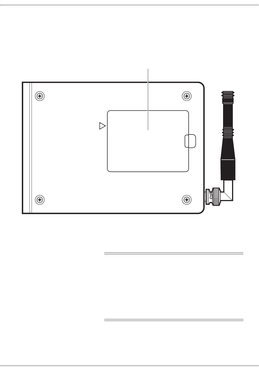
Transmitter Rear Panel Battery Compartment
Figure 3-5. Transmitter Rear Panel Battery Compartment
The battery compartment holds four “AA” alkaline batteries.
&$87,21
BATTERY STRENGTH—When the battery power is low,
the transmitter emits a chirping sound every 4–5
seconds. (For Model 340 Plus and Model 340M Systems,
the frequency of chirping increases as the batteries
become depleted.) The onset of chirping signals
approximately 10 minutes of remaining battery power.
The chirping continues until the battery power is
completely depleted, at which time the transmitter stops
sending data.
DANGER: POSSIBLE EXPLOSION HAZARD IF USED
IN THE PRESENCE OF FLAMMABLE ANESTHETICS.
CAUTION: REFER SERVICE ONLY TO QUALIFIED PERSONNEL
!
BATTERY COMPARTMENT
Battery Compartment