GE Medical Systems Information Technologies 340MT WMTS Transmitter User Manual Ex 13f simple inst 340
GE Medical Systems Information Technologies Inc. WMTS Transmitter Ex 13f simple inst 340
Contents
Ex 13f simple inst 340

Simplified Operating Instruction, 340M OB Telemetry, 608-614MHz
GE Medical Systems Information Technologies 4/9/01
Page 1 of 8
340M OB Telemetry Simplified Operating Instructions
Overview:
The 340M OB Telemetry system is comprised of a transmitter and receiver to provide an RF link between
patient worn transducers and fetal monitor, allowing patient to freely move about while staff monitor fetal
heart rate and uterine contractions remotely.
The 341 Receiver is line powered from 120 VAC, and the 342 Transmitter is powered from (4) AA size
primary Alkaline cells. Expected life of the Alkaline cells in continuous use is roughly 16 Hrs.
There are two simulators used for exercising the transmitter. One is a production simulator (Model 325)
and the other is a radiation hardened simulator (built into a metal box). The 325 simulator will be used for
SAR testing and the radiation hardened will be used for other testing.
Other accessories are provided for their use in testing, if necessary.
Descriptions: (refer also to 340 Service manual, pages 3-2,3,4)
341 Receiver:
Front Panel:
AC power switch far right
Toco/Iup mode change switch left
Indicator lamps center right
Signal strength indicator, green top
Battery status, red center
AC mains, green bottom
Rear Panel:
Power Entry Module far left top
Mark interconnect cable Jack far left bottom
System Interconnect cable jack left bottom
Ultrasound interconnect cable jack bottom center
ECG interconnect cable jack bottom right
UA interconnect cable jack bottom far right
Equipotential ground jack top center

Simplified Operating Instruction, 340M OB Telemetry, 608-614MHz
GE Medical Systems Information Technologies 4/9/01
Page 2 of 8
Antenna jack (RA female BNC) top center
Connect to ¼ wave stainless whip
342 Transmitter:
Front Panel:
Ultrasound Transducer jack left
ECG Transducer jack center
UA transducer jack right
Rear Panel:
Headphone jack far left
Remote mark transducer jack left
Power switch right
Antenna jack (BNC) far right
Connect to ¼ wave helical wound ant.
Bottom Panel:
Battery access door
Radiation Hardened Simulator (for use at ITS, Boxborough):
This is an aluminum die-cast box containing (2) Alkaline ‘D’ cells providing power, and active circuitry
providing signal to the 5700 Ultrasound Transducers and UA Transducer plug.
Top:
Power switch:
Must be in the ‘ON’ position to obtain simulated transducer signal. Turn ‘OFF’ when not
needed to conserve battery.
UA Ref pushbutton:
Forces UA simulated signal to a baseline level for physiologic signal drift testing. Not
used for RF testing.
Adjustment Potentiometer:
Allows UA simulated signal to be offset from baseline level by adjustable amount. Not
used for RF testing.

Simplified Operating Instruction, 340M OB Telemetry, 608-614MHz
GE Medical Systems Information Technologies 4/9/01
Page 3 of 8
Side:
(4) Gray Cables total
- Gray cable, no plug:
Not used
-Gray cable, 5700 Transducer at end, nothing beyond
Not used
-Gray cable, 5700 Transducer at end, mechanically face connected to slave 5700
transducer
This slave 5700 plug connects to Ultrasound input jack of the 342 transmitter.
-Gray cable, round 12 pin white connector at end
This plugs into the UA connector jack of the 342 Transmitter.
325 Maternal/Fetal Simulator (for use at ITS, Menlo Park, SAR):
Front Panel:
FECG/MECG section:
RATE bpm:
Set to 120
QRS AMPLITUDE:
Set to 2000
CMR: Set to BAL
MODE: Set to FECG
QRS POLARITY:
Set to (+)
ULTRASOUND/FMD section:
RATE bpm:
Set to 120
SIGNAL LEVEL:
Set to HIGH
MODE: Set to US/FMD
UA Section
Black Slide Switch:
Simplified Operating Instruction, 340M OB Telemetry, 608-614MHz
GE Medical Systems Information Technologies 4/9/01
Page 4 of 8
Left position
LEVEL mmHg:
Set to 100
MODE: Set to TOCO
Bottom Center section
MANUAL ADJUSTMENT:
Full clockwise
PATTERN MEMORY:
ON
Bottom Right
POWER indicator:
Glows green when AC power connected and rear panel switch depressed
Rear Panel:
Power inlet:
Connect IEC style power cord to 120 VAC
Power button:
Push on/ Push off style button. 325 must be powered on for testing.
Cable Harness, Front Panel:
From Top Center (3) gray cables are connected from ‘CONNECT TO FETAL MONITOR’
connector. -Round white to UA input jack of 341 Transmitter
-Round Gray/Blue to ULTRASOUND input jack of 341 Transmitter
-Round dark gray to ECG input jack of 341 Transmitter
Procedure:
1) Identify packed items.
- 341M Telemetry Receiver
- Line cord
- System Interconnect cable #1563AAO
- Mark interconnect cable #1397AAO
- US interconnect cable #1399BAO
- ECG interconnect cable #1375AAO
- UA interconnect cable #1400AAO
- Quarter wave stainless whip antenna (receiver)
Simplified Operating Instruction, 340M OB Telemetry, 608-614MHz
GE Medical Systems Information Technologies 4/9/01
Page 5 of 8
- 342M Telemetry Transmitter
- Black Helical antenna (transmitter)
- 3 sets of AA batteries
- Remote Mark transducer #3919BAO
- Softrans Cable #1336AAO
- Softrans Intrauterine Pressure Catheter #2076AAO
- Ultrasound Transducer #5700AAX
- Toco transducer, #2264LAX
- Headset #3316AAO
- Qwik Connect Plus Legplate interface cable, #1590AAO
- Radiation Hardened Simulator, (no marking) Boxborough site
- Model 325 Simulator, Menlo Park site
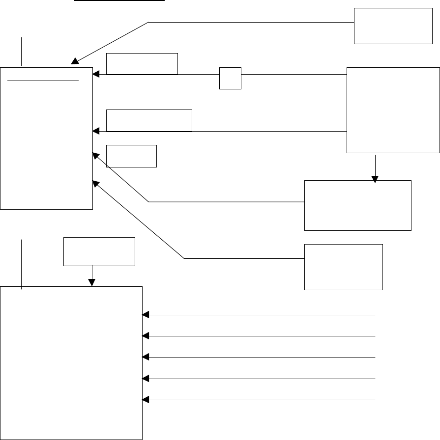
2) For tests involving fully modulated transmitter signals, interconnect system as shown:
Boxborough, MA:
Helical Ant.
(2) 5700 transducers
face to face
stainless
whip ant.
System Interconnect cable #1563AAO
Mark interconnect cable #1397AAO
US interconnect cable #1399BAO
ECG interconnect cable #1375AAO
UA interconnect cable #1400AAO
342M Transmitter
(power switch on)
Boxborough:
RF Hardened
Simulator
(Power switch on)
Ultrasound
Uterine Activity
1590AAO Legplate
341M Receiver
(power switch on)
(green signal strength LED
indicates transmitter active)
AC Power Remote Mark
pushbutton
(3919BAO)
Headset
(3316AAO)
ECG
Simplified Operating Instruction, 340M OB Telemetry, 608-614MHz
GE Medical Systems Information Technologies 4/9/01
Page 6 of 8
3) Description of System as connected above.
Input to modulate transmitter is derived from simulator. Can be monitored via headset.
Uterine activity modulation derived from simulator.
ECG modulation derived from simulator.
Helical antenna radiates modulated RF to 341 Receiver.
341 Receiver intercepts RF via ¼ wave stainless whip antenna.
341 Receiver signal strength LED indicates transmitter active.
Simplified Operating Instruction, 340M OB Telemetry, 608-614MHz
GE Medical Systems Information Technologies 4/9/01
Page 7 of 8
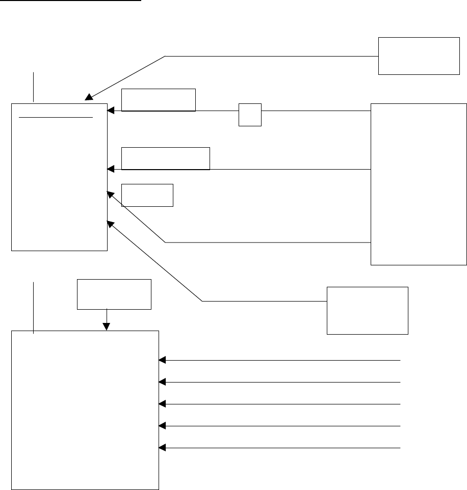
Menlo Park Configuration:
Helical ant.
stainless
whip
System Interconnect cable #1563AAO Open (5)
Mark interconnect cable #1397AAO
US interconnect cable #1399BAO
ECG interconnect cable #1375AAO
UA interconnect cable #1400AAO
342M Transmitter
(power switch on)
Menlo Park:
Model 325
Simulator
(Power switch on)
Ultrasound
Uterine Activity
341M Receiver
(power switch on)
(green signal strength LED
indicates transmitter active)
AC Power Remote Mark
pushbutton
(3919BAO)
ECG
Headset
(3316AAO)
Simplified Operating Instruction, 340M OB Telemetry, 608-614MHz
GE Medical Systems Information Technologies 4/9/01
Page 8 of 8
3) Description of System as connected above.
Input to modulate transmitter is derived from simulator. Can be monitored via headset.
Uterine activity modulation derived from simulator.
ECG modulation derived from Model 325 simulator.
Helical antenna radiates modulated RF to 341 Receiver.
341 Receiver intercepts RF via ¼ wave stainless whip antenna.
341 Receiver signal strength LED indicates transmitter active.