GE Medical Systems Information Technologies 340MT WMTS Transmitter User Manual
GE Medical Systems Information Technologies Inc. WMTS Transmitter
Contents
Ex 13a pages 41 to 82

Revision A Model 340 Telemetry System 4-1
2006899-001
Chapter 4
Setup Procedures 4
This section contains step-by-step instructions for connecting and testing
your Model 340 Telemetry System.
,03257$17
CHANNEL NUMBERS—Ensure that the receiver and
transmitter are operating on the same frequency; the
channel numbers must be identical. The channel number
label is located on the front of the receiver and on the side
of the transmitter.
If you have more than one telemetry system, make sure
that each transmitter/receiver pair operates on a unique
frequency.
Connecting the Receiver and Monitor. . . . . . . . . . . . . . . . . . 4-2
Setting Up the Transmitter. . . . . . . . . . . . . . . . . . . . . . . . . . 4-7
Performing a Functional Checkout. . . . . . . . . . . . . . . . . . . 4-10
4-2 Model 340 Telemetry System Revision A
2006899-001
Setup Procedures: Connecting the Receiver and Monitor
Connecting the Receiver and Monitor
There are two types of interconnection methods depending on the model
of your fetal or maternal/fetal monitor. Check your monitor model
number prior to making any connections.
Models 115, 116, 118, 145, 150, 151, and 155
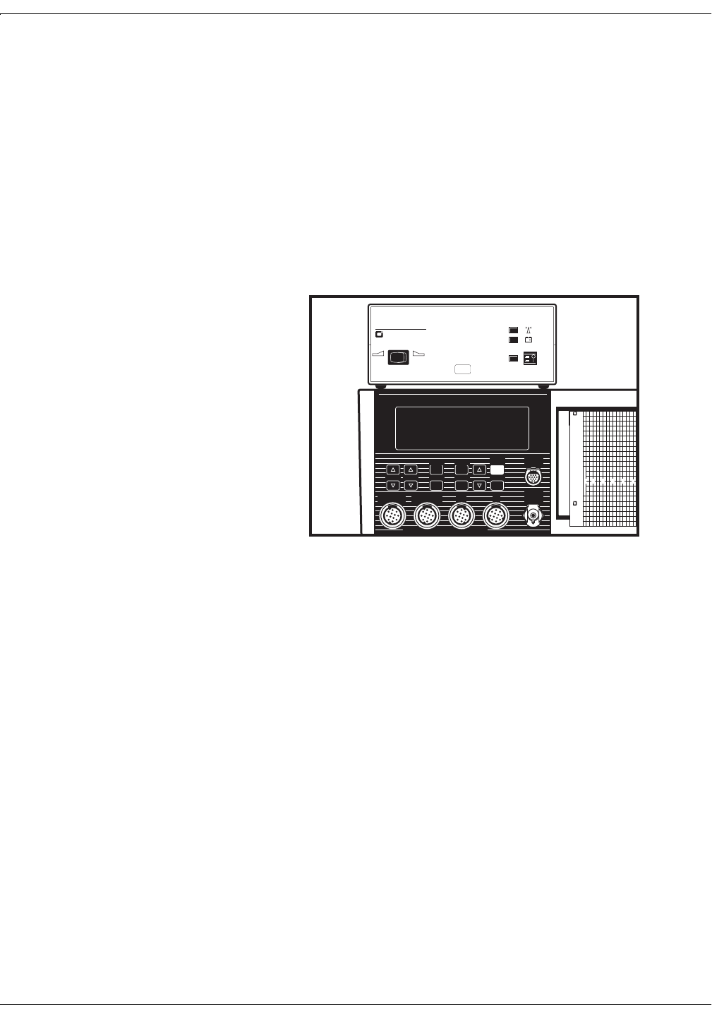
1. Turn off both the monitor and the receiver.
2. Place the receiver on top of, or near, the monitor.
Note: Model 118 shown.
Figure 4-1. Positioning the Receiver
MATERNAL / FETAL MONITOR
118
Maternal
BP
ULTRASOUND ULTRASOUND 2 ECG
ECG
UA
ECG AND SpO2 ELECTRICALL
ELECTRICALL
Y ISOLATED
REFER TO MANUAL FOR PROPER TRANSDUCERS
Volume Volume BP Stop Setup Select
BP Start
Start
BP Auto
Alarm
Alarm
Cancel
Maternal
Maternal
SpO2
4305AAO
COROMETRICS MEDICAL SYSTEMS,
4305AAO
FHR bpm
90
120
150
180
240
210
IUPTOCO
Telemetry Receiver
340R
+
COROMETRIC
XX
X
Revision A Model 340 Telemetry System 4-3
2006899-001
Setup Procedures: Connecting the Receiver and Monitor
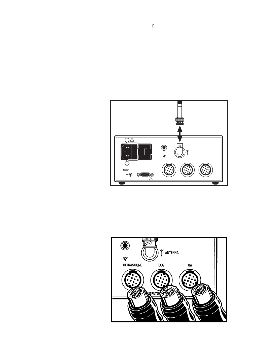
3. Insert the receiver antenna (longer of the two antennas) into the rear
panel Antenna connector ; rotate the attachment collar in a
clockwise direction until snug.
127(A Remote Antenna Bracket, cat. no. (REF) 1441AAO, is
available for attaching the antenna when the receiver will be
enclosed in a cart or cabinet. Refer to the Installation
Instructions, part no. (REF) 14153AA, included with the
bracket; or contact your Biomedical Engineering Department
for assistance. To attach the antenna to the BNC connector
on the bracket, rotate the antenna attachment collar in a
clockwise direction until snug.
Figure 4-2. Attaching the Receiver Antenna
4. Connect the appropriate ultrasound, ECG, and uterine activity
interconnect cables to the corresponding Ultrasound, ECG, and UA
connectors on the receiver rear panel.
Figure 4-3. Attaching the Receiver Interconnect Cables
ANTENNA
OUTPUTS TO MONITOR
CONNECT TO
COROMETRICS
MONITORS ONLY
ULTRASOUND ECG UA
!
WARNING: TO REDUCE FIRE HAZARD
REPLACE FUSE AS MARKED.
CAUTION
!
120Vac
~
120V ~ 50-60HZ 30W
0.25A SLOW BLOW
4-4 Model 340 Telemetry System Revision A
2006899-001
Setup Procedures: Connecting the Receiver and Monitor
5. Connect the remaining ends of the cables to the color-coded
Ultrasound, ECG, and UA input connectors on the front or side panel of
the monitor.
Note: Model 118 shown.
Figure 4-4. Attaching the Monitor Interconnect Cables
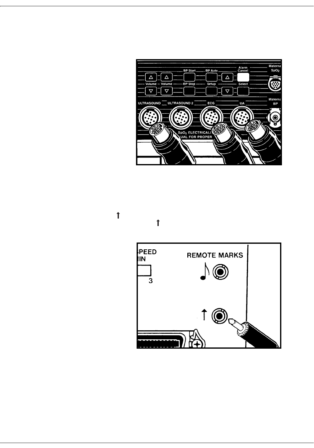
6. Connect one end of the Remote Event Mark interconnect cable to the
connector on the receiver rear panel; connect the other end to the
Remote Marks connector on the rear or side panel of the monitor.
Note: Model 118 shown.
Figure 4-5. Attaching the Remote Mark Interconnect Cable
Revision A Model 340 Telemetry System 4-5
2006899-001
Setup Procedures: Connecting the Receiver and Monitor
120 and 170 Series
,03257$17
120 SERIES COMMUNICATIONS OPTION—A 120
Series Monitor requires a Communications Board in
order to interface to a Model 340 Telemetry System. If
your monitor does not have this option, an upgrade kit is
available as cat. no. (REF) 1559BAO. Contact your
Service Representative for more information.
1. Turn off both the monitor and the receiver.
2. Place the receiver on top of, or near, the monitor.
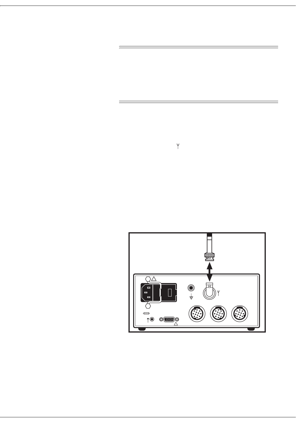
3. Insert the receiver antenna (longer of the two antennas) into the rear
panel Antenna connector ; rotate the attachment collar in a
clockwise direction until snug.
127(A Remote Antenna Bracket, cat. no. (REF) 1441AAO, is
available for attaching the antenna when the receiver will be
enclosed in a cart or cabinet. Refer to the Installation
Instructions, part no. (REF) 14153AA, included with the
bracket; or contact your Biomedical Engineering Department
for assistance. To attach the antenna to the BNC connector
on the bracket, rotate the antenna attachment collar in a
clockwise direction until snug.
Figure 4-6. Attaching the Receiver Antenna
ANTENNA
OUTPUTS TO MONITOR
CONNECT TO
COROMETRICS
MONITORS ONLY
ULTRASOUND ECG UA
!
WARNING: TO REDUCE FIRE HAZARD
REPLACE FUSE AS MARKED.
CAUTION
!
120Vac
~
120V ~ 50-60HZ 30W
0.25A SLOW BLOW
4-6 Model 340 Telemetry System Revision A
2006899-001
Setup Procedures: Connecting the Receiver and Monitor
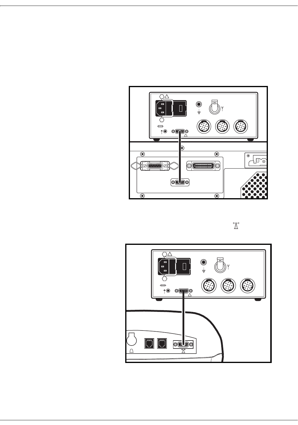
4. Plug one end of the interconnection cable into the Auxiliary Output
connector (Connect to Corometrics Monitor Only) on the receiver rear
panel.
5. Plug the other end into the respective telemetry connector on the
rear panel of the monitor:
120 Series: Connect to J101.
Figure 4-7. Attaching the Monitor Interconnect Cable to a 120 Series Monitor
170 Series: Connect to the receptacle labeled .
Figure 4-8. Attaching the Monitor Interconnect Cable to a 170 Series Monitor
CAUTION: FEDERAL
LAW RESTRICTS
THIS
DEVICE TO SALE BY
OR ON THE ORDER
OF
A PHYSICIAN.
LEG P
L
TESTE
R
CONNECT TO
COROMETRICS
DATA ENTRY SYSTEMS
ONLY
CONNECT TO
COROMETRICS
SERIES 400 MONITORS
ONLY
CONNECT TO COROMETRICS
TELEMETRY RECEIVERS
ONLY
J10
2
J10
3
J10
1
ANTENNA
OUTPUTS TO MONITOR
CONNECT TO
COROMETRICS
MONITORS ONLY
ULTRASOUND ECG UA
!
WARNING: TO REDUCE FIRE HAZARD
REPLACE FUSE AS MARKED.
CAUTION
!
120Vac
~
120V ~ 50-60HZ 30W
0.25A SLOW BLOW
PUSH
RS232
1
RS232
2
ANTENNA
OUTPUTS TO MONITOR
CONNECT TO
COROMETRICS
MONITORS ONLY
ULTRASOUND ECG UA
!
WARNING: TO REDUCE FIRE HAZARD
REPLACE FUSE AS MARKED.
CAUTION
!
120Vac
~
120V ~ 50-60HZ 30W
0.25A SLOW BLOW
Revision A Model 340 Telemetry System 4-7
2006899-001
Setup Procedures: Setting Up the Transmitter
Setting Up the Transmitter
Installing Batteries
127(If the transmitter will not
be used for an extended period of
time, remove the batteries to
prevent damage due to battery
leakage.
1. Turn off the transmitter.
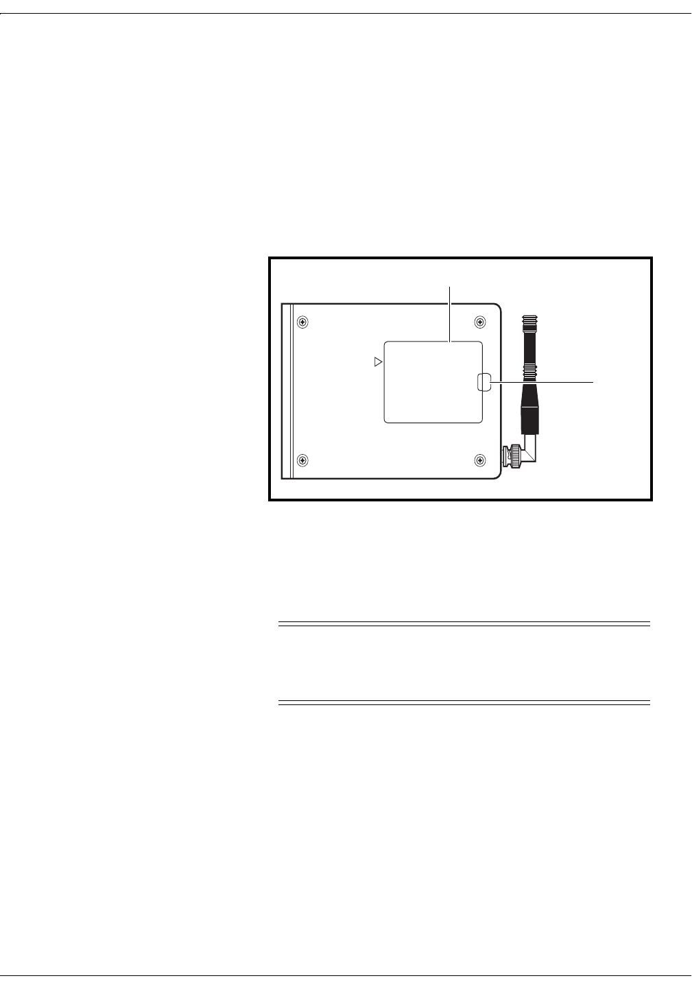
2. Locate the battery compartment cover plate on the transmitter rear
panel.
3. Remove the cover plate. Use your thumb to lift the raised end.
Figure 4-9. Accessing the Batteries
4. Remove the depleted batteries.
&$87,21
BATTERY DISPOSAL—Follow the battery
manufacturer’s recommendations or your hospital policy
for the disposal of used batteries.
DANGER: POSSIBLE EXPLOSION HAZARD IF USED
IN THE PRESENCE OF FLAMMABLE ANESTHETICS.
CAUTION: REFER SERVICE ONLY TO QUALIFIED PERSONNEL
!
BATTERY COMPARTMENT
Battery Compartment
Lift
Here
4-8 Model 340 Telemetry System Revision A
2006899-001
Setup Procedures: Setting Up the Transmitter
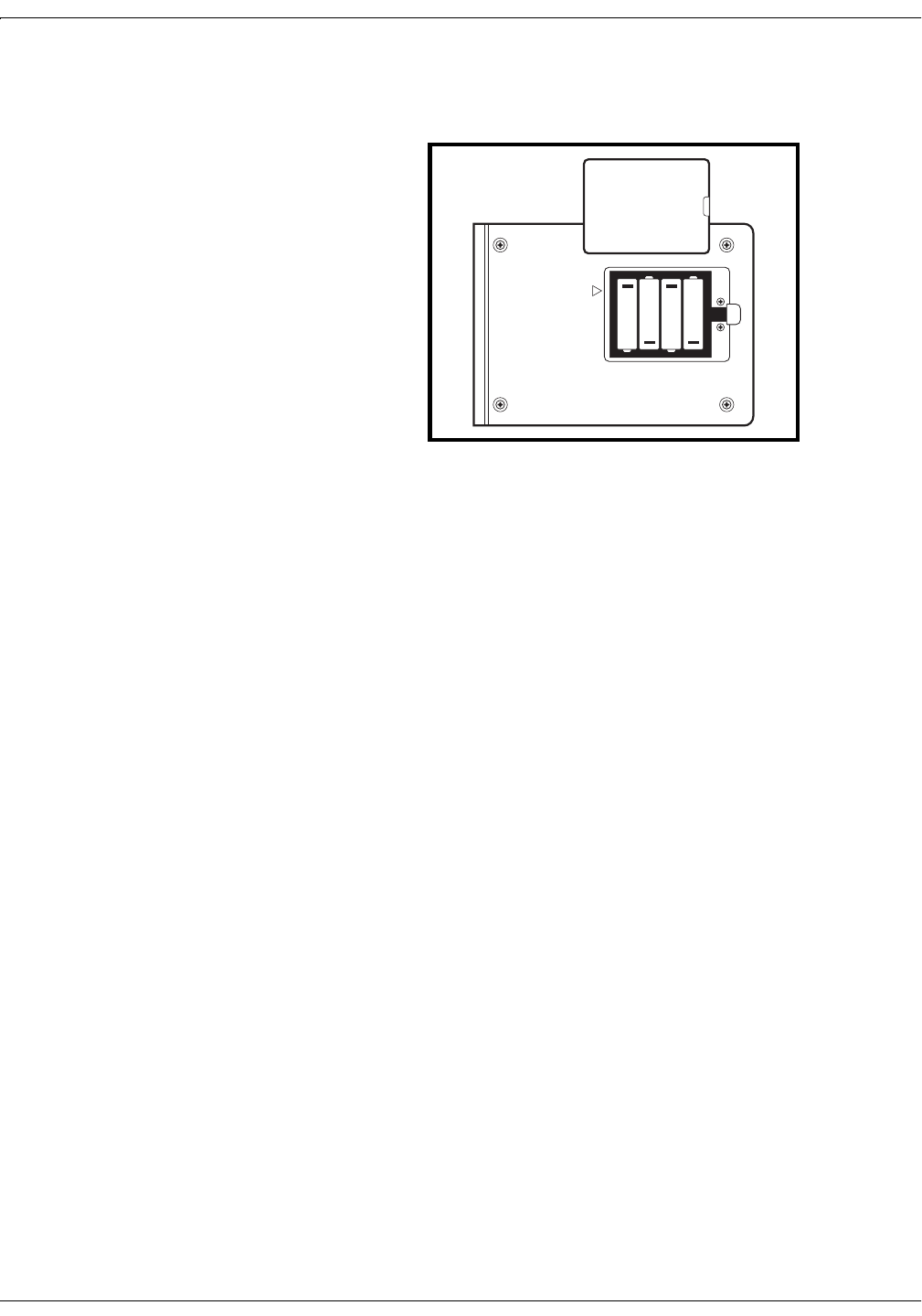
5. Insert four new “AA” alkaline batteries, observing the polarity
markings in the battery compartment.
Note: Antenna shown removed
Figure 4-10. Transmitter Battery Orientation
6. Replace the battery compartment cover plate. Insert the lip of the
cover in the lower portion of the compartment opening; swing the
other end of the cover down and snap into place.
BATTERY COMPARTMENT
!
DANGER: POSSIBLE EXPLOSION HAZARD IF USED
IN THE PRESENCE OF FLAMMABLE ANESTHETICS.
CAUTION: REFER SERVICE ONLY TO QUALIFIED PERSONNEL
+
+
+
+
Revision A Model 340 Telemetry System 4-9
2006899-001
Setup Procedures: Setting Up the Transmitter
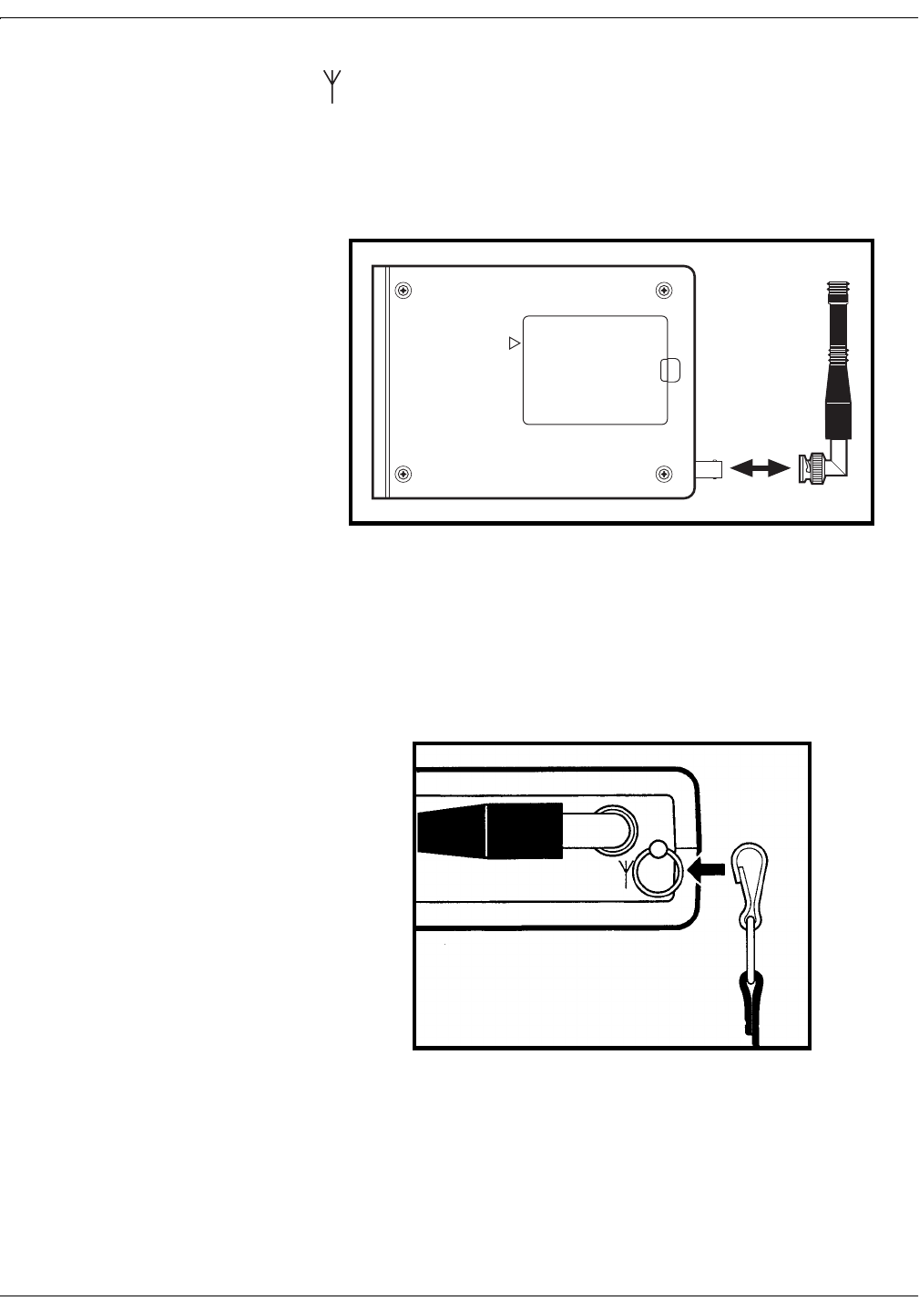
Attaching the Antenna
Insert the transmitter antenna (shorter of the two antennas) into the top
panel Antenna connector; rotate the attachment collar in a clockwise
direction until snug.
Figure 4-11. Attaching the Transmitter Antenna
Attaching the Carrying Strap
Secure the metal clips at each end of the carrying strap to the belt
attachment loops on each side of the transmitter.
Figure 4-12. Attaching the Carrying Strap
DANGER: POSSIBLE EXPLOSION HAZARD IF USED
IN THE PRESENCE OF FLAMMABLE ANESTHETICS.
CAUTION: REFER SERVICE ONLY TO QUALIFIED PERSONNEL
!
BATTERY COMPARTMENT
4-10 Model 340 Telemetry System Revision A
2006899-001
Setup Procedures: Performing a Functional Checkout
Performing a Functional Checkout
Initial Conditions
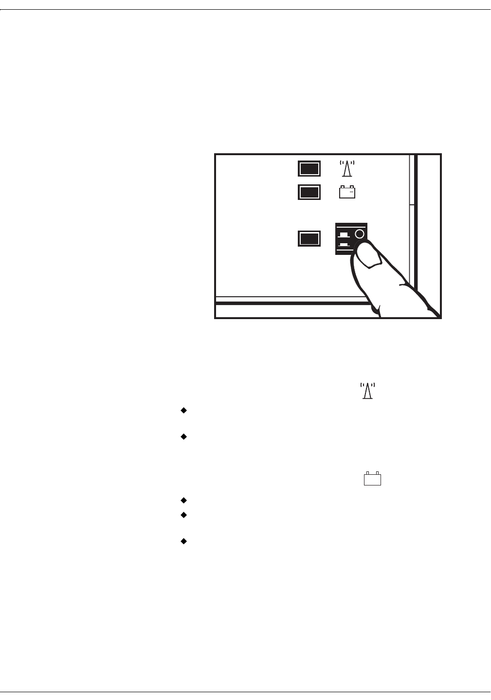
Turn on the transmitter, the receiver, and the monitor attached to the
receiver.
Figure 4-13. Applying Power
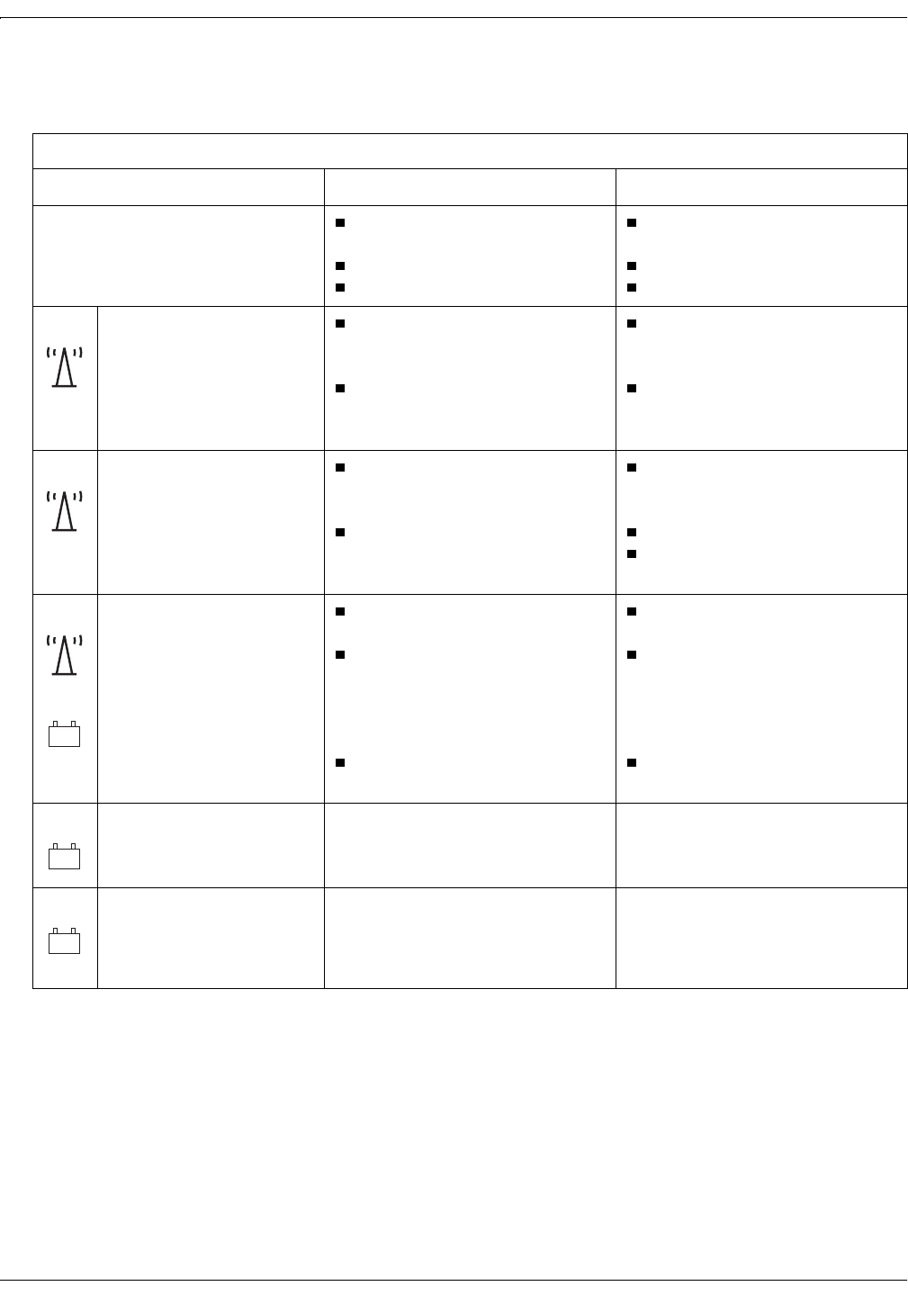
Testing the Radio Frequency
1. Check the status of the Signal indicator on the receiver:
Continuous Green: indicates the transmitter is active and the
batteries have adequate capacity.
Flashing Green: indicates the signal strength is weak or
marginal.
2. Check the status of the Battery indicator on the receiver:
Off: the transmitter batteries have power.
Flashing Red: the transmitter batteries are low and should be
replaced before further patient use.
Continuous Red: the transmitter batteries are depleted.
+
+
Revision A Model 340 Telemetry System 4-11
2006899-001
Setup Procedures: Performing a Functional Checkout
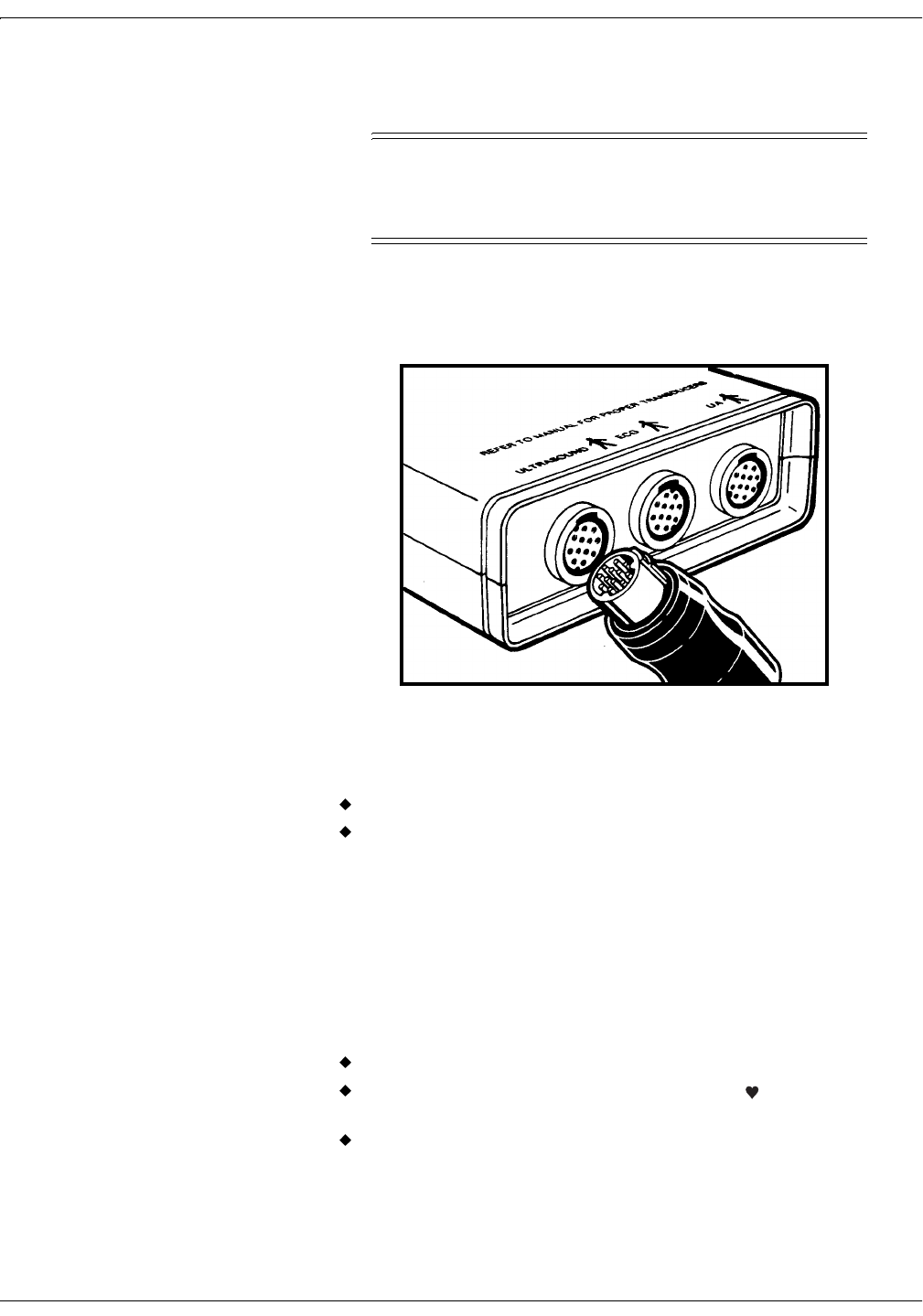
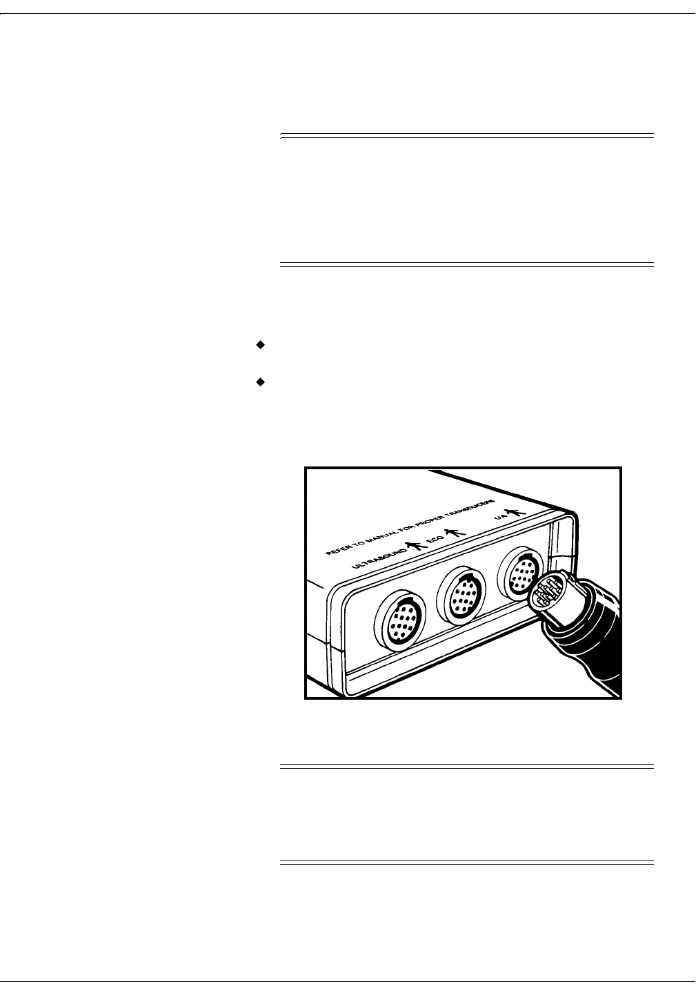
Testing the Ultrasound Functions
,03257$17
TRANSDUCER TYPE—Use only Corometrics 5700
Series Ultrasound Transducers with the Model 340
Telemetry System.
1. Plug an ultrasound transducer into the Ultrasound connector on the
transmitter.
Figure 4-14. Connecting an Ultrasound Transducer
2. Verify the following:
Models 115, 145: The corresponding FHR display reads 0 BPM.
Models 116, 118, 150, 151, 118, 155 and Series 120, 170: The
corresponding FHR display shows “– – –”.
If the display fails to illuminate, ensure that the corresponding
interconnection cable is firmly attached to both the monitor and the
receiver.
3. Use your finger to gently rub the ultrasound transducer face in a
rhythmic manner—to simulate a FHR. Try to maintain a steady rate
and verify the following on the monitor:
the corresponding FHR display value responds to the rubbing;
the corresponding FHR heartbeat indicator responds to the
input; and
the ultrasound audio tones are synchronous with the transducer
stroking.
4-12 Model 340 Telemetry System Revision A
2006899-001
Setup Procedures: Performing a Functional Checkout
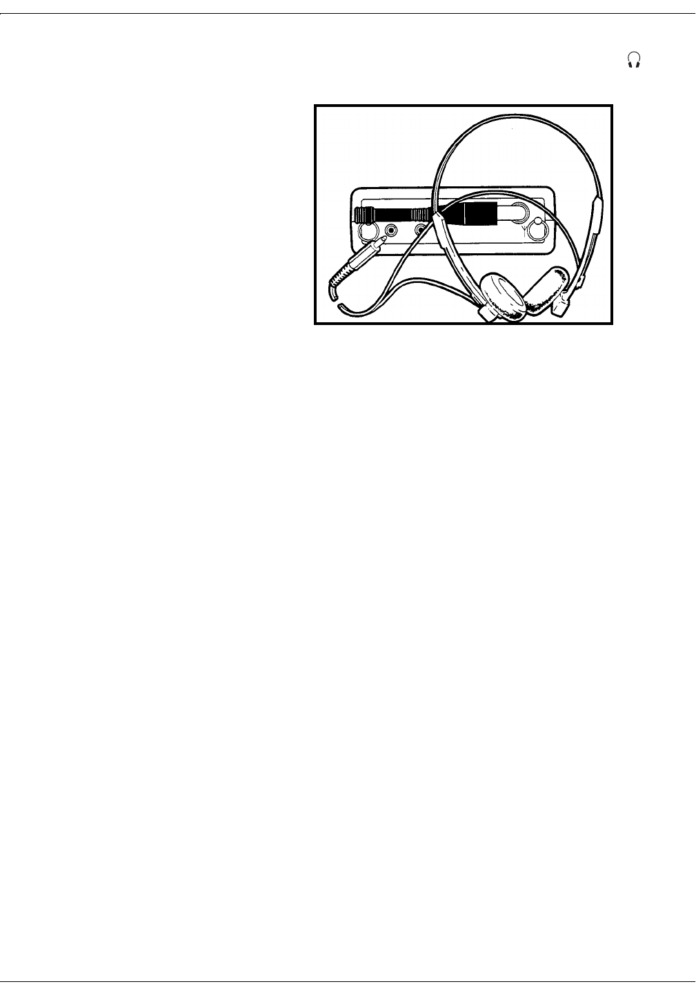
4. Plug the headset into the transmitter’s headset connector .
Figure 4-15. Connecting the Headset
5. Rub the face of the ultrasound transducer. Verify that you can hear
ultrasound audio tones from both sides of the headset.
Revision A Model 340 Telemetry System 4-13
2006899-001
Setup Procedures: Performing a Functional Checkout
Testing the ECG Functions
127(Not all monitors have a
legplate tester. Refer to your
monitor’s operator’s manual for
complete information.
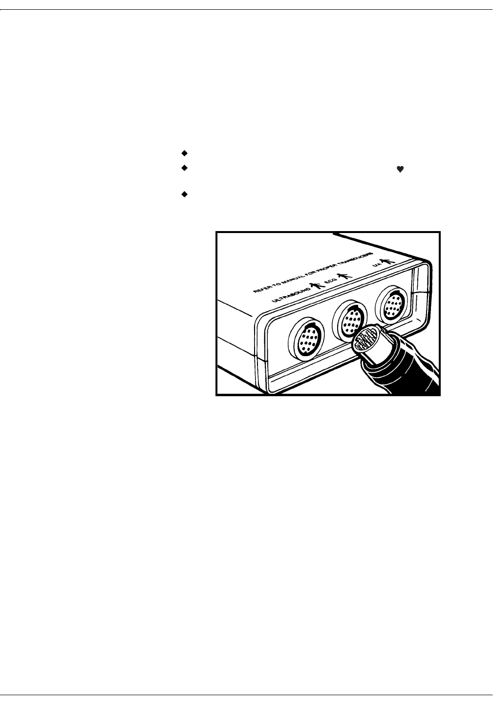
1. Slide the legplate into the monitor’s Legplate Tester jack and hold
firmly in place. (The legplate tester uses an internal ECG simulator
circuit for testing cable/legplate assemblies. The tester simulates a
signal of 120 BPM ± 1 BPM.)
2. Plug the other end into the ECG connector on the transmitter. Verify
the following on the monitor:
the corresponding FHR value reads 120 BPM;
the corresponding FHR heartbeat indicator flashes at a rate of
120 times per minute; and
the ECG “beep” is heard from the speaker.
Figure 4-16. Connecting an FECG Cable/Legplate
4-14 Model 340 Telemetry System Revision A
2006899-001
Setup Procedures: Performing a Functional Checkout
Testing the UA Functions
1. Place the receiver’s UA Mode Selector switch in the TOCO position.
,03257$17
TRIMLINE TOCOTRANSDUCERS—If the monitor is on
when you connect or re-connect a Trimline
Tocotransducer to the UA connector, you must wait at
least 10 seconds before pressing the UA Reference button.
If the monitor is off, you must wait at least 10 seconds
from the time the monitor is powered on.
2. Plug a tocotransducer into the transmitter’s UA connector. Verify the
following on the monitor:
If the monitor has a UA display: the display reads an arbitrary
pressure value.
If the monitor does not have a UA display: turn on the strip chart
recorder and check that TOCO prints on the paper’s mode
annotation line.
Figure 4-17. Connecting a Tocotransducer or IUPC Cable
,03257$17
DEFAULT REFERENCE VALUE—Most monitors have
a default UA reference of 10 relative units. Take into
consideration that newer model monitor’s can be
configured to store a custom default value.

Revision A Model 340 Telemetry System 4-15
2006899-001
Setup Procedures: Performing a Functional Checkout
3. Press the monitor’s UA Reference button to set the UA value to 10
relative units. Verify the following on the monitor:
If the monitor has a UA display: the display reads 10 relative
units.
If the monitor does not have a UA display: turn on the strip chart
recorder and check that the UA REF message and TOCO mode
annotation both print on the paper.
4. Apply gentle pressure to the tocotransducer pressure sensing button
and verify that the monitor (display or uterine activity trace)
responds to the pressure input. Increasing force should produce an
increasing value and vice versa.
If no pressure changes are recorded, ensure that the corresponding
interconnection cable is firmly attached to both the monitor and the
receiver.
5. This step applies to monitors which support IUP monitoring. Place
the receiver’s UA Mode Selector switch in the IUP position. Verify the
following on the monitor:
If the monitor has a mode indicator: the IUP mode should be
indicated.
If the monitor does not have a mode indicator: turn on the strip
chart recorder and check that the IUP mode annotation prints on
the paper.
127(Place the UA Mode Selector switch back in the TOCO position
unless you plan to monitor with an IUPC.

4-16 Model 340 Telemetry System Revision A
2006899-001
Setup Procedures: Performing a Functional Checkout
Testing the Remote Event Marker Function
1. Plug the Remote Event Marker into the transmitter’s Remote Marks
connector.
2. Turn on the monitor’s strip chart recorder.
3. Press the Remote Event Marker’s pushbutton for at least one second.
Verify that an appropriate mark is printed on the paper:
: This annotation is commonly used to record an “event.” This
mark is available on all Corometrics-brand monitors.
: This annotation is commonly used as an indication that the
mother has perceived fetal movement. (Refer to your monitor’s
operator’s manual to learn if your monitor supports this feature.
Refer to your monitor’s service manual for information about
enabling the option.)
Testing the Environment
Decide on which areas of your facility will be used for ambulatory
monitoring. Test each location separately to rule out rooms that are
restricted due to metal structures blocking signal transmission.
F
M

Revision A Model 340 Telemetry System 5-1
2006899-001
Chapter 5
Monitoring via Telemetry5
This section provides a brief overview of telemetry monitoring
procedures. Refer to the "Maternal/Fetal Monitoring Operator’s Manual"
for patient application information. Also refer to your monitor’s
operator’s manual.
Suggestions for Ambulatory Monitoring. . . . . . . . . . . . . . . . 5-2
Monitoring Reminders. . . . . . . . . . . . . . . . . . . . . . . . . . . . . . 5-3

5-2 Model 340 Telemetry System Revision A
2006899-001
Monitoring via Telemetry: Suggestions for Ambulatory Monitoring
Suggestions for Ambulatory Monitoring
,03257$17
DESIGNATED AREAS—Show the patient the areas that
are within signal range and where signal reception is
clear.
1. Instruct the patient to wear the transmitter with the antenna
pointed towards the receiver when possible.
2. Adjust the carrying strap to a comfortable length.
3. Encourage the patient to walk in a smooth, gliding motion. It is
preferable to slide feet rather than moving quickly which may cause
bouncing and artifact.
4. Instruct the patient, following each fetal movement, to listen via the
headset, for continued fetal heart rate tones.
127(Transducers with short
cables are available. Contact your
Information Technologies Sales
Representative.
5. Make sure the transducer cables are not dragging on the floor. If the
patient is in danger of tripping over the cables, drape them over the
patient’s arm; or shorten the length by taping a loop.

Revision A Model 340 Telemetry System 5-3
2006899-001
Monitoring via Telemetry: Monitoring Reminders
Monitoring Reminders
General
Use the correct interconnection method according to your monitor
model. See page 4-2 and page 4-5.
Remember to apply power to all three devices: monitor, receiver, and
transmitter.
Check that each interconnection cable is firmly attached to both the
receiver and the monitor.
As soon as any telemetry mode is detected, the front panel of the 120
or 170 Series Monitor is disabled and all front panel inputs are
ignored. In other words, telemetry and monitor modes cannot be
“mixed and matched”; you must use telemetry only or direct
monitoring only.
,03257$17
170 SERIES—For proper operation with a 170 Series
Monitor, disconnect all transducers from the front panel
of the monitor.
Ultrasound
Use only Corometrics 5700 Series ultrasound transducers with a
Model 340 Telemetry System.
Remind the patient to use the headset to check for continual pickup
of the fetal heart rate signal following each fetal movement.
FECG
You may need to tape the transducer cable to the patient to prevent
excessive tension on the legplate or attachment pad.
The recommended position for the legplate is on top of the upper
thigh instead of the inner thigh. This facilitates walking and
minimizes fluid contacting the legplate.

5-4 Model 340 Telemetry System Revision A
2006899-001
Monitoring via Telemetry: Monitoring Reminders
Tocotransducer
Remember to place the receiver’s UA Mode Selector switch in the
TOCO position.
When connecting or re-connecting a Corometrics Trimline
Tocotransducer to the transmitter’s UA connector, you must wait at
least 10 seconds before pressing the monitor’s UA Reference button. If
any device (monitor, receiver, transmitter) is off, you must wait at
least ten seconds from the time the last device is powered on.
IUP
Remember to place the receiver’s UA Mode Selector switch in the IUP
position.

Revision A Model 340 Telemetry System 6-1
2006899-001
Chapter 6
Maintenance 6
All equipment, no matter how reliable, needs to be maintained on a
regular basis. This section describes general care and cleaning
instructions for the Model 340 Telemetry System.
General Cleaning Precautions. . . . . . . . . . . . . . . . . . . . . . . . 6-2
Cleaning the Transmitter and Receiver . . . . . . . . . . . . . . . . 6-3

6-2 Model 340 Telemetry System Revision A
2006899-001
Maintenance: General Cleaning Precautions
General Cleaning Precautions
127(Refer to your monitor’s
operator’s manual for cleaning
instructions for the monitor and
transducers.
&$87,21
SHOCK—Unplug the fetal or maternal/fetal monitor and
the receiver from the AC power source and detach all
accessories. Do not immerse accessories in any liquid. Do
not use abrasive cloth or cleaners on the monitor, the
receiver, the transmitter, or any accessories.

Revision A Model 340 Telemetry System 6-3
2006899-001
Maintenance: Cleaning the Transmitter and Receiver
Cleaning the Transmitter and Receiver
1. Wipe any fluids from the surface of each unit.
2. Dampen a soft cloth with isopropyl alcohol and gently rub soiled area
until clean.
3. Dry with a soft, dry cloth.

6-4 Model 340 Telemetry System Revision A
2006899-001
For your notes

Revision A Model 340 Telemetry System 7-1
2006899-001
Chapter 7
Troubleshooting 7
This section of the manual provides a troubleshooting guide for the most
basic Model 340 operational problems. If the response to a specific
question is not found, contact the Service Department at one of the
following telephone numbers:
Inside the United States: Call 1-800-558-5120.
Outside the United States: Call 414-355-3790;
or contact your local distributor.
7-2 Model 340 Telemetry System Revision A
2006899-001
Troubleshooting: Problem Chart
Problem Chart
Table 7-1. Troubleshooting
Problem Probable Cause Solution
Receiver Power indicator does not light
when the receiver is turned on.
Receiver not connected to AC
receptacle.
Defective AC power cord.
Defective AC outlet.
Connect to AC receptacle.
Replace AC power cord.
Use a different AC outlet.
Signal indicator flashes with
transmitter turned on.
Transmitter batteries completely
discharged.
Mismatched transmitter and receiver
channels.
Replace batteries. Dispose of used
batteries according to the
manufacturer’s directions.
Ensure transmitter and receiver are
labeled with identical channel
numbers.
Signal indicator flashes
intermittently as patient
ambulates.
Patient outside signal transmission
range.
Metal in walls, doors, or other
structures between transmitter and
receiver.
Instruct patient to stay within signal
range and designated areas where
reception is clear.
Install optional ceiling antenna system.
Contact your Information Technologies
Service Representative.
Signal and Low Battery
indicators light with transmitter
turned off.
External source of radio frequency
interference is present.
Another transmitter with the same
frequency is in use within the same
facility.
Service required.
Contact your Information Technologies
Service Representative.
Discontinue use of one of the
transmitters. NOTE: Model 340 Plus
and Model 340M Telemetry Systems
can be factory re-programmed to an
alternative channel number.
Contact your Information Technologies
Service Representative.
Low Battery indicator flashes
with transducers plugged into
transmitter.
Transmitter batteries have less than 10
minutes of energy left.
Replace the batteries. Dispose of used
batteries according to the manufacturer’s
instructions.
Low Battery indicator lights
continuously with no
transducers plugged into
transmitter.
Transmitter batteries are depleted. Replace the batteries. Dispose of used
batteries according to the manufacturer’s
instructions.
+
+
+

Revision A Model 340 Telemetry System 7-3
2006899-001
Troubleshooting: Problem Chart
Erratic FHR/UA recording.
Transducer not properly placed.
Transducer not properly connected to
transmitter.
Receiver interconnection cable(s) not
properly attached.
Receiver interconnection cable(s)
defective.
Wrong interconnection cable(s) in use.
Radio frequency interference.
Another transmitter with the same
frequency is in use within the same
facility.
Exceeding transmission range.
Shielding effect of hospital structure.
Reposition transducer.
Ensure the transducer is securely
attached to the transmitter.
Ensure interconnection cable(s) firmly
attached to both monitor and receiver.
Replace interconnection cable(s).
Verify interconnection method.
Instruct patient to stay within signal
range and designated areas where
reception is clear.
Discontinue use of one of the
transmitters. NOTE: Model 340 Plus
and Model 340M Telemetry Systems
can be factory re-programmed to an
alternative channel number.
Install optional ceiling antenna system.
Contact your Information Technologies
Service Representative.
Monitor FHR and UA displays do not light
when transducers are plugged into
transmitter.
Monitor, transmitter, and/or receiver
off.
Receiver interconnection cable(s) not
properly attached.
Receiver interconnection cable(s)
defective.
Wrong interconnection cable(s) in use.
Ensure all three devices are turned on.
Ensure interconnection cable(s) firmly
attached to both monitor and receiver.
Replace interconnection cable(s).
Verify interconnection method.
Transmitter “chirps” every 4–5 seconds. Transmitter batteries have less than 10
minutes of energy left.
Replace the batteries. Dispose of used
batteries according to the manufacturer’s
instructions.
Table 7-1. Troubleshooting (Continued)
Problem Probable Cause Solution

7-4 Model 340 Telemetry System Revision A
2006899-001
For your notes

Revision A Model 340 Telemetry System 8-1
2006899-001
Chapter 8
Supplies and
Accessories 8
This section provides an overall listing of supplies and accessories for use
with a Corometrics Model 340 Telemetry System and with Corometrics
Fetal or Maternal/Fetal Monitors. To order any of the supplies and
accessories listed in this manual:
Inside the United States: Call 1-800-558-5120.
Outside the United States: Call 414-355-3790;
or contact your local distributor.
This chapter contains the following information:
General . . . . . . . . . . . . . . . . . . . . . . . . . . . . . . . . . . . . . . . . . . 8-2
Paper. . . . . . . . . . . . . . . . . . . . . . . . . . . . . . . . . . . . . . . . . . . . 8-3
Ultrasound . . . . . . . . . . . . . . . . . . . . . . . . . . . . . . . . . . . . . . . 8-4
FECG . . . . . . . . . . . . . . . . . . . . . . . . . . . . . . . . . . . . . . . . . . . 8-5
Tocotransducer. . . . . . . . . . . . . . . . . . . . . . . . . . . . . . . . . . . . 8-6
IUPC . . . . . . . . . . . . . . . . . . . . . . . . . . . . . . . . . . . . . . . . . . . . 8-7
MECG . . . . . . . . . . . . . . . . . . . . . . . . . . . . . . . . . . . . . . . . . . . 8-8

8-2 Model 340 Telemetry System Revision A
2006899-001
Supplies and Accessories: General
General
Table 8-1. General Supplies
Item Catalog Number (REF)
Detachable IEC AC Power Cord, United States Plug 1392AAA
Remote Event Marker, 8-foot Cord 3919BAO
Remote Event Marker, 5-foot Cord 3919CAO
Headset for Model 340 Telemetry System 3316AAO
Ultrasound Interconnect Cable (Models 115, 145 only) 1399AAO
Ultrasound Interconnect Cable (Models 116, 118, 150, 151, 155 only) 1399BAO
ECG Interconnect Cable (Models 115, 116, 118, 145, 150, 151, 155 only) 1375BAO
UA Interconnect Cable (Models 115, 116, 118, 145, 150, 151, 155 only) 1400AAO
Mark Interconnect Cable (Models 115, 116, 118, 145, 150, 151, 155 only) 1397AAO
System Interconnect Cable (Series 120, 170 only) 1563AAO
Remote Antenna Bracket with Extension Cable for Cart Use 1441AAO
Model 2116B Clinical-Notes/Data-Entry System 2116BAX
Model 3116 LDR/LDRP Bonnet Style Mobile Cart—Finished 3116AAO
Model 3116 LDR/LDRP Bonnet Style Mobile Cart—Unfinished 3116BAO
Model 3116 LDR/LDRP Bonnet Style Mobile Cart with Hinged Drawer Front—Unfinished 3116DAO
Model 3116 LDR/LDRP Bonnet Style Mobile Cart with Hinged Drawer Front—Finished 3116EAO
Model 146 Fetal Acoustic Stimulator 0146AAY

Revision A Model 340 Telemetry System 8-3
2006899-001
Supplies and Accessories: Paper
Paper
Table 8-2. Paper Supplies
Item Catalog Number (REF)
Z-Fold Chart Paper Pack, 30–240 BPM Heart Rate Scale (40/carton) 4305CAO
Z-Fold Chart Paper Pack, 50–210 BPM Heart Rate Scale (40/carton) 4305DAO
Chart Guard Label Packet 4914BAO

8-4 Model 340 Telemetry System Revision A
2006899-001
Supplies and Accessories: Ultrasound
Ultrasound
,03257$17
TRANSDUCER TYPE—Use only Corometrics 5700
Series Ultrasound Transducers. Do not use a Corometrics
5600 Series Transducer. The 5600 Series Transducers
are only for direct connection to a Model 115 or Model 145
Fetal Monitor or for use with a Model 320 or Model 330
Telemetry System.
Table 8-3. Ultrasound Supplies
Item Catalog Number (REF)
Loop-Style Ultrasound Transducer, 5-foot Cord 5700EAX
Loop-Style Ultrasound Transducer, 8-foot Cord 5700AAX
Loop-Style Ultrasound Transducer, 10-foot Cord 5700CAX
Button-Style Ultrasound Transducer, 5-foot Cord 5700FAX
Button-Style Ultrasound Transducer, 8-foot Cord 5700BAX
Loop-Style Ultrasound Transducer (Nautilus), 5-foot Cord 5700KAX
Loop-Style Ultrasound Transducer (Nautilus, 8-foot Cord 5700LAX
Loop-Style Ultrasound Transducer (Nautilus), 10-foot Cord 5700MAX
Button-Style Ultrasound Transducer (Nautilus), 5-foot Cord 5700GAX
Button-Style Ultrasound Transducer (Nautilus), 8-foot Cord 5700HAX
Loop-Style Ultrasound Transducer (Nautilus), 5-foot Cord 5700JAX
Ultrasound Coupling Gel Bottle, 250 ml (12/carton) 2434AAO
Ultrasound Coupling Gel Bottle, 5 liter 2475AAO
Reusable Belt for Loop-Style Transducer, Mesh Style (10/carton) 4425AAO
Reusable Belt for Loop-Style Transducer, Velcro Style (10/carton) 4425CAO
Reusable Belt for Button-Style Transducer, Elastic Style (10/carton) 4425EAO
Semi-Reusable Belt for Loop-Style Transducer, Velcro Style
(2/pack; 50 packs/carton) 4425FAO
Single-Patient Use Belt for Loop-Style Transducer,
Foam Style with Velcro Closure 8024AAO

Revision A Model 340 Telemetry System 8-5
2006899-001
Supplies and Accessories: FECG
FECG
Table 8-4. FECG Supplies
Item Catalog Number (REF)
Qwik Connect Plus Spiral Electrode (50/carton) 7000AAO
Legplate for Qwik Connect Plus Spiral Electrode, 8-foot Cord 1590AAO
Strap Adaptor for Qwik Connect Plus Spiral Electrode Legplates 1594AAO
ECG Conductive Cream Bottle, 118 ml (12/carton) 4514AAO
Reusable Legplate Strap with Velcro Closure (24/carton) 2023AAO
Single-Patient Use Legplate Strap 8036AAO

8-6 Model 340 Telemetry System Revision A
2006899-001
Supplies and Accessories: Tocotransducer
Tocotransducer
Table 8-5. Tocotransducer Supplies
Item Catalog Number (REF)
Loop-Style Tocotransducer (Nautilus), 5-foot Cord 2264KAX
Loop-Style Tocotransducer (Nautilus), 8-foot Cord 2264LAX
Loop-Style Tocotransducer (Nautilus), 10-foot Cord 2264MAX
Button-Style Tocotransducer (Nautilus), 5-foot Cord 2264GAX
Button-Style Tocotransducer (Nautilus), 8-foot Cord 2264HAX
Button-Style Tocotransducer (Nautilus), 10-foot Cord 2264JAX
Reusable Belt for Loop-Style Transducer, Mesh Style (10/carton) 4425AAO
Reusable Belt for Loop-Style Transducer, Velcro Style (10/carton) 4425CAO
Reusable Belt for Button-Style Transducer, Elastic Style (10/carton) 4425EAO
Semi-Reusable Belt for Loop-Style Transducer, Velcro Style
(2/pack; 50 packs/carton) 4425FAO
Single-Patient Use Belt for Loop-Style Transducer,
Foam Style with Velcro Closure 8024AAO

Revision A Model 340 Telemetry System 8-7
2006899-001
Supplies and Accessories: IUPC
IUPC
Table 8-6. IUPC Supplies
Item Catalog Number (REF)
Corometrics Softrans IUPC with Amnio Infusion/Sampling
Capabilities (10/carton) 2076AAO
Corometrics Softrans Intermediate Cable 1336AAO
Reusable Strain Gauge Pressure Transducer, 10-foot Cord
(with Holder) 4007BAX
Reusable Strain Gauge Pressure Transducer, 10-foot Cord
(without Holder) 4007LAX
Holder for Reusable Pressure Transducer 4516BAO
IUP Kit with Syringe for Reusable Pressure Transducer (50/carton) 2069AAO
Single-Patient Use Sterile Dome (10/carton) 5512AAO
Single-Patient Use Sterile Dome (120/carton) 5512BAO
Reusable Dome (5/carton) 5507AAO
Pressure Relief Valve for Pressure Transducer Dome (5/carton) 8070AAO
Disposable Strain Gauge Pressure Transducer (10/carton) 4009AAX
Holder for Disposable Pressure Transducer 4519AAO
Holder Assembly for Disposable Pressure Transducer 4518BAO

8-8 Model 340 Telemetry System Revision A
2006899-001
Supplies and Accessories: MECG
MECG
Table 8-7. MECG Supplies
Item Catalog Number (REF)
MECG Cable (round connector) for use with detachable leadwires, USA/AHA 1554AAO
MECG Cable (round connector) for use with detachable leadwires, Intl./IEC 1554BAO
Multi-Link Snap Leadwires, Set of 3, Grouped Detachable, 31 inches 411203-001
Multi-Link Snap Leadwires, Set of 5, Individually Detachable, 31 inches 411200-001
Multi-Link Grabber Leadwires, Set of 3, Grouped Detachable, 31 inches 412682-001
Multi-Link Grabber Leadwires, Set of 5, Individually Detachable, 31 inches 414556-001
Leadwire Adapter, 3-Lead Multi-Link to 3-Lead DIN 414371-001
Electrodes, Round, Foam, Pouches of 30, Case of 300 9431-004

Revision A Model 340 Telemetry System 9-1
2006899-001
Chapter 9
Technical
Specifications 9
127(Specifications are subject
to change without notice. This section contains a detailed list of the technical specifications for the
Model 340 Telemetry System.
This chapter lists specifications for the following:
Transmitter . . . . . . . . . . . . . . . . . . . . . . . . . . . . . . . . . . . . . . 9-2
Receiver. . . . . . . . . . . . . . . . . . . . . . . . . . . . . . . . . . . . . . . . . . 9-4

9-2 Model 340 Telemetry System Revision A
2006899-001
Technical Specifications: Transmitter
Transmitter
Table 9-1. Transmitter
Category Technical Specifications
Physical Characteristics
Height:
Width:
Depth:
Weight:
1.8 in (4.5 cm)
5.4 in (13.8 cm)
7.5 in (19.0 cm)
1.75 lbs (0.8 kg)
Environmental Conditions
Ambient Temperature:
Relative Humidity:
Atmospheric Pressure:
Operating Storage
50°F to 104°F (10°C to 40°C) 14°F to 131°F (–10°C to 55°C)
5% to 95%, non-condensing 5% to 95%, non-condensing
700–1060 mbar (525–795 mmHg) 700–1060 mbar (525–795 mmHg)
Certification and Compliance
UL:
FCC:
Industry Canada:
340 Original Release and Plus 340M
UL-544 Listed UL-544 Listed
Complies with FCC Part 90 Complies with FCC Part 95
Complies with RSS-119 Complies with RSS-210
Monitoring Modes
Fetal Heart Rate:
Uterine Activity:
Maternal Heart Rate:
Ultrasound (US) and Fetal ECG (FECG)
External Tocotransducer (TOCO) or Internal Intrauterine Pressure Catheter (IUPC)
Maternal ECG (MECG)
Ultrasound Mode
System:
Transmitter Frequency:
Intensity (Isata):
Pulse Doppler
1.151 MHz
<5 mW/cm2
ECG Mode
Input Impedance:
dc Tolerance:
Common Mode Rejection Ratio:
FECG Sensitivity:
MECG Sensitivity:
>1 GΩ
±1 V
>90 dB
20 µV to 1 mV
0.5 mV to 5 mV
TOCO Mode
Type:
Sensitivity:
Range:
Tocotransducer
20 µV/relative unit
–50 to +250 relative units
IUPC Mode
Type:
Sensitivity:
Range:
dc Strain Gauge
20 µV/mmHg
–50 to +250 mmHg
RF Section
Output Power:
Available Frequencies:
Channel Bandwidth:
340 Original Release and Plus 340M
10 mW 4 mW
430–470 MHz 608–614 MHz
25 kHz 25 kHz
Transmission Range: 340 Original Release and Plus 340M
1640 ft (500 m), line of sight 200 ft (61 m), line of sight

Revision A Model 340 Telemetry System 9-3
2006899-001
Technical Specifications: Transmitter
Antenna Type: Flexible, detachable, BNC interconnect
Batteries
Type:
Life: Four “AA” Alkaline Cells, 6.0 Vdc at 2450 mAh
20 h, approximatelya
Control: On/Off Switch
Audio Indicator: Low Battery
Connectors: Remote Event Marker Input, Headset Output
aUse of the headset will deplete the batteries more rapidly.
Table 9-1. Transmitter
Category Technical Specifications

9-4 Model 340 Telemetry System Revision A
2006899-001
Technical Specifications: Receiver
Receiver
Table 9-1. Receiver
Category Technical Specifications
Power Requirements
Nominal Line Voltage:
Line Frequency:
Power Consumption (maximum):
Chassis Leakage:
100–120 VAC 220–240 VAC
50/60 Hz 50/60 Hz
30 W 30 W
<50 µA
Physical Characteristics
Height:
Width:
Depth:
Weight:
3.2 in (8.1 cm)
7.4 in (18.8 cm)
11.4 in (29.0 cm)
7.0 lbs (3.2 kg)
Environmental Conditions
Ambient Temperature:
Relative Humidity:
Atmospheric Pressure:
Operating Storage
50°F to 104°F (10°C to 40°C) 14°F to 131°F (–10°C to 55°C)
5% to 95%, non-condensing 5% to 95%, non-condensing
700–1060 mbar (525–795 mmHg) 700–1060 mbar (525–795 mmHg)
Certification and Compliance
UL:
FCC:
Industry Canada:
340 Original Release and Plus 340M
UL-544 Listed UL-544 Listed
Complies with FCC Part 15 Complies with FCC Part 15
Complies with RSS-119 Complies with RSS-210
Output Signals: US, ECG, UA, and Mark
RF Section
Input Impedance:
Input Sensitivity: 50 Ω
<0.4 µV for 12 dB SINAD
Antenna Type: Flexible, detachable, BNC interconnect
(Other factory-approved external antennas or antenna systems may be used. Contact
your Information Technologies Service Representative for more information.)
Controls: On/Off Switch, UA Mode Switch
Visual Indicators:
Power:
Signal Strength:
Transmitter Low/Depleted Battery:
Green LED
Green LED
Red LED
Connectors
AC Line Input:
Mark Output:
Ultrasound Output:
ECG Output:
UA Output:
Auxiliary Output:
3-Prong, IEC-Style
Use only with Models 115, 116, 118, 145, 150, 151, and 155 Monitors.
Use only with Models 115, 116, 118, 145, 150, 151, and 155 Monitors.
Use only with Models 115, 116, 118, 145, 150, 151, and 155 Monitors.
Use only with Models 115, 116, 118, 145, 150, 151, and 155 Monitors.
Use only with Series 120 and 170 Monitors.
MANUAL P/N 2006899-001 REV
A
Ê2006899-001~Š