GE Medical Systems Information Technologies 340MT WMTS Transmitter User Manual TRANSMITTER
GE Medical Systems Information Technologies Inc. WMTS Transmitter TRANSMITTER
Contents
Ex 13d 18921274
SR600 RECEIVER
OPERATING INSTRUCTIONS
These operating instructions are intended to provide the user with sufficient information to
install and operate the unit correctly.
The Wood and Douglas SR600 UHF synthesized receiver is intended to fulfil the numerous
OEM applications by virtue of its highly flexible synthesized design approach, miniature
size and cost-effective performance.
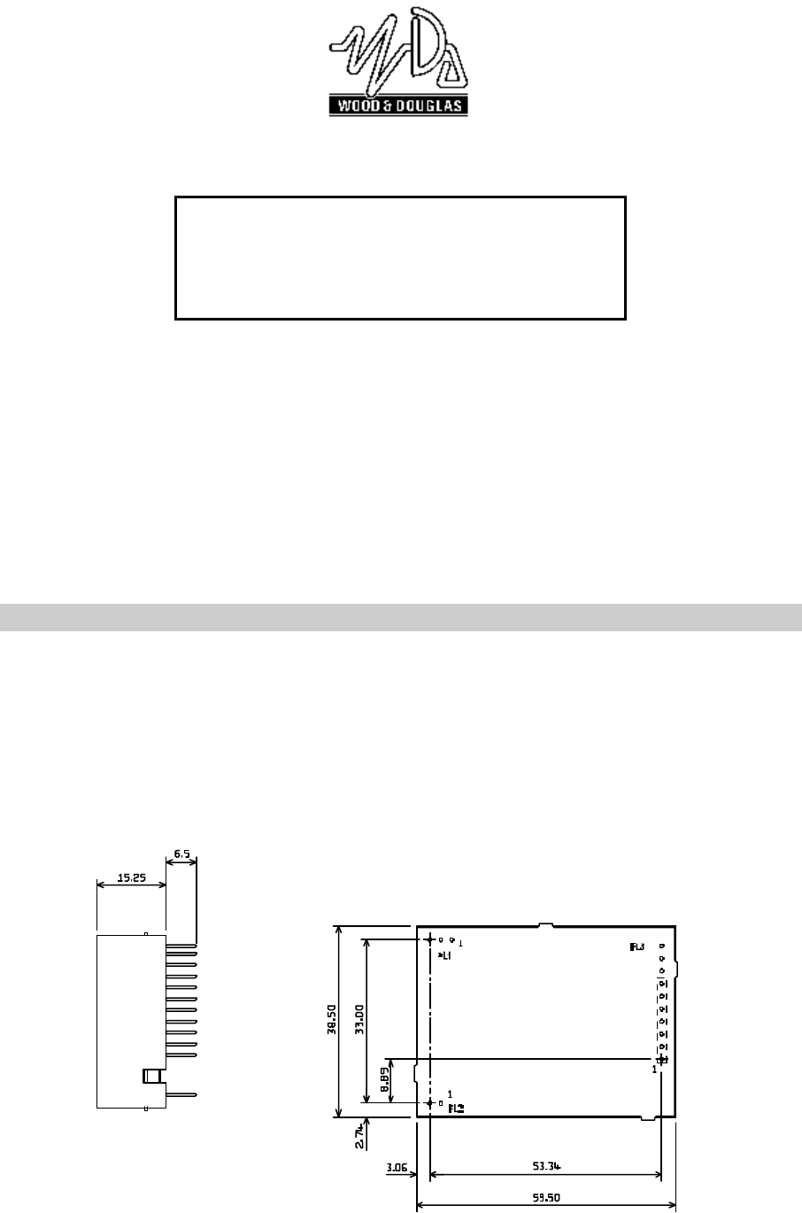
INSTALLATION
NOTES: Pin spacing on all connectors is 2.54mm (0.1")
All dimensions in millimetres
CONNECTION
Connection to the SR600 receiver is via PL1, PL2 and PL3 which plug directly into the
user's own equipment. The location of these connectors is shown in Figure 1 and detailed
in the following tables.
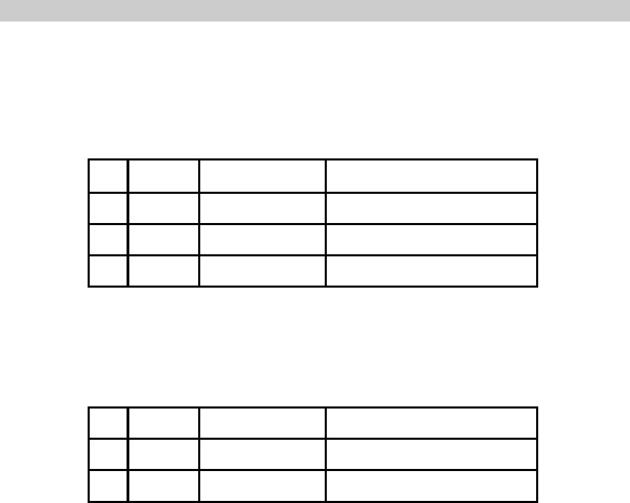
PIN NAME FUNCTION REMARKS
10V 0 volts common ground
2RF I/P RF input 50 ohms input
30V 0 volts common ground
Connector PL1 pin detail
PIN NAME FUNCTION REMARKS
1+VIN positive supply +6.0V to +15.0V
20V 0 volts common ground
Connector PL2 pin detail

PIN NAME FUNCTION REMARKS
1RSSI S meter output 0.5 - 2V signal strength indicator, 60dB range
2SQF Squelch flag open collector output, ON (low) = no signal
3AUDIO AF output
250mV p-p ±20% into 10kS
Note: The output audio is inverted with respect to
the ST600 (or similar Wood & Douglas product)
audio input.
4DATA Data output open collector, no pull-up
Note: The data output is inverted with respect to
the ST600 (or similar Wood & Douglas product)
data input.
5+5V +5 volt supply output 50mA maximum current drain
60V 0 volts common ground
7
RS232
I/P serial programming
input RS232 programming input
Note: inverted TTL level data can also be used. If
not used, leave not connected, or connect to 0/V
8RB1 parallel frequency
select internal pull-up to +5V, active low
9RB2
10 RB3
Connector PL3 pin detail
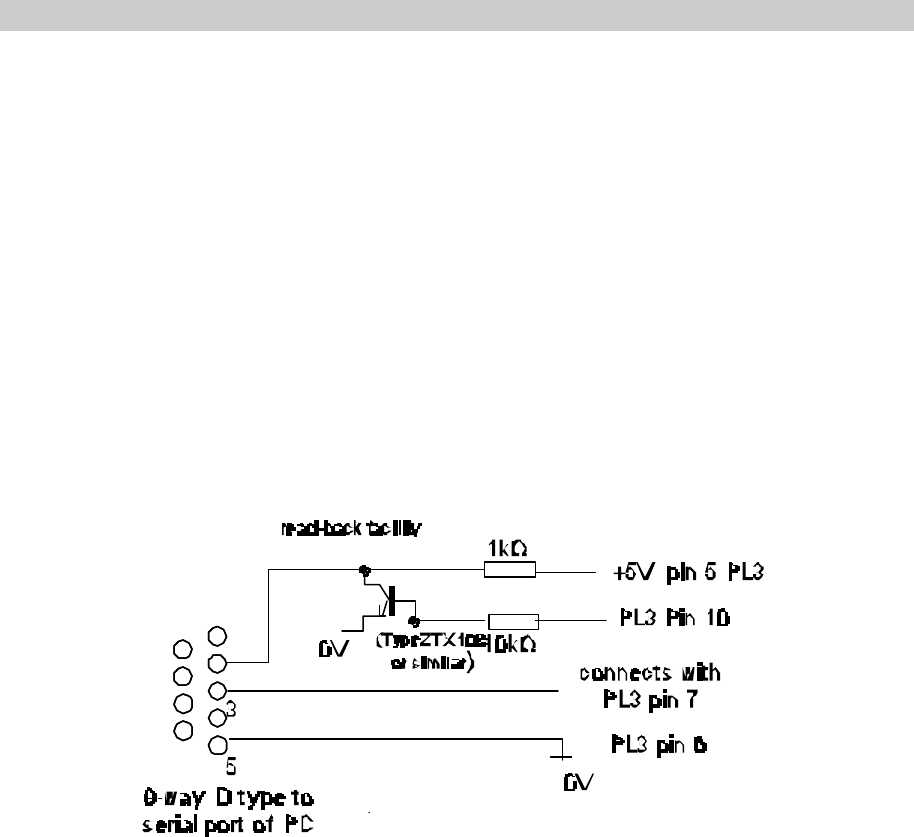
Figure 2 Programming adaptor
FREQUENCY PROGRAMMING
The SR600 has an internal memory which can store up to 128 RF channels (16 randomly
programmed and 112 sequentially programmed). The frequency and set-up information
is programmed into the unit by a synchronous PCM interface protocol.
The software supplied with the SR600 receiver is the STSRn00.exe program. The software
can be run on a PC with the serial port connected to PL3 of the SR600 receiver via a
suitable adaptor as shown in Figure 2. For the read-back function PL3 pin 10 of the
receiver must be connected to pin 2 of the PC serial port via a buffer circuit. A 1k pull-up
resistor to +5V must also be provided as shown.

RUNNING THE SOFTWARE
1. Connect SR600 to a suitable supply and to the PC using the programming adaptor.
2. Insert the STSRn00PRG disk into drive A and type:
A:STSRn00 <return>
3. The user is then prompted to enter the serial port number of his PC which is used
to communicate with the SR600 receiver. Enter 1 or 2.
4. Next there is a prompt to select STn00 or SRn00. Enter 2 for the SR600
5. Next is the prompt to select freq. range: 1 : ST100 (125 - 180MHz)
2 : ST/SR500 (400 - 650MHz)
3 : ST/SR800 (800 - 880MHz)
After the software has successfully loaded the main menu screen is displayed as shown in
Figure 3. The screen shows the default settings which are entered at factory set-up. These
default settings will be displayed whenever the STSRn00 software is run.
Please note that mouse operation is not supported with this program.
FREQUENCY STORAGE
The internal PIC processor allows for both random allocated frequencies and sequential
channels. The program displays the 16 (as channel 0/ to 15) random channels on the main
screen. If a sequential table is used then these are stored in channels 16 to 127. These
cannot be displayed or printed out.
To simplify the situation, the first 16 channels of the sequential table can be copied to the
random channel by pressing the F2 button.
The first 8 channels (0 to 7) can be selected using the serial interface or the parallel
interface, as described later.

STSRn00 Programmer v.1.0.02
Chan 0 458.5 MHz << Comparison freq. 12.5 KHz
Chan 1 458.5125 MHz Ref. (TCXO) freq. 12. 8 MHz
Chan 2 458.525 MHz Parallel channel select
Chan 3 458.5375 MHz
Chan 4 458.55 MHz
Chan 5 458.5625 MHz
Chan 6 458.575 MHz COMMANDS:
Chan 7 458.5875 MHz
Chan 8 458.6 MHz F2 :copy Ch 16-31 to Ch 0-15
Chan 9 458.6125 MHz F3 :change comparison frequency
Chan 10 458.625 MHz F4 :set parallel ch. mode
Chan 11 458.6375MHz F5 :read from unit
Chan 12 458.65 MHZ F6 :program unit
Chan 13 458.6625MHz F7 :program serial channel
Chan 14 458.675 MHz F12 :QUIT
Chan 15 458.6875MHz
Start table 458.7 MHz
Max. Freq. 458.95 MHz Sequential frequencies, Chan. 16 to 127
Table step 1 x 12.5 kHz
Figure 3
NOTES:
1. The reference (TXCO) frequency is not programmable.
2. The readback function (F5) reads the current settings from the unit into the PC.
3. Function F6 (program the unit) is only enabled after the read-back, (refer to Figure
2). This function re-programs the unit connected.
4. A value for each parameters has to be entered.
5. Only channel 0 to 15 frequencies can be displayed by this software explicitly.
6. Sequential channel table is displayed as start, step and stop frequencies.
Serial channel selection
The unit defaults to serial channel selection whenever the software is run. Selecting the F7
function key prompts the user to enter the new serial channel number which is then
displayed in ‘Serial channel selected’.

Parallel channel selection
To enable parallel channel selection mode press the F4 (Parallel channel mode) function
key, The screen then displays ‘parallel channel selected’.
Three inputs RB1, RB3 and RB3 applied via PL3 to pin 8, pin 9 and pin 10 respectively,
select the operating channel as shown in the following table.
CHANNEL SELECTION
PIN 10 PIN 9 PIN 8 CHANNEL
LOW LOW LOW 7
LOW LOW HIGH 6
LOW HIGH LOW 5
LOW HIGH HIGH 4
HIGH LOW LOW 3
HIGH LOW HIGH 2
HIGH HIGH LOW 1
HIGH HIGH HIGH 0
The logic levels are : LOW < 0.8V
HIGH > 2V or floating
Programming random channels
Random channels between 0 and 15 can be entered using the Up 8 and Down 9 arrow keys
and then entering the required operating frequency. The entered value must be an integer
multiple of comparison frequency otherwise an ‘invalid’ message is displayed.
Programming sequential channels
To generate a new frequency table the following parameter values must be entered:
- start frequency
- the table step as a multiple of comparison frequency.
The maximum frequency is calculated from the start table frequency and the table step..
Therefore if the calculation exceeds the maximum frequency then this parameter will be
increased automatically.
When the frequency table has been generated the user then selects F6 to program the unit,
assuming the unit has been read before.
The function key F2 can be used to copy the contents of channel 16-31 to channel 0 - 15 to
ease sequential programming.

Programming from customer equipment
In the event of a customer wishing to program the SR600 receiver from his own equipment
then the following data sequence must be used allowing 5ms between the characters in the
data stream:
1200 baud, RS232 levels, 1 start bit - 8 bit data - no parity - 1 stop bit
40 (decimal 64) synchronising code
7 bit channel 0 - 127 (bit 7 = 0)
95 (decimal 149) confirmation byte
RANGE INFORMATION
The following table gives an indication of the typical ranges to be expected between a
transmitter and receiver that have simple end-fed dipole antennas.
The following assumptions have been made in the calculations:
line-of-sight between antennas
0dB gain for the transmitter and receiver antennas
0dB loss for connectors and cables between the antenna and the radio connector
20dB fade and environmental margin
-100dBm received signal strength, allowing for digital and analogue signals
Range versus TX power
Frequency (MHz) Power (mW) Power (dBm) Range
(km) Miles
600 1mW 00.4 0.3
600 10mW 10 1.3 0.8
600 25mW 14 2.0 1.2
600 100mW 20 4.0 2.5
600 500mW 27 8.9 5.5

Wood and Douglas Ltd
Lattice House, Baughurst Road, Tadley, Hampshire RG26 5LP 1892 1274
Tel: +44(0) 118 981 1444. Fax: +44(0) 118 981 1567 1.0/September 2000
TECHNICAL SPECIFICATION
Frequency range :580 - 625MHz
Switching bandwidth :8MHz
Frequency stability :+/-2.5ppm
Number of RF channels :up to 128 (16 randomly programmed, 112 sequential),
serial select/reprogram, 1200 baud RS232 or
1 of 8 parallel select (10 pin option)
Channel switching delay :<50mS across switching bandwidth
Channel spacing :25kHz
Modulation type :F3D
Spurious emissions
(conducted & radiated) :in accordance with ETS/CEPT specifications
Supply voltage :6-12 DC, -ve earth
Supply current at 7.2V :<40mA
Interface connections :2 + 10 pin 0.1" header
RF connection :3 pin 0.1" header
Operating temperature :-30oC to +55oC
Storage temperature :-30oC to +70oC
Weight :35g
Size :60 x 39 x 15mm (2.36 x 1.53 x 0.59 inches)
Type approval :
Sensitivity :<-117 dBm for 12dB SINAD (25 kHz)
(Measured with a flat audio response)
Image/spurii :>60dB
Intermodulation response
rejection :>60dB
Blocking :>75dB
Intermediate frequencies :45 MHz and 455kHz
Adjacent chan. selectivity :>60dB for 12.5kHz channel spacing
>70dB for 25kHz channel spacing
Audio response :9Hz to 6kHz at -3dB (25kHz channels)
Recovered audio level :>250mV p-p (±20%) into 10kS
Squelch type :Noise operated open collector output
General facilities :RSSI output (0.5 to +2V nominal)
+5V output
Independent data output