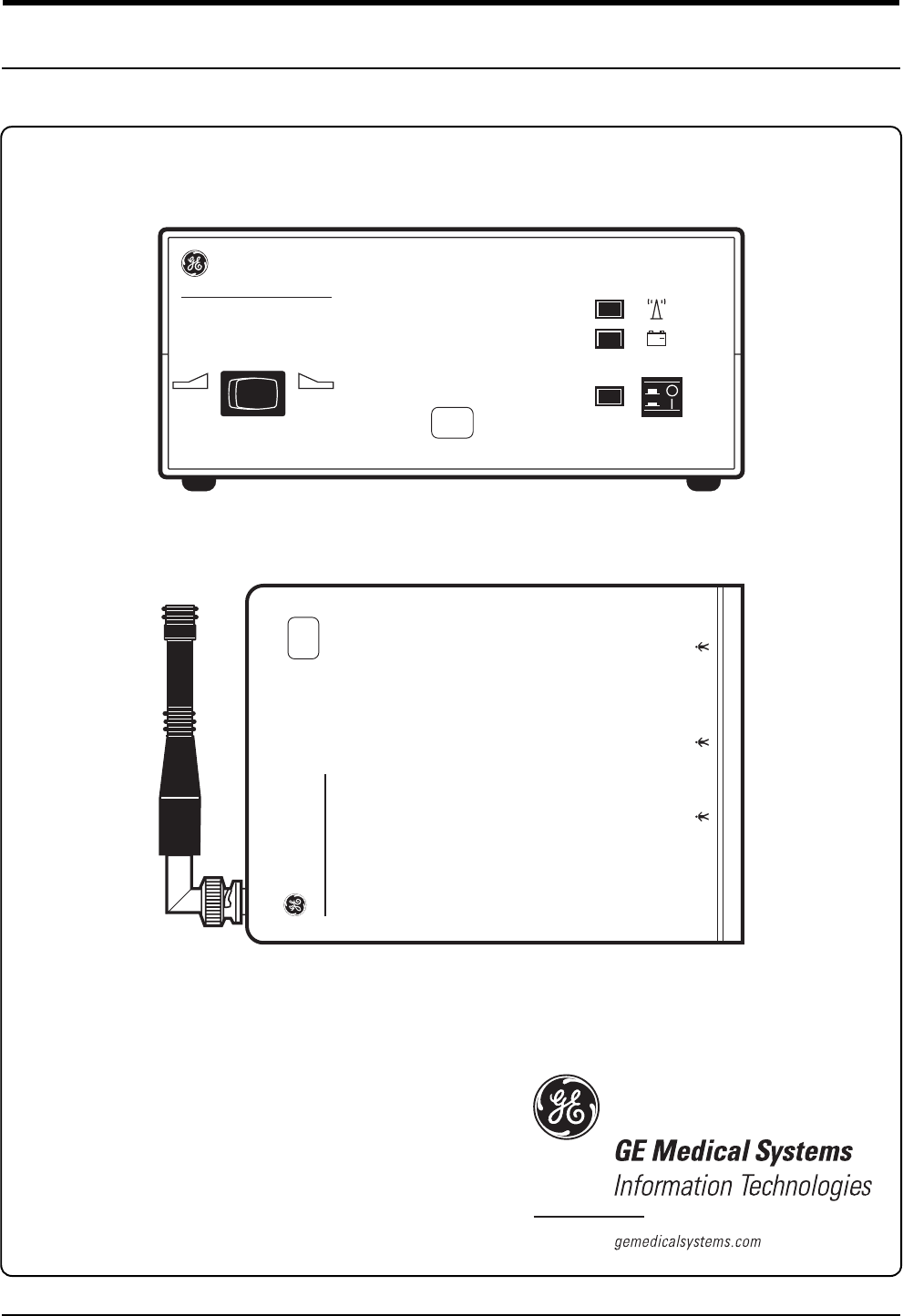
GE Medical Systems Information Technologies 340MT WMTS Transmitter User Manual
GE Medical Systems Information Technologies Inc. WMTS Transmitter
Contents
Ex 13b service manual

Corometrics Model 340
SERVICE MANUAL MANUAL P/N 2006920-001 REV. A
IUPTOCO
+
~
XXX
340 Telemetry Receiver
REFER TO MANUAL FOR PROPER TRANSDUCERS
ULTRASOUND ECG UA
XXX
340 Telemetry Transmitter
Corometrics Model 340
SERVICE MANUAL MANUAL P/N 2006920-001 REV. A
IUPTOCO
+
~
XXX
340 Telemetry Receiver
REFER TO MANUAL FOR PROPER TRANSDUCERS
ULTRASOUND ECG UA
XXX
340 Telemetry Transmitter

Corometrics and Marquette are registered trademarks of GE Medical Systems Information Technologies. GE is a registered
trademark of General Electric Company. All other product and brand names are trademarks or registered trademarks of their
respective companies. ©2001 GE Medical Systems Information Technologies. All rights reserved. No part of this manual
may be reproduced without the permission of GE Medical Systems Information Technologies.
GUARANTEE
All equipment sold by GE Medical Systems Information Technologies, is fully guaranteed as to
materials and workmanship for a period of 1 year. Information Technologies reserves the right to
perform guarantee service operations in its own factory, at an authorized repair station, or in the
customer’s installation.
Our obligation under this guarantee is limited to repairing, or, at our option, replacing any
defective parts of our equipment, except fuses or batteries, without charge, if such defects occur in
normal service.
Claims for damage in shipment should be filed promptly with the transportation company. All
correspondence covering the instrument should specify the model and serial numbers.
GE MEDICAL SYSTEMS Information Technologies
A GE Medical Systems Company
Revision A: 04-01
GE Medical Systems Information Technologies will make available on request such circuit
diagrams, component diagrams, component parts lists, descriptions, calibration instructions, or
other information which will assist the users or appropriately qualified technical personnel to
repair those parts of the equipment which are classified by Information Technologies as
repairable. Refer to the service manual for further information.
CAUTION: In the United States of America, Federal Law restricts this device to sale by or
on the order of a physician.
!
World Headquarters
8200 West Tower Avenue
Milwaukee, WI 53223 USA
Tel: +414.355.5000
800.558.5120 (US only)
Fax: +414.355.3790
Internet: www.gemedicalsystems.com
Europe / Middle East / Africa
Postfach 60 02 65
D-79032 Freiburg Germany
Tel: +49.761.45.43.0
Fax: +49.761.45.43.233
Asia
11th Floor, The Lee Gardens
33 Hysan Avenue
Causeway Bay Hong Kong
Tel: +852.2100.6300
Fax: +852.2100.6292

Revision A Model 340 Telemetry System i
2006920-001
Contents
Figures . . . . . . . . . . . . . . . . . . . . . . . . . . . . . . . . . . . . . . . . . . v
Tables . . . . . . . . . . . . . . . . . . . . . . . . . . . . . . . . . . . . . . . . . . vii
Preface Overview of Telemetry Systems . . . . . . . . . . . . . . . . . . . . ix
About Your System . . . . . . . . . . . . . . . . . . . . . . . . . . . . . . . . . . . . . . . . . . . . . . . . . . . . x
Model 340 Original Release . . . . . . . . . . . . . . . . . . . . . . . . . . . . . . . . . . . . . . . . . . . .x
Model 340 Plus . . . . . . . . . . . . . . . . . . . . . . . . . . . . . . . . . . . . . . . . . . . . . . . . . . . . .x
Model 340M . . . . . . . . . . . . . . . . . . . . . . . . . . . . . . . . . . . . . . . . . . . . . . . . . . . . . . . .x
Identifying Your System . . . . . . . . . . . . . . . . . . . . . . . . . . . . . . . . . . . . . . . . . . . . . . . xi
Identifying Model 340 Original Release and Model 340 Plus Telemetry Systems . . xi
Identifying a Model 340M Telemetry System . . . . . . . . . . . . . . . . . . . . . . . . . . . . . xii
1Safety . . . . . . . . . . . . . . . . . . . . . . . . . . . . . . . . . . . . . . . . . 1-1
General Information . . . . . . . . . . . . . . . . . . . . . . . . . . . . . . . . . . . . . . . . . . . . . . . . . . 1-2
General Use . . . . . . . . . . . . . . . . . . . . . . . . . . . . . . . . . . . . . . . . . . . . . . . . . . . . . .1-2
Responsibility of the Manufacturer . . . . . . . . . . . . . . . . . . . . . . . . . . . . . . . . . . . . .1-2
Definitions of Terminology . . . . . . . . . . . . . . . . . . . . . . . . . . . . . . . . . . . . . . . . . . . . 1-3
Equipment Safety Information . . . . . . . . . . . . . . . . . . . . . . . . . . . . . . . . . . . . . . . . . 1-4
Warnings . . . . . . . . . . . . . . . . . . . . . . . . . . . . . . . . . . . . . . . . . . . . . . . . . . . . . . . .1-4
Cautions . . . . . . . . . . . . . . . . . . . . . . . . . . . . . . . . . . . . . . . . . . . . . . . . . . . . . . . . 1-7
Equipment Symbols . . . . . . . . . . . . . . . . . . . . . . . . . . . . . . . . . . . . . . . . . . . . . . . . . 1-8
FCC Information . . . . . . . . . . . . . . . . . . . . . . . . . . . . . . . . . . . . . . . . . . . . . . . . . . . . . 1-9
FCC Rules Compliance . . . . . . . . . . . . . . . . . . . . . . . . . . . . . . . . . . . . . . . . . . . . .1-9
FCC RF Exposure Compliance . . . . . . . . . . . . . . . . . . . . . . . . . . . . . . . . . . . . . . .1-9
FCC Service Information . . . . . . . . . . . . . . . . . . . . . . . . . . . . . . . . . . . . . . . . . . . .1-9
Wireless Medical Telemetry Service . . . . . . . . . . . . . . . . . . . . . . . . . . . . . . . . . 1-10

ii Model 340 Telemetry System Revision A
2006920-001
2Introduction . . . . . . . . . . . . . . . . . . . . . . . . . . . . . . . . . . . . 2-1
Product Summary . . . . . . . . . . . . . . . . . . . . . . . . . . . . . . . . . . . . . . . . . . . . . . . . . . . 2-2
Product Features . . . . . . . . . . . . . . . . . . . . . . . . . . . . . . . . . . . . . . . . . . . . . . . . . . . . 2-3
3Controls, Indicators, and Connectors . . . . . . . . . . . . . . . 3-1
Receiver . . . . . . . . . . . . . . . . . . . . . . . . . . . . . . . . . . . . . . . . . . . . . . . . . . . . . . . . . . . 3-2
Receiver Front Panel . . . . . . . . . . . . . . . . . . . . . . . . . . . . . . . . . . . . . . . . . . . . . . .3-2
Receiver Rear Panel . . . . . . . . . . . . . . . . . . . . . . . . . . . . . . . . . . . . . . . . . . . . . . 3-4
Transmitter . . . . . . . . . . . . . . . . . . . . . . . . . . . . . . . . . . . . . . . . . . . . . . . . . . . . . . . . . 3-6
Transmitter Bottom Panel . . . . . . . . . . . . . . . . . . . . . . . . . . . . . . . . . . . . . . . . . . .3-6
Transmitter Top Panel . . . . . . . . . . . . . . . . . . . . . . . . . . . . . . . . . . . . . . . . . . . . . 3-8
Transmitter Rear Panel Battery Compartment . . . . . . . . . . . . . . . . . . . . . . . . . . 3-10
4Theory of Operation . . . . . . . . . . . . . . . . . . . . . . . . . . . . . 4-1
Transmitter Board (No. 2003708-001) . . . . . . . . . . . . . . . . . . . . . . . . . . . . . . . . . . . 4-2
Ultrasound . . . . . . . . . . . . . . . . . . . . . . . . . . . . . . . . . . . . . . . . . . . . . . . . . . . . . . .4-2
UA . . . . . . . . . . . . . . . . . . . . . . . . . . . . . . . . . . . . . . . . . . . . . . . . . . . . . . . . . . . . 4-4
ECG . . . . . . . . . . . . . . . . . . . . . . . . . . . . . . . . . . . . . . . . . . . . . . . . . . . . . . . . . . . .4-4
Control Circuitry . . . . . . . . . . . . . . . . . . . . . . . . . . . . . . . . . . . . . . . . . . . . . . . . . . .4-5
Power Supply . . . . . . . . . . . . . . . . . . . . . . . . . . . . . . . . . . . . . . . . . . . . . . . . . . . . 4-6
Telemetry Receiver Board Circuitry (No. 13856A) . . . . . . . . . . . . . . . . . . . . . . . . . 4-7
The RF Receiver . . . . . . . . . . . . . . . . . . . . . . . . . . . . . . . . . . . . . . . . . . . . . . . . . .4-7
Receiver Encoded Modulation . . . . . . . . . . . . . . . . . . . . . . . . . . . . . . . . . . . . . . . 4-8
TOCO Channel . . . . . . . . . . . . . . . . . . . . . . . . . . . . . . . . . . . . . . . . . . . . . . . . . . 4-9
ECG Channel . . . . . . . . . . . . . . . . . . . . . . . . . . . . . . . . . . . . . . . . . . . . . . . . . . . . .4-9
Ultrasound Channel . . . . . . . . . . . . . . . . . . . . . . . . . . . . . . . . . . . . . . . . . . . . . . 4-10
Power Supply Circuitry . . . . . . . . . . . . . . . . . . . . . . . . . . . . . . . . . . . . . . . . . . . . .4-10
Telemetry Transmitter Carrier Board (2003713-001) . . . . . . . . . . . . . . . . . . . . . . 4-11
Telemetry Receiver Carrier Board (2004163-001) . . . . . . . . . . . . . . . . . . . . . . . . . 4-12

Revision A Model 340 Telemetry System iii
2006920-001
5Calibration . . . . . . . . . . . . . . . . . . . . . . . . . . . . . . . . . . . . . 5-1
FCC Service Information . . . . . . . . . . . . . . . . . . . . . . . . . . . . . . . . . . . . . . . . . . . . . . 5-2
Test Equipment . . . . . . . . . . . . . . . . . . . . . . . . . . . . . . . . . . . . . . . . . . . . . . . . . . . . . 5-3
Receiver Calibration . . . . . . . . . . . . . . . . . . . . . . . . . . . . . . . . . . . . . . . . . . . . . . . . . 5-4
Accessing the Receiver Board . . . . . . . . . . . . . . . . . . . . . . . . . . . . . . . . . . . . . . . .5-4
Power Supply . . . . . . . . . . . . . . . . . . . . . . . . . . . . . . . . . . . . . . . . . . . . . . . . . . . 5-5
Ultrasound Channel . . . . . . . . . . . . . . . . . . . . . . . . . . . . . . . . . . . . . . . . . . . .5-5
TOCO Channel . . . . . . . . . . . . . . . . . . . . . . . . . . . . . . . . . . . . . . . . . . . . . 5-6
ECG Channel . . . . . . . . . . . . . . . . . . . . . . . . . . . . . . . . . . . . . . . . . . . . 5-7
Mode Controls . . . . . . . . . . . . . . . . . . . . . . . . . . . . . . . . . . . . . . . . . . 5-8
RF Carrier Detect . . . . . . . . . . . . . . . . . . . . . . . . . . . . . . . . . . . . . . . . . . . . . . . .5-9
Mode Outputs . . . . . . . . . . . . . . . . . . . . . . . . . . . . . . . . . . . . . . . . . . . . . . . . . . .5-10
Pulsed Doppler Ultrasound Audio Converter . . . . . . . . . . . . . . . . . . . . . . . . . . . .5-10
Ultrasound Modulator . . . . . . . . . . . . . . . . . . . . . . . . . . . . . . . . . . . . . . . . . . . . . 5-11
Transmitter Calibration . . . . . . . . . . . . . . . . . . . . . . . . . . . . . . . . . . . . . . . . . . . . . . 5-12
UA Channel . . . . . . . . . . . . . . . . . . . . . . . . . . . . . . . . . . . . . . . . . . . . . . . . . . . . .5-12
ECG Channel . . . . . . . . . . . . . . . . . . . . . . . . . . . . . . . . . . . . . . . . . . . . . . . . . . . .5-12
Main Oscillator . . . . . . . . . . . . . . . . . . . . . . . . . . . . . . . . . . . . . . . . . . . . . . . . . . 5-13
Power Supply . . . . . . . . . . . . . . . . . . . . . . . . . . . . . . . . . . . . . . . . . . . . . . . . . . . .5-13
6Maintenance . . . . . . . . . . . . . . . . . . . . . . . . . . . . . . . . . . . 6-1
General Cleaning Precautions . . . . . . . . . . . . . . . . . . . . . . . . . . . . . . . . . . . . . . . . . 6-2
Cleaning the Transmitter and Receiver . . . . . . . . . . . . . . . . . . . . . . . . . . . . . . . . . . 6-3
7Troubleshooting . . . . . . . . . . . . . . . . . . . . . . . . . . . . . . . . 7-1
Problem Chart . . . . . . . . . . . . . . . . . . . . . . . . . . . . . . . . . . . . . . . . . . . . . . . . . . . . . . 7-2
8Technical Specifications . . . . . . . . . . . . . . . . . . . . . . . . . 8-1
Transmitter . . . . . . . . . . . . . . . . . . . . . . . . . . . . . . . . . . . . . . . . . . . . . . . . . . . . . . . . . 8-2
Receiver . . . . . . . . . . . . . . . . . . . . . . . . . . . . . . . . . . . . . . . . . . . . . . . . . . . . . . . . . . . 8-4
9Drawings . . . . . . . . . . . . . . . . . . . . . . . . . . . . . . . . . . . . . . 9-1


Revision A Model 340 Telemetry System v
2006920-001
Figures
Figure 1-1.
Model 340 or Model 340 Plus REF Number. . . . . . . . . . . . . . . . . . . . . . . . . . . . . . . . . .xi
Figure 1-2.
Model 340M REF Number . . . . . . . . . . . . . . . . . . . . . . . . . . . . . . . . . . . . . . . . . . . . . . xii
Figure 3-1.
Receiver Front Panel . . . . . . . . . . . . . . . . . . . . . . . . . . . . . . . . . . . . . . . . . . . . . . . . . .3-2
Figure 3-2.
Receiver Rear Panel. . . . . . . . . . . . . . . . . . . . . . . . . . . . . . . . . . . . . . . . . . . . . . . . . . .3-4
Figure 3-3.
Transmitter Bottom Panel. . . . . . . . . . . . . . . . . . . . . . . . . . . . . . . . . . . . . . . . . . . . . . .3-6
Figure 3-4.
Transmitter Top Panel . . . . . . . . . . . . . . . . . . . . . . . . . . . . . . . . . . . . . . . . . . . . . . . . .3-8
Figure 3-5.
Transmitter Rear Panel Battery Compartment . . . . . . . . . . . . . . . . . . . . . . . . . . . . . .3-10
Figure 5-1.
Summary of Test Equipment . . . . . . . . . . . . . . . . . . . . . . . . . . . . . . . . . . . . . . . . . . . .5-3
For your notes

Revision A Model 340 Telemetry System vii
2005920-001
Tables
Table 1-1.
Definitions of Terminology . . . . . . . . . . . . . . . . . . . . . . . . . . . . . . . . . . . . . . . . . . . . . .1-3
Table 1-2.
Equipment Symbols . . . . . . . . . . . . . . . . . . . . . . . . . . . . . . . . . . . . . . . . . . . . . . . . . . .1-8
Table 1-3.
FCC Rules Compliance . . . . . . . . . . . . . . . . . . . . . . . . . . . . . . . . . . . . . . . . . . . . . . . .1-9
Table 2-1.
Summary of Monitor Parameters . . . . . . . . . . . . . . . . . . . . . . . . . . . . . . . . . . . . . . . . .2-3
Table 3-1.
Receiver Front Panel . . . . . . . . . . . . . . . . . . . . . . . . . . . . . . . . . . . . . . . . . . . . . . . . . .3-3
Table 3-2.
Receiver Rear Panel. . . . . . . . . . . . . . . . . . . . . . . . . . . . . . . . . . . . . . . . . . . . . . . . . . .3-5
Table 3-3.
Transmitter Bottom Panel. . . . . . . . . . . . . . . . . . . . . . . . . . . . . . . . . . . . . . . . . . . . . . .3-7
Table 3-4.
Transmitter Top Panel . . . . . . . . . . . . . . . . . . . . . . . . . . . . . . . . . . . . . . . . . . . . . . . . .3-9
Table 5-1.
Power Supply Voltages. . . . . . . . . . . . . . . . . . . . . . . . . . . . . . . . . . . . . . . . . . . . . . . . .5-5
Table 5-2.
Band-Pass Filter Center Frequencies and –3 dB Points . . . . . . . . . . . . . . . . . . . . . . .5-8
Table 5-3.
Center Frequencies of Tone Decoders. . . . . . . . . . . . . . . . . . . . . . . . . . . . . . . . . . . . .5-8
Table 5-4.
Tone Decoder Output Locks. . . . . . . . . . . . . . . . . . . . . . . . . . . . . . . . . . . . . . . . . . . . .5-9
Table 5-5.
Open Collector Transistor Switch Testing . . . . . . . . . . . . . . . . . . . . . . . . . . . . . . . . .5-10
Table 7-1.
Troubleshooting . . . . . . . . . . . . . . . . . . . . . . . . . . . . . . . . . . . . . . . . . . . . . . . . . . . . . .7-2
For your notes

Revision A Model 340 Telemetry System ix
2006920-001
Preface
Overview of Telemetry
Systems 1
This chapter provides an overview of the 340 Series of telemetry systems:
About Your System . . . . . . . . . . . . . . . . . . . . . . . . . . . . . . . . . .x
Identifying Your System . . . . . . . . . . . . . . . . . . . . . . . . . . . . . xi

x Model 340 Telemetry System Revision A
2006920-001
Overview of Telemetry Systems: About Your System
About Your System
Due to continuing product innovations, there are three versions of the
Model 340 Telemetry System in hospitals today. All three versions
operate identically from a user’s perspective. Unless otherwise indicated,
the information in this manual applies to all three devices.
Model 340 Original Release
The first release of the Model 340 Telemetry System operates in the
frequency range 430–470 MHz.
Model 340 Plus
The Model 340 Plus also operates in the frequency range 430–470 MHz
offering additional channel numbers than the original Model 340. In
addition, the Model 340 Plus offers flexibility by allowing factory re-
programming to an alternative channel number should interference
become a factor in your location.
Model 340M
The Model 340M operates in the frequency range 608–614 MHz where
the “M” indicates “medical”. The Model 340M complies with the Federal
Communications Commission (FCC) rules for Wireless Medical
Telemetry Service (WMTS). In June 2000, the FCC allocated a new
spectrum allowing potentially life-critical equipment to operate on an
interference-protected basis. Refer to “Wireless Medical Telemetry
Service” on page 1-10 in this manual for additional information.

Revision A Model 340 Telemetry System xi
2006920-001
Overview of Telemetry Systems: Identifying Your System
Identifying Your System
Each GE Medical Systems Information Technologies device has a unique
serial number tag for identification. For each Model 340 Telemetry
System, a reference number can be used to determine if the unit is a
Model 340 Original Release, Model 340 Plus, or Model 340M. If your
device’s REF number begins with “0”, refer to “Identifying Model 340
Original Release and Model 340 Plus Telemetry Systems” next on this
page. If your device’s REF number begins with “3”, refer to “Identifying a
Model 340M Telemetry System” on the following page.
Identifying Model 340 Original Release and
Model 340 Plus Telemetry Systems
If your device’s REF number beings with “0”:
the fourth character identifies receiver or transmitter
the fifth character identifies Model 340 Original Release or
Model 340 Plus
Refer to Figure 1-1.
Figure 1-1. Model 340 or Model 340 Plus REF Number
Example 1: If a serial number label shows REF 0341AAN-501, it is a
receiver from a Model 340 Original Release system.
Example 2: If a serial number label shows REF 0342BBN-XXX00B, it is a
transmitter from a Model 340 Plus system.
0 3 4 _ _ _ _ - _ _ _ _ _ _
Product Code Catalog Number Other Device Characteristics
1 = Telemetry Receiver
2 = Telemetry Transmitter
Version
A = Model 340 Original Release
B = Model 340 Plus
Language/Voltage
Specifiers Three to six characters that
further describe the unit.

xii Model 340 Telemetry System Revision A
2006920-001
Identifying a Model 340M Telemetry System
If your device’s REF number beings with “3”:
the third character identifies receiver or transmitter
the fourth character identifies Model 340M
Refer to Figure 1-2.
Figure 1-2. Model 340M REF Number
Example 1: If a serial number label shows REF 341MCCN-XXX00A, it is
a receiver from a Model 340M telemetry system.
Example 2: If a serial number label shows REF 342MBBN-XXX000B, it
is a transmitter from a Model 340M telemetry system.
3 4 _ M _ _ _ - _ _ _ _ _ _
Product Code Catalog Number Other Device Characteristics
1 = Telemetry Receiver
2 = Telemetry Transmitter
Option/Language/Voltage
Specifiers Three to six characters that
further describe the unit.
M = Model 340 Medical

Revision A Model 340 Telemetry System 1-1
2006920-001
Chapter 1
Safety 1
The information presented in this section is important for the safety of
both the patient and operator and also serves to enhance equipment
reliability. This chapter describes how the terms Danger, Warning,
Caution, Important, and Note are used throughout the manual. In
addition, standard equipment symbols are defined.
This section includes the following important information:
General Information. . . . . . . . . . . . . . . . . . . . . . . . . . . . . . . . 1-2
Definitions of Terminology . . . . . . . . . . . . . . . . . . . . . . . . . . 1-3
Equipment Safety Information . . . . . . . . . . . . . . . . . . . . . . . 1-4
Equipment Symbols . . . . . . . . . . . . . . . . . . . . . . . . . . . . . . . . 1-8
FCC Information . . . . . . . . . . . . . . . . . . . . . . . . . . . . . . . . . . 1-9
!

1-2 Model 340 Telemetry System Revision A
2006920-001
Safety: General Information
General Information
General Use
If any equipment is cold to the touch or below ambient temperature,
allow it to stabilize before use.
To ensure patient safety, use only parts and accessories manufactured or
recommended by GE Medical Systems Information Technologies. Parts
and accessories used shall meet the requirements of IEC 601.1.1.
Disposable devices are intended for single use only. They should not be
reused.
Periodically, and whenever the integrity of the equipment is in doubt,
test all functions.
Refer to the “Maternal/Fetal Monitoring Operator’s Manual” for
information concerning the limitations of internal and external fetal
heart rate monitoring techniques.
Responsibility of the Manufacturer
GE Medical Systems Information Technologies (hereinafter Information
Technologies) is responsible for the effects on safety, reliability, and
performance if:
assembly operations, extensions, readjustments, modifications, or
repairs are carried out by persons authorized by Information
Technoligies;
the electrical installation of the relevant room complies with the
requirements of appropriate regulations; and
the equipment is used in accordance with the instructions for use.

Revision A Model 340 Telemetry System 1-3
2006920-001
Safety: Definitions of Terminology
Definitions of Terminology
Six types of special notices are used throughout this manual. They are:
Danger, Warning, Caution, Contraindication, Important, and Note. The
warnings and cautions in this safety section relate to the equipment in
general and apply to all aspects of the equipment. Be sure to read the
other chapters because there are additional warnings and cautions which
relate to specific features of the equipment.
When grouped, warnings and cautions are listed alphabetically and do
not imply any order of importance.
Table 1-1. Definitions of Terminology
Danger A DANGER notice indicates an imminently
hazardous situation which, if not avoided, will result
in death or serious injury.
Warning A WARNING indicates a potentially hazardous
situation which, if not avoided, could result in death
or serious injury.
Caution
A CAUTION indicates a potentially hazardous
situation which, if not avoided, may result in minor
or moderate injury. Cautions are also used to
avoid damage to equipment.
Contraindication
A CONTRAINDICATION describes any special
symptom or circumstance that renders the use of a
remedy or the carrying out of a procedure
inadvisable, usually because of a risk.
Important An IMPORTANT notice indicates an emphasized
note. It is something you should be particularly
aware of; something not readily apparent.
Note A NOTE indicates a particular point of information;
something on which to focus your attention.

1-4 Model 340 Telemetry System Revision A
2006920-001
Safety: Equipment Safety Information
Equipment Safety Information
Warnings
:$51,1*6
ACCIDENTAL SPILLS—In the event that fluids are
accidentally spilled on the equipment, take the
equipment out of operation and inspect for damage.
APPLICATION—This equipment is not designed for
direct cardiac connection.
CONDUCTIVE CONNECTIONS—Avoid making any
conductive connections to applied parts (patient
connection) which are likely to degrade safety.
CONDUCTIVE PARTS—Ensure that the conductive
parts of the lead electrodes and associated connectors do
not contact other conductive parts including earth.
CONNECTIONS—The correct way to connect a patient
to the transmitter is to plug the electrode leads into the
patient cable which in turn connects to the
transmitter. The receiver is connected to the wall
socket by the power cord. Do not plug the electrode
leads into the power cord, a wall socket, or an extension
cord.
DEFIBRILLATION—This equipment is not designed for
use with defibrillators.
ELECTRICAL SHOCK—To reduce the risk of electrical
shock, do not remove equipment covers. Refer servicing
to qualified personnel.
ELECTROMAGNETIC INTERFERENCE—Be aware
that strong electromagnetic fields may interfere with
equipment operation. Interference prevents the clear
reception of signals by the device. If the hospital is close
to a strong transmitter such as TV, AM or FM radio,
police or fire stations, a HAM radio operator, an airport,
or cellular phone, their signals could be picked up as
signals by the equipment. If you feel interference is
affecting the equipment, contact your Service
Representative to check the equipment in your
environment.

Revision A Model 340 Telemetry System 1-5
2006920-001
Safety: Equipment Safety Information
:$51,1*6
ELECTROSURGERY—The equipment is not designed
for use with high-frequency surgical devices. In addition,
measurements may be affected in the presence of strong
electromagnetic sources such as electrosurgery
equipment.
EXPLOSION HAZARD—Do not use this equipment in
the presence of flammable anesthetics or inside an
oxygen tent.
GROUNDING—Do not defeat the three-wire grounding
feature of the power cord by means of adaptors, plug
modifications, or other methods. A dangerous shock
hazard to both patient and operator may result.
INSTRUCTIONS—For continued and safe use of this
equipment, it is necessary to follow all listed instructions.
However, the instructions provided in this manual in no
way supersede established medical procedures
concerning patient care. The device does not replace
observation and evaluation of the patient, at regular
intervals, by a qualified care provider who will make
diagnoses and decide on treatments and interventions.
INTERFACING OTHER EQUIPMENT—Monitoring
equipment must be interfaced with other types of medical
equipment by qualified biomedical engineering
personnel. Be certain to consult manufacturers’
specifications to maintain safe operation.
LEAKAGE CURRENT TEST—The interconnection of
auxiliary equipment with this device may increase the
total leakage current. When interfacing with other
equipment, a test for leakage current must be performed
by qualified biomedical engineering personnel before
using with patients. Serious injury or death could result
if the leakage current exceeds applicable standards. The
use of accessory equipment not complying with the
equivalent safety requirements of this equipment may
lead to a reduced level of safety of the resulting system.
Consideration relating to the choice shall include: use of
the accessory in the patient vicinity; and evidence that
the safety certification of the accessory has been
performed in accordance with the appropriate IEC 601.1
and/or IEC 601.1.1 harmonized national standard.

1-6 Model 340 Telemetry System Revision A
2006920-001
Safety: Equipment Safety Information
:$51,1*6
LINE ISOLATION MONITOR TRANSIENTS—Line
isolation monitor transients may resemble actual cardiac
waveforms, and thus cause incorrect heart rate
determinations and alarm activation (or inhibition).
MRI USE—Do not use the equipment during MRI
scanning; conducted current could potentially cause
burns.
PATIENT CABLES AND LEADWIRES—Do not use
patient cables and electrode leads that permit direct
connection to electrical sources. Use only “safety” cables
and leadwires. Use of non-safety patient cables and lead
wires creates risk of inappropriate electrical connection
which may cause patient shock or death.
PACEMAKER PATIENTS—Rate meters may continue to
count the pacemaker rate during occurrences of cardiac
arrest or some arrhythmias. Do not rely entirely upon
rate meter alarms. Keep pacemaker patients under close
surveillance. Refer to your monitor’s operator’s manual
for disclosure of the pacemaker pulse rejection capability.
SIMULTANEOUS DEVICES—Do not simultaneously
connect more than one device that uses electrodes to
detect ECG and/or respiration to the same patient. Use
of more than one device in this manner may cause
improper operation of one or more of the devices.
STRANGULATION—Make sure all patient cables,
leadwires, and tubing are positioned away from the
patient’s head to minimize the risk of accidental
strangulation.
WATER BIRTHS—Do not use a fetal or maternal/fetal
monitor to directly monitor patients during water
births, in whirlpool or submersion water baths, during
showers, or in any other situation where the mother is
immersed in water. Doing so may result in electrical
shock hazard.

Revision A Model 340 Telemetry System 1-7
2006920-001
Safety: Equipment Safety Information
Cautions
&$87,216
ANNUAL SERVICING—For continued safety and
performance of the equipment, it is recommended that
the calibration, accuracy, and electrical safety of the
equipment be verified on an annual basis by an
Information Technologies Service Representative.
DAILY INSPECTION—It is essential that the
equipment and accessories be inspected prior to every
use.
ENVIRONMENT—The performance of the equipment
has not been tested in certain areas, such as x-ray and
imaging suites. The equipment is not recommended for
use in these environments.
PERFORMANCE—Report all problems experienced with
the equipment. If the equipment is not working properly,
contact your Service Representative for service. The
equipment should not be used if it is not working
properly.
1-8 Model 340 Telemetry System Revision A
2006920-001
Safety: Equipment Symbols
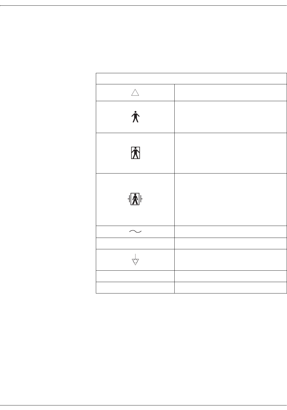
Equipment Symbols
The following is a list of symbols used on products manufactured by
Information Technologies. Some symbols may not appear on your
equipment.
Table 1-2. Equipment Symbols
ATTENTION: Consult accompanying documents.
TYPE B EQUIPMENT. Type B equipment is
suitable for intentional external and internal
application to the patient, excluding direct cardiac
application.
TYPE BF EQUIPMENT. Type BF equipment is
suitable for intentional external and internal
application to the patient, excluding direct cardiac
application. Type BF equipment has an F-type
applied part.
DEFIBRILLATOR-PROOF TYPE BF EQUIPMENT:
Type BF equipment is suitable for intentional
external and internal application to the patient,
excluding direct cardiac application. Type BF
equipment is type B equipment with an F-type
isolated (floating) part. The paddles indicate the
equipment is defibrillator proof.
ALTERNATING CURRENT (AC).
IPX1 DRIP PROOF.
EQUIPOTENTIALITY.
OPOWER OFF: disconnection from the mains.
IPOWER ON: connection to the mains.
!

Revision A Model 340 Telemetry System 1-9
2006920-001
Safety: FCC Information
FCC Information
FCC Rules Compliance
This equipment complies with the FCC rules shown in Table 1-3. (Refer
to “Identifying Your System” on page xi for information about identifying
what type of telemetry system you have in your hospital.) Operation is
subject to the condition that this device does not cause harmful
interference.
FCC RF Exposure Compliance
,03257$17
RF EXPOSURE—To comply with FCC RF exposure
compliance requirements, users should avoid grasping
the antenna for any extended period of time while the
device is in operation.
FCC Service Information
Servicing the radio frequency transmitter and receiver sections of the
Model 340 Telemetry System requires an FCC General Radio Telephone
License.
Any changes or modifications made to the Model 340 Telemetry System
that are not expressly approved by Information Technologies, could void the
user’s authority to operate this equipment.
Table 1-3. FCC Rules Compliance
Telemetry Transmitter Receiver
Model 340 Original Release Part 90 Part 15
Model 340 Plus Part 90 Part 15
Model 340M Part 95 Part 15

1-10 Model 340 Telemetry System Revision A
2006920-001
Safety: FCC Information
Wireless Medical Telemetry Service
This section applies to Model 340M Telemetry Systems only. Refer to
“Identifying Your System” on page xi for information about identifying
what type of telemetry system you have in your hospital.
,03257$17
Operation of a Model 340M Telemetry System requires
prior coordination with a frequency coordinator
designated by the FCC for the Wireless Medical
Telemetry Service.
In June 2000, the FCC allocated new spectrum and established rules for
Wireless Medical Telemetry Service (WMTS) allowing potentially life-
critical equipment to operate on an interference-protected basis.
The frequency allocation for WMTS provides spectrum where the
equipment can operate on a primary basis increasing the reliability of
this important service. The FCC allocated 14 MHz of spectrum for use by
medical telemetry equipment in the 608–614 MHz, 1395–1400 MHz, and
1429–1432 MHz bands. This allocation was based on a needs assessment
conducted by the American Hospital Association (AHA).
The 608–614 MHz band, which corresponds to TV channel 37 had been
reserved for radio astronomy uses, so this action elevates medical
telemetry to a co-primary status with radio astronomy in this band. The
1395–1400 MHz and 1429–1432 MHz bands were government bands
reallocated for non-government use.
WMTS is designated as one of the Citizen’s Band Services in Part 95 of
the rules and licensed by rule to eliminate the possible costs and delays
to obtain individual operator’s licenses. The medical telemetry
equipment is authorized under the certification procedure in Part 2 of
the rules. One or more frequency coordinators maintain a database of all
equipment used in conjunction with WMTS.
For more information visit http://www.fcc.gov.


2-2 Model 340 Telemetry System Revision A
2006920-001
Introduction: Product Summary
Product Summary
The Corometrics Model 340 Telemetry System (receiver and transmitter)
provides a wireless means of transmitting heart rate and uterine activity
signals from an ambulatory mother to a bedside fetal or maternal/fetal
monitor. The system operates with the following Corometrics brand
monitors; if your monitor is not listed, check with your saleperson or
service representative for a more current list.
Model 115
Model 116
Model 118
120 Series*
Model 145
Model 150
Model 151
Model 155
170 Series
127(The Model 340 Telemetry
System does not support fetal
movement detection.
The system monitors ultrasound, ECG (FECG or MECG), and uterine
activity (TOCO or IUPC) signals individually or in combination—
depending on which parameters are available in the fetal or maternal/
fetal monitor. Refer to your monitor’s operator’s manual as needed.
*A 120 Series Monitor requires a Communications Board in order to interface to a Model 340 Telemetry System. If
your monitor does not have this option, an upgrade kit is available as cat. no. (REF) 1559BAO. Contact your
Service Representative for more information.

Revision A Model 340 Telemetry System 2-3
2006920-001
Introduction: Product Features
Product Features
The following is a summary of product features:
Battery operated transmitter provides up to 20 hours* of continuous
transmission when operated with fresh batteries.
A Low Battery indicator, accompanied by an audio indicator, signals
an impending low-battery condition.
A transmitter headset* allows the patient or staff to hear the
ultrasonically detected heartbeats for reassurance as well as to verify
proper transducer placement.
A Signal Quality indicator verifies the strength of the radio
transmission signal.
Transducers are quickly and easily interchangeable amongst the
Model 340 Telemetry System and most Corometrics brand monitors:
Models 116, 118, 150, 151, 155, and 170 Series: transducers are
interchangeable.
120 Series: ECG rectangular connector cables are not compatible;
round connector cables are compatible.
Models 115 and 145: cat. no. (REF) 5600 ultrasound transducers
cannot be used with a Model 340. Use only cat. no. (REF) 5700
transducers when the using a Model 115 or 145 with a Model 340
Telemetry System.
Provides simultaneous monitoring of two heart rates (twins or
maternal/fetal) when used with a monitor supporting these
parameters. Refer to Table 2-1 for a summary of monitor parameters.
,03257$17
INSTRUCTIONS—The operator should review and be
familiar with the operator’s manual for the fetal or
maternal/fetal monitor as well as the "Maternal/Fetal
Monitoring Operator’s Manual".
*Use of the headset will deplete the batteries more rapidly.
Table 2-1. Summary of Monitor Parameters
115 116 118 126 128 129 145 150 151 151D 155 171 172 173 174
TOCO ááááááááá á ááááá
IUPC áááááá áá áá
US ááááááááá á ááááá
FECG áááááá áá áá
MECG ááá ááá

2-4 Model 340 Telemetry System Revision A
2006920-001
For your notes

Revision A Model 340 Telemetry System 3-1
2006920-001
Chapter 3
Controls, Indicators, and
Connectors 3
This section describes all controls, indicators, and connectors on a Model
340 Telemetry System.
Receiver. . . . . . . . . . . . . . . . . . . . . . . . . . . . . . . . . . . . . . . . . . 3-2
Transmitter . . . . . . . . . . . . . . . . . . . . . . . . . . . . . . . . . . . . . . 3-6
3-2 Model 340 Telemetry System Revision A
2006920-001
Controls, Indicators, and Connectors: Receiver
Receiver
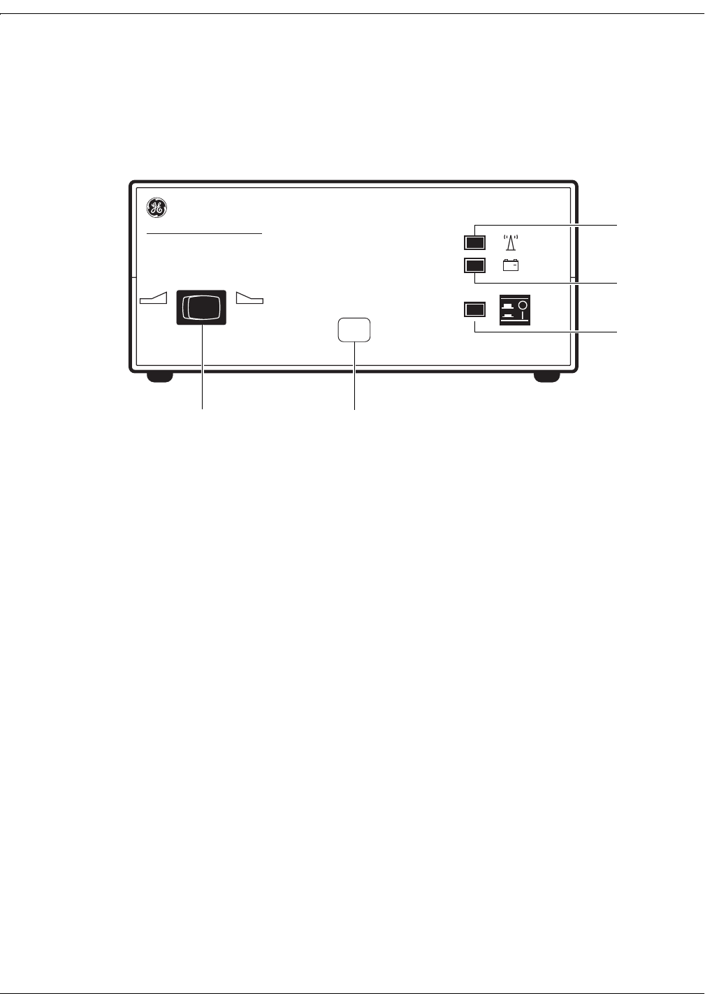
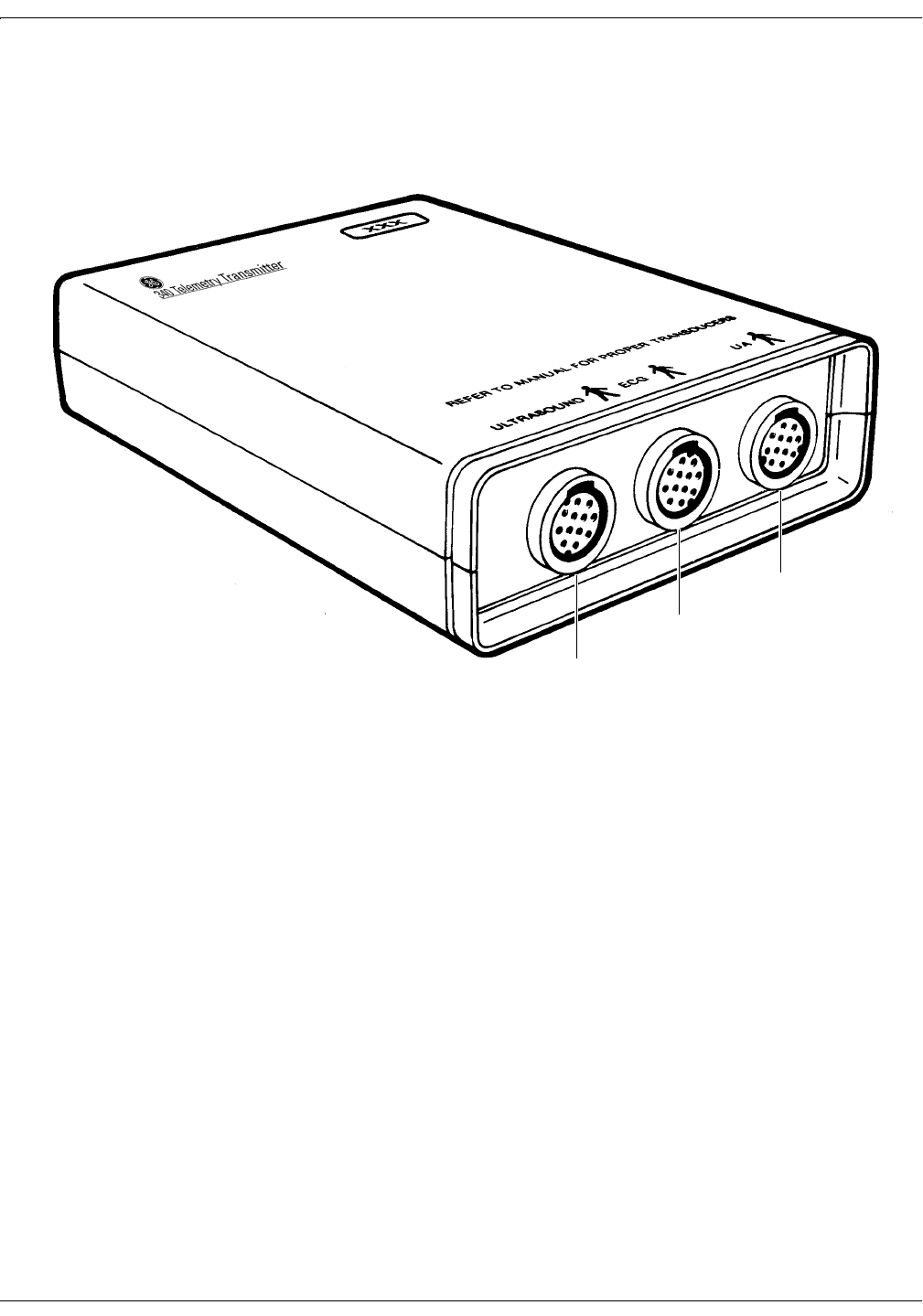
Receiver Front Panel
Figure 3-1. Receiver Front Panel
IUPTOCO
+
~
XXX
340 Telemetry Receiver
AB
C
D
E

Revision A Model 340 Telemetry System 3-3
2006920-001
Controls, Indicators, and Connectors: Receiver
Table 3-1. Receiver Front Panel
Name Description
AUA Mode Selector
Switch
This switch communicates the active uterine
activity mode to the fetal or maternal/fetal monitor:
When monitoring with a tocotransducer, set the
switch to the TOCO position.
When monitoring with an intrauterine pressure
catheter, set the switch to the IUP position.
B Channel Number
The channel number is the customer-designated
receiving frequency of the receiver. For each
telemetry system, the channel number of the
receiver must be identical to the channel number of
the transmitter. Also, if you have more than one
telemetry system, or other RF devices, each
system must have a unique channel number.
CPower Switch and
Indicator
The Power switch turns the receiver on (I) and off
(O). When set to on, the green Power indicator
illuminates.
D Low Battery Indicator
The red Low Battery indicator flashes when you
have approximately 10 minutes of transmitter
battery power remaining. The Low Battery indicator
stops flashing and lights continuously as soon as
the battery is depleted.
E Signal Indicator
The green Signal indicator lights continuously
when the receiver is accepting radio frequency
signals from the transmitter. The Signal indicator
flashes if the signal strength is weak or marginal.
3-4 Model 340 Telemetry System Revision A
2006920-001
Controls, Indicators, and Connectors: Receiver
Receiver Rear Panel
Note: Antenna shown removed.
Figure 3-2. Receiver Rear Panel
ANTENNA
OUTPUTS TO MONITOR
CONNECT TO
COROMETRICS
MONITORS ONLY
ULTRASOUND ECG UA
!
WARNING: TO REDUCE FIRE HAZARD
REPLACE FUSE AS MARKED.
CAUTION
!
120Vac
~
120V ~ 50-60HZ 30W
0.25A SLOW BLOW
A
ED
C
B

Revision A Model 340 Telemetry System 3-5
2006920-001
Controls, Indicators, and Connectors: Receiver
Table 3-2. Receiver Rear Panel
Name Description
AAC Line Connector and
Fuseholder Module
This module houses the AC-line input connector
and the main fuses for the receiver:
100–120 VAC: requires two, 0.25 A slow-blow
fuses.
220–240 VAC: requires two, 0.2 A time-lag
fuses.
BAuxiliary Output
Connector
This connector is used with 120 and 170 Series
Monitors only. Do not use this connection method
for Models 115, 116, 118, 145, 150, 151, and 155
Monitors.
This connector outputs the US, ECG, UA, and
Mark signals, acquired by telemetry, to a 120 or
170 Series Monitor. See the Model 340 Operator’s
Manual for complete interconnection details.
As soon as any telemetry mode is detected, the
front panel of the 120 or 170 Series Monitor is
disabled and all front panel inputs are ignored.
In other words, telemetry and monitor modes
cannot be “mixed and matched’; you must use
telemetry only or direct monitoring only.
For proper operation with a 170 Series Monitor,
disconnect all transducers from the front panel
of the monitor.
CUS, ECG, UA, and Mark
Connectors
These connectors are used with Models 115, 116,
118, 145, 150, 151, and 155 Monitors only. Do not
use this connection method for 120 and 170 Series
Monitors.
Each connector outputs the respective signal,
acquired by telemetry, to the fetal or maternal/fetal
monitor:
US: light grey connector which outputs the
ultrasound signal.
ECG: grey connector which outputs the FECG or
MECG signal.
UA: white connector which outputs the TOCO or
IUPC signal.
Mark: connector which outputs the Event Mark
signal.
See the Model 340 Opreator’s Manual for complete
interconnection details.
D Antenna Connector Twist-on connector for attaching the receiver
antenna.
E Equipotential Lug Binding post terminal directly connected to the
chassis for use as an equipotentiality connection.
3-6 Model 340 Telemetry System Revision A
2006920-001
Controls, Indicators, and Connectors: Transmitter
Transmitter
Transmitter Bottom Panel
Figure 3-3. Transmitter Bottom Panel
A
C
B

Revision A Model 340 Telemetry System 3-7
2006920-001
Controls, Indicators, and Connectors: Transmitter
Table 3-3. Transmitter Bottom Panel
Name Description
A Ultrasound Input
Connect a Corometrics 5700 Series pulsed
Doppler ultrasound transducer to this light gray
receptacle.
Corometrics 5600 Series continuous-wave
ultrasound transducers are not compatible with
the Model 340 Telemetry System. The 5600
Series Transducer was designed for use with
Models 115 and 145 Monitors and Models 320
and 330 Telemetry Systems.
B ECG Input
Connect an FECG cable/legplate or MECG cable
plug to this grey receptacle. This connector is
compatible with all round-connector FECG/MECG
patient cables used with Corometrics-brand
monitors.
C UA Input Connect a tocotransducer, IUPC, or strain gauge
transducer plug to this white receptacle. Contact
your Sales Representative about compatibility.
3-8 Model 340 Telemetry System Revision A
2006920-001
Controls, Indicators, and Connectors: Transmitter
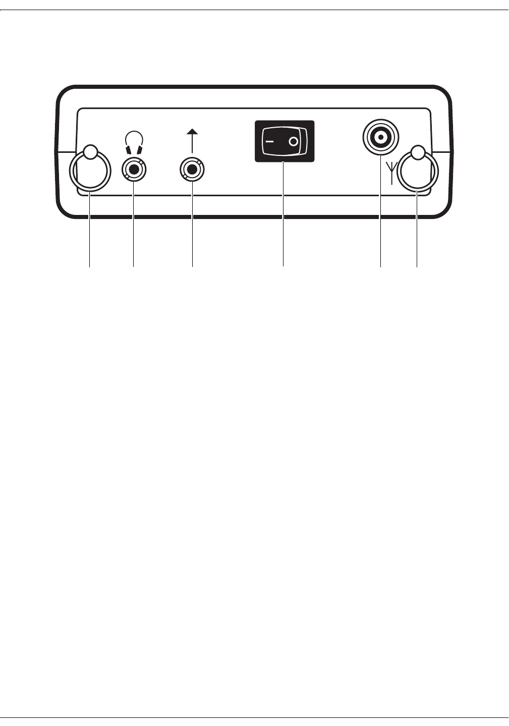
Transmitter Top Panel
Note: Antenna shown removed.
Figure 3-4. Transmitter Top Panel
ABCDEA

Revision A Model 340 Telemetry System 3-9
2006920-001
Controls, Indicators, and Connectors: Transmitter
Table 3-4. Transmitter Top Panel
Name Description
A Loops Loops for attaching the carrying strap.
B Headset Connector Connect the headset to this receptacle to listen to
the fetal heart rate derived from ultrasound.
CRemote Event Mark
Connector
Connect a Corometrics Remote Event Marker to
this receptacle. When the marker’s button is
pressed for at least one second, an event mark
signal is transmitted and one of the following marks
prints on the strip chart paper:
: This annotation is commonly used to record
an “event.” This mark is available on all
Corometrics-brand monitors.
: This annotation is commonly used as an
indication that the mother has perceived fetal
movement. (Refer to your monitor’s operator’s
manual to learn if your monitor supports this
feature. Refer to your monitor’s service manual
for information about enabling the option.)
D Power Switch Moving the switch to the on position (I) turns on the
transmitter; moving the switch to the off position
(O), turns off the transmitter.
E Antenna Connector Twist-on connector for attaching the transmitter
antenna.
F
M
3-10 Model 340 Telemetry System Revision A
2006920-001
Controls, Indicators, and Connectors: Transmitter
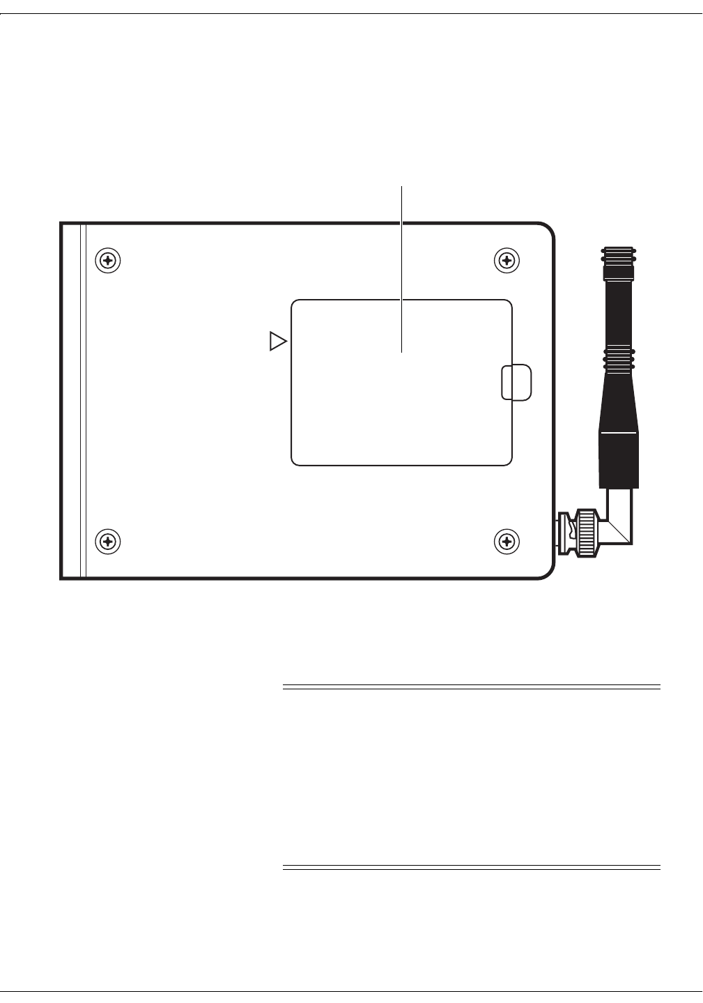
Transmitter Rear Panel Battery Compartment
Figure 3-5. Transmitter Rear Panel Battery Compartment
The battery compartment holds four “AA” alkaline batteries.
&$87,21
BATTERY STRENGTH—When the battery power is low,
the transmitter emits a chirping sound every 4–5
seconds. (For Model 340 Plus and Model 340M Systems,
the frequency of chirping increases as the batteries
become depleted.) The onset of chirping signals
approximately 10 minutes of remaining battery power.
The chirping continues until the battery power is
completely depleted, at which time the transmitter stops
sending data.
DANGER: POSSIBLE EXPLOSION HAZARD IF USED
IN THE PRESENCE OF FLAMMABLE ANESTHETICS.
CAUTION: REFER SERVICE ONLY TO QUALIFIED PERSONNEL
!
BATTERY COMPARTMENT
Battery Compartment

Revision A Model 340 Telemetry System 4-1
2006920-001
Chapter 4
Theory of Operation 4
This section of the manual contains the electronic theory for the Model
340 Maternal/Fetal Telemetry System. The Model 340 Telemetry
System is comprised of a receiver and a transmitter. The electronic
theory for the transmitter (Transmitter Board and Transmitter Carrier
Board) and receiver (Receiver Board and Receiver Carrier Board) is
presented. For complementary information, refer to the schematics and
assembly drawings contained in Chapter 9 of this manual.
This chapter contains the following technical information:
Transmitter Board (No. 2003708-001) . . . . . . . . . . . . . . . . . 4-2
Telemetry Receiver Board Circuitry (No. 13856A). . . . . . . . 4-7
Telemetry Transmitter Carrier Board (2003713-001) . . . . 4-11
Telemetry Receiver Carrier Board (2004163-001) . . . . . . . 4-12

4-2 Model 340 Telemetry System Revision A
2006920-001
Theory of Operation: Transmitter Board (No. 2003708-001)
Transmitter Board (No. 2003708-001)
Ultrasound
The operation of the ultrasound circuitry is controlled by a CMOS
programmable logic device (CPLD). This CPLD also contains the active
circuitry used to form a 4.604 MHZ crystal oscillator, which is the main
system clock from which all board logic timing is derived. The fourth
division (1.151 MHZ) is the operating frequency of the ultrasound
transducer. Ultrasound decoding circuitry in the CPLD generates two
gated bursts of the 1.151 MHz clock division: the first is used to drive the
transducer; the second to run the ring demodulator on the receiver. Both
bursts are buffered by an external latch.
The transducer drive circuitry consists of a FET switch, a transformer,
and a filter. The first gated 1.151 MHz burst from the CPLD is used as
the control signal for the gate of the FET switch. The drain of the switch
in turn drives the primary winding of the transformer. This
configuration creates a burst of 1.151 MHz square waves on the primary
winding during each transmit period. The secondary winding of the
transformer is then coupled to the transducer through a series resonant
tank circuit which is used to filter the square waves on the transformer
output. The transformer, while serving as a coupling device, is also used
to provide an impedance match to the transducer.
The receiver pre-amp consists of a cascode amplifier and an input
matching network. The matching network is configured as a resonant “L”
network and converts the low impedance of the transducer to the high
input impedance of the cascode amplifier. The matching network
provides a low-to-high impedance transformation, in addition to
providing approximately 38 dB of voltage gain. The cascode amplifier
combines a dual FET connected in parallel on the input side, with a
bipolar transistor on the output. The parallel connection of the dual FET
is used to increase amplifier gain (transconductance doubles) while
reducing overall amplifier noise (noise adds in quadrature). The output
of the amplifier is tuned with a parallel resonate tank circuit in the
collector of the transistor section. The cascode amplifier gain is
approximately 12 dB.

Revision A Model 340 Telemetry System 4-3
2006920-001
Theory of Operation: Transmitter Board (No. 2003708-001)
Following the pre-amp is a buffer amplifier and transformer
combination. The buffer stage is unity gain and is used to establish a
high impedance for the pre-amp output. The transformer converts the
single ended pre-amp output to differential for the demodulator that
follows.
The demodulator circuit is composed of a quad FET switch, a difference
amplifier, and a sample-and-hold circuit. The switches are arranged in a
doubly balanced ring detector configuration. When the CPLD generates
the detector burst, the demodulator produces an output that corresponds
to the Doppler shift of the input signal from the transducer. The
differential output of the ring demodulator is then converted to single
ended by the difference amplifier stage. Due to the gating of the detector
stage, a sample-and-hold circuit is used to retain the last output level
while the detector is inactive.
After the detector are four stages of main filters consisting of two high-
pass and two low-pass filters, all active second order. Each filter stage
has a gain of approximately 20 dB (80 dB total gain), and the composite
band-pass filter is 100 to 270 Hz. A gain adjustment in the filters is used
to set the gain for the entire receiver circuit (pre-amp input to filter
output).
Following the main filters is the frequency doubler. This stage is
necessary in order to bring the low frequency content of the Doppler
shifted signals from the transducer up to a more suitable band for the
human ear as well as to prevent disturbance of control signals
transmitted along with the ultrasound audio in the composite
modulation. The doubler consists of a precision full-wave rectifier, an
active band-pass filter, and an audio amplifier. The full-wave rectifier
produces two output peaks for every one peak applied to the input,
effectively doubling the input frequency. However, the rectifier output is
not purely sinusoidal. All undesired frequency components produced by
the rectification process are removed in the next stage—the active band-
pass filter. This filter has a gain of approximately 3 and a band-pass
range of 200 to 500 Hz. The output from this filter is used as a component
in the composite modulation for the transmitter module as well as to
provide the input source for the audio amplifier. The audio amplifier is a
unity-gain current amplifier that provides sufficient current output to
drive a 40 Ω headphone.

4-4 Model 340 Telemetry System Revision A
2006920-001
Theory of Operation: Transmitter Board (No. 2003708-001)
UA
The UA circuitry on the Transmitter Board consists of an
instrumentation amplifier, a secondary amplifier stage, a voltage-
controlled oscillator (VCO), and an active low-pass filter. The
instrumentation amplifier is used both to amplify and to convert the
differential output of a TOCO bridge or IUP device to single ended. This
stage is set for a gain of 100. The second amplifier is used to scale and
filter the signals from the instrumentation amplifier for the VCO input.
This stage has a gain of 13.3 and is offset to accommodate the maximum
usable range of the UA transducers. Feedback components on this stage
are set for a single-pole roll off at 1.6 Hz. The varying voltage levels from
the output of the UA amplifier stages are converted to proportional
changes in frequency in the VCO. This circuit creates a FM subcarrier
with a center frequency of 1.75 kHz and a deviation of ±250 Hz. The
square wave output of the VCO is then filtered by a unity-gain, third-
order, low-pass filter with a breakpoint of 2 kHz. The filter output is used
as part of the composite modulation supplied to the transmitter module.
Power for the TOCO or IUP bridge is provided from a voltage reference
and current amplifier.
ECG
The ECG circuitry is composed of an instrumentation amplifier, a fixed-
gain amplifier, a gain selectable amplifier, a common mode amplifier, a
VCO, and an active low-pass filter. The differential patient signals from
the ECG electrodes are first amplified in the instrumentation stage
which is set to a gain of 10. Additionally, the common mode voltage
present across the gain set resistor on this amplifier is used to create the
right leg drive signal. This common-mode voltage is first buffered in a
unity-gain stage, then inverted in an integrator circuit which amplifies
the common-mode signal. This voltage is fed back to the patient through
the leadwires to help cancel 60 Hz noise. The single-ended output of the
instrumentation stage is then AC coupled to the next amplifier, creating
a single-order, high-pass function with a breakpoint of 6 Hz. This
amplifier operates with a fixed gain of 101 and is rolled off at 80 Hz. The
output of this amplifier is then AC coupled into the finial amplifier stage,
creating an additional high-pass breakpoint at 4 Hz. This is the gain-
selectable amplifier. The gain on this stage is configured by the enabled
mode (FECG or MECG). In the FECG mode, the gain is set at 2.5. In the
MECG mode, the gain is set at 1.25. Feedback components in both modes
set the low-pass roll-off at approximately 42 Hz. The output of this stage
then drives the VCO which has a center frequency of 2.7 kHz and a
deviation of ±250 Hz. This circuit is configured to operate like the VCO
used in the UA channel. The square wave output of the VCO is then
filtered in a unity-gain, second-order, low-pass filter with a breakpoint of
3 kHz. The filter output is used as part of the composite modulation
supplied to the transmitter module.

Revision A Model 340 Telemetry System 4-5
2006920-001
Theory of Operation: Transmitter Board (No. 2003708-001)
Control Circuitry
Mode information, along with battery status and remote mark data, is
transmitted to the receiving unit by use of individual low-frequency
tones. These tones are generated by counters contained within the CPLD
and are a division of the main clock. Each tones is gated on or off
dependent on the state of the mode or function it represents The tones
are summarized as follows: ultrasound mode is 10 Hz; FECG is 20 Hz;
remote mark is 40 Hz; and battery low is 80 Hz. The gated tones from the
CPLD each connect to individual R/C low-pass filters that are then
combined in a summing amplifier with a roll-off of 8 Hz. The summing
gain from each R/C filter is selected to compensate for the attenuation
caused by the low roll-off frequency of this stage. This configuration
effectively provides two stages of low-pass filtering at each frequency.
The output of the summing amplifier connects to a third-order, unity-
gain, active low-pass filter with a cutoff frequency of 90 Hz. This filtered
output, along with the other analog signals, is combined to form the
composite modulation sent to the transmitter module. Mode status for
the patient parameters comes from the individual transducer connectors
via a grounding jumper. The remote mark signal is a switch contact that
is time extended by a comparator with a R/C delay. Low battery is
derived from a comparator that evaluates the raw battery voltage
against a fixed voltage reference. Mode information at the receiver is also
determined by the presence or absence of the two VCO signals. Control of
the VCO enables is accomplished through logic in the CPLD based on the
transducer in use. Level translation for the enable are done by rail-to-
rail op-amps configured as comparators.
There are two states for the low-battery condition. The first indicates
that there is approximately 10 minutes of operating time left in the
batteries. The second state is entered when the battery voltage is only
0.1 V above the minimum required for the power supply regulators to
operate. Both states are determined by comparators from the raw
battery voltage and a fixed voltage reference. When the first low-battery
comparator is activated, the CPLD will gate on the 80 Hz tone to signal
the receiver of the condition as well as activate an audio alarm locally.
The audio alarm is a gated 4.5 kHz tone that drives a piezo speaker. The
gate time is 0.2 s on every 1.6 s. The tone and gate times are a division of
the main clock. When the second comparator is activated, the CPLD
disables all operating modes and the transmitter module (transmitter is
turned off). Additionally, the audio alarm is altered to a 50% duty cycle
with a 0.8 s period. This state is latched. Operation of the unit cannot be
restored until power is cycled off and on. The system will also be disabled
when the unit is operated below +5° C. A temperature sensor in the
CPLD will disable the modes and transmitter module when the
temperature falls below this threshold. This state is not latched. Normal
operation will be restored automatically when the unit returns to the
specified operating temperature range.

4-6 Model 340 Telemetry System Revision A
2006920-001
Theory of Operation: Transmitter Board (No. 2003708-001)
Power Supply
The main power supply for this system is a boot converter/regulator. This
switcher converts the battery voltage to a regulated 6.5 V over a battery
range of 3 to 6 V. The switching frequency of this regulator is
synchronized to a division of the main clock (575 kHz) to reduce noise
that might interfere with operation of the ultrasound circuit. A regulated
–6V supply is generated off this supply using a charge pump/regulator.
This converter is also synchronized to a division of the main clock (18
kHz) to prevent noise. Additional linear regulators operate off the 6.5 V
to generate the +6 V and +5 V required by the system. For noise
considerations, the ultrasound circuitry operates from separate +6 V, +5
V, and +2.5 V regulators.

Revision A Model 340 Telemetry System 4-7
2006920-001
Theory of Operation: Telemetry Receiver Board Circuitry (No. 13856A)
Telemetry Receiver Board Circuitry (No. 13856A)
The RF Receiver
The RF receiver used by the Telemetry Receiver Board provides both the
encoded modulation from the transmitter, as well as a voltage output
that is proportional to the RF signal level received.
The signal level output from the RF receiver is connected to a pair of
comparators configured as a threshold detector and monostable. When
the received signal exceeds the comparator threshold, the first
comparator fires enabling the monostable. The output of the monostable
remains enabled as long as the signal level output from the RF receiver
exceeds the threshold of the first comparator, and for drop outs of less
then one-half second. The output of the monostable, in conjunction with
TTL inverters and transistor drivers, is used to light a set of
complementary LEDs. The LEDs are used on the front panel to indicate
a received signal condition, as well as to provide an overall enable to a set
of OR gates that control FET switches. The FET switches provide the
mode enables to the connected fetal monitor.

4-8 Model 340 Telemetry System Revision A
2006920-001
Theory of Operation: Telemetry Receiver Board Circuitry (No. 13856A)
Receiver Encoded Modulation
The encoded modulation from the receiver is divided into several paths:
the first to extract the mode information; the second to extract the data
signals. Mode information is removed from the composite signal through
a three-pole, active, low-pass filter of 100 Hz. After this stage, a gain
adjustment and an additional two poles of active low-pass filtering with a
gain of four are added. The output of the second low-pass filter connects
to four switched-capacitor, band-pass filters. The 80 Hz band-pass filter
is configured to operate with its own internal R/C clock. The output of
this clock also provides the clock input to a CMOS divider. This divider
provides the additional clocks needed for the other band-pass filters of 40
Hz, 20 Hz, and 10Hz. The outputs of the band-pass filters connect to
individual tone decoders which provide an active TTL low state when a
tone at a decoder’s tuned frequency is present at its input. The outputs
of the tone decoders, along with the lock detect outputs of the PLL
circuits used for ECG and TOCO decoding, provide the gate signals
necessary to control the NOR-gate/FET-switch combination that is used
to activate the different modes in the connected fetal monitor. The mode
enable process for ECG requires additional logic to determine if the ECG
information is FECG or MECG. This is determined by the absence or
presence of the FECG enable tone, in conjunction with the lock detect
output of the ECG phase lock loop (PLL). Two of the tones sent by the
transmitter are not used for mode control but provide a battery low
indication, and a remote mark enable. The remote mark enable is taken
directly off the tone decoder output. The battery low output from the
tone decoder turns on a comparator/astable oscillator which, using a
transistor driver, flashes an LED on the front panel.
The data signals are extracted by first high-passing the composite signal
through a three pole 150 Hz active filter. From that point the data signal
is further separated into a ultrasound, ECG, and TOCO channels.

Revision A Model 340 Telemetry System 4-9
2006920-001
Theory of Operation: Telemetry Receiver Board Circuitry (No. 13856A)
TOCO Channel
The TOCO channel includes an additional three poles of active high-pass
filtering at 1.5 kHz, followed by three poles of active low-pass filtering at
2.0 kHz, followed by a 1.75 kHz active two pole band-pass filter with a
gain of four. The output of this filter chain connect to the input of a PLL
circuit consisting of a FSK decoder, a buffer op-amp, and a differential
amplifier. The differential amplifier converts the frequency modulated
TOCO sub-carrier to amplitude variations that correspond to the output
of the TOCO bridge connected to the transmitter. Gain and offset
adjustments are added in the following amplifier stage which, after
passing through a resistor voltage divider, connect to the UA input of the
connected fetal monitor. The PLL also provides a lock detect output
which is used to enable the UA channel on the fetal monitor.
ECG Channel
The ECG channel operates in a similar manner to the TOCO channel
described previously. The composite signal taken off the output of the
1.5 kHz high-pass filter of the TOCO channel is additionally high-pass
filtered with a three-pole, active filter set to 2.4 kHz The output of the
high-pass filter goes to a two-pole, active, 2.4 kHz band-pass filter with a
gain of 4. The output of the band-pass filter connects to a PLL circuit of
similar design to the one used in the TOCO channel. However, the
output of the ECG PLL is AC coupled and does not require the
differential amplifier or offset adjustments. The output stage is
attenuated through a resistor voltage divider, and is connected to the
ECG inputs of the connected fetal monitor. The lock detect output of the
PLL in conjunction with the FECG enable tone detector provide the mode
enable signals to the monitor.

4-10 Model 340 Telemetry System Revision A
2006920-001
Theory of Operation: Telemetry Receiver Board Circuitry (No. 13856A)
Ultrasound Channel
The ultrasound channel of the receiver consists of the initial 150 Hz
high-pass filter, a three-pole active low-pass filter at 550 Hz, a two-pole
active low-pass filter at 600 Hz with a gain of four, a three-pole active
high-pass filter at 150 Hz, and the last stage of a three-pole active low-
pass filter at 500 Hz. A gain adjustment is inserted between the 550 and
600 Hz low-pass stages. The output of this channel is then connected to a
FET switch which routes the output to either the ultrasound modulator,
or to a frequency halver circuit, depending on whether a continuous-
wave (CW) monitor or pulsed-Doppler monitor is connected.
The modulator stage utilizes a balance modulator with an offset added to
produce amplitude modulation from the audio and the transmitter
carrier supplied by the fetal monitor. The output tank circuit of the
modulator is switched to accommodate the differences in frequency
between the CW and pulsed-Doppler monitors. Detection of the monitor
type is accomplished with a jumper added in the 115 ultrasound
interconnect cable. The frequency halver circuit breaks the ultrasound
audio off into two channels: a frequency channel; and an amplitude
channel. The frequency channel takes the amplified audio off the input
stage, and using a limiter stage, removes most of the amplitude
variations off the audio signal. The limiter consists of an op-amp with
back-to-back diodes in the feedback circuit to limit the output to ±0.6 V.
The output of the limiter is amplified and connected to a zero crossing
detector consisting of an op-amp configured as a comparator. The output
of the zero crossing detector is converted to CMOS levels using a
transistor buffer. The output of the buffer then drives a CMOS D type
flip-flop configured as a divide by 2. The “Q” and “NOT Q” outputs of the
divider are used as the carrier signal in a switching type amplitude
modulator stage. The amplitude channel consists of a precision rectifier
and a three-pole active low-pass filter at 30 Hz which produces the
envelope of the audio signal. The envelope and carrier signals are
combined in a switching type amplitude modulator that consists of four
FET switches and a differential amplifier. The carrier signal alternately
causes the FET switches to route the envelope signal between the
inverting and non-inverting inputs of the differential amplifier. This
produces positive and negative variation at the output of the differential
stage, equal to the envelope amplitude, at a rate of the carrier frequency.
The amplitude modulated signal is then run through three poles of active
low-pass filtering at 500Hz, and three poles of active high-pass filtering
at 100 Hz. The output of the filters are used for the modulator stage
when a pulsed-Doppler ultrasound monitor is connected.
Power Supply Circuitry
The power supply is comprised of a single center tapped secondary
transformer, a bridge rectifier, and filter capacitors to produce an
unregulated positive and negative supply. Three terminal 78 and 79
series regulators are used for the +15,–15, +5, and –5 V supplies. A
three-terminal adjustable regulator is used to supply +12 V to the RF
receiver.

Revision A Model 340 Telemetry System 4-11
2006920-001
Theory of Operation: Telemetry Transmitter Carrier Board (2003713-001)
Telemetry Transmitter Carrier Board (2003713-001)
The Transmitter Carrier Board serves as the connection point for devices
used by the system. The remote mark, headphones, antenna, and battery
pack are all first routed through this board. Additionally, the transmitter
RF module and audio piezo speaker are located on this board. The
battery and external devices connect from the carrier board to the main
board through a 16-pin board transition header. A polyswitch current
limiter and polarity-reversal diode for the battery are used to protect the
circuitry on the Transmitter Board from improperly installed batteries or
component failures.

4-12 Model 340 Telemetry System Revision A
2006920-001
Theory of Operation: Telemetry Receiver Carrier Board (2004163-001)
Telemetry Receiver Carrier Board (2004163-001)
The Receiver Carrier Board houses the RF receiver module. Additional
circuitry to add gain to the two receiver outputs (audio and RSSI) are
also located on this board. A linear regulator is used to reduce the 12 V
from the Receiver Board to the 7.6 V required by the RF module.

Revision A Model 340 Telemetry System 5-1
2006920-001
Chapter 5
Calibration 5
This section of the manual provides a calibration procedure which allows
authorized service personnel to perform an instrument alignment using
a minimum of test equipment. This procedure is not intended to replace
a complete instrument checkout and alignment as performed at the GE
Medical Systems Information Technologies factory. It should be
considered a performance check and troubleshooting guide to be used in
conjunction with other information supplied throughout this service
manual. It is important to mention, this section of the manual is not
intended as a substitute for proper professional training, or familiarity
with the Model 340. Only qualified service personnel should attempt
servicing the Model 340.
This chapter contains the following information:
FCC Service Information. . . . . . . . . . . . . . . . . . . . . . . . . . . . 5-2
Test Equipment . . . . . . . . . . . . . . . . . . . . . . . . . . . . . . . . . . . 5-3
Receiver Calibration. . . . . . . . . . . . . . . . . . . . . . . . . . . . . . . . 5-4
Transmitter Calibration . . . . . . . . . . . . . . . . . . . . . . . . . . . 5-12

5-2 Model 340 Telemetry System Revision A
2006920-001
Calibration: FCC Service Information
FCC Service Information
The UHF Transmitter Module and UHF Receiver Module contained in
the Model 340 Telemetry System are GE Medical systems Information
Technologies factory service items.
,03257$17
FCC LICENSE—You must have an FCC General Radio
Telephone License to service the Model 340 Telemetry
System UHF Transmitter Module or UHF Receiver
Module.
Any changes or modifications made to the Model 340 that are not
expressly approved by Information Technologies could void the users
authority to operate this equipment.
Revision A Model 340 Telemetry System 5-3
2006920-001
Calibration: Test Equipment
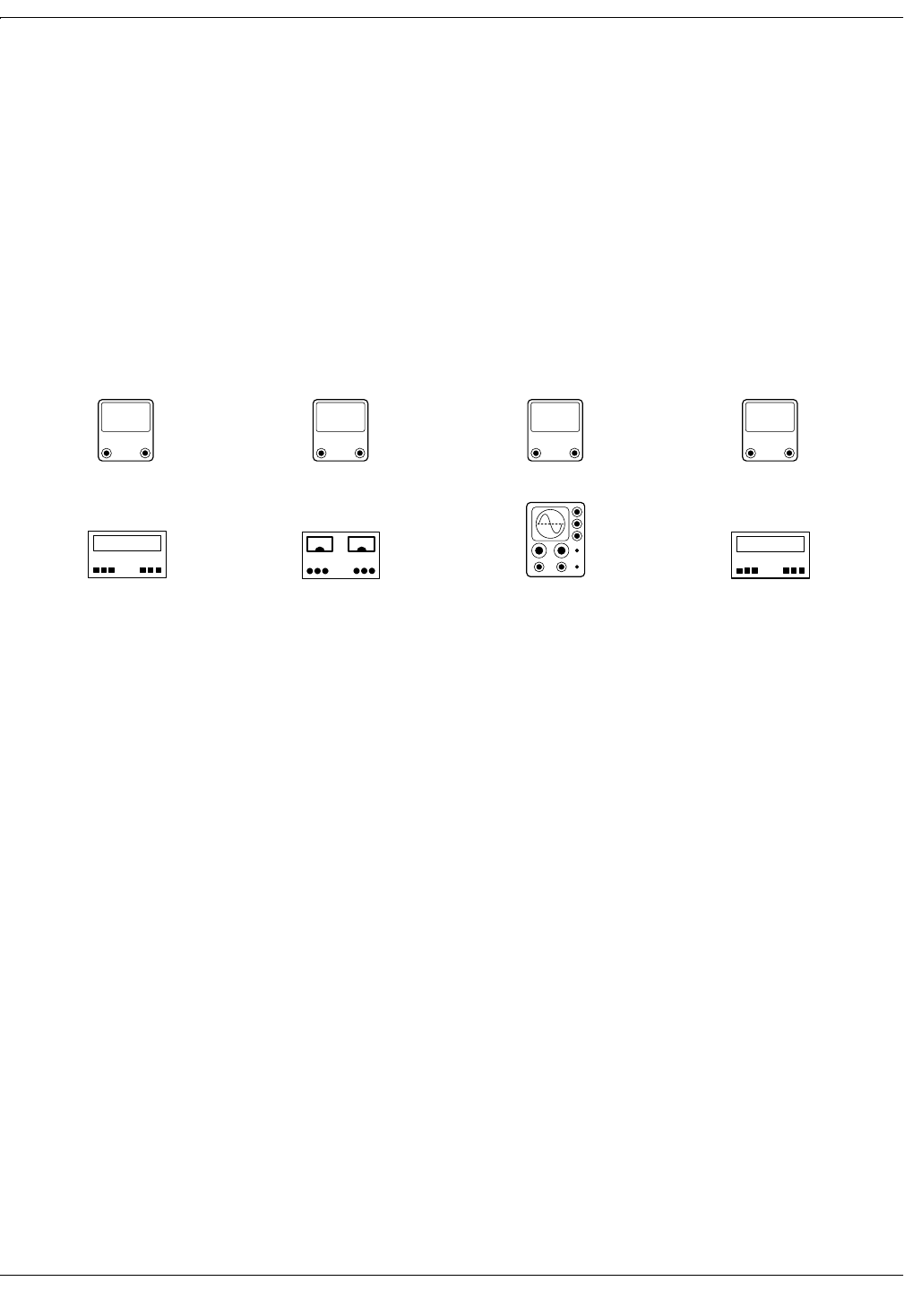
Test Equipment
Testing or calibrating the Model 340 requires the use of properly
calibrated, laboratory-class, test equipment. Although the generic
equivalents of the test equipment are given in this procedure, the actual
equipment selected must have specifications that substantially exceed
the tolerance given for each measurement.
Throughout this chapter, the calibration procedures are augmented by
icons representing the type of equipment each procedure requires.
Figure 5-1 summarizes the type of equipment represented by each icon.
Figure 5-1. Summary of Test Equipment
DC
AMPS
DC Ammeter
AC
VOLTS
AC RMS Voltmeter
888 888 888
Hz Counter
Frequency Counter
DC
VOLTS
DC Voltmeter
DC SUPPLY
↑
↑
DC Power Supply
dB
UNITS
dB Meter
888 888 888
Hz Generator
Frequency Generator
Oscilloscope

5-4 Model 340 Telemetry System Revision A
2006920-001
Calibration: Receiver Calibration
Receiver Calibration
Accessing the Receiver Board
When viewing the receiver from the top with its cover removed, the
Telemetry Receiver Board is located in the bottom section of the receiver
chassis. Accessing the Telemetry Receiver Board requires removal of the
top cover. To remove the board:
1. Remove the four receiver RF module mounting screws and
disconnect the cables. Do not disconnect the antenna wire that is
connected to the BNC connector. Remove the receiver module and
the four standoffs. Place the module to the side.
2. Remove the two screws securing the power transformer from the side
of the bracket and lay it to the side. Unplug the connector from the
transformer to the PC board.
3. Remove the three heat sink screws from the side of the case.
4. Unplug the front panel cables from the PC board. Disconnect the
ground wire from the front and rear panels.
5. Slide the front panel up and off the base; place it to the side.
6. Remove the six (6) PC board screws, (two (2) nuts per connector and
two (2) jacksockets) from the rear panel. Slide the PC board toward
the front as far as possible.
7. Slide the rear panel up and off, placing it to the side.
8. Slide the PC board out toward the rear, clearing the sides of the case
and taking care not to bend the heat sink.
When servicing the Telemetry Receiver Board, refer to the board’s
schematic and assembly drawing in Chapter 9 of this manual.

Revision A Model 340 Telemetry System 5-5
2006920-001
Calibration: Receiver Calibration
Power Supply
When checking the power supply voltages in this section, ensure all
voltage checks are within their allowable limits at both low and high AC
line voltages.
1. Refer to Table 5-1 and confirm the power supply voltages at the
indicated test points.
2. Confirm the voltage at TP27 is +12 ± 0.6 Vdc with the RF module
connected to J6.
3. Remove the four screws retaining the RF module. Unplug the
connector P6. Do not disconnect the antenna wire. Lay the module
outside the receiver chassis. This will allow access to all the
Telemetry Receiver Board test points and adjustments.
Ultrasound Channel
1. Connect the signal generator between J6 (2) and J6 (Gnd). Adjust the
signal generator for a signal level of 1.0Vp-p at TP45.
2. Confirm the –3 dB points of the band-pass frequency are at least 200
Hz and 400Hz from the input at TP45 to the output at TP14. Set R33
for a gain of 2 at the center of band-pass frequency.
DC
VOLTS
Table 5-1. Power Supply Voltages
Test Point Power Supply Voltage
TP23 +15 ± 0.6 Vdc
TP25 –15 ± 0.6 Vdc
TP26 +5 ± 0.3 Vdc
TP24 –5 ± 0.3 Vdc
dB
UNITS
AC
VOLTS 888 888 888
Hz Generator

5-6 Model 340 Telemetry System Revision A
2006920-001
Calibration: Receiver Calibration
TOCO Channel
1. Confirm the –3dB points of the band-pass frequency from the input
at TP45 to the output at TP29. The lower 3 dB point should measure
between 1250 and 1650 Hz. The upper 3 dB point should measure
between 1900 and 2250 Hz. The gain at TP29 is 2 at the center of the
bandpass.
2. With input frequency at TP45 set to 1750Hz and 250 mVp-p, adjust
R73 until the dc voltage at TP3 is equal to the dc voltage at
TP4 ± 10 mVdc.
3. With the input frequency switched between 1750 Hz and 1505 Hz,
adjust R89 for a voltage differential at TP20 of 4.14 ± 0.1 Vdc.
127(The low frequency response of this output stage is
approximately 0.1 Hz. Allow the stage time to settle between
frequency shifts. The scale factors for the TOCO stages are
27.2 mV/mm and 16.3 mV/Hz at TP20. Any input frequency
shifts can be used to achieve these scale factors.
4. Confirm frequency response at TP20 is dc to 0.1 ± 0.02Hz.
5. Confirm the PLL lock-in range. This is the frequency where it
first achieves lock, not the range over which it maintains lock.
PLL lock occurs at ≥1300 Hz and ≤2200Hz. Confirm lock occurs at
1300–1520 Hz and 1970–2420 Hz. Lock-in is verified by a logic low
at TP5.
dB
UNITS
AC
VOLTS
888 888 888
Hz Generator
888 888 888
Hz Counter

Revision A Model 340 Telemetry System 5-7
2006920-001
Calibration: Receiver Calibration
ECG Channel
1. Confirm the –3 dB points of the band-pass frequency are at least
2200 Hz and 3000 Hz between the input TP45 and the output TP17.
Confirm the filter gain of 2 at center frequency.
2. With input frequency set at 2700 Hz and 250 mVp-p at TP45,
adjust R106 until the dc voltage at TP10 is equal to the dc voltage at
TP46 ± 10 mVdc.
3. Sweep the input frequency between 2450 Hz and 2950 Hz at a rate of
approximately 25 Hz. Observe the 25 Hz waveform at TP19 with an
8 ± 1.6 Vp–p amplitude.
4. Confirm the PLL lock-in range. This is the frequency where it
first achieves lock, not the range over which it maintains lock.
PLL lock occurs at ≥2300Hz and ≤3100Hz. Confirm lock occurs at
2205–2450 Hz and2950–3245 Hz. Lock-in is verified by a logic low at
TP18.
5. Confirm the frequency response –3 dB points at TP19 are 5 and 50
Hz.
dB
UNITS
AC
VOLTS
888 888 888
Hz Generator
888 888 888
Hz Counter

5-8 Model 340 Telemetry System Revision A
2006920-001
Calibration: Receiver Calibration
Mode Controls
1. Confirm the low-pass filter –3 dB cutoff point of 90 ± 6Hz with an
input of 1.0 Vp-p at TP45 and the output at TP21. Set R61 for a gain
of 2.3.
2. Adjust R177 for a frequency of 8020 ± 20Hz at TP32.
3. Confirm a 10 ± 0.1 Vp-p, 4010 ± 20 Hz square wave at TP33.
4. Confirm the center frequency and the –3 dB points of the switched
capacitor bandpass filters for each IC listed in Table 5-2.
5. With no signal applied, adjust the tone decoders for the correct center
frequency indicated in Table 5-3.
dB
UNITS AC
VOLTS DC
VOLTS 888 888 888
Hz Generator
888 888 888
Hz Counter
Table 5-2. Band-Pass Filter Center Frequencies and –3 dB Points
IC Reference Center Frequency –3 dB Point
U17-6 80 Hz 75 Hz, 85 Hz
U18-6 40 Hz 35 Hz, 45 Hz
U23-6 20 Hz 15 Hz, 25 Hz
U27-6 10 Hz 5 Hz, 15 Hz
Table 5-3. Center Frequencies of Tone Decoders
Test Point Center Frequency Adjustment
TP6 10 Hz R95
TP8 20 Hz R99
TP9 40 Hz R110
RP11 80 Hz R149

Revision A Model 340 Telemetry System 5-9
2006920-001
Calibration: Receiver Calibration
6. Refer to Table 5-4. Confirm each tone decoder output locks. The
output will go to a logic low state when a 50 mVRMS sine wave of
proper frequency is applied to each input at pin 3 of each IC.
7. Ground TP18. Confirm TP30 goes to a low with the presence of the
20 Hz mode tone.
8. Remove the 20 Hz tone. Confirm TP31 goes to a low with presence of
2600Hz subcarrier only, with 1.0 Vp-p at TP 45.
RF Carrier Detect
1. Disconnect the UHF receiver module at J6. Connect the positive lead
of a 0 to +5 Vdc adjustable voltage source to J6 pin 3. Connect the
negative lead of the variable voltage source to J6 pin 5. Set R1 fully
clockwise (wiper at +5 Vdc). Set the variable voltage source to +2.0
Vdc. Observe the following: the signal indicator is off, and a high
signal is on J4 pin 3. Adjust R1 counter-clockwise until TP1 goes
low. Observe that the signal indicator flashes at approximately 1-
second intervals. Increase the voltage from the variable voltage
source until the signal indicator stops flashing and remains
illuminated. Confirm the voltage source is at +3.0 ± 0.45 Vdc.
127(R1 may need to be readjusted with the UHF receiver module
reconnected to J6.
2. Remove the voltage source while observing TP1. TP1 should go high
between 0.2 and 0.8 seconds after the voltage source is removed.
3. With TP1 low, confirm the weak battery indicator signal located on
J4, pin 5 flashes at approximately 1-second intervals with TP12 and
TP7 jumpered to ground. Confirm the indicator illuminates
continuously with only TP1 and TP12 low, and is off if TP1 or TP12 is
high.
Table 5-4. Tone Decoder Output Locks
Input
C Reference Input
Center Frequency and Voltage Output
Test Point
U26-3 10 Hz at 50 mVRMS TP7
U28-3 20 Hz at 50 mVRMS TP47
U14-3 40 Hz at 50 mVRMS TP48
U21-3 80 Hz at 50 mVRMS TP12
DC
VOLTS
DC SUPPLY
↑
↑

5-10 Model 340 Telemetry System Revision A
2006920-001
Calibration: Receiver Calibration
Mode Outputs
1. The mode output signals are generated via open collector transistor
switches in U2. For test purposes, the outputs must be connected to a
fetal monitor via the US, ECG and UA interconnect cables or pulled
up to +5 V (TP5) by 10kΩ resistors.
127(When testing the TOCO and IUP mode outputs, the receiver
front panel UA mode switch must be in the appropriate
position.
2. Refer to Table 5-3. Confirm operation of U2’s internal open collector
transistor switches. Correct operation is a closure to ground at the
connector pins indicated. The transistor switch will be open if either
control signal is high.
Pulsed Doppler Ultrasound Audio Converter
1. Feed a 1 Vp-p 300 ms burst of 300 Hz sine wave into J6 pin 2 (with
J6 pin 6 as reference); observe the waveform and its envelope at
TP14. Adjust the signal generator for an amplitude of 1.0 Vp-p at
TP14. With J201 pin 8 open, confirm the waveform at TP43
maintains the same envelope shape, but at half the frequency (150
Hz) as the signal at TP14. Confirm the peak-to-peak amplitude at
TP43 is equal to the amplitude at TP14 –0 + 0.6Vp-p.
2. Connect J201 pin 8 to ground and observe the waveforms at TP14
and TP43 are the same.
Table 5-5. Open Collector Transistor Switch Testing
Signal Name Control Signals Reference Points UA Mode Switch
USEN* TP1 and TP7 Low J201-11 and J10-12 —
MECGEN* TP1 and TP31 Low J202-4 and J10-10 —
FECGEN* TP1 and TP30 Low J202-2 and J10-3 Low —
TOCOEN* TP1 and TP5 Low J203-12 and J10-11 TOCO
IUPEN* TP1 and TP5 Low J203-11 and J10-13 IUP

Revision A Model 340 Telemetry System 5-11
2006920-001
Calibration: Receiver Calibration
Ultrasound Modulator
1. Connect a 3 Vp-p 2.3 MHz sine wave signal source into J201 pin 1.
Connect J201 pin 8 to ground. Feed a 300 Hz, 1 Vp-p sine wave into
J6 pin 2, and set R146 to its mid-position. Adjust L1 for maximum
output at TP13. L1 should go through a peak and drop off in
amplitude on either side of the peak setting.
2. Remove the 300 Hz source, adjust R146 for minimum output at
TP13. R146 should go through a null setting with the amplitude
rising at either side.
3. Remove the ground on J201 pin 8 and reconnect the 300 Hz signal
source. Change the frequency of the signal source on J201 pin-1 to
1.151 MHz and adjust L2 for maximum output at TP13. L2 should
go through a peak and drop off in amplitude on either side of the
peak setting.

5-12 Model 340 Telemetry System Revision A
2006920-001
Calibration: Transmitter Calibration
Transmitter Calibration
UA Channel
1. Connect the positive lead of a 0–4 V adjustable DC lab supply to J5
pin 1 (PRESS+) through a 100 KΩ resistor and the negative lead to
J5 pin 2 (PRESS–) and J5 pin 6 (GROUND). Jumper a 100 Ω resistor
across J5 pin 1 and J5 pin 2. Add a jumper between J5 pin 12 and J5
pin 7. Preset R197 fully counter-clockwise (maximum resistance),
and R196 to approximately the mid-adjustment point.
2. Connect a digital voltmeter to TP18. Adjust the DC lab supply for a
voltage at TP18 of 0 V ± 10 mV. Connect the frequency counter to
TP19 and preset R196 for a frequency of approximately 1.75 kHz.
Adjust the lab supply for a voltage of –4.000 Vdc ± 10 mV at TP18.
Adjust R197 for a frequency of approximately 1.5 kHz. Swap the
leads from the lab supply to J5 and adjust the supply for a voltage of
+4.000 V ± 10 mV at TP18. Readjust R196 for a frequency of
approximately 2.0 kHz. Repeat the above procedure until TP19
produces a frequency of 2.000 kHz ± 5 Hz with TP18 at +4.000 V ± 10
mV and a frequency of 1.500 kHz ± 5 Hz with TP18 at –4.000 V ± 10
mV.
ECG Channel
1. Connect a digital voltmeter to TP6. Connect the frequency counter to
TP20 and preset R193 for a frequency of approximately 2.7 kHz.
Connect the positive output of the 0–4V DC lab supply to connector
J3 pin 1 and the negative output of the supply to J3 pin 2. Add a
jumper between J6 pin 2 and J6 pin 3. Adjust the lab supply for a
voltage of –4.000 Vdc ± 10 mV at TP6. Adjust R194 for a frequency of
approximately 2.45 kHz.
2. Swap the input leads from the lab supply to J3 and adjust the supply
for a voltage of +4.000 V ± 10 mV at TP6. Readjust R193 for a
frequency of approximately 2.95 kHz. Repeat the above procedure
until TP20 produces a frequency of 2.950 kHz ± 5 Hz with TP6 at
+4.000 V ± 10 mV and a frequency of 2.450 kHz ± 5 Hz with TP6 at
–4.000 V ± 10 mV.

Revision A Model 340 Telemetry System 5-13
2006920-001
Calibration: Transmitter Calibration
Main Oscillator
Connect the frequency counter to TP7. Adjust C135 for a frequency of
4.604 MHz ± 5 Hz.
Power Supply
1. Confirm –5.6 V ± 0.2 V at TP11
2. Confirm +5.8 V ± 0.2 V at TP10
3. Confirm +5.0 V ± 0.25 V at TP16
4. Confirm +2.50 V ± 0.05 V at TP12
5. Confirm –2.50 V ± 0.05 V at TP14

5-14 Model 340 Telemetry System Revision A
2006920-001
For your notes

Revision A Model 340 Telemetry System 6-1
2006920-001
Chapter 6
Maintenance 6
All equipment, no matter how reliable, needs to be maintained on a
regular basis. This section describes general care and cleaning
instructions for the Model 340 Telemetry System.
General Cleaning Precautions. . . . . . . . . . . . . . . . . . . . . . . . 6-2
Cleaning the Transmitter and Receiver . . . . . . . . . . . . . . . . 6-3

6-2 Model 340 Telemetry System Revision A
2006920-001
Maintenance: General Cleaning Precautions
General Cleaning Precautions
127(Refer to your monitor’s
operator’s manual for cleaning
instructions for the monitor and
transducers.
&$87,21
SHOCK—Unplug the fetal or maternal/fetal monitor and
the Model 340R Receiver from the AC power source and
detach all accessories. Do not immerse accessories in any
liquid. Do not use abrasive cloth or cleaners on the
monitor, the Model 340R Receiver, the Model 340T
Transmitter, or any accessories.

Revision A Model 340 Telemetry System 6-3
2006920-001
Maintenance: Cleaning the Transmitter and Receiver
Cleaning the Transmitter and Receiver
1. Wipe any fluids from the surface of each unit.
2. Dampen a soft cloth with isopropyl alcohol and gently rub soiled area
until clean.
3. Dry with a soft, dry cloth.

6-4 Model 340 Telemetry System Revision A
2006920-001
For your notes

Revision A Model 340 Telemetry System 7-1
2006920-001
Chapter 7
Troubleshooting 7
This section of the manual provides a troubleshooting guide for the most
basic Model 340 operational problems. If the response to a specific
question is not found, contact the Service Department at one of the
following telephone numbers:
Inside the United States: Call 1-800-558-5120.
Outside the United States: Call 414-355-3790;
or contact your local distributor.

7-2 Model 340 Telemetry System Revision A
2006920-001
Troubleshooting: Problem Chart
Problem Chart
Table 7-1. Troubleshooting
Problem Probable Cause Solution
Receiver Power indicator does not light
when the receiver is turned on.
Receiver not connected to AC
receptacle.
Defective AC power cord.
Defective AC outlet.
Connect to AC receptacle.
Replace AC power cord.
Use a different AC outlet.
Signal indicator flashes with
transmitter turned on.
Transmitter batteries completely
discharged.
Mismatched transmitter and receiver
channels.
Replace batteries. Dispose of used
batteries according to the
manufacturer’s directions.
Ensure transmitter and receiver are
labeled with identical channel
numbers.
Signal indicator flashes
intermittently as patient
ambulates.
Patient outside signal transmission
range.
Metal in walls, doors, or other
structures between transmitter and
receiver.
Instruct patient to stay within signal
range and designated areas where
reception is clear.
Install optional ceiling antenna system.
Contact your Information Technologies
Service Representative.
Signal and Low Battery
indicators light with transmitter
turned off.
External source of radio frequency
interference is present.
Another transmitter with the same
frequency is in use within the same
facility.
Service required.
Contact your Information Technologies
Service Representative.
Discontinue use of one of the
transmitters. NOTE: Model 340 Plus
and Model 340M Telemetry Systems
can be factory re-programmed to an
alternative channel number.
Contact your Information Technologies
Service Representative.
Low Battery indicator flashes
with transducers plugged into
transmitter.
Transmitter batteries have less than 10
minutes of energy left.
Replace the batteries. Dispose of used
batteries according to the manufacturer’s
instructions.
Low Battery indicator lights
continuously with no
transducers plugged into
transmitter.
Transmitter batteries are depleted. Replace the batteries. Dispose of used
batteries according to the manufacturer’s
instructions.

Revision A Model 340 Telemetry System 7-3
2006920-001
Troubleshooting: Problem Chart
Erratic FHR/UA recording.
Transducer not properly placed.
Transducer not properly connected to
transmitter.
Receiver interconnection cable(s) not
properly attached.
Receiver interconnection cable(s)
defective.
Wrong interconnection cable(s) in use.
Radio frequency interference.
Another transmitter with the same
frequency is in use within the same
facility.
Exceeding transmission range.
Shielding effect of hospital structure.
Reposition transducer.
Ensure the transducer is securely
attached to the transmitter.
Ensure interconnection cable(s) firmly
attached to both monitor and receiver.
Replace interconnection cable(s).
Verify interconnection method.
Instruct patient to stay within signal
range and designated areas where
reception is clear.
Discontinue use of one of the
transmitters. NOTE: Model 340 Plus
and Model 340M Telemetry Systems
can be factory re-programmed to an
alternative channel number.
Install optional ceiling antenna system.
Contact your Information Technologies
Service Representative.
Monitor FHR and UA displays do not light
when transducers are plugged into
transmitter.
Monitor, transmitter, and/or receiver
off.
Receiver interconnection cable(s) not
properly attached.
Receiver interconnection cable(s)
defective.
Wrong interconnection cable(s) in use.
Ensure all three devices are turned on.
Ensure interconnection cable(s) firmly
attached to both monitor and receiver.
Replace interconnection cable(s).
Verify interconnection method.
Transmitter “chirps” every 4–5 seconds. Transmitter batteries have less than 10
minutes of energy left.
Replace the batteries. Dispose of used
batteries according to the manufacturer’s
instructions.
Table 7-1. Troubleshooting (Continued)
Problem Probable Cause Solution

7-4 Model 340 Telemetry System Revision A
2006920-001
For your notes

Revision A Model 340 Telemetry System 8-1
2006920-001
Chapter 8
Technical Specifications8
127(Specifications are subject
to change without notice. This section contains a detailed list of the technical specifications for the
Model 340 Telemetry System.
This chapter lists specifications for the following:
Transmitter . . . . . . . . . . . . . . . . . . . . . . . . . . . . . . . . . . . . . . 8-2
Receiver. . . . . . . . . . . . . . . . . . . . . . . . . . . . . . . . . . . . . . . . . . 8-4

8-2 Model 340 Telemetry System Revision A
2006920-001
Technical Specifications: Transmitter
Transmitter
Table 8-1. Transmitter
Category Technical Specifications
Physical Characteristics
Height:
Width:
Depth:
Weight:
1.8 in (4.5 cm)
5.4 in (13.8 cm)
7.5 in (19.0 cm)
1.75 lbs (0.8 kg)
Environmental Conditions
Ambient Temperature:
Relative Humidity:
Atmospheric Pressure:
Operating Storage
50°F to 104°F (10°C to 40°C) 14°F to 131°F (–10°C to 55°C)
5% to 95%, non-condensing 5% to 95%, non-condensing
700–1060 mbar (525–795 mmHg) 700–1060 mbar (525–795 mmHg)
Certification and Compliance
UL:
FCC:
Industry Canada:
340 Original Release and Plus 340M
UL-544 Listed UL-544 Listed
Complies with FCC Part 90 Complies with FCC Part 95
Complies with RSS-119 Complies with RSS-210
Monitoring Modes
Fetal Heart Rate:
Uterine Activity:
Maternal Heart Rate:
Ultrasound (US) and Fetal ECG (FECG)
External Tocotransducer (TOCO) or Internal Intrauterine Pressure Catheter (IUPC)
Maternal ECG (MECG)
Ultrasound Mode
System:
Transmitter Frequency:
Intensity (Isata):
Pulse Doppler
1.151 MHz
<5 mW/cm2
ECG Mode
Input Impedance:
dc Tolerance:
Common Mode Rejection Ratio:
FECG Sensitivity:
MECG Sensitivity:
>1 GΩ
±1 V
>90 dB
20 µV to 1 mV
0.5 mV to 5 mV
TOCO Mode
Type:
Sensitivity:
Range:
Tocotransducer
20 µV/relative unit
–50 to +250 relative units
IUPC Mode
Type:
Sensitivity:
Range:
dc Strain Gauge
20 µV/mmHg
–50 to +250 mmHg
RF Section
Output Power:
Available Frequencies:
Channel Bandwidth:
340 Original Release and Plus 340M
10 mW 4 mW
430–470 MHz 608–614 MHz
25 kHz 25 kHz
Transmission Range: 340 Original Release and Plus 340M
1640 ft (500 m), line of sight 200 ft (61 m), line of sight

Revision A Model 340 Telemetry System 8-3
2006920-001
Technical Specifications: Transmitter
Antenna Type: Flexible, detachable, BNC interconnect
Batteries
Type:
Life: Four “AA” Alkaline Cells, 6.0 Vdc at 2450 mAh
20 h, approximatelya
Control: On/Off Switch
Audio Indicator: Low Battery
Connectors: Remote Event Marker Input, Headset Output
aUse of the headset will deplete the batteries more rapidly.
Table 8-1. Transmitter
Category Technical Specifications

8-4 Model 340 Telemetry System Revision A
2006920-001
Technical Specifications: Receiver
Receiver
Table 8-1. Receiver
Category Technical Specifications
Power Requirements
Nominal Line Voltage:
Line Frequency:
Power Consumption (maximum):
Chassis Leakage:
100–120 VAC 220–240 VAC
50/60 Hz 50/60 Hz
30 W 30 W
<50 µA
Physical Characteristics
Height:
Width:
Depth:
Weight:
3.2 in (8.1 cm)
7.4 in (18.8 cm)
11.4 in (29.0 cm)
7.0 lbs (3.2 kg)
Environmental Conditions
Ambient Temperature:
Relative Humidity:
Atmospheric Pressure:
Operating Storage
50°F to 104°F (10°C to 40°C) 14°F to 131°F (–10°C to 55°C)
5% to 95%, non-condensing 5% to 95%, non-condensing
700–1060 mbar (525–795 mmHg) 700–1060 mbar (525–795 mmHg)
Certification and Compliance
UL:
FCC:
Industry Canada:
340 Original Release and Plus 340M
UL-544 Listed UL-544 Listed
Complies with FCC Part 15 Complies with FCC Part 15
Complies with RSS-119 Complies with RSS-210
Output Signals: US, ECG, UA, and Mark
RF Section
Input Impedance:
Input Sensitivity: 50 Ω
<0.4 µV for 12 dB SINAD
Antenna Type: Flexible, detachable, BNC interconnect
(Other factory-approved external antennas or antenna systems may be used. Contact
your Information Technologies Service Representative for more information.)
Controls: On/Off Switch, UA Mode Switch
Visual Indicators:
Power:
Signal Strength:
Transmitter Low/Depleted Battery:
Green LED
Green LED
Red LED
Connectors
AC Line Input:
Mark Output:
Ultrasound Output:
ECG Output:
UA Output:
Auxiliary Output:
3-Prong, IEC-Style
Use only with Models 115, 116, 118, 145, 150, 151, and 155 Monitors.
Use only with Models 115, 116, 118, 145, 150, 151, and 155 Monitors.
Use only with Models 115, 116, 118, 145, 150, 151, and 155 Monitors.
Use only with Models 115, 116, 118, 145, 150, 151, and 155 Monitors.
Use only with Series 120 and 170 Monitors.

Revision A Model 340 Telemetry System 9-1
2006920-001
Chapter 9
Drawings 9
This section of the manual provies the Model 340 schematics and
assembly drawings. These drawings should be used in conjunction with
other sections in this manual.

9-2 Model 340 Telemetry System Revision A
2006920-001
For your notes
MANUAL P/N 2006920-001 REV
A
Ê2006920-001ÅŠ