HARRIS TR-0017-E Sitepro Base Station User Manual Power Supply
HARRIS CORPORATION Sitepro Base Station Power Supply
UserManual.wiki
>
HARRIS
>
TR-0017-E User Manual
>
Power Supply
Contents
1.
Applications Diagrams
2.
Interface Panels
3.
Main Manual
4.
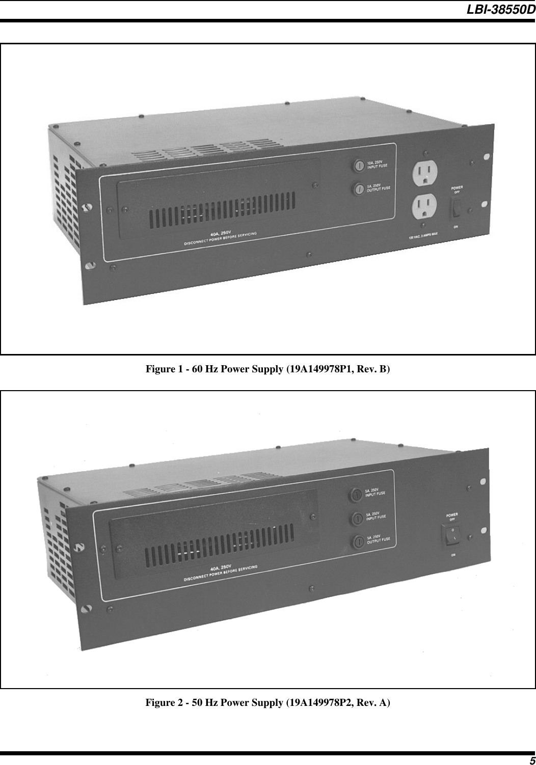
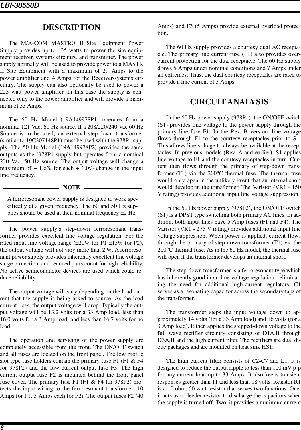
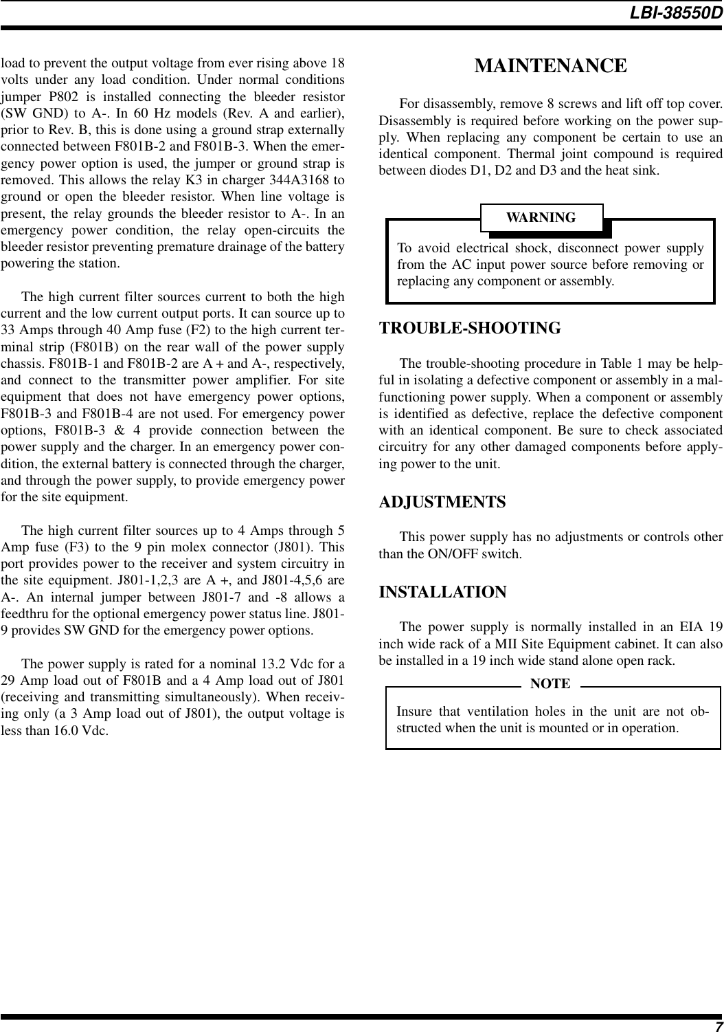
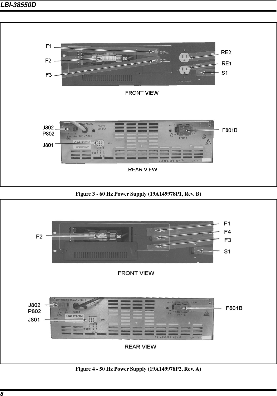
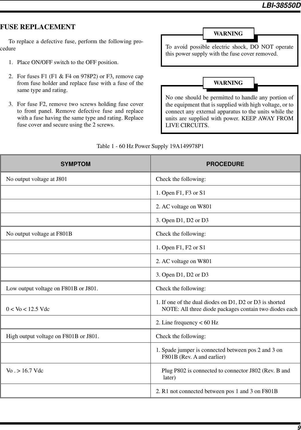
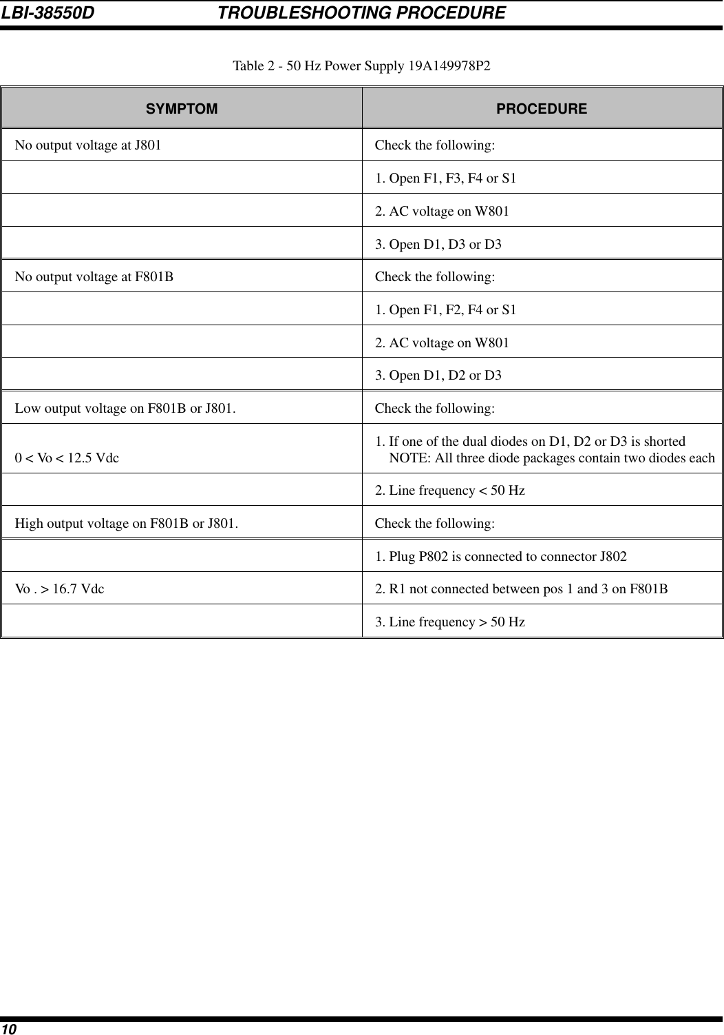
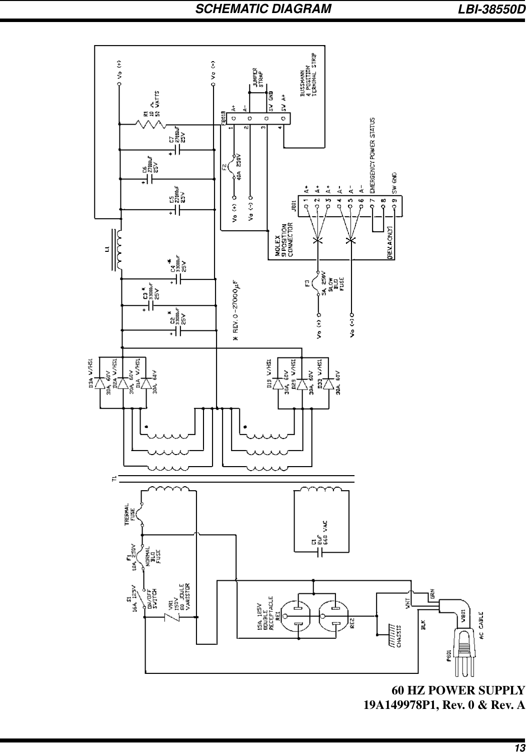
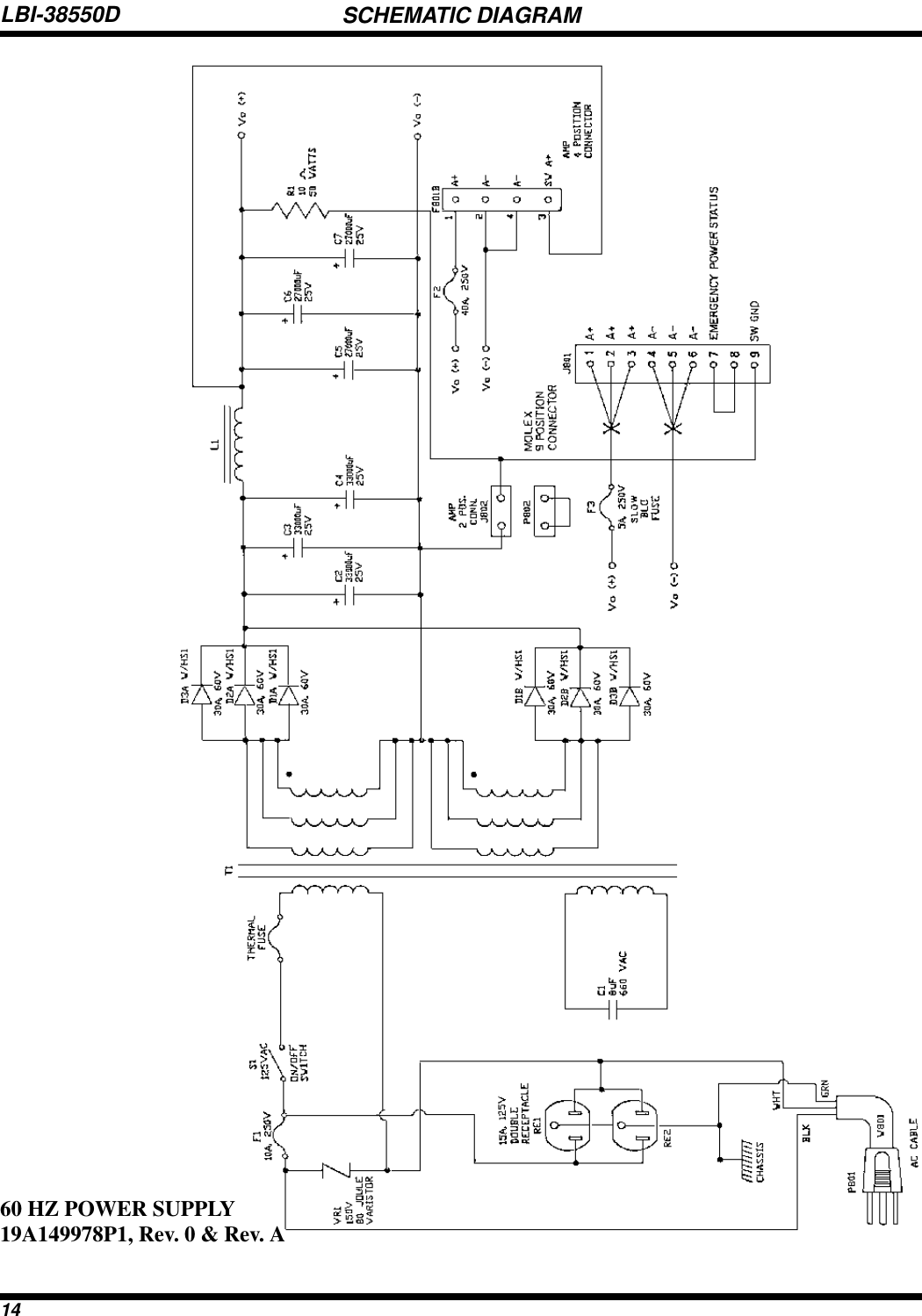
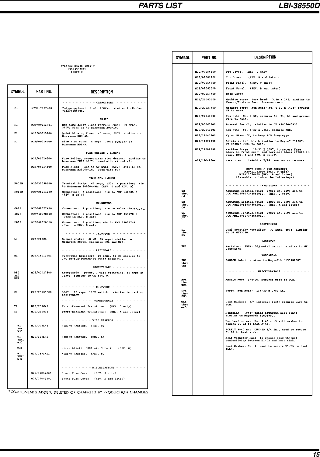
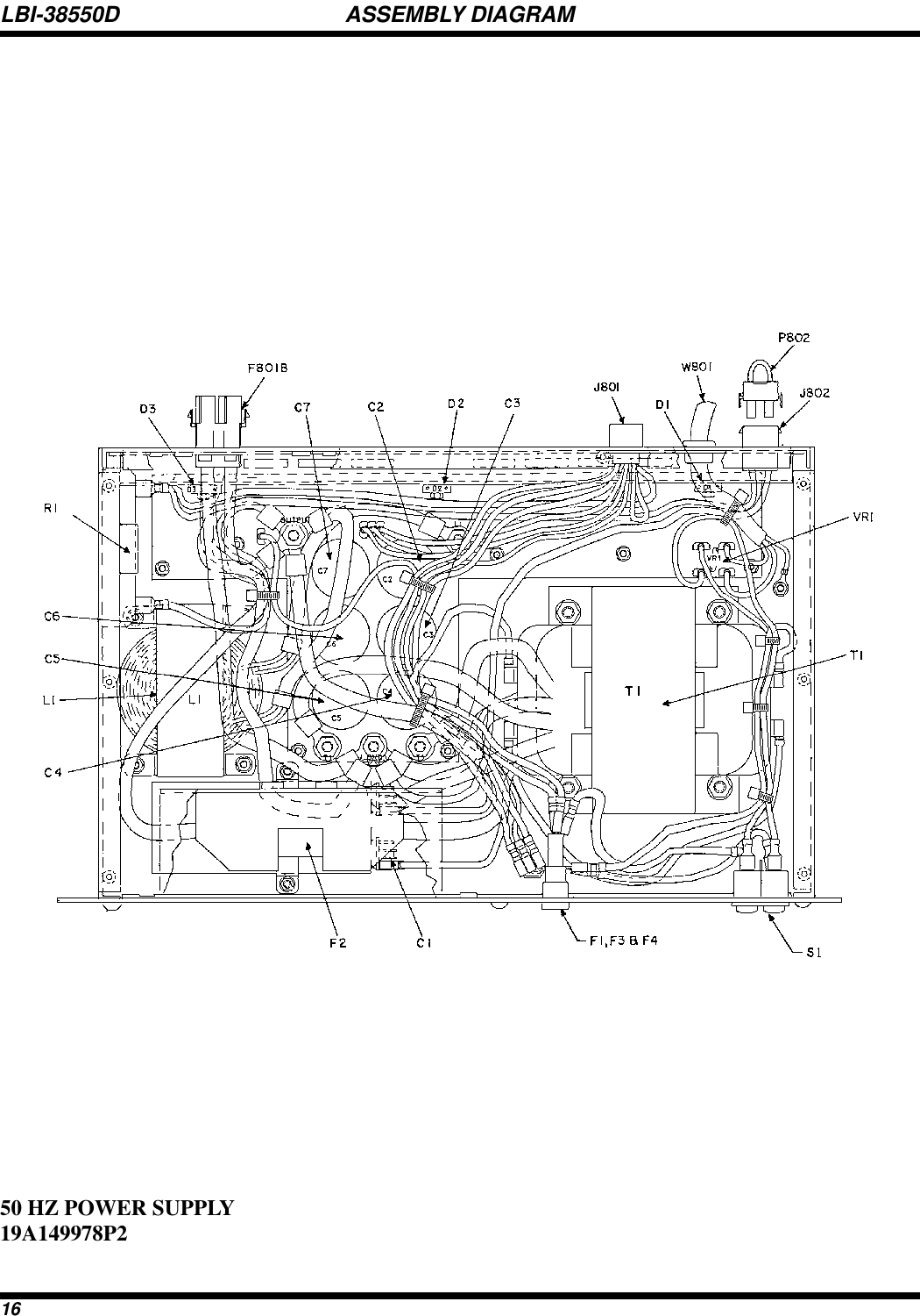
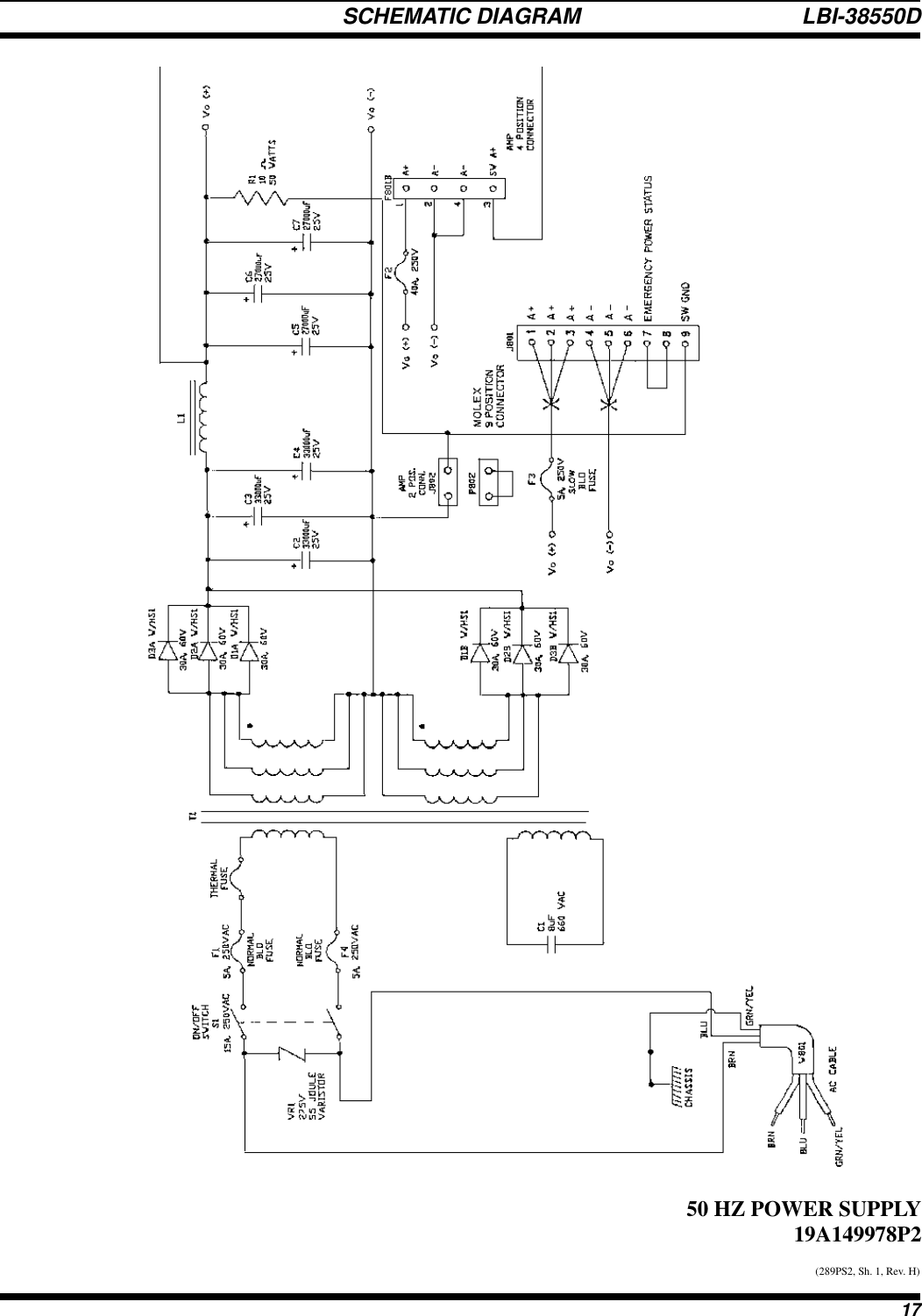
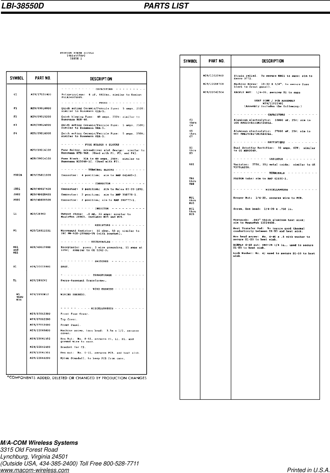
Power Supply
5.
RX IF
6.
RX Synth
7.
TX Synth
8.
RF Package
9.
Site Pro Manual Part 1
10.
Site Pro Manual Part 2
Power Supply
Navigation menu
Upload a User Manual
Namespaces
Wiki Guide
HTML
PDF
Info
Views
User Manual
Discussion / Help
Navigation