HARRIS TR-0017-E Sitepro Base Station User Manual Power Supply
HARRIS CORPORATION Sitepro Base Station Power Supply
HARRIS >
Contents
Power Supply
Maintenance Manual
LBI-38550D
Site Equipment Power Supply
19A149978P1 - 120 VOLT/60 Hz
19A149978P2 - 230 VOLT/50 Hz
THESE SERVICING INSTRUCTIONS ARE FOR USE BY QUALIFIED
PERSONNEL ONLY. TO AVOID ELECTRIC SHOCK DO NOT PERFORM
ANY SERVICING OTHER THAN THAT CONTAINED IN THE OPERATING
INSTRUCTIONS UNLESS YOU ARE QUALIFIED TO DO SO. REFER ALL
SERVICING TO QUALIFIED SERVICE PERSONNEL.
CAUTION
WARNING: TO PREVENT FIRE OR ELECTRIC SHOCK HAZARD.
DO NOT EXPOSE THIS PRODUCT TO RAIN OR MOISTURE.
CAUTION:
TO PREVENT ELECTRIC SHOCK DO NOT USE THIS (POLARIZED)
PLUG WITH AN EXTENSION CORD, RECEPTACLE OR OTHER OUTLET
UNLESS THE BLADES CAN BE FULLY INSERTED TO PREVENT BLADE
EXPOSURE.

Copyright© 1990 - 2002 M/A-COM Private Radio Systems, Inc. All rights reserved.
TABLE OF CONTENTS
Page
SPECIFICATIONS . . . . . . . . . . . . . . . . . . . . . . . . . . . . . . . . . . . . . . . . . . . . . . . . . 3
IMPORTANT SAFETY INFORMATION . . . . . . . . . . . . . . . . . . . . . . . . . . . . . . . . . . . . . 4
DESCRIPTION . . . . . . . . . . . . . . . . . . . . . . . . . . . . . . . . . . . . . . . . . . . . . . . . . . . 6
CIRCUIT ANALYSIS . . . . . . . . . . . . . . . . . . . . . . . . . . . . . . . . . . . . . . . . . . . . . . . . 6
MAINTENANCE . . . . . . . . . . . . . . . . . . . . . . . . . . . . . . . . . . . . . . . . . . . . . . . . . . 7
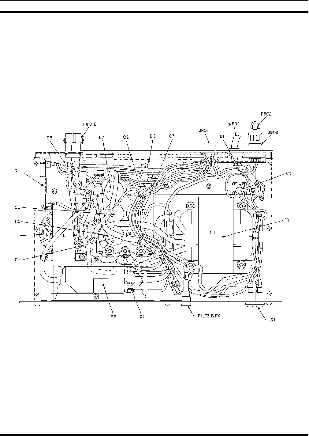
OUTLINE DIAGRAM . . . . . . . . . . . . . . . . . . . . . . . . . . . . . . . . . . . . . . . . . . . . . . . 11
ASSEMBLY DIAGRAMS
60 Hz Power Supply . . . . . . . . . . . . . . . . . . . . . . . . . . . . . . . . . . . . . . . . . . . . . 12
50 Hz Power Supply . . . . . . . . . . . . . . . . . . . . . . . . . . . . . . . . . . . . . . . . . . . . . 16
SCHEMATIC DIAGRAMS
60 Hz Power Supply . . . . . . . . . . . . . . . . . . . . . . . . . . . . . . . . . . . . . . . . . . . . . 13
50 Hz Power Supply . . . . . . . . . . . . . . . . . . . . . . . . . . . . . . . . . . . . . . . . . . . . . 17
PART LISTS
60 Hz Power Supply . . . . . . . . . . . . . . . . . . . . . . . . . . . . . . . . . . . . . . . . . . . . . . 15
50 Hz Power Supply . . . . . . . . . . . . . . . . . . . . . . . . . . . . . . . . . . . . . . . . . . . . . 18
SAFETY NOTES
•The means of disconnecting power from a station cabinet is the cabinet power supply plug.
•When conducting repair/maintenance, disconnect the cabinet power supply plug from the AC source.
•In European applications, equipment must be installed in a closed cabinet.
•Only replace components with components specified by M/A-COM Private Radio Systems.
Repairs to this equipment should be made only by an authorized service technician or facility designated by the supplier.
Any repairs, alterations or substitution of recommended parts made by the user to this equipment not approved by the
manufacturer could void the user’s authority to operate the equipment in addition to the manufacturer’s warranty.
NOTICE!
This manual is published by M/A-COM Private Radio Systems, Inc., without any warranty. Improvements and changes to
this manual necessitated by typographical errors, inaccuracies of current information, or improvements to programs and/or
equipment, may be made by M/A-COM Private Radio Systems, Inc., at any time and without notice. Such changes will
be incorporated into new editions of this manual. No part of this manual may be reproduced or transmitted in any form or by
any means, electronic or mechanical, including photocopying and recording, for any purpose, without the express written
permission of M/A-COM Private Radio Systems, Inc.
The software contained in this device is copyrighted by M/A-COM Private Radio Systems, Inc. Unpublished rights are
reserved under the copyright laws of the United States.
NOTICE!
LBI-38550D
2

SPECIFICATIONS*
OUTPUT VOLTAGE
Transmit and Receive Simultaneously 13.2 Vdc ±0.6 Vdc @ 29 Amps (F801B)
13.2 Vdc ±0.6 Vdc @ 4 Amps (J801)
Receive only < 16.0 Vdc @ 3 Amps (J801)
Transmit only
(For 225 watt PA option) 13.2 Vdc ±0.6 Vdc @ 33 Amps (F801B)
INPUT VOLTAGE 121 Vac ±20% (60 Hz version)
230 Vac ±15% (50 Hz version)
INPUT FREQUENCY 60 Hz ±2 Hz (60 Hz version)
50 Hz ±2 Hz (50 Hz version)
Note: For every + 1.0% change in the input frequency, the output voltage will not vary more than + 1.6% from the
output voltage measured at the nominal input line frequency.
INPUT LINE SURGE PROTECTION 150 V rated MOV (60 Hz version)
275 V rated MOV (50 Hz version)
DUTY CYCLE
For 0-33 Amp output 100% (Continuous Duty)
OUTPUT VOLTAGE RIPPLE < 100 mV p-p @ 25°C
< 200 mV p-p @ -30°C
OUTPUT TRANSIENT RESPONSE
Overshoot
Undershoot Not to exceed 18 Volts
Not less than 11 Volts
EFFICIENCY > 70% @ rated TX/RX load current and nominal line volt-
age
FUSE CAPABILITY
Input 10 Amp (60 Hz version)
(2) 5 Amp (50 Hz version)
Output 5 Amp (Low Current Port)
40 Amp (High Current Port)
DIMENSIONS (HxWxD) 5.25" x 19" x 10.35"
WEIGHT 45 lbs.
OPERATING ENVIRONMENT -30°C To +60°C
*These specifications are intended primarily for the use of the service personnel. Refer to the appropriate Specification
Sheet for the complete specifications.
LBI-38550D
3

1. SAVE THIS MANUAL - It contains important safety
and operating instructions.
2. Before using the product, please follow and adhere to
all warnings, safety and operating instructions located
on the product and in the manual.
3. DO NOT expose product to rain, snow or other type of
moisture.
4. Care should be taken so objects do not fall or liquids do
not spill into the product.
5. DO NOT expose product to extreme temperatures.
6. DO NOT use auxiliary equipment not recommended or
sold by the manufacturer. To do so may result in a risk
of fire, electric shock or injury to persons.
7. To reduce risk of damage to electrical cord, pull by plug
rather than cord when disconnecting unit.
8. Make sure the cord is located so it will not be stepped
on, tripped over or otherwise subjected to damage or
stress.
9. An extension cord should not be used unless absolutely
necessary. Use of an improper extension cord could re-
sult in a risk of fire and electric shock. If an extension
cord must be used, make sure:
a. That pins on the plug of the extension cord are the
same number, size and shape as those of the plug on
the power supply.
b. That the extension cord is properly wired in good
condition.
c. That the wire size is large enough for AC ampere rat-
ing of unit.
10. DO NOT operate unit with a damaged cord or plug. Re-
place the damaged cord immediately.
11. DO NOT operate this product in an explosive atmos-
phere unless it has been specifically certified for such
operation.
12. To reduce risk of electric shock, unplug unit from outlet
before attempting any maintenance or cleaning.
13. DO NOT operate this product with covers or panels re-
moved.This unit does not contain any user serviceable
components.
14. Use only fuses of the correct type, voltage rating and
current rating as specified in the parts list. Failure to do
so can result in fire hazard.
15. GROUNDING AND AC POWER CORD CON-
NECTION - To reduce risk of electrical shock use only
a properly grounded outlet. The unit is equipped with
an electric cord having an equipment - grounding con-
ductor and a grounding plug. Be sure the outlet is prop-
erly installed and grounded in accordance with all local
codes and ordinances.
16. DANGER - Never alter the AC cord or plug. Plug into
an outlet properly wired by a qualified electrician. Im-
proper connection or loss of ground connection can re-
sult in risk of an electrical shock.
17. The Model 19A149978P2 is for use on a circuit having
a nominal rating of 230 Vac and is factory equipped
with a specific electric cord to permit connection to an
acceptable electric circuit. A plug meeting local electri-
cal codes must be supplied by the customer. Make sure
the unit is connected to an outlet having the same con-
figuration as the plug. No adapter should be used with
this unit.
IMPORTANT SAFETY INFORMATION
A ferroresonant power supply is designed to work spe-
cifically at a given frequency. The 60 and 50 Hz sup-
plies should be used at their nominal frequency ±2 Hz.
NOTE
LBI-38550D
4
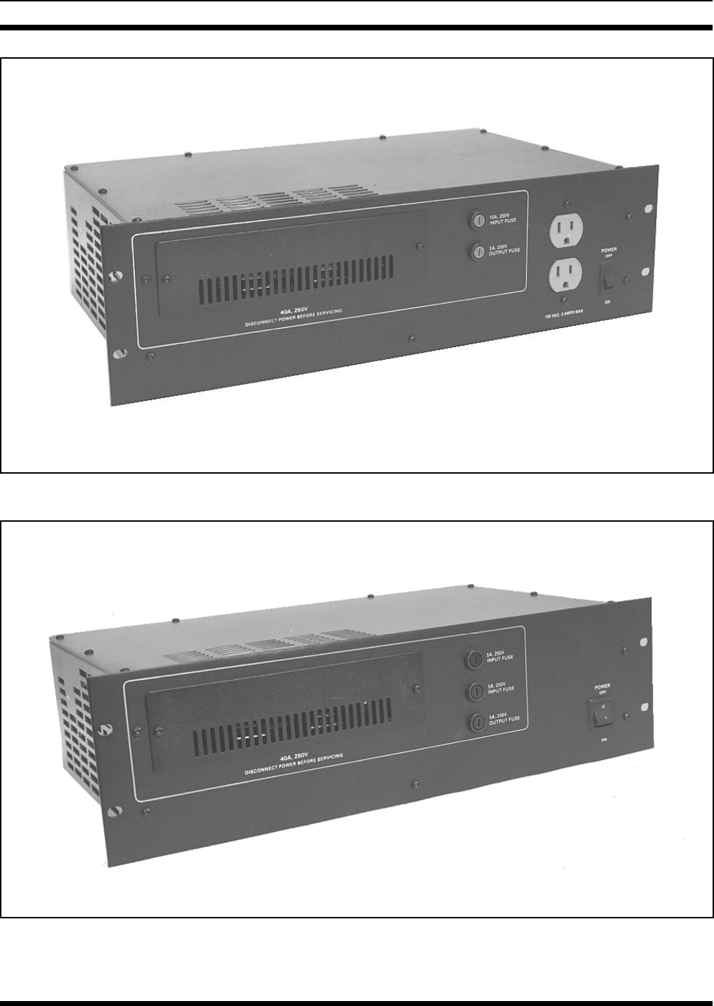
Figure 1 - 60 Hz Power Supply (19A149978P1, Rev. B)
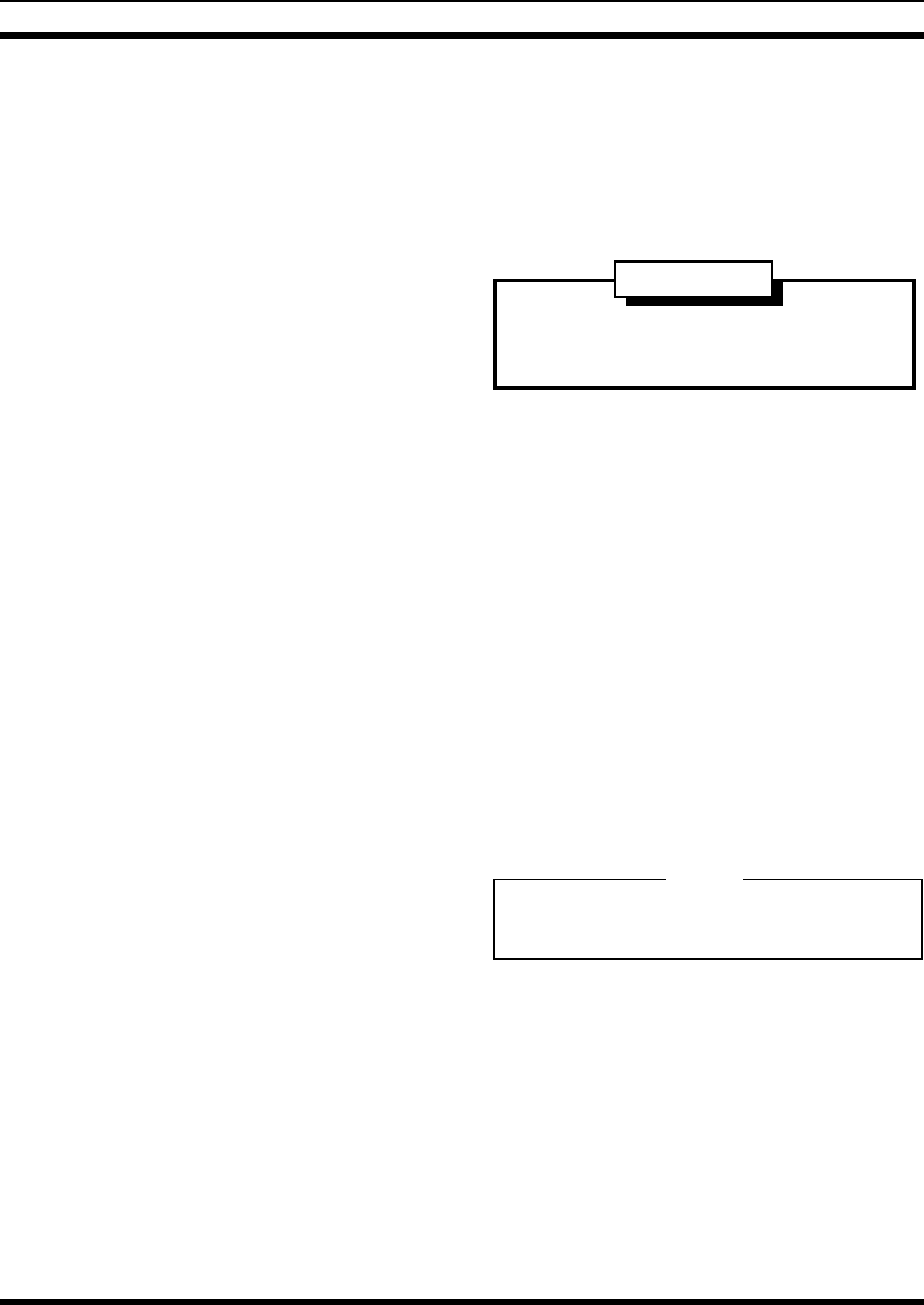
Figure 2 - 50 Hz Power Supply (19A149978P2, Rev. A)
LBI-38550D
5

DESCRIPTION
The M/A-COM MASTR II Site Equipment Power
Supply provides up to 435 watts to power the site equip-
ment receiver, systems circuitry, and transmitter. The power
supply normally will be used to provide power to a MASTR
II Site Equipment with a maximum of 29 Amps to the
power amplifier and 4 Amps for the Receiver/systems cir-
cuitry. The supply can also optionally be used to power a
225 watt power amplifier. In this case the supply is con-
nected only to the power amplifier and will provide a maxi-
mum of 33 Amps.
The 60 Hz Model (19A149978P1) operates from a
nominal 121 Vac, 60 Hz source. If a 208/220/240 Vac 60 Hz
Source is to be used, an external step-down transformer
(similar to 19C307148P1) must be used with the 978P1 sup-
ply. The 50 Hz Model (19A149978P2) provides the same
outputs as the ’978P1 supply but operates from a nominal
230 Vac, 50 Hz source. The output voltage will change a
maximum of + 1.6% for each + 1.0% change in the input
line frequency.
The power supply’s step-down ferroresonant trans-
former provides excellent line voltage regulation. For the
rated input line voltage range (±20% for P1 ±15% for P2),
the output voltage will not vary more than 2 %. A ferroreso-
nant power supply provides inherently excellent line voltage
surge protection, and reduced parts count for high reliability.
No active semiconductor devices are used which could re-
duce reliability.
The output voltage will vary depending on the load cur-
rent that the supply is being asked to source. As the load
current rises, the output voltage will drop. Typically the out-
put voltage will be 13.2 volts for a 33 Amp load, less than
16.0 volts for a 3 Amp load, and less than 16.7 volts for no
load.
The operation and servicing of the power supply are
completely accessible from the front. The ON/OFF switch
and all fuses are located on the front panel. The low profile
slot type fuse holders contain the primary fuse F1 (F1 & F4
for 978P2) and the low current output fuse F3. The high
current output fuse F2 is mounted behind the front panel
fuse cover. The primary fuse F1 (F1 & F4 for 978P2) pro-
tects the input wiring to the ferroresonant transformer (10
Amps for P1, 5 Amps each for P2). The output fuses F2 (40
Amps) and F3 (5 Amps) provide external overload protec-
tion.
The 60 Hz supply provides a courtesy dual AC recepta-
cle. The primary line current fuse (F1) also provides over-
current protection for the dual receptacle. The 60 Hz supply
draws 5 Amps under nominal conditions and 7 Amps under
all extremes. Thus, the dual courtesy receptacles are rated to
provide a line current of 3 Amps.
CIRCUIT ANALYSIS
In the 60 Hz power supply (978P1), the ON/OFF switch
(S1) provides line voltage to the power supply through the
primary line fuse F1. In the Rev. B version, line voltage
flows through F1 to the courtesy receptacles prior to S1.
This allows line voltage to always be available at the recep-
tacles. In previous models (Rev. A and earlier), S1 applies
line voltage to F1 and the courtesy receptacles in turn. Cur-
rent then flows through the primary of step-down trans-
former (T1) via the 200°C thermal fuse. The thermal fuse
would only open in the unlikely event that an internal short
would develop in the transformer. The Varistor (VR1 - 150
V rating) provides additional input line voltage suppression.
In the 50 Hz power supply (978P2), the ON/OFF switch
(S1) is a DPST type switching both primary AC lines. In ad-
dition, both input lines have 5 Amp fuses (F1 and F4). The
Varistor (VR1 - 275 V rating) provides additional input line
voltage suppression. When power is applied, current flows
through the primary of step-down transformer (T1) via the
200°C thermal fuse. As in the 60 Hz model, the thermal fuse
will open if the transformer develops an internal short.
The step-down transformer is a ferroresonant type which
has inherently good input line voltage regulation - eliminat-
ing the need for additional high-current regulators. C1
serves as a resonating capacitor across the secondary taps of
the transformer.
The transformer steps the input voltage down to ap-
proximately 14 volts (for a 33 Amp load) and 16 volts (for a
3 Amp load). It then applies the stepped-down voltage to the
full wave rectifier circuitry consisting of D1A,B through
D3A,B and the high current filter. The rectifiers are dual di-
ode packages and are mounted on heat sink HS1.
The high current filter consists of C2-C7 and L1. It is
designed to reduce the output ripple to less than 100 mV p-p
for any current load up to 33 Amps. It also keeps transient
responses greater than 11 and less than 18 volts. Resistor R1
is a 10 ohm, 50 watt resistor that serves two functions. One,
it acts as a bleeder resistor to discharge the capacitors when
the supply is turned off. Two, it provides a minimum current
A ferroresonant power supply is designed to work spe-
cifically at a given frequency. The 60 and 50 Hz sup-
plies should be used at their nominal frequency ±2 Hz.
NOTE
LBI-38550D
6
load to prevent the output voltage from ever rising above 18
volts under any load condition. Under normal conditions
jumper P802 is installed connecting the bleeder resistor
(SW GND) to A-. In 60 Hz models (Rev. A and earlier),
prior to Rev. B, this is done using a ground strap externally
connected between F801B-2 and F801B-3. When the emer-
gency power option is used, the jumper or ground strap is
removed. This allows the relay K3 in charger 344A3168 to
ground or open the bleeder resistor. When line voltage is
present, the relay grounds the bleeder resistor to A-. In an
emergency power condition, the relay open-circuits the
bleeder resistor preventing premature drainage of the battery
powering the station.
The high current filter sources current to both the high
current and the low current output ports. It can source up to
33 Amps through 40 Amp fuse (F2) to the high current ter-
minal strip (F801B) on the rear wall of the power supply
chassis. F801B-1 and F801B-2 are A + and A-, respectively,
and connect to the transmitter power amplifier. For site
equipment that does not have emergency power options,
F801B-3 and F801B-4 are not used. For emergency power
options, F801B-3 & 4 provide connection between the
power supply and the charger. In an emergency power con-
dition, the external battery is connected through the charger,
and through the power supply, to provide emergency power
for the site equipment.
The high current filter sources up to 4 Amps through 5
Amp fuse (F3) to the 9 pin molex connector (J801). This
port provides power to the receiver and system circuitry in
the site equipment. J801-1,2,3 are A +, and J801-4,5,6 are
A-. An internal jumper between J801-7 and -8 allows a
feedthru for the optional emergency power status line. J801-
9 provides SW GND for the emergency power options.
The power supply is rated for a nominal 13.2 Vdc for a
29 Amp load out of F801B and a 4 Amp load out of J801
(receiving and transmitting simultaneously). When receiv-
ing only (a 3 Amp load out of J801), the output voltage is
less than 16.0 Vdc.
MAINTENANCE
For disassembly, remove 8 screws and lift off top cover.
Disassembly is required before working on the power sup-
ply. When replacing any component be certain to use an
identical component. Thermal joint compound is required
between diodes D1, D2 and D3 and the heat sink.
TROUBLE-SHOOTING
The trouble-shooting procedure in Table 1 may be help-
ful in isolating a defective component or assembly in a mal-
functioning power supply. When a component or assembly
is identified as defective, replace the defective component
with an identical component. Be sure to check associated
circuitry for any other damaged components before apply-
ing power to the unit.
ADJUSTMENTS
This power supply has no adjustments or controls other
than the ON/OFF switch.
INSTALLATION
The power supply is normally installed in an EIA 19
inch wide rack of a MII Site Equipment cabinet. It can also
be installed in a 19 inch wide stand alone open rack.
Insure that ventilation holes in the unit are not ob-
structed when the unit is mounted or in operation.
NOTE
To avoid electrical shock, disconnect power supply
from the AC input power source before removing or
replacing any component or assembly.
To avoid electrical
WARNING
LBI-38550D
7
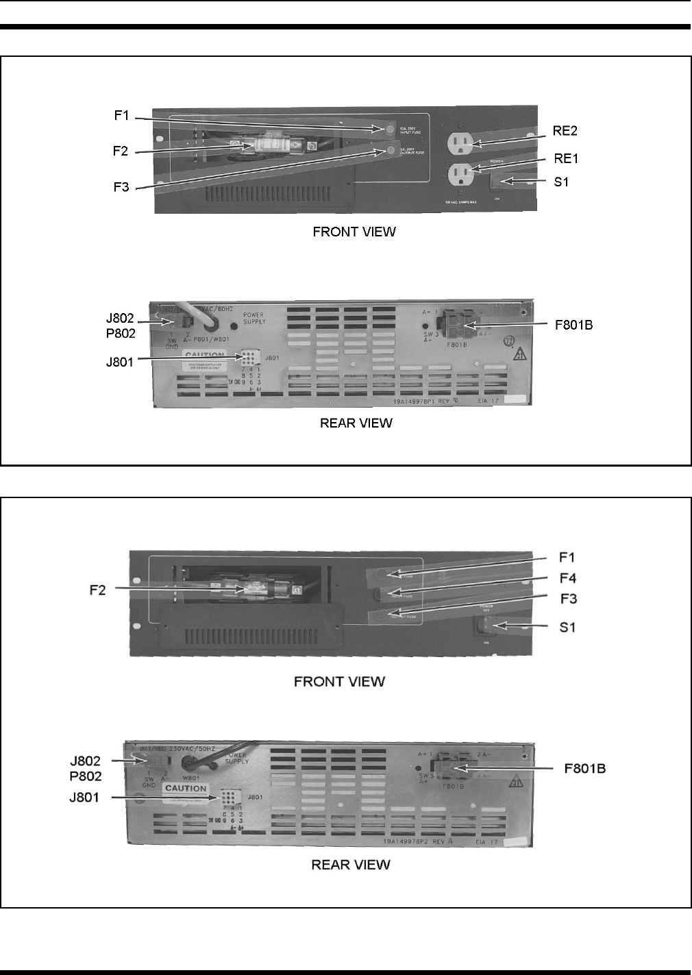
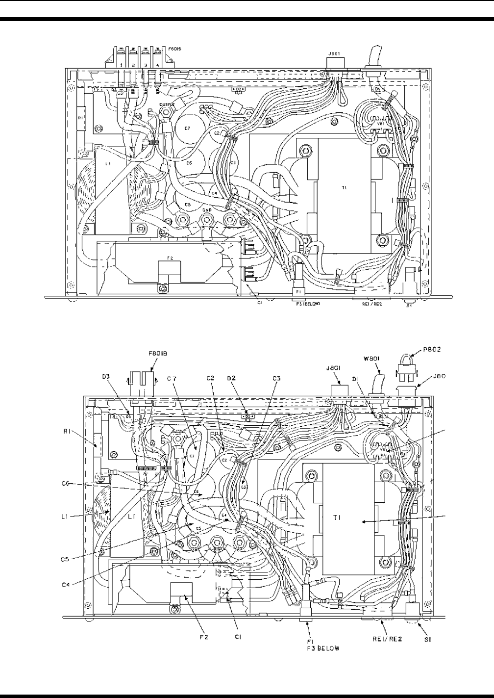
Figure 4 - 50 Hz Power Supply (19A149978P2, Rev. A)
Figure 3 - 60 Hz Power Supply (19A149978P1, Rev. B)
LBI-38550D
8
FUSE REPLACEMENT
To replace a defective fuse, perform the following pro-
cedure
1. Place ON/OFF switch to the OFF position.
2. For fuses F1 (F1 & F4 on 978P2) or F3, remove cap
from fuse holder and replace fuse with a fuse of the
same type and rating.
3. For fuse F2, remove two screws holding fuse cover
to front panel. Remove defective fuse and replace
with a fuse having the same type and rating. Replace
fuse cover and secure using the 2 screws.
Table 1 - 60 Hz Power Supply 19A149978P1
SYMPTOM PROCEDURE
No output voltage at J801 Check the following:
1. Open F1, F3 or S1
2. AC voltage on W801
3. Open D1, D2 or D3
No output voltage at F801B Check the following:
1. Open F1, F2 or S1
2. AC voltage on W801
3. Open D1, D2 or D3
Low output voltage on F801B or J801. Check the following:
0 < Vo < 12.5 Vdc 1. If one of the dual diodes on D1, D2 or D3 is shorted
NOTE: All three diode packages contain two diodes each
2. Line frequency < 60 Hz
High output voltage on F801B or J801. Check the following:
1. Spade jumper is connected between pos 2 and 3 on
F801B (Rev. A and earlier)
Vo . > 16.7 Vdc Plug P802 is connected to connector J802 (Rev. B and
later)
2. R1 not connected between pos 1 and 3 on F801B
No one should be permitted to handle any portion of
the equipment that is supplied with high voltage, or to
connect any external apparatus to the units while the
units are supplied with power. KEEP AWAY FROM
LIVE CIRCUITS.
To avoid electrical
WARNING
To avoid possible electric shock, DO NOT operate
this power supply with the fuse cover removed.
To avoid electrical
WARNING
LBI-38550D
9

TROUBLESHOOTING PROCEDURE
Table 2 - 50 Hz Power Supply 19A149978P2
SYMPTOM PROCEDURE
No output voltage at J801 Check the following:
1. Open F1, F3, F4 or S1
2. AC voltage on W801
3. Open D1, D3 or D3
No output voltage at F801B Check the following:
1. Open F1, F2, F4 or S1
2. AC voltage on W801
3. Open D1, D2 or D3
Low output voltage on F801B or J801. Check the following:
0 < Vo < 12.5 Vdc 1. If one of the dual diodes on D1, D2 or D3 is shorted
NOTE: All three diode packages contain two diodes each
2. Line frequency < 50 Hz
High output voltage on F801B or J801. Check the following:
1. Plug P802 is connected to connector J802
Vo . > 16.7 Vdc 2. R1 not connected between pos 1 and 3 on F801B
3. Line frequency > 50 Hz
LBI-38550D
10
TROUBLESHOOTING PROCEDURE
(33014904, Rev. F)
(33014900, Sh. 2, Rev. F)
(33014904, Rev. F)
(33014900, Sh. 1, Rev. F)
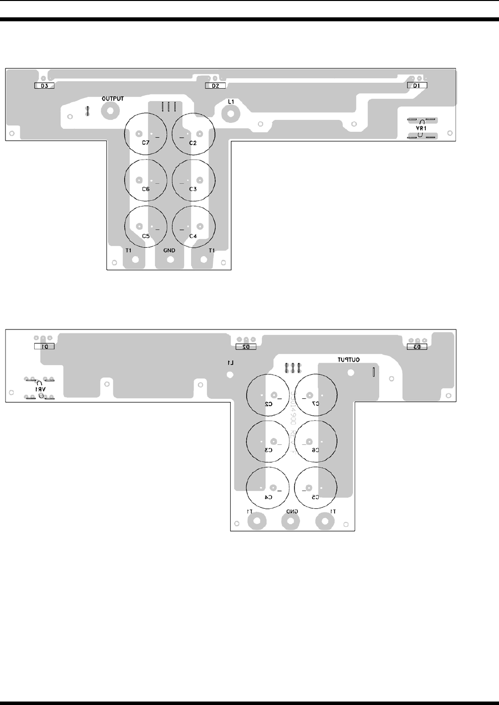
SOLDER SIDE
PRINTED CIRCUIT BOARD
50 HZ AND 60 HZ MODELS
COMPONENT SIDE
LBI-38550D
11
Rev. B
(Made from 289PS11, Sh. 2, Rev. A)
ASSEMBLY DIAGRAM
60 HZ POWER SUPPLY
19A149978P1
Rev. 0 & Rev. A
(Made from 289PS1, Rev. A)
LBI-38550D
12
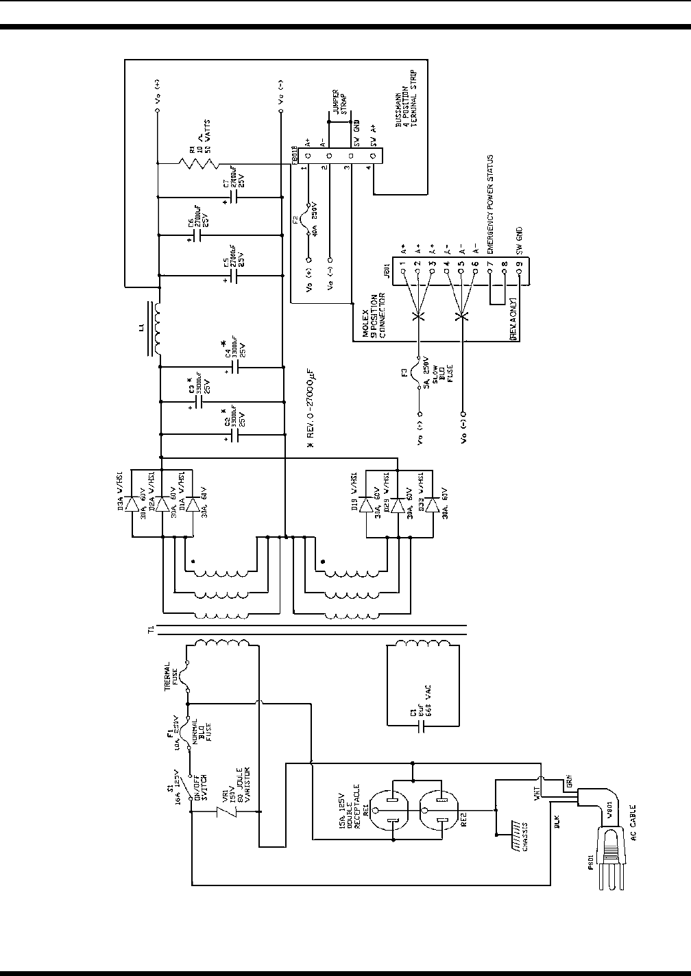
SCHEMATIC DIAGRAM
60 HZ POWER SUPPLY
19A149978P1, Rev. 0 & Rev. A
LBI-38550D
13
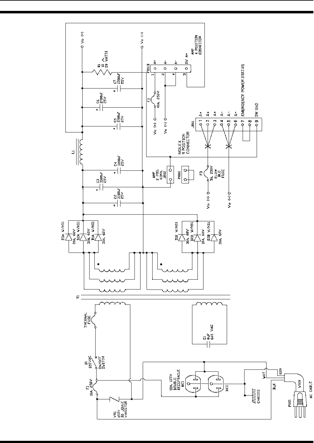
SCHEMATIC DIAGRAM
60 HZ POWER SUPPLY
19A149978P1, Rev. 0 & Rev. A
LBI-38550D
14
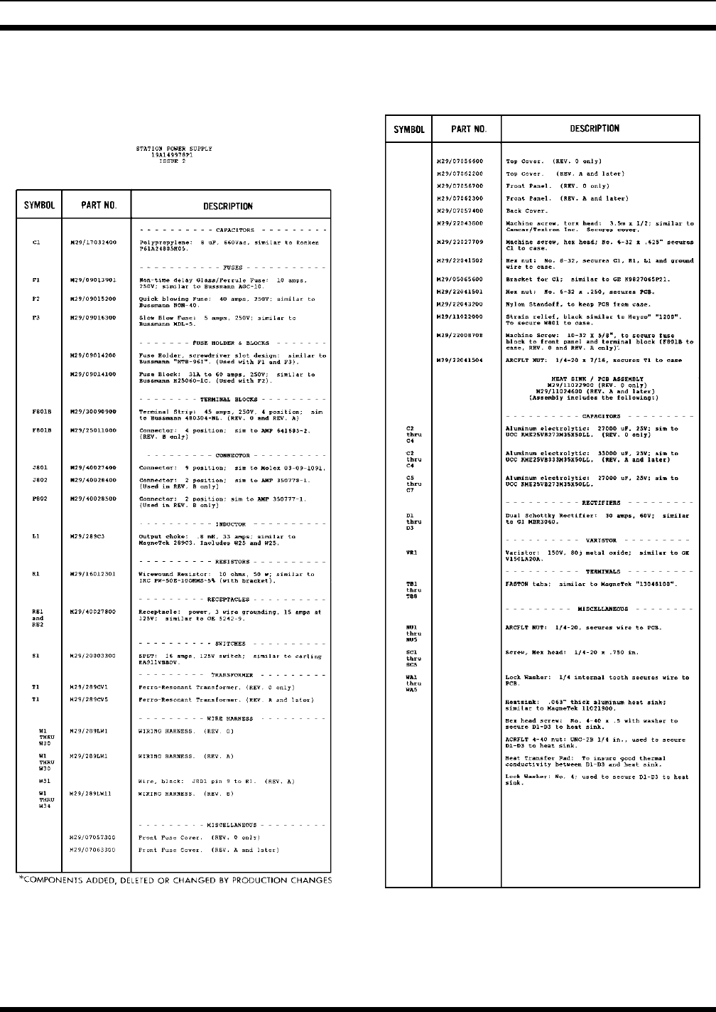
PARTS LIST LBI-38550D
15
(Made from 289PS2, Sh. 2, Rev.Q)
ASSEMBLY DIAGRAM
50 HZ POWER SUPPLY
19A149978P2
LBI-38550D
16
(289PS2, Sh. 1, Rev. H)
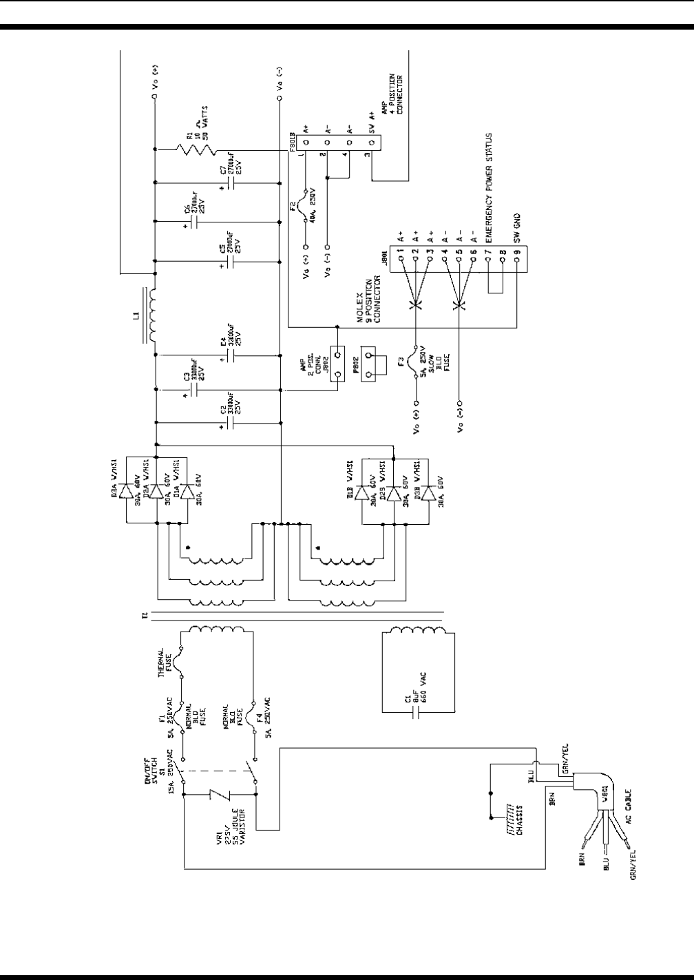
SCHEMATIC DIAGRAM
50 HZ POWER SUPPLY
19A149978P2
LBI-38550D
17
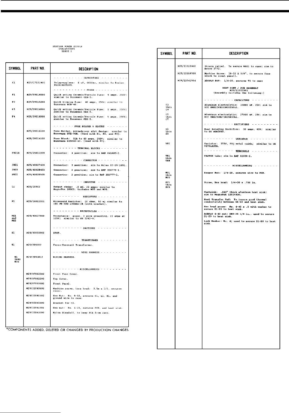
PARTS LIST
M/A-COM Wireless Systems
3315 Old Forest Road
Lynchburg, Virginia 24501
(Outside USA, 434-385-2400) Toll Free 800-528-7711
www.macom-wireless.com Printed in U.S.A.
LBI-38550D