HARRIS TR-0017-E Sitepro Base Station User Manual RF Package
HARRIS CORPORATION Sitepro Base Station RF Package
HARRIS >
Contents
RF Package

Maintenance Manual
LBI-38754F
M/A-COM Wireless Systems
3315 Old Forest Road
Lynchburg, Virginia 24501
(Outside USA, 434-385-2400) Toll Free 800-528-7711
www.macom-wireless.com Printed in U.S.A.
MASTR® III
RF Package, VHF
TABLE OF CONTENTS
TRANSMIT SYNTHESIZER . . . . . . . . . . LBI-38640
RECEIVE SYNTHESIZER . . . . . . . . . . . LBI-38641
RECEIVE RF MODULE . . . . . . . . . . . . . LBI-38642
IF MODULE . . . . . . . . . . . . . . . . . . . LBI-38643
LBI-39123
POWER AMPLIFIER . . . . . . . . . . . . . . LBI-38531
AE/LZB 119 3521/20
DUPLEXER . . . . . . . . . . . . . . . . . . . LBI-38763
Preliminary

Copyright© 1992 - 2002 M/A-COM Private Radio Systems, Inc. All rights reserved.
SAFETY NOTES
•The means of disconnecting power from a station cabinet is the cabinet power supply plug.
•When conducting repair/maintenance, disconnect the cabinet power supply plug from the AC source.
•In European applications, equipment must be installed in a closed cabinet.
•Only replace components with components specified by M/A-COM Private Radio Systems.
TABLE OF CONTENTS
Page
SPECIFICATIONS . . . . . . . . . . . . . . . . . . . . . . . . . . . . . . . . . . . . . . . . . . . . . . . . . . . . . 1
REGULATORY APPROVALS . . . . . . . . . . . . . . . . . . . . . . . . . . . . . . . . . . . . . . . . . . . . . . . 2
MODULE NUMBERS . . . . . . . . . . . . . . . . . . . . . . . . . . . . . . . . . . . . . . . . . . . . . . . . . . . 2
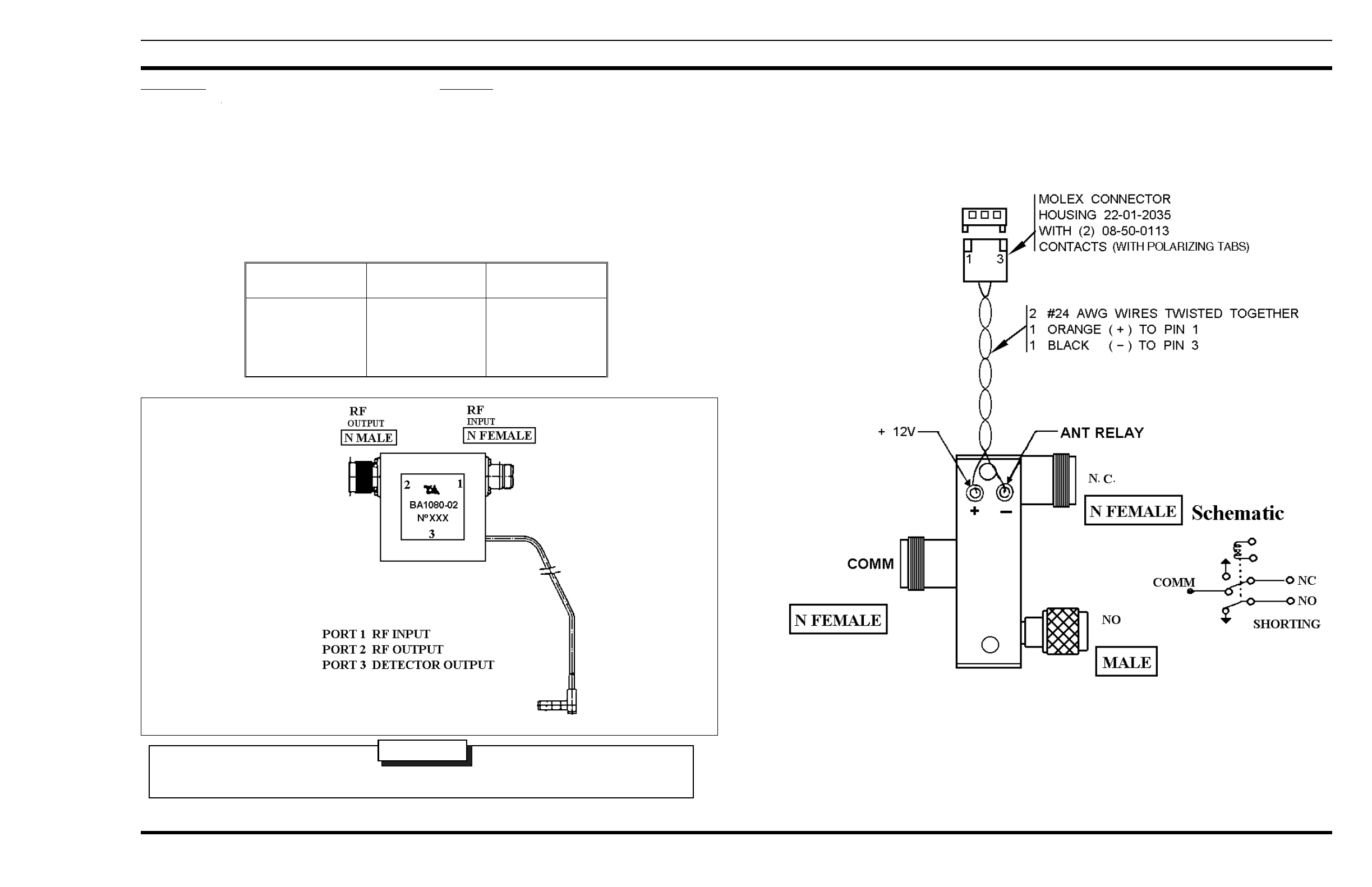
ISOLATOR . . . . . . . . . . . . . . . . . . . . . . . . . . . . . . . . . . . . . . . . . . . . . . . . . . . . . . . . . 3
ANTENNA SWITCH . . . . . . . . . . . . . . . . . . . . . . . . . . . . . . . . . . . . . . . . . . . . . . . . . . . . 3
INTERCONNECTION DIAGRAM . . . . . . . . . . . . . . . . . . . . . . . . . . . . . . . . . . . . . . . . . . . . 4
Table 1 - Station Specifications
ITEM SPECIFICATION
RECEIVER
SENSITIVITY (12 dB SINAD)
SELECTIVITY (25 kHz)
(30 kHz)
INTERMODULATION REJECTION
INTERMEDIATE FREQUENCY
IMAGE REJECTION
SPURIOUS RESPONSE REJECTION
HUM & NOISE (300-3000 Hz)
AUDIO RESPONSE (de-emphasis)
FREQUENCY SPREAD (range)
(full specification)
(3 dB degradation)
TRANSMITTER
RATED POWER OUTPUT
FREQUENCY STABILITY
CONDUCTED SPURIOUS EMISSIONS
MODULATION DEVIATION
FM HUM & NOISE (300-3000 Hz)
AUDIO RESPONSE (pre-emphasis)
FREQUENCY SPREAD (range)
(full specification)
-116 dBm (0.35 µV)
-95 dB
-100 dB
-90 dB
21.4 MHz (low-side injection)
-100 dB
-100 dB
-55 dB
+1/-3 dB of 6 dB/Octave (@ Line Output)
+2/-8 dB of 6 dB/Octave (@ Local Speaker)
136.0-151 MHz, 150.8-174 MHz
2 MHz
3 MHz
110 Watts
±1.5 ppm
-36 dBm
±5 kHz
-55 dB
+1/-3 dB of 6 dB/Octave
136.0-151 MHz, 150.8-174 MHz
136.0-151 MHz, 150.8-174 MHz
SPECIFICATIONS
Repairs to this equipment should be made only by an authorized service technician or facility designated by the supplier. Any
repairs, alterations or substitution of recommended parts made by the user to this equipment not approved by the manufacturer
could void the user’s authority to operate the equipment in addition to the manufacturer’s warranty.
NOTICE!
This manual is published by M/A-COM Private Radio Systems, Inc., without any warranty. Improvements and changes
to this manual necessitated by typographical errors, inaccuracies of current information, or improvements to programs
and/or equipment, may be made by M/A-COM Private Radio Systems, Inc., at any time and without notice. Such changes
will be incorporated into new editions of this manual. No part of this manual may be reproduced or transmitted in any
form or by any means, electronic or mechanical, including photocopying and recording, for any purpose, without the
express written permission of M/A-COM Private Radio Systems, Inc.
The software contained in this device is copyrighted by the M/A-COM Private Radio Systems, Inc. Unpublished rights are
reserved under the copyright laws of the United States.
NOTICE!
LBI-38754G
1

REGULATORY APPROVALS
The following equipment authorization numbers have been granted:
COUNTRY REGULATORY APPROVAL
United States FCC (Parts 15, 22, 74, 80, 90) AXATR-197-A2
Canada DOC (RSS-119) TR-197
MODULE NUMBERS
TRANSMIT SYNTHESIZER . . . . . . . . . . . . . . . . . . . . . . . . . . 19D902780G1
RECEIVE SYNTHESIZER (150.8-174 MHz) . . . . . . . . . . . . . . . . 19D902781G1
(136.0-151 MHz) . . . . . . . . . . . . . . . . 19D902781G2
RX FRONT END MODULE (150.8-174 MHz) . . . . . . . . . . . . . . . . 19D902782G2
(136.0-151 MHz) . . . . . . . . . . . . . . . . 19D902782G1
IF MODULE . . . . . . . . . . . . . . . . . . . . . . . . . . . . . . . . . . . 19D902783G1
POWER AMPLIFIER . . . . . . . . . . . . . . . . . . . . . . . . . . . . . . 19D902797G1
. . . . . . . . . . . . . . . . . . . . . . . . . . . . . . . . . . . . . . . . . . 19D902797G20
. . . . . . . . . . . . . . . . . . . . . . . . . . . . . . . . . . . . . . . . . . 19D902797G21
LOW PASS FILTER . . . . . . . . . . . . . . . . . . . . . . . . . . . . . . . 19D902856G1
ANTENNA SWITCH . . . . . . . . . . . . . . . . . . . . . . . . . . . . . . 19B235897P1
ISOLATOR . . . . . . . . . . . . . . . . . . . . . . . . . . . . . . . . . . . . 344A3406P2
DUPLEXER (150-162 MHz) . . . . . . . . . . . . . . . . . . . . . . . . . . 344A3371P1
DUPLEXER (162-174 MHz) . . . . . . . . . . . . . . . . . . . . . . . . . . 344A3371P2
LBI-38754G
2

ACCESSORIES
REFLECTED POWER VSWR TYPICAL
SENSOR VOLTAGE
10W
15W
20W
25W
30W
1.70:1
1.92:1
2.15:1
2.38:1
2.62:1
3.9V
4.8V
5.7V
6.4V
6.8V
Specifications
Frequency Range 136-174 MHz (no tuning)
Input Power 150 W (at max VSWR of 3.7:1)
Short Circuit Duration 100 ms max
Insertion Loss 0.3 dB max (25°C)
0.8 dB max (-40°C to +85°C)
Isolation 18 dB min (25°C)
15 dB min (-40°C to +85°C)
Description
The isolator has an internal load connected to an RF
detector (sensor), the output from the sensor is continually
monitored by the sttion for a fault conditon (high VSWR).
Once the station detects a sensor voltage above the threshold
the transmitter is automatically de-keyed and a FAULT con-
dition is reported.
IMPORTANT:
ANTENNA SWITCH
19B235897P2
DO NOT USE ISOLATOR WITHOUT CONNECTING THE SENSOR TO THE STATION
WARNING
ISOLATOR
344A3406P1
The sensor output must be connected to
P108 on the Interface Board when the Iso-
lator is used, failure to make this connection
with the Isolator installed will cause the
isolator to be damaged under high VSWR
conditions.
LBI-38754G
3

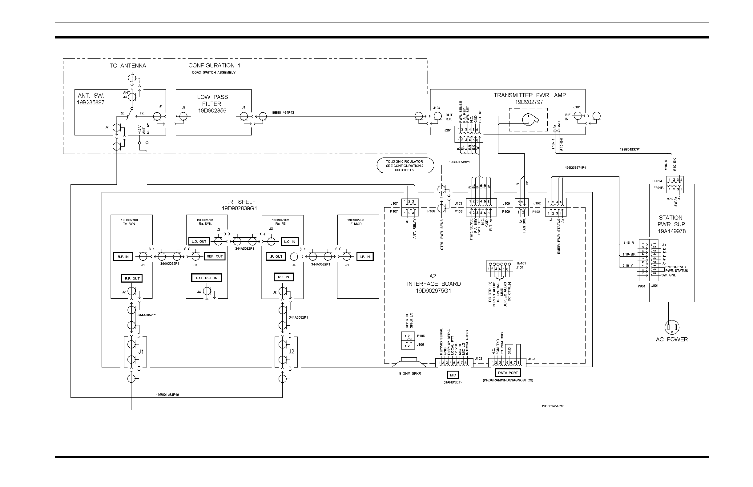
INTERCONNECTION DIAGRAM
MASTR III STATION
(19D903635 Sh. 1, Rev. 4)
LBI-38754G
4

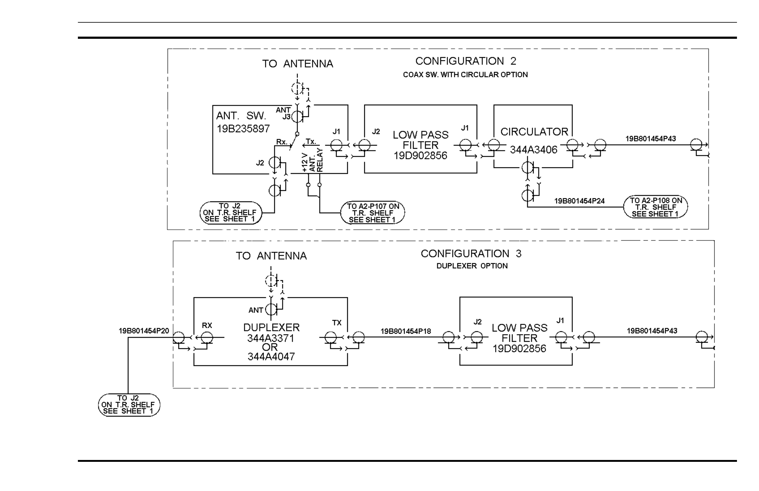
INTERCONNECTION DIAGRAM
MASTR III STATION
(19D903635, Sh. 2, Rev. 6)
LBI-38754G
5