INTO TECH REALDISPLAY DVR BD User Manual Part 2
Intotech Inc. DVR BD Users Manual Part 2
Contents
- 1. Users Manual Part 1
- 2. Users Manual Part 2
Users Manual Part 2
GGGGGGGGGGGGGGGGGGGGGGGGGGGGGGGSmartDVR Formula 2.0G
-31-G
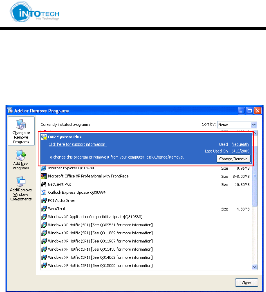
2-2-3. Uninstall DVR Server program
1. Under the Start menu in Windows, go to Setting and then to Control Panel
2. Double click the Add or Remove Programs
3. Select DVR System Plus and Click on Change/Remove button.
3. Click Remove button and Press the [Next] button.
4. Press the Finish button to complete uninstalling DVR program.
The uninstall program will delete all DVR system files on your hard disk. However, it does not
delete the video images and the log files already saved in the hard drive of your DVR PC.
GGGGGGGGGGGGGGGGGGGGGGGGGGGGGGGSmartDVR Formula 2.0G
-32-G
Chapter 3 User Manual for SmartDVR Formula v2.0
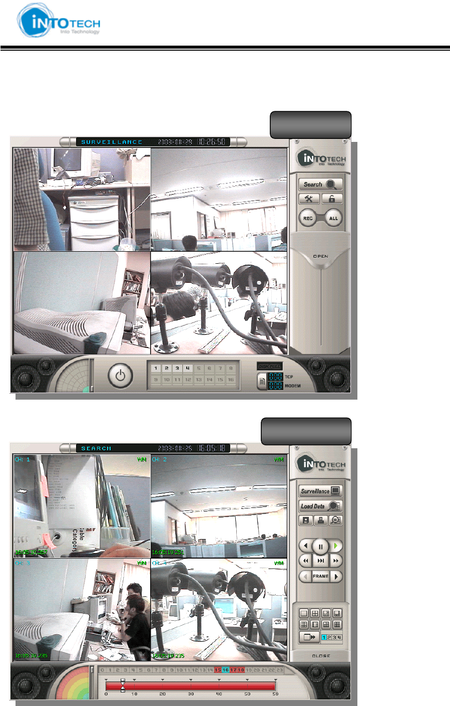
Monitoring Screen (Main View) Mode
Search Screen Mode
View Screen
Search Screen

GGGGGGGGGGGGGGGGGGGGGGGGGGGGGGGSmartDVR Formula 2.0G
-33-G
3-2. General User Guide
3-1 Main features and functions
1. Operating System (O/S)
DVR system uses Windows 2000/XP as a basic OS and is designed to operate all needed
functions of DVR System properly.
2. Main Program
The main program operates Search, Backup, Recording, and every function to control DVR
System and it has the following functions and features
1) Easy to search
According to date, time, and camera, the user is able to execute instant, speedy, conditional,
and magnified searched video images.
2) Backup & Print function
Able to print out searched images and provides Backup function
3) Switcher (Auto –Selector) function
4) Screen Division Function
The user is able to select the following screen division: 1, 4, 8, 9, 10, 13, 16, and full screen
5) Record speed control function
The user is able to adjust recording rate
6) Record qualify setup per CH function
Able to manage HDD space efficiently by adjust recording quality per channel
7) Motion Detection Function (MD)
The user is able to setup motion area, and record the image when the motion image is
detected in the area.
(Recording, Event processing function)
8) PAN/TILT Control Function
P/T/Z built in the system (Requirement of Receiver Device)

GGGGGGGGGGGGGGGGGGGGGGGGGGGGGGGSmartDVR Formula 2.0G
-34-G
9) Alarm connection with Camera & Sensor
Connect with emergency bell and alarm while MD & Sensor are operating
10) Watch Dog
When system function does not operate properly or emergency shutdown, watchdog function
operates auto reset/restoration existed data
11) Water Mark
A copyright-protection method of embedding a code into a digital audio or video file to
attempt to thwart piracy or unlicensed use
12) Image Transmission (Option)
Remote sites image transmission by using PSTN
(Able to monitor remote sites from Web Browser and NetClient program)
13) Store Resolutions
Support 320×240 pixels, 640x480 pixels
14) Line Monitoring - Image Signal Monitoring Function
15) Schedule
16) Record, Digital-Out, and Alarm function
17) Password
GGGGGGGGGGGGGGGGGGGGGGGGGGGGGGGSmartDVR Formula 2.0G
-35-G
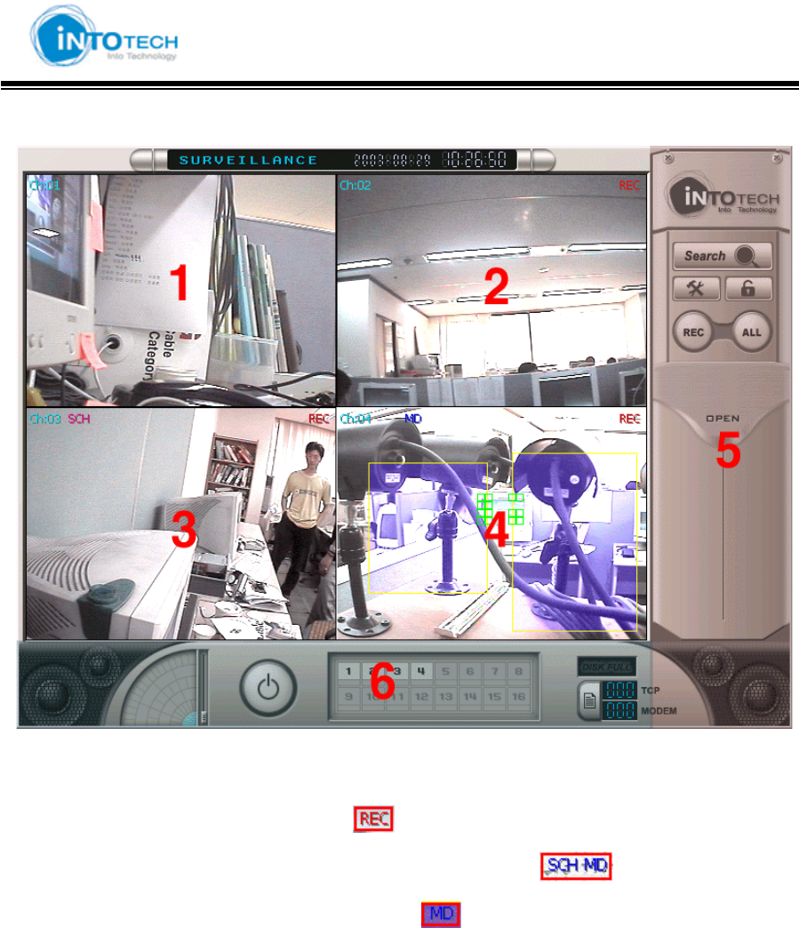
3-2 Monitoring Screen Mode
1 : Standard Display Screen
2 : 1CH recording screen (represented by )
3 : Schedule Motion Detection Recording Screen (represented by )
4 : Motion Detection Store Screen (represented by )
5, 6 : Please refer to full description as below
- Next Page -
GGGGGGGGGGGGGGGGGGGGGGGGGGGGGGGSmartDVR Formula 2.0G
-36-G
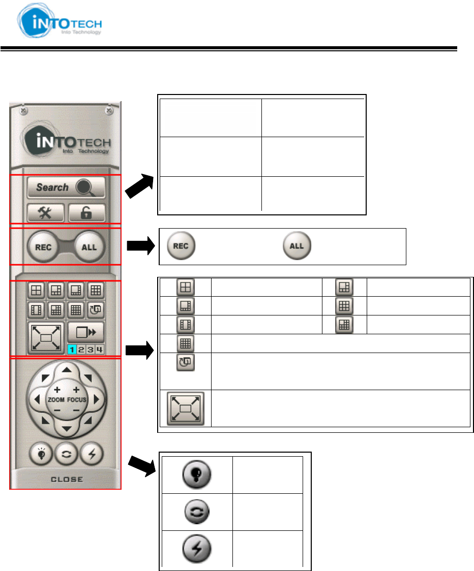
5 Full Description (Part A)
Search Mode
Configuration
Lock /Unlock
G4 CH Mode 6 CH Mode
G8 CH Mode 9 CH Mode
G10 CH Mode 13 CH Mode
G16 CH Mode
G<Switching Mode> = Automatically switch to next
screen through periodic time
Full Display Mode
G
Light
On/Off
GAuto Pan
G
P/T/Z
Power
GaGyGGGGGGGG G aGhG G
GGGGGGGGGGGGGGGGGGGGGGGGGGGGGGGSmartDVR Formula 2.0G
-37-G
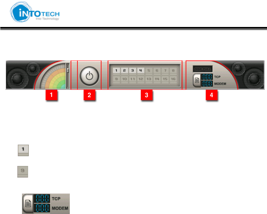
6 : Full Description (Part B)
1 : Sound volume control
2 : Power
3 : : Camera On
: Camera Off
4 : Indicate item under LAN / MODEM connection
TCP : support up to max. 100 users
MODEM: support one user
GGGGGGGGGGGGGGGGGGGGGGGGGGGGGGGSmartDVR Formula 2.0G
-38-G
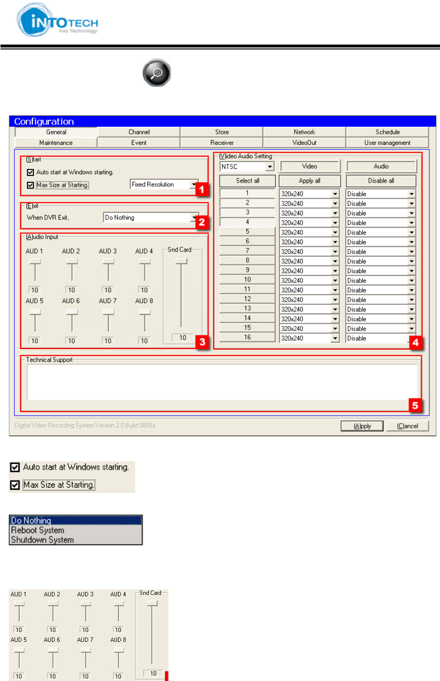
Double Click on configuration ( ) icon in Main View Screen.
1) General
1. Start Windows
: Automatically execute program when start of Windows
: Execute Full Screen Size when run DVR program
2. Exit DVR program
: Only exit DVR Program
: Restart Windows when exit DVR program
: Shutdown Windows when exit DVR program
3. Audio volume control
: Audio volume setting
: Setup volume for AUD 1 ~ AUD8
: Snd Card = Setup Sound Card volume.
GGGGGGGGGGGGGGGGGGGGGGGGGGGGGGGSmartDVR Formula 2.0G
-39-G
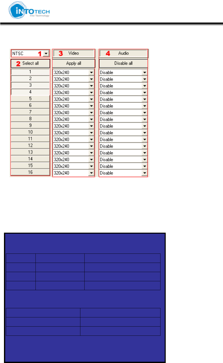
4. Camera and audio configuration
1 : Select camera type (NTSC, PAL)
2 : Select camera channel
3 : Select display resolution for each camera channel
4 : Select audio device
5 : Indicate technical support information
<TIP>
1. Video Resolution
320x240 640x480
SDVR 16CH 16CH
HDVR 16CH 16CH
HPLUS 16CH Support up to 6CH
2. Audio
SDVR Support up to 2CH
HDVR Support up to 5CH
HPLUS Support up to 9CH
G
GGGGGGGGGGGGGGGGGGGGGGGGGGGGGGGSmartDVR Formula 2.0G
-40-G
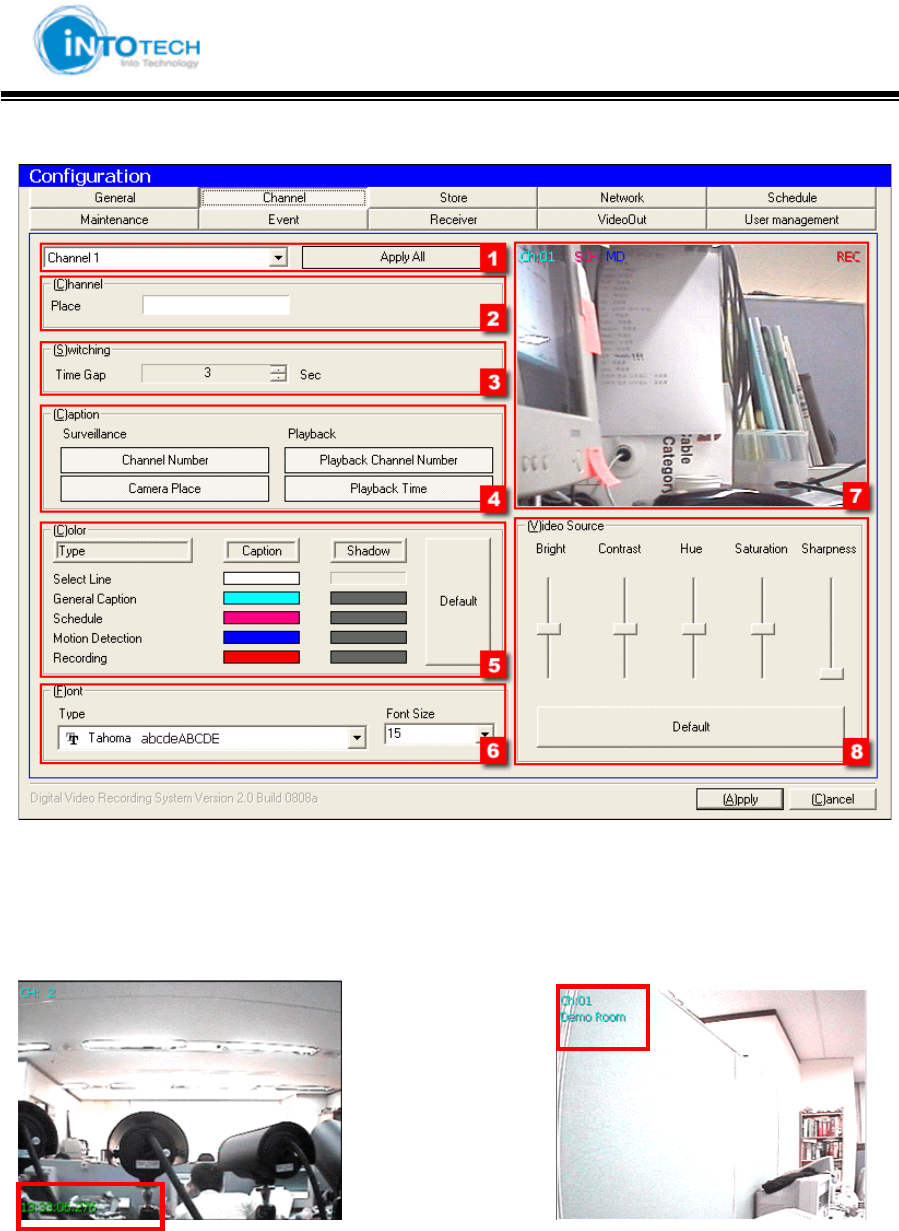
2) Channel
1. Selecting the camera CH/Apply change to all camera CH
2. Insert the place name of selected camera
3. Switching delay time for screen-partition mode
4. (Search Screen) (Monitoring Screen)
GGGGGGGGGGGGGGGGGGGGGGGGGGGGGGGSmartDVR Formula 2.0G
-41-G
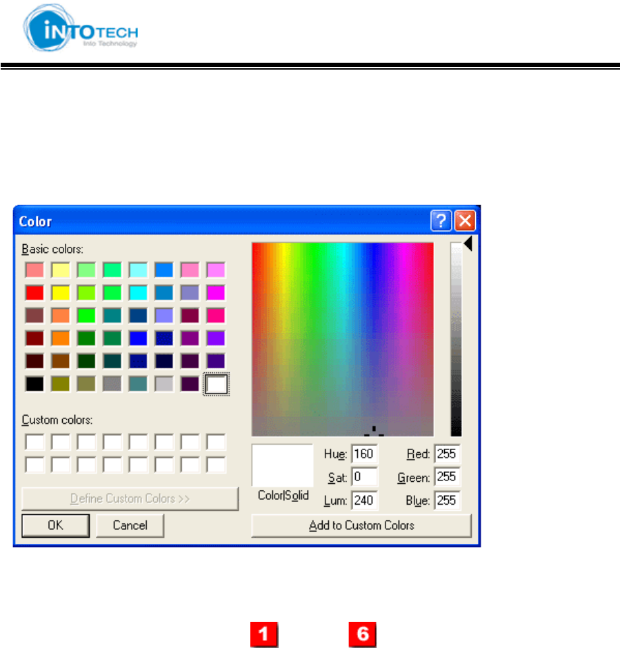
5 : Assign control color tone
(Direction)
Click color you wish to change
Select Color you wish to change and then click confirmation button
6 : Select you wish to change character form, and size
7 : Preview selected result from step ( ) ~ to step ( )
8 : Adjust Picture Quality
GGGGGGGGGGGGGGGGGGGGGGGGGGGGGGGSmartDVR Formula 2.0G
-42-G
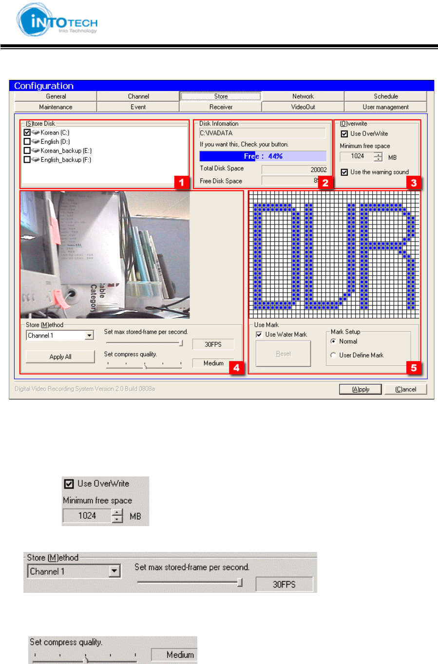
3) Store
1 : Check the HDD where you want to use for storage
2 : Indicates total HDD space for selected HDD in [1].
3 : Select to use overwrite function
EX> Start to overwrite when HDD Free space becomes 512 MB
4 : Display Picture Quality and Setting stored-frame
Display frame number of each channel (30Frame per Second)
: Higher FPS provides more natural image
Setting compress quality
GGGGGGGGGGGGGGGGGGGGGGGGGGGGGGGSmartDVR Formula 2.0G
-43-G
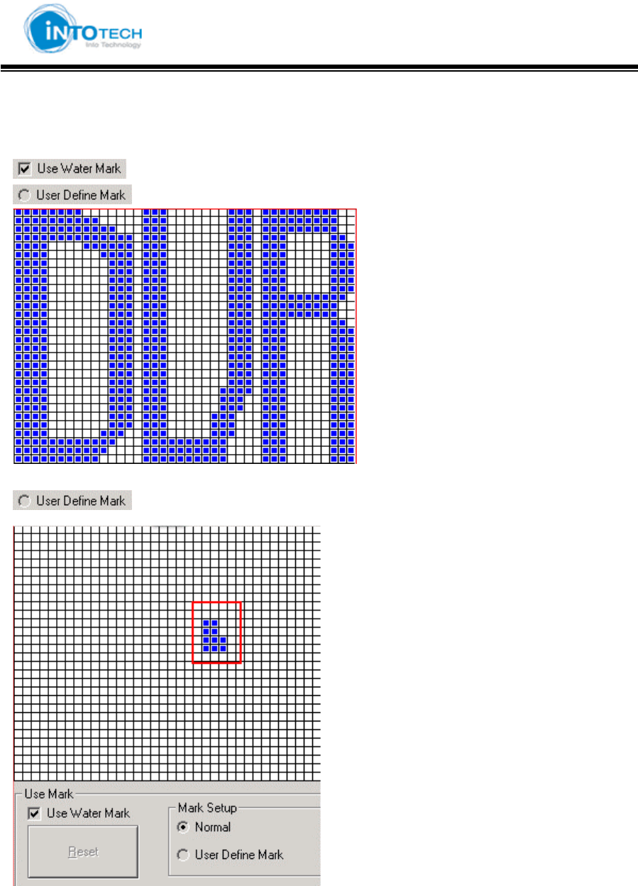
5 : Watermark Setup
: Select Watermark
: Display DVR Mark as default image
: The user can define own mark
GGGGGGGGGGGGGGGGGGGGGGGGGGGGGGGSmartDVR Formula 2.0G
-44-G
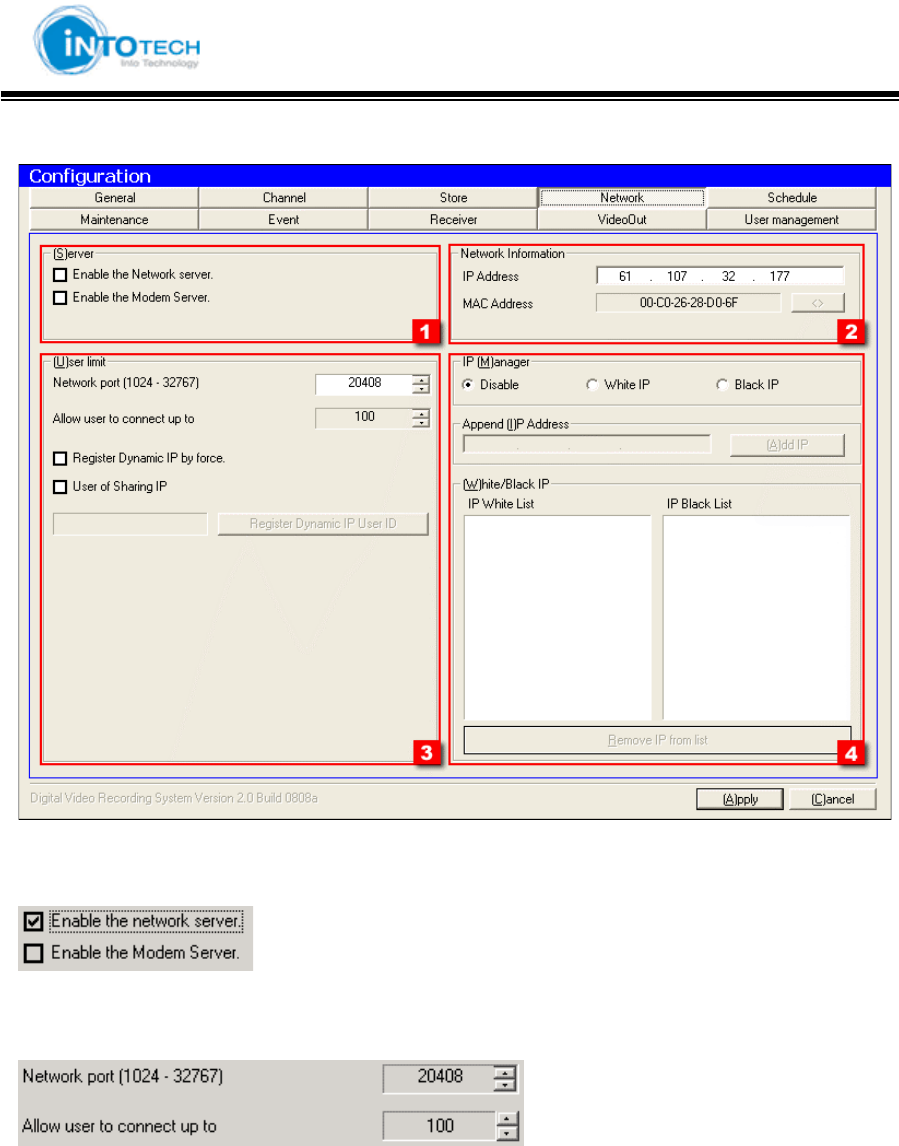
4) Network
1.: Network Server
: Use LAN
: Use MODEM
2 : Indicates DVR IP address and MAC address.
3.: Limit of possible simultaneous client connection
Network Access Port: Select Port No. while Client is accessing to Server
Max. Accessing User Number: Assign Accessing User Number (Max. 100 Client number)
GGGGGGGGGGGGGGGGGGGGGGGGGGGGGGGSmartDVR Formula 2.0G
-45-G
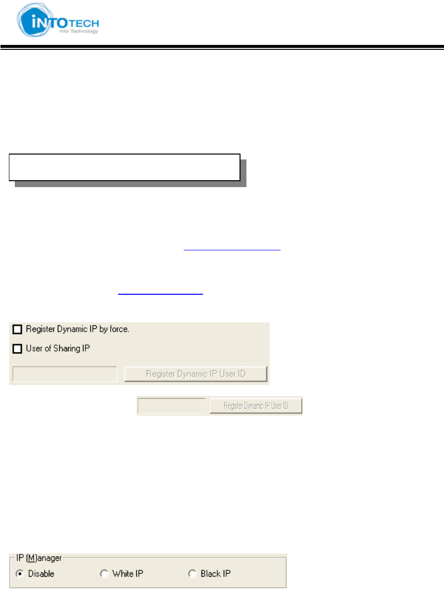
ୖ Register Dynamic IP
: Service for dynamic IP users
Dynamic IP users IP address changes frequently which causes inconvenience to check IP
address each time when connection. DHS executes a role as fixing Dynamic IP to Static IP.
For more information please connect to http://chainip.com/eng
For any questions regarding DHS service, please contact:
TEL: 82-2-566-3288 OR dhs@intotech.co.kr
For Dynamic IP users when ( ) part is not activated:
Please click ‘register Dynamic IP by force’
For Sharing IP users
: Please click ‘User of Sharing IP’
4. IP Manager setup
IP Manager configuration Disable : Allow any IP for connection.
White IP : Allow selected IP for connection.
Black IP : Prohibit connection of selected IP.
GDHS ( Dynamic Host Services)
GGGGGGGGGGGGGGGGGGGGGGGGGGGGGGGSmartDVR Formula 2.0G
-46-G
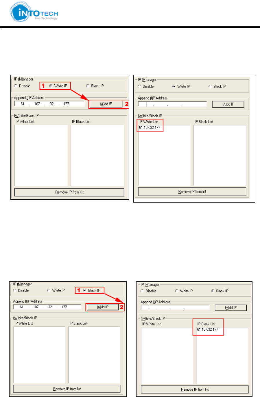
ୖ Network Configuration ୖ
(White IP setup)
< ㉘㥉 㤸 >
< Before setup > < After setup >
1 : Click White IP in [1].
2 : If ‘Add IP’ is activated please insert IP address.
3 : Cllick [2] button and IP address will be added to White IP List.
(Black IP setup)
< Before setup > < After setup >
1 : Click Black IP in [1].
2 : If ‘Add IP’ is activated please insert IP address.
3 : Click [2] button to add IP in Black IP List.
GGGGGGGGGGGGGGGGGGGGGGGGGGGGGGGSmartDVR Formula 2.0G
-47-G
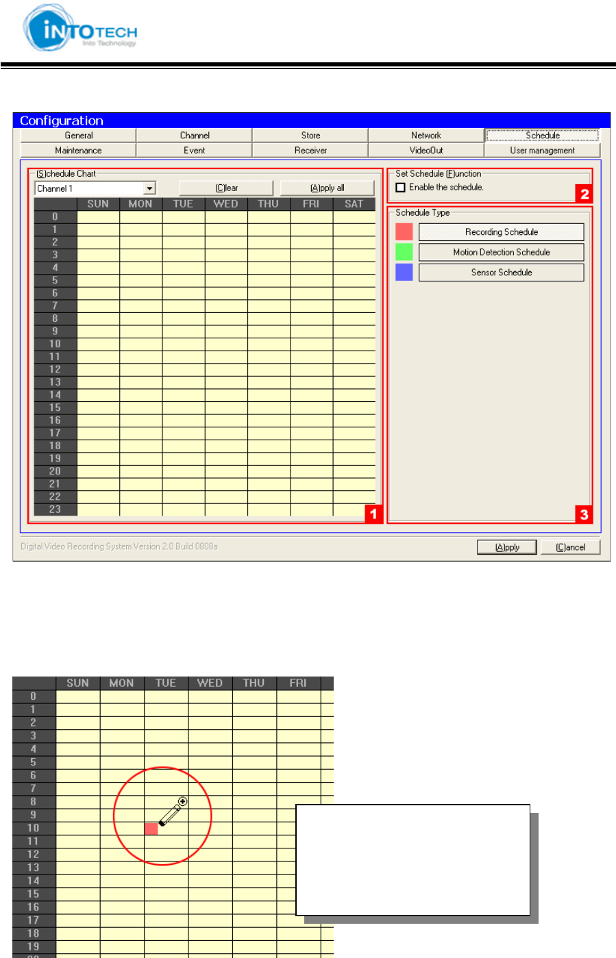
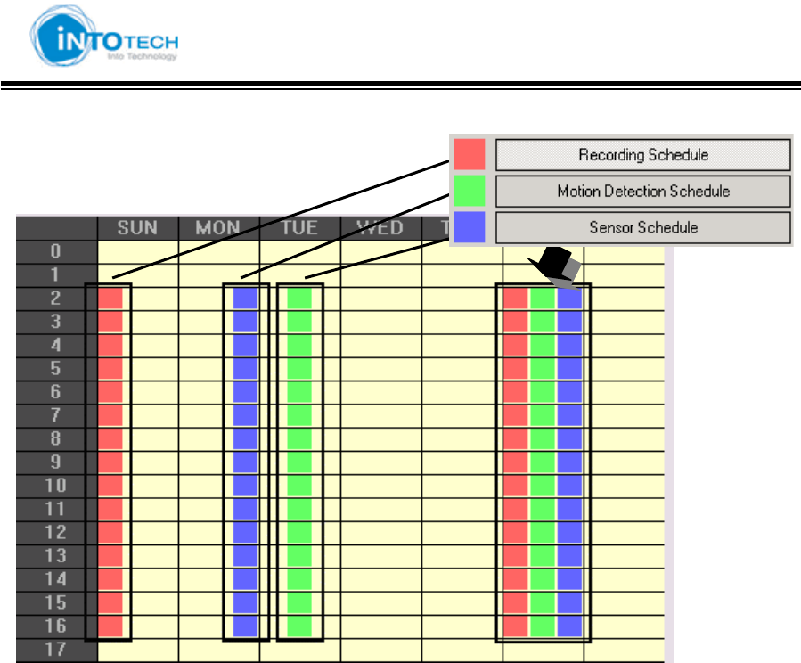
5) Schedule
1, 3 : Setup Recording, MD, Sensor schedule.
2 : Choose channel in [1].
[1, 3 Schedule setup]
Draw>
Click Mouse-Left button to Drag
Erase>
Click Mouse-Right button to Drag
GGGGGGGGGGGGGGGGGGGGGGGGGGGGGGGSmartDVR Formula 2.0G
-48-G
GGGGGGGGGGGGGGGGGGGGGGGGGGGGGGGSmartDVR Formula 2.0G
-49-G
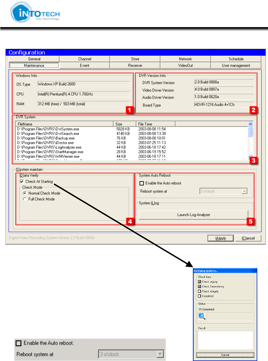
6) Maintenance
1 : Display Windows Information (OS, CPU, RAM)
2 : Display DVR Information
3 : Display operating program contents of DVR System
4 : Select Data Verification as run DVR program
Normal Check Mode: Ordinary Check (Fast Checking Speed)
Full Check Mode: Detail Check (Slow Checking Speed)
5 : Auto reboot system
.
GGGGGGGGGGGGGGGGGGGGGGGGGGGGGGGSmartDVR Formula 2.0G
-50-G
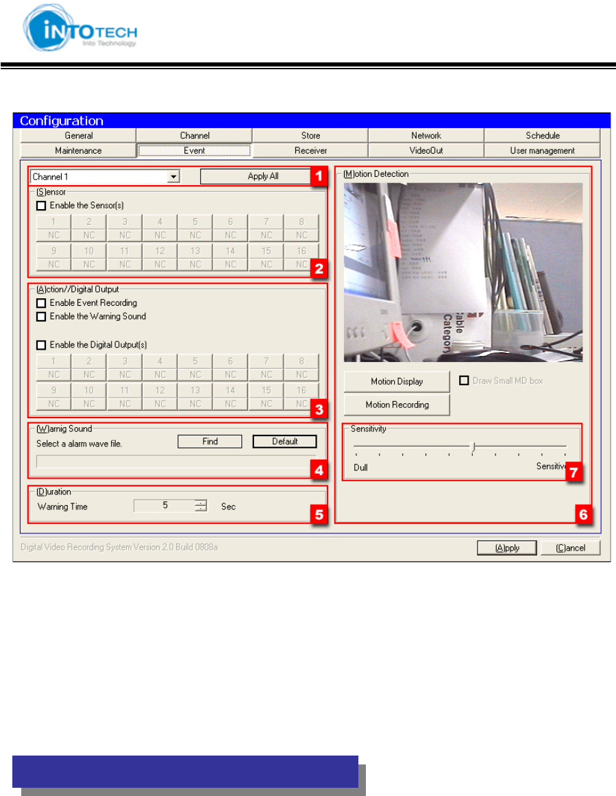
7) Event
1 : Select camera channel you wish to change
Click Apply All button to apply all channels
2 : Setting up Sensor of existing operating camera channel (Optional)
3 : Setting up Digital Output(Optional)
4 : Select any Warning Sound.
5 : Duration of warning time when sensor input.
(
Item 2, 3, 4
)
a
pp
lies onl
y
when I/O installed in DVR
GGGGGGGGGGGGGGGGGGGGGGGGGGGGGGGSmartDVR Formula 2.0G
-51-G
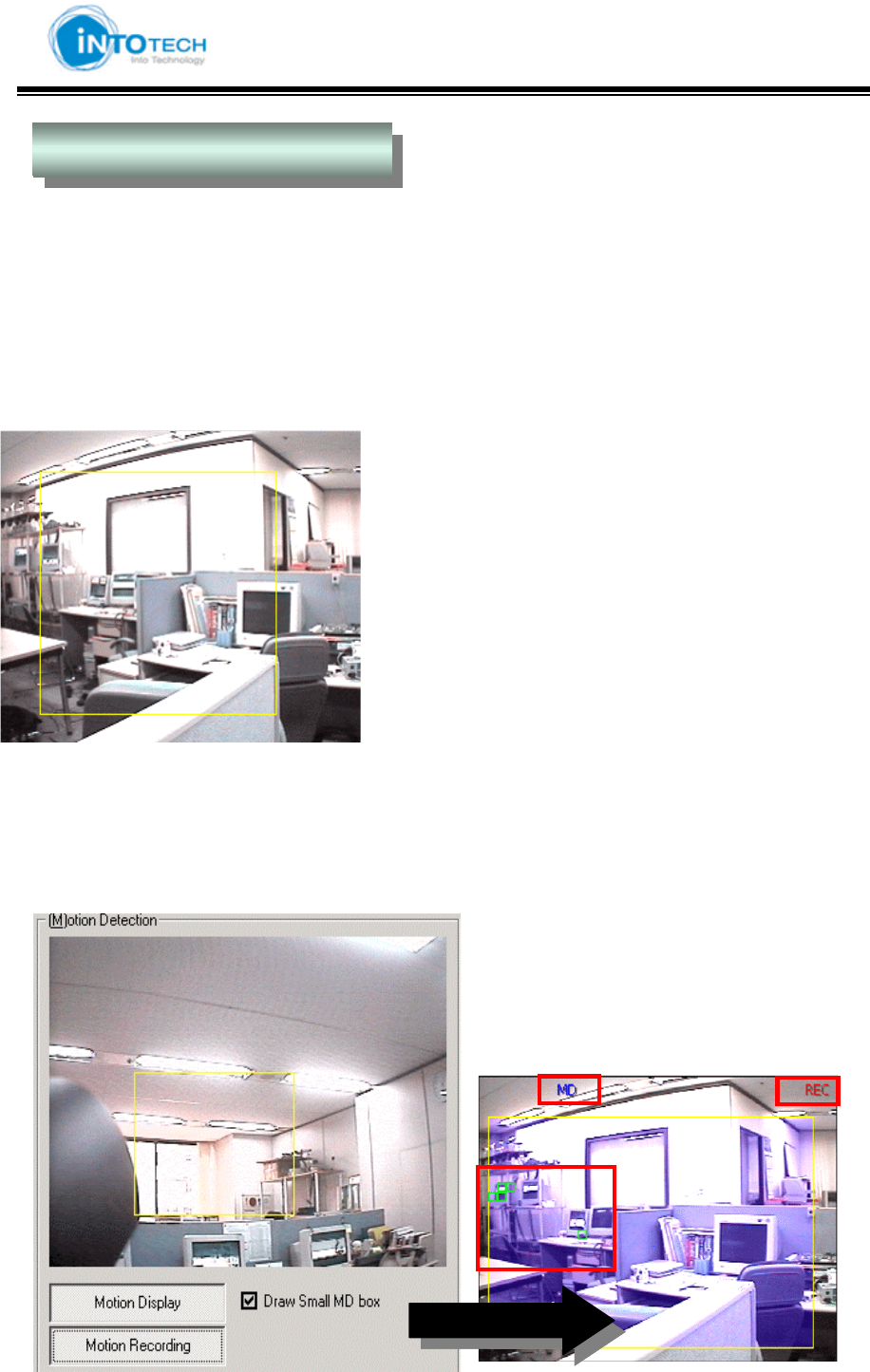
Motion Detection StoreG
Motion detection is to detect any relevant changes in the image or video.
Motion detection demonstrates how sensitive peripheral version is to motion.
At a certain point, you can no longer see the object. If the object starts moving, you will become
aware of it, even though you could not see it while it was stationary.
<Picture 1> MD Setting Area
Mouse-Left button Drag and Drop: Select MD Area
Mouse-Right button Drag and Drop: Unselect MD Area
Mouse Left button Double Click: Select all of the Area
Mouse Right button Double Click: Unselect all of the Area
<Picture 1>
6 : Motion Detection Configuration
- Check Point : Motion Detection Display, MD Driven-Recording, Draw Small MD Box
GGGGGGGGGGGGGGGGGGGGGGGGGGGGGGGSmartDVR Formula 2.0G
-52-G
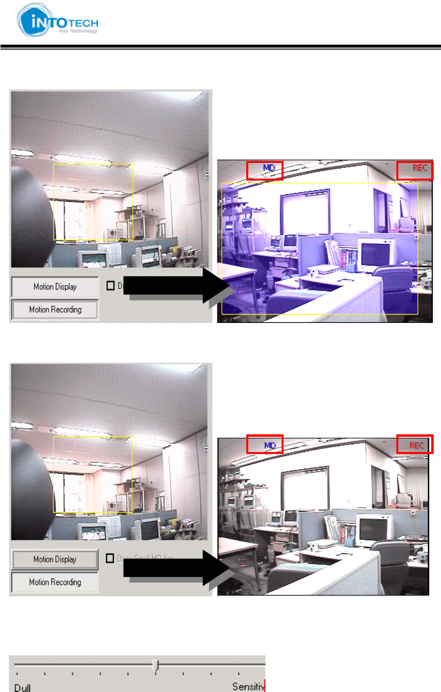
- Check Point : Display MD, Record MD images
- Check Point : Record MD images
7 : MD Sensitivity Setting
GGGGGGGGGGGGGGGGGGGGGGGGGGGGGGGSmartDVR Formula 2.0G
-53-G
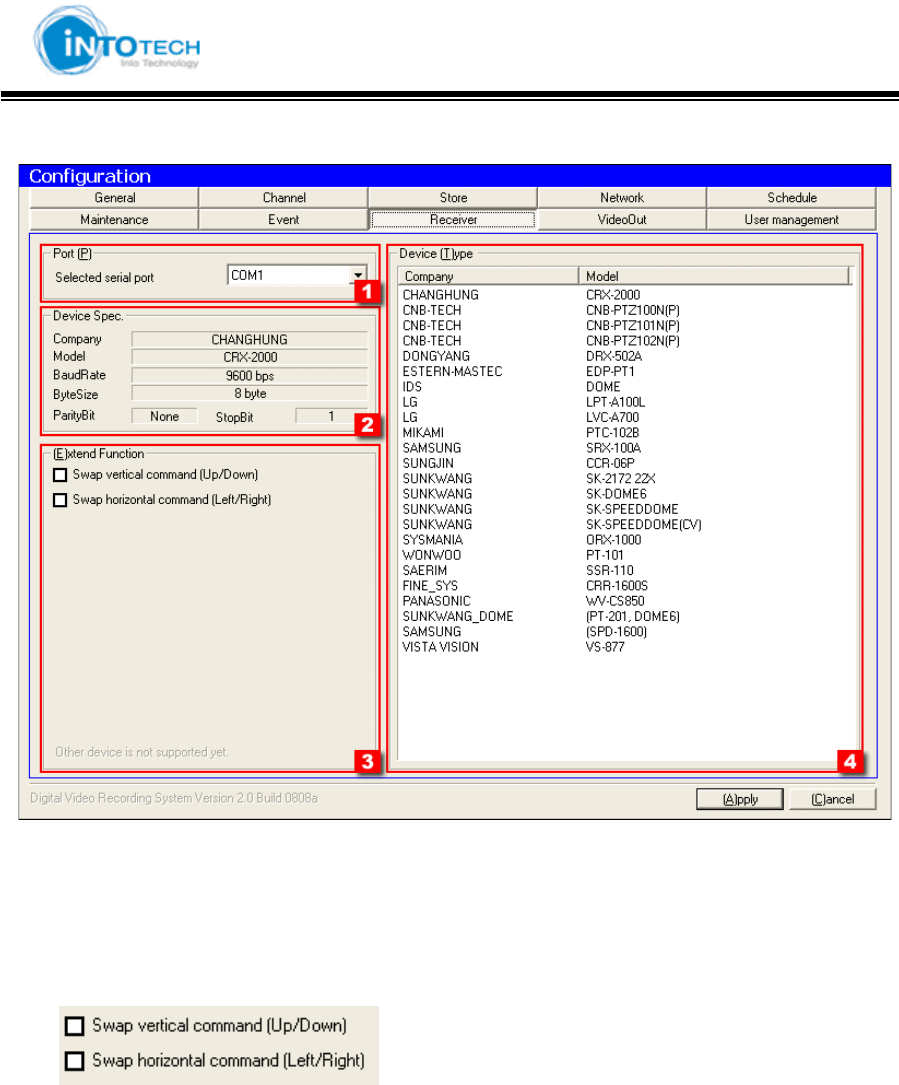
8) Receiver
1 : Select the serial port to use (COM1,COM2))
2 : Display current receiver information
3 : For expansion of Pan/Tilt function
: Swap vertical command of P/T protocol.
: Swap horizontal command of P/T protocol.
4 : Available receiver list: (Select the receiver to use)
Address of Receiver has to be equal to the channel number. Also you have to use same
device. (EX: Channel 1 => HW Address)
GGGGGGGGGGGGGGGGGGGGGGGGGGGGGGGSmartDVR Formula 2.0G
-54-G
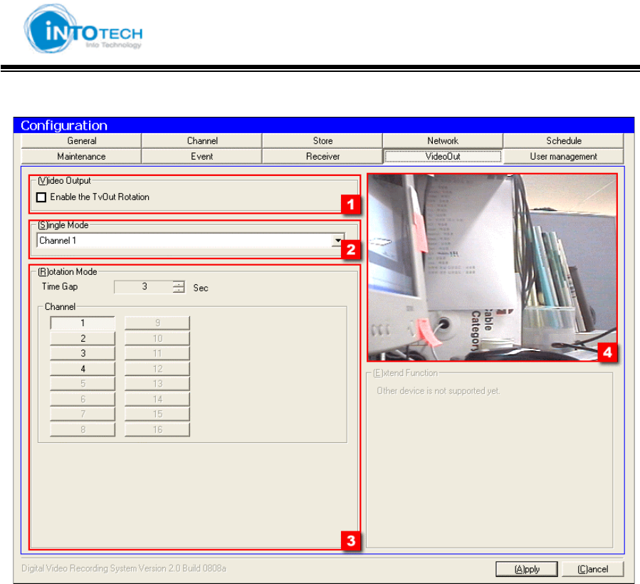
9) VideoOut
1 : Setting Output CH number through TV-Out (Option)
2 : Select TV-Out CH
3 : Setup time of Switching Mode
4 : Appear Preview Screen

GGGGGGGGGGGGGGGGGGGGGGGGGGGGGGGSmartDVR Formula 2.0G
-55-G
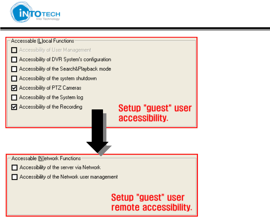
10) User Management
1 : User List
2 : Log In/Out management
: Automatic log out function after setup time
: Enable login & out function.
3 : Authorization of local functions and remote control
< Add users >
: Insert User ID and Password Click ‘Modify user information.’
GGGGGGGGGGGGGGGGGGGGGGGGGGGGGGGSmartDVR Formula 2.0G
-56-G
: Choose accessibility for DVR Server.
: Choose accessibility for remote Client program..
GGGGGGGGGGGGGGGGGGGGGGGGGGGGGGGSmartDVR Formula 2.0G
-57-G
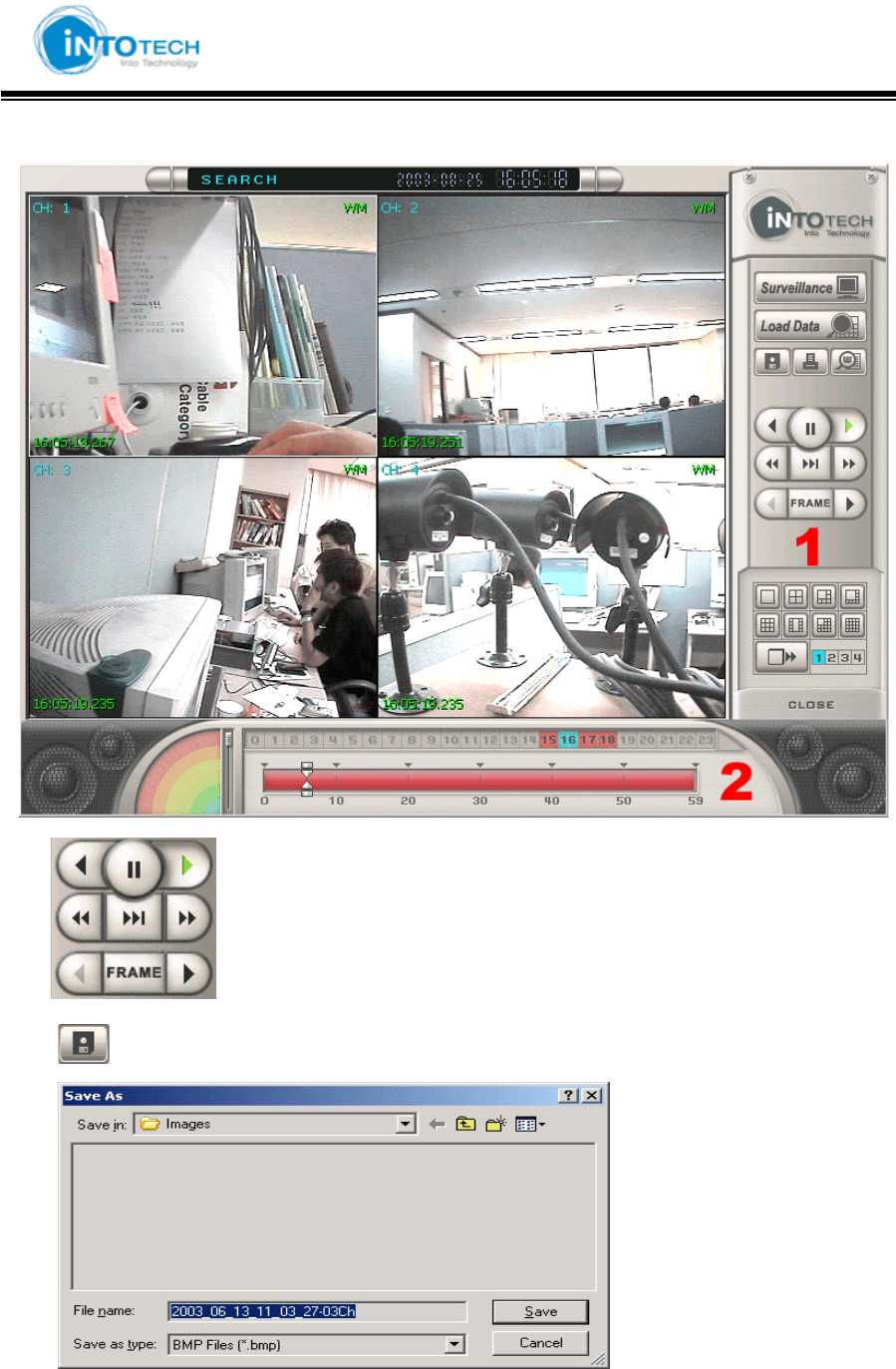
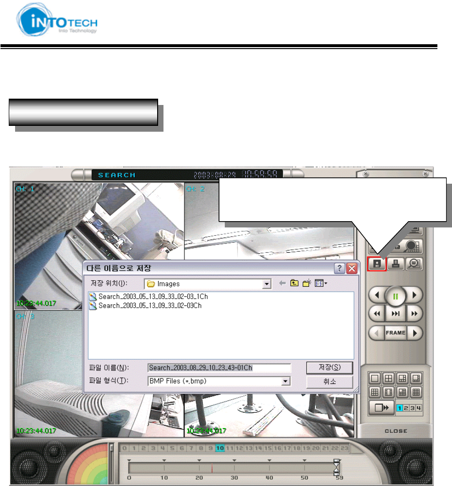
3-3. Search Screen Mode
1 : : Playback, Rewind, 2X Playback
: Save selected screen as image
Choose where to save image file and write file name
GGGGGGGGGGGGGGGGGGGGGGGGGGGGGGGSmartDVR Formula 2.0G
-58-G
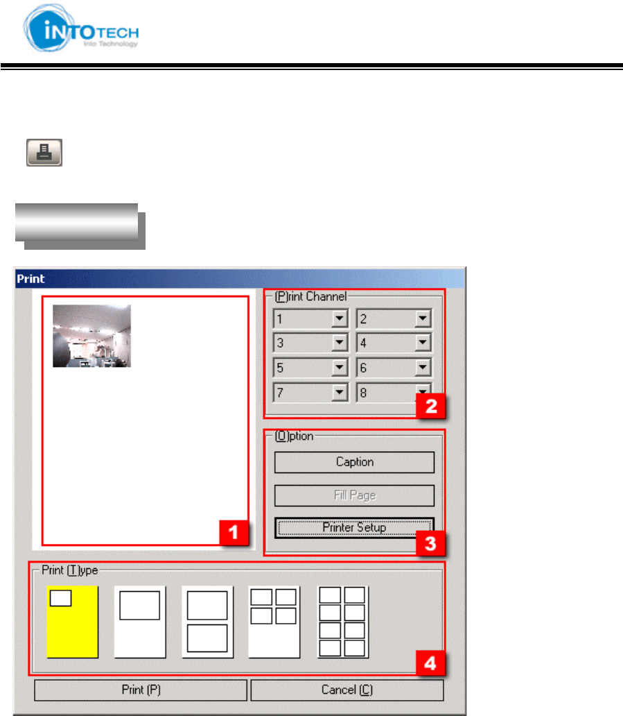
Print
= Print Images
1 : Preview Printing Images
2 : Able to print maximum of 8 selected camera channels
3 : Printer Setup Option
Print SetupG
GGGGGGGGGGGGGGGGGGGGGGGGGGGGGGGSmartDVR Formula 2.0G
-59-G
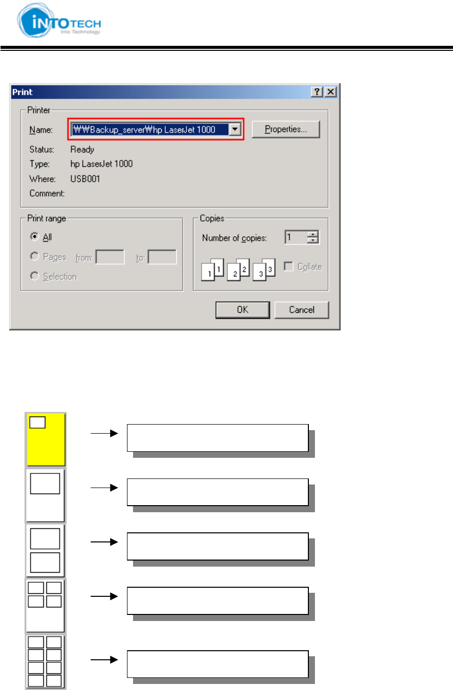
<Print Configuration>
Click the [OK] button to print
4 : 1 CH original copy size
1 channel image print out
1channel double size image print out
2 channels double size images print
4 channels images print out
8 channels images print out
GGGGGGGGGGGGGGGGGGGGGGGGGGGGGGGSmartDVR Formula 2.0G
-60-G
Watermark
1. Save image from search screen and view screen
- Next Page -
Direction to use Watermark
Save image by click save button after selec
t
channels
GGGGGGGGGGGGGGGGGGGGGGGGGGGGGGGSmartDVR Formula 2.0G
-61-G
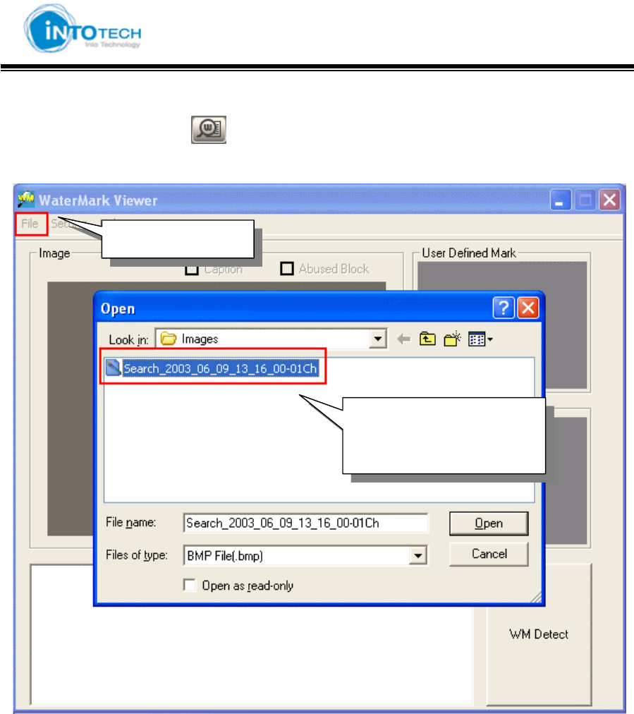
2. Click the watermark icon ( ) from searched Screen Mode
Open File to bring saved data
- Next Page -
Open File
Save image from Vie
w
Screen and Search Screen
GGGGGGGGGGGGGGGGGGGGGGGGGGGGGGGSmartDVR Formula 2.0G
-62-G
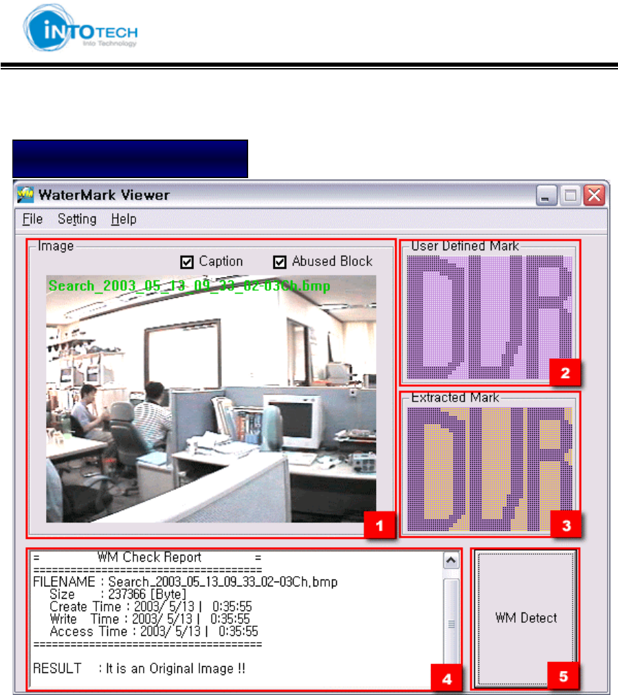
3.Click the [WM Detect] to watermark
1 : Show saved image.
2 : Show defined Mark by user at Configuration Mode
3 : Show Mark hidden in real image
4 : Show information related to image (Size, file formation time, modified time, process time)
RESULT : It is an Original Image !! = Show that images has not been tampered
5 : WM Detect button
Image has not been tampered
GGGGGGGGGGGGGGGGGGGGGGGGGGGGGGGSmartDVR Formula 2.0G
-63-G
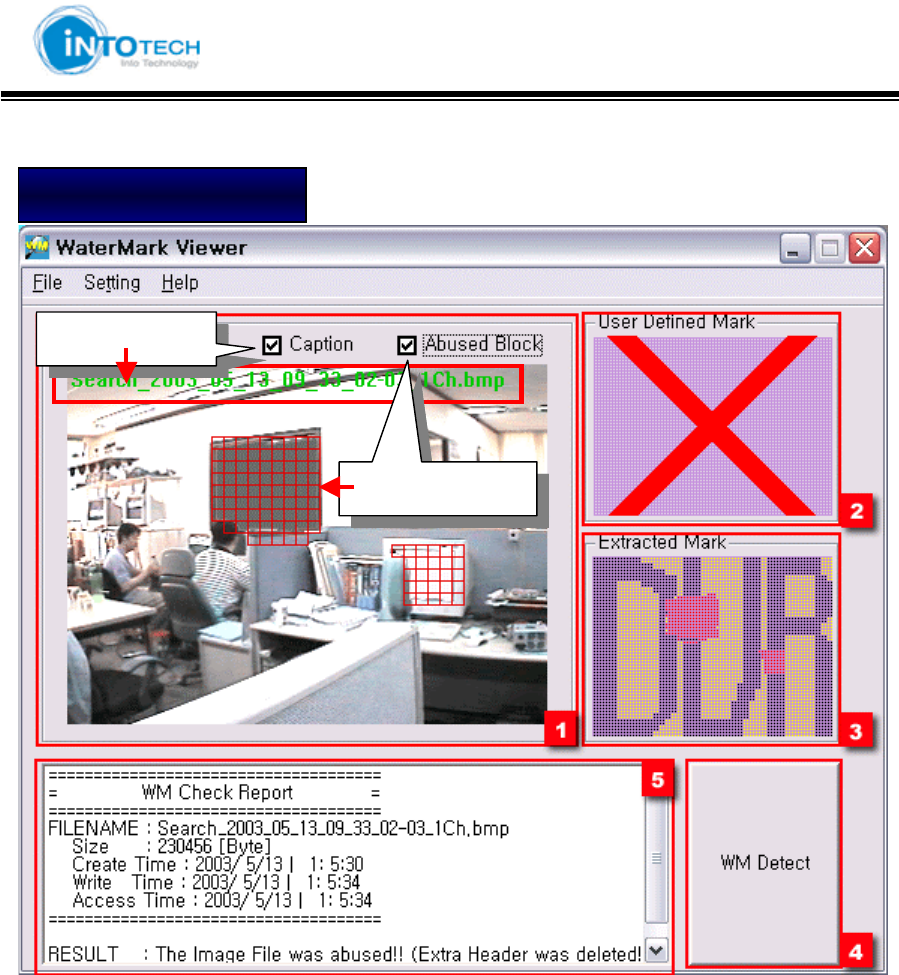
1 : Show saved image
2 : Show defined value of Watermark from Configuration Mode
Display X Mark as tampered image was detected
3 : Show Mark hidden in image (Display read color at tampered area)
4 : WM Detect Button
5 : Show image information size, reading time, writing time)
RESULT : The Image File was abused!! (Image has been tampered)
Image has been tampered
Tampered date
Tampered Area
GGGGGGGGGGGGGGGGGGGGGGGGGGGGGGGSmartDVR Formula 2.0G
-64-G
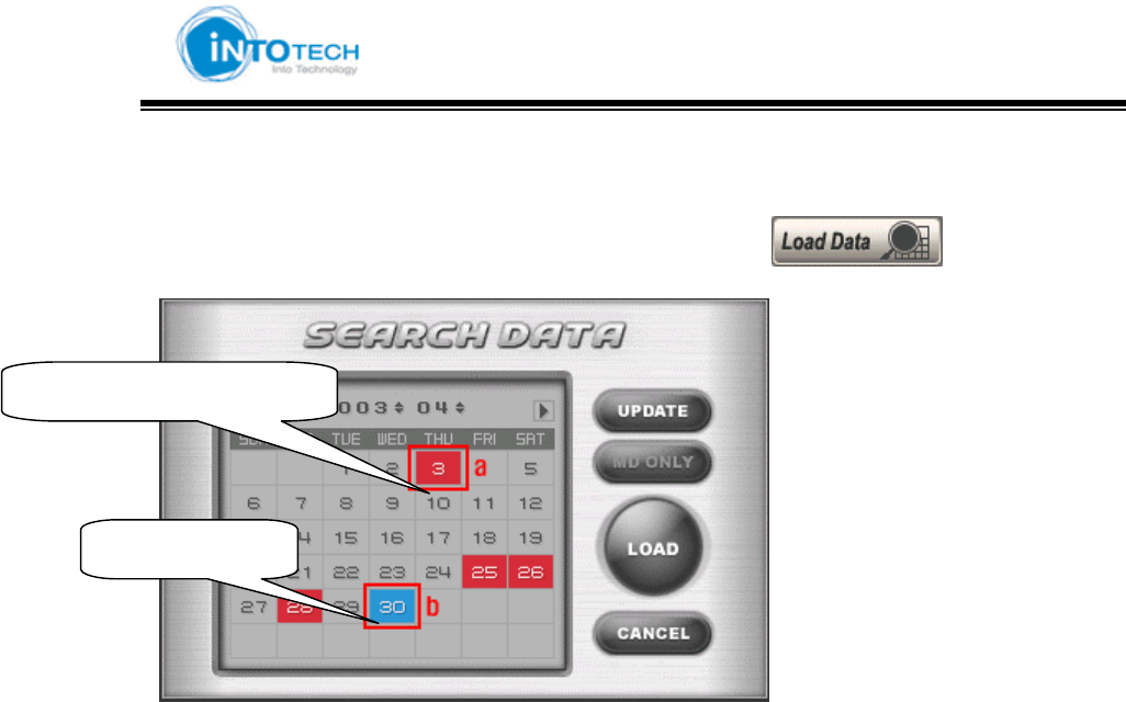
Search
1. Move to Search Screen Mode and then Click the calendar ( ) Icon
2. Select Search Date and then Click [Load] Button
- Next Page -
Date of saved data
Current Date
GGGGGGGGGGGGGGGGGGGGGGGGGGGGGGGSmartDVR Formula 2.0G
-65-G
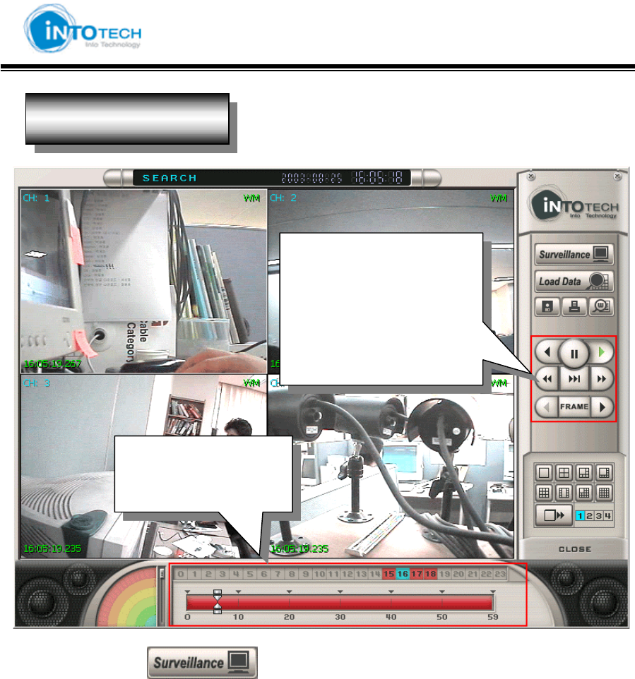
Click the view mode ( ) icon to return to Monitoring Screen (Main View Screen)
*Intotech Inc. is committed to ongoing product improvement; we therefore reserve the right to
change specifications without notice.
z Hour Search
z Minute Search
Playback saved images
2X Playback
Reverse Playback
Pause
Search data by each frame
Search Screen
GGGGGGGGGGGGGGGGGGGGGGGGGGGGGGGSmartDVR Formula 2.0G
-66-G
Warranty
Model SmartDVR Formula v2.0
Manufactured Date
Lot. No
Period of Warrant. 1 Year after purchasing
Purchased Date
It was a qualified item to pass a strict inspection and Quality control.
If it happen any problem, it will be guaranteed according to the
following written description.
1. The period of warrant is one year from the date of purchasing this item.
2. In case of deficit in manufacture, when happening trouble spontaneously,
We are ready to exchange or free-repairing refund or compensation.
3. If will fix up the system at Actual expense even though it in the period of
Warranty as following cases;
A. Mistake in using this system or trouble by handling carelessness
B. Trouble by repairing and reorganizing without our company is Permission,
Trouble to repair and reorganizing system by other companies Service
C. Troubles or Damages by due to the natural disaster Fire, earthquake, flood etc.
D. A case of Troubles by Customer’s attention of mistakes
4. If you would like to request the Application of A/S. Please contact below.
CAUTION: Changes or modifications not expressly approved by the manufacturer
responsible for compliance could void the user’s authority to operate the equipment
WAR NING
This device complies with part 15 of the FCC Rules. Operation is subject to the
following two conditions: (1) This device may not cause harmful interference, and (2)
this device must accept any interference received, including interference that may cause
undesired operation.
INFORMATION TO USER:
This equipment has been tested and found to comply with the limit of a Class B digital
device, pursuant to Part 15 of the FCC Rules. These limits are designed to provide
reasonable protection against harmful interference in a residential installation. This
equipment generates, uses and can radiate radio frequency energy and, if not installed
and used in accordance with the instructions, may cause harmful interference to radio
communications. However, there is no guarantee that interference will not occur in a
particular installation; if this equipment does cause harmful interference to radio or
television reception, which can be determined by turning the equipment off and on, the
user is encouraged to try to correct the interference by one or more of the following
measures:
1. Reorient / Relocate the receiving antenna.
2. Increase the separation between the equipment and receiver.
3. Connect the equipment into an outlet on a circuit difference from that to which
the receiver is connected.
4. Consult the dealer or an experienced radio/TV technician for help