Inovonics Wireless 3B6ECNCA Portable Alarm System User Manual 623754 00 DS100
Inovonics Wireless Corporation Portable Alarm System 623754 00 DS100
Contents
- 1. Users Manual Part 1
- 2. Users Manual Part 2
- 3. Users Manual Part 3
- 4. Users Manual Part 4
- 5. Users Manual Part 5
Users Manual Part 1

DS100 JobSite Security Portable Alarm System (Base Unit)
Système d'alarme mobile de sécurité des chantiers DS100 (Base)
Sistema de Alarma Portátil JobSite Security DS100 (unidad base)
INSTRUCTION MANUAL
GUIDE D’UTILISATION
MANUAL DE INSTRUCCIONES
INSTRUCTIVO DE OPERACIÓN, CENTROS DE SERVICIO Y PÓLIZA
DE GARANTÍA. ADVERTENCIA: LÉASE ESTE INSTRUCTIVO ANTES
DE USAR EL PRODUCTO.
Questions? See us on the World Wide Web at www.dewalt.com
Before returning this product call
1-800-4-DEWALT
IF YOU SHOULD EXPERIENCE A PROBLEM WITH YOUR DEWALT PURCHASE,
CALL 1-800-4 DEWALT
IN MOST CASES, A D
E
WALT REPRESENTATIVE CAN RESOLVE
YOUR PROBLEM OVER THE PHONE.
IF YOU HAVE A SUGGESTION OR COMMENT, GIVE US A CALL.
YOUR FEEDBACK IS VITAL TO THE SUCCESS OF D
E
WALT’S
QUALITY IMPROVEMENT PROGRAM.

i
IF YOU HAVE ANY QUESTIONS OR COMMENTS ABOUT THIS OR ANY DEWALT
TOOL, CALL US TOLL FREE AT: 1-800-4-DEWALT (1-800-433-9258)
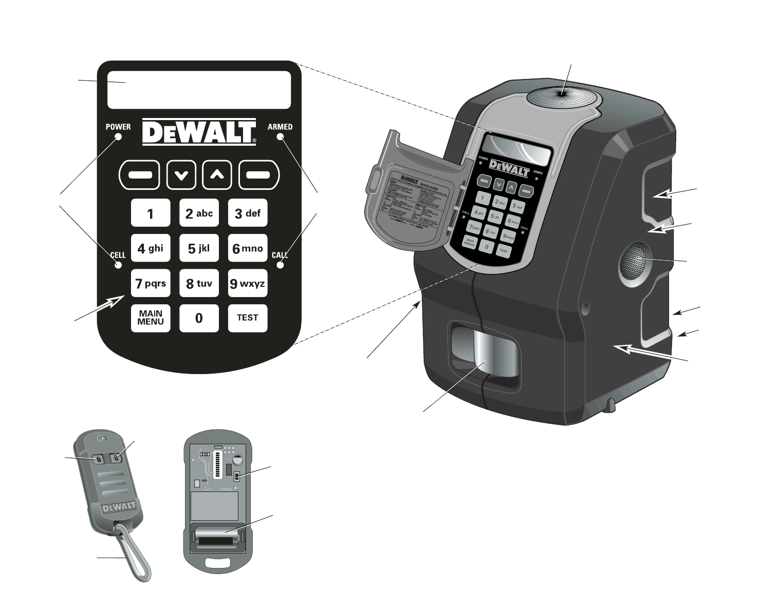
LCD DISPLAY
FUNCTION LEDs FUNCTION
LEDs
KEYPAD
INTERFACE
VIBRATION
SENSOR
MOTION
SENSOR
PHONE LINE
BACK-UP
8-HOUR
BATTERY
BACK-UP
AC ADAPTER
WIRELESS
SENSORS
RECEIVER-
TRANSMITTER
CELLULAR RADIO
RECEIVER-
TRANSMITTER
STROBE LIGHT
RESET BUTTON
BATTERY
SIREN
DS100
DS200
UNLOCK
LOCK
CARABINER
FIG. 1

English
ii
Table of Contents
Introduction......................................................................................................iii
Safety and Precautionary Information ....................................................iii
Limitations of the System ......................................................................iii
Regulatory and Safety Notices ..............................................................iv
Product Overview ............................................................................................1
Unique Features ......................................................................................1
Cellemetry®......................................................................................1
900 MHz, Frequency Hopping Spread Spectrum ..........................1
System Overview ............................................................................................1
DS100 Base Unit ....................................................................................1
Accessories..............................................................................................2
Prevention of False Alarms......................................................................2
During an Alarm ......................................................................................2
Initial Setup......................................................................................................3
Connecting the Equipment ......................................................................3
Placement of the Base Unit ............................................................3
Power and Telephone Connection ..................................................3
Programming for Initial Setup..................................................................4
Step One: Choosing a Language ....................................................4
Step Two: Set Time and Date..........................................................4
Step Three: Set Master Code..........................................................4
Step Four: Assign Devices ..............................................................5
Step Five: Test Range......................................................................6
Step Six: Add Users ........................................................................6
Step Seven: Monitoring Service ......................................................7
Basic Operations ............................................................................................7
Arming the System ..................................................................................7
Delays ..............................................................................................7
Using the Keypad ............................................................................7
Using the Key Chain Remote ..........................................................7
Arming Automatically........................................................................8
Disarming the System..............................................................................8
Entry Delays ....................................................................................9
Using the Keypad ............................................................................9
Using the Key Chain Remote ..........................................................9
Faults........................................................................................................9
How to View Faults ..........................................................................9
Clearing a Fault................................................................................9
Description of Fault Codes ............................................................10
Features & Options ......................................................................................10
System Settings ....................................................................................10
Wireless Device Maintenance ......................................................10
Change Master Code ....................................................................11
User Code Maintenance ................................................................12
Set Console Devices......................................................................13
Set Delay/Instant............................................................................13
Clear Settings ................................................................................14
Auto Arm ON/OFF..........................................................................14
Auto Arm Time Set ........................................................................15
Review Account..............................................................................15
Choose Language..........................................................................16
Set Date/Time ........................................................................................16
Review Event Log..................................................................................16
Locating the Event Log ..................................................................16
Description of Events ....................................................................17
Test ........................................................................................................17
Running a Test ..............................................................................17
Cellular Radio ................................................................................17
Phone Line ....................................................................................18
Console Devices ............................................................................18
Wireless Devices............................................................................19
External Sirens ..............................................................................19
If You Lose Your Master Code ..............................................................20
Turn System Off ....................................................................................20
Battery Maintenance..............................................................................20
Base Unit Battery ..........................................................................20
Device Batteries ............................................................................20
Contact ........................................................................................................20
Appendix........................................................................................................21
Coverage Map ......................................................................................21
List of Codes/Faults ..............................................................................22
Troubleshooting Guide ..................................................................................24
Glossary of Terms ........................................................................................25

Introduction
iii
SAVE THESE INSTRUCTIONS
General Safety Rules
WARNING: Read and understand all instructions. Failure to follow all
instructions may result in electric shock, fire, property damage and/or
serious personal injury or death.
WARNING: SERIOUS INJURY OR DEATH. This system was designed to provide pro-
tection of property only. Do not use this system to provide protection for life safety and from
fire. Any use other than that suggested in this instruction manual could cause injury or even
death. Not intended for residential use.
WARNING: SERIOUS INJURY OR DEATH. Do not use this system in hazardous
areas. This may include blasting areas and potentially explosive atmospheres. Sparks in
such areas could cause an explosion or fire resulting in bodily injury or even death. They
include but are not limited to fueling areas such as gas stations; fuel or chemical transfer
or storage facilities; vehicles using liquefied petroleum gas (such as propane or butane);
areas where the air contains chemicals or particles, such as grain, dust, or metal powders;
and any other area where one would normally be advised to turn off a vehicle engine.
WARNING: FIRE, ELECTRIC SHOCK OR ELECTROCUTION. Do not use an
extension cord unless it is absolutely necessary. Use of an improper extension cord or
an extension cord that has been worn or damaged could result in risk of fire, electric
shock or electrocution.
• An extension cord must have adequate wire size (AWG or American Wire Gauge)
for safety. The smaller the gauge number of the wire, the greater the capacity of the
cable, that is, 16 gauge has more capacity than 18 gauge. When using more than one
extension cord to make up the total length, be sure each individual extension cord con-
tains at least the minimum wire size.
Recommended Minimum Wire Size for Extension Cords
Total Length of Cord
25 ft. 50 ft. 75 ft. 100 ft. 125 ft. 150 ft. 175 ft.
7.6 m 15.2 m 22.9 m 30.5 m 38.1 m 45.7 m 53.3 m
Wire Size AWG
18 18 16 16 14 14 12
WARNING: BATTERIES – DANGER OF EXPLOSION, INJURY OR FIRE. The Base
Unit contains a lead acid battery. Do not incinerate as the battery can explode. The battery
cannot be accessed by a user; it is to be replaced and properly disposed of by D
E
WALT
authorized service only.
WARNING: BATTERIES – DANGER OF EXPLOSION, INJURY OR FIRE. For
the wireless devices, use only type CR-123 (CR-2 for Key Chain Remote) 3.0 Volt Li+
non-rechargeable batteries as specified by D
E
WALT. Carefully follow all instructions
and warnings on the battery label and package.
• Always insert batteries correctly with regard to the polarity (+ and -) marked on the
battery and the equipment. Never use a damaged or worn out battery.
• Never expose the battery terminals to any other metal object. This can short circuit
the battery.
• Avoid exposure to temperature extremes. When not in use, store the battery
uncharged in a cool, dark, dry place.
• Keep batteries out of reach of children.
• The battery is a self-contained unit. Do not attempt to open.
• Never dispose of a battery in a fire. Dispose of used batteries in accordance with local
regulations. Recycle batteries. Do not attempt to recharge batteries.
CAUTION: POTENTIAL EQUIPMENT MALFUNCTION OR FAILURE. Use only the
D
E
WALT power supplies marked for use with this equipment. If the cord is missing or
damaged, replace only with the D
E
WALT power supply specified for this equipment to
avoid product damage
CAUTION: POTENTIAL EQUIPMENT MALFUNCTION OR FAILURE. This equipment is
supplied with a wall mount power supply designed specifically to operate on 120V 60Hz.
Replace only with the D
E
WALT power supply specified for this unit.
CAUTION: POTENTIAL EQUIPMENT MALFUNCTION OR FAILURE. Do not use
near water. Damage to the equipment may occur. Equipment shall not be exposed to
dripping or splashing and no objects filled with liquids, such as vases, shall be placed
on the equipment.
CAUTION: POTENTIAL EQUIPMENT MALFUNCTION OR FAILURE. Do not operate
with a damaged power supply cord or plug. Damage to the equipment may occur. Protect
the power supply cord from being walked on or pinched particularly at plugs, convenience
receptacles, and the point where they exit from the Base Unit. Do not pull on cords or
cables. When unplugging the cord from an electrical outlet, grasp and pull the cord by the
plug. If a cord or plug is damaged, have it replaced immediately.
CAUTION: POTENTIAL EQUIPMENT MALFUNCTION OR FAILURE. To avoid potential
damage caused by a power surge, utilize a surge protector for both the power supply and
telephone connection.
CAUTION: POTENTIAL EQUIPMENT MALFUNCTION OR FAILURE. To ensure proper
operation, this equipment must be installed according to the enclosed installation instruc-
tions. To verify that the equipment is working properly and can successfully report an
alarm, this equipment must be tested immediately after installation and periodically there-
after according to the test instructions.
Important Notices
• This product is not user serviceable. There are no user serviceable parts inside the
product. Servicing at a D
E
WALT authorized service center is required to avoid damage
to static sensitive internal components.
• The Base Unit is for indoor use only. All wireless devices, unless specifically noted, are
intended for indoor use.
• Only use sensors, Mounting Brackets, and accessories specified by D
E
WALT. Use of
others may be incompatible and interfere with system operation.
• Clean only with a dry cloth.
• Although the noise level and duration of the chime and siren are below OSHA limits, the
loud noise from the sirens and chimes may startle people on the site.
• Check with local authorities to be sure that a monitoring service can be used.
Registration may be necessary and fees may be involved.
•D
E
WALT is a registered trademark of D
E
WALT Industrial Tool Co., 701 East Joppa
Road, Baltimore, MD, USA. All other trademarks in this manual are the properties of
their respective owners.
Limitations of System
Although this system is designed as a security system, it does not guarantee protection
against burglary or other emergencies. Any alarm system is subject to compromise or fail-
ure-to-warn for a variety of reasons including, but not limited to, the following:
• An intruder may gain access through unprotected openings. An intruder with criminal
intent, technical knowledge or jamming devices may bypass the system.
• This system will not operate without power. The equipment is primarily powered by AC
and utilizes a battery as back-up power. If the AC power supply is off and the back-up
battery is uncharged, the equipment will not operate.
• The wireless devices for this system, such as sensors and remotes, are powered by
non-rechargeable batteries. If the batteries are missing, installed incorrectly or dead,
the battery-operated devices will not function properly.
• Signals sent by wireless devices may be blocked or reflected by metal before they
reach the receiver. Even if the signal path has been recently checked during a routine
test, blockage can occur if a metal object is moved into the path.

English
iv
• A telephone line, either cellular or landline, is needed to transmit alarm signals to the
monitoring system. If reception is not available, telephone lines are out of service, or the
telephone company makes changes to its facilities, the outgoing call cannot be placed.
• This equipment uses an RJ-11 jack to connect to the telephone network. If another
device, such as a telephone, fax or modem, is utilizing the connected phone line, this
equipment will not interrupt the device currently in use.
• If utilizing a landline, high-speed data formats such as DSL could affect the ability to
reach the monitoring system. You may need to install a filter provided by your DSL
company. Even with a filter, there is still a possibility the equipment will not be able to
communicate with the monitoring system.
• Wireless devices have a limited range. If they are placed out-of-range, they will not be
able to send or receive signals with the Base Unit.
• Passive Infrared Motion Detectors can only detect intrusion within the designated
ranges as diagrammed in their instruction manual. Passive Infrared Motion Detectors
do not provide volumetric area protection. They do create multiple beams of protection
and intrusion can only be detected in unobstructed areas covered by those beams.
They cannot detect motion or intrusion that takes place behind walls, ceilings, floors,
closed doors, glass partitions, glass doors or windows. Mechanical tampering,
masking, painting or spraying of any material on the mirrors, windows or any part of
the optical system can reduce their detection ability. Passive Infrared Motion Detectors
sense changes in temperature; thus, as the ambient temperature of protected area
approaches the temperature range of 90º to 105ºF (32º to 40ºC), the detection
performance can decrease.
• This system is a self-installed security system. Carefully follow all instructions.
Improper installation may compromise the operation of this equipment.
• This alarm system should be tested regularly to make sure all sensors and transmit-
ters are working properly.
• Even if the system responds to an intrusion as intended, the users may have insufficient
time to protect their assets and property. To provide the best support, customer service
must be notified of any change of site and device additions or deletions. Even with mon-
itoring, the authorities may not respond appropriately.
• Warning devices, such as sirens and strobe lights, may not alert people if no one is
in range or not on the premises. Persons may not hear the warning if the alarm is
muffled from a radio, operating equipment, appliances or by passing traffic. Alarm
warning devices, however loud, may not warn hearing-impaired people. Similarly, the
strobe light may not be seen by vision-impaired people.
• In the event of an intrusion, the system is designed to contact the monitoring system.
Even if a call is placed, the user may not be able to respond quickly enough.
• Despite advanced design and regular testing, this equipment, like other electrical
devices, is subject to component failure.
• Installing this system with a monitoring service may make one eligible for lower
insurance rates, but a security system is not a substitute for insurance.
REGULATORY NOTICES
Federal Communications Commission (FCC) Part 15
Statement
• This equipment (Base Unit and Key Chain Remote) has been tested and complies with
Part 15 of the FCC Rules. Operation is subject to the following two conditions: (1)
This device may not cause harmful interference, and (2) the device must accept
any interference received, including interference that may cause undesired
operation.
• If this equipment does cause harmful interference to radio or television reception,
which can be determined by placing the equipment in standby mode, try to correct the
interference by one or more of the following measures:
1. Reorient the antenna of the radio/TV experiencing the interference.
2. Relocate the Base Unit with respect to the radio/TV.
3. Move the antenna leads away from any wire that runs to the Base Unit.
4. Plug the Base Unit into an outlet on a different electrical circuit from the radio/TV
experiencing the interference.
5. If necessary, consult DEWALT or an experienced radio/TV technician for help.
6. Additional suggestions can be found in the following booklet prepared by the Federal
Communications Commission “Interference Handbook” This book is available from
the U.S. Government Printing Office, Washington, DC 20402.
• Any changes or modifications to the equipment, not specifically approved by DEWALT,
can void the user’s authority to operate the equipment.
FCC ID: HCQ3B6ECNCA (Base Unit) and
FCC ID: HCQ3B6ETRT2M (Key Chain Remote)
Federal Communications Commission (FCC) Part 68
Statement
• This equipment (DS100) complies with Part 68 of the FCC Rules and the requirements
adopted by the ACTA. Located on the equipment (DS100) is a label that contains,
among other information, a product identifier that has the format US: AAAEQ##TXXXX.
If requested, this information must be provided to the telephone company.
• The REN is used to determine the number of devices which may be connected to a
telephone line. Excessive RENs on a telephone line may result in devices not ringing
in response to a call. In most, but not all areas, the sum of all REN devices should not
exceed an REN of five (5.0). To determine the REN for your calling area, contact the
telephone company. The REN is part of the product identifier that has the format US:
AAAEQ##TXXXX. The digits represented by ## are the REN without a decimal point
(e.g., 03 is a REN of 0.3).
• This equipment (DS100) uses an RJ-11 jack to connect to the telephone network. If
another device, such as a telephone, fax or modem, is utilizing the connected phone
line, this equipment will not interrupt the device previously in use.
• If this equipment (DS100) causes harm to the telephone network, the telephone com-
pany will notify you in advance that temporary discontinuance of service may be
required. If advance notice is not practical, they will notify you as soon as possible. You
will be advised of your right to file a complaint with the FCC if you deem necessary.
• The telephone company may make changes in its facilities, equipment, operations or
procedures that could affect the operation of the equipment (DS100). You will be given
advance notice in order to maintain uninterrupted service.
• If trouble is experienced with this equipment (DS100), please call 1-800-4-DEWALT
(1-800-433-9258) for repair and warranty information. If the trouble is causing harm to
the telephone network, the telephone company may request you remove the equip-
ment from the network until the problem is resolved.
• There are no user serviceable components in this equipment (DS100). All necessary
repairs must be made by a DEWALT authorized service center.
• This equipment (DS100) may not be used on coin service provided by the telephone
company.
• Connection to party lines is subject to state tariffs. Contact the state public utility com-
mission, public service commission, or corporation commission for information.
Industry Canada
•NOTICE: this equipment meets the applicable Industry Canada Terminal Equipment
Technical Specifications. This is confirmed by the registration number. The abbrevia-
tion, IC, before the registration number signifies that registration was performed based
on a Declaration of Conformity indicating that Industry Canada technical specifications
were met. It does not imply that Industry Canada approved the equipment.

Introduction
v
• This certification means that the equipment meets certain telecommunications network
protective, operational and safety requirements as prescribed in the appropriate
Terminal Equipment Technical Requirements documents. The Department does not
guarantee the equipment will operate to the user’s satisfaction.
• The RINGER EQUIVALENCE NUMBER (REN) for this terminal equipment is noted on
the Base Unit label. The REN assigned to each terminal equipment provides an indi-
cation of the maximum number of terminals allowed to be connected to a telephone
interface. The termination on an interface may consist of any combination of devices
subject only to the requirement that the sum of the Ringer Equivalence. Numbers of all
the devices does not exceed five (5.0).
• Before installing this equipment, users should ensure that it is permissible to be con-
nected to the facilities of the local telecommunications company. The equipment must
be installed using an acceptable method of connection.
• The customer should be aware that compliance with the above conditions may not pre-
vent the degradation of service in some situations.
• Repairs to certified equipment should be coordinated by a representative designated
by the supplier. Any repairs or alterations made by the user to this equipment or equip-
ment malfunctions may give the telecommunications company cause to request the
user to disconnect the equipment.
• Users should ensure for their own protection that the electrical ground connections of
the power utility, telephone lines and internal metallic water pipe system, if present, are
connected together. This precaution may be particularly important in rural areas.
•CAUTION: Users should not attempt to make such connections themselves, but should
contact the appropriate electric inspection authority, or electrician, as appropriate.
• The Load Number (LN) assigned to each terminal device denotes the percentage of
the total load to be connected to a telephone loop which is used by the device, to pre-
vent overloading. The termination on a loop may consist of any combination of devices
subject only to the requirement that the total of the LNs of all the devices does not
exceed 100.
IC: 2309A-ECNCA (Base Unit) and
IC: 2309A-ETRT2M (Key Chain Remote)
Warnings
For your convenience and safety, the following warning labels are on the Base Unit and
Key Chain Remote:
DS100 BASE UNIT
• To reduce the risk of injury, user must read and understand Instruction Manual.
• Use only with DEWALT authorized power sources designated for this product.
• Not for personal protection.
• Contains Lead-Acid battery. Must be recycled or disposed of properly. See Instruction
Manual.
DS200 KEY CHAIN REMOTE
• To reduce the risk of injury, user must read and understand Instruction Manual.
FREE WARNING LABEL REPLACEMENT: If your warning labels become illegible or are
missing, call 1-800-4-DEWALT for a free replacement.

English
1
Unique Features
This system offers several features unique to most security systems.
CELLEMETRY®
Cellemetry® is a patented two-way wireless data network that uses standard cellular infra-
structure to transport small packets of communication messages throughout North America.
The technology is currently used on Verizon, AT&T and Cingular cellular networks
providing a near seamless network on a proven cellular network architecture.
This technology is proven and reliable using the digital control channels, not voice channels.
Messages traverse existing AMPS cellular network infrastructure (like roaming cell phones).
The control channels are more robust than the voice channels because of the use of digital
technology, higher transmission power offering better coverage, and cost effective use due
to small amounts of information being transmitted at a time. The analog cellular network is
one of the largest radio networks in the world with over 200,000,000 packets of data trans-
mitted daily in North America. This only represents 10% of the maximum control channel
capacity.
The DS100 JobSite Security Portable Alarm System (Base Unit) contains a 1.2 watt
cellular data radio providing rapid communications in less than 1 second. This technology is
superior to phone line monitoring because phone lines are inherently vulnerable, readily
identifiable, and thieves potentially cut them before entering a site.
This product can be used virtually anywhere in North America where cellular coverage is
available, with no roaming fees. See the Coverage Map in the Appendix.
This notification happens instantly and will provide direct feedback when system is armed.
This unique feature helps to provide the ultimate in protection of commercial assets and
rapid response notification.
900 MHZ, FREQUENCY HOPPING SPREAD SPECTRUM
Spread Spectrum is a frequency-hopping communication technique that sends redundant
messages across a bandwidth of at least 10 MHz to provide immunity from interference
and help ensure reliable communication. This communication between the Base Unit and
sensors provides coverage of up to 2000' enabling superior range and reliability. Virtually
all 300MHz systems send information on one narrow band channel. Any “in-band” interfer-
ence can result in missed signals.
DS100 JobSite Security Portable Alarm System
(Base Unit)
The DS100 JobSite Security Portable Alarm System is a portable self-contained alarm
system that can be easily moved from site to site. This system includes a built-in motion
sensor, vibration sensor, siren, strobe, battery back-up, LCD display, key pad interface,
cellular radio receiver-transmitter, wireless sensors receiver-transmitter, phone connector
and AC adaptor.
SYSTEM OVERVIEW
PRODUCT OVERVIEW
ELECTRONIC CHIME TONE
When typing on the keypad, there will be a chime that indicates the key was pressed.
KEY PAD INTERFACE
Refer to Figure 1 at the beginning of this manual.
NAVIGATING THROUGH THE SCREENS
The Base Unit has an LCD screen that will communicate the current state of the unit and
messages will scroll across the screen. Below the screen are four keys that align with avail-
able options. Choose the appropriate key.
·
DS200 KEY CHAIN REMOTE CONTROL
The DS200 Key Chain Remote Control offers the benefit of easy one-touch arming or
disarming of the system from a range of up to 2000'. The remote uses 900MHz spread
spectrum communication to provide superior range and reliability. The LED feedback
light notifies the user when a signal is being sent to the Base Unit. Also, a convenient
carabiner clip is included for versatility.
The DS200 Key Chain Remote Control uses a CR-2 3.0 Volt Lithium battery.
To arm the system, press LOCK ( ) once. To disarm the system, press UNLOCK ( )
once.
LINE 1
LINE 2
ACTUATING
BUTTONS
DOWN UP
LEFT RIGHT
LED SOLID BLINKING OFF
POWER Primary power • Primary power supply No unit power
source is present missing (steady flashes); and no battery
• Low battery (series of two power
flashes); or
• Standby state (one flash
every 5 seconds)
ARMED System is armed On an exit or entry delay System is
disarmed
CELL Cellular signal Cellular signal No Cellular
is strong is weak signal
CALL Call is complete Call is in progress No activity
(will remain solid
for 30 seconds)
System Overview
2
Accessories
Additional accessories for use with the DEWALT JobSite Security Portable Alarm System
are available at extra cost from your local dealer or authorized service center. If you need
assistance in locating any accessory for JobSite Security System, contact: SITELOCK LLC,
626 Hanover Pike, Hampstead, MD 21074, visit www.dewalt.com or call customer service
at 1-800-4-DEWALT (1-800-433-9258).
CAUTION: The use of any other accessory not recommended for use with the D
E
WALT
JobSite Security Portable Alarm System could be hazardous.
Key Chain Remote Control: Up to six Key Chain Remotes may be added to your system.
Alarm System Mounting Bracket: The bracket is used for mounting the Base Unit and
includes a lock and key for securing the Base Unit once mounted. The molded-in
mounting holes provide for easy installation in corners or flat against a wall.
Indoor Motion Sensor (PIR): This sensor provides a 50' range of protection with
advanced digital scanning to recognize human movements and size to help prevent
false alarms. Recommended for use in enclosed areas, offices, climate controlled stor-
age and monitoring interior spaces.
Door/ Window Contact Sensor: This sensor is used for monitoring the opening of objects
like doors or windows or a gap of up to 3/8". Recommended for use in enclosed areas,
offices, climate controlled storage and monitoring interior spaces.
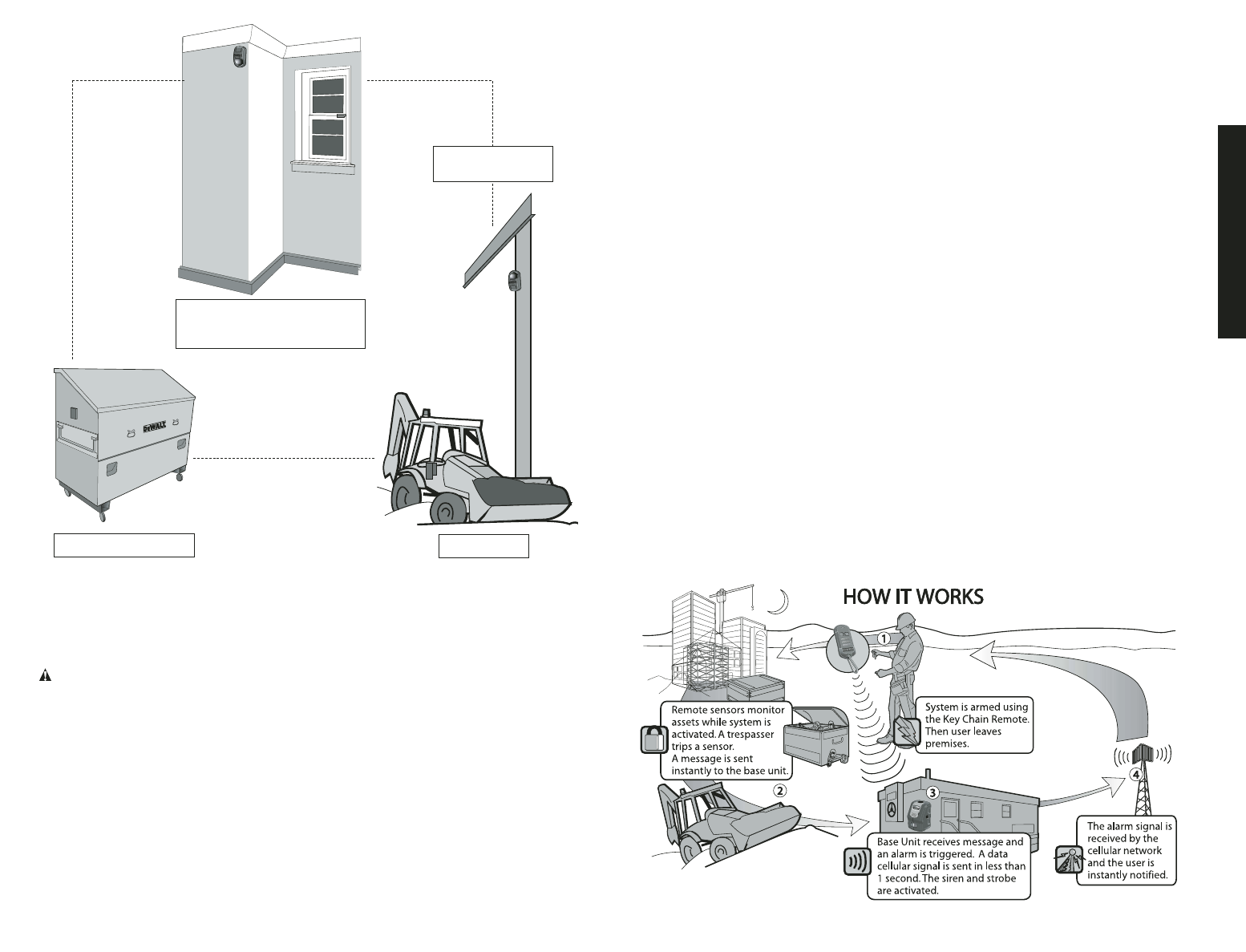
OUTDOOR
MOTION SENSOR
INDOOR MOTION SENSOR
AND
DOOR/WINDOW SENSOR
CONTAINER SENSOR CABLE LOCK
JobSite Security Cable Lock: A unique sensor that enables securing of assets by
wrapping a cable through mobile equipment, containers, materials, gates or other
remote assets for protection. Also provides a location for a standard padlock
(not included)
providing added security.
Container Sensor: A unique sensor that enables monitoring of remote metal containers
by measuring vibration. Recommended for use on steel containers, large tool boxes
and tool storage boxes.
Outdoor Motion Sensor (PIR): This sensor is used for monitoring an outdoor area and
is recommended to monitor enclosed outside areas or non-temperature controlled
environments.
Prevention of False Alarms
The majority of alarms that occur are false. These situations happen every day due to user
error, incorrect installation or improper maintenance of the system. False alarms will limit
the responsiveness to the system, and become a general inconvenience. As the number
of false alarms increases, authorities have become less apt to respond to alarm systems
due to this problem. Many of these situations can be avoided by following some very sim-
ple practices.
• Ensure all users are properly trained on the operation of the system.
• Always turn off the system with the Key Chain Remote Control before entering protected
area.
• Lock all protected doors, windows or any other asset attached to a sensor.
• Check that motion detectors are not obstructed. Do not allow sources of heat or sound
in range of the motion or vibration sensors.
• Check that premises are cleared and assets secured before setting the system.
• Turn off all noise sources – radios, compressors, generators, heavy equipment, etc.
• Know how to cancel an alarm or turn off the system before activating.
• If a false alarm is tripped call customer service immediately.
• Test the system on a monthly basis to ensure proper functioning.
• Check cellular signal, power supply, and that sensors are secured on a daily basis.
• Keep the Base Unit plugged in to the wall outlet. When the back-up battery drops below
a certain level, the system will notify the the user through the monitoring service.
During an Alarm
English
3
If the system is armed and it receives either an
Instant
alarm signal from a sensor or
the entry delay time on a sensor has expired, the system shall enter the Alarm State
for 8 minutes.
MONITORING
A call is immediately placed to the monitoring service. The CALL LED will flash to indi-
cate a call is in process. If a different sensor becomes unsecured during the current
8-minute window, another call will be placed. If the cellular radio signal is not available,
it is recommended to use a telephone connection as a back-up.
BASE UNIT
If the strobe and siren are enabled, they will be activated. The CALL LED will be solid
when the call was successful. The LED message will extinguish after 30 seconds.
EVENT LOG
As an alarm occurs, the event is recorded in the event log. The log will record the type
of event, the date and time. To find details on the event log, see Review Event Log.
After operating in the Alarm State for 8 minutes, the system shall return to arming. To
exit the Alarm State enter a valid user code or press the disarm button on the Key
Chain Remote.
Before proceeding, the system will display the alarm that occurred. See Faults for
more information on viewing the fault, clearing the fault and resuming normal status.
Connecting the Equipment
• Placement of the Base Unit
• Physical Setup
PLACEMENT OF THE BASE UNIT
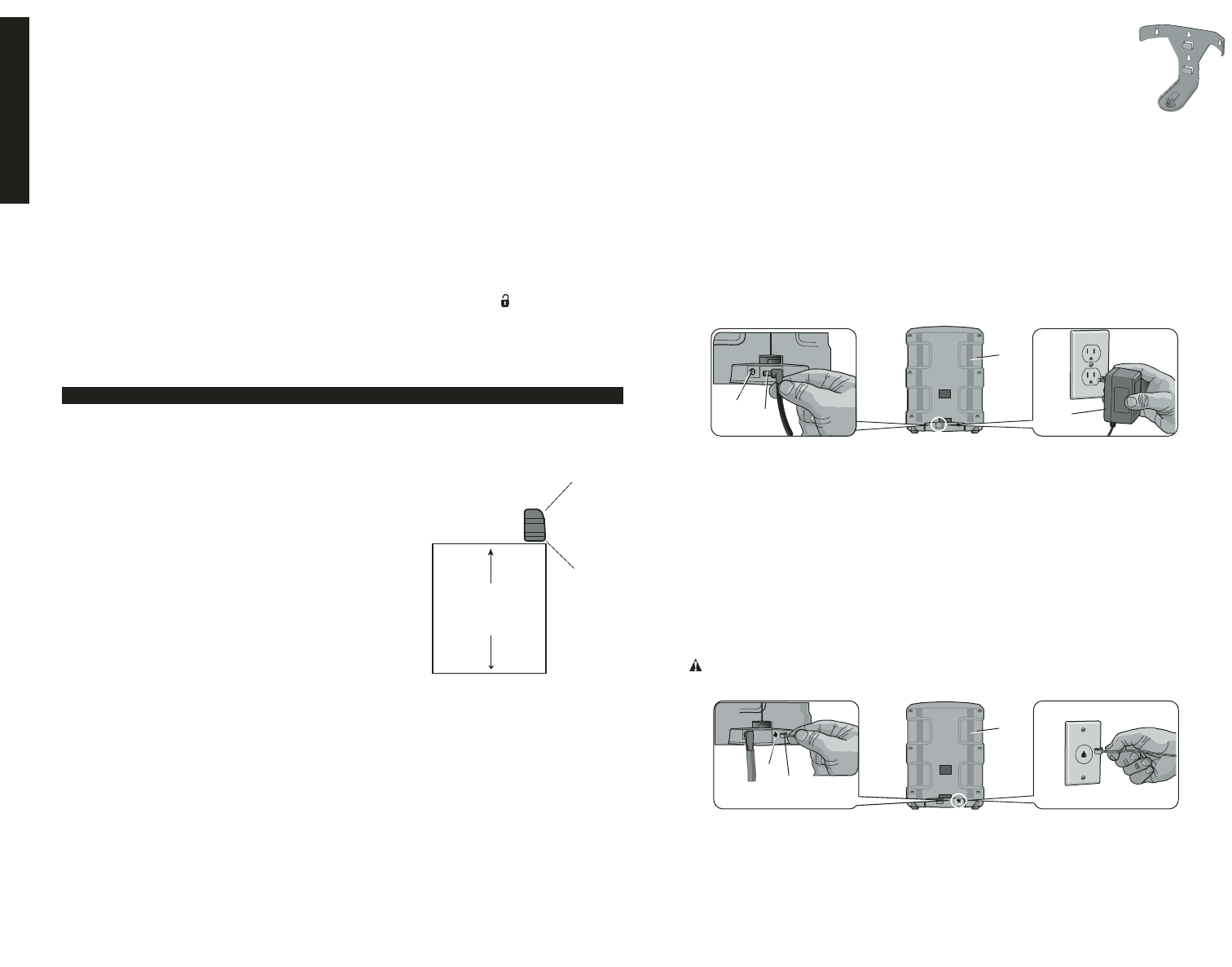
Height
The recommended height for the Base Unit is
between 3' (.9m) to 6' (1.8m) off the floor. Any
height outside of this range will decrease the sen-
sitivity of the motion detector in the Base Unit. Be
sure that the unit is placed at a height such that any
person accessing the system can easily operate
the keypad.
Edge
If using the Base Unit on a desk, shelf or any other
fixed object, placing the unit near the edge will
maximize the range of the motion detector.
Direction
Face the Base Unit in a direction so that intruders move across the detection zone,
rather than toward or away from the motion sensor in the Base Unit.
Vibration
The Base Unit contains a vibration sensor. Mount the Base Unit in a location that is
not subject to vibration during the armed state. If the system is armed and both the
motion sensor and vibration sensor are activated, an alarm is sent instantly.
Heat
The motion detector inside the Base Unit is sensitive to heat. To prevent false alarms,
avoid placing in direct or reflected sunlight, or near objects that can be heated quick-
ly by sunlight. Do not place the Base Unit facing the windows. Do not place the unit
near heating or cooling sources, like heater ducts, air conditioners, or space heaters.
SENSOR
RANGE
3' to 6'
(.9m to 1.8m)
INITIAL SETUP
The DEWALT Mounting Bracket (DS001) is recommended
for mounting and to secure the Base Unit to a wall or corner. The
Mounting Bracket must be purchased separately.
CAUTION: POTENTIAL EQUIPMENT MALFUNCTION OR FAIL-
URE. This equipment is for indoor use only. Placement in outdoor
conditions can damage the unit.
POWER AND TELEPHONE CONNECTION
The unit must be connected to a power source to begin set up. This will charge the
internal battery. It is recommended that the Base Unit be connected to a telephone line
to provide back-up in the event of cellular reception loss.
Power Connection
CAUTION: POTENTIAL EQUIPMENT MALFUNCTION OR FAILURE. Use only
D
E
WALT power supplies marked for use with this product. Other power supplies may
damage the product.
NOTE: The battery will take up to 24 hours to charge completely. The battery is
designed to be a back-up source of power for up to 8 hours. To avoid draining the bat-
tery, do not use an outlet that is controlled by a wall switch.
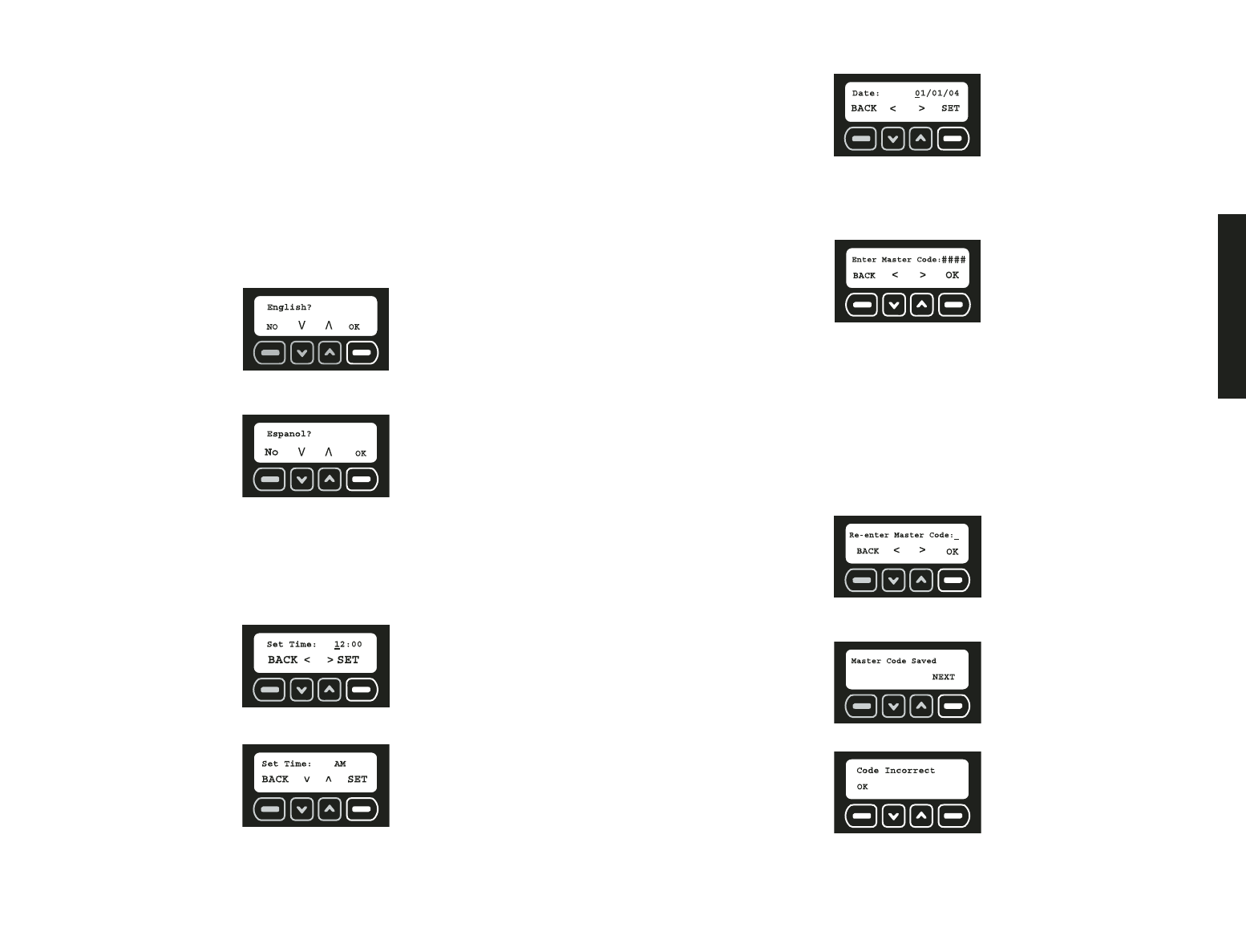
1. Connect the power supply connector (A) to the receptacle (B) in the back of the
Base Unit (C).
2. Insert the 120V plug of the power supply (D) into the wall receptacle.
3. The power light will indicate that the system has power.
IMPORTANT: After connecting the unit, the alarm system will not be active until
the initial setup is complete, the sensors are programmed and DEWALT customer
service registers the system.
Telephone Connection
NOTE: The connection to the telephone line is designed to be a back-up source of
communication. When the cellular radio does not have a connection (the Cell LED is
not lit), the telephone connection will be used.
CAUTION: To prevent damage to the system, use a telephone communications
surge protector.
1. Connect the telephone plug (E) to the jack (F) in the back of the Base Unit (C).
2. Insert the other end of the telephone cord into the wall singular modular phone jack.
Do not use a modular phone jack that communicates with multiple lines such as a
phone system in which multiple phone numbers ring into a single telephone. This
system will not work on a pay telephone line.
E
F
C
A
B
C
D
Initial Setup
4
Programming for Initial Setup
After power is supplied to the Base Unit, a setup sequence will enable customization of the
system.
SEVEN EASY STEPS:
1. Choosing a Language
2. Set Time and Date
3. Set Master Code
4. Assign Devices (have Key Chain Remote, sensors and batteries ready)
5. Test Range
6. Add Users
7. Monitoring Service
STEP ONE: CHOOSING A LANGUAGE
Choose from three different languages: English, French or Spanish.
A language will be displayed on the screen when power is supplied to the Base Unit.
1. To continue in English, select OK.
2. To choose another language, use the arrow keys to find the correct language.
3. When the desired language is displayed, select OK.
STEP TWO: SET TIME AND DATE
Time and date MUST be set during the initial setup. The event log will list all events accord-
ing to date and time.
1. Using the numbers on the keypad, set the clock to the appropriate time, changing
hours first, then minutes. The character that is being changed will be underlined. To
move back a character, use the down arrow. To move forward a character, use the up
arrow. Select SET.
2. Choose AM or PM. The up and down arrows are used to toggle between AM and PM.
Select SET.
3. Using the numbers on the keypad, set the date. The character that is being changed
will be underlined. To move back a character, use the down arrow. To move forward a
character, use the up arrow. Select SET
STEP THREE: SET MASTER CODE
A master code MUST be selected. This code can be changed; however, it is the ONLY
code that can be used to make programming changes and clear a fault.
The Enter Master Code screen will appear after the date is set.
1. Using the numbers on the keypad, enter a four digit master code. The character that
is being changed will be underlined. To move back a character, use the down arrow.
To move forward a character, use the up arrow.
NOTE: Only the master code can be used to make programming changes. Be sure
to choose a code that is easy to remember or write this code in a secure location away
from the system. If you lose this code, you will need to have it reset through customer
service. See If You Lose Your Code for details. All other users will have access to
the arming and disarming features only. To add a new user see Add Users.
2. After entering the master code, select OK.
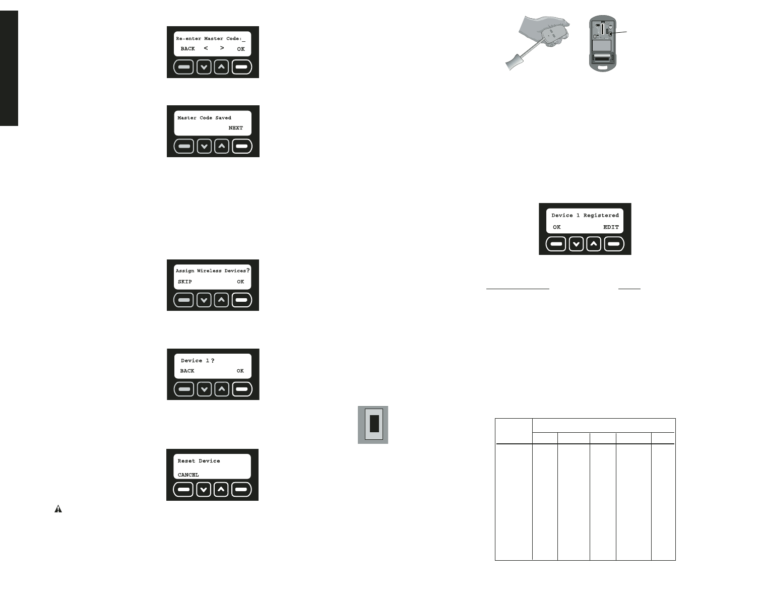
3. Re-enter the master code to confirm. Again, using the numbers on the keypad, enter
the four digit master code. Select OK.
4. If the master codes match, the screen will indicate that the master code has been
saved. Select NEXT.
NOTE: If the codes do not match, the screen will display Code Incorrect.
If Master Codes Do Not Match
1. Select OK.
English
5
2. Re-enter the master code. Select OK.
3. If the codes match, the screen will indicate that the master code has been saved.
Select NEXT.
STEP FOUR: ASSIGN DEVICES
Up to 48 sensors and 6 Key Chain Remotes can be assigned. As each sensor is added, it
will communicate with the Base Unit to notify the user of an intrusion. Additional sensors
and remotes can be programmed at any time after the initial setup. Refer to Wireless
Device Maintenance.
NOTE: Each device (Key Chain Remote or sensors) must have batteries to operate. Refer
to the instruction manual for each device to determine the type of battery required.
1. The Assign Wireless Devices screen will appear after setting the master code. To add
sensors and Key Chain Remotes, select OK.
2. The device number of the next available device will be displayed. Add the Key Chain
Remote included with the Base Unit as the first device. Select OK. The device will not
register until OK is selected and then the device reset button is pressed and released.
NOTE: Each device has a reset button that must be pressed and
released. To locate the reset button, refer to the instructions for each
particular device.
3. Reset the device.
CAUTION: Do not touch the electronic components inside the devices as they are
static sensitive.
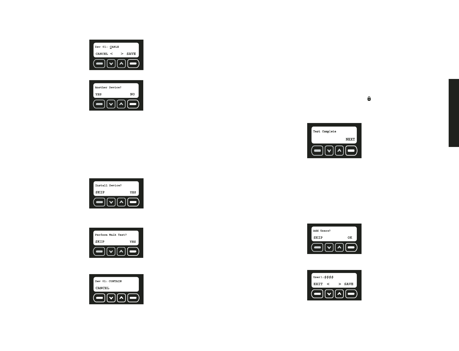
TO ACCESS THE RESET BUTTON ON THE KEY CHAIN REMOTE
a. Using a flat screwdriver, open the housing. Insert the screwdriver about .25" (6mm)
at the tab on the top of the unit. Pry downward on the handle of the screwdriver until
the latch holding the cover to the housing base releases.
RESET
BUTTON
b. Install the battery using the polarity (+ and -) markings on the battery and equipment.
Do not use excessive force. If the battery does not fit, check to make sure that it
matches the polarity markings.
c. When prompted by the Base Unit to RESET DEVICE, press the reset
button located inside the Key Chain Remote to register the device. After registering
the Key Chain Remote, replace the cover.
4. Only 48 sensors and 6 Key Chain Remotes can be assigned, if there are no slots avail-
able, the screen will display ALL DEVICES IN USE. When the device has been regis-
tered, the screen will indicate which type of device has been registered. This descrip-
tion is the default description set at the factory. To provide further detail, such as the
location of the device, the description can be changed by selecting EDIT. To keep the
default description, select OK and move to step 7.
NOTE: If the device does not register when you press the reset button, see the
Troubleshooting Guide for more detailed information.
List of Devices Code
Indoor Motion Sensor – PIR I.MOTION
Door / Window Contact Sensor DOOR/WIN
JobSite Security Cable Lock CABLE
Container Sensor CONTAIN
Outdoor Motion Sensor – PIR O.MOTION
Key Chain Remote KEYCHAIN
5. To edit the device description using the keypad, type a description of up to 8 characters.
The character that is being changed will be underlined. To move back a character, use
the down arrow. To move forward a character, use the up arrow.
To change from numbers to letters, reference the Alpha/Numeric chart below:
KEY # of presses
PAD 1 2 3 4 5
111111
22ABC2
33DEF3
44GHI 4
55JKL5
66MNO6
77PQRS
88TUV8
99WXYZ
0 0 space . space .
ALPHA/NUMERIC CHART
RESET
BUTTON
Initial Setup
6
IMPORTANT: Write the device description and corresponding device number on the
Sensor Location List. Keep this sheet for reference. This information will be needed
during the monitoring service enrollment process. The location and descriptions for each
device are critical for the monitoring of the system.
6. After editing the device description, select SAVE.
7. Select YES to add another device. Select NO to move to the next step.
If YES is selected, the system automatically assigns the device in the next available
space.
STEP FIVE: TEST RANGE
Each sensor and Key Chain Remote should be tested. Several conditions, including radio
frequency interference from metal objects may affect a sensor’s ability to communicate
with the Base Unit.
IMPORTANT: The system will ask if the devices have been installed. See System
Overview and each sensor’s individual manual to determine the best location for each
sensor.
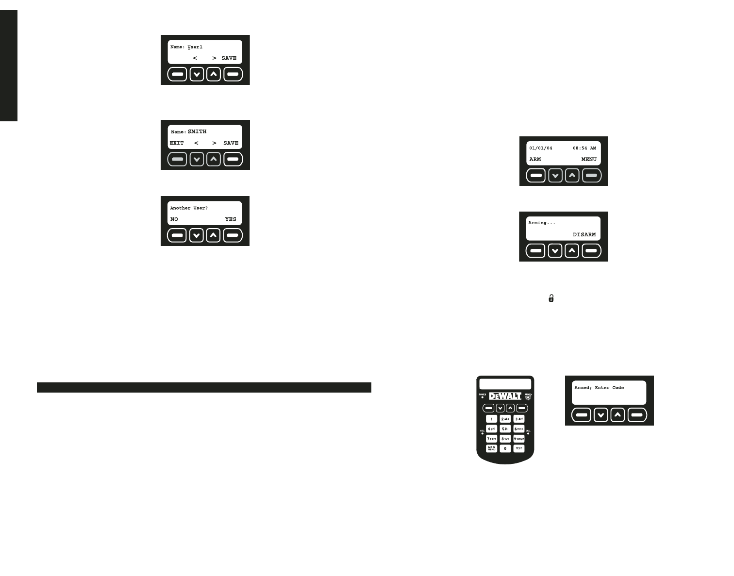
1. When the sensors have been installed in the desired location, select YES.
2. A walk test will verify that each sensor can communicate with the Base Unit. Be sure all
sensors have been installed in the desired location. Begin the walk test by selecting
YES.
3. During the test function, the system will cycle through the list of registered devices.
Each device is displayed for one second.
4. Walk through the site and trigger each sensor using the list below. As that sensor is
tripped, the entry should disappear.
Indoor Motion: Wait 90 seconds since last motion was detected then walk
through the areas where protection is expected. When motion is detected,
it will signal the Base Unit and be removed from the test list. Determine the
limits of the coverage by repeating this test until the motion is not detected.
Door/Window: Open and close the door or window to test.
Cable Lock: Open and close the lock to test.
Container Sensor: Wait 60 seconds since the last container vibration, then
create vibration on the container to test. Adjust sensitivity as necessary.
Outdoor Motion: Wait 90 seconds since last motion was detected then walk
through the areas where protection is expected. When motion is detected, it
will signal the Base Unit and be removed from the test list. Determine the lim-
its of the coverage by repeating this test until the motion is not detected.
Key Chain Remote: Press and release the lock ( ) button.
NOTE: After testing each sensor, if a sensor is still listed on the screen, see the
Troubleshooting Guide for more detailed information.
5. When the test is complete, select NEXT.
NOTE: See Test under Features and Options for more detailed information.
STEP SIX: ADD USERS
Up to 6 users (including the master user) can access the system to arm and disarm.
Additional users can be programmed at any time after the initial setup. Refer to User Code
Maintenance.
NOTE: The master user is the only user that can access the programming functions. Any
users other than the master user will only have access to arming and disarming the system.
After the devices have been registered, the Base Unit will display the Add User screen.
1. To add new users, select OK.
2. Starting with User 1, enter a four digit access code. To move back a character, use the
down arrow. To move forward a character, use the up arrow.
3. After entering the user code, select SAVE.
4. Next, enter a name for the user. Using the keypad, type the text (up to 8 characters).
The character that is being changed will be underlined. To move back a character, use
the down arrow.
English
7
To move forward a character, use the up arrow. To select letters, reference the
Alpha/Numeric Chart in the Appendix.
IMPORTANT: Write the name and corresponding user number on the Sensor
Location List. Keep this sheet for reference.
5. After entering the user name, select SAVE.
6. Select YES to add a user. The user number of the next available user will be displayed.
Continue to add users or select NO to complete the initial setup.
STEP SEVEN: MONITORING SERVICE
Setting up a monitoring service will provide an option of being contacted directly or having
the authorities notified in the event of an alarm.
After registering the devices, the screen will provide information to help set up the
monitoring service. Select OK to access the account number and the MIN required for
monitoring. If choosing to have the police notified, check with local authorities to be
sure that a monitoring service can be used. Registration may be necessary and fees
may be involved. Fees are the responsibility of the owner of the system. Contact
DEWALT customer service to set up the monitoring service.
The initial setup in now complete.
Any future changes must be made through the main menu.
See Features & Options for detailed instructions.
Arming the System
Activating the alarm to protect assets and notify if an intrusion has occurred.
• Delays
• Using the Keypad
• Using the Key Chain Remote
• Arming Automatically
IMPORTANT: After arming the system, exit before the end of the delay period or an alarm
will sound!
DELAYS
All wireless sensors and the Base Unit motion sensor are programmed with built-in
delays. This will give the user 60 seconds to exit after arming and 30 seconds to enter
before disarming without causing an alarm. Each sensor, aside from the Base Unit
motion sensor, can be changed to
Instant
so that when the system is armed, an instan-
taneous alarm occurs when the sensor is tripped.
BASIC OPERATIONS
IMPORTANT: The vibration sensor in the Base Unit and the tamper in every sensor are
automatically set to instant. This setting cannot be changed. The purpose of this setting is
to send a notification if an intruder attempts to disable or destroy the device.
See Set Delay/Instant under Features and Options for more information.
NOTE: To avoid a false alarm, sensors that are likely to be tripped as the user enters and
exits the site to arm/disarm the unit should remain set on delay mode.
USING THE KEYPAD
IMPORTANT: Arming the system introduces the risk of setting a FALSE ALARM. If unable
to disarm before the monitoring system is notified, call DEWALT customer service to report
a false alarm. If the authorities have been dispatched, a fee may be associated with the
false alarm. This fee is the responsibility of the owner of the system.
1. To arm the system, select ARM.
2. Using the keypad, enter either the master code or a valid user code.
3. For 60 seconds, the Arming screen will display indicating that the system is arming:
During arming, the Base Unit will beep for 10 seconds followed by 40 seconds of
silence. The Base Unit will beep faster during the last 10 seconds of arming.
To disarm for any reason before arming is complete, such as the need to re-enter
the premises, press the unlock button on the right of the Key Chain Remote or
select DISARM and enter either the master code or a user code.
NOTE: If Arming with Faults is displayed with continuous warning chimes, there is a
serious issue that could leave the site unsecured. You may arm over a fault (force arm);
however, it is highly recommended that the issue be corrected prior to arming. For fur-
ther information on fault codes, see Faults.
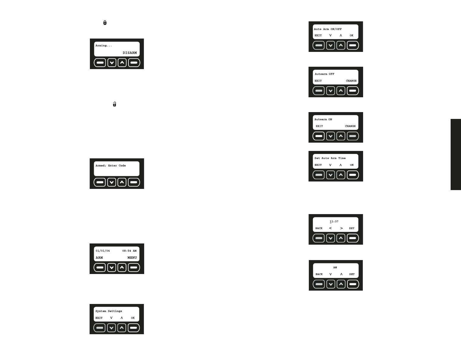
4. There are two indications that the system is armed. First, the ARMED light on the upper
right of the keypad will be on. Second, the Armed screen will be displayed.
USING THE KEY CHAIN REMOTE
The Key Chain Remote can be used for one-touch arming from up to 2000' away from the
Base Unit.
IMPORTANT: Arming the system introduces the risk of setting a FALSE ALARM. When a
device is tripped (i.e., a door is opened), immediately disarm the system. If unable to dis-
arm before the monitoring system is notified, call DEWALT customer service to report a
false alarm. If the authorities have been dispatched, a fee may be associated with the false
alarm. This fee is the responsibility of the owner of the system.
Basic Operations
8
CAUTION: LOUD NOISE. Using the Key Chain Remote to arm the system will cause a
brief loud noise that may startle any persons near the Base Unit.
1. To arm the system, press the lock button on the left side of the Key Chain Remote.
2. For 60 seconds, the screen will display the following message indicating that the
system is arming:
During arming, the Base Unit will first make a quick loud siren noise to indicate that the
signal from the Key Chain Remote was received and the system is arming. The Base
Unit will chime for 60 seconds. Finally, the Base Unit will make two quick loud siren
noises to indicate that the system is armed.
To disarm for any reason before arming is complete, such as the need to re-enter
the premises, press the unlock button on the right side of the Key Chain
Remote or select DISARM and enter either the master code or a user code.
NOTE: If Arming with Faults is displayed and a warning chime is heard, there is a
serious issue that could leave the site unsecured. You may arm over a fault (force arm);
however, it is highly recommended that the issue be corrected prior to arming. For fur-
ther information on fault codes, see Faults.
3. There are three indications that the system is armed. First, there will be a quick loud
siren noise. Second, the ARMED light on the unit will be on. Third, the Armed; Enter
Code screen will be displayed.
ARMING AUTOMATICALLY
This feature can be useful to ensure the system can be properly armed if arming cannot
be initiated by the master user or other users of the system. Once a time is set, the
system will activate at the same time each day.
CAUTION: LOUD NOISE. Enabling the auto arm feature will cause a brief loud noise while
arming that may startle any persons near the Base Unit.
To enable the automatic arming feature, be sure that the system is disarmed.
1. Start at the main screen.
2. Select MENU or press MAIN MENU on the keypad.
3. Using the keypad, enter the master code.
4. Use the up and down arrows to scroll through the menu until the System Settings
screen is displayed. Select OK.
5. Use the up and down arrows to scroll through the menu until the Auto Arm ON/OFF
screen is displayed. Select OK.
6. When the following screen appears, select CHANGE. The CHANGE button toggles
between on and off.
7. When the automatic arming is enabled, the Autoarm ON screen will appear. Select
EXIT.
8. To set the time, select OK.
9. Using the numbers on the keypad, choose a time for the system to be automatically
armed, changing hours first, then minutes.
The character that is being changed will be underlined. To move back a character, use
the down arrow. To move forward a character, use the up arrow.
10. Select SET.
11. Choose AM or PM. The up and down arrows are used to toggle between AM and PM.
12. Select SET.
IMPORTANT: If for any reason the system is disarmed after the auto arm time and the
site still requires protection, the system will need to be re-armed using the Key Chain
Remote or keypad. The following day, the auto arm will continue to auto arm at the pre-
set time.
Disarming the System
Deactivating the system to be able to make changes, open doors, etc., without setting an
alarm response.
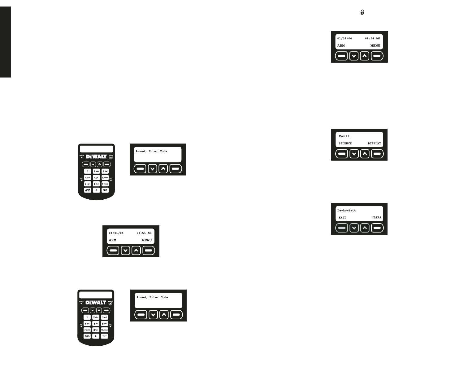
English
9
• Entry Delays
• Using the Keypad
• Using the Key Chain Remote
ENTRY DELAYS
Each sensor aside from the Base Unit motion sensor can be reset for
Instant
which elim-
inates the entry delay. By changing a device to instant, when the system is armed an alarm
will take place as soon as the device is tripped.
IMPORTANT: The vibration sensor in the Base Unit and the tamper in every sensor are
automatically set to instant. This setting cannot be changed. The purpose of this setting is
to send a notification if an intruder attempts to disable or destroy the device.
IMPORTANT: To avoid a false alarm, sensors that are likely to be tripped as the user enters
and exits the site to arm/disarm the unit should remain set on delay mode.
For more information, see Set Delay/Instant under Features and Options.
USING THE KEYPAD
IMPORTANT: Avoid causing vibration in the Base Unit when typing the master
code. The vibration sensor will be on as soon as the internal motion detector recognizes
motion. When a vibration occurs, the unit will send an alarm. This is to provide protection
of damage or destruction of the Base Unit. If the vibration sensor is accidentally tripped,
the system will immediately contact the monitoring system.
When the system is armed, the Armed screen will be displayed:
1. To disarm the system, use the keypad to enter either the master code or a valid user
code.
2. The main screen will be displayed. The ARMED light on the unit will be off.
USING THE KEY CHAIN REMOTE
Use the Key Chain Remote for one-touch disarming from up to 2000' away from the
Base Unit.
When the system is armed, the Armed screen will be displayed:
1. To disarm the system, press the unlock button on the right side of the Key Chain
Remote.
2. The main screen will be displayed. The ARMED light on the unit will be off.
Faults
Faults indicate when there has been a serious issue that needs to be addressed. This
could be a number of things including an unsecured device, low battery, tamper and weak
signal.
• How to View Faults
• Clearing a Fault
• Description of Fault Codes
HOW TO VIEW FAULTS
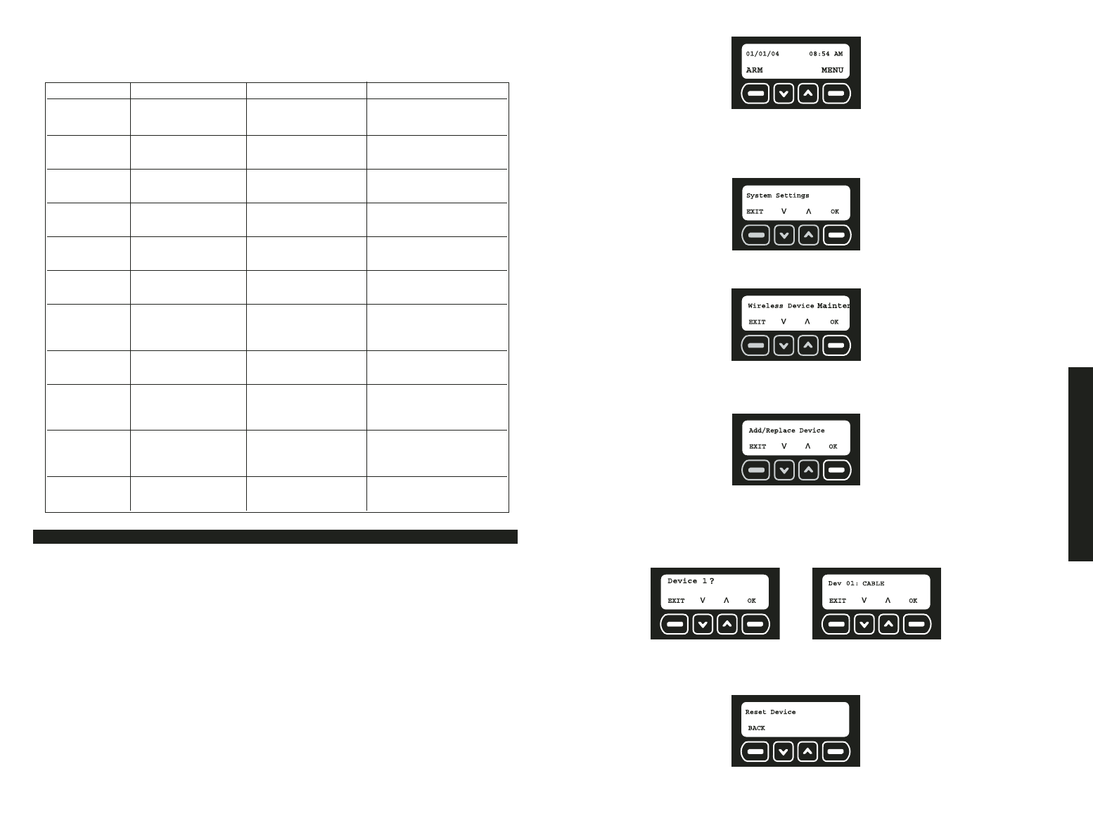
If a fault is present, the system will chime and display the Fault screen.
1. To silence the chime, select SILENCE. This will simply allow the system to be armed
over a fault and/or silence the chime. It is recommended to correct the fault as soon as
possible. To display the fault and resolve immediately, select DISPLAY.
2. The fault code will be displayed. Use the up and down arrows to scroll through the
faults. Resolve the issue with the action listed in Description of Fault Codes chart and
the Fault screen will disappear. To remove a tamper fault, select CLEAR.
IMPORTANT: See the Description of Fault Codes for more details regarding a fault and
resolution actions. All faults, except a tamper, will automatically be cleared when the issue
has been resolved. An event will be recorded in the event log indicating the date and time
that the event occurred and was resolved.
NOTE: A tamper fault will not be automatically cleared. After the device has been
inspected, checked for damage, and the cover closed, the fault will need to be cleared.
See Clearing a Fault. This process was designed to create awareness of the tamper
with the master user and require verification that the problem has been resolved.
CLEARING A FAULT
To clear any fault other than a tamper fault, correct the condition at the sensor. For
example: replace the battery, relocate to an area with a better signal, etc.
To Clear a Tamper Fault:
IMPORTANT: Before clearing a tamper fault, be sure that the issue has been resolved.
Only the master user can clear tamper faults.
1. When the Fault Code screen is displayed; select CLEAR.
2. Use the keypad to enter the master code.
3. Select OK.
Features & Options
10
DESCRIPTION OF FAULT CODES
NOTE: See the Troubleshooting Guide for more detailed information.
System Settings
The systems settings menu allows for changes in user codes, wireless devices, automatic
arming, delays and account information.
• Wireless Device Maintenance • Clear Settings
• Change Master Code • Auto Arm ON/OFF
• User Code Maintenance • Auto Arm Time Set
• Set Console Devices • Review Account
• Set Delay/Instant • Choose Language
WIRELESS DEVICE MAINTENANCE
After the initial setup, a device such as a sensor or Key Chain Remote can be added,
edited or removed.
• Adding or Replacing a Device
• Editing a Device
• Removing a Device
FEATURES & OPTIONS
Fault Code Fault Display Description Action
Power Primary Power No power to Check power supply
Lost Base Base Unit
DevPower Primary Power Lost No battery power Change battery, reset
Device # in device
BaseLowBatt Base Base Unit Plug in power supply
Low Battery battery low to recharge battery
DevLowBatt Low Battery Device battery Change battery, reset
Device # low
WeakSig Weak Signal Transmission signal Check for interference;
Device # from device is weak move device
Unsecured Unsecured Device has Check for intrusion;
Device # been tripped re-secure device
NoCheckIn No Check In Device check-in Check for interference;
Device # messages have not move device
been received
Tamper Tamper Device has been Close device or
opened or damaged replace if damaged
BaseBadBatt Bad Battery Base Unit battery has Needs to be repaired
Base dropped below the at DEWALT authorized
voltage limit service center
CellRadio Cell Radio Cellular radio Move Base Unit to
Fault signal is lost a location where
CELL light is solid
Receiver Receiver Fault 2-way transmission Call customer service
Device # of device is lost to test system for issues
DESCRIPTION OF FAULT CODES
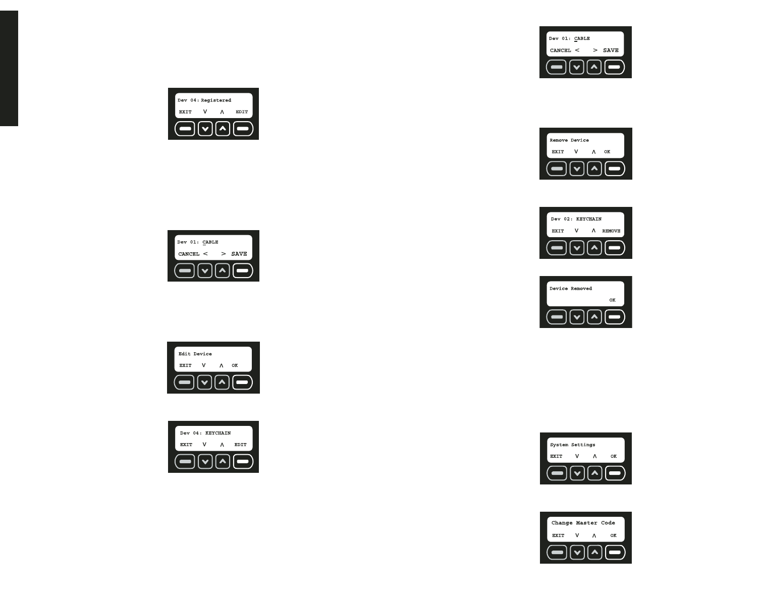
1. Start at the main screen.
2. Select MENU or press MAIN MENU on the keypad.
3. Using the keypad, enter the master code.
4. Use the up and down arrows to scroll through the menu until the System Settings
screen is displayed. Select OK.
5. Use the up and down arrows to scroll through the menu until the Wireless Device
Maintenance screen is displayed. Select OK.
To Add a Device:
1. Use the up and down arrows to scroll through the menu until the Add/Replace Device
screen is displayed. Select OK.
2. The next available device number will be displayed. If there are no slots available, the
screen will display ALL DEVICES IN USE.
To replace a device, use the up and down arrows to select the device to be replaced.
If a previously programmed device is selected, the old device will be overwritten when
the reset button on the new device is pressed.
3. When the device number is shown, select OK. The device will not register until after
the OK button is pressed and device has been reset.
4. Reset the device.
English
11
NOTE: Each device has a reset button that must be pressed and released. To
locate the reset button, refer to the instructions for each particular device. Be sure
that batteries are properly installed in each device. Press the reset button now.
5. The screen will indicate that the device has been registered with the following screen.
Only 48 sensors and 6 Key Chain Remotes can be added. If there are no slots avail-
able, the screen will display ALL DEVICES IN USE. To edit the description of the
device, select EDIT. To add another device, select EXIT.
6. To edit the description, use the keypad to type a description (up to 8 characters). The
character that is being changed will be underlined. To move back a character, use the
down arrow. To move forward a character, use the up arrow.
IMPORTANT: Write the device description and corresponding device number on the
Sensor Location List. Keep this sheet for reference. This information will be needed
during the monitoring service enrollment process. The location and descriptions for
each device are critical for the monitoring of the system.
7. Select SAVE.
IMPORTANT: As device changes are made, be sure to contact DEWALT customer
service to make adjustments.
To Edit a Device:
1. Use the up and down arrows to scroll through the menu until the Edit Device screen is
displayed. Select OK.
2. Use the up and down arrows to scroll through the list until the device to be edited is
reached. Select EDIT.
3. To edit the description, use the keypad to type a description (up to 8 characters). The
character that is being changed will be underlined. To move back a character, use the
down arrow. To move forward a character, use the up arrow.
IMPORTANT: Write the device description and corresponding device number on the
Sensor Location List. Keep this sheet for reference. This information will be needed
during the monitoring service enrollment process. The location and descriptions for
each device is critical for the monitoring of the system.
4. Select SAVE.
5. Select EXIT.
To Remove a Device:
1. Use the up and down arrows to scroll through the menu until the Remove Device
screen is displayed. Select OK.
2. Use the up and down arrows to scroll through the list until the device to be removed is
reached. Select REMOVE.
3. The system will indicate that the device has been removed. Select OK.
CHANGE MASTER CODE
The master code enables ONLY the master user to make programming changes to the
system as well as arm and disarm. The master code can be changed at any time while the
system is disarmed.
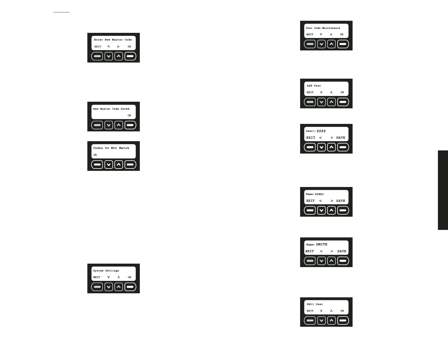
1. Start at the main screen.
2. Select MENU or press MAIN MENU on the keypad.
3. Using the keypad, enter the master code.
4. Use the up and down arrows to scroll through the menu until the System Settings
screen is displayed. Select OK.
5. Use the up and down arrows to scroll through the menu until the Change Master Code
screen is displayed. Select OK.
Features & Options
12
6. Re-enter the
current
master code. This allows verification that the master user is
making the change.
7. If a valid master code is entered, the system will ask for a new master code. Using the
numbers on the keypad, enter a new four digit master code. Then, select OK.
8. Re-enter the new master code to confirm. Again, using the numbers on the keypad,
enter the new four digit master code. The character that is being changed will be under-
lined. To move back a character, use the down arrow. To move forward a character,
use the up arrow. Then, select OK.
9. If the codes match, the system will confirm that the master code has been changed.
Select OK.
NOTE: If the codes do not match, the Codes Do Not Match screen is displayed:
If Master Codes Do Not Match
1. Select OK.
2. The Change Master Code screen is displayed (Step 5, Change Master Code). The
original master code is the default code until it is changed and verified.
USER CODE MAINTENANCE
After the initial setup, a user code and name can be added, edited or removed.
• Adding a User
• Editing a User
• Removing a User
1. Start at the main screen.
2. Select MENU or press MAIN MENU on the keypad.
3. Using the keypad, enter the master code.
4. Use the up and down arrows to scroll through the menu until the System Settings
screen is displayed. Select OK.
5. Use the up and down arrows to scroll through the menu until the User Code
Maintenance screen is displayed. Select OK.
To Add a User
NOTE: Up to 6 users including the master user can be programmed.
1. Use the up and down arrows to scroll through the menu until the Add User screen is
displayed. Select OK.
2. Starting with the next available user, enter a four digit access code. To move back a
character, use the down arrow. To move forward a character, use the up arrow.
3. After entering the user code, select SAVE.
4. Next, add the name for the user. Use the keypad to type a name (up to 8 characters).
The character that is being changed will be underlined. To move back a character, use
the down arrow. To move forward a character, use the up arrow. To select letters,
reference the Alpha/Numeric Chart in the Appendix.
IMPORTANT: Write the name and corresponding user number on the Sensor
Location List. Keep this sheet for reference.
5. Select SAVE.
6. Continue to add users or choose EXIT.
To Edit a User
1. Use the up and down arrows to scroll through the menu until the Edit User screen is
displayed. Select OK.
English
13
2. Use the up and down arrows to scroll through the users to select the user to be edited.
Select EDIT.
3. To change the user code, enter a new four digit access code. To move back a
character, use the down arrow. To move forward a character, use the up arrow.
Select SAVE.
4. Next, edit the name for the user. Use the keypad to type a name (up to 8 characters).
The character that is being changed will be underlined. To move back a character, use
the down arrow. To move forward a character, use the up arrow. To select letters,
reference the Alpha/Numeric Chart in the Appendix.
NOTE: Write the name and corresponding user number on the Sensor Location List.
Keep this sheet for reference.
5. Select SAVE.
6. Continue to edit users or choose EXIT.
To Remove a User
1. Use the up and down arrows to scroll through the menu until the Remove User screen
is displayed. Select OK.
2. Use the up and down arrows to scroll through the users to select the user to be
removed. Select REMOVE.
3. The system will confirm that the user has been removed. Select OK.
4. Continue to delete users or choose EXIT.
SET CONSOLE DEVICES
The Base Unit contains a siren and a strobe light. They provide notification of an alarm
occurrence. Although it is not recommended, the siren and strobe can be turned off and
will not operate if an alarm occurs.
1. Start at the main screen.
2. Select MENU or press MAIN MENU on the keypad.
3. Using the keypad, enter the master code.
4. Use the up and down arrows to scroll through the menu until the System Settings
screen is displayed. Select OK.
5. Use the up and down arrows to scroll through the menu until the Set Console Devices
On/Off screen is displayed. Select OK.
6. Using the up and down arrows, scroll to choose between strobe and siren. The screen
will indicate whether the strobe/siren is currently set on or off. To change the status,
select CHANGE.
7. Once all settings are to the user’s preference, select BACK.
SET DELAY/INSTANT
Each sensor aside from the Base Unit motion sensor can be reset for
Instant
which elim-
inates the entry delay. By changing a device to
Instant
, when the system is armed, an
alarm will take place as soon as the device is tripped.
NOTE: The vibration sensor in the Base Unit and the tamper in every sensor are automat-
ically set to Instant. This setting cannot be changed. The purpose of this setting is to send
a notification if an intruder attempts to disable or destroy the device.
NOTE: To avoid a false alarm, sensors that are likely to be tripped as the user enters and
exits the site to arm/disarm the unit should remain set on delay mode.
1. Start at the main screen.
2. Select MENU or press MAIN MENU on the keypad.
3. Using the keypad, enter the master code.