JADAK a business unit of Novanta MERCURY6E-M RFID Module User Manual M6e Micro HardwareGuide
Trimble Navigation Limited RFID Module M6e Micro HardwareGuide
UserManual.wiki
>
JADAK a business unit of Novanta
>
MERCURY6E-M User Manual
>
Manual
Contents
1.
Manual
2.
User manual revised
3.
User Manual 1
4.
User Manual 2
5.
User Manual 3
6.
User Manual
7.
Users Manual
8.
Part 1
9.
Part 2
10.
Part 3
11.
Part4
12.
Compliance Statements
Manual
Navigation menu
Upload a User Manual
Namespaces
Wiki Guide
HTML
PDF
Info
Views
User Manual
Discussion / Help
Navigation


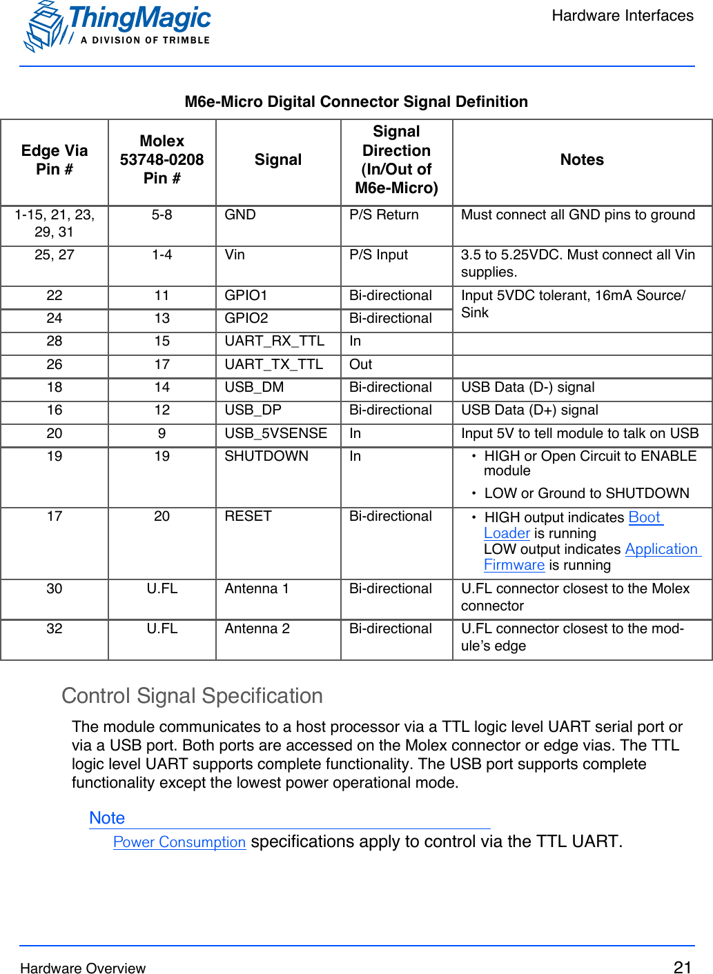


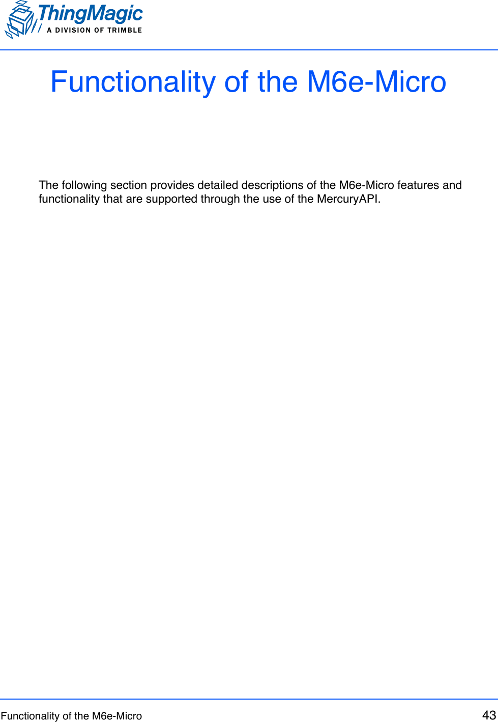
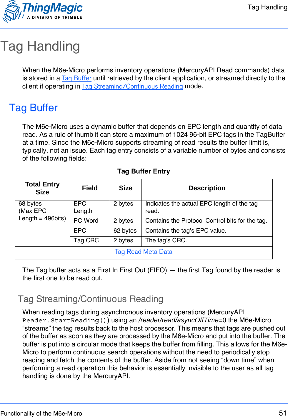
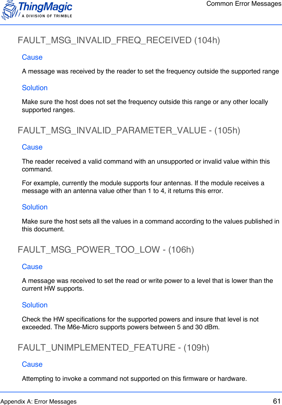
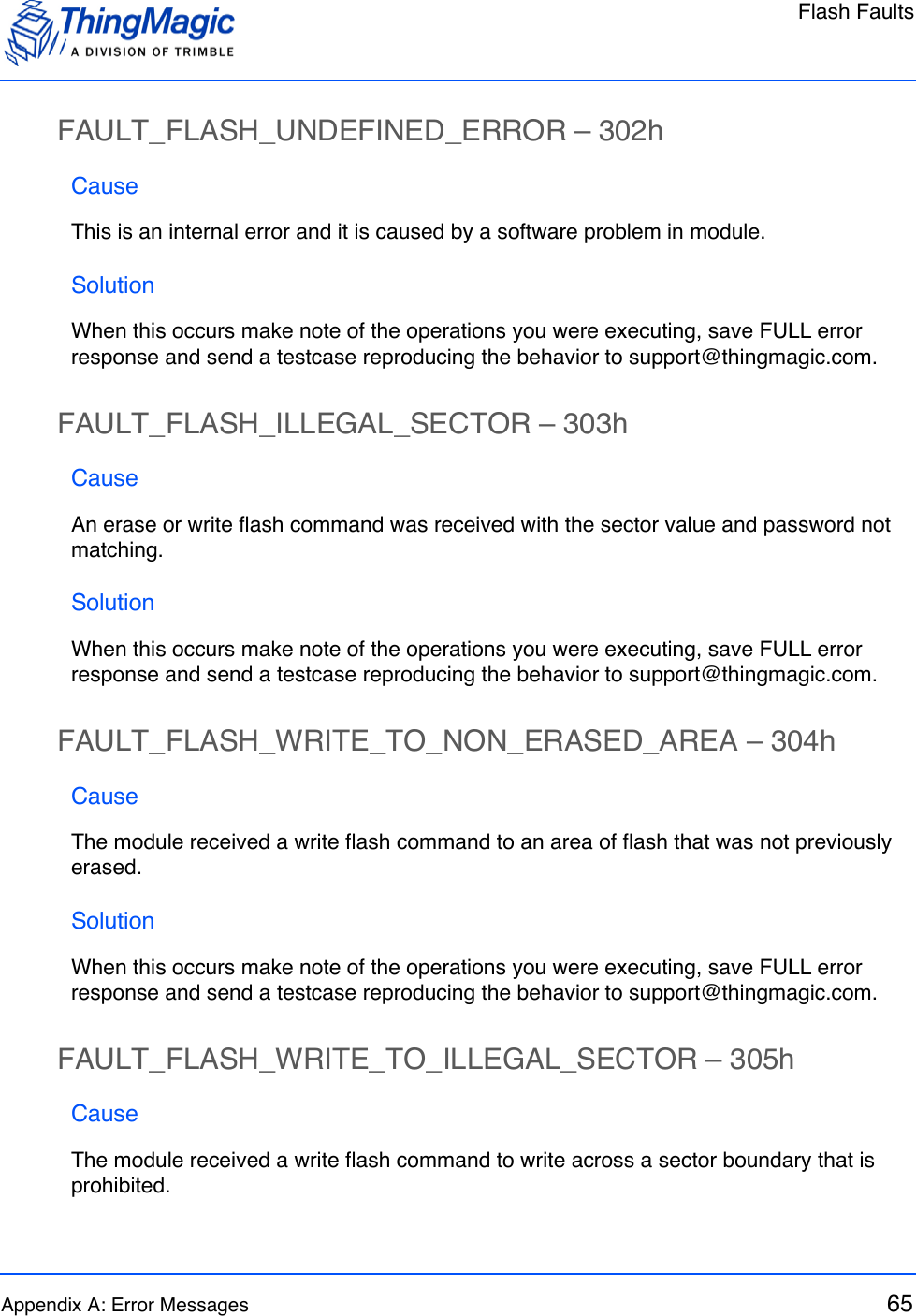
![Tag Read Meta DataA DIVISION OF TRIMBLEFunctionality of the M6e-Micro 53Tag Read Meta DataIn addition to the tag EPC ID resulting from M6e-Micro inventory operation each TagReadData (see MercuryAPI for code details) contains meta data about how, where and when the tag was read. The specific meta data available for each tag read is as follows:Tag Read Meta DataMeta Data Field DescriptionAntenna ID The antenna on with the tag was read. If the same tag is read on more than one antenna there will be a tag buffer entry for each antenna on which the tag was read. When Using a Multi-plexer, if appropriately configured, the Antenna ID entry will contain the logical antenna port of the tag read.Read Count The number of times the tag was read on [Antenna ID]. Timestamp The time the tag was read, relative to the time the command to read was issued, in milliseconds. If the Tag Read Meta Data is not retrieved from the Tag Buffer between read commands there will be no way to distinguish order of tags read with dif-ferent read command invocations. Tag Data When reading an embedded TagOp is specified for a Read-Plan the TagReadData will contain the first 32 words of data returned for each tag. Note: Tags with the same TagID but different Tag Data can be considered unique and each get a Tag Buffer entry if set in the reader configuration parameter /reader/tagReadData/uniqueByData. By default it is not.Frequency The frequency on which the tag was readTag Phase Average phase of tag response in degrees (0°-180°)LQI/RSSI The receive signal strength of the tag response in dBm.GPIO Status The signal status (High or Low) of all GPIO pins when tag was read.](https://usermanual.wiki/JADAK-a-business-unit-of-Novanta/MERCURY6E-M.Manual/User-Guide-1849459-Page-53.png)

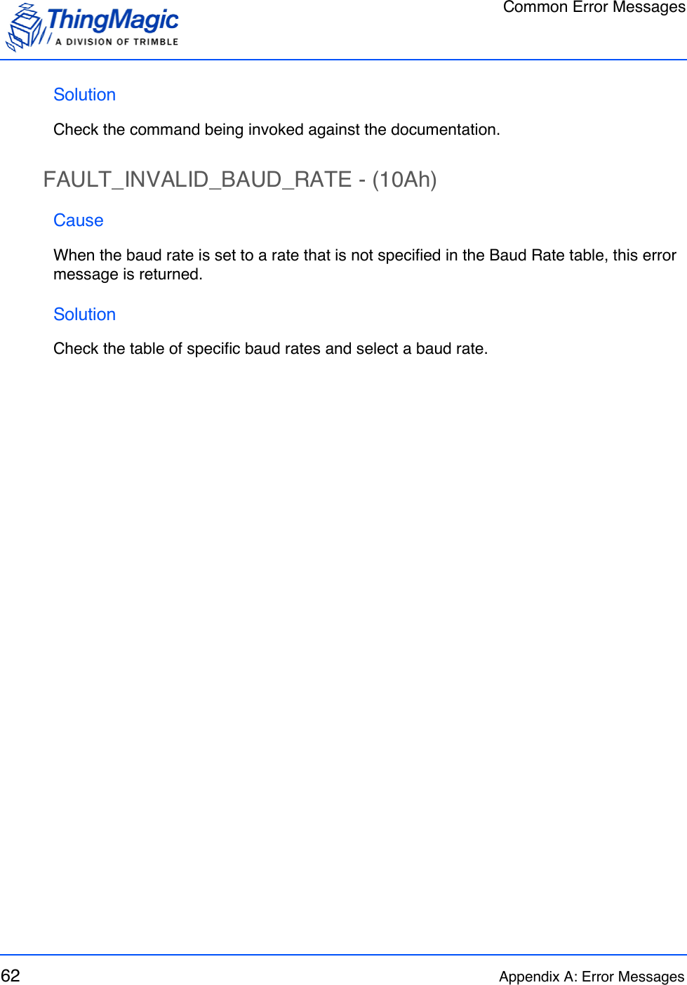
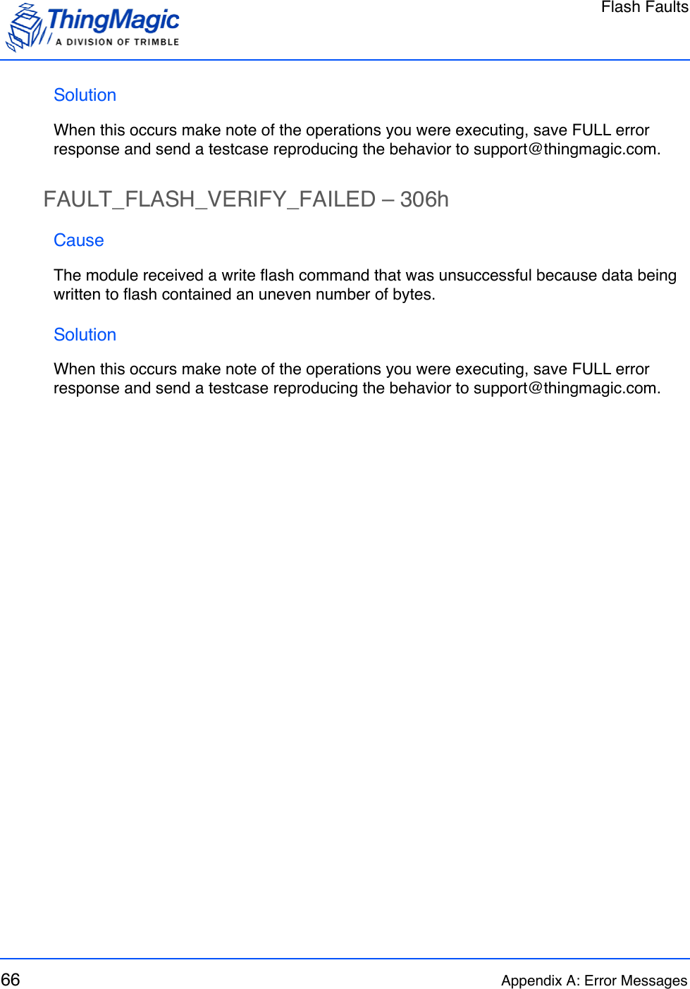
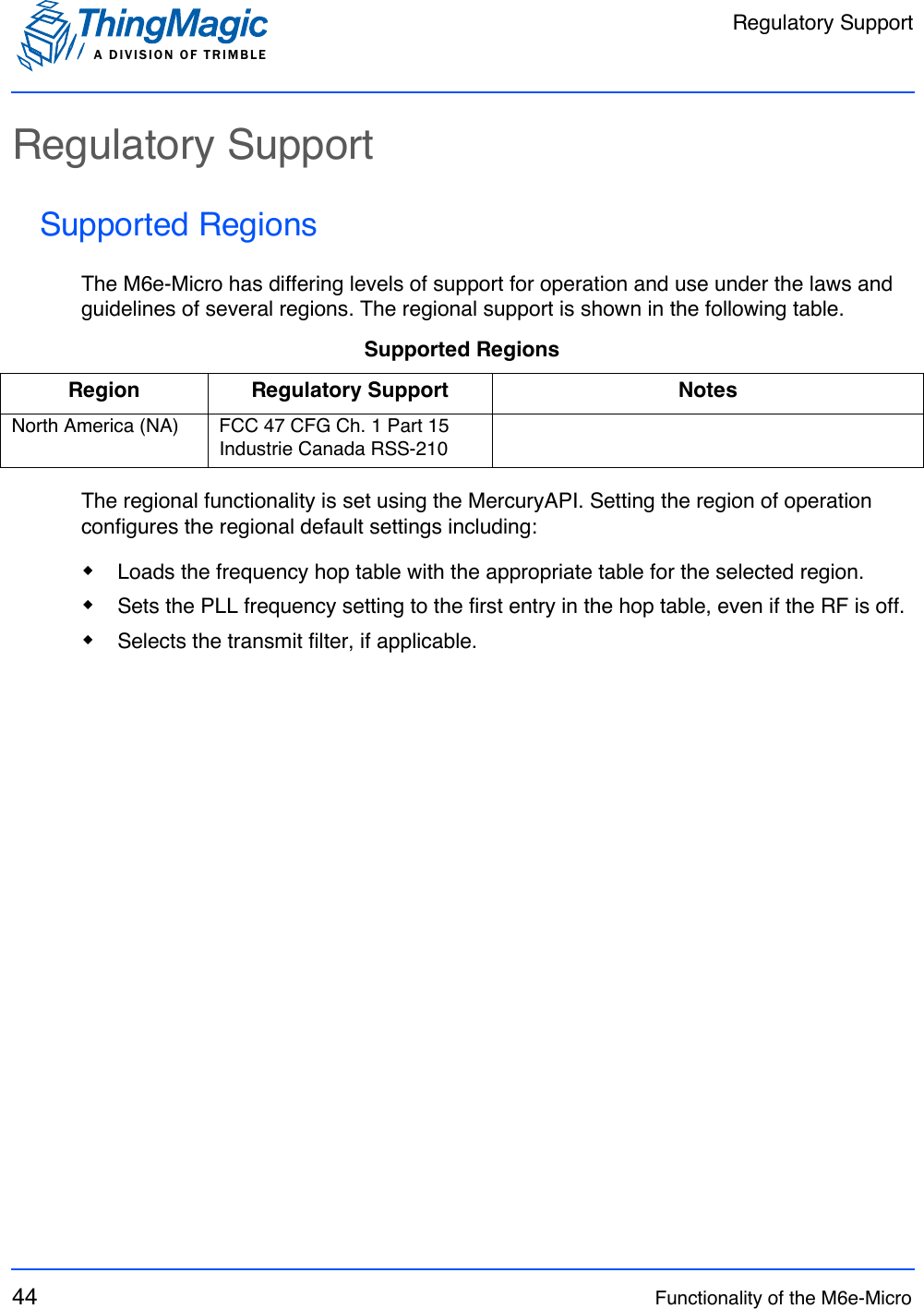
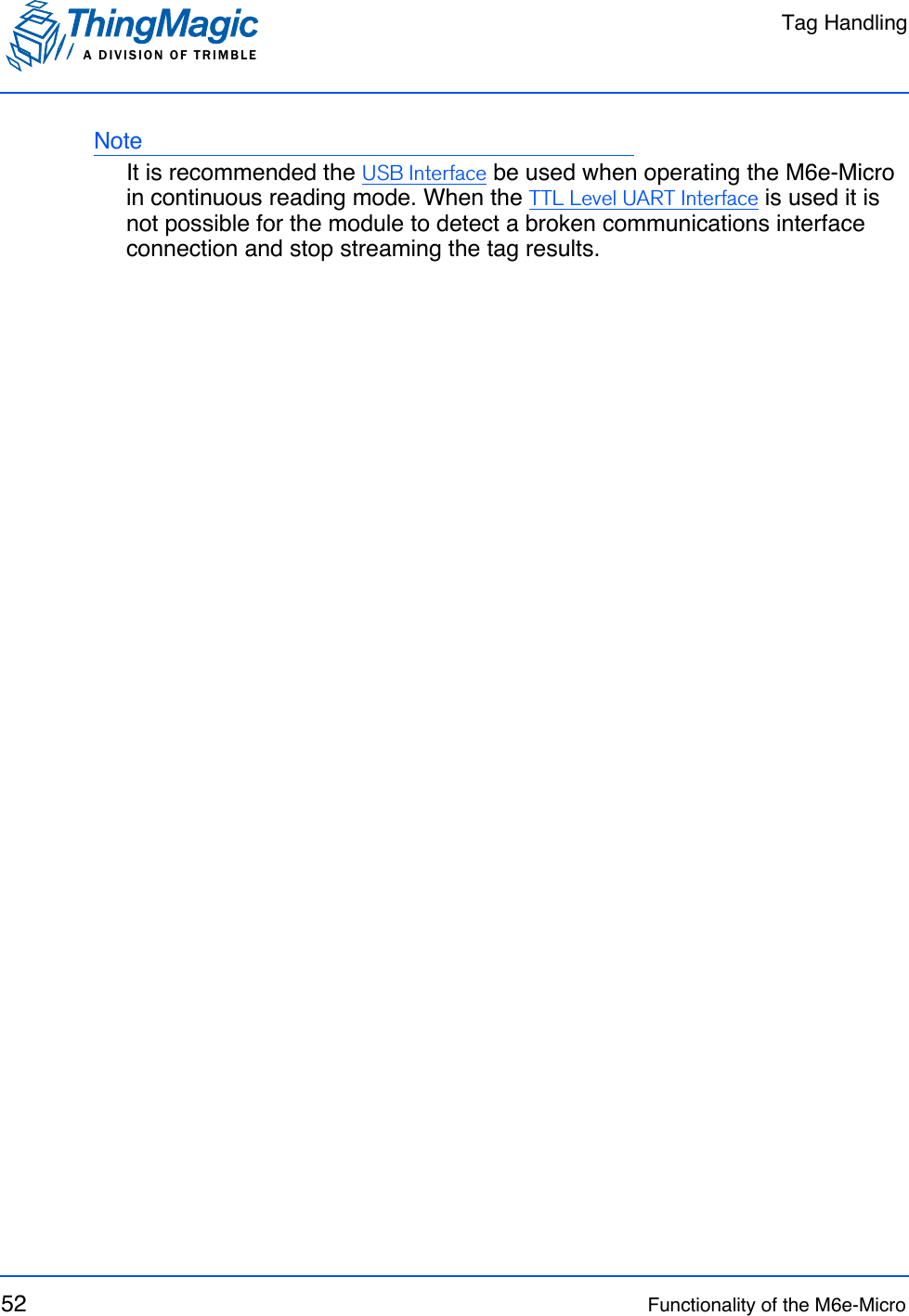
![Devkit Hardware84 Appendix B: Getting Started - Devkitc. Select View | Devices by Type | Ports (COM & LPT) The device appears as Mercury6eUltra (COM#).Devkit JumpersJ8Jumpers to connect M6e-Micro I/O lines to devkit. J9Header for alternate power supply. Make sure DC plug (J1) is not connected if using J9.J10, J11, J13, J15Jump pins OUT to GPIO# to connect M6e-Micro GPIO lines to output LEDs. Jumpe pins IN to GPIO# to connect M6e-Micro GPIO to corresponding input switches SW[3-6]GPIO#. Make sure GPIO lines are correspondingly configured as input or outputs (see Configuring GPIO Settings).J14Can be used to connect GPIO lines to external circuits. If used jumpers should be removed from J10, J11, J13, J15.J16Jump pins 1 and 2 or 2 and 3 to reset devkit power supply. Same as using switch SW1 except allows for control by external circuit.J17Jump pins 1 and 2 to use the 5V INPUT and GND inputs to provide power. Jump pins 2 and 3 to use the DevKitʼs DC power jack and power brick power.J19Jump SHUTDOWN to GND to enable module. While grounded SHUTDOWN pushbutton (SW2) will break circuit and shutdown the M6e-Micro (see M6e-Micro Digital Connector Signal Definition). AUTO_BOOT controls Reset Line.](https://usermanual.wiki/JADAK-a-business-unit-of-Novanta/MERCURY6E-M.Manual/User-Guide-1849459-Page-84.png)